msd50 mechanical stern drive documents/drive_units... · instruction manual 21119664f 7 3...
TRANSCRIPT
MANUAL
SIMRAD MSD50 Mechanical Stern Drive
21119664F English


Instruction Manual
21119664F 1
Instruction Manual This manual is intended as a reference guide for correctly installing and set-up of the Simrad MSD50 Mechanical Stern Drive. Please take time to read the manual to get a thorough understanding of the stern drive and its relationship to a complete autopilot system. Other documentation materials that are provided with your system include a warranty card. This must be filled out by the authorized dealer that performed the installation and mailed in to activate the warranty.

Simrad MSD50 Mechanical Stern Drive
2 21119664F
About this document
Rev Date Written by Checked by Approved by
16.02.05 NG ThH Rev. F Updated with identification dent on kit no. 1.
© 2005 Simrad AS. All rights reserved. No part of this work covered by the copyright hereon may be reproduced or otherwise copied without prior permission from Simrad AS. The information contained in this document is subject to change without prior notice. Simrad AS shall not be liable for errors contained herein, or for incidental or consequential damages in connection with the furnishing, performance, or use of this document.

Instruction Manual
21119664F 3
1 GENERAL INFORMATION ...............................................................................5 1.1 Introduction ....................................................................................................5
2 TECHNICAL SPECIFICATIONS.......................................................................6
3 INSTALLATION ...................................................................................................7 3.1 MSD50 mounting ...........................................................................................7
Kit no. 1 (Volvo Penta stern drive KAD42/43/44/32)...............................8 Kit no. 2 (Mercruiser stern drive, diesel engines 93 )...........................10 Kit no. 2 (Mercruiser, OMC and Yamaha stern drives) ..........................12 Kit no. 2 (Volvo Penta DP-S drives, Gas engines from autumn -97)......14 Kit no. 3 (Mercruiser stern drive 93-96 gas engine)................................16 Kit no. 3 (Mercruiser stern drive 96- gas engine .....................................18 Kit no. 4 (Volvo Penta stern drive -41 series) .........................................20
3.2 Electrical connection ....................................................................................22 3.3 Alignment .....................................................................................................22
4 SPARE PARTS.....................................................................................................23

Simrad MSD50 Mechanical Stern Drive
4 21119664F

Instruction Manual
21119664F 5
1 GENERAL INFORMATION
1.1 Introduction This manual contains installation and set-up instructions for the MSD50 Mechanical Stern Drive. On stern drive boats (inboard/outboard) with power assisted steering, the Simrad MSD50 stern drive unit will operate the servo valve to automatically steer the boat. The MSD50 is attached to the servo unit and operates the servo valve in the same way as the push-pull (“Teleflex”) cable from the helm. The MSD50 generates a feedback signal to the autopilot which is relative to the motion of the actuator rod and can only be operated from autopilots that are using the AC10, AC20, AC40 autopilot computers or J300X, J300X-40 and J3000X junction units. At turn on the zero point (mid. position) of the “rudder” feedback signal will be set by a simple operational procedure.
Note If you prefer to have an absolute rudder feedback signal, i.e. you need not set the zero point at turn on, consult your Simrad dealer to have a standard RF300 rudder feedback unit installed. The RF300 input will replace the feedback signal coming from the MSD50.
There is no change in the installation set-up of the autopilot with an MSD50 installed as compared to the standard set-up described in the autopilot manual. The only difference is the setting of the “rudder” zero point as described in the AP16, AP25, AP26/AP27, AP11, AP20 and AP21/AP22 manuals respectively.
Installation instructions for MSD50 on different engines and stern drives are found in this manual as well as instructions for change of software programme in the autopilot junction unit when necessary.
Note MSD50 can not be used on installations where the servo valve is operated by a hand hydraulic steering system (Then use RPU80 Pump Unit + RF300 Feedback Unit).

Simrad MSD50 Mechanical Stern Drive
6 21119664F
2 TECHNICAL SPECIFICATIONS Dimensions: ............................................................. See Figure 1. Weight: ............................................ 1,8 kg (including 7 m cable) Protection:.............................................................................. IP44 Motor supply from autopilot computer/junction unit: 5 - 14V DC Thrust:..................................................................................500 N Stroke length: .................................................................. 190 mm Actuator speed at nominal voltage: ............................ 15 mm/sec. Ambient temperature:
Storage –30 - +80°C Operation 0 - +55°C
Maximum power consumption: .............................................40W
Figure 1 MSD50 – Dimensions

Instruction Manual
21119664F 7
3 INSTALLATION
3.1 MSD50 mounting The MSD50 can be installed on stern drives with power assisted steering of the type Volvo, Mercruiser, Yamaha and OMC. Four different types of mounting kits are available.
Note Due to the different stern drives and different boat models, it is important to verify that the MSD50 will fit the actual stern drive in the particular boat.
Particular attention has to be made to the positioning of the washers and the plastic spacer to get the MSD50 exactly parallel to the linear movement of the servo. The following table gives you the relation between mounting kits and different types and models of stern drives.
Kit no. 1 P/N 21119516
Kit no. 2 P/N 21119656
Kit no. 3 P/N 21119672
Kit no. 4 P/N 21119755
Volvo Penta KAD42/43/44/32 series and most models after 1993
X
Volvo Penta -41 series. Old type servo up to 1993
X
Volvo Penta Gas engines/DP-S drives from 1997
X
“All” Mercruiser models up to 1993.
X
Mercruiser diesel from 1993 and later
X
Mercruiser gas/petrol from 1993 and newer
X
OMC and Yamaha X
Make sure you have got the correct type of mounting kit supplied with the MSD50.
Simrad MSD50 Mechanical Stern Drive
8 21119664F
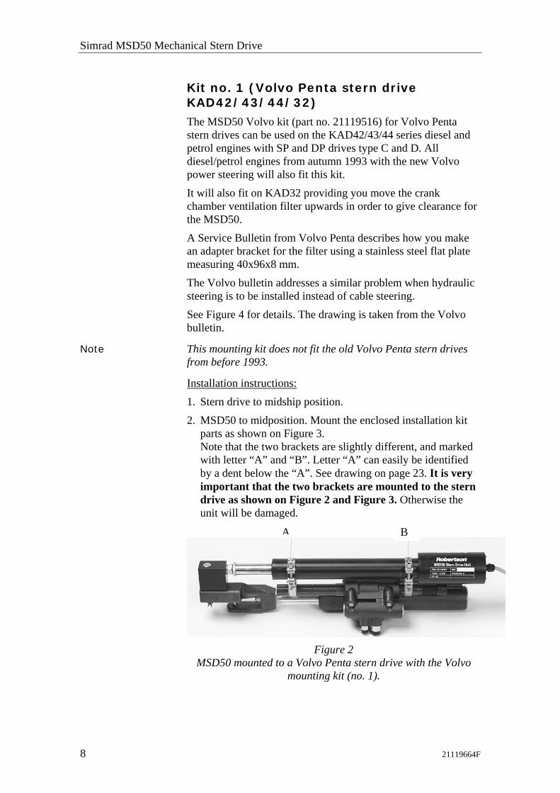
Kit no. 1 (Volvo Penta stern drive KAD42/43/44/32)
The MSD50 Volvo kit (part no. 21119516) for Volvo Penta stern drives can be used on the KAD42/43/44 series diesel and petrol engines with SP and DP drives type C and D. All diesel/petrol engines from autumn 1993 with the new Volvo power steering will also fit this kit. It will also fit on KAD32 providing you move the crank chamber ventilation filter upwards in order to give clearance for the MSD50. A Service Bulletin from Volvo Penta describes how you make an adapter bracket for the filter using a stainless steel flat plate measuring 40x96x8 mm. The Volvo bulletin addresses a similar problem when hydraulic steering is to be installed instead of cable steering. See Figure 4 for details. The drawing is taken from the Volvo bulletin.
Note This mounting kit does not fit the old Volvo Penta stern drives from before 1993.
Installation instructions: 1. Stern drive to midship position. 2. MSD50 to midposition. Mount the enclosed installation kit
parts as shown on Figure 3. Note that the two brackets are slightly different, and marked with letter “A” and “B”. Letter “A” can easily be identified by a dent below the “A”. See drawing on page 23. It is very important that the two brackets are mounted to the stern drive as shown on Figure 2 and Figure 3. Otherwise the unit will be damaged.
Figure 2
MSD50 mounted to a Volvo Penta stern drive with the Volvo mounting kit (no. 1).
A B

Instruction Manual
21119664F 9
3. Check the “rudder” movement from one side to the other. Be sure that the MSD50 is NOT acting as an end stop for the servo unit. It is also very important that the MSD50 and the mounting kit do not touch any part of the engine, steering system or other obstacles.
4. The MSD50 installation is subjected to large amounts of vibration. It is essential to ensure that all bolts are fully tightened. Retighten all bolts after the first sea trial.
Figure 3
Installation drawing for MSD50/kit no. 1 on Volvo stern drive (KAD42)

Simrad MSD50 Mechanical Stern Drive
10 21119664F
Figure 4
MSD50/KAD32 Adapter Bracket
Kit no. 2 (Mercruiser stern drive, diesel engines 93 )
Figure 5
MSD50 mounted to a Mercruiser stern drive with mounting kit no. 2.
Installation instructions:
1. Stern drive to midship position. 2. MSD50 to midposition. Mount the enclosed installation kit
parts as shown on the installation drawing. Note that the part marked “A” is placed under and facing the MSD50 rod. Also make sure that the mounting bracket plate is correctly mounted; i.e. off centre (See Figure 6) Place the plastic spacer as shown on the drawing. Otherwise the unit will be damaged.
3. Check the “rudder” movement from one side to the other. Be sure that the MSD50 is NOT acting as an endstop for the servo unit. It is also very important that the MSD50 and the mounting kit do not touch any part of the engine, steering system or other obstacles.
4. The MSD50 installation is subjected to large amounts of vibration. It is essential to ensure that all bolts are fully tightened. Retighten all bolts after the first seatrial.
Adapter bracket

Instruction Manual
21119664F 11
Figure 6
Installation drawing for MSD50/kit no. 2 Mercruiser stern drive, diesel engine 93

Simrad MSD50 Mechanical Stern Drive
12 21119664F
Kit no. 2 (Mercruiser, OMC and Yamaha stern drives)
Figure 7
Old model Mercruiser stern drive ( 93)
Installation instructions: 1. Stern drive to midship position. 2. MSD50 to midposition. Install the enclosed mounting kit
parts as shown on Figure 8. Note that the part marked “A” must be placed as shown with the “A” facing the MSD50 rod. Also make sure that the mounting bracket plate is correctly mounted off centre.
3. Place the plastic spacer as shown on the drawing. Otherwise the unit will be damaged. Note that the kit includes two washers that are not used for this installation.
4. Check the “rudder” movement from one side to the other. Be sure that the MSD50 is NOT acting as an end stop for the servo unit. It is also very important that the MSD50 and the mounting kit do not touch any part of the engine, steering system or other obstacles.
5. The MSD50 installation is subjected to large amounts of vibration. It is essential to ensure that all bolts are fully tightened. Retighten all bolts after the first sea trial.

Instruction Manual
21119664F 13
Figure 8
Installation drawing for MSD50/kit no. 2 on Yamaha, OMC and old model Mercruiser stern drives

Simrad MSD50 Mechanical Stern Drive
14 21119664F
Kit no. 2 (Volvo Penta DP-S drives, Gas engines from autumn -97)
The servo unit has Volvo part no. 872 215-9 and is used on DP-S drives on following gas engines: 4,2GL, 4,3GS, 4,3Gi, 5,0GL, 5,0Gi, 5,7GS, 5,7Gsi, 7,4Gi, 7,4Gsi, 8,2GSi
Figure 9
MSD50 mounted to a Volvo Penta DP-S stern drive with mounting kit no. 2.
Installation instructions: 1. Stern drive to midship position. 2. MSD50 to midposition. Mount the enclosed installation kit
parts as shown on the installation drawing. Place the plastic spacer and the two washers as shown on the drawing. Otherwise the unit will be damaged.
3. Check the “rudder” movement from one side to the other. Be sure that the MSD50 is NOT acting as an end stop for the servo unit. It is also very important that the MSD50 and the mounting kit do not touch any part of the engine, steering system or other obstacles.
4. The MSD50 installation is subjected to large amounts of vibration. It is essential to ensure that all bolts are fully tightened. Retighten all bolts after the first sea trial.
Instruction Manual
21119664F 15
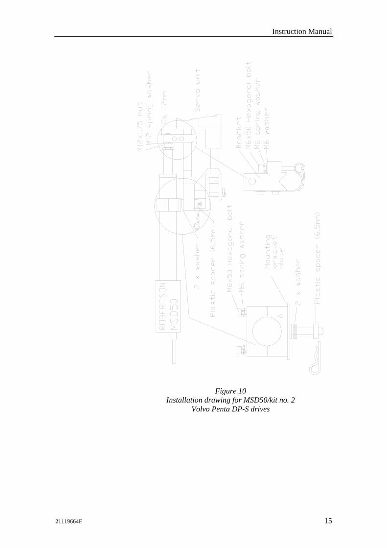
Figure 10
Installation drawing for MSD50/kit no. 2 Volvo Penta DP-S drives

Simrad MSD50 Mechanical Stern Drive
16 21119664F
Kit no. 3 (Mercruiser stern drive 93-96 gas engine)
Note The 93-96 model Mercruiser stern drive is identified by the casting mark (see Figure 12.)
Figure 11
MSD50 mounted to a 93-96 model Mercruiser stern drive with the Mercruiser kit no. 3 (see Figure 12 for details)
Installation instructions 1. Stern drive to midship position. 2. Remove the existing bolt from the position marked 1 (see
Figure 12). 3. MSD50 to midposition. Install the enclosed mounting kit
parts as shown. Place the plastic spacer and washers as shown on the drawing. Otherwise the unit will be damaged. Note that the kit includes three washers but only two are used for this installation.
4. Check the “rudder” movement from one side to the other. Be sure that the MSD50 is NOT acting as an endstop for the servo unit. It is also very important that the MSD50 and the mounting kit do not touch any part of the engine, steering system or other obstacles.
5. The MSD50 installation is subjected to large amounts of vibration. It is essential to ensure that all bolts are fully tightened. Retighten all bolts after the first seatrial.

Instruction Manual
21119664F 17
Figure 12 Installation drawing for MSD50/kit no. 3 on Mercruiser stern
drive, 93-96 gas/petrol engine

Simrad MSD50 Mechanical Stern Drive
18 21119664F
Kit no. 3 (Mercruiser stern drive 96- gas engine
Note The 96- model Mercruiser stern drive is identified by the casting mark (see Figure 14.)
Figure 13
MSD50 mounted to a 96- model Mercruiser stern drive with the Mercruiser kit no. 3 (See Figure 14 for details)
Installation instructions 1. Stern drive to midship position. 2. Remove the existing bolt from the position marked 1 (see
Figure 14). 3. MSD50 to midposition. Install the enclosed mounting kit
parts as shown. Place the washers as shown on the drawing. Otherwise the unit will be damaged. Note that the kit includes a plastic spacer that is not used for this installation.
4. Check the “rudder” movement from one side to the other. Be sure that the MSD50 is NOT acting as an end stop for the servo unit. It is also very important that the MSD50 and the mounting kit do not touch any part of the engine, steering system or other obstacles.
5. The MSD50 installation is subjected to large amounts of vibration. It is essential to ensure that all bolts are fully tightened. Retighten all bolts after the first sea trial.
Instruction Manual
21119664F 19
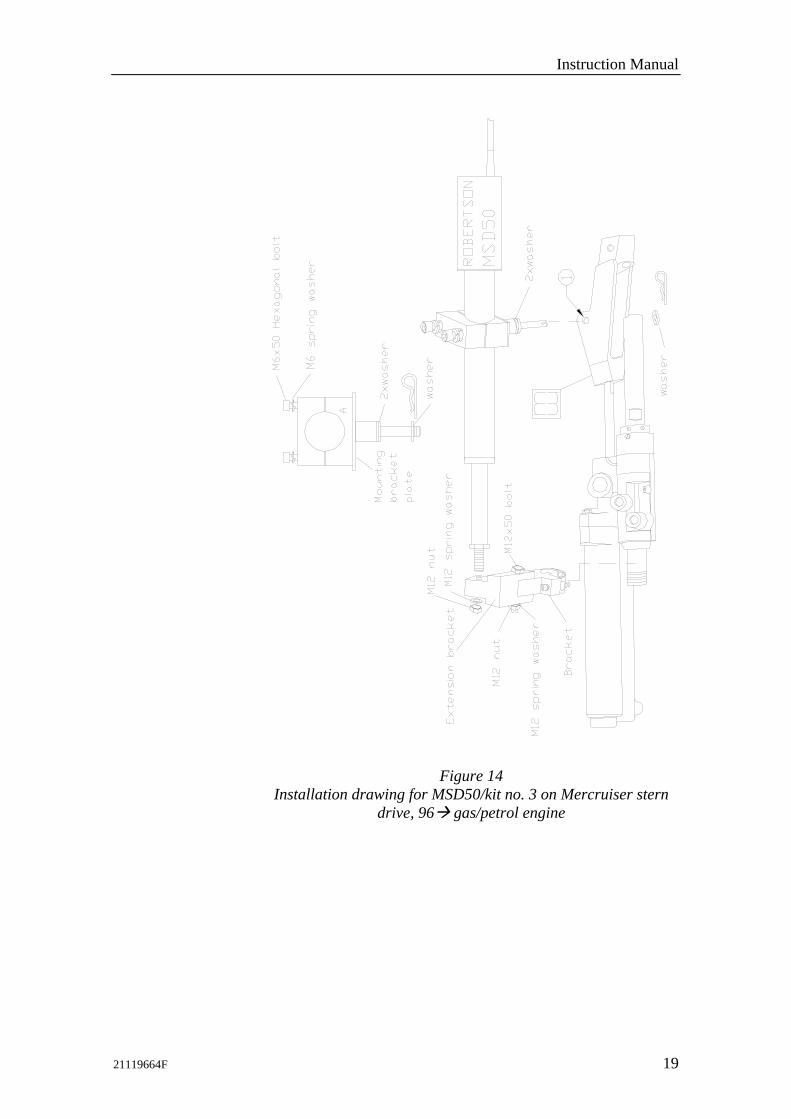
Figure 14 Installation drawing for MSD50/kit no. 3 on Mercruiser stern
drive, 96 gas/petrol engine

Simrad MSD50 Mechanical Stern Drive
20 21119664F
Kit no. 4 (Volvo Penta stern drive -41 series)
The MSD50 Volvo kit no. 4, part no. 21119755, for Volvo Penta stern drives can be used on the old Volvo Penta –41 series (up to -93). Installation instructions: 1. Stern drive to midship position. 2. MSD50 to midposition. Mount the enclosed installation kit
parts as shown on Figure 15 and Figure 16. Mount the main bracket with the clamp (B) so that the guide bars (D) enter on each side of the servo unit (H), (where the label is) and so that the clamp (B) flushes with the edge of (E). Tighten the two Allen screws on clamp (B).
3. Check the “rudder” movement from one side to the other. Be sure that the MSD50 is NOT acting as an end stop for the servo unit. It is also very important that the MSD50 and the mounting kit do not touch any part of the engine, steering system or other obstacles.
4. The MSD50 installation is subjected to large amounts of vibration. It is essential to ensure that all bolts are fully tightened. Retighten all bolts after the first sea trial.
Note At dual stern drive installation, use the dual installation fork (see Figure 16). Otherwise the installation is similar.
Figure 15
MSD50 mounted to an old Volvo Penta stern drive with Volvo mounting kit no. 4.

Instruction Manual
21119664F 21
Figure 16
Installation drawing for MSD50/kit no. 4 on old type Volvo stern drives

Simrad MSD50 Mechanical Stern Drive
22 21119664F
3.2 Electrical connection The MSD50 is supplied with a 7 meter, 6-wire cable. The cable carries current for the motor and clutch and supplies the feedback signal. It is connected to the AC10/AC20/AC40 autopilot computers or J3000X/ J300X junction units according to the diagram below.
Note The MSD50 requires a software in the J3xx junction unit that is version V1R4 or higher. Refer to the autopilot manual on how to verify the installed software at turn-on.
AUTOPILOT COMPUTER/JUNCTION UNIT
POWER PCBTB1 TB2 TB3 TB4 TB5
TB6
DriveEngage
Sol. -M
otor
Sol. -M
otor
TB7MSD50 MECHANICALSTERN DRIVE
MAIN PCB
RudderFeedb.
*
* NON POLARIZED(COLOUR INDEPENDENT)
RF +
RF
GR
EEN
YELLO
W
WH
ITEB
RO
WN
GR
EY
PIN
K
**
AUTOPILOT COMPUTER/JUNCTION UNIT
Figure 17
Connection diagram for MSD50
Note The cable screen must be connected to the ground terminal in the autopilot computer/junction unit.
3.3 Alignment
Note On stern drive installations the boat’s engine must be running at idle in order to perform the installation setup.
With the stern drive amidship and the MSD50 in its middle position, turn the wheel from lock to lock (HO - HO) and make sure that the stern drive hits the mechanical stops ("rudder stops") before the actuator reaches its utmost positions. The MSD50 has a relative feedback signal which needs a zero point setting after the autopilot has been turned on.
Perform the set-up in accordance with the autopilot manual. The MSD50 is a 12V drive unit.

Instruction Manual
21119664F 23
Identification dent
4 SPARE PARTS 44141562 Gear motor 21119409 MSD50 PCB ass’y
Note When ordering parts for the mounting kits, please refer to kit p/n and the encircled number for the actual part.
21119516 Mounting kit no. 1 (Drw. no. N3-111951A)
21119805 MSD50/KAD32 Adapter Bracket (See Figure 4)
21119656 Mounting kit no. 2 (Drw. no. N3-111965A)

Simrad MSD50 Mechanical Stern Drive
24 21119664F
21119672 Mounting kit no. 3 (Drw. no. N3-111970A)
21119755 Mounting kit no. 4 (Drw. no. N2-111975)