msd servo drive - moogsoftwaredownload.com ac fed drives sizes bg1 ... circuits not more than...
TRANSCRIPT

MSD Servo Drive product range
UL-Certification
moog
MSD Servo Drive

2MSD Servo Drive UL-CertificationID. No.: CC36842-001 Date: 05/2017
UL-Certification
Id No : CC36842-001, Rev. 1.0
Date: 05/2017
The content of our documentation was compiled with the greatest care and attention, and based on the latest information available to us.
We should nevertheless point out that this document cannot always be updated in line with ongoing technical developments in our products.
Information and specifcations may be subject to change at any time. For information on the latest version please visit [email protected].
moog
We reserve the right to make technical changes.

3MSD Servo Drive UL-CertificationID. No.: CC36842-001 Date: 05/2017
Content
1 MSD Servo Drive Product range .............................................. 51.1 MSD Servo Drive Compact UL certification .........................................................6
1.2 MSD Servo Drive Single-Axis System .................................................................8
1.2.1 AC fed drives sizes BG1 - BG4............................................................9
1.2.2 AC fed drives size BG5 ........................................................................10
1.2.3 AC fed drives size BG6 ........................................................................11
1.2.4 AC fed drives size BG7 ........................................................................12
1.3 MSD Servo Drive Multi-Axis System ...................................................................13
1.3.1 DC fed drives size BG1 - BG4 ............................................................14
1.3.2 DC fed drives size BG5 ......................................................................15
1.3.3 DC fed drives size BG6 ......................................................................16
1.3.4 DC fed drives size BG7 ......................................................................17
1.3.5 MSD Power Supply Unit (PSU) size 5 ..................................................18
1.3.6 MSD Power Supply Unit (PSU) size 6 ..................................................19
1.3.7 MSD Power Supply Unit (PSU) size 7 ..................................................20
moog

4MSD Servo Drive UL-CertificationID. No.: CC36842-001 Date: 05/2017
moog
5MSD Servo Drive UL-CertificationID. No.: CC36842-001 Date: 05/2017
MSD Servo Drive Product range
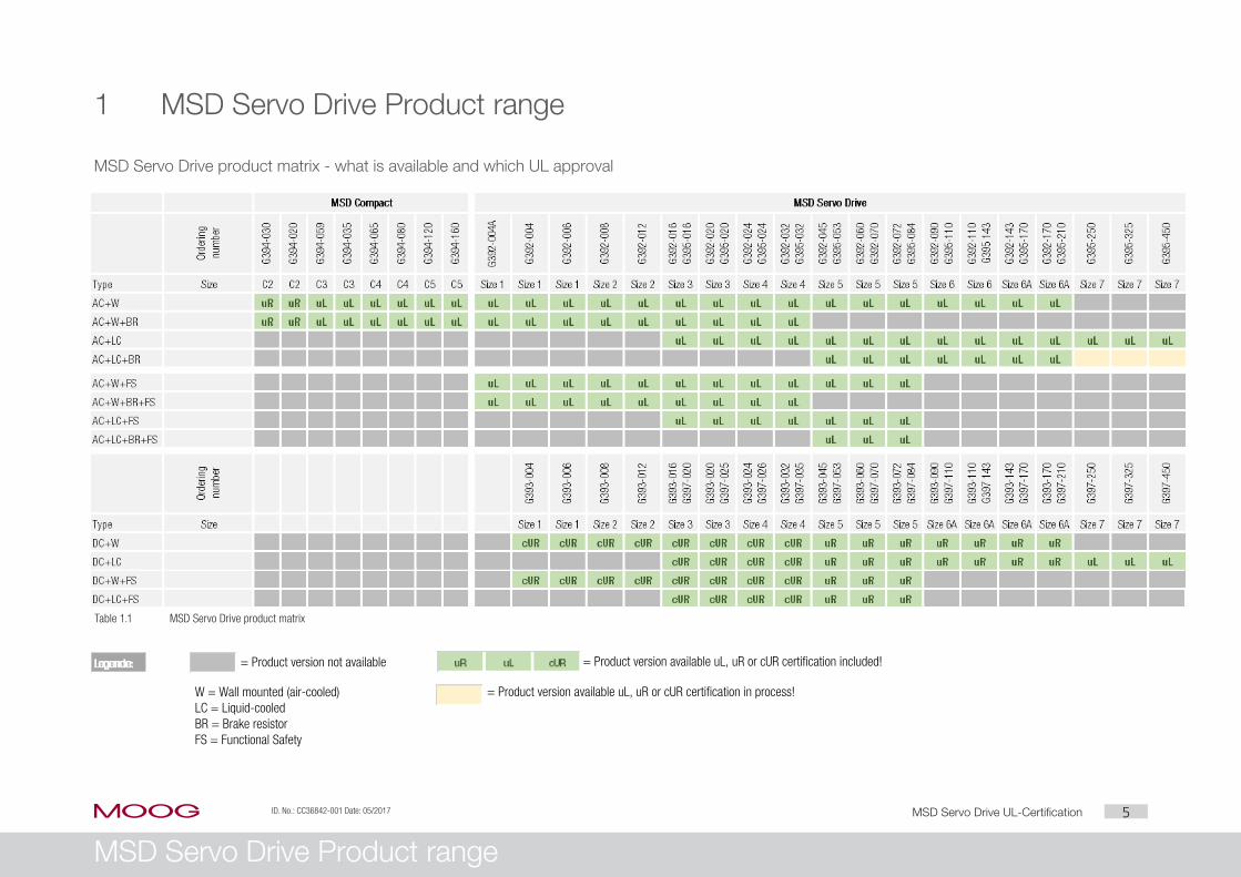
1 MSD Servo Drive Product range
MSD Servo Drive product matrix - what is available and which UL approval
Table 1.1 MSD Servo Drive product matrix
moog
= Product version not available = Product version available uL, uR or cUR certification included!
= Product version available uL, uR or cUR certification in process!W = Wall mounted (air-cooled)LC = Liquid-cooledBR = Brake resistorFS = Functional Safety

6MSD Servo Drive UL-CertificationID. No.: CC36842-001 Date: 05/2017
MSD Servo Drive Product range
Motor over temperature sensing (such as thermal sensor or switch embedded in the motor) must connected during operation of these drives.
In case the device is used in combination with an externally mounted brake resistor, over-temperature protection shall be provided separately to the brake resistor avoiding excessive temperatures.
Auxiliary supply voltage 24 Vdc.
For control outputs (OSDxx) use an isolated source only, rated 25 Vac or 24-30 Vdc as appropriate for rating of the given output.
A fuse in accordance with UL248 must be connected between the source and the output, rated 4 A/100 V.
Valid For all models MSD Servo Drive Compact with wall mounting air cooler in
combination with or without internal brake resistor.
For 3 x 230/400-480 V three-phase ac fed models only, max. 277 V RMS to ground.
Including all versions of communication interfaces and/or optional interfaces.
Functional safety models are not included.
Internal overload protection
The internal overload protection operates within maximum 10 sec seconds when reaching 200 % of the Motor Full Load Current. Details see in technical ratings appendix to instruction manual. Adjustment of internal overload protection see document “MSD Servo Drive Device Help”.
Special conditions for cold plate version The G394-030 and G394-020 (size BG2) are incomplete in construction and need an
external heatsink (cold plate version) at end-users application.
The external cooling must at least be equivalent to a steel plate with dimensions of 140 mm (5.51 in) by 490 mm (19.29 in), 3 mm (0.12 in) nominal thickness.
The temperature conditions shall be conducted in the end-use in situation when the products are going to be installed to a smaller plate/heatsink.
1.1 MSD Servo Drive Compact UL certification
Common terms to comply with the UL certification (UL508C) for all sizes MSD Servo Drive Compact
Multiple rated equipment. Operation only within the technical ratings of the drive, details see in technical ratings appendix instruction manual.
Ensure that surrounding air temperature does not exceed the maximum approbate ambient temperature, refer to model tables listed below.
For use only in electric supply mains with maximum overvoltage category III and for circuits not more than maximum short circuit current capability of symmetrical Amperes @ maximum voltage, when protected by fuses as required. Ratings and class refer to model tables listed below.
Integral solid state short circuit protection does not provide branch circuit protection. Branch circuit protection must be provided in accordance to the manufacturer instructions, National Electrical Code and any additional local codes.
Use in a pollution degree 2 environment according to IEC 60664-1 only. This means device shall be mounted in a suitable switchgear cabinet.
Use UL-certified device wiring (mains, motor and control cables) only
y
y
use copper conductors rated minimum +60/75 °C.
tightening torques for terminals, refer to model tables listed below.
moog
7MSD Servo Drive UL-CertificationID. No.: CC36842-001 Date: 05/2017
MSD Servo Drive Product range
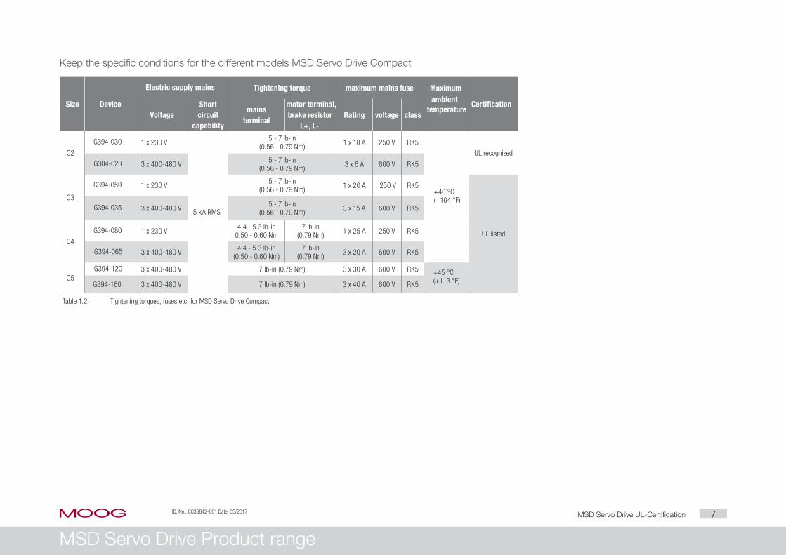
Keep the specific conditions for the different models MSD Servo Drive Compact
Size Device
Electric supply mains Tightening torque maximum mains fuse Maximum ambient
temperatureCertification
VoltageShort circuit
capability
mains terminal
motor terminal, brake resistor
L+, L-Rating voltage class
C2
G394-030 1 x 230 V
5 kA RMS
5 - 7 lb-in (0.56 - 0.79 Nm) 1 x 10 A 250 V RK5
+40 °C (+104 °F)
UL recognized
G304-020 3 x 400-480 V 5 - 7 lb-in (0.56 - 0.79 Nm) 3 x 6 A 600 V RK5
C3
G394-059 1 x 230 V 5 - 7 lb-in (0.56 - 0.79 Nm) 1 x 20 A 250 V RK5
UL listed
G394-035 3 x 400-480 V 5 - 7 lb-in (0.56 - 0.79 Nm) 3 x 15 A 600 V RK5
C4
G394-080 1 x 230 V 4.4 - 5.3 lb-in 0.50 - 0.60 Nm
7 lb-in (0.79 Nm) 1 x 25 A 250 V RK5
G394-065 3 x 400-480 V 4.4 - 5.3 lb-in (0.50 - 0.60 Nm)
7 lb-in (0.79 Nm) 3 x 20 A 600 V RK5
C5G394-120 3 x 400-480 V 7 lb-in (0.79 Nm) 3 x 30 A 600 V RK5 +45 °C
(+113 °F) G394-160 3 x 400-480 V 7 lb-in (0.79 Nm) 3 x 40 A 600 V RK5
Table 1.2 Tightening torques, fuses etc. for MSD Servo Drive Compact
moog

8MSD Servo Drive UL-CertificationID. No.: CC36842-001 Date: 05/2017
MSD Servo Drive Product range
1.2 MSD Servo Drive Single-Axis System
Common terms to comply with the UL certification (UL508C) for all the sizes MSD Servo Drive AC-AC
Multiple rated equipment. Operation only within the technical ratings of the drive, details see in technical ratings appendix instruction manual.
Ensure that surrounding air temperature does not exceed the maximum approbate ambient temperature, refer to model tables.
For use only in electric supply mains with maximum overvoltage category III and for circuits delivering not more than maximum short circuit current capability of symmetrical Amperes @ maximum voltage, when protected by fuses as required. Ratings and fuse classes refer to model tables listed below.
Integral solidstate short circuit protection does not provide branch circuit protection. Branch circuit protection must be provided in accordance to the manufacturer instructions, National Electrical Code and any additional local codes.
Use in a pollution degree 2 environment according to IEC 60664-1 only. This means device shall be mounted in a suitable switchgear cabinet.
Use UL-certified device wiring (mains, motor and control cables) only
y
y
use copper conductors rated min. +75 °C.
tightening torques for terminals, refer to model tables listed below.
Motor over temperature sensing (such as thermal sensor or switch embedded in the motor) must connected during operation of these drives.
In case the device is used in combination with an externally mounted brake resistor, over-temperature protection shall be provided separately to the brake resistor avoiding excessive temperatures.
Auxiliary supply voltage 24 Vdc.
For relay outputs (REL, RSH) on control board use an isolated source only, rated 24 Vdc.
A fuse in accordance with UL248 must be connected between the source and the output, rated 4 A.
moog
9MSD Servo Drive UL-CertificationID. No.: CC36842-001 Date: 05/2017
MSD Servo Drive Product range
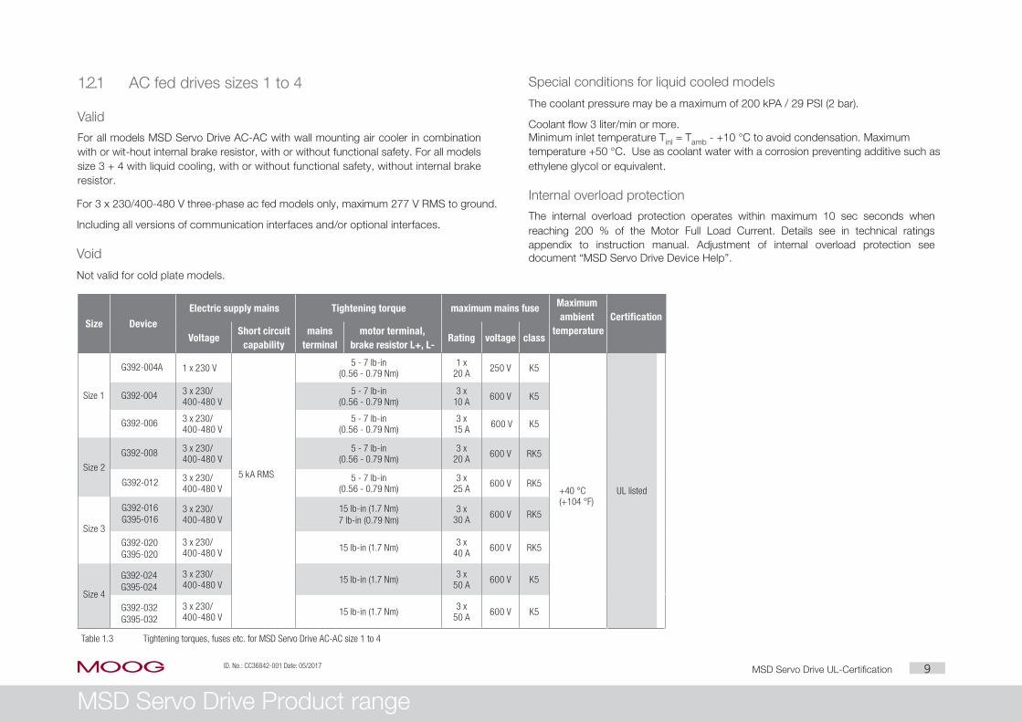
1.2.1 AC fed drives sizes 1 to 4
Valid
For all models MSD Servo Drive AC-AC with wall mounting air cooler in combination with or wit-hout internal brake resistor, with or without functional safety. For all models size 3 + 4 with liquid cooling, with or without functional safety, without internal brake resistor.
For 3 x 230/400-480 V three-phase ac fed models only, maximum 277 V RMS to ground.
Including all versions of communication interfaces and/or optional interfaces.
Void
Not valid for cold plate models.
Special conditions for liquid cooled models
The coolant pressure may be a maximum of 200 kPA / 29 PSI (2 bar).
Coolant flow 3 liter/min or more. Minimum inlet temperature Tinl = Tamb - +10 °C to avoid condensation. Maximum temperature +50 °C. Use as coolant water with a corrosion preventing additive such as ethylene glycol or equivalent.
Internal overload protection
The internal overload protection operates within maximum 10 sec seconds when reaching 200 % of the Motor Full Load Current. Details see in technical ratings appendix to instruction manual. Adjustment of internal overload protection see document “MSD Servo Drive Device Help”.
Size Device
Electric supply mains Tightening torque maximum mains fuse Maximum ambient
temperatureCertification
VoltageShort circuit
capabilitymains
terminalmotor terminal,
brake resistor L+, L-Rating voltage class
Size 1
G392-004A 1 x 230 V
5 kA RMS
5 - 7 lb-in (0.56 - 0.79 Nm)
1 x 20 A 250 V K5
+40 °C (+104 °F)
UL listed
G392-004 3 x 230/ 400-480 V
5 - 7 lb-in (0.56 - 0.79 Nm)
3 x 10 A 600 V K5
G392-006 3 x 230/ 400-480 V
5 - 7 lb-in (0.56 - 0.79 Nm)
3 x 15 A 600 V K5
Size 2
G392-008 3 x 230/ 400-480 V
5 - 7 lb-in (0.56 - 0.79 Nm)
3 x 20 A 600 V RK5
G392-012 3 x 230/ 400-480 V
5 - 7 lb-in (0.56 - 0.79 Nm)
3 x 25 A 600 V RK5
Size 3
G392-016G395-016
3 x 230/ 400-480 V
15 lb-in (1.7 Nm)7 lb-in (0.79 Nm)
3 x 30 A 600 V RK5
G392-020G395-020
3 x 230/ 400-480 V 15 lb-in (1.7 Nm) 3 x
40 A 600 V RK5
Size 4
G392-024G395-024
3 x 230/ 400-480 V 15 lb-in (1.7 Nm) 3 x
50 A 600 V K5
G392-032G395-032
3 x 230/ 400-480 V 15 lb-in (1.7 Nm) 3 x
50 A 600 V K5
Table 1.3 Tightening torques, fuses etc. for MSD Servo Drive AC-AC size 1 to 4
moog

10MSD Servo Drive UL-CertificationID. No.: CC36842-001 Date: 05/2017
MSD Servo Drive Product range
Use as coolant water with a corrosion preventing additive such as ethylene glycol or equivalant.
Internal overload protection
The internal overload protection operates within maximum 3 sec (30 sec for liquid cooled models) when reaching 200 % of the Motor Full Load Current. Details see in technical ratings appendix to instruction manual. Adjustment of internal overload protection see document “MSD Servo Drive Device Help”.
Keep the specific conditions for the different models MSD Servo Drive AC-AC size 5
Size Device
Electric supply mains Tightening torque maximum mains fuse Maximum ambient
temperatureCertification
VoltageShort circuit
capabilitymains
terminalmotor terminal,
brake resistor L+, L-Rating voltage class
Size 5
G392-045G395-053
3 x 230/ 400-480 V
10 kA RMS
22 lb-in (2.5 Nm) 3 x 50 A 600 V RK1
+40 °C (+104 °F)+45 °C (+113 °F) +55 °C (+131 °F) with derating
UL listedG392-060G395-070
3 x 230/ 400-480 V
22 lb-in (2.5 Nm) 3 x 80 A 600 V RK1
G392-072G395-084
3 x 230/ 400-480 V
22 lb-in (2.5 Nm) 3 x 80 A 600 V RK1
Table 1.4 Tightening torques, fuses etc. for MSD Servo Drive AC-AC size 5
1.2.2 AC fed drives size 5
Valid
For all models MSD Servo Drive AC-AC with wall mounting air cooler or liquid cooled models and in combination with or without internal brake resistors, with or without functional safety.
For 3 x 230/400-480 V three-phase ac fed models only, max. 277 V RMS to ground. Including all versions of communication interfaces and/or optional interfaces.
Void
Not valid for cold plate cooler models.
Special conditions for liquid cooled models
The coolant pressure may be a maximum of 200 kPA / 29 PSI (2 bar).
Coolant flow 8 or more liter/min. Minimum inlet temperature Tinl = Tamb - +10 °C to avoid condensation, maximum
temperature +50 °C.
moog

11MSD Servo Drive UL-CertificationID. No.: CC36842-001 Date: 05/2017
MSD Servo Drive Product range
1.2.3 AC-AC fed drives size 6 and 6A
Valid
For all models MSD Servo Drive AC-AC with wall mounting air cooler. All MSD Servo Drive AC-AC liquid cooled models and in combination with or without internal brake resistor.
For 3 x 230/400-480 V three-phase ac fed models only, max. 277 V RMS to ground. Including all versions of communication interfaces and/or optional interfaces.
Void
Not valid for Functional safety models.
All models MSD Servo Drive AC-AC with wall mounting air cooler and in combination with internal brake resistors.
Special conditions for liquid cooled models
The coolant pressure may be a maximum of 200 kPA / 29 PSI (2 bar).
Coolant flow 11-13 liter/min.
Minimum inlet temperature Tinl = Tamb - +10 °C to avoid condensation.
Use as coolant water with a corrosion preventive additive such as ethylene glycol or equivalant.
Internal overload protection
The internal overload protection operates within maximum 30 sec (10 sec for 143-210 A models) when reaching 200 % of the Motor Full Load Current. Details see in technical ratings appendix to instruction manual. Adjustment of internal overload protection see document “MSD Servo Drive Device Help”.
Keep the specific conditions for the different models MSD Servo Drive AC-AC size 6 and 6A type W or L
Size Device
Electric supply mains Tightening torque maximum mains fuse Maximum ambient
temperatureCertification
VoltageShort circuit
capabilitymains
terminalmotor terminal brake resistor Rating voltage class
Size 6
G392-090G395-110
3 x 230/ 400-480 V
10 kA RMS
88 - 177lb-in (10 - 20 Nm)
88 - 177lb-in (10 - 20 Nm)
53 - 70 lb-in (6 - 8 Nm) 3 x 100 A 600 V RK1
UL listed
G392-110G395-143
3 x 230/ 400-480 V
88 - 177lb-in (10 - 20 Nm)
88 - 177lb-in (10 - 20 Nm)
53 - 70 lb-in (6 - 8 Nm) 3 x 125 A 600 V RK1
G392-143G395-170
3 x 230/ 400-480 V
88 - 177lb-in (10 - 20 Nm)
132 - 265 lb-in (15 - 30 Nm)
53 - 70 lb-in (6 - 8 Nm) 3 x 175 A 600 V RK1
G392-170G395-210
3 x 230/ 400-480 V
88 - 177lb-in (10 - 20 Nm)
132 - 265 lb-in (15 - 30 Nm)
53 - 70 lb-in (6 - 8 Nm) 3 x 200 A 600 V RK1
Table 1.5 Tightening torques, fuses etc. for MSD Servo Drive AC-AC size 6
moog
+40 °C (+104 °F)+45 °C (+113 °F) +55 °C (+131 °F) with derating
Size 6A

12MSD Servo Drive UL-CertificationID. No.: CC36842-001 Date: 05/2017
MSD Servo Drive Product range
Use as coolant water with a corrosion preventive additive such as ethylene glycol or equivalant.
Special conditions for busbar terminals
Use properly sized UL listed ZMVV connector lugs and follow the instruction manual for proper wire sizes and installation or contact manufacturer to purchase proper lugs.
Internal overload protection
The internal overload protection operates within maximum 30 sec seconds when reaching 150 % of the Motor Full Load Current. Details see in technical ratings appendix to ins-truction manual. Adjustment of internal overload protection see document “MSD Servo Drive Device Help”.
Keep the specific conditions for the different models MSD Servo Drive AC-AC size 7 type W or L
Size Device
Electric supply mains Tightening torque maximum mains fuse Maximum ambient
temperatureCertification
VoltageShort circuit
capabilitymains
terminalmotor terminal brake resistor Rating voltage class
Size7
G395-250 3 x 400-480 V
30 kA RMS
Bus bar terminals M12 221 - 265 lb-in (25- 30 Nm)
Bus bar term. M10 177 - 221 lb-in (20 - 25 Nm) 3 x 250 A 600 V RK1
UL listedG395-325 3 x 400-480 V Bus bar terminals M12 221 - 265 lb-in (25- 30 Nm)
Bus bar term. M10 177 - 221 lb-in (20 - 25 Nm) 3 x 350 A 600 V RK1
G395-450 3 x 400-480 V Bus bar terminals M12 221 - 265 lb-in (25- 30 Nm)
Bus bar term. M10 177 - 221 lb-in (20 - 25 Nm) 3 x 450 A 600 V RK1
Table 1.6 Tightening torques, fuses etc. for MSD Servo Drive AC-AC size 7
1.2.4 AC-AC fed drives size 7
ValidFor all MSD Servo Drive AC-AC liquid cooled models.
For 3 x 400-480 V three-phase ac fed models only, max. 277 V RMS to ground.
Including all versions of communication interfaces and/or optional interfaces.
Void
Not valid for Functional safety models.
All models MSD Servo Drive AC-AC with wall mounting air cooler. All models in
combination with internal brake resistors.
Special conditions for liquid cooled models
The coolant pressure may be a maximum of 200 kPA / 29 PSI (2 bar). Coolant flow
12-14 liter/min.
Minimum inlet temperature Tinl = Tamb - +10 °C to avoid condensation.
moog
+40 °C (+104 °F)
13MSD Servo Drive UL-CertificationID. No.: CC36842-001 Date: 05/2017
MSD Servo Drive Product range
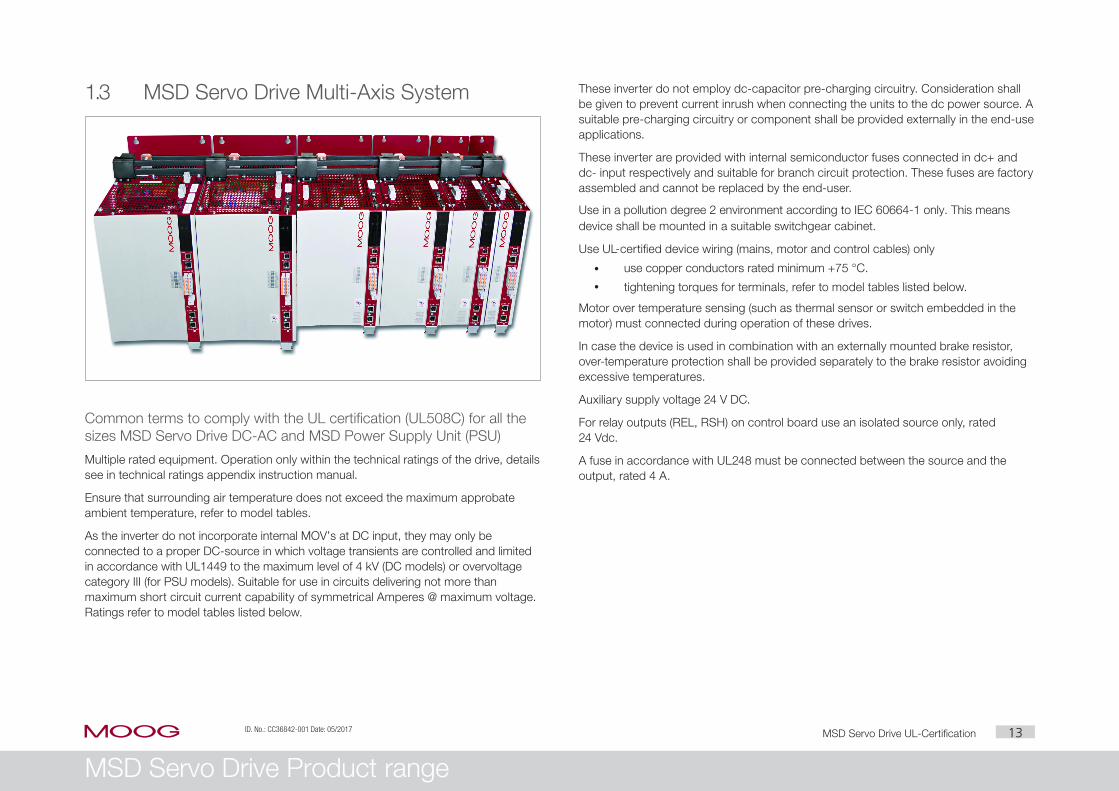
1.3 MSD Servo Drive Multi-Axis System
Common terms to comply with the UL certification (UL508C) for all the sizes MSD Servo Drive DC-AC and MSD Power Supply Unit (PSU)
Multiple rated equipment. Operation only within the technical ratings of the drive, details see in technical ratings appendix instruction manual.
Ensure that surrounding air temperature does not exceed the maximum approbate ambient temperature, refer to model tables.
As the inverter do not incorporate internal MOV’s at DC input, they may only be connected to a proper DC-source in which voltage transients are controlled and limited in accordance with UL1449 to the maximum level of 4 kV (DC models) or overvoltage category III (for PSU models). Suitable for use in circuits delivering not more than maximum short circuit current capability of symmetrical Amperes @ maximum voltage. Ratings refer to model tables listed below.
These inverter do not employ dc-capacitor pre-charging circuitry. Consideration shall be given to prevent current inrush when connecting the units to the dc power source. A suitable pre-charging circuitry or component shall be provided externally in the end-use applications.
These inverter are provided with internal semiconductor fuses connected in dc+ and dc- input respectively and suitable for branch circuit protection. These fuses are factory assembled and cannot be replaced by the end-user.
Use in a pollution degree 2 environment according to IEC 60664-1 only. This means device shall be mounted in a suitable switchgear cabinet.
Use UL-certified device wiring (mains, motor and control cables) only
y
y
use copper conductors rated minimum +75 °C.
tightening torques for terminals, refer to model tables listed below.
Motor over temperature sensing (such as thermal sensor or switch embedded in the motor) must connected during operation of these drives.
In case the device is used in combination with an externally mounted brake resistor, over-temperature protection shall be provided separately to the brake resistor avoiding excessive temperatures.
Auxiliary supply voltage 24 V DC.
For relay outputs (REL, RSH) on control board use an isolated source only, rated 24 Vdc.
A fuse in accordance with UL248 must be connected between the source and the output, rated 4 A.
moog

14MSD Servo Drive UL-CertificationID. No.: CC36842-001 Date: 05/2017
MSD Servo Drive Product range
Special conditions for liquid cooled models
The coolant pressure may be a maximum of 200 kPA / 29 PSI (2 bar).
Coolant flow 3 liter/min or more. Minimum inlet temperature Tinl = Tamb - +10 °C to avoid condensation, maximum temperature +50 °C.
Use as coolant water with a corrosion preventing additive such as ethylene glycol or equivalent.
Internal overload protection
The internal overload protection operates within maximum 30 sec or 10 sec when reaching 200 % of the motor full load current. Details see in technical ratings appendix to instruction manual. Adjustment of internal overload protection see document “MSD Servo Drive Device Help”.
Keep the specific conditions for the different models MSD Servo Drive DC-AC size 1 to 4
Size Device
Electric supply mains Tightening torque Maximum ambient
temperatureCertification
VoltageShort circuit
capabilityMains
terminalMotor terminal ,
brake resistor L+, L-
Size 1G393-004
565 - 770 V DC 5 kA RMS
5 -7 lb-in (0.56 - 0.79 Nm)
UL recognized and
CSA recognized
Size 2
Size 3
15 lb-in (1.7 Nm)7 lb-in (0.79 Nm)
G393-020G397-025
15 lb-in (1.7 Nm)Size 4
G393-024G397-026
Table 1.7 Tightening torques, overload protection etc. for MSD Servo Drive DC-AC size 1 to 4
1.3.1 DC fed drives size 1 to 4
Valid
For all models MSD Servo Drive DC-AC size 1 to 4 with wall mounting air cooler and for all models size 3 + 4 with liquid cooler. For all with or without functional safety and all without inter-nal brake resistor. For dc fed models only, maximum 770 V dc. Including all versions of communication interfaces and/or optional interfaces.
Void
Not valid for cold plate cooler models. Not valid for any combination with internal braking resistor.
moog
+40 °C (+104 °F)G393-016
G397-020
G393-032G397-035
G393-006
G393-008
G393-012

15MSD Servo Drive UL-CertificationID. No.: CC36842-001 Date: 05/2017
MSD Servo Drive Product range
1.3.2 DC fed drives size 5
Valid
For all models MSD Servo Drive DC-AC with wall mounting air cooler or liquid cooled models. For dc fed models only, maximum 770 V DC. Including all versions of communication interfaces and/or optional interfaces.
Void
Not valid for cold plate cooler models. Not valid for any combination with internal braking resistor.
Special conditions for liquid cooled models
The coolant pressure may be a maximum of 200 kPA / 29 PSI (2 bar).
Coolant flow 8-11 liter/min. Minimum inlet temperature Tinl = Tamb - +10 °C to avoid condensation, maximum temperature +50 °C.
Use as coolant water with a corrosion preventing additive such as ethylene glycol or equivalent.
Internal overload protection
The internal overload protection operates within maximum 3 sec (30 sec for liquid cooled models) when reaching 200 % of the motor full load current. Details see in technical ratings appendix to instruction manual. Adjustment of internal overload protection see document “MSD Servo Drive Device Help”.
Keep the specific conditions for the different models MSD Servo Drive DC-AC size 5
Size Cooler type Device
Electric supply mainsOverload
protection
Tightening torque Maximum ambient
temperatureCertification
VoltageShort circuit
capabilityDC input terminal
motor terminal
Size 5
Wwall mounting air cooler
G393-045 770 V DC
5 kA DC 200 % @ 3 sec 22 - 39,8 lb-in (2.5 - 4.5 Nm) 40 lb-in (4.5 Nm)
UL recognized
770 V DC
770 V DC
L liquid cooler
G397-053 770 V DC
10 kA DC 200 % @ 30 sec 22 - 39,8 lb-in (2.5 - 4.5 Nm) 40 lb-in (4.5 Nm)770 V DC
770 V DC
Table 1.8 Tightening torques, overload protection etc. for MSD Servo Drive DC-AC size 5
moog
G393-060
G393-072
G397-070
G397-084
+40 °C (+104 °F)

16MSD Servo Drive UL-CertificationID. No.: CC36842-001 Date: 05/2017
MSD Servo Drive Product range
Special conditions for liquid cooled models
The coolant pressure may be a maximum of 200 kPA / 29 PSI (2 bar).
Coolant flow 11 - 13 liter/min. Minimum inlet temperature Tinl = Tamb - +10 °C to avoid condensation.
Use as coolant water with a corrosion preventing additive such as ethylene glycol or equivalent.
Internal overload protection
The internal overload protection operates within maximum 30 sec or 10 sec when reaching 200 % of the motor full load current. Details see in technical ratings appendix to inst-ruction manual. Adjustment of internal overload protection see document “MSD Servo Drive Device Help”.
Keep the specific conditions for the different models MSD Servo Drive DC-AC size 6A
Size Cooler type Device
Electric supply mainsOverloadprotection
Tightening torque
CertificationVoltage
Short circuit capability
DC input terminal
motor terminal
Size 6A
W + Lwall mounting air cooler
and liquid cooler
G393-090G397-110
770 V DC
10 kA DC
200 % @ 30 sec
175 lb-in (20 Nm)
177 lb-in (20 Nm)
UL recognized
G393-110G397-143
770 V DC
G393-143G397-170
770 V DC
200 % @ 10 sec 270 lb-in (30 Nm)G393-170G397-210
770 V DC
Table 1.9 Tightening torques, overload protection etc. for MSD Servo Drive DC-AC size 6
1.3.3 DC fed drives size 6A
Valid
For all models MSD Servo Drive DC-AC with wall mounting air cooler or liquid cooled models. For dc fed models only, maximum 770 V dc. Including all versions of communication interfaces and/or optional interfaces.
Void
Not valid for Functional safety models. Not valid for cold plate cooler models. Not valid for any combination with internal braking resistor
moog
Maximum ambient
temperature
+40 °C (+104 °F)

17MSD Servo Drive UL-CertificationID. No.: CC36842-001 Date: 05/2017
MSD Servo Drive Product range
1.3.4 DC fed drives size 7
Valid
For all MSD Servo Drive DC-AC liquid cooled models.
For DC fed models only, maximum 770 V DC. To be supplied by Moog AC Drive Models G395-450 only.
Including all versions of communication interfaces and/or optional interfaces.
Void
Not valid for Functional safety models.
All models MSD Servo Drive DC-AC with wall mounting air cooler. All models in
combination with internal brake resistors.
Special conditions for liquid cooled models
The coolant pressure may be a maximum of 200 kPA / 29 PSI (2 bar).
Coolant flow 12-14 liter/min. Minimum inlet temperature Tinl = Tamb - +10 °C to avoid condensation.
Use as coolant water with a corrosion preventing additive such as ethylene glycol or equivalent.
Special conditions for busbar terminals
Use properly sized UL listed ZMVV connector lugs and follow the instruction manual for proper wire sizes and installation or contact manufacturer to purchase proper lugs.
Internal overload protection
The internal overload protection operates within maximum 30 sec seconds when reaching 150 % of the Motor Full Load Current. Details see in technical ratings appendix to ins-truction manual. Adjustment of internal overload protection see document “MSD Servo Drive Device Help”.
Keep the specific conditions for the different models MSD Servo Drive DC-AC size 7 type W or L
Size Cooler type Device
Electric supply mainsOverload
protection
Tightening torque maximum mains fuse
CertificationVoltage
Short circuit capability
Main terminal
Motor terminal
Brake resistor Rating VoltageType (manufacturer
Mersen)
Size 7L
liquid cooler
G397-250 770 V DC
30 kA DC 150 % @ 30 sec
Bus bar terminals M12 221 - 265 lb-in (20 - 25 Nm)
M10 177 - 221 lb-in (20 - 25 Nm)
2 x 400 A
700 V DC
A70QS400-4 or -4k
+45 °C (+113 °F) UL listed770 V DC 2 x 400 A A70QS400-4 or -4k
G397-450 770 V DC 3 x 600 A A70QS600-4 or -4k
Table 1.10 Tightening torques, overload protection etc. for MSD Servo Drive DC-AC size 7
moog
Maximum ambient
temperature
G397-325

18MSD Servo Drive UL-CertificationID. No.: CC36842-001 Date: 05/2017
MSD Servo Drive Product range
Special conditions for liquid cooled models
The coolant pressure may be a maximum of 200 kPA / 29 PSI (2 bar).
Coolant flow 8-11 liter/min.
Minimum inlet temperature Tinl = Tamb - +10 °C to avoid condensation.
Use as coolant water with a corrosion preventing additive such as ethylene glycol or equivalent.
Keep the specific conditions for the different models MSD Power Supply Unit size 5
Size Device
Mains voltage Tightening torque maximum mains fuse
CertificationVoltage
Short circuit capability
Main terminal
DC output terminal
Rating Voltage class
Size 5G396-026 3 x 400-480 V 5 kA RMS 40 lb-in
(4.5 Nm)22 - 39.8 lb-in(2.5 - 4.5 Nm)
3 x 100 A600 V RK1 UL
recognized3 x 400-480 V 10 kA RMS 3 x 100 A
Table 1.11 Tightening torques, fuses etc. for MSD Power Supply Unit size 5
1.3.5 MSD Power Supply Unit (PSU) size 5
Valid
For all models MSD Power Supply Unit with wall mounting air cooler or liquid cooled models and in combination with internal brake resistors.
For 3 x 400-480 V three phase ac models only, maximum 277 V RMS to ground. Including all versions of communication interfaces and/or optional interfaces. The recommended line connection sets (filter choke, set-up choke and mains filter) shall be used.
Void
Not valid for Functional safety models, cold plate cooler models.
moog
G396-050
Maximum ambient
temperature
+40 °C (+104 °F)

19MSD Servo Drive UL-CertificationID. No.: CC36842-001 Date: 05/2017
MSD Servo Drive Product range
1.3.6 MSD Power Supply Unit (PSU) size 6
Valid
For all models MSD Power Supply Unit with wall mounting air cooler or liquid cooled models and in combination with internal brake resistors.
For 3 x 400-480 V three phase ac models only, maximum 277 V RMS to ground. Including all versions of communication interfaces and/or optional interfaces. The recommended line connection sets (filter choke, set-up choke and mains filter) shall be used.
Void
Not valid for Functional safety models, push through models.
Special conditions for liquid cooled models
The coolant pressure may be a maximum of 200 kPA / 29 PSI (2 bar).
Coolant flow 11-13 liter/min.
Minimum inlet temperature Tinl = Tamb - +10 °C to avoid condensation.
Use as coolant water with a corrosion preventing additive such as ethylene glycol or equivalent.
Keep the specific conditions for the different models MSD Power Supply Unit size 6A
Size DeviceMains voltage Tightening torque maximum mains fuse
CertificationVoltage
Short circuit capability
Main terminal
DC output terminal
Rating Voltage class
Size 6AG396-075 3 x 400-480 V 10 kA RMS 270 lb-in
(30 Nm)175 lb-in(20 Nm)
3 x 200 A600 V RK1 UL recognized
G396-110 3 x 400-480 V 10 kA RMS 3 x 200 A
Table 1.12 Tightening torques, fuses etc. for MSD Power Supply Unit size 6
moog
Maximum ambient
temperature
+40 °C (+104 °F)

20MSD Servo Drive UL-CertificationID. No.: CC36842-001 Date: 05/2017
MSD Servo Drive Product range
1.3.7 MSD Power Supply Unit (PSU) size 7
Currently no UL Certification for MSD Power Supply Unit size 7 available!
moog


TAKE A CLOSER LOOK.
Moog solutions are only a click away. Visit our worldwide Web site for more
information and the Moog facility nearest you.
moog
Moog GmbH Hanns-Klemm-Straße 28 D-71034 Böblingen Phone +49 7031 622 0 Telefax +49 7031 622 100
www.moog.com/industrial [email protected]
Moog is a registered trademark of Moog, Inc. and its subsidiaries. All quoted trademarks are property of Moog, Inc. and its subsidiaries. All rights reserved. © 2017 Moog, Inc.
Technical alterations reserved.
The contents of our documentation have been compiled with greatest care and in compliance with our present status of information.
Nevertheless we would like to point out that this document cannot always be updated parallel to the technical further development of our products.
Information and specifications may be changed at any time. For information on the latestversion please refer to [email protected].
ID no.: CC36842-001, Rev. 1.0 Date: 05/2017