m.saleem khan, khaled benkrid - iaeng · m.saleem khan, khaled benkrid ... the integrated control...
TRANSCRIPT

M.Saleem Khan, Khaled Benkrid
Proceedings of the International MultiConference of Engineers and Computer Scientists 2009 Vol IIIMECS 2009, March 18 - 20, 2009, Hong Kong
ISBN: 978-988-17012-7-5 IMECS 2009

II. ADVANCED TRAIN CONTROL SYSTEMS EVOLUTION
The development to enhance the capabilities of the train control
systems is under progress at various platforms.
The evolution of train control methods, key functional
requirements including location determination, detection,
monitoring, autonomous control, data communication systems,
Global Positioning System (GPS) and information processing
are the main issues to review the existing train control system
technology. In order to enhance safety of train operations new
autonomous technology is needed to replace the existing
systems [11]. Various architectures and methodologies for
executing a train control in safe manner are being tested for
implementation [12]
The open system interconnection-OSI model for radio data link
communication to vehicle tracking and operational
requirements has been suggested [13], [14]. A strategy for
designing a network management system is required.
Applications of modern command control and communication
technology are required for Advanced Train Control
System-ATCS [15],[16]. The existing systems need the unified
operations in central traffic control with multi sensors
conditions monitoring systems, position information systems
including transponders and satellite for a two way digital
communications network covering rail road, way side switch,
detector interfaces and powerful central computer systems
[17].The study of railway system with the problem of evaluating
the benefits of safety enhancement to avoid rare but
catastrophic accidents revealed that advanced train protection
systems should have been installed [18].
The integrated control features of automatic train technology
being in process, are the continuous communications-signaling
system to update the driver’s limit of authority, train location
and route data transmitted to train from track transponders,
automatic train protection for full speed, limit of authority
supervision and computer based train control systems with real
time train scheduling capability [19].
III. THE REQUIREMENTS OF THE PROPOSED SYSTEM AND THE INITIAL
ADJUSTMENTS
In this section, the overall structural requirements of the system
are discussed. The proposed system is based on: the starting
adjustments; initial time, starting station, information about
passengers, complete root chart loading, and with all the
utilities, observations; junction track change information,
crossing gate information, track clearance, track condition,
environment monitoring, request from non-stop stations,
vehicle to vehicle, and vehicle to control room communication
facilities. autonomous decisions and operations; time, distance,
and speed measurements, speed scheduling , management and
control
A. Internet Access and Communication System
A railway Internet communication system can combine a
bidirectional satellite link with a distributed system (wireless
LAN and optical fibre) on the train. The train running up to 350
km/h needs at least 4 M bits/s in downlink and 2M bits/s in
uplink data rates with a GEO stationary satellite.
The system is composed of a communication subsystem, a
pointing subsystem and a distribution subsystem. The
communication subsystem possesses the Antenna, Transmitter,
Modem, and router IP connectivity.
The pointing subsystem performs the satellite acquisition and
tracking. In order to maximize the received or transmitted
signal, several elements like IMU-Inertial measurement unit,
AGC (automatic gain control) and control unit are required. The
distribution subsystem possesses the optical fibre connection
between the central server and each train car for signal
distribution to the passengers [5].
B. Internet Utilities to Passengers
Via the internet the passengers with prepaid cards can be
provided a username and password to log on to the system to get
web access, voice over IP connectivity and email services. Via
railway operator’s Internet they can avail of on line games, trip
maps and facts, ticket reservations and sales, video streaming
and electronic newspapers.
C. Close Circuit Television (CCTV)
IP-based video surveillance system can record picture on the
train to be monitored by staff in centralised control room to
counteract anti-social activities.
D. Railway Measurement System
This system implements real time telemetry services for the
railway system using the information of equipments for rail
wheels, acceleration on train axles, vibrations, monitoring the
signals of junction track information JTI, crossing gates CG,
track condition TC, track clearance TCL, Request from
non-stop stations, mileage record MR, environment monitoring
EM, vehicle tilting VT, on track vehicle to vehicle and between
vehicle and main control information exchange. This
information is help full for vehicle speed control and scheduling
[7].The loaded information of the root chart in the system is
according to the prerequisite conditions for a particular track.
This information is used in speed control and scheduling. At the
starting point, pre-loaded information about vehicle root is
selected or other information is allowed to be loaded into the
system memory by the control room. The manual entry is also
allowed with the authentication of the operator identification.
This initial information includes the start time, speed schedule,
position of stopping stations, locations of junction track change
and crossing gates and track condition
IV. OVER ALL STRUCTURE OF THE PROPOSED RAILWAY VEHICLE
CONTROL SYSTEM- RVCS
The proposed system is able to receive the information
regarding the request to/from non-stop stations, position,
velocity and actual distance covered from mileage record. The
position, velocity and mileage records help for error correction
in speed adjustment. The speed scheduling and management
arrangement is shown in Fig. 1. The overall speed control and
adjustment are shown in Fig. 2.
The block scheme of the whole system is shown in Figure 3.
Proceedings of the International MultiConference of Engineers and Computer Scientists 2009 Vol IIIMECS 2009, March 18 - 20, 2009, Hong Kong
ISBN: 978-988-17012-7-5 IMECS 2009
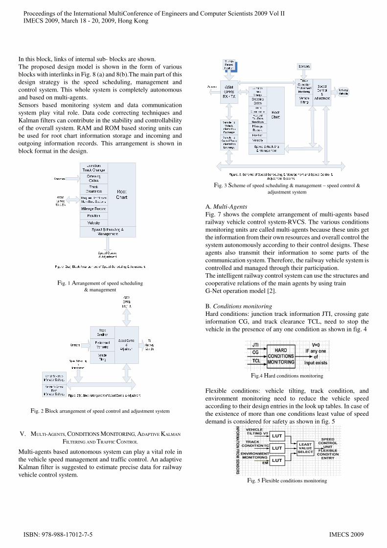
In this block, links of internal sub- blocks are shown.
The proposed design model is shown in the form of various
blocks with interlinks in Fig. 8 (a) and 8(b).The main part of this
design strategy is the speed scheduling, management and
control system. This whole system is completely autonomous
and based on multi-agents.
Sensors based monitoring system and data communication
system play vital role. Data code correcting techniques and
Kalman filters can contribute in the stability and controllability
of the overall system. RAM and ROM based storing units can
be used for root chart information storage and incoming and
outgoing information records. This arrangement is shown in
block format in the design.
Fig. 1 Arrangement of speed scheduling
& management
Fig. 2 Block arrangement of speed control and adjustment system
V. MULTI-AGENTS, CONDITIONS MONITORING, ADAPTIVE KALMAN
FILTERING AND TRAFFIC CONTROL
Multi-agents based autonomous system can play a vital role in
the vehicle speed management and traffic control. An adaptive
Kalman filter is suggested to estimate precise data for railway
vehicle control system.
Fig. 3 Scheme of speed scheduling & management – speed control &
adjustment system
A. Multi-Agents
Fig. 7 shows the complete arrangement of multi-agents based
railway vehicle control system-RVCS. The various conditions
monitoring units are called multi-agents because these units get
the information from their own resources and overall control the
system autonomously according to their control designs. These
agents also transmit their information to some parts of the
communication system. Therefore, the railway vehicle system is
controlled and managed through their participation.
The intelligent railway control system can use the structures and
cooperative relations of the main agents by using train
G-Net operation model [2].
B. Conditions monitoring
Hard conditions: junction track information JTI, crossing gate
information CG, and track clearance TCL, need to stop the
vehicle in the presence of any one condition as shown in fig. 4
Fig.4 Hard conditions monitoring
Flexible conditions: vehicle tilting, track condition, and
environment monitoring need to reduce the vehicle speed
according to their design entries in the look up tables. In case of
the existence of more than one conditions least value of speed
demand is considered for safety as shown in fig. 5
Fig. 5 Flexible conditions monitoring
Proceedings of the International MultiConference of Engineers and Computer Scientists 2009 Vol IIIMECS 2009, March 18 - 20, 2009, Hong Kong
ISBN: 978-988-17012-7-5 IMECS 2009

C. Adaptive Kalman Filtering
This whole proposed system of railway vehicle is based on the
communicated information. The delivery of precise data is
highly recommended for the stability and controllability of the
system. The vehicle to vehicle and between vehicle and control
room, information management units are used to control the
speed of railway vehicle. In this arrangement track condition,
environment monitoring and vehicle tilting monitoring systems
are designed to control the system. In order to avoid data losses
and noise, Kalman filters are the best option to be used at the
receiving end of the system [6].
D. Traffic Control
For the vehicular traffic control on a track or on adjacent tracks
joining at junction, conditions for normal traffic or rear-end
collision must be examined.
A mathematical modular approach is proposed for the safe
vehicle speed adjustment to reduce any time delay due to any
reason i.e. JTC, TC, CG etc in the journey.
The characteristics of mathematical formulation for normal
vehicle traffic encountered in practice are proposed for the
proper speed control and adjustment. The characteristic
behavior for normal traffic is adapted in the final speed
calculations on the basis of vehicle to vehicle and vehicle to
control room communication in distributed environment.
If vehicles A, B and C are in first, second and third order, their
speeds arrangement for normal traffic system should be
maintain as VC ≤ VB ≤ VA.
The vehicle in front can start and move with the maximum
speed on empty track but the following trains behind the first
one will adjust their speed within certain limit to recover their
time delay [4].The possible ways to increase the speed and
improve the synchronisation of trains are required to be adopted
for the stability of railway networks [10].
This model has the capacity through its speed scheduling unit to
include the consideration about random delays of trains and the
propagation of delay across the network. This discussion shows
that the final speed adjustment in these types of special cases
requires the information exchange between vehicles in
automation, and another option proposed to be used is to mount
high quality SONOR sensors at the front and rear ends of the
vehicle to collect the information for the speed estimation. The
speed control unit block is shown in fig.6.
Fig. 6 Speed control block
For this part of the circuit, Kalman filters play the vital roles in
data estimation for proper speed adjustments. This information
should be accurate and without any noise or delay. The
mechatronics uses the electronics components and tools
together with the mechanical systems. High-tech electronics is
increasingly being used to develop such systems in automation
but the low cost solutions for the specific tasks need to be
developed [2]. In this regard, FPGAs are playing a significant
role to develop high performance circuits with the added
re-programmable feature [20]
VI. DESIGN MODEL BLOCKS- DESCRIPTION
This proposed design of multi-agents based RVCS has the
complete autonomy to handle the issues related with the desired
root chart travel, various conditions monitoring and speed
adjustment, vehicle speed scheduling, management and control,
maintain to store the record history of all the information during
travel as a black box, vehicle motor power control and motor
drive and the provision of communication between main control
room and others vehicles on track. It is also capable to receive
the information regarding junction track change, crossing gates
status, travelled distance mileage, global positioning, speed and
request from non-stop stations. In this design the whole system
is spread in 16 blocks.
BLOCK-1 consists of two RAMs to store the 2 tracks root chart
information loaded at the starting station. One of the
information is regarding the current root, while another entry is
about the root which may be adapted in transit or after the first
root as a provision. The entry may be through communication or
by manual means. RAM-1 or RAM-2 can be enabled by the data
entry selection from block 2. Memory address bus is common
for blocks 1 & 3 and provided by memory address counter-1
from block 2.
BLOCK-2 gives the provision of memory selection for a
particular track and data entry. Its root selection unit enables the
ROMs in Block 3 and provides the address for memories used.
BLOCK-3 uses 4- ROMs to have the pre-loaded 4 tracks root
chart information. Any one of these 4 roots can be selected
through Block 2. The common address is provided by Block
2.The data output lines are common and connected with
common root chart memory information bus.
BLOCK-4 is for hard conditions monitoring and decision about
halt. It receives the three information: junction track-JTI,
crossing gates-CG and track clearance-TCL. JTI and CG may
be received through communication system and TCL through
SONOR sensors mounted at the front and rear ends of the train.
These signals are conditioned and processed for the decision of
halt through hard condition decision logic unit. The output of
this unit is fed to Block5 for record and Block8 for speed
scheduling, management and control.
BLOCK-5 is for hard condition record. It uses RAM-7 and
address counter with clock enable when new entry comes. The
output of RAM-7 is connected with Block13 for black box
entry.
Proceedings of the International MultiConference of Engineers and Computer Scientists 2009 Vol IIIMECS 2009, March 18 - 20, 2009, Hong Kong
ISBN: 978-988-17012-7-5 IMECS 2009
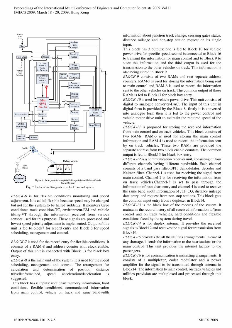
Fig. 7 Links of multi-agents in vehicle control system
BLOCK-6 is for flexible conditions monitoring and speed
adjustment. It is called flexible because speed may be changed
but not for the system to be halted suddenly. It monitors three
conditions: track condition-TC, environment-EM and vehicle
tilting-VT through the information received from various
sensors used for this purpose. These signals are processed and
lowest speed priority adjustment is implemented. Output of this
unit is fed to block7 for record entry and Block 8 for speed
scheduling, management and control.
BLOCK-7 is used for the record entry for flexible conditions. It
consists of a RAM-8 and address counter with clock enable.
Output of this unit is connected with Block 13 for black box
entry.
BLOCK-8 is the main unit of the system. It is used for the speed
scheduling, management and control. The arrangement for
calculation and determination of position, distance
travelled/remained, speed, acceleration/deceleration is
suggested.
This block has 6 inputs: root chart memory information, hard
conditions, flexible conditions, communicated information
from main control, vehicle on track and same bandwidth
information about junction track change, crossing gates status,
distance mileage and non-stop station request on its single
input.
This block has 3 outputs: one is fed to Block 10 for vehicle
power drive for specific speed, second is connected to Block 16
to transmit the information for main control and to Block 9 to
store this information and the third output is used for the
transmission to the other vehicles on track. This information is
also being stored in Block 9.
BLOCK-9 consists of two RAMs and two separate address
counters. RAM-5 is used for storing the information being sent
to main control and RAM-6 is used to record the information
sent to the other vehicles on track. The common output of these
RAMs is fed to Block13 for black box entry.
BLOCK-10 is used for vehicle power drive. This unit consists of
digital to analogue converter-DAC. The input of this unit in
digital form is provided by the Block 8, firstly it is converted
into analogue form then it is fed to the power control and
vehicle motor drive unit to maintain the required speed of the
vehicle.
BLOCK-11 is proposed for storing the received information
from main control and on track vehicles. This block consists of
two RAMs. RAM-3 is used for storing the main control
information and RAM-4 is used to record the information sent
by on track vehicles. These two RAMs are provided the
separate address from two clock enable counters. The common
output is fed to Block13 for black box entry.
BLOCK-12 is a communication receiver unit, consisting of four
different channels having different bandwidth. Each channel
consists of a band pass filter-BPF, demodulator, decoder and
Kalman filter. Channel-1 is used for receiving the signal from
main control. Channel-2 is for receiving the information from
on track vehicles.Channel-3 is set to pass through the
information of root chart entry and channel-4 is used to receive
the same band width information of JTI, CG, distance mileage
data entry, and request from non-stop stations. This block gets
the common input entry from a duplexer in Block14.
BLOCK-13 is the black box of the records of the system. It
maintains the record history of all received information to/from
control and on track vehicles, hard conditions and flexible
conditions faced by the system during travel.
BLOCK-14 is for duplex antenna. It provides the received
signals to Block12 and receives the signal for transmission from
Block16.
BLOCK-15 provides the all the utilities arrangements. In case of
any shortage, it sends the information to the near stations or the
main control. This unit provides the internet facility to the
passengers.
BLOCK-16 is for communication transmitting arrangements. It
consists of a multiplexer, coder modulator and a power
amplifier for the signal to be transmitted through antenna in
Block14. The information to main control, on track vehicles and
utilities provision are multiplexed and processed through this
block.
.
Proceedings of the International MultiConference of Engineers and Computer Scientists 2009 Vol IIIMECS 2009, March 18 - 20, 2009, Hong Kong
ISBN: 978-988-17012-7-5 IMECS 2009

VII. CONCLUSION AND FUTURE WORK
This work provides the vision of highly accurate system for the
autonomous control of railway vehicles. This design model can
easily be changed for memory expansion and can be
implemented using high state of the art microelectronic
technology with accuracy and stability as forefront goals. As the
system is based on heavy information communication, therefore
proper coding and filtering techniques need to be exercised.
Fig. 8(a) Design blocks of the proposed railway vehicle control system-
RVCS
REFERENCES
[1] R.Harrison,S. M.Lee,”Reconfigurable modular automation systems for
automotive power-train manufacturer”,Int Flex Manuf Syst
(2006),18:175-190,Springer Science 1March 2007.
[2] Yangdong Ye,Lei Zhang,”Research on agent based G-Net train group
operation model”, World congress on intelligent control and
automation 2004.
[3] Ayers, R. G. “Selection of a Forward Error Correcting Code for the Data Communications Radio Link of the Advanced Train Control System”. ARINC Research Corp, Annapolis, MD, U.S. Proceedings of the 1988 Joint ASME-IEEE
[4] Diran Basmadjian,”The Art of Modeling In Science and Engineering”
Chapman & Hall/CRC, 1999. [5] ACORDE-“Broadband Railway Internet Access on High Speed Trains
via Satellite Links”, on web sitwhttp://www.railway- technology.com
[6] Simon Haykin,”Adaptive Filter Theory”,Pearson,2003
[7] Ben Schiller,”Model Approach to Running a Railway” FT.com print
article, 8June 2008, web site http://www.ft. com,
[8] Sheikh, Asrar U.; Kraav, J.; Marcos, W. “Mobile Data Link Field Trials: An Evaluation for ATCS”. 38th IEEE Vehicular
Technology Conference. Philadelphia, PA, U.S.,1988
[9] Stefano Bruni, T .X. Mei, ”Control and Monitoring for Railway Vehicle
Dynamics”,Vehicle System Dynamics,vol.45, NO. 7-8,July-August
2007, 743-779
[10] O.Engelhart-Funke,”Analysing stability and investments in railway
networks using advanced evolutionary algorithms”,Int. Trans.
Oper.Res,vol11,No.4,p381-94,July(2004)
[11] George Achakji, 22a Review of state-of-the Art Train Control System
Technology”, Transportation Development Centre. Canada.TP 13105E,
March1998.
[12] Ghosh, Anup K, “Distributed Safety-critical System for Real-time
Train Control”, U.S. Proceedings of the 1995 IEEE 21st
International Conference on Industrial Electronics, Control, and
Instrumentation
[13] Coll, David C, “Communications System Architecture of the North American Advanced Train Control System”. IEEE Transactions on Vehicular Technology, vol. 39, no. 3, August 1990, pp. 244-255.
[14] Sheikh, Asrar U. H.; Coll, David C “ATCS: Advanced Train Control System Radio Data Link Design Considerations”. IEEE Transactions on Vehicular Technology, vol. 39, no. 3, August 1990, pp. 256-262.
[15] Darnell, Janet L.; Colburn, Dorothy A. “ATCS Network
Management: A Design Strategy”. ARINC Research Corp., Annapolis, MD, U.S. Proceedings of the 1993 IEEE/ASME
[16] Moody, Howard G. “Advanced Train Control Systems Design and Use”. Association of American Railroads, U.S. Proceedings of the 1991 IEEE/ASME Joint Railroad Conference.
[17] Burns, Roger D.; Turner, David B. “Safety and Productivity Improvement of Railroad Operations by Advanced Train Control Systems”. 1989 IEEE/ASME Joint Railroad Conference.
[18] G.Riddington, M. Beck,”Evaluating train protection systems”, J. Oper.
Res. Soc (UK), vol 55,No.6, pp606-13, Jun 2004. [19] Richard Cohen,”Agent based train protection automation”,Rio Tinto-
Report of a Foreign Private issuer,SEC File 1-10533,January 2008. [20] U.Meyer, Baese,”Digital Signal Processing With Field Programmable
Gate Arrays”, Springer, 2006.
Fig.8 (b) Extension of fig.8(a)
Proceedings of the International MultiConference of Engineers and Computer Scientists 2009 Vol IIIMECS 2009, March 18 - 20, 2009, Hong Kong
ISBN: 978-988-17012-7-5 IMECS 2009