msa cylinder valve
DESCRIPTION
MSA Cylinder valveTRANSCRIPT
Cylinder Valve
TAL 807 (L) Rev. 6 © MSA 2008 Prnt. Spec. 10000005389 (I) Mat. 10042832Doc. 10000015250
MAINTENANCE AND REPAIR
2TAL 807 (L) Rev. 6 - 10042832
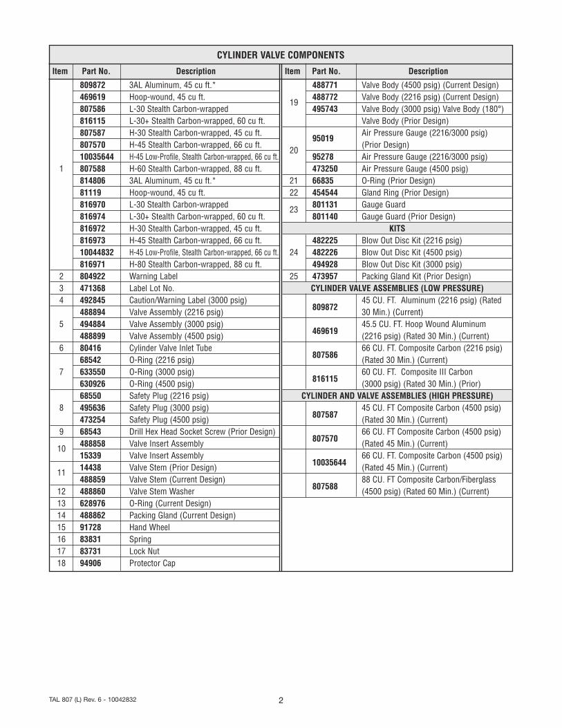
Item Part No. Description
809872 3AL Aluminum, 45 cu ft.*469619 Hoop-wound, 45 cu ft.807586 L-30 Stealth Carbon-wrapped816115 L-30+ Stealth Carbon-wrapped, 60 cu ft.807587 H-30 Stealth Carbon-wrapped, 45 cu ft.807570 H-45 Stealth Carbon-wrapped, 66 cu ft.10035644 H-45 Low-Profile, Stealth Carbon-wrapped, 66 cu ft.
1 807588 H-60 Stealth Carbon-wrapped, 88 cu ft.814806 3AL Aluminum, 45 cu ft.*81119 Hoop-wound, 45 cu ft.816970 L-30 Stealth Carbon-wrapped816974 L-30+ Stealth Carbon-wrapped, 60 cu ft.816972 H-30 Stealth Carbon-wrapped, 45 cu ft.816973 H-45 Stealth Carbon-wrapped, 66 cu ft.10044832 H-45 Low-Profile, Stealth Carbon-wrapped, 66 cu ft.816971 H-80 Stealth Carbon-wrapped, 88 cu ft.
2 804922 Warning Label3 471368 Label Lot No.4 492845 Caution/Warning Label (3000 psig)
488894 Valve Assembly (2216 psig)5 494884 Valve Assembly (3000 psig)
488899 Valve Assembly (4500 psig)6 80416 Cylinder Valve Inlet Tube
68542 O-Ring (2216 psig)7 633550 O-Ring (3000 psig)
630926 O-Ring (4500 psig)68550 Safety Plug (2216 psig)
8 495636 Safety Plug (3000 psig)473254 Safety Plug (4500 psig)
9 68543 Drill Hex Head Socket Screw (Prior Design)
10 488858 Valve Insert Assembly15339 Valve Insert Assembly
11 14438 Valve Stem (Prior Design)488859 Valve Stem (Current Design)
12 488860 Valve Stem Washer13 628976 O-Ring (Current Design)14 488862 Packing Gland (Current Design)15 91728 Hand Wheel16 83831 Spring17 83731 Lock Nut18 94906 Protector Cap
Item Part No. Description
488771 Valve Body (4500 psig) (Current Design)
19488772 Valve Body (2216 psig) (Current Design)495743 Valve Body (3000 psig) Valve Body (180°)
Valve Body (Prior Design)
95019Air Pressure Gauge (2216/3000 psig)
20(Prior Design)
95278 Air Pressure Gauge (2216/3000 psig)473250 Air Pressure Gauge (4500 psig)
21 66835 O-Ring (Prior Design)22 454544 Gland Ring (Prior Design)
23 801131 Gauge Guard801140 Gauge Guard (Prior Design)
KITS482225 Blow Out Disc Kit (2216 psig)
24 482226 Blow Out Disc Kit (4500 psig)494928 Blow Out Disc Kit (3000 psig)
25 473957 Packing Gland Kit (Prior Design)CYLINDER VALVE ASSEMBLIES (LOW PRESSURE)
80987245 CU. FT. Aluminum (2216 psig) (Rated30 Min.) (Current)
46961945.5 CU. FT. Hoop Wound Aluminum(2216 psig) (Rated 30 Min.) (Current)
80758666 CU. FT. Composite Carbon (2216 psig)(Rated 30 Min.) (Current)
81611560 CU. FT. Composite III Carbon(3000 psig) (Rated 30 Min.) (Prior)
CYLINDER AND VALVE ASSEMBLIES (HIGH PRESSURE)
80758745 CU. FT Composite Carbon (4500 psig)(Rated 30 Min.) (Current)
80757066 CU. FT Composite Carbon (4500 psig)(Rated 45 Min.) (Current)
1003564466 CU. FT. Composite Carbon (4500 psig)(Rated 45 Min.) (Current)
80758888 CU. FT Composite Carbon/Fiberglass(4500 psig) (Rated 60 Min.) (Current)
CYLINDER VALVE COMPONENTS

3 TAL 807 (L) Rev. 6 - 10042832
Cylinder Valve
10
8
16
15
251211
17
924
20
22
18
23
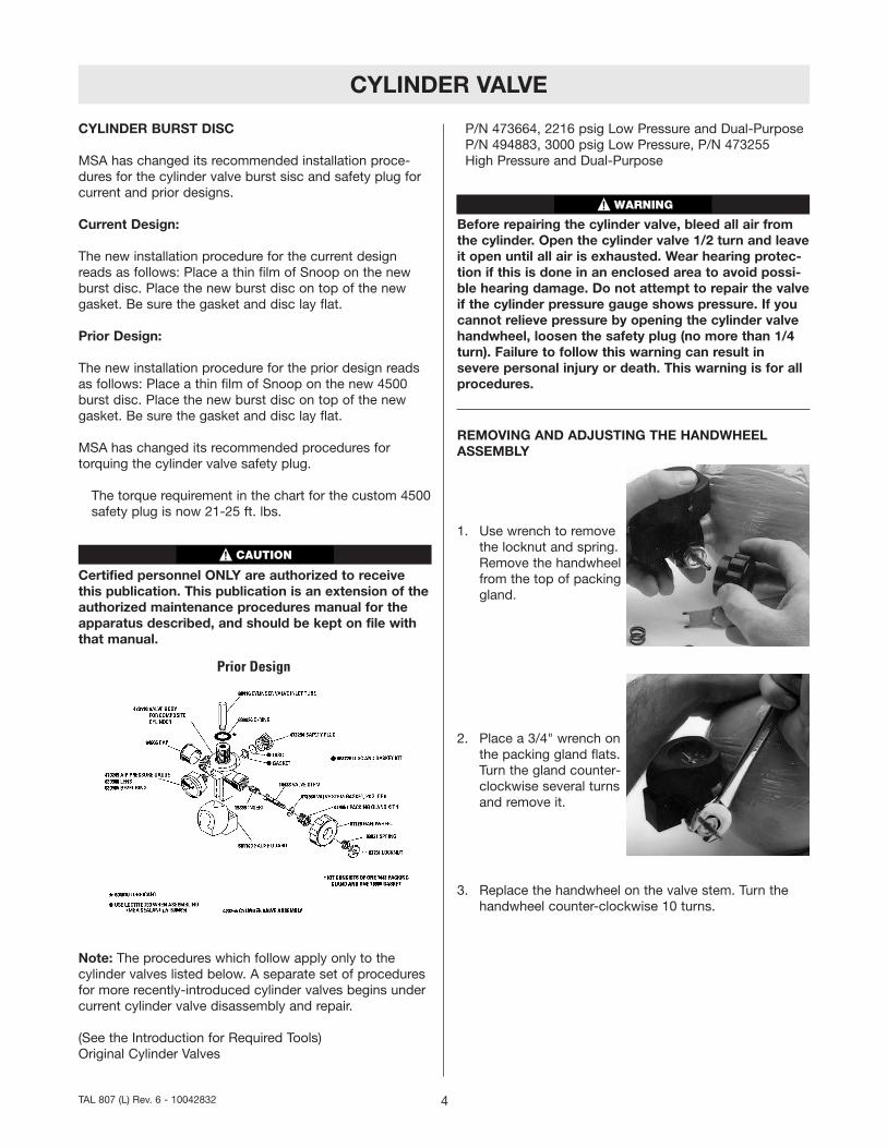
Prior Design
21
65 7
2
1
4
3
5
1413
12
8
17
67
24
18
11
1019
20
23
16
15
Current Design
70 - 75 ft. lbs.
Torque(See page 12)
85 - 105 in. lbs.
Torque(See page 7)
120 - 140 in. lbs.
Snoop
Snoop
CYLINDER VALVE
CYLINDER BURST DISC
MSA has changed its recommended installation proce-dures for the cylinder valve burst sisc and safety plug forcurrent and prior designs.
Current Design:
The new installation procedure for the current designreads as follows: Place a thin film of Snoop on the newburst disc. Place the new burst disc on top of the newgasket. Be sure the gasket and disc lay flat.
Prior Design:
The new installation procedure for the prior design readsas follows: Place a thin film of Snoop on the new 4500burst disc. Place the new burst disc on top of the newgasket. Be sure the gasket and disc lay flat.
MSA has changed its recommended procedures fortorquing the cylinder valve safety plug.
The torque requirement in the chart for the custom 4500safety plug is now 21-25 ft. lbs.
Certified personnel ONLY are authorized to receivethis publication. This publication is an extension of theauthorized maintenance procedures manual for theapparatus described, and should be kept on file withthat manual.
Note: The procedures which follow apply only to thecylinder valves listed below. A separate set of proceduresfor more recently-introduced cylinder valves begins undercurrent cylinder valve disassembly and repair.
(See the Introduction for Required Tools)Original Cylinder Valves
P/N 473664, 2216 psig Low Pressure and Dual-PurposeP/N 494883, 3000 psig Low Pressure, P/N 473255High Pressure and Dual-Purpose
Before repairing the cylinder valve, bleed all air fromthe cylinder. Open the cylinder valve 1/2 turn and leaveit open until all air is exhausted. Wear hearing protec-tion if this is done in an enclosed area to avoid possi-ble hearing damage. Do not attempt to repair the valveif the cylinder pressure gauge shows pressure. If youcannot relieve pressure by opening the cylinder valvehandwheel, loosen the safety plug (no more than 1/4turn). Failure to follow this warning can result insevere personal injury or death. This warning is for allprocedures.
REMOVING AND ADJUSTING THE HANDWHEELASSEMBLY
1. Use wrench to removethe locknut and spring.Remove the handwheelfrom the top of packinggland.
2. Place a 3/4" wrench onthe packing gland flats.Turn the gland counter-clockwise several turnsand remove it.
3. Replace the handwheel on the valve stem. Turn thehandwheel counter-clockwise 10 turns.
4TAL 807 (L) Rev. 6 - 10042832
Prior Design
CAUTION
WARNING
CYLINDER VALVE
4. Turn the valve upside-down and remove thestem, gasket, and nyloninsert.
Note: If the insert shows wear, replace it.
REPLACING THE NYLON INSERT
1. Install a new nyloninsert into the valvebody using the valvestem. Thread the stemfinger-tight (clockwise).
2. Place a new gasket over the valve stem and seat it onthe lip in the valve body.
3. Thread the packing gland into the cylinder valve bodyuntil lit is finger-tight.
4. Finger-loosen the valve stem counter-clockwise untilthe stem stops. Be sure that the packing gland doesnot turn.
5. Use a torque wrenchset at 120 to 140 in.lbs. with a 3/4" socketto tighten the packinggland.
6. Place the handwheel on the stem and check the valvefor proper motion. The handwheel should move freely,but with some resistance. Remove the handwheel.
7. Replace the handwheel and the spring. Be sure thatthe valve is fully open to allow the locknut to beinstalled more easily. The valve stem square must fitinto the square hole in the handwheel.
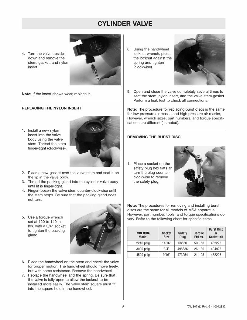
8. Using the handwheellocknut wrench, pressthe locknut against thespring and tighten(clockwise).
9. Open and close the valve completely several times toseat the stem, nylon insert, and the valve stem gasket.Perform a leak test to check all connections.
Note: The procedure for replacing burst discs is the samefor low pressure air masks and high pressure air masks,However, wrench sizes, part numbers, and torque specifi-cations are different (as noted).
REMOVING THE BURST DISC
1. Place a socket on thesafety plug hex flats anturn the plug counter-clockwise to removethe safety plug.
Note: The procedures for removing and installing burstdiscs are the same for all models of MSA apparatus.However, part number, tools, and torque specifications dovary. Refer to the following chart for specific items.
5 TAL 807 (L) Rev. 6 - 10042832
Burst DiscMSA SCBA Socket Safety Torque &Model Size Plug Ft/Lbs. Gasket Kit
2216 psig 11/16” 68550 50 - 53 482225
3000 psig 3/4” 495636 26 - 30 494928
4500 psig 9/16” 473254 21 - 25 482226

CYLINDER VALVE
2. Use a jeweler's screw-driver to punch a holein the burst disc. Useretaining ring pliers topull the disc out of thecylinder valve body.Discard the disc.
3. Use the O-ring removal tool or plastic stick to lift thegasket out of the cylinder valve body.
INSTALLING A NEW BURST DISC FOR 2216 OR 3000PSIG
1. Insert a new gasket into the cylinder valve.
2. Place a thin film ofSnoop on the newburst disc.
3. Place new burst disc on top of the gasket. Be surethat gasket and disc lay flat.
Be sure gasket, then burst disc, are installed in theorder described. Ensure threads of burst disc area andsafety plug threads are free of Christo-Lube. Failure toinstall properly may cause burst disc malfunction, andmay result in serious personal injury or death.
DO NOT re-use the burst disc or the gasket. You maychange the burst rating.
4. Thread the safety plug into the cylinder valve body.
5. Use a torque wrenchwith a socket to tightenthe plug.
This completes the burst disc repair procedures.
CURRENT DESIGN 4500 PSIG
Installing a New 4500 Burst Disc1. Insert a new gasket into the cylinder valve body.
Be sure gasket, then burst disc, are installed in theorder described. Failure to install properly may causeburst disc malfunction, and may result in serious per-sonal injury or death. Do not re-use the burst disc orthe copper gasket.
2. Place a thin film of Snoop on the new 4500 BurstDisc. Place the new burst disc on top of the new gas-ket. Be sure the gasket and disc lay flat.
3. Thread the safety pluginto the cylinder valvebody. Use a torquewrench and socket totighten the plug to thetorque specified.
4. See the leak testing section. This completes the burstdisc repair procedure.
6TAL 807 (L) Rev. 6 - 10042832
CAUTION
WARNING
WARNING

CYLINDER VALVE
CYLINDER VALVE PRESSURE GAUGES
Low pressure and high pressure apparatus use an alu-minum cylinder valve. The low pressure pressure gaugesare secured from inside the valve body 2216 psig: P/N473664; 3000 psig: P/N 494883. To remove the gauge,the cylinder valve must be disassembled. The high pres-sure pressure gauge uses a male thread which is threadedinto the cylinder valve body (P/N 473255). The cylindervalve does not have to be disassembled.
Note: To remove a Low Pressure pressure gauge theburst disc must first be removed.
REMOVING THE CYLINDER VALVE GAUGE
1. Remove the rubbergauge guard. Insert a5/32" allen wrench intothe screw. Turn thewrench counter-clock-wise until the screw iscompletely out of thecylinder valve body.
2. Pull the pressure gaugeout of the cylindervalve body.
3. Use the O-ring removaltool to lift the O-ringand gland ring out ofthe cylinder valve body.Discard the O-ring. Becareful not to scratchthe surface of the cylin-der valve body.
INSTALLING A NEW LOW PRESSURE PRESSUREGAUGE
1. Install a gland ring by pressing it in place using thepressure gauge. DO NOT use a sharp tool or you maydamage the gland ring.
2. Apply a thin film of Christo-Lube to the O-ring, thenplace the O-ring inside the gland ring and press theminto place using the pressure gauge. DO NOT use asharp tool or you may damage the O-ring.
3. Check that the twoindex screws on theback of the pressuregauge are tight. Insertthe pressure gauge intothe cylinder valve bodyso that the gauge nee-dle points to thethreads of the cylindervalve outlet.
4. Use a 5/32" allen wrench to insert the screw from theopposite side of the cylinder valve body. Turn thewrench clockwise to tighten the gauge.
5. Install a new burst disc, a new gasket (Burst Disc andGasket Kit), and the safety plug.
DO NOT re-use the burst disc or the copper gasket.You may change the burst rating.
REMOVING THE HIGH PRESSURE PRESSURE GAUGE
1. Remove the rubber gauge protector. Unscrew andremove bezel ring and lens. Store the lens in a safeplace.
2. Position the cylindervalve so that the gaugeis upside-down. If theplastic center-post fallsout of the gauge, applya thin film of Christo-Lube to the part andre-install it. Place thegauge wrench on thegauge flats. Turn thegauge counter-clock-wise and remove it from the cylinder valve body.
3. Clean out the threads in the cylinder valve body to besure no tape residue remains.
7 TAL 807 (L) Rev. 6 - 10042832
CAUTION
CYLINDER VALVE
REASSEMBLING OR INSTALLING A NEW HIGH PRES-SURE PRESSURE GAUGE (P/N 473249)
1. Apply pipe-sealing tape to gauge threads. (See Note#3).
2. Place the gauge wrench on the gauge flats. Turn thegauge clockwise to tighten. Do not over-tighten.
3. Position the gauge so that the gauge needle points tothe threads of the cylinder valve outlet.
4. Replace the lens in the bezel ring and tighten the ring.5. Replace the rubber gauge protector.6. Refer to Leak-Testing and check all connections.This completes the pressure gauge replacement proce-dure.
REMOVING THE CYLINDER VALVE BODY FROM THECYLINDER
Bleed all air from the cylinder. Open the cylinder valvehandwheel 1/2 turn and leave it open until all air isexhausted. Wear hearing protection if this is done inan enclosed area to avoid possible hearing damage.Do not remove the valve if the cylinder pressure gaugeshows pressure. If you cannot relieve pressure byopening the cylinder valve handwheel, loosen thesafety plug (no more than 1/4 turn). Failure to followthis precaution may result in severe personal injury ordeath.
1. Secure the cylinder in a suitable fixture.2. Pull off the rubber pressure gauge guard.
3. Place a 7/8" socket (12point) or wrench on theflats on the top of thecylinder valve. Turn thesocket counter-clock-wise until the cylindervalve is completely outof the cylinder.
4. To remove the O-ring(P/N 68542 for 2216psig valves; P/N633550 for 3000 psigvalves; P/N 630926 for4500 psig valves), rollthe O-ring over thethreads.
5. If the cylinder valve inlet tube is damaged, the entirecylinder valve must be replaced. The inlet tube is"locked" with a non-removable thread sealant.
INSTALLING THE CYLINDER VALVE BODY IN THECYLINDER
(Low Pressure 2216 psig: P/N 473664 valve body; LowPressure 3000 psig: P/N 494883 valve body; HighPressure; P/N 473255 valve body)
1. Secure the cylinder in a suitable fixture.2. Use a high intensity light. Inspect the inside of the
cylinder for contaminants. Remove any loose parti-cles. Be sure that the cylinder interior is completelydry.
DO NOT use the cylinder if it has an odor or is conta-minated internally. Failure to follow this precautionmay result in severe personal injury or death.
3. Clean the O-ring sealing surface on the cylinder with aclean, dry, lint-free cloth. Be sure this cylinder surfaceis undamaged and free from contaminants, such asdirt or tape residue.
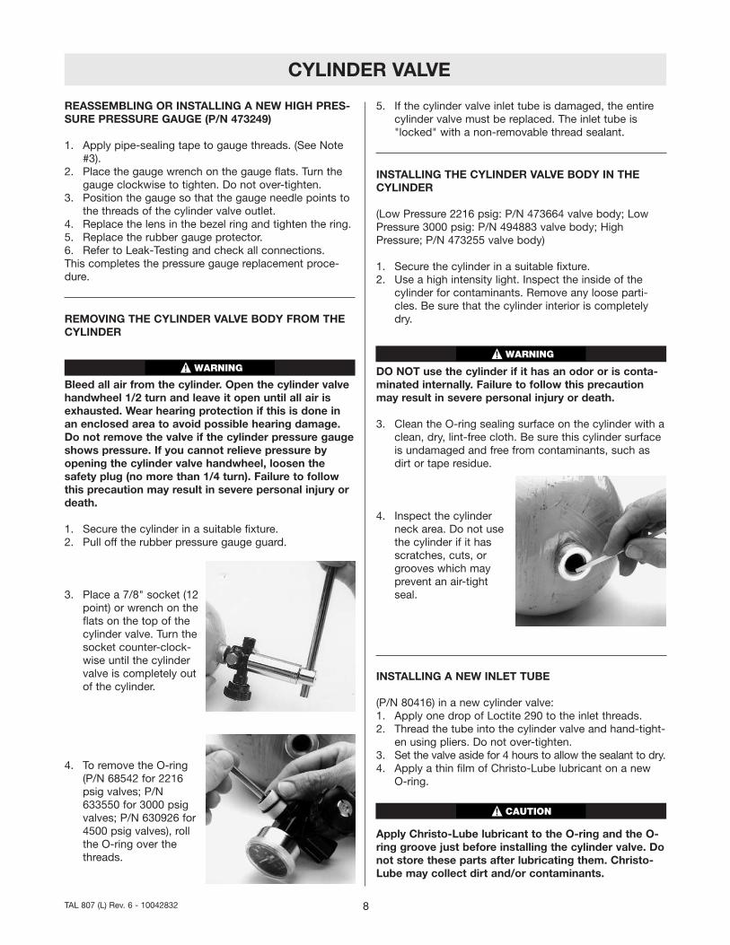
4. Inspect the cylinderneck area. Do not usethe cylinder if it hasscratches, cuts, orgrooves which mayprevent an air-tightseal.
INSTALLING A NEW INLET TUBE
(P/N 80416) in a new cylinder valve:1. Apply one drop of Loctite 290 to the inlet threads.2. Thread the tube into the cylinder valve and hand-tight-
en using pliers. Do not over-tighten.3. Set the valve aside for 4 hours to allow the sealant to dry.4. Apply a thin film of Christo-Lube lubricant on a new
O-ring.
Apply Christo-Lube lubricant to the O-ring and the O-ring groove just before installing the cylinder valve. Donot store these parts after lubricating them. Christo-Lube may collect dirt and/or contaminants.
8TAL 807 (L) Rev. 6 - 10042832
WARNINGWARNING
CAUTION
CYLINDER VALVE
5. Apply two 1/16" diameter drops of Christo-Lube in theO-ring groove at locations 180 degrees apart.
6. Place a plastic threadprotector or thin pieceof paper over thethreads, then roll theO-ring to the bottom(male thread) end ofthe valve body. Rotatethe O-ring 1/2 to 3/4turn to work theChristo-Lube evenlyaround the groove.Remove the threadprotector.
7. Insert the cylinder valveinto the cylinder neckslowly and carefully sothat the sealing surfaceof the cylinder is notdamaged by the tubeor sharp edge of thevalve threads.
8. Use a torque wrench with a 13/16" socket to tightenthe cylinder valve according to the following table:
9. Refer to Leak-Testing and check all connections.
This completes the original cylinder valve replacementprocedure.
9 TAL 807 (L) Rev. 6 - 10042832
P/N ITEM REQUIRED
473255 Al. Cylinder Valve for High 70-75Pressure (gray, 4500 psig) ft. pounds
473664 Al. Cylinder Valve for Low 70-75Pressure (black, 2216 psig) ft. pounds
494883 Al. Cylinder Valve for Low 70-75Pressure (3000 psig) ft. pounds
93998 Brass Cyl. Valve for 2216 psig 90-100Steel Cyl., bright (silver) plated ft. pounds
460321 Brass Cylinder Valve for 45-50Composite Cyl., 2216 psig, ft. poundsdull, silver, cadmium plated
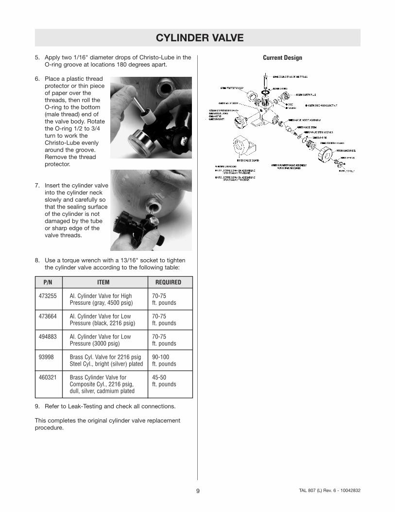
Current Design
CYLINDER VALVE
CURRENT CYLINDER VALVE DISASSEMBLY ANDREPAIR
Before repairing the cylinder valve, all air must be bledfrom the cylinder. Open the cylinder valve handwheel1/2 turn and leave it open until all air has beenexhausted. Wear hearing protection if this is done inan enclosed area to avoid possible hearing damage.Do not attempt to repair the valve is pressure isshown on the cylinder pressure gauge. If pressurecannot be relieved by opening the cylinder valve hand-wheel, loosen the safety plug (no more than _ turn).Failure to follow this precaution may result in seriouspersonal injury or death.
REMOVING THE PRESSURE GAUGE
1. Remove the rubber gauge protector. Unscrew andremove bezel ring and lens. Store the lens in a safeplace.
2. Position the cylinder valve so that the gauge isupside-down. If the plastic center-post falls out of thegauge, apply a thin film of Christo-Lube to the partand re-install it. Place the gauge wrench on the gaugeflats. Turn the gauge counter-clockwise and remove itfrom the cylinder valve body.
3. Clean out the threads in the cylinder valve body to besure no tape residue remains.
REASSEMBLING OR INSTALLING A NEW PRESSUREGAUGE
1. Apply pipe-sealing tape to gauge threads. (See Note#3).
2. Place the gauge wrench on the gauge flats. Turn thegauge clockwise to tighten. Do not over-tighten.
3. Position the gauge so that the gauge needle points tothe threads of the cylinder valve outlet.
4. Replace the lens in the bezel ring and tighten the ring.5. Replace the rubber gauge protector.6. Refer to Leak-Testing and check all connections. This
completes the pressure gauge replacement procedure.
REMOVING THE HANDWHEEL
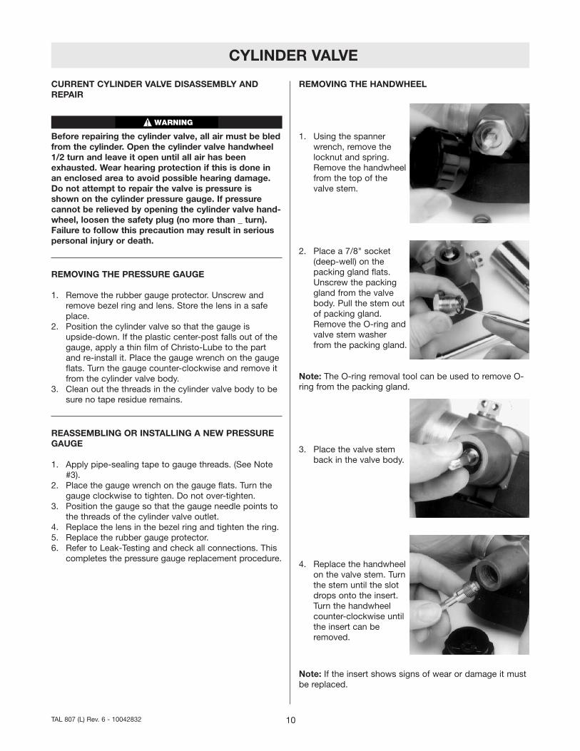
1. Using the spannerwrench, remove thelocknut and spring.Remove the handwheelfrom the top of thevalve stem.
2. Place a 7/8" socket(deep-well) on thepacking gland flats.Unscrew the packinggland from the valvebody. Pull the stem outof packing gland.Remove the O-ring andvalve stem washerfrom the packing gland.
Note: The O-ring removal tool can be used to remove O-ring from the packing gland.
3. Place the valve stemback in the valve body.
4. Replace the handwheelon the valve stem. Turnthe stem until the slotdrops onto the insert.Turn the handwheelcounter-clockwise untilthe insert can beremoved.
Note: If the insert shows signs of wear or damage it mustbe replaced.
10TAL 807 (L) Rev. 6 - 10042832
WARNING
CYLINDER VALVE
INSTALLING THE INSERT
1. Using the valve stem,install the insert in thevalve body. Thread thestem clockwise until theinsert is fingertight.
2. Place a thin film of Christo-Lube lubricant on a newO-ring. Place the O-ring on the packing gland.
3. Place a new washerinto the packing gland.Press the washer downto its seat.
4. Insert the stem into thevalve body. Turn thestem until the slotdrops on the insert.Thread the packinggland into the cylindervalve until it is finger-tight.
5. Turn the valve stem counter-clockwise until the stemstops. Be sure the gland does not turn.
6. Using the inch-pound torque wrench with a 7/8" sock-et (deep-well), tighten the packing gland to 85-105 in.lbs.
7. The valve stem square must fit into the square hole inthe handwheel. Place the handwheel on the stem andcheck the valve for proper motion. The handwheelshould move freely.
8. Replace the spring. Be sure that the valve is fully opento allow the locknut to be installed more easily.
9. Put 1 drop of Loctite #222 on the stem threads.
10. Using the locknutspanner wrench, pressthe locknut against thespring and tightenclockwise until it isflush with the top ofthe handwheel.
11. Open and close the valve completely several times toseat the stem, insert, and the valve stem gasket.
12. Leak-test the valve.
REMOVING THE BURST DISC
Note: The procedures for removing and installing burstdiscs are the same for all models of MSA apparatus.However, part number, tools, and torque specifications dovary. Refer to the following chart for specific items.
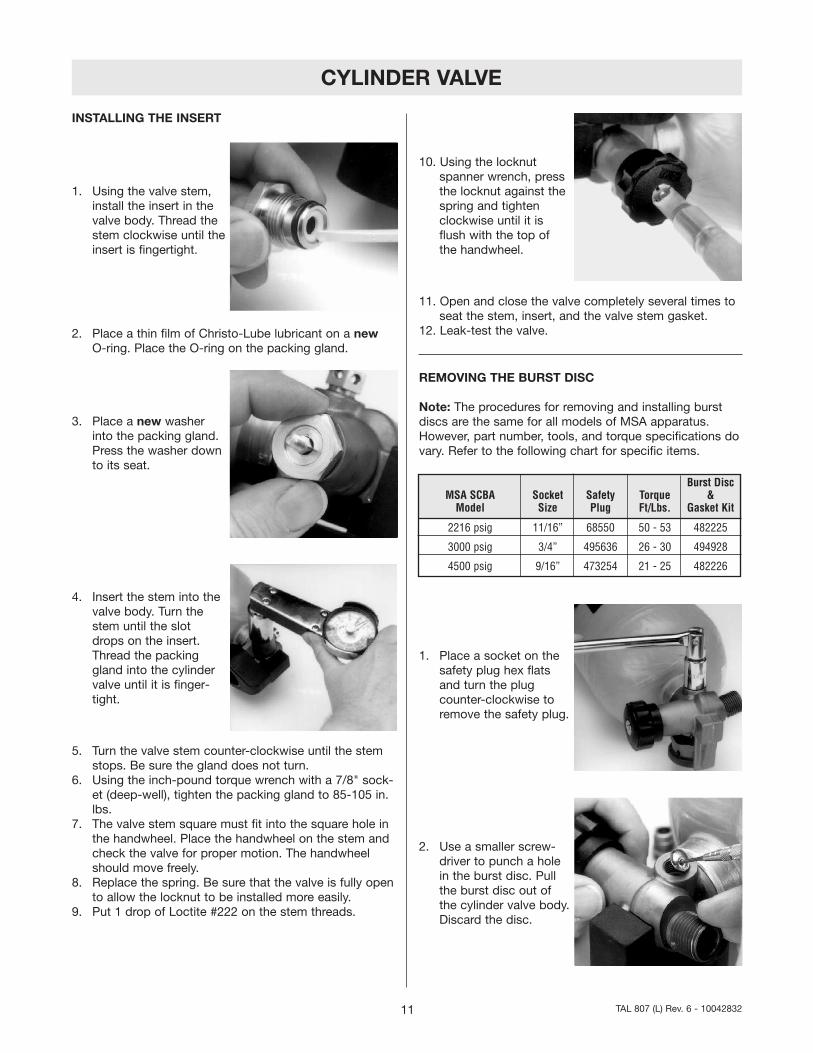
1. Place a socket on thesafety plug hex flatsand turn the plugcounter-clockwise toremove the safety plug.
2. Use a smaller screw-driver to punch a holein the burst disc. Pullthe burst disc out ofthe cylinder valve body.Discard the disc.
11 TAL 807 (L) Rev. 6 - 10042832
Burst DiscMSA SCBA Socket Safety Torque &
Model Size Plug Ft/Lbs. Gasket Kit
2216 psig 11/16” 68550 50 - 53 482225
3000 psig 3/4” 495636 26 - 30 494928
4500 psig 9/16” 473254 21 - 25 482226

CYLINDER VALVE
3. Use the O-ring removaltool or small flat bladescrewdriver to lift thegasket out of the cylin-der valve body. Becareful not to scratchthe surface of thecylinder valve body.
INSTALLING A NEW BURST DISC FOR 2216 OR 3000PSIG
1. Insert a new gasket into the cylinder valve body.2. Place a thin film of Snoop on the new burst disc.
Place the new burst disc on top of the gasket. Be surethe gasket and disc lay flat.
Be sure gasket, then burst disc, are installed in theorder described. Ensure threads of burst disc area andsafety plug threads are free of Christo-Lube. Failure toinstall properly may cause burst disc malfunction, andmay result in serious personal injury or death.
Do not reuse the burst disc or the gasket.
3. Thread the safety pluginto the cylinder valvebody. Use a torquewrench and socket totighten the plug to thetorque in chart.
4. Leak-test the assembly. This completes the burst discrepair procedure.
CURRENT DESIGN 4500 PSIG
Installing a New 4500 Burst Disc1. Insert a new gasket into the cylinder valve body.
Be sure gasket, then burst disc, are installed in theorder described. Failure to install properly may causeburst disc malfunction, and may result in serious per-sonal injury or death.
Do not re-use the burst disc or the copper gasket.
2. Place a thin film of Snoop on the new 4500 BurstDisc. Place the new Burst Disc on top of the new gas-ket. Be sure the gasket and disc lay flat.
3. Thread the safety pluginto the cylinder valvebody. Use a torquewrench and socket totighten the plug to thetorque in chart.
4. See Leak-testing. This completes the burst disc repairprocedure.
REPLACING THE CYLINDER VALVE BODY
1. To remove the cylinder valve body from the cylinder:a. Secure the cylinder in a suitable fixture.b. Remove the rubber pressure gauge guard.
c. Place a 13/16"crowsfoot wrench onthe flats on the endof the cylinder valve.Turn the valvecounter-clockwiseuntil the cylindervalve is completelyout of the cylinder.
12TAL 807 (L) Rev. 6 - 10042832
CAUTION
WARNING
CAUTION
WARNING

CYLINDER VALVE
d.Roll the O-ring (P/N68542 for 2216 psigvalves; P/N 633550for 3000 psig valves;or P/N 630926 for4500 psig valves)over the threads.
e. If the cylinder valve inlet tube is damaged it must beremoved using a wrench or pliers.
INSTALLING A NEW INLET TUBE
1. Turn the cylinder valve upside down.2. Place one drop of Loctite 290 on the inlet tube
threads.3. Finger-tighten the inlet tube into the valve body.
4. Allow the sealant tocure for 4 hours.
INSPECTING INSIDE OF CYLINDER
1. Use a high intensity light to inspect the inside of thecylinder for contamination. Be sure the cylinder interioris completely dry.
Do not use the cylinder if it has an odor, is contami-nated internally, or has any visible signs of damage.Remove from service.
INSTALLING CYLINDER VALVE
1. Clean the O-ring sealing surface on the cylinder with aclean, dry, lint-free cloth. Be sure the cylinder sealingsurface is undamaged and free from contaminants,such as dirt or tape residue.
2. Inspect the cylinder neck area. Do not use the cylinderif it has scratches, cuts, or grooves which may preventan air-tight seal.
3. Install a new O-ring on the cylinder valve following thesteps below:
Apply Christo-Lube lubricant to the O-ring and the O-ring groove just before installing the cylinder valve. Donot store these parts after lubricating them. Christo-Lube may collect dirt and/or contaminants.
a. Place a thin film of Christo-Lube lubricant on thenew O-ring.
b. Place two small diameter drops of Christo-Lubeinto the O-ring groove at locations 180 degreesapart.
c. Place a plasticthread protector orthin piece of paperover the threads,then roll the O-ringto the bottom (malethread) end of thevalve body. Removethe thread protector.
4. Carefully insert the cylinder valve into the cylinderneck so that the sealing surface of the cylinder is notdamaged by the tube or sharp edges of the valvethreads.
5. Use the foot-pound torque wrench with a 13/16"crowsfoot wrench to tighten the cylinder valve to 70-75 ft. lbs.
6. Leak-test the assembly. This completes the cylinderreplacement procedure.
13 TAL 807 (L) Rev. 6 - 10042832
CAUTION
CAUTION