ms8607-02ba01 pht combination sensor · ms8607-02ba01 pht combination sensor sensor solutions...
TRANSCRIPT

SENSOR SOLUTIONS ///MS8607-02BA01 Page 1 09/2015
MS8607-02BA01
PHT Combination Sensor
SPECIFICATIONS
Integrated pressure, humidity and temperature sensor QFN package 5 x 3 x 1 mm3 Operating range: 10 to 2000 mbar, 0%RH to 100%RH, -40 to 85 °C High-resolution module: 0.016 mbar, 0.04%RH, 0.01°C Supply voltage: 1.5 to 3.6 V Fully factory calibrated sensor I2C interface
The MS8607 is the novel digital combination sensor of MEAS providing 3 environmental physical measurements all-in-one: pressure, humidity and temperature (PHT). This product is optimal for applications in which key requirements such as ultra low power consumption, high PHT accuracy and compactness are critical. High pressure resolution combined with high PHT linearity makes the MS8607 an ideal candidate for environmental monitoring and altimeter in smart phones and tablet PC, as well as PHT applications such as HVAC and weather stations. This new sensor module generation is based on leading MEMS technologies and latest benefits from Measurement Specialties proven experience and know-how in high volume manufacturing of sensor modules, which has been widely used for over a decade.
MS8607-02BA01
PHT Combination Sensor
SENSOR SOLUTIONS ///MS8607-02BA01 09/2015 Page 2
FEATURES
FIELD OF APPLICATION
Smart phones and Tablet PCs HVAC applications Weather station Printers Home Appliance and humidifiers
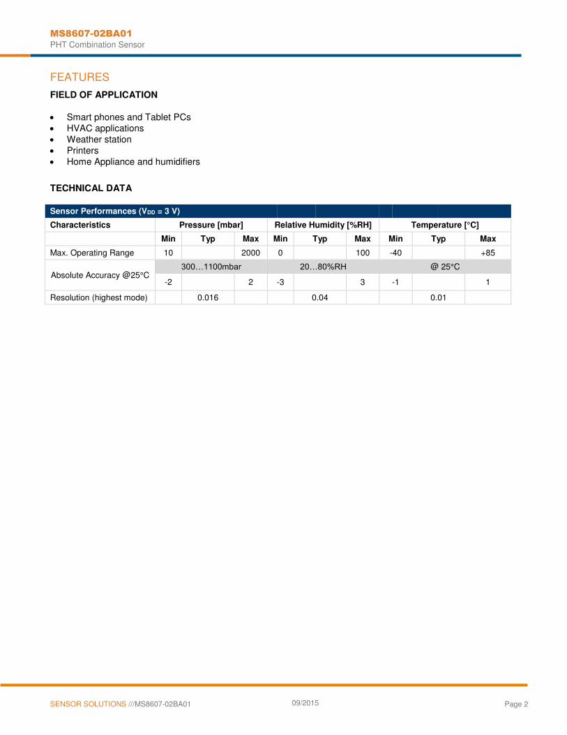
TECHNICAL DATA
Sensor Performances (VDD = 3 V)
Characteristics Pressure [mbar] Relative Humidity [%RH] Temperature [°C]
Min Typ Max Min Typ Max Min Typ Max
Max. Operating Range 10 2000 0 100 -40 +85
Absolute Accuracy @25°C 300…1100mbar 20…80%RH @ 25°C
-2 2 -3 3 -1 1
Resolution (highest mode) 0.016 0.04 0.01
MS8607-02BA01
PHT Combination Sensor
SENSOR SOLUTIONS ///MS8607-02BA01 09/2015 Page 3
PERFORMANCE SPECIFICATIONS
ABSOLUTE MAXIMUM RATINGS
Parameter Symbol Condition Min. Typ. Max. Unit
Supply voltage VDD -0.3 3.6 V
Storage temperature TS -20 85 °C
Overpressure Pmax 6 bar
Maximum Soldering Temperature
Tmax 40 sec max
250 °C
ESD rating Human Body Model -2 2 kV
Latch up JEDEC standard No 78 -100 100 mA
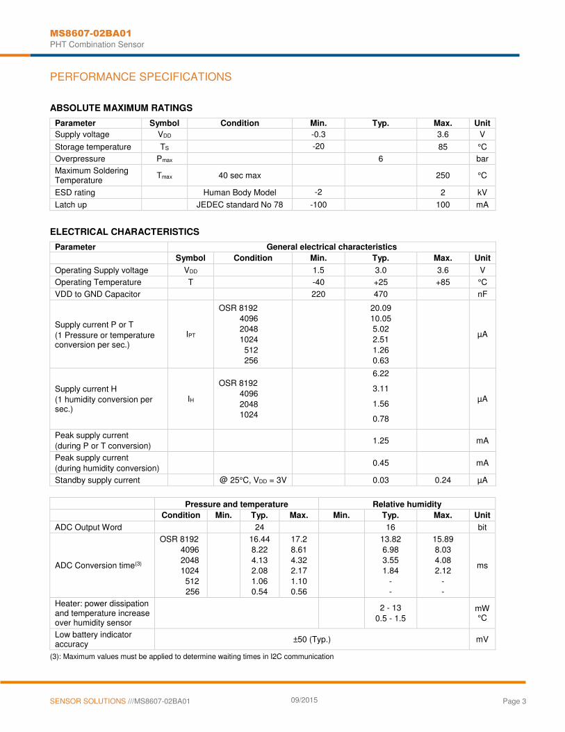
ELECTRICAL CHARACTERISTICS
Parameter General electrical characteristics
Symbol Condition Min. Typ. Max. Unit
Operating Supply voltage VDD 1.5 3.0 3.6 V
Operating Temperature T -40 +25 +85 °C
VDD to GND Capacitor 220 470 nF
Supply current P or T
(1 Pressure or temperature conversion per sec.)
IPT
OSR 8192
4096 2048
1024
512 256
20.09
10.05 5.02
2.51
1.26 0.63
µA
Supply current H
(1 humidity conversion per sec.)
IH
OSR 8192
4096
2048 1024
6.22
3.11
1.56
0.78
µA
Peak supply current
(during P or T conversion)
1.25 mA
Peak supply current
(during humidity conversion)
0.45 mA
Standby supply current @ 25°C, VDD = 3V 0.03 0.24 µA
Pressure and temperature Relative humidity
Condition Min. Typ. Max. Min. Typ. Max. Unit
ADC Output Word 24 16 bit
ADC Conversion time(3)
OSR 8192
4096
2048 1024
512 256
16.44
8.22
4.13 2.08
1.06 0.54
17.2
8.61
4.32 2.17
1.10 0.56
13.82
6.98
3.55 1.84
- -
15.89
8.03
4.08 2.12
- -
ms
Heater: power dissipation and temperature increase over humidity sensor
2 - 13
0.5 - 1.5
mW °C
Low battery indicator accuracy
±50 (Typ.) mV
(3): Maximum values must be applied to determine waiting times in I2C communication

MS8607-02BA01
PHT Combination Sensor
SENSOR SOLUTIONS ///MS8607-02BA01 09/2015 Page 4
PERFORMANCE SPECIFICATIONS (CONTINUED)
PHT CHARACTERISTICS (VDD = 3.0 V, T = 25 °C UNLESS OTHERWISE NOTED)
Pressure [mbar] Relative Humidity [%RH] Temperature [°C]
Min. Typ. Max. Min. Typ. Max. Min. Typ. Max.
Operating Range Extended Range (4)
300
10
1200
2000 0 100 -40 85
Absolute Accuracy @25°C
300…1100 mbar 20 …80%RH @25°C
-2 2 -3 3 -1 1
Absolute Accuracy 300…1100mbar, -20...85°C 5…95%RH -20...85°C
-4 4 -5 5 -2 2
Relative Accuracy
@25°C
700…1000 mbar (5)
±0.1 (6)
Resolution RMS(7)
OSR 8192
4096
2048 1024
512 256
0.016
0.021
0.028 0.039
0.062 0.11
0.04 -
-
0.7
0.002
0.003
0.004 0.006
0.009 0.012
Maximum error with supply voltage (Condition)
±0.5 ±0.25 ±0.3
(VDD = 1.5 V … 3.6 V) Long-term stability ±1 / year ±0.5 / year ±0.3 / year
Reflow soldering impact -0.6 2
Recovering time after reflow (8)
5 days 5 days
Response Time
(Condition)
< 5ms 5 sec.
(at 63% of signal recovery,
From 33%RH to 75%RH, At 3m/s air flow)
(4): Linear range of ADC
(5): Auto-zero at one pressure point
(6): Characterized value performed on qualification devices
(7): Characterization performed sequentially (P&T conversion followed by H conversion)
(8): Recovering time at least 66% of the reflow impact
DIGITAL INPUTS (SDA, SCL)
Parameter Symbol Conditions Min. Typ. Max. Unit
Serial data clock SCL 400 kHz
Input high voltage VIH 80% VDD 100% VDD V
Input low voltage VIL 0% VDD 20% VDD V
DIGITAL OUTPUTS (SDA)
Parameter Symbol Conditions Min. Typ. Max. Unit
Output high voltage VOH Isource = 1 mA 80% VDD 100% VDD V
Output low voltage VOL Isink = 1 mA 0% VDD 20% VDD V
Load Capacitance CLOAD 16 pF

MS8607-02BA01
PHT Combination Sensor
SENSOR SOLUTIONS ///MS8607-02BA01 09/2015 Page 5
PERFORMANCE CHARACTERISTICS
PHT ACCURACY AND PHT ERROR VERSUS SUPPLY VOLTAGE (TYPICAL)

MS8607-02BA01
PHT Combination Sensor
SENSOR SOLUTIONS ///MS8607-02BA01 09/2015 Page 6
FUNCTIONAL DESCRIPTION
GENERAL
The MS8607 includes two sensors with distinctive MEMS technologies to measure pressure, humidity and temperature. The first sensor is a piezo-resistive sensor providing pressure and temperature. The second sensor is a capacitive type humidity sensor providing relative humidity. Each sensor is interfaced to a ΔΣ ADC integrated circuit for the digital conversion. The MS8607 converts both analog output voltages to a 24-bit digital value for the pressure and temperature measurements, and a 12-bit digital value for the relative humidity measurement.
SERIAL I2C INTERFACE
The external microcontroller clocks in the data through the input SCL (Serial CLock) and SDA (Serial DAta). Both sensors respond on the same pin SDA which is bidirectional for the I2C bus interface. Two distinct I2C addresses are used (one for pressure and temperature, the other for relative humidity, see Figure 2).
Module reference Mode Pins used
MS860702BA01 I2C SDA, SCL
Figure 1: Communication Protocol and pins
Sensor type I2C address (binary value) I2C address (hex. value)
Pressure and Temperature P&T 1110110 0x76 Relative Humidity RH 1000000 0x40
Figure 2: I2C addresses
COMMANDS FOR PRESSURE AND TEMPERATURE
For pressure and temperature sensing, five commands are possible: 1. Reset 2. Read PROM P&T (112 bit of calibration words) 3. D1 conversion 4. D2 conversion 5. Read ADC (24 bit pressure / temperature)
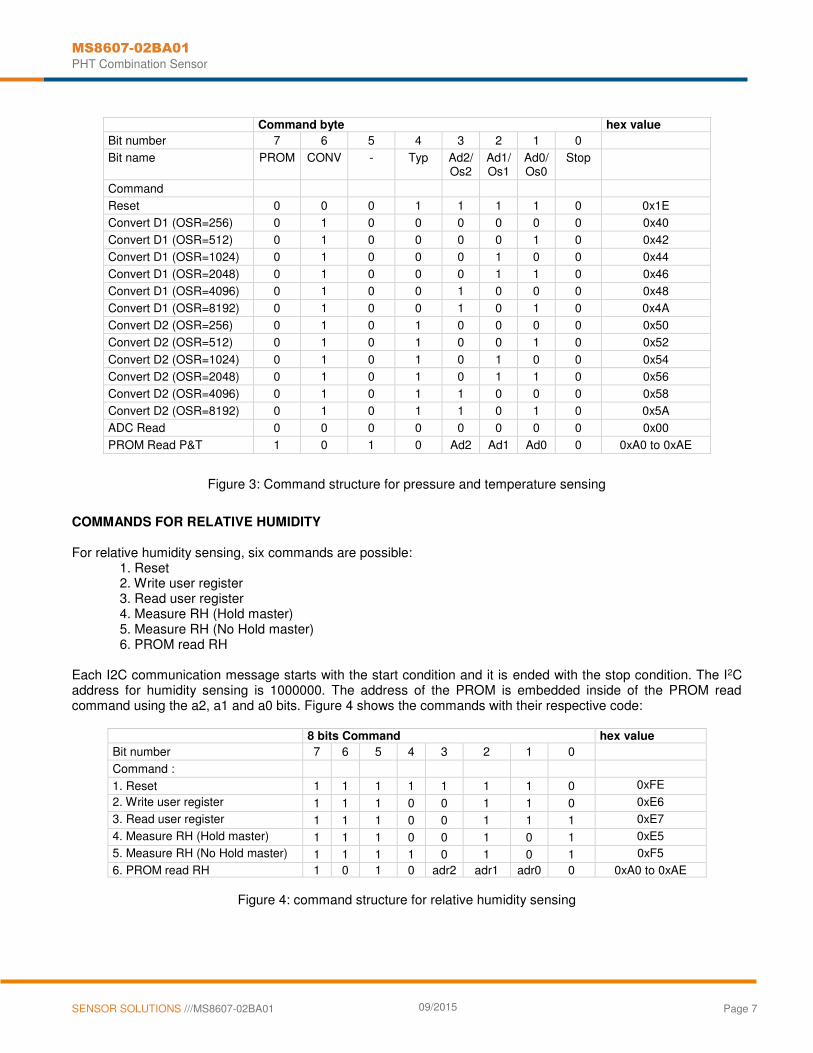
Each command is represented over 1 byte (8 bits) as described in Figure 3. After ADC read commands, the device will return 24 bit result and after the PROM read 16 bit results. The address of the PROM is embedded inside of the read PROM P&T command using the a2, a1 and a0 bits.
MS8607-02BA01
PHT Combination Sensor
SENSOR SOLUTIONS ///MS8607-02BA01 09/2015 Page 7
Command byte hex value
Bit number 7 6 5 4 3 2 1 0
Bit name PROM CONV - Typ Ad2/Os2
Ad1/Os1
Ad0/Os0
Stop
Command
Reset 0 0 0 1 1 1 1 0 0x1E
Convert D1 (OSR=256) 0 1 0 0 0 0 0 0 0x40
Convert D1 (OSR=512) 0 1 0 0 0 0 1 0 0x42
Convert D1 (OSR=1024) 0 1 0 0 0 1 0 0 0x44
Convert D1 (OSR=2048) 0 1 0 0 0 1 1 0 0x46
Convert D1 (OSR=4096) 0 1 0 0 1 0 0 0 0x48
Convert D1 (OSR=8192) 0 1 0 0 1 0 1 0 0x4A
Convert D2 (OSR=256) 0 1 0 1 0 0 0 0 0x50
Convert D2 (OSR=512) 0 1 0 1 0 0 1 0 0x52
Convert D2 (OSR=1024) 0 1 0 1 0 1 0 0 0x54
Convert D2 (OSR=2048) 0 1 0 1 0 1 1 0 0x56
Convert D2 (OSR=4096) 0 1 0 1 1 0 0 0 0x58
Convert D2 (OSR=8192) 0 1 0 1 1 0 1 0 0x5A
ADC Read 0 0 0 0 0 0 0 0 0x00
PROM Read P&T 1 0 1 0 Ad2 Ad1 Ad0 0 0xA0 to 0xAE
Figure 3: Command structure for pressure and temperature sensing
COMMANDS FOR RELATIVE HUMIDITY For relative humidity sensing, six commands are possible:
1. Reset 2. Write user register 3. Read user register 4. Measure RH (Hold master) 5. Measure RH (No Hold master) 6. PROM read RH
Each I2C communication message starts with the start condition and it is ended with the stop condition. The I2C address for humidity sensing is 1000000. The address of the PROM is embedded inside of the PROM read command using the a2, a1 and a0 bits. Figure 4 shows the commands with their respective code:
8 bits Command hex value
Bit number 7 6 5 4 3 2 1 0
Command :
1. Reset 1 1 1 1 1 1 1 0 0xFE
2. Write user register 1 1 1 0 0 1 1 0 0xE6
3. Read user register 1 1 1 0 0 1 1 1 0xE7
4. Measure RH (Hold master) 1 1 1 0 0 1 0 1 0xE5
5. Measure RH (No Hold master) 1 1 1 1 0 1 0 1 0xF5
6. PROM read RH 1 0 1 0 adr2 adr1 adr0 0 0xA0 to 0xAE
Figure 4: command structure for relative humidity sensing

MS8607-02BA01
PHT Combination Sensor
SENSOR SOLUTIONS ///MS8607-02BA01 09/2015 Page 8
USER REGISTER
The user register is used to configure several operating modes of the humidity sensor (resolution measurements, heater) and monitor the battery state. The possible configurations of the user register are described in the table below. User register Bit Bit Configuration/Coding Default value bit 7, bit 0
Measurement resolution
Bit 7 Bit 0 OSR Resolution 0 0 4096 Highest 0 1 2048 1 0 1024 1 1 256 Lowest
‘00’
bit 6 Battery state: ‘0’ VDD>2.25V ‘1’ VDD<2.25V
‘0’
bit 3,4,5 Reserved ‘000’ bit 2 on-chip heater:
‘0’ heater disabled ‘1’ heater enabled
‘0’
bit 1 Reserved ‘0’
Figure 5: description of the user register
Bit 7 and bit 0 configure the measurement resolution (highest resolution OSR 4096, lowest OSR 256). Bit 6 refers to the “Battery state”, which can be monitored. Bits 1,3,4,5 are reserved bits, which must not be changed and default values of respective reserved bits may change over time without prior notice. Therefore, for any writing to user register, default values of reserved bits must be read first. Bit 2 configures the heater. It can be used for functionality diagnosis: relative humidity drops upon rising temperature. The heater consumes about 5.5mW and provides a temperature increase of approximatively 0.5-1.5°C over the humidity sensor.

MS8607-02BA01
PHT Combination Sensor
SENSOR SOLUTIONS ///MS8607-02BA01 09/2015 Page 9
PRESSURE AND TEMPERATURE CALCULATION
Figure 6: Flow chart for pressure and temperature reading and software compensation.
Size [1]
[bit] min
C1 Pressure sensitivity | SENS T1 unsigned int 16 16 0 65535 46372
C2 Pressure offset | OFF T1 unsigned int 16 16 0 65535 43981
C3 Temperature coefficient of pressure sensitivity | TCS unsigned int 16 16 0 65535 29059
C4 Temperature coefficient of pressure offset | TCO unsigned int 16 16 0 65535 27842
C5 Reference temperature | T REF unsigned int 16 16 0 65535 31553
C6 Temperature coefficient of the temperature | TEMPSENS unsigned int 16 16 0 65535 28165
D1 Digital pressure value unsigned int 32 24 0 16777215 6465444
D2 Digital temperature value unsigned int 32 24 0 16777215 8077636
dT Difference between actual and reference temperature [2]
dT = D2 - T REF = D2 - C5 * 2 8 signed int 32 25 -16776960 16777215 68
2000
= 20.00 °C
OFF Offset at actual temperature [3]
OFF =
OFF T1
+
TCO
*
dT =
C2
*
2 17
+
(C4
*
dT )
/
2 6
signed int 64 41 -17179344900 25769410560 5764707214
SENS Sensitivity at actual temperature [4]
SENS =
SENS T1
+
TCS
*
dT
=
C1 * 2 16
+
( C3
*
dT )
/
2 7
signed int 64 41 -8589672450 12884705280 3039050829
110002
= 1100.02 mbar
Notes [1] [2] [3] [4]
min and max have to be defined min and max have to be defined
Maximal size of intermediate result during evaluation of variable
120000 1000 58
P
Recommended variable type Description | Equation
signed int 32 Actual temperature (-40…85°C with 0.01°C resolution) TEMP
=
20°C
+
dT
*
TEMPSENS
=
2000
+
dT
*
C6
/
2 23
Read digital pressure and temperature data
signed int 32 Temperature compensated pressure (10…1200mbar with 0.01mbar resolution) P = D1 * SENS - OFF = (D1 * SENS / 2 21
- OFF) / 2 15
min and max have to be defined
Convert calibration data into coefficients (see bit pattern of W1 to W4)
Variable Example /
Typical Value
Calculate temperature compensated pressure
8500 -4000 TEMP 41
Start Maximum values for calculation results:
P MIN = 10mbar P MAX = 2000mbar T MIN = -40°C T MAX = 85°C T REF = 20°C
Read calibration data (factory calibrated) from PROM
Read digital pressure and temperature data
Calculate temperature
Calculate temperature compensated pressure
Pressure and temperature value first order
max

MS8607-02BA01
PHT Combination Sensor
SENSOR SOLUTIONS ///MS8607-02BA01 09/2015 Page 10
PRESSURE COMPENSATION (SECOND ORDER OVER TEMPERATURE)
In order to optimize the accuracy over temperature range at low temperature, it is recommended to compensate the pressure non-linearity over the temperature. This can be achieved by correcting the calculated temperature, offset and sensitivity by a second-order correction factor. The second-order factors are calculated as follows:
Figure 7: Flow chart for pressure and temperature to the optimum accuracy.
Yes No
SENS2 = 29 (TEMP – 2000)2/ 24 SENS2 = 0
SENS = SENS - SENS2
TEMP<20°C
Low temperature
T2 = 3 dT 2 / 2
33
OFF2 = 0 T2 = T2 = 5 dT / 2
2 38
OFF2 = 61 (TEMP – 2000)2 / 24
OFF = OFF - OFF2 TEMP = TEMP - T2
Low temperature High temperature
Calculate pressure and temperature
TEMP<-15°C No Yes
SENS2 = SENS2 + 9 (TEMP + 1500)2
Low temperature
OFF2 = OFF2 + 17 (TEMP + 1500)2
Very low temperature

MS8607-02BA01
PHT Combination Sensor
SENSOR SOLUTIONS ///MS8607-02BA01 09/2015 Page 11
RELATIVE HUMIDITY CALCULATION
Figure 8: Flow chart for humidity reading.
To accommodate any process variation (nominal capacitance value of the humidity sensor), tolerances of the sensor above 100%RH and below 0%RH must be considered. As a consequence:
118%RH corresponds to 0xFF which is the maximum RH digital output that can be sent out from the ASIC. RH output can reach 118%RH and above this value, there will have a clamp of the RH output to this value.
-6%RH corresponds to 0x00 which is the minimum RH digital output that can be sent out from the ASIC. RH output can reach -6%RH and below this value, there will have a clamp of the RH output to this value.
The relative humidity is obtained by the following formula (result in %RH):
162
31256
DRH
As example, the transferred 16-bit relative humidity data 0x7C80: 31872 corresponds to a relative humidity of 54.8%RH.
Finally, 1st order temperature compensation is computed for optimal accuracy over [0…+85°C] temperature range. The final compensated relative humidity value RHcompensated is calculated as:
coeffdcompensate TTEMPRHRH 20
TEMP Temperature calculated on p.9 unit [°C]
Tcoeff Temperature correction coefficient unit [%RH / °C]
Optimal relative humidity accuracy over [0…+85°C] temperature range is obtained with Tcoeff = -0.18
D3 Digital relative humidity value unsigned int 16 16 0 65535 31872
RH Actual relative humidity (-6 %RH…118%RH
RH = - 600 + 12500 * D3 / 2
signed int 16 31 - 600 11900 = 54.8 %RH
Notes [1] Maximal size of intermediate result during evaluation of variable
Read digital pressure and temperature data
Start Maximum values for calculation results:
RH MIN = -6 %RH RH MAX = 118 %RH
Read digital relative humidity data
Calculate relative humidity
Display relative humidity value
Description | Equation Recommended
variable type
Size[1] Value
min max [bit] Variable
Example /
Typical
16 5480
with 0.01 %RH resolution)
MS8607-02BA01
PHT Combination Sensor
SENSOR SOLUTIONS ///MS8607-02BA01 09/2015 Page 12
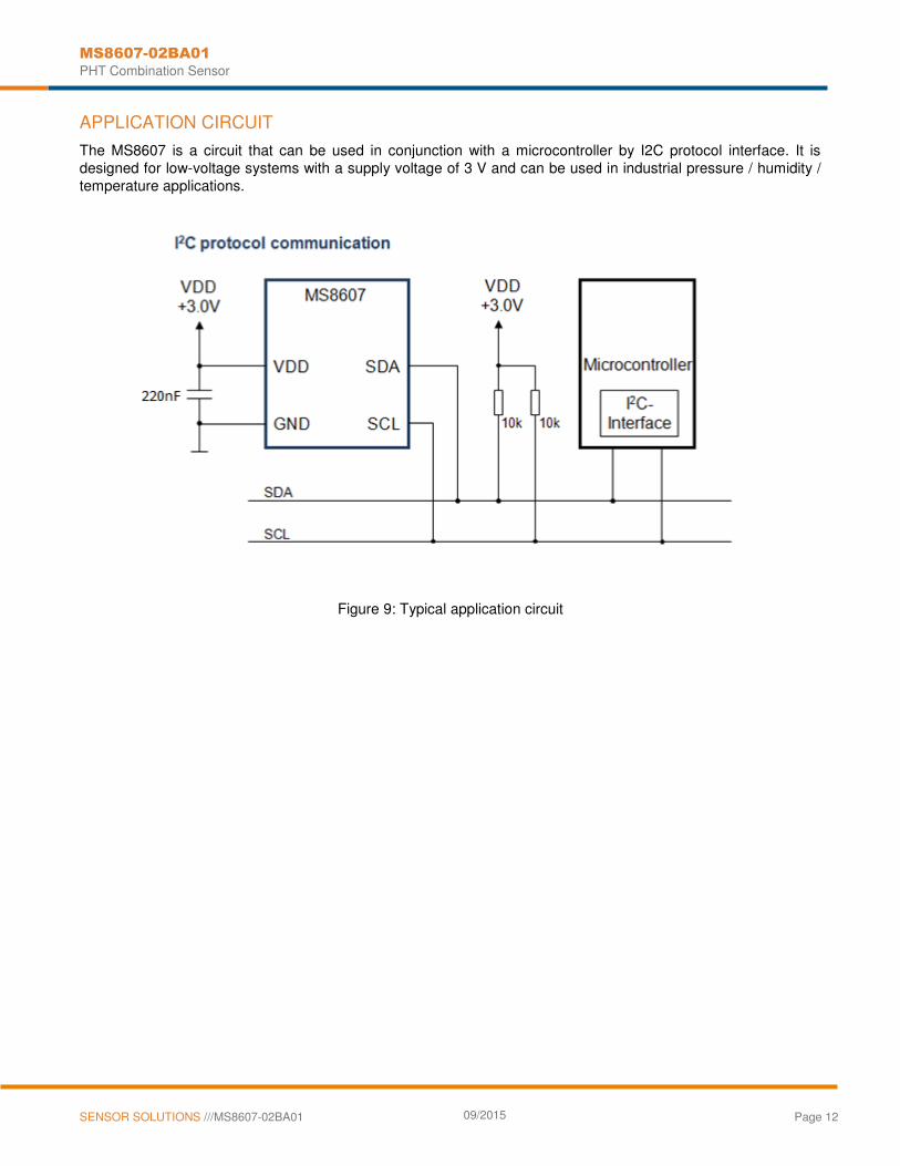
APPLICATION CIRCUIT
The MS8607 is a circuit that can be used in conjunction with a microcontroller by I2C protocol interface. It is designed for low-voltage systems with a supply voltage of 3 V and can be used in industrial pressure / humidity / temperature applications.
Figure 9: Typical application circuit
MS8607-02BA01
PHT Combination Sensor
SENSOR SOLUTIONS ///MS8607-02BA01 09/2015 Page 13
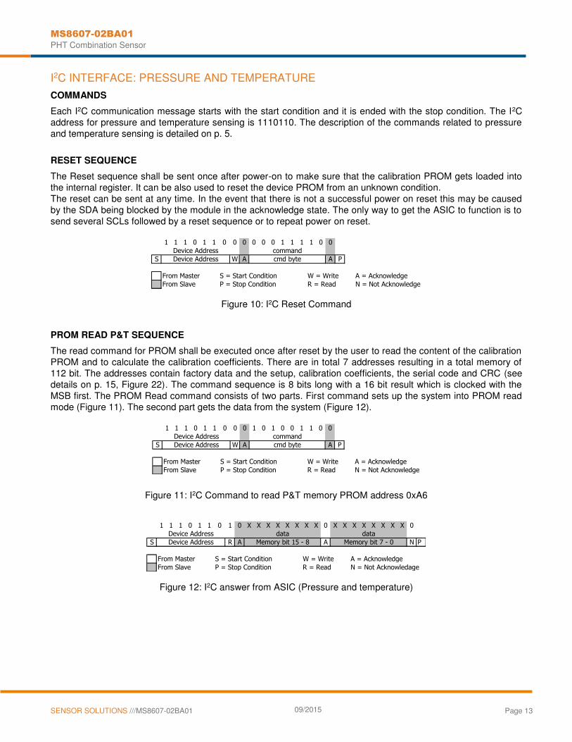
I2C INTERFACE: PRESSURE AND TEMPERATURE
COMMANDS
Each I2C communication message starts with the start condition and it is ended with the stop condition. The I2C address for pressure and temperature sensing is 1110110. The description of the commands related to pressure and temperature sensing is detailed on p. 5.
RESET SEQUENCE
The Reset sequence shall be sent once after power-on to make sure that the calibration PROM gets loaded into the internal register. It can be also used to reset the device PROM from an unknown condition. The reset can be sent at any time. In the event that there is not a successful power on reset this may be caused by the SDA being blocked by the module in the acknowledge state. The only way to get the ASIC to function is to send several SCLs followed by a reset sequence or to repeat power on reset.
Figure 10: I2C Reset Command
PROM READ P&T SEQUENCE
The read command for PROM shall be executed once after reset by the user to read the content of the calibration PROM and to calculate the calibration coefficients. There are in total 7 addresses resulting in a total memory of 112 bit. The addresses contain factory data and the setup, calibration coefficients, the serial code and CRC (see details on p. 15, Figure 22). The command sequence is 8 bits long with a 16 bit result which is clocked with the MSB first. The PROM Read command consists of two parts. First command sets up the system into PROM read mode (Figure 11). The second part gets the data from the system (Figure 12).
Figure 11: I2C Command to read P&T memory PROM address 0xA6
Figure 12: I2C answer from ASIC (Pressure and temperature)
1 1 1 0 1 1 0 0 0 0 0 0 1 1 1 1 0 0
S W A A P
From Master S = Start Condition W = Write A = Acknowledge
From Slave P = Stop Condition R = Read N = Not Acknowledge
cmd byte
Device Address
Device Address
command
1 1 1 0 1 1 0 0 0 1 0 1 0 0 1 1 0 0
S W A A P
From Master S = Start Condition W = Write A = Acknowledge
From Slave P = Stop Condition R = Read N = Not Acknowledge
Device Address
Device Address cmd byte
command
1 1 1 0 1 1 0 1 0 X X X X X X X X 0 X X X X X X X X 0
S R A A N P
From Master S = Start Condition W = Write A = Acknowledge
From Slave P = Stop Condition R = Read N = Not Acknowledage
Memory bit 7 - 0
Device Address
Device Address Memory bit 15 - 8
data data

MS8607-02BA01
PHT Combination Sensor
SENSOR SOLUTIONS ///MS8607-02BA01 09/2015 Page 14
CONVERSION SEQUENCE
The conversion command is used to initiate uncompensated pressure (D1) or uncompensated temperature (D2) conversion. After the conversion, using ADC read command the result is clocked out with the MSB first. If the conversion is not executed before the ADC read command, or the ADC read command is repeated, it will give 0 as the output result. If the ADC read command is sent during conversion the result will be 0, the conversion will not stop and the final result will be wrong. Conversion sequence sent during the already started conversion process will yield incorrect result as well. A conversion can be started by sending the command to the ASIC. When the command is sent to the system it stays busy until conversion is done. When conversion is finished, the data can be accessed by sending a Read command. When the Acknowledge bit is sent from the ASIC, 24 SCL cycles may be sent to receive all result bits. Every 8 bits the system waits for the Acknowledge bit.
Figure 13: I2C command to initiate a pressure conversion (OSR=4096, typ=D1)
Figure 14: I2C ADC read sequence
Figure 15: I2C answer from the ASIC
1 1 1 0 1 1 0 0 0 0 1 0 0 1 0 0 0 0
S W A A P
From Master S = Start Condition W = Write A = Acknowledge
From Slave P = Stop Condition R = Read N = Not Acknowledge
cmd byte
Device Address
Device Address
command
1 1 1 0 1 1 0 0 0 0 0 0 0 0 0 0 0 0
S W A A P
From Master S = Start Condition W = Write A = Acknowledge
From Slave P = Stop Condition R = Read N = Not Acknowledge
Device Address
Device Address cmd byte
command
1 1 1 0 1 1 0 1 0 X X X X X X X X 0 X X X X X X X X 0 X X X X X X X X 0
S R A A A N P
From Master S = Start Condition W = Write A = Acknowledge
From Slave P = Stop Condition R = Read N = Not Acknowledge
Data 23 - 16 Data 7 - 0Data 15 - 8Device Address
Device Address

MS8607-02BA01
PHT Combination Sensor
SENSOR SOLUTIONS ///MS8607-02BA01 09/2015 Page 15
I2C INTERFACE: RELATIVE HUMIDITY
COMMANDS
Each I2C communication message starts with the start condition and it is ended with the stop condition. The I2C address for humidity sensing is 1000000. The description of the commands related to humidity sensing is detailed on p. 6.
RESET SEQUENCE
This command is used for rebooting the humidity sensor by switching the power off and on again. Upon reception of this command, the humidity sensor system reinitializes and starts operation according to the default settings with the exception of the heater bit in the user register. The reset takes less than 15ms.
Figure 16: I2C Reset Command
READ AND WRITE USER REGISTER SEQUENCE
The following sequence illustrates how to read and write the user register. First, it reads the content of the user register. Then it writes the user register for configuring the humidity sensor to 8 bits measurement resolution from the default configuration.
Figure 17: I2C read and write user register commands
1 0 0 0 0 0 0 0 0 1 1 1 1 1 1 1 0 0
S W A A P
From Master S = Start Condition W = Write A = Acknowledge
From Slave P = Stop Condition R = Read N = Not Acknowledge
Device Address cmd byte
commandDevice Address
1 0 0 0 0 0 0 0 0 1 1 1 0 0 1 1 1 0
S W A A
1 0 0 0 0 0 0 1 0 X X X X X X X X 0
S R A N
1 0 0 0 0 0 0 0 0 1 1 1 0 0 1 1 0 0 0 0 0 0 0 0 0 1 0
S W A A A P
From Master S = Start Condition W = Write A = Acknowledge
From Slave P = Stop Condition R = Read N = Not Acknowledge
command
Device Address
Device Address User Register Data 7 - 0
Device Address command
Device Address cmd byte User Register Data 7 - 0
Device Address cmd byte
Device Address

MS8607-02BA01
PHT Combination Sensor
SENSOR SOLUTIONS ///MS8607-02BA01 09/2015 Page 16
MEASURE RH HOLD/NO HOLD SEQUENCE
MS8607 has two different operation modes to measure relative humidity (RH): Hold Master mode and No Hold Master mode.
No Hold Master mode allows for processing other I²C communication tasks on a bus while the humidity sensor is measuring. Figure 18 and 19 illustrate the communication sequence of both modes. In the Hold Master mode, the humidity sensor pulls down the SCK line while measuring to force the master into a wait state. By releasing the SCK line, the humidity sensor indicates that internal processing is completed and that transmission may be continued.
In the No Hold Master mode, the MCU has to poll for the termination of the internal processing of the humidity sensor. This is done by sending a start condition followed by the I²C header (0x81) as shown below. If the internal processing is finished, the humidity sensor acknowledges the poll of the MCU and data can be read by the MCU. If the measurement processing is not finished, the humidity sensor answers the Not Acknowledge bit and start condition must be issued once more.
For both modes, the measurement is stored into 14 bits. The two remaining least significant bits (LSBs) are used for transmitting status information. Bit1 of the two LSBs must be set to ‘1’. Bit0 is currently not assigned.
Figure 18: I2C Measure RH Hold Master communication sequence
Figure 19: I2C Measure RH No Hold Master communication sequence
For Hold Master sequence, the Acknowledge bit that follows the Status bit may be changed to Not Acknowledge bit followed by a stop condition to omit checksum transmission.
For No Hold Master sequence, if measurement is not completed upon “read” command, sensor does not provide ACK on bit 27 (more of these iterations are possible). If bit 45 is changed to NACK followed by stop condition, checksum transmission is omitted.
1 0 0 0 0 0 0 0 0 1 1 1 0 0 1 0 1 0
S W A A
1 0 0 0 0 0 0 1 0 X X X X X X X X 0 X X X X X X 1 0 0
Hold during measurement
S R A A A
1 0 0 1 0 1 1 1 0 From Master S = Start Condition W = Write A = Acknowledge
From Slave P = Stop Condition R = Read N = Not Acknowledge
Checksum N P On hold
Device Address command
Device Address cmd byte
Device Address
Data 15 - 8 Data 7 - 2 StatusDevice Address Hold during measurement
1 0 0 0 0 0 0 0 0 1 1 1 1 0 1 0 1 0
S W A A
1 0 0 0 0 0 0 1 0 X X X X X X X X 0 X X X X X X 1 0 0 1 0 0 1 0 1 1 1 0
S R A A A Checksum N P
From Master S = Start Condition W = Write A = Acknowledge
From Slave P = Stop Condition R = Read N = Not Acknowledge
Data 7 - 2 Status
Device Address cmd byte
Device Address
Device Address command
Device Address Data 15 - 8
MS8607-02BA01
PHT Combination Sensor
SENSOR SOLUTIONS ///MS8607-02BA01 09/2015 Page 17
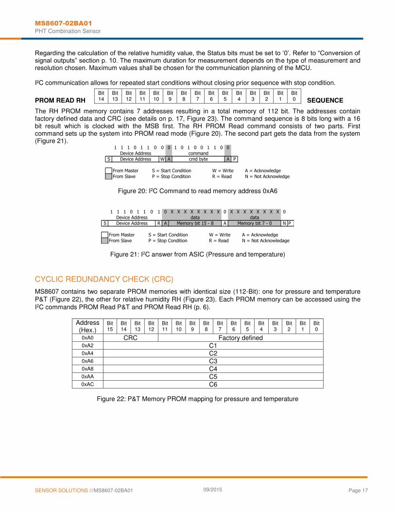
Regarding the calculation of the relative humidity value, the Status bits must be set to ‘0’. Refer to “Conversion of signal outputs” section p. 10. The maximum duration for measurement depends on the type of measurement and resolution chosen. Maximum values shall be chosen for the communication planning of the MCU. I²C communication allows for repeated start conditions without closing prior sequence with stop condition.
PROM READ RH SEQUENCE
The RH PROM memory contains 7 addresses resulting in a total memory of 112 bit. The addresses contain factory defined data and CRC (see details on p. 17, Figure 23). The command sequence is 8 bits long with a 16 bit result which is clocked with the MSB first. The RH PROM Read command consists of two parts. First command sets up the system into PROM read mode (Figure 20). The second part gets the data from the system (Figure 21).
Figure 20: I2C Command to read memory address 0xA6
Figure 21: I2C answer from ASIC (Pressure and temperature)
CYCLIC REDUNDANCY CHECK (CRC)
MS8607 contains two separate PROM memories with identical size (112-Bit): one for pressure and temperature P&T (Figure 22), the other for relative humidity RH (Figure 23). Each PROM memory can be accessed using the I2C commands PROM Read P&T and PROM Read RH (p. 6).
Address (Hex.)
Bit 15
Bit 14
Bit 13
Bit 12
Bit 11
Bit 10
Bit 9
Bit 8
Bit 7
Bit 6
Bit 5
Bit 4
Bit 3
Bit 2
Bit 1
Bit 0
0xA0 CRC Factory defined 0xA2 C1 0xA4 C2 0xA6 C3 0xA8 C4 0xAA C5 0xAC C6
Figure 22: P&T Memory PROM mapping for pressure and temperature
1 1 1 0 1 1 0 0 0 1 0 1 0 0 1 1 0 0
S W A A P
From Master S = Start Condition W = Write A = Acknowledge
From Slave P = Stop Condition R = Read N = Not Acknowledge
Device Address
Device Address cmd byte
command
1 1 1 0 1 1 0 1 0 X X X X X X X X 0 X X X X X X X X 0
S R A A N P
From Master S = Start Condition W = Write A = Acknowledge
From Slave P = Stop Condition R = Read N = Not Acknowledage
Memory bit 7 - 0
Device Address
Device Address Memory bit 15 - 8
data data
Bit 14
Bit 13
Bit 12
Bit 11
Bit 10
Bit 9
Bit 8
Bit 7
Bit 6
Bit 5
Bit 4
Bit 3
Bit 2
Bit 1
Bit 0
MS8607-02BA01
PHT Combination Sensor
SENSOR SOLUTIONS ///MS8607-02BA01 09/2015 Page 18
Address (Hex.)
Bit 15
Bit 14
Bit 13
Bit 12
Bit 11
Bit 10
Bit 9
Bit 8
Bit 7
Bit 6
Bit 5
Bit 4
Bit 3
Bit 2
Bit 1
Bit 0
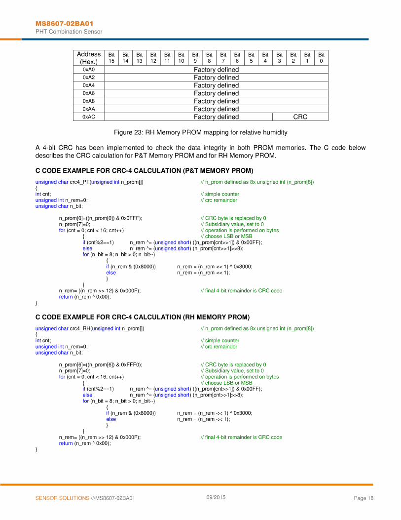
0xA0 Factory defined 0xA2 Factory defined 0xA4 Factory defined 0xA6 Factory defined 0xA8 Factory defined 0xAA Factory defined 0xAC Factory defined CRC
Figure 23: RH Memory PROM mapping for relative humidity
A 4-bit CRC has been implemented to check the data integrity in both PROM memories. The C code below describes the CRC calculation for P&T Memory PROM and for RH Memory PROM. C CODE EXAMPLE FOR CRC-4 CALCULATION (P&T MEMORY PROM)
unsigned char crc4_PT(unsigned int n_prom[]) // n_prom defined as 8x unsigned int (n_prom[8]) { int cnt; // simple counter unsigned int n_rem=0; // crc remainder unsigned char n_bit; n_prom[0]=((n_prom[0]) & 0x0FFF); // CRC byte is replaced by 0 n_prom[7]=0; // Subsidiary value, set to 0 for (cnt = 0; cnt < 16; cnt++) // operation is performed on bytes { // choose LSB or MSB if (cnt%2==1) n_rem ^= (unsigned short) ((n_prom[cnt>>1]) & 0x00FF); else n_rem ^= (unsigned short) (n_prom[cnt>>1]>>8); for (n_bit = 8; n_bit > 0; n_bit--) { if (n_rem & (0x8000)) n_rem = (n_rem << 1) ^ 0x3000; else n_rem = (n_rem << 1); } } n_rem= ((n_rem >> 12) & 0x000F); // final 4-bit remainder is CRC code return (n_rem ^ 0x00); }
C CODE EXAMPLE FOR CRC-4 CALCULATION (RH MEMORY PROM)
unsigned char crc4_RH(unsigned int n_prom[]) // n_prom defined as 8x unsigned int (n_prom[8]) { int cnt; // simple counter unsigned int n_rem=0; // crc remainder unsigned char n_bit; n_prom[6]=((n_prom[6]) & 0xFFF0); // CRC byte is replaced by 0 n_prom[7]=0; // Subsidiary value, set to 0 for (cnt = 0; cnt < 16; cnt++) // operation is performed on bytes { // choose LSB or MSB if (cnt%2==1) n_rem ^= (unsigned short) ((n_prom[cnt>>1]) & 0x00FF); else n_rem ^= (unsigned short) (n_prom[cnt>>1]>>8); for (n_bit = 8; n_bit > 0; n_bit--) { if (n_rem & (0x8000)) n_rem = (n_rem << 1) ^ 0x3000; else n_rem = (n_rem << 1); } } n_rem= ((n_rem >> 12) & 0x000F); // final 4-bit remainder is CRC code return (n_rem ^ 0x00); }

MS8607-02BA01
PHT Combination Sensor
SENSOR SOLUTIONS ///MS8607-02BA01 09/2015 Page 19
PIN CONFIGURATION
Pin Name
Type Function
1 VDD P Positive supply voltage
3 GND G Ground
7 SDA IO I2C data IO
8 SCL SCL
I Serial data clock
2,4,5,6 NC
DEVICE PACKAGE OUTLINE
MS8607-02BA01
PHT Combination Sensor
SENSOR SOLUTIONS ///MS8607-02BA01 09/2015 Page 20
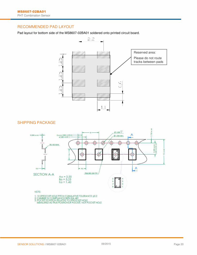
RECOMMENDED PAD LAYOUT
Pad layout for bottom side of the MS8607-02BA01 soldered onto printed circuit board.
SHIPPING PACKAGE
Reserved area:
Please do not route tracks between pads
MS8607-02BA01
PHT Combination Sensor
SENSOR SOLUTIONS ///MS8607-02BA01 09/2015 Page 21
MOUNTING AND ASSEMBLY CONSIDERATIONS
SOLDERING
Please refer to the application note AN808 available on our website for all soldering issues.
MOUNTING
The MS8607 can be placed with automatic Pick & Place equipment using vacuum nozzles. It will not be damaged by the vacuum. Due to the low stress assembly the sensor does not show pressure hysteresis effects. It is important to solder all contact pads.
CONNECTION TO PCB
The package outline of the module allows the use of a flexible PCB for interconnection. This can be important for applications in watches and other special devices.
CLEANING
The MS8607 has been manufactured under cleanroom conditions. It is therefore recommended to assemble the sensor under class 10’000 or better conditions. Should this not be possible, it is recommended to protect the sensor opening during assembly from entering particles and dust. To avoid cleaning of the PCB, solder paste of type “no-clean” shall be used. Cleaning might damage the sensor!
ESD PRECAUTIONS
The electrical contact pads are protected against ESD up to 2 kV HBM (human body model). It is therefore essential to ground machines and personnel properly during assembly and handling of the device. The MS8607 is shipped in antistatic transport boxes. Any test adapters or production transport boxes used during the assembly of the sensor shall be of an equivalent antistatic material.
DECOUPLING CAPACITOR
Particular care must be taken when connecting the device to the power supply. A minimum 220nF ceramic capacitor must be placed as close as possible to the MS8607 VDD pin. This capacitor will stabilize the power supply during data conversion and thus, provide the highest possible accuracy.
MS8607-02BA01
PHT Combination Sensor
SENSOR SOLUTIONS ///MS8607-02BA01 09/2015 Page 22
ORDERING INFORMATION
Part Number / Art. Number Product Delivery Form
MS860702BA01-50 PHT Combination Sensor Module 5x3mm Tape & Reel
TE.com/sensorsolutions
Measurement Specialties, Inc., a TE Connectivity company.
Measurement Specialties, TE Connectivity, TE Connectivity (logo) and EVERY CONNECTION COUNTS are trademarks. All other logos, products and/or company names referred to herein might be trademarks of their respective owners.
The information given herein, including drawings, illustrations and schematics which are intended for illustration purposes only, is believed to be reliable. However, TE Connectivity makes no warranties as to its accuracy or completeness and disclaims any liability in connection with its use. TE Connectivity‘s obligations shall only be as set forth in TE Connectivity‘s Standard Terms and Conditions of Sale for this product and in no case will TE Connectivity be liable for any incidental, indirect or consequential damages arising out of the sale, resale, use or misuse of the product. Users of TE Connectivity products should make their own evaluation to determine the suitability of each such product for the specific application.
© 2015 TE Connectivity Ltd. family of companies All Rights Reserved.
DA8607-02BA01_003
000086072885 ECN2515
NORTH AMERICA
Measurement Specialties, Inc., a TE Connectivity Company 45738 Northport Loop West Fremont, CA 94538 Tel: +1 800 767 1888 Fax: +1 510 498 1578 e-mail: [email protected] Website: www.meas-spec.com
EUROPE
Measurement Specialties (Europe), Ltd., a TE Connectivity Company Switzerland Sàrl Ch. Chapons-des-Prés 11 CH-2022 Bevaix Tel: +41 32 847 9550 Fax: + 41 32 847 9569 e-mail: [email protected] Website: www.meas-spec.com
ASIA
Measurement Specialties (China), Ltd., a TE Connectivity Company No. 26 Langshan Road Shenzhen High-Tech Park (North) Nanshan District, Shenzhen, 518057 China Tel: +86 755 3330 5088 Fax: +86 755 3330 5099 e-mail: [email protected] Website: www.meas-spec.com