ms training manual lgr 12-04-2017 vk -...
TRANSCRIPT

MS Training Manual
1
Storage, installation and maintenance for
MS busbar systems

MS Training Manual
2
INDEX
STORAGE INSTRUCTIONS .................................................... 4
HANDLING .......................................................................... 4
GOOD RECEPTION ................................................................ 5
NOTIFICATIONS ................................................................... 5
STORAGE ............................................................................ 6
INSTALLATION INSTRUCTIONS ........................................... 7
STRAIGHT LENGHTS & FLEXIBLE JOINT ................................... 9
ELBOW ELEMENT ................................................................ 10
FEED UNITS ....................................................................... 11
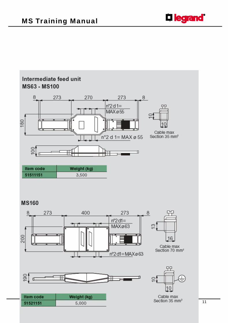
INTERMEDIATE FEED UNIT ................................................... 12
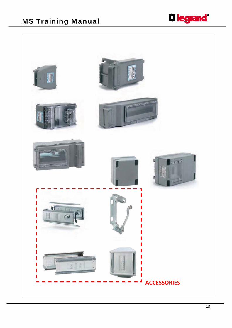
FIXING ACCESSORIES & TAP-OFF BOXES .......................... 14/19
PREPARATION OF THE END FEED UNIT ................................... 20
ASSEMBLY OF AN IP40 INSTALLATION ................................... 23
END COVER ASSEMBLY ........................................................ 25
ASSEMBLY OF AN IP55 INSTALLATION ................................... 26
PREPARATION OF 16A TAP-OFF UNITS ................................... 28
PREPARATION OF 25/50A TAP-OFF UNITS .............................. 30
PREPARATION OF 63A TAP-OFF UNITS ................................... 32
FIRE BARRIER ..................................................................... 35
INSPECTION, CONTROL AND MAINTENANCE INSTRUCTIONS FOR PLANTS WITH MS BUS DUCT........................................36

MS Training Manual
3
WARNINGS
These instructions are provided to ensure appropriate storage, correct installation, and efficient use of the system. Note: carefully read these instructions upon receipt of the material and before installing the system, and putting it into operation. The installation must be completed by competent and suitably trained personnel, as prescribed by CEI 11-27 and 50110-1:2004-11 (CEI 11-48) standards, corresponding international standards, or specific applicable standards of the individual countries of installation. In order to guarantee the safety of personnel, the installation activities must only be carried out with the power voltage disconnected, unless otherwise stated. WARNING When working with electric systems, pay particular attention to the risk of electric shock. Electric shocks can cause serious injury, or even death. NOTE: Do not tamper or perform modifications to products manufactured by BTicino S.p.A. without written authorization by manufacturer. BTicino S.p.A. does not authorize any kind of repairs. All tampering, or modifications not authorized in writing by BTicino S.p.A. will void the product warranty.
MS Training Manual
4
STORAGE INSTRUCTIONS
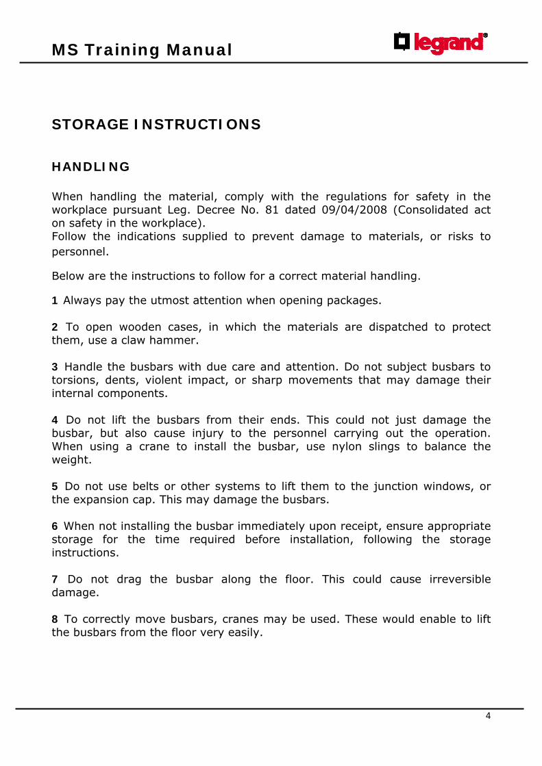
HANDLING When handling the material, comply with the regulations for safety in the workplace pursuant Leg. Decree No. 81 dated 09/04/2008 (Consolidated act on safety in the workplace). Follow the indications supplied to prevent damage to materials, or risks to personnel.
Below are the instructions to follow for a correct material handling.
1 Always pay the utmost attention when opening packages. 2 To open wooden cases, in which the materials are dispatched to protect them, use a claw hammer. 3 Handle the busbars with due care and attention. Do not subject busbars to torsions, dents, violent impact, or sharp movements that may damage their internal components. 4 Do not lift the busbars from their ends. This could not just damage the busbar, but also cause injury to the personnel carrying out the operation. When using a crane to install the busbar, use nylon slings to balance the weight. 5 Do not use belts or other systems to lift them to the junction windows, or the expansion cap. This may damage the busbars. 6 When not installing the busbar immediately upon receipt, ensure appropriate storage for the time required before installation, following the storage instructions. 7 Do not drag the busbar along the floor. This could cause irreversible damage. 8 To correctly move busbars, cranes may be used. These would enable to lift the busbars from the floor very easily.
MS Training Manual
5
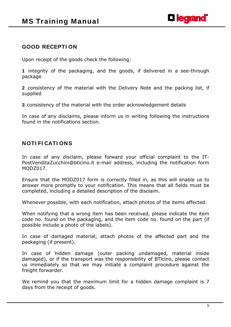
GOOD RECEPTION Upon receipt of the goods check the following: 1 integrity of the packaging, and the goods, if delivered in a see-through package 2 consistency of the material with the Delivery Note and the packing list, if supplied 3 consistency of the material with the order acknowledgement details In case of any disclaims, please inform us in writing following the instructions found in the notifications section.
NOTIFICATIONS In case of any disclaim, please forward your official complaint to the [email protected] e-mail address, including the notification form MODZ017. Ensure that the MODZ017 form is correctly filled in, as this will enable us to answer more promptly to your notification. This means that all fields must be completed, including a detailed description of the disclaim. Whenever possible, with each notification, attach photos of the items affected. When notifying that a wrong item has been received, please indicate the item code no. found on the packaging, and the item code no. found on the part (if possible include a photo of the labels). In case of damaged material, attach photos of the affected part and the packaging (if present). In case of hidden damage (outer packing undamaged, material inside damaged), or if the transport was the responsibility of BTicino, please contact us immediately so that we may initiate a complaint procedure against the freight forwarder. We remind you that the maximum limit for a hidden damage complaint is 7 days from the receipt of goods.
MS Training Manual
6
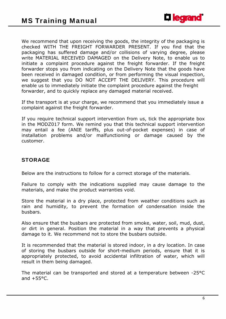
We recommend that upon receiving the goods, the integrity of the packaging is checked WITH THE FREIGHT FORWARDER PRESENT. If you find that the packaging has suffered damage and/or collisions of varying degree, please write MATERIAL RECEIVED DAMAGED on the Delivery Note, to enable us to initiate a complaint procedure against the freight forwarder. If the freight forwarder stops you from indicating on the Delivery Note that the goods have been received in damaged condition, or from performing the visual inspection, we suggest that you DO NOT ACCEPT THE DELIVERY. This procedure will enable us to immediately initiate the complaint procedure against the freight forwarder, and to quickly replace any damaged material received. If the transport is at your charge, we recommend that you immediately issue a complaint against the freight forwarder. If you require technical support intervention from us, tick the appropriate box in the MODZ017 form. We remind you that this technical support intervention may entail a fee (ANIE tariffs, plus out-of-pocket expenses) in case of installation problems and/or malfunctioning or damage caused by the customer.
STORAGE Below are the instructions to follow for a correct storage of the materials. Failure to comply with the indications supplied may cause damage to the materials, and make the product warranties void. Store the material in a dry place, protected from weather conditions such as rain and humidity, to prevent the formation of condensation inside the busbars. Also ensure that the busbars are protected from smoke, water, soil, mud, dust, or dirt in general. Position the material in a way that prevents a physical damage to it. We recommend not to store the busbars outside. It is recommended that the material is stored indoor, in a dry location. In case of storing the busbars outside for short-medium periods, ensure that it is appropriately protected, to avoid accidental infiltration of water, which will result in them being damaged. The material can be transported and stored at a temperature between -25°C and +55°C.

MS Training Manual
7
INSTALLATION INSTRUCTIONS Before the installation, all material should be inspected for damage. When installing the busbars comply with the following: 1 do not position the busbars near pipes containing liquids. 2 for the installation only use bracketing systems supplied by BTicino, and follow the instructions found in the catalogue or enclosed with the item. 3 only use accessories supplied by BTicino. 4 check that the operating voltage coincides with that indicated on the product plate. 5 check that the system operating current does not exceed the product rated current, downgrading it if required. 6 check if the busbar capacity must be downgraded (for example due to high ambient temperature, presence of harmonics, etc.) 7 do not install the standard product in particular environments (high concentration of chlorine, explosive atmosphere, etc.). 8 for outdoor installations, protect the busbar with a protection canopy. The IP55 protection degree can be affected by unsuitably protected outdoor installation. 9 Should the load of the conductors with current “I” be near the nominal capacity , the possibility of electrical disturbance must be accounted for. 10 The area in which the busbar is to be installed must be assessed to see if it is suitable for the type of product that has been chosen ( proximity to excessive heat sources, presence of corrosive fumes, etc).

MS Training Manual
8

MS Training Manual
9
MS Training Manual
10
MS Training Manual
11

MS Training Manual
12
MS Training Manual
13
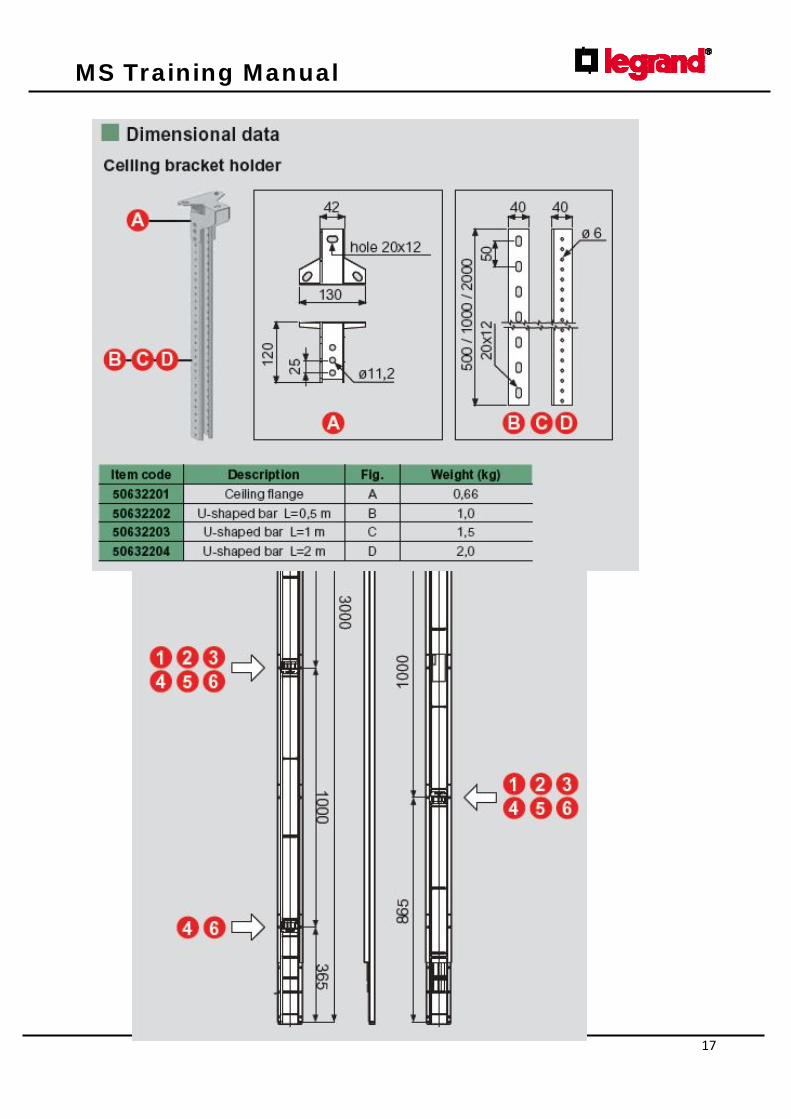
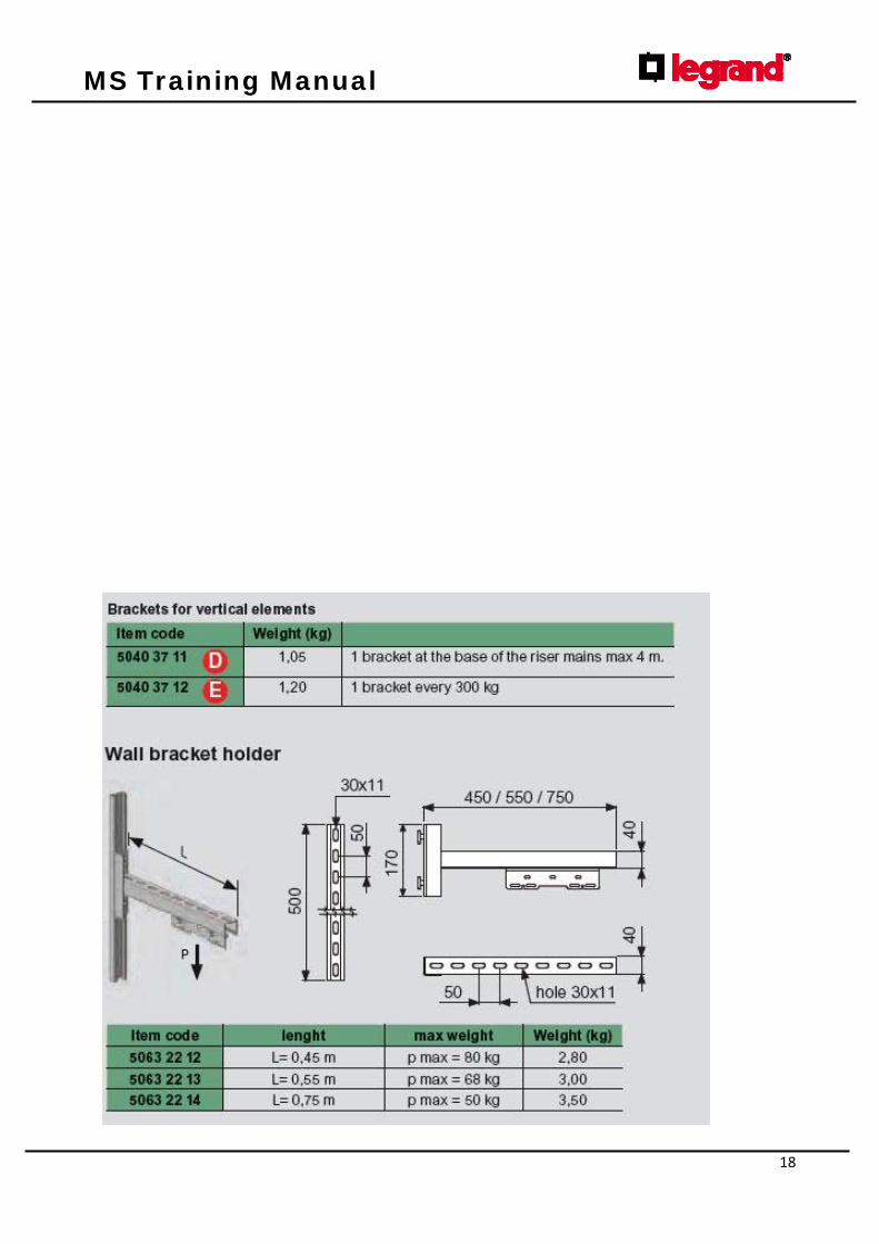
ACCESSORIES

MS Training Manual
14
MS Training Manual
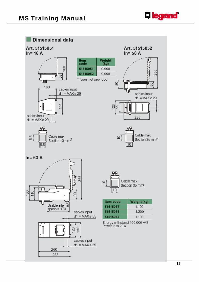
15
MS Training Manual
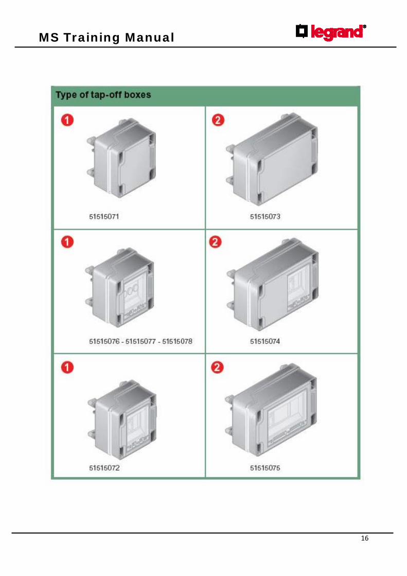
16
MS Training Manual
17
MS Training Manual
18
MS Training Manual
19
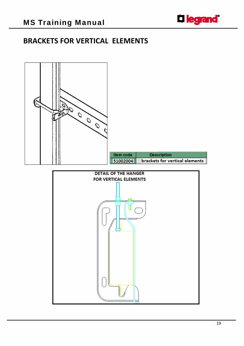
BRACKETS FOR VERTICAL ELEMENTS

MS Training Manual
20
Preparation of the end feed unit
A) PREPARATION OF THE END FEED UNIT
Prepare the LH or RH end feed unit
based on the neutral position.
A1) PREPARATION OF THE END FEED UNIT
Open the feed unit cover. Ensure that it is the
required one , LH or RH according to the
position of Neutral ”N”
A2) PREPARATION OF THE END FEED UNIT
Drill a hole to accommodate the type of
cable fitting to be assembled.
WARNING
Ensure that the cable to be
connected is not energized

MS Training Manual
21
A3) PREPARATION OF THE END FEED UNIT
Allowing a suitable external tolerance,
insert the cable into the cable fitting
(MS100 n°1 Pg36 – MS160 n°2 Pg48
not supplied) and into the end feed
unit.
A4) PREPARATION OF THE END FEED UNIT
Connect the cable conductors
according to the electrical scheme and
tighten the terminals.
A5) PREPARATION OF THE END FEED UNIT
Fasten the cable with the cable clamp
and tighten the dedicated screws.
A6) PREPARATION OF THE END FEED UNIT
Re‐fit the end fit cover.
MS Training Manual
22
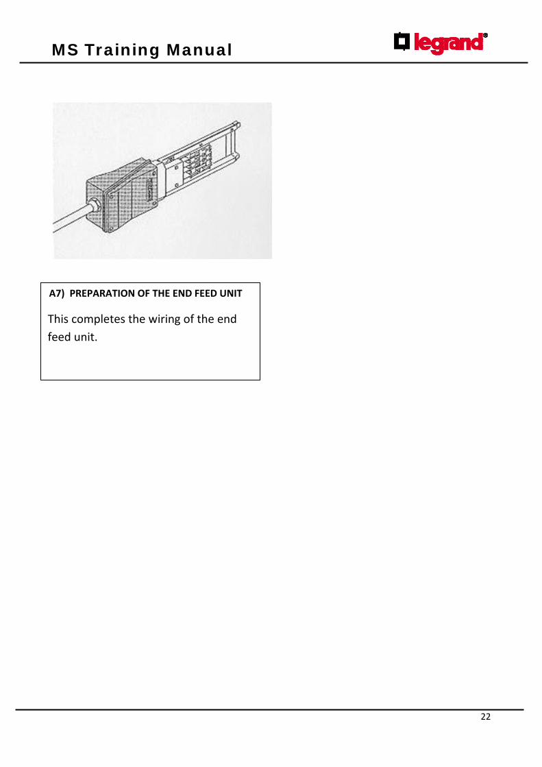
A7) PREPARATION OF THE END FEED UNIT
This completes the wiring of the end
feed unit.

MS Training Manual
23
Assembly of an IP40 installation
B) ASSEMBLY OF AN IP40 INSTALLATION
Ground set the straight lengths
according to the direction of the joints
and neutral position.
B1) ASSEMBLY OF AN IP40 INSTALLATION
Overlap and join the two straight lengths
using a slight pressure as shown in the
drawing.
B2) ASSEMBLY OF AN IP40 INSTALLATION
Fasten the lengths with the 6 screws
provided and tighten completely.
B3) ASSEMBLY OF AN IP40 INSTALLATION
Warning check that connection blades
are well in contact with each other.

MS Training Manual
24
B4) ASSEMBLY OF AN IP40 INSTALLATION
Join other corresponding components by
following the instructions given in points
B1,B2,B3. Based on the course to follow
and the neutral position, choose the
most suitable component.
B6) ASSEMBLY OF AN IP40 INSTALLATION
According to neutral “N” connect the
previously prepared RH or LH end feed
unit (see preparation of end feed unit)
and act as per straight lengths tightening
the 6 screws properly.
WARNING :the mechanical casing joint
screws must be properly tightened to
ensure maximum continuity of the
protective circuit (PE)
B5) ASSEMBLY OF AN IP40 INSTALLATION
Fasten the suspension clamps to the
lengths and assemble them.
MS Training Manual
25
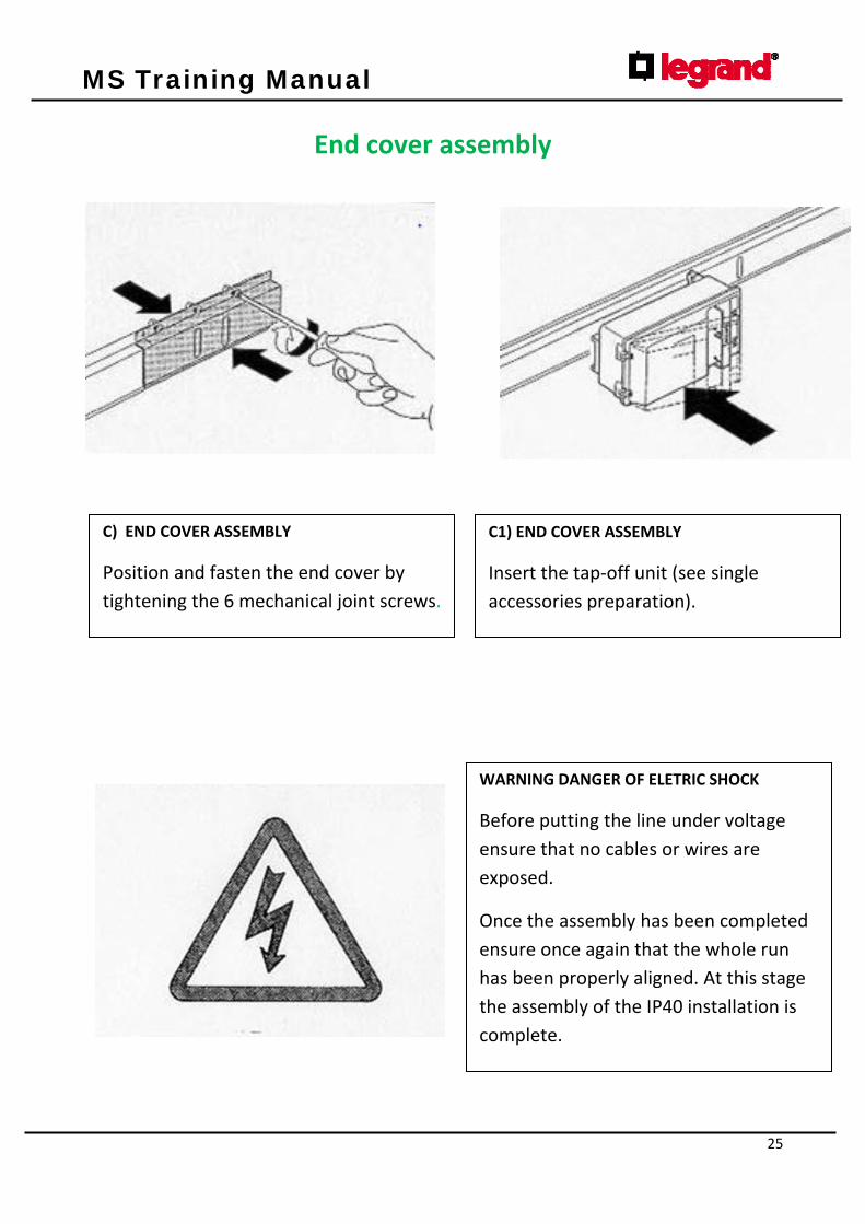
End cover assembly
C) END COVER ASSEMBLY
Position and fasten the end cover by
tightening the 6 mechanical joint screws.
C1) END COVER ASSEMBLY
Insert the tap‐off unit (see single
accessories preparation).
WARNING DANGER OF ELETRIC SHOCK
Before putting the line under voltage
ensure that no cables or wires are
exposed.
Once the assembly has been completed
ensure once again that the whole run
has been properly aligned. At this stage
the assembly of the IP40 installation is
complete.
MS Training Manual
26
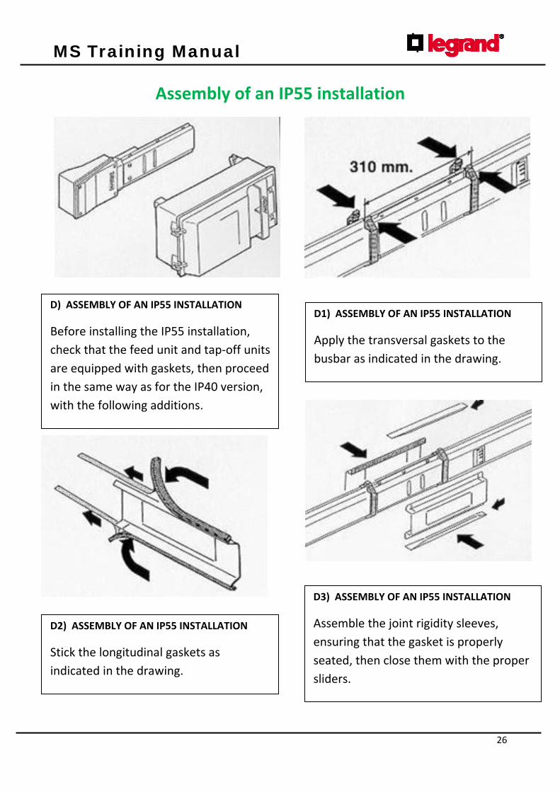
Assembly of an IP55 installation
D) ASSEMBLY OF AN IP55 INSTALLATION
Before installing the IP55 installation,
check that the feed unit and tap‐off units
are equipped with gaskets, then proceed
in the same way as for the IP40 version,
with the following additions.
D1) ASSEMBLY OF AN IP55 INSTALLATION
Apply the transversal gaskets to the
busbar as indicated in the drawing.
D2) ASSEMBLY OF AN IP55 INSTALLATION
Stick the longitudinal gaskets as
indicated in the drawing.
D3) ASSEMBLY OF AN IP55 INSTALLATION
Assemble the joint rigidity sleeves,
ensuring that the gasket is properly
seated, then close them with the proper
sliders.
MS Training Manual
27
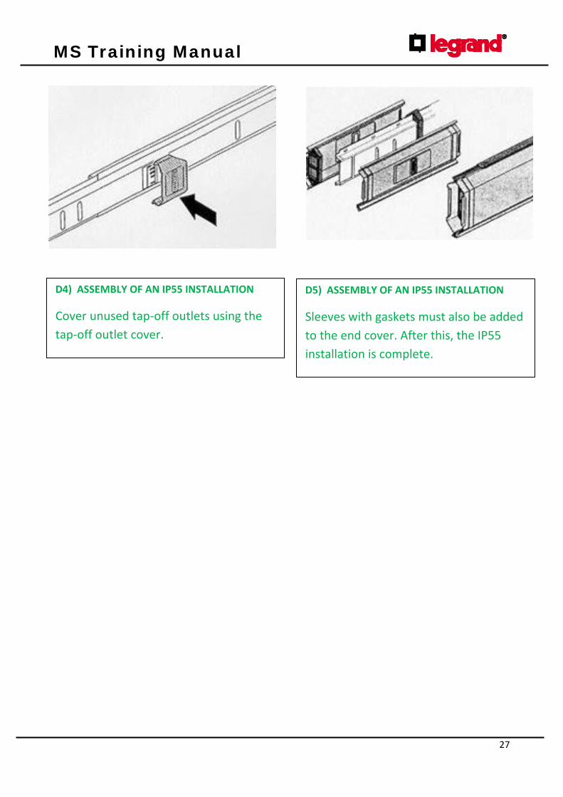
D4) ASSEMBLY OF AN IP55 INSTALLATION
Cover unused tap‐off outlets using the
tap‐off outlet cover.
D5) ASSEMBLY OF AN IP55 INSTALLATION
Sleeves with gaskets must also be added
to the end cover. After this, the IP55
installation is complete.

MS Training Manual
28
Preparation of 16A tap‐off units
E) PREPARATION OF 16A TAP‐OFF UNITS
Make a hole according to the cable
grommet to be assembled (Max 1+1
Pg21).
E1) PREPARATION OF 16A TAP‐OFF UNITS
Unscrew the screw, open the cover and
remove any remaining residue caused by
the drilling of the unit.
E2) PREPARATION OF 16A TAP‐OFF UNITS
Insert the cable into the cable grommet,
connect the cable conductors according
to the electrical scheme and tighten the
clamps well.
E3) PREPARATION OF 16A TAP‐OFF UNITS
Insert the fuses (CH 10X32) into the
correct holders.
MS Training Manual
29
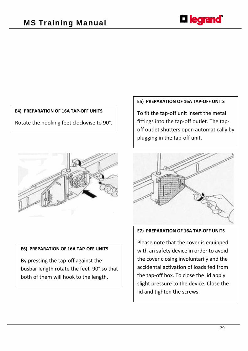
E4) PREPARATION OF 16A TAP‐OFF UNITS
Rotate the hooking feet clockwise to 90°.
E5) PREPARATION OF 16A TAP‐OFF UNITS
To fit the tap‐off unit insert the metal
fittings into the tap‐off outlet. The tap‐
off outlet shutters open automatically by
plugging in the tap‐off unit.
E6) PREPARATION OF 16A TAP‐OFF UNITS
By pressing the tap‐off against the
busbar length rotate the feet 90° so that
both of them will hook to the length.
E7) PREPARATION OF 16A TAP‐OFF UNITS
Please note that the cover is equipped
with an safety device in order to avoid
the cover closing involuntarily and the
accidental activation of loads fed from
the tap‐off box. To close the lid apply
slight pressure to the device. Close the
lid and tighten the screws.

MS Training Manual
30
Preparation of 25/50A tap‐off unit
F) PREPARATION OF 25/50A TAP‐OFF UNITS
Make a hole according to the cable
grommet which is to be assembled (Max
Pg29).
F1) PREPARATION OF 25/50A TAP‐OFF UNITS
Unscrew the screw, open the cover and
remove any remaining residue caused by
the drilling of the unit.
F2) PREPARATION OF 25/50A TAP‐OFF UNITS
Insert the cable into the cable grommet,
connect the cable conductors according
to the electrical scheme and tighten the
clamps well.
F3) PREPARATION OF 25/50A TAP‐OFF UNITS
Insert the fuses (CH 14X51) into the
correct holders.

MS Training Manual
31
F4) PREPARATION OF 25/50A TAP‐OFF UNITS
Respecting the sense of assembling,
insert the metal fittings into the tap‐off
outlet keeping the fixing arms pressed in.
F5) PREPARATION OF 25/50A TAP‐OFF UNITS
The tap‐off outlet shutters open
automatically by plugging in the tap‐off
unit.
F6) PREPARATION OF 25/50A TAP‐OFF UNITS
Please note that the cover is equipped
with an safety device in order to avoid
the cover closing involuntarily and the
accidental activation of loads fed from
the tap‐off box. To close the lid apply
slight pressure to the device. Close the
lid and tighten the screws.

MS Training Manual
32
Preparation of 63A tap‐off unit
G) PREPARATION OF 63A TAP‐OFF UNITS
(BASE & CIRCUIT BRAKER PREPARATION)
Make a hole according to the cable
grommet which is to be assembled(Max
Pg36).
G1) PREPARATION OF 63A TAP‐OFF UNITS
(BASE & CIRCUIT BRAKER PREPARATION)
Unscrew the screws, open the cover and
(only on the version with circuit
breakers) remove the accessories.
Remove any remaining residue caused
by the drilling of the unit.
G2) PREPARATION OF 63A TAP‐OFF UNITS (BASE &
CIRCUIT BRAKER PREPARATION)
Insert the cable through the cable grommet,
connect the cable conductors according to the
electrical scheme and tighten the clamps well.
(only on the version with circuit breakers
assemble the Din rail according to the
instructions found inside. After this, the
electric connection must be carried out on the
circuit breaker and the unit terminals).
G3) PREPARATION OF 63A TAP‐OFF UNITS
(BASE & CIRCUIT BRAKER PREPARATION)
The internal plate may also be used for
fixing auxiliary equipment as long as it is
of suitable dimensions.

MS Training Manual
33
G4) PREPARATION OF 63A TAP‐OFF UNITS
(BASE & CIRCUIT BRAKER PREPARATION)
Rotate the hooking feet 90° (towards the
label). Assemble the two fastened
metallic feet onto the tap‐off unit.
G5) PREPARATION OF 63A TAP‐OFF UNITS
(BASE & CIRCUIT BRAKER PREPARATION)
Respecting the sense of assembling,
insert the metal fittings into the tap‐off
outlet keeping the fixing arms pressed in.
The tap‐off outlet shutters open
automatically by plugging in the tap‐off
unit.
G6) PREPARATION OF 63A TAP‐OFF UNITS
(BASE & CIRCUIT BRAKER PREPARATION)
Rotate the feet 90° so that both of them
will hook to the busbar length.
MS Training Manual
34
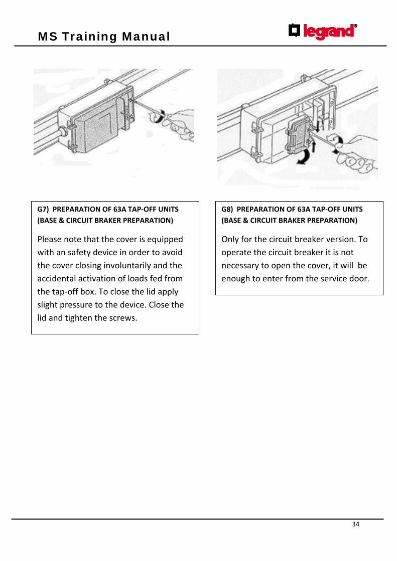
G7) PREPARATION OF 63A TAP‐OFF UNITS
(BASE & CIRCUIT BRAKER PREPARATION)
Please note that the cover is equipped
with an safety device in order to avoid
the cover closing involuntarily and the
accidental activation of loads fed from
the tap‐off box. To close the lid apply
slight pressure to the device. Close the
lid and tighten the screws.
G8) PREPARATION OF 63A TAP‐OFF UNITS
(BASE & CIRCUIT BRAKER PREPARATION)
Only for the circuit breaker version. To
operate the circuit breaker it is not
necessary to open the cover, it will be
enough to enter from the service door.
MS Training Manual
35
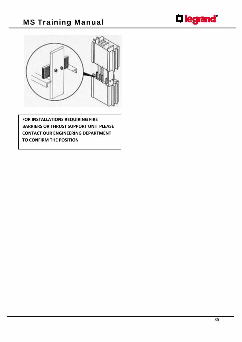
FOR INSTALLATIONS REQUIRING FIRE
BARRIERS OR THRUST SUPPORT UNIT PLEASE
CONTACT OUR ENGINEERING DEPARTMENT
TO CONFIRM THE POSITION

MS Training Manual
36
INSPECTION, CONTROL AND MAINTENANCE INSTRUCTIONS FOR PLANTS WITH MS BUS DUCT
BUS DUCT INSPECTIONS AFTER INSTALLATION
ELECTRICAL SAFETY TESTS
Carry out all tests described in the applicable technical installation standards, such as the insulating test between phases and to earth at 500 V with a minimum value of 10 MΩ, for every line stretch.
If the insulating value is lower than 10 MΩ, it is necessary to verify the plant completely, starting from the insulating parts of each block. If the insulation is still inadequate, divide the plant in two parts and verify the single stretch to identify the element with low insulation. Continue the splitting, if the insulation keeps being inadequate.
If isulation test is made to every peice the value minimal is 50 MOhm.
THERMAL TESTS
After having run the plant at the maximum working current, and having let it work for at least 6 hours, carry out a thermal test. Stick labels on the hottest parts and mark them with progressive numbers to identify the element. Carry out the thermal test again on the labels.
Thermal tests can be carried out with contact temperature sensors, with optical pyrometers or thermal cameras.

MS Training Manual
37
BUS DUCT ANNUAL PERIODIC INSPECTIONS TO BE CARRIED OUT ONE YEAR AFTER ENERGIZING AND EVERY OTHER FOLLOWING YEAR
THERMAL TESTS
After having run the plant at the maximum working current for at least 6 hours, carry out a thermal test, taking in particular consideration the points where labels had been glued during installation (See previous point). If the measured temperature (DT = Tmeasured - Tambient) is higher than 55 K or is 15 K higher than the temperature measured during installation, contact the Customer Care for the Zucchini Brand. This thermal test can be carried out with contact temperature sensors, optical pyrometers or thermal cameras.
TAP-OFF BOXES INSPECTIONS AFTER INSTALLATION
These inspections have to be always carried out with a non-energized plant and after having earthed the phases of the tap-off box, in order to unload possible static discharges in the downstream circuit (with an insulated device).
Plug-in
Verify the contact resistance between the clamp before the protective device and the relative bar in the up-river outlet. If resistance is higher than 50µOhm, the tap-off box could have been mounted incorrectly. Take off the tap-off box, verify the plug-block and the outlet of the element. If the outlet is broken and the contacts have entered the bulb, replace the box and mark the outlet as out of service. Insert a new box in another outlet and do not use the broken one again.
N.B. Never use an outlet when problems have occurred during the installation of the tap-off box, or when the tap-off box has been replaced because it was out of service.

MS Training Manual
38
THERMAL TESTS
Carry out a thermal test on the cover near the lock, using contact temperature sensors, optical pyrometers or thermal cameras. The test has to be carried out with tap-off boxes that have been running at working current for at least 6 hours.
TAP-OFF BOXES ANNUAL PERIODIC INSPECTIONS
Carry out a thermal test on the cover near the lock, using contact temperature sensors, optical pyrometers or thermal cameras. The test has to be carried out with tap-off boxes that have been running at working current for at least 6 hours.
If the measured relative temperature (DT = Tmeasured - Tambient) is higher than 55 K or is 15 K higher than the temperature measured during installation, contact the Customer Care for the Zucchini Brand. Verify if joining screws are correctly tightened.
For further information or explanations please contact our Customer Care for the Zucchini Brand.
Tel: 0365 332811 Fax: 0365 31934 E-mail: [email protected]