ms series iv - magna-power
TRANSCRIPT
OPERATING AND SERVICE MANUAL
MS SERIES IV
DC POWER SUPPLIES


MAGNA-POWER ELECTRONICS, INC.39 ROYAL ROAD, FLEMINGTON, NJ 08822
February 20, 2012


SAFETY NOTICE
Before applying power to the system, verify that the unit is configured properly for the user’sparticular application.
Two or more MS Series power supplies may be connected in series. For models rated 1000 Vor less and regardless of the number of units or the voltage ratings of the series connected powersupplies, the voltage potential from any output terminal to chassis ground should not exceed1000 Vdc. For models rated greater that 1000 V and regardless of the number of units or thevoltage ratings of the series connected power supplies, the voltage potential from any outputterminal to chassis ground should not exceed 2000 Vdc + VO/2 where VO is the output voltageof the power supply.
Installation and service must be performed only by properly trained and qualified personnel whoare aware of dealing with electrical hazards. Ensure that the ac power line ground is properlyconnected to the power supply chassis. Furthermore, other power grounds, including thoseconnected to application maintenance equipment, must be grounded for both personnel andequipment safety.
Always ensure that facility ac input power is de-energized prior to connecting or disconnectingthe input and output power cables.
Caution: Lethal voltages may be present inside the power supply even when theac input voltage is disconnected. Only properly trained and qualified personnelshould remove covers and access the inside of the power supply.
During normal operation, the operator does not have access to hazardous voltages within thecabinet. Depending on the user’s application, high voltages hazardous to human safety may begenerated normally on the output terminals. Ensure that the output power cables are properlylabeled as to the safety hazards and that any inadvertent contact with hazardous voltages iseliminated.
This power supply is designed to be permanently connected to the power source requiring areadily accessible disconnect device incorporated in the fixed wiring.
These operating instructions form an integral part of the equipment and must be available to theoperating personnel at all times. All the safety instructions and advice notes are to be followed.
Neither Magna-Power Electronics, Inc. nor any of the associated sales organizations can acceptresponsibility for personal injury, consequential injury, loss, or damage that results fromimproper use of the equipment and accessories.
i

LIMITED WARRANTY
The following is made in lieu of all warranties expressed or implied.
Magna-Power Electronics, Inc. warranties its products to be free of manufacturing defects for aperiod of two (2) years from date of original shipment from its factory. Magna-PowerElectronics, Inc. will repair, replace, or refund the purchase price at its discretion, which uponexamination by Magna-Power Electronics, Inc., is determined to be defective in material orworkmanship, providing such claimed defective material is returned upon written authorizationof Magna-Power Electronics, Inc., freight prepaid.
For products failing within the first 30 days of the warranty period, Magna-Power Electronics,Inc. will return the repaired product at its expense using a standard shipping method; after 30days of the warranty period, the repaired product will be returned at the customer’s expenseusing the customer’s requested shipping method.
Damage due to corrosion, customer alterations, excessive dust, extreme environmental orelectrical conditions, and/or misuse will be evaluated upon inspection. If inspection reveals thatthe cause of damage is not due to materials or workmanship, repair of the product will be treatedon a non-warranty basis.
All electrical, commercial supply parts, and items not manufactured by Magna-PowerElectronics, Inc. shall carry the warranty of the original manufacturer and no more, but under nocircumstances to exceed the warranty period. Replacement parts shall be warranted for a periodof 90 days.
Warranty labor shall only apply if the product, assembly, or part is returned to the factory freightprepaid and insured. Damage or breakage while in transit is not covered by this warranty.
Magna-Power Electronics, Inc. assumes no responsibility to Buyer for labor to diagnose andremove defective product and installation of replacement product. Furthermore, Magna-PowerElectronics, Inc. is not liable to Buyer or to any third party for consequential or incidentaldamages under any circumstances, whether due to defect in the product, due to delay or failureof delivery, due to a failure of the product to perform as specified, or for any other reason orcause. Buyer and Magna-Power Electronics, Inc. agree that Buyer’s sole remedy and Magna-Power Electronics, Inc.’s sole liability to Buyer is limited to repair, replacement, or refund ofthe purchase price of the product as described herein, whether Buyer’s claim arises out ofcontract or in tort.
All claims against the warranty shall be the final determination of Magna-Power Electronics,Inc.
ii

CLAIM FOR DAMAGE IN SHIPMENT
This instrument received comprehensive mechanical and electrical inspections before shipment. Immediately upon receipt from the carrier, and before operation, this instrument should beinspected visually for damage caused in shipment. If such inspection reveals internal or externaldamage in any way, a claim should be filed with the carrier. A full report of the damage shouldbe obtained by the claim agent and this report should be forwarded to us. We will then adviseyou of the disposition to be made of the equipment and arrange for repair or replacement. Whenreferring to this equipment, always include the model and serial numbers.
RETURNING EQUIPMENT
Before returning any equipment to the factory, the following steps should be taken:1. Contact our technical service department. Give a full description of the difficulty and
include the model and serial number of the unit. On receipt of this information, we willgive you service information or shipping instructions.
2. Packaging and method of shipment must be coordinated with the factory to insure safedelivery. All equipment returned for repair require a Return Authorization Number andmust be insured. No returns will be accepted without assignment of a ReturnAuthorization Number.
3. For non-warranty repairs, we will submit a cost estimate for your approval beforeproceeding.
iii
TABLE OF CONTENTS
Section Title Page
1.0 GENERAL INFORMATION 11.1 Description 11.2 Features 11.3 IEC Symbols Used in Manual 41.4 Power Requirements 41.5 Specifications 5
2.0 INSTALLATION AND POWER ON CHECK 192.1 Cooling 19
2.1.1 Air Cooling 192.1.2 Water Cooling 19
2.2 AC Input Connections 192.3 DC Output Connections 202.4 General Operation 222.5 Controls and Indicators 222.6 Preparation for Use 22
2.6.1 Unpacking 222.6.2 Electrical Check 22
2.6.2.1 MSD Series Models 222.6.2.2 MSA Series Models 242.6.2.3 MSC Series Models 25
3.0 OPERATION 293.1 Front Panel Commands 29
3.1.1 MSD Series Front Panel Commands 293.1.1.1 Run Mode Commands 293.1.1.2 Set Point Commands 313.1.1.3 Configuration Commands 323.1.1.4 Calibration Commands 403.1.1.5 Programming Sequential Step Applications 41
3.1.2 MSA Series Front Panel Commands 433.1.2.1 Run Mode Commands 433.1.2.2 Configuration Commands 443.1.2.3 Calibration Commands 47
3.2 Modes of Operation 493.2.1 Normal Mode 493.2.2 Constant Voltage 493.2.3 Constant Current 49
3.3 Remote Sensing 513.4 External Programming 52
iv

3.4.1 Resistive Programming 523.4.2 Voltage Programming 533.4.3 Current Programming 53
3.5 Voltage and Current Monitoring 553.6 Digital Input and Output Lines 553.7 Diagnostic Functions 563.8 Parallel Operation 58
3.8.1 Parallel Operation - Direct 583.8.2 Parallel Operation - Master/Slave 59
3.9 Series Operation 593.9.1 Series Operation - Direct 603.9.2 Series Operation - Master/Slave 61
3.10 Pulse Loading 623.11 Nomenclature 62
4.0 PROGRAMMING WITH SCPI COMMANDS 664.1 Command Features 664.2 Electrical Testing Using RS232 Communications 664.3 SCPI Subsystem Commands 67
4.3.1 Source Subsystem 674.3.1.1 VOLT and VOLT:TRIG 684.3.1.2 VOLT:PROT 694.3.1.3 CURR and CURR:TRIG 694.3.1.4 CURR:PROT 704.3.1.5 PER (MSD Series only) 71
4.3.2 Measure Subsystem 714.3.2.1 MEAS:VOLT? 724.3.2.2 MEAS:CURR? 72
4.3.3 System Subsystem 724.3.3.1 SYST:VERS? 724.3.3.2 SYST:ERR? 72
4.3.4 Status Subsystem 734.3.4.1 Operation Register 734.3.4.2 Questionable Register 74
4.3.5 Output Subsystem 744.3.5.1 OUTP? 744.3.5.2 OUTP:ARM (MSD Series only) 754.3.5.3 OUTP:START 754.3.5.4 OUTP:STOP 764.3.5.5 OUTP:PROT:CLE 76
4.3.6 Abort Subsystem 764.3.7 Trigger Subsystem 774.3.8 Initiate Subsystem 774.3.9 Calibrate Subsystem 78
v

4.3.9.1 CAL:IDN 784.3.9.2 CAL:PASS 784.3.9.3 CAL:POT 794.3.9.4 CAL:SCAL:VOLT 794.3.9.5 CAL:SCAL:CURR 804.3.9.6 CAL:SCAL:INP 804.3.9.7 CAL:DEF 804.3.9.8 CAL:STOP 81
4.3.10 Configure Subsystem 814.3.10.1 REM:SENS 814.3.10.2 CONT:INT 814.3.10.3 CONT:EXT 824.3.10.4 INTE 824.3.10.5 CONF:SETPT 83
4.3.11 GPIB Communications Subsystem 834.3.11.1 GPIB:VERS? (Optional GPIB only) 834.3.11.2 GPIB:ADDR (Optional GPIB only) 83
4.3.12 Ethernet Communications Subsystem 844.3.12.1 NET:VERS? (Optional Ethernet only) 844.3.12.2 NET:MAC? (Optional Ethernet only) 844.3.12.3 NET:SER? (Optional Ethernet only) 854.3.12.4 NET:ADDR (Optional Ethernet only) 854.3.12.5 NET:GATE (Optional Ethernet only) 854.3.12.6 NET:SUBN (Optional Ethernet only) 864.3.12.7 NET:PORT (Optional Ethernet only) 864.3.12.8 NET:HOST? (Optional Ethernet only) 874.3.12.9 NET:DHCP (Optional Ethernet only) 87
4.3.13 Recall Subsystem (MSD Series only) 884.3.14.1 MOD:TYPE:SEL 884.3.14.2 MOD:TABL 894.3.14.3 MOD:SAVE 914.3.14.4 MOD:TABL:LOAD 91
4.3.15 SCPI Data Formats 914.4 IEEE-488 Event Processing 924.5 IEEE-488 Standard Commands 92
4.5.1 Clear 934.5.2 Read Event Status Register 934.5.3 Read and Set Event Status Enable Register 954.5.4 Read Status Byte Register 954.5.6 Read Model Number, Part Number, and Serial Number 974.5.7 Save 974.5.8 Recall 974.5.9 Reset 98
4.6 Error Messages 98
vi

4.7 Restricted Command Set 99
5.0 INTERFACING USING THE REMOTE INTERFACE SOFTWARE 1025.1 Application Setup 1025.2 Virtual Control Panel 1025.3 Command Panel 1045.4 Register Panel 1045.5 Calibration Panel 1065.6 Firmware Panel 1075.7 Modulation Panel (D Version front panels only) 107
6.0 PRINCIPLE OF OPERATION 1106.1 General 1106.2 Master Module 1106.3 Slave Module 112
7.0 MAINTENANCE AND TROUBLE SHOOTING 1137.1 General 1137.2 Trouble Shooting Guide 1137.3 Calibration 114
7.3.1 Control Board 1147.3.1.1 Reference Amplifier Calibration 1147.3.1.2 Voltage Feedback Amplifier Calibration 1147.3.1.3 Current Feedback Amplifier Calibration 114
7.3.2 Driver Board 1147.3.2.1 Over Current Protection 1157.3.2.2 Under Voltage Protection 115
8.0 APPLICATIONS 1168.1 General 1168.2 Power Waveform Generator 1168.3 Leadless Remote Sensing 1178.4 Photovoltaic Cell Simulator 1178.5 Battery Charger 1198.6 High-Slew Rate Option 123
APPENDIX A IEEE-488 COMMUNICATIONS 124A.1 IEEE-488 Communications using the Remote Interface Software 124A.2 IEEE-488 Communications with MAX 124
APPENDIX B ETHERNET COMMUNICATIONS 126B.1 Ethernet Communications using the Remote Interface Software 126B.2 Ethernet Communications using HyperTerminal 126B.3 Ethernet Communications using a Web Page Browser 127
vii

B.3.1 Connectivity 127B.3.2 Discovery 128
B.3.2.1 Discovery using NI Measurement & Automation Explorer 128B.3.2.2 Discovery using Agilent Connection Expert 128B.3.2.3 Discovery using the Remote Interface Software 128
B.3.3 Web Interface 128
APPENDIX C USB COMMUNICATIONS 132C.1 Edgeport/1 Setup 132C.2 Edgeport/1 Communications using the Remote Interface Software 132
APPENDIX D RS485 COMMUNICATIONS 133D.1 485DSS Initial Setup 133D.2 HyperTerminal Setup 133D.3 485DSS Address Command 134D.4 485DSS Communications using HyperTerminal 134
viii
1.0 GENERAL INFORMATION
1.1 Description
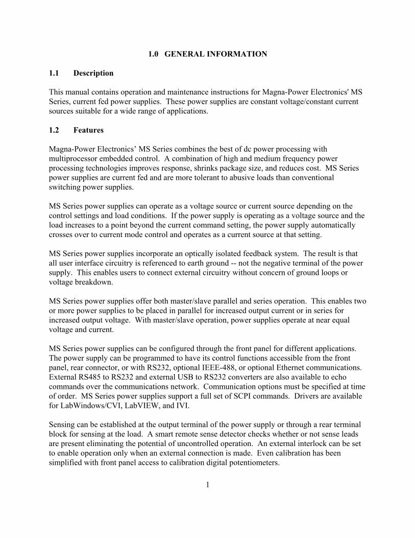
This manual contains operation and maintenance instructions for Magna-Power Electronics' MSSeries, current fed power supplies. These power supplies are constant voltage/constant currentsources suitable for a wide range of applications.
1.2 Features
Magna-Power Electronics’ MS Series combines the best of dc power processing withmultiprocessor embedded control. A combination of high and medium frequency powerprocessing technologies improves response, shrinks package size, and reduces cost. MS Seriespower supplies are current fed and are more tolerant to abusive loads than conventionalswitching power supplies.
MS Series power supplies can operate as a voltage source or current source depending on thecontrol settings and load conditions. If the power supply is operating as a voltage source and theload increases to a point beyond the current command setting, the power supply automaticallycrosses over to current mode control and operates as a current source at that setting.
MS Series power supplies incorporate an optically isolated feedback system. The result is thatall user interface circuitry is referenced to earth ground -- not the negative terminal of the powersupply. This enables users to connect external circuitry without concern of ground loops orvoltage breakdown.
MS Series power supplies offer both master/slave parallel and series operation. This enables twoor more power supplies to be placed in parallel for increased output current or in series forincreased output voltage. With master/slave operation, power supplies operate at near equalvoltage and current.
MS Series power supplies can be configured through the front panel for different applications. The power supply can be programmed to have its control functions accessible from the frontpanel, rear connector, or with RS232, optional IEEE-488, or optional Ethernet communications. External RS485 to RS232 and external USB to RS232 converters are also available to echocommands over the communications network. Communication options must be specified at timeof order. MS Series power supplies support a full set of SCPI commands. Drivers are availablefor LabWindows/CVI, LabVIEW, and IVI.
Sensing can be established at the output terminal of the power supply or through a rear terminalblock for sensing at the load. A smart remote sense detector checks whether or not sense leadsare present eliminating the potential of uncontrolled operation. An external interlock can be setto enable operation only when an external connection is made. Even calibration has beensimplified with front panel access to calibration digital potentiometers.
1

MS Series power supplies have three levels of over voltage/current protection: shutdown ofcontrolling insulated gate bipolar transistors (IGBT’s), disconnect of main power, and inputfuses. After an over voltage/current trip condition, the supply must be reset.
MS Series power supplies have push button start/stop controls. These controls are tied to amechanical contactor which operates with the electronic switches to break the ac mains whenstop is commanded. Unlike competing products, an off means both an electrical and mechanicalbreak in the power circuit — not a break in an electronic switch. Safety comes first at Magna-Power Electronics.
MS Series power supplies are available with three alternative front panels: A Version for analogcontrol, D Version for digital control, and C Version for computer or programmable logiccontrol. All MS Series power supplies employ the same power processing engine. Table 1.1shows a comparison between the different models.
MS Series models utilizing the A Version front panel, MSA, provide stepless analog controlfrom front panel potentiometers. With simple configuration changes, voltage, current, overvoltage trip, and over current trip may be programmed from the rear connector or with RS232,optional IEEE-488, or optional Ethernet communications. MSA Series power supplies are wellsuited for industrial applications requiring a minimum of control.
MS Series models utilizing the D Version front panel, MSD, provide all of the features of the AVersion plus these models can be configured for keypad entries and up/down presses for voltage,current, over voltage trip, and over current trip. Key strokes are kept to a minimum by a repeatlast command feature. MSD Series power supplies are well suited for laboratory applicationsrequiring enhanced control.
MSD Series models have one-hundred memory states available to program voltage, current, overvoltage trip, over current trip, and time period. Set points can be auto sequenced with time orexternal triggering. Special programming codes allow repeating to create a power functiongenerator. The first 10 memory states are displayed on the front panel to simplify programmingtasks.
MSD Series power supplies offer an analog input to modulate the voltage or current setting usingpiecewise linear approximation. This feature enables the voltage or current setting to be adjustedby a sensor input, such as a thermistor, or by monitoring its own voltage or current. Modulationallows the output to be tailored for advanced process control applications, battery charging, andsource emulation.
MS Series models utilizing the C Version front panel, MSC, only allow control from the rearconnector or with RS232, optional IEEE-488, or optional Ethernet communications. These
2

Table 1.1 COMPARISON CHART OF FRONT AND REARPANEL CONTROLS AND INDICATORS
FeaturesMODELS
MSC MSA MSD
FRONT PANEL CONTROLSPower on/offStart/StopRotary voltage/current entryRotary OVT/OCT entryMenu/ItemDisplay settingsEnter/ClearKeypad voltage/current entryKeypad OVT/OCT entryArm
INDICATORSVoltage/current set pointOVT/OCT set pointVoltage/current outputInternal/external controlAlarmsRotary/external/remote programmingRemote sense enabledKeypad programmingMemory settingArmed for auto sequence operation
REAR PANEL CONTROLSVoltage/current set pointOVT/OCT set pointModulation set pointVoltage/current outputInternal/external controlAlarm outputs (9 lines)Status outputs (6 lines)Master/Slave connectionsRemote sense inputsRS232 inputs/outputsOptional IEEE-488 inputs/outputsOptional Ethernet inputs/outputsInterlock enableArm enable
!
!!
!!!!!!!!!!
!!!!!!!
!!!!!!!
!!
!!!!!!!!!!
!!!
!!!!!!
!!!!!!!!!!
!!!!!!!!!!!!!!
3

models are intended for process control applications where front panel controls and displays arenot required or desired.
Remote Interface Software is included to provide sophisticated computer control. This softwareprovides a virtual control panel to emulate the power supply’s front panel, a command panel tosend and monitor SCPI commands, a register panel to monitor registers, a calibration panel toprovide easy access to calibrate digital potentiometers, a firmware panel to upgrade the controlmicroprocessor, and a modulation panel to easily program modulation parameters.
MS Series models have extensive diagnostic functions -- all of which when activated takecommand to shut down the system. Diagnostic functions include phase loss, excessive thermalconditions, over voltage trip, over current trip, fuse clearing, and program line. Program linemonitors externally applied analog set point signals to insure they are within the specified range. Upon a diagnostic fault condition, main power is disconnected and the diagnostic condition islatched into memory. Pressing the clear key clears the memory. All diagnostic functions can bemonitored through a rear connector. Furthermore, control functions can also be set through therear connector to allow simultaneous control of one or more MS Series units.
1.3 IEC Symbols Used in Manual
The following IEC symbols are used in this manual.
Caution, risk of electric shock
Caution, risk of danger
Protective conductor terminal
Three-phase alternating current
1.4 Power Requirements
MS power supplies are manufactured to operate on 208/240 V, 380/415 V, or 440/480 V 50 to60 Hz mains.
The standard operating voltage is 208 V, 3φ, 50 to 60 Hz unless otherwise specified at time oforder. For conversion from 208 V to 240 V operation, two internal wiring changes must bemade to each power module. The locations are not accessible to the user and the power supplymust be returned to the factory for modification.
4
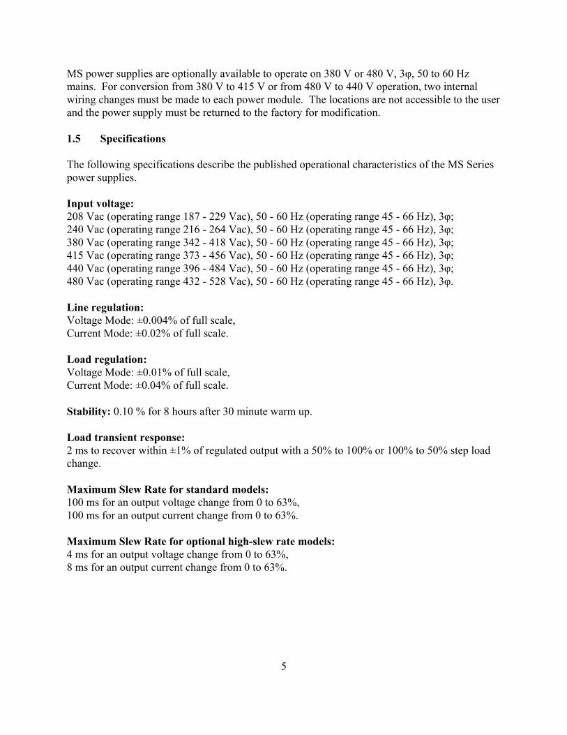
MS power supplies are optionally available to operate on 380 V or 480 V, 3φ, 50 to 60 Hzmains. For conversion from 380 V to 415 V or from 480 V to 440 V operation, two internalwiring changes must be made to each power module. The locations are not accessible to the userand the power supply must be returned to the factory for modification.
1.5 Specifications
The following specifications describe the published operational characteristics of the MS Seriespower supplies.
Input voltage:208 Vac (operating range 187 - 229 Vac), 50 - 60 Hz (operating range 45 - 66 Hz), 3φ; 240 Vac (operating range 216 - 264 Vac), 50 - 60 Hz (operating range 45 - 66 Hz), 3φ; 380 Vac (operating range 342 - 418 Vac), 50 - 60 Hz (operating range 45 - 66 Hz), 3φ; 415 Vac (operating range 373 - 456 Vac), 50 - 60 Hz (operating range 45 - 66 Hz), 3φ; 440 Vac (operating range 396 - 484 Vac), 50 - 60 Hz (operating range 45 - 66 Hz), 3φ; 480 Vac (operating range 432 - 528 Vac), 50 - 60 Hz (operating range 45 - 66 Hz), 3φ.
Line regulation:Voltage Mode: ±0.004% of full scale,Current Mode: ±0.02% of full scale.
Load regulation:Voltage Mode: ±0.01% of full scale,Current Mode: ±0.04% of full scale.
Stability: 0.10 % for 8 hours after 30 minute warm up.
Load transient response:2 ms to recover within ±1% of regulated output with a 50% to 100% or 100% to 50% step loadchange.
Maximum Slew Rate for standard models:100 ms for an output voltage change from 0 to 63%,100 ms for an output current change from 0 to 63%.
Maximum Slew Rate for optional high-slew rate models:4 ms for an output voltage change from 0 to 63%,8 ms for an output current change from 0 to 63%.
5

Bandwidth for standard models:3 Hz with remote analog voltage programming,2 Hz with remote analog current programming.
Bandwidth for optional high-slew rate models:60 Hz with remote analog voltage programming,45 Hz with remote analog current programming.
Efficiency: greater than 86%, see Model and Ratings tables for details.
Temperature coefficient: 0.04 %/EC of maximum output voltage, 0.06 %/EC of maximum output current.
Isolation:User inputs and outputs: referenced to earth ground,Maximum input voltage to ground: ±2500 Vac,Maximum output voltage to ground:
±1000 Vdc for models less than or equal to 1000 Vdc,±(2000 Vdc + VO/2) for models greater than 1000 Vdc or with High Output IsolationOption (+ISO) where VO is the output voltage of the power supply.
Power Factor: greater than 92% at maximum power.
Ambient Temperature: 0 to 50EC.
Water Cooling:Inlet temperature: 25°C maximum,Flow rate:
3.0 GPM minimum for 30 kW units,4.5 GPM minimum for 45-75 kW units.
Pressure: 80 PSI maximum,Pipe size: 1/2" NPT male.
Storage Temperature: -25 to +85EC.
Remote sense limits: 3% maximum voltage drop from output terminals to load. Remote senseis not available for models with output voltages greater than 1000 Vdc or with +ISO option.
Remote analog programming limits:Voltage set point: 0 to 10.0 Vdc for 0 to 100% output,Current set point: 0 to 10.0 Vdc for 0 to 100% output,Over voltage trip set point: 0 to 10.0 Vdc for 0 to 110% output,Over current trip set point: 0 to 10.0 Vdc for 0 to 110% output,
6

Modulation: 0 to 10 Vdc (D Version models only).
Remote analog input impedance: 10K for all inputs.
Remote analog programming accuracy of full scale:Voltage set point: ±0.1%,Current set point: ±0.1%,Over voltage trip set point: ±0.1%,Over current trip set point: ±0.1%.
Analog monitoring and reference:Output voltage: 0 to 10.0 Vdc, 5 mA, Output current: 0 to 10.0 Vdc, 5 mA,+10V Ref: 10.0 Vdc, 5 mA,
Analog output impedances:Voltage output monitoring: 100 ohm, Current output monitoring: 100 ohm,+10V Ref: 1 ohm.
Analog monitoring accuracy of full scale:Output voltage: ±0.2%,Output current: ±0.2%,+10V Ref: ±.50%.
Digital programming accuracy of full scale:Voltage set point: ±0.1%,Current set point: ±0.1%,Over voltage trip set point: ±0.1%,Over current trip set point: ±0.1%.
Digital readback accuracy of full scale:Output voltage: ±0.2%,Output current: ±0.2%.
Period programming limits:Minimum period: 10 msec,Maximum period: 9997 sec or 2.77 hours.
Digital control inputs and outputs limits:Input voltage: 0 to 5 Vdc, 10K input impedance;Output voltages: 0 to 5 Vdc, 5 mA drive capacity per line;5 V supply: 25 mA.
7

User interface connectors, see figure 1.1 and Tables 1.5, 1.6, 1.7, 1.8, and 1.9 for details:JS1: 37 pin D-Subminiature, female;JS2: 2 terminal 6-32 screw connector;JS3: 9 pin D-Subminiature, female.JS4: optional 24 pin IEEE-488, female.JS5: optional 8 pin RJ45, female.
RS232 interface:Baud Rate: 19200 Baud,Data Size: 8-bit,Parity: None,Stop bits: 1.
Optional Ethernet Interface:IP address: 169.254.x.xSubnet Mask: 255.255.0.0Default Getaway: 0.0.0.0DNS Server: 0.0.0.0
Size and Weight: see figure 1.2, figure 1.3, and Table 1.4 for details.
Agency Approvals:CE-marked units meet the following standards:
EN61010-1:2001-02 Safety Requirements for Electrical Equipment forMeasurement, Control, and Laboratory Use
89/336/EEC EMC DirectiveEN61000-6-3:2001 General Emissions StandardEN55022 Class A Product Specifications Emissions
EN61326-1:1997 and EN61000-6-2:2001 Generic Immunity Standard• EN61000-4-2 Electrostatic Discharge• EN61000-4-3 Radiated Susceptibility • EN61000-4-6 Conducted Susceptibility
Optional Ethernet Interface units meet the following standards
LXI Class C, Revision 1.2
8
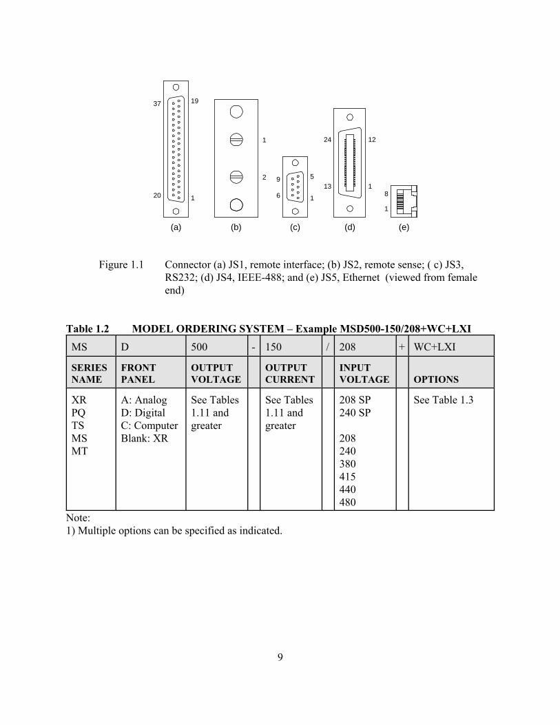
Figure 1.1 Connector (a) JS1, remote interface; (b) JS2, remote sense; ( c) JS3,RS232; (d) JS4, IEEE-488; and (e) JS5, Ethernet (viewed from femaleend)
Table 1.2 MODEL ORDERING SYSTEM – Example MSD500-150/208+WC+LXI
MS D 500 - 150 / 208 + WC+LXI
SERIESNAME
FRONTPANEL
OUTPUTVOLTAGE
OUTPUTCURRENT
INPUTVOLTAGE OPTIONS
XRPQTSMSMT
A: AnalogD: DigitalC: ComputerBlank: XR
See Tables1.11 andgreater
See Tables1.11 andgreater
208 SP240 SP
208240380415440480
See Table 1.3
Note:1) Multiple options can be specified as indicated.
37 19
120
5
1
9
6
(c)(a)
24 12
113
(d) (e)
1
8
1
2
(b)
9

Table 1.3 OPTIONS
TERM DEFINITION
WCHSLXIGPIBUSBRS485ISOEW
Water CoolingHigh-Slew RateLXI TCP/IP Ethernet Interface (Internal)IEEE488.2 GPIB Interface (Internal)USB Interface (External)RS485 Interface (External)High Output IsolationExtended Warranty
Table 1.4 SIZE AND WEIGHT MATRIX
POWERkW
SIZEH”xW”xD”
WEIGHTLBS
30456075
38.5 x 22 x 29 in (97.8 x 55.9 x 73.7 cm)38.5 x 22 x 29 in (97.8 x 55.9 x 73.7 cm)38.5 x 22 x 29 in (97.8 x 55.9 x 73.7 cm)49 x 22 x 29 in (124.46 x 55.9 x 73.7 cm)
280 lbs (127.0 kg)395 lbs (179.2 kg)510 lbs (231.3 kg)645 lbs (292.6 kg)
Table 1.5 TERMINAL DEFINITIONS FOR CONNECTOR JS1, REMOTEINTERFACE
TERM PARAMETER TERM PARAMETER TERM PARAMETER
123456789
10111213
REF GNDREF GNDVREF EXTTVREF EXTVO2+2.5V REF CALGNDPOWERTHERMALINTERLOCKCUR CTLSTANDBY/ALMALM
14151617181920212223242526
EXT CTLFUSERESERVESTARTCLEARSTOPREF GND+10V REFIREF EXTTIREF EXTIO2VMOD+5V
2728293031323334353637
PGM LINESTANDBYPHASE LOSSVOLT CTLRESERVEOCTINT CTLOVTRESERVEARMINTERLOCKSET
10
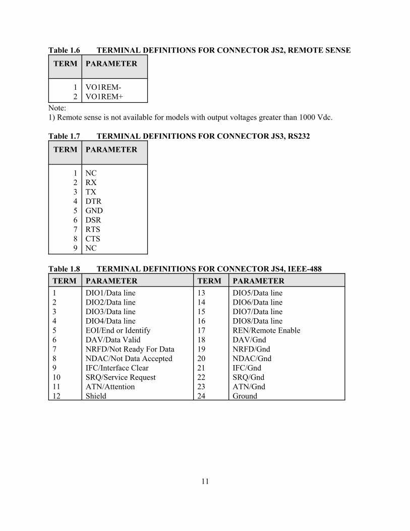
Table 1.6 TERMINAL DEFINITIONS FOR CONNECTOR JS2, REMOTE SENSE
TERM PARAMETER
12
VO1REM-VO1REM+
Note:1) Remote sense is not available for models with output voltages greater than 1000 Vdc.
Table 1.7 TERMINAL DEFINITIONS FOR CONNECTOR JS3, RS232
TERM PARAMETER
123456789
NCRXTXDTRGNDDSRRTSCTSNC
Table 1.8 TERMINAL DEFINITIONS FOR CONNECTOR JS4, IEEE-488
TERM PARAMETER TERM PARAMETER
123456789101112
DIO1/Data lineDIO2/Data lineDIO3/Data lineDIO4/Data lineEOI/End or IdentifyDAV/Data ValidNRFD/Not Ready For DataNDAC/Not Data AcceptedIFC/Interface ClearSRQ/Service RequestATN/AttentionShield
131415161718192021222324
DIO5/Data lineDIO6/Data lineDIO7/Data lineDIO8/Data lineREN/Remote EnableDAV/GndNRFD/GndNDAC/GndIFC/GndSRQ/GndATN/GndGround
11

Table 1.9 TERMINAL DEFINITIONS FOR CONNECTOR JS5, ETHERNET
TERM PARAMETER
12345678
TX+TX-RX+NCNCRX-NCNC
Table 1.10 OPTIONAL HIGH-SLEW OUTPUT PARAMETERS (30 KW MODELS)
OUTPUTVOLTAGERANGEVdc
OUTPUTPOWERRANGEkW
OUTPUTCAPACITANCE
μFRIPPLE
Vrms
5810-16203240-80100-250375-40050060080010001500-20003000-4000
5 - 15
26400180008160468023406004003201401401121043618
.50
.50
.50
.701.41.51.61.82.12.32.53.03.54.0
Note:1) For 45 kW models, multiply capacitance and current by 1.5, 2) For 60 kW models, multiply capacitance and current by 2,3) For 75 kW models, multiply capacitance and current by 2.5.
12

Table 1.11 30 KW MODELS AND RATINGS
MODELVOLTS
VdcAMPS
AdcRIPPLEmVrms
EFF
%
INPUT CURRENT (Aac)
208/240 V 380/415 V 440/480 V
MSA16-1800MSA20-1500MSA32-900MSA40-750MSA50-600MSA80-372MSA100-300MSA125-240MSA160-186MSA200-150MSA250-120MSA375-78MSA400-72MSA500-60MSA600-48MSA800-36MSA1000-30MSA1500-19.8MSA2000-15.0MTSA3000-9.6MSA4000-7.2
162032405080
100125160200250375400500600800
10001500200030004000
18001500900750600372300240186150120787260483630
19.815.09.67.2
35404040506060
100120125130170200220250300350400450500550
868686878787878787878888888888888888888888
108108108108108108106106106106106106106106106106106106106106106
606060606060585858585858585858585858585858
545454545454525252525252525252525252525252
Notes:1) Rating specified at 208, 380, and 440 V input.2) Specifications subject to change without notice.3) MSA, MSD, and MSC models all have identical ratings.
13

Table 1.12 45 KW MODELS AND RATINGS
MODELVOLTS
VdcAMPS
AdcRIPPLEmVrms
EFF
%
INPUT CURRENT (Aac)
208/240 V 380/415 V 440/480 V
MSA16-2700MSA20-2250MSA32-1350MSA40-1125MSA50-900MSA80-558MSA100-450MSA125-360MSA160-279MSA200-225MSA250-180MSA375-117MSA400-108MSA500-90MSA600-72MSA800-54MSA1000-45MSA1500-27.7MSA2000-22.5MSA3000-14.4MSA4000-10.8
162032405080
100125160200250375400500600800
10001500200030004000
270022501350112590055845036027922518011710890725445
27.722.514.410.8
35404040506060
100120125130170200220250300350400450500550
868686878787878787878888888888888888888888
162162162162162162159159159159159159159159159159159159159159159
909090909090878787878787878787878787878787
818181818181787878787878787878787878787878
Notes:1) Rating specified at 208, 380, and 440 V input.2) Specifications subject to change without notice.3) MSA, MSD, and MSC models all have identical ratings.
14
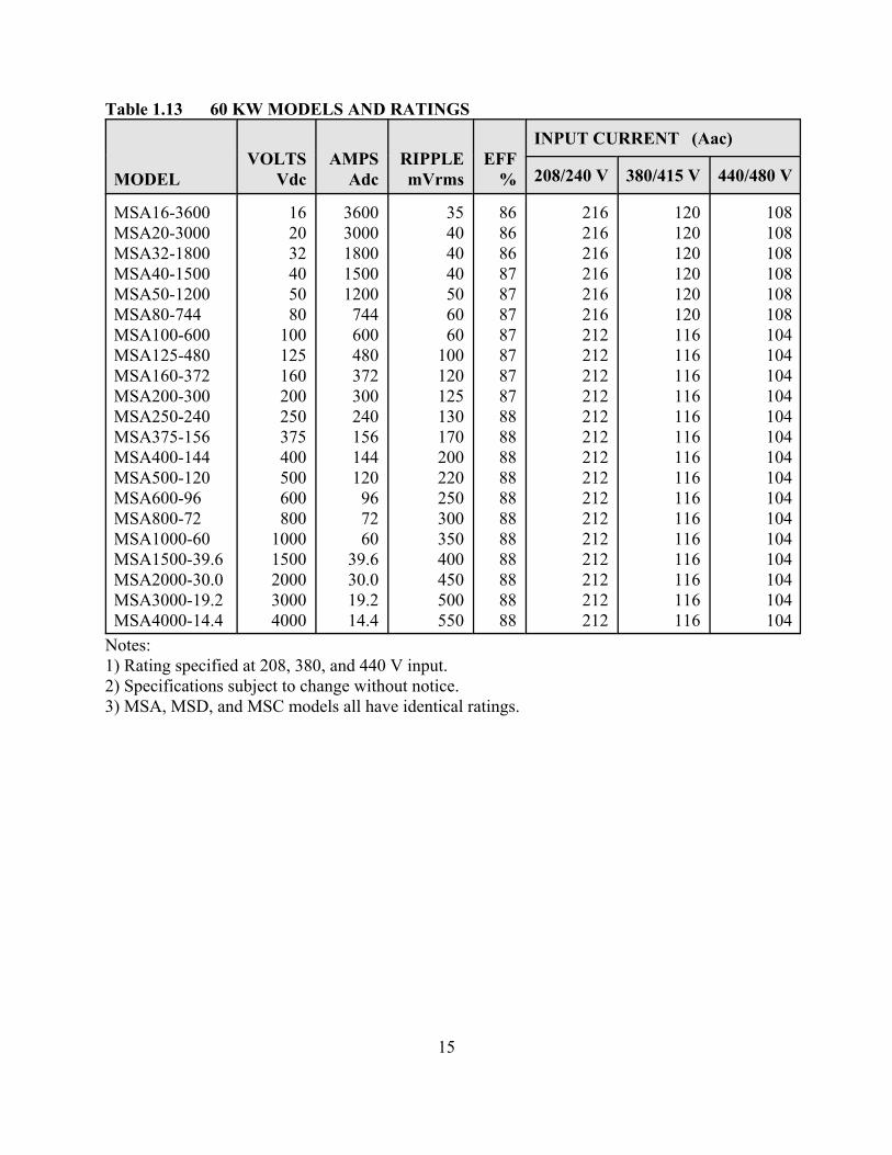
Table 1.13 60 KW MODELS AND RATINGS
MODELVOLTS
VdcAMPS
AdcRIPPLEmVrms
EFF
%
INPUT CURRENT (Aac)
208/240 V 380/415 V 440/480 V
MSA16-3600MSA20-3000MSA32-1800MSA40-1500MSA50-1200MSA80-744MSA100-600MSA125-480MSA160-372MSA200-300MSA250-240MSA375-156MSA400-144MSA500-120MSA600-96MSA800-72MSA1000-60MSA1500-39.6MSA2000-30.0MSA3000-19.2MSA4000-14.4
162032405080
100125160200250375400500600800
10001500200030004000
36003000180015001200744600480372300240156144120967260
39.630.019.214.4
35404040506060
100120125130170200220250300350 400450500550
868686878787878787878888888888888888888888
216216216216216216212212212212212212212212212212212212212212212
120120120120120120116116116116116116116116116116116116116116116
108108108108108108104104104104104104104104104104104104104104104
Notes:1) Rating specified at 208, 380, and 440 V input.2) Specifications subject to change without notice.3) MSA, MSD, and MSC models all have identical ratings.
15

Table 1.14 75 KW MODELS AND RATINGS
MODELVOLTS
VdcAMPS
AdcRIPPLEmVrms
EFF
%
INPUT CURRENT (Aac)
208/240 V 380/415 V 440/480 V
MSA16-4500MSA20-3750MSA32-2250MSA40-1875MSA50-1500MSA80-930MSA100-750MSA125-600MSA160-465MSA200-375MSA250-300MSA375-195MSA400-180MSA500-150MSA600-120MSA800-90MSA1000-75MSA1500-49.5MSA2000-37.5MSA3000-24.0MSA4000-18.0
162032405080
100125160200250375400500600800
10001500200030004000
450037502250187515009307506004653753001951801501209075
49.537.524.018.0
35404040506060
100120125130170200220250300350400450500550
868686878787878787878888888888888888888888
270270270270270270265265265265265265265265265265265265265265265
150150150150150150145145145145145145145145145145145145145145145
135135135135135135130130130130130130130130130130130130130130130
Notes:1) Rating specified at 208, 380, and 440 V input.2) Specifications subject to change without notice.3) MSA, MSD, and MSC models all have identical ratings.
16

Figure 1.2 MS Series air cooled package drawing with D Version front panel
FRONT REAR
INPUTPOWERCONNECTIONS
22.000
MASTERCONTROL
PANEL
1.125
49.125 FOR 75 KW MODELS38.625 FOR 30-60 KW MODELS
EX T C TL
IN T C T L
R OT AR Y
KEYPAD
A RM
MEM
ME NU9
IT EM6
3
87
5
2
4
1
R EM OT E
C L EAREN TER
ELECTRONICS
0
MAGNA-POWER
EX T P G M
SE
TP
OIN
T
MEM
3A RMF SE
C T L
O CTT H L O VT
DCCURRENT
600
DCVOLTAGE
PH L
C T L
L O C P G L
START36.0
VOLTAGE
STOP
IO PWRCURRENT
D ISP L AY
SE
TUP
MO
DE
ST A ND BY
R EM SEN
POW ER
AIRINTAKE
5.125
5.000
.406 DIA. THRU, 4 PLC'S
REAR PANEL
0.250
BUSOUTPUT
JS1JS3
JS1JS3
JS5 JS4
IEEE-488INTERFACE
ETHERNETINTERFACE
DETAIL OF OPTIONAL INTERFACES
R ST
LA N .281 DIA. THRU
REAR PANEL
0.750
3.250
HIGH VOLTAGE UNITSDETAILS OF OUTPUT BUSDETAILS OF OUTPUT BUS
LOW/MEDIUM VOLTAGE UNITS
AIR EXHAUST FANS
JS2
1
2
JS1JS3
INLETWATER
OUTLETWATER
2.250
0.250
17

Figure 1.3 MS Series water cooled package drawing with D Version front panel
FRONT REAR
INPUTPOWERCONNECTIONS
22.000
MASTERCONTROL
PANEL
1.125
49.125 FOR 75 KW MODELS38.625 FOR 30-60 KW MODELS
EXT CTL
INT CTL
RO T ARY
KEYPA D
ARM
MEM
M ENU9
IT EM6
3
87
5
2
4
1
REM O TE
C LEARENTER
ELECTRONICS
0
M AGN A-P OW ER
EXT PG M
SET
POI
NT
M EM
3A RMFSE
CTL
O CTTHL OV T
DC CURR E N T
600D C VO L T A G E
PHL
C TL
L OC PGL
START36.0
VOLTAGE
STOP
IO PWRCURRENT
DI SPLAY
SET
UPM
ODE
ST ANDBY
REM SE N
POW ER
JS2
1
2
JS1JS3
JS1JS3
JS5 JS4
IEEE-488INTERFACE
ETHERNETINTERFACE
JS1JS3
DETAIL OF OPTIONAL INTERFACES
R ST
LAN
INLETWATER
OU TLETWATER
5.125
5.000
.406 DIA. THRU, 4 PLC'S
REAR PANEL
0.250
BUSOUTPUT
.281 DIA. THRU
REAR PANEL
0.750
3.250
HIGH VOLTAGE UNITSDETAILS OF OUTPUT BUSDETAILS OF OUTPUT BUS
LOW/MEDIUM VOLTAGE UNITS
2.250
0.250
18
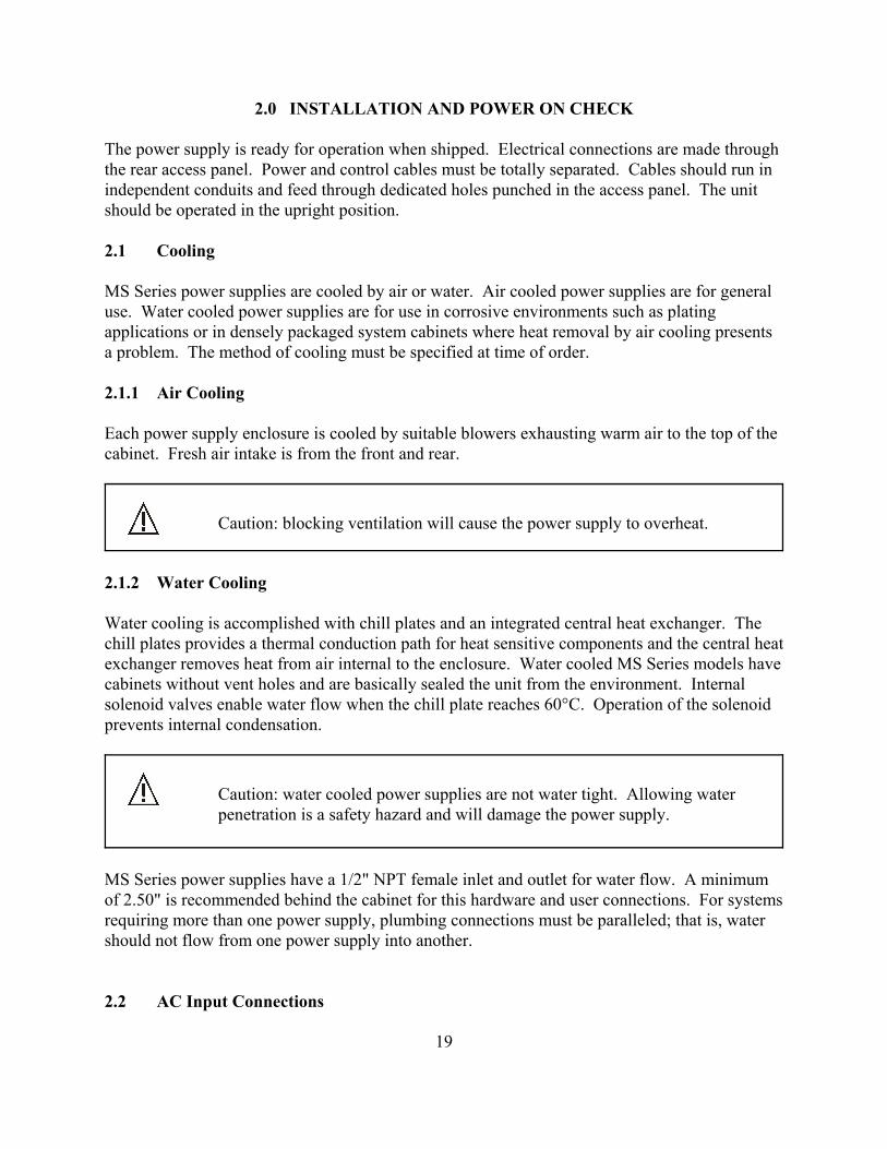
2.0 INSTALLATION AND POWER ON CHECK
The power supply is ready for operation when shipped. Electrical connections are made throughthe rear access panel. Power and control cables must be totally separated. Cables should run inindependent conduits and feed through dedicated holes punched in the access panel. The unitshould be operated in the upright position.
2.1 Cooling
MS Series power supplies are cooled by air or water. Air cooled power supplies are for generaluse. Water cooled power supplies are for use in corrosive environments such as platingapplications or in densely packaged system cabinets where heat removal by air cooling presentsa problem. The method of cooling must be specified at time of order.
2.1.1 Air Cooling
Each power supply enclosure is cooled by suitable blowers exhausting warm air to the top of thecabinet. Fresh air intake is from the front and rear.
Caution: blocking ventilation will cause the power supply to overheat.
2.1.2 Water Cooling
Water cooling is accomplished with chill plates and an integrated central heat exchanger. Thechill plates provides a thermal conduction path for heat sensitive components and the central heatexchanger removes heat from air internal to the enclosure. Water cooled MS Series models havecabinets without vent holes and are basically sealed the unit from the environment. Internalsolenoid valves enable water flow when the chill plate reaches 60°C. Operation of the solenoidprevents internal condensation.
Caution: water cooled power supplies are not water tight. Allowing waterpenetration is a safety hazard and will damage the power supply.
MS Series power supplies have a 1/2" NPT female inlet and outlet for water flow. A minimumof 2.50" is recommended behind the cabinet for this hardware and user connections. For systemsrequiring more than one power supply, plumbing connections must be paralleled; that is, watershould not flow from one power supply into another.
2.2 AC Input Connections
19

Caution: disconnect AC power from the mains before attempting anyinstallation procedure.
Caution: a safety ground wire must be connected to the unit as indicated bythe protective ground symbol at the rear of the power supply.
AC power is wired to the power supply by attaching three cables plus ground. The manufacturerecommends cables, as specified in Tables 2.1 or 2.2, be crimped to ring terminals and securelyfastened to the four studs at the rear of the power supply.
This power supply is designed to be permanently connected to the power source requiring areadily accessible disconnect device incorporated into the fixed wiring.
2.3 DC Output Connections
Caution: disconnect AC power from the mains before attempting anyinstallation procedure.
Table 2.1 SUGGESTED AMPACITIES OF 4-CONDUCTORTYPE S OR SO CABLE
Wire Size(AWG)
MaximumCurrent
(A)Wire Size
(AWG)
MaximumCurrent
(A)
1816141210
710152025
8642
35456080
20

Table 2.2 SUGGESTED AMPACITIES OF CONDUCTORS AS RECOMMENDED BY THE NATIONAL ELECTRICAL CODE
Temperature Rating of Copper Conductor
60 °C 75°C 85°C 90°C
Types Types Types Types
Wire Size(AWG)
RUW, T, TW FEPW, RH,RHW, RUH,
THW, THWN,XHHW, ZW
V, MI TA, TBS, SA, AVB,SIS, FEP, FEPB,
RHH, THHN, XHHW
141210864321
1/02/03/04/0
250 MCM300 MCM350 MCM
2530406080
105120140165195225260300340375420
3035507095
125145170195230265310360405445505
30405575
100135160185215250290335390440485550
35405580
105140165190220260300350405455505570
Single conductors in free air, based on ambient temperature of 30°C
DC power is wired to the power supply by attaching two cables to the output bus bars. Themanufacture recommends cables, as specified in Tables 2.2 or 2.3, be crimped to ring terminalsand securely fastened to bus bars using 3/8" bolts, lock washers, and mating nuts. Afterconnections are made, place the protective cover over the output bus bars.
Caution: Make sure connections are tight to avoid overheating of the bus bars.
21

Table 2.3 SUGGESTED AMPACITIES OF WELDING CABLE
Wire Size(AWG)
MaximumCurrent
(A)Wire Size
(AWG)
MaximumCurrent
(A)
64321
85110130150170
1/02/03/04/0
*
200235275315
315+
* Contact factory for assistance
2.4 General Operation
As shipped, MSA and MSD Series power supplies are configured for local sensing, rotarycontrol, internal programming, and voltage input as specified on the rear label. MSC Seriespower supplies are configured for RS232, optional IEEE-488, or optional Ethernetcommunications. The front panel voltage and current controls set the boundary limits for outputvoltage and current, respectively. The impedance of the load determines whether the unit isvoltage or current controlled and the illumination of the respective mode indicator light indicatesthe state. If either control is set to maximum counter clockwise rotation, the other control willhave little or no effect. Each control must be set to the appropriate position for proper operation.
2.5 Controls and Indicators
The controls and indicators MSD, MSA, MSC Series power supplies are illustrated in figures2.1, 2.2, and 2.3 respectively.
2.6 Preparation for Use
2.6.1 Unpacking
Carefully unpack the power supply saving all packing materials and included enclosures. Inspect power supply for possible shipping damage. Check that there are no broken knobs orconnectors, the external surface is not scratched or dented, the meter faces are not damaged, andall controls move freely. Any external damage may be an indication of internal damage.
2.6.2 Electrical Check
2.6.2.1 MSD Series Models
With the power supply off, disconnect the load, set voltage and current potentiometer controlsfull counterclockwise, and set the over voltage trip and over current settings to maximum. Connect the power supply to a suitable source of ac voltage. (For this test, only 50% of rated ac
22

current is required.) Turn the power switch on and observe the indicator lights going through thestartup routine. After initialization, the following indicator lights should be on: standby, int ctl,ext ctl, and rotary. This is the default configuration from the factory. It is recommended that thefollowing brief electrical check be made shortly after unpacking the supply.
Press the start switch and advance the current control one turn clockwise. The power andvoltage control indicators should light. Increase the voltage set point to maximum and then tominimum. Dc voltage should increase smoothly from minimum to maximum to minimum asindicated on the meter. Return the voltage control full counterclockwise. Press the stop switch.
To check over voltage trip, press the menu key and the item key two times. This places thepower supply in data entry mode to set over voltage trip. Using the keypad, enter an overvoltage trip set point at half the rating of the power supply. Once the over voltage trip set pointhas been entered, press the enter key to save the information.
Press the start switch and slowly increase the voltage set point. Over voltage trip should operateat the over voltage trip set point. The over voltage trip (OVT) indicator should turn on, thepower and voltage control indicators should turn off, and the supply should shut down. Pressthe clear key. Now set the over voltage trip set point to maximum which is 110% the full scalerating of the power supply. Because the over voltage trip set point was the last keypadcommand, data can simply be entered, eliminating the key presses of menu and item. With themaximum over voltage trip set point entered, again start the supply and observe that the powersupply operates normally. With the main power disconnected, connect a short to the power output studs on the rear panel. Reconnect the main power, set voltage and current controls full counterclockwise and turn thepower switch on.
Press the start switch and advance the voltage control one turn clockwise. Increase the currentset point to maximum and then to minimum. The power and current control indicators shouldlight. Dc current should increase smoothly from minimum to maximum to minimum asindicated on the meter. Return the current control full counterclockwise. Press the stop switch.
To check over current trip, press the menu key and the item key three times. This places thepower supply in data entry mode to set over current trip. Using the keypad, enter an over currenttrip set point at half the rating of the power supply. Once the over current trip setting has beenentered, press the enter key to save the information.
Press the start switch and slowly increase the current set point. Over current trip should operateat the over current trip set point. The over current trip (OCT) indicator should turn on, the powerand current control indicators should turn off, and the supply should shut down. Press the clearkey. Now set the over current trip set point to maximum which is 110% the full scale rating ofthe power supply. Because the over current trip set point was the last keypad command, data cansimply be entered, eliminating the key presses of menu and item. With the maximum overcurrent trip set point entered, again start the supply and observe that the power supply operates
23

normally.
If any of these events do not occur, the supply is defective and should not be operated. Depending on the circumstances, either warranty service or trouble shooting, as described inSection 7.2, is required.
2.6.2.2 MSA Series Models
With the power supply off, disconnect the load, set voltage and current potentiometer controlsfull counterclockwise, and set the over voltage trip and over current trip potentiometer controlsfull clockwise. Connect the power supply to a suitable source of ac voltage. (For this test, only50% of rated ac current is required.) Turn the power switch on and observe the indicator lightsgoing through the startup routine. After initialization, the following indicator lights should beon: standby, int ctl, ext ctl, and rotary. This is the default configuration from the factory. It isrecommended that the following brief electrical check be made shortly after unpacking thesupply.
Press the start switch and advance the current control one turn clockwise. The power andvoltage control indicators should light. Increase the voltage set point to maximum and then tominimum. Dc voltage should increase smoothly from minimum to maximum to minimum asindicated on the meter. Return the voltage control full counterclockwise. Press the stop switch.
To check over voltage trip, press the trip dis key on the front panel and set the over voltage trippotentiometer to half the voltage rating of the supply. While the trip dis key is pressed, thevoltmeter and ammeter displays the over voltage trip and over current trip settings.
Press the start switch and slowly increase the voltage set point. Over voltage trip should operateat the over voltage trip set point. The over voltage trip (OVT) indicator should turn on, thepower and voltage control indicators should turn off, and the supply should shut down. Pressthe clear key. Now set the over voltage trip set point to maximum which is 110% the full scalerating of the power supply. Again start the supply and observe that the power supply operatesnormally.
With the main power disconnected, connect a short to the power output studs on the rear panel. Reconnect the main power, set voltage and current controls full counterclockwise, set the overvoltage trip and over current trip potentiometer controls full clockwise, and turn the powerswitch on.
Press the start switch and advance the voltage control one turn clockwise. Increase the currentset point to maximum and then to minimum. The power and current control indicators shouldlight. Dc current should increase smoothly from minimum to maximum to minimum asindicated on the meter. Return the current control full counterclockwise. Press the stop switch.
To check over current trip, press the trip dis key on the front panel and set the over current trippotentiometer to half the current rating of the supply. While the trip dis key is pressed, the
24

voltmeter and ammeter displays the over voltage trip and over current trip settings.
Press the start switch and slowly increase the current set point. Over current trip should operateat the over current trip set point. The over current trip (OCT) indicator should turn on, the powerand current control indicators should turn off, and the supply should shut down. Press the clearkey. Now set the over current trip set point to maximum which is 110% the full scale rating ofthe power supply. Again start the supply and observe that the power supply operates normally.
If any of these events do not occur, the supply is defective and should not be operated. Depending on the circumstances, either warranty service or trouble shooting, as described inSection 7.2, is required.
2.6.2.3 MSC Series Models
The electrical check for MSC Series models require use of the Remote Interface Softwaredescribed in Section 5.0. With the software installed and the power supply connected to thedesired communications interface, select A Version in the Configuration Setup Panel. Select theVirtual Control Panel in the View Menu to display the A Version front panel. Follow theprocedure outlined in Section 2.6.2.2 using the Virtual Control Panel.
25

DIAGNOSTICSLOC: interlockPGL: external input beyond limitsPHL: indicates a problem with input voltageTHL: indicates over-temperatureOVT: shows over voltage protection has trippedOCT: shows over current protection has trippedFSE: warns that a fuse has clearedARM: indicates power supply is ready for or operating in autosequencing
MODE AND CONFIGURATIONPOWER: indicates power outputSTANDBY: indicates control power onlyREM SEN: indicates remote senseINT CTL: front panel controls enabledEXT CTL: external controls enabledROTARY: potentiometer voltage/current controlKEYPAD: keypad voltage/current controlEXT PGM: external voltage/current controlREMOTE: RS232 control enabled
FUNCTION KEYSMENU: selects functionITEM: selects item within functionDISPLAY: displays voltage and current settingARM: arms power supply for auto sequencingthrough states stored in memoryMEM: sets memory CLEAR: clears setting or reset fault condition : up : down
Figure 2.1 MSD Series controls and indicators
Meters display voltage, current, over voltageprotection, over current protection, andmemory step
Enter data throughkeyboard
Sets voltage and currentoutput in rotary mode
Energizes control circuits withoutturning on main power
Switches main poweron and off
ELECTRONICSMAGNA-POWER
CTL CTL
EXT CTL
ROTARY
REMOTE
EXT PGM
KEYPAD
REM SEN
STANDBY
POWERDC VOLTAGE DC CURRENT
CLEAR
MEM
ARMITEM4
0
1
6
ENTER
3
MEM
3INT CTL
STOP
PHLPGL OVTTHL OCTLOC
VOLTAGE CURRENT
START
PWR
2
5
7 8 9 DISPLAYMENU
FSE ARM
O I
16.0 600
26

DC VOLTAGE
START16.
CTL
0
OVT
600
CTL
DC CURRENT
PHASE
ENTER
MAGNA-POWERELECTRONICS
TRIP DISITEM
ROTARY
REMOTE
CLEAR
INT CTL
EXT CTL
OCT
MODE
POWER
STANDBY
V/I DISMENU
CONFIGURATION
EXT PGM
REM SEN
FUSE
OVT
OCT
THERM
ALARMS
PGM LN
LOCK
O ICURRENT
PWR
STOP
VOLTAGE
ALARMSLOCK: interlockPGM LN: external input beyond limitsOVT: shows over voltage protection has trippedOCT: shows over current protection has trippedFUSE: warns that a fuse has clearedTHERM: indicates over-temperaturePHASE: indicates a problem with input voltage
CONFIGURATIONINT CTL: front panel controls enabledEXT CTL: external controls enabledREM SEN: indicates remote senseEXT PGM: external voltage/current controlROTARY: potentiometer voltage/current controlREMOTE: RS232 control enabled
MODE POWER: indicates power outputSTANDBY: indicates control power only
Switches main poweron and off
FUNCTION KEYSMENU: selects functionITEM: selects item within functionV/I DIS: displays voltage and current settingTRIP DIS: displays OVT and OCT settingCLEAR: clears setting or reset fault conditionEnter: enter
Figure 2.2 MSA Series controls and indicators
Meters display output voltage, output current,voltage set point, current set point, overvoltage trip, and over current trip
Sets voltage and currentoutput
Sets over voltage trip andover current trip
Energizes control circuits withoutturning on main power
27

Figure 2.3 MSC Series controls and indicators
PWR MAGNA-POWERELECTRONICS
O I
Energizes control circuitswithout turning on mainpower
28

3.0 OPERATION
3.1 Front Panel Commands
As shipped, the MSA and MSD Series power supplies are configured for local sensing, rotarycontrol, internal programming, and voltage input as specified on the rear label. MSC Seriespower supplies cannot be controlled through the front panel other than on/off. The front panelvoltage and current controls set the boundary limits for output voltage and current, respectively. Section 2.6.2 describes how to start and operate the MS Series power supply using the defaultsettings. The following sections describe how to use all of the front panel features. Front panelcommands are broken into four groups: run mode commands, set point commands, configurationcommands, and calibration commands.
Run mode commands are used when the power supply has been configured for the desiredapplication and the desired set points have been programmed into memory.
Set point commands include voltage set, current set, over voltage trip set, over current trip set,and period set. All of these commands can be made when the power supply is in either thestandby, alarm, or power mode state.
Configuration commands include local or remote sense, internal and/or external control, remoteinterlock, and mode of set point input. There are four choices for set point inputs: rotary or frontpanel potentiometers, front panel keypad (MSD Series power supplies only), external analogthrough connector JS1, and RS232 communications through connector JS3, optional IEEE-488communications through connector JS4, and optional Ethernet communications through JS5. Changes in configuration commands are only allowed when the power supply is in the standbyor alarm state.
Calibration commands enable programming of internal digital potentiometers. The digitalpotentiometers are used for calibrating the voltage reference and feedback amplifiers. Calibration commands can be made when the power supply is in either the standby, alarm, orpower mode state.
Front panel programming commands are illustrated with programming charts. This method ofpresentation maps the path to key commands, describes front panel indicators as a result of keypresses, and illustrates anticipated results.
3.1.1 MSD Series Front Panel Commands
3.1.1.1 Run Mode Commands
Figure 3.1 illustrates run mode commands. Run mode commands are used when the powersupply has been configured for the desired application and the desired set points have beenprogrammed into memory.
29
MENU
START
STOP
ARM
CLEAR
MEM
STANDBY LED OFFPOWER LED ON
OUTPUT POWER ENABLED
OUTPUT POWER DISABLEDPOWER LED OFF
STANDBY LED ON
OUTPUT POWER DISABLED
PS PLACED IN ARMED STATE OR NON-ARMED STATEARM LED ON OR ARM LED OFF
ARM LED FLASHES WITH PS ARMEDPS STEPS THROUGH PROGRAM WITH PS ARMED
CLEARS ALL ALARMS LEDS EXCEPT FOR EXT TRIP
POWER LED OFF
STANDBY LED ON
DISPLAYS CUR SET ON CUR DISPLAYDISPLAYS VOLT SET ON VOLT DISPLAYDISPLAY
RETURNS TO NORMAL WHEN RELEASED
POWER LED OFF
PS RETURNS TO NORMAL OPERATION AT NEW MEMORY SETTING
MEMORY DISPLAY RETURNS TO PREVIOUS SETTING
MEMORY DISPLAY ENTERED AS MEMORY
MEMORY DISPLAY DECREMENTS
MEMORY DISPLAY INCREMENTS
MEMORY DISPLAYS NUMERIC KEY
CLEAR
ENTER
NUM KEYS
PS OPERATES AT MEMORY SETTING
PERIOD FLASHES IN MEMORY DISPLAY
PS RETURNS TO NORMAL OPERATION AT PREVIOUS MEMORY SETTING
PS OPERATES AT MEMORY SETTING
NUM KEYS SETPOINT DISPLAYS MOVES FROM RIGHT TO LEFT
SET POINT DISPLAY INCREMENTS
VOLT CTL, CUR CLT, OVT, OR OCT LED FLASHES
SET POINT DISPLAY DECREMENTS
NOTES:
1. SET POINT IS VOLT, CUR, OVT, OR OCT AS DEFINED BY LAST PROGRAMMED.
PS RETURNS TO NORMAL OPERATION
PS RETURNS TO NORMAL OPERATION
CLEAR SET POINT RETURNS TO PREVIOUS SETTING
DISPLAY ENTERED AS SET POINTENTER
VOLT CTL, CUR CLT, OVT, OR OCT LED FLASHES
VOLT CTL, CUR CLT, OVT, OR OCT LED FLASHES
ENTER DISPLAY ENTERED AS SET POINT
SET POINT RETURNS TO PREVIOUS SETTINGCLEAR
PS RETURNS TO NORMAL OPERATION
PS RETURNS TO NORMAL OPERATION
PS RETURNS TO NORMAL OPERATION
PS RETURNS TO NORMAL OPERATION
CLEAR SET POINT RETURNS TO PREVIOUS SETTING
DISPLAY ENTERED AS SET POINTENTER
(STANDBY MODE ONLY)
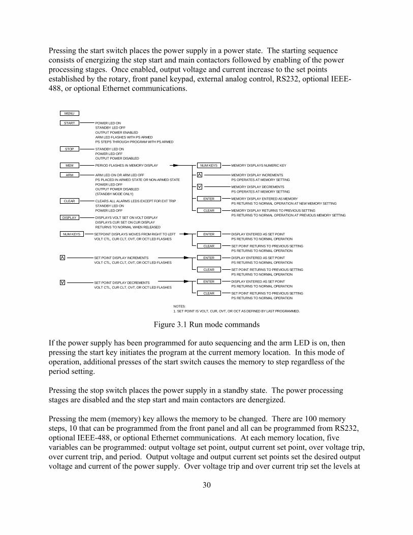
Pressing the start switch places the power supply in a power state. The starting sequenceconsists of energizing the step start and main contactors followed by enabling of the powerprocessing stages. Once enabled, output voltage and current increase to the set pointsestablished by the rotary, front panel keypad, external analog control, RS232, optional IEEE-488, or optional Ethernet communications.
Figure 3.1 Run mode commands
If the power supply has been programmed for auto sequencing and the arm LED is on, thenpressing the start key initiates the program at the current memory location. In this mode ofoperation, additional presses of the start switch causes the memory to step regardless of theperiod setting.
Pressing the stop switch places the power supply in a standby state. The power processingstages are disabled and the step start and main contactors are denergized.
Pressing the mem (memory) key allows the memory to be changed. There are 100 memorysteps, 10 that can be programmed from the front panel and all can be programmed from RS232,optional IEEE-488, or optional Ethernet communications. At each memory location, fivevariables can be programmed: output voltage set point, output current set point, over voltage trip,over current trip, and period. Output voltage and output current set points set the desired outputvoltage and current of the power supply. Over voltage trip and over current trip set the levels at
30

which the power supply will alarm if the levels are exceeded. Period, applicable in autosequence operation, determines the time period that the power supply will remain at the memorylocation before advancing to the next memory state.
After pressing the mem key, the user can enter a new memory location by pressing a number onthe keypad or by pressing the up/down keys to increment or decrement the memory location. After the selection is made, the enter key must be pressed to save the new memory location orelse the clear key can be pressed to exit without saving the new memory location.
The display key displays the voltage and current set points on the voltage and current display,respectfully. The display reverts to displaying the actual output voltage and output current whenthe display key is released. If the power supply is operating in voltage mode, then the actualoutput voltage will be close to the voltage set point and the actual output current will be less thanthe current set point. If the power supply is operating in current mode, then the actual outputcurrent will be close to the current set point and the actual output voltage will be less than thevoltage set point.
The keypad and up/down keys are active in run mode operation. A repeat last command featureallows the voltage set point, current set point, over voltage trip, over current trip, or period to bemodified without first pressing menu and item to select the parameter to be changed. Whateverparameter has been changed last is the one that will change when these key are pressed.
3.1.1.2 Set Point Commands
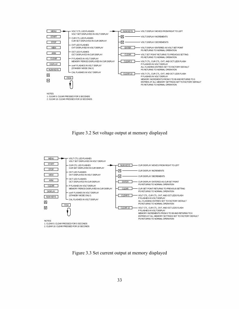
Figures 3.2 through 3.6 illustrate set point commands voltage set, current set, over voltage tripset, over current trip set, and period set, respectively. All of these commands can be made whenthe power supply is in either the standby, alarm, or power mode states.
Depending on whether the power supply is configured for rotary input or keypad input, thecommand sequence is slightly different. With the rotary configuration, voltage and current setpoint commands are entered with the front panel potentiometers and over voltage trip, overcurrent trip, and period set points are entered with the keypad. With the power supplyconfigured for keypad, all commands are entered with the keypad.
With the power supply configured for rotary, first press the menu key to enter set pointcommands. The volt ctl (voltage control) LED will initially flash. Press the item key two times.The OVT (over voltage trip) LED will flash. This indicates that a keypad or up/down entry willcreate a new OVT set point. Pressing the item key causes the OCT (over current trip) to flashindicating that a keypad or up/down entry will create a new OCT set point. Again pressing theitem key causes the P (period) in the voltage display to flash indicating that a keypad or up/downentry will create a new period set point.
With the power supply configured for keypad, first press the menu key to enter set pointcommands. The volt ctl (voltage control) LED will flash. This indicates that a keypad or
31

up/down entry will create a new voltage set point. Pressing the item key causes the cur ctl(current control) to flash indicating that a keypad or up/down entry will create a new current setpoint. Repeated pressing of the item key causes the OVT (over voltage trip) LED to flash, theOCT (over current trip) LED to flash, and P (period) in the voltage display to flash. For eachvisual indicator, entering a number with the keypad or using the up/down keys will change theset point for the parameter being indicated with the flashing LED.
In all control modes, set point voltage and current can be quickly displayed by simply pressingthe display key. This allow monitoring of both set points in standby, alarm, and power modestates.
The up/down keys have an acceleration feature to speed up entries. Pressing and holding theup/down keys cause number changes to increase or decreases at a faster rate. Upon nearing thedesired set point number, release and press again to slow down the rate of change. After theselection is made, the enter key must be pressed to save the new set point or the clear key can bepressed to exit without saving the new set point.
Pressing and holding the clear key for 5 seconds while programming set point commands sets thevoltage set point, current set point, over voltage trip, over current trip, and period for theparticular memory location to default values. Pressing and holding the clear key for 10 secondssets the same parameters of all 100 memory locations to the default parameters.
3.1.1.3 Configuration Commands
Figures 3.7 through 3.14 illustrate configuration commands set remote sense, set internal control,set external control, set rotary input, set keypad input, set external program input, set remoteinput, and set external interlock, respectively. All of these commands must be made when thepower supply is in the standby or alarm mode state.
To enter the configuration commands, first press the menu key. The volt ctl (voltage control)LED will initially flash. Then press the item key 5 times. The voltage display will flash conF(configure). Press the enter key to select configure commands. The rem sen (remote sense)LED will initially flash. To choose remote sense, press the enter key or to select otherconfiguration commands, press the item key. Each press of the item key will cause the anotherLED to flash. The order is int ctl (internal control), ext ctl (external control), rotary, keypad, extpgm (external program), remote, and loc (interlock). Further item key presses will return theconfiguration command option back to rem sen.
32
MENU VOLT CTL LEDFLASHES
CUR CTL LEDFLASHES
OVT LED FLASHES
OCT LED FLASHES
CAL FLASHES IN VOLT DISPLAY
NUM KEYS VOLT DISPLAY MOVES FROMRIGHTTO LEFT
VOLT DISPLAY INCREMENTS
VOLT DISPLAY DECREMENTS
ENTER VOLT DISPLAY ENTERED ASVOLT SET POINT
VOLT SET POINT RETURNS TO PREVIOUS SETTINGCLEAR
PS RETURNS TO NORMAL OPERATION
PS RETURNS TO NORMAL OPERATION
ITEM
VOLT SET DISPLAYED IN VOLT DISPLAY
CUR SET DISPLAYED IN CUR DISPLAY
OVT DISPLAYED IN VOLT DISPLAY
OCT DISPLAYED IN CUR DISPLAY
MEMORY PERIOD DISPLAYED IN CUR DISPLAYP FLASHES IN VOLTDISPLAY
START
STOP
ARM
CLEAR
DISPLAY
NUM KEYS
CLEAR 5 VOLT CTL, CUR CTL, OVT, AND OCT LEDS FLASHP FLASHES IN VOLTDISPLAYALL FLASHING ENTRIES SET TO FACTORYDEFAULT
ENTRIES AT ALL MEMORY SETTINGS SET TOFACTORY DEFAULTMEMORY INCREMENTS FROM 0 TO 99 ANDRETURNS TO 0P FLASHES IN VOLTDISPLAY
CLEAR 10 VOLT CTL, CUR CTL, OVT, AND OCT LEDS FLASH
PS RETURNS TO NORMAL OPERATION
NOTES:1. CLEAR 5: CLEAR PRESSED FOR 5 SECONDS2. CLEAR 10: CLEAR PRESSED FOR 10 SECONDS
PS RETURNS TO NORMAL OPERATION
MEM
(STANDBY MODE ONLY)conF FLASHES IN VOLT DISPLAY
PS RETURNS TO NORMALOPERATION
PS RETURNS TO NORMALOPERATIONCUR DISPLAY ENTERED AS CURSET POINT
CLEAR
ENTER
CUR DISPLAY MOVES FROM RIGHTTO LEFT
CUR DISPLAY DECREMENTS
CUR DISPLAY INCREMENTS
NUM KEYS
P FLASHES IN VOLTDISPLAY
OCT DISPLAYED IN CUR DISPLAY
OVT DISPLAYED IN VOLT DISPLAY
OCT LED FLASHES
OVT LED FLASHES
CUR SET DISPLAYED IN CUR DISPLAYCUR CTL LED FLASHES
VOLT SET DISPLAYED INVOLT DISPLAYVOLT CTL LEDFLASHES
CAL FLASHES IN VOLT DISPLAY
MEMORY PERIOD DISPLAYED INCUR DISPLAY
PS RETURNS TO NORMALOPERATION
VOLT CTL, CUR CTL, OVT, AND OCTLEDS FLASHCLEAR 10P FLASHES IN VOLTDISPLAYMEMORY INCREMENTS FROM 0 TO 99 AND RETURNS TO0ENTRIES AT ALL MEMORY SETTINGS SET TO FACTORY DEFAULT
ALL FLASHING ENTRIES SET TOFACTORY DEFAULTP FLASHES IN VOLTDISPLAYVOLT CTL, CUR CTL, OVT, AND OCTLEDS FLASHCLEAR 5
PS RETURNS TO NORMALOPERATION
CUR SET POINT RETURNS TO PREVIOUSSETTING
2. CLEAR 10: CLEAR PRESSED FOR 10 SECONDS1. CLEAR 5: CLEAR PRESSED FOR 5 SECONDSNOTES:
ITEM
MEM
NUM KEYS
DISPLAY
CLEAR
ARM
STOP
START
MENU
(STANDBY MODE ONLY)conF FLASHES IN VOLTDISPLAY
Figure 3.2 Set voltage output at memory displayed
Figure 3.3 Set current output at memory displayed
33

OVT DISPLAY MOVES FROM RIGHT TOLEFT
OVT DISPLAY INCREMENTS
OVT DISPLAY DECREMENTS
PS RETURNS TO NORMALOPERATION
PS RETURNS TO NORMALOPERATION
OVT DISPLAY ENTERED AS OVTSETPOINTENTER
CLEAR
NUM KEYS
P FLASHES IN VOLTDISPLAY
OCT DISPLAYED IN CUR DISPLAY
OVT DISPLAYED IN VOLT DISPLAY
OCT LED FLASHES
OVT LED FLASHES
CUR SET DISPLAYED IN CUR DISPLAYCUR CTL LED FLASHES
VOLT SET DISPLAYED INVOLT DISPLAYVOLT CTL LEDFLASHES
CAL FLASHES IN VOLT DISPLAY
MEMORY PERIOD DISPLAYED INCUR DISPLAY
PS RETURNS TO NORMALOPERATION
CLEAR 5 VOLT CTL, CUR CTL, OVT, AND OCTLEDS FLASHP FLASHES IN VOLTDISPLAYALL FLASHING ENTRIES SET TOFACTORY DEFAULT
ENTRIES AT ALL MEMORY SETTINGS SET TO FACTORY DEFAULTMEMORY INCREMENTS FROM 0 TO 99 AND RETURNS TO0P FLASHES IN VOLTDISPLAY
CLEAR 10 VOLT CTL, CUR CTL, OVT, AND OCTLEDS FLASH
PS RETURNS TO NORMALOPERATION
OVT SET POINT RETURNS TO PREVIOUS SETTING
2. CLEAR 10: CLEAR PRESSED FOR 10 SECONDS1. CLEAR 5: CLEAR PRESSED FOR 5 SECONDSNOTES:
ITEM
MEM
NUM KEYS
DISPLAY
CLEAR
ARM
STOP
START
MENU
3. ENTRIES LIMITED BETWEEN 10% AND100% FULLSCALE
(STANDBY MODE ONLY)conF FLASHES IN VOLTDISPLAY
OCT DISPLAY DECREMENTS
OCT DISPLAY INCREMENTS
OCT DISPLAY ENTERED AS OVTSETPOINT
OCT DISPLAY MOVES FROM RIGHT TOLEFT
PS RETURNS TO NORMALOPERATION
PS RETURNS TO NORMALOPERATIONCLEAR
ENTER
NUM KEYS
P FLASHES IN VOLTDISPLAY
OCT DISPLAYED IN CUR DISPLAY
OVT DISPLAYED IN VOLT DISPLAY
OCT LED FLASHES
OVT LED FLASHES
CUR SET DISPLAYED IN CUR DISPLAYCUR CTL LED FLASHES
VOLT SET DISPLAYED INVOLT DISPLAYVOLT CTL LEDFLASHES
CAL FLASHES IN VOLT DISPLAY
MEMORY PERIOD DISPLAYED INCUR DISPLAY
PS RETURNS TO NORMALOPERATION
CLEAR 5 VOLT CTL, CUR CTL, OVT, AND OCTLEDS FLASHP FLASHES IN VOLTDISPLAYALL FLASHING ENTRIES SET TOFACTORY DEFAULT
ENTRIES AT ALL MEMORY SETTINGS SET TO FACTORY DEFAULTMEMORY INCREMENTS FROM 0 TO 99 AND RETURNS TO0P FLASHES IN VOLTDISPLAY
CLEAR 10 VOLT CTL, CUR CTL, OVT, AND OCTLEDS FLASH
PS RETURNS TO NORMALOPERATION
OCT SET POINT RETURNS TOPREVIOUSSETTING
2. CLEAR 10: CLEAR PRESSED FOR 10 SECONDS1. CLEAR 5: CLEAR PRESSED FOR 5 SECONDSNOTES:
ITEM
MEM
NUM KEYS
DISPLAY
CLEAR
ARM
STOP
START
MENU
3. ENTRIES LIMITED BETWEEN 10% AND100% FULLSCALE
(STANDBY MODE ONLY)conF FLASHES IN VOLTDISPLAY
Figure 3.4 Set over voltage trip at memory displayed
Figure 3.5 Set over current trip at memory displayed
34

PS RETURNS TO NORMAL OPERATION
CLEAR
PERIOD DISPLAY ENTERED AS PERIOD SETPOINT
PERIOD DISPLAY DECREMENTS
PERIOD DISPLAY INCREMENTS
PERIOD DISPLAY MOVE FROM RIGHT TO LEFT
ENTER
NUM KEYS
PS RETURNS TO NORMAL OPERATION
P FLASHES IN VOLT DISPLAY
OCT DISPLAYED INCUR DISPLAY
OVT DISPLAYED IN VOLT DISPLAY
OCT LED FLASHES
OVT LED FLASHES
CUR SET DISPLAYED INCUR DISPLAYCUR CTL LEDFLASHES
VOLT SET DISPLAYED IN VOLTDISPLAYVOLT CTL LED FLASHES
CAL FLASHES IN VOLT DISPLAY
conF FLASHES IN VOLT DISPLAY
MEMORY PERIOD DISPLAYED IN CURDISPLAY
PS RETURNS TO NORMAL OPERATION
CLEAR 5 VOLT CTL, CUR CTL, OVT, AND OCTLEDSFLASHP FLASHES IN VOLT DISPLAYALL FLASHING ENTRIES SETTO FACTORY DEFAULT
ENTRIES AT ALL MEMORY SETTINGS SETTO FACTORYDEFAULTMEMORY INCREMENTS FROM 0 TO 99 AND RETURNS TO 0P FLASHES IN VOLT DISPLAY
CLEAR 10 VOLT CTL, CUR CTL, OVT, AND OCTLEDSFLASH
PS RETURNS TO NORMAL OPERATION
PERIOD SET POINT RETURNS TO PREVIOUSSETTING
2. CLEAR 10: CLEAR PRESSED FOR 10 SECONDS1. CLEAR 5: CLEAR PRESSED FOR 5 SECONDSNOTES:
ITEM
MEM
NUM KEYS
DISPLAY
CLEAR
ARM
STOP
START
MENU
3. SPECIAL ENTRYCODES:A. PERIOD=0: PSTURNS OFFB. PERIOD=9999: PS STAYS ON INDEFINITELYC: PERIOD=9998: RETURN TO MEMORY STATE 0
(STANDBY MODE ONLY)
Figure 3.6 Set period at memory displayed
Remote sense, internal control, external control, and interlock can be selected or deselected whenthe rem sen, int ctl, ext ctl, or loc LED is flashing. To select, press enter or to deselect, pressclear. Remote sense allows the output voltage to be sensed at the load rather than at the outputterminals of the power supply. This feature eliminates regulation degradation caused by thevoltage drop across the output cables. Details on the physical connections are covered in Section3.3.
Internal control enables the start, stop, arm, and clear keys on the front panel. External controlenables the start, stop, arm, and clear inputs at terminals 17, 19, 36, and 18 of connector JS1 onthe rear panel, respectively. Both internal control and external control may be enabled to allowsimultaneous control. Interlock requires a physical short between terminals 26 and 37 ofconnector JS1 to enable operation. This feature is useful for process control applications when asafety interlock is required. For wiring details, refer to Section 3.6.
Configuration commands for rotary, keypad, external program, and remote set the referenceinput mode for voltage set, current set, over voltage trip, and over current trip. Only one inputmode may be selected. Pressing enter when one of the respective LED is flashing causes thatmode to be selected and disables the previously selected mode. Pressing clear when therespective LED is flashing allows the user to exit the command sequence without change. Withrotary control,
35

P FLASHES IN VOLT DISPLAY
VOLT CTL LED FLASHES
VOLT SET DISPLAYED IN VOLT DISPLAY
CUR CTL LED FLASHESCUR SET DISPLAYED IN CUR DISPLAY
OVT LED FLASHES
OCT LED FLASHES
OVT DISPLAYED IN VOLT DISPLAY
OCT DISPLAYED IN CUR DISPLAY
ITEM
EXT CTL LED FLASHES
REM SEN LED FLASHES
INTERLOCK LED FLASHES
ROTARY LED FLASHES
KEYPAD LED FLASHES
EXT PGM LED FLASHES
REMOTE LED FLASHES
ENTER ENTER
CLEAR
REM SEN LED OFF
REM SEN LED ON
DISABLES REM SEN
ENABLES REM SEN
PS RETURNS TO NORMAL OPERAIONCLEAR
PS RETURNS TO NORMAL OPERATION
PS RETURNS TO NORMAL OPERATION
CAL FLASHES IN VOLT DISPLAY
MEMORY PERIOD DISPLAYED IN CUR DISPLAY
ITEM
MEM
NUM KEYS
DISPLAY
CLEAR
ARM
STOP
START
MENU
(STANDBY MODE ONLY)
conF FLASHES IN VOLT DISPLAY
INT CTL LED FLASHES
INT CTL LED FLASHES
conF FLASHES IN VOLT DISPLAY
(STANDBY MODE ONLY)
ITEM
MEM
NUM KEYS
DISPLAY
CLEAR
ARM
STOP
START
MENU
MEMORY PERIOD DISPLAYED IN CUR DISPLAY
CAL FLASHES IN VOLT DISPLAY
PS RETURNS TO NORMAL OPERATION
PS RETURNS TO NORMAL OPERATION
CLEAR PS RETURNS TO NORMAL OPERAION
ENTER
ITEM
REM SEN LED FLASHES
EXT CTL LED FLASHES
ROTARY LED FLASHES
KEYPAD LED FLASHES
EXT PGM LED FLASHES
REMOTE LED FLASHES
INTERLOCK LED FLASHES
P FLASHES IN VOLT DISPLAY
CUR CTL LED FLASHESCUR SET DISPLAYED IN CUR DISPLAY
OVT LED FLASHES
OCT LED FLASHES
OVT DISPLAYED IN VOLT DISPLAY
OCT DISPLAYED IN CUR DISPLAY
VOLT CTL LED FLASHES
VOLT SET DISPLAYED IN VOLT DISPLAY
ENTER
CLEAR
ENABLES INT CTL
INT CTL LED ON
INT CTL LED OFFDISABLES INT CTL
1. ENABLES INTERNAL START, STOP, ARM, AND CLEAR.
NOTES:
Figure 3.7 Set remote sense
Figure 3.8 Set internal control
36

DISABLES EXT CTL
EXT CTL LED OFF
EXT CTL LED ON
ENABLES EXT CTL
CLEAR
ENTER
VOLT SET DISPLAYED IN VOLT DISPLAY
VOLT CTL LED FLASHES
OCT DISPLAYED IN CUR DISPLAY
OVT DISPLAYED IN VOLT DISPLAY
OCT LED FLASHES
OVT LED FLASHES
CUR SET DISPLAYED IN CUR DISPLAYCUR CTL LED FLASHES
P FLASHES IN VOLT DISPLAY
INTERLOCK LED FLASHES
REMOTE LED FLASHES
EXT PGM LED FLASHES
KEYPAD LED FLASHES
ROTARY LED FLASHES
EXT CTL LED FLASHES
REM SEN LED FLASHES
ITEM
ENTER
PS RETURNS TO NORMAL OPERAIONCLEAR
PS RETURNS TO NORMAL OPERATION
PS RETURNS TO NORMAL OPERATION
CAL FLASHES IN VOLT DISPLAY
MEMORY PERIOD DISPLAYED IN CUR DISPLAY
MENU
START
STOP
ARM
CLEAR
DISPLAY
NUM KEYS
MEM
ITEM
(STANDBY MODE ONLY)
conF FASHES IN VOLT DISPLAY
INT CTL LED FLASHES
1. ENABLES EXTERNAL START, STOP, ARM, AND CLEAR.NOTES:
OCT DISPLAYED IN CUR DISPLAY
OVT DISPLAYED IN VOLT DISPLAY
OCT LED FLASHES
P FLASHES IN VOLT DISPLAY
VOLT SET DISPLAYED IN VOLT DISPLAY
VOLT CTL LED FLASHES
OVT LED FLASHES
CUR SET DISPLAYED IN CUR DISPLAYCUR CTL LED FLASHES
REM SEN LED FLASHES
EXT CTL LED FLASHES
ROTARY LED FLASHES
KEYPAD LED FLASHES
EXT PGM LED FLASHES
REMOTE LED FLASHES
INTERLOCK LED FLASHES
ENTER
ITEM
PS RETURNS TO NORMAL OPERAIONCLEAR
PS RETURNS TO NORMAL OPERAIONCLEAR
ENTER VOLT AND CUR CTL SET TO ROTARY
PS RETURNS TO NORMAL OPERATION
OVT AND OCT CTL SET TO KEY BOARD
ROTARY LED ON
KEYPAD, EXT PGM, AND REMOTE LED'S OFF
CAL FLASHES IN VOLT DISPLAY
MEMORY PERIOD DISPLAYED IN CUR DISPLAY
MENU
START
STOP
ARM
CLEAR
DISPLAY
NUM KEYS
MEM
ITEM
(STANDBY MODE ONLY)
conF FLASHES IN VOLT DISPLAY
INT CTL LED FLASHES
Figure 3.9 Set external control
Figure 3.10 Set rotary input
37

P FLASHES IN VOLT DISPLAYPS RETURNS TO NORMAL OPERAION
REMOTE LED FLASHES
EXT PGM LED FLASHES
ROTARY LED FLASHES
KEYPAD LED FLASHES
INTERLOCK LED FLASHES
EXT CTL LED FLASHES
REM SEN LED FLASHES
ITEM
CLEAR
ENTER
VOLT CTL LED FLASHES
OCT DISPLAYED IN CUR DISPLAY
OVT DISPLAYED IN VOLT DISPLAY
VOLT SET DISPLAYED IN VOLT DISPLAY
CUR SET DISPLAYED IN CUR DISPLAY
OCT LED FLASHES
OVT LED FLASHES
CUR CTL LED FLASHES
PS RETURNS TO NORMAL OPERAION
VOLT AND CUR CTL SET TO KEY BOARDOVT AND OCT CTL SET TO KEY BOARD
ROTARY, EXT PGM, AND REMOTE LED'S OFF
PS RETURNS TO NORMAL OPERATION
ENTER
CLEAR
KEY BOARD LED ON
CAL FLASHES IN VOLT DISPLAY
MEMORY PERIOD DISPLAYED IN CUR DISPLAY
MENU
START
STOP
ARM
CLEAR
DISPLAY
NUM KEYS
MEM
ITEM
(STANDBY MODE ONLY)conF FLASHES IN VOLT DISPLAY
INT CTL LED FLASHES
ROTARY, KEYPAD, AND REMOTE LED'S OFF
OVT AND OCT CTL SET TO EXTERNAL PROGRAMVOLT AND CUR CTL SET TO EXTERNAL PROGRAM
PS RETURNS TO NORMAL OPERATION
PS RETURNS TO NORMAL OPERAION
CUR CTL LED FLASHES
OVT LED FLASHES
OCT LED FLASHES
CUR SET DISPLAYED IN CUR DISPLAY
VOLT SET DISPLAYED IN VOLT DISPLAY
OVT DISPLAYED IN VOLT DISPLAY
OCT DISPLAYED IN CUR DISPLAY
VOLT CTL LED FLASHES
P FLASHES IN VOLT DISPLAY
REM SEN LED FLASHES
EXT CTL LED FLASHES
INTERLOCK LED FLASHES
KEYPAD LED FLASHES
ROTARY LED FLASHES
EXT PGM LED FLASHES
REMOTE LED FLASHES
PS RETURNS TO NORMAL OPERAION
ITEM
ENTER
CLEAR
CLEAR
ENTER
EXT PGM LED ON
CAL FLASHES IN VOLT DISPLAY
MEMORY PERIOD DISPLAYED IN CUR DISPLAY
MENU
START
STOP
ARM
CLEAR
DISPLAY
NUM KEYS
MEM
ITEM
(STANDBY MODE ONLY)
conF FLASHES IN VOLT DISPLAY
INT CTL LED FLASHES
Figure 3.11 Set keypad input
Figure 3.12 Set external program input
38

ROTARY, KEYPAD, AND EXT PGM LED'S OFF
OVT AND OCT CTL SET TO RS232
VOLT AND CUR CTL SET TO RS232
PS RETURNS TO NORMAL OPERATION
PS RETURNS TO NORMAL OPERATION
CUR CTL LED FLASHES
OVT LED FLASHES
OCT LED FLASHES
CUR SET DISPLAYED IN CUR DISPLAY
VOLT SET DISPLAYED IN VOLT DISPLAY
OVT DISPLAYED IN VOLT DISPLAY
OCT DISPLAYED IN CUR DISPLAY
VOLT CTL LED FLASHES
P FLASHES IN VOLT DISPLAY
REM SEN LED FLASHES
EXT CTL LED FLASHES
INTERLOCK LED FLASHES
KEYPAD LED FLASHES
ROTARY LED FLASHES
EXT PGM LED FLASHES
REMOTE LED FLASHES
PS RETURNS TO NORMAL OPERATION
ITEM
ENTER
CLEAR
CLEAR
ENTER
REMOTE LED ON
CAL FLASHES IN VOLT DISPLAY
MEMORY PERIOD DISPLAYED IN CUR DISPLAY
MENU
START
STOP
ARM
CLEAR
DISPLAY
NUM KEYS
MEM
ITEM
(STANDBY MODE ONLY)
conF FLASHES IN VOLT DISPLAY
INT CTL LED FLASHES
1. EXPANDED MEMORY IS ENABLED WITH REMOTE OPERATION.
NOTES:
2. FOR MEMORY LOCATIONS 10-99, E IS DISPLAYED IN THE MEMORY DISPLAY.
P FLASHES IN VOLT DISPLAY
CUR SET DISPLAYED IN CUR DISPLAY
VOLT SET DISPLAYED IN VOLT DISPLAY
OVT DISPLAYED IN VOLT DISPLAY
OCT DISPLAYED IN CUR DISPLAY
CUR CTL LED FLASHES
OVT LED FLASHES
OCT LED FLASHES
VOLT CTL LED FLASHES
ITEM
REM SEN LED FLASHES
INTERLOCK LED FLASHES
REMOTE LED FLASHES
EXT PGM LED FLASHES
ROTARY LED FLASHES
KEYPAD LED FLASHES
EXT CTL LED FLASHES
CLEAR
ENTER
PS RETURNS TO NORMAL OPERAION
ENTER
CLEAR
PS RETURNS TO NORMAL OPERATIONDISABLES INTERLOCK
PS RETURNS TO NORMAL OPERATIONENABLES INTERLOCK
CAL FLASHES IN VOLT DISPLAY
MEMORY PERIOD DISPLAYED IN CUR DISPLAY
MENU
START
STOP
ARM
CLEAR
DISPLAY
NUM KEYS
MEM
ITEM
(STANDBY MODE ONLY)
conF FLASHES IN VOLT DISPLAY
INT CTL LED FLASHES
Figure 3.13 Set remote input
Figure 3.14 Set external interlock
39

voltage set points and current set points are set by the front panel potentiometers and overvoltage trip and over current trip are set with the keypad. With keypad control, all four inputsare set with the keypad. By selecting external program, all reference inputs are set with theanalog inputs at terminals 3, 22, 4, and 23 of connector JS1. See Section 3.4, for connectingexternal reference inputs. By selecting remote, all reference inputs are set over the RS232network. 3.1.1.4 Calibration Commands
Figure 3.15 describes the calibration commands. Calibration commands allow calibration of fivedigital potentiometers, display of the firmware and hardware revisions, and reset the digitalpotentiometers to the factory calibration settings. All of these commands can be made when thepower supply is in either the standby or power mode state.
To enter the calibration commands, press menu and then press item 6 times. Cal (calibration)will flash in the voltage display. Press 1, 2, 3, and 4 on the keypad and then press enter or pressclear to exit the calibration command menu. Upon entering the calibration commands, theoutput voltage will be displayed in the voltage display, the potentiometer setting, P0 to P255,will be displayed in the current display, and the digital potentiometer, 1, will be displayed in thememory display. Potentiometer 1 adjusts the gain of the voltage feedback amplifier,potentiometer 2 adjusts the input offset voltage of the voltage feedback amplifier, potentiometer3 adjusts the gain of the current feedback amplifier, potentiometer 4 adjusts the input offsetvoltage of the current feedback amplifier, and potentiometer 5 adjusts the gain of the referencewhich is used for the digital to analog and analog to digital converters.
Pressing the item key advances control to potentiometer 2. The output voltage will be displayedin the voltage display, the potentiometer setting, P0 to P255, will be displayed in the currentdisplay, and the memory display will show 2 .
Pressing the item key again will advance the control to potentiometer 3. Now the output currentwill be displayed in the current display, the potentiometer setting, P0 to P255, will be displayedin the voltage display, and the memory display will show 3.
Again pressing item will advance to control potentiometer 4. The output current will bedisplayed in the current display, the potentiometer setting, P0 to P255, will be displayed thevoltage display, and the memory display will show 4 .
To advance adjustment to potentiometer 5, press the item key again. The output voltage will bedisplayed in the voltage display, the potentiometer setting, P0 to P255, will be displayed in thecurrent display, and the memory display will show 5.
40

Once a digital potentiometer has been selected for adjustment, pressing the up/down keysincrements or decrements the potentiometer setting. To save the new setting, press the enter keyor press the clear key to exit the routine. Instructions for the calibration procedure are discussedin Section 7.3.1.
After selecting digital potentiometer 5, pressing the item key displays the firmware revision inthe voltage display and the hardware revision in the current display. Pressing the item key againdisplays dEF (default) in the voltage display. Pressing the enter key resets the five digitalpotentiometers to the factory default settings.
To exit the calibration menu, press the item key until rEt (return) appears in the voltage display. Press the enter key to exit the calibration menu.
3.1.1.5 Programming Sequential Step Applications
MSD Series power supplies have the powerful feature of programming output voltage, outputcurrent, over voltage trip, over current trip, and period for 100 memory states. The differentstates can be selected by the user, timed stepped, or triggered through the front panel or rearconnector. Memory states 0 through 9 can be set though the front panel and memory states 0 to99 can be set through the RS232, optional IEEE-488, or optional Ethernet interface. When thepower supply is at memory states 10 through 99, E (extended) will be displayed in the mem(memory) display. The programming variables are defined as follows:
1. MEM: memory location for parameters stored.2. Voltage: output voltage set point. The default state is 0 Vdc and the maximum voltage
setting is the rating of the power supply.3. Current: output current set point. The default state is 0 Adc and the maximum current
setting is the rating of the power supply.4. OVT: over voltage trip. The default state and maximum settings are 110% of the voltage
rating of the power supply.5. OCT: over current. The default state and maximum settings are 110% of the current
rating of the power supply.6. Period: time period or interval at the current step. Special meanings are given to time
periods of 0, 9998, and 9999 as described below.
To initiate sequential step operation, the power supply must first be programmed and armed bypressing the arm key on the front panel or by triggering terminal 36 of JS1 located at the rear ofthe power supply. The program is initiated by pressing the start switch on the front panel or bytriggering terminal 17 of JS1. Once triggered the power supply will attempt to run through theprogram programmed for each memory step.
41

Pn SETTING ENTERED
Pn SETTING RETURNS TO
PS RETURNS TO NORMAL OPERATION
ENTER 1234 TO ENABLE CALIBRATION
DISPLAY MOVES FROM RIGHT TO LEFT
CLEAR
NUM KEYS ENTER DISPLAY VO IN VOLT DISPLAY
DISPLAY P1 SETTING IN CUR DISPLAY
DEFAULT
ITEM
NOTES:
Pn SETTING INCREMENTS
ENTER
CLEAR
P FLASHES IN VOLT DISPLAY
CUR CTL LED FLASHES
CUR SET DISPLAYED IN CUR DISPLAY
OVT LED FLASHES
OCT LED FLASHES
OVT DISPLAYED IN VOLT DISPLAY
OCT DISPLAYED IN CUR DISPLAY
VOLT SET DISPLAYED IN VOLT DISPLAY
VOLT CTL LED FLASHES
OUTPUT POWER DISABLED
POWER LED OFF
STANDBY LED ON
OUTPUT POWER ENABLED
STANDBY LED OFF
POWER LED ON
STOP
START
1. Pn SETTINGS CAN BE 0-255
PS RETURNS TO NORMAL OPERATIONCLEAR
DISPLAY dEF IN VOLT DISPLAY PS RETURNS TO NORMAL OPERATION
SETS POTENTIOMETERS TO FACTORY DEFAULTENTER
CAL FLASHES IN VOLT DISPLAY
DISPLAY 1 IN MEMORY DISPLAY
2. ALL Pn SETTINGS ARE PRECEEDED WITH P (EXAMPLE P187).
DISPLAY 2 IN MEMORY DISPLAY
DISPLAY P2 SETTING IN CUR DISPLAY
DISPLAY VO IN VOLT DISPLAY
DISPLAY IO IN CUR DISPLAY
DISPLAY P3 SETTING IN VOLT DISPLAY
DISPLAY 3 IN MEMORY DISPLAY
DISPLAY P4 SETTING IN VOLT DISPLAY
DISPLAY 4 IN MEMORY DISPLAY
DISPLAY IO IN CUR DISPLAY
DISPLAY 5 IN MEMORY DISPLAY
DISPLAY P5 SETTING IN CUR DISPLAY
DISPLAY VO IN VOLT DISPLAY
Pn SETTING DECREMENTS
MEMORY PERIOD DISPLAYED IN CUR DISPLAY
DISPLAY FIRMWARE REVISION SETTING IN VOLT DISPLAY
3. ALL REVISION SETTINGS ARE PRECEEDED WITH r (EXAMPLE r1.00).
MENU
START
STOP
ARM
CLEAR
DISPLAY
NUM KEYS
MEM
ITEM
(STANDBY MODE ONLY)
conF FLASHES IN VOLT DISPLAY
DISPLAY rEt IN VOLT DISPLAY PS RETUNS TO NORMAL OPERATIONENTER
4. RETURNS TO NORMAL AFTER 60 SECONDS OF INACTIVITY.
PREVIOUS SETTING
DISPLAY HARDWARE REVISION SETTING IN CUR DISPLAY
Figure 3.15 Calibration
42

With auto sequence operation, the memory will increment at the end of the time period or byagain pressing the start switch on the front panel or by triggering terminal 17 of JS1. This allowsthe time period programmed to be advanced or allows auto sequence operation without timeperiod programming.
Periods defined by 0, 9998, 9999 have special meaning. When a time period of 0 is encounteredin the program sequence, the power supply is set to a standby or off state. Conversely, when atime period of 9999 is encountered in the programming sequence, the power supply is set to becontinuously on. Whenever 9998 is encountered, the program jumps to memory location 0thereby allowing the power supply to create periodic waveforms.
The program can be terminated at any point in the program by pressing the stop switch or bytriggering terminal 19 of JS1. The program can be restarted at the current memory step bypressing the start switch or by triggering terminal 17 of JS1.
The power supply can always be operated with the programmed parameters at each memory stepby setting or advancing the memory step location with the memory set key.
3.1.2 MSA Series Front Panel Commands
3.1.2.1 Run Mode Commands
Figure 3.16 illustrates run mode commands. Run mode commands are used when the powersupply has been configured for the desired application.
Pressing the start switch places the power supply in a power state. The starting sequenceconsists of energizing the step start and main contactors followed by enabling of the powerprocessing stages. Once enabled, output voltage and current increase to the set pointsestablished by the rotary, external analog control, RS232, optional IEEE-488, or optionalEthernet communications.
Pressing the stop switch places the power supply in a standby state. The power processingstages are disabled and the step start and main contactors are denergized.
The V/I dis key displays the voltage and current set points on the voltage and current display,respectfully. The display reverts to displaying the actual output voltage and output current whenthe V/I dis key is released. If the power supply is operating in voltage mode, then the actualoutput voltage will be close to the voltage set point and the actual output current will be less thanthe current set point. If the power supply is operating in current mode, then the actual outputcurrent will be close to the current set point and the actual output voltage will be less than thevoltage set point.
43

MENU
START
STOP
V/I SET
CLEAR
STANDBY LED OFFPOWER LED ON
OUTPUT POWER ENABLED
OUTPUT POWER DISABLEDPOWER LED OFFSTANDBY LED ON
CLEARS ALL ALARMS LEDS EXCEPT FOR EXT TRIP
POWER LED OFF
STANDBY LED ON
RETURNS TO NORMAL WHEN RELEASED
DISPLAYS VOLT SET ON VOLT DISPLAY
DISPLAYS CUR SET ON CUR DISPLAY
DISPLAYS OCT SET ON CUR DISPLAY
DISPLAYS OVT SET ON VOLT DISPLAY
RETURNS TO NORMAL WHEN RELEASED
TRIP SET
Figure 3.16 Run mode commands
The trip dis key displays over voltage trip and over current trip on the voltage and currentdisplay, respectfully. The display reverts to displaying the actual output voltage and outputcurrent when the V/I dis key is released.
3.1.2.2 Configuration Commands
Figures 3.17 through 3.23 illustrate configuration commands set remote sense, set internalcontrol, set external control, set rotary input, set external program input, set remote input, and setexternal interlock, respectively. All of these commands must be made when the power supply isin the standby or alarm mode state.
To enter the configuration commands, first press the menu key. The voltage display will flashconF (configure). Press the enter key to select configure commands. The rem sen (remotesense) LED will initially flash. To choose remote sense, press the enter key or to select otherconfiguration commands, press the item key. Each press of the item key will cause the anotherLED to flash. The order is int ctl (internal control), ext ctl (external control), rotary, ext pgm(external program), remote, and loc (interlock). Further item key presses will return theconfiguration command option back to rem sen.
Remote sense, internal control, external control, and interlock can be selected or deselected whenthe rem sen, int ctl, ext, ext ctl, or loc LED is flashing. To select, press enter or to deselect, pressclear. Remote sense allows the output voltage to be sensed at the load rather than at the outputterminals of the power supply. This feature eliminates regulation degradation caused by thevoltage drop across the output cables. Details on the physical connections are covered in Section3.3.
44

ITEMEXT CTL LED FLASHES
REM SEN LED FLASHES
INTERLOCK LED FLASHES
ROTARY LED FLASHES
EXT PGM LED FLASHES
REMOTE LED FLASHES
ENTER ENTER
CLEARREM SEN LED OFF
REM SEN LED ON
DISABLES REM SEN
ENABLES REM SEN
PS RETURNS TO NORMAL OPERATIONCLEAR
PS RETURNS TO NORMAL OPERATION
PS RETURNS TO NORMAL OPERATION
CAL FLASHES IN VOLT DISPLAY
ITEM
V/I SET
CLEAR
TRIP SET
STOP
START
MENU
(STANDBY MODE ONLY)
conF FLASHES IN VOLT DISPLAY
INT CTL LED FLASHES
INT CTL LED FLASHES
PS RETURNS TO NORMAL OPERATION
PS RETURNS TO NORMAL OPERATION
CLEAR PS RETURNS TO NORMAL OPERATION
ENTER
ITEM
REM SEN LED FLASHES
EXT CTL LED FLASHES
ROTARY LED FLASHES
EXT PGM LED FLASHES
REMOTE LED FLASHES
INTERLOCK LED FLASHES
ENTER
CLEAR
ENABLES INT CTLINT CTL LED ON
INT CTL LED OFF
DISABLES INT CTL
1. ENABLES INTERNAL START, STOP, ARM, AND CLEAR.
NOTES:
CAL FLASHES IN VOLT DISPLAY
ITEM
V/I SET
CLEAR
TRIP SET
STOP
START
MENU
(STANDBY MODE ONLY)
conF FLASHES IN VOLT DISPLAY
DISABLES EXT CTL
EXT CTL LED OFF
EXT CTL LED ON
ENABLES EXT CTL
CLEAR
ENTER
INTERLOCK LED FLASHES
REMOTE LED FLASHES
EXT PGM LED FLASHES
ROTARY LED FLASHES
EXT CTL LED FLASHES
REM SEN LED FLASHES
ITEM
ENTER
PS RETURNS TO NORMAL OPERATIONCLEAR
PS RETURNS TO NORMAL OPERATION
PS RETURNS TO NORMAL OPERATION
INT CTL LED FLASHES
1. ENABLES EXTERNAL START, STOP, ARM, AND CLEAR.NOTES:
conF FLASHES IN VOLT DISPLAY(STANDBY MODE ONLY)
MENU
START
STOP
TRIP SET
CLEAR
V/I SET
ITEM
CAL FLASHES IN VOLT DISPLAY
Figure 3.17 Set remote sense
Figure 3.18 Set internal control
Figure 3.19 Set external control
45
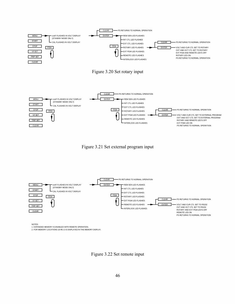
REM SEN LED FLASHES
EXT CTL LED FLASHES
ROTARY LED FLASHES
EXT PGM LED FLASHES
REMOTE LED FLASHES
INTERLOCK LED FLASHES
ENTER
ITEM
PS RETURNS TO NORMAL OPERATIONCLEAR
PS RETURNS TO NORMAL OPERATIONCLEAR
ENTER VOLT AND CUR CTL SET TO ROTARY
PS RETURNS TO NORMAL OPERATION
OVT AND OCT CTL SET TO ROTARY
ROTARY LED ONEXT PGM AND REMOTE LED'S OFF
INT CTL LED FLASHES
conF FLASHES IN VOLT DISPLAY(STANDBY MODE ONLY)
MENU
START
STOP
TRIP SET
CLEAR
V/I SET
ITEM
CAL FLASHES IN VOLT DISPLAY
ROTARY AND REMOTE LED'S OFFOVT AND OCT CTL SET TO EXTERNAL PROGRAM
VOLT AND CUR CTL SET TO EXTERNAL PROGRAM
PS RETURNS TO NORMAL OPERATION
PS RETURNS TO NORMAL OPERATION
REM SEN LED FLASHES
EXT CTL LED FLASHES
INTERLOCK LED FLASHES
ROTARY LED FLASHES
EXT PGM LED FLASHES
REMOTE LED FLASHES
PS RETURNS TO NORMAL OPERATION
ITEM
ENTER
CLEAR
CLEAR
ENTER
EXT PGM LED ON
INT CTL LED FLASHES
conF FLASHES IN VOLT DISPLAY
(STANDBY MODE ONLY)
MENU
START
STOP
TRIP SET
CLEAR
V/I SET
ITEM
CAL FLASHES IN VOLT DISPLAY
ROTARY AND EXT PGM LED'S OFF
OVT AND OCT CTL SET TO RS232VOLT AND CUR CTL SET TO RS232
PS RETURNS TO NORMAL OPERATION
PS RETURNS TO NORMAL OPERATION
REM SEN LED FLASHES
EXT CTL LED FLASHES
INTERLOCK LED FLASHES
ROTARY LED FLASHES
EXT PGM LED FLASHES
REMOTE LED FLASHES
PS RETURNS TO NORMAL OPERATION
ITEM
ENTER
CLEAR
CLEAR
ENTER
REMOTE LED ON
INT CTL LED FLASHES
1. EXPANDED MEMORY IS ENABLED WITH REMOTE OPERATION.NOTES:
2. FOR MEMORY LOCATIONS 10-99, E IS DISPLAYED IN THE MEMORY DISPLAY.
conF FLASHES IN VOLT DISPLAY
(STANDBY MODE ONLY)
MENU
START
STOP
TRIP SET
CLEAR
V/I SET
ITEM
CAL FLASHES IN VOLT DISPLAY
Figure 3.20 Set rotary input
Figure 3.21 Set external program input
Figure 3.22 Set remote input
46

ITEM
REM SEN LED FLASHES
INTERLOCK LED FLASHES
REMOTE LED FLASHES
EXT PGM LED FLASHES
ROTARY LED FLASHES
EXT CTL LED FLASHES
CLEAR
ENTER
PS RETURNS TO NORMAL OPERATION
ENTER
CLEAR
PS RETURNS TO NORMAL OPERATION
DISABLES INTERLOCK
PS RETURNS TO NORMAL OPERATIONENABLES INTERLOCK
INT CTL LED FLASHES
conF FLASHES IN VOLT DISPLAY(STANDBY MODE ONLY)
MENU
START
STOP
TRIP SET
CLEAR
V/I SET
ITEM
CAL FLASHES IN VOLT DISPLAY
Figure 3.23 Set external interlock
Internal control enables the start, stop, and clear keys on the front panel. External controlenables the start, stop, and clear inputs at terminals 17, 19, and 18 of connector JS1 on the rearpanel, respectively. Both internal control and external control may be enabled to allowsimultaneous control. Interlock requires a physical short between terminals 26 and 37 ofconnector JS1 to enable operation. This feature is useful for process control applications when asafety interlock is required. For wiring details, refer to Section 3.6.
Configuration commands for rotary, external program, and remote sets the reference input modefor voltage set, current set, over voltage trip, and over current trip. Only one input mode may beselected. Pressing enter when one of the respective LED is flashing causes that mode to selectedand disables the previously selected mode. Pressing clear when the respective LED is flashingallows the user to exit the command sequence without change. With rotary control, voltage setpoints, current set points, over voltage trip, and over current trip are set by the front panelpotentiometers. By selecting external program, all reference inputs are set with the analog inputsat terminals 3, 22, 4, and 23 of connector JS1. See Section 3.4, for connecting external referenceinputs. By selecting remote, all reference inputs are set over the RS232, optional IEEE-488, oroptional Ethernet. 3.1.2.3 Calibration Commands
Figure 3.24 describes the calibration commands. Calibration commands allow calibration of fivedigital potentiometers, display of the firmware and hardware revisions, and reset the digitalpotentiometers to the factory calibration settings. All of these commands can be made when thepower supply is in either the standby or power mode state.
To enter the calibration commands, press menu and then press item. Cal (calibration) will flashin the voltage display. Press enter for 10 seconds or press clear to exit the calibration commandmenu. Upon entering the calibration commands, the output voltage will be displayed in thevoltage display, the potentiometer setting, 0 to 255, will be displayed in the right three digits of
47

the current display, and P and 1 will alternately flash in the left digit of the current display. Potentiometer 1 adjusts the gain of the voltage feedback amplifier, potentiometer 2 adjusts theinput offset voltage of the voltage feedback amplifier, potentiometer 3 adjusts the gain of thecurrent feedback amplifier, potentiometer 4 adjusts the input offset voltage of the currentfeedback amplifier, and potentiometer 5 adjusts the gain of the reference which is used for thedigital to analog and analog to digital converters.
Pressing the item key advances control to potentiometer 2. The left digit of the current displaywill alternately flash P and 2, the output voltage will be displayed in the voltage display, and thepotentiometer setting, 0 to 255, will be displayed in the right three digits of the current display.
Pressing the item key again will advance the control to potentiometer 3. Now the output currentwill be displayed in the current display, the potentiometer setting, 0 to 255, will be displayed inthe right three digits of the voltage display, and the left digit of the voltage display willalternately flash P and 3.
Again pressing item will advance to control potentiometer 4. The left digit of the voltage displaywill alternately flash P and 4, the output current will be displayed in the current display, andpotentiometer, 0 to 255, will be displayed in the right three digits of the voltage display.
To advance adjustment to potentiometer 5, press the item key again. The left digit of the currentdisplay will alternately flash P and 5, the output voltage will be displayed in the voltage display,and the potentiometer setting, 0 to 255, will be displayed in the right three digits of the currentdisplay.
Once a digital potentiometer has been selected for adjustment, pressing the V/I dis or trip diskeys increments or decrements the potentiometer setting, respectively. To save the new setting,press the enter key or press the clear key to exit the routine. Instructions for the calibrationprocedure are discussed in Section 7.3.1.
After selecting digital potentiometer 5, pressing the item key displays the firmware revision inthe voltage display and the hardware revision in the current display. Pressing the item key againdisplays dEF (default) in the voltage display. Pressing the enter key resets the five digitalpotentiometers to the factory default settings.
To exit the calibration menu, press the item key until rEt (return) appears in the voltage display. Press the enter key to exit the calibration menu.
48

3.2 Modes of Operation
3.2.1 Normal Mode
MS series power supplies are normally shipped with its configuration set for rotary mode input,local sensing, internal control, and external control. This configuration is set by front panelcommands described in Section 3.1.1.3 and 3.1.2.2 for MSD and MSA Series power supplies,respectively. With this configuration, the operator can select either a constant voltage or aconstant current output using the front panel controls.
3.2.2 Constant Voltage
To select constant voltage output, proceed as follows:
With the supply off, set both rotary controls to full counterclockwise. Press the display key andadvance the voltage and current controls for the desired output voltage and the desired crossovercurrent. The crossover current is the current at which the power supply becomes a constantcurrent source.
Connect the load and turn on the power supply. The output voltage should be close to thevoltage set point. If a load change causes the current limit to be exceeded, the power supply willautomatically crossover to constant current output at the preset current limit and the outputvoltage will drop proportionately. In setting the current limit, allowance must be made for highpeak currents which can cause unwanted crossover (see Section 3.10).
3.2.3 Constant Current
To select constant current output, proceed as follows:
With the supply off, set both rotary controls to full counterclockwise. Press the display key andadvance the voltage and current controls for the desired output current and the desired crossovervoltage. The crossover voltage is the voltage at which the power supply becomes a constantvoltage source.
Connect the load and turn on the power supply. The output current should be close to the currentset point. If a load change causes the voltage limit to be exceeded, the power supply willautomatically crossover to constant voltage output at the preset voltage limit and the outputcurrent will drop proportionately.
49

Figure 3.24 Calibration
PS RETURNS TO NORMAL OPERATION
SETS POTENTIOMETERS TO FACTORY DEFAULTENTER
DISPLAY 1 IN MEMORY DISPLAY
2. ALL Pn SETTINGS ARE PRECEEDED WITH P AND ALTERNATE
DISPLAY 2 IN MEMORY DISPLAY
DISPLAY P2 SETTING IN CUR DISPLAY
DISPLAY VO IN VOLT DISPLAY
DISPLAY IO IN CUR DISPLAY
DISPLAY P3 SETTING IN VOLT DISPLAY
DISPLAY 3 IN MEMORY DISPLAY
DISPLAY P4 SETTING IN VOLT DISPLAY
DISPLAY 4 IN MEMORY DISPLAY
DISPLAY IO IN CUR DISPLAY
DISPLAY 5 IN MEMORY DISPLAY
DISPLAY P5 SETTING IN CUR DISPLAY
DISPLAY VO IN VOLT DISPLAY
Pn SETTING DECREMENTS
DISPLAY FIRMWARE REVISION SETTING IN VOLT DISPLAY3. ALL REVISION SETTINGS ARE PRECEEDED WITH r (EXAMPLE r1.00).
conF FLASHES IN VOLT DISPLAY
(STANDBY MODE ONLY)
MENU
START
STOP
TRIP SET
CLEAR
V/I SET
ITEM
CAL FLASHES IN VOLT DISPLAY
5. ENTER 10: ENTER PRESSED FOR 10 SECONDS.
TRIP SET
V/I SET
WITH POTENTIOMETER NUMBER. FOR EXAMPLE, POTENTIOMETER 3
SET TO 187 WILL DISPLAY P187/3187.
DISPLAY HARDWARE REVISION SETTING IN CUR DISPLAY
Pn SETTING ENTERED
Pn SETTING RETURNS TO
ENTER 10 DISPLAY VO IN VOLT DISPLAY
DISPLAY P1 SETTING IN CUR DISPLAY
DEFAULT
ITEM
NOTES:
Pn SETTING INCREMENTS
ENTER
CLEAR
OUTPUT POWER DISABLED
POWER LED OFF
STANDBY LED ON
OUTPUT POWER ENABLED
STANDBY LED OFF
POWER LED ON
STOP
START
1. Pn SETTINGS CAN BE 0-255
PS RETURNS TO NORMAL OPERATIONCLEAR
DISPLAY dEF IN VOLT DISPLAY
DISPLAY rEt IN VOLT DISPLAY PS RETUNS TO NORMAL OPERATIONENTER
4. RETURNS TO NORMAL AFTER 60 SECONDS OF INACTIVITY.
PREVIOUS SETTING
50

(b)
VO1REM-
VO1REM+
VS-
VS+
(a)
1
2
JS2
LOAD
VO-
VO+
MULTIPLEXER
MULTIPLEXER
VO+
VO-
LOAD
JS2
2
1
VS+
VS-
VO1REM+
VO1REM-
3.3 Remote Sensing
Remote sensing is available for models 1000 Vdc and below. This feature is used to improve thedegradation of regulation which will occur at the load when the voltage drop in the connectingwires is appreciable. This is done by configuring the power supply for remote sensing asdescribed in Section 3.1.1.3 and 3.1.2.2 for MSD and MSA Series power supplies, respectively. Using a pair of #20 AWG wires, connect terminal 2 of JS2 to the positive terminal of the loadand connect terminal 1 of JS2 to the negative terminal of the load. Figure 3.25 illustratesstandard output sensing and remote output sensing.
Figure 3.25 (a) Local and (b) remote sensing
51

Enabling remote sense activates the remote sense lead detector. The remote sense lead detectorchecks that the remote sense leads have been connected to the load. With the power supplyconfigured for remote sensing and upon enabling power output, the sense location is initially setto local. The sense location is switched to remote upon reaching 7.5% of full scale outputvoltage. If the voltage detected is greater than 4.5% of full scale output voltage, the senselocation remains remote; if the output voltage detected is less than 4.5%, then the sense locationwill automatically revert back to local.
The remote sense indicator on the front panel will flash when the remote sense configuration hasbeen selected and the power supply is using local sense. This can occur if the output voltagenever exceeds 7.5% of full scale output voltage or the remote sense lead detector has determinedsense leads are not connected. The remote sense indicator will remain flashing until the remotesense detector has detected the presence of remote voltage within the limits described above. 3.4 External Programming
MS series supplies allow voltage, current, voltage trip, and current trip to be programmed from aremote location. Programming can be accomplished either by resistive, voltage, or currentprogramming circuits.
Figure 3.26 illustrates the three alternatives for programming the voltage set point. The methodapplies equally to programming set point current, over voltage trip, and over current trip.
3.4.1 Resistive Programming
Resistive programming requires connection of an external potentiometer or resistors betweenterminals 21, 3, and 1 of JS1. Terminal 21 is a 10.0 V precision reference, terminal 1 is thereference ground, and terminal 3 is the voltage set point input. Like front panel rotary control,the precision reference produces a voltage across the potentiometer or resistors which is thenused to produce the voltage set point. Metal film resistors or a wire wound potentiometer willresult in the lowest temperature coefficient.
The current set point, over voltage trip, and over current trip can be programmed in the samemanner. Referring to the Table 3.1 for terminal identification, use terminal 22 to program thecurrent set point, terminal 4 to program over voltage trip, and terminal 23 to program overcurrent trip. The power supply has been calibrated to produce full scale output voltage andcurrent with 10.0 V inputs at the external reference input terminals. Furthermore, over voltageand over current trip have been calibrated to trip at 110% full scale output voltage and currentwith 10.0 V inputs at the external reference input terminals.
If the applied voltage at any input is greater than 12.50 V, the pgl (program line) LED will lightand the power supply will turn off.
Table 3.1 EXTERNAL PROGRAMMING PARAMETERS
52

TERM PARM DESCRIPTIONINPUTRANGE (V)
OUTPUTRANGE
322423
VREF EXTIREF EXTTVREF EXTTIREF EXT
Voltage SetCurrent SetOver Voltage Trip SetOver Current Trip Set
0-10.00-10.00-10.00-10.0
0-100% FS Voltage0-100% FS Current0-110% FS Voltage0-110% FS Current
3.4.2 Voltage Programming
Voltage programming is very similar to resistive programming. In this case, the voltagereference, terminal 21 of JS1, is not used and an external voltage reference is applied to theprogramming inputs directly. A 10.0 V voltage source placed between terminals 3 and 1 of JS1will produce full scale output voltage.
The current set point, over voltage trip, and over current trip can be programmed in the samemanner. Referring to the Table 3.1 for terminal identification, use terminal 22 to program thecurrent set point, terminal 4 to program over voltage trip, and terminal 23 to program overcurrent trip. The power supply has been calibrated to produce full scale output voltage andcurrent with 10.0 V inputs at the external reference input terminals. Furthermore, over voltageand over current trip have been calibrated to trip at 110% full scale output voltage and currentwith 10.0 V inputs at the external reference input terminals.
If the applied voltage at any input is greater than 12.50 V, the pgl (program line) LED will lightand the power supply will turn off.
3.4.3 Current Programming
Current programming, like voltage programming, does not require the voltage reference atterminal 21 of JS1. To produce the voltage reference, a current source is applied to a shuntresistor. Using a 2 mA current source, place a 10.0 K precision metal film resistor betweenterminals 1 and 3 of JS1. The input impedance between terminals 1 and 3 is 10K and parallelingthe additional resistor produces an equivalent resistance of 5K. The 2 mA current source willproduce 10.0 V at the external voltage reference input which will produce full scale outputvoltage.
The current set point, over voltage trip, and over current trip can be programmed in the samemanner. Referring to the Table 3.1 for terminal identification, use terminal 22 to program thecurrent set point, terminal 4 to program over voltage trip, and terminal 23 to program overcurrent trip. The power supply has been calibrated to produce full scale output voltage andcurrent with 10.0 V inputs at the external reference input terminals. Furthermore, over voltageand over current trip have been calibrated to trip at 110% full scale output voltage and current
53

Figure 3.26 External (a) resistive, (b) voltage, and © current programming
1
P/O JS1
10.00VREF
REF GND
3
RP
21
(a) (b)
VP IP
10K
(c)
REF GND
REF
VREF EXTVREF VREF
VREF EXT
REF GND
21
3
REF GND
REF10.00V
P/O JS1
1 1
P/O JS1
10.00VREF
REF GND
3
21
REF GND
VREF EXTVREF
5K
0-10.0V 0-2.0mA
RS
54

with 10.0 V inputs at the external reference input terminals.
If the applied voltage at any input is greater than 12.50 V, the pgl (program line) LED will lightand the power supply will turn off.
3.5 Voltage and Current Monitoring
Two outputs are provided for monitoring output voltage and current and for use in master/slaveseries and parallel operation. As illustrated in figure 3.27, output monitoring voltage, VO2, canbe obtained by monitoring the voltage between terminals terminal 5 of JS1 and terminal 1,2 or20 of JS1. Output monitoring current, IO2, can be obtained by monitoring the voltage between
Figure 3.27 Monitoring output (a) voltage and (b) current
terminals terminal 24 of JS1 and terminal 1,2 or 20 of JS1. Like the programming inputs, fullscale output voltage and current will produce 10.0 V. The output impedance at these terminals is100 Ω.
3.6 Digital Input and Output Lines
All digital input and output control lines are connected to connector JS1 located on the rear panel. As illustrated in figure 3.28, the digital input lines are start, stop, clear, arm, and interlock set. Functionally, the first four digital input control lines emulate the functions on the front panelwhen external control is enabled. Enabling external control and external interlock is described inSection 3.1.1.3 and 3.1.2.2 for MSD and MSA Series power supplies, respectively.
Interlock set requires a either a physical short between terminals 26 and 37 of connector JS1 orapplication of a 5.0 V source with the positive connection at terminal 37 of JS1 and the negativeconnection at terminal 7 of JS1. One of these two connections must be made to enable operation of the power supply. If the interlock connection is broken then the loc (interlock) LED lights andthe power supply shuts off. As illustrated, digital control lines may be paralleled with othersupplies to allow simultaneous control.
Digital output control lines provide the means to monitor diagnostic functions as well as mode of
1,2,20
VO2
P/O JS1
5
VO=10V FSREF GND
24IO2
IO=10V FS
55

TO SLAVES
37 INTERLOCK SET
19 STOP
START17
P/O JS1
36
26
ARM
+5
CLEAR18
operation (voltage or current). All digital output control lines, as illustrated in Figure 3.29, areconnected to connector JS1. Refer to this figure for terminal identification. Each outputmonitoring line can drive a 5.0 V, 5.0 mA load. An alarm condition will produce a 5.0 V outputat the respective terminal.
Figure 3.28 Digital input control lines
3.7 Diagnostic Functions
Diagnostic functions include thermal overload, interlock, power, standby, phase loss, programline, fuse, over voltage, and over current. All diagnostic indicators have memory retention whichsaves the fault condition until the power supply is reset. To clear a fault condition, the user mustpress the clear key on the front panel with internal control or by applying 5.0 V to terminal 18 ofJS1 with external control. Alternatively, the supply can be cleared by turning the power supplyoff and on.
Diagnostic functions and mode of control are embedded in the supply's closed loop control. Thepower supply will operate using voltage control or current control depending on which setting islowest. Voltage control and current control also contain a soft start function which causes voltageand/or current to ramp to the desired set point after power is initiated. The soft start circuitry isreset upon power-on or operation of any diagnostic function.
Thermal overload indicates that the input power processing devices or output rectifiers havereached a critical temperature. A resetting thermal breaker will reset upon cooling.
56

ALM13
33 INT CTL
EXT CTL14
OCP32
FUSE15
STANDBY28
THERMAL9
PGM LINE27
POWER8
OVP34
MONITORINGLINES
P/O JS1
30
11
VOLT CTL
CUR CTL
10
29
INTERLOCK
PHASE LOSS
7 GND
STANDBY/ALM12
Standby indicates that the control circuits are powered, but the supply is disabled through the accontactor. This is the power supply's normal off condition. To start the supply, press the startswitch. To place the supply in standby, press the stop switch.
Figure 3.29 Digital output control lines
Phase loss indicates a problem with the power mains voltage.
Program line means the voltage set point, current set point, over voltage trip, or over current tripexternal input is set beyond the range of control. These lines are constantly monitored and if anyof these references are set above the normal bounds, program line diagnostics will disable thesupply.
57

Fuse indicates that one of the three main fuses has cleared. Power must be removed from thesupply and the fuse must be replaced to correct this condition. A cleared fuse usually indicates afailed power supply requiring factory attention.
Over voltage trip indicates that the supply has exceeded the over voltage trip reference. Thiscondition causes the supply to shutdown. To clear this condition, the user must press the clearkey on the front panel with internal control or by applying 5.0 V to terminal 18 of JS1 withexternal control. To restart the supply, simply press the start switch.
Over current trip indicates that the supply has exceeded the over current trip reference. To clearthis condition, the user must press the clear key on the front panel with internal control or byapplying 5.0 V to terminal 18 of JS1 with external control. To restart the supply, simply press thestart switch.
A secondary over current trip diagnostic provides protection of internal circuitry due to abnormalline and load conditions or due to failed internal circuitry. This over current trip conditionsrequires the control power to be recycled by toggling the power switch off and on.
If external interlock is enabled, interlock set requires either a physical short between terminals 26and 37 of connector JS1 or application of a 5.0 V source with the positive connection at terminal37 of JS1 and the negative connection at terminal 7 of JS1. If the interlock connection is brokenthen the loc (interlock) LED lights and the power supply shuts down.
Standby/alm is used with master/slave operation of two or more power supplies. Wheninterconnected as illustrated in figures 3.30 or 3.31, a standby or alarm condition produced by themaster power supply will turn off the slave power supplies.
Any diagnostic condition causes an alarm condition and the alarm LED to light. This feature canbe used as an external standalone signal to indicate there is a problem.
Other indicators available for monitoring are internal control, external control, voltage modecontrol, and current mode control.
3.8 Parallel Operation
Two or more MS Series power supplies can be connected in parallel to obtain a total outputcurrent greater than that available from one power supply. The total output current is the sum ofthe output currents of the individual power supplies. Each power supply can be turned on or offseparately.
3.8.1 Parallel Operation - Direct
The simplest parallel connection involves attaching the positive terminals of all supplies to beparalleled to the positive point of the load and attaching the negative terminals to the negativepoint of the load. The output current controls of each power supply can be separately set. The
58

output voltage control of one power supply (master) should be set to the desired output voltage;the other power supply (slave) should be set for a slightly higher output voltage. The master willact as a constant voltage source; the slave will act as a constant current source, dropping its outputvoltage to equal that of the master.
3.8.2 Parallel Operation - Master/Slave
Master/slave parallel operation permits equal current sharing under all load conditions and allowscomplete control of output current from one master power supply.
Figure 3.30 illustrates the terminal connection for master/slave parallel operation and salientcontrol circuitry. The control cable can be fabricated by the user or purchased as an option,UID46, from the factory. These connections perform the following functions:
1. The current monitoring voltage, IO2, on the master power supply connects to theexternal current set point input on the slave power supply. This makes the slavepower supply operate at the same current output as the master power supply
2. The power output digital control line of the master power supply connects to thestart digital control line of the slave power supply. This connection causes theslave unit to turn on when the master unit is turned on.
3. The standby/alm digital control line of the master power supply connects to thestop digital control line of the slave power supply. This connection causes theslave unit to turn off when the master unit is turned off or when a diagnosticcondition appears.
4. Connections between terminals 4, 21, 22, and 23 set the voltage control tomaximum and set over voltage trip and over current trip to set points just beyondfull scale values. This forces the slave power supply to operate simply as a currentsource whose current set point is established by the master unit.
The slave power supply must be configured for external program input. The master unit canconfigured for rotary, keypad, external program, or remote input. Configuration commands arediscussed in Section 3.1.1.3 and 3.1.2.2 for MSD and MSA Series power supplies, respectively.
To add a second slave unit, connect the output terminals of the second slave in parallel with theother two power supplies. Furthermore, connect a second control cable between the second slaveunit and the master unit.
3.9 Series Operation
Two or more power supplies can be connected in series to obtain a total output voltage greaterthan that available from one power supply. The total output voltage is the sum of the outputvoltage of the individual power supplies. Each power supply can be turned on or off separately.
59
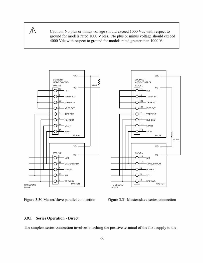
Caution: No plus or minus voltage should exceed 1000 Vdc with respect toground for models rated 1000 V less. No plus or minus voltage should exceed4000 Vdc with respect to ground for models rated greater than 1000 V.
Figure 3.30 Master/slave parallel connection Figure 3.31 Master/slave series connection
3.9.1 Series Operation - Direct
The simplest series connection involves attaching the positive terminal of the first supply to the
P/O JS1
22
2
VO+
VO-
LOAD
SLAVE
CURRENTMODE CONTROL
MASTERREF GND
VO-
VO+
IO2
2
24
P/O JS1
TO SECONDSLAVE
REF GND
IREF EXT VREF EXT
REF GND
SLAVETO SECOND
P/O JS1
5
2
VO2
VO+
VO-
REF GNDMASTER
MODE CONTROLVOLTAGE
SLAVE
LOAD
VO-
VO+
2
3
P/O JS1
12STANDBY/ALM
POWER8
START
STOP19
17
21REF
TVREF EXT4
23TIREF EXT
3VREF EXT
POWER
STANDBY/ALM
8
12
17
19STOP
START
IREF EXT22
TIREF EXT23
4TVREF EXT
21REF
VO25
IO224
60

negative terminal of the second supply. The load is connected between the negative terminal ofthe first supply and the positive terminal of the second supply. The output current controls ofeach power supply are operative and the current limit is equal to the lowest control setting. If anyone output current control is set too low with respect to the total output current, the series powersupplies will automatically crossover to constant current operation and the output voltage willdrop.
3.9.2 Series Operation - Master/Slave
Master/slave series operation permits equal voltage sharing under all load conditions and allowscomplete control of output voltage from one master power supply.
Figure 3.31 illustrates the terminal connection for master/slave series operation and salient controlcircuitry. The control cable can be fabricated by the user or purchased as an option, UID46, fromthe factory. These connections perform the following functions:
1. The voltage monitoring voltage, VO2, on the master power supply connects to theexternal voltage set point input on the slave power supply. This makes the slavepower supply operate at the same voltage output as the master power supply
2. The power output digital control line of the master power supply connects to thestart digital control line of the slave power supply. This connection causes theslave unit to turn on when the master unit is turned on.
3. The standby/alm digital control line of the master power supply connects to thestop digital control line of the slave power supply. This connection causes theslave unit to turn off when the master unit is turned off or when a diagnosticcondition appears.
4. Connections between terminals 4, 21, 22, and 23 set the current control tomaximum and set over voltage trip and over current trip to set points just beyondfull scale values. This forces the slave power supply to operate simply as a voltagesource whose voltage set point is established by the master unit.
The slave power supply must be configured for external program input. The master unit canconfigured for rotary, keypad, external program, or remote input. Configuration commands arediscussed in Section 3.1.1.3 and 3.1.2.2 for MSD and MSA Series power supplies, respectively.
To add a second slave unit, connect the output terminals of the second slave in series with theother two power supplies. Furthermore, connect a second control cable between the second slaveunit and the master unit.
61

3.10 Pulse Loading
The power supply will automatically crossover from constant voltage to constant currentoperation, or the reverse, in response to an increase (over the preset limit) in the output current orvoltage, respectively. With the preset limit set to the average output current or voltage, high peakcurrents or voltages, as occur in pulse loading, may exceed the preset limit conditions and causecrossover to occur. To avoid this unwanted crossover, the preset limit must be set for the peakrequirement and not the average.
There are internal capacitors across the output terminals of the power supply. These capacitorshelp to supply high-current pulses of short duration during constant voltage operation. Anycapacitance added externally will improve the pulse current capability, but will decrease thesafety provided by the constant current circuit. A high-current pulse may damage loadcomponents before the average output current is large enough to cause the constant current circuitto operate.
3.11 Nomenclature
The following defines user connections on the terminal strips and input/output powerconnections.
AC INPUT:
A: Phase A input.
B: Phase B input.
C: Phase C input.
GND: Earth ground.
DC OUTPUT:
VO+: Positive output.
VO- : Negative output.
PROGRAMMING INPUTS AND OUTPUTS:
REF GND: Reference ground.
+10V REF: Reference for external analog control.
+2.5V REF CAL: Reference used for the calibration procedure.
62

VO1REM+: Remote positive voltage sense.
VO1REM-: Remote negative voltage sense.
VO2: Output monitoring voltage.
IO2: Output monitor current.
VREF: Voltage set point reference.
IREF: Current set point reference.
TVREF: Over voltage trip reference.
TIREF: Over current trip reference.
VMOD: Modulation input voltage.
DIGITAL INPUT CONTROL LINES:
STOP: Remote stop.
START: Remote start.
CLEAR: Clear.
ARM: Arm.
INTERLOCK SET: Interlock set.
DIGITAL OUTPUT CONTROL LINES:
STANDBY: Standby.
POWER: Control circuit power.
INT CTL: Internal control.
EXT CTL: External control.
PGL: Program line shutdown.
OVT: Over voltage trip shutdown.
63

OCT: Over current trip shutdown.
PHL: Phase loss shutdown.
THL: Thermal overload shutdown.
FSE: Fuse cleared.
VOLT CTL: Voltage control.
CUR CTL: Current control.
LOC: Interlock open.
STANDBY/ALM: Standby or alarm.
ALM: Alarm condition.
FRONT PANEL:
PWR: Control power.
MENU: menu.
ENTER: enter.
ITEM: specific item within menu selection.
V/I DIS: displays voltage and current set point.
TRIP DIS: displays over voltage trip and over current trip set point.
MEM: Memory.
REM SEN: Remote sense.
INT CTL: Internal control.
EXT CTL: External control.
ROTARY: Front panel potentiometer voltage and current control.
KEYPAD: Keypad control.
EXT PGM: External analog control.
64

REMOTE: RS232 control.
65

4.0 PROGRAMMING WITH SCPI COMMANDS
4.1 Command Features
The MS Series power supplies provide RS232 communications as a standard feature and IEEE-488 or Ethernet communications as an optional feature. A second UART port, a factory installedoption, is enabled after power on by recognizing which port is receiving communications. Once aparticular port has been activated, the other UART port cannot be recognized unless there hasbeen a period of inactivity for 5 minutes. After this period, a new UART port can be recognizedby sending communications.
In addition to RS232, IEEE-488, or Ethernet communications, other communications options arepossible using external RS232 converter modules. These modules transparently converts databetween the RS232 port and the one tied to communications system. Refer to the Appendixes fordetails on the optional communications ports and the external converter modules.
An IVI-COM Driver is included with the installation CD and is available for download from theMagna-Power Electronics’ web page. The driver allows the power supply to communicatethrough many different programming languages. The driver handles the low-level bus protocolssimplifying automation development. It supports TCP/IP, GPIB, and RS232 using standard VISAresource descriptors. For additional documentation and details on using the IVI-COM driver, seethe driver's included help file (MPEIVI.chm).
The RS232 port, connector JS3, located on the rear panel, allows all of the front panel functionsplus some additional commands to be implemented using SCPI commands. To establish RS232communications, configure the power supply for remote operation using the front panelcommands described in Sections 3.1.1.3 or 3.1.2.2, set the RS232 interface to the specificationsdetailed in Section 1.5, and connect a 9-conductor straight through, D-subminiature cablebetween the computer interface and connector JS3.
RS232 communications to the MS Series power supply can be made using a Terminal program orwith the Remote Interface Software supplied with the power supply. The Remote InterfaceSoftware, covered in Section 5.0, contains command output frames to display the SCPI commandbeing written to obtain the desired result. This feature provides feedback to the user to helpprogram with SCPI commands.
4.2 Electrical Testing Using RS232 Communications
MS Series power supplies can be tested using any Terminal program; one is included withMicrosoft Windows (tm) called HyperTerminal. The following outlines the procedure.
1. Configure the power supply for remote operation using the front panel commandsdescribed in Section 3.1.1.3 and 3.1.2.2 for MSD and MSA Series power supplies,respectively.
2. Connect a 9-conductor straight through, D-subminiature cable between the computer
66

interface and connector JS3 at the rear of the power supply.3. Verify the availability of the RS232 port selected.4. Turn on the power switch of the MS Series power supply and turn on the IBM PC or
compatible computer.5. Start the HyperTerminal test software and set the COM port to the one connected to the
MS Series power supply. Configure the terminal for 19200, N, 8, 1. Set the terminal toecho typed characters locally and “append line feeds to incoming line ends.” (The echofeature is not functional with Windows 98.)
6. Type the query command “*IDN?” in the output data window and press enter. The textshould be entered inside the quotation marks.
7. As illustrated in figure 4.1, the returned data will display the following:“Magna-Power Electronics, Inc., MSD16-1800, SN: 1161-0361” where the model andserial number may be different depending on the unit being tested.
8. Verify that the model number in the *IDN? response corresponds to the power supplyunder test. If this is not the case, configure the supply using the steps outlined in Section4.3.9.1 CAL:IDN.
9. With the output terminals of the power supply open, enter the command VOLT xx wherexx is 50% of rated voltage and press enter. Press the display key on the front panel of thepower supply and verify that the set point is 50% of rated voltage.
10. Enter the command OUTP:START and press enter. The power supply’s contactor shouldclose with an audible click and the front panel indicators and meters should indicatepower flow. Verify that the power supply’s output voltage is equal to the VOLT settingset in the previous command.
11. Enter the command MEAS:VOLT? and press enter. Verify the output voltagecorresponds the voltmeter on the front panel of the power supply.
12. Enter the command OUTP:STOP and press enter. The power supply’s contactor shouldopen with an audible click and the front panel indicators and meters should indicateoperation in a standby state.
4.3 SCPI Subsystem Commands
The SCPI command set is broken down into sub-systems as described in the following Sections ofthis chapter. The syntax for data formats of the SCPI command set is defined in Section 4.3.15.
4.3.1 Source Subsystem
This subsystem programs the voltage set point, current set point, over voltage trip, over currenttrip, and period of the power supply.
67
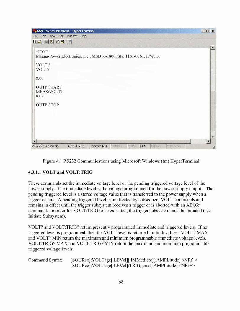
Figure 4.1 RS232 Communications using Microsoft Windows (tm) HyperTerminal
4.3.1.1 VOLT and VOLT:TRIG
These commands set the immediate voltage level or the pending triggered voltage level of thepower supply. The immediate level is the voltage programmed for the power supply output. Thepending triggered level is a stored voltage value that is transferred to the power supply when atrigger occurs. A pending triggered level is unaffected by subsequent VOLT commands andremains in effect until the trigger subsystem receives a trigger or is aborted with an ABORtcommand. In order for VOLT:TRIG to be executed, the trigger subsystem must be initiated (seeInitiate Subsystem).
VOLT? and VOLT:TRIG? return presently programmed immediate and triggered levels. If notriggered level is programmed, then the VOLT level is returned for both values. VOLT? MAXand VOLT? MIN return the maximum and minimum programmable immediate voltage levels. VOLT:TRIG? MAX and VOLT:TRIG? MIN return the maximum and minimum programmabletriggered voltage levels.
Command Syntax: [SOURce]:VOLTage[:LEVel][:IMMediate][:AMPLitude] <NRf+>[SOURce]:VOLTage[:LEVel]:TRIGgered[:AMPLitude] <NRf+>
68
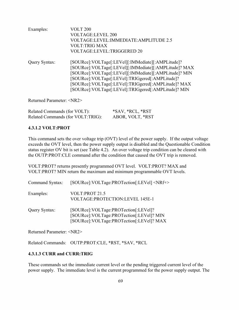
Examples: VOLT 200VOLTAGE:LEVEL 200VOLTAGE:LEVEL:IMMEDIATE:AMPLITUDE 2.5VOLT:TRIG MAXVOLTAGE:LEVEL:TRIGGERED 20
Query Syntax: [SOURce]:VOLTage[:LEVel][:IMMediate][:AMPLitude]?[SOURce]:VOLTage[:LEVel][:IMMediate][:AMPLitude]? MAX[SOURce]:VOLTage[:LEVel][:IMMediate][:AMPLitude]? MIN[SOURce]:VOLTage[:LEVel]:TRIGgered[:AMPLitude]?[SOURce]:VOLTage[:LEVel]:TRIGgered[:AMPLitude]? MAX[SOURce]:VOLTage[:LEVel]:TRIGgered[:AMPLitude]? MIN
Returned Parameter: <NR2>
Related Commands (for VOLT): *SAV, *RCL, *RSTRelated Commands (for VOLT:TRIG): ABOR, VOLT, *RST
4.3.1.2 VOLT:PROT
This command sets the over voltage trip (OVT) level of the power supply. If the output voltageexceeds the OVT level, then the power supply output is disabled and the Questionable Conditionstatus register OV bit is set (see Table 4.2). An over voltage trip condition can be cleared withthe OUTP:PROT:CLE command after the condition that caused the OVT trip is removed.
VOLT:PROT? returns presently programmed OVT level. VOLT:PROT? MAX andVOLT:PROT? MIN return the maximum and minimum programmable OVT levels.
Command Syntax: [SOURce]:VOLTage:PROTection[:LEVel] <NRf+>
Examples: VOLT:PROT 21.5 VOLTAGE:PROTECTION:LEVEL 145E-1
Query Syntax: [SOURce]:VOLTage:PROTection[:LEVel]?[SOURce]:VOLTage:PROTection[:LEVel]? MIN[SOURce]:VOLTage:PROTection[:LEVel]? MAX
Returned Parameter: <NR2>
Related Commands: OUTP:PROT:CLE, *RST, *SAV, *RCL
4.3.1.3 CURR and CURR:TRIG
These commands set the immediate current level or the pending triggered current level of thepower supply. The immediate level is the current programmed for the power supply output. The
69

pending triggered level is a stored current value that is transferred to the power supply outputwhen a trigger occurs. A pending triggered level is unaffected by subsequent CURR commandsand remains in effect until the trigger subsystem receives a trigger or is aborted with an ABORtcommand. In order for CURR:TRIG to be executed, the trigger subsystem must be initiated (seeINITiate).
CURR? and CURR:TRIG? return presently programmed immediate and triggered levels. If notriggered level is programmed, then the CURR level is returned for both values. CURR? MAXand CURR? MIN return the maximum and minimum programmable immediate current levels. CURR:TRIG? MAX and CURR:TRIG? MIN return the maximum and minimum programmabletriggered current levels.
Command Syntax: [SOURce]:CURRent[:LEVel] [:IMMediate][:AMPLitude] <NRf+>[SOURce]:CURRent[:LEVel]:TRIGgered [:AMPLitude] <NRf+>
Examples: CURR 200 CURRENT:LEVEL MINCURRENT:LEVEL:IMMEDIATE:AMPLITUDE 2.5CURR:TRIG 20 CURRENT:LEVEL:TRIGGERED 20
Query Syntax: [SOURce]:CURRent[:LEVel][:IMMediate][:AMPLitude]?[SOURce]:CURRent[:LEVel] [:IMMediate][:AMPLitude]? MAX[SOURce]:CURRent[:LEVel] [:IMMediate][:AMPLitude]? MIN[SOURce]:CURRent[:LEVel]:TRIGgered [:AMPLitude]?[SOURce]:CURRent[:LEVel]:TRIGgered [:AMPLitude]? MAX[SOURce]:CURRent[:LEVel]:TRIGgered [:AMPLitude]? MIN
Returned Parameter: <NR2>
Related Commands (for CURR): *SAV, *RCL, *RSTRelated Commands (for CURR:TRIG): ABOR, CURR, *RST
4.3.1.4 CURR:PROT
This command sets the over current trip (OCT) level of the power supply. If the output currentexceeds the OCT level, then the power supply output is disabled and the Questionable Conditionstatus register OC bit is set (see Table 4.2). An over current trip condition can be cleared with theOUTP:PROT:CLE command after the condition that caused the OCT trip is removed.
CURR:PROT? returns presently programmed OCT level. CURR:PROT? MAX andCURR:PROT? MIN return the maximum and minimum programmable OCP levels.
Command Syntax: [SOURce]:CURRent:PROTection[:LEVel] <NRf+>
70

Examples: CURR:PROT MAXCURRENT:PROTECTION:LEVEL 145E-1
Query Syntax: [SOURce]:CURRent:PROTection[:LEVel]?[SOURce]:CURRent:PROTection [:LEVel]? MIN[SOURce]:CURRent:PROTection [:LEVel]? MAX
Returned Parameter: <NR2>
Related Commands: OUTP:PROT:CLE, *RST, *SAV, *RCL
4.3.1.5 PER (MSD Series only)
This command sets the period of time that the power supply will remain in the state during autosequence operation. The minimum unit for the period command is 10 msec and the maximumunit is 9997 sec. There are 3 reserved numbers associated with this command, namely: 0, 9998and 9999. When a 0 is detected in auto sequence operation, the power supply will stop as if astop command condition (see OUTP:STOP) occurred. When a 9998 is detected, the followingmemory location will be zero. When 9999 is detected, the power supply will operate at thatmemory state indefinitely or until stop (see OUTP:STOP) is commanded. The period’s durationcan be overridden by the using the start command (see OUTP:START) to advance the memory tothe next state or the stop command OUTP:STOP) to stop the power supply.
PER? returns the period at the current memory.
Command Syntax: [SOURce]:PERiod <NRf+>
Examples: SOUR:PER 200SOURCE:PERIOD 1345SOUR:PER MAX
Query Syntax: [SOURCE]:PERiod? <>[SOURCE]:PERiod? MIN[SOURCE]:PERiod? MAX
Returned Parameters: <NR1>
Related Commands: *RST, OUTP:START, OUTP:STOP, OUTP:ARM
4.3.2 Measure Subsystem
The Measure Subsystem returns the voltage and current measured at the output of the powersupply.
71

4.3.2.1 MEAS:VOLT?
Query Syntax: MEASure:VOLTage[:DC]? <>
Examples: MEAS:VOLT?MEASURE:VOLTAGE:DC?
Returned Parameters: <NR2>
4.3.2.2 MEAS:CURR?
Query Syntax: MEASure:CURRent[:DC]? <>
Examples: MEAS:CURR?MEASURE:CURRENT:DC?
Returned Parameters: <NR2>
4.3.3 System Subsystem
The System subsystem returns information about the state of the power supply.
4.3.3.1 SYST:VERS?
This query returns the firmware and hardware version of the power supply. The returned valuehas the form Firmware Rev. X.X, Hardware Rev. X.X.
Query Syntax: SYSTem:VERSion? <>
Examples: SYST:VERS?SYSTEM:VERSION?
Returned Parameters: <Firmware Rev. XX.Y, Hardware Rev. XX.Y>
Related Commands: None
4.3.3.2 SYST:ERR?
The SYST:ERR? query returns the error messages that have occurred in the system. The formatof the return string is an error number followed by a corresponding error message string. Theerrors are stored in a FIFO (first-in, first-out) buffer. As the errors are read, they are removedfrom the queue. When all errors have been read, the query returns 0,”NO ERROR.” If moreerrors have accumulated than the queue can hold, the last error in the queue will be -350,”QueueOverflow” (see Table 4.7, Error Messages, for other error codes).
72

Query Syntax: SYSTem:ERRor? <>
Examples: SYST:ERR?SYSTEM:ERROR?
Returned Parameters: <error number>,<error string>
Related Commands: None
4.3.4 Status Subsystem
This subsystem programs the power supply status registers. The power supply has three groupsof status registers: Operation, Questionable, and Standard Event. The Operation andQuestionable Condition registers monitor the power supply’s operation and alarm status. TheStandard Event group is programmed with Standard Commands as described in Section 4.5, IEEE488 Event Processing.
4.3.4.1 Operation Register
This query returns the value of the Operation Register which is a read-only register that holds thereal-time (unlatched) condition of the operational status of the power supply. The bitconfiguration of the Operation Register is shown in Table 4.1.
Query Syntax: STATus:OPERation:CONDition? <>
Examples: STAT:OPER:COND?STATUS:OPERATION:CONDITION?
Returned Parameters: <NR1> (Register value)
Related Commands: None
Table 4.1 BIT CONFIGURATION OF THE OPERATION REGISTERBIT WEIGHT ABBREVIATION DESCRIPTION0 1 ARM Arm1 2 SS Soft Start2 4 LOCK Locked3 8 INT Internal Control4 16 EXT External Control5 32 WTG Interface is waiting for trigger6 64 STBY Standby7 128 PWR Power8 256 CV Constant Voltage9 512 RSEN Remote Sense
73

10 1024 CC Constant Current11 2048 STBY/ALM Standby or Alarm12-15 NU
4.3.4.2 Questionable Register
This query returns the value of the Questionable Register. The Questionable Register is a read-only register that holds the real-time (unlatched) condition of the questionable status of the powersupply. The bit configuration of the Questionable Register is shown in the Table 4.2.
Table 4.2 BIT CONFIGURATION OF QUESTIONABLE REGISTERBIT WEIGHT ABBREVIATION DESCRIPTION0 1 OV Over Voltage Tripped1 2 OC Over Current Tripped2 4 PB Phase Balance Protection Tripped3 8 PGM Program Line Protection Tripped4 16 OT Over Temperature Protection Tripped5 32 FUSE Fuse Protection Tripped6 64 NU Not used7 128 ALM Alarm Protection Tripped8 256 ILOC Interlock9 512 REM Remote10-15 NU Not used
Query Syntax: STATus:QUEStionable:CONDition? <>
Examples: STAT:QUES:COND?STATUS:QUESTIONABLE:CONDITION?
Returned Parameters: <NR1> (Register value)
Related Commands: None
4.3.5 Output Subsystem
This subsystem returns or controls the output state of the power supply.
4.3.5.1 OUTP?
This query returns the output state of the power supply. A 1 indicates the power supply isenergized, and a 0 indicates the power supply is off.
Command Syntax: none
74

Query Syntax: OUTPut[:STATe]?
Returned Parameters: 0 | 1
Related Commands: *RST, *RCL, *SAV
4.3.5.2 OUTP:ARM (MSD Series only)
This command selects between the modes of operation. There are two modes of operation for thepower supply: normal mode and auto sequence mode. Normal mode energizes the currentparameters of the supply until stopped. Auto sequence mode sequentially steps through thememory updating the supply’s parameters as it increments. Each memory location contains thevoltage set point, current set point, over voltage trip, over current trip, and period. The periodparameter specifies the time period for operating at the memory location when auto sequenceoperation is deployed. When enabled, the ARM light lights on the front panel.
To initiate a program sequence, select the starting memory location, execute this command, andissue an OUPT:START (see OUTP:START) or use the front panel start switch. The ARM lightwill blink after the start command. If this process reaches the upper memory limit, memorylocation 99, the following memory location will revert back to 0 and continue. Auto sequenceoperation will continue until an OUTP:STOP is commanded or a memory location with period setto 0 is encountered.
ARM? returns the arm state of the power supply.
Command Syntax: OUTP:ARM <bool>
Parameters: 0 | OFF | 1 | ON
Examples: OUTP:ARM OFFOUTP:ARM 1
Query Syntax: OUTP:ARM?
Returned Parameters: 0 | 1
Related Commands: *RST, OUTP:START, OUTP:STOP
4.3.5.3 OUTP:START
This command closes the power supply’s input contactor and initiates either normal or programmode. Auto sequence mode will be initiated if the ARM option is enabled. Normal modeenergizes the power supply with the current parameters for voltage set point, current set point,over voltage trip, and over current trip. Auto sequence mode will sequentially step through
75

memory locations until the stop is commanded, OUTP:STOP, or a terminating condition isreached (see PER, OUTP:STOP).
Command Syntax: OUTPut:START <>
Examples: OUTP:STARTOUTPUT:START
Query Syntax: none
Related Commands: *RST, OUTP:STOP, OUTP:ARM, PER
4.3.5.4 OUTP:STOP
This command opens the power supply’s input contactor and terminates operation in eithernormal mode or auto sequence mode.
Command Syntax: OUTPut:STOP <>
Examples: OUTP:STOPOUTPUT:STOP
Query Syntax: none
Related Commands: *RST, OUTP:START, OUTP:ARM, PER
4.3.5.5 OUTP:PROT:CLE
This command clears the alarm latches. There are seven alarm latches, namely: interlock,program line, phase balance, thermal, over voltage trip, over current trip, and fuse. When a fault isdetected, the power supply is rendered to an alarm state. The power supply cannot be restarteduntil the protection condition is cleared and the latch is reset.
Command Syntax: OUTPut:PROTection:CLEar <>
Examples: OUTP:PROT:CLEOUTPUT:PROTECTION:CLEAR
Query Syntax: none
Related Commands: *RST, *RCL, *SAV
4.3.6 Abort Subsystem
76
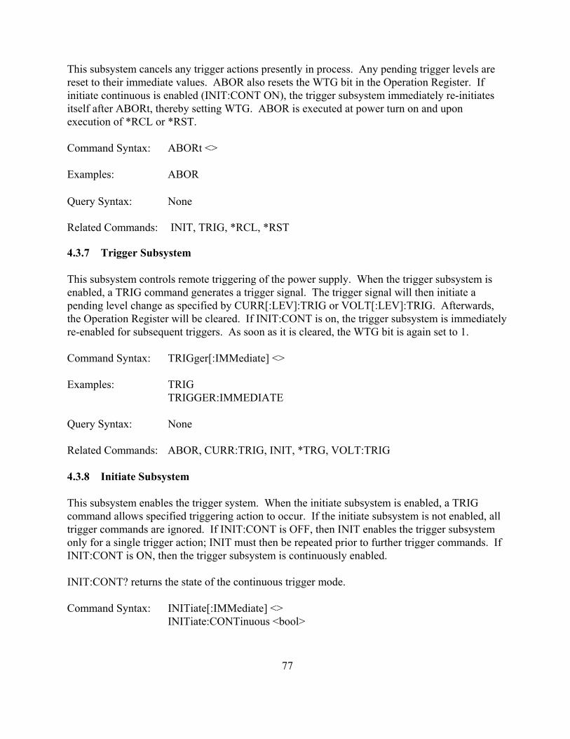
This subsystem cancels any trigger actions presently in process. Any pending trigger levels arereset to their immediate values. ABOR also resets the WTG bit in the Operation Register. Ifinitiate continuous is enabled (INIT:CONT ON), the trigger subsystem immediately re-initiatesitself after ABORt, thereby setting WTG. ABOR is executed at power turn on and uponexecution of *RCL or *RST.
Command Syntax: ABORt <>
Examples: ABOR
Query Syntax: None
Related Commands: INIT, TRIG, *RCL, *RST
4.3.7 Trigger Subsystem
This subsystem controls remote triggering of the power supply. When the trigger subsystem isenabled, a TRIG command generates a trigger signal. The trigger signal will then initiate apending level change as specified by CURR[:LEV]:TRIG or VOLT[:LEV]:TRIG. Afterwards,the Operation Register will be cleared. If INIT:CONT is on, the trigger subsystem is immediatelyre-enabled for subsequent triggers. As soon as it is cleared, the WTG bit is again set to 1.
Command Syntax: TRIGger[:IMMediate] <>
Examples: TRIGTRIGGER:IMMEDIATE
Query Syntax: None
Related Commands: ABOR, CURR:TRIG, INIT, *TRG, VOLT:TRIG
4.3.8 Initiate Subsystem
This subsystem enables the trigger system. When the initiate subsystem is enabled, a TRIGcommand allows specified triggering action to occur. If the initiate subsystem is not enabled, alltrigger commands are ignored. If INIT:CONT is OFF, then INIT enables the trigger subsystemonly for a single trigger action; INIT must then be repeated prior to further trigger commands. IfINIT:CONT is ON, then the trigger subsystem is continuously enabled.
INIT:CONT? returns the state of the continuous trigger mode.
Command Syntax: INITiate[:IMMediate] <>INITiate:CONTinuous <bool>
77

Parameters (for INIT[:IMM]): NoneParameters (for INIT:CONT): 0 | 1 | OFF | ON
Examples INIT INITIATE:IMMEDIATEINIT:CONT 1 INITIATE:CONTINUOUS OFF
Query Syntax (for INIT[:IMM]): NoneQuery Syntax (for INIT:CONT): INIT:CONT?
Returned Parameters: 0 | 1
Related Commands: ABOR, *RST, TRIG
4.3.9 Calibrate Subsystem
The Calibrate Subsystem calibrates the power supply.
4.3.9.1 CAL:IDN
This command updates the power supply’s identification string for the power supply model. TheCAL:IDN string can have up to 100 characters.
Command Syntax: CALibrate:IDN <string>Parameters: Company Name, Power Supply Model, S/N (string format)
where: Company Name = "Magna-Power Electronics, Inc.,"Power Supply Model = PS Type+PSVolts+”-“+PSAmps +”,” (The Power Supply type can be MSD, MSA, or MSC)S/N = “S/N: xxx-yyyy”
Examples: For a MSD supply rated at 16VDC and 1800 ADCcal:idn Magna-Power Electronics, Inc., MSD16-1800, S/N: 1161-0361,F/W:1.0
Query Syntax: CAL:IDN?
Returned Parameters: <string>
Related Commands: *IDN
4.3.9.2 CAL:PASS
78

This command protects against system calibration corruption and initiates the calibrationsequence.
Command Syntax: CAL:PASS <NR1>
Examples: CALIBRATE:PASSWORD 1234CAL:PASS 1234
Query Syntax: None
Related Commands: None
4.3.9.3 CAL:POT
This command sets the value for the specified potentiometer. The variable specifies thepotentiometer to be adjusted, 1 thru 5, and the second variable specifies the potentiometer setting,0 through 255.
Command Syntax: CALibrate:POT <NR1>,<NR1>
Examples: CAIBRATE:POT 1,123CAL:POT 5,11
Query Syntax: CALibrate:POT? <NR1>
Returned Parameters: <NR1>
Related Commands: None
4.3.9.4 CAL:SCAL:VOLT
This command sets the voltage scale factor for the power supply.
Command Syntax: CALibrate:SCALe:VOLTage <NRf>
Examples: CALIBRATE:SCALE:VOLTAGE 16.0CAL:SCAL:VOLT 16.0
Query Syntax: CALibrate:SCALe:VOLTage? <>
Returned Parameters: <NR3>
Related Commands: None
79

4.3.9.5 CAL:SCAL:CURR
This command sets the current scale factor for the power supply.
Command Syntax: CALibrate:SCALe:CURRent <NRf>
Examples: CALIBRATE:SCALE:CURRENT 900.0CAL:SCAL:CURR 900.0
Query Syntax: CALibrate:SCALe:CURRent? <>
Returned Parameters: <NR3>
Related Commands: None
4.3.9.6 CAL:SCAL:INP
This command sets the full scale external programming inputs for voltage, current, over voltagetrip, and over current trip. The scaling factor for the programming inputs must match the scalingfactor set with hardware on the control board.
Command Syntax: CALibrate:SCALe:INPut <NRf>
Examples: CALIBRATE:SCALE:INPUT 10.0CAL:SCAL:INP 10.0
Query Syntax: CALibrate:SCALe:INPut? <>
Returned Parameters: <NR3>
Related Commands: None
4.3.9.7 CAL:DEF
This command sets the calibration potentiometers to the factory defaults.
Command Syntax: CALibrate:DEFaults <>
Examples: CALibrate:DEFaultsCAL:DEF
Query Syntax: None
80

Related Commands: None
4.3.9.8 CAL:STOP
This command terminates the calibration subsystem.
Command Syntax: CALibrate:STOP <>
Examples: CALibrate:STOPCAL:STOP
Query Syntax: None
Related Commands: None
4.3.10 Configure Subsystem
The Configure Subsystem sets and returns the configuration of the power supply.
4.3.10.1 REM:SENS
This command sets voltage sensing to remote or local mode. Remote sensing, as described inSection 3.3, improves the degradation of regulation which will occur at the load when the voltagedrop in the connecting wires is appreciable. The local sense mode monitors the voltage at theoutput terminals of the power supply.
The query command, REM:SENS?, returns the state of the sense lines.
Command Syntax: [CONFigure]:REMote:SENSe <bool>Parameters: 0 | OFF | 1 | ON
Examples: CONF:REM:SENS ON REMOTE:SENSE 0
Query Syntax: [CONFigure]:REMote:SENSe?
Returned Parameters: 0 | 1
Related Commands: None
4.3.10.2 CONT:INT
This command enables or disables the front panel switches and keys for start, stop, arm, and clear.
The query command, CONT:INT?, returns the status of internal control.
81

Command Syntax: [CONFigure]:CONTrol:INTernal <bool>Parameters: 0 | OFF | 1 | ON
Examples: CONF:CONT:INT ON CONT:INT 0
Query Syntax: [CONFigure]:CONTrol:INTernal?
Returned Parameters: 0 | 1
Related Commands: None
4.3.10.3 CONT:EXT
This command enables or disables the external inputs for start, stop, arm, and clear.
The query command, CONT:EXT?, returns the status of external control.
Command Syntax: [CONFigure]:CONTrol:EXTernal <bool>Parameters: 0 | OFF | 1 | ON
Examples: CONF:CONT:EXT ON CONT:EXT 0
Query Syntax: [CONFigure]:CONTrol:EXTernal?
Returned Parameters: 0 | 1
Related Commands: None
4.3.10.4 INTE
This command enables or disables the external interlock feature. Interlock, described in Section3.6, is used for applications where the power supply needs to be disabled under externalconditions.
The query command, INTE? returns the status of external interlock.
Command Syntax: [CONFigure]:INTErlock <bool>Parameters: 0 | OFF | 1 | ON
Examples: CONF:INTE ON INTE 0
82

Query Syntax: [CONFigure]:INTErlock?
Returned Parameters: 0 | 1
Related Commands: None
4.3.10.5 CONF:SETPT
This command sets the operational mode of the power supply: rotary, keypad, external, or remote. Configuring the power supply for keypad is only valid for D Version front panels.
Command Syntax: [CONFigure]:SETPT <NR1>Parameters: 0 = ROTARY, 1 = KEYPAD, 2 = EXTERNAL, 3 = REMOTE
Examples: CONF:SETPT 0SETPT 0
Query Syntax: [CONFigure]:SETPT?
Returned Parameters: <NR1>
Related Commands: None
4.3.11 GPIB Communications Subsystem
4.3.11.1 GPIB:VERS? (Optional GPIB only) This query reads the firmware version of the GPIB communication module.
Command Syntax: none
Query Syntax: [SYSTem][:COMMunicate]:GPIB:VERSion? Parameters: none
Examples: SYST:COMM:GPIB:VERS?GPIB:VERS?
Returned Parameters: <Firmware Ver. XX.Y>
Related Commands: None
4.3.11.2 GPIB:ADDR (Optional GPIB only)
This command sets the address of the GPIB module of the power supply. The address can be 1 to
83
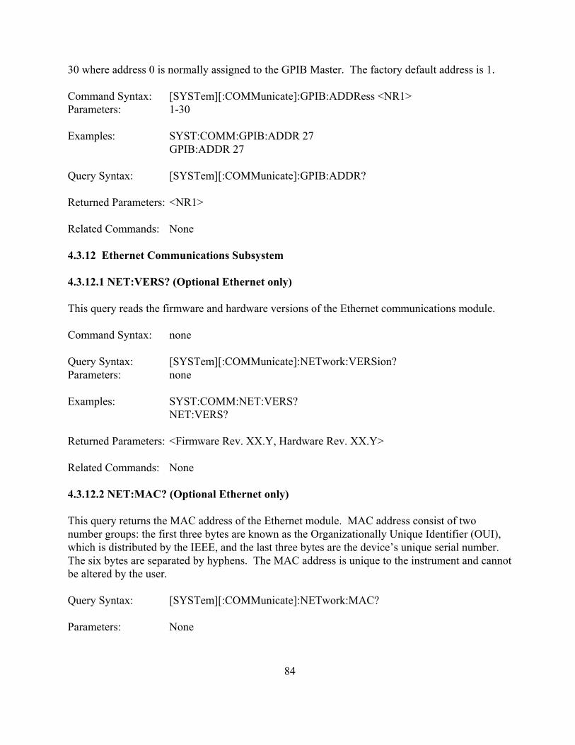
30 where address 0 is normally assigned to the GPIB Master. The factory default address is 1.
Command Syntax: [SYSTem][:COMMunicate]:GPIB:ADDRess <NR1>Parameters: 1-30
Examples: SYST:COMM:GPIB:ADDR 27GPIB:ADDR 27
Query Syntax: [SYSTem][:COMMunicate]:GPIB:ADDR?
Returned Parameters: <NR1>
Related Commands: None
4.3.12 Ethernet Communications Subsystem
4.3.12.1 NET:VERS? (Optional Ethernet only) This query reads the firmware and hardware versions of the Ethernet communications module.
Command Syntax: none
Query Syntax: [SYSTem][:COMMunicate]:NETwork:VERSion? Parameters: none
Examples: SYST:COMM:NET:VERS?NET:VERS?
Returned Parameters: <Firmware Rev. XX.Y, Hardware Rev. XX.Y>
Related Commands: None
4.3.12.2 NET:MAC? (Optional Ethernet only)
This query returns the MAC address of the Ethernet module. MAC address consist of twonumber groups: the first three bytes are known as the Organizationally Unique Identifier (OUI),which is distributed by the IEEE, and the last three bytes are the device’s unique serial number. The six bytes are separated by hyphens. The MAC address is unique to the instrument and cannotbe altered by the user.
Query Syntax: [SYSTem][:COMMunicate]:NETwork:MAC?
Parameters: None
84

Examples: SYST:COMM:NET:MAC?NET:MAC?
Returned Parameters: <XX-XX-XX-YY-YY-YY>
Related Commands: NET:ADDR, NET:GATE, NET:SUBN, NET:PORT, NET:HOST, NET:DHCP
4.3.12.3 NET:SER? (Optional Ethernet only)
This command sets the serial number of the Ethernet module. The serial number is an integerranging from 1 to 16777215 and cannot be altered by the user.
Query Syntax: [SYSTem][:COMMunicate]:NETwork:SER?
Parameters: None
Examples: SYST:COMM:NET:SER?NET:SER?
Returned Parameters: <integer>
Related Commands: none
4.3.12.4 NET:ADDR (Optional Ethernet only)
This command sets the static address of the Ethernet module of the power supply. The factory default address setting is 192.168.1.100.
Command Syntax: [SYSTem][:COMMunicate]:NETwork:ADDRess <string> Parameters: IP address is represented with 4 bytes each having a range of 0-255
separated by dots
Examples: SYSTem:COMM:NET:ADDR 192.168.10.2NET:ADDR 192.168.10.2
Query Syntax: [SYSTem][:COMMunicate]:NETwork:ADDR?
Returned Parameters: <string>
Related Commands: NET:MAC, NET:GATE, NET:SUBN, NET:PORT, NET:HOST, NET:DHCP
4.3.12.5 NET:GATE (Optional Ethernet only)
85
This command sets the Gateway IP address of the Ethernet module of the power supply. Thefactory default Gateway IP setting is 192.168.1.1.
Command Syntax: [SYSTem][:COMMunicate]:NETwork:GATE <string> Parameters: Gateway IP address is represented with 4 bytes each having a range of 0-
255 separated by dots
Examples: SYSTem:COMM:NET:GATE 192.168.10.2NET:GATE 192.168.10.2
Query Syntax: [SYSTem][:COMMunicate]:NETwork:GATE?
Returned Parameters: <string>
Related Commands: NET:MAC, NET: ADDR, NET:SUBN, NET:PORT, NET:HOST, NET:DHCP
4.3.12.6 NET:SUBN (Optional Ethernet only)
This command sets the subnet IP Mask address of the Ethernet module of the power supply. The factory subnet mask setting is 255.255.255.0.
Command Syntax: [SYSTem][:COMMunicate]:NETwork:SUBNet<string> Parameters: IP mask address is represented with 4 bytes each having a range of 0-255
separated by dots
Examples: SYSTem:COMM:NET:SUBNet 255.255.255.128NET: SUBNet 255.255.255.128
Query Syntax: [SYSTem][:COMMunicate]:NETwork:SUBNet?
Returned Parameters: <string>
Related Commands: NET:MAC, NET: ADDR, NET:GATE, NET:PORT, NET:HOST, NET:DHCP
4.3.12.7 NET:PORT (Optional Ethernet only)
This command sets the Socket (Port) of the Ethernet module of the power supply. The factory default port setting is 50505. The factory recommends port values greater than 49151to avoid conflicts with registered Ethernet port functions.
Command Syntax: [SYSTem][:COMMunicate]:NETwork:PORT <integer > Parameters: 16-bit socket number (1 to 65,535)
86

Examples: SYSTem:COMM:NET: PORT 50505NET: PORT 50505
Query Syntax: [SYSTem][:COMMunicate]:NETwork:PORT?
Returned Parameters: <integer>
Related Commands: NET:MAC, NET: ADDR, NET:GATE, NET:SUBN, NET:HOST, NET:DHCP
4.3.12.8 NET:HOST? (Optional Ethernet only)
This query reads the host name of the Ethernet communications module.
Command Syntax: none
Query Syntax: [SYSTem][:COMMunicate]:NETwork:HOSTname? Parameters: none
Examples: SYST:COMM:NET:HOST?NET:HOST?
Returned Parameters: <string>
Related Commands: NET:MAC, NET: ADDR, NET:SUBN, NET:PORT, NET:DHCP
4.3.12.9 NET:DHCP (Optional Ethernet only) This command sets the DHCP operating mode of the Ethernet module. If DHCP is set to 1, themodule will allow its IP address to be automatically set by the DHCP server on the network. If DHCP is set to 0, the IP address is set according to Section 4.3.12.4. The factory DHCP setting is1.
Command Syntax: [SYSTem][:COMMunicate]:NETwork:DHCP <NR1>Parameters: 0 = DHCP Off; 1= DHCP On
Examples: SYST:COMM:NET:DHCP 0NET:DHCP 1
Query Syntax: [SYSTem][:COMMunicate]:NETwork:DHCP?
Returned Parameters: <NR1>
87

Related Commands: NET:MAC, NET: ADDR, NET:GATE, NET:SUBN, NET:PORT,NET:HOST
4.3.13 Recall Subsystem (MSD Series only)
The recall subsystem sets the current memory location of the power supply. In remote mode, 100(0 - 99) memory locations are available for programming. In local mode, the 10 (0 - 9) memorylocations are available for programming.
The query command, MEM?, returns the current memory location.
Command Syntax: [RECall]:MEMory <NR1>
Examples: REC:MEM 10MEM 99
Query Syntax: RECall:MEMory?
Returned Parameters: <NR1>
Related Commands: *RCL, *SAV
4.3.14 Modulation Subsystem (MSD Series only)
The Modulation Subsystem adjusts the output voltage or current according to the voltagemeasured on the external analog input, pin 25 of JS1, named VMOD. This signal has an allowedinput range 0-10 V. Modulation requires the power supply to be configured for remote mode. Rotary mode control or external program mode control cannot be used with this command
4.3.14.1 MOD:TYPE:SEL
This command is composed of two comma separated, modulation parameters. The firstparameter, control input, defines whether the modulation table adjusts output voltage or outputcurrent. When the control input is set to 1, VMOD selects the modulation table to adjust outputvoltage. When control input is set to 2, VMOD selects the modulation table adjust to outputcurrent. Setting the control input to the default value of 0, disables the modulation function. Information on programming the lookup table is provided in Section 4.3.14.2.
The second command parameter, type, defines the expression for modulating output voltage orcurrent. With type set to 0, table data points are used in a multiplying expression. With type setto 1, table data points are used in an addition expression. The alternatives for modulationexpressions are illustrated in Table 4.3.
88

The choice of using type 0 or type 1 modulation depends on the application. Only one set pointcan be modulated at any given time. The query command returns two comma separatedparameters, the control input followed by the algorithm.
Table 4.3 MODULATION FUNCTION SUBSYSTEM PARAMETERS
ControlInput
Type
0 1
(default) 0 disabled disabled
1 Vom=Vo×Mod Vom=Vo+Mod
2 Iom=Io×Mod Iom=Io+Mod
Notes:1) Vom is the adjusted output voltage as a function of the modulation operator2) Iom is the adjusted output current as a function of the modulation operator3) Vo is the output voltage as a function of input set point voltage4) Io is the output current as a function of set point current 5) Mod is a value derived from a lookup table as determined by an analog interfacesignal,VMOD. Mod is made continuous using a piecewise linear approximation algorithm. Intype 0 modulation, Mod is unitless. In type 1 modulation, Mod represents either a voltage orcurrent for control inputs 1 or 2, respectively.
Command Syntax: MODulation:TYPE:SELect <NR1>[,<NR1>]
Examples: MOD:TYPE:SEL 1,0MOD:TYPE:SEL 2,1MODulation:TYPE:SELect 0
Query Syntax: MODulation:TYPE:SELect?
Returned Parameters: <NR1>,<NR1>
Related Commands: None
4.3.14.2 MOD:TABL
This command programs the user defined modulation table described in Section 4.3.14.1. Thefeature allows the user to program nonlinear output voltage and current profiles to fit theirapplication needs, such as source emulation or output adjustments with respect to an externalsensor.
The lookup table contains 4 columns and up to 50 rows; it stores an output profile as a function ofthe analog input voltage applied to terminal 25 of JS1, VMOD. As shown in Table 4.4, the first
89

column stores the table row and the second column sets an analog input VMOD. The thirdcolumn store the Mod value associated with VMOD for that table row.
The fourth column of the lookup table, Loc, defines whether the table is stored in an active ortemporary location. Certain applications may need to transition between different tables whilethe power supply is still running. For example, emulation of solar panel’s voltage/currentcharacteristics requires continuous external data acquisition along with quick and smooth tableloading . The modulation subsystem provides two storage locations, Loc 0 or 1, to help improvetable loading performance. With Loc set to 0, data will be stored to the Active Table, the tablewhich is actively applied to the modulation function. With Loc set to 1, data will be stored to theCache Table, the table intended to be accessed in the next in the profile. During the power oncycle, modulation tables stored in EPROM are copied into volatile RAM. Additional SCPIcommands related to data storage and table transfers are described in Sections 4.3.14.3 and4.3.14.4.
Modulation linearly interpolates between data points to form a piecewise-linear curve. Eachcolumn has to have data in an acceptable range. All tables less than 50 rows must be terminatedwith a VMOD value of 9999. Mod values at and past a row with VMOD of 9999 does not affectmodulation.
TABLE 4.4 MODULATION TABLE PARAMETERS
Column
1 2 3 4
Description Row VMOD Mod Loc
Acceptable Range 1 to 50 0.0 TO 10.0 -1000.0 to 1000.0 0 to 1
While the table will store any value within the acceptable range, the power supply is limited by itsoutput voltage and current specifications. For example, when using type 1 modulation,MOD:TYPE:SEL 1,1, a user can store a Mod value of -1000, but the power supply will onlyoutput a voltage down to 0 V.
Modulation points are read with two comma separated parameters, formatted as:Row, Loc. The query will return four parameters, formatted in the same way as the save tablecommand above.
Command Syntax: MOD:TABL <NR1>(<NRf>,<NRf>,<NR1>)
Examples: MOD:TABL 12(0.13, 1.6, 1)MODulation:TABLe 20(2.0, 15.002, 0)MOD:TABL 13(1.5, -1.29, 0)MOD:TABL 14(9999, 0, 1)
90

Query Syntax: MOD:TABL? <NR1>,<NR1>
Returned Parameters: <NR1>(<NRf>,<NRf>,<NR1>)
Related Commands: None
4.3.14.3 MOD:SAVE
This command copies the Active Table in RAM to a non-volatile, EEPROM memory. The ActiveTable, which is stored in RAM, loses its data on power down cycles. This command allows thisdata to be recovered at the power on cycle.
Command Syntax: MOD:SAVEMODulation:TABLe:SAVE
Examples: MOD:SAVE
Query Syntax: None
Returned Parameters: None
Related Commands: MOD:TABL:LOAD
4.3.14.4 MOD:TABL:LOAD This command copies all data stored in the Cache Table to the Active Table. The commandprovides two optional parameters for initiating the activate set points for voltage and current. Thecommand lets users quickly load tables and simultaneous change the power supply’s outputoperating point.
Command Syntax: MOD:TABL:LOAD [<NRf>, <NRf>] Examples: MOD:TABL:LOAD
MODulation:TABLe:LOAD MODulation:TABL:LOAD 93.4, 30.3
Query Syntax: None
Returned Parameters: None
4.3.15 SCPI Data Formats
All data programmed to or returned from the power supply are formatted in ASCII. The data maybe structured as numerical or character string as described in Table 4.5.
91

Table 4.5 SCPI DATA FORMATSFORMAT DESCRIPTON EXAMPLES<> Null, no data.<NR1> Digits with an implied decimal point assumed at the right of
the least-significant digit. -2730273
<NR2> Digits with an explicit decimal point. 273..0273
<NR3> Digits with an explicit decimal point and an exponent 2.73E+2273.0E-2
<NRf> Extended format that includes <NR1>, <NR2> and <NR3>. 273-273.02.73E2
<NRf+> Expanded decimal format that includes <NRf>, MIN, andMAX
273-2732.73E2MINMAX
4.4 IEEE-488 Event Processing
All of the SCPI subsystem commands in the previous section can be initiated using RS232,optional IEEE-488, or optional Ethernet communications.The IEEE-488 standard defines a method for status reporting. As illustrated in figure 4.1, themethod uses the IEEE-488.1 Status Byte (STB). Three bits of this byte are defined as: MasterStatus Summary (MSS) Bit, Event Status Bit (ESB), and Message Available (MAV) Bit.
The Master Status Summary (MSS) is an unlatched bit. When the Status Byte Register is readusing a Status Byte Register query (discussed in Section 4.5.4), bit 6 will be 1 if there are anyconditions requiring service.
The STB is masked by the Service Request Enable Register (SRE) to allow the user to maskspecific or all events from setting the MSS bit to 1. The MSS bit is obtained by logical OR’ingthe bits of the enabled Status Byte Register.
The Event Status Bit (ESB) is set when one of the events defined in the Event Status Register(ESR) (see Table 4.6) has occurred. As shown in figure 4.2 and like the STB, the ESR is maskedby the Event Status Enable Register (ESE) to allow the user to mask specific or all events fromsetting the ESB to 1.
The Message AVailable (MAV) bit is set to 1 when a message is available in the output buffer.
4.5 IEEE-488 Standard Commands
The following sections describe the IEEE-488 Standard Commands.
92

4.5.1 Clear
Thiscommandclears allstatusregister(ESR,STB anderrorqueue).
CommandSyntax:
*CLS <>
QuerySyntax:
none
Returned Parameters: none
Related Commands: *RST
4.5.2 Read Event Status Register
This query reads the Event Status Register (ESR). After reading the ESR, the register is cleared. The bit configuration of the ESR is the same as the Event Status Enable Register (*ESE). Thereturn parameter is weighted as shown in Table 4.6.
The Power On Bit (PON) is set every time the power supply is reset. It can be used to detect apower outage or power supply reset.
93
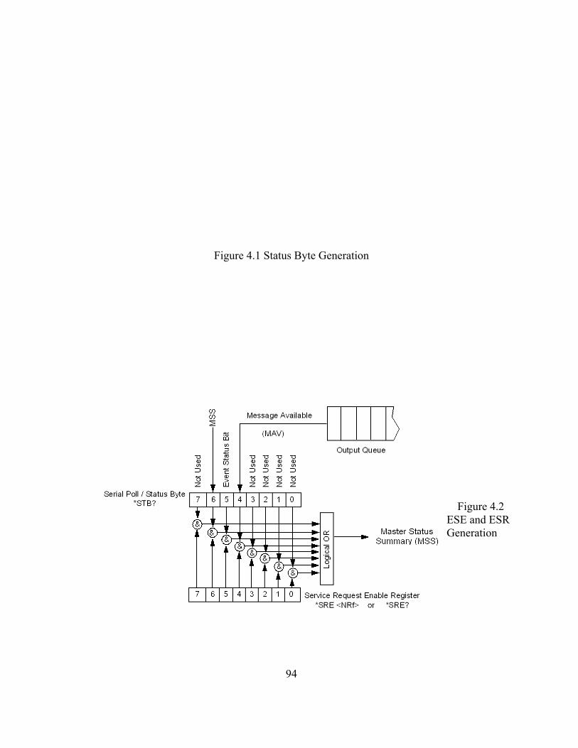
Figure 4.1 Status Byte Generation
Figure 4.2ESE and ESRGeneration
94

Query Syntax: *ESR?
Example: *ESR?
Return Parameter: <NR1> (Register value)
Related Commands: *CLS, *ESE, *ESE?
Table 4.6 EVENT STATUS REGISTER BIT POS. WEIGHT ABBREVIATION DESCRIPTION0 1 OPC Operation Complete1 2 NU Not Used2 4 QYE Query Error3 8 DDE Device Dependent Error4 16 EXE Execution Error5 32 CME Command Error6 64 NU Not Used7 128 PON Power On Event, 1 after power on
4.5.3 Read and Set Event Status Enable Register
This command programs the Event Status Enable Register (ESE). The programming determineswhich events of the Event Status Register (ESR) set the Event Status Bit (ESB) of the Status ByteRegister (STB). A "1" in the bit position enables the corresponding event. All of the enabledevents of the ESE are logically OR’d to cause the ESB of the STB to be set.
Command Syntax: *ESE <NR1> Example: *ESE 255
Query Syntax: *ESE?
Return Parameter: <NR1>
Related Commands: *ESR?, *STB?
4.5.4 Read Status Byte Register
This query reads the Status Byte Register (STB), defined in Table 4.7, which contains the MasterStatus Summary (MSS) bit, Event Status (ESB) bit, and the Message Available (MAV) bit. Unlike reading ESR, the STB is not cleared after it is read. The MAV bit is cleared at power onor by *CLS.
Query Syntax: *STB?
95

Example: *STB?
Return Parameter: <NR1> (Register value)
Related Commands: *ESR?, *ESE
Table 4.7 STATUS BYTE REGISTERBIT POS. WEIGHT ABBREVIATION DESCRIPTION
0 1 NU Not Used1 2 NU Not Used2 4 NU Not Used3 8 NU Not Used4 16 MAV Message Available5 32 ESB Event Status Bit6 64 MSS Master Summary 7 128 NU Not Used
4.5.5 Read and Set Service Request Enable Register
This command sets the Service Request Enable Register (SRE). This register, defined in Table4.8, determines which bits from the Status Byte Register (see *STB for its bit configuration) areallowed to set the Master Status Summary (MSS) Bit. A 1 in any SRE bit position enables thecorresponding Status Byte Register bit. All Status Byte Register enabled bits are then logicallyOR’d and placed in bit 6 of the Status Byte Register. When *SRE is cleared (by programming itwith 0), the power supply cannot generate a service request to the controller.
Command Syntax: *SRE <NR1>
Example: *SRE 20
Query Syntax: *SRE?
Return Parameter: <NR1> (Register value)
Related Commands: *ESE, *ESR
Table 4.8 SERVICE REQUEST ENABLE REGISTERBIT POS. WEIGHT ABBREVIATION DESCRIPTION0 1 NU Not Used1 2 NU Not Used2 4 NU Not Used3 8 NU Not Used4 16 MAV Message Available
96

5 32 ESB Event Status Bit6 64 NU Not Used7 128 NU Not Used
4.5.6 Read Model Number, Part Number, and Serial Number
This query requests the power supply to identify itself. It returns a string composed of threefields separated by commas.
Query Syntax: *IDN?
Returned Parameters: Company Name, Power Supply Model, S/N (string format)
Example: Magna-Power Electronics, Inc., MSD16-1800, S/N: 1161-0361
Related Commands: CALibrate:IDN (Refer to Section 4.3.9.1, Calibrate Subsystem, forinformation on configuring the MS Series power supply.)
4.5.7 Save
This command stores the present state of the power supply at the specified location in memory. Data can be saved in 100 memory locations. The following power supply parameters are storedby *SAV:
VOLT[:LEV][:IMM]CURR[:LEV][:IMM] VOLT:PROT[:LEV]CURR:PROT[:LEV]PER
Command Syntax: *SAV <NR1>Parameters: 0 - 99
Example: *SAV 1
Query Syntax: None
Related Commands; *RCL, MEM
4.5.8 Recall
This command restores the power supply to a state that was previously stored in memory locationwith a *SAV command. The *RCL command can recall data in 100 memory locations. Thefollowing parameters are recalled:
97

VOLT[:LEV][:IMM]CURR[:LEV][:IMM] VOLT:PROT[:LEV]CURR:PROT[:LEV]PER
The *RCL command forces an ABORt command before resetting any parameters. ABOR cancelsany trigger actions presently in progress and sets INIT:CONT to OFF.
At power turn-on, recall is commanded at the memory location prior to turn-off state.
Command Syntax: *RCL <NR1>Parameters: 0 - 99
Example: *RCL 1
Query Syntax: None
Related Commands; *RST, *SAV
4.5.9 Reset
This command resets the power supply to factory default states as defined below.
OUTP[:STAT] OFFCURR[:LEV][:IMM] 0 CURR[:LEV]:TRIG 0 VOLT[:LEV][:IMM] 0 VOLT[:LEV]:TRIG 0 PER 0INIT:CONT OFFVOLT:PROT[:LEV] 110% of MAXCURR:PROT[:LEV] 110% of MAX
*RST also forces an ABORt command.
Command Syntax: *RST <>
Query Syntax: None
Related Commands: None
4.6 Error Messages
98
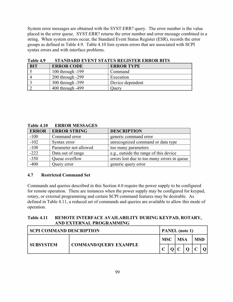
System error messages are obtained with the SYST:ERR? query. The error number is the valueplaced in the error queue. SYST:ERR? returns the error number and error message combined in astring. When system errors occur, the Standard Event Status Register (ESR), records the errorgroups as defined in Table 4.9. Table 4.10 lists system errors that are associated with SCPIsyntax errors and with interface problems.
Table 4.9 STANDARD EVENT STATUS REGISTER ERROR BITSBIT ERROR CODE ERROR TYPE5 100 through -199 Command4 200 through -299 Execution3 300 through -399 Device dependent2 400 through -499 Query
Table 4.10 ERROR MESSAGESERROR ERROR STRING DESCRIPTION-100 Command error generic command error-102 Syntax error unrecognized command or data type-108 Parameter not allowed too many parameters-222 Data out of range e.g., outside the range of this device-350 Queue overflow errors lost due to too many errors in queue-400 Query error generic query error
4.7 Restricted Command Set
Commands and queries described in this Section 4.0 require the power supply to be configuredfor remote operation. There are instances when the power supply may be configured for keypad,rotary, or external programming and certain SCPI command features may be desirable. Asdefined in Table 4.11, a reduced set of commands and queries are available to allow this mode ofoperation.
Table 4.11 REMOTE INTERFACE AVAILABILITY DURING KEYPAD, ROTARY,AND EXTERNAL PROGRAMMING
SCPI COMMAND DESCRIPTION PANEL (note 1)
SUBSYSTEM COMMAND/QUERY EXAMPLEMSC MSA MSD
C Q C Q C Q
99

Source VOLT and VOLT:TRIGVOLT:PROTCURR and CURR:TRIGCURR:PROTPER (MSD Series only)
!!!!
!!!!
!
!
!!!!!
Measure MEAS:VOLT?MEAS:CURR?
!!
!!
!!
System SYST:VERS?SYST:ERR?
!!
!!
!!
Status STAT:OPER:COND?STAT:QUES:COND?
!!
!!
!!
Output OUTP?OUTP:ARM (MSD Series only)OUTP:STARTOUTP:STOPOUTP:PROT:CLE
!!!
!!
!!!
!!
!!!!
!!
Abort ABOR
Trigger TRIG:IMM
Initiate INIT:IMM and INIT:CONT ! ! !
Calibrate CAL:IDNCAL:PASSCAL:POTCAL:SCAL:VOLTCAL:SCAL:CURRCAL:DEFCAL:STOP
!
!!!
!!!!
!
!!!
Configure REM:SENSCONT:INTCONT:EXTINTESETPT
!!!!!
!!!!!
!!!!!
!!!!!
!!!!!
!!!!!
GPIBCommunications
GPIB:VER?GPIB:ADDR !
!! !
!! !
!!
100

EthernetCommunications
NET:VER?NET:MAC?NET:SER?NET:ADDRNET:GATENET:SUBNNET:PORTNET:HOSTNET:DHCP
!!!!!!!!
!!!!!!!!!
!!!!!!!!
!!!!!!!!!
!!!!!!!!
!!!!!!!!!
Recall(MSD Series only)
MEM !
Modulation(MSD Series only)
MOD:TYPE:SELMOD:TABL
!!
!!
IEEE Standard *CLS*ESR?*ESE *STB?*SRE?*IDN?*SAV*RCL*RST
!
!
!
!!!!!
!
!
!
!!!!!
!
!!
!!!!!
Notes:1. C: command, Q: query.
101

5.0 INTERFACING USING THE REMOTE INTERFACE SOFTWARE
The Remote Interface Software is shipped with MS Series power supplies. The software providesthe user with a quick method to operate a Magna-Power Electronics’ power supply undercomputer control. The Remote Interface Software has six windows: the Virtual Control Panel,Command Panel, Register Panel, Calibration Panel, Firmware Panel, and Modulation Panel. TheVirtual Control Panel emulates the front panel of the MS Series power supply, the Commandpanel programs and reads SCPI commands with user friendly buttons, the Register Panelprograms and reads registers, the Calibration Panel enables calibration of the digitalpotentiometers, the Firmware Panel enables the program stored internal to the power supply to beupgraded, and the Modulation Panel eases programming of modulation parameters.
5.1 Application Setup
To communicate with the power supply, the front panel version, type of communication, address and/or port need to be specified. The options are:
1. Power supply series: select A Version for MSA Series, D Version for MSD Series, and A Version for MSC Series power supplies,
2. Communications interface: RS232, RS485, optional GPIB (IEEE-488), optionalTCP/IP (Ethernet), simulated, or others depending on future developments. Figure5.1 displays the Applications Setup Window. Address requirements are:
a. RS232: port.b. RS485: address and port, 1-30.c. IEEE-488: address, 1-30.d. Ethernet: address and port.
Figure 5.2 illustrates the communications setup for GPIB communications. The address specifiesthe desired device on the bus to establish communications. To locate a particular device or to seta new address, press Find Device or Change Device’s setting, respectively. The Find Devicespanel displays all devices on the bus that are available for communications. The Change Device’sSetting allows the address of the particular device to be changed. When changing a device’saddress, the address in the Communication Setup will also change allowing continuedcommunications. These panels are illustrated in figure 5.3. Similar panels are displayed forEthernet, RS232, and RS485 communications.
5.2 Virtual Control Panel
Figure 5.4 and 5.5 illustrate the Virtual Control Panels for D Version and A Version models,respectively. The Virtual Control Panel emulates front panel commands and the means to controlC Version models.
To make keypad entries for D Version models, type the entry using the computer keyboard and
102

Figure 5.1 Configuration setup
Figure 5.2 GPIB communications setup
103

(a) (b)
Figure 5.3 Find devices and (b) change device’s GPIB settings
press enter at the bottom right side of the window. Other than the keypad, operation is virtuallyidentical to the front panel commands described in Section 3.1.
5.3 Command Panel
The Command Panel is illustrated in figure 5.6. The Command Panel is organized into threegroups: commands and queries requiring data input, commands with only command syntax, andcommands with only query syntax. The Output frame on the right of the window echoes theSCPI command used to communicate with the power supply. This feature provides the user withthe proper syntax for each command. The Output frame can be cleared or saved to a file bypressing the clear button or the save to file button. Commands in gray are not accessible with theparticular configuration.
5.4 Register Panel
The Register Panel is illustrated in figure 5.7. The Register Panel graphically represents the sixinternal registers of the power supply. Register functions, as covered in the previous Chapter, arebriefly summarized below:1. Operation register (oper): indicates the power supply’s current operational state. The
register is unlatched and is described in Section 4.3.4.12. Questionable register (ques): indicates the current state of power supply alarms. The
register is unlatched and is described in Section 4.3.4.2.3. Status Byte register (STB): indicates communications error messages. The register is
latched and is described in Section 4.5.4.4. Service Request Enable register (SRE): a mask register for the STB. The register is
described in Section 4.5.5.5. Standard Event Status register (ESR): a latched register which is similar to STB except it
provides more details. The register is described in Section 4.5.2.
104
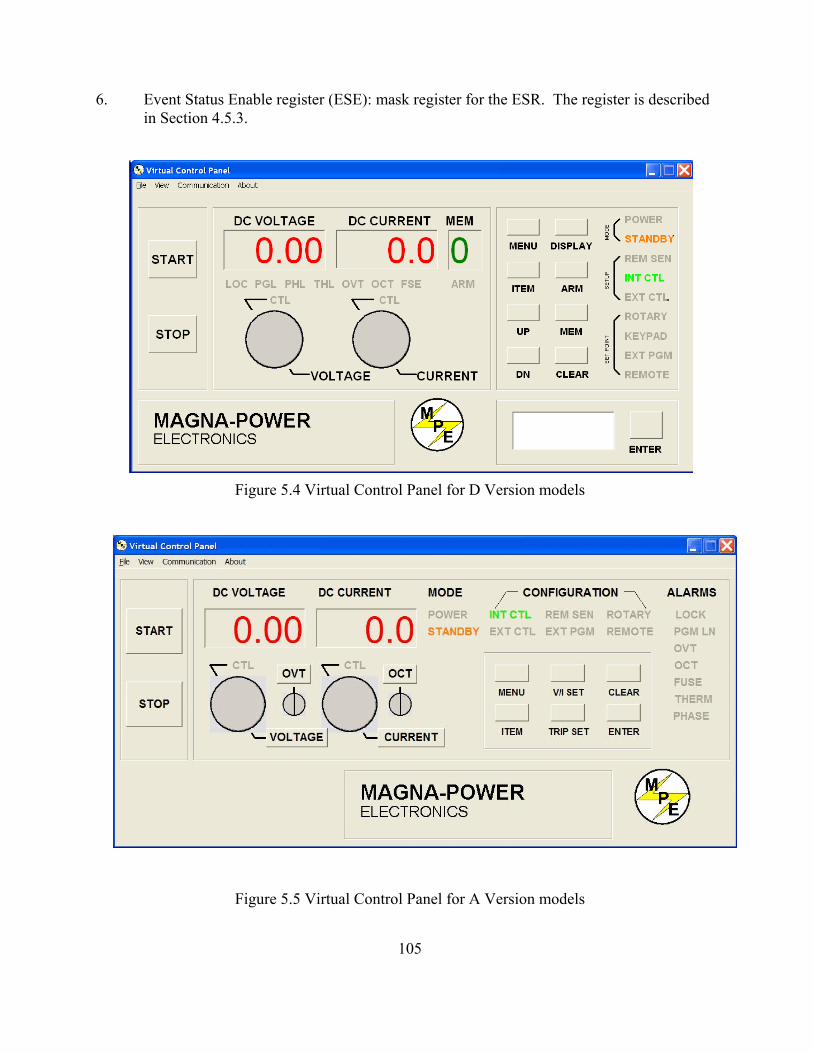
6. Event Status Enable register (ESE): mask register for the ESR. The register is describedin Section 4.5.3.
Figure 5.4 Virtual Control Panel for D Version models
Figure 5.5 Virtual Control Panel for A Version models
105

Figure 5.6 Command Panel
As illustrated in the Register panel, each column denotes a register value, and the rows, markedby the leftmost column, are the bit positions. The get button at the column heading will acquirethe respective register value for the power supply. The labels in each column indicate themeaning ofeach bit. For example, bit 5 in the Ques column will light if fuse alarm is activated. The maskregisters, SRE and ESE, can be modified via the set button in their column heading. Enter thevalue in the “Enter Value in Selected Format” frame, and then press the set button. If no errorsoccur, then the new value will appear after the get button is pressed. The Results frame displaysthe returned register value in decimal, hex and binary formats. The “Enter Value in SelectedFormat” frame allows the user to specify the format for data entry.
The Output frame shows all communications with the power supply. The Output frame can becleared or saved to a file by pressing the clear button or the save to file button.
5.5 Calibration Panel
The Calibration Panel, illustrated in figure 5.8, provides easy access and programmability for thedigital potentiometers. The Calibration Panel is password protected. To enable changes, enter1234 for the password and then press the adjacent set button. The five digital potentiometers canaccept numbers from 0 to 255. Further commands include setting the potentiometer to the factory
106

default setting and end calibration procedure. The Output frame shows all communications withthe power supply. The Output frame can be cleared or saved to a file by pressing the clear buttonor the save to file button.
Voltage Scale and Current Scale are not available to the user. These are factory specificcommands that require an alternate password to access.
5.6 Firmware Panel
The Firmware Panel is illustrated in figure 5.9. The Firmware Panel enables the program storedinternal to the power supply to be upgraded. The factory recommends that firmware upgrades beperformed only if there is an operational problem with the power supply.
The following steps list the procedure for upgrading the firmware:1. Turn the power supply off.2. Connect a RS232 cable between a serial port on a computer and connector JS3 on the
power supply.3. Press the select button and choose the file to be loaded.4. Press the start button. The Status frame will display “Initiating.”5. Turn on the power supply. If the supply is not turned on within 10 seconds, “Time Out”
will be displayed in the Status frame indicating communications is lost.
During the process of upgrading the firmware, the front panel of the power supply will remainblank. After communications is established, the Status frame will initially display “Erasing” andthe Current Address frame will display the address in memory being erased. After the entirememory is erased, the Status frame will display “Loading ” and the Current Address frame willdisplay the address in memory being loaded. The Status frame will display “Finished” and thefront panel display will return to normal after the memory is reprogrammed..
Pressing the stop button will terminate execution at any time.
5.7 Modulation Panel (D Version front panels only)
The Modulation Panel is illustrated in figure 5.10. The Modulation Panel enables a user to setand view the modulation settings as described in Section 4.3.14. The modulation settings consistof control input, modulation type (multiplication or addition), table row, modulation voltageinput, and modulation factor. The Modulation Panel provides the form to program a linear orpiece-wise linear lookup table for the selected modulation type. The lookup table can have amaximum of 50 data points. The modulation voltage input, VMOD, must be entered in ascendingorder. For lookup tables with less than 50 data points, VMOD must be terminated with 9999. Any data entered for modulation factor on the terminating row is ignored. The Output frame onthe right of the window displays all of the communications with the power supply. The Outputframe can be cleared or saved to a file by pressing the clear button or the save to file button.
107

Figure 5.7 Register Panel
Figure 5.8 Calibration Panel
108

Figure 5.9 Firmware Panel
Figure 5.10 Modulation Panel for Version D models only
109
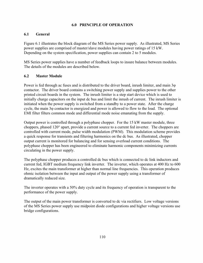
6.0 PRINCIPLE OF OPERATION
6.1 General
Figure 6.1 illustrates the block diagram of the MS Series power supply. As illustrated, MS Seriespower supplies are comprised of master/slave modules having power ratings of 15 kW. Depending on the system specification, power supplies can contain 2 to 5 modules.
MS Series power supplies have a number of feedback loops to insure balance between modules.The details of the modules are described below.
6.2 Master Module
Power is fed through ac fuses and is distributed to the driver board, inrush limiter, and main 3φcontactor. The driver board contains a switching power supply and supplies power to the otherprinted circuit boards in the system. The inrush limiter is a step start device which is used toinitially charge capacitors on the input dc bus and limit the inrush of current. The inrush limiter isinitiated when the power supply is switched from a standby to a power state. After the chargecycle, the main 3φ contactor is energized and power is allowed to flow to the load. The optionalEMI filter filters common mode and differential mode noise emanating from the supply.
Output power is controlled through a polyphase chopper. For the 15 kW master module, threechoppers, phased 120° apart, provide a current source to a current fed inverter. The choppers arecontrolled with current mode, pulse width modulation (PWM). This modulation scheme providesa quick response for transients and filtering harmonics on the dc bus. As illustrated, chopperoutput current is monitored for balancing and for sensing overload current conditions. Thepolyphase chopper has been engineered to eliminate harmonic components minimizing currentscirculating in the power supply.
The polyphase chopper produces a controlled dc bus which is connected to dc link inductors andcurrent fed, IGBT medium frequency link inverter. The inverter, which operates at 400 Hz to 600Hz, excites the main transformer at higher than normal line frequencies. This operation producesohmic isolation between the input and output of the power supply using a transformer ofdramatically reduced size.
The inverter operates with a 50% duty cycle and its frequency of operation is transparent to theperformance of the power supply.
The output of the main power transformer is converted to dc via rectifiers. Low voltage versionsof the MS Series power supply use midpoint diode configurations and higher voltage versions usebridge configurations.
110

Figure 6.1 Block diagram
CONTACTOR3-PHASE
CHOPPERPOLYPHASE
TRANSFORMERPOWER
BOARDGATEDRIVER
BOARDCONTROL
RECTIFIERS PIE FILTER
DISPLAYBOARD
INTERFACEASS'Y
DC VOLTAGE& CURRENT208/480 V
3-PHASE
CURRENT FEDINVERTERINDUCTORS
DC LINK
DETECTORFUSE/PHASE
EMI FILTERFUSES
RECTIFIER3-PHASE
INRUSHLIMITER
DC LINKINDUCTORSEMI FILTER
FUSES 3-PHASERECTIFIERCONTACTOR
3-PHASE POLYPHASECHOPPER INVERTER
CURRENT FEDTRANSFORMER
POWERRECTIFIERS PIE FILTER
LIMITERINRUSH
++
MASTER
SLAVE
111

The dc output voltage is filtered with a pie section filter. This, in combination with the dc link inductors, form a double stage inductive capacitive (LC) filter.
The gate driver board supports a synchronized modulation scheme which integrates powersemiconductor switching of the switching power supply, polyphase chopper, and mediumfrequency link inverter.
The fuse/phase detector senses input line voltage on each phase and continuity of each fuse. Upon detection of a problem, the control board is signaled to shutdown the system. The controlboard, which is referenced to earth ground, contains optically isolated amplifiers to sense outputvoltage and current. This circuitry allows the output to be referenced ±1000 Vdc above earthground.
The display board contains light-emitting diodes for displaying diagnostic conditions andprovides an interface for meters and switches.
6.3 Slave Module
The slave module is very similar to the master module. The choppers are controlled with currentmode, pulse width modulation (PWM) from signals derived from the master module gate driverboard. The second set of chopper signals are displaced 60° from the first set of chopper signals inthe master module. Together, a 20 kW system has six chopper modules phased 60° apart.
The medium frequency link inverter in the slave module uses the same driver signals as themaster module.
For systems greater than 30 kW, additional gate driver boards are required. One board is requiredfor every 30 kW of power processed.
The slave module’s diagnostic features are coordinated with the master module to provide highperformance with virtually any combination of modules. Balance between chopper currents isinsured by independent sampling and feedback control. Power supply, chopper, and invertermodules are synchronized to avoid instabilities at different operating points., and invertermodules are synchronized to avoid instabilities at different operating points.
112

7.0 MAINTENANCE AND TROUBLE SHOOTING
7.1 General
The MS Series power supplies consist of a multistage power processing system. Because of itscomplexity, it is highly recommended that all repairs be performed by the factory or qualifiedpower supply technician. Before attempting maintenance or repair, the technician should befamiliar with the components of the systems and the theory of operation. Some basic testequipment is also necessary: source of ac power, means of loading the power supply, dc voltmeterwith accuracy and resolution better than the unit specifications, and an oscilloscope. The chart inSection 7.2 should aid in finding operational problems.
Caution: When servicing the power supply, dangerous voltage levels exist. All ac and dc capacitors should be discharged. Be especially careful ofperson and equipment when measuring primary circuitry since this is at linepotential.
7.2 Trouble Shooting Guide
1. Fuse F1, F2, or F3 blows when the power supply is turned on. Power supply has a shorton the primary side.a. Check diode bridge DB1.b. Check for failed power semiconductor on the Chopper Module.c. Check for isolation to ground on the input side of the power supply.
2. Over current trips and power supply cannot be reset. An auxiliary over current detectorlimits input dc link current. Exceeding safe levels will cause an over current diagnosticcondition that cannot be reset.a. Restart the supply. Transient voltages on the input voltage could have caused the
problem.b. Check diodes D1 through D4 on the secondary side of transformer T1.c. Check for a shorted winding on transformer T1.d. Check for failed IGBT’s in the Chopper and Inverter Modules.
3. Unit goes to high output immediately after starting.a. Check for loose connectors internal to the power supply.
4. High ripple voltage.a. Check the mains voltage for balance and magnitude.
113

7.3 Calibration
7.3.1 Control Board
The control board contains digital potentiometers for fine adjustments of the reference andfeedback amplifiers. These potentiometers may be adjusted by using the front panel controlsdescribed in Section 3.1.1.4 and 3.1.2.3 for the MSD and MSA Series power supplies,respectively. These potentiometers can also be adjusted by using the Calibration Panel of theRemote Interface Software described in Section 5.5.
7.3.1.1 Reference Amplifier Calibration
Connect a voltmeter between terminal 6 of JS1 (positive) and terminal 1 of JS1 (negative). Withonly the control power applied, adjust potentiometer P5 for a 2.5006 V.
7.3.1.2 Voltage Feedback Amplifier Calibration
Place a dc voltmeter across the output terminals of the power supply and place a second dcvoltmeter to monitor VO2, the voltage between terminal 5 of JS1 (positive) and terminal 1 of JS1(negative). Set the load to 50% rated output current at full scale voltage. With only the control power applied, adjust potentiometer P2 for 0.000 V at VO2. Using thekeypad or the RS232 remote interface, set the output voltage to 50% full scale output. Turn onthe power supply and adjust potentiometer P1 until the output voltage matches the set pointvoltage. Now set the output voltage to its full scale rating and measure the output voltage. Adjust potentiometer P1 to equally divide the error between the half scale set point and the fullscale point.
7.3.1.3 Current Feedback Amplifier Calibration
Place a dc ammeter in series with the load of the power supply and place a dc voltmeter tomonitor IO2, the voltage between terminal 24 of JS1 (positive) and terminal 1 of JS1 (negative). Set the load to 100% rated output current at 90 % full scale voltage.
With only the control power applied, adjust potentiometer P4 for 0.000 V at IO2. Using thekeypad or the RS232 remote interface, set the output current to 50% full scale output. Turn onthe power supply and adjust potentiometer P3 until the output current matches the set pointcurrent. Now set the output current to its full scale rating and measure the output current. Adjustpotentiometer P3 to equally divide the error between the half scale set point and the full scalepoint.
7.3.2 Driver Board
The driver board contains two potentiometers which are used to set under voltage and over
114

current protection in the polyphase chopper circuitry. These potentiometer do not normally needadjustment in the field.
7.3.2.1 Over Current Protection
Over current protection should only be calibrated after consultation with the factory.
Gross misadjustment can cause chopper and inverter failure.
Place a dc voltmeter between test point TP6 (positive) and test point TP7 (negative). With onlythe control power applied, adjust potentiometer P1 to 6.00 V.
7.3.2.2 Under Voltage Protection
Under voltage protection should only be calibrated after consultation with the factory.
Gross misadjustment can cause chopper and inverter failure.
Connect the power supply to an adjustable ac source and connect an ac voltmeter to monitor thevoltage applied to the input terminals. Tests can be performed under no load conditions. Set theac source to rated voltage. Turn the control power, press the start switch, and a adust the outputvoltage to 10% full scale output. Decrease the ac source to a value between 75% to 82% of ratedvoltage. Adjust potentiometer P2 until the output drops to zero; the transition will be abrupt.
Decrease the ac source to a value between 72% to 79% of rated voltage. The main contactorshould turn off.
115

8.0 APPLICATIONS
8.1 General
MS Series power supplies deploy several powerful programming functions that enhanceperformance for user specific applications. While the possibilities are endless, a few examplesare presented in this chapter to demonstrate the internal capabilities of the power supply. All ofthese examples can be further expanded by operating the unit under computer control.
8.2 Power Waveform Generator
MSD Series power supplies can be programmed to operate as a power waveform generator. Referring to Section 3.1.1.5, each memory state needs to be programmed for the desired voltageor current for a specific time period. An example of a power waveform generator and itscorresponding programming values are shown in figure 8.1 and Table 8.1, respectfully. In thisparticular example, the voltage set point is changed in 10 second intervals while the current, overvoltage trip, and over current trip are kept constant. To make the power supply repeat the voltageramp, a time period of 9998 is entered for step 9. The programming causes the memory state tojump back to 0 after completing step 8. To start the ramp generator, set the power supply tomemory state 0, press the arm key, and then the start key. Press the stop key to terminateoperation.
Figure 8.1 Sawtooth output voltage
116

Table 8.1 RAMP GENERATOR SEQUENTIAL STEP PROGRAM
MemoryVoltageSet (V)
CurrentSet (A)
OverVoltage
Trip (V)
OverCurrentTrip (A)
Period(S)
0123456789
05
1015202530354040
200200200200200200200200200200
55555555555555555555
220220220220220220220220220220
101010101010101010
9998
8.3 Leadless Remote Sensing
Remote sensing is used to improve the degradation of regulation which will occur at the loadwhen the voltage drop in the connecting wires is appreciable. Remote sensing, as described inSection 3.3, requires an pair of wires to be connected between the output of the power supply andthe desired point of load regulation. Remote sensing can be accomplished, without the use of theadditional sense leads, by calculating the voltage drop in the output leads and adjusting the outputvoltage accordingly.
To establish leadless remote sensing, connect terminal 24 of JS1 to terminal 25 of JS1, set themodulation control parameter to voltage control, and set the modulation type to 1. Figure 8.2illustrates the hardware connection and Section 4.3.14 describes application of the modulationsubsystem. With this configuration, output voltage will increase or decrease with output currentas defined by the modulation table. By programming a positive slope into the modulation table,output voltage and voltage drop due to lead loss can be made to cancel. For an installation wherethere is a 2% drop in voltage at full scale current, the modulation table should be programmedaccording to Table 8.2. For row 3 in the modulation table, VMOD is given the value 9999 tosignify the last entry.
8.4 Photovoltaic Cell Simulator
Modulation enables the power supply to emulate different sources: such as batteries, fuel cells,photovoltaic arrays, etc. To simulate a photovoltaic array, connect terminal 24 of JS1 to terminal25 of JS1, set the modulation control parameter to voltage control, and set the modulation type to0. Figure 8.3 illustrates the programmed piece-wise linear approximation for a typicalphotovoltaic array and Table 8.3 defines the associated piece-wise linear modulation table toemulate that array. For this example, a MSD125-53 power supply was chosen for the powersource.
117

Figure 8.2 Leadless remote sensing
Figure 8.3 IV characteristics for atypical photovoltaic array
Table 8.2 MODULATION TABLEFOR LEADLESS REMOTE SENSING(TYPE 1)
Row VMOD(Vdc) Vos(MOD)
123
0.02.0
9999
0.000.040.00
Table 8.3 MODULATION TABLE FOR
IO2 24
REF GND
25
P/O JS1
VMOD
1,2,20
118

EMULATION OF A PHOTOVOLTAIC ARRAY (TYPE 0)
Row VMOD(Vdc) Mod(VMOD)
Vo(Vdc)
Io(Adc)
123456789
10111213
0.0002.0853.6454.6905.2105.4155.7306.0406.2506.4606.6656.7709999
1.0000.9520.9050.8570.8090.7620.7140.6660.6190.5710.4760.0000.000
1051009590858075706560500
0.010.017.522.525.026.027.529.030.031.032.032.5
Note: Set the program voltage to 105 V.
8.5 Battery Charger
Figure 8.4 illustrates a temperature compensated battery charger for applications with lead acidbatteries. Diode D1, placed between the power supply and battery, blocks current from flowingfrom the battery to the power supply. This eliminates any loading on the battery when the powersupply is off, but more importantly, prevents the battery from charging the power supply’s outputcapacitors. With deployment of diode D1, remote sensing should be applied across the batteryterminals to compensate for the diode drop. By setting the voltage and current to the bulk chargevoltage and maximum charge current, the power supply will initially charge the batteries incurrent mode control and then automatically crossover to voltage mode control when the batteriesreach the desired set point. The power supply can be programmed for time dependent, sequentialstep operation, see Section 3.1.1.5, to equalize and float charge the batteries after bulk charging. Equalization is generally not required for every charge cycle. Table 8.4 illustrates the differentcharging steps and Table 8.5 provides the recommended charging voltage per cell for differentbattery technologies.
Diode D1 with associated remote sense connections can be avoided with application of the high-slew rate option. As compared to standard MS Series models, the high-slew rate option has lessoutput capacitance and less loading on the battery when the power supply is off. Appendix 8.6discusses the benefits of this option.
119

Caution: All battery parameters presented in this section are guidelines and theuser should refer to and use manufacturer’s specifications in any batterycharging application.
A temperature detector can be applied to the modulation input to adjust the set point voltage withtemperature. In this example, the temperature sensor, integrated circuit U1, is a two terminaldevice that produces a current proportional to temperature. This device, AD592, is manufacturedby Analog Devices. The temperature detector, place between terminals 21 and 25 of connectorJS1, produces a temperature dependent current. This current produces a voltage drop across the10 K input impedance at the modulation input. Table 8.6 provides the recommended chargevoltage deviation per cell as a function of temperature.
Figure 8.4 Battery charger with temperature compensation
1,2,20
VMOD
P/O JS1
25
REF GND
24IO2
R1
+5
3.32 KTYPICAL
AD592U1
+
-
VO1REM-
VO1REM+
VS-
VS+
1
2
JS2
B1
VO-
VO+
MULTIPLEXER
D1
120

Table 8.7 defines the modulation parameters for applying temperature compensation to a standard12 V lead acid battery using a MSD16-200 power supply. The modulation control parametershould be set to voltage control and modulation type should be set to 1.
Table 8.4 CHARGING PROGRAMMING AND CHARACTERISTICS
PARAMETER
STEP 1BULK
CHARGE
STEP 2ABSORPTION
CHARGE
STEP 3EQUALIZATION
CHARGE
STEP 4FLOAT
CHARGE
MEMORY STEPVOLTAGE SETCURRENT SETOVTOCTPERIOD
0Vbc
Imbc105%•Vbc
110%•Imbc6 hours
0Vbc
Imbc105%•Vbc
110%•Imbc6 hours
1 VecImec
105%•Vec110%•Imec
1 hours
2 VfcImec
105%•Vfc110%•Imec
MODE OFCONTROL
Current Voltage Current/Voltage Voltage
Notes:Vbc: Bulk charge voltageVec: Equalize charge voltageVfc: Float charge voltageImbc: Maximum bulk charge current (25% of AH capacity maximum)Imec: Maximum equalization charge current (10% of AH capacity maximum)
Table 8.5 BATTERY CHARGING PER CELL
CHARGING VOLTAGE RANGE
BATTERY TYPE BULKVbc (Vdc)
EQUALIZEVec (Vdc)
FLOATVfc (Vdc)
WET STANDARD (Sb/Sb) DEEP CYCLEWET LOW MAINTENANCE (Sb/Ca)WET MAINTENANCE FREE (Ca/Ca)VRLA AGMVRLA GEL CELL
2.417 - 2.4672.400 - 2.433
2.4672.400 - 2.4672.350 - 2.400
2.567 - 2.6672.517 - 2.7332.583 - 2.717
NANA
2.167 - 2.2002.183 - 2.2002.183 - 2.2332.200 - 2.3002.200 - 2.300
Notes:1) Ca: Calcium, Sb: Antimony2) VRLA: Valve regulated lead acid3) AGM: Sealed absorbed Glass Mat, also known as started electrolyte
121

Table 8.6 BATTERY CHARGING TEMPERATURECOMPENSATION PER CELL
ELECTROLYTETEMPERATURE
(°F)
ELECTROLYTETEMPERATURE
(°C)
DEVIATION INCHARGEVOLTAGE (Vdc)
+/- RANGE
0102030405060708090
100110120130140150160
-17.8-12.2-6.7-1.14.4
10.015.621.126.732.237.843.348.954.460.065.671.1
++++++++
--------
.224 - .264
.196 - .231
.168 - .198
.140 - .165
.112 - .132
.084 - .099
.056 - .066
.028 - .0330.000
.028 - .033
.056 - .066
.084 - .099
.112 - .132
.140 - .165
.168 - .198
.196 - .231
.224 - .264
Notes:1) Deviation is 2.80 to 3.30 mV/°F/cell
Table 8.7 MODULATION TABLE FOR A TEMPERATURE COMPENSATED BATTERYCHARGER (TYPE 1)
Row VMOD(Vdc) Mod(VMOD)
Vo(Vdc)
12345
0.0000.5130.6921.2059999
0.1830.183
-0.183-0.1830.000
16.1016.10
-13.18-13.18
0
Note: Set the program voltage to 14.64V.
122

8.6 High-Slew Rate Option
The standard output stage of MS Series power supplies has been designed to provide thelowest possible output ripple voltage within the constraints of available components, size,and cost. Part of the output stage consists of a bank of aluminum electrolytic capacitorswhich has the desired electrical properties to provide this function. These componentsrequire bleed resistors to discharge any voltage when the power supply has no load and isdisabled. While the presence of these components and the resulting performance arenormally industry accepted, there are applications where lower output capacitance andlower loss bleed resistors are extremely desirable and higher ripple voltage is acceptable. To meet this need, a high-slew rate option is available which has an output stage consistingof low capacitance film and aluminum electrolytic capacitors and lower loss bleedresistors. Applications for the high-slew rate option include battery charging, photovoltaicemulation, power waveform generation, and medium speed power pulsing. Theseapplications all benefit from higher bandwidth and in many case, can tolerate increasedripple voltage.
The high rate-slew rate option in MS Series power supplies solves several problemsinherent in switching power supply design. Rapid voltage transitions require internalelectronics to supply the energy to charge and discharge output capacitors. Peak currentsinternal to the power supply define slew rate; utilizing less capacitance enables voltagetransitions in shorter time periods. Additionally, less capacitance reduces requirements fordischarge demands during open circuit conditions.
For battery charger applications, output capacitance and internal bleed resistors presentitself as a load to the connecting batteries. One common practice is to use a series diode toblock reverse current flow with the sacrifice of increased cost and lower efficiency. Thehigh slew rate option, with its lower output capacitance and lower loss bleed resistors,enables direct connection to batteries without series blocking diodes.
For photovoltaic emulation applications, higher bandwidth and lower output capacitanceenable improved performance with higher speed, maximum power tracker algorithms. Maximum power tracker circuitry deviates the operating point of photovoltaic arrays todetermine maximum power output. Slow responding emulation sources can present aproblem when the speed of the algorithm exceeds that of the source. Furthermore, withlower output capacitance, changes in the operating point and transients, caused by shortingthe solar inverter input, produce lower unwanted input currents.
The high-slew rate option enables a MS Series power supply to operate as a low frequency,power pulse generator. With the special capacitors selected for this option, it is possible tosuperimpose waveforms or produce a medium speed pulse on top of the dc output andexpect normal capacitor life. It is important to note that the power supply output is singlequadrant; that is, the output voltage or current cannot reverse.
123

APPENDIX A IEEE-488 COMMUNICATIONS
MS Series power supplies are available with an optional IEEE-488 (GPIB) interface. When specified at time of order, an IEEE-488 interface module is installed to make asecond UART port available for communications. With two UART ports available, RS232and IEEE-488, the one first receiving communications after power on is the port that isactivated. Once activated, the other UART port cannot be recognized unless there has beena period of inactivity for 5 minutes. After this period, a new UART port can be recognizedby sending communications.
An IVI-COM Driver is included with the installation CD and is available for downloadfrom Magna-Power Electronics’ web page. The driver allows the power supply tocommunicate through many different programming languages. The driver handles the low-level bus protocols, simplifying automation development. It supports TCP/IP, GPIB andRS232 using standard VISA resource descriptors. For additional documentation anddetails on using the IVI-COM driver, see the driver's included help file (MPEIVI.chm).
A.1 IEEE-488 Communications using the Remote Interface Software
Chapter 5.0 describes application of the Remote Interface Software which is shipped withMS Series power supplies. This software provides the user with a quick method to operatea Magna-Power Electronics’ power supply under computer control. The software can beconfigured for a number of communication interfaces; IEEE-488 is included as one ofthese interfaces.
To use the Remote Interface Software with optional IEEE-488 communications, theaddress, 1 to 30, defined in the Remote Interface Software and the address encoded in thepower supply must match. Address 0 is normally assigned to the GPIB master The defaultaddress is 1, but if the address is unknown, press Find Device in the Communication Setupmenu. The routine scans all the devices on the bus providing their addresses andidentifications. Select the desired device and press OK; this automatically changes theaddress in the Communication Setup. The same result can be achieved with a double clickon the desired device. After communications is established, the address of the device maybe changed by pressing Change Device’s Settings.
A.2 IEEE-488 Communications with MAX
National Instruments offers Measurement and Automation Explorer (MAX), a GraphicalUser Interface, as a terminal emulation program for configuring an Interchangeable VirtualInstrument (IVI). MAX is usually installed with one of National Instrument’s ApplicationDevelopment Environments such as LabVIEW, Measurement Studio, or with hardwareproduct drivers such as NI-488.2 and NI-DAQ.
124

To operate the power supply with MAX, the instrument must first be located forcommunications. The following steps describe this procedure.
1. Run the MAX application program.2. In the Configuration window, press the + sign to the left of Devices and Interfaces
to view the installed devices. 3. If there is more than one IEEE-488 (GPIB) device listed, then select the correct
GPIB device.4. Press Scan for Instruments on the menu bar and wait several seconds.5. At least one instrument should appear under the GPIB controller. If no instruments
appear, then refer to Section A.1 to verify the correct setup.6. On the menu bar, press Communicate with Instrument. The NI-488.2
Communicator dialog box should appear.7. In the NI-488.2 Communicator dialog box, press the Configure EOS button. The
Termination Method dialog box should appear.a. Select the option Send EOI at end of Write.b. Enter 0 into th EOS byte.c. Press OK.
125

APPENDIX B ETHERNET COMMUNICATIONS
XR Series power supplies are available with an optional Ethernet interface. Whenspecified at time of order, an Ethernet interface module is installed to make a secondUART port available for communications. With two UART ports available, RS232 andEthernet, the one first receiving communications after power on is the port that is activated. Once activated, the other UART port cannot be recognized unless there has been a periodof inactivity for 5 minutes. After this period, a new UART port can be recognized bysending communications.
Ethernet communications can be made though the Remote Interface Software, a terminalemulation programs like Microsoft Windows (tm) HyperTerminal Program, or through acomputer’s web page browser. In the latter case, software, programmed into the Ethernetinterface module, allows the power supply to be recognized and to communicate directlywith the computer without the need for additional programs stored in the computer.
An IVI-COM Driver is included with the installation CD and is available for downloadfrom the Magna-Power Electronics’ web page. The driver allows the power supply tocommunicate through many different programming languages. The driver handles the low-level bus protocols simplifying automation development. It supports TCP/IP, GPIB, andRS232 using standard VISA resource descriptors. For additional documentation anddetails on using the IVI-COM driver, see the driver's included help file (MPEIVI.chm).
B.1 Ethernet Communications using the Remote Interface Software
Chapter 5.0 describes application of the Remote Interface Software which is shipped withXR Series power supplies. This software provides the user with a quick method to operatea Magna-Power Electronics’ power supply under computer control. The software can beconfigured for a number of communication interfaces; Ethernet is included as one of theseinterfaces.
To use the Remote Interface Software with optional Ethernet communications, the addressparameters in the Remote Interface Software and that encoded in the power supply mustmatch. The factory default for DHCP is 1 (on) allowing the IP address to be automaticallyset by the DHCP server on the network. If DHCP is set to 0 (off), the power supply’saddress can be manually set. See Section 4.3.12 for setting address parameters. If DHCPis off and the address is unknown, the device can be located by following one of theprocedures described in Section B.3.2.3.
B.2 Ethernet Communications using HyperTerminal
The following procedure outlines using Microsoft Windows (tm) HyperTerminal Programto communicate using the Ethernet communications.
126

1. Start the HyperTerminal application and when prompted select “TCP/IP(Winsock)” in the “Connect using” list box.
2. Insert the recorded IP address in the “Host address” text box and port number in the“Port number” text box.
3. Click the “OK” button.4. Set the following properties for HyperTerminal’s ASCII setup:
a. Send line ends with line feeds.b. Echo typed characters locally.c. Append line feeds to incoming line ends.
5. Type “*IDN?” in the input window and press enter. The identification of theinstrument should appear.
B.3 Ethernet Communications using a Web Page Browser
The Ethernet interface has an embedded web server that allows the user to view and changethe module's network settings and provides basic control of the power supply. Magna-Power Electronics’ optional Ethernet option is LXI Class C compliant under LXI StandardRevision 1.2.
B.3.1 Connectivity
When the Ethernet module is configured for DHCP, but the DHCP server cannot belocated, the module falls back to an Auto-IP configuration. The device then automaticallyselects an IP address from 169.254.x.x subnet as described in RFC 3927 (Request forComments 3927 - Dynamic Configuration of IPv4 Link-Local Addresses). This routine isthe same as that used with operating systems such as Microsoft Windows. This allows theuser to use the Ethernet interface in the absence of a DHCP server.
The LAN status LED, located at the rear of the power supply, provides LAN fault anddevice identification as defined as follows:
1. On – Normal Operation. The device has a properly configured IP address and thenetwork cable is connected,
2. Flashing – Device Identify. The LXI Device Identification function was enabledvia the Instrument Identification web page. This can help the user to quickly locatethe unit and distinguish it from similar devices.
3. Off – LAN Fault. The device is experiencing one or more of the following LANfault conditions: failure to acquire a valid IP address, detection of a duplicate IPaddress on the network, failure to renew an already acquired DHCP lease, or theLAN cable is disconnected.
The LAN Reset button provides a way to reset the LAN configuration password and to setthe device back to DHCP/Auto-IP mode. To activate the LAN Reset function, ensure thepower supply is on and in standby mode. Hold down the LAN Reset button for
127

approximately 4 seconds. Observe that the LAN LED rapidly flashes and after 4 seconds,release the LAN Reset button. The LAN configuration password will be reset to blank andthe module will be set to DHCP/Auto-IP enabled.
B.3.2 Discovery
The Ethernet module supports the VXI-11 discovery protocol allowing the device to bediscovered on the network by software such as National Instruments' Measurement &Automation Explorer, Agilent Connection Expert, or the Remote Interface Softwaresupplied with the power supply.
B.3.2.1 Discovery using NI Measurement & Automation Explorer
To access discovery with NI Measurement & Automation Explorer, the NI-VISA add-onmodule must be installed along with the standard software package. Start NI Measurement& Automation Explorer, right-click on Devices and Interfaces, and then select "CreateNew…" Select "VISA TCP/IP Resource" from the list. Click Next and then select Auto-detect of LAN Instrument. Click Next and the software will scan the local network forVXI devices and display them for configuration for further usage with NI-VISA andrelated software.
B.3.2.2 Discovery using Agilent Connection Expert
To access discovery with Agilent Connection Expert, start Agilent Connection Expert. Select your computer's LAN interface and then click the Add Instrument button at the topof the screen. The software will scan the local network for VXI devices and display themfor configuration for further use with Agilent VISA compatible software.
B.3.2.3 Discovery using the Remote Interface Software
If DHCP is off and the address is unknown, the device can be located using the RemoteInterface Software supplied with the power supply. To access discovery, press FindDevice in the Communication Setup menu. The routine scans all the devices on thenetwork and provides their addresses and identifications. Select the desired device andpress OK; this automatically changes the address in the Communication Setup. The sameresult can be achieved with a double click on the desired device. After communications isestablished, the address of the device may be changed by pressing Change Device’sSettings.
B.3.3 Web Interface
To access the web server, first determine the module's IP address via one of the discoverymethods described in Section B.3.2. Alternatively, if the host computer supports NetBIOSover TCP/IP, you may use the device's NetBIOS name instead of the IP address.
128

Open a WC3 compliant web browser such as Microsoft Internet Explorer, Firefox, orOpera to http://[ipaddress]/ or http://[name]/. The instrument information screen will bedisplayed as shown in figure B.1. This figure provides the basic information about theconfiguration and allows the user to enable or disable the LXI Identification. Click EnableIdentify or Disable Identify to change the state of the LXI Identification. When LXIIdentification is enabled, the LAN LED on the back of the power supply unit will blink. This can help the user to quickly locate the power supply and distinguish it from similardevices.
To change the Ethernet interface's network settings, click the Configure tab in the upperright. The browser will prompt for a username and password if you have not authenticatedthe device already. To authenticate, enter admin for the username and leave the passwordfield blank. The instrument configuration screen, figure B.2, will appear. This pageenables the user to change the Hostname (which corresponds to the NetBIOS name), thedescription, password, and TCP/IP configuration. After changes to the configuration aremade, click the Save Config button. The configuration will be saved, the Ethernet interfacewill reboot and instructions, shown in figure B.3, will be displayed for reconnecting to theinterface.
Web control of the power supply requires Adobe Flash Player which is available fordownload from http://get.adobe.com/flashplayer/. To control the power supply, click theControl tab in the upper right. The browser may prompt for a username and password ifyou have not authenticated the device already. To authenticate, enter admin for theusername and leave the password field blank. The power supply’s control panel, figureB.4, will be displayed. The screen displays the same status information as the front panelof the power supply and allows the user to control and read voltage, current, over voltagetrip, over current trip, mode of operation, and diagnostics. Like the front panel, adiagnostic condition can be cleared using the clear button. Only one user can control thepower supply at a time with the Remote Interface Software or the web interface.
129

Figure B.1 Information Panel
Figure B.2 Configure Panel
130

Figure B.3 Reboot in Progress Panel
Figure B.4 Web Control Panel
131

APPENDIX C USB COMMUNICATIONS
The optional Edgeport/1 USB Expansion Module transparently transforms a USB port to aCOM port.
The Edgeport/1 Windows drivers installs a virtual COM port in the Device Manager of theoperating system. This in turn will allow communications with the MS Series power supplyin the same manner as a device connected to the COM port on a PC. The USB portbecomes transparent to the serial device and the software running on the PC.
C.1 Edgeport/1 Setup
Before installing this optional equipment, the manufacturer recommends that you firstcommission the system using the manual controls on the front panel of the power supply.
To connect the Edgeport/1 USB Expansion Module to the MS Series power supply,proceed as follows:
1. Connect the USB cable between a USB port on the computer and the Edgeport/1Expansion module. This cable is supplied with the Edgeport/1 USB ExpansionModule.
2. If required, install the drivers for the Edgeport/1 USB Expansion Module asdescribed in the Installation Guide.
3. Connect a standard, straight-through, 9-conductor, serial extension cable betweenconnector JS3 on the power supply and the serial port on the Edgeport/1 USBExpansion Module. This cable is supplied with the MS Series power supply.
4. Establish RS232 communications by configuring the power supply for remoteoperation using the front panel commands described in Section 3.1.1.3 and 3.1.2.2for MSD and MSC Series power supplies, respectfully.
C.2 Edgeport/1 Communications using the Remote Interface Software
Chapter 5.0 describes application of the Remote Interface Software which is shipped withMS Series power supplies. This software provides the user with a quick method to operatea Magna-Power Electronics’ power supply under computer control. The software can beconfigured for a number of communication interfaces.
To use Remote Interface Software with the Edgeport/1 USB Expansion Module, performthe setup described in previous section and refer to Section 5.1 to configure the softwarefor RS232 communications.
132

APPENDIX D RS485 COMMUNICATIONS
The optional 485DSS to RS232 converter, transparently converts data between two portswith control codes or special commands.
The Model 485DSS, RS485 distributed smart switch, allows multiple addressing of RS232devices. The host computer uses RS485 output to send commands to the networkconsisting of multiple 485DSS devices interfacing to RS232 communications equipment. Each 485DSS device has a unique address that can be set from 0 to 255.
The 485DSS communication parameters are: 9600 baud, no parity, 8 data bits, and 1 stopbit. Once the computer is connected to the RS232 port, the computer’s communicationparameters can be changed to match the RS232 port. There is no delay or buffering of datain the 485DSS.
D.1 485DSS Initial Setup
This section sets up the hardware for the 485DSS module.1. The default address for the 485DSS is 0. To change this address, remove the
module’s cover and locate the DIP switch in the center of the printed circuit board. Set the desired address on the DIP switch using the bit weights associated with eachswitch.
2. Set the 485DSS for either 2-wire or 4-wire communications. Jumper settings areillustrated in figure D.1.
3. For noisy environments, a terminator may be required between the RD(A) andRD(B) lines. To add a terminator, set the termination jumper to IN to the 485DSSat the end of the line.
4. Connect the serial cable from the connector JS3 on the power supply to the485DSS. This requires a male DB9 to female DB25 serial cable.
5. Establish RS232 communications by configuring the power supply for remoteoperation using the front panel commands described in Section 3.1.1.3 and 3.1.2.2for MSD and MSC Series power supplies, respectfully.
D.2 HyperTerminal Setup
This section sets up the Microsoft Windows HyperTerminal for communicating with the485DSS.1. Start the HyperTerminal program in Windows by pressing Start, Programs,
Accessories, Communications, and HyperTerminal.2. In the Connection Description dialog box, type MPE Comm and click the OK
button.3. The Connect To dialog box will then appear. Select the desired COM port.4. The COM Properties dialog box will appear. Set the following parameters:
133

a. Bits per second to 9600.b. Data bits to 8.c. Parity to None.d. Stop Bits to 1.e. Flow control to None.
5. Click the OK button.6. On the menu bar, select File, Properties to open the Properties dialog box.7. Click on the Settings tab, and click the ASCII Setup button.8. On the ASCII Setup dialog box, set the following:
a. Send line ends with line feeds.b. Echo typed characters locally.c. Append line feeds to incoming line ends.
9. Press the OK button to close the ASCII Setup dialog box.10. Press the OK button to close the Properties dialog box.
D.3 485DSS Address Command
A command is required to address each individual 485DSS module. Once addressed, themodule will transparently convert serial data. The address command can only betransmitted at 9600 baud, and if the command is transmitted at any other baud rate, thecommand will be ignored by the 485DSS module. The address command has the followingform: Xoff character, the most significant address character, the least significant addresscharacter, and SOH character. Xoff and SOH require a combination of keys to produce thedesired character in HyperTerminal. Simultaneously pressing the Ctrl key and the S key(Ctrl+S) will produce the Xoff character and simultaneously pressing the Ctrl key and theA key (Ctrl+A) will produce the SOH character. The address range of the 485DSS moduleis from 0 to 255 in decimal or 0 to FF in hex. With HyperTerminal all addresses must beentered as hex.
For an example, to set a 485DSS module with an address of 8F in hex (143 in decimal), theaddress command is: Xoff 8 F SOH. To enter this data into HyperTerminal, the keysequence is Ctrl+S, 8 key, F key and Ctrl+A. If the address is less than 10 hex, a leadingzero is required.
D.4 485DSS Communications using HyperTerminal
This section covers RS485 communications to the power supply using the HyperTerminaland the 485DSS.1. Configure the power supply for remote operation.2. Set the address of the 485DSS module using the procedure in the previous section.
The SEL LED should light.3. On the menu bar in HyperTerminal, press Call, Disconnect.4. On the menu bar in HyperTerminal, press File, Properties to open the Properties
dialog box.
134

5. In the Properties dialog box, press the Configure button to open the COMProperties dialog box. Change the Bits per second to 19200 and then press the OKbutton.
6. Click the OK button on the Properties dialog box.7. On the menu bar, select Call to reestablish communications at the new baud rate.8. Press Enter.9. Type “*IDN?” in the input window and press Enter. The identification string of the
instrument should appear.
135
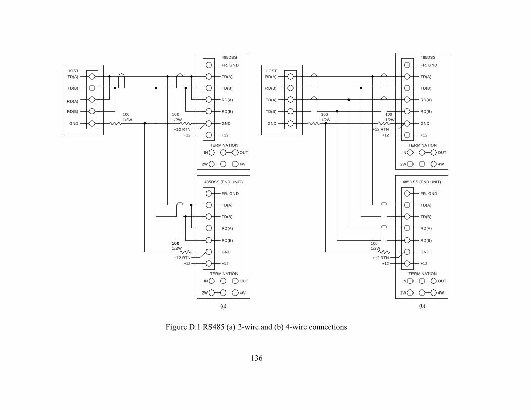
Figure D.1 RS485 (a) 2-wire and (b) 4-wire connections
TD(B)
RD(A)
RD(B)
GND
TD(A)
485DSS
+12
FR. GND
OUTIN
TERMINATION
2W 4W
+12
+12 RTN
HOST
TD(A)
TD(B)
RD(A)
RD(B)
GND
4W2W
TERMINATION
IN OUT
FR. GND
+12
485DSS (END UNIT)
TD(A)
GND
RD(B)
RD(A)
TD(B)
1/2W100
1/2W100
1/2W100 100
1/2W
1001/2W
1001/2W
TD(B)
RD(A)
RD(B)
GND
TD(A)
485DSS (END UNIT)
+12
FR. GND
OUTIN
TERMINATION
2W 4W
GND
RD(B)
RD(A)
TD(B)
TD(A)
HOST
+12 RTN
+12
4W2W
TERMINATION
IN OUT
FR. GND
+12
485DSS
TD(A)
GND
RD(B)
RD(A)
TD(B)
100
+12 RTN
+12
+12 RTN
+12
(a) (b)
136