ms degree in computer engineering university of … · translation pde pte page offset ... •this...
TRANSCRIPT

Topics
• Addressing schemes and software protection models
• Hardware/software protection support
• Kernel access GATEs
• Per-CPU/per-thread memory
• System calls dispatching
• Case study: LINUX (Kernels 2.4/2.6/3.x/..)
MS degree in Computer Engineering
University of Rome Tor Vergata
Lecturer: Francesco Quaglia

Linear addressing
Whatever memory slice available
for software execution (physical vs logical)
Linear address (<offset>)

Segmentation
Segment A
Segment B
Segment C
Address space (a linear one)
address = <seg.id,offset> (es. <A,0x10)

Combining segments in a linear address space
Segment A
Segment B
Segment C
Address specification = <seg.id,offset> (es. <B,offset>)
Need to know where B is
located in the linear address
space (this is the “base” of B)
Then the linear address is
<base+offset>
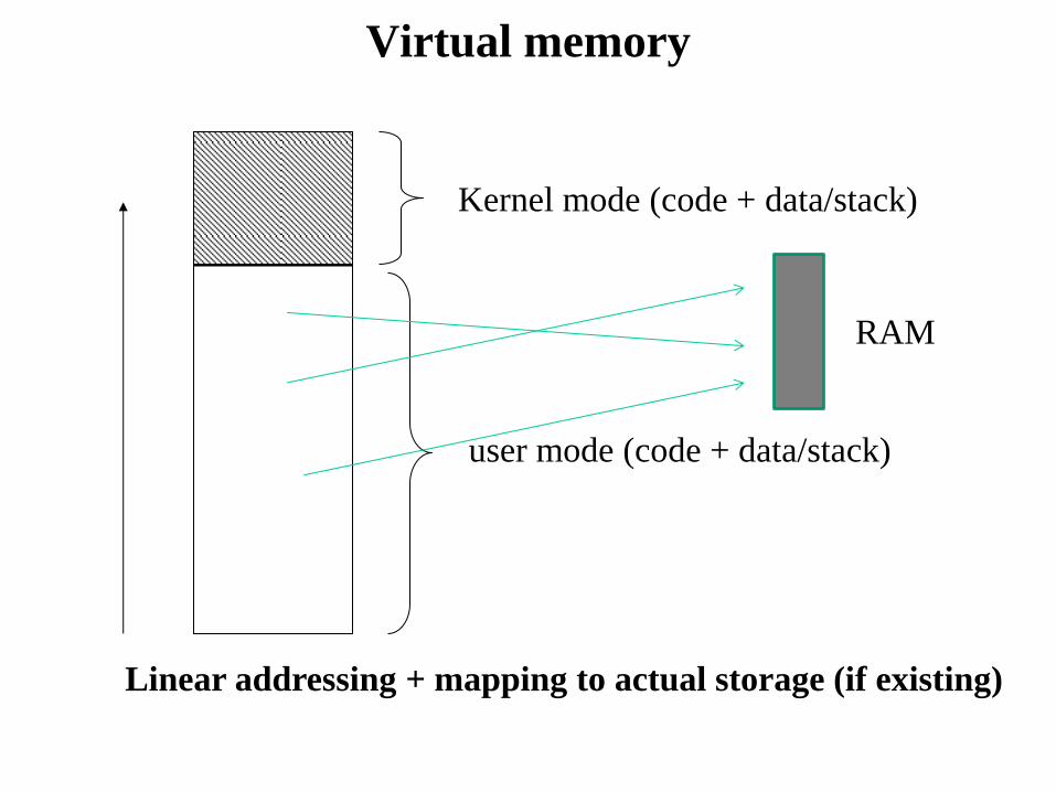
Virtual memory
Kernel mode (code + data/stack)
user mode (code + data/stack)
Linear addressing + mapping to actual storage (if existing)
RAM

Segmentation based addresses
• Code relies on addresses formed by <segment number,
offset>
• If segment numbers are not specified by the machine
instruction, some default segment is used for each target
datum
• Modern processors (system processors) are equipped such in a
way to support segmentation efficiently, in combination with
linear addressing and virtual memory (say paging)
• The whole architecture is therefore requested to handle a
complex address mapping scheme such as
segmented addr linear addr paged addr physical addr
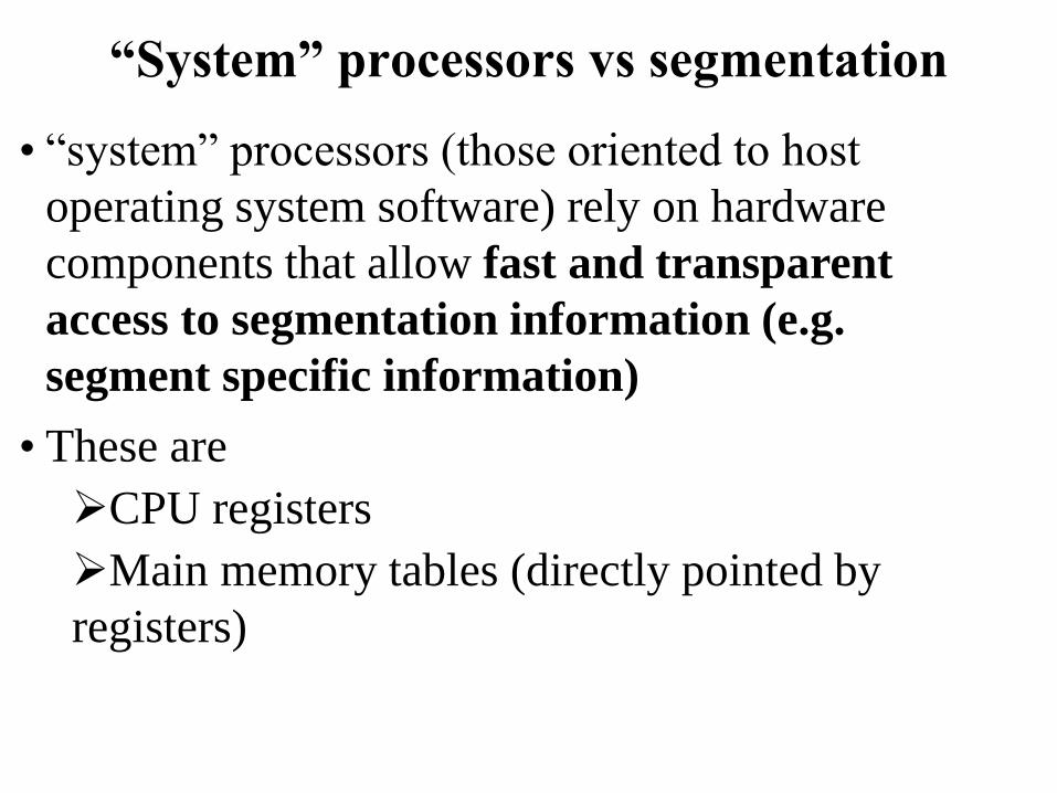
“System” processors vs segmentation
• “system” processors (those oriented to host
operating system software) rely on hardware
components that allow fast and transparent
access to segmentation information (e.g.
segment specific information)
• These are
CPU registers
Main memory tables (directly pointed by
registers)

Segmentation with paging
Segment number offset
HW supported
translation
PDE page offset PTE
• both are logical
addresses
• the offset value may
differ
2-level paging example Determination of the
linear address relying on
<base,offset>

x86 memory access modes
• Real mode
Offers backward compatibility towards 286!!
a 16-bit segment register keeps the target segment ID
16-bit (general) registers keep the segment offset
Targeted addresses are physical, and are computed as
PhysicalAddress = Segment * 16 + Offset
Around 1MB (2^20B) of memory is allowed
Minimal support for separating chunks of memory in the
addressing scheme
No segment specific protection information!!
Not suited for modern software systems!!!

x86 memory access modes
• Protected mode
a 16-bit segment register keeps the target segment ID
(using 13 bits)
32-bit (general) registers keep the segment offset
The base of the segment in linear addressing is kept into a
table in memory
Targeted addresses are linear and are computed as
address = TABLE[segment].base + offset
Up to 4GB of linear (either physical or logical) memory is
allowed
3-bit for control (protection) are kept in the segment
register …. much better for OS software!!!

x86 memory access modes • Long mode (x86-64)
a 16-bit segment register keeps the target segment ID
(using 13 bits)
64-bit (general) registers keep the segment offset
(limited to 48-bit global addressing in canonical form)
The base of the segment in linear addressing is kept into
a table in memory
Targeted addresses are linear and are computed as
address = TABLE[segment].base + offset
Up to 2^48 B (256 TB) of linear memory is allowed
3-bit for control (protection) are kept in the segment
register

x86 segment tables
• The are two table types keeping segments information:
Global Descriptor Table (GDT) and Local Descriptor
Table (LDT)
• Typically GDT and LDT are kept in main memory, and are
directly accessible via pointers maintained by CPU registers
• GDT determines the mapping of linear addresses at least for
kernel mode (namely kernel level segments) ... nowadays it is
the unique used segment table in most operating systems
• LDT determines the mapping of linear addresses for user
mode (namely user level segments), if not done via GDT
• These addresses are then used to access physical memory via
page tables (if paging is activated)

GDT organization
generic
entry
Segment base within
linear addressing
FLAGS
To be composed with
segment-offset upon access
Segment protection and
usage rules

Segmentation vs paging
• Segmentation and paging typically have different targets
• Segmentation is a classical means for protecting code and data
• This protection mechanism is generally based on coarse grain
schemes (in fact, segments may have very large sizes, covering
up to the whole address space for the application)
• Paging (possibly coupled with virtual memory techniques) is
generally employed as a means for improving physical-
memory management efficiency
• Such “efficiency oriented” mechanism is based on a fine-grain
approach, namely it relies on the size of the page frame for the
specific hardware architecture (e.g. 4KB or 2/4MB for x86
architectures)

Segmentation vs multi-cores/multi-threading
• … we know that paging schemes are still able to enforce
protection of memory (via control bits in page-table entries)
• So we may think that segmentation is somehow useless in
modern software systems
• This is a wrong concept, since as we will show segmentation
still plays a central role in multi-core architectures
• It also plays a central role in multi-thread programming
• …… in 1985 paging was already there in the hardware but
Intel further extended the segmentation support (e.g. in the
80386 processor)
• …. although the segmentation logic has been significantly
revised in x86-64 processors

The x86-64 revision
• Registers keeping track of segment IDs (also known as
selectors) are not all managed the same way by firmware on
board of the processor
• For some registers keeping segment IDs (hence for the
corresponding segments in the GDT table) a fixed base of
0x0 is enforced for the segments
• Protection bits in the segment table entries associated with
those segments IDs still work
• For a few registers keeping segment IDs the classical rule
relying on arbitrary base values for the segments is adopted
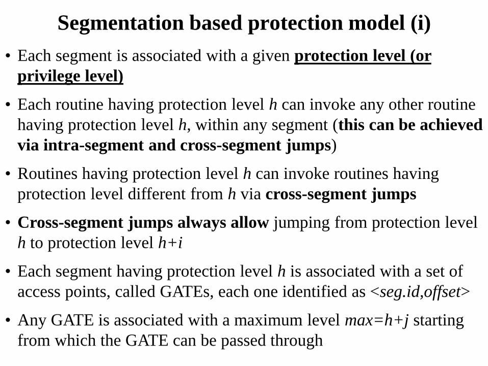
Segmentation based protection model (i)
• Each segment is associated with a given protection level (or
privilege level)
• Each routine having protection level h can invoke any other routine
having protection level h, within any segment (this can be achieved
via intra-segment and cross-segment jumps)
• Routines having protection level h can invoke routines having
protection level different from h via cross-segment jumps
• Cross-segment jumps always allow jumping from protection level
h to protection level h+i
• Each segment having protection level h is associated with a set of
access points, called GATEs, each one identified as <seg.id,offset>
• Any GATE is associated with a maximum level max=h+j starting
from which the GATE can be passed through

Segmentation based protection model (ii)
• If level(S)=h and max(GATE(S))=h+i then segment S
entails a GATE for accessing level h for modules
associated with protection level up to h+i
• Cross-segment jumps deny the access to the destination
if the source operates at protection level greater than the
maximum one associated with the gate
• Overall, cross-segment jumps deny the access to the
destination anytime we do not use a GATE as the
destination entry for the jump

Protection levels and jumps: the ring model
Level 0
Level 1
Level 2
Always admitted
Admitted depending on the max origin level associated with
the target GATE

User routine
Kernel routine A
Kernel routine B
<S1, offset1>
(S1: level 0 – offset1: max = 0)
<S1, offset2>
(S1: level 0 – offset2: max = 3)
S2 (level 2)
Admitted cross-segment
jumps
Non-admitted
cross-segment
jump
An example

Objectives of protection levels
• Denial of uncontrolled access to kernel level modules
• Kernel level access is controlled via specific “entry
points” (the GATEs), which are explicitly used as
destinations for jumps (more generally control flow
variations) originated while running at worse protection
levels
• In conventional operating systems, the entry points are
typically associated with:
interrupt handlers (asynchronous invocations)
software traps (synchronous invocations)

Ring scheme for x86 machines

x86 address composition with segmentation
• An address does not specify the segment ID
directly
• It can specify a Segment-Selector register
• This register keeps information on the actual
segment to which we are accessing
• An example:
<selector-register,displacement>

x86 details on the segmentation support
CS: code segment register
SS: stack segment register
DS: data segment register
ES: data segment register
FS: data segment register
GS: data segment register
CS (Code Segment Register) points to the current segment. The 2 lsb identify the
CPL (Current Privilege Level) for the CPU (from 0 to 3).
SS (Stack Segment Register) points to the segment for the current stack.
DS (Data Segment Register) points to the segment containing static and global data.
For CS RPL is
called CPL
This register is only
writable by control
flow variation
instructions added in
80386

x86 GDT entries (segment descriptors)
Access byte content:
Pr - Present bit. This must be 1 for all valid selectors.
Privl - Privilege, 2 bits. Contains the ring level (0 to 3)
Ex - Executable bit (1 if code in this segment can be executed)
…….
Flags:
Gr - Granularity bit. If 0 the limit is in 1 B blocks (byte granularity),
if 1 the limit is in 4 KB blocks (page granularity)
….
This directly supports
protected mode

Accessing GDT entries
• Given that a segment descriptor is 8 bytes in size, its relative address wihin GDT is computed by multiplying the 13 bits of the index field of segment selector by 8
• E.g, in case GDT is located at address 0x00020000 (value that is kept by the gdtr register) and the index value within segment selector is set to the value 2, the address associated with the segment descriptor is 0x00020000 + (2*8), namely 0x00020010
This is not only a pointer but actually a packed struct
describing positioning and size of the GDT


Example code #include <stdio.h>
struct desc_ptr {
unsigned short size;
unsigned long address;
} __attribute__((packed)) ;
#define store_gdt(ptr) asm volatile("sgdt %0":"=m"(*ptr))
int main (int argc, char**argv){
struct desc_ptr gdtptr;
char v[10];//another way to see 10 bytes packed in memory
store_gdt(&gdtptr);
store_gdt(v);
printf("comparison is %d\n",memcmp(v,&gdtptr,10));
printf("GDTR is at %x - size is %d\n",gdtptr.address, gdtptr.size);
printf("GDTR is at %x - size is %d\n",((struct desc_ptr*)v)->address,
((struct desc_ptr*)v)->size);
}
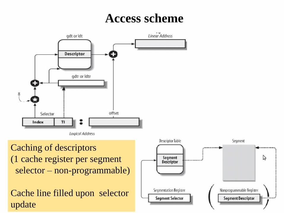
Access scheme
Caching of descriptors
(1 cache register per segment
selector – non-programmable)
Cache line filled upon selector
update

Making explicit usage of segments while coding
#include <stdio.h>
#define load(ptr,var) asm volatile("mov %%ds:(%0), %%rax":"=a" (var):"a" (ptr))
#define store(val,ptr) asm volatile("push %%rbx; mov %0, %%ds:(%1); pop %%rbx“\
::"a" (val), "b" (ptr):)
int main (int argc, char**argv){
unsigned long x = 16;
unsigned long y;
load(&x,y);
printf("variable y has value %u\n",y);
store(y+1,&x);
printf("variable x has value %u\n",x);
}
explicit reference
to the data segment
register (DS)

Code/data segments for LINUX
Can we read/write/execute?
Is the segment present? x86-64 directly forces base to 0x0 for
the corresponding segment registers

x86-64 selector management details
CS
SS
DS
ES
FS
GS
Base = 0x0
Privilege level is still there
and working
Arbitrary Base

Segment selectors update rules
• CS plays a central role, since it keeps the CPL
(Current Privilege level)
• CS is only updated via control flow variations
• All the other segment registers can be updated
if the segment descriptor they would point to
after the update has DPL => CPL
• Clearly, with CPL = 0 we can update
everything

LINUX GDT on x86
Beware
these

TSS
• TSS (Task State Segment): the set of linear addresses associated
with TSS is a subset of the linear address space destined to kernel
data segment
• each TSS (one per CPU-core) is kept within the int_tss array
• the Base field within the n-th core TSS register points to the n-th
entry of the int_tss array (transparently via the TSS segment)
• Gr=0 while Limit=0x68, given that TSS is 104 bytes in size
• DPL=0, since the TSS segment cannot be accessed in user mode

x86 TSS structure
Although it could be ideally
used for hardware based
context switches, it is not in
Linux/x86
It is essentially used for
privilege level switches (e.g.
access to kernel mode), based
on stack differentiation

x86-64 variant
room for 64-bit
stack pointers has been created
sacrificing general registers
snapshots

Loading the TSS register
• x86 ISA (Instruction Set Architecture) offers the instruction LTR
• This is privileged and must be executed at
CPL = 0
• The TSS descriptor must be filled with a
source operand
• The source can be a general-purpose
register or a memory location
• Its value (16 bits) keeps the index of the
TSS descriptor into the GDT


GDT replication
• By the discussion on TSS we might have already
observed that different CPU-cores in a multi-core/multi-
processor system may need to fill a given entry of the
GDT with different values
• To achieve this goal the GDT is actually replicated in
common operating systems, with one copy for each
CPU-core
• Then each copy slightly diverges in a few entries
• The main (combined) motivations are
performance
transparency of data access separation

Actual architectural scheme
RAM memory
CPU-core 0 CPU-core 1
gdtr
gdtr
The two tables may differ in a few entries!!

Replication benefits: per-CPU seamless
memory accesses
RAM memory
CPU-core 0 CPU-core 1
gdtr
gdtr
GS segment = X GS segment = X
Base is B Base is B’
Same displacement within segment X seamlessly leads the two cores to
access different linear addresses

Per-CPU memory
• No need for a CPU-core to call CPUID (…
devastating for the speculative pipeline …) to
determine what memory portion is explicitly
dedicated to it
• Fast access via GS segment displacing for per-CPU
common operations such as
Statistics update (non need for LOCKED
CMPXCHG)
Fast control operations

Per-CPU memory setup in Linux
• Based on some per-CPU reserved zone in the linear
addressing scheme
• The reserved zone is displaced by relying on the
GS segment register
• Based on macros that select a displacement in the
GS segment
• Based on macros that implement memory access
relying on the selected displacement

An example
DEFINE_PER_CPU(int, x);
int z;
z = this_cpu_read(x);
The above statement results in a single instruction:
mov ax, gs:[x]
To operate with no special define we can also get the
actual address of the per-cpu data and work
normally:
y = this_cpu_ptr(&x)

TLS – Thread Local Storage
• It is based on setting up different segments
associated with FS and GS selectors
• Each time a thread is CPU-dispatched, kernel
software restores its corresponding segment
descriptors into TLS#1, TLS#2 and TLS#3 within
the GDT
• We have system calls allowing us to change the
segment descriptors to be posted on TLS entries

Segment management system calls (i)

Segment management system calls (ii)

x86-64 control registers
• CR0-CR3 or CR0-CR4 (on more modern
x86 CPUs)
• CR0: is the baseline one
• CR1: is reserved
• CR2: keeps the linear address in case of a
fault
• CR3: is the page-table pointer

CR0 structure vs long mode
Long mode uses a combination of this and
the EFER (Extended Feature Enable Register)
MSR (model specific register)

Interrupts/traps vs kernel access
• Interrupts are asynchronous events that are not correlated with
the current CPU-core execution flow
• Interrupts are generated by external devices, and can be masked
(vs non-masked)
• Traps, also known as exceptions, are synchronous events,
strictly coupled with the current CPU-core execution (e.g.
division by zero)
• Multiple executions of the same program, under the same input,
may (but not necessarily do) give rise to the same exceptions
• Traps are (actually have been historically) used as the
mechanism for on demand access to kernel mode (via system
calls)
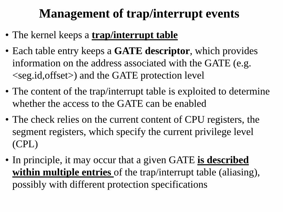
Management of trap/interrupt events
• The kernel keeps a trap/interrupt table
• Each table entry keeps a GATE descriptor, which provides
information on the address associated with the GATE (e.g.
<seg.id,offset>) and the GATE protection level
• The content of the trap/interrupt table is exploited to determine
whether the access to the GATE can be enabled
• The check relies on the current content of CPU registers, the
segment registers, which specify the current privilege level
(CPL)
• In principle, it may occur that a given GATE is described
within multiple entries of the trap/interrupt table (aliasing),
possibly with different protection specifications

Summary on x86 control flow variations
• intra-segment: standard jump instruction (e.g. JMP <displacement>
on x86 architectures)
firmware only verifies whether the displacement is within the
current segment boundary
• cross-segment: long jump instructions (e.g. LJMP <seg.id>,
<displacement> on x86 architectures)
Firmware verifies whether jump is enabled on the basis of
privilege levels (no CPL improvement is admitted)
Then, firmware checks whether the displacement is within the
segment boundaries
• cross-segment via GATEs: trap instructions (e.g. INT <table
displacement> on x86 architectures)
Firmware checks whether jumping is admitted depending on the
privilege level associated with the target GATE as specified
within the trap/interrupt table

An overview
Seg 0 – level = 0
Seg 1 – level 0
Seg i – level n
Not always admitted
(requires consulting the
Trap/interrupt table
+
Segment Tables)
Always admitted
(requires anyway consulting
the segment Tables)
Move across
segments

GATE details for the x86 architecture (i)
• The trap/interrupt table is called Interrupt Descriptor
Table (IDT)
• Any entry keeps
The ID of the target segment and the segment
displacement
the max level starting from which the access to the
GATE is granted
• IDT is accessible via the idtr register which is a packed
structure keeping the linear address of the IDT and the size
(number of entries, each made up by 8 or 16 bytes,
depending on whether extended 64-bit mode is active)
• The register is loadable via the LIDT machine instruction

GATE details for the x86 architecture (ii)
• We know the current privilege level is kept within CS
• If protection information enables jumping, the segment ID
within IDT is used to access GDT in order to check whether
jumping is within the segment boundaries
• If check succeeds the current privilege level gets updated
• The new value is taken from the corresponding entry of
GDT (this value corresponds to the privilege level of the
target segment)
• The GATE description also tells whether the activated code
is interruptible or not

Conventional operating systems
• For LINUX/Windows systems, the GATE for on-demand access
(via software traps) to the kernel is unique
• For i386 machines the corresponding software traps are
INT 0x80 for LINUX (with backward compatibility in x86-64)
INT 0x2E for Windows
• Any other GATE is reserved for the management of run-time errors
(e.g. divide by zero exceptions) and interrupts
• They are not usable for on-demand access via software (clearly
except if you hack the kernel)
• The software module associated with the on-demand access GATE
implements a dispatcher that is able to trigger the activation of
the specific system call targeted by the application

Data structures for system call dispatching
• There exists a “sytem call table” that keeps, in any entry, the
address of a specific system call
• Such an address becomes the target for a subroutine activation by
the dispatcher
• To access the correct entry, the dispatcher gets as input the
number (the numerical code) of the target system call
(typically this input is provided within a CPU register)
• The code is used to identify the target entry within the system call
table
• Then the dispatcher invokes the system call routine (as a “jump
sub-routine” – CALL instruction on x86)
• The actual system call, once executed, provides its output (return)
value within a CPU register

The trap-based dispatching scheme
User level
define input and
access GATE (trap)
dispatcher
Kernel level
System call table
System call
code
system call
activation
return from
trap
retrieve system call
return value
retrieve the reference to
the system call code

Trap vs interruptible execution
• Differently from interrupts, trap management is typically
configured so as not to entail/enable automatically resetting
the interruptible-state for the CPU-core
• Any critical code portion associated with the management of
the trap within the kernel requires explicit set of the
interruptible-state bit, and the reset after job is complete (e.g.
via CLI e STI instructions in x86 processors)
• For SMP/multi-core machines this may not suffice for
guaranteeing correctness (e.g. atomicity) while handling the
trap
• To address this issue, spinlock mechanisms are adopted, which
are base on atomic test-end-set code portions (e.g., generated
via the x86 LOCK prefix on standard compilation tool chains)

Test-and-set support
• Modern instruction sets offer a single instruction to
atomically test-and-set memory, this is the CAS (Compare
And Swap) intruction
• On x86 machines the actual CAS is called CMPXCHG
(Compare And Exchange)
• ... but we already discussed of this while dealing with
memory consistency!!

System call software components
• User side: software module (a) providing the input
parameters to the GATE (and to the actual system call) (b)
activating the GATE and (c) recovering the system call return
value
• kernel side:
dispatcher
system call table
actual system call code
• Addition of a new system call means working on both sides
• Typically, this happens with no intervention on the dispatcher
in all the cases where the system call format is compliant
with those predefined for the target operating system
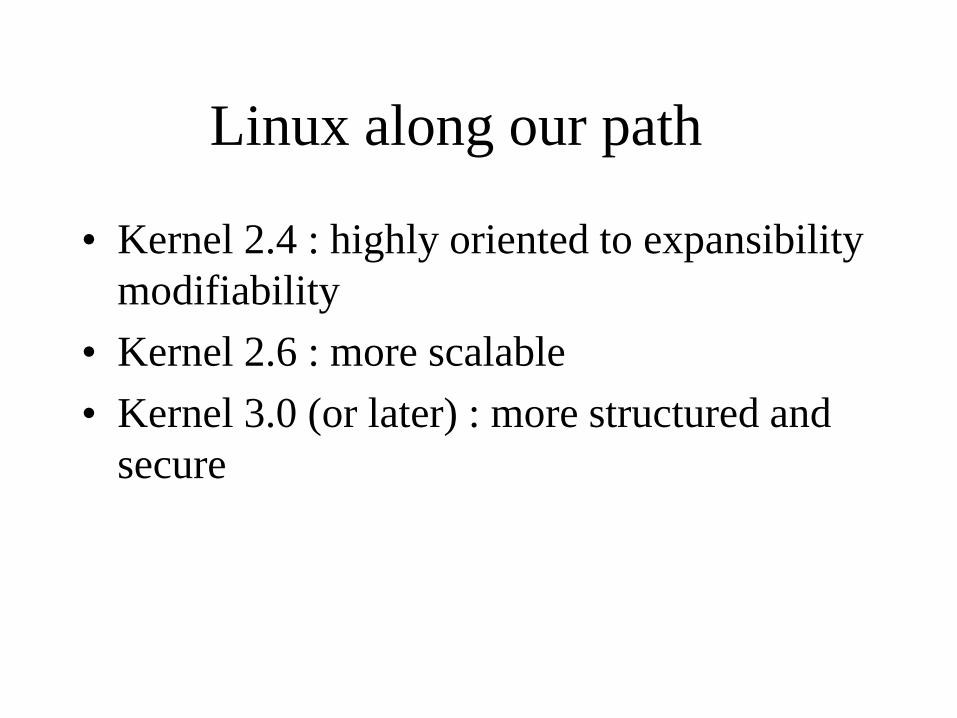
Linux along our path
• Kernel 2.4 : highly oriented to expansibility
modifiability
• Kernel 2.6 : more scalable
• Kernel 3.0 (or later) : more structured and
secure

LINUX system calls support:
path starting from kernel 2.4
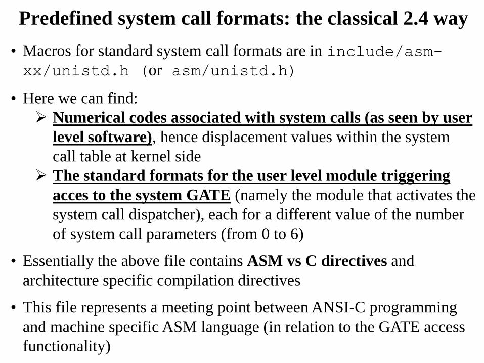
Predefined system call formats: the classical 2.4 way
• Macros for standard system call formats are in include/asm-
xx/unistd.h (or asm/unistd.h)
• Here we can find:
Numerical codes associated with system calls (as seen by user
level software), hence displacement values within the system
call table at kernel side
The standard formats for the user level module triggering
acces to the system GATE (namely the module that activates the
system call dispatcher), each for a different value of the number
of system call parameters (from 0 to 6)
• Essentially the above file contains ASM vs C directives and
architecture specific compilation directives
• This file represents a meeting point between ANSI-C programming
and machine specific ASM language (in relation to the GATE access
functionality)

System call numerical codes – 2.4.20 /*
* This file contains the system call numbers.
*/
#define __NR_exit 1
#define __NR_fork 2
#define __NR_read 3
#define __NR_write 4
#define __NR_open 5
#define __NR_close 6
#define __NR_waitpid 7
#define __NR_creat 8
#define __NR_link 9
#define __NR_unlink 10
#define __NR_execve 11
#define __NR_chdir 12
………
#define __NR_fallocate 324

User level tasks for accessing the gate GATE
1. Specification of the input parameters via CPU
registers (note that these include the actual system call
parameters and the dispatcher ones)
2. ASM instructions triggering the GATE (e.g. traps)
3. Recovery of the return value of the systems call (upon
returning from the trap associated with GATE
activation)

Code block for a standard system call with no
parameter (e.g. fork())
#define _syscall0(type,name) \
type name(void) \
{ \
long __res; \
__asm__ volatile ("int $0x80" \
: "=a" (__res) \
: "0" (__NR_##name)); \
__syscall_return(type,__res); \
}
Assembler instructions
Tasks preceding the assembler
code block
Tasks to be done after the
execution of the assembler
code block

Managing the return value and errno
/* user-visible error numbers are in the range -1 - -124:
see <asm-i386/errno.h> */
#define __syscall_return(type, res) \
do { \
if ((unsigned long)(res) >= (unsigned long)(-125)) { \
errno = -(res); \
res = -1; \
} \
return (type) (res); \
} while (0)
Case of res within the
interval [–1, -124]

Note: why the do/while(0) construct?
It is a C construct that allows to
• #define a multi-statement
operation
• put a semicolon after and
• still use within an if statement

Code block for a standard system call with
one parameter (e.g. close())
#define _syscall1(type,name,type1,arg1) \
type name(type1 arg1) \
{ \
long __res; \
__asm__ volatile ("int $0x80" \
: "=a" (__res) \
: "0" (__NR_##name),"b" ((long)(arg1))); \
__syscall_return(type,__res); \
}
2 registers used for the input

Code block for a system call with six parameters
(max admitted by the standard) – i386 bit case #define _syscall6(type,name,type1,arg1,type2,arg2,type3,arg3,type4,arg4,
\
type5,arg5,type6,arg6) \
type name (type1 arg1,type2 arg2,type3 arg3,type4 arg4,type5 arg5,type6
arg6) \
{ \
long __res; \
__asm__ volatile ("push %%ebp ; movl %%eax,%%ebp ; movl %1,%%eax ; int
$0x80 ; pop %%ebp" \
: "=a" (__res) \
: "i" (__NR_##name),"b" ((long)(arg1)),"c" ((long)(arg2)), \
"d" ((long)(arg3)),"S" ((long)(arg4)),"D" ((long)(arg5)), \
"0" ((long)(arg6))); \
__syscall_return(type,__res); \
}
We use 4 general purpose registers (eax,ebx,ecx,edx) plus the
additional registers ESI e EDI, and the ebp register (base pointer for
the current stack frame, which is saved before overwriting) and a
local integer variable “i”

i386 calling conventions for system calls
/*
* 0(%esp) - %ebx ARGS
* 4(%esp) - %ecx
* 8(%esp) - %edx
* C(%esp) - %esi
* 10(%esp) - %edi
* 14(%esp) - %ebp END ARGS
* 18(%esp) - %eax
* 1C(%esp) - %ds
* 20(%esp) - %es
* 24(%esp) - orig_eax
* 28(%esp) - %eip
* 2C(%esp) - %cs
* 30(%esp) - %eflags
* 34(%esp) - %oldesp
* 38(%esp) - %oldss
*/
Ring and baseline CPU
state information
(firmware saved onto
the system stack)
The stack layout representation
complies with the traditional
stack based passage of
parameters

x86-64 calling conventions for system calls
/*
* Register setup:
* rax system call number
* rdi arg0
* rcx return address for syscall/sysret, C arg3
* rsi arg1
* rdx arg2
* r10 arg3 (--> moved to rcx for C)
* r8 arg4
* r9 arg5
* r11 eflags for syscall/sysret, temporary for C
* r12-r15,rbp,rbx saved by C code, not touched.
*
* Interrupts are off on entry.
* Only called from user space.
*/

x86-64 system call re-indexing
• x86-64 Linux has re-indexed the system calls
available in the kernel
• A new table of defines describes the codes
associated with these system calls
• Such a table is available to user code programmers
via:
/local/include/linux/asm-x86/unistd_64.h
• However both the two different indexing mechanisms still
work …. we will se how they can co-exist in a while!!

Details on passing parameters
• Once gained control, the dispatcher will take a complete
snapshot of CPU registers
• The snapshot is taken within the system level stack
• Then the dispatcher will invoke the system call as a
subroutine call (e.g. via a CALL instruction in x86
architectures)
• The actual system call will retrieve the parameters according
to the ABI
• The taken snapshot can be modified by the dispatched upon
the system call return (e.g. for delivering the return value)

registers
System stack
upon triggering
dispatcher
Stack pointer
Base pointer
Stack pointer PC
Base pointer
Stack pointer PHASE 1 PHASE 2
PHASE 3
Dispatcher execution system call
execution
An example
Sys call NR
Sys call NR Sys call NR

Simple examples for adding system calls to
the user API
Provide a C file which: • includes unistd.h
• contains the definition of the numerical codes for the new system
calls
• contains the macro-definition for creating the actual standard
module associated with the new system calls (e.g. _syscall0())
#include <unistd.h>
#define _NR_my_first_sys_call 254
#define _NR_my_second_sys_call 255
_syscall0(int,my_first_sys_call);
_syscall1(int,my_second_sys_call,int,arg);
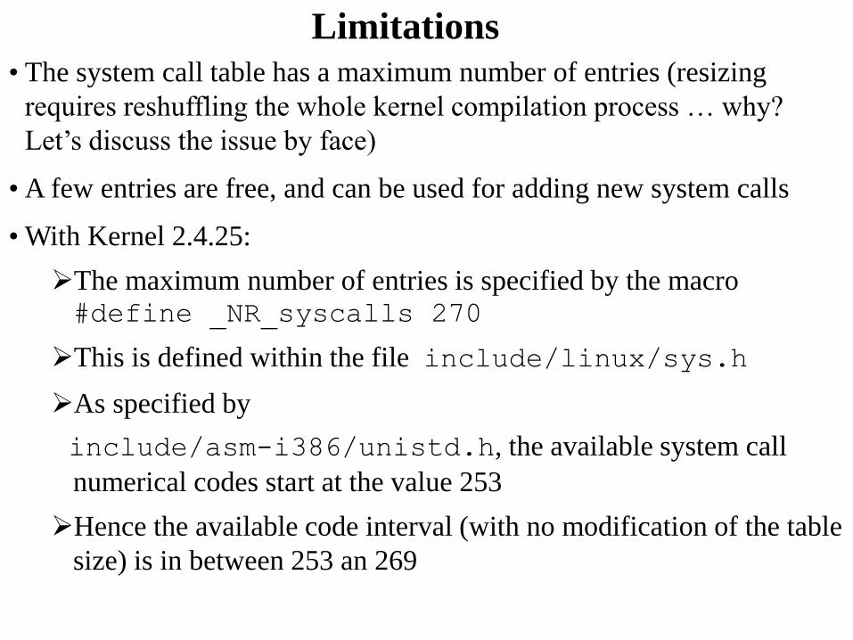
Limitations
• The system call table has a maximum number of entries (resizing
requires reshuffling the whole kernel compilation process … why?
Let’s discuss the issue by face)
• A few entries are free, and can be used for adding new system calls
• With Kernel 2.4.25:
The maximum number of entries is specified by the macro #define _NR_syscalls 270
This is defined within the file include/linux/sys.h
As specified by
include/asm-i386/unistd.h, the available system call
numerical codes start at the value 253
Hence the available code interval (with no modification of the table
size) is in between 253 an 269

An example for gcc version 3.3.3
(SuSE Linux)
#include <stdio.h>
#include <asm/unistd.h>
#include <errno.h>
#define __NR_pippo 256
_syscall0(void,pippo);
main() {
pippo();
}

Overriding the fork() i386 system call
#include <unistd.h>
#define __NR_my_fork 2 //same numerical code as the original
#define _new_syscall0(name) \
int name(void) \
{ \
asm("int $0x80" : : "a" (__NR_##my_fork) ); \
return 0; \
} \
_new_syscall0(my_fork)
int main(int a, char** b){
my_fork();
pause(); // there will be two processes pausing !!
}

“int 0x80” system call path performance implications
• One memory access to the IDT
• One memory access to the GDT to retrieve the
kernel CS segment
• One memory access to the GDT (namely the
TSS) to retrieve the kernel level stack pointer
• A lot of clock cycles waiting for data coming
from memory (just to control the execution flow)
• Asymmetric delays in asymmetric hardware (e.g.
NUMA)
• Unreliable outcome for time-interval measures
using system calls, see gettimeofday()

The x86 revolution (starting with Pentium3)
• CS value for kernel code cached into an apposite MSR
(Model Specific Register)
• Kernel entry point offset (the target EIP/RIP) kept into an
MSR
• Kernel level stack/data base kept into an MSR
• Entering kernel code is as easy as flushing the MSRs
values onto the corresponding original registers (e.g. CS,
DS, SS …. recall that the corresponding bases are
defaulted to 0x0)
• No memory access for activating the system call
dispatcher
• This is the fast system call path!!

Fast system call path additional details
SYSENTER instruction for 32 bits - SYSCALL instruction for 64 bits
based on (pseudo) register manipulation
• CS register set to the value of (SYSENTER_CS_MSR)
• EIP register set to the value of (SYSENTER_EIP_MSR)
• SS register set to the sum of (8 plus the value in
SYSENTER_CS_MSR)
• ESP register set to the value of (SYSENTER_ESP_MSR)
SYSEXIT instruction for 32 bits - SYSRET instruction for 64 bits
based on pseudo register manipulation
• CS register set to the sum of (16 plus the value in
SYSENTER_CS_MSR)
• EIP register set to the value contained in the EDX register
• SS register set to the sum of (24 plus the value in
SYSENTER_CS_MSR)
• ESP register set to the value contained in the ECX register

MSR and their setup
/usr/src/linux/include/asm/msr.h:
101 #define MSR_IA32_SYSENTER_CS 0x174
102 #define MSR_IA32_SYSENTER_ESP 0x175
103 #define MSR_IA32_SYSENTER_EIP 0x176
/usr/src/linux/arch/i386/kernel/sysenter.c:
36 wrmsr(MSR_IA32_SYSENTER_CS, __KERNEL_CS, 0);
37 wrmsr(MSR_IA32_SYSENTER_ESP, tss->esp1, 0);
38 wrmsr(MSR_IA32_SYSENTER_EIP,
(unsigned long) sysenter_entry, 0);
rdmsr and wrmsr are the actual machine instructions for
reading/writing the registers

The syscall() construct (Pentium3 – kernel 2.6)
• syscall() is implemented within glibc (in
stdlib.h)
• It allows triggering a trap to the kernel for the execution of
a generic system call
• The first argument is the system call number
• The other parameters are the input for the system call code
• The actual ASM code implementation of syscall() is
targeted and optimized for the specific architecture
• Specifically, the implementation (including the kernel level
counterpart) relies on ASM instructions such as
sysenter/sysexit or syscall/sysret, which
have been made available starting from Pentium3
processors

An example for gcc version 4.3.3 (Ubuntu
4.3.3-5ubuntu4) – backward-compatible
#include <stdlib.h>
#define __NR_my_first_sys_call 333
#define __NR_my_second_sys_call 334
int my_first_sys_call(){
return syscall(__NR_my_first_sys_call);
}
int my_second_sys_call(int arg1){
return syscall(__NR_my_second_sys_call, arg1);
}
int main(){
int x;
my_first_sys_call();
my_second_sys_call(x);
}

The system call table • The kernel level system call table is defined in specific files
• As an example, for kernel 2.4.20 and i386 machines it is
defined in arch/i386/kernel/entry.S
• As another example, for kernel 2.6.xx the table is posted on
the file arch/x86/kernel/syscall_table32.S
• As another example for kernel 4.15.xx and x86-64 the table
pointer is defined in /arch/x86/entry/syscall_64.c
• The .S files contains pre-processor ASM directives
• Any entry keeps a symbolic reference to the kernel level name
of a system call (typically, the kernel level name resembles the
one used at application level)
• The above files (or other .S) also contains the code block for
the dispatcher associated with the kernel access GATE

Table structure
ENTRY(sys_call_table)
.long SYMBOL_NAME(sys_ni_syscall) /* 0 - old "setup()"
system call*/
.long SYMBOL_NAME(sys_exit)
.long SYMBOL_NAME(sys_fork)
.long SYMBOL_NAME(sys_read)
.long SYMBOL_NAME(sys_write)
.long SYMBOL_NAME(sys_open) /* 5 */
.long SYMBOL_NAME(sys_close)
……
.long SYMBOL_NAME(sys_sendfile64)
.long SYMBOL_NAME(sys_ni_syscall) /* 240 reserved for futex
*/
………
.long SYMBOL_NAME(sys_ni_syscall) /* 252
sys_set_tid_address */
.rept NR_syscalls-(.-sys_call_table)/4
.long SYMBOL_NAME(sys_ni_syscall)
.endr
New symbols need to be inserted here

Definition of system call symbols
• For the previous example, the actual system call specification will
be
.long SYMBOL_NAME(sys_my_first_sys_call)
.long SYMBOL_NAME(sys_my_second_sys_call)
• The actual code for the system calls (generally based exclusively
on C with compilation directives for the specific architecture) can
be included within new modules added to the kernel or within
already exiting modules
• The actual code can rely on the kernel global data structures and
on functions already available within the kernel, except for the
case where they are explicitly masked (e.g. masking with
static declarations external to the file containing the system
call)

Compilation directives for kernel side
systems calls
• Specific directives are used to make the system call code compliant
with the dispatching rules
• Compliance is assessed on the basis of how the input
parameters are passed/retrieved
• The input parameters passage by convention historically took place
via the kernel stack
• The corresponding compilation directive is asmlinkage
• This directive is now mapped to the current ABI
• Hence for the previous examples we will have the following system
call definitions asmlinkage long sys_my_first_sys_call() { return 0;}
asmlinkage long sys_my_second_sys_call(int x) {
return ((x>0)?x:-x);}

The actual dispatcher (trap driven activation – i386
kernel 2.4)
ENTRY(system_call)
pushl %eax # save orig_eax
SAVE_ALL
GET_CURRENT(%ebx)
testb $0x02,tsk_ptrace(%ebx) # PT_TRACESYS
jne tracesys
cmpl $(NR_syscalls),%eax
jae badsys
call *SYMBOL_NAME(sys_call_table)(,%eax,4)
movl %eax,EAX(%esp) # save the return value
ENTRY(ret_from_sys_call)
cli # need_resched and signals atomic test
cmpl $0,need_resched(%ebx)
jne reschedule
cmpl $0,sigpending(%ebx)
jne signal_return
restore_all:
RESTORE_ALL
Manipulating
the CPU
snapshot in
the stack

The actual dispatcher (syscall driven activation –
kernel 2.4) ENTRY(system_call)
swapgs
movq %rsp,PDAREF(pda_oldrsp)
movq PDAREF(pda_kernelstack),%rsp
sti
SAVE_ARGS 8,1
movq %rax,ORIG_RAX-ARGOFFSET(%rsp)
movq %rcx,RIP-ARGOFFSET(%rsp)
GET_CURRENT(%rcx)
testl $PT_TRACESYS,tsk_ptrace(%rcx)
jne tracesys
cmpq $__NR_syscall_max,%rax
ja badsys
movq %r10,%rcx
call *sys_call_table(,%rax,8) # XXX: rip relative
movq %rax,RAX-ARGOFFSET(%rsp)
.globl ret_from_sys_call
ret_from_sys_call:
sysret_with_reschedule:
GET_CURRENT(%rcx)
cli
cmpq $0,tsk_need_resched(%rcx)
jne sysret_reschedule
cmpl $0,tsk_sigpending(%rcx)
jne sysret_signal
sysret_restore_args:
……….
#define PDAREF(field) %gs:field
Part of the stack switch
work originally one
via firmware is moved
to software

User vs kernel GS segment

Virtual Dynamic Shared Object (VDSO)
• Kernel also setups system call entry/exit points for user processes
• Kernel creates a single page (or a few) in memory and attaches it
to all processes' address space when they are loaded into
memory.
• This page contains the actual implementation of the system call
entry/exit mechanism
• For i386 the definition of this page can be found in the file /usr/src/linux/arch/i386/kernel/vsyscall-
sysenter.S
• Kernel calls this page virtual dynamic shared object (VDSO)
• Originally exploited for making the fast system call path
available (in relation to a few services)

VDSO and the address space
text
data bss
heap
stack
VDSO
User accessible memory
Environmental
software is allowed
to know where
VDSO is located
Kernel posts
code here

SYNOPSIS
#include <sys/auxv.h>
void *vdso = (uintptr_t) getauxval(AT_SYSINFO_EHDR);
DESCRIPTION
The "vDSO" (virtual dynamic shared object) is a small
shared library that the kernel automatically maps into the
address space of all user-space applications. Applications
usually do not need to concern themselves with these
details as the vDSO is most commonly called by the C
library. This way you can code in the normal way using
standard functions and the C library will take care of using
any functionality that is available via the vDSO.
Application exposed facilities

The actual VDSO
The kernel level target is ENTRY(sysenter_entry)

Performance effects
• The VDSO exploits flat (linear) addressing proper of
operating system memory managers in order to bypass
segmentation and the related operations
• It therefore reduces the number of accessed to memory in
order to support the change to kernel mode
• Studies show that the reduction of clock cycles for system
calls can be of the order of 75%
• This is in the end typical for any usage of the fast system call
path

The current picture
• VDSO is now used to replace the old facilities supported via
the vsyscall section, say support for specific system calls (e.g. query system calls such as gettimeofday())
• VDSO is randomized (in terms of positioning into the
address space) so security gets increased
• The system call mechanism in the wide, which relies on sysenter/syscall and sysexit/sysret, is in
charge of the dynamic linker (ld-linux.so)

Back to the coexistence of slow and
fast system call paths
• Slow path
Still based on int 0x80
Still accessing IDT/GDT (which is the reason why the
target entry still requires to be populated)
The kernel level system call dispatched accesses the i386
system call table
• Fast path
Base on the syscall instruction (no IDT/GDT access)
The kernel level dispatcher (different from the previous
one) accesses the x86-64 system call table

Kernel software organization
• About the 90% of the actual code for system calls is
embedded within a few main portions of the kernel archive
• These are contained in the following directories
kernel (process and used management)
mm (basic memory management)
ipc (interprocess communication management)
fs (virtual file system management)
net (network management)

Kernel compiling
• You can exploit make
• It executed a set of tasks (compilation, assembly and linking tasks)
which are specified via a Makefile
• This file can specify differentiated actions to be done (possibly
exhibiting dependencies) which are described within a field called
target
• Each action can be specified by the following syntax:
action-name: [ dependency-name]*{new-line}
{tab} action-body
• Further, we can define variables via the syntax:
variable-name = value
• Any variable can be accessed via the syntax:
$(variable-name)

Standard compilation steps (old style)
1. make config
this triggers a configuration script which is used for
tailoring compilation to the specific machine and user
needs
2. make dep
which determines the software modules dependencies
3. make bzImage
which creates a bootable image of the kernel and logs it
as
arch/i386/boot/bzImage

make config (or menuconfig)
make
make modules
make modules_install (ROOT)
make install (ROOT)
mkinitrd (or mkinitramfs) –o initrd.img-<vers> <vers>
update-grub
OR
grub-mkconfig -o /boot/grub/grub.cfg (ROOT)
Standard compilation steps (current tyle)

About ‘config’
• The possibilities
– allyesconfig (likelihood of conflicting modules)
– allnoconfig (likelohood of non-sufficient services in
the kernel image)
– Answer to the individual questions you may be
asked for
– Retrieve a good configuration file (depending on
you machine/settings) on the web
– Reuse the configuration files(s) you find in the
/boot directory of your root file system (likely
works when recompiling the same kernel version
you already have)

Role of initrd
• It is a RAM disk
• It can be (temporary) mounted as the root file
system and programs can be run from it
• A different root file system can be then mounted
from a different device
• The previous root (from initrd) can then be moved
to a directory and can be subsequently unmounted
• With initrd system startup can occur in two phases
– the kernel initially comes up with a minimum
set of compiled-in drivers
– additional modules are loaded from initrd

make config (or menuconfig)
make
make modules
make modules_install (ROOT) (writes into
/lib/modules)
make install (ROOT) (writes into /boot: the kernel
image, the system map and the config file)
update-grub
OR
grub-mkconfig -o /boot/grub/grub.cfg (ROOT)
Step effects

“Extended” Kernel compilation (up to 2.4)
• Makefile updates
1. setting of the EXTRAVERSION variable (non-mandatory)
2. update of the CORE_FILES variable such in a way to
include the directory that contains the added C files and to
specify the object file name tageted by the compilation
3. update the SUBDIRS variable so to include the new directory
• Put a specific Makefile within the directory that contains the
source code to be compiled, which should be structured as
O_TARGET := object-file-name.o
export-objs := list of obj to be exported
obj-y := C files list (marked with .o)
include $(TOPDIR)/Rules.make

“Extended” Kernel compilation (from 2.4)
• Makefile updates
1. setting of the EXTRAVERSION variable
(non-mandatory)
2. use obj- directive to add a file or a
directory into the compilation tree
3. the addition is within already available
makefiles (or new ones)

Kernel anatomy: the systems map
• It contains the symbols and the corresponding virtual
memory reference (as determined at compile/link time)
for:
• Kernel functions (steady state ones)
• Kernel data structures
• Each symbol is also associated with a tag that defines the
‘storage class’ as determined by the compiling process
• As an example, 'T' usually denotes a global (non-static
but not necessarily exported) function, 't' a function local
to the compilation unit (i.e. static), 'D' global data, 'd'
data local to the compilation unit. 'R' and 'r' same as
'D'/'d' but for read-only data

System map applications
• Kernel debugging
• Kernel run-time hacking
• The system map is also (partially) reported by the (pseudo) file /proc/kallsysm
• The latter is exploited for run-time kernel
‘hacking’ via the modules’ technology

Just an example
2.6.5-7.282-smp #1 SMP ……. i686 i686 i386 GNU/Linux
c03a8a00 D sys_call_table
2.6.32-5-amd64 #1 SMP ……… x86_64 GNU/Linux
ffffffff81308240 R sys_call_table
Read/write data
Read-only data