ms & bts layer specification
TRANSCRIPT
7/27/2019 MS & BTS Layer Specification
http://slidepdf.com/reader/full/ms-bts-layer-specification 1/59
ETSI EN 300 938 V8.0.1 (2000-09)
European Standard (Telecommunications series)
Digital cellular telecommunications system (Phase 2+);Mobile Station - Base Station System (MS - BSS) interface;
Data Link (DL) layer specification(GSM 04.06 version 8.0.1 Release 1999)
GLOBAL SYSTEM FOR
MOBILE COMMUNICATIONS
R
7/27/2019 MS & BTS Layer Specification
http://slidepdf.com/reader/full/ms-bts-layer-specification 2/59ETSI
ETSI EN 300 938 V8.0.1 (2000-09)2(GSM 04.06 version 8.0.1 Release 1999)
ReferenceREN/SMG-020406Q8
Keywords
Digital cellular telecommunications system,Global System for Mobile communications (GSM)
ETSI
650 Route des LuciolesF-06921 Sophia Antipolis Cedex - FRANCE
Tel.: +33 4 92 94 42 00 Fax: +33 4 93 65 47 16
Siret N°348 623 562 00017 - NAF 742 CAssociation à but non lucratif enregistrée à laSous-Préfecture de Grasse (06) N°7803/88
Important notice
Individual copies of the present document can be downloaded from:http://www.etsi.org
The present document may be made available in more than one electronic version or in print. In any case of existing orperceived difference in contents between such versions, the reference version is the Portable Document Format (PDF).
In case of dispute, the reference shall be the printing on ETSI printers of the PDF version kept on a specific network drivewithin ETSI Secretariat.
Users of the present document should be aware that the document may be subject to revision or change of status.Information on the current status of this and other ETSI documents is available at http://www.etsi.org/tb/status/
If you find errors in the present document, send your comment to:[email protected]
Copyright Notification
No part may be reproduced except as authorized by written permission.The copyright and the foregoing restriction extend to reproduction in all media.
© European Telecommunications Standards Institute 2000.All rights reserved.
7/27/2019 MS & BTS Layer Specification
http://slidepdf.com/reader/full/ms-bts-layer-specification 3/59ETSI
ETSI EN 300 938 V8.0.1 (2000-09)3(GSM 04.06 version 8.0.1 Release 1999)
Contents
Intellectual Property Rights................................................................................................................................7
Foreword.............................................................................................................................................................7
0 Scope ........................................................................................................................................................80.1 References..........................................................................................................................................................80.2 Abbreviations .....................................................................................................................................................8
1 General .....................................................................................................................................................91.1 Options ...............................................................................................................................................................9
2 Frame structure for peer-to-peer communication...................................................................................102.1 General .............................................................................................................................................................10
2.2 Frame delimitation and fill bits ........................................................................................................................12
2.3 Address field ....................................................................................................................................................122.4 Control field .....................................................................................................................................................13
2.5 Length indicator field .......................................................................................................................................132.5a Short L2 header type 1 .....................................................................................................................................13
2.6 Information field ..............................................................................................................................................13
2.7 Transparency ....................................................................................................................................................13
2.8 Format convention............................................................................................................................................132.8.1 Numbering convention ...............................................................................................................................13
2.8.2 Order of bit transmission ............................................................................................................................13
2.8.3 Field mapping convention ..........................................................................................................................13
3 Elements of procedures and formats of fields for Data Link Layer peer-to-peer communication.........143.1 General .............................................................................................................................................................14
3.2 Address field format.........................................................................................................................................14
3.3 Address field variables .....................................................................................................................................15
3.3.1 Address field extension bit (EA).................................................................................................................153.3.2 Command/response field bit (C/R) .............................................................................................................153.3.3 Service access point identifier (SAPI) ........................................................................................................15
3.4 Control field formats ........................................................................................................................................15
3.4.1 Information transfer format - I ....................................................................................................................15
3.4.2 Supervisory format - S................................................................................................................................16
3.4.3 Unnumbered format - U..............................................................................................................................16
3.4a Short L2 header type 1 .....................................................................................................................................16
3.5 Control field parameters and associated state variables ...................................................................................16
3.5.1 Poll/Final bit ...............................................................................................................................................16
3.5.2 Multiple frame operation - variables and sequence numbers......................................................................17
3.5.2.1 Modulus ................................................................................................................................................17
3.5.2.2 Send state variable V(S)........................................................................................................................17
3.5.2.3 Acknowledge state variable V(A).........................................................................................................173.5.2.4 Send sequence number N(S) .................................................................................................................17
3.5.2.5 Receive state variable V(R)...................................................................................................................17
3.5.2.6 Receive sequence number N(R)............................................................................................................17
3.5.2.7 Other parameters and variables.............................................................................................................18
3.5.3 Unacknowledged operation variables and parameters................................................................................18
3.6 Length indicator field format............................................................................................................................18
3.7 Length indicator field variables........................................................................................................................18
3.7.1 Length indicator field extension bit (EL)....................................................................................................18
3.7.2 More data bit (M)........................................................................................................................................18
3.7.3 Length indicator (L)....................................................................................................................................18
3.8 Commands and responses ................................................................................................................................19
3.8.1 Information (I) commands ..........................................................................................................................19
3.8.2 Set asynchronous balanced mode (SABM) command................................................................................193.8.3 Disconnect (DISC) command .....................................................................................................................20
3.8.4 Unnumbered information (UI) command ...................................................................................................20
3.8.5 Receive ready (RR) command/response.....................................................................................................20
7/27/2019 MS & BTS Layer Specification
http://slidepdf.com/reader/full/ms-bts-layer-specification 4/59ETSI
ETSI EN 300 938 V8.0.1 (2000-09)4(GSM 04.06 version 8.0.1 Release 1999)
3.8.6 Reject (REJ) command/response ................................................................................................................21
3.8.7 Receive not ready (RNR) command/response............................................................................................21
3.8.8 Unnumbered acknowledgement (UA) response .........................................................................................21
3.8.9 Disconnected mode (DM) response............................................................................................................21
4 Elements for layer-to-layer communication...........................................................................................224.1 Definition of primitives and parameters...........................................................................................................22
4.1.1 Generic names ............................................................................................................................................22
4.1.1.1 DL-ESTABLISH ..................................................................................................................................22
4.1.1.2 DL-RELEASE ......................................................................................................................................224.1.1.3 DL-DATA.............................................................................................................................................22
4.1.1.4 DL-UNIT DATA ..................................................................................................................................22
4.1.1.5 DL-SUSPEND ......................................................................................................................................22
4.1.1.6 DL-RESUME........................................................................................................................................22
4.1.1.7 DL-RECONNECT................................................................................................................................23
4.1.1.8 DL-RANDOM ACCESS ......................................................................................................................234.1.1.9 MDL-RELEASE...................................................................................................................................23
4.1.1.10 MDL-ERROR .......................................................................................................................................23
4.1.1.11 PH-DATA .............................................................................................................................................23
4.1.1.12 PH-RANDOM ACCESS ......................................................................................................................23
4.1.1.13 PH-CONNECT .....................................................................................................................................23
4.1.1.14 PH-READY-TO-SEND ........................................................................................................................234.1.1.15 PH-EMPTY-FRAME............................................................................................................................23
4.1.2 Primitives types ..........................................................................................................................................23
4.1.2.1 REQUEST.............................................................................................................................................24
4.1.2.2 INDICATION .......................................................................................................................................24
4.1.2.3 RESPONSE...........................................................................................................................................24
4.1.2.4 CONFIRM ............................................................................................................................................24
4.1.3 Parameter definition....................................................................................................................................25
4.1.3.1 Message unit .........................................................................................................................................25
4.1.3.2 Channel type .........................................................................................................................................25
4.1.3.3 Service Access Point.............................................................................................................................25
4.1.3.4 Release mode ........................................................................................................................................25
4.1.3.5 Error cause ............................................................................................................................................25
4.1.3.6 Establish mode ......................................................................................................................................26
4.1.3.7 L2 header type.......................................................................................................................................26
4.1.3.8 Priority ..................................................................................................................................................26
4.2 Primitive procedures.........................................................................................................................................30
5 Definition of the peer-to-peer protocol LAPDm....................................................................................305.1 General .............................................................................................................................................................30
5.2 General Protocol Procedures............................................................................................................................31
5.2.1 Unacknowledged information transfer........................................................................................................315.2.2 Acknowledged multiple frame information transfer...................................................................................32
5.3 Procedures for unacknowledged information transfer......................................................................................32
5.3.1 General........................................................................................................................................................32
5.3.2 Transmission of unacknowledged information...........................................................................................325.3.3 Receipt of unacknowledged information ....................................................................................................32
5.4 Procedures for establishment and release of multiple frame operation ............................................................325.4.1 Establishment of multiple frame operation.................................................................................................32
5.4.1.1 General..................................................................................................................................................32
5.4.1.2 Normal establishment procedures .........................................................................................................33
5.4.1.3 Procedure on expiry of timer T200: Normal establishment ..................................................................34
5.4.1.4 Contention resolution establishment procedure ....................................................................................345.4.1.5 Procedure on expiry of timer T200: contention resolution (MS only) ..................................................36
5.4.2 Information transfer ....................................................................................................................................36
5.4.2.1 General requirements ............................................................................................................................36
5.4.2.2 Error conditions.....................................................................................................................................36
5.4.2.3 Fill frames .............................................................................................................................................37
5.4.3 Suspension and resumption of multiple frame operation............................................................................385.4.3.1 General..................................................................................................................................................38
5.4.3.2 Suspension ............................................................................................................................................38
7/27/2019 MS & BTS Layer Specification
http://slidepdf.com/reader/full/ms-bts-layer-specification 5/59ETSI
ETSI EN 300 938 V8.0.1 (2000-09)5(GSM 04.06 version 8.0.1 Release 1999)
5.4.3.3 Resumption ...........................................................................................................................................39
5.4.3.3.1 Procedure after channel change .......................................................................................................39
5.4.3.3.2 Procedure after returning to the old channel (MS only) ..................................................................39
5.4.4 Termination of multiple frame operation....................................................................................................40
5.4.4.1 General..................................................................................................................................................40
5.4.4.2 Normal release procedure .....................................................................................................................40
5.4.4.3 Procedure on expiry of timer T200 for normal release .........................................................................405.4.4.4 Local end release procedure..................................................................................................................41
5.4.5 Idle state......................................................................................................................................................41
5.4.6 Collision of unnumbered commands and responses ...................................................................................41
5.4.6.1 Identical transmitted and received commands ......................................................................................415.4.6.2 Different transmitted and received commands......................................................................................42
5.4.6.3 Unsolicited DM response and SABM or DISC command ....................................................................42
5.5 Procedures for information transfer in multiple frame operation .....................................................................42
5.5.1 Transmitting I frames..................................................................................................................................42
5.5.2 Receiving I frames ......................................................................................................................................43
5.5.2.1 P bit of the received I frame set to "1" ..................................................................................................435.5.2.2 P bit of the received I frame set to "0" ..................................................................................................43
5.5.3 Receiving acknowledgement ......................................................................................................................44
5.5.3.1 On receipt of a valid I frame .................................................................................................................445.5.3.2 Receiving supervisory command frames with the P bit set to "1" ........................................................44
5.5.4 Receiving REJ frames.................................................................................................................................44
5.5.4.1 Receipt of a valid REJ frame.................................................................................................................445.5.4.2 Transmitting frames ..............................................................................................................................45
5.5.5 Receiving RNR frame.................................................................................................................................45
5.5.6 Data link layer own receiver busy condition...............................................................................................46
5.5.7 Waiting acknowledgement .........................................................................................................................47
5.5.8 Preemption..................................................................................................................................................47
5.5.8.1 Sender Requirements ............................................................................................................................485.5.8.2 Receiver Requirements .........................................................................................................................48
5.6 Abnormal release and re-establishment of multiple frame operation...............................................................48
5.6.1 Criteria for re-establishment .......................................................................................................................48
5.6.2 Criteria for abnormal release ......................................................................................................................485.6.3 Procedures for re-establishment..................................................................................................................49
5.6.4 Procedures for abnormal release .................................................................................................................49
5.7 Exception condition reporting and recovery for multiple frame operation ......................................................49
5.7.1 N(S) sequence error ....................................................................................................................................49
5.7.2 Timer recovery............................................................................................................................................50
5.7.3 Invalid frame condition...............................................................................................................................50
5.7.4 N(R) sequence error....................................................................................................................................50
5.8 List of system parameters.................................................................................................................................50
5.8.1 Timer T200 .................................................................................................................................................51
5.8.1.1 For SAPI=0 and SAPI=3.......................................................................................................................51
5.8.1.2 For SAPIs other than 0 or 3...................................................................................................................51
5.8.2 Maximum number of retransmissions (N200)............................................................................................51
5.8.2.1 For SAPI=0 and 3 .................................................................................................................................515.8.2.2 For SAPIs other than 0 or 3...................................................................................................................51
5.8.3 Maximum number of octets in an I, UI, SABM and UA frame partially or entirely available forthe information field (N201) ....................................................... ......................................................... ......51
5.8.4 Maximum number of outstanding I frames (k) ...........................................................................................525.8.5 Maximum number of octets in a Layer 3 message .....................................................................................52
5.9 System performance requirements ...................................................................................................................52
6 Special protocol operation on SAPI=0 and SAPI=3 ..............................................................................53
Annex A (normative): Random access procedures ...........................................................................54
A.1 Description of the procedure ..................................................................................................................54A.1.1 Procedure in the MS .........................................................................................................................................54
A.1.2 Procedure in the BS..........................................................................................................................................54
7/27/2019 MS & BTS Layer Specification
http://slidepdf.com/reader/full/ms-bts-layer-specification 6/59ETSI
ETSI EN 300 938 V8.0.1 (2000-09)6(GSM 04.06 version 8.0.1 Release 1999)
A.2 Format ....................................................................................................................................................54
Annex G (normative): Handling of frames with parameter errors in the address, control
and length indicator fields.............................................................................55
G.1 General ...................................................................................................................................................55
G.2 Parameter errors in the address field ......................................................................................................55G.2.1 Unallocated SAPI .............................................................................................................................................55
G.2.2 Wrong value of the C/R bit ..............................................................................................................................55
G.2.3 EA bit set to "0"................................................................................................................................................55
G.3 Parameter errors in the control field.......................................................................................................56G.3.1 Supervisory frames...........................................................................................................................................56
G.3.2 Unnumbered frames .........................................................................................................................................56
G.4 Parameter errors in the length indicator field .........................................................................................56G.4.1 EL bit error.......................................................................................................................................................56
G.4.2 Information frames ...........................................................................................................................................56
G.4.3 Supervisory frames...........................................................................................................................................57
G.4.4 DISC and DM frames.......................................................................................................................................57
G.4.5 SABM UA and UI frames................................................................................................................................57
Annex H (informative): Change Request History................................................................................58
History ..............................................................................................................................................................59
7/27/2019 MS & BTS Layer Specification
http://slidepdf.com/reader/full/ms-bts-layer-specification 7/59ETSI
ETSI EN 300 938 V8.0.1 (2000-09)7(GSM 04.06 version 8.0.1 Release 1999)
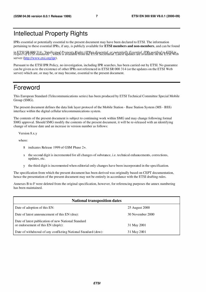
Intellectual Property Rights
IPRs essential or potentially essential to the present document may have been declared to ETSI. The information
pertaining to these essential IPRs, if any, is publicly available for ETSI members and non-members, and can be found
in ETSI SR 000 314: "Intellectual Property Rights (IPRs); Essential, or potentially Essential, IPRs notified to ETSI inrespect of ETSI standards" , which is available from the ETSI Secretariat. Latest updates are available on the ETSI Web
server (http://www.etsi.org/ipr).
Pursuant to the ETSI IPR Policy, no investigation, including IPR searches, has been carried out by ETSI. No guaranteecan be given as to the existence of other IPRs not referenced in ETSI SR 000 314 (or the updates on the ETSI Web
server) which are, or may be, or may become, essential to the present document.
Foreword
This European Standard (Telecommunications series) has been produced by ETSI Technical Committee Special Mobile
Group (SMG).
The present document defines the data link layer protocol of the Mobile Station - Base Station System (MS - BSS)interface within the digital cellular telecommunications system.
The contents of the present document is subject to continuing work within SMG and may change following formal
SMG approval. Should SMG modify the contents of the present document, it will be re-released with an identifying
change of release date and an increase in version number as follows:
Version 8.x.y
where:
8 indicates Release 1999 of GSM Phase 2+.
x the second digit is incremented for all changes of substance, i.e. technical enhancements, corrections,updates, etc.
y the third digit is incremented when editorial only changes have been incorporated in the specification.
The specification from which the present document has been derived was originally based on CEPT documentation,
hence the presentation of the present document may not be entirely in accordance with the ETSI drafting rules.
Annexes B to F were deleted from the original specification, however, for referencing purposes the annex numbering
has been maintained.
National transposition dates
Date of adoption of this EN: 25 August 2000
Date of latest announcement of this EN (doa): 30 November 2000
Date of latest publication of new National Standard
or endorsement of this EN (dop/e): 31 May 2001
Date of withdrawal of any conflicting National Standard (dow): 31 May 2001
7/27/2019 MS & BTS Layer Specification
http://slidepdf.com/reader/full/ms-bts-layer-specification 8/59ETSI
ETSI EN 300 938 V8.0.1 (2000-09)8(GSM 04.06 version 8.0.1 Release 1999)
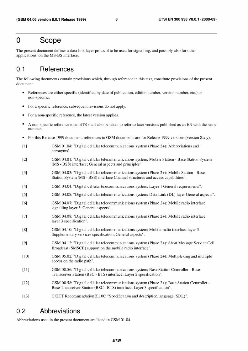
0 Scope
The present document defines a data link layer protocol to be used for signalling, and possibly also for other
applications, on the MS-BS interface.
0.1 References
The following documents contain provisions which, through reference in this text, constitute provisions of the present
document.
• References are either specific (identified by date of publication, edition number, version number, etc.) or
non-specific.
• For a specific reference, subsequent revisions do not apply.
• For a non-specific reference, the latest version applies.
• A non-specific reference to an ETS shall also be taken to refer to later versions published as an EN with the samenumber.
• For this Release 1999 document, references to GSM documents are for Release 1999 versions (version 8.x.y).
[1] GSM 01.04: "Digital cellular telecommunications system (Phase 2+); Abbreviations and
acronyms".
[2] GSM 04.01: "Digital cellular telecommunications system; Mobile Station - Base Station System
(MS - BSS) interface; General aspects and principles".
[3] GSM 04.03: "Digital cellular telecommunications system (Phase 2+); Mobile Station - Base
Station System (MS - BSS) interface Channel structures and access capabilities".
[4] GSM 04.04: "Digital cellular telecommunications system; Layer 1 General requirements".
[5] GSM 04.05: "Digital cellular telecommunications system; Data Link (DL) layer General aspects".
[6] GSM 04.07: "Digital cellular telecommunications system (Phase 2+); Mobile radio interface
signalling layer 3; General aspects".
[7] GSM 04.08: "Digital cellular telecommunications system (Phase 2+); Mobile radio interface
layer 3 specification".
[8] GSM 04.10: "Digital cellular telecommunications system; Mobile radio interface layer 3
Supplementary services specification; General aspects".
[9] GSM 04.12: "Digital cellular telecommunications system (Phase 2+); Short Message Service Cell
Broadcast (SMSCB) support on the mobile radio interface".
[10] GSM 05.02: "Digital cellular telecommunications system (Phase 2+); Multiplexing and multiple
access on the radio path".
[11] GSM 08.56: "Digital cellular telecommunications system; Base Station Controller - Base
Transceiver Station (BSC - BTS) interface; Layer 2 specification".
[12] GSM 08.58: "Digital cellular telecommunications system (Phase 2+); Base Station Controller -
Base Transceiver Station (BSC - BTS) interface; Layer 3 specification".
[13] CCITT Recommendation Z.100: "Specification and description language (SDL)".
0.2 AbbreviationsAbbreviations used in the present document are listed in GSM 01.04.
7/27/2019 MS & BTS Layer Specification
http://slidepdf.com/reader/full/ms-bts-layer-specification 9/59ETSI
ETSI EN 300 938 V8.0.1 (2000-09)9(GSM 04.06 version 8.0.1 Release 1999)
1 General
The present document describes the frame structure, elements of procedure, format of fields and procedures for the
proper operation of the Link Access Procedure on the Dm channel, LAPDm.
NOTE 1: The term Dm channel is used for convenience to designate the collection of all the various signalling
channels required in the GSM system. See also GSM 04.03.
The concepts, terminology, overview description of LAPDm functions and procedures, and the relationship with other
Technical Specifications are described in general terms in GSM 04.05.
The frame formats defined for LAPDm are based on those defined for LAPD. However, there are important differences
between LAPDm and LAPD, in particular with regard to frame delimitation methods and transparency mechanisms.
These differences are necessary for operation within the constraints set by the radio path.
LAPDm supports two modes of operation:
- unacknowledged operation using UI frames;
- acknowledged operation using the multiple frame procedure.
As a choice of implementation, the two modes of operation may be implemented independently of each other. This is
possible since there is no interactions between the two modes, other than queuing at the transmitter, even when they
coexist on the same physical channel. For BCCHs and CCCHs only the unacknowledged mode of operation needs to be
implemented.
LAPDm is used for information sent on the control channels BCCH, AGCH, NCH, PCH, FACCH, SACCH andSDCCH as defined in GSM 04.03.
NOTE 2: AGCH, NCH and PCH are sometimes referred to by the collective name CCCH and FACCH, SACCH
and SDCCH are, similarly, referred to by the collective name DCCH.
LAPDm may also be used on other types of channel.
NOTE 3: As stated in GSM 04.05, the term "data link layer" is used in the main text of this Technical Specification.
However, mainly in figures and tables, the terms "layer 2" and "L2" are used as abbreviations.
Furthermore, in accordance with GSM 04.07 and GSM 04.08, the term "layer 3" is used to indicate the
layer above the data link layer.
This Technical Specification is organized as follows:
The frame structure for peer-to-peer communication is given in clause 2. The elements of procedure and formats of
fields are given in clause 3. The elements of layer-to-layer communication are contained in clause 4. The details of the
peer-to-peer procedures are given in clause 5. Section 6 summarizes the special protocol operations used mandatorilywith SAPI=0 and SAP = 3.
The specification for the random access channel is contained in annex A, even though it is not a LAPDm function. The
present document is descriptive and does not constrain the implementation of the random access function. Theprocedure is used for CHANNEL REQUEST on the RACH and HANDOVER ACCESS on the main DCCH.
(Annexes B to F are deleted).
Annex G gives an overview of actions taken on frames containing parameter errors.
1.1 Options
Support of short L2 header type 1 is an option in both the mobile station and the network; under certain conditions the
support is mandatory, as specified in other Specifications. A layer 2 protocol entity not implementing short L2 header
type 1 shall diagnose an E/A bit error and proceed as defined in annex G.2.3.

7/27/2019 MS & BTS Layer Specification
http://slidepdf.com/reader/full/ms-bts-layer-specification 10/59ETSI
ETSI EN 300 938 V8.0.1 (2000-09)10(GSM 04.06 version 8.0.1 Release 1999)
2 Frame structure for peer-to-peer communication
2.1 General
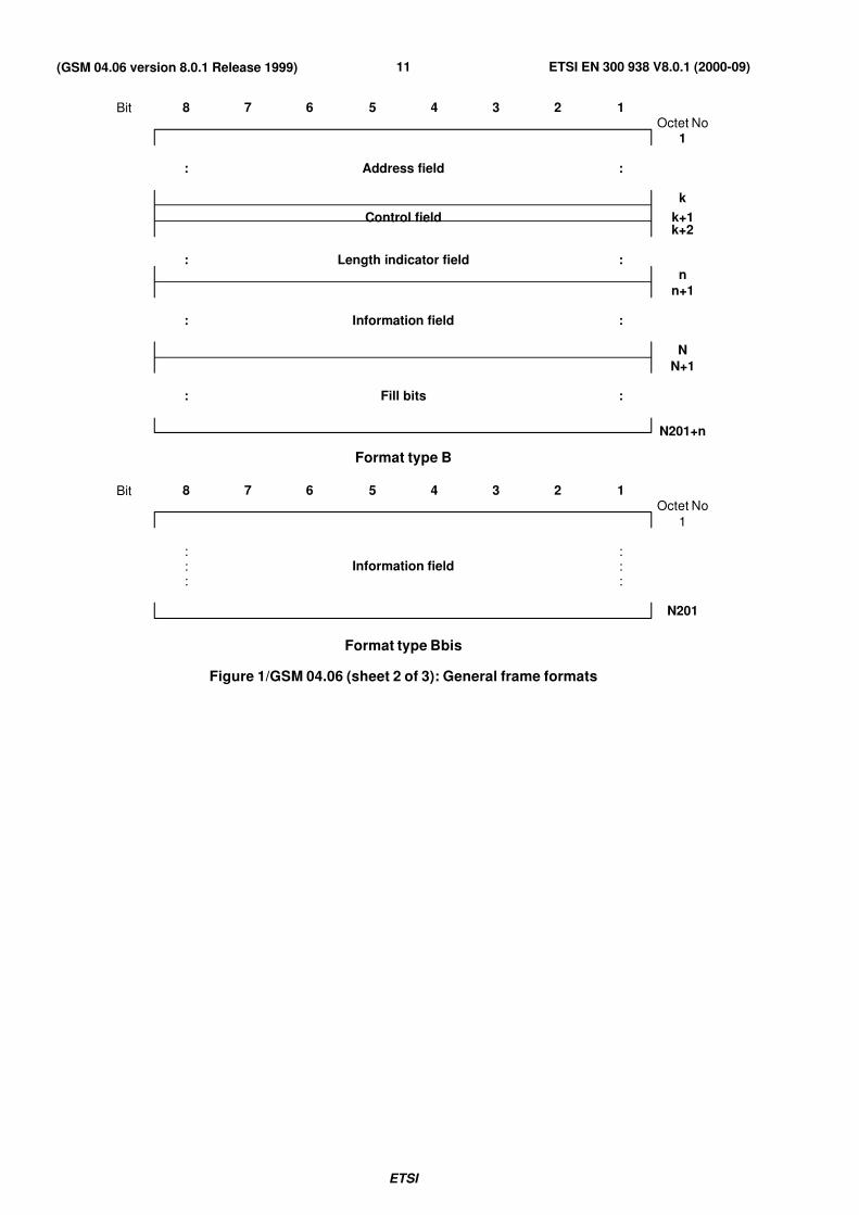
All data link layer peer-to-peer exchanges are in frames conforming to one of the formats shown in figure 1. Severalformat types are shown in the figure:
- Format A is used on DCCHs for frames where there is no information field.
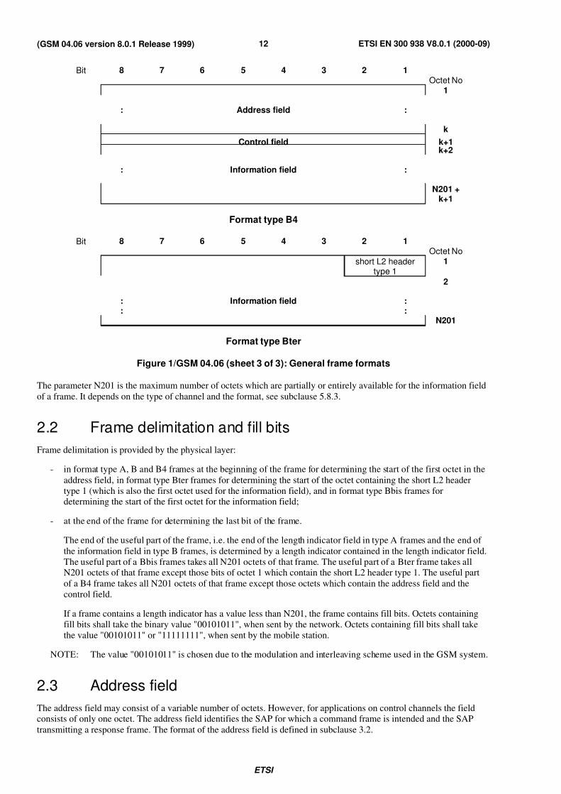
- Formats B, Bter and B4 are used on DCCHs for frames containing an information field:
- format Bter is used on request of higher layers if and only if short L2 header type 1 is supported and a UI
command is to be transmitted on SAPI 0;
- format B4 is used for UI frames transmitted by the network on SACCH;
- format B is applied in all other cases.
- Format Bbis is used only on BCCH, PCH, NCH, and AGCH.
- In addition there is a Format C for transmission of random access signals.
Format C frames are described in annex A. Format A, B, Bbis, Bter and B4 frames are described in the remainder of the
present document.
Bit 8 7 6 5 4 3 2 1Octet No
1
: Address field :
k
Control field k+1
k+2
: Length indicator field :
n
n+1
: Fill bits :
N201+n
Format type A
Figure 1/GSM 04.06 (sheet 1 of 3): General frame formats
7/27/2019 MS & BTS Layer Specification
http://slidepdf.com/reader/full/ms-bts-layer-specification 11/59ETSI
ETSI EN 300 938 V8.0.1 (2000-09)11(GSM 04.06 version 8.0.1 Release 1999)
Bit 8 7 6 5 4 3 2 1Octet No
1
: Address field :
k
Control field k+1k+2
: Length indicator field :n
n+1
: Information field :
N
N+1
: Fill bits :
N201+n
Format type B
Bit 8 7 6 5 4 3 2 1Octet No
1
: :: Information field :: :
N201
Format type Bbis
Figure 1/GSM 04.06 (sheet 2 of 3): General frame formats
7/27/2019 MS & BTS Layer Specification
http://slidepdf.com/reader/full/ms-bts-layer-specification 12/59ETSI
ETSI EN 300 938 V8.0.1 (2000-09)12(GSM 04.06 version 8.0.1 Release 1999)
Bit 8 7 6 5 4 3 2 1Octet No
1
: Address field :
k
Control field k+1k+2
: Information field :
N201 +k+1
Format type B4
Bit 8 7 6 5 4 3 2 1Octet No
short L2 headertype 1
1
2
: Information field :: :
N201
Format type Bter
Figure 1/GSM 04.06 (sheet 3 of 3): General frame formats
The parameter N201 is the maximum number of octets which are partially or entirely available for the information field
of a frame. It depends on the type of channel and the format, see subclause 5.8.3.
2.2 Frame delimitation and fill bits
Frame delimitation is provided by the physical layer:
- in format type A, B and B4 frames at the beginning of the frame for determining the start of the first octet in the
address field, in format type Bter frames for determining the start of the octet containing the short L2 header
type 1 (which is also the first octet used for the information field), and in format type Bbis frames fordetermining the start of the first octet for the information field;
- at the end of the frame for determining the last bit of the frame.
The end of the useful part of the frame, i.e. the end of the length indicator field in type A frames and the end of
the information field in type B frames, is determined by a length indicator contained in the length indicator field.
The useful part of a Bbis frames takes all N201 octets of that frame. The useful part of a Bter frame takes allN201 octets of that frame except those bits of octet 1 which contain the short L2 header type 1. The useful part
of a B4 frame takes all N201 octets of that frame except those octets which contain the address field and the
control field.
If a frame contains a length indicator has a value less than N201, the frame contains fill bits. Octets containing
fill bits shall take the binary value "00101011", when sent by the network. Octets containing fill bits shall take
the value "00101011" or "11111111", when sent by the mobile station.
NOTE: The value "00101011" is chosen due to the modulation and interleaving scheme used in the GSM system.
2.3 Address field
The address field may consist of a variable number of octets. However, for applications on control channels the fieldconsists of only one octet. The address field identifies the SAP for which a command frame is intended and the SAP
transmitting a response frame. The format of the address field is defined in subclause 3.2.
7/27/2019 MS & BTS Layer Specification
http://slidepdf.com/reader/full/ms-bts-layer-specification 13/59ETSI
ETSI EN 300 938 V8.0.1 (2000-09)13(GSM 04.06 version 8.0.1 Release 1999)
2.4 Control field
The control field consists of one octet. The format of the control field is defined in subclause 3.4.
2.5 Length indicator field
The length indicator field may consist of a variable number of octets. However, for applications on control channels the
field consists of only one octet. The format of the field is defined in subclause 3.6.
2.5a Short L2 header type 1
The short L2 header type 1 consists of two bits. Its contents are defined in subclause 3.4a.
2.6 Information field
The information field of a frame, when present, has the position in the frame defined in 2.1.
The maximum number of octets in the information field (N201) is defined in subclause 5.8.3.
2.7 Transparency
Because of the frame delimitation technique used (see subclause 2.2), the frame can include any possible sequence of
bits without the need for additional transparency mechanisms.
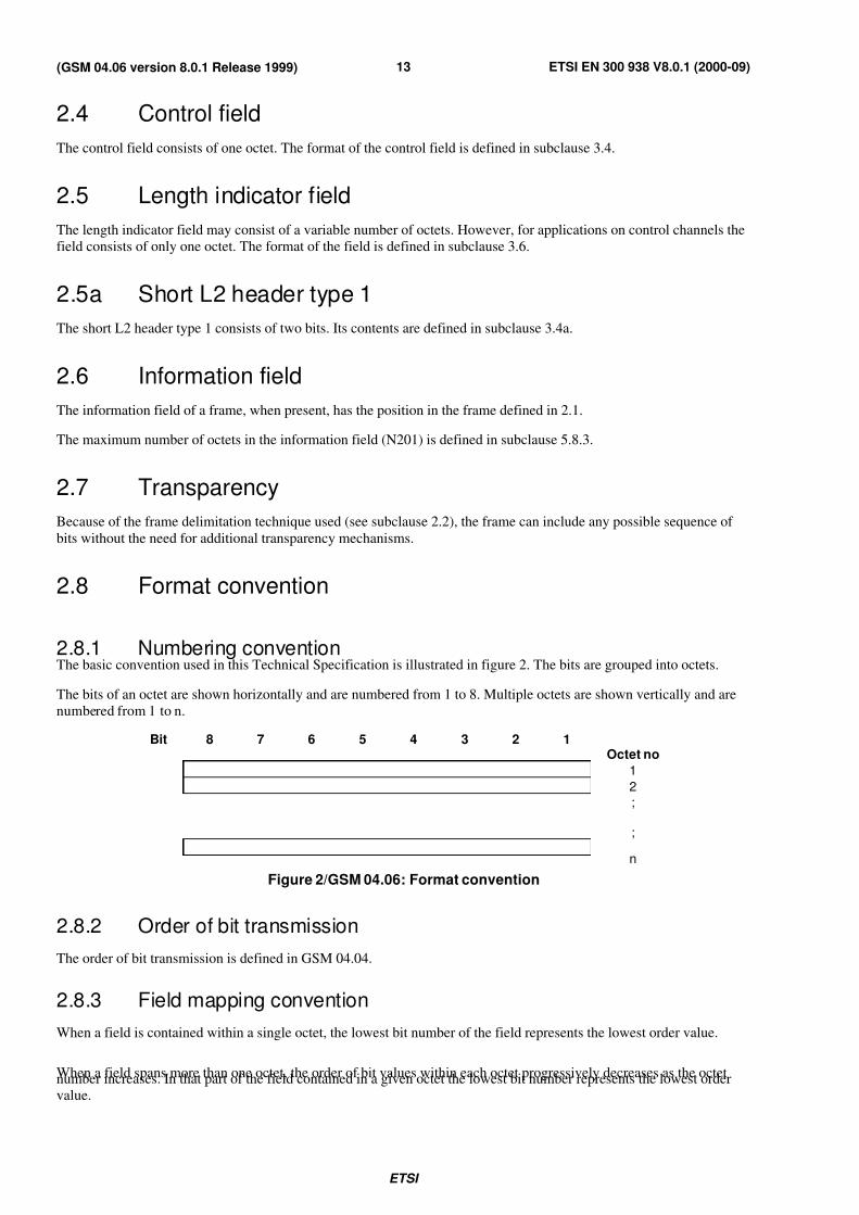
2.8 Format convention
2.8.1 Numbering conventionThe basic convention used in this Technical Specification is illustrated in figure 2. The bits are grouped into octets.
The bits of an octet are shown horizontally and are numbered from 1 to 8. Multiple octets are shown vertically and are
numbered from 1 to n.
Bit 8 7 6 5 4 3 2 1Octet no
1
2
;
;
n
Figure 2/GSM 04.06: Format convention
2.8.2 Order of bit transmission
The order of bit transmission is defined in GSM 04.04.
2.8.3 Field mapping convention
When a field is contained within a single octet, the lowest bit number of the field represents the lowest order value.
When a field spans more than one octet, the order of bit values within each octet progressively decreases as the octetnumber increases. In that part of the field contained in a given octet the lowest bit number represents the lowest order
value.
7/27/2019 MS & BTS Layer Specification
http://slidepdf.com/reader/full/ms-bts-layer-specification 14/59ETSI
ETSI EN 300 938 V8.0.1 (2000-09)14(GSM 04.06 version 8.0.1 Release 1999)
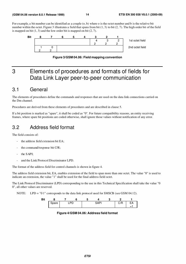
For example, a bit number can be identified as a couple (o, b) where o is the octet number and b is the relative bit
number within the octet. Figure 3 illustrates a field that spans from bit (1, 3) to bit (2, 7). The high order bit of the field
is mapped on bit (1, 3) and the low order bit is mapped on bit (2, 7).
Bit 8 7 6 5 4 3 2 1
4 3 2 1st octet field2 2 2
1 0 2nd octet field2 2
Figure 3/GSM 04.06: Field mapping convention
3 Elements of procedures and formats of fields forData Link Layer peer-to-peer communication
3.1 General
The elements of procedures define the commands and responses that are used on the data link connections carried on
the Dm channel.
Procedures are derived from these elements of procedures and are described in clause 5.
If a bit position is marked as "spare", it shall be coded as "0". For future compatibility reasons, an entity receiving
frames, where spare bit positions are coded otherwise, shall ignore those values without notification of any error.
3.2 Address field format
The field consists of:
- the address field extension bit EA;
- the command/response bit C/R;
- the SAPI;
- and the Link Protocol Discriminator LPD.
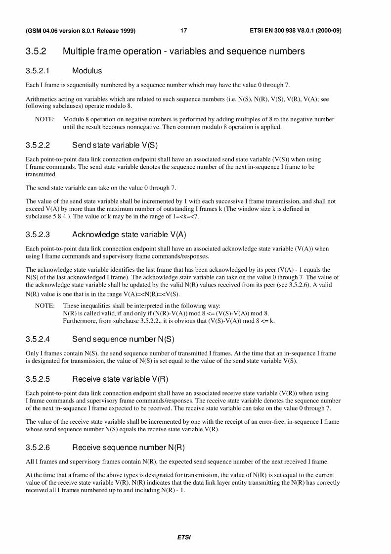
The format of the address field for control channels is shown in figure 4.
The address field extension bit, EA, enables extension of the field to span more than one octet. The value "0" is used to
indicate an extension, the value "1" shall be used for the final address field octet.
The Link Protocol Discriminator (LPD) corresponding to the use in this Technical Specification shall take the value "0
0", all other values are reserved.
NOTE: LPD = "0 1" corresponds to the data link protocol used for SMSCB (see GSM 04.12).
Bit 8 7 6 5 4 3 2 1
Spare LPD SAPI C/R EA=1
Figure 4/GSM 04.06: Address field format
7/27/2019 MS & BTS Layer Specification
http://slidepdf.com/reader/full/ms-bts-layer-specification 15/59ETSI
ETSI EN 300 938 V8.0.1 (2000-09)15(GSM 04.06 version 8.0.1 Release 1999)
3.3 Address field variables
3.3.1 Address field extension bit (EA)
The address field range is extended by reserving the first transmitted bit of the address field octets to indicate the final
octet of the address field. The presence of a "1" in the first bit of an address field octet signals that it is the final octet of the address field. Figure 4 shows the case where the field consists of one octet.
3.3.2 Command/response field bit (C/R)
The C/R bit identifies a frame as either a command or a response. The MS side shall send commands with the C/R bit
set to "0", and responses with the C/R bit set to "1". The BS side shall do the opposite; that is commands are sent with
C/R set to "1", and responses are sent with C/R set to "0". The combinations for the BS side and MS side are shown in
table 1.
Table 1/GSM 04.06: C/R field bit usage
Type Direction C/R value
Command BS side to MS side 1MS side to BS side 0
Response BS side to MS side 0
MS side to BS side 1
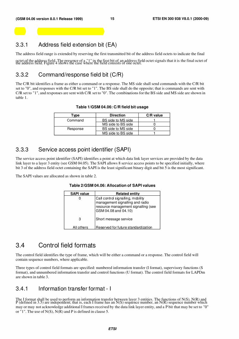
3.3.3 Service access point identifier (SAPI)
The service access point identifier (SAPI) identifies a point at which data link layer services are provided by the data
link layer to a layer 3 entity (see GSM 04.05). The SAPI allows 8 service access points to be specified initially, where
bit 3 of the address field octet containing the SAPI is the least significant binary digit and bit 5 is the most significant.
The SAPI values are allocated as shown in table 2.
Table 2/GSM 04.06: Allocation of SAPI values
SAPI value Related entity
0 Call control signalling, mobilitymanagement signalling and radioresource management signalling (seeGSM 04.08 and 04.10)
3 Short message service
All others Reserved for future standardization
3.4 Control field formats
The control field identifies the type of frame, which will be either a command or a response. The control field willcontain sequence numbers, where applicable.
Three types of control field formats are specified: numbered information transfer (I format), supervisory functions (S
format), and unnumbered information transfer and control functions (U format). The control field formats for LAPDm
are shown in table 3.
3.4.1 Information transfer format - I
The I format shall be used to perform an information transfer between layer 3 entities. The functions of N(S), N(R) andP (defined in 3.5) are independent; that is, each I frame has an N(S) sequence number, an N(R) sequence number whichmay or may not acknowledge additional I frames received by the data link layer entity, and a P bit that may be set to "0"
or "1". The use of N(S), N(R) and P is defined in clause 5.
7/27/2019 MS & BTS Layer Specification
http://slidepdf.com/reader/full/ms-bts-layer-specification 16/59ETSI
ETSI EN 300 938 V8.0.1 (2000-09)16(GSM 04.06 version 8.0.1 Release 1999)
3.4.2 Supervisory format - S
The S format shall be used to perform data link supervisory control functions such as: acknowledge I frames, requestretransmission of I frames, and request a temporary suspension of transmission of I frames. The functions of N(R) and
P/F are independent; that is, each supervisory frame has an N(R) sequence number which may or may not acknowledge
additional I frames received by the data link layer entity, and a P/F bit that may be set to "0" or "1".
The use of N(R) and the P/F bit is described in clause 5.
3.4.3 Unnumbered format - U
The U format shall be used to provide additional data link control functions and unacknowledged information transfer.
This format does not contain sequence numbers. It does include a P/F bit that may be set to "0" or "1".
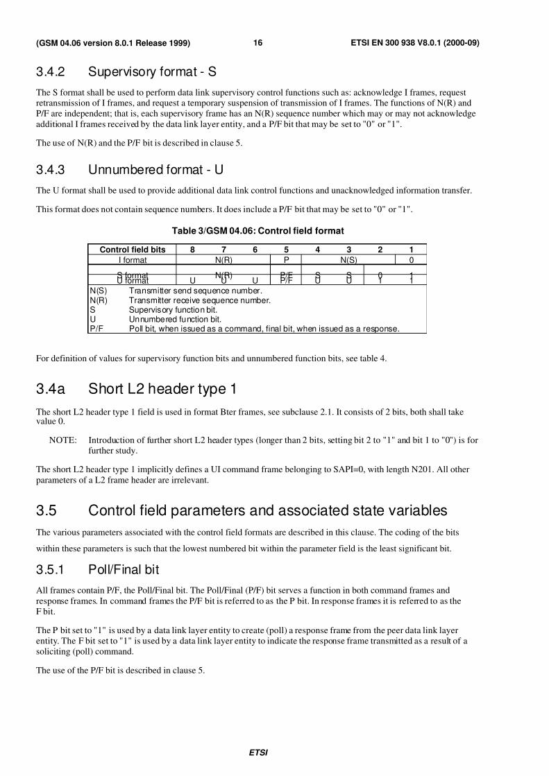
Table 3/GSM 04.06: Control field format
Control field bits 8 7 6 5 4 3 2 1
I format N(R) P N(S) 0
S format N(R) P/F S S 0 1U format U U U P/F U U 1 1
N(S) Transmitter send sequence number.N(R) Transmitter receive sequence number.S Supervisory function bit.U Unnumbered function bit.P/F Poll bit, when issued as a command, final bit, when issued as a response.
For definition of values for supervisory function bits and unnumbered function bits, see table 4.
3.4a Short L2 header type 1
The short L2 header type 1 field is used in format Bter frames, see subclause 2.1. It consists of 2 bits, both shall takevalue 0.
NOTE: Introduction of further short L2 header types (longer than 2 bits, setting bit 2 to "1" and bit 1 to "0") is forfurther study.
The short L2 header type 1 implicitly defines a UI command frame belonging to SAPI=0, with length N201. All other
parameters of a L2 frame header are irrelevant.
3.5 Control field parameters and associated state variables
The various parameters associated with the control field formats are described in this clause. The coding of the bits
within these parameters is such that the lowest numbered bit within the parameter field is the least significant bit.
3.5.1 Poll/Final bit
All frames contain P/F, the Poll/Final bit. The Poll/Final (P/F) bit serves a function in both command frames and
response frames. In command frames the P/F bit is referred to as the P bit. In response frames it is referred to as the
F bit.
The P bit set to "1" is used by a data link layer entity to create (poll) a response frame from the peer data link layer
entity. The F bit set to "1" is used by a data link layer entity to indicate the response frame transmitted as a result of a
soliciting (poll) command.
The use of the P/F bit is described in clause 5.
7/27/2019 MS & BTS Layer Specification
http://slidepdf.com/reader/full/ms-bts-layer-specification 17/59ETSI
ETSI EN 300 938 V8.0.1 (2000-09)17(GSM 04.06 version 8.0.1 Release 1999)
3.5.2 Multiple frame operation - variables and sequence numbers
3.5.2.1 Modulus
Each I frame is sequentially numbered by a sequence number which may have the value 0 through 7.
Arithmetics acting on variables which are related to such sequence numbers (i.e. N(S), N(R), V(S), V(R), V(A); seefollowing subclauses) operate modulo 8.
NOTE: Modulo 8 operation on negative numbers is performed by adding multiples of 8 to the negative number
until the result becomes nonnegative. Then common modulo 8 operation is applied.
3.5.2.2 Send state variable V(S)
Each point-to-point data link connection endpoint shall have an associated send state variable (V(S)) when using
I frame commands. The send state variable denotes the sequence number of the next in-sequence I frame to betransmitted.
The send state variable can take on the value 0 through 7.
The value of the send state variable shall be incremented by 1 with each successive I frame transmission, and shall not
exceed V(A) by more than the maximum number of outstanding I frames k (The window size k is defined in
subclause 5.8.4.). The value of k may be in the range of 1=<k=<7.
3.5.2.3 Acknowledge state variable V(A)
Each point-to-point data link connection endpoint shall have an associated acknowledge state variable (V(A)) when
using I frame commands and supervisory frame commands/responses.
The acknowledge state variable identifies the last frame that has been acknowledged by its peer (V(A) - 1 equals the
N(S) of the last acknowledged I frame). The acknowledge state variable can take on the value 0 through 7. The value of
the acknowledge state variable shall be updated by the valid N(R) values received from its peer (see 3.5.2.6). A valid
N(R) value is one that is in the range V(A)=<N(R)=<V(S).
NOTE: These inequalities shall be interpreted in the following way:
N(R) is called valid, if and only if (N(R)-V(A)) mod 8 <= (V(S)-V(A)) mod 8.
Furthermore, from subclause 3.5.2.2., it is obvious that (V(S)-V(A)) mod 8 <= k.
3.5.2.4 Send sequence number N(S)
Only I frames contain N(S), the send sequence number of transmitted I frames. At the time that an in-sequence I frame
is designated for transmission, the value of N(S) is set equal to the value of the send state variable V(S).
3.5.2.5 Receive state variable V(R)
Each point-to-point data link connection endpoint shall have an associated receive state variable (V(R)) when usingI frame commands and supervisory frame commands/responses. The receive state variable denotes the sequence number
of the next in-sequence I frame expected to be received. The receive state variable can take on the value 0 through 7.
The value of the receive state variable shall be incremented by one with the receipt of an error-free, in-sequence I frame
whose send sequence number N(S) equals the receive state variable V(R).
3.5.2.6 Receive sequence number N(R)
All I frames and supervisory frames contain N(R), the expected send sequence number of the next received I frame.
At the time that a frame of the above types is designated for transmission, the value of N(R) is set equal to the current
value of the receive state variable V(R). N(R) indicates that the data link layer entity transmitting the N(R) has correctly
received all I frames numbered up to and including N(R) - 1.
7/27/2019 MS & BTS Layer Specification
http://slidepdf.com/reader/full/ms-bts-layer-specification 18/59ETSI
ETSI EN 300 938 V8.0.1 (2000-09)18(GSM 04.06 version 8.0.1 Release 1999)
3.5.2.7 Other parameters and variables
For definition and values of parameters and variables such as timer T200, maximum number of retransmissions (N200),
window size (k) and the maximum number of octets in an information field (N201), see subclause 5.8.
3.5.3 Unacknowledged operation variables and parameters
The only parameter defined for unacknowledged operation is the number of octets (N201) in the information field of the
UI frame. See subclause 5.8.3.
3.6 Length indicator field format
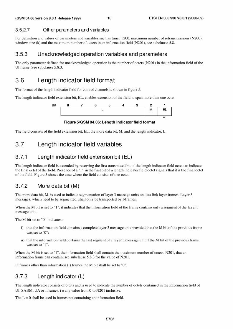
The format of the length indicator field for control channels is shown in figure 5.
The length indicator field extension bit, EL, enables extension of the field to span more than one octet.
Bit 8 7 6 5 4 3 2 1
L M EL
=1
Figure 5/GSM 04.06: Length indicator field format
The field consists of the field extension bit, EL, the more data bit, M, and the length indicator, L.
3.7 Length indicator field variables
3.7.1 Length indicator field extension bit (EL)
The length indicator field is extended by reserving the first transmitted bit of the length indicator field octets to indicate
the final octet of the field. Presence of a "1" in the first bit of a length indicator field octet signals that it is the final octet
of the field. Figure 5 shows the case where the field consists of one octet.
3.7.2 More data bit (M)
The more data bit, M, is used to indicate segmentation of layer 3 message units on data link layer frames. Layer 3
messages, which need to be segmented, shall only be transported by I-frames.
When the M bit is set to "1", it indicates that the information field of the frame contains only a segment of the layer 3
message unit.
The M bit set to "0" indicates:
i) that the information field contains a complete layer 3 message unit provided that the M bit of the previous frame
was set to "0";
ii) that the information field contains the last segment of a layer 3 message unit if the M bit of the previous frame
was set to "1".
When the M bit is set to "1", the information field shall contain the maximum number of octets, N201, that an
information frame can contain, see subclause 5.8.3 for the value of N201.
In frames other than information (I) frames the M bit shall be set to "0".
3.7.3 Length indicator (L)
The length indicator consists of 6 bits and is used to indicate the number of octets contained in the information field of
UI, SABM, UA or I frames, i e any value from 0 to N201 inclusive.
The L = 0 shall be used in frames not containing an information field.
7/27/2019 MS & BTS Layer Specification
http://slidepdf.com/reader/full/ms-bts-layer-specification 19/59ETSI
ETSI EN 300 938 V8.0.1 (2000-09)19(GSM 04.06 version 8.0.1 Release 1999)
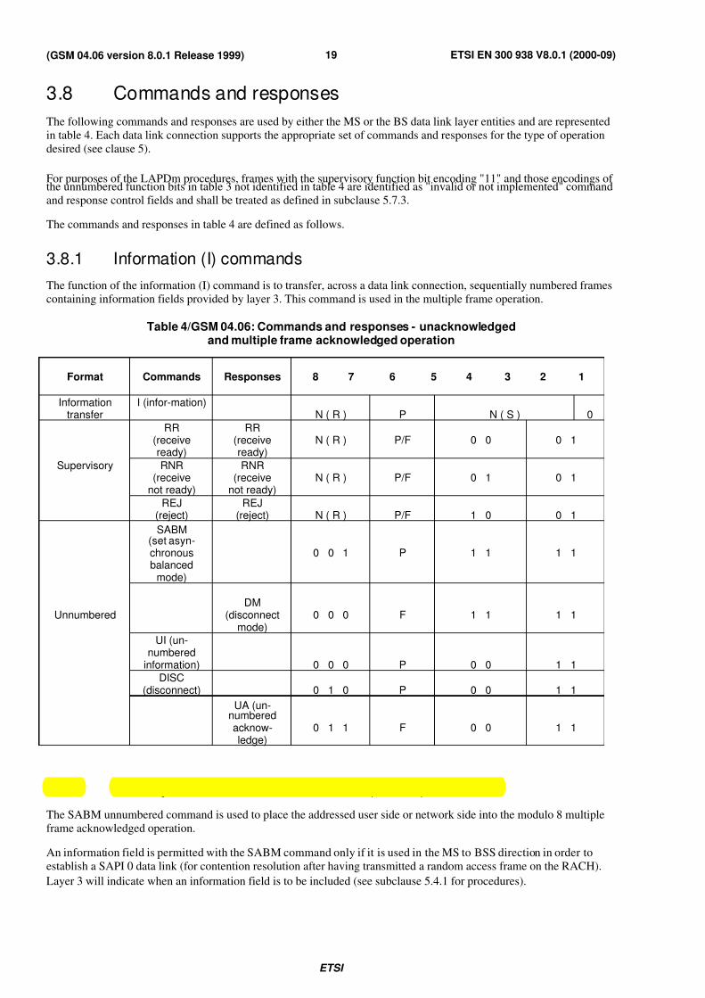
3.8 Commands and responses
The following commands and responses are used by either the MS or the BS data link layer entities and are represented
in table 4. Each data link connection supports the appropriate set of commands and responses for the type of operation
desired (see clause 5).
For purposes of the LAPDm procedures, frames with the supervisory function bit encoding "11" and those encodings of the unnumbered function bits in table 3 not identified in table 4 are identified as "invalid or not implemented" command
and response control fields and shall be treated as defined in subclause 5.7.3.
The commands and responses in table 4 are defined as follows.
3.8.1 Information (I) commands
The function of the information (I) command is to transfer, across a data link connection, sequentially numbered frames
containing information fields provided by layer 3. This command is used in the multiple frame operation.
Table 4/GSM 04.06: Commands and responses - unacknowledgedand multiple frame acknowledged operation
Format Commands Responses 8 7 6 5 4 3 2 1
Informationtransfer
I (infor-mation)N ( R ) P N ( S ) 0
RR(receiveready)
RR(receiveready)
N ( R ) P/F 0 0 0 1
Supervisory RNR(receive
not ready)
RNR(receive
not ready)N ( R ) P/F 0 1 0 1
REJ(reject)
REJ(reject) N ( R ) P/F 1 0 0 1
SABM(set asyn-chronousbalanced
mode)
0 0 1 P 1 1 1 1
UnnumberedDM
(disconnectmode)
0 0 0 F 1 1 1 1
UI (un-numbered
information) 0 0 0 P 0 0 1 1
DISC(disconnect) 0 1 0 P 0 0 1 1
UA (un-numbered
acknow-ledge)
0 1 1 F 0 0 1 1
3.8.2 Set asynchronous balanced mode (SABM) command
The SABM unnumbered command is used to place the addressed user side or network side into the modulo 8 multiple
frame acknowledged operation.
An information field is permitted with the SABM command only if it is used in the MS to BSS direction in order to
establish a SAPI 0 data link (for contention resolution after having transmitted a random access frame on the RACH).
Layer 3 will indicate when an information field is to be included (see subclause 5.4.1 for procedures).

7/27/2019 MS & BTS Layer Specification
http://slidepdf.com/reader/full/ms-bts-layer-specification 20/59

7/27/2019 MS & BTS Layer Specification
http://slidepdf.com/reader/full/ms-bts-layer-specification 21/59
7/27/2019 MS & BTS Layer Specification
http://slidepdf.com/reader/full/ms-bts-layer-specification 22/59ETSI
ETSI EN 300 938 V8.0.1 (2000-09)22(GSM 04.06 version 8.0.1 Release 1999)
4 Elements for layer-to-layer communication
4.1 Definition of primitives and parameters
Communications between layers and between the data link layer and layer 3 are accomplished by means of primitives.
Primitives represent, in an abstract way, the logical exchange of information and control between the data link layer andadjacent layers. They do not specify or constrain implementations.
Primitives consist of commands and their respective responses associated with the services requested of a lower layer.
The general syntax of a primitive is:
XX - Generic name - Type (Parameters);
where XX designates the layer providing the service. For the present document XX is DL for the data link layer, PH for
the physical layer and MDL for administrative functions (e.g. error reporting and recovery).
4.1.1 Generic namesThe generic name specifies the activity that the identified layer should perform. Table 5 illustrates the primitives
defined in the present document.
The primitive generic names that are defined in the present document are:
4.1.1.1 DL-ESTABLISH
The DL-ESTABLISH primitives are used to request, confirm and indicate the outcome of the procedures for
establishing multiple frame operation.
4.1.1.2 DL-RELEASE
The DL-RELEASE primitives are used to request, confirm and indicate the outcome of the procedures for terminating a
previously established multiple frame operation.
In the case of a data link layer malfunction, layer 3 will be notified by a RELEASE indication.
4.1.1.3 DL-DATA
The DL-DATA primitives are used to pass to and from the data link layer layer 3 message units which are to be
transmitted, or have been received, using multiple frame acknowledged operation.
4.1.1.4 DL-UNIT DATA
The DL-UNIT DATA primitives are used to pass to and from the data link layer, layer 3 message units which are to be
transmitted, or have been received, using unacknowledged operation.
4.1.1.5 DL-SUSPEND
The DL-SUSPEND primitive is used in the mobile station by the radio resource management entity to perform a local
end release in such a way, that the layer 3 data units and the state of the transmit and receive counters are saved.
4.1.1.6 DL-RESUME
The DL-RESUME primitive is used in the mobile station by the radio resource management entity to establish multiple
frame operation and resume communication with the network without loss of layer 3 messages. The layer 3 data unit
passed to layer 2 together with that primitive is sent with priority (e.g. ASSIGNMENT COMPLETE or HANDOVERCOMPLETE).
7/27/2019 MS & BTS Layer Specification
http://slidepdf.com/reader/full/ms-bts-layer-specification 23/59ETSI
ETSI EN 300 938 V8.0.1 (2000-09)23(GSM 04.06 version 8.0.1 Release 1999)
4.1.1.7 DL-RECONNECT
The DL-RECONNECT primitive is used in the mobile station by the radio resource management entity to restore
multiple frame operation on the old channel after failure of the channel change. The layer 3 data unit passed to layer 2
with previous DL-RESUME-REQUEST (i.e. ASSIGNMENT COMPLETE or HANDOVER COMPLETE) is discarded
and the layer 3 data unit passed together with that primitive is sent with priority (e.g. ASSIGNMENT FAILURE or
HANDOVER FAILURE).
4.1.1.8 DL-RANDOM ACCESS
The DL-RANDOM ACCESS primitives are used to request (in the MS) the sending of a random access message, toconfirm (in the MS) the transmission of the random access message including the time slot in which it was sent, and to
indicate (in the network) the arrival of a random access message.
4.1.1.9 MDL-RELEASE
The MDL-RELEASE primitives are used by layer 3 entity to request local end termination of a previously established
acknowledged mode operation.
4.1.1.10 MDL-ERROR
The MDL-ERROR primitives are used to notify layer 3 that an error has occurred, detected as a result of
communication with the data link peer entity, which cannot be corrected by the data link layer.
4.1.1.11 PH-DATA
The PH-DATA primitives are used to pass message units containing frames used for data link layer peer-to-peer
communications to and from the physical layer.
4.1.1.12 PH-RANDOM ACCESS
The PH-RANDOM ACCESS primitives are used to request (in the MS) the sending of a random access frame, to
confirm (in the MS) the transmission of the random access frame including the time slot in which it was sent, and to
indicate (in the network) the arrival of a random access frame.
4.1.1.13 PH-CONNECT
The PH-CONNECT primitive is used to indicate that a specific type of channel has been connected at the physical
layer.
4.1.1.14 PH-READY-TO-SEND
The PH-READY-TO-SEND primitive is generated by the physical layer to enable the data link layer to synchronize to
the next instant of physical transmission. On receipt of this indication layer 2 may trigger piggy backing (if applicable),the start of T200 and the forwarding of data units to layer 1.
4.1.1.15 PH-EMPTY-FRAME
The PH-EMPTY-FRAME primitive can be used by the data link layer instead of a PH-DATA-REQUEST primitive,
when no frame has to be transmitted after receiving the PH-READY-TO-SEND indication. It enables handling of
several layer 2 entities by layer 1 and transmission of fill frames, if necessary.
4.1.2 Primitives types
The primitives types defined in the present document are:
NOTE: For the action sequence of these primitive types, see GSM 04.01.
7/27/2019 MS & BTS Layer Specification
http://slidepdf.com/reader/full/ms-bts-layer-specification 24/59ETSI
ETSI EN 300 938 V8.0.1 (2000-09)24(GSM 04.06 version 8.0.1 Release 1999)
4.1.2.1 REQUEST
The REQUEST primitive type is used when a higher layer is requesting a service from the next lower layer.
4.1.2.2 INDICATION
The INDICATION primitive type is used by a layer providing a service to notify the next higher layer of activitiesrelated to the REQUEST primitive type.
4.1.2.3 RESPONSE
The RESPONSE primitive type is used by a layer to acknowledge receipt, from the next lower layer, of the
INDICATION primitive type.
4.1.2.4 CONFIRM
The CONFIRM primitive type is used by the layer providing the requested service to confirm that the activity has beencompleted.
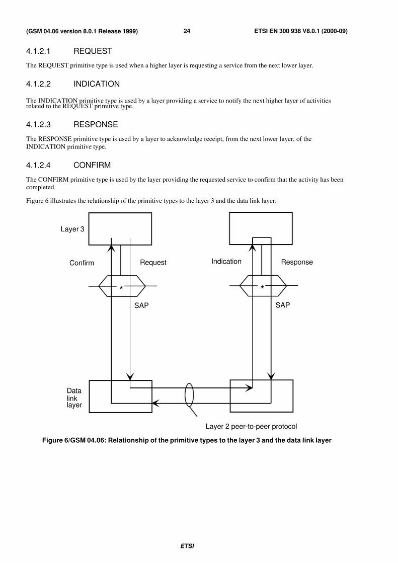
Figure 6 illustrates the relationship of the primitive types to the layer 3 and the data link layer.
*
Layer 3
Confirm Request
SAP
Datalinklayer
*
Response
SAP
Indication
Layer 2 peer-to-peer protocol
Figure 6/GSM 04.06: Relationship of the primitive types to the layer 3 and the data link layer
7/27/2019 MS & BTS Layer Specification
http://slidepdf.com/reader/full/ms-bts-layer-specification 25/59ETSI
ETSI EN 300 938 V8.0.1 (2000-09)25(GSM 04.06 version 8.0.1 Release 1999)
4.1.3 Parameter definition
4.1.3.1 Message unit
The message unit contains additional layer-to-layer information concerning actions and results associated with requests.In the case of the DATA and UNIT DATA primitives, the message unit contains the requesting layer peer-to-peer
messages For example, the DL-DATA message unit contains the layer 3 message unit; the PH-DATA message unit
contains the data link layer frame.
NOTE: The operations across the data link layer/layer 3 boundary shall be such that the layer sending the DATA
or UNIT DATA primitive can assume a temporal order of the bits within the message unit and that the
layer receiving the primitive can reconstruct the message with its assumed temporal order.
4.1.3.2 Channel type
Since the Dm channel procedures are distributed on several types of channel (CCCH, BCCH and various types of
DCCH), a parameter will be needed in order to distribute the layer 3 message units correctly on the various types of
channel. The control channel types to be used are defined in GSM 04.03.
4.1.3.3 Service Access Point
Since data links on different SAPIs may be multiplexed, the SAPI parameter is used to indicate the respective
association.
4.1.3.4 Release mode
The release mode parameter is used to enable the data link layer to operate in different release modes depending on
whether the data link is to be released in the normal way or that a local end release shall take place on command from
the layer 3. The values of the parameter are:
- normal;
- local end release.
4.1.3.5 Error cause
This parameters is used by the data link layer to report procedure error to layer 3. The following causes may be
reported:
- timer T200 expired (N200 +1) times: perform abnormal release;
- re-establishment request;
- unsolicited UA response;
- unsolicited DM response;
- unsolicited DM response, multiple frame established state: perform abnormal release;
- unsolicited supervisory response;
- sequence error: perform abnormal release;
- U frame with incorrect parameters;
- short L2 header type 1 not supported;
- short L2 header type 1 not applicable;
- S frame with incorrect parameters;
- I frame with incorrect use of M bit;
7/27/2019 MS & BTS Layer Specification
http://slidepdf.com/reader/full/ms-bts-layer-specification 26/59ETSI
ETSI EN 300 938 V8.0.1 (2000-09)26(GSM 04.06 version 8.0.1 Release 1999)
- I frame with incorrect length;
- frame not implemented;
- SABM command, multiple frame established state;
- SABM command with information field not allowed in this state.
4.1.3.6 Establish mode
This parameter is used in the MS to indicate to the data link layer the type of establishment that is required. The
parameter takes the following values:
- normal;
- contention resolution.
4.1.3.7 L2 header type
This parameter is used by higher layers to ask for application of a specific L2 header type; as values for the parameter,
only "short L2 header type 1" and "normal L2 header" are actually defined.
4.1.3.8 Priority
This parameter is used by the higher layers to indicate the priority of a Layer 3 message on SAPI 0 with multiple frame
operation. The parameter is not applicable to unacknowledged information transfer or to other SAPIs. The parameter
takes the following values:
- high;
- normal;
- low.
The parameter need not be included if the higher layers do not support the sending of low priority messages as defined
in GSM 04.08. If the parameter is not included, the data link layer shall assume a priority value of “normal”.
7/27/2019 MS & BTS Layer Specification
http://slidepdf.com/reader/full/ms-bts-layer-specification 27/59ETSI
ETSI EN 300 938 V8.0.1 (2000-09)27(GSM 04.06 version 8.0.1 Release 1999)
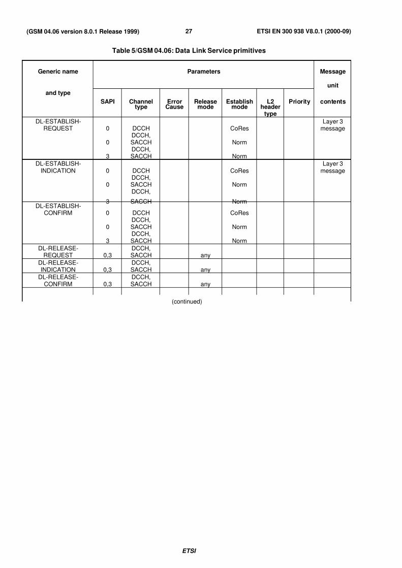
Table 5/GSM 04.06: Data Link Service primitives
Generic name Parameters Message
unit
and type
SAPI Channeltype
ErrorCause
Releasemode
Establishmode
L2header
type
Priority contents
DL-ESTABLISH-REQUEST 0 DCCH CoRes
Layer 3message
0DCCH,SACCH Norm
3DCCH,SACCH Norm
DL-ESTABLISH-INDICATION 0 DCCH CoRes
Layer 3message
0DCCH,SACCH Norm
3
DCCH,
SACCH NormDL-ESTABLISH-
CONFIRM 0 DCCH CoRes
0DCCH,SACCH Norm
3DCCH,SACCH Norm
DL-RELEASE-REQUEST 0,3
DCCH,SACCH any
DL-RELEASE-INDICATION 0,3
DCCH,SACCH any
DL-RELEASE-CONFIRM 0,3
DCCH,SACCH any
(continued)
7/27/2019 MS & BTS Layer Specification
http://slidepdf.com/reader/full/ms-bts-layer-specification 28/59ETSI
ETSI EN 300 938 V8.0.1 (2000-09)28(GSM 04.06 version 8.0.1 Release 1999)
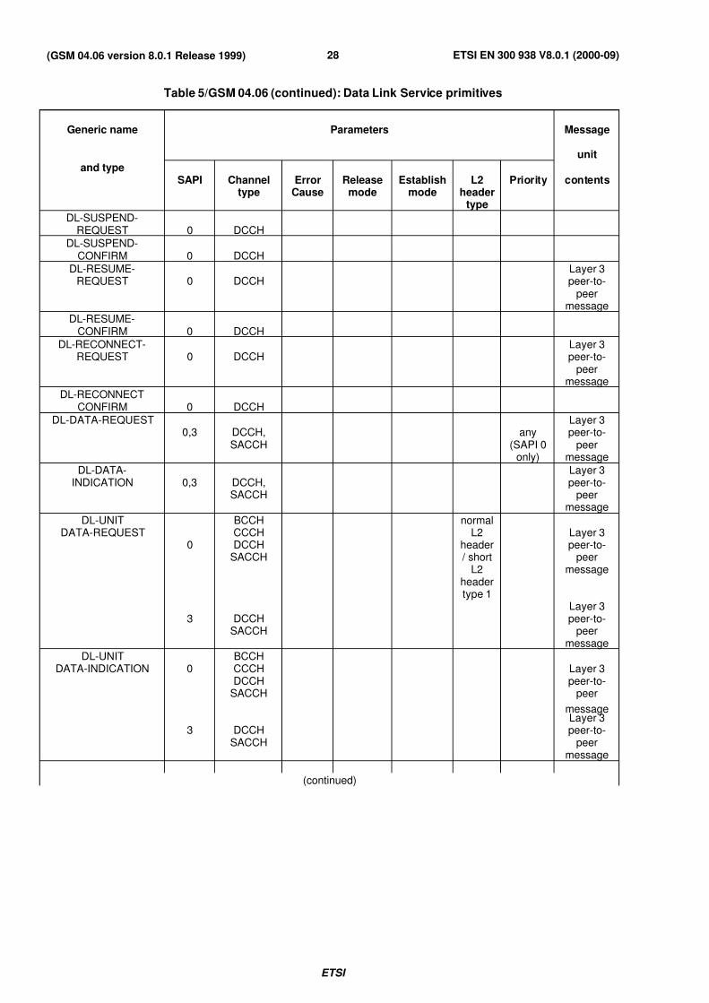
Table 5/GSM 04.06 (continued): Data Link Service primitives
Generic name Parameters Message
unit
and typeSAPI Channel
typeError
CauseRelease
modeEstablish
modeL2
headertype
Priority contents
DL-SUSPEND-REQUEST 0 DCCH
DL-SUSPEND-CONFIRM 0 DCCH
DL-RESUME-REQUEST 0 DCCH
Layer 3peer-to-
peermessage
DL-RESUME-CONFIRM 0 DCCH
DL-RECONNECT-REQUEST 0 DCCH
Layer 3peer-to-
peermessage
DL-RECONNECTCONFIRM 0 DCCH
DL-DATA-REQUEST0,3 DCCH,
SACCHany
(SAPI 0only)
Layer 3peer-to-
peermessage
DL-DATA-INDICATION 0,3 DCCH,
SACCH
Layer 3peer-to-
peermessage
DL-UNITDATA-REQUEST
0
BCCHCCCHDCCH
SACCH
normalL2
header / short
L2headertype 1
Layer 3peer-to-
peermessage
3 DCCHSACCH
Layer 3peer-to-
peermessage
DL-UNITDATA-INDICATION 0
BCCHCCCHDCCH
SACCH
Layer 3peer-to-
peer
message
3 DCCHSACCH
Layer 3peer-to-
peermessage
(continued)
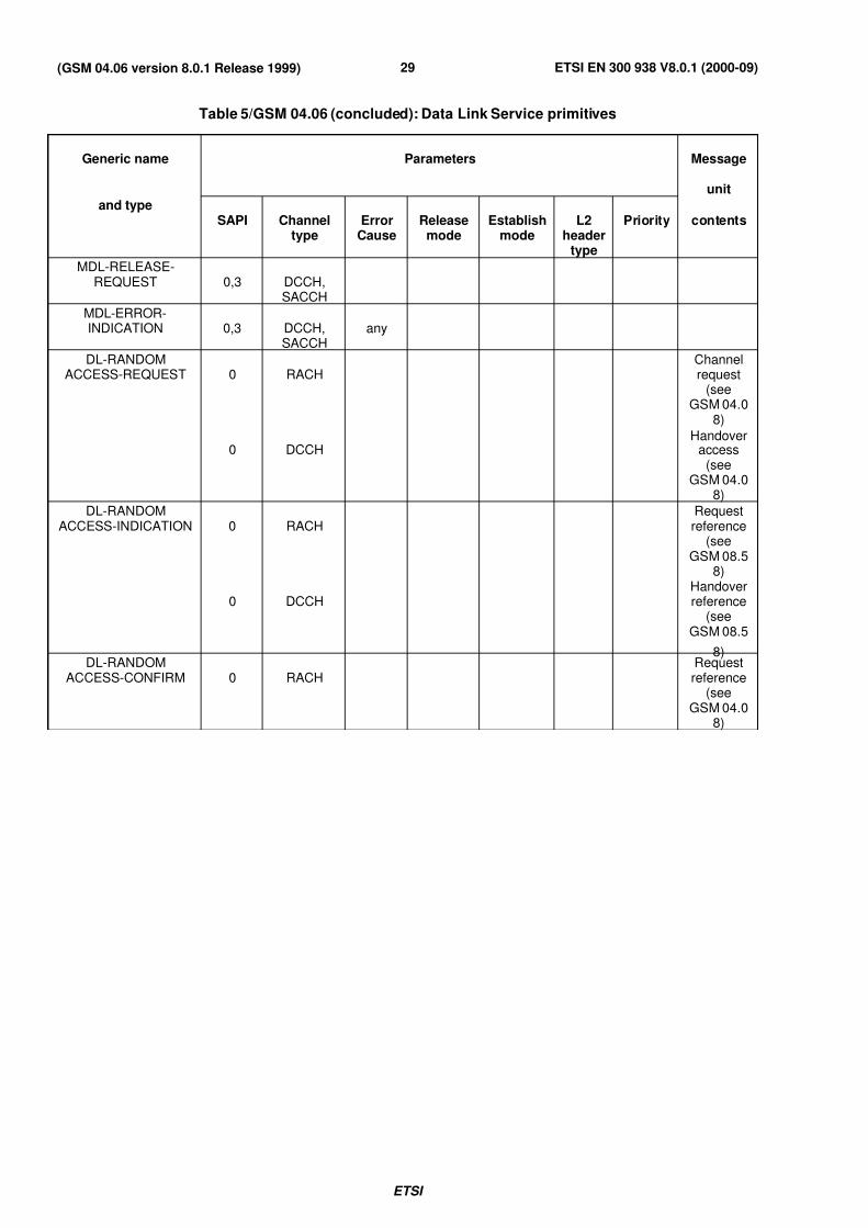
7/27/2019 MS & BTS Layer Specification
http://slidepdf.com/reader/full/ms-bts-layer-specification 29/59ETSI
ETSI EN 300 938 V8.0.1 (2000-09)29(GSM 04.06 version 8.0.1 Release 1999)
Table 5/GSM 04.06 (concluded): Data Link Service primitives
Generic name Parameters Message
unit
and typeSAPI Channel
typeError
CauseRelease
modeEstablish
modeL2
headertype
Priority contents
MDL-RELEASE-REQUEST 0,3 DCCH,
SACCH
MDL-ERROR-INDICATION 0,3 DCCH,
SACCHany
DL-RANDOMACCESS-REQUEST 0 RACH
Channelrequest
(seeGSM 04.0
8)
0 DCCHHandover
access(see
GSM 04.08)
DL-RANDOMACCESS-INDICATION 0 RACH
Requestreference
(seeGSM 08.5
8)
0 DCCHHandoverreference
(seeGSM 08.5
8)DL-RANDOM
ACCESS-CONFIRM 0 RACHRequest
reference(see
GSM 04.08)
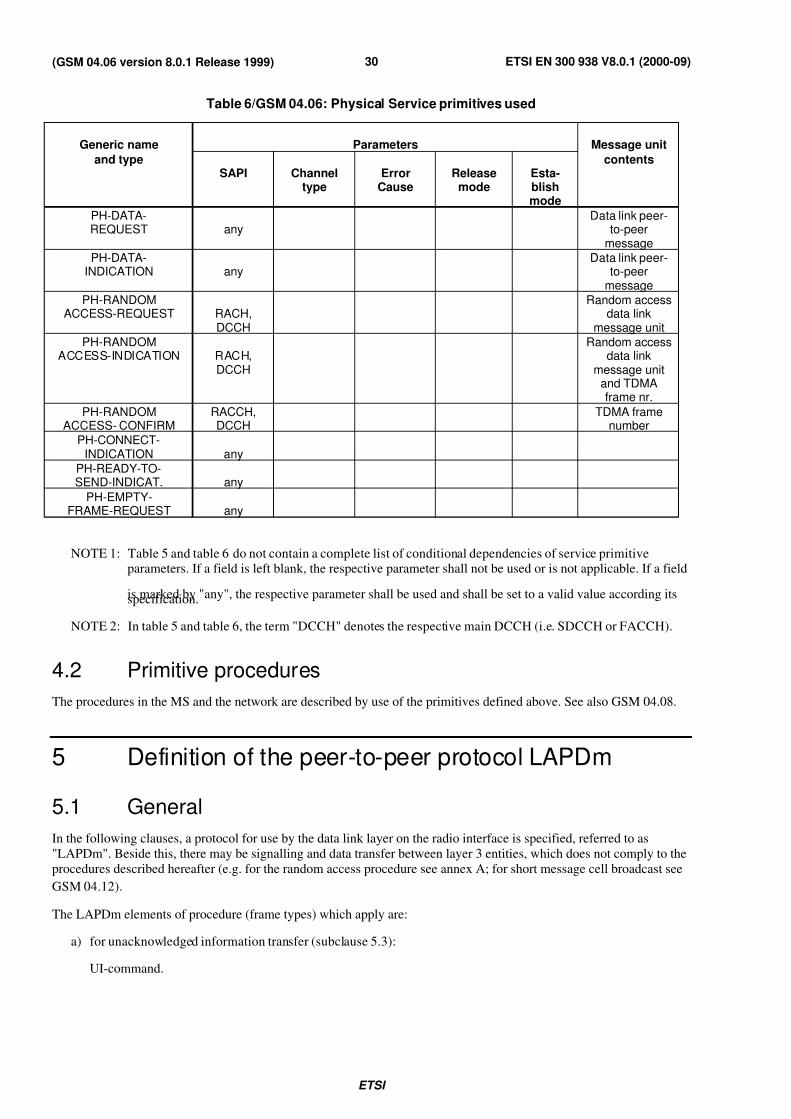
7/27/2019 MS & BTS Layer Specification
http://slidepdf.com/reader/full/ms-bts-layer-specification 30/59ETSI
ETSI EN 300 938 V8.0.1 (2000-09)30(GSM 04.06 version 8.0.1 Release 1999)
Table 6/GSM 04.06: Physical Service primitives used
Generic name Parameters Message unit
and typeSAPI Channel
typeError
CauseRelease
modeEsta-blishmode
contents
PH-DATA-REQUEST any
Data link peer-to-peer
message
PH-DATA-INDICATION any
Data link peer-to-peer
message
PH-RANDOMACCESS-REQUEST RACH,
DCCH
Random accessdata link
message unit
PH-RANDOMACCESS-INDICATION RACH,
DCCH
Random accessdata link
message unitand TDMAframe nr.
PH-RANDOMACCESS- CONFIRM
RACCH,DCCH
TDMA framenumber
PH-CONNECT-INDICATION any
PH-READY-TO-SEND-INDICAT. any
PH-EMPTY-FRAME-REQUEST any
NOTE 1: Table 5 and table 6 do not contain a complete list of conditional dependencies of service primitiveparameters. If a field is left blank, the respective parameter shall not be used or is not applicable. If a field
is marked by "any", the respective parameter shall be used and shall be set to a valid value according itsspecification.
NOTE 2: In table 5 and table 6, the term "DCCH" denotes the respective main DCCH (i.e. SDCCH or FACCH).
4.2 Primitive procedures
The procedures in the MS and the network are described by use of the primitives defined above. See also GSM 04.08.
5 Definition of the peer-to-peer protocol LAPDm
5.1 General
In the following clauses, a protocol for use by the data link layer on the radio interface is specified, referred to as
"LAPDm". Beside this, there may be signalling and data transfer between layer 3 entities, which does not comply to the
procedures described hereafter (e.g. for the random access procedure see annex A; for short message cell broadcast see
GSM 04.12).
The LAPDm elements of procedure (frame types) which apply are:
a) for unacknowledged information transfer (subclause 5.3):
UI-command.
7/27/2019 MS & BTS Layer Specification
http://slidepdf.com/reader/full/ms-bts-layer-specification 31/59ETSI
ETSI EN 300 938 V8.0.1 (2000-09)31(GSM 04.06 version 8.0.1 Release 1999)
b) for multiple frame acknowledged information transfer (subclauses 5.4 to 5.8):
SABM-command;
UA-response;
DM-response;
DISC-command;
RR-command/response;
RNR-command/response;
REJ-command/response;
I-command.
For the various channel types the following applies:
- BCCH; unacknowledged operation only;
- CCCH; unacknowledged operation only;
- all types of DCCH; unacknowledged operation and multiple frame acknowledged operation.
For acknowledged mode (multiple frame operation) on SAPI=0 and SAPI=3 , a special protocol operation shall be used
mandatorily, as specified in clause 6.
For handling of timers, the procedures and terminology of CCITT Recommendation Z.100 will be used, i.e.
set <timer name> means that:
a) if the timer is inactive, the timer becomes active, i e a timer value is associated with the timer and it starts
running;
b) if the timer is active, the timer is first reset, as in c) below and then set as in a) above;
reset <timer name> means that:
c) if the timer is active, the timer becomes inactive, i e the association with the timer value is lost and it stops
running;
d) if the timer is inactive, it remains inactive.
NOTE: The task set T200 shall be performed at the instant right before transmitting a frame, when the
PH-READY-TO-SEND primitive is received from the physical layer.
5.2 General Protocol Procedures5.2.1 Unacknowledged information transfer
Higher layers may ask for unacknowledged transmission transfer with normal L2 header; higher layers may also ask for
unacknowledged transmission transfer on SAPI 0 using short L2 header type 1.
When a protocol entity receives a valid UI frame, this requires no further response to the transmitting entity.
For unacknowledged information transfer with normal L2 header, the P/F bit is not used and shall be set to "0".
7/27/2019 MS & BTS Layer Specification
http://slidepdf.com/reader/full/ms-bts-layer-specification 32/59ETSI
ETSI EN 300 938 V8.0.1 (2000-09)32(GSM 04.06 version 8.0.1 Release 1999)
5.2.2 Acknowledged multiple frame information transfer
A data link layer entity receiving an SABM, DISC, RR, REJ or I command, shall respond to the originating entity by anappropriate response frame (as specified in subclauses 5.4 through 5.7 ) within the time limits given in subclause 5.9.
If the received command frame carries a P bit set to "1", the F bit in the corresponding response frame shall be set to
"1", too.
Frames containing SAPI values not used by the current version of the present document, shall be ignored without any
notification.
5.3 Procedures for unacknowledged information transfer
5.3.1 General
The procedures which apply to the transmission of information in unacknowledged operation are defined below.
No data link layer error recovery procedures are defined for unacknowledged operation.
5.3.2 Transmission of unacknowledged information
NOTE 1: The term "transmission of a UI frame" refers to the delivery of a UI frame by the data link layer to the
physical layer.
Unacknowledged information is passed to the data link layer by layer 3 using the primitive DL-UNIT
DATA-REQUEST. This DL-UNIT DATA-REQUEST specifies whether a short L2 header type 1 is to be used or not.
The layer 3 message unit shall be transmitted in a UI command frame.
Layer 2 shall construct a layer 2 message unit from the layer 3 message unit and pass it to layer 1 for transmission using
the primitive PH-DATA-REQ. The layer 2 message unit uses the frame type as defined in subclause 2.1.
If the layer 2 message unit contains a control field, the P bit shall be set to "0".
NOTE 2: On a DCCH, UI frames with the length indicator set to "0" may be used as fill frames, see
subclause 5.4.2.3.
5.3.3 Receipt of unacknowledged information
On receipt of a UI command frame with a SAPI which is supported by the receiver, the contents of the information field
shall be passed to the layer 3 entity identified by the SAPI using the data link layer to layer 3 primitive DL-UNIT
DATA-INDICATION. UI frames with invalid SAPI values shall be discarded. UI frames received with the length
indicator set to "0" shall be ignored.
5.4 Procedures for establishment and release of multiple frameoperation
5.4.1 Establishment of multiple frame operation
5.4.1.1 General
These procedures shall be used to establish multiple frame operation between the BS and a designated MS entity.
Layer 3 will initiate the establishment procedure after a physical channel supporting this type of operation
(see subclause 5.1) has been allocated to the MS.
NOTE: In order to avoid loss of layer 3 information if the SABM has to be retransmitted because the UA
response message is lost, the data link layer should be established when needed by the entity that willsend an I command frame. For SAPI 0 the data link is always established by the MS.
7/27/2019 MS & BTS Layer Specification
http://slidepdf.com/reader/full/ms-bts-layer-specification 33/59ETSI
ETSI EN 300 938 V8.0.1 (2000-09)33(GSM 04.06 version 8.0.1 Release 1999)
Two establishment procedures are specified:
- normal establishment where the SABM does not contain an information field. Layer 3 will indicate a request for
this type of establishment by the use of the DL-ESTABLISH-REQUEST primitive (subclauses 5.4.1.2 and
5.4.1.3);
- contention resolution where the SABM contains an information field. The procedure is always initiated by the
MS, i e the SABM is sent by the MS. Layer 3 will indicate a request for this type of establishment by the use of the DL-ESTABLISH-REQUEST primitive containing the layer 3 message unit (subclauses 5.4.1.4 and 5.4.1.5).
This procedure is only applicable for SAPI 0.
Re-establishment may be initiated, using the normal establishment procedure, as a result of the data link layer
procedure defined in subclause 5.6.
5.4.1.2 Normal establishment procedures
A data link layer entity shall initiate a request for the multiple frame operation to be set by transmitting the SetAsynchronous Balanced Mode (SABM) command with the P bit set to "1". Since the DL-ESTABLISH-REQUEST
primitive does not contain a layer 3 message unit, the length indicator, L, is set to "0".
All existing exception conditions shall be cleared, the retransmission counter shall be reset, and timer T200 shall be setright before transmitting a frame, when the PH-READY-TO-SEND primitive is received from the physical layer (timer
T200 is defined in subclause 5.8.1).
The establishment procedure implies the discard of any outstanding DL-DATA-REQUEST primitive which has been
invoked prior to the DL-ESTABLISH-REQUEST. It also implies the discard of any segmented layer 3 message unit for
which the last segment has not been received (see subclause 5.5.2 for the concatenation procedure).
All frames other than unnumbered frame formats received during the establishment procedures shall be ignored.
A data link layer entity receiving an SABM, if it is able to enter the multiple-frame-established state, shall:
- respond with an Unnumbered Acknowledgement (UA) response with the F bit set to the same binary value as the
P bit in the received SABM command, the same SAPI value as in the received SABM command, and with thelength indicator, L, set to "0";
- set the send state variable V(S), receive state variable V(R) and acknowledge state variable V(A) to 0;
- enter the multiple-frame-established state and inform the associated layer 3 entity using the primitive
DL- ESTABLISH-INDICATION;
- clear all existing exception conditions;
- clear an existing peer receiver busy condition.
If the data link layer entity is unable to enter the multiple-frame-established state, it shall respond to the SABM
command with a DM response with the F bit set to the same binary value as the P bit in the received SABM command.
Upon reception of the UA response with the F bit set to "1", the originator of the SABM command shall:
- reset timer T200;
- set the send state variable V(S), the receive state variable V(R) and the acknowledge state variable V(A) to 0;
- enter the multiple-frame-established state and inform the associated layer 3 entity using the primitive
DL- ESTABLISH-CONFIRM.
A UA response with the F bit set to "0" shall be ignored.
Upon reception of a DM response with F bit set to "1", the originator of the SABM command shall indicate this to the
layer 3 entity by means of the primitive DL-RELEASE- INDICATION and reset timer T200. DM responses with the
F bit set to "0" shall be ignored.
7/27/2019 MS & BTS Layer Specification
http://slidepdf.com/reader/full/ms-bts-layer-specification 34/59ETSI
ETSI EN 300 938 V8.0.1 (2000-09)34(GSM 04.06 version 8.0.1 Release 1999)
5.4.1.3 Procedure on expiry of timer T200: Normal establishment
If timer T200 expires before the UA or DM response is received, the data link layer entity shall:
- retransmit the SABM command as above;
- set timer T200 right before transmitting a frame, when the PH-READY-TO-SEND primitive is received from the
physical layer; and
- increment the retransmission counter.
After retransmission of the SABM command N200 times, the data link layer entity shall indicated this to the associatedlayer 3 entity by means of the primitive DL- RELEASE-INDICATION. Layer 3 shall also be notified by using the
primitive MDL-ERROR-INDICATION with the cause "timer T200 expired N200 + 1 times: perform abnormal
release".
The value of N200 is defined in subclause 5.8.2.
5.4.1.4 Contention resolution establishment procedure
This procedure is always initiated by the MS for establishing a data link in order to resolve contention after havingaccessed the BS on the RACH. Layer 3 decides when this establishment procedure is to be used and will request the
data link layer to initiate the procedure by a DL-ESTABLISH-REQUEST primitive containing the layer 3 message unit
and with the parameter established mode set to contention resolution.
The data link layer shall, however, ignore any such service request if it is not in the idle state when the request is
received.
The data link layer entity in the MS shall initiate the establishment by transmitting an SABM command with the P bitset to "1". The SABM command shall contain the layer 3 message unit received in the DL-ESTABLISH-REQUEST
primitive and the length indicator, L, shall be set to the appropriate value.
NOTE 1: According to clause 6, the contention resolution procedure is only permitted with SAPI value 0.
The information field of the SABM command shall be stored in the data link layer entity of the MS. The informationfield is removed when the data link layer enters the multiple frame established state or the idle state, see below.
All existing exception conditions shall be cleared, the retransmission counter shall be reset, and timer T200 shall be set
when right before transmitting a frame, when the PH-READY-TO-SEND primitive is received from the physical layer.
The peer data link layer entity in the BS receiving the SABM shall, if the entity is in the idle state and an "establishment
in progress" flag has not been set:
- set the "establishment in progress" flag;
- store the information field received in the SABM command;
- respond, at the earliest possible opportunity, with a UA response with:
- the same SAPI value as received in the SABM command;
- the F bit set to the same binary value as the P bit received in the SABM command;
- the length indicator, L, set to the same value as that contained in the SABM command;
- the same information field as that contained in the SABM command;
- set the send state variable V(S), the receive state variable V(R) and the acknowledge state variable V(A) to 0;
- enter the "contention resolution receiver" state and inform the layer 3 entity using the
DL-ESTABLISH- INDICATION primitive. The primitive shall contain the received layer 3 message unit;
- clear all existing exception conditions.
7/27/2019 MS & BTS Layer Specification
http://slidepdf.com/reader/full/ms-bts-layer-specification 35/59ETSI
ETSI EN 300 938 V8.0.1 (2000-09)35(GSM 04.06 version 8.0.1 Release 1999)
If an SABM command with an information field is received when the "establishment in progress" flag has been set, the
data link layer entity in the BS shall compare the stored information field with the information field received in the
SABM command. If they are not identical, the SABM command shall be ignored without any notification. If they are
identical, the data link entity shall respond, at the earliest possible opportunity, with a UA response with:
- the same SAPI value as received in the SABM command;
- the F bit set to the same binary value as the P bit contained in the SABM command;
- the length indicator, L, set to the same value as that contained in the SABM command;
- the stored information field.
NOTE 2: This case corresponds to a retransmission of the SABM command by the MS (see subclause 5.4.1.5).
NOTE 3: The specification is very different from the normal establishment procedure: in the latter case the
reception of a subsequent SABM frame triggers a re-establishment (see subclause 5.6).
The data link layer entity in the BS shall remove the "establishment in progress" flag and delete the stored information
field when:
- an I frame or supervisory frame is received. If the frame is in sequence, the data link layer entity shall enter themultiple frame established state and process the frame as specified for operation in the multiple frame
established state. If the frame is out of sequence, the BS shall initiate abnormal release using the procedure of
subclause 5.6;
- a release request is received from layer 3. In this case the data link layer entity shall enter the idle state if the
primitive received is DL-RELEASE-REQUEST or the null state if the primitive is MDL-RELEASE-REQUEST.
The procedure when awaiting acknowledgement in the MS is as follows:
Upon reception of a UA response containing an information field and with the F bit set to "1", the data link layer entity
in the MS shall compare the stored information field with the information field received in the UA response. If the two
fields are identical, the data link layer entity shall:
- reset timer T200;
- set the send state variable V(S), the receive state variable V(R) and the acknowledge state variable V(A) to 0;
- delete the stored information field;
- enter the multiple-frame-established state and inform the layer 3 entity using the DL-ESTABLISH-CONFIRM
primitive.
If the two fields are different, the data link layer entity shall:
- reset timer T200;
- delete the stored information field;
- enter the idle state and inform the layer 3 entity using the DL-RELEASE-INDICATION primitive.
All frames other than unnumbered frame formats received for the SAPI in use during the establishment procedures shall
be ignored.
The reception of unnumbered frames other than UA is treated as specified for the normal establishment case.
NOTE 4: In fact, there are no foreseen cases in which the network will send SABM, DISC or DM, but for sake of
completeness these occurrences are specified and must be treated.
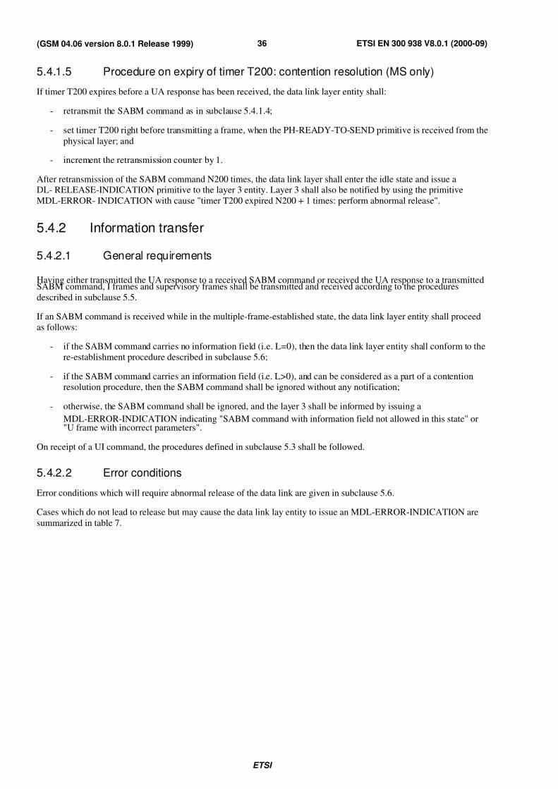
7/27/2019 MS & BTS Layer Specification
http://slidepdf.com/reader/full/ms-bts-layer-specification 36/59ETSI
ETSI EN 300 938 V8.0.1 (2000-09)36(GSM 04.06 version 8.0.1 Release 1999)
5.4.1.5 Procedure on expiry of timer T200: contention resolution (MS only)
If timer T200 expires before a UA response has been received, the data link layer entity shall:
- retransmit the SABM command as in subclause 5.4.1.4;
- set timer T200 right before transmitting a frame, when the PH-READY-TO-SEND primitive is received from the
physical layer; and
- increment the retransmission counter by 1.
After retransmission of the SABM command N200 times, the data link layer shall enter the idle state and issue aDL- RELEASE-INDICATION primitive to the layer 3 entity. Layer 3 shall also be notified by using the primitive
MDL-ERROR- INDICATION with cause "timer T200 expired N200 + 1 times: perform abnormal release".
5.4.2 Information transfer
5.4.2.1 General requirements
Having either transmitted the UA response to a received SABM command or received the UA response to a transmittedSABM command, I frames and supervisory frames shall be transmitted and received according to the procedures
described in subclause 5.5.
If an SABM command is received while in the multiple-frame-established state, the data link layer entity shall proceed
as follows:
- if the SABM command carries no information field (i.e. L=0), then the data link layer entity shall conform to the
re-establishment procedure described in subclause 5.6;
- if the SABM command carries an information field (i.e. L>0), and can be considered as a part of a contention
resolution procedure, then the SABM command shall be ignored without any notification;
- otherwise, the SABM command shall be ignored, and the layer 3 shall be informed by issuing a
MDL-ERROR-INDICATION indicating "SABM command with information field not allowed in this state" or"U frame with incorrect parameters".
On receipt of a UI command, the procedures defined in subclause 5.3 shall be followed.
5.4.2.2 Error conditions
Error conditions which will require abnormal release of the data link are given in subclause 5.6.
Cases which do not lead to release but may cause the data link lay entity to issue an MDL-ERROR-INDICATION are
summarized in table 7.
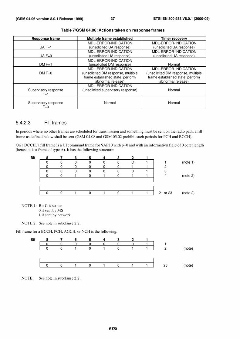
7/27/2019 MS & BTS Layer Specification
http://slidepdf.com/reader/full/ms-bts-layer-specification 37/59ETSI
ETSI EN 300 938 V8.0.1 (2000-09)37(GSM 04.06 version 8.0.1 Release 1999)
Table 7/GSM 04.06: Actions taken on response frames
Response frame Multiple frame established Timer recovery
UA F=1MDL-ERROR-INDICATION(unsolicited UA response)
MDL-ERROR-INDICATION(unsolicited UA response)
UA F=0MDL-ERROR-INDICATION(unsolicited UA response)
MDL-ERROR-INDICATION(unsolicited UA response)
DM F=1MDL-ERROR-INDICATION(unsolicited DM response) Normal
DM F=0MDL-ERROR-INDICATION
(unsolicited DM response, multipleframe established state: perform
abnormal release)
MDL-ERROR-INDICATION(unsolicited DM response, multiple
frame established state: performabnormal release)
Supervisory responseF=1
MDL-ERROR-INDICATION(unsolicited supervisory response) Normal
Supervisory responseF=0
Normal Normal
5.4.2.3 Fill frames
In periods where no other frames are scheduled for transmission and something must be sent on the radio path, a fill
frame as defined below shall be sent (GSM 04.08 and GSM 05.02 prohibit such periods for PCH and BCCH).
On a DCCH, a fill frame is a UI command frame for SAPI 0 with p=0 and with an information field of 0 octet length
(hence, it is a frame of type A). It has the following structure:
Bit 8 7 6 5 4 3 2 1
0 0 0 0 0 0 C 1 1 (note 1)
0 0 0 0 0 0 1 1 2
0 0 0 0 0 0 0 1 3
0 0 1 0 1 0 1 1 4 (note 2)
0 0 1 0 1 0 1 1 21 or 23 (note 2)
NOTE 1: Bit C is set to:
0 if sent by MS
1 if sent by network.
NOTE 2: See note in subclause 2.2.
Fill frame for a BCCH, PCH, AGCH, or NCH is the following:
Bit 8 7 6 5 4 3 2 10 0 0 0 0 0 0 1 1
0 0 1 0 1 0 1 1 2 (note)
0 0 1 0 1 0 1 1 23 (note)
NOTE: See note in subclause 2.2.
7/27/2019 MS & BTS Layer Specification
http://slidepdf.com/reader/full/ms-bts-layer-specification 38/59ETSI
ETSI EN 300 938 V8.0.1 (2000-09)38(GSM 04.06 version 8.0.1 Release 1999)
5.4.3 Suspension and resumption of multiple frame operation
5.4.3.1 General
These procedures shall be used in a MS entity to suspend the uplink multiple frame operation for SAPI=0 during achange of dedicated channels (dedicated channel assignment or handover procedure on layer 3) and to resume the
operation after the new physical channel has been connected. The purpose of these procedures is to provide a
mechanism for reliably avoiding message loss during a change of dedicated channels. The procedures are only
described for the case where the window size is one; it should, however, be obvious how to adapt them to larger
window sizes.
As the procedures may delay the actual channel change, they shall only be used to protect layer 3 messages pertaining
to SAPI=0. Applications using the multiple frame established service on SAPIs other than 0 are expected to cope with
message loss or duplication autonomously, i.e. on layers above layer 2.
Both layer 3 procedures, dedicated channel assignment and handover, are initiated and controlled by a network entity
(BSS or MSC). This entity therefore will suspend the flow of layer 3 messages towards the MS after the
ASSIGNMENT or HANDOVER COMMAND message has been issued. When the data link on the new channel hasbeen established, the message flow may resume. Obviously, no provisions in layer 2 are needed on the network side to
prevent message loss or duplication on the downlink during channel change.
In the following, the procedures in the MS are described. For the description of the procedures, a conceptual
configuration of a send queue, a send buffer and a transmit buffer are assumed.
In order to ease the description of the procedures in the MS, it is assumed that any layer 3 message passed to layer 2 via
SAPI 0 in DL-DATA-REQUEST or DL-UNIT-DATA primitive is first placed in the send queue. The layer 2 entity will
take out the messages "first in-first out" and put them into a send buffer. The send buffer can hold no more than one
layer 3 message at a time. From the contents of the send buffer, an I frame or UI frame is constructed, only one at a
time, and placed in a transmit buffer. (If the layer 3 message needs to be segmented, then this last step will be
performed several times). The frame is then transmitted.
Upon transmission and after it has been acknowledged if it has been an I frame, the transmit buffer is cleared and filled
with the next frame. When the contents of the send buffer have been transmitted and acknowledged, the send buffer iscleared and filled with the next layer 3 message from the send queue.
5.4.3.2 Suspension
A layer 3 entity in the MS shall indicate a request for the suspension of multiple frame operation by use of the
DL-SUSPEND-REQUEST primitive. The layer 2 entity, upon receipt of this primitive, shall act as follows:
No further layer 3 messages shall be taken from the send queue for SAPI=0.
- If there is a layer 3 message in the send buffer which has not yet been transmitted, it shall not be transmitted. The
contents of the send buffer shall be put back to the first position of the send queue. The send and transmit buffers
shall be cleared. A layer 3 message is considered to be transmitted as soon as its final segment has been
transmitted at least once; it need not yet have been acknowledged. (This ensures that all segments of a segmented
and possibly partly transmitted layer 3 message will be transmitted on the new channel. Those segments already
transmitted and received on the network side will be discarded by the network upon release of the old channel
because the layer 3 message is not yet complete).
- If there is a layer 3 message in the send buffer, the last segment of which has been transmitted but is not yet fully
acknowledged, i.e. the frame carrying the last segment of the message has been transmitted but is not yet
acknowledged, then the contents of the send buffer shall be put back to the first position of the send queue and
the send and transmit buffers shall be cleared.
- The layer 2 entity shall then return a DL-SUSPEND-CONFIRM primitive to layer 3.
The data link layer entity is now in the suspended state. the only difference to the multiple frame established state is thatno UI frames and no I frames are transmitted (all SAPIs).
The MS may now change to the new channel.
7/27/2019 MS & BTS Layer Specification
http://slidepdf.com/reader/full/ms-bts-layer-specification 39/59ETSI
ETSI EN 300 938 V8.0.1 (2000-09)39(GSM 04.06 version 8.0.1 Release 1999)
5.4.3.3 Resumption
5.4.3.3.1 Procedure after channel change
This procedure is initiated by the DL-RESUME primitive. A data link layer entity shall initiate a request for the
multiple frame operation by transmitting the SABM command.
All existing exception conditions shall be cleared and the retransmission counter shall be reset. All outstanding
DL-DATA- REQUEST primitives and layer 3 message units, which are not fully acknowledged, shall be saved. Any
segmented layer 3 message unit, for which the last segment has not been received shall be discarded.
The send buffer is cleared.
A layer 3 message included in the DL-RESUME-REQUEST primitive (in general, ASSIGNMENT COMPLETE or
HANDOVER COMPLETE) is put into the send buffer for transmission in acknowledged mode.
Upon reception of UA response the data link layer shall:
- reset T200;
- set send variable V(S), the receive state variable V(R) and the acknowledge state variable V(A) to 0;
- enter the multiple established state;
- confirm establishment to layer 3 using DL-ESTABLISH-CONFIRM;
- send the layer 3 message unit passed together with the DL-RESUME primitive.
The data link layer shall then continue normal operation.
5.4.3.3.2 Procedure after returning to the old channel (MS only)
This procedure is initiated by the DL-RECONNECT primitive. A data link layer entity shall initiate a request for themultiple frame operation by transmitting the SABM command. All existing exception conditions shall be cleared and
the retransmission counter shall be reset. All outstanding DL-DATA-REQUEST primitives and layer 3 message units,which are not fully acknowledged, shall be saved; this does not include a message carried by a possible previous
DL-RESUME-REQUEST. Any segmented layer 3 message units, for which the last segment has not been received
shall be discarded.
The send buffer is cleared.
A layer 3 message included in the DL-RECONNECT-REQUEST primitive (in general, ASSIGNMENT FAILURE or
HANDOVER FAILURE) is put into the send buffer for transmission in acknowledge mode.
Upon reception of a UA response the data link layer shall:
- reset T200;
- set send state variable V(S), the receive state variable V(R) and the acknowledge state variable V(A) to 0;
- enter the multiple frame established state;
- confirm establishment to layer 3 using DL-ESTABLISH-CONFIRM;
- send the layer 3 message unit passed together with DL-RECONNECT-REQUEST primitive.
The data link layer shall then continue normal operation.
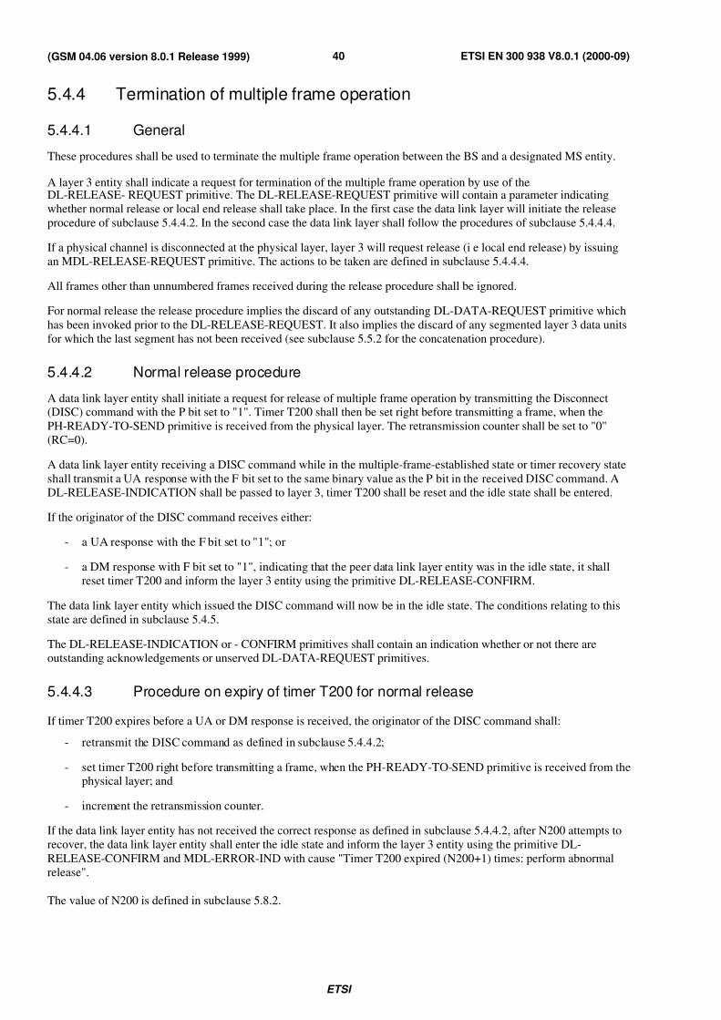
7/27/2019 MS & BTS Layer Specification
http://slidepdf.com/reader/full/ms-bts-layer-specification 40/59ETSI
ETSI EN 300 938 V8.0.1 (2000-09)40(GSM 04.06 version 8.0.1 Release 1999)
5.4.4 Termination of multiple frame operation
5.4.4.1 General
These procedures shall be used to terminate the multiple frame operation between the BS and a designated MS entity.
A layer 3 entity shall indicate a request for termination of the multiple frame operation by use of theDL-RELEASE- REQUEST primitive. The DL-RELEASE-REQUEST primitive will contain a parameter indicating
whether normal release or local end release shall take place. In the first case the data link layer will initiate the release
procedure of subclause 5.4.4.2. In the second case the data link layer shall follow the procedures of subclause 5.4.4.4.
If a physical channel is disconnected at the physical layer, layer 3 will request release (i e local end release) by issuing
an MDL-RELEASE-REQUEST primitive. The actions to be taken are defined in subclause 5.4.4.4.
All frames other than unnumbered frames received during the release procedure shall be ignored.
For normal release the release procedure implies the discard of any outstanding DL-DATA-REQUEST primitive which
has been invoked prior to the DL-RELEASE-REQUEST. It also implies the discard of any segmented layer 3 data units
for which the last segment has not been received (see subclause 5.5.2 for the concatenation procedure).
5.4.4.2 Normal release procedure
A data link layer entity shall initiate a request for release of multiple frame operation by transmitting the Disconnect(DISC) command with the P bit set to "1". Timer T200 shall then be set right before transmitting a frame, when the
PH-READY-TO-SEND primitive is received from the physical layer. The retransmission counter shall be set to "0"
(RC=0).
A data link layer entity receiving a DISC command while in the multiple-frame-established state or timer recovery state
shall transmit a UA response with the F bit set to the same binary value as the P bit in the received DISC command. A
DL-RELEASE-INDICATION shall be passed to layer 3, timer T200 shall be reset and the idle state shall be entered.
If the originator of the DISC command receives either:
- a UA response with the F bit set to "1"; or
- a DM response with F bit set to "1", indicating that the peer data link layer entity was in the idle state, it shall
reset timer T200 and inform the layer 3 entity using the primitive DL-RELEASE-CONFIRM.
The data link layer entity which issued the DISC command will now be in the idle state. The conditions relating to this
state are defined in subclause 5.4.5.
The DL-RELEASE-INDICATION or - CONFIRM primitives shall contain an indication whether or not there are
outstanding acknowledgements or unserved DL-DATA-REQUEST primitives.
5.4.4.3 Procedure on expiry of timer T200 for normal release
If timer T200 expires before a UA or DM response is received, the originator of the DISC command shall:
- retransmit the DISC command as defined in subclause 5.4.4.2;
- set timer T200 right before transmitting a frame, when the PH-READY-TO-SEND primitive is received from thephysical layer; and
- increment the retransmission counter.
If the data link layer entity has not received the correct response as defined in subclause 5.4.4.2, after N200 attempts to
recover, the data link layer entity shall enter the idle state and inform the layer 3 entity using the primitive DL-
RELEASE-CONFIRM and MDL-ERROR-IND with cause "Timer T200 expired (N200+1) times: perform abnormal
release".
The value of N200 is defined in subclause 5.8.2.

7/27/2019 MS & BTS Layer Specification
http://slidepdf.com/reader/full/ms-bts-layer-specification 41/59ETSI
ETSI EN 300 938 V8.0.1 (2000-09)41(GSM 04.06 version 8.0.1 Release 1999)
5.4.4.4 Local end release procedure
When receiving a DL-RELEASE-REQUEST primitive from layer 3 with the release mode parameter set to "local end
release", the data link layer shall in all states:
- return a DL-RELEASE-CONFIRM primitive;
- enter the idle state without issuing any commands to the peer entity.
The DL-RELEASE-CONFIRM primitive shall contain an indication whether or not there are outstanding
acknowledgements or unserved DL-DATA-REQUEST primitives.
When receiving an MDL-RELEASE-REQUEST primitive, the data link layer entity, when in the idle state, shall enter
the null state. In all other states the data link layer shall:
- if there is no outstanding DL-RELEASE-REQUEST primitive, issue a DL-RELEASE-INDICATION primitive
to layer 3;
- if there is an outstanding DL-RELEASE-REQUEST primitive, issue a DL-RELEASE-CONFIRM primitive tolayer 3;
- enter the null state without issuing any commands to the peer entity.
NOTE: The null state is the state, as viewed from the data link layer, where no physical resource exists for the
specific data link layer entity.
5.4.5 Idle state
While in the idle state:
- the receipt of a DISC command shall result in the transmission of a DM response with the F bit set to the value
of the received P bit;
- the receipt of an I frame or supervisory frame with the P bit set to "1" shall result in the transmission of a DM
response with the F bit set to "1" (as defined in subclause 5.2.2);
- the content of any received I frame shall be discarded;
- on receipt of an SABM command, the procedures defined in subclause 5.4.1 shall be followed;
- on receipt of UI commands, the procedures defined in subclause 5.3 shall be followed;
- all other frame types shall be discarded.
5.4.6 Collision of unnumbered commands and responses
Collision situations shall be resolved in the following way:
5.4.6.1 Identical transmitted and received commands
If the transmitted and received unnumbered commands (SABM or DISC) are the same, the data link layer entities shall
send the UA response at the earliest possible opportunity. The indicated state shall be entered after receiving the UA
response. The data link layer entities shall each notify its respective layer 3 entity by means of the appropriate confirm
primitive, i.e. DL-ESTABLISH-CONFIRM or DL-RELEASE-CONFIRM.
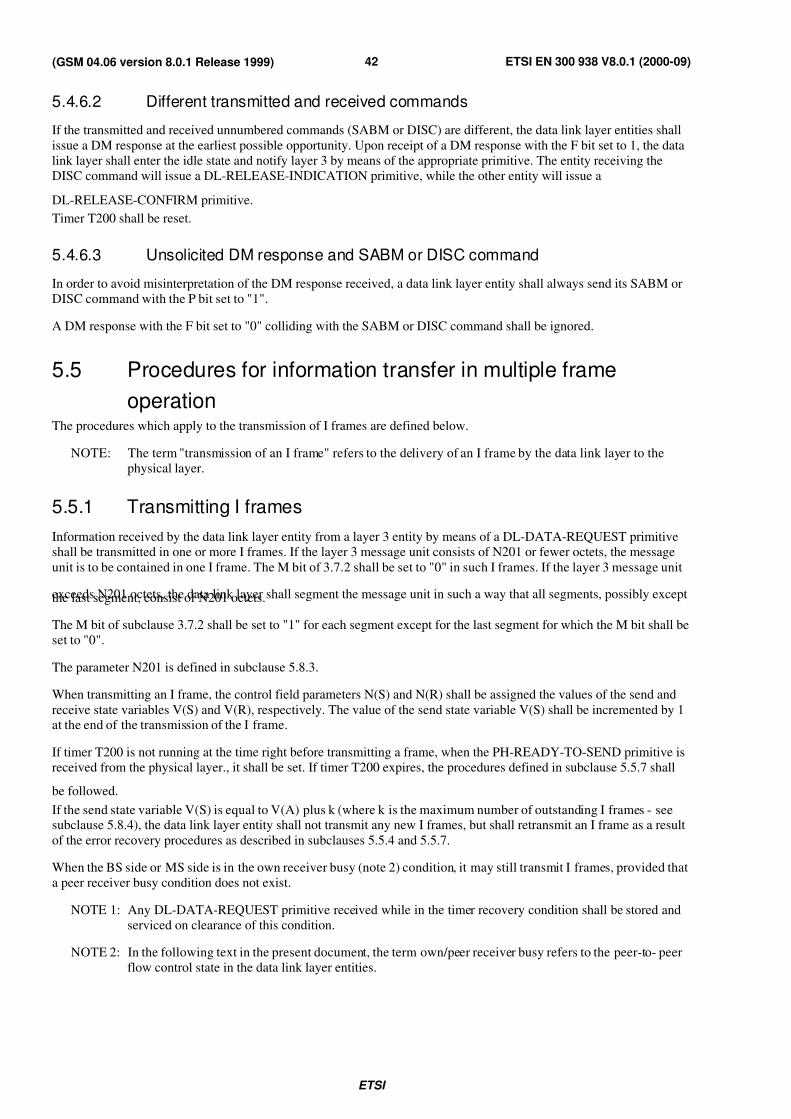
7/27/2019 MS & BTS Layer Specification
http://slidepdf.com/reader/full/ms-bts-layer-specification 42/59ETSI
ETSI EN 300 938 V8.0.1 (2000-09)42(GSM 04.06 version 8.0.1 Release 1999)
5.4.6.2 Different transmitted and received commands
If the transmitted and received unnumbered commands (SABM or DISC) are different, the data link layer entities shall
issue a DM response at the earliest possible opportunity. Upon receipt of a DM response with the F bit set to 1, the data
link layer shall enter the idle state and notify layer 3 by means of the appropriate primitive. The entity receiving the
DISC command will issue a DL-RELEASE-INDICATION primitive, while the other entity will issue a
DL-RELEASE-CONFIRM primitive.
Timer T200 shall be reset.
5.4.6.3 Unsolicited DM response and SABM or DISC command
In order to avoid misinterpretation of the DM response received, a data link layer entity shall always send its SABM or
DISC command with the P bit set to "1".
A DM response with the F bit set to "0" colliding with the SABM or DISC command shall be ignored.
5.5 Procedures for information transfer in multiple frame
operationThe procedures which apply to the transmission of I frames are defined below.
NOTE: The term "transmission of an I frame" refers to the delivery of an I frame by the data link layer to the
physical layer.
5.5.1 Transmitting I frames
Information received by the data link layer entity from a layer 3 entity by means of a DL-DATA-REQUEST primitive
shall be transmitted in one or more I frames. If the layer 3 message unit consists of N201 or fewer octets, the message
unit is to be contained in one I frame. The M bit of 3.7.2 shall be set to "0" in such I frames. If the layer 3 message unit
exceeds N201 octets, the data link layer shall segment the message unit in such a way that all segments, possibly exceptthe last segment, consist of N201 octets.
The M bit of subclause 3.7.2 shall be set to "1" for each segment except for the last segment for which the M bit shall be
set to "0".
The parameter N201 is defined in subclause 5.8.3.
When transmitting an I frame, the control field parameters N(S) and N(R) shall be assigned the values of the send and
receive state variables V(S) and V(R), respectively. The value of the send state variable V(S) shall be incremented by 1at the end of the transmission of the I frame.
If timer T200 is not running at the time right before transmitting a frame, when the PH-READY-TO-SEND primitive is
received from the physical layer., it shall be set. If timer T200 expires, the procedures defined in subclause 5.5.7 shall
be followed.
If the send state variable V(S) is equal to V(A) plus k (where k is the maximum number of outstanding I frames - seesubclause 5.8.4), the data link layer entity shall not transmit any new I frames, but shall retransmit an I frame as a result
of the error recovery procedures as described in subclauses 5.5.4 and 5.5.7.
When the BS side or MS side is in the own receiver busy (note 2) condition, it may still transmit I frames, provided that
a peer receiver busy condition does not exist.
NOTE 1: Any DL-DATA-REQUEST primitive received while in the timer recovery condition shall be stored and
serviced on clearance of this condition.
NOTE 2: In the following text in the present document, the term own/peer receiver busy refers to the peer-to- peer
flow control state in the data link layer entities.

7/27/2019 MS & BTS Layer Specification
http://slidepdf.com/reader/full/ms-bts-layer-specification 43/59ETSI
ETSI EN 300 938 V8.0.1 (2000-09)43(GSM 04.06 version 8.0.1 Release 1999)
5.5.2 Receiving I frames
When a data link layer entity is not in an own receiver busy condition and receives a valid I frame whose send sequencenumber is equal to the current receive state variable V(R), the data link layer entity shall:
- if the M bit is set to "0", concatenate it with previously received frames with the M bit set to "1", if any, and pass
the complete layer 3 message unit to the layer 3 entity using the primitive DL-DATA-INDICATION;
- if the M bit is set to "1", store the information field of the frame and concatenate it with previously received
frames with the M bit set to "1", if any (Note: no information is passed to the layer 3 entity);
- increment by 1 its receive state variable V(R), and act as indicated below.
NOTE: The M bit is defined in subclause 3.7.2.
5.5.2.1 P bit of the received I frame set to "1"
If the P bit of the received I frame was set to "1", the data link layer entity shall respond to its peer in one of the
following ways:
- if the data link layer entity receiving the I frame is still not in an own receiver busy condition, it shall send an RRresponse with the F bit set to "1";
- if the data link layer entity receiving the I frame enters the own receiver busy condition upon the receipt of the
I frame, it shall send an RNR response with the F bit set to "1".
5.5.2.2 P bit of the received I frame set to "0"
If the P bit of the received I frame was set to "0" and:
a) if the data link layer entity is still not in an own receiver busy condition:
- if no I frame is available for transmission or if an I frame is available for transmission but a peer receiver
busy condition exists, the data link layer entity shall transmit an RR response with the F bit set to "0"; or
- if an I frame is available for transmission and no peer receiver busy condition exists, the data link layer entity
shall transmit the I frame with the value of N(R) set to the current value of V(R) as defined in subclause 5.5.1
(this I frame then acknowledges the receipt of an I frame); or
b) if, on receipt of this I frame, the data link layer entity is now in an own receiver busy condition, it shall transmit
an RNR response with the F bit set to "0".
When the data link layer entity is in an own receiver busy condition, it shall process any received I frame according tosubclause 5.5.6.
NOTE 1: The term "available for transmission" should be interpreted to mean available for transmission at the
instant when the physical layer is ready to transmit the next frame. Making this decision as close as
possible to that instant, will ensure minimum delay in the transmission of I frames.
NOTE 2: Any I frame received in the timer recovery condition shall be handled as stated above.
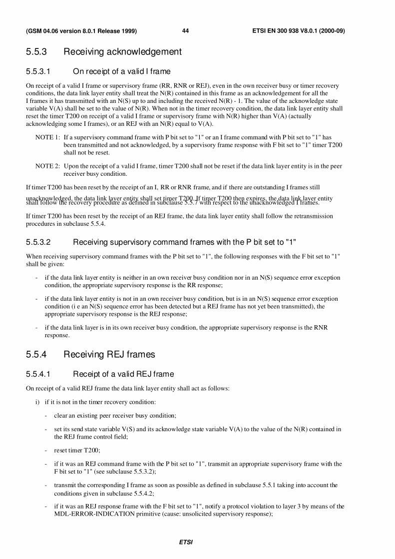
7/27/2019 MS & BTS Layer Specification
http://slidepdf.com/reader/full/ms-bts-layer-specification 44/59ETSI
ETSI EN 300 938 V8.0.1 (2000-09)44(GSM 04.06 version 8.0.1 Release 1999)
5.5.3 Receiving acknowledgement
5.5.3.1 On receipt of a valid I frame
On receipt of a valid I frame or supervisory frame (RR, RNR or REJ), even in the own receiver busy or timer recoveryconditions, the data link layer entity shall treat the N(R) contained in this frame as an acknowledgement for all the
I frames it has transmitted with an N(S) up to and including the received N(R) - 1. The value of the acknowledge state
variable V(A) shall be set to the value of N(R). When not in the timer recovery condition, the data link layer entity shall
reset the timer T200 on receipt of a valid I frame or supervisory frame with N(R) higher than V(A) (actually
acknowledging some I frames), or an REJ with an N(R) equal to V(A).
NOTE 1: If a supervisory command frame with P bit set to "1" or an I frame command with P bit set to "1" has
been transmitted and not acknowledged, by a supervisory frame response with F bit set to "1" timer T200
shall not be reset.
NOTE 2: Upon the receipt of a valid I frame, timer T200 shall not be reset if the data link layer entity is in the peer
receiver busy condition.
If timer T200 has been reset by the receipt of an I, RR or RNR frame, and if there are outstanding I frames still
unacknowledged, the data link layer entity shall set timer T200. If timer T200 then expires, the data link layer entityshall follow the recovery procedure as defined in subclause 5.5.7 with respect to the unacknowledged I frames.
If timer T200 has been reset by the receipt of an REJ frame, the data link layer entity shall follow the retransmission
procedures in subclause 5.5.4.
5.5.3.2 Receiving supervisory command frames with the P bit set to "1"
When receiving supervisory command frames with the P bit set to "1", the following responses with the F bit set to "1"
shall be given:
- if the data link layer entity is neither in an own receiver busy condition nor in an N(S) sequence error exception
condition, the appropriate supervisory response is the RR response;
- if the data link layer entity is not in an own receiver busy condition, but is in an N(S) sequence error exception
condition (i e an N(S) sequence error has been detected but a REJ frame has not yet been transmitted), the
appropriate supervisory response is the REJ response;
- if the data link layer is in its own receiver busy condition, the appropriate supervisory response is the RNR
response.
5.5.4 Receiving REJ frames
5.5.4.1 Receipt of a valid REJ frame
On receipt of a valid REJ frame the data link layer entity shall act as follows:
i) if it is not in the timer recovery condition:
- clear an existing peer receiver busy condition;
- set its send state variable V(S) and its acknowledge state variable V(A) to the value of the N(R) contained in
the REJ frame control field;
- reset timer T200;
- if it was an REJ command frame with the P bit set to "1", transmit an appropriate supervisory frame with the
F bit set to "1" (see subclause 5.5.3.2);
- transmit the corresponding I frame as soon as possible as defined in subclause 5.5.1 taking into account the
conditions given in subclause 5.5.4.2;
- if it was an REJ response frame with the F bit set to "1", notify a protocol violation to layer 3 by means of theMDL-ERROR-INDICATION primitive (cause: unsolicited supervisory response);
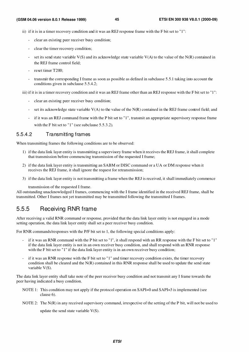
7/27/2019 MS & BTS Layer Specification
http://slidepdf.com/reader/full/ms-bts-layer-specification 45/59ETSI
ETSI EN 300 938 V8.0.1 (2000-09)45(GSM 04.06 version 8.0.1 Release 1999)
ii) if it is in a timer recovery condition and it was an REJ response frame with the F bit set to "1":
- clear an existing peer receiver busy condition;
- clear the timer recovery condition;
- set its send state variable V(S) and its acknowledge state variable V(A) to the value of the N(R) contained in
the REJ frame control field;
- reset timer T200;
- transmit the corresponding I frame as soon as possible as defined in subclause 5.5.1 taking into account the
conditions given in subclause 5.5.4.2;
iii) if it is in a timer recovery condition and it was an REJ frame other than an REJ response with the F bit set to "1":
- clear an existing peer receiver busy condition;
- set its acknowledge state variable V(A) to the value of the N(R) contained in the REJ frame control field; and
- if it was an REJ command frame with the P bit set to "1", transmit an appropriate supervisory response frame
with the F bit set to "1" (see subclause 5.5.3.2).
5.5.4.2 Transmitting frames
When transmitting frames the following conditions are to be observed:
1) if the data link layer entity is transmitting a supervisory frame when it receives the REJ frame, it shall complete
that transmission before commencing transmission of the requested I frame;
2) if the data link layer entity is transmitting an SABM or DISC command or a UA or DM response when itreceives the REJ frame, it shall ignore the request for retransmission;
3) if the data link layer entity is not transmitting a frame when the REJ is received, it shall immediately commence
transmission of the requested I frame.
All outstanding unacknowledged I frames, commencing with the I frame identified in the received REJ frame, shall be
transmitted. Other I frames not yet transmitted may be transmitted following the transmitted I frames.
5.5.5 Receiving RNR frame
After receiving a valid RNR command or response, provided that the data link layer entity is not engaged in a mode
setting operation, the data link layer entity shall set a peer receiver busy condition.
For RNR commands/responses with the P/F bit set to 1, the following special conditions apply:
- if it was an RNR command with the P bit set to "1", it shall respond with an RR response with the F bit set to "1"
if the data link layer entity is not in an own receiver busy condition, and shall respond with an RNR response
with the F bit set to "1" if the data link layer entity is in an own receiver busy condition;
- if it was an RNR response with the F bit set to "1" and timer recovery condition exists, the timer recovery
condition shall be cleared and the N(R) contained in this RNR response shall be used to update the send state
variable V(S).
The data link layer entity shall take note of the peer receiver busy condition and not transmit any I frame towards the
peer having indicated a busy condition.
NOTE 1: This condition may not apply if the protocol operation on SAPI=0 and SAPI=3 is implemented (see
clause 6).
NOTE 2: The N(R) in any received supervisory command, irrespective of the setting of the P bit, will not be used to
update the send state variable V(S).
7/27/2019 MS & BTS Layer Specification
http://slidepdf.com/reader/full/ms-bts-layer-specification 46/59ETSI
ETSI EN 300 938 V8.0.1 (2000-09)46(GSM 04.06 version 8.0.1 Release 1999)
The data link layer entity shall then:
- treat the receive sequence number N(R) contained in the received RNR frame as an acknowledgement for all the
I frames that have been transmitted or retransmitted with an N(S) up to and including N(R) -1, and set its
acknowledge state variable V(A) to the value of the N(R) contained in the RNR frame; and
- set timer T200 unless a supervisory response frame with the F bit set to "1" is still expected.
If timer T200 expires, the data link layer entity shall:
- if it is not yet in a timer recovery condition, enter a timer recovery condition, and set the retransmission count
variable to 0;
- if it is already in a timer recovery condition, add one to its retransmission count variable.
The data link layer entity shall then:
- if the value of the retransmission count variable is less than N200, transmit an appropriate supervisory command
(see subclause 5.5.3.2) with the P bit set to "1", and set timer T200 right before transmitting a frame, when the
PH-READY-TO-SEND primitive is received from the physical layer; or
- if the value of the retransmission count variable is equal to N200, it shall initiate the abnormal release proceduredescribed in subclause 5.6. Layer 3 shall be notified via the MDL-ERROR-INDICATION primitive with cause
"timer T200 expired N200 + 1 times: perform abnormal release".
The peer data link layer entity receiving the supervisory frame with the P bit set to "1" shall respond, at the earliestopportunity, with the appropriate supervisory response frame (see subclause 5.5.3.2) with the F bit set to "1", to indicate
whether or not its own receiver busy condition still exists.
Upon receipt of the supervisory response with the F bit set to "1", the data link layer entity shall reset timer T200, and:
- if the response is an RR or REJ response, the peer receiver busy condition is cleared and the data link layer entity
may transmit new I frames or retransmit I frames as defined in subclauses 5.5.1 or 5.5.4, respectively; or
- if the response is an RNR response, the data link layer entity receiving the response shall proceed according to
subclause 5.5.5, first paragraph.
If a supervisory command (RR, RNR or REJ) with the P bit set to "0" or "1", or a supervisory response frame with the F
bit set to "0" is received during the enquiry process, the data link layer entity shall:
- if the supervisory frame is an RR or REJ command or response frame with the F bit set to "0", clear the peer
receiver busy condition and if the supervisory frame was a command with the P bit set to "1", transmit the
appropriate supervisory response (see subclause 5.5.3.2) frame with the F bit set to "1". However, thetransmission or retransmission of I frames shall not be undertaken until the appropriate supervisory response
frame with the F bit set to "1" is received or until the expiry of timer T200; or
- if the supervisory frame is an RNR command or an RNR response with the P/F bit set to "0", retain the peer
receiver busy condition, and if the supervisory frame received was an RNR command with the P bit set to "1",
transmit the appropriate supervisory response (see subclause 5.5.3.2) with the F bit set to "1".
Receiving an SABM command, the data link layer entity shall clear the peer receiver busy condition.
5.5.6 Data link layer own receiver busy condition
When the data link layer entity enters an own receiver busy condition, it shall transmit an RNR frame at the earliest
opportunity. The RNR frame may be either:
- an RNR response with the F bit set to "0"; or
- if this condition is entered when receiving a command frame with the P bit set to "1", an RNR response frame
with the F bit set to "1"; or
- if this condition is entered on expiry of timer T200, an RNR command with the P bit set to "1".
All received I frames with the P bit set to "0" shall be discarded, after updating the acknowledge state variable V(A).
7/27/2019 MS & BTS Layer Specification
http://slidepdf.com/reader/full/ms-bts-layer-specification 47/59ETSI
ETSI EN 300 938 V8.0.1 (2000-09)47(GSM 04.06 version 8.0.1 Release 1999)
All received supervisory frames with the P/F bit set to "0" shall be processed, including updating the acknowledge state
variable V(A).
All received I frames with the P bit set to "1" shall be discarded, after updating the acknowledge state variable V(A).
However, an RNR response frame with the F bit set to "1" shall be transmitted.
All received supervisory frames with the P bit set to "1" will be processed including updating the acknowledge state
variable V(A). An RNR response with the F bit set to "1" shall be transmitted.
To indicate to the peer data link layer entity the clearance of the own receiver busy condition, the data link layer entity
shall transmit an RR frame, or, if a previously detected N(S) sequence error has not yet been reported, an REJ frame
with the N(R) set to the current value of the receive state variable V(R).
The transmission of an SABM command or a UA response (in reply to an SABM command) also indicates to the peer
data link layer entity the clearance of the own receiver busy condition.
5.5.7 Waiting acknowledgement
The data link layer entity shall maintain an internal retransmission count variable.
If timer T200 expires, the data link layer entity shall:
- if it is not yet in the timer recovery condition, enter the timer recovery condition and set the retransmission count
variable to 0; or
- if it is already in the timer recovery condition, add one to its retransmission count variable.
The data link layer entity shall then:
a) if the value of the retransmission count variable is less than N200:
- retransmit the last transmitted I frame (V(S)-1) with the P bit set to "1"; or
- send the appropriate supervision frame, with the P bit set to "1";
- set timer T200 right before transmitting a frame, when the PH-READY-TO-SEND primitive is received from
the physical layer; or
b) if the value of the retransmission count variable is equal to N200, indicate this by means of the primitive
MDL-ERROR-INDICATION with cause "timer T200 expired N200 + 1 times: perform abnormal release" tolayer 3.
NOTE: It is then the responsibility of layer 3 to release or re-establish the data link. The data link layer remains in
the timer recovery state until further actions are taken by layer 3.
The following paragraph applies only for data link layer being in the timer recovery condition as the case of receiving
acknowledgement in multiframe established state is described in subclause 5.5.3.1.
The timer recovery condition is only cleared if the data link layer entity receives a valid supervisory frame responsewith the F bit set to "1". If the N(R) of this received supervisory frame is within the range from its current state variable
V(A) to its current send state variable V(S) inclusive, it shall set its send state variable V(S) to the value of the received
N(R). Timer T200 shall be reset if the received supervisory frame response is an RR or REJ response with F bit set to
"1". The data link layer entity shall then resume with I frame transmission or retransmission, as appropriate.
Timer T200 shall be set if the received supervisory response is an RNR response, and the data link layer shall proceed
with the enquiry process in accordance with subclause 5.5.5.
5.5.8 Preemption
The preemption capability allows high priority layer 3 messages to avoid significant queuing delay at layer 2 due to the
transmission of preceding low priority layer 3 messages.
7/27/2019 MS & BTS Layer Specification
http://slidepdf.com/reader/full/ms-bts-layer-specification 48/59ETSI
ETSI EN 300 938 V8.0.1 (2000-09)48(GSM 04.06 version 8.0.1 Release 1999)
5.5.8.1 Sender Requirements
If higher layers do not send any message defined in GSM 04.08 to have a “low” priority, the data link layer may treat all
layer 3 messages as having “normal” priority. This provides backward compatibility with previous versions of this
standard.
For multiple frame operation on SAPI 0, the Layer 3 shall indicate the priority of each message by providing a priority
value in a DL-DATA-REQUEST primitive. Layer 3 messages with a priority value of “high” are allowed to preempt
preceeding untransmitted and partially transmitted layer 3 messages with a priority value of “low”. Layer 3 messages
with a priority value of “normal” shall neither preempt not be preempted by other Layer 3 messages.
On receiving a DL-DATA-REQUEST carrying a Layer 3 message with a “high” priority value, the data link layer entity
shall discard all preceding untransmitted Layer 3 messages using the same data link layer connection (i.e. same SAPI
and channel) that have a ‘low” priority value. Layer 3 messages with a “low” priority value whose entire contents have
been transmitted, but for which acknowledgements are still outstanding, shall not be affected. If there is any layer 3
message (at most one) with a “low” priority value for which some but not all octets were transmitted, the data link layer
shall discard all untransmitted octets following the first N201 untransmitted octets if the total number of untransmitted
octets exceeds N201. If there are N201 or fewer untransmitted octets, no data shall be discarded. When untransmitted
octets are discarded, the remaining N201 untransmitted octets shall be transmitted when permitted by flow control in a
single I frame with the M bit set to “0”.
Low priority data that is not discarded (i.e. previously transmitted but unacknowledged data and up to N201 octets of
untransmitted data) shall be retransmitted if necessary until acknowledged by receiving data link layer entity.
5.5.8.2 Receiver Requirements
The receiving data link layer entity is not affected by, nor aware of, preemption at a sender. Detection of and recovery
from preemption is the responsibility of the higher layers. The procedures employed at the data link layer ensure that
when a “low” priority message is truncated, at least the first 2*N201 octets are delivered reliably to the receiving
layer 3.
5.6 Abnormal release and re-establishment of multiple frameoperation
5.6.1 Criteria for re-establishment
The procedures for re-establishing the multiple frame operation are initiated by:
a) the receipt of a DL-ESTABLISH-REQUEST;
b) the receipt, while in the multiple frame established or timer recovery state, of an SABM command.
5.6.2 Criteria for abnormal release
The procedures for abnormal release of the multiple frame operation are initiated by:
a) the receipt of a frame containing an invalid N(R) (see note);
b) the receipt, while in the multiple-frame-established state, of an unsolicited DM response with the F bit set to "0".
A valid N(R) is one that is in the range V(A)<=N(R)<=V(S).
NOTE: These inequalities shall be interpreted in the following way:
N(R) is called valid, if and only if (N(R)-V(A)) mod 8 <= (V(S)-V(A)) mod 8.
7/27/2019 MS & BTS Layer Specification
http://slidepdf.com/reader/full/ms-bts-layer-specification 49/59ETSI
ETSI EN 300 938 V8.0.1 (2000-09)49(GSM 04.06 version 8.0.1 Release 1999)
5.6.3 Procedures for re-establishment
When the data link layer receives in the multiple frame established state or timer recovery state a DL-ESTABLISH-REQUEST primitive from layer 3 or an SABM (with L=0), the normal establishment procedure of subclause 5.4.1.2
shall be initiated. Any information frames in the I queue (including I frames for DL-DATA-REQUEST primitives and
any received segmented layer 3 message units for which the last segment has not been received) shall be discarded.
A DL-ESTABLISH-INDICATION or -CONFIRM primitive sent to layer 3 shall contain an indication whether or not
there are outstanding acknowledgements or unserved DL-DATA-REQUEST primitives.
5.6.4 Procedures for abnormal release
The data link layer shall inform layer 3 that an exception condition exists from which the data link layer cannot recover.
The information is provided in an MDL-ERROR- INDICATION primitive with causes "sequence error: performabnormal release" or "unsolicited DM response, multiple frame established state: perform abnormal release".
The release of the data link shall then be performed by layer 3 by either of the following primitives:
- DL-RELEASE-REQUEST (release mode=normal release). Then the data link layer shall follow the procedures
of subclause 5.4.4.2.
- DL-RELEASE-REQUEST (release mode=local end release). Then the data link layer shall follow the procedure
of subclause 5.4.4.4.
- MDL-RELEASE-REQUEST. Then the data link layer shall follow the procedure of subclause 5.4.4.4.
The data link layer shall remain in the same state (i e multiple frame established or timer covery) until the primitive is
received.
5.7 Exception condition reporting and recovery for multipleframe operation
Exception conditions may occur as the result of physical layer errors or data link layer procedural errors.
The error recovery procedures which are available to effect recovery following the detection of an exception condition
at the data link layer are defined in this clause.
5.7.1 N(S) sequence error
An N(S) sequence error exception condition occurs in the receiver when a valid I frame is received which contains an
N(S) value which is not equal to the receive state variable V(R) at the receiver. The information field of all I frames
whose N(S) does not equal the receive state variable V(R) shall be discarded.
The receiver shall not acknowledge (nor increment its receive state variable) the I frame causing the sequence error, nor
any I frames which may follow, until an I frame with the correct N(S) is received.
A data link layer entity which receives one or more I frames having sequence errors but otherwise error-free, or
subsequent supervisory frames (RR, RNR and REJ), shall use the control field information contained in the N(R) field
and the P or F bit to perform data link control functions; for example, to receive acknowledgement of previously
transmitted I frames and to cause the data link layer entity to respond if the P bit is set to "1". Therefore, a retransmitted
I frame may contain an N(R) field value and P bit that are updated from, and therefore different from, the ones
contained in the originally transmitted I frame.
The REJ frame is used by a receiving data link layer entity to initiate an exception condition recovery (retransmission)
following the detection of an N(S) sequence error.
Only one REJ exception condition for a given direction of information transfer shall be established at a time.
A data link layer entity receiving an REJ command or response shall initiate sequential transmission (retransmission) of I frames starting with the I frame indicated by the N(R) contained in the REJ frame.
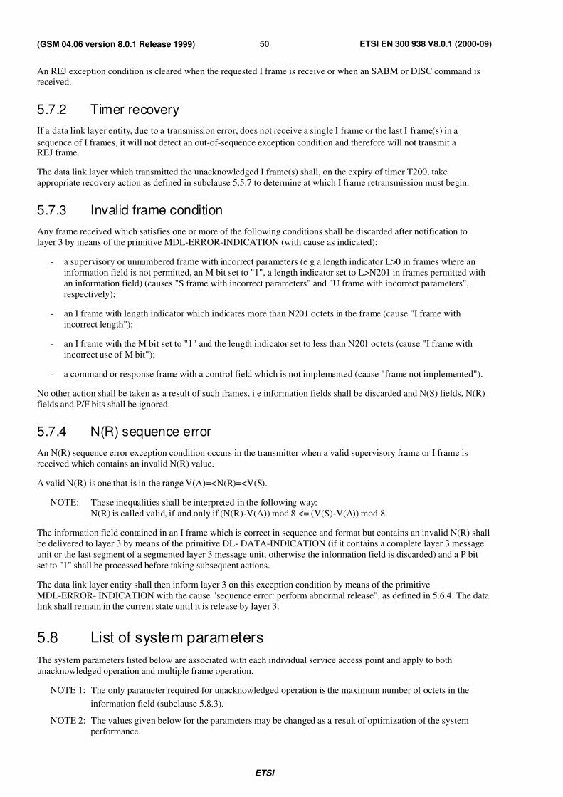
7/27/2019 MS & BTS Layer Specification
http://slidepdf.com/reader/full/ms-bts-layer-specification 50/59ETSI
ETSI EN 300 938 V8.0.1 (2000-09)50(GSM 04.06 version 8.0.1 Release 1999)
An REJ exception condition is cleared when the requested I frame is receive or when an SABM or DISC command is
received.
5.7.2 Timer recovery
If a data link layer entity, due to a transmission error, does not receive a single I frame or the last I frame(s) in a
sequence of I frames, it will not detect an out-of-sequence exception condition and therefore will not transmit aREJ frame.
The data link layer which transmitted the unacknowledged I frame(s) shall, on the expiry of timer T200, take
appropriate recovery action as defined in subclause 5.5.7 to determine at which I frame retransmission must begin.
5.7.3 Invalid frame condition
Any frame received which satisfies one or more of the following conditions shall be discarded after notification tolayer 3 by means of the primitive MDL-ERROR-INDICATION (with cause as indicated):
- a supervisory or unnumbered frame with incorrect parameters (e g a length indicator L>0 in frames where an
information field is not permitted, an M bit set to "1", a length indicator set to L>N201 in frames permitted with
an information field) (causes "S frame with incorrect parameters" and "U frame with incorrect parameters",
respectively);
- an I frame with length indicator which indicates more than N201 octets in the frame (cause "I frame with
incorrect length");
- an I frame with the M bit set to "1" and the length indicator set to less than N201 octets (cause "I frame with
incorrect use of M bit");
- a command or response frame with a control field which is not implemented (cause "frame not implemented").
No other action shall be taken as a result of such frames, i e information fields shall be discarded and N(S) fields, N(R)
fields and P/F bits shall be ignored.
5.7.4 N(R) sequence error
An N(R) sequence error exception condition occurs in the transmitter when a valid supervisory frame or I frame is
received which contains an invalid N(R) value.
A valid N(R) is one that is in the range V(A)=<N(R)=<V(S).
NOTE: These inequalities shall be interpreted in the following way:
N(R) is called valid, if and only if (N(R)-V(A)) mod 8 <= (V(S)-V(A)) mod 8.
The information field contained in an I frame which is correct in sequence and format but contains an invalid N(R) shallbe delivered to layer 3 by means of the primitive DL- DATA-INDICATION (if it contains a complete layer 3 message
unit or the last segment of a segmented layer 3 message unit; otherwise the information field is discarded) and a P bit
set to "1" shall be processed before taking subsequent actions.
The data link layer entity shall then inform layer 3 on this exception condition by means of the primitive
MDL-ERROR- INDICATION with the cause "sequence error: perform abnormal release", as defined in 5.6.4. The datalink shall remain in the current state until it is release by layer 3.
5.8 List of system parameters
The system parameters listed below are associated with each individual service access point and apply to both
unacknowledged operation and multiple frame operation.
NOTE 1: The only parameter required for unacknowledged operation is the maximum number of octets in the
information field (subclause 5.8.3).
NOTE 2: The values given below for the parameters may be changed as a result of optimization of the system
performance.
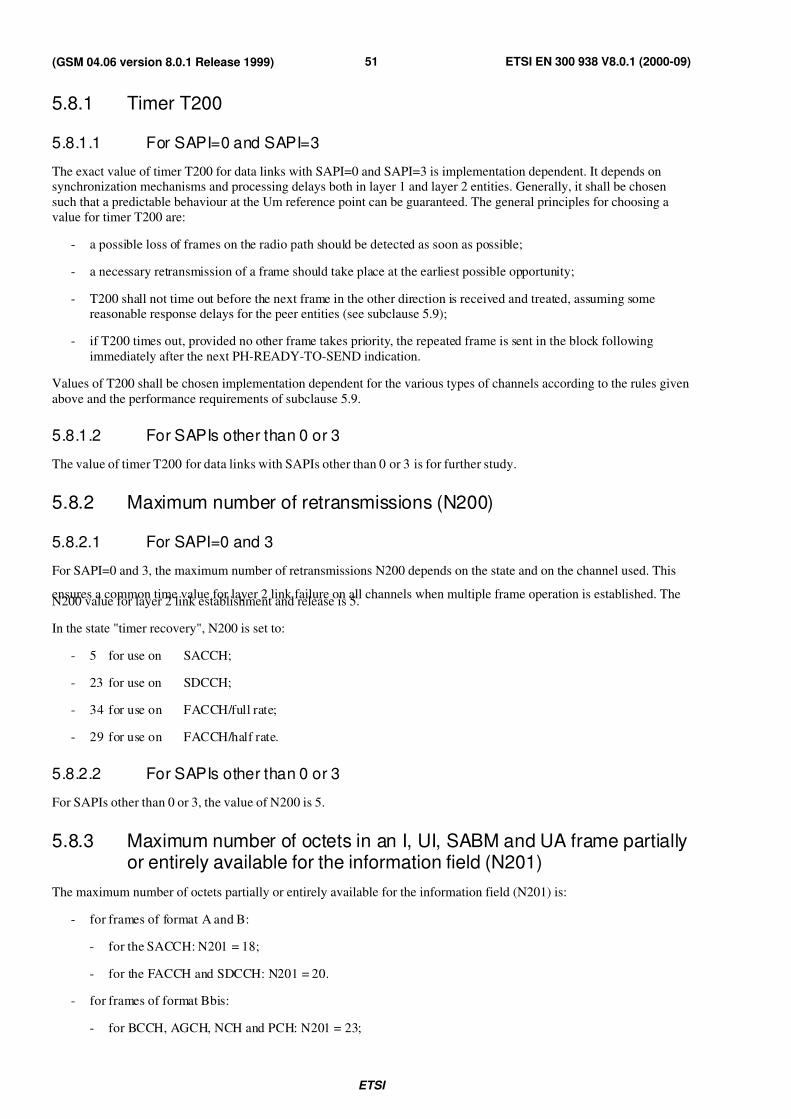
7/27/2019 MS & BTS Layer Specification
http://slidepdf.com/reader/full/ms-bts-layer-specification 51/59ETSI
ETSI EN 300 938 V8.0.1 (2000-09)51(GSM 04.06 version 8.0.1 Release 1999)
5.8.1 Timer T200
5.8.1.1 For SAPI=0 and SAPI=3
The exact value of timer T200 for data links with SAPI=0 and SAPI=3 is implementation dependent. It depends onsynchronization mechanisms and processing delays both in layer 1 and layer 2 entities. Generally, it shall be chosen
such that a predictable behaviour at the Um reference point can be guaranteed. The general principles for choosing a
value for timer T200 are:
- a possible loss of frames on the radio path should be detected as soon as possible;
- a necessary retransmission of a frame should take place at the earliest possible opportunity;
- T200 shall not time out before the next frame in the other direction is received and treated, assuming somereasonable response delays for the peer entities (see subclause 5.9);
- if T200 times out, provided no other frame takes priority, the repeated frame is sent in the block following
immediately after the next PH-READY-TO-SEND indication.
Values of T200 shall be chosen implementation dependent for the various types of channels according to the rules given
above and the performance requirements of subclause 5.9.
5.8.1.2 For SAPIs other than 0 or 3
The value of timer T200 for data links with SAPIs other than 0 or 3 is for further study.
5.8.2 Maximum number of retransmissions (N200)
5.8.2.1 For SAPI=0 and 3
For SAPI=0 and 3, the maximum number of retransmissions N200 depends on the state and on the channel used. This
ensures a common time value for layer 2 link failure on all channels when multiple frame operation is established. TheN200 value for layer 2 link establishment and release is 5.
In the state "timer recovery", N200 is set to:
- 5 for use on SACCH;
- 23 for use on SDCCH;
- 34 for use on FACCH/full rate;
- 29 for use on FACCH/half rate.
5.8.2.2 For SAPIs other than 0 or 3
For SAPIs other than 0 or 3, the value of N200 is 5.
5.8.3 Maximum number of octets in an I, UI, SABM and UA frame partiallyor entirely available for the information field (N201)
The maximum number of octets partially or entirely available for the information field (N201) is:
- for frames of format A and B:
- for the SACCH: N201 = 18;
- for the FACCH and SDCCH: N201 = 20.
- for frames of format Bbis:
- for BCCH, AGCH, NCH and PCH: N201 = 23;
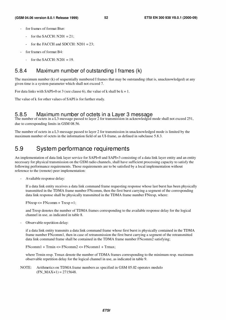
7/27/2019 MS & BTS Layer Specification
http://slidepdf.com/reader/full/ms-bts-layer-specification 52/59ETSI
ETSI EN 300 938 V8.0.1 (2000-09)52(GSM 04.06 version 8.0.1 Release 1999)
- for frames of format Bter:
- for the SACCH: N201 = 21;
- for the FACCH and SDCCH: N201 = 23;
- for frames of format B4:
- for the SACCH: N201 = 19.
5.8.4 Maximum number of outstanding I frames (k)
The maximum number (k) of sequentially numbered I frames that may be outstanding (that is, unacknowledged) at any
given time is a system parameter which shall not exceed 7.
For data links with SAPI=0 or 3 (see clause 6), the value of k shall be k = 1.
The value of k for other values of SAPI is for further study.
5.8.5 Maximum number of octets in a Layer 3 messageThe number of octets in a L3-message passed to layer 2 for transmission in acknowledged mode shall not exceed 251,
due to corresponding limits in GSM 08.56.
The number of octets in a L3-message passed to layer 2 for transmission in unacknowledged mode is limited by the
maximum number of octets in the information field of an UI-frame, as defined in subclause 5.8.3.
5.9 System performance requirements
An implementation of data link layer service for SAPI=0 and SAPI=3 consisting of a data link layer entity and an entity
necessary for physical transmission on the GSM radio channels, shall have sufficient processing capacity to satisfy the
following performance requirements. Those requirements are to be satisfied by a local implementation withoutreference to the (remote) peer implementation:
- Available response delay:
If a data link entity receives a data link command frame requesting response whose last burst has been physically
transmitted in the TDMA frame number FNcomm, then the first burst carrying a segment of the corresponding
data link response shall be physically transmitted in the TDMA frame number FNresp, where:
FNresp <= FNcomm + Tresp +1;
and Tresp denotes the number of TDMA frames corresponding to the available response delay for the logical
channel in use, as indicated in table 8.
- Observable repetition delay:
if a data link entity transmits a data link command frame whose first burst is physically contained in the TDMA
frame number FNcomm1, then in case of retransmission the first burst carrying a segment of the retransmitted
data link command frame shall be contained in the TDMA frame number FNcomm2 satisfying;
FNcomm1 + Trmin <= FNcomm2 <= FNcomm1 + Trmax;
where Trmin resp. Trmax denote the number of TDMA frames corresponding to the minimum resp. maximum
observable repetition delay for the logical channel in use, as indicated in table 9.
NOTE: Arithmetics on TDMA frame numbers as specified in GSM 05.02 operates modulo
(FN_MAX+1) = 2715648.

7/27/2019 MS & BTS Layer Specification
http://slidepdf.com/reader/full/ms-bts-layer-specification 53/59ETSI
ETSI EN 300 938 V8.0.1 (2000-09)53(GSM 04.06 version 8.0.1 Release 1999)
Table 8/GSM 04.06: Performance Parameters
SAPI Type of channel Available Minimum MaximumResponse Repetition RepetitionDelay Delay DelayTresp Trmin Trmax (3)
0 SDCCH MS: 11 51 51BSS: 32
0 FACCH/Full rate 9 26 39
0 FACCH/Half rate 10 34 44
3 SDCCH MS: 11 51 51 1)BSS: 32
3 SACCH (with TCH) 25/129 2) 312 416 2)
Values given in this table are measured in units of TDMA frame numbers, thus 1 unit corresponds to120/26 ms (approx. 4.615 ms).
NOTE 1: Only applicable if no SAPI 0 transmission is in progress. Otherwise no upper bound can be givendue to the priority of SAPI 0 transmission.
NOTE 2: This higher value is only applicable when the physical channel was not available for SAPI=3 dueto the transmission of a SAPI=0 frame.
NOTE 3: Only applicable if, when available for transmission, there is no supervisory frame with F=1 to
send (see for example subclause 5.5.2.1).
6 Special protocol operation on SAPI=0 and SAPI=3
This clause summarizes the specialities of the LAPDm protocol regarding the acknowledged mode operation on
SAPI=0 and SAPI=3.
The purpose is to adapt the multiple frame operation of LAPDm to the needs and the characteristics of the GSM system.
The adaptations and simplifications specified in this clause are mandatory for both entities, Mobile Station and Network
for SAPI=0 and SAPI=3.
As indicated in clause 5, the protocol operates on SAPI=0 in the following way:
- Data link establishment for SAPI=0 is always initiated by the Mobile Station.
- Data link establishment according to the contention resolution procedure (see subclause 5.4.1.4) is supported
when initiated by the MS on the main DCCH immediately after "immediate assignment" of that radio channel. In
other cases of link establishment contention resolution is not used.
- When changing the radio channel during assignment or handover procedures (layer 3 procedures), in
acknowledged mode on SAPI=0, the MS supports continuous transmission of layer 3 messages without loss by
offering the SUSPEND, RESUME and RECONNECT primitives, as specified in subclause 5.4.3. However,
duplication of at most one layer 3 data unit (in the MS to network direction) is possible.
For protocol operation on SAPI=0 as well as on SAPI=3 the following holds:
- For multiple frame operation, the window size k = 1 shall be used.
- The data link layer entity is not allowed to transmit an RNR frame and therefore shall never enter the
own-receiver busy state. The same applies to the peer-receiver-busy condition. This is applicable, because buffer
capacities necessary for avoiding such exception conditions are limited.
- When receiving, the data link layer entity may ignore RNR frames without notification.
- The procedure of enquiring the peer entity status by spontaneous transmission of a RR or REJ command frame,
as indicated in subclause 3.8.5, 3.8.6 and 3.8.7, need not be supported. However, reaction on receiving such
frames shall be as specified throughout the present document.
7/27/2019 MS & BTS Layer Specification
http://slidepdf.com/reader/full/ms-bts-layer-specification 54/59ETSI
ETSI EN 300 938 V8.0.1 (2000-09)54(GSM 04.06 version 8.0.1 Release 1999)
Annex A (normative):Random access procedures
A.1 Description of the procedure
A.1.1 Procedure in the MS
The random access procedure is initiated by layer 3. The data link layer will receive the 8 bit information content of the
random access burst in a DL-RANDOM ACCESS-REQUEST primitive. The primitive will also contain an indicationof the type of channel to be used. The data link layer will then pass the information field to the indicated physical layer
entity in a PH-RANDOM ACCESS-REQUEST primitive.
The physical layer will, upon sending the random access burst, send a PH-RANDOM ACCESS-CONFIRM primitive
containing the time slot in which the burst was sent. This information is passed then to layer 3 in a DL-RANDOM
ACCESS-CONFIRM primitive.
A.1.2 Procedure in the BS
The physical layer will provide the random access information field and an indication of the time slot in which the
random access burst was received to the data link layer in a PH-RANDOM ACCESS-INDICATION primitive. Theprimitive will also contain an indication of the type of channel on which the burst was received. The data link layer will
pass the information to layer 3 in a DL-RANDOM-ACCESS-INDICATION primitive.
A.2 Format
The format of the random access message at the data link layer consists of 8 bits. The order of bit transmission is
defined in GSM 04.04.
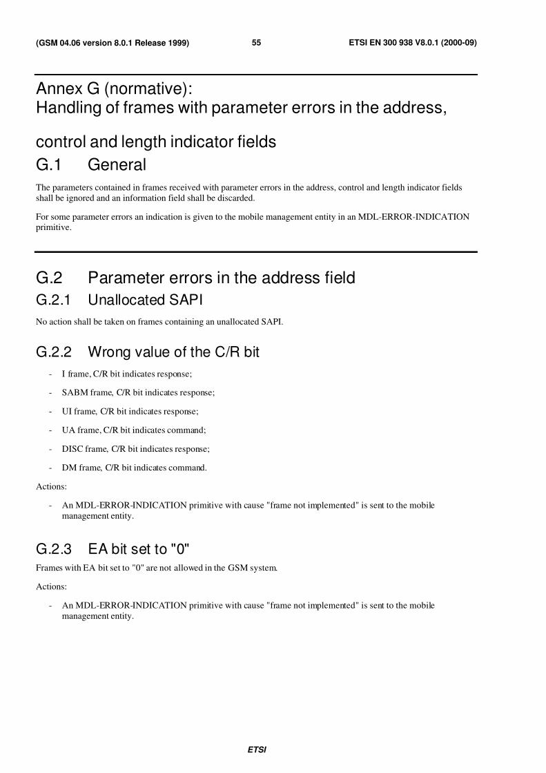
7/27/2019 MS & BTS Layer Specification
http://slidepdf.com/reader/full/ms-bts-layer-specification 55/59ETSI
ETSI EN 300 938 V8.0.1 (2000-09)55(GSM 04.06 version 8.0.1 Release 1999)
Annex G (normative):Handling of frames with parameter errors in the address,
control and length indicator fields
G.1 General
The parameters contained in frames received with parameter errors in the address, control and length indicator fields
shall be ignored and an information field shall be discarded.
For some parameter errors an indication is given to the mobile management entity in an MDL-ERROR-INDICATIONprimitive.
G.2 Parameter errors in the address field
G.2.1 Unallocated SAPI
No action shall be taken on frames containing an unallocated SAPI.
G.2.2 Wrong value of the C/R bit
- I frame, C/R bit indicates response;
- SABM frame, C/R bit indicates response;
- UI frame, C/R bit indicates response;
- UA frame, C/R bit indicates command;
- DISC frame, C/R bit indicates response;
- DM frame, C/R bit indicates command.
Actions:
- An MDL-ERROR-INDICATION primitive with cause "frame not implemented" is sent to the mobile
management entity.
G.2.3 EA bit set to "0"Frames with EA bit set to "0" are not allowed in the GSM system.
Actions:
- An MDL-ERROR-INDICATION primitive with cause "frame not implemented" is sent to the mobile
management entity.
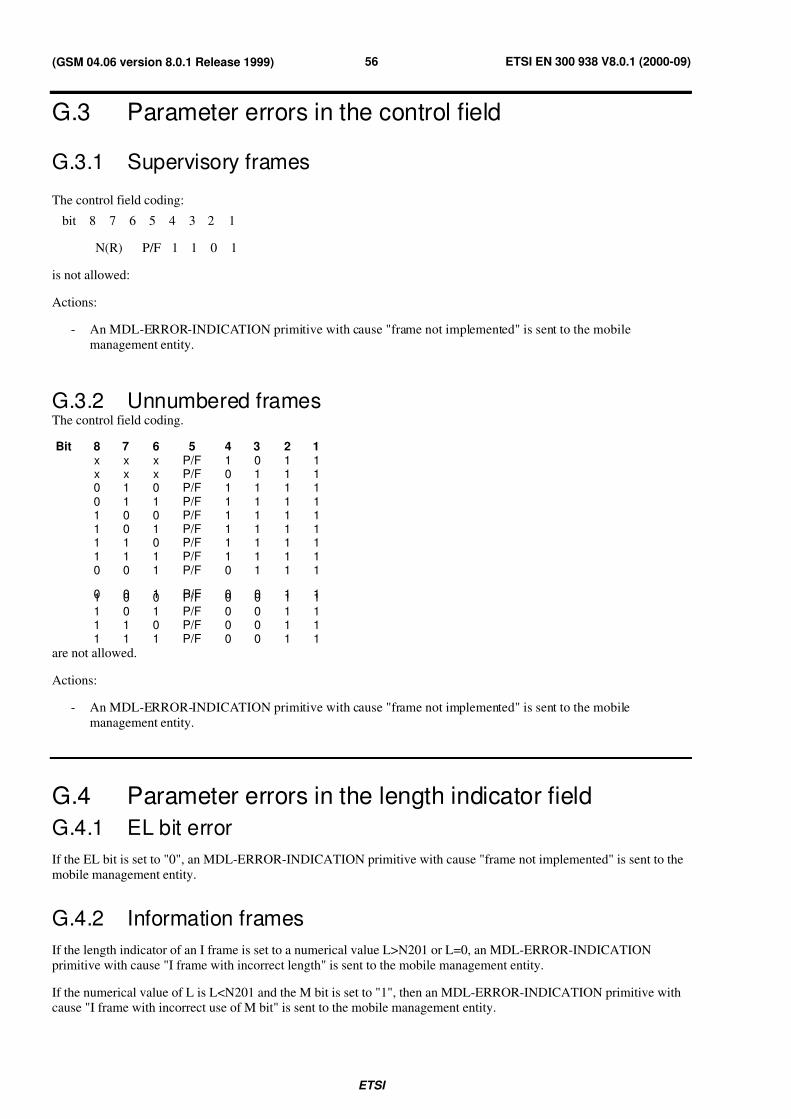
7/27/2019 MS & BTS Layer Specification
http://slidepdf.com/reader/full/ms-bts-layer-specification 56/59ETSI
ETSI EN 300 938 V8.0.1 (2000-09)56(GSM 04.06 version 8.0.1 Release 1999)
G.3 Parameter errors in the control field
G.3.1 Supervisory frames
The control field coding:
bit 8 7 6 5 4 3 2 1
N(R) P/F 1 1 0 1
is not allowed:
Actions:
- An MDL-ERROR-INDICATION primitive with cause "frame not implemented" is sent to the mobile
management entity.
G.3.2 Unnumbered framesThe control field coding.
Bit 8 7 6 5 4 3 2 1x x x P/F 1 0 1 1x x x P/F 0 1 1 10 1 0 P/F 1 1 1 10 1 1 P/F 1 1 1 11 0 0 P/F 1 1 1 11 0 1 P/F 1 1 1 11 1 0 P/F 1 1 1 11 1 1 P/F 1 1 1 10 0 1 P/F 0 1 1 1
0 0 1 P/F 0 0 1 11 0 0 P/F 0 0 1 11 0 1 P/F 0 0 1 11 1 0 P/F 0 0 1 11 1 1 P/F 0 0 1 1
are not allowed.
Actions:
- An MDL-ERROR-INDICATION primitive with cause "frame not implemented" is sent to the mobile
management entity.
G.4 Parameter errors in the length indicator field
G.4.1 EL bit error
If the EL bit is set to "0", an MDL-ERROR-INDICATION primitive with cause "frame not implemented" is sent to the
mobile management entity.
G.4.2 Information frames
If the length indicator of an I frame is set to a numerical value L>N201 or L=0, an MDL-ERROR-INDICATION
primitive with cause "I frame with incorrect length" is sent to the mobile management entity.
If the numerical value of L is L<N201 and the M bit is set to "1", then an MDL-ERROR-INDICATION primitive withcause "I frame with incorrect use of M bit" is sent to the mobile management entity.
7/27/2019 MS & BTS Layer Specification
http://slidepdf.com/reader/full/ms-bts-layer-specification 57/59ETSI
ETSI EN 300 938 V8.0.1 (2000-09)57(GSM 04.06 version 8.0.1 Release 1999)
G.4.3 Supervisory frames
If a supervisory frame is received with L>0 or with the M bit set to "1", an MDL-ERROR-INDICATION primitive with
cause "S frame with incorrect parameters" is sent to the mobile management entity.
G.4.4 DISC and DM framesIf a DISC or DM frame is received with L>0 or with the M bit set to "1", an MDL-ERROR-INDICATION primitive
with cause "U frame with incorrect parameters" is sent to the mobile management entity.
G.4.5 SABM UA and UI frames
If SABM, UA or UI frames are received with L>N201 or with the M bit set to "1" an MDL-ERROR-INDICATION
primitive with cause "U frame with incorrect parameters" is sent to the mobile management entity.
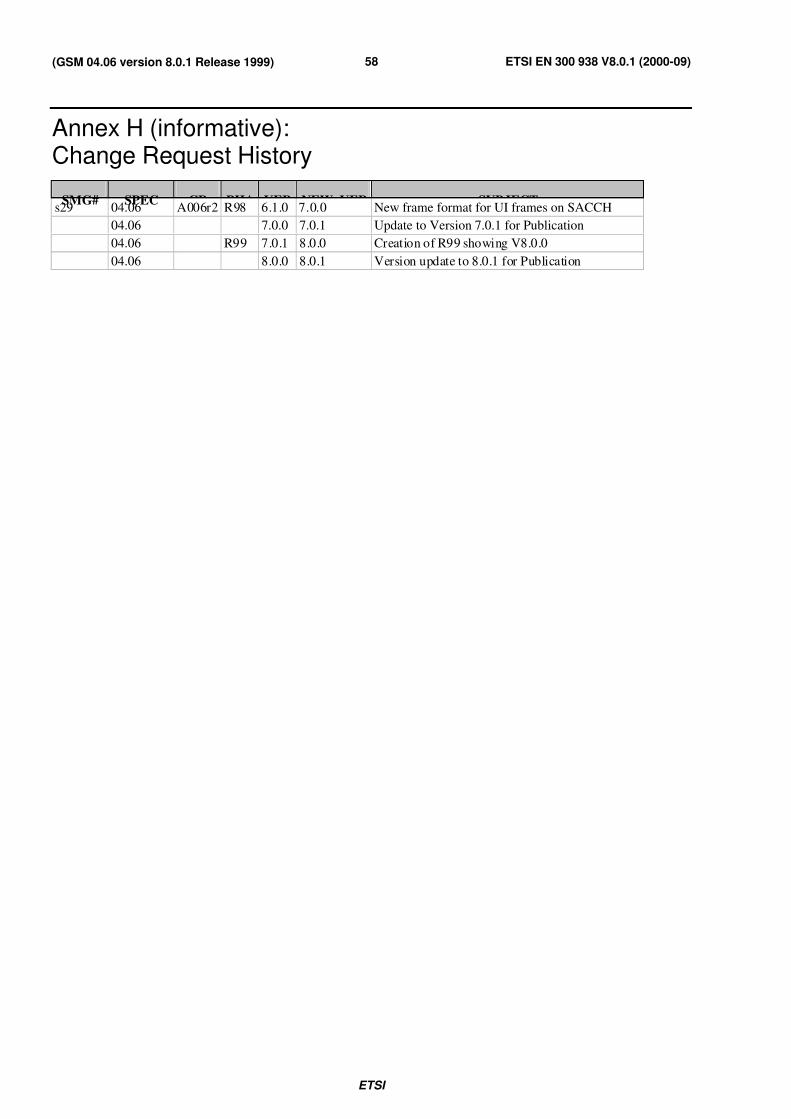
7/27/2019 MS & BTS Layer Specification
http://slidepdf.com/reader/full/ms-bts-layer-specification 58/59ETSI
ETSI EN 300 938 V8.0.1 (2000-09)58(GSM 04.06 version 8.0.1 Release 1999)
Annex H (informative):Change Request History
SMG# SPEC CR PHA VER NEW_VER SUBJECTs29 04.06 A006r2 R98 6.1.0 7.0.0 New frame format for UI frames on SACCH
04.06 7.0.0 7.0.1 Update to Version 7.0.1 for Publication
04.06 R99 7.0.1 8.0.0 Creation of R99 showing V8.0.0
04.06 8.0.0 8.0.1 Version update to 8.0.1 for Publication
7/27/2019 MS & BTS Layer Specification
http://slidepdf.com/reader/full/ms-bts-layer-specification 59/59
ETSI EN 300 938 V8.0.1 (2000-09)59(GSM 04.06 version 8.0.1 Release 1999)
History
Document history
V8.0.0 April 2000 One-step Approval Procedure OAP 20000825: 2000-04-26 to 2000-08-25
V8.0.1 September 2000 Publication