mri3-le – digital multifunctional relay for earth fault ... · the mrl3-le digital...
TRANSCRIPT
MRI3-LE – Digital multifunctional relay
for earth fault protection
(January 2010) Manual MRI3-LE (Revision New)

Woodward Manual MRI3-LE EN
2 TD_MRI3-LE_01_10_EN_Rev.New
Woodward Governor Company reserves the right to update any portion of this publication at any time. Information provided by Woodward Governor Company is believed to be correct and reliable. However, no responsibility is as-
sumed by Woodward Governor Company unless otherwise expressly undertaken.
© Woodward 1994-2008

Manual MRI3-LE EN Woodward
TD_MRI3-LE_01_10_EN_Rev.New 3
Contents
1. Introduction and application ........................................................................ 5
2. Features and characteristics ........................................................................ 6
3. Design ............................................................................................................. 7 3.1 Connections ..................................................................................................................... 7
3.1.1 Analog input circuits ..................................................................................................... 7 3.1.2 Output relays ................................................................................................................ 7
3.2 Relay output contacts ....................................................................................................... 8 3.2.1 Fault recorder ............................................................................................................... 9
3.3 LEDs .............................................................................................................................. 11
4. Working principle ........................................................................................ 12 4.1 Analog circuits ................................................................................................................ 12 4.2 Digital circuits ................................................................................................................. 12 4.3 Earth fault protection ...................................................................................................... 13
4.3.1 Generator stator earth fault protection ........................................................................ 13 4.3.2 System earth fault protection ...................................................................................... 13
4.4 Demand imposed on the main current transformers ...................................................... 14
5. Operation and settings ............................................................................... 15 5.1 Display ........................................................................................................................... 15 5.2 Setting procedure ........................................................................................................... 16 5.3 System parameter .......................................................................................................... 16
5.3.1 Display of measuring values as primary quantities (Iprim earth) ................................... 16 5.3.2 Nominal frequency ..................................................................................................... 16 5.3.3 Display of the activation storage (FLSH/NOFL) .......................................................... 16 5.3.4 Parameter switch/ for parameter set change .............................................................. 16
5.4 Parameter protection ...................................................................................................... 17 5.4.1 Pickup current for earth phase overcurrent element (IE>) ........................................... 17 5.4.2 Time current characteristics for earth overcurrent element (CHAR IE) ....................... 17 5.4.3 Trip delay or time factor for earth overcurrent element (tIE>) ...................................... 17 5.4.4 Reset setting for all tripping characteristics in the earth current path .......................... 17 5.4.5 Current setting for high set element of earth fault supervision (IE>>) .......................... 18 5.4.6 Trip delay for high set element of earth fault supervision (tIE>>) ................................. 18 5.4.7 Circuit breaker failure protection tCBFP ..................................................................... 18 5.4.8 Adjustment of the slave address ................................................................................ 18 5.4.9 Setting of Baud-rate ................................................................................................... 18 5.4.10 Setting of parity ...................................................................................................... 18
5.5 Fault recorder ................................................................................................................. 19 5.5.1 Adjustment of the fault recorder ................................................................................. 19 5.5.2 Number of the fault recordings ................................................................................... 19 5.5.3 Adjustment of trigger occurrences .............................................................................. 19 5.5.4 Pre-trigger time (Tpre) ................................................................................................ 19
5.6 Adjustment of the clock .................................................................................................. 19 5.7 Additional function .......................................................................................................... 20 5.8 Indication of measuring and fault values ........................................................................ 21
5.8.1 Indication of measuring values ................................................................................... 21 5.8.2 Units of the measuring values displayed ................................................................... 21 5.8.3 Indication of fault data ................................................................................................ 22 5.8.4 Fault memory ............................................................................................................. 22
5.9 Reset ............................................................................................................................. 23 5.9.1 Erasure of fault storage .............................................................................................. 23
6. Relay testing and commissioning ............................................................. 24 6.1 Power-On ....................................................................................................................... 24 6.2 Testing the output relays and LEDs ............................................................................... 24 6.3 Checking the set values ................................................................................................. 24 6.4 Secondary injection test ................................................................................................. 25
6.4.1 Test equipment .......................................................................................................... 25 6.4.2 Example of test circuit for MRI3-LE relays .................................................................. 25
Woodward Manual MRI3-LE EN
4 TD_MRI3-LE_01_10_EN_Rev.New
6.4.3 Checking the input circuit and measured values ........................................................ 25 6.4.4 Checking the operating and resetting values of the relay ........................................... 25 6.4.5 Checking the relay operating time .............................................................................. 26 6.4.6 Checking the high set element of the relay ................................................................. 26
6.5 Primary injection test ...................................................................................................... 26 6.6 Maintenance................................................................................................................... 26
7. Technical data .............................................................................................. 27 7.1 Measuring input circuit ................................................................................................... 27 7.2 Common data ................................................................................................................. 27 7.3 Setting ranges and steps ................................................................................................ 28
7.3.1 Earth fault protection .................................................................................................. 28 7.3.2 CBFP Circuit breaker failure protection protection ...................................................... 28 7.3.3 Interface parameter .................................................................................................... 28 7.3.4 Parameter for the fault recorder ................................................................................. 28 7.3.5 Inverse time overcurrent protection relay ................................................................... 29
7.4 Inverse time characteristics ............................................................................................ 30 7.5 Output contacts .............................................................................................................. 33
8. Order form .................................................................................................... 34
Manual MRI3-LE EN Woodward
TD_MRI3-LE_01_10_EN_Rev.New 5
1. Introduction and application The MRl3-LE digital multifunctional relay is a universal earth fault protection device intended for use in low voltage and medium-voltage systems Independent (Definite) time earth overcurrent and earth short circuit relay, two-element (low and high set) with definite or inverse time characteristics, Important: For additional common data of all MR-relays please refer to manual "MR - Digital Multifunctional relays". On the last page of this manual you can find the valid software versions.
Woodward Manual MRI3-LE EN
6 TD_MRI3-LE_01_10_EN_Rev.New
2. Features and characteristics Digital filtering of the measured values by using discrete Fourier analysis to suppress the high frequence harmonics and DC components induced by faults or system operations, two parameter sets, selectable protective functions between:
- definite time earth overcurrent relay and - inverse time earth overcurrent relay,
selectable inverse time characteristics according to IEC 255-4: - Normal Inverse (Type A) - Very Inverse (Type B) - Extremely Inverse (Type C) - Special characteristics,
reset setting for inverse time characteristics selectable, numerical display of setting values, actual measured values, memorized fault data, etc., display of measuring values as primary quantities, withdrawable modules with automatic short circuiter of C.T. inputs when modules are withdrawn, circuit breaker failure protection, storage of trip values and switching-off time (tCBFP) of 5 fault occurences (fail-safe of voltage), recording of up to eight fault occurences with time stamp, free assignment of output relays serial data exchange via RS485 or RS232 interface possible; with Modbus Protocol, suppression of indication after an activation (LED flash), display of date and time

Manual MRI3-LE EN Woodward
TD_MRI3-LE_01_10_EN_Rev.New 7
3. Design
3.1 Connections Earth current measuring:
Figure 3.1: Earth-fault measuring by means of ring-core C.T. (IE)
3.1.1 Analog input circuits The protection unit receives the analog input signal of the eath current IE (B1-B2 The constantly detected current measuring values are galvanically decoupled, filtered and finally fed to the analog/digital converter.
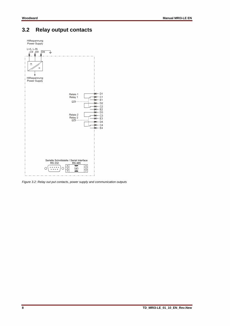
3.1.2 Output relays The MRI3-LE is equipped with 2 output relays. All protective functions can be optionally assigned: • Relay 1: C1, D1, E1 and C2, D2, E2 • Relay 2: C3, D3, E3 and C4, D4, E4 All trip and alarm relays are working current relays.
Woodward Manual MRI3-LE EN
8 TD_MRI3-LE_01_10_EN_Rev.New
3.2 Relay output contacts
Figure 3.2: Relay out put contacts, power supply and communication outputs

Manual MRI3-LE EN Woodward
TD_MRI3-LE_01_10_EN_Rev.New 9
3.2.1 Fault recorder The MRI3-LE is equipped with a disturbance value recorder which records the measured analogue values as momentary values. The momentary value iE, is scanned within a grid 1.25 ms (with 50 Hz) or 1.041 ms (with 60 Hz) and filed in a circulating storage. The max. storage capacity amounts to 16 s (with 50 Hz) or 13.33 s (with 60 Hz). Storage division Independent of the recording time, the entire storage capacity can be divided into several cases of disturbance with a shorter recording time each. In addition, the deletion behaviour of the fault re-corder can be influenced. No writing over If 2, 4 or 8 recordings are chosen, the complete memory is divided into the relevant number of par-tial segments. If this max. number of fault event has been exceeded, the fault recorder block any further recordings in order to prevent that the stored data are written over. After the data have been read and deleted, the recorder to ready again for further action. Writing over If 1, 3 or 7 recordings are chosen, the relevant number of partial segments is reserved in the com-plete memory. If the memory is full, a new recording will always write over the oldest one. The memory part of the fault recorder is designed as circulating storage. In this example 7 fault records can be stored (written over). Memory space 6 to 4 is occupied. Memory space 5 is currently being written in
Figure 3.5: Division of the memory into 8 segments, for example
Since memory spaces 6, 7 and 8 are occupied, this example shows that the memory has been as-signed more than eight recordings. This means that No. 6 is the oldest fault recording and No. 4 the most recent one.
Woodward Manual MRI3-LE EN
10 TD_MRI3-LE_01_10_EN_Rev.New
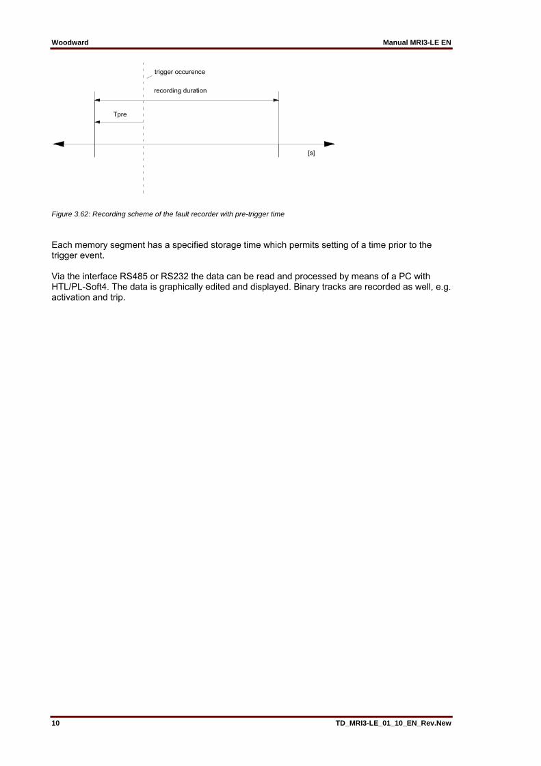
Figure 3.62: Recording scheme of the fault recorder with pre-trigger time
Each memory segment has a specified storage time which permits setting of a time prior to the trigger event. Via the interface RS485 or RS232 the data can be read and processed by means of a PC with HTL/PL-Soft4. The data is graphically edited and displayed. Binary tracks are recorded as well, e.g. activation and trip.
trigger occurence
recording duration
Tpre
[s]
Manual MRI3-LE EN Woodward
TD_MRI3-LE_01_10_EN_Rev.New 11
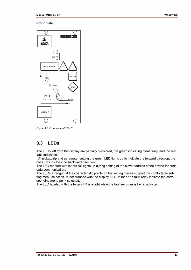
Front plate
Figure 3.3: Front plate MRI3-LE
3.3 LEDs The LEDs left from the display are partially bi-colored, the green indicating measuring, and the red fault indication. . At pickup/trip and parameter setting the green LED lights up to indicate the forward direction, the red LED indicates the backward direction. The LED marked with letters RS lights up during setting of the slave address of the device for serial data communication. The LEDs arranged at the characteristic points on the setting curves support the comfortable set-ting menu selection. In accordance with the display 5 LEDs for earth-fault relay indicate the corre-sponding menu point selected. The LED labeled with the letters FR is a light while the fault recorder is being adjusted.

Woodward Manual MRI3-LE EN
12 TD_MRI3-LE_01_10_EN_Rev.New
4. Working principle
4.1 Analog circuits The incoming currents from the main current transformers on the protected object are converted to voltage signals in proportion to the currents via the input transformer and burden. The noise signals caused by inductive and capacitive coupling are suppressed by an analog R-C filter circuit. The analog voltage signals are fed to the A/D-converter of the microprocessor and transformed to digital signals through Sample- and Hold-circuits. The analog signals are sampled at 50 Hz (60 Hz) with a sampling frequency of 800 Hz (960 Hz), namely, a sampling rate of 1.25 ms (1.04 ms) for every measuring quantity. (16 scans per period).
4.2 Digital circuits The essential part of the MRI3-LE relay is a powerful microcontroller. All of the operations, from the analog digital conversion to the relay trip decision, are carried out by the microcontroller digitally. The relay program is located in an EPROM (Electrically-Programmable-Read-Only-Memory). With this program the CPU of the microcontroller calculates the three phase currents and ground current in order to detect a possible fault situation in the protected object. For the calculation of the current value an efficient digital filter based on the Fourier Transformation (DFFT - Discrete Fast Fourier Transformation) is applied to sup-press high frequency harmonics and DC components caused by fault-induced transients or other system disturbances. The calculated actual current values are compared with the relay settings. If a phase current ex-ceeds the pickup value, an alarm is given and after the set trip delay has elapsed, the correspond-ing trip relay is activated. The relay setting values for all parameters are stored in a parameter memory (EEPROM - Electri-cally Erasable Programmable Read-only Memory), so that the actual relay settings cannot be lost, even if the power supply is interrupted. The microprocessor is supervised by a built-in "watch-dog" timer. In case of a failure the watchdog timer re-sets the microprocessor and gives an alarm signal, via the output relay "self supervision".

Manual MRI3-LE EN Woodward
TD_MRI3-LE_01_10_EN_Rev.New 13
4.3 Earth fault protection
4.3.1 Generator stator earth fault protection With the generator neutral point earthed as shown in Figure 4.1 the MRI3-LE picks up only to phase earth faults between the generator and the location of the current transformers supplying the relay. Earth faults beyond the current transformers, i.e. on the consumer or line side, will not be detected.
Figure 4.1: Generator stator earth fault protection
4.3.2 System earth fault protection With the generator neutral point earthed as shown in Figure 4.2, the MRI3-LE picks up only to earth faults in the power system connected to the generator. It does not pick up to earth faults on the generator terminals or in generator stator.
Figure 4.2: System earth fault protection

Woodward Manual MRI3-LE EN
14 TD_MRI3-LE_01_10_EN_Rev.New
4.4 Demand imposed on the main current transformers The current transformers have to be rated in such a way, that a saturation should not occur within the following operating current ranges: Independent time overcurrent function: K1 = 2 Inverse time overcurrent function: K1 = 20 High-set function: K1 = 1.2 - 1.5 K1 = Current factor related to set value Moreover, the current transformers have to be rated according to the maximum expected short cir-cuit current in the network or in the protected objects. The low power consumption in the current circuit of MRI3, namely <0.2 VA, has a positive effect on the selection of current transformers. It implies that, if an electromechanical relay is replaced by MRI3, a high accuracy limit factor is automatically obtained by using the same current transformer.
Manual MRI3-LE EN Woodward
TD_MRI3-LE_01_10_EN_Rev.New 15
5. Operation and settings
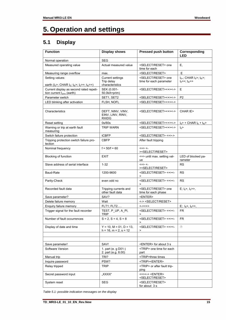
5.1 Display
Function Display shows Pressed push button Corresponding LED
Normal operation SEG
Measured operating value Actual measured value <SELECT/RESET> one time for each
E,
Measuring range overflow max. <SELECT/RESET> E
Setting values: earth (IE>; CHAR IE; tIE>; IE>>; tIE>>)
Current settings Trip delay characteristics
<SELECT/RESET> one time for each parameter
IE>; CHAR IE>; tIE>; IE>>; tIE>>
Current display as second rated repeti-tion current Iprim (earth)
SEK (0.001-50.0kA=prim)
<SELECT/RESET><+><-> E
Parameter switch SET1, SET2 <SELECT/RESET><+><-> P2
LED blinking after activation FLSH, NOFL <SELECT/RESET><+><->
Characteristics DEFT, NINV, VINV, EINV, LINV, RINV, RXIDG
<SELECT/RESET><+><-> CHAR IE>
Reset setting 0s/60s <SELECT/RESET><+><-> IE> + CHAR IE + tIE>
Warning or trip at earth fault measuring
TRIP WARN <SELECT/RESET><+><-> IE>
Switch failure protection tCBFP <SELECT/RESET> <+>->
Tripping protection switch failure pro-tection
CBFP After fault tripping
Nominal frequency f = 50/f = 60 <+> <-><SELECT/RESET>
Blocking of function EXIT <+> until max. setting val-ue
LED of blocked pa-rameter
Slave address of serial interface 1-32 <+> <-><SELECT/RESET>
RS
Baud-Rate 1200-9600 <SELECT/RESET> <+><->
RS
Parity-Check even odd no <SELECT/RESET> <+><->
RS
Recorded fault data Tripping currents and other fault data
<SELECT/RESET> one time for each phase
E; IE>, IE>>,
Save parameter? SAV? <ENTER>
Delete failure memory Wait <-> <SELECT/RESET>
Enquiry failure memory FLT1; FLT2..... <-><+> E; IE>, IE>>,
Trigger signal for the fault recorder TEST, P_UP, A_PI, TRIP
<SELECT/RESET> <+><->
FR
Number of fault occurrences S = 2, S = 4, S = 8 <SELECT/RESET> <+><->
FR
Display of date and time Y = 10, M = 01, D = 13, h = 16, m = 2, s = 12
<SELECT/RESET> <+><->
Save parameter! SAV! <ENTER> for about 3 s
Software Version 1. part (e. g D01-) 2. part (e.g. 8.00)
<TRIP> one time for each part
Manual trip TRI? <TRIP>three times
Inquire password PSW? <TRIP><ENTER>
Relay tripped TRIP <TRIP> or after fault trip-ping
Secret password input „XXXX“ <+><-> <ENTER> <SELECT/RESET>
System reset SEG <SELECT/RESET> for about 3 s
Table 5.1: possible indication messages on the display
Woodward Manual MRI3-LE EN
16 TD_MRI3-LE_01_10_EN_Rev.New
1) refer to 4.3
5.2 Setting procedure After push button <SELECT/RESET> has been pressed, always the next measuring value is indi-cated. Firstly the operating measuring values are indicated and then the setting parameters. By pressing the <ENTER> push button the setting values can directly be called up and changed. Be-fore parameter setting can be started the relevant password must be entered (refer to chapter 4.3 of the "MR Digital Multifunctional Relay" description).
5.3 System parameter
5.3.1 Display of measuring values as primary quantities (Iprim earth) With this parameter it is possible to show the indication as primary measuring value. For this pur-pose the parameter must be set to be equal with the rated primary CT current. If the parameter is set to "SEK", the measuring value is shown as a multiple of the rated secondary CT current. Example: The current transformer used is of 1500/5 A. The flowing current is 1380 A. The parameter is set to 1500 A and on the display "1380 A" are shown. If the parameter is set to "SEK", the value shown on the display is "0.92" x In. Note: The pick-up value is set to a multiple of the rated secondary CT current.
5.3.2 Nominal frequency The adapted FFT-algorithm requires the nominal frequency as a parameter for correct digital sam-pling and filtering of the input currents. By pressing <SELECT> the display shows "f=50" or "f=60". The desired nominal frequency can be adjusted by <+> or <-> and then stored with <ENTER>.
5.3.3 Display of the activation storage (FLSH/NOFL) If after an activation the existing current drops again below the pickup value, e.g. I>, without a trip has been initiated, LED I> signals that an activation has occurred by flashing fast. The LED keeps flashing until it is reset again (push button <RESET>). Flashing can be suppressed when the pa-rameter is set to NOFL.
5.3.4 Parameter switch/ for parameter set change By means of the parameter-change-over switches it is possible to activate two different parameter sets. Switching over of the parameter sets can either be done by means of software or via this pa-rameter.

Manual MRI3-LE EN Woodward
TD_MRI3-LE_01_10_EN_Rev.New 17
5.4 Parameter protection
5.4.1 Pickup current for earth phase overcurrent element (IE>) The setting value for this parameter that appears on the display is related to the nominal earth cur-rent (IEN) of the relay. This means: pickup current (Is) = displayed value x nominal current (IEN) e.g. displayed value = 1.25 then, Is = 1.25 x IN.
5.4.2 Time current characteristics for earth overcurrent element (CHAR IE) By setting this parameter, one of the following 6 messages appears on the display: DEFT - Definite Time NINV - Normal Inverse VINV - Very Inverse EINV - Extremely Inverse RINV - RI-Inverse LINV - Long Time Inverse RXID Special characteristic Anyone of these four characteristics can be changed by using <+> <->-push buttons, and can be stored by using <ENTER>-push button.
5.4.3 Trip delay or time factor for earth overcurrent element (tIE>) Usually, after the characteristic is changed, the time delay or the time multiplier should be changed accordingly. In order to avoid an unsuitable arrangement of relay modes due to carelessness of the operator, the following precautions are taken: If, through a new setting, another relay characteristic other than the old one has been chosen (e.g. from DEFT to NINV), but the time delay setting has not been changed despite the warning from the flashing LED, the relay will be set to the most sensitive time setting value of the selected character-istics after five minutes warning of flashing LED tIE>. The most sensitive time setting value means the fastest tripping for the selected relay characteristic. If a definite time characteristic has been se-lected, the display shows the trip delay in seconds. When selecting an inverse time characteristic, the time multiplier appears on the display. Both settings can be charges by push-buttons <+><->. When the time delay or the time multiplier is set out of range (Text "EXIT" appears on the display), the low set element of the earth overcurrent relay is blocked. The "WARN"-relay will not be blocked.
5.4.4 Reset setting for all tripping characteristics in the earth current path To ensure tripping, even with recurring fault pulses shorter than the set trip delay, the reset mode for inverse time tripping characteristics can be switched over. If the adjustment tRST is set at 60 s, the tripping time is only reset after 60 s faultless condition. This function is not available if tRST is set to 0. With fault current cease the trip delay is reset immediately and started again at recurring fault current.
Woodward Manual MRI3-LE EN
18 TD_MRI3-LE_01_10_EN_Rev.New
5.4.5 Current setting for high set element of earth fault supervision (IE>>) The current setting value of this parameter appearing on the display is related to the rated current of the relay. This means: IE>> = displayed value x IN. When the current setting for high set element is set out of range (on display appears "EXIT"), the high set element of the earth overcurrent relay is blocked.
5.4.6 Trip delay for high set element of earth fault supervision (tIE>>) Independent from the chosen tripping characteristic for IE>, the high set element IE>> has always a definite-time tripping characteristic. An indication value in seconds appears on the display.
5.4.7 Circuit breaker failure protection tCBFP The CB failure protection is based on supervision of phase currents during tripping events. Only af-ter tripping this protective function becomes active. The test criterion is whether all phase currents are dropped to <1% x IN within tCBFP (Circuit Breaker Failure Protection - adjustable between 0.1 - 2.0 s). If not all of the phase currents have dropped to <1%xIN within this time, CB failure is detect-ed and the related relay activated. The CB failure protection function is deactivated again as soon as the phase currents have dropped to <1% x IN within tCBFP
5.4.8 Adjustment of the slave address Pressing push buttons <+> and <-> the slave address can be set in the range of 1-32.
5.4.9 Setting of Baud-rate Different transmission rates (Baud rate) can be set for data transmission via Modbus protocol. The rate can be changed by push buttons <+> and <-> and saved by pressing <ENTER>.
5.4.10 Setting of parity The following three parity settings are possible: • "even" = even • "odd" = odd • "no" = no parity check The setting can be changed by push buttons <+> and <-> and saved by pressing <ENTER>.
Manual MRI3-LE EN Woodward
TD_MRI3-LE_01_10_EN_Rev.New 19
5.5 Fault recorder
5.5.1 Adjustment of the fault recorder The MRI3-LE is equipped with a fault recorder (see chapter3.2.1). Three parameters can be de-termined.
5.5.2 Number of the fault recordings The max. recording time is 16 s at 50 Hz or 13.33 s at 60 Hz. The number of max. recordings requested has to be determined in advance. There is a choice of (1)* 2, (3)* 4 or (7)* 8 recordings and dependent on this the duration of the individual fault record-ings is defined, i.e. (1)* 2 recordings for a duration of 8 s (with 50 Hz) (6.66 s with 60 Hz) (3)* 4 recordings for a duration of 4 s (with 50 Hz) (3.33 s with 60 Hz) (7)* 8 recordings for a duration of 2 s (with 50 Hz) (1.66 s with 60 Hz) * is written over at new trigger signal
5.5.3 Adjustment of trigger occurrences There is a choice between four different occurrences: P_UP (PickUP) Storage is initiated after recognition of a general activation TRIP Storage is initiated after a trip has occurred A_PI (After Pickup) Storage is initiated after the last activation threshold was fallen short of. TEST Storing is activated by simultaneous actuation of the keys <+> and <->. During the recording time the display shows “Test”.
5.5.4 Pre-trigger time (Tpre) By the time Tpre it is determined which period of time prior to the trigger occurrence should be stored as well. It is possible to adjust a time between 0.05s and 8s. With keys <+> and <-> the val-ues can be changed and with <ENTER> be saved.
5.6 Adjustment of the clock When adjusting the date and time, LED lights up. The adjustment method is as follows: Date: Year Y=00 Month M=00 Day D=00 Time: Hour h=00 Minute m=00 Second s=00 The clock starts with the set date and time as soon as the supply voltage is switched on. The time is safe-guarded against short-term voltage failures (min. 6 minutes). Note: The window for parameter setting of the clock is located behind the measured value display. The parameter window can be accessed via the <SELECT/RESET> key.
Woodward Manual MRI3-LE EN
20 TD_MRI3-LE_01_10_EN_Rev.New
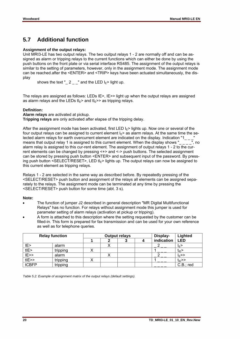
5.7 Additional function Assignment of the output relays: Unit MRI3-LE has two output relays. The two ouitput relays 1 - 2 are normally off and can be as-signed as alarm or tripping relays to the current functions which can either be done by using the push buttons on the front plate or via serial interface RS485. The assignment of the output relays is similar to the setting of parameters, however, only in the assignment mode. The assignment mode can be reached.after the <ENTER> and <TRIP> keys have been actuated simultaneously, the dis-play shows the text "_ 2 _ _" and the LED IE> light up. The relays are assigned as follows: LEDs IE>, IE>> light up when the output relays are assigned as alarm relays and the LEDs tIE> and tIE>> as tripping relays. Definition: Alarm relays are activated at pickup. Tripping relays are only activated after elapse of the tripping delay. After the assignment mode has been activated, first LED IE> lights up. Now one or several of the four output relays can be assigned to current element IE> as alarm relays. At the same time the se-lected alarm relays for earth overcurrent element are indicated on the display. Indication "1_ _ _" means that output relay 1 is assigned to this current element. When the display shows "_ _ _ _", no alarm relay is assigned to this cur-rent element. The assignment of output relays 1 - 2 to the cur-rent elements can be changed by pressing <+> and <-> push buttons. The selected assignment can be stored by pressing push button <ENTER> and subsequent input of the password. By press-ing push button <SELECT/RESET>, LED tIE> lights up. The output relays can now be assigned to this current element as tripping relays. Relays 1 - 2 are selected in the same way as described before. By repeatedly pressing of the <SELECT/RESET> push button and assignment of the relays all elements can be assigned sepa-rately to the relays. The assignment mode can be terminated at any time by pressing the <SELECT/RESET> push button for some time (abt. 3 s). Note: The function of jumper J2 described in general description "MR Digital Multifunctional Relays" has no function. For relays without assignment mode this jumper is used for parameter setting of alarm relays (activation at pickup or tripping). A form is attached to this description where the setting requested by the customer can be filled-in. This form is prepared for fax transmission and can be used for your own reference as well as for telephone queries.
Relay function Output relays Display- indication
Lighted LED 1 2 3 4
IE> alarm X _ 2 _ _ IE> tIE> tripping X 1 _ _ _ tIE> IE>> alarm X _ 2 _ _ IE>> tIE>> tripping X 1 _ _ _ tIE>> tCBFP tripping _ _ _ _ C.B.; red
Table 5.2: Example of assignment matrix of the output relays (default settings).
Manual MRI3-LE EN Woodward
TD_MRI3-LE_01_10_EN_Rev.New 21
5.8 Indication of measuring and fault values
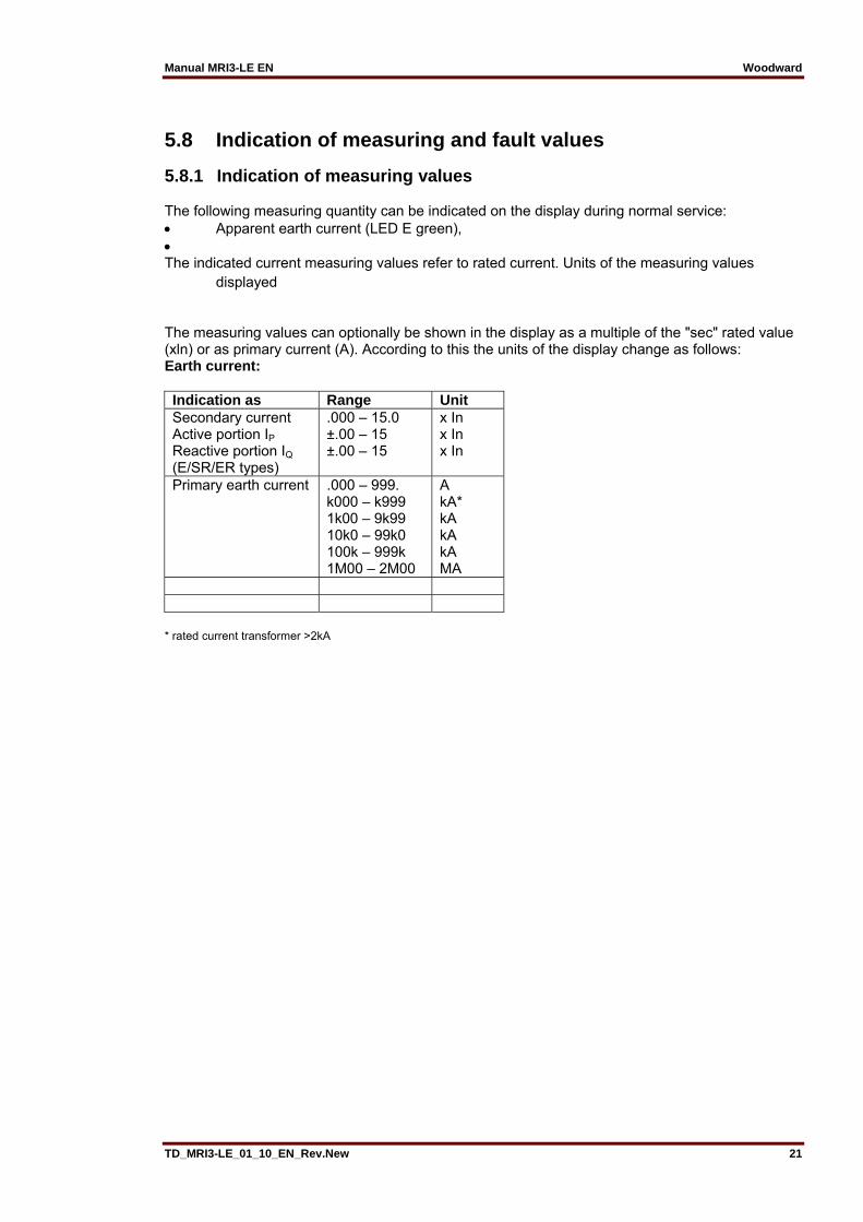
5.8.1 Indication of measuring values The following measuring quantity can be indicated on the display during normal service: Apparent earth current (LED E green), The indicated current measuring values refer to rated current. Units of the measuring values displayed
The measuring values can optionally be shown in the display as a multiple of the "sec" rated value (xln) or as primary current (A). According to this the units of the display change as follows: Earth current: Indication as Range Unit Secondary current Active portion IP Reactive portion IQ (E/SR/ER types)
.000 – 15.0 ±.00 – 15 ±.00 – 15
x In x In x In
Primary earth current .000 – 999. k000 – k999 1k00 – 9k99 10k0 – 99k0 100k – 999k 1M00 – 2M00
A kA* kA kA kA MA
* rated current transformer >2kA
Woodward Manual MRI3-LE EN
22 TD_MRI3-LE_01_10_EN_Rev.New
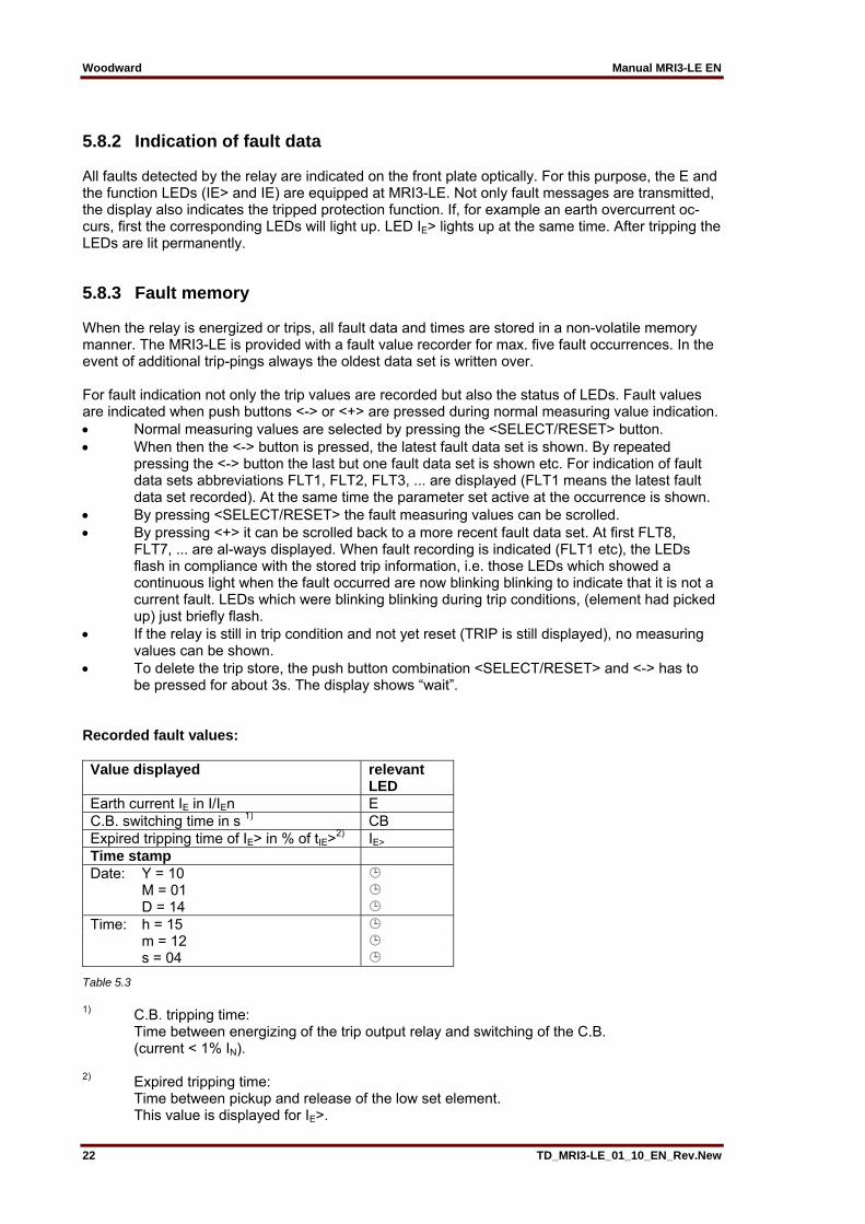
5.8.2 Indication of fault data All faults detected by the relay are indicated on the front plate optically. For this purpose, the E and the function LEDs (IE> and IE) are equipped at MRI3-LE. Not only fault messages are transmitted, the display also indicates the tripped protection function. If, for example an earth overcurrent oc-curs, first the corresponding LEDs will light up. LED IE> lights up at the same time. After tripping the LEDs are lit permanently.
5.8.3 Fault memory When the relay is energized or trips, all fault data and times are stored in a non-volatile memory manner. The MRI3-LE is provided with a fault value recorder for max. five fault occurrences. In the event of additional trip-pings always the oldest data set is written over. For fault indication not only the trip values are recorded but also the status of LEDs. Fault values are indicated when push buttons <-> or <+> are pressed during normal measuring value indication. Normal measuring values are selected by pressing the <SELECT/RESET> button. When then the <-> button is pressed, the latest fault data set is shown. By repeated pressing the <-> button the last but one fault data set is shown etc. For indication of fault data sets abbreviations FLT1, FLT2, FLT3, ... are displayed (FLT1 means the latest fault data set recorded). At the same time the parameter set active at the occurrence is shown. By pressing <SELECT/RESET> the fault measuring values can be scrolled. By pressing <+> it can be scrolled back to a more recent fault data set. At first FLT8, FLT7, ... are al-ways displayed. When fault recording is indicated (FLT1 etc), the LEDs flash in compliance with the stored trip information, i.e. those LEDs which showed a continuous light when the fault occurred are now blinking blinking to indicate that it is not a current fault. LEDs which were blinking blinking during trip conditions, (element had picked up) just briefly flash. If the relay is still in trip condition and not yet reset (TRIP is still displayed), no measuring values can be shown. To delete the trip store, the push button combination <SELECT/RESET> and <-> has to be pressed for about 3s. The display shows “wait”. Recorded fault values: Value displayed relevant
LED Earth current IE in I/IEn E C.B. switching time in s 1) CB Expired tripping time of IE> in % of tIE>2) IE> Time stamp Date: Y = 10 M = 01 D = 14 Time: h = 15 m = 12 s = 04
Table 5.3
1) C.B. tripping time: Time between energizing of the trip output relay and switching of the C.B. (current < 1% IN). 2) Expired tripping time: Time between pickup and release of the low set element. This value is displayed for IE>.
Manual MRI3-LE EN Woodward
TD_MRI3-LE_01_10_EN_Rev.New 23
5.9 Reset Unit MRI3 has the following three possibilities to reset the display of the unit as well as the output relay at jumper position J3=ON. Manual Reset Pressing the push button <SELECT/RESET> for some time (about 3 s) Software Reset The software reset has the same effect as the <SELECT/RESET> push button (see also communication protocol of RS485 interface). The display can only be reset when the pickup is not present anymore (otherwise "TRIP" remains in display). During resetting of the display the parameters are not affected.
5.9.1 Erasure of fault storage The fault storage is erased by pressing the key combination <SELECT/RESET> and <-> for about 3 s. At the display "Wait" appears.
Woodward Manual MRI3-LE EN
24 TD_MRI3-LE_01_10_EN_Rev.New
6. Relay testing and commissioning The test instructions following below help to verify the protection relay performance before or dur-ing commissioning of the protection system. To avoid a relay damage and to ensure a correct relay operation, be sure that: The auxiliary power supply rating corresponds to the auxiliary voltage on site. The rated current and rated voltage of the relay corresponds to the plant data on site. The current transformer circuits and voltage trans-former circuits are connected to the relay correctly. All signal circuits and output relay circuits are connected correctly.
6.1 Power-On NOTE! Prior to switch on the auxiliary power supply, be sure that the auxiliary supply voltage corresponds with the rated data on the type plate. Switch on the auxiliary power supply to the relay and check that the message "SEG" appears on the display and the self supervision alarm relay (watchdog) is energized (Contact terminals D7 and E7 closed).
6.2 Testing the output relays and LEDs NOTE! Prior to commencing this test, interrupt the trip circuit to the circuit breaker if tripping is not desired. By pressing the push button <TRIP> once, the display shows the first part of the software version of the relay (e.g. “D08-”). By pressing the push button <TRIP> twice, the display shows the second part of the software version of the relay (e.g. “4.01”). The software version should be quoted in all correspondence. Pressing the <TRIP> button once more, the display shows "PSW?". Please enter the correct password to proceed with the test. The message "TRI?" will follow. Confirm this mes-sage by pressing the push button <TRIP> again. All output relays should then be activated and the self supervision alarm relay (watchdog) be deactivated one after another with a time interval of 3 second and all LEDs with a delay of 0.5 seconds, with the self-supervision relay dropping. There-after, re-set all output relays back to their normal positions by pressing the push button <SELECT/RESET> (about 3 s).
6.3 Checking the set values By repeatedly pressing the push button <SELECT>, all relay set values may be checked. Set value modification can be done with the push button <+><-> and <ENTER>. For detailed information about that, please refer to chapter 5. For a correct relay operation, be sure that the frequency set value (f=50/60) has been selected ac-cording to your system frequency (50 or 60 Hz).
Manual MRI3-LE EN Woodward
TD_MRI3-LE_01_10_EN_Rev.New 25
6.4 Secondary injection test
6.4.1 Test equipment Voltmeter, Ammeter with class 1 or better, auxiliary power supply with the voltage corresponding to the rated data on the type plate, single-phase current supply unit (adjustable from 0 to ≥ 4 x In), timer to measure the operating time (Accuracy class ≤±10 ms), switching device and test leads and tools.
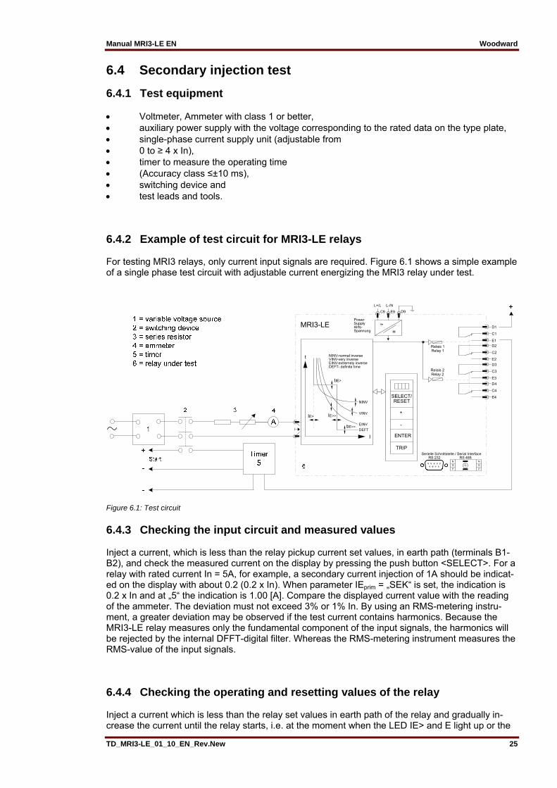
6.4.2 Example of test circuit for MRI3-LE relays For testing MRI3 relays, only current input signals are required. Figure 6.1 shows a simple example of a single phase test circuit with adjustable current energizing the MRI3 relay under test.
Figure 6.1: Test circuit
6.4.3 Checking the input circuit and measured values Inject a current, which is less than the relay pickup current set values, in earth path (terminals B1-B2), and check the measured current on the display by pressing the push button <SELECT>. For a relay with rated current In = 5A, for example, a secondary current injection of 1A should be indicat-ed on the display with about 0.2 (0.2 x In). When parameter IEprim = „SEK“ is set, the indication is 0.2 x In and at „5“ the indication is 1.00 [A]. Compare the displayed current value with the reading of the ammeter. The deviation must not exceed 3% or 1% In. By using an RMS-metering instru-ment, a greater deviation may be observed if the test current contains harmonics. Because the MRI3-LE relay measures only the fundamental component of the input signals, the harmonics will be rejected by the internal DFFT-digital filter. Whereas the RMS-metering instrument measures the RMS-value of the input signals.
6.4.4 Checking the operating and resetting values of the relay Inject a current which is less than the relay set values in earth path of the relay and gradually in-crease the current until the relay starts, i.e. at the moment when the LED IE> and E light up or the
Woodward Manual MRI3-LE EN
26 TD_MRI3-LE_01_10_EN_Rev.New
alarm output relay IE> is activated. Read the operating current indicated by the ammeter. The devi-ation must not exceed 3% of the set operating value or 0.1% In. Furthermore, gradually decrease the current until the relay resets, i.e. the alarm output relay IE> is disengaged. Check that the resetting current is smaller than 0.97 times the operating current.
6.4.5 Checking the relay operating time To check the relay operating time, a timer must be connected to the trip output relay contact. The timer should be started simultaneously with the current injection in the current input circuit and stopped by the trip relay contact. Set the current to a value corresponding to twice the operating value and inject the current instantaneously. The operating time measured by the timer should have a deviation of less than 3% of the set value or ±15 ms (DEFT). Accuracy for inverse time characteristics refer to IEC 255-3. Repeat the test with the inverse time characteristics in the similar manner. In case of inverse time characteristics the injected current should be selected according to the characteristic curve, e.g. two times Is. The tripping time may be red from the characteristic curve diagram or calculated with the equations given under "technical data". Please observe that during the secondary injection test the test current must be very stable, not deviating more than 1%. Otherwise the test results may be wrong.
6.4.6 Checking the high set element of the relay Set a current above the set operating value of IE>>. Inject the current instantaneously and check that the alarm output relay IE>> operates. Check the tripping time of the high set element according chapter 6.4.5. Check the accuracy of the operating current setting by gradually increasing the injected current un-til the IE>> element picks up. Read the current value form the ammeter and compare with the de-sired setting. Note ! Where test currents >4 x IN are used, the thermal with-stand capability of the current paths has to be considered (see technical data, chapter 7.1).
6.5 Primary injection test Generally, a primary injection test could be carried out in the similar manner as the secondary in-jection test described above. With the difference that the protected power system should be, in this case, connected to the installed relays under test “on line”, and the test currents should be injected to the relay through the current transformers with the primary side energized. Since the cost and potential hazards are very high for such a test, primary injection tests are usually limited to very im-portant protective relays in the power system.
6.6 Maintenance Maintenance testing is generally done on site at regular intervals. These intervals vary among us-ers depending on many factors: e.g. the type of protective relays employed; the importance of the primary equipment being protected; the user's past experience with the relay, etc. For electromechanical or static relays, maintenance testing will be performed at least once a year according to the experiences. For digital relays like MRI3-LE, this interval can be substantially longer. A testing interval of two years for maintenance will, therefore, be recommended. During a maintenance test, the relay functions including the operating values and relay tripping characteristics as well as the operating times should be tested.
Manual MRI3-LE EN Woodward
TD_MRI3-LE_01_10_EN_Rev.New 27
7. Technical data
7.1 Measuring input circuit Rated data: Nominal current IN 1 A or 5 A Nominal frequency fN 50 Hz; 60 Hz adjustable Power consumption in current circuit: at IN = 1 A 0.2 VA at IN = 5 A 0.1 VA Thermal withstand capability in current circuit: dynamic current withstand (half-wave) 250 x IN for 1 s 100 x IN for 10 s 30 x IN continuously 4 x IN
7.2 Common data Dropout to pickup ratio: >97% Dropout to pickup ratio for phase current in range 0.2 x IN to 0.5 x IN: = 100 % Returning time: 30 ms Minimum operating time: 30 ms Transient overreach at instantaneous operation: ≤5% Influences on the current measurement Auxiliary voltage: in the range of 0.8 <UH/UHN <1.2 no additional influences can be measured Frequency: in the range of 0.9 < f/fN < 1.1; <0.2% / Hz Harmonics: up to 20% of the third harmonic; <0.08% per percent of the third harmonic up to 20% of the fifth harmonic; <0.07% per percent of the fifth harmonic Influences on delay times: no additional influences can be measured

Woodward Manual MRI3-LE EN
28 TD_MRI3-LE_01_10_EN_Rev.New
7.3 Setting ranges and steps System parameter
Setting range Step ToleranceIEprim (SEK)
0.001...50.0KA 0.001; 0.002; 0.005; 0.01; 0.02; 0.05; 0.1; 0.2
7.3.1 Earth fault protection Setting range Step ToleranceIE> tIE>
0.01...2.0 x IN (EXIT) 0.03...260 s (EXIT) (definite time) 0.05...10 (EXIT) (inverse time)
0.001; 0.002; 0.005; 0.01; 0.02; 0.05 xIN0.01; 0.02; 0.05; 0.1; 0.2; 0.5; 1.0; 2.0; 5.0; 10; 20 s 0.01; 0.02; 0.05; 0.1; 0.2
5% from set value or 0.3% IN 3% or ±15 ms 3% of the measuring value of the current or 20 ms (see EN60255-3)
IE>> tIE>>
0.01...15.0 x IN (EXIT) 0.03...10 s (EXIT)
0.001; 0.002; 0.005, 0.01; 0.02; 0.05; 0.1; 0.2; 0.5 xIN 0.01; 0.02; 0.05 s; 0.1 s; 0.2 s
5% from set value or 0.3% IN 3% or 15 ms
7.3.2 CBFP Circuit breaker failure protection protection
tCBFP 0.1...2.0 s; EXIT 0.01; 0.02; 0.05; 0.1 s ±1% or ±10 ms
7.3.3 Interface parameter
Function Parameter Modbus-ProtocolRS Slave-Adresse 1 - 32 RS Baud-Rate* 1200, 2400, 4800, 9600 RS Parität* even, odd, no
7.3.4 Parameter for the fault recorder
Function Parameter Adjustment exampleFR Number of recordings (1)* 2 x 8 s; (3)* 4 x 4 s; (7)* 8 x 2 s (50 Hz)
(1)* 2 x 6.66 s, (3)* 4 x 3.33 s, (7)* 8 x 1.66 s FR Saving of the recording at the occurrence P_UP; TRIP; A_PI; TEST FR Pre-trigger time 0.05 s – 8.00 s
* is written over at new trigger signal

Manual MRI3-LE EN Woodward
TD_MRI3-LE_01_10_EN_Rev.New 29
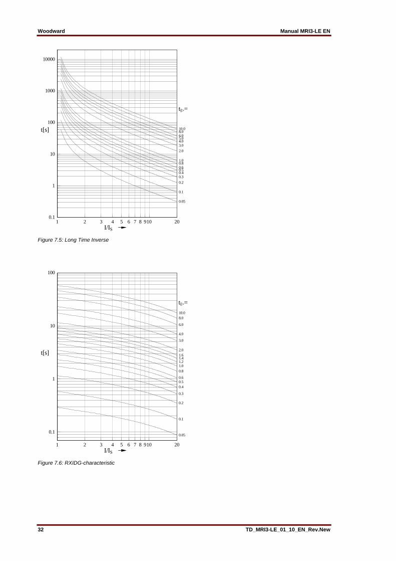
7.3.5 Inverse time overcurrent protection relay According to IEC 255-4 or BS 142 Normal Inverse (Type A)
0.14.
1·
Very Inverse (Type B)
13.5
1·
Extremely Inverse (Type C)
80
1·
Long Time Inverse
120
1·
RI-Inverse Time
1
0.3390.236 ·
RXIDG – characteristic
5.8 1.3 · ℓ ·
Where: t = tripping time tI> = time multiplier I = fault current Is = Starting current ℓ = natural logarithm

Woodward Manual MRI3-LE EN
30 TD_MRI3-LE_01_10_EN_Rev.New
7.4 Inverse time characteristics
Figure 7.1: Normal Inverse (Type A)
Figure 7.2: Very Inverse (Type B)
1 2 3 4 5 6 7 8 910 20I/IS
0.1
1
10
100
1000
t[s]
tI>=
0.05
0.1
0.2
0.30.40.50.60.81.0
1.4
2.0
3.04.0
6.08.010.0
1 2 3 4 5 6 7 8 910 20I/IS
0.1
1
10
100
1000
t[s]tI>=
0.05
0.1
0.2
0.30.40.50.60.81.0
10.0
1.4
2.0
3.04.0
6.08.0
Manual MRI3-LE EN Woodward
TD_MRI3-LE_01_10_EN_Rev.New 31
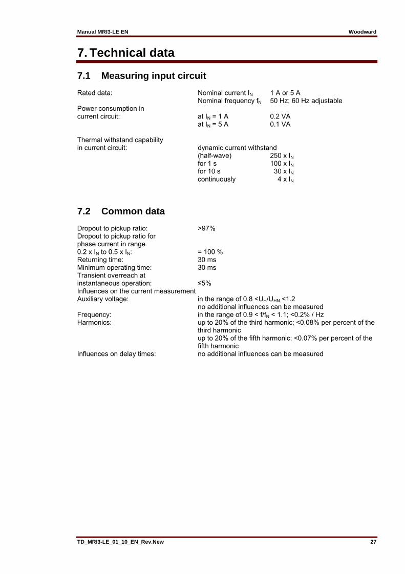
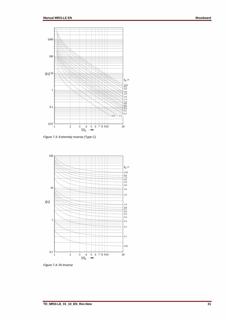
Figure 7.3: Extremely Inverse (Type C)
Figure 7.4: RI-Inverse
1 2 3 4 5 6 7 8 910 20I/IS
0.01
0.1
1
10
100
1000
t[s]
tI>=
0.050.05 0.10.10.20.30.40.50.60.81.0
10.0
1.42.03.04.06.08.0
1 2 3 4 5 6 7 8 910 20I/IS
0.1
1
10
100
t[s]
tI>=10.0
8.07.06.05.0
4.0
3.0
2.0
1.0
0.80.70.60.5
0.4
0.3
0.2
0.1
0.05
Woodward Manual MRI3-LE EN
32 TD_MRI3-LE_01_10_EN_Rev.New
Figure 7.5: Long Time Inverse
Figure 7.6: RXIDG-characteristic
1 2 3 4 5 6 7 8 910 20I/IS
0.1
1
10
100
1000
10000
t[s]
tI>=
1.0
2.0
10.08.06.05.04.03.0
0.80.60.50.40.3
0.2
0.1
0.05
1 2 3 4 5 6 7 8 910 20I/IS
0.1
1
10
100
t[s]
tI>=
8.0
6.0
3.0
4.0
2.01.6
1.0
1.41.2
10.0
0.8
0.60.50.4
0.3
0.2
0.1
0.05
Manual MRI3-LE EN Woodward
TD_MRI3-LE_01_10_EN_Rev.New 33
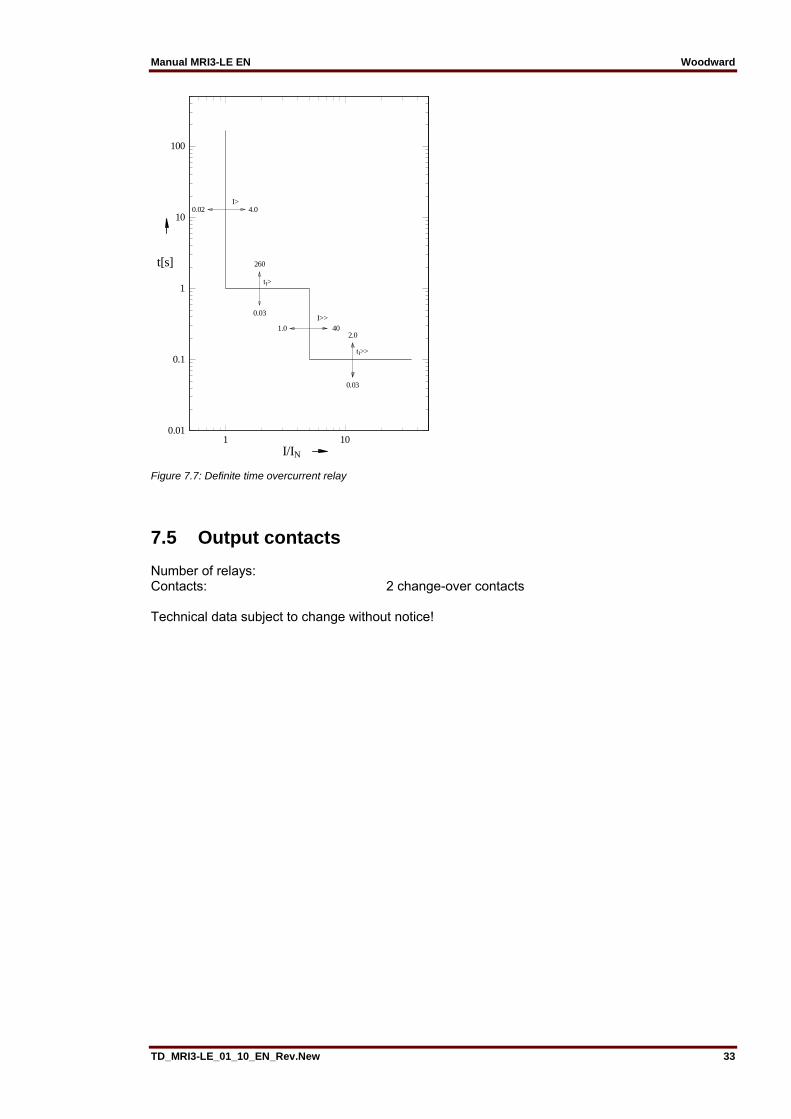
Figure 7.7: Definite time overcurrent relay
7.5 Output contacts Number of relays: Contacts: 2 change-over contacts Technical data subject to change without notice!
1 10I/IN
0.01
0.1
1
10
100
t[s]
tI>tI>
I>>I>>
tI>>tI>>
260260
0.030.03
1.01.0 40402.02.0
0.030.03
0.020.02 4.04.0I>I>
Woodward Manual MRI3-LE EN
34 TD_MRI3-LE_01_10_EN_Rev.New
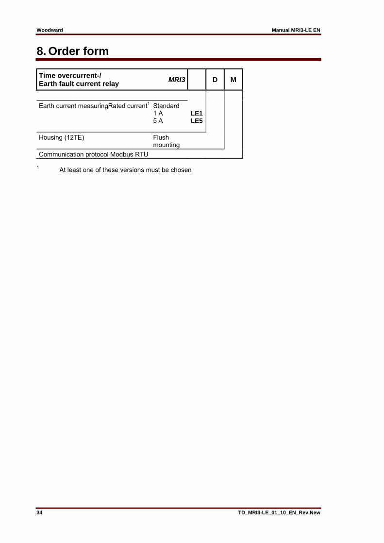
8. Order form
Time overcurrent-/ Earth fault current relay
MRI3 D M
Earth current measuringRated current1 Standard 1 A 5 A
LE1LE5
Housing (12TE) Flush mounting
Communication protocol Modbus RTU 1 At least one of these versions must be chosen

Manual MRI3-LE EN Woodward
TD_MRI3-LE_01_10_EN_Rev.New 35
Setting list MRI3-LE Note ! All settings must be checked at site and should the occasion arise, adjusted to the object / item to be protected. Project: SEG job.-no.: Function group: = Location: + Relay code: - Relay functions: Password: Date: Adjustment of the parameter Systemparameter Relay type MRI3-LE Default settings Actual settingsIprim (earth) SEK 50/60 Hz 50Hz Indication Pickup FLSH Parameter switch/external triggering for the fault recorder
SET1
Protection parameter Relay type MRI3-LE Default settings Actual settings2 parameter sets Set 1/Set 2 Set 1/ Set 2 IE> 0.01 xIn trip/warn Trip CHAR IE DEFT tIE> 0.04s 0s/60s 0s IE>> 0.01 xIn tIE>> 0.04s tCBFP EXIT RS485 / RS232/Slave 1 Baud-Rate 9600 Parity-Check even Fault recorder
Function Unit Default set-tings
Actual settings
FR Number of recordings 4 FR Saving of the recording at the occur-
rence TRIP
FR Time prior to trigger impulse s 0,05 Year settings Year Y = 00 Month settings Month M=00 Day settings Day D=00 Setting of the hours Hours h=00 Setting of the minutes Minutes m=00 Settings of the seconds Seconds s=00

Woodward Manual MRI3-LE EN
36 TD_MRI3-LE_01_10_EN_Rev.New
Setting of code jumpers
Code jumper J1 J2 J3 Default
settings Actual
settings Default settings
Actual settings
Default setting
Actual settings
Plugged No plugged X No function X
Assignment of the output relays:
Function Relay 1 Relay 2 Default
setting Actual setting
Default setting
Actual setting
IE> Alarm X tIE> Tripping X IE>> Alarm X tIE>> Tripping X tCBFP Tripping
This technical manual is valid for Software version: Modbus version number: D88-1.00
Woodward SEG GmbH & Co. KG Krefelder Weg 47 D – 47906 Kempen (Germany)
Postfach 10 07 55 (P.O.Box) D – 47884 Kempen (Germany) Phone: +49 (0) 21 52 145 1
Internet
Homepage http://www.woodward-seg.com Documentation http://doc.seg-pp.com
Sales
Phone: +49 (0) 21 52 145 -636 or -319 Telefax: +49 (0) 21 52 145 354 e-mail: [email protected]
Service
Phone: +49 (0) 21 52 145 -334 or -614 Telefax: +49 (0) 21 52 145 455 e-mail: [email protected]