mps experience at bnl-rhic - frib.msu.edu · pdf filemps experience at bnl-rhic bnl collider...
TRANSCRIPT

MPS Experience at BNL-RHIC
BNL Collider Complex Overview
MPS at the collider acceleratordepartment (C-AD)
RHIC Accelerator Protection Elements
Operational Experience
Summary

BNL Collider Complex Overview

BNL Collider Complex Overview
MPS at C-AD
RHIC Accelerator Protection Elements
Operational Experience
Summary

MPS at C-AD
The Machine Protection Systems at BNL are very mature. Conception and implementation for the pre-injectors was established long ago, before the RHIC-era. The RHIC MPS was designed in the 1990’s and leveraged strongly off the experiences from FNAL.
This talk will present the machine protections systems of the presently operating accelerator facilities at C-AD.
The Machine Protection System at BNL consists of three parts:
1) input measurements (and subsystem interlock systems) 2) beam interlock system (“permit system”)3) consequences: mechanisms for preventing beam into regions of
interest (injectors) or dumping the beams (in RHIC)

Presently there are 5 permit links (which are not interdependent) and a stand-alone MPS for the linac.
RHIC
NSRLLINAC
Booster AGS
EBIS
#1 Booster prevent beam in the NSRL line / acceleration in Booster
Permit Link Function
#2 AGS prevent accelerating beam in the AGS
#3 AtR (U/V/W) prevent beam from entering the AtR line
#4 Arc prevent beam from entering RHIC
#5 RHIC eliminate circulating beam in RHIC
AGS-to-RHIC transport (AtR)
These protect the accelerators from damage due to the beam. At RHIC, the superconducting magnets are also protected from the release of stored energy by quench protection links.

Booster MPS
20
0 M
eV
LIN
AC
H-50 mA
(polarized) protons1 nA
NSRL (NASA Space Radiation laboratory)
EBISHe to Au~ 2 mA
BOOSTERAGS
12 M
V L
IN
AC
~ 1 GeV/A Au~ 2.3 GeV pol protons
prevents beam in the NSRL line and acceleration in the Booster
R-Line

vacuum valves (R-line)vacuum valves* (Booster)
power supply status (R-line)
The Booster permit link system also allows for inhibiting beam to R-Line while allowing beam in Booster for other Booster-users (e.g. AGS and/or other Booster beam development)
input measurements
consequences booster RF drive signal set to zero R-Line extraction bumps inhibitedmain magnet power supply ramped up to spiral beam
into dump
condition for beam inhibit
valves closedvalves closed
on/off status fault
dose on NSRL target sample(measured using ion chambers)
desired dose achieved
Booster MPS
PLCs
* (reachback to chopper in linac fast-beam inhibit system)

Booster Permit Link configuration and status
inputs status of inputs input enable/disable
link monitoringstatus
example operator level readbacks

AGS MPS
BOOSTER AGS~ 1 GeV/A Au~ 2.3 GeV pol
protons
~ 10 GeV/A Au~ 24 GeV pol
protons
prevents accelerating beam in the AGS
vacuum valvesloss monitor managerloss monitors at sensitive locations magnet (“snake”) quench detectordump bump power supply status
input measurements
consequences AGS RF drive signal set to zero extraction bumps inhibitedif operating with polarized protons, source is inhibited
condition for beam inhibit
valve closedbeam loss exceeds thresholdbeam loss exceeds thresholdquench eventon/off status fault
beam current transformer (2 units)
transformer keep-alive statuses
beam current exceeds threshold (and AtR dipoles on)
status fault
BtA

U/V/W (Accelerator to RHIC) MPS
AGS~ 10 GeV/A Au~ 24 GeV pol
protons
prevents beam from entering the AtR line
ARC MPS prevents beam from entering RHIC
RHIC~ 100 GeV/A Au~ 250 GeV pol
protons
input measurements
consequences extraction kicker triggers from AGS disabled
condition for beam inhibit
vacuum valves valve closed
PASS (aka PPS) status, division APASS status, division B
access control state not in “no access”
input measurements
consequences switching magnet turned off
condition for beam inhibit
vacuum valves valve closed
RHIC permits to the arc
Blue magnet quench detectorYellow magnet quench detector
quench eventquench event
fault

RHIC MPS eliminates circulating beam in RHIC
RHIC
~ 100 GeV/A Au~ 250 GeV pol
protons
input measurements
consequences RHIC abort kickers triggered
condition for beam inhibit
loss monitorsvacuum valves
power supply status
beam loss exceeds thresholdvalve closed
on/off status fault
roman pot positions (both rings)beam loss at roman pots
position errorbeam loss exceeds threshold
RF cavity voltage voltage status fault
PASS (aka PPS) status, division APASS status, division BPASS Beam Stop status (A and B)
access controls state not in “no access”
Blue magnet quench detector Yellow magnet quench detector
quench detector (snakes and rotators)
quench eventquench event
quench event
PLCs

BNL Collider Complex Overview
MPS at C-AD
RHIC Accelerator Protection Elements
Operational Experience
Summary

RHIC Accelerator Protection Elements
Equipment monitoring systemsBeam monitoring systemsBeam interlock system (“permit system”) Beam dumping system
(collimation and “gap cleaning” primarily for detector backgrounds)
Equipment monitoring systems
Conventional: vacuum valves, vacuum pump status, power supply outputs,…
RHIC specific: superconducting magnet quench protection system

RHIC superconducting magnet quench protection system
one QD in every arc’s center alcovemonitoring voltage taps in the arcs
two QDs in service buildings monitoringmagnet and lead voltage taps in theinsertion regions
voltage readout at 720 Hz
consists ofquench detectorsquench protection assembly
(and interface chasses)quench protection switchesquench link (one link per ring)

Beam monitoring systems: beam loss monitors (BLM)
~ 430 gas ionization chambers (RHIC)~ 100 in AGS to RHIC transfer line
based on Tevatron design (R. Shafer)
For MPS:
Other beam loss diagnostics:pin diodes (Bergoz) photomultiplier tubes (JLAB-CEBAF design)
BLM data handling, two paths:
(1) to MADCs (1 Hz averaged data for logging, 720 Hz for post mortem analyses) (2) to pair of threshold detectors (comparators) for detection of
slow losses (time constant ~ 20 ms)fast losses (time constant ~ 100 ms)
which produce an inhibit if threshold is exceeded

Beam monitoring systems: beam current monitors
Pair (for redundancy) of back-to-back Bergoz NPCTs with internal keep-alive circuit (constant 15 mA rms / 65 mV rms, 31.25 kHz signal). Fault produced if current exceeds threshold or if keep-alive current not measured.
Plan for ERL: pair of Bergoz New Parametric Current Transformers (NPCT) for differential beam loss measurement
assembly in shop as installed in the AGS

Beam interlock system
consists of 10 MHz carrier(s)3 permit links (2 for QDs, 1 for all else)32 beam interlock controllers (BIC)up to 192 distributed “user system” inputs 1 dedicated “master” to initiate establishment of a permit
Full system tests on demand (typically during startup)Max response time (permit failure to abort) ~ 40 microseconds or ~ 3.2 turns
BIC, conceptual view BIC FEClist QD link inputs

Beam dumping system
consists of kicker magnetspulse forming networks (PFNs) dump absorber
design assumptions: Emax = 200 kJ at 100 GeV/A with Nb=60, Nppb=1E9 (Au)
concern: secondary particle emission from dump absorber could heat and quench downstream superconducting magnets
response time: charging supply for PFN disconnect ~ 10 ms (~ 1 turn) trigger synchronization (~ 1 turn)(plus transit time from permit link ~ 3 turns 5 turns total or 60 ms)
RHIC blue dump kicker assemblies RHIC blue beam dump

BNL Collider Complex Overview
MPS at C-AD
RHIC Accelerator Protection Elements
Operational Experience
Summary

Operational Experience
The well-established C-AD MPS system generally works as expected.
There may be more permit pulls than necessary, but not excessively so.
“Failures” of the MPS concern dynamics either not considered in the MPS design or result from operation with beam intensities higher than envisioned in the MPS design.
These lessons learned will be reviewed next.

AGS beam-induced vacuum failures (2008)
Issue operation with 4 Au bunches, 5E9 ppb resulted in 3 vacuum leaks
Remediesdump moved closer to beamplunging stripping foil implemented
motivation: force Au ions to lose 2 remaining electrons in 1 mil Tungsten foil resulting in beam rigidity decrease and hencelarger deflection due to dump bump
Recent issue (2014): MPS designed to inhibit beam to downstream systems but not to protect the accelerator from itself (plethora of spurious BLM readings causing beam inward spiral during acceleration due to rf turn-off strategy)
dump bump amplitude increased
AGS beam dump AGS plunging stripping foil

RHIC quenches due to beam aborts (2010)
Issue beam aborts at high energy caused quenching of magnets downstreamof dump
Remedies
simulations: no quenches for up to 2.5E11 ppb (250 GeV protons)
additional BLMs installed (subsequently determined desire for lesssensitive BLMs avoiding saturation during an abort as potentiallyuseful in understanding beam abort dynamics)
additional absorbers (20 5-inch sleeves) installed in the RHIC beam pipe adjacent to the dump to increase wall thickness
no abort-induced quenches in following year of operations
dump shielding sleeve

RHIC quenches due to beam aborts (2013)
Remedies actively being investigated
Issue quenches caused by beam abort
Observations
measured abort kicker currents does not track with new fast-sampled beam position measurements
measured abort kicker currents different (during operations and maintenance days)
plan for major abort kicker upgrades in summer, 2014
inductance of ferrites changes with beam-induced temperature rise
Diagnosis
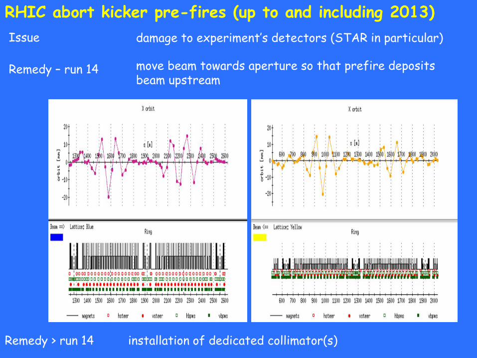
RHIC abort kicker pre-fires (up to and including 2013)
Remedy – run 14
Issue damage to experiment’s detectors (STAR in particular)
move beam towards aperture so that prefire deposits beam upstream
Remedy > run 14 installation of dedicated collimator(s)

Summary
• The RHIC physics program entails a very wide variety of particle species and energies
• The MPS design for the C-AD preinjectors is mature, maybe rudimentary by today’s standards, but robust
• Ever-increasing beam intensities required by the evolving requirements of the physics programs have motivated and continue to motivate MPS sub-system upgrades
• A new era of MPS systems is under development at C-ADfor (electron-based) new projects including electron lenses, “conventional” electron cooling, coherent electron cooling (new), and the energy recovery linac project

Acknowledgements (for this presentation)
For MPS as seen by Operations throughout the accelerator complex: Travis Shrey
For user-distributed inputs: general: Travis Shrey and Greg Marr (Operations)
+ Loralie Smart (Vacuum)+ John Butler (RF)+ Don Bruno (Power Supplies, Quench Detection)+ David Gassner, Peter Oddo, Michelle Wilinski (Beam Instrumentation)
For photographs: Don Bruno, Dave Gassner, Paul Sampson, Joe Tuozzolo
For beam permit system: Kevin Brown, Peter Ingrassia, Travis Shrey, Charles Theisen
For RHIC beam dump: RHIC Configuration Manual (2006)
For operational experience: AGS vacuum issues – Leif AhrensRHIC quenches due to beam aborts, 2010 – Christoph MontagRHIC quenches due to beam aborts, 2013 –Rob Hulsart, Rob Michnoff,
Peter ThiebergerRHIC abort kicker prefires, 2013 – Angelika Drees, Christoph Montag,
Rob Hulsart, Aljosa Marusic, Rob Michnoff, Peter Thieberger, Simon White

Current and Future Developments in Controls
A stand-along MPS system for the Electron Beam Ion Source (EBIS), called EGIS, was developed by Omar Gould
Also under development is a stand-alone quench detection system for the ERL superconducting solenoids (using NI PXIe platform)
MPS designs for future projects Energy Recovery Linac (ERL)electron lensnew 56 MHz SC cavity for RHICCoherent Electron Cooling
are being developed using NI CompactRIO platforms
The Controls portion of the MPS for these systems is being developed by:
Zeynep Altinbas, Mike Costanzo, Chung Ho and Charles Theisen (systems design and permit link boards)
Jim Jamilkowski, and Prerana Kankiya (ADO manager interfaces)Peggy Harvey (MPS interfaces to rf systems) Prachi Chitnis (student, reliability analysis)

spare slides
Quench protection in RHIC

Preparation for higher beam intensities: beam position monitors
Issue The “cold” BPM cables (those located in the insulating vacuum) consist of a stainless steel outer conductor with a “tefzel” dielectric. If the beam-induced power is too large, this dielectric will melt.
BPM excursion monitor developed based on absolute BPM measurements (striplines)
achieved bunch length
limitation by cryogenic system
nominal intensity intensity after upgrades