mpls based layer 2 virtual private network services · mpls based layer 2 virtual private network...
TRANSCRIPT

MPLS based Layer 2 Virtual Private Network
Services
Florin Balus, Mike Loomis February 8, 2004
[email protected]@nortelnetworks.com

PG 1Florin Balus & Mike Loomis NANOG30, Miami
L2 VPNs and Related Standards
Point to point
LDP VPLS
BGP VPLS
LDP SignalingMartini Circuits
RFC 2547
VPWS
L2VPNs
PWE3
PPVPN
BGP Auto-discovery
Pseudo-wiresAny to any
L2 Service Mediation
Single Sided ProvisioningL2 Service
Interworking
PWid vsGid FEC
ARP Mediation
A lot of New Terms, Confusion in the Industry

PG 2Florin Balus & Mike Loomis NANOG30, Miami
ScopeThis presentation will …• Explain the motivation behind the Layer 2 over MPLS technology• Go over the related Technical Concepts, Standards
technologyL2 over MPLS
The Goal is to help you …• understand the technology, latest developments• determine applicability to your business model• be ready to implement it
market
standards
customers
Focus on the technology side: How Does it Work?

PG 3Florin Balus & Mike Loomis NANOG30, Miami
Agenda
• Introduction to L2VPNs over MPLS• Drivers, Definitions, Standards
• IETF Generic Models (L2VPNs)• Virtual Private Wire Service (VPWS)• Layer 2 Service Interworking• Virtual Private LAN Service (VPLS)• Summary

PG 4Florin Balus & Mike Loomis NANOG30, Miami
Drivers for L2VPN over MPLSBackbone Convergence – Present Mode of Operation
Ethernet Access
Leased Line Access
Broadband Access
L2 Access
Edge Router
L2 Aggregation
ATM Core
IP Core
MPLS Core
Network EdgeAccess Networks Network Core
Cap existing access aggregation and edge nodes where it makes sense
Multiple access networks connected to multiple cores. Equates to complex management / high costs

PG 5Florin Balus & Mike Loomis NANOG30, Miami
Drivers for L2VPN over MPLSBackbone Convergence - Any Access, Any Service/MPLS
MPLS Edge
MPLS Core
MSE
New service growth
Leased Line Access
Ethernet Access
L2 access
Existing infrastructure
Broadband Access
Service GatewaysInternet, Data Center Access, Multimedia Distribution Center
Access Networks MPLS Core
• Support growth of new services – i.e. IP VPNs, Triple Play, Ethernet L2• Support growth of new services – i.e. IP VPNs, Triple Play, Ethernet L2• Interwork to existing “Cash Cows” – i.e. ATM, FR, Existing DSL Networks…

PG 6Florin Balus & Mike Loomis NANOG30, Miami
Drivers for L2VPN over MPLS Evolution of Ethernet Services
Ethernet Metro
Ethernet Access
Ethernet Access
ATM/FR
Martini Access
MSE
IP/MPLS
MSE
MSE
• Existing Ethernet build-outs - a limited scope• Difficulties with Ethernet to ATM/FR Interworking
• Expanding the coverage, scope via MPLS• Ethernet to FR/ATM Interworking – Protocol, QoS, OAM, Resiliency• Evolving to Consolidated, NextGen Access – Ethernet over Martini PWs

PG 7Florin Balus & Mike Loomis NANOG30, Miami
Virtual Private Wire Service (VPWS)Enterprise Perspective
CE3 CE1Service Provider
Backbone
CE4 CE2
CE4
CE1
CE3
CE2
Same Service as Traditional (ATM/FR) L2VPN

PG 8Florin Balus & Mike Loomis NANOG30, Miami
Virtual Private LAN Service (VPLS)Enterprise Perspective
Service Provider Backbone
“Carrier Grade” LAN Emulation Solution

PG 9Florin Balus & Mike Loomis NANOG30, Miami
Standards Scene
ProtocolSpecifications
Architecture/Solutions, Education/Awareness,
& Interoperability
InternationalEnd-2-End
Specifications

PG 10Florin Balus & Mike Loomis NANOG30, Miami
New L2 VPNs & Related IETF Working Groups
Working Groups
VPWSVPLS
ProvisioningAuto-discoverySignalingData planeOAM, Resiliency...
2547, 2764, IPSec VPNs
L2VPNAreas
InternetL3VPN
Point to point Transport,Different Encaps (Ethernet, ATM, FR, TDM), OAM, TM
PWE3Transport
Signaling: LDP, RSVP-TEData Plane - Label Stacking…Resiliency, TM, OAM…
Routing MPLS

PG 11Florin Balus & Mike Loomis NANOG30, Miami
Agenda
• Introduction to L2VPNs over MPLS• IETF Generic Models (L2VPNs)• Virtual Private Wire Service (VPWS)• Layer 2 Service Interworking• Virtual Private LAN Service (VPLS)• Summary
PG 12Florin Balus & Mike Loomis NANOG30, Miami
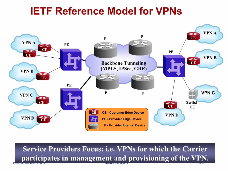
IETF Reference Model for VPNs
Backbone Tunneling(MPLS, IPSec, GRE)
VPN A
VPN B
VPN D
VPN A
VPN B
VPN D
PE
PE
PE
CE
CE
CE
CE
CE
CE
CE P
P
CE - Customer Edge Device
PE - Provider Edge Device
P - Provider Internal Device
CE
VPN C VPN C
Switch CE
CE
CE
P
P
CE
Service Providers Focus: i.e. VPNs for which the Carrier participates in management and provisioning of the VPN.

PG 13Florin Balus & Mike Loomis NANOG30, Miami
Building Blocks for L2 VPN Provisioning, Control Plane
Backbone (MPLS)
PE2(Dallas)
VPN1 1.Config
2. Auto-discovery (BGP) Control Plane
Control Plane
3. Signaling (LDP/BGP)Control Plane
Control Plane
VPN1 1.Config
4. Data Plane
4. Data Plane
PE1(Miami)
New Site
CE CE
1. I want to add a new member of Blue VPN in PE1?• Provision (Setup) the local interface(s) and the required membership info
2. What is the Blue VPN community, where are the others related PEs?• Auto-discovery/Provisioning – provides the list of “locations” for “Blue” Entities
3. How are links established between Endpoints (i.e. Sites)?• Signaling – sets up the path between VPN entities
4. How are packets moved between sites?• Data Plane – procedures related to packet forwarding

PG 14Florin Balus & Mike Loomis NANOG30, Miami
Building Blocks for L2 VPN Data Plane Components, Terminology
Access(Eth/ATM/FR/MPLS)
Access(Eth/ATM/FR/MPLS)
Backbone (MPLS)PE1 PE2
(Miami) (Dallas)
VF11
ACsACs CE CE
CE CE
TL12
TL21
VF21
VCL12
VCL21
CE CE
• Tunnel (Labels - TL) – The path between PE1 and PE2
• Attachment Circuits (AC) – L2 connection between CE and PE• i.e. FR DLCIs, ATM VCs, VLAN Qtags
• Virtual Forwarders (VF) – Service specific processing, forwarding• i.e. same type of functionality as 2547 VRFs
• (MPLS) Pseudo-wire – Paths between VFs = (VC Label -VCL, TL)• Pseudo-wire End Service = pair of unidirectional LSPs

PG 15Florin Balus & Mike Loomis NANOG30, Miami
IETF L2 VPN Model Data Plane Encapsulation – Ethernet Example
Ethernet Access
CE
Ethernet Access
CE
VC Label
Control Control WordWord
“Martini, PWE3”PW Encapsulation
Tunnel Label
MPLS Labels
Ethernet Frame
Local Header(i.e. Ethernet, PoS)
(Miami) (Dallas)
VF11 VF21VCL12
TL12
MPLS Backbone
PE2PE1
Same procedure, encapsulation format in the reverse direction Different Encapsulations Handled in IETF PWE3 Working Group

PG 16Florin Balus & Mike Loomis NANOG30, Miami
Agenda
• Introduction to L2VPNs over MPLS• IETF Generic Models (L2VPNs)• Virtual Private Wire Service (VPWS)• Layer 2 Service Interworking• Virtual Private LAN Service (VPLS)• Summary

PG 17Florin Balus & Mike Loomis NANOG30, Miami
VPWS Agenda
Individual Pt2pt Virtual CircuitsSolutions for Migrating Legacy L2 Services to MPLS
Individual Pt2pt Virtual Circuits– Double Sided, Single Sided Provisioning
• Provisioning Model, Signaling, Packet Walkthrough, Configuration Examples– Pseudo-wire OAM
Solutions for Migrating Legacy L2 Services to MPLS
Focus on the different Information Models, Provisioning Steps• Similar Procedures in the Control and Data Plane

PG 18Florin Balus & Mike Loomis NANOG30, Miami
Individual Point-to-point VCsLogical Service View (Simplified)
Service Provider Network CE2 CE1
Enterprise perspective of the Service – ATM/FR VC, Ethernet VLAN• known also in the industry as Martini Pseudo-wires

PG 19Florin Balus & Mike Loomis NANOG30, Miami
Individual Point-to-point VCsDouble Sided Provisioning – Control & Data Plane
ACMPLS
VF11 (AI)
LDP LDP
CE CEAC VF11
(AI)
PE1(Miami) PE2 (Dallas)
PW Signaling
• No Auto-discovery, just LDP for PW Signaling• Simple Forwarder – forwards everything between 1 PW and 1 AC

PG 20Florin Balus & Mike Loomis NANOG30, Miami
Double Sided ProvisioningConfiguration Example – generic steps
CEGE/10
VLAN/100
MPLSPE1(Miami)
PE2
VF11 (AI)
VF11 (AI)
VF21VF11
CEGE/20 VLAN/200
1. Local Configuration • AC = GE/20 VLAN/2002. Information related to PW Setup
TL=20
TL=10(Dallas)
1’. Local Configuration • AC = GE/10 VLAN/1002’. Information related to PW Setup
Next - LDP signaling will setup the PW • using the FEC to identify the PW the VC Label is bound to

PG 21Florin Balus & Mike Loomis NANOG30, Miami
LDP Signaling - Forward Equivalence Class
MPLS
IP FEC = 47.0.0.0/8LDP LDP
Use Label (LSP) 200 to get to 40
200 “L2” FEC = 40 (GE/20 VLAN/200)A
LSR
Use Label (LSP) 40to get to 47.0.0.0/8
30
Use Label (LSP) 30to get to 47.0.0.0/8
LDP Label Mapping
FEC = “Forwarding Equivalence Class”: a set of packets that are forwarded in the same manner by a MPLS LSR
– Initial usage: a specific entry from the routing table (i.e. IP Host)
FEC = “Forwarding Equivalence Class”: a set of packets that are forwarded in the same manner by a MPLS LSR
– Initial usage: a specific entry from the routing table (i.e. IP Host)
• L2VPNs – FEC used to identify a particular PW that a particular VC label is bound to
FEC = “Forwarding Equivalence Class”: a set of packets that are forwarded in the same manner by a MPLS LSR
– Initial usage: a specific entry from the routing table (i.e. IP Host)
• L2VPNs – FEC used to identify a particular PW that a particular VC label is bound toTwo FECs being defined for PWs/VPWS, VPLS – see draft-ietf-pwe3-control-protocol-03.txt
• PWid FEC - historically first one to be specified (initial “Martini” Control Plane)• Generalized ID FEC (Gid FEC)

PG 22Florin Balus & Mike Loomis NANOG30, Miami
Pseudo-wire Setup using LDP Signaling PWid FEC
12
3
n
PW TLV C Ethernet PW Info LengthGroup Id
PW Id/VCid = 40
Interface Parameters
PWid FEC
LDP Label Mapping <VFEC, Label, Parameters> TLVs
PE2
(Dallas)
VF11 (AI)
VF21
CEGE/20
VLAN/200
1. Local Configuration • AC = GE/20 VLAN/2002. PW Setup• VCid=40• Remote PE: PE1 (IP)
LDP
PW identified at both endpoints by the same VCid
PG 23Florin Balus & Mike Loomis NANOG30, Miami
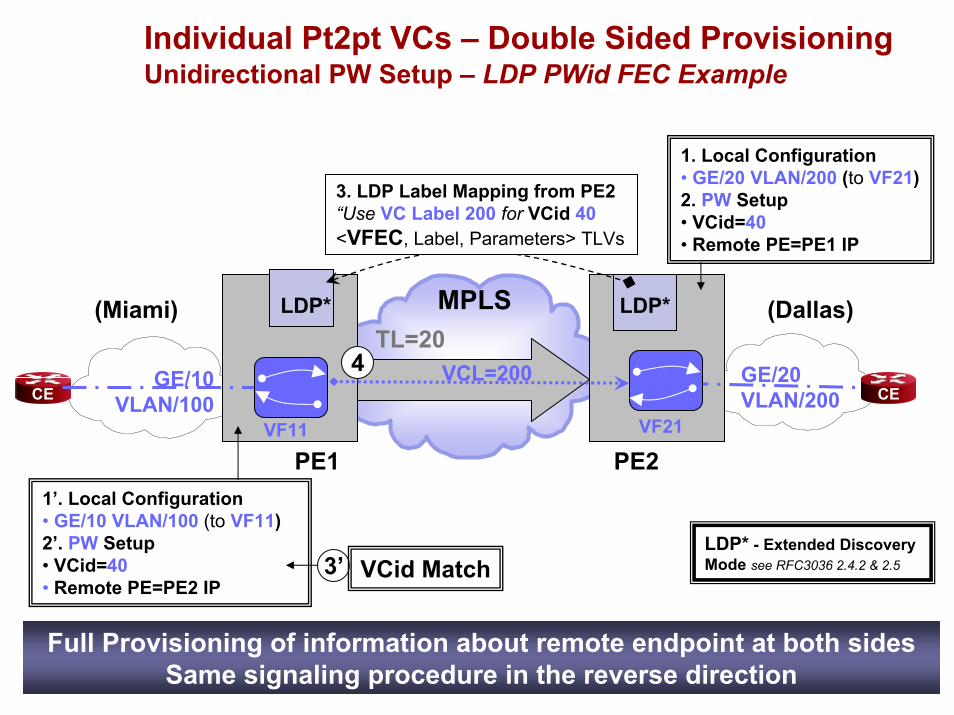
Individual Pt2pt VCs – Double Sided ProvisioningUnidirectional PW Setup – LDP PWid FEC Example
GE/10VLAN/100
MPLS
PE1
CE CE
LDP*
VCL=200
LDP*
VF11 (AI)
VF11 (AI)
VF21VF11
4
3. LDP Label Mapping from PE2 “Use VC Label 200 for VCid 40<VFEC, Label, Parameters> TLVs
1. Local Configuration • GE/20 VLAN/200 (to VF21)2. PW Setup• VCid=40• Remote PE=PE1 IP
TL=20GE/20 VLAN/200
(Miami) (Dallas)
PE21’. Local Configuration • GE/10 VLAN/100 (to VF11)2’. PW Setup• VCid=40• Remote PE=PE2 IP
LDP* - Extended Discovery Mode see RFC3036 2.4.2 & 2.53’ VCid Match
Full Provisioning of information about remote endpoint at both sidesSame signaling procedure in the reverse direction

PG 24Florin Balus & Mike Loomis NANOG30, Miami
Configuration Example 1 – Nortel PWEthernet PW – double-sided provisioning, PWid FEC
PE1 172.16.0.1
CE1
P P
CE2GE 1/0 GE 2/0
PE2 192.168.0.1(Miami)
p2p-vpn 40 Create { add-port 1/0 remote-peer 192.168.0.1
}
p2p-vpn 40 Create { add-port 2/0 remote-peer 172.16.0.1
}
(Dallas)
eth 1/0 { service-type l2unimode transparent
}
eth 2/0 {service-type l2unimode transparent
}
The focus of all the Examples in the package is on the L2VPN configuration. • Assumes “Backbone-facing” configuration is already in place: i.e. IP (interfaces, OSPF), MPLS (interfaces, LDP, Tunnel LSPs)

PG 25Florin Balus & Mike Loomis NANOG30, Miami
Configuration Example 2 – Cisco AToMFrame Relay PW – double-sided provisioning, PWid FEC
Interface Serial 1/0Encapsulation frame-relay ietfFrame-relay intf-type dce
!
102
connect frompls1 Serial1/0 100 l2transportxconnect 192.168.0.1 40 encapsulation mpls
100
PE1 172.16.0.1
CE1
P P
CE3
CE2S1/0 S2/0
PE2 192.168.0.1
(Miami)
connect frompls2 Serial2/0 102 l2transportxconnect 172.16.0.1 40 encapsulation mpls
(Dallas)
Interface Serial 2/0Encapsulation frame-relay ietfFrame-relay intf-type dce
!
PG 26Florin Balus & Mike Loomis NANOG30, Miami
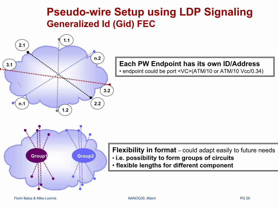
Pseudo-wire Setup using LDP Signaling Generalized Id (Gid) FEC
Each PW Endpoint has its own ID/Address• endpoint could be port <VC>(ATM/10 or ATM/10 Vcc/0.34)
1.12.1
3.1
n.1 2.2
3.2
n.2
1.2
Group1 Group2Flexibility in format – could adapt easily to future needs• i.e. possibility to form groups of circuits• flexible lengths for different component

PG 27Florin Balus & Mike Loomis NANOG30, Miami
Pseudo-wire Setup using LDP Signaling Generalized Id (Gid) FEC
(Dallas)
VF11 (AI)
VF(AI21)
CEGE/20VLAN/200
LDP
LDP Label Mapping <VFEC, Label, Parameters> TLVs
Gid tlv C Ethernet VC Info LengthSAII Length
Gid FEC
SAII = 20TAII Length
TAII = 10AGI Length
AGI = 11. Local Configuration • AC = GE/20 VLAN/200 to VF212. PW Setup• AI21 = <AGI = 1, SAII = 20>• Remote <AGI = 1, TAII = 10>• Remote PE = PE1
PE2
Each Virtual Forwarder uniquely Identified by "Attachment Identifier" (AI)• AI = <AGI (Attachment Group Identifier), AII (Attachment Individual Identifier)>• Concepts of Source AI (SAI – local VF) and Target AI (TAI – remote VF)
PW Signaling similar with the PWid FEC for Double-Sided Provisioning

PG 28Florin Balus & Mike Loomis NANOG30, Miami
Individual Pt2pt VCs - Single Sided Provisioning
Enterprise View SP Network CE2 CE1
PE2
MPLSVF11 (AI)
VF11 (AI)
PW Signaling
LDP LDP
Auto-discovery (optional)
A/D A/D
• AC = GE/20 VLAN/200 to VF21 • <AGI = 1, SAII = 20>• Remote <AGI = 1, TAII = 10>• Remote PE = PE1 ID
• AC = GE/10 VLAN/100 to VF1• <AGI = 1, SAII = 10>• Remote <AGI = 1, TAII =?>• Remote PE = ?
GE/10 VLAN/100
GE/20 VLAN/200
VCL=200
VCL=100
PE1(Miami) (Dallas)
No reconfiguration required when moving Attachment Circuit• compared with Double Sided Provisioning

PG 29Florin Balus & Mike Loomis NANOG30, Miami
Configuration Example 3- NortelEthernet PW – single-sided provisioning, Gid FEC
200 P
CE2GE 2/0
PE2 192.168.0.1 (Dallas)
100
PE1 172.16.0.1
CE1
P
GE 1/0
(Miami)
interface Eth 1/0 {unit 10 {
vlan-id 100vpws { }
} }
interface Eth 2/0 {unit 20 {
vlan-id 200vpws { }
} }
CE3
pseudo-wires {agi 1 {
sa 20200 {net-encapsulation ethernet-vlaninterface eth 2/0.20ta 10100 {
neighbor 172.16.0.1}
}}
}
pseudo-wires {agi 1 {
sa 10100 {net-encapsulation ethernet-vlaninterface eth 1/0.10
}}
}

PG 30Florin Balus & Mike Loomis NANOG30, Miami
Individual Point-to-point VCsExample of Data Forwarding – same for both models
Ethernet,VLANGE/10,VLAN/100
VC_Label200
Outer LSP
20 (TL to PE2)
Other PE1->PE2 PWssharing TL20
MPLS
PE2
CE CE
(Miami) (Dallas)
VF11 (AI)
VF11 (AI)
100
Ethernet,VLANGE/20,VLAN/200
VC_Label200
Outer LSPNULL (PHP)
200
TL=20
GE/10 VLAN/100
GE/20 VLAN/200
VCL=200TL=20
PE1
Simple VF: forwards data between 1 AC & 1 PW
PG 31Florin Balus & Mike Loomis NANOG30, Miami
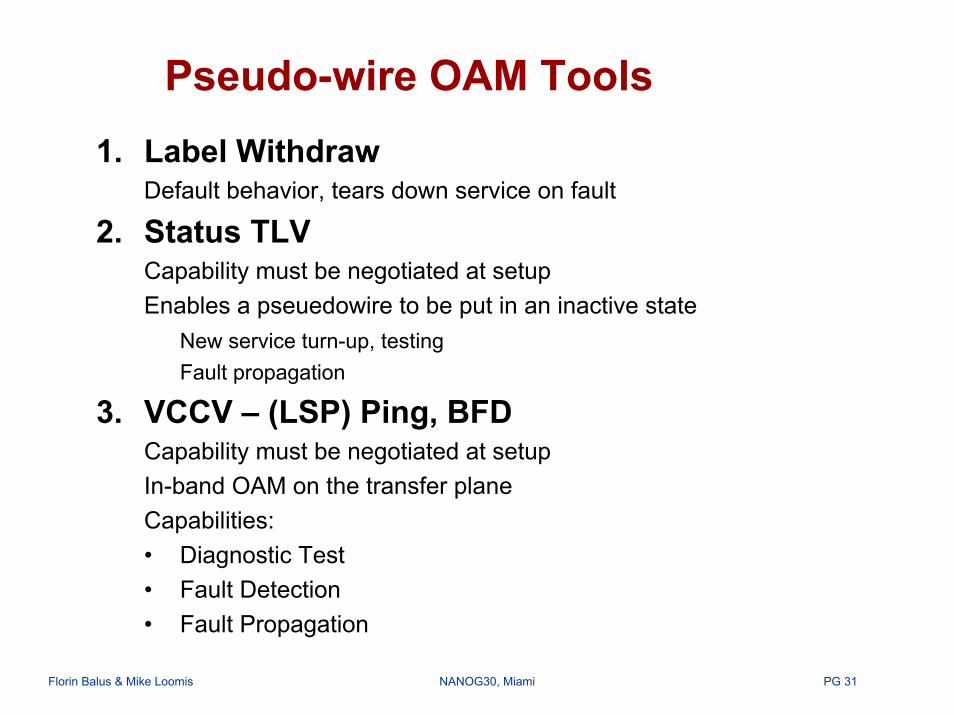
Pseudo-wire OAM Tools1. Label Withdraw
Default behavior, tears down service on fault
2. Status TLVCapability must be negotiated at setupEnables a pseuedowire to be put in an inactive state
New service turn-up, testingFault propagation
3. VCCV – (LSP) Ping, BFDCapability must be negotiated at setupIn-band OAM on the transfer plane Capabilities:• Diagnostic Test• Fault Detection• Fault Propagation

PG 32Florin Balus & Mike Loomis NANOG30, Miami
Example VCCV – Diagnostic TestSyntaxping pseudo-wire <count count | continuous> <pad pad-size> attachment-circuit
count count—(Optional) Number of ping requests to send. If count is not specified, 5 ping requests are sent.continuous—(Optional) Specifies that echo requests should be sent until the control-c character is received.pad pad-size—(Optional) Specifies the number of bytes to be appended to the LSP ping packets.attachment-circuit—Name of L2 attachment circuit from which to ping.
Sample OutputXXXX@node32> ping pseudo-wire eth 1/0 100Ping request for pseudo-wire started on 20-jan-03 23:10:10:
Remote PE Address: 192.168.0.1Source PE Address: 172.16.0.1Outgoing Service Label: 32Incoming Service Label: 100Outgoing Tunnel: 192.168.0.1/234PW Address: genid agi LNH, sa Miami, ta Dallas
23:10:10 86 byte echo reply received on fr-1/2:3.200: seq=1 time=0.456 ms23:10:11 86 byte echo reply received on fr-1/2:3.200: seq=2 time=0.656 ms23:10:12 86 byte echo reply received on fr-1/2:3.200: seq=3 time=0.556 ms23:10:13 86 byte echo reply received on fr-1/2:3.200: seq=4 time=0.466 ms23:10:14 86 byte echo reply received on fr-1/2:3.200: seq=5 time=0.490 ms--- pseudo-wire ping statistics ---5 packets transmitted, 5 packets received, 0% packet loss round-trip min/avg/max = 0.456/0.525/0.656 ms
PG 33Florin Balus & Mike Loomis NANOG30, Miami
VPWS Agenda
Provisioning Models - Individual Pt2pt Virtual CircuitsSolutions for Migrating Legacy L2 Services to MPLS
– Mediation to existing Layer 2 Services – Network Inter-working over MPLS– L2 Service Inter-working over MPLS

PG 34Florin Balus & Mike Loomis NANOG30, Miami
Dynamic Service Mediation with L2 servicesProblem Space
L2 EdgeL2PE
Protocol A - Signaling, Forwarding, OAM, TM : i.e. Native FR or ATM/PNNI Network Standards-based PWE3 - Signaling,
Forwarding, OAM, TM
MPLS CoreMPLS Edge
CE CE
PE
FR (ATM) Access
FR (ATM) Access
IWF
IWF
IWF
Dynamic mediation between the MPLS and the Layer 2 network• Enable dynamic Layer 2 call establishment end-to-end• Support resiliency under multiple failure conditions• Eliminate per call configuration at the Layer 2 mediation points

PG 35Florin Balus & Mike Loomis NANOG30, Miami
What is Network Inter-working?
• Inter-working required between networks of similar protocols across anintermediary/core network having a different protocol (e.g. MPLS transport between two ATM networks)
• Complete or part of the protocol control information used in the two similar networks are transferred transparently by an inter-working function (IWF) across the intermediary/core network
IWF
CE
A Z
CE
AIWF
Protocol A Protocol ATunnel Z
IWF encapsulates information

PG 36Florin Balus & Mike Loomis NANOG30, Miami
Network Inter-working over MPLSProblem Space
ATM/FR CE MPLS CE
Protocol A – Routing, Signaling, Forwarding,
OAM,TM L2 over MPLS - Routing, Signaling, PW Forwarding, OAM, TM
ATM/FR
Gateways
IWF IWF
IWF
Protocol A – Routing, Signaling, Forwarding,
OAM,TM
IWF
Gateways
Layer 2 Network Interworking over MPLS• Need scalable solution from both network & platform perspectives• Need to support existing service QOS• Should preserve existing Layer2 networking features
PG 37Florin Balus & Mike Loomis NANOG30, Miami
L2 Service Inter-working – General
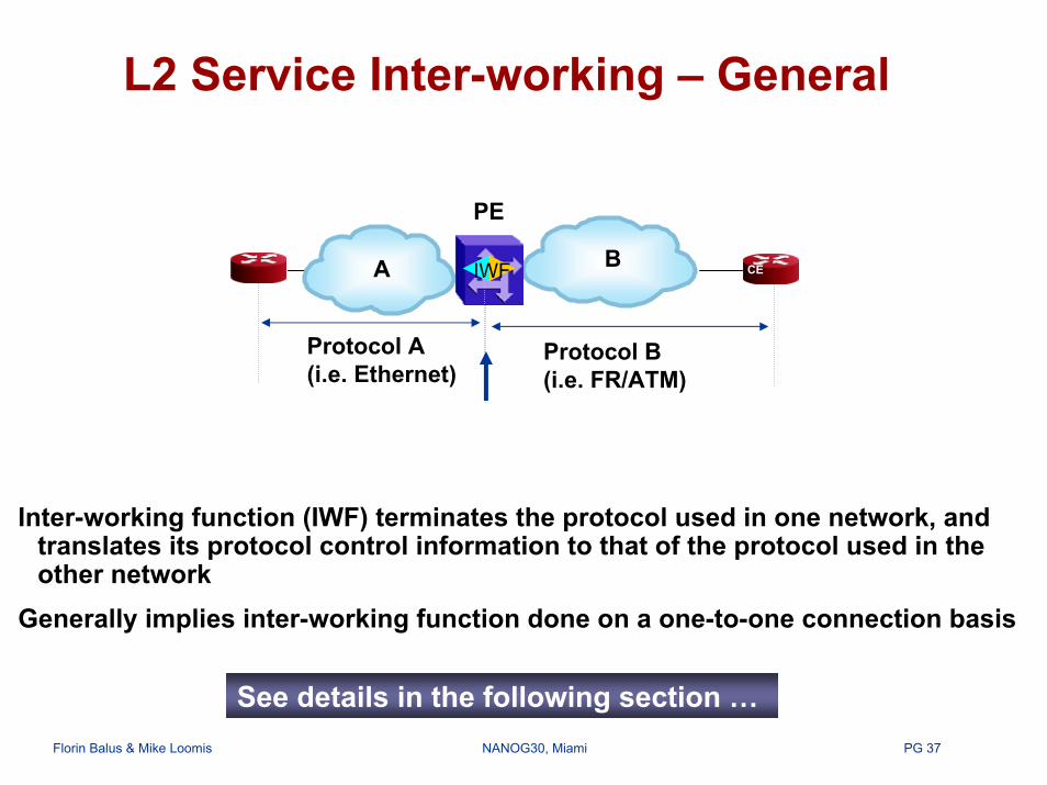
Inter-working function (IWF) terminates the protocol used in one network, and translates its protocol control information to that of the protocol used in the other network
Generally implies inter-working function done on a one-to-one connection basis
A CE BIWF
PE
CE
Protocol A(i.e. Ethernet)
Protocol B(i.e. FR/ATM)
See details in the following section …

PG 38Florin Balus & Mike Loomis NANOG30, Miami
Agenda
• Introduction to L2VPNs over MPLS• IETF Generic Models (L2VPNs)• Virtual Private Wire Service (VPWS)• Layer 2 Service Interworking• Virtual Private LAN Service (VPLS)• Summary

PG 39Florin Balus & Mike Loomis NANOG30, Miami
Pseudo-wire OptionsEthernet to ATM
IWF
Interworking Function
IWFIWF
EthernetFacing
ATM/FRFacing
Ethernet ATMLocal SwitchingVLAN PVC
PE
VLANMPLSPWE3 (Eth)
PE PE
VLANMPLSPWE3 (ATM)
PE PE
IWF
IWF
Ethernet ATMSingle Sided IWFMPLS Pseudo-wire
PVC
Ethernet ATMPVC
Distributed IWFIP over MPLS(routed mode only) VLAN
MPLSPWE3 (IP)
PE PE
IWFIWF
Ethernet ATMPVC
PG 40Florin Balus & Mike Loomis NANOG30, Miami
Frame RelayDLCI
IWF
Interworking Function
IWFIWF
EthernetFacing
ATM/FRFacing
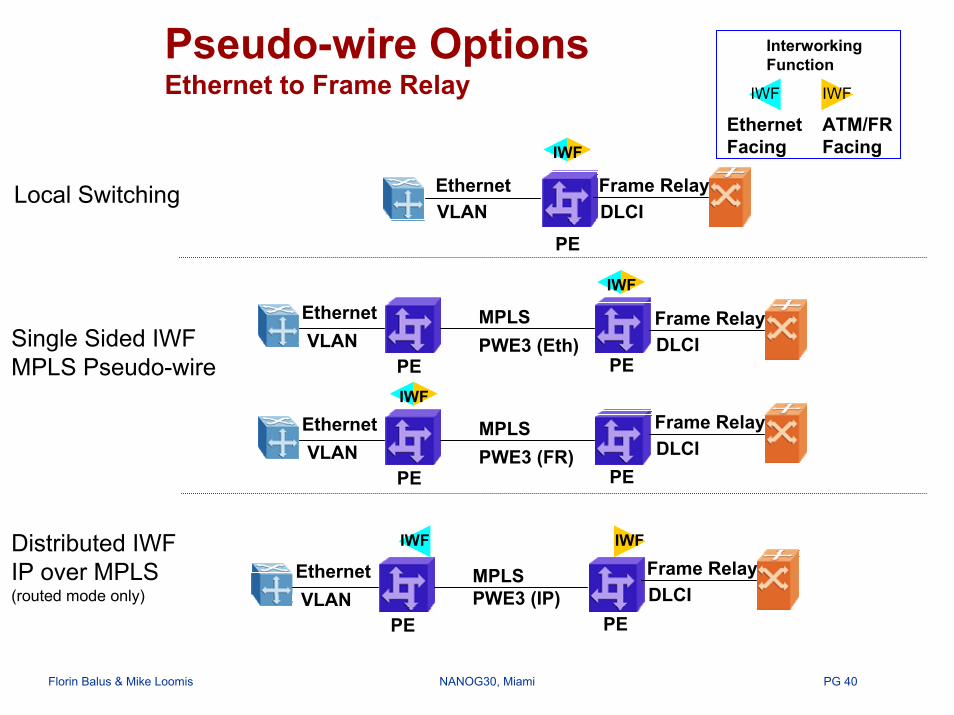
Pseudo-wire OptionsEthernet to Frame Relay
EthernetLocal SwitchingVLAN
PE
VLANMPLS
PE PE
VLANMPLS
PE PE
IWF
IWF
Frame RelayDLCI
Frame RelayDLCI
EthernetSingle Sided IWFMPLS Pseudo-wire
PWE3 (Eth)
Ethernet
PWE3 (FR)
Distributed IWFIP over MPLS(routed mode only) VLAN
MPLSPWE3 (IP)
PE PE
IWF IWF
Frame RelayDLCI
Ethernet

PG 41Florin Balus & Mike Loomis NANOG30, Miami
RFC 2684 (1483) Bridged ModePacket Walkthrough
EthernetVLAN
Ethernet
PE PE
MPLSPWE3 (Eth)
ATM
Customer PremiseCustomer
PremiseIWF
EthernetPVC
DataEthernet1483 BAAL5
DataEthernet
DataEthernetVC - EthMPLS TL
DataEthernet
DataEthernet
BroadcastDomain

PG 42Florin Balus & Mike Loomis NANOG30, Miami
RFC 2437 (1490) Bridged ModePacket Walkthrough
Customer Premise
Customer Premise
PE
Frame RelayDLCI
PE
EthernetVLAN
IWF
Ethernet EthernetMPLSPWE3 (Eth)
DataEthernet1490 BQ.922
DataEthernet
DataEthernetVC - EthMPLS TL
DataEthernet
DataEthernet
BroadcastDomain
PG 43Florin Balus & Mike Loomis NANOG30, Miami
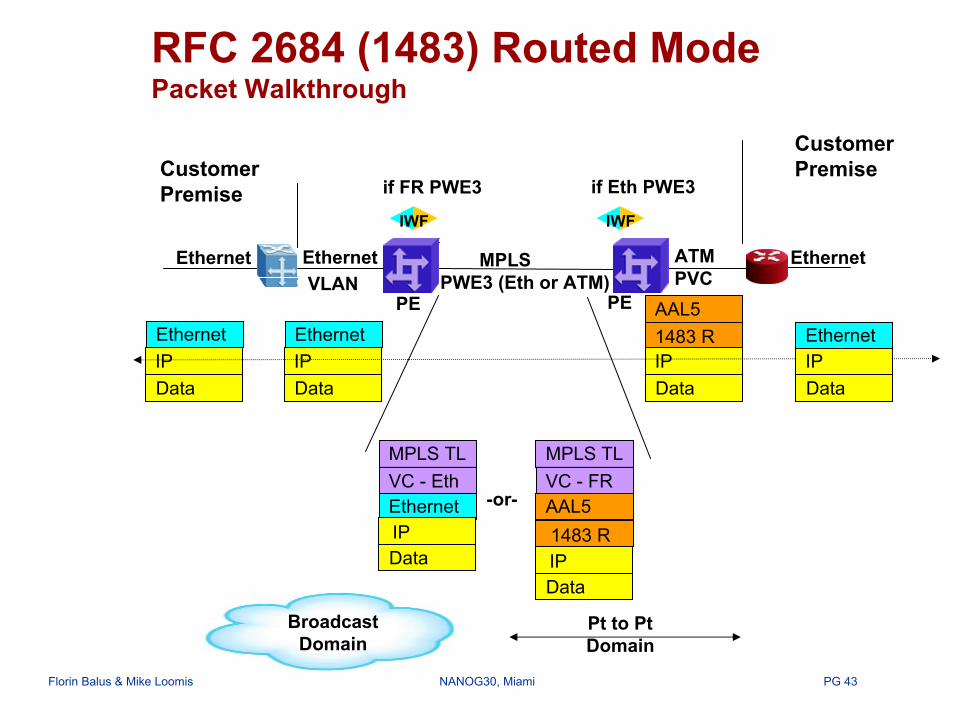
RFC 2684 (1483) Routed ModePacket Walkthrough
Customer Premise
EthernetVLAN
MPLSPWE3 (Eth or ATM)
Ethernet
EthernetVC - EthMPLS TL
1483 RAAL5
IPData
DataIP
AAL5VC - FRMPLS TL
DataIP
EthernetIPData
EthernetIPData
PE PE
BroadcastDomain
1483 R
IWFIWF
ATM
Customer Premise if Eth PWE3if FR PWE3
EthernetPVC
IPEthernet
Data
-or-
Pt to PtDomain

PG 44Florin Balus & Mike Loomis NANOG30, Miami
RFC 2437 (1490) Routed ModePacket Walkthrough
EthernetVLAN PWE3 (Eth or FR)
Frame RelayDLCI
Ethernet
Customer Premise
Ethernet
EthernetVC - EthMPLS TL
IPEthernet
Data
1490 RQ.922
IPData
DataIP
Q.922VC - FRMPLS TL
DataIP
EthernetIPData
EthernetIPData
if Eth PWE3
PE PE
BroadcastDomain
1490 R
IWFIWF
Customer Premise if FR PWE3
MPLS
-or-
Pt to PtDomain

PG 45Florin Balus & Mike Loomis NANOG30, Miami
Routed InterworkingPE Device
Ethernet FacingInterworking Function
ATM/FR FacingInterworking Function
IP: 192.168.1.2
PE
CE B
Loopback IP: 47.55.44.1
CE A
IP: 192.168.1.1MAC: aa:aa:aa:aa:aa:aa
MAC: bb:bb:bb:bb:bb:bb
IP HeaderQ.922 | 1490RIP Headeraa:aa|bb:bb| Etype | Q-Tag
• Remove ATM/FR Data link header• Add Ethernet Data link header
Source MAC = PE interface MACDestination MAC = Eth CE Interface MAC
PE (Eth IWF) must know the hardware address of CE A

PG 46Florin Balus & Mike Loomis NANOG30, Miami
Routed InterworkingCE Device
Ethernet FacingInterworking Function
ATM/FR FacingInterworking Function
IP: 192.168.1.2
PE
CE B
Loopback IP: 47.55.44.1
CE A
IP: 192.168.1.1MAC: aa:aa:aa:aa:aa:aa
MAC: bb:bb:bb:bb:bb:bb
IP Headerbb:bb|aa:aa | Etype | Q-Tag IP HeaderQ.922 | 1490R
CE send packets destined for next hop = CE B (192.168.1.2) to hardware address bb:bb:bb:bb:bb:bb
IWF forwards all IP packets received on interworking interface (port, VID) to appropriate PVC
CE A must have Eth IWF hardware address for next hop = CE B
PG 47Florin Balus & Mike Loomis NANOG30, Miami
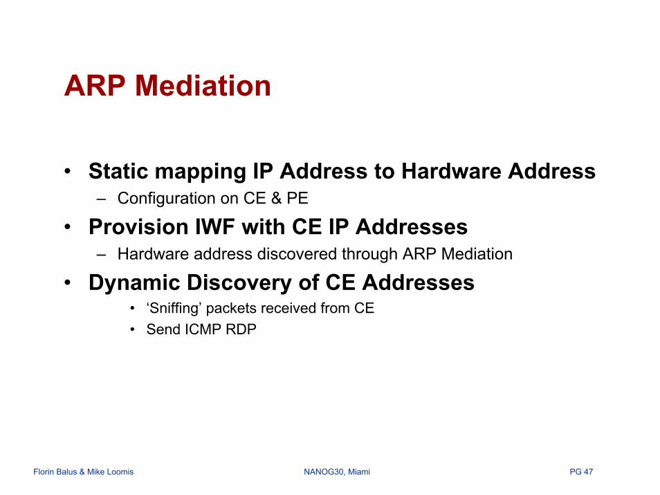
ARP Mediation
• Static mapping IP Address to Hardware Address– Configuration on CE & PE
• Provision IWF with CE IP Addresses– Hardware address discovered through ARP Mediation
• Dynamic Discovery of CE Addresses• ‘Sniffing’ packets received from CE• Send ICMP RDP
PG 48Florin Balus & Mike Loomis NANOG30, Miami
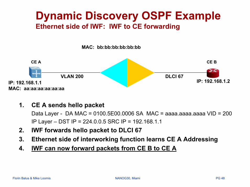
Dynamic Discovery OSPF ExampleEthernet side of IWF: IWF to CE forwarding
MAC: bb:bb:bb:bb:bb:bb
1. CE A sends hello packetData Layer - DA MAC = 0100.5E00.0006 SA MAC = aaaa.aaaa.aaaa VID = 200IP Layer – DST IP = 224.0.0.5 SRC IP = 192.168.1.1
2. IWF forwards hello packet to DLCI 673. Ethernet side of interworking function learns CE A Addressing4. IWF can now forward packets from CE B to CE A
IP: 192.168.1.2
CE A CE B
IP: 192.168.1.1MAC: aa:aa:aa:aa:aa:aa
VLAN 200 DLCI 67

PG 49Florin Balus & Mike Loomis NANOG30, Miami
Dynamic Discovery OSPF ExampleEthernet side of IWF: CE to IWF forwarding
MAC: bb:bb:bb:bb:bb:bb
1. CE A sends ARP request on VLAN 200 for Next hop IP address2. IWF sends ARP reply with MAC = bb:bb:bb:bb:bb:bb3. CE A can now forward packets to CE B
NOTE – interworking circuit must be point to point and contain only 2 customer routers
CE A CE B
IP: 192.168.1.1MAC: aa:aa:aa:aa:aa:aa
VLAN 200 DLCI 67IP: 192.168.1.2

PG 50Florin Balus & Mike Loomis NANOG30, Miami
Dynamic Discovery OSPF ExampleFR side of IWF
MAC: bb:bb:bb:bb:bb:bb
Interworking function remove/apply data link layer header
IWF can respond to invARP from CE B
NOTE – interworking circuit must be point to point and contain only 2 customer routers.
IP: 192.168.1.2
CE A CE B
IP: 192.168.1.1MAC: aa:aa:aa:aa:aa:aa
VLAN 200 DLCI 67

PG 51Florin Balus & Mike Loomis NANOG30, Miami
ARP MediationSingle Sided Solution
Customer Premise
Customer Premise
CE A CE BEthernetVLAN PWE3 (Ethernet)
Ethernet Frame Relay EthernetMPLSDLCI
PE1 PE2
IWF responds ARP request with MAC of interworking function
ARP RequestIWFARP Reply
ARP RequestIWF sends ARP request for IP of CE A to learn CE A MACARP Reply

PG 52Florin Balus & Mike Loomis NANOG30, Miami
ARP MediationDouble Sided Solution
Customer Premise
Customer Premise
CE A CE B
ARP RequestARP Reply
PE1 PE2
IWF IWF
IWF responds ARP request with MAC of interworking function
ARP Request IWF sends ARP request for IP of CE A to learn CE A MACARP Reply
EthernetVLAN
Ethernet Frame Relay EthernetMPLSPWE3 (IP) DLCI

PG 53Florin Balus & Mike Loomis NANOG30, Miami
Multiservice Interworking OAM Reference Model
PE 1 PE 2
NativeService
OAM
NSP PWE PWE NSP
NativeService
B
NativeService
A PSN Tunnel
Pseudo-wireAttachment
CircuitAttachment
CircuitCE 1 CE 2
NativeService
OAMPWE3 OAM
PSN OAM
PG 54Florin Balus & Mike Loomis NANOG30, Miami
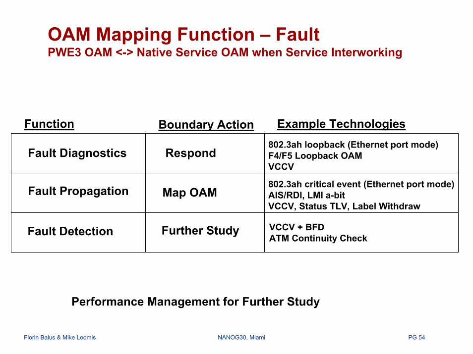
OAM Mapping Function – FaultPWE3 OAM <-> Native Service OAM when Service Interworking
Example TechnologiesFunction Boundary Action
Fault Diagnostics Respond802.3ah loopback (Ethernet port mode)F4/F5 Loopback OAMVCCV
Fault Propagation Map OAM802.3ah critical event (Ethernet port mode)AIS/RDI, LMI a-bitVCCV, Status TLV, Label Withdraw
Fault Detection Further Study VCCV + BFDATM Continuity Check
Performance Management for Further Study

PG 55Florin Balus & Mike Loomis NANOG30, Miami
fe-1/0/0bb:bb:bb:bb:bb:b
CE1 CE21.1.1.2cc:cc:cc:cc:cc:cc
Static ARP entryarp 1.1.1.1
bb:bb:bb:bb:bb:bb
interfaces {fe-1/0/0 {
encapsulation ethernet-tccunit 0 {
family tcc {remote {
mac-address cc:cc:cc:cc:cc:cc}
}}
}}
interfaces {so-1/0/0 {
dce;encapsulation frame-relay-tcc
unit 750 {point-to-point;encapsulation frame-relay-tccdlci 750
}}
}
protocols {mpls{
interface so-1/0/0.750interface fe-1/0/0.0
}connections {
interface-switch FR-to-Ether {interface so-1/0/0.750
interface fe-1/0/0.0}
}}
Configuration Example 4 – Juniper TCC L2 Interworking - Routed Mode
PE1
1.1.1.1DCLI 750 so-1/0/0

PG 56Florin Balus & Mike Loomis NANOG30, Miami
Configuration Example 5 - NortelFR-Ethernet Interworking – Routed Mode with ARP Mediation
200100
PE1 172.16.0.1
CE1
P P
CE2GE 1/0 FR 2/0
PE2 192.168.0.1
FR 2/0 {unit 20 {
dlci 200vpws { }
}}
(Miami) (Dallas)
Frame Relay PWinterface Eth 1/0 {
unit 10 {vlan-id 100vpws {
interworking ipdiscovery { }
}}
}pseudo-wires {
agi 1 { sa 10100 {
net-encapsulation fr-dlciinterface eth 1/0.10ta 20200 {
neighbor 192.168.0.1}
}}
}
pseudo-wires {agi 1 {
sa 20200 {net-encapsulation fr-dlciinterface fr 2/0.20
}}
}

PG 57Florin Balus & Mike Loomis NANOG30, Miami
Agenda
• Introduction to L2VPNs over MPLS• IETF Generic Models (L2VPNs)• Virtual Private Wire Service (VPWS)• Layer 2 Service Interworking• Virtual Private LAN Service (VPLS)• Summary

PG 58Florin Balus & Mike Loomis NANOG30, Miami
Virtual Private LAN Service (VPLS)Service Provider View
CE
PE
P P
MPLS Core
PE
PE
CE
CE
CE
CE
VF
VF
VF
Logical Bridge
Enterprise ViewPE
P P
MPLS Core
PE
PECE
CE
CE
CE
CE
PG 59Florin Balus & Mike Loomis NANOG30, Miami
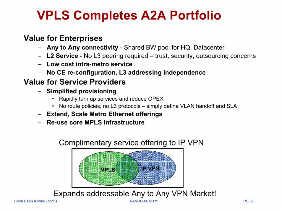
VPLS Completes A2A PortfolioValue for Enterprises
– Any to Any connectivity - Shared BW pool for HQ, Datacenter– L2 Service - No L3 peering required – trust, security, outsourcing concerns– Low cost intra-metro service– No CE re-configuration, L3 addressing independence
Value for Service Providers– Simplified provisioning
• Rapidly turn up services and reduce OPEX• No route policies, no L3 protocols – simply define VLAN handoff and SLA
– Extend, Scale Metro Ethernet offerings– Re-use core MPLS infrastructure
IP VPNVPLS
Expands addressable Any to Any VPN Market!
Complimentary service offering to IP VPN

PG 60Florin Balus & Mike Loomis NANOG30, Miami
VPLS – Control & Data Plane Components
IP Domain (MPLS)
AC
(Miami 1)
PE2
(Miami 2)
PE3
A/DA/D
A/D
A/D
VSI11
PWPW
PW
AC
AC
AC
AC
Sign
Sign Sign
(Dallas)
(Miami 3)VSI31
VSI21
PE4
PE1
• A/D = Auto-discovery of PEs that contain at least one site in Blue VPN• Sign = PW Signaling – should link all the Blue VSIs via a full mesh of PWs• Virtual Forwarder called Virtual Switched Instance (VSI)
PG 61Florin Balus & Mike Loomis NANOG30, Miami
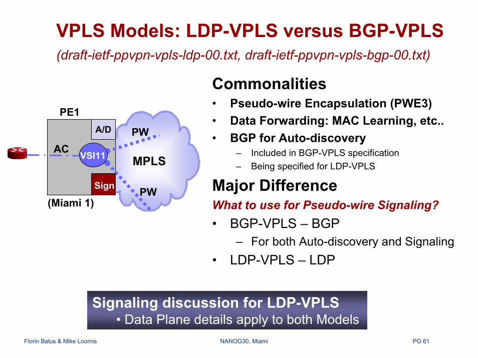
VPLS Models: LDP-VPLS versus BGP-VPLS (draft-ietf-ppvpn-vpls-ldp-00.txt, draft-ietf-ppvpn-vpls-bgp-00.txt)
MPLS
A/D
VSI11
PW
PW
Sign
Commonalities• Pseudo-wire Encapsulation (PWE3)• Data Forwarding: MAC Learning, etc..• BGP for Auto-discovery
– Included in BGP-VPLS specification– Being specified for LDP-VPLS
Major DifferenceWhat to use for Pseudo-wire Signaling?• BGP-VPLS – BGP
– For both Auto-discovery and Signaling• LDP-VPLS – LDP
AC
PE1
(Miami 1)
Signaling discussion for LDP-VPLS• Data Plane details apply to both Models

PG 62Florin Balus & Mike Loomis NANOG30, Miami
VPLS Information ModelGeneral Addressing Philosophy
PE2
PE3ACs
AC
AC
AC
(Dallas)
(Miami 3)
VSI21
Each VPLS has a Globally Unique
Identifier say “Blue”Config(VSI21)1. VPNid= “Blue”
….
Config(VSI11)1. VPNid= “Blue”
….
VSI11
VSI31
ACMPLS
PE4
(Miami 1) (Miami 2)PE1
Config(VSI31)1. VPNid= “Blue”
….
PW Endpoint uniquely identified by <PE IP, VPNid>• I need to interconnect through signaling just the VSIs not the ACs• Full Mesh of PWs – no variations in topology

PG 63Florin Balus & Mike Loomis NANOG30, Miami
VPLS Information Model Configuring a new VSI on PE1
Config(VSI21):• VPNid= “Blue”• Local ACs
A/D or Configuration Blue VPN• PE2
A/D or Configuration Blue VPN• PE3
PE2
PE3AC
AC
AC
AC
(Dallas)
VSI21
VSI31
PWConfig(VSI11):1. VPNid= “Blue”2. Provision 1st AC
VSI11 CE1
1st Site in PE1
AC
3. A/D or Configuration Blue VPN-Remote PEs• PE1, PE3
3. A/D or ConfigurationBlue VPN-Remote PEs• PE1, PE2
Config(VSI31):• VPNid= “Blue”• Local ACs
MPLS
PE4(Miami 1) (Miami 2)PE1
3. A/D or ConfigurationBlue VPN-Remote PEs• PE2, PE3
(Miami 3)
List of (related) Remote PEs could be generated by an A/D process (BGP)• Current LDP-VPLS draft - Manual Configuration
PG 64Florin Balus & Mike Loomis NANOG30, Miami
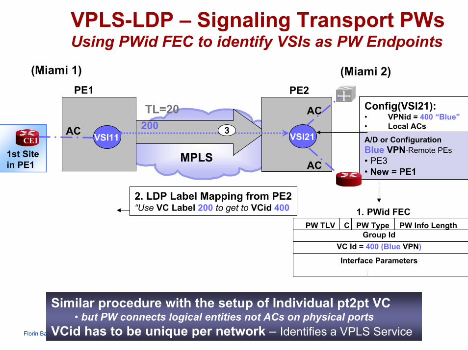
VPLS-LDP – Signaling Transport PWsUsing PWid FEC to identify VSIs as PW Endpoints
(Miami 1) (Miami 2)
TL=20
MPLS
VSI11 CE1
1st Site in PE1
ACA/D or ConfigurationBlue VPN-Remote PEs• PE3• New = PE1AC
AC
VSI21
2. LDP Label Mapping from PE2 “Use VC Label 200 to get to VCid 400
PW TLV C PW Type PW Info LengthGroup Id
VC Id = 400 (Blue VPN)
Interface Parameters
1. PWid FEC
3200
PE1 PE2Config(VSI21):• VPNid = 400 “Blue”• Local ACs
Similar procedure with the setup of Individual pt2pt VC• but PW connects logical entities not ACs on physical ports
VCid has to be unique per network – Identifies a VPLS Service

PG 65Florin Balus & Mike Loomis NANOG30, Miami
VPLS Data Plane – High Level View
AC
PE2
(Miami 2)
PE3
PWPW
PW
AC
AC
AC
AC
(Dallas)
Avoid Spanning Tree• Full Mesh PW• Split Horizon
VSI11
VSI31
VSI21
PE4
PE1
(Miami 1)
(Miami 3)Let’s zoom inside PE3
Split Horizon explained in the next slide
PG 66Florin Balus & Mike Loomis NANOG30, Miami
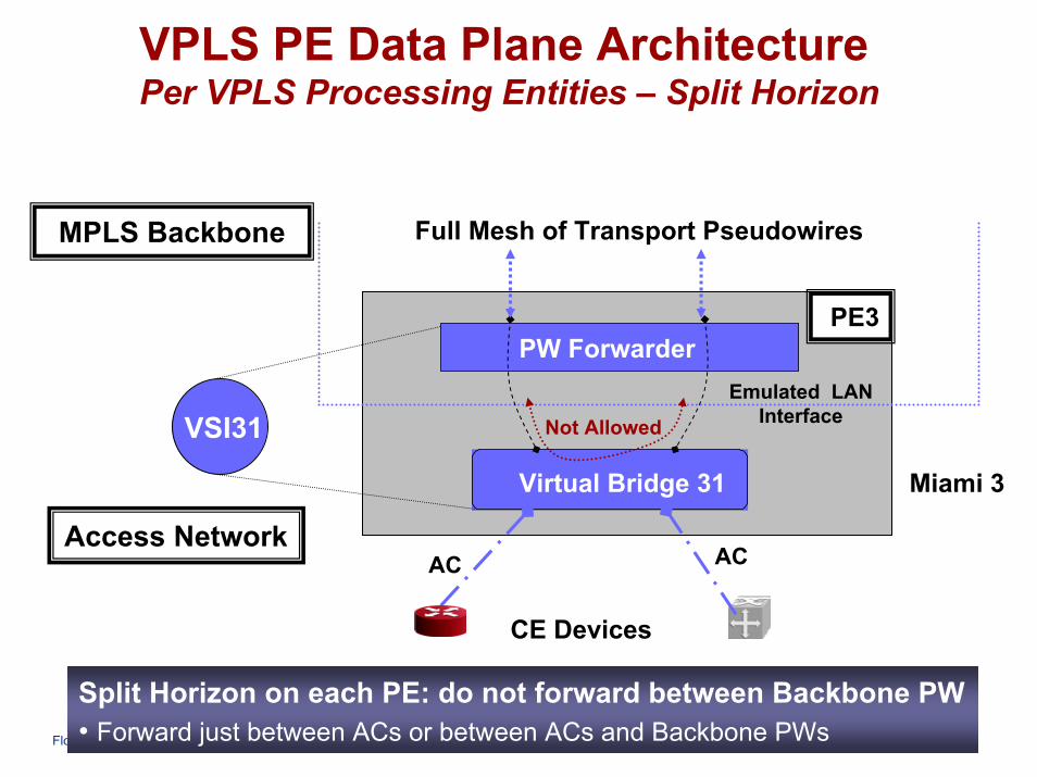
VPLS PE Data Plane ArchitecturePer VPLS Processing Entities – Split Horizon
PW Forwarder
Virtual Bridge 31
CE Devices
Emulated LAN Interface
PE3
AC AC
VSI31 Not Allowed
MPLS Backbone Full Mesh of Transport Pseudowires
Miami 3
Access Network
Split Horizon on each PE: do not forward between Backbone PW• Forward just between ACs or between ACs and Backbone PWs

PG 67Florin Balus & Mike Loomis NANOG30, Miami
VPLS Data Plane – Packet WalkthroughBroadcast, Mcast Frames
PE1 PE2
(Miami 2)
PE4
PE3
PWPW
PW
AC
AC
ACy
AC
(Dallas)
VSI11
VSI31
VSI21
1. Broadcast Packet from
MAC X
XB
2. FDB: X-ACx
3. FDB: X-PWa
3. FDB: X-PWb
ACxMAC X
(Miami 1)
(Miami 3)
Frames Broadcasted through the Provider Network• to any PE with at least one site in Blue VPN, replicated as needed

PG 68Florin Balus & Mike Loomis NANOG30, Miami
VPLS Data Plane – Packet WalkthroughUnicast Frame – Broadcast Phase
PE1 PE2
(Miami 2)
PE4
PE3
PWa
PWb
AC
AC
AC
AC
(Dallas)
(Miami 3)
VSI11
VSI31
VSI21
MAC Y
2. Don’t have MAC Y in FDB
2. FDB: X-ACx
3. FDB: X-PWa
3. FDB: X-PWb
3. Don’t have MAC Y in FDB
3. Don’t have MAC Y in FDB
1. Packet from MAC
X->Y
XY
ACxMAC X
(Miami 1)
Frames Broadcasted through the Provider Network• to any PE with at least one site in Blue VPN, replicated as needed

PG 69Florin Balus & Mike Loomis NANOG30, Miami
VPLS Data Plane – Packet WalkthroughUnicast Frame – Unicast Phase
ACx
PE1
(Miami 1)
PE2
(Miami 2)
PE4
PE3
PWa
PWb
AC
AC
ACy
AC
(Dallas)
(Miami 3)
VSI11
VSI31
VSI21
XY
1. Packet from MAC
Y->X
FDB: X-PWb
XY
FDB: X-PWaFDB: X-PWa2. Y-ACy
FDB: X-ACxFDB: X-ACx3. Y-PWa
MAC X
MAC Y
Unicast in the reverse direction is unicasted through SP Backbone• in the same time PE2 and then PE1 learn the location of MAC Y
PG 70Florin Balus & Mike Loomis NANOG30, Miami
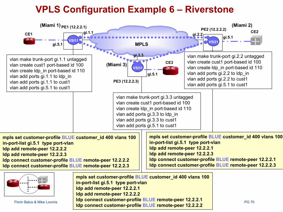
VPLS Configuration Example 6 – Riverstone
(Miami 3)
VSI11 VSI21
VSI31
gi.1.1
MPLS
gi.2.2
gi.3.3
gi.5.1
CE3vlan make trunk-port gi.1.1 untaggedvlan create cust1 port-based id 100vlan create ldp_in port-based id 110vlan add ports gi.1.1 to ldp_invlan add ports gi.1.1 to cust1vlan add ports gi.5.1 to cust1
mpls set customer-profile BLUE customer_id 400 vlans 100 in-port-list gi.5.1 type port-vlanldp add remote-peer 12.2.2.2ldp add remote-peer 12.2.2.3ldp connect customer-profile BLUE remote-peer 12.2.2.2ldp connect customer-profile BLUE remote-peer 12.2.2.3
vlan make trunk-port gi.3.3 untaggedvlan create cust1 port-based id 100vlan create ldp_in port-based id 110vlan add ports gi.3.3 to ldp_invlan add povlan add po
vlan make trunk-port gi.2.2 untaggedvlan create cust1 port-based id 100vlan create ldp_in port-based id 110vlan add ports gi.2.2 to ldp_invlan add ports gi.2.2 to cust1vlan add ports gi.5.1 to cust1
mpls set customer-profile BLUE customer_id 400 vlans 100 in-port-list gi.5.1 type port-vlanldp add remote-peer 12.2.2.1ldp add remote-peer 12.2.2.3ldp connect customer-profile BLUE remote-peer 12.2.2.1ldp connect customer-profile BLUE remote-peer 12.2.2.3
PE2 (12.2.2.2)
PE3 (12.2.2.3)
(Miami 1) (Miami 2)PE1 (12.2.2.1)CE2CE1
gi.5.1
gi.5.1
rts gi.3.3 to cust1rts gi.5.1 to cust1
mpls set customer-profile BLUE customer_id 400 vlans 100 in-port-list gi.5.1 type port-vlanldp add remote-peer 12.2.2.1ldp add remote-peer 12.2.2.2ldp connect customer-profile BLUE remote-peer 12.2.2.1ldp connect customer-profile BLUE remote-peer 12.2.2.2

PG 71Florin Balus & Mike Loomis NANOG30, Miami
VPLS Decoupled Model - Configuration Example 7 Nortel
VSI11 eth 1./1MPLS eth 2/1
N-PE2 (12.2.2.2)
N-PE3 (12.2.2.3)
VSI31
U-PE11 10.0.11.2
VSI21
U-PE21 10.0.21.2
U-PE31
eth 3/1
vpls-vpn 2001 { add remote-peer 12.2.2.2 tunnel 12add remote-peer 12.2.2.3 tunnel 13
}
td 2001 create name VPN2001adm enableeth 1 UNI ID 0.0.11.1eth 1 type transparenteth 1 transparent 2001
eth 1/1 { service-type vpls
}
eth 1 eth 1
vpls-vpn 2001 { add remote-peer 12.2.2.1 tunnel 21add remote-peer 12.2.2.3 tunnel 23
}
eth 2/1 { service-type vpls
}
td 2001 create name VPN2001adm enableeth 1 UNI ID 0.0.11.2eth 1 type transparenteth 1 transparent 2001
vpls-vpn 2001 { add remote-peer 12.2.2.1 tunnel 21add remote-peer 12.2.2.3 tunnel 23
}
eth 2/1 { service-type vpls
}
N-PE1 (12.2.2.1)
CE2CE1
CE3
td 2001 create name VPN2001adm enableeth 1 UNI ID 0.0.11.3eth 1 type transparenteth 1 transparent 2001
PG 72Florin Balus & Mike Loomis NANOG30, Miami
Agenda
• Introduction to L2VPNs over MPLS• IETF Generic Models (L2VPNs)• Virtual Private Wire Service (VPWS)• Virtual Private LAN Service (VPLS)• Layer 2 Interworking• Summary

PG 73Florin Balus & Mike Loomis NANOG30, Miami
Summary
Common Building Blocks for All L2VPNs• Information Model/Provisioning, Auto-discovery, Signaling, Data Plane
Auto-discovery - BGP seems the mechanism of choicePW Signaling - Contention Point between BGP, LDP: LDP seems to prevail• LDP Implementations announced by most of the Vendors• Gid FEC (LDP) to be used where more addressing flexibility, functionality is requiredData Plane Encapsulation – “PWE3-style”• Proved Interoperability of Layer 2 Point-to-point service over MPLS
Status of different Information Models/Services presented• Individual Pt2pt VCs
– Double-Sided Provisioning - Interoperable Implementations, some deployment– Single-Sided Provisioning – Interesting applicability for Migrating L2 Legacy…
• Migrating Legacy L2 Services to MPLS – Possibly the Next Big Tide• VPLS – New service type, complementing existing service types (i.e. pt2pt, IPVPNs)

PG 74Florin Balus & Mike Loomis NANOG30, Miami
References
Suggested reading - IETF DraftsAuto-discovery – draft-ietf-ppvpn-bgpvpn-auto-05.txt
Signaling - draft-ietf-l2vpn-signaling-00.txt, draft-ietf-pwe3-control-protocol-03.txt
Data Plane Encapsulation - draft-ietf-pwe3-<protocol>-encap-xx.txt
• i.e. for Ethernet would be draft-ietf-pwe3-ethernet-encap-03.txt
Information Models - draft-ietf-l2vpn-signaling-00.txt
Solutions• draft-ietf-ppvpn-vpls-ldp-00.txt, draft-ietf-ppvpn-vpls-bgp-00.txt
Email: [email protected]@nortelnetworks.com