(mpls) and traditional networks core protocols
TRANSCRIPT

1
Sudan Engineering Society Journal, September 2014, Volume 60; No.2
COMPARISON BETWEEN NGN CORE NETWORKS PROTOCOL (MPLS) AND
TRADITIONAL NETWORKS CORE PROTOCOLS (RIP & OSPF) USING OPNET
Amir Ahmed Omer Yousif, Sami M. Sharif and Hamid Abbas Ali Electrical and Electronic Engineering Department, Faculty of Engineering, University of Khartoum
E-mail: [email protected]
Received July 2014, accepted after revision Sep. 2014
مـســتخـلـص
انشبكاث انتى تقو ف links utilizationانتصالث إستغالنت أساط عهى يقاست دساست انسق ز تقذو
Open Shortest (OSPF) ، بشتكلRIP Routing information Protocol)) بتشغم بشتكل
Path First بشتكل ((MPLS Multi-Protocol Label Switching. نحظ ضعف إستغالنت قذ
نشبكت يحاكاة يفصهت تى اخشاء دساست. RIP OSPF استخذاو حانت ف links utilizationانتصالث
MPLS أظشث انذساست ا شبكت حثMPLS تقهم االصدحاو تدب يا ؤدي انى انشابط يعظى تستغم
.صفف طهباث انخذي
تى . تحهها انشبكاث نتصى خصصا انضي انحقق يصىبشايح يحاكاة ف OPNETبشايح انـ
تك نب اي شبكت ي عذد ي ب نب انشبكاث انقذ انحذث. ا نهقاست OPNET إستخذاو يحاك
(FTP) انهفاث قم تى استخذاو بشتكل. (IP and MPLS )( ف حانت كم ي (routersانخاث
انتحهه.ف زا انرج انصث
Abstract
This paper presents comparison study based on link utilization in the networks
running over Routing information Protocol (RIP), Open Shortest Path First (OSPF) and
Multi-Protocol Label Switching (MPLS). Poor link utilization in case of RIP and OSPF is
identified. A detailed simulation study is performed over MPLS network where we
have shown MPLS network has utilized most of links resulting in congestion
avoidance and low queuing delay.
OPNET is a real time simulator specifically designed for network design and analysis.
OPNET Simulator is used here to compare the networks cores. The core of a network
consists of a number of routers in each of the two cases (IP and MPLS). FTP and
VOICE traffic were used in this simulation model.
Keywords: MPLS, RIP, OSPF, Link Utilization, Traffic Engineering, OPNET.
1 INTRODUCTION
OPNET is a real time simulator specifically
designed for network design and analysis.
OPNET simulator is used here to compare
the networks cores. The core of a network
consists of a number of routers in each of
the two cases (IP and MPLS). Three types of
traffic: FTP, VOICE and VIDEO are used on
client sides with three corresponding
servers on the receiving end.
This paper presents a comparison study
between NGN networks core protocol
(MPLS) and traditional networks core
protocols (RIP & OSPF) using OPNET. It will
cover the fundamental concepts of all
important areas of NGNs, such as network
evolution, convergence, fixed-mobile
2 Sudan Engineering Society Journal, September 2014, Volume 60; No.2
COMPARISON BETWEEN NGN CORE NETWORKS PROTOCOL (MPLS) AND TRADITIONAL NETWORKS CORE PROTOCOLS (RIP & OSPF) USING OPNET
convergence, NGN definition,
characteristics, architecture, migration,
regulation, and standards, as well as case
studies and experimental works in NGN.
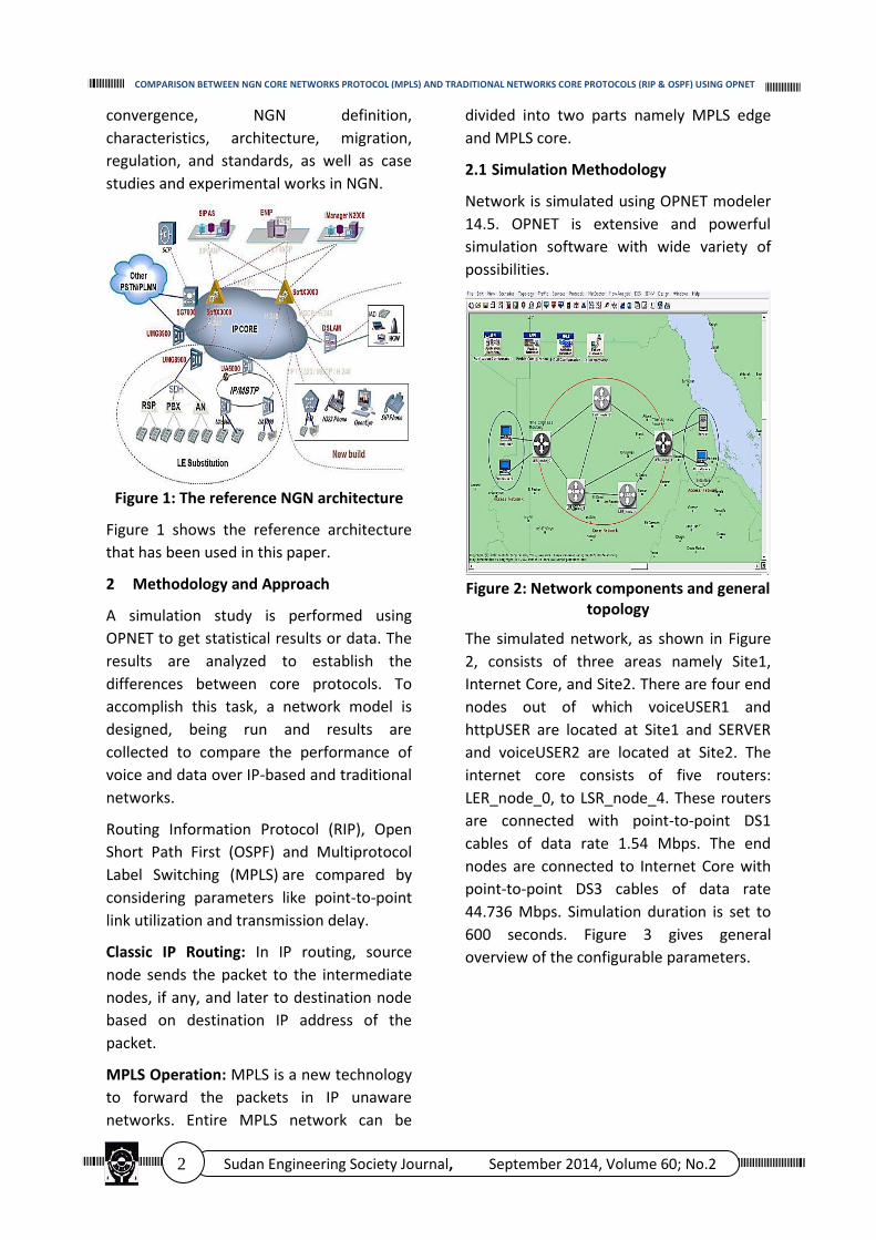
Figure 1: The reference NGN architecture
Figure 1 shows the reference architecture
that has been used in this paper.
2 Methodology and Approach
A simulation study is performed using
OPNET to get statistical results or data. The
results are analyzed to establish the
differences between core protocols. To
accomplish this task, a network model is
designed, being run and results are
collected to compare the performance of
voice and data over IP-based and traditional
networks.
Routing Information Protocol (RIP), Open
Short Path First (OSPF) and Multiprotocol
Label Switching (MPLS) are compared by
considering parameters like point-to-point
link utilization and transmission delay.
Classic IP Routing: In IP routing, source
node sends the packet to the intermediate
nodes, if any, and later to destination node
based on destination IP address of the
packet.
MPLS Operation: MPLS is a new technology
to forward the packets in IP unaware
networks. Entire MPLS network can be
divided into two parts namely MPLS edge
and MPLS core.
2.1 Simulation Methodology
Network is simulated using OPNET modeler
14.5. OPNET is extensive and powerful
simulation software with wide variety of
possibilities.
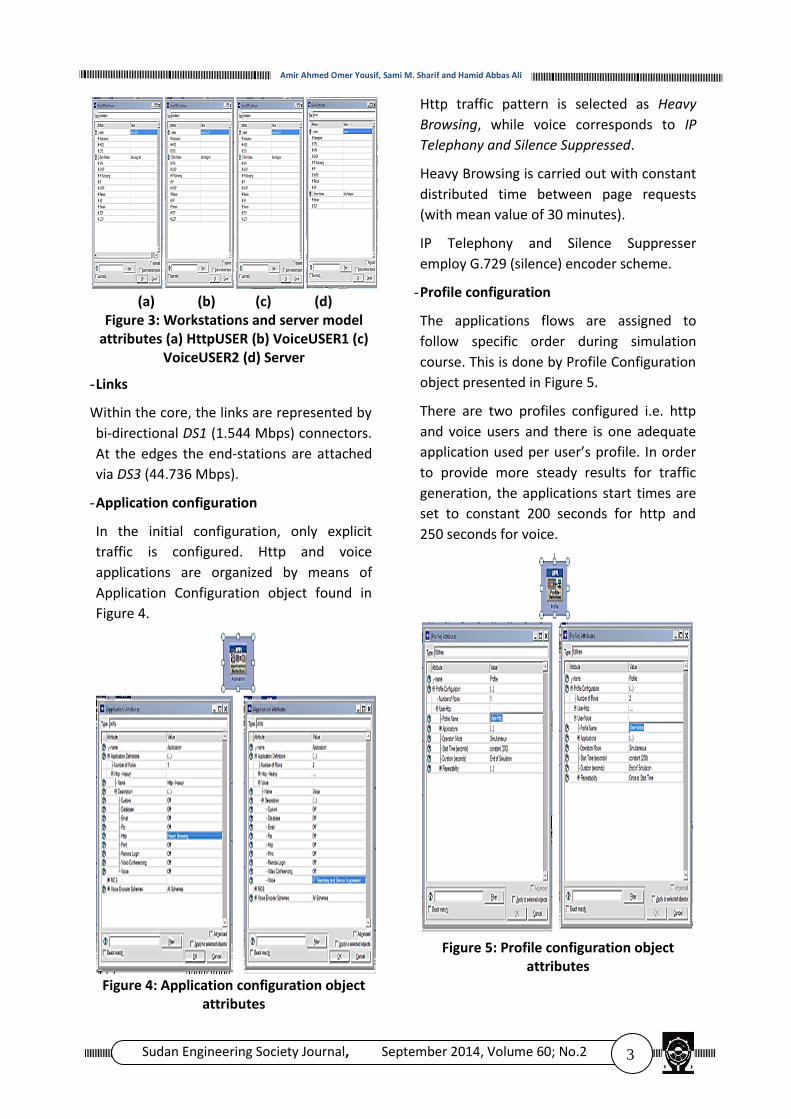
Figure 2: Network components and general
topology
The simulated network, as shown in Figure
2, consists of three areas namely Site1,
Internet Core, and Site2. There are four end
nodes out of which voiceUSER1 and
httpUSER are located at Site1 and SERVER
and voiceUSER2 are located at Site2. The
internet core consists of five routers:
LER_node_0, to LSR_node_4. These routers
are connected with point-to-point DS1
cables of data rate 1.54 Mbps. The end
nodes are connected to Internet Core with
point-to-point DS3 cables of data rate
44.736 Mbps. Simulation duration is set to
600 seconds. Figure 3 gives general
overview of the configurable parameters.
3 Sudan Engineering Society Journal, September 2014, Volume 60; No.2
Amir Ahmed Omer Yousif, Sami M. Sharif and Hamid Abbas Ali
(a) (b) (c) (d)
Figure 3: Workstations and server model attributes (a) HttpUSER (b) VoiceUSER1 (c)
VoiceUSER2 (d) Server
- Links
Within the core, the links are represented by
bi-directional DS1 (1.544 Mbps) connectors.
At the edges the end-stations are attached
via DS3 (44.736 Mbps).
- Application configuration
In the initial configuration, only explicit
traffic is configured. Http and voice
applications are organized by means of
Application Configuration object found in
Figure 4.
Figure 4: Application configuration object
attributes
Http traffic pattern is selected as Heavy
Browsing, while voice corresponds to IP
Telephony and Silence Suppressed.
Heavy Browsing is carried out with constant
distributed time between page requests
(with mean value of 30 minutes).
IP Telephony and Silence Suppresser
employ G.729 (silence) encoder scheme.
- Profile configuration
The applications flows are assigned to
follow specific order during simulation
course. This is done by Profile Configuration
object presented in Figure 5.
There are two profiles configured i.e. http
and voice users and there is one adequate
application used per user’s profile. In order
to provide more steady results for traffic
generation, the applications start times are
set to constant 200 seconds for http and
250 seconds for voice.
Figure 5: Profile configuration object
attributes

4 Sudan Engineering Society Journal, September 2014, Volume 60; No.2
COMPARISON BETWEEN NGN CORE NETWORKS PROTOCOL (MPLS) AND TRADITIONAL NETWORKS CORE PROTOCOLS (RIP & OSPF) USING OPNET
Traffic is mapped to specific workstations
with Application’s Supported Profiles. There
is one httpUSER that employs User-http
profiles. The other clients i.e. voiceUSER1
and voiceUSER2 have User-voice configured
as in Figure 6.
Figure 6: Application support profile for
workstation
2.2 Traffic Simulation
We have simulated web browsing and voice
application traffic using application and
profile configuration utilities provided by
OPNET IT Guru. To make simulated network
much more real we have added extra
background traffic with the help of a
demand model. The demand model is
connected between two tiers indicating the
traffic intensity in terms of Traffic (bits/sec)
and Traffic (packets/sec) and is set to
500,000 bits/sec and 500 packets/sec
respectively for each of the demand. In
Figures 7, 8, the demand models have been
set between all the end nodes shown using
purple colored links. For example line three
is a bidirectional traffic flow link between
httpUSER and SERVER.
Figure 7: Demand model for background
traffic
Traffic flow configuration attributes are
presented in Figure 8.
Figure 8: Traffic flow configuration
attributes
2.3 Simulation Scenarios
Three separate scenarios are created one
for each of the RIP, OSPF, and MPLS
protocol.
2.3.1 RIP Scenario
RIP is type of distance vector routing
algorithm. Hop count is used as routing
metric in RIP and a routing path from source
to destination can contain a maximum of 15
hops. The restriction on the number of hops
poses difficulty in building bigger networks
using RIP. RIP suffers from count to infinity
problem. RIP chooses only a single shortest

5 Sudan Engineering Society Journal, September 2014, Volume 60; No.2
Amir Ahmed Omer Yousif, Sami M. Sharif and Hamid Abbas Ali
path from source node to destination node
out of available shortest paths. This leads to
over utilization of chosen path and
underutilization of other paths. This is
illustrated by simulating the RIP network
using OPNET, as depicted in Figure 9.
Figure 9: RIP scenario
The RIP scenario involves the network
configured to work using RIP. Here all the
nodes and interfaces are configured to RIP.
RIP is configured with the default settings
that are not explained in details here. It
should be reminded that RIP uses hop-
count as the metric for destination
evaluation. RIP timers configuration can be
read from Figure 10.
It is obvious that RIP selection would not be
suitable for huge networks due to its 15-
hops count limit indicating infinity in routing
tables, which means no connectivity for
longer paths.
Figure 10: RIP configuration attributes (at
the router)
2.3.2 OSPF Scenario
OSPF is a type of interior gateway protocol.
OSPF creates network topology map using
link state information and it can detect link
failures and converge on an alternate
congestion free shortest path. OSPF on the
other hand, uses the available shortest
paths and distributes the load over two
chosen shortest paths, which leads to
efficient link utilization. This is illustrated by
simulating the OSPF network using OPNET
as shown in Figure 11.
Figure 11: OSPF scenario
This scenario is like RIP scenario (using the
same network), but here OSPF configured
on all interfaces and nodes. In the rest of
the simulation, <-> indicates a bidirectional
link between two nodes while -> and <-
represents unidirectional link.
OSPF has a hierarchical area structure and
does not have the hop limitation. There are
few key OSPF attributes explained below.
Other parameters description is skipped, as
they preserve their default configurations as
in Figure 12.
6 Sudan Engineering Society Journal, September 2014, Volume 60; No.2
COMPARISON BETWEEN NGN CORE NETWORKS PROTOCOL (MPLS) AND TRADITIONAL NETWORKS CORE PROTOCOLS (RIP & OSPF) USING OPNET
Figure 12: OSPF configuration attributes (at
the router)
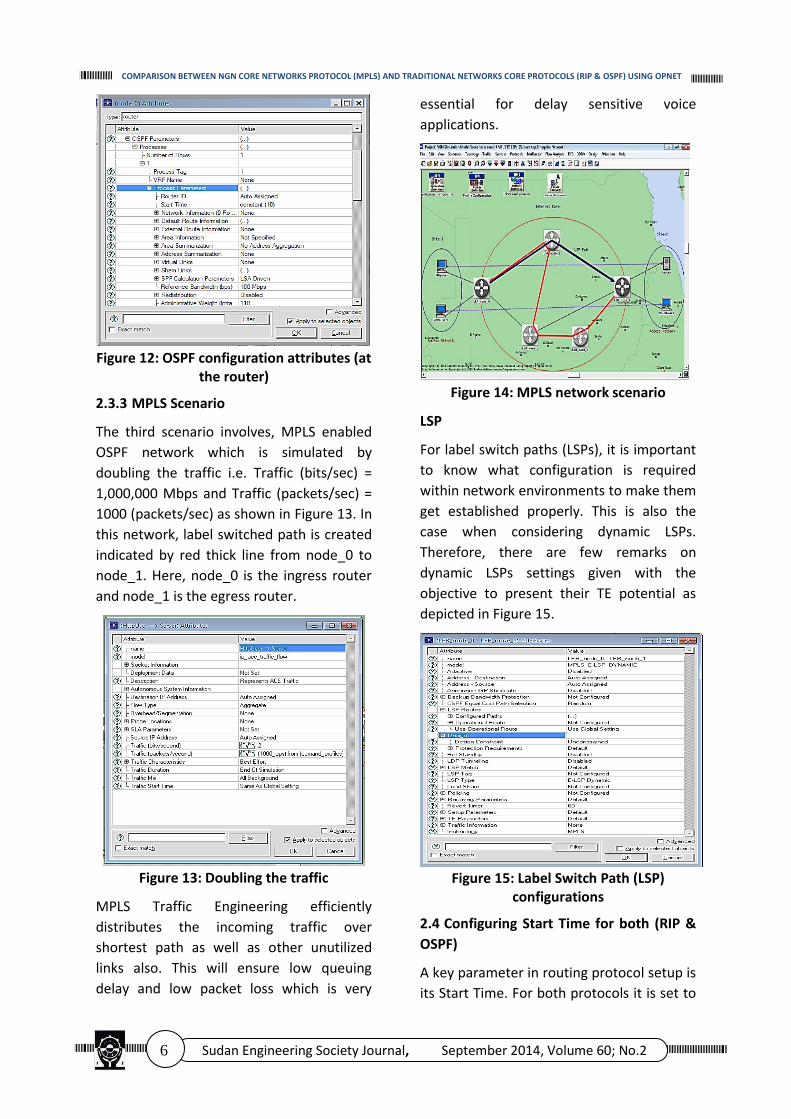
2.3.3 MPLS Scenario
The third scenario involves, MPLS enabled
OSPF network which is simulated by
doubling the traffic i.e. Traffic (bits/sec) =
1,000,000 Mbps and Traffic (packets/sec) =
1000 (packets/sec) as shown in Figure 13. In
this network, label switched path is created
indicated by red thick line from node_0 to
node_1. Here, node_0 is the ingress router
and node_1 is the egress router.
Figure 13: Doubling the traffic
MPLS Traffic Engineering efficiently
distributes the incoming traffic over
shortest path as well as other unutilized
links also. This will ensure low queuing
delay and low packet loss which is very
essential for delay sensitive voice
applications.
Figure 14: MPLS network scenario
LSP
For label switch paths (LSPs), it is important
to know what configuration is required
within network environments to make them
get established properly. This is also the
case when considering dynamic LSPs.
Therefore, there are few remarks on
dynamic LSPs settings given with the
objective to present their TE potential as
depicted in Figure 15.
Figure 15: Label Switch Path (LSP)
configurations
2.4 Configuring Start Time for both (RIP &
OSPF)
A key parameter in routing protocol setup is
its Start Time. For both protocols it is set to

7 Sudan Engineering Society Journal, September 2014, Volume 60; No.2
Amir Ahmed Omer Yousif, Sami M. Sharif and Hamid Abbas Ali
constant value of 10 seconds. Start Time
configuration remains important as RIP or
OSPF should begin its operation to build up
routing tables. The constant value is of
critical meaning for further network
configuration, as seen in Figure 16.
Figure 16: Configuring Start Time for both
(RIP & OSPF)
3 Simulation Results and Analysis
The simulation results are first obtained for
networks with RIP and OSPF routing
protocols. RIP, as mentioned earlier, is a
type of distance vector routing algorithm. A
routing path from source to destination can
contain a maximum of 15 hops. The
restriction on the number of hops posses a
difficulty in building bigger networks using
RIP. RIP suffers from count to infinity
problem. RIP chooses only a single shortest
path from source node to destination node
out of available shortest paths. This leads to
over utilization of a chosen path and
underutilization of other paths.
The result shows; network utilization which
is the ratio of current network traffic to the
maximum traffic that the port can handle,
network throughput which is the average
rate of successful message delivery over a
communication channel, and queuing
delay which is the time a job waits in a
queue until it can be executed.
3.1 Result of Scenario 1 (RIP)
The following figures show RIP scenario
result.
Figure 17: Link utilization in scenario1
Figure 18: Throughputs in scenario1
Figure 19: Queuing delays in scenario1
Figure 20: LER_node_0 <-> LSR_node_3
Utilization

8 Sudan Engineering Society Journal, September 2014, Volume 60; No.2
COMPARISON BETWEEN NGN CORE NETWORKS PROTOCOL (MPLS) AND TRADITIONAL NETWORKS CORE PROTOCOLS (RIP & OSPF) USING OPNET
Figure 21: LER_node_1 <-> LSR_node_3
utilization
Figure 22: LER_node_1 <-> LSR_node_3
queuing delay
3.2 Results of Scenario 2 (OSPF)
The following figures show RIP scenario results
Figure 23: Link utilization in scenario 2
Figure 24: Throughput in scenario2
Figure 25: Queuing delay in scenario2
Figure 26: LSR_node_2 <-> LER_node_0
utilization
Figure 27: LSR_node_2 <-> LER_node_1
utilization
Figure 28: LSR_node_2 <-> LER_node_1
queuing delay
9 Sudan Engineering Society Journal, September 2014, Volume 60; No.2
Amir Ahmed Omer Yousif, Sami M. Sharif and Hamid Abbas Ali
Figure 29: LSR_node_2 <-> LER_node_1
utilization in both RIP and OSPF
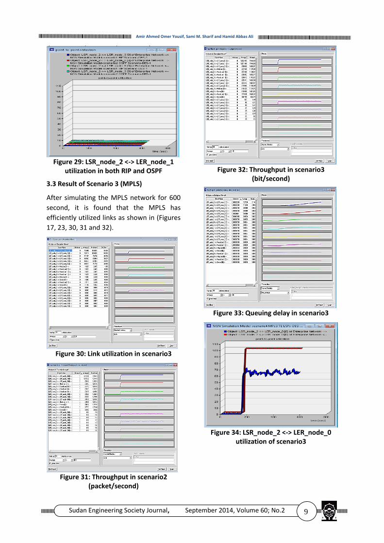
3.3 Result of Scenario 3 (MPLS)
After simulating the MPLS network for 600
second, it is found that the MPLS has
efficiently utilized links as shown in (Figures
17, 23, 30, 31 and 32).
Figure 30: Link utilization in scenario3
Figure 31: Throughput in scenario2
(packet/second)
Figure 32: Throughput in scenario3
(bit/second)
Figure 33: Queuing delay in scenario3
Figure 34: LSR_node_2 <-> LER_node_0
utilization of scenario3

10 Sudan Engineering Society Journal, September 2014, Volume 60; No.2
COMPARISON BETWEEN NGN CORE NETWORKS PROTOCOL (MPLS) AND TRADITIONAL NETWORKS CORE PROTOCOLS (RIP & OSPF) USING OPNET
Figure 35: LSR_node_2 <-> LER_node_1
utilization of scenario3
Figure 36: LSR_node_4 <-> LSR_node_3
queuing delay scenario3
3.4 Performance Comparison
Comparing results obtained from scenarios
for links utilization (Figures 17, 23, and 30),
throughput (Figures 18, 24, and 32) and
queuing delay (Figures 19, 25, and 33) the
following is concluded:
Utilization:
(a) (b) (c)
Figure 37: Link utilization comparison among (a) RIP (b) OSPF (c) MPLS
Figure 38: Link utilization comparison for
the scenarios
Throughput:
(a) (b) (c)
Figure 39: Throughput comparison among (a) RIP (b) OSPF (c) MPLS
Figure 40: Throughput performance
comparison for the scenarios
11 Sudan Engineering Society Journal, September 2014, Volume 60; No.2
Amir Ahmed Omer Yousif, Sami M. Sharif and Hamid Abbas Ali
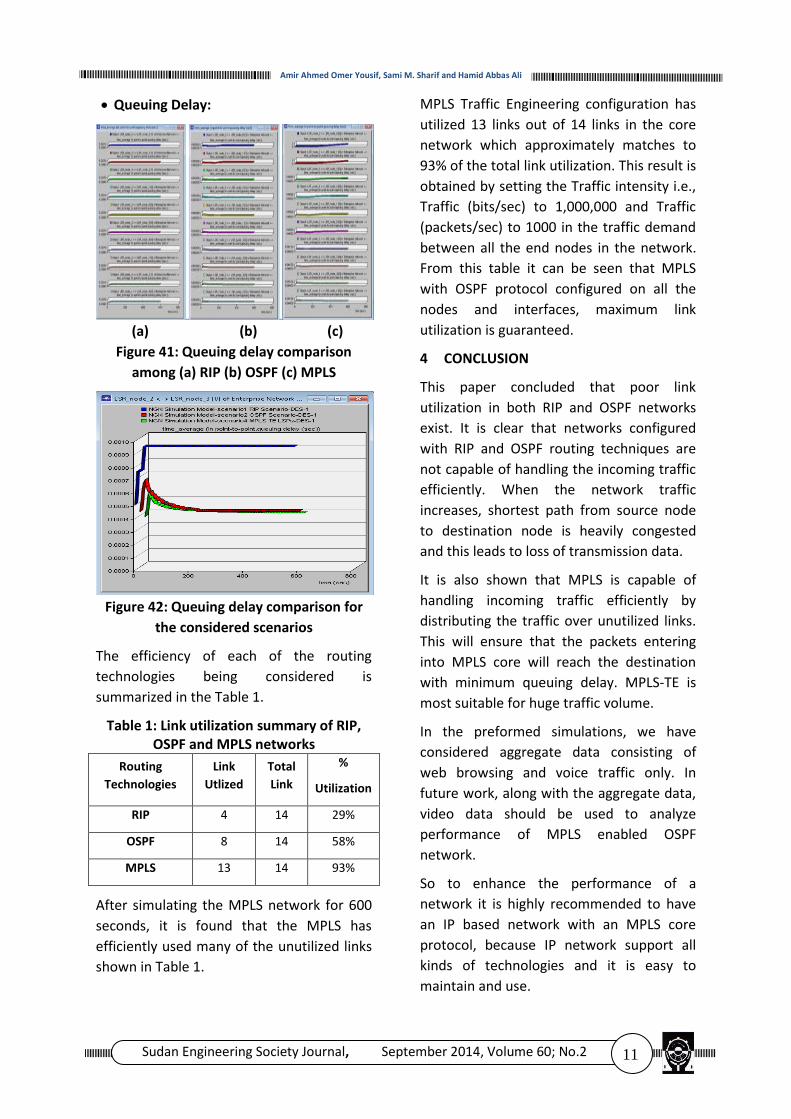
Queuing Delay:
(a) (b) (c)
Figure 41: Queuing delay comparison
among (a) RIP (b) OSPF (c) MPLS
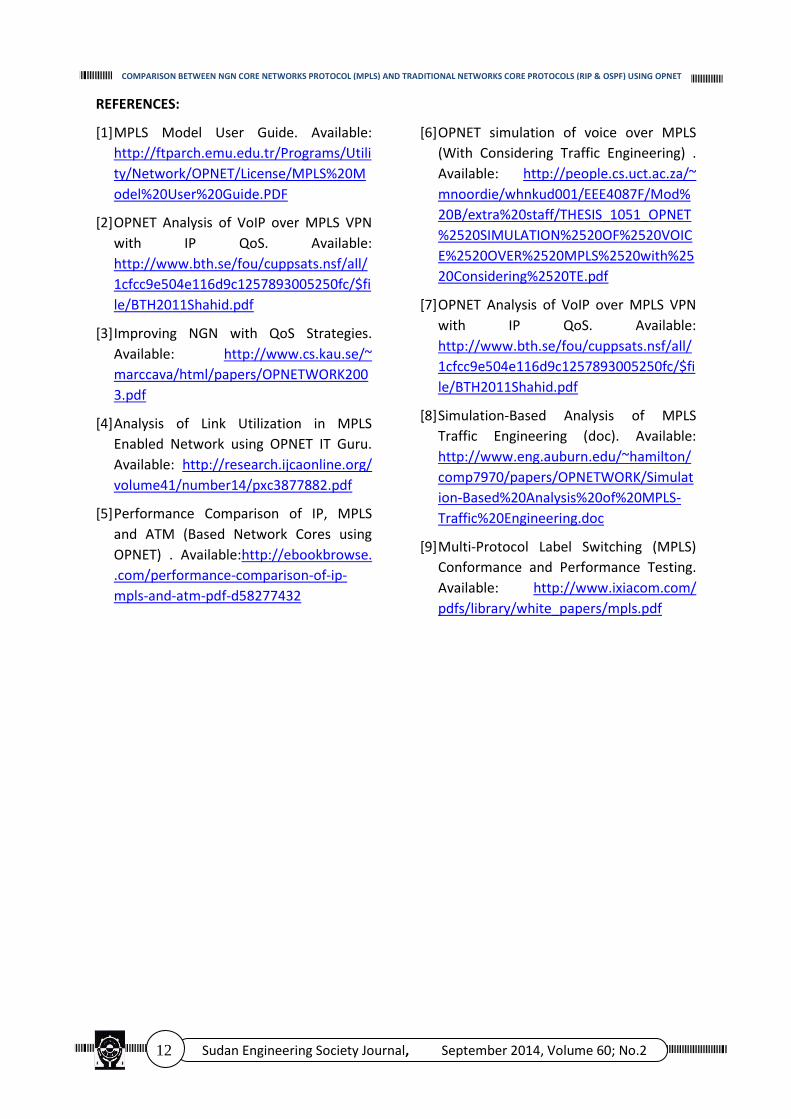
Figure 42: Queuing delay comparison for
the considered scenarios
The efficiency of each of the routing
technologies being considered is
summarized in the Table 1.
Table 1: Link utilization summary of RIP, OSPF and MPLS networks
Routing
Technologies
Link
Utlized
Total
Link
%
Utilization
RIP 4 14 29%
OSPF 8 14 58%
MPLS 13 14 93%
After simulating the MPLS network for 600
seconds, it is found that the MPLS has
efficiently used many of the unutilized links
shown in Table 1.
MPLS Traffic Engineering configuration has
utilized 13 links out of 14 links in the core
network which approximately matches to
93% of the total link utilization. This result is
obtained by setting the Traffic intensity i.e.,
Traffic (bits/sec) to 1,000,000 and Traffic
(packets/sec) to 1000 in the traffic demand
between all the end nodes in the network.
From this table it can be seen that MPLS
with OSPF protocol configured on all the
nodes and interfaces, maximum link
utilization is guaranteed.
4 CONCLUSION
This paper concluded that poor link
utilization in both RIP and OSPF networks
exist. It is clear that networks configured
with RIP and OSPF routing techniques are
not capable of handling the incoming traffic
efficiently. When the network traffic
increases, shortest path from source node
to destination node is heavily congested
and this leads to loss of transmission data.
It is also shown that MPLS is capable of
handling incoming traffic efficiently by
distributing the traffic over unutilized links.
This will ensure that the packets entering
into MPLS core will reach the destination
with minimum queuing delay. MPLS-TE is
most suitable for huge traffic volume.
In the preformed simulations, we have
considered aggregate data consisting of
web browsing and voice traffic only. In
future work, along with the aggregate data,
video data should be used to analyze
performance of MPLS enabled OSPF
network.
So to enhance the performance of a
network it is highly recommended to have
an IP based network with an MPLS core
protocol, because IP network support all
kinds of technologies and it is easy to
maintain and use.
12 Sudan Engineering Society Journal, September 2014, Volume 60; No.2
COMPARISON BETWEEN NGN CORE NETWORKS PROTOCOL (MPLS) AND TRADITIONAL NETWORKS CORE PROTOCOLS (RIP & OSPF) USING OPNET
REFERENCES:
[1] MPLS Model User Guide. Available:
http://ftparch.emu.edu.tr/Programs/Utili
ty/Network/OPNET/License/MPLS%20M
odel%20User%20Guide.PDF
[2] OPNET Analysis of VoIP over MPLS VPN
with IP QoS. Available:
http://www.bth.se/fou/cuppsats.nsf/all/
1cfcc9e504e116d9c1257893005250fc/$fi
le/BTH2011Shahid.pdf
[3] Improving NGN with QoS Strategies.
Available: http://www.cs.kau.se/~
marccava/html/papers/OPNETWORK200
3.pdf
[4] Analysis of Link Utilization in MPLS
Enabled Network using OPNET IT Guru.
Available: http://research.ijcaonline.org/
volume41/number14/pxc3877882.pdf
[5] Performance Comparison of IP, MPLS
and ATM (Based Network Cores using
OPNET) . Available:http://ebookbrowse.
.com/performance-comparison-of-ip-
mpls-and-atm-pdf-d58277432
[6] OPNET simulation of voice over MPLS
(With Considering Traffic Engineering) .
Available: http://people.cs.uct.ac.za/~
mnoordie/whnkud001/EEE4087F/Mod%
20B/extra%20staff/THESIS_1051_OPNET
%2520SIMULATION%2520OF%2520VOIC
E%2520OVER%2520MPLS%2520with%25
20Considering%2520TE.pdf
[7] OPNET Analysis of VoIP over MPLS VPN
with IP QoS. Available:
http://www.bth.se/fou/cuppsats.nsf/all/
1cfcc9e504e116d9c1257893005250fc/$fi
le/BTH2011Shahid.pdf
[8] Simulation-Based Analysis of MPLS
Traffic Engineering (doc). Available:
http://www.eng.auburn.edu/~hamilton/
comp7970/papers/OPNETWORK/Simulat
ion-Based%20Analysis%20of%20MPLS-
Traffic%20Engineering.doc
[9] Multi-Protocol Label Switching (MPLS)
Conformance and Performance Testing.
Available: http://www.ixiacom.com/
pdfs/library/white_papers/mpls.pdf