mp-series electric cylinders (series b and c)...
TRANSCRIPT

Installation Instructions
Original Instructions
MP-Series Electric Cylinders (Series B and C) Catalog Numbers MPAR-x1xxxB, MPAR-x1xxxE, MPAR-x2xxxC, MPAR-x2xxxF, MPAR-x3xxxE, MPAR-x3xxxH
Topic Page
Summary of Changes 2
About This Publication 2
Catalog Number Explanation 3
About the MP-Series Electric Cylinders 4
Before You Begin 5
Install the Electric Cylinder 8
Mount the Electric Cylinder 10
Change Connector Orientation 12
Dimensions 13
Connector Data 19
Commissioning 20
Maintenance 37
Troubleshooting 38
Accessories 40
Specifications 43
Additional Resources 45
MP-Series Electric Cylinders (Series B and C)
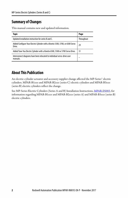
Summary of ChangesThis manual contains new and updated information.
About This PublicationAn electric-cylinder actuator and accessory supplier change affected the MP-Series™ electric cylinders. MPAR-B1xxx and MPAR-B2xxx (series C) electric cylinders and MPAR-B3xxx (series B) electric cylinders reflect the change.
See MP-Series Electric Cylinders (Series A and B) Installation Instructions, MPAR-IN003, for information regarding MPAR-B1xxx and MPAR-B2xxx (series A) and MPAR-B3xxx (series B) electric cylinders.
Topic Page
Updated installation instruction for series B and C. Throughout
Added Configure Your Electric Cylinder with a Kinetix 5500, 5700, or 6500 Servo Drive. 29
Added Tune You Electric Cylinder with a Kinetix 6500, 5500 or 5700 Servo Drive. 31
Interconnect diagrams have been relocated to individual servo-drive user manuals. –
2 Rockwell Automation Publication MPAR-IN001E-EN-P - November 2017

MP-Series Electric Cylinders (Series B and C)
Catalog Number Explanation Catalog numbers consist of various characters, each of which identifies a specific version or option for that component. Use this catalog explanation to understand the configuration of your actuator.
Motor Mounting (1)
A = Axial (in-line)B = Top (parallel)D = Left (parallel)E = Right (parallel) Holding Brake (1)
2 = No Brake4 = 24V DC BrakeFeedback (1)
M = Multi-turn, absolute high-resolution encoder, frame size 63 onlyV = Multi-turn, absolute high-resolution encoder, frame size 32 and 40 onlyMechanical Drive/Screw Lead, Motor Type B = 3.0 mm/rev (0.118 in./rev)C = 5.0 mm/rev (0.197 in./rev)E = 10.0 mm/rev (0.394 in./rev)F = 12.7 mm/rev (0.50 in./rev)H = 20.0 mm/rev (0.787 in./rev)Rod Stroke Length100 = 100 mm (3.94 in.)200 = 200 mm (7.87 in.)300 = 300 mm (11.81 in.)400 = 400 mm (15.75 in.)600 = 600 mm (23.62 in.)800 = 800 mm (27.56 in.)Actuator Frame Size1 = 322 = 403 = 63Voltage ClassA = 200VB = 400VX = Actuator cylinder replacement part (refer to Actuator Cylinders on page 43 for examples on how to order)Actuator TypeAR = Actuator RodBulletin NumberMP = MP-Series
(1) This field does not apply to actuator cylinder replacement parts.
MP AR - xx xxx x - x x x
MP AR - xx xxxxxx
Accessory Item NumberAccessory TypeNA = Axial (In-line) Mounting AccessoryNP = Parallel Mounting AccessoryNE = Rod-end AccessoryActuator TypeAR = Actuator RodBulletin NumberMP = MP-Series Actuator Accessory
Rockwell Automation Publication MPAR-IN001E-EN-P - November 2017 3

MP-Series Electric Cylinders (Series B and C)
About the MP-Series Electric CylindersMP-Series electric cylinders feature multi-turn high-resolution encoders and are available with 24V DC brakes. The MP-Series motor rotates a ballscrew drive that converts rotary motion into linear movement. This linear movement results in the extension and retraction of the piston rod from the electric cylinder housing
The MP-Series electric cylinders have been designed for exact positioning at high speeds.
IMPORTANT The MP-A/Bxxxxx-x2x electric cylinders are non-braking. When there is no input torque, the piston rod can be moved freely. You can achieve self-locking of your motion system by using motors with an integrated brake or with high self-braking torque.
Item Description
1 Power connector
2 Feedback connector
3 MP-Series motor
4 Motor mounting bolts
5 Actuator cylinder
6 Breather port
7 Hollow bolts with internal threads for fastening
8 Piston rod
9 Wrench flats to counteract torque on piston rod
10 Accessories mounting holes
8
7 (x4)
5
9
6
4 (x4)
1
3
MPAR-A1100E-V2A MP-Series Electric Cylinder
2
MPAR-A1100E-V2B MP-Series Electric Cylinder
10 (x4)
4 Rockwell Automation Publication MPAR-IN001E-EN-P - November 2017
MP-Series Electric Cylinders (Series B and C)
Before You Begin Remove all packing material, wedges, and braces from within and around the item. After unpacking, verify the nameplate catalog number against the purchase order.
1. Remove packaging polyethylene foil and cardboard.
The packing materials are recyclable, except for oiled paper, which is waste.
2. Remove the electric cylinder carefully from its shipping container.
Consider the weight of the electric cylinder. Depending on the design, the electric cylinder can weigh up to 20.6 kg (45.4 lb).
3. Visually inspect the electric cylinder for damage.
4. Examine the electric cylinder frame, piston shaft, and hollow bolts for defects.
5. Notify the carrier of shipping damage immediately
Planning Your InstallationSee the Kinetix® Motion Control Selection Guide, publication KNX-SG001, for the specifications and additional products referenced in this section:
• This product can be operated in compliance with the relevant safety regulations only if the maximum loading limits are observed.
• If you are mounting your electric cylinder in a vertical or sloping position, include safety measures that will control the workload if the spindle nut fails.
• Corrosive environments reduce the service life of electric cylinders.• Depending on the workload, the piston rod will bend. See the piston-rod deflection
specifications for limitations in Kinetix Linear Motion Specifications Technical Data, publication KNX-TD002.
ATTENTION: Do not attempt to open and modify the electric cylinder except to change the motor connector orientation as described on page 12. Only a qualified Allen-Bradley® employee can service the internal working of the electric cylinder or motor.Failure to observe these safety precautions could result in personal injury or damage to equipment.
ATTENTION: The electric-cylinder is not intended to be used in applications where side-loading occurs. Loads must be guided and supported. Aligned load with the line-of-motion of the piston rod. Side loading will reduce the lifetime of the electric-cylinder.
ATTENTION: Uncontrolled masses that are in motion can injure or damage property. If there is a spindle nut fracture inside the actuator cylinder due to wear, the working mass will drop down.Check whether additional external safety measures are required to prevent damage if the spindle nut fractures.
Rockwell Automation Publication MPAR-IN001E-EN-P - November 2017 5

MP-Series Electric Cylinders (Series B and C)
• Motor feedback, auxiliary feedback, and I/O connector kits are not included, but can be purchased separately.
• Factory manufactured feedback and power cables are available in standard cable lengths. They provide environmental sealing and shield termination. Contact your Allen-Bradley sales office or refer to the selection guide for cables.
Electric Cylinders with Brake OptionThe brake option on this servo motor is a spring-set holding brake that releases when voltage is applied to the brake coil. A separate power source is required to disengage the brake. A servo motor controller or manual operator control can apply the power source.
If system main power fails, holding brakes can withstand occasional use as stopping brakes. However, the rotational mechanical backlash that is created can potentially damage to the system, increases brake wear, and reduces brake life.
An unpowered electric cylinder will require a brake to maintain its position if the force on the actuator exceeds the Back Drive Force that is listed in Kinetix Linear Motion Specifications Technical Data, publication KNX-TD002.
A brake can be used to prevent the actuator from backdriving, typically in vertical applications. A brake can be used for safety reasons or to hold the position of the actuator when unpowered for energy savings
IMPORTANT Holding brakes are not designed to stop rotation of the motor shaft, nor are they intended to be used as a safety device. They are designed to hold a motor shaft at 0 rpm for up to the rated brake holding torque.
The recommended method to prevent the motor shaft from rotation is a four-step process: 1. Command the servo drive to 0 rpm.2. Verify that the motor is at 0 rpm.3. Engage the brake.4. Disable the drive.A disable drive removes the potential for brake wear that shaft oscillations cause when you
have a poorly tuned servo system.
6 Rockwell Automation Publication MPAR-IN001E-EN-P - November 2017
MP-Series Electric Cylinders (Series B and C)
Preventing Electrical NoiseElectromagnetic interference (EMI), commonly called electrical noise, can reduce motor performance. Effective techniques to counter EMI include filtering the AC power, by using shielded cables, signal cables separation from power wiring, and the practice of good grounding techniques.
Follow these guidelines to avoid the effects of EMI:
• Isolate the power transformers or install line filters on all AC input power lines.• Physically separate signal cables from motor cabling and power wiring. Do not route
signal cables with motor and power wires, or over the vent openings of servo drives.• Ground all equipment by using a single-point parallel ground system that employs
ground bus bars or large straps. If necessary, use additional electrical-noise reduction techniques to reduce EMI in noisy environments.
See System Design for Control of Electrical Noise Reference Manual, publication GMC-RM001, for additional information on reducing the effects of EMI.
Build and Route CablesKnowledgeable cable routing and careful cable construction improve system electromagnetic compatibility (EMC).
Follow these steps to build and install cables.
1. Keep wire lengths as short as physically possible.
2. Route signal cables (encoder, serial, analog) away from motor and power wiring.
3. Separate cables by 0.3 m (1 ft) minimum for every 9 m (30 ft) of parallel run.
4. Ground both ends of the encoder cable shield and twist the signal wire pairs to prevent electromagnetic interference (EMI) from other equipment.
ATTENTION: If the shield is not grounded, high voltage can be present on the power cable shield.Make sure that there is a connection to ground for any power cable shield.Failure to observe these safety precautions could result in personal injury or damage to equipment.
Rockwell Automation Publication MPAR-IN001E-EN-P - November 2017 7

MP-Series Electric Cylinders (Series B and C)
Install the Electric CylinderThe installation must comply with all local regulations and use of equipment and installation practices that promote electromagnetic compatibility and safety
Follow these steps to install the electric cylinder.
1. Provide sufficient clearances in the area of the electric cylinder for it to stay within its specified operating temperature range.
See Specifications on page 43 for the operating temperature range. Do not enclose the electric cylinder unless forced air is blown across the electric cylinder for cooling. Keep devices that produce heat away from the electric cylinder.
2. Make sure that the mounting surface supports the electric cylinder evenly so that it is free of mechanical stress and distortion.
ATTENTION: Unmounted electric cylinders, disconnected mechanical couplings, and disconnected cables are dangerous if power is applied.Appropriately identify disassembled equipment (tagged-out) and access to electrical power restricted (locked-out). Failure to observe these safety precautions could result in personal injury.
ATTENTION: Make sure that cables are installed and restrained to prevent uneven tension or flexion at the cable connectors.Excessive and uneven lateral force at the cable connectors can cause the environmental seal of the connector to open and close as the cable flexes.Failure to observe these safety precautions could result in damage to the electric cylinder motor and its components.
ATTENTION: Damage can occur to the electric cylinder bearings and the feedback device if a sharp impact to the piston rod is applied during installation. Do not strike the piston rod with tools during installation or removal.Do not attempt to rotate the piston rod during installation. If the piston rod rotates, the mechanism that allows the electric cylinder to extend and retract will break.Failure to observe these safety precautions could result in damage to the electric cylinder and its components.
IMPORTANT Position the electric cylinder so that all operating parts are accessible and the breather port is not covered.
8 Rockwell Automation Publication MPAR-IN001E-EN-P - November 2017

MP-Series Electric Cylinders (Series B and C)
The evenness of support surface must be ≤ 0.2 mm (0.008 in.).
3. Attach mounting accessories to the electric cylinder; see Accessories on page 40.
Tighten the fastening screws evenly.
4. Attach rod-end accessories and the workload.
Be sure that the workload center of gravity is centric to the piston rod.
When fastening a rod-end accessory or workload to the piston rod, use two wrenches. Use one wrench to tighten the mounting nut or rod-end accessory and the other, on the piston-rod wrench flats, to counteract the applied torque. Be sure that the torque is not applied to the piston rod and that the piston rod does not rotate.
ATTENTION: Do not modify the settings of the screws and the threaded pins.Do not fasten the electric cylinder by the front cover alone when used with high loads.Heavy tensile strain can cause the screws in the cover to pull out.
Attribute Frame 32 Frame 40 Frame 63
Internal thread of cover screws M6 M6 M8
Torque, max (1)
(1) Unless otherwise noted, the torque value has a ±20% tolerance.
5 N•m(3.69 lb•ft)
5 N•m(3.69 lb•ft)
9 N•m(5.90 lb•ft)
ATTENTION: Damage can occur to the electric cylinder bearings and the feedback device if sharp impact to the piston rod is applied during installation. Do not strike the piston rod with tools during installation or removal.
Failure to observe these safety precautions could result in damage to the electric cylinder and its components.
IMPORTANT Do not twist or rotate the piston rod. If the piston rod is rotated, the absolute position of the electric cylinder will be lost and the absolute home position must be re-established.
Rockwell Automation Publication MPAR-IN001E-EN-P - November 2017 9

MP-Series Electric Cylinders (Series B and C)
If you are using a trunnion mounting kit, catalog number MPAR-NA1635xx, see page 42 for torque values.
If you are using a rod guide accessory, catalog number MPAR-NE34xxx or MPAR-NE150xxx, adjust the guides of the workload and the electric cylinder so that they are exactly parallel. This alignment avoids excessive wear on the guide.
Mount the Electric Cylinder
1. Use stainless steel fasteners to mount your electric cylinder to your application.
2. Attach power and feedback cables after the electric cylinder is mounted, and use a drip loop in the cable to keep liquids away from the connectors.
Frame Size Piston Rod Thread Wrench Flats Width
32 M10 x 1.25 10 mm 40 M12 x 1.25 13 mm
63 M16 x 1.5 17 mm
ATTENTION: Do not rotate the piston rod during installation. If the piston rod rotates, the mechanism that allows the electric cylinder to extend and retract will break. Use two wrenches to install the workload.Failure to observe these safety precautions could result in damage to the electric cylinder and its components
BURN HAZARD: Outer surfaces of the motor can reach high temperatures, 65 °C (149 °F), during electric cylinder operation. To prevent accidental contact with hot surfaces, take precautions. Failure to observe these safety precautions can result in personal injury.
ATTENTION: Consider electric-cylinder surface temperature when selecting motor-mating connections and cables. Failure to observe these safety precautions can result in personal injury or damage to equipment.
ATTENTION: Keyed connectors must be properly aligned and hand-tightened the recommended number of turns. The need for excessive force such as the need for the use of tools to fully seat connectors indicates improper connector alignment.Failure to observe these safety precautions could result in damage to the motor and cable, and their components.
Wrench Flat
10 Rockwell Automation Publication MPAR-IN001E-EN-P - November 2017
MP-Series Electric Cylinders (Series B and C)
Attach Motor CablesFollow these steps to attach the power and feedback cables after the electric-cylinder is mounted.
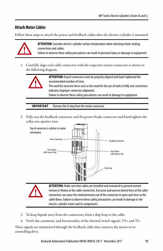
1. Carefully align each cable connector with the respective motor connector as shown in the following diagram.
2. Fully seat the feedback connector and the power/brake connector and hand tighten the collar one-quarter turn.
3. To keep liquids away from the connectors, form a drip loop in the cable.
4. Verify the continuity and functionality of the thermal switch signals, TS+ and TS-.
These signals are transmitted through the feedback cable that connects the motor to its controlling drive.
ATTENTION: Consider electric-cylinder surface temperature when selecting motor-mating connections and cables.Failure to observe these safety precautions can result in personal injury or damage to equipment.
ATTENTION: Keyed connectors must be properly aligned and hand-tightened the recommended number of turns.The need for excessive force such as the need for the use of tools to fully seat connectors indicates improper connector alignment.Failure to observe these safety precautions can result in damage to equipment.
IMPORTANT Remove the O-ring from the motor connector.
ATTENTION: Make sure that cables are installed and restrained to prevent uneven tension or flexion at the cable connectors. Excessive and uneven lateral force at the cable connectors can cause the environmental seal of the connector to open and close as the cable flexes. Failure to observe these safety precautions can result in damage to the electric-cylinder motor and its components.
Flat Surfacewith Logo on Top
Top of connector is relative to motor orientation.
Feedback Connector
Drip Loop
Power Connector
Flat Surface with Logo on Top
Rockwell Automation Publication MPAR-IN001E-EN-P - November 2017 11
MP-Series Electric Cylinders (Series B and C)
Change Connector OrientationYou can rotate the circular DIN-connector housings up to 180° in either direction.
Follow these steps to rotate the DIN connectors.
1. Mount and fully seat a mating cable on the connector.
2. Grasp the connector and cable plug by their housings and slowly rotate them to the outside of the motor.
If necessary, repeat this step for each connector (feedback or power/brake).
ATTENTION: You can rotate the connectors into a fixed position during installation of the electric cylinder and keep them in that position without further adjustment. Strictly limit the applied forces and the number of times the connector is rotated to be sure that connectors meet the requirements of IP66 for the motor portion of the electric cylinder. Failure to observe these safety precautions can result in damage to the motor and its components
ATTENTION: Apply force only to the connectors; do not apply force to the cable. Do not use tools, for example, pliers and vise-grips, to assist with the rotation of the connector. Failure to observe these safety precautions can result in personal injury or damage to equipment.
12 Rockwell Automation Publication MPAR-IN001E-EN-P - November 2017

MP-Series Electric Cylinders (Series B and C)
Dimen
sions
22.0
(0.87
)12
2 +(4
.80) +
L7
148 ±
1 +
(5.83
± 0.
04))
+
LE
LB
90.0
±1.0
(3.54
± 0.
04)
27.5
(1.10
)
66.5
(2.62
)
LB56
.3(2
.22)
32.5
(1.28
)32
.5(1
.28)
60.0
(2.36
)
157.0
(6.18
)
L71
Ø30.0
(1.18
) d11Ø1
6.0(0
.63) h
9
12.0
(0.47
)M10
x 1.2
5
10
16.0
(0.63
)
26.0
(1.02
)
10.0
(0.39
)
18.0
(0.71
)
45.5
(1.79
)
45.5
(1.79
)
6.0 (0
.24)
(x4)
M6 (
x4)
32.5
(1.28
)32
.5(1
.28)
55.0
(2.16
)
66.5
(2.62
)94 (3.70
)
24.0
(0.94
)26
.0(1
.02)
Deta
il A
+ =
Plus
Stro
ke Le
ngth
See D
etail
A
MP-
Serie
s Ele
ctric
Cylin
ders
(Fra
me 3
2)
Dim
ensio
ns ar
e with
pisto
n ro
d full
y ret
racte
d.
Dim
ensio
ns ar
e in m
m (in
.).
Flat f
or w
rench
.
Bulle
tin M
PAR-x1xxxx-xxA
(in-
line c
onfig
urat
ion)
Powe
r/Bra
keCo
nnec
tor
Feed
back
Conn
ecto
r
MPA
R-x1xxxx-xxB
MPA
R-x1xxxx-xxD
MPA
R-x1xxxx-xxE
Bulle
tin M
PAR-x1xxxx-xxB
/D/E
(par
allel
conf
igurat
ion)
Rockwell Automation Publication MPAR-IN001E-EN-P - November 2017 13

MP-Series Electric Cylinders (Series B and C)
MP-Series Electric Cylinder Dimensions (In-line Configuration, Frame 32)
Electric Cylinder Cat. No. L7(1)
mm (in.)
(1) If you are ordering an MPAR-x1xxxx-V4x actuator with brake, add 36.1 mm (1.42 in.) to dimensions L7 and LB.
LB (1)
mm (in.)LE (2)
mm (in.)
(2) If you are ordering an MPAR-x1xxxx-V4x actuator with brake, add 33.4 mm (1.31 in.) to dimension LE.
MPAR-x1100B-V2A 445.7 (17.55)
126.5 (4.98) 52.4 (2.06)MPAR-x1200B-V2A 545.7 (21.48)
MPAR-x1300B-V2A 645.7 (25.42)
MPAR-x1400B-V2A 745.7 (29.36)
MPAR-x1100E-V2A 470.7 (18.53)
151.5 (5.96) 77.2 (3.04)MPAR-x1200E-V2A 570.7 (22.47)
MPAR-x1300E-V2A 670.7 (26.41)
MPAR-x1400E-V2A 770.7 (30.34)
MP-Series Electric Cylinder Dimensions (Parallel Configuration, Frame 32) (1)
(1) For the complete dimension of the parallel configuration electric cylinders, use the in-line dimensions for an electric cylinder with the same rod-stroke length and the dimensions from this table.
Electric Cylinder Cat. No. L71 mm (in.)
MPAR-x1100B-V2B/D/E 326.3 (12.8)
MPAR-x1200B-V2B/D/E 426.3 (16.8)
MPAR-x1300B-V2B/D/E 526.3 (20.7)
MPAR-x1400B-V2B/D/E 626.3 (24.6)
14 Rockwell Automation Publication MPAR-IN001E-EN-P - November 2017

MP-Series Electric Cylinders (Series B and C)
24.0
(0.94
)14
6.5 +
(5.77
+)
L7
176.5
± 1
+(6
.95 ±
.04 +
)
LE
LB
C
CG
AD
LBLC
38.0
(1.50
)38
.0(1
.50)
PW
HC
L71
Ø 35
.0(1
.38) d
11Ø 20
.0(0
.79) h
9
16.0
(0.63
)M12
x 1.2
5
13
16.0
(0.63
)
30.0
(1.18
)
10.5
(0.41
)
21.5
(0.85
)
54.0
(2.13
)
54.0
(2.13
)
6.0 (0
.24)
(x4)
M6 (
x4)
38.0
(1.50
)38
.0(1
.50)
P
AD
HD
28.5
(1.12
)30
.0(1
.18)
+ =
Plus
Stro
ke Le
ngth
Powe
r/Bra
keCo
nnec
tor
Feed
back
Conn
ecto
r
See D
etail
A
MP-
Serie
s Ele
ctric
Cylin
ders
(Fra
me 4
0)
Dim
ensio
ns ar
e with
pisto
n ro
d ful
ly re
tracte
d.
Dim
ensio
ns ar
e in m
m (i
n.).
Flat f
or w
rench
.
Bulle
tin M
PAR-x2xxxx-xxA
(in-
line c
onfig
urat
ion)
MPA
R-x2xxxx-xxB
Det
ail A
MPA
R-x2xxxx-xxD
MPA
R-x2xxxx-xxE
Bulle
tin M
PAR-x2xxxx-xxB
/D/E
(par
allel
conf
igura
tion)
15 Rockwell Automation Publication MPAR-IN001E-EN-P - November 2017
MP-Series Electric Cylinders (Series B and C)
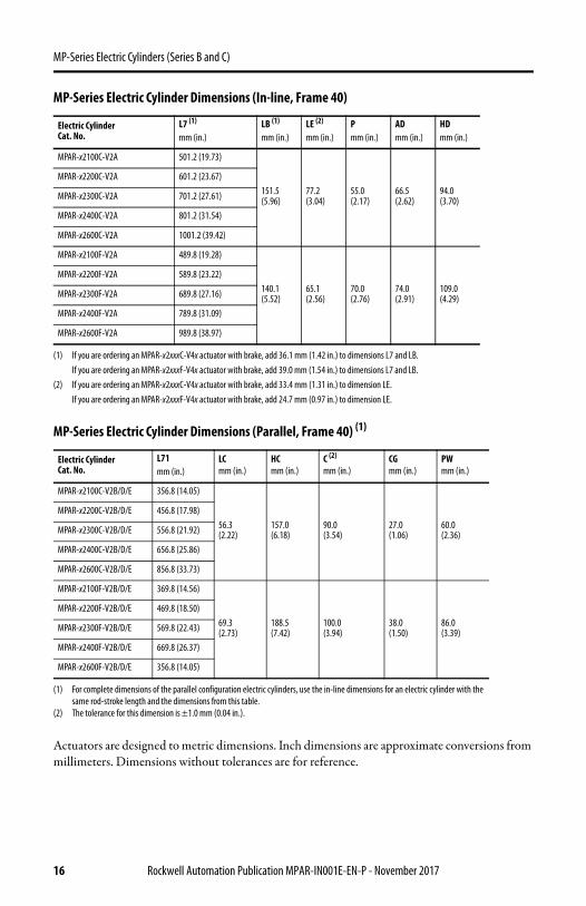
Actuators are designed to metric dimensions. Inch dimensions are approximate conversions from millimeters. Dimensions without tolerances are for reference.
MP-Series Electric Cylinder Dimensions (In-line, Frame 40)
Electric Cylinder Cat. No.
L7 (1)
mm (in.)LB (1)
mm (in.)LE (2)
mm (in.)Pmm (in.)
ADmm (in.)
HDmm (in.)
MPAR-x2100C-V2A 501.2 (19.73)
151.5(5.96)
77.2(3.04)
55.0(2.17)
66.5(2.62)
94.0(3.70)
MPAR-x2200C-V2A 601.2 (23.67)
MPAR-x2300C-V2A 701.2 (27.61)
MPAR-x2400C-V2A 801.2 (31.54)
MPAR-x2600C-V2A 1001.2 (39.42)
MPAR-x2100F-V2A 489.8 (19.28)
140.1(5.52)
65.1(2.56)
70.0(2.76)
74.0(2.91)
109.0(4.29)
MPAR-x2200F-V2A 589.8 (23.22)
MPAR-x2300F-V2A 689.8 (27.16)
MPAR-x2400F-V2A 789.8 (31.09)
MPAR-x2600F-V2A 989.8 (38.97)
(1) If you are ordering an MPAR-x2xxxC-V4x actuator with brake, add 36.1 mm (1.42 in.) to dimensions L7 and LB.If you are ordering an MPAR-x2xxxF-V4x actuator with brake, add 39.0 mm (1.54 in.) to dimensions L7 and LB.
(2) If you are ordering an MPAR-x2xxxC-V4x actuator with brake, add 33.4 mm (1.31 in.) to dimension LE.If you are ordering an MPAR-x2xxxF-V4x actuator with brake, add 24.7 mm (0.97 in.) to dimension LE.
MP-Series Electric Cylinder Dimensions (Parallel, Frame 40) (1)
Electric Cylinder Cat. No.
L71mm (in.)
LCmm (in.)
HCmm (in.)
C (2) mm (in.)
CG mm (in.)
PWmm (in.)
MPAR-x2100C-V2B/D/E 356.8 (14.05)
56.3(2.22)
157.0(6.18)
90.0(3.54)
27.0(1.06)
60.0(2.36)
MPAR-x2200C-V2B/D/E 456.8 (17.98)
MPAR-x2300C-V2B/D/E 556.8 (21.92)
MPAR-x2400C-V2B/D/E 656.8 (25.86)
MPAR-x2600C-V2B/D/E 856.8 (33.73)
MPAR-x2100F-V2B/D/E 369.8 (14.56)
69.3(2.73)
188.5(7.42)
100.0(3.94)
38.0(1.50)
86.0(3.39)
MPAR-x2200F-V2B/D/E 469.8 (18.50)
MPAR-x2300F-V2B/D/E 569.8 (22.43)
MPAR-x2400F-V2B/D/E 669.8 (26.37)
MPAR-x2600F-V2B/D/E 356.8 (14.05)
(1) For complete dimensions of the parallel configuration electric cylinders, use the in-line dimensions for an electric cylinder with the same rod-stroke length and the dimensions from this table.
(2) The tolerance for this dimension is ±1.0 mm (0.04 in.).
16 Rockwell Automation Publication MPAR-IN001E-EN-P - November 2017

MP-Series Electric Cylinders (Series B and C)
32.0
(1.26
)17
7.0 +
(6.97
+)
L7
214.0
± 1
+(8
.43 ±
0.04
+)
LE
LB
120 ±
1.0
(4.72
± 0.
04)
45.0
(1.77
)
AD
LB82
.3(3
.24)
56.5
(2.22
)56
.5(2
.22)
110.0
(4.33
)
225.0
(8.86
)
L71
Ø 45
.0(1
.77) d
11Ø 28
.0(1
.10) h
9
20.0
(0.79
)M16
X 1.5
17
17.0
(0.67
)
37.0
(1.46
)
15.0
(0.59
)
28.5
(1.12
)
75.5
(2.97
)
8.0 (0
.31)
(x4)
M8 (
x4)
56.5
(2.22
)
75.5
(2.97
)56
.5(2
.22)
P
AD
HD
34.0
(1.34
)36
.0(1
.42)
+ =
Plus
Stro
ke Le
ngth
Powe
r/Bra
keCo
nnec
tor
See D
etail
A
MP-
Serie
s Ele
ctric
Cylin
ders
(Fra
me 6
3)Di
men
sions
are i
n mm
(in.).
Dim
ensio
ns ar
e with
pis
ton r
od fu
lly re
tracte
d.
Feed
back
Conn
ecto
r
Flat f
or w
renc
h.
Deta
il A
Bulle
tin M
PAR-x3xxxx-xxA
(in-li
ne co
nfigu
ratio
n)
Bulle
tinM
PAR-x3xxxx-xxB
/D/E
(par
allel
conf
igura
tion)
MPA
R-x3xxxx-x
xB MPA
R-x3xxxx-xxD
MPA
R-x3xxxx-xxE
Rockwell Automation Publication MPAR-IN001E-EN-P - November 2017 17

MP-Series Electric Cylinders (Series B and C)
MP-Series Electric Cylinder Dimensions (In-line, Frame 63)
Electric Cylinder Cat. No.
L7 (1)
mm (in.)
(1) If you are ordering an MPAR-x3xxxE-M4x actuator with brake, add 34.5 mm (1.36 in.) to dimensions L7 and LB.If you are ordering an MPAR-x3xxxH-M4x actuator with brake, add 48.5 mm (1.91 in.) to dimensions L7 and LB.
LB (1)
mm (in.)LE (2)
mm (in.)
(2) If you are ordering an MPAR-x3xxxE-M4x actuator with brake, add 34.5 mm (1.36 in.) to dimension LE.If you are ordering an MPAR-x3xxxH-M4x actuator with brake, add 48.5 mm (1.91 in.) to dimension LE.
Pmm (in.)
ADmm (in.)
HDmm (in.)
MPAR-x3100E-M2A 595.9 (23.46)
178.8(7.04)
121.5(4.78)
89.4(3.52)
80.9(3.19)
125.7(4.95)
MPAR-x3200E-M2A 695.9 (27.40)
MPAR-x3300E-M2A 795.9 (31.33)
MPAR-x3400E-M2A 895.9 (35.27)
MPAR-x3600E-M2A 1095.9 (43.15)
MPAR-x3800E-M2A 1295.9 (51.02)
MPAR-x3100H-M2A 574.8 (22.63)
149.8(5.90)
92.5(3.64)
98.3(3.87)
83.9(3.30)
132.8(5.23)
MPAR-x3200H-M2A 674.8 (26.57)
MPAR-x3300H-M2A 774.8 (30.50)
MPAR-x3400H-M2A 874.8 (34.44)
MPAR-x3600H-M2A 1074.8 (42.31)
MPAR-x3800H-M2A 1274.8 (50.19)
MP-Series Electric Cylinder Dimensions (Parallel, Frame 63)
Electric Cylinder Cat. No.
L71mm (in.)
MPAR-x3100x-M2B/D/E 428.3 (16.86)
MPAR-x3200x-M2B/D/E 528.3 (20.80)
MPAR-x3300x-M2B/D/E 628.3 (24.74)
MPAR-x3400x-M2B/D/E 728.3 (28.67)
MPAR-x3600x-M2B/D/E 928.3 (36.55)
MPAR-x3800x-M2B/D/E 1128.3 (44.42)
18 Rockwell Automation Publication MPAR-IN001E-EN-P - November 2017

MP-Series Electric Cylinders (Series B and C)
Connector DataThis table lists the signal descriptions for feedback, power, and brake connector pins on the electric cylinder.
Feedback Power and Brake
PinSignal Name MPAR-Axxxxx (200V Class)
Signal Name MPAR-Bxxxxx (400V Class)
Pin Signal Name
1 Sin+ Sin+ A Phase U (1)
(1) Power pins A, B, C, and D can be labeled as U, V, W, and GND respectively. Brake pins F and G can be labeled as + and - respectively. Reserved pins E and H can be numbered 1 or 2.
2 Sin- Sin- B Phase V (1)
3 Cos+ Cos+ C Phase W (1)
4 Cos- Cos- D Ground (1)
5 Data+ Data+ E Reserved (1)
6 Data- Data- F MBRK+ (1) (2)
(2) Brake+ and Brake- are available only on electric cylinders with a brake.
7Reserved
Reserved
G MBRK- (1) (2)
8 HReserved
9 +5V DC L
10 CommonCase Cable shield and
GND11Reserved
+9V DC
12 Common
13 TS+ TS+
14 TS- TS-
15
Reserved Reserved16
17
Case Shield Shield
ATTENTION: Be sure that cables are installed and restrained to prevent uneven tension or flexion at the cable connectors. Excessive and uneven force at the cable connector can result in damage to the housing and contacts as the cable flexes. Failure to observe these safety precautions can result in damage to the motor and its components.
A
CB
D
EHLFG
Intercontec P/N BEDC0091NN00000217000
12
34
56
78
9
1011 12
13
1415
16
17
Intercontec P/NAEDC113NN00000222000
Rockwell Automation Publication MPAR-IN001E-EN-P - November 2017 19

MP-Series Electric Cylinders (Series B and C)
Mating Cables
CommissioningThis section provides guidelines for using Studio 5000 Logix Designer® application to configure your electric-cylinder servo drive system.
Configure Your Electric CylinderConfigure the electric-cylinder by using the basic parameter settings that are described in this section. Use the procedure appropriate for your motion axis
Connector Cable Type Cable Cat. No.
Feedback
Premolded2090-CFBM7DD-CEAAxx (standard) or2090-CFBM7DD-CEAFxx (continuous-flex)
Flying lead2090-CFBM7DF-CEAAxx (standard) or2090-CFBM7DF-CEAFxx (continuous-flex)
Power
With brake wires2090-CPBM7DF-xxAAxx (standard) or2090-CPBM7DF-xxAFxx (continuous-flex)
Without brake wires2090-CPWM7DF-xxAAxx (standard) or2090-CPWM7DF-xxAFxx (continuous-flex)
Drive See:
Kinetix 350Kinetix 2000Kinetix 6000Kinetix 6200
Configure Your Electric Cylinder and Kinetix 350, 2000, 6000, or 6200 Servo Drive on page 21, and Tune Your Electric Cylinder and Kinetix 350, 2000, 6000, or 6200 Servo Drive on page 26.
Kinetix 5500Kinetix 5700Kinetix 6500
Configure Your Electric Cylinder with a Kinetix 5500, 5700, or 6500 Servo Drive on page 29, and Tune You Electric Cylinder with a Kinetix 6500, 5500 or 5700 Servo Drive on page 31
Ultra™ 3000 Configure Your Electric Cylinders with Ultraware Software on page 32.
Kinetix 300 Configure the Kinetix 300 Drive for Electric Cylinders on page 34
ATTENTION: Parts that move can cause injuries. Before running the electric cylinder, make sure that all components are secure and safeguards are in place to prevent access to the path of machinery in motion.Safeguards must prevent access to the electric cylinder until all motion has stopped.Check that the electric cylinder is clear of foreign matter and tools. Objects hit by the moving piston rod can become projectiles that can cause personal injury or damage equipment.
IMPORTANT It is your responsibility to verify that the servo control system safely controls the electric cylinder regarding maximum force, acceleration, and speed.
20 Rockwell Automation Publication MPAR-IN001E-EN-P - November 2017

MP-Series Electric Cylinders (Series B and C)
Configure Your Electric Cylinder and Kinetix 350, 2000, 6000, or 6200 Servo Drive
This procedure assumes the electric-cylinder and the Kinetix 350, Kinetix 2000, Kinetix 6000, or Kinetix 6200 servo drive are installed and wired as one axis of the motion system.
To configure the drive for your electric-cylinder, do the following.
1. Enter these parameters in the Axis Properties tabs of Logix Designer application for the electric cylinder.
ATTENTION: Incorrect parameter settings can result in uncontrolled motion with the potential for damage to the electric cylinder.If you initiate a motion command on an electric cylinder with an incorrect Position mode setting, you can damage the electric cylinder and the machine in which it is installed.
Axis Properties Tab
Parameter Entry/Selection
Drive/Motor
Motor Catalog Number
Select one from the listMPAR-A1xxxB-V2xMPAR-A1xxxB-V4xMPAR-A1xxxE-V2xMPAR-A1xxxE-V4xMPAR-A2xxxC-V2xMPAR-A2xxxC-V4xMPAR-A2xxxF-V2xMPAR-A2xxxF-V4xMPAR-A3xxxE-M2xMPAR-A3xxxE-M4xMPAR-A3xxxH-M2xMPAR-A3xxxH-M4x
MPAR-B1xxxB-V2xMPAR-B1xxxB-V4xMPAR-B1xxxE-V2xMPAR-B1xxxE-V4xMPAR-B2xxxC-V2xMPAR-B2xxxC-V4xMPAR-B2xxxF-V2xMPAR-B2xxxF-V4xMPAR-B3xxxE-M2xMPAR-B3xxxE-M4xMPAR-B3xxxH-M2xMPAR-B3xxxH-M4x
Drive Resolution 200,000
Drive Counts per Motor Rev
Rockwell Automation Publication MPAR-IN001E-EN-P - November 2017 21

MP-Series Electric Cylinders (Series B and C)
Axis Properties Tab
ParameterEntry/Selection (with Applicable Distance Unit Settings)
Metric English
Conversion
Positioning ModeLinear If you set the Positioning Mode to Rotary, you can damage the electric cylinder or the machine due to incorrect positioning
Conversion Constant66,666.667 drive cnts/1.0 mm for 1,693,333.3 drive cnts/1.0 in. for
MPAR-x1xxxB-V2xMPAR-x1xxxB-V4x
Conversion Constant
20,000 drive cnts/1.0 mm for 508,000 drive cnts/1.0 in. for
MPAR-x1xxxE-V2xMPAR-x1xxxE-V4xMPAR-x3xxxE-M2xMPAR-x3xxxE-M4x
Conversion Constant40,000 drive cnts/1.0 mm for 1,016,000 drive cnts/1.0 in. for
MPAR-x2xxxC-V2xMPAR-x2xxxC-V4x
Conversion Constant15,748.0315 drive cnts/1.0 mm for 400,000 drive cnts/1.0 in. for
MPAR-x2xxxF-V2xMPAR-x2xxxF-V4x
Conversion Constant10,000 drive cnts/1.0 mm for 254,000 drive cnts/1.0 in. for
MPAR-x3xxxH-M2xMPAR-x3xxxH-M4x
Dynamics
Maximum Speed(1)
(1) The default value is 5% more than your actuator-rated maximum speed. Do not command maximum speed in your application in excess of the rated speed.
150 mm/s (default 157.5 mm/s) 5.91 in/s (default 6.20 in/s)
MPAR-x1xxxB-xxx
500 mm/s (default 525 mm/s) 19.68 in/s (default 20.67 in/s)
MPAR-x1xxxE-xxx
250 mm/s (default 262.5 mm/s) 9.82 in/s (default 10.33 in/s)
MPAR-x2xxxC-xxx
640 mm/s (default 672 mm/s) 24.61 in/s (default 25.84 in/s)
MPAR-x2xxxF-xxx
500 mm/s (default 525 mm/s) 19.68 in/s (default 20.67 in/s)
MPAR-x3xxxE-xxx
1000 mm/s (default 1050 mm/s) 41.34 in/s (default 43.41 in/s)
MPARx3xxxH-xxx
Maximum Acceleration (2)
(2) Accelerations in excess of these values can lead to reduction of the life of your actuator.
6000 mm/s/s 236.22 in/s/s
Maximum Deceleration (2) 6000 mm/s/s 236.22 in/s/s
Maximum Acceleration Jerk Use default values, or adjusted for your application
Maximum Deceleration Jerk Use default values, or adjusted for your application
22 Rockwell Automation Publication MPAR-IN001E-EN-P - November 2017

MP-Series Electric Cylinders (Series B and C)
2. Click the Homing tab.
3. Set parameters for either absolute homing or torque level-to-marker homing as shown on this table.
4. Complete these steps for absolute homing.a. Use motion direct commands to jog your axis slowly to the home position of your
application, being sure not to exceed 10 mm/s (0.4 in/s).b. Issue the Motion Direct Command (MAH) to set the home position on your axis.
5. Click the Limits tab.
6. Enter these parameters.
Parameter Absolute Homing Value Torque Level-to-marker Homing Value
Mode Absolute Active
Position 0, typical 0, typical
Offset N/A 0 mm (0 in.)
Sequence Immediate Torque level-to-marker
Direction N/A Reverse bidirectional
Torque Level N/A
30%, min Greater if the system friction, force, or weight exceeds 30% of the Continuous Force Rating at any point in the range of motion
Speed N/A 10 mm/s (1.97 in/s)
Return Speed N/A 10 mm/s (0.39 in/s)
ATTENTION: Avoid excessive force while homing the electric cylinder. Do not exceed 10 mm/s (0.4 in/s) during a home routine. Speeds greater than 10 mm/s (0.4 in/s) can damage the electric cylinder when the piston rod reaches the end of travel.
Parameter Entry/Selection (With Applicable Distance Unit Settings)
Hard Travel Limits Check if hardware limits are in use. Use the Motion Analyzer software to determine the maximum stopping distance in your application to set negative and positive limits.
Soft Travel Limits Check if software limits are in use. Use the Motion Analyzer software to determine the maximum stopping distance in your application to set negative and positive limits.
Maximum Positive Enter value that is within the piston-rod mechanical travel.
Maximum Negative Enter value that is within the piston-rod mechanical travel.
Rockwell Automation Publication MPAR-IN001E-EN-P - November 2017 23

MP-Series Electric Cylinders (Series B and C)
7. Set overtravel limits according to the maximum speed of the servo drive system and the payload of the application
You can determine the deceleration distance before the piston rod contacts the end of travel. The distance is based on the deceleration rate of the load, and the available peak force from the motor/ballscrew combination. Use the Motion Analyzer software to calculate the minimum deceleration distance at the maximum speed of your application
IMPORTANT Set travel limits and direction of tuning moves with reference to piston-rod starting position. Leave adequate travel for the piston rod to complete its moves while tuning.
ATTENTION: Software overtravel must be set before you initiate the tuning process. Check the starting position of the piston rod and allow for adequate travel.Insufficient travel while auto tuning will trigger the software overtravel or cause an end-stop impact.
ATTENTION: Take care not to exceed the physical travel limits of the electric cylinder. If you do, the electric cylinder can reach the mechanical end of stroke. An impact at the end of stroke can physically damage the screw and internal components of the electric cylinder.
IMPORTANT Do not exceed the maximum energy that is specified for end-of-travel impacts.
Cat. No. Impact Energy, Max
MPAR-x1xxxx-xxx 0.0001 J
MPAR-x2xxxx-xxx 0.0002 J
MPAR-x3xxxx-xxx 0.0004 J
Maximum Velocity for End-stop Impact with No Load
Cat. No. Extended Massg (oz)
Impact Velocity, Max mm/s (in/s)
MPAR-x1100B-xxx 239 (8.4) 28.9 (1.14)
MPAR-x1200B-xxx 308 (10.8) 25.5 (1.00)
MPAR-x1300B-xxx 377 (13.9) 23.0 (0.91)
MPAR-x1400B-xxx 446 (15.7) 21.2 (0.83)
MPAR-x1100E-xxx 269 (9.5) 27.3 (1.07)
MPAR-x1200E-xxx 338 (11.9) 24.3 (0.96)
MPAR-x1300E-xxx 407 (14.36) 22.2 (0.87)
MPAR-x1400E-xxx 476 (16.8) 20.5 (0.81)
24 Rockwell Automation Publication MPAR-IN001E-EN-P - November 2017

MP-Series Electric Cylinders (Series B and C)
MPAR-x2100C-xxx 399 (14.1) 31.7 (1.25)
MPAR-x2200C-xxx 488 (17.2) 28.6 (1.12)
MPAR-x2300C-xxx 577 (20.4) 26.3 (1.03)
MPAR-x2400C-xxx 666 (23.5) 24.5 (0.96)
MPAR-x2600C-xxx 844 (29.8) 21.8 (0.86)
MPAR-x2100F-xxx 469 (16.5) 29.2 (1.15)
MPAR-x2200F-xxx 558 (19.7) 26.8 (1.05)
MPAR-x2300F-xxx 647 (22.82) 24.9 (0.98)
MPAR-x2400F-xxx 736 (26.0) 23.3 (0.92)
MPAR-x2600F-xxx 914 (32.2) 20.9 (0.82)
MPAR-x3100E-xxx 938 (33.1) 29.2 (1.15)
MPAR-x3200E-xxx 1066 (37.6) 27.4 (1.08)
MPAR-x3300E-xxx 1194 (42.1) 25.9 (1.02)
MPAR-x3400E-xxx 1322 (46.6) 24.6 (0.97)
MPAR-x3600E-xxx 1578 (55.7) 22.5 (0.86)
MPAR-x3800E-xxx 1834 (64.7) 20.9 (0.82)
MPAR-x3100H-xxx 938 (33.1) 29.2 (1.149)
MPAR-x3200H-xxx 1066 (37.6) 27.4 (1.08)
MPAR-x3300H-xxx 1194 (42.1) 25.9 (1.02)
MPAR-x3400H-xxx 1322 (46.6) 24.6 (0.97)
MPAR-x3600H-xxx 1578 (55.7) 22.5 (0.88)
MPAR-x3800H-xxx 1834 (64.7) 20.9 (0.82)
IMPORTANT Absolute position is maintained while the motor feedback cable is connected to the drive. If the cable is disconnected or if the drive reports a motor fault, the absolute home position must be re-established.
Maximum Velocity for End-stop Impact with No Load (Continued)
Cat. No. Extended Massg (oz)
Impact Velocity, Max mm/s (in/s)
Rockwell Automation Publication MPAR-IN001E-EN-P - November 2017 25
MP-Series Electric Cylinders (Series B and C)
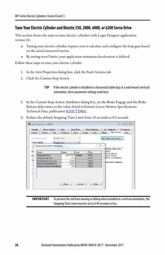
Tune Your Electric Cylinder and Kinetix 350, 2000, 6000, or 6200 Servo DriveThis section shows the steps to tune electric cylinders with Logix Designer application, version 16:
• Tuning your electric cylinder requires you to calculate and configure the loop gain based on the actual measured inertia.
• By setting travel limits, your application minimum deceleration is defined.
Follow these steps to tune your electric cylinder.
1. In the Axis Properties dialog box, click the Fault Actions tab.
2. Click Set Custom Stop Action
3. In the Custom Stop Action Attributes dialog box, set the Brake Engage and the Brake Release delay times to the values listed in Kinetix Linear Motion Specifications Technical Data, publication KNX-TD002.
4. Reduce the default Stopping Time Limit from 10 seconds to 0.5 seconds
TIP If the electric cylinder is installed in a horizontal (table top) or a wall mount (vertical) orientation, these parameter settings work best.
IMPORTANT To prevent the rod from moving or falling when installed in a vertical orientation, the Stopping Time Limit must be set to 0.99 seconds or less.
26 Rockwell Automation Publication MPAR-IN001E-EN-P - November 2017
MP-Series Electric Cylinders (Series B and C)
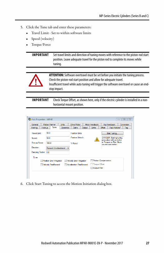
5. Click the Tune tab and enter these parameters: • Travel Limit - Set to within software limits• Speed (velocity)• Torque/Force
6. Click Start Tuning to access the Motion Initiation dialog box.
IMPORTANT Set travel limits and direction of tuning moves with reference to the piston-rod start position. Leave adequate travel for the piston rod to complete its moves while tuning.
ATTENTION: Software overtravel must be set before you initiate the tuning process. Check the piston-rod start position and allow for adequate travel.Insufficient travel while auto tuning will trigger the software overtravel or cause an end-stop impact.
IMPORTANT Check Torque Offset, as shown here, only if the electric cylinder is installed in a non-horizontal mount position.
Rockwell Automation Publication MPAR-IN001E-EN-P - November 2017 27

MP-Series Electric Cylinders (Series B and C)
7. To begin tuning the electric cylinder, click Yes.
Tuning is complete when the Tune Servo dialog box opens.
8. To exit Tuning, click OK.
The Tune Results dialog box is displayed.
9. If you are satisfied with the tuning results, click OK.
ATTENTION: Motion occurs immediately after clicking Yes.
28 Rockwell Automation Publication MPAR-IN001E-EN-P - November 2017
MP-Series Electric Cylinders (Series B and C)
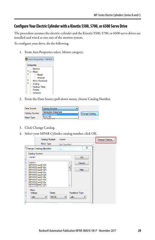
Configure Your Electric Cylinder with a Kinetix 5500, 5700, or 6500 Servo DriveThe procedure assumes the electric-cylinder and the Kinetix 5500, 5700, or 6500 servo drives are installed and wired as one axis of the motion system.
To configure your drive, do the following.
1. From Axis Properties select, Motor category.
2. From the Data Source pull-down menu, choose Catalog Number.
3. Click Change Catalog.
4. Select your MPAR Cylinder catalog number, click OK.
Rockwell Automation Publication MPAR-IN001E-EN-P - November 2017 29

MP-Series Electric Cylinders (Series B and C)
5. Click Apply.
6. From Axis Properties, select Scaling category.
7. Under Scaling, enter mm (millimeters) for Units.
ATTENTION: Incorrect parameter settings can result in uncontrolled motion that can damage to the electric cylinder. If you initiate a motion command on an electric cylinder with an incorrect Position mode, you can damage to the electric cylinder and the application in which it is installed.
30 Rockwell Automation Publication MPAR-IN001E-EN-P - November 2017

MP-Series Electric Cylinders (Series B and C)
Tune You Electric Cylinder with a Kinetix 6500, 5500 or 5700 Servo Drive
1. From Axis Properties, select Autotune.
2. Under Tune Control Loop by Measuring Load Characteristics, choose the following from the pull-down menus.a. Application Type, choose Basic.b. Loop Response, choose Medium.c. Load Coupling, choose Rigid.
3. Check Measure Inertia by using Tune Profile.
4. Click Motor with Load or Uncouple Motor, which ever applies.
5. Enter the following values.
See Kinetix Linear Motion Specifications Technical Data, publication KNX-TD002 for cylinder travel length and rated speed.
Parameter Value
Travel Limit A value less than the cylinder travel length.
Speed A speed less than the cylinder rated speed.
Torque 100
Rockwell Automation Publication MPAR-IN001E-EN-P - November 2017 31

MP-Series Electric Cylinders (Series B and C)
6. From Direction pull-down menu, select Forward Bi-directional.
7. To Perform Tune, click Start.
Wait for autotune to complete.
8. To apply values, click Accept Tune Values.
Configure Your Electric Cylinders with Ultraware SoftwareThese steps assume that an electric cylinder and an Ultra3000 drive are installed and wired as one axis of a motion system.
For help using Ultraware software as it applies to how to configure your electric cylinder, refer to Additional Resources on page 45. This procedure assumes that you are familiar with Ultraware software.
1. Connect a serial cable, catalog number 2090-DAPC-D09xx, to the CN3 connector on your Ultra3000 drive.
2. Apply AC input power to the Ultra3000 drive.
When communication with the Ultra3000 drive is established, the Ultra3000 Motor Database dialog box opens.
3. Click Cancel.
32 Rockwell Automation Publication MPAR-IN001E-EN-P - November 2017
MP-Series Electric Cylinders (Series B and C)
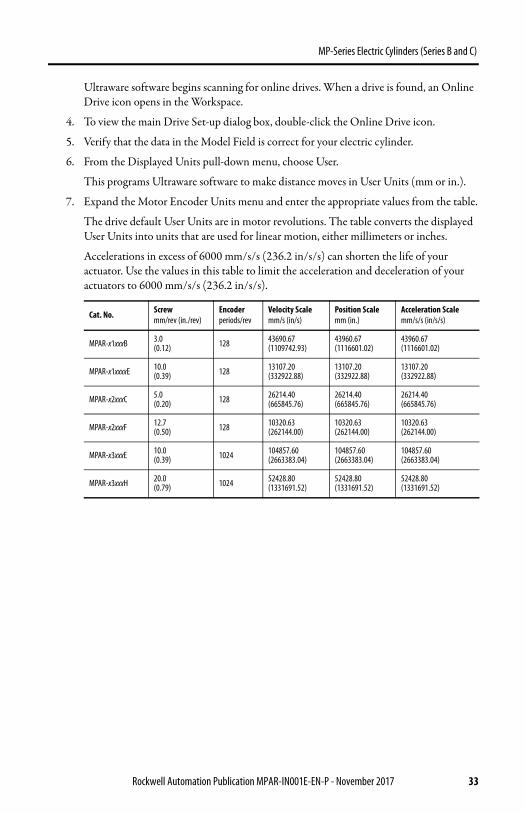
Ultraware software begins scanning for online drives. When a drive is found, an Online Drive icon opens in the Workspace.
4. To view the main Drive Set-up dialog box, double-click the Online Drive icon.
5. Verify that the data in the Model Field is correct for your electric cylinder.
6. From the Displayed Units pull-down menu, choose User.
This programs Ultraware software to make distance moves in User Units (mm or in.).
7. Expand the Motor Encoder Units menu and enter the appropriate values from the table.
The drive default User Units are in motor revolutions. The table converts the displayed User Units into units that are used for linear motion, either millimeters or inches.
Accelerations in excess of 6000 mm/s/s (236.2 in/s/s) can shorten the life of your actuator. Use the values in this table to limit the acceleration and deceleration of your actuators to 6000 mm/s/s (236.2 in/s/s).
Cat. No. Screwmm/rev (in./rev)
Encoder periods/rev
Velocity Scalemm/s (in/s)
Position Scalemm (in.)
Acceleration Scalemm/s/s (in/s/s)
MPAR-x1xxxB 3.0(0.12) 128 43690.67
(1109742.93)43960.67(1116601.02)
43960.67(1116601.02)
MPAR-x1xxxxE 10.0(0.39) 128 13107.20
(332922.88)13107.20(332922.88)
13107.20(332922.88)
MPAR-x2xxxC 5.0(0.20) 128 26214.40
(665845.76)26214.40(665845.76)
26214.40(665845.76)
MPAR-x2xxxF 12.7(0.50) 128 10320.63
(262144.00)10320.63(262144.00)
10320.63(262144.00)
MPAR-x3xxxE 10.0(0.39) 1024 104857.60
(2663383.04)104857.60(2663383.04)
104857.60(2663383.04)
MPAR-x3xxxH 20.0(0.79) 1024 52428.80
(1331691.52)52428.80(1331691.52)
52428.80(1331691.52)
Rockwell Automation Publication MPAR-IN001E-EN-P - November 2017 33
MP-Series Electric Cylinders (Series B and C)
Configure the Kinetix 300 Drive for Electric Cylinders These steps assume that an electric cylinder and the Kinetix 300 drive are installed and wired as one axis of a motion system.
For help using the Kinetix 300 drive as it applies to how to configure your electric cylinder, refer to Additional Resources on page 45. This procedure assumes that you are familiar with the Kinetix 300 drive.
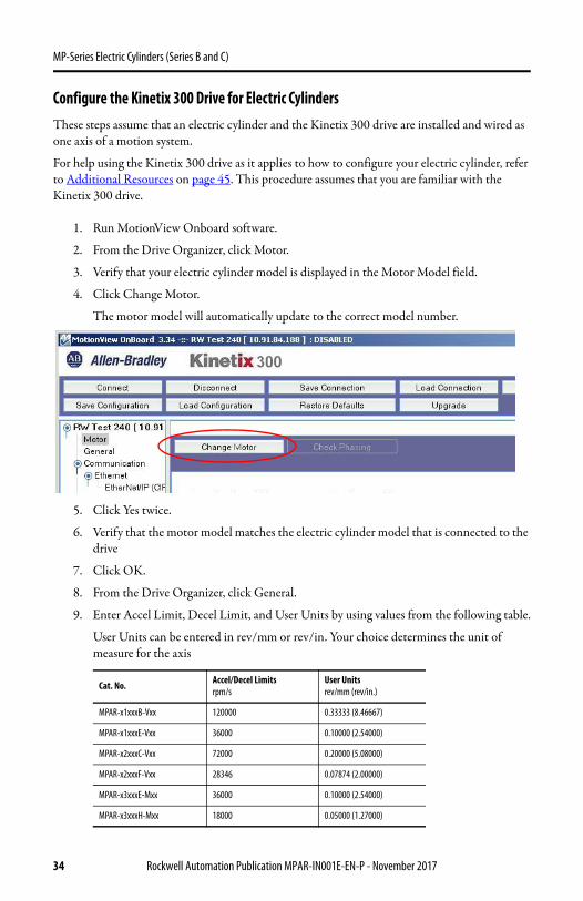
1. Run MotionView Onboard software.
2. From the Drive Organizer, click Motor.
3. Verify that your electric cylinder model is displayed in the Motor Model field.
4. Click Change Motor.
The motor model will automatically update to the correct model number.
5. Click Yes twice.
6. Verify that the motor model matches the electric cylinder model that is connected to the drive
7. Click OK.
8. From the Drive Organizer, click General.
9. Enter Accel Limit, Decel Limit, and User Units by using values from the following table.
User Units can be entered in rev/mm or rev/in. Your choice determines the unit of measure for the axis
Cat. No. Accel/Decel Limits rpm/s
User Units rev/mm (rev/in.)
MPAR-x1xxxB-Vxx 120000 0.33333 (8.46667)
MPAR-x1xxxE-Vxx 36000 0.10000 (2.54000)
MPAR-x2xxxC-Vxx 72000 0.20000 (5.08000)
MPAR-x2xxxF-Vxx 28346 0.07874 (2.00000)
MPAR-x3xxxE-Mxx 36000 0.10000 (2.54000)
MPAR-x3xxxH-Mxx 18000 0.05000 (1.27000)
34 Rockwell Automation Publication MPAR-IN001E-EN-P - November 2017

MP-Series Electric Cylinders (Series B and C)
10. From the Drive Organizer, click Homing.
11. Enter values from the following table.
These values are recommended; your application can require different values.
12. Select recommend homing method ID = 33, Home to marker, Reverse
13. Set overtravel limits according to the maximum speed of the servo drive system and the payload of the application
Parameter Metric English
Home Accel/Decel 10.0000 mm/s² 0.3937 in/s²
Home Offset 0.0000 mm 0.0000 in.
Home Velocity Fast 10.0000 mm/s 0.3937 in/s
Home Velocity Slow 10.0000 mm/s 0.3937 in/s
Home Switch Input B1
IMPORTANT Set travel limits and direction of tuning moves with reference to piston rod start position. Leave adequate travel for the piston rod to complete its moves while tuning.
ATTENTION: Software overtravel must be set before you initiate the tuning process. Check the starting position of the piston rod and allow for adequate travel. Insufficient travel while auto tuning will cause the software overtravel to trigger an end-stop impact.
ATTENTION: Take care not to exceed the physical travel limits of the electric cylinder. If you do, the electric cylinder can reach the mechanical end of stroke. An impact at the mechanical end-of-stroke can physically damage the screw and internal components of the electric cylinder.
Rockwell Automation Publication MPAR-IN001E-EN-P - November 2017 35

MP-Series Electric Cylinders (Series B and C)
You can determine the deceleration distance before the piston rod contacts the end of travel. The distance is based on the deceleration rate of the load, and the available peak force from the motor/ballscrew combination. Use the Motion Analyzer software to calculate the minimum deceleration distance at the maximum speed of your application.
Tune Your Electric Cylinder with MotionView OnBoard Software
1. From the Drive Organizer, select General.
2. From the Drive Mode pull-down menu, choose Autotune.
3. Enable the motor.
4. From the Drive Organizer, select Dynamics.
5. Click Autotune.
The Autotune dialog box opens with the default set to Velocity Tuning.
6. Check Velocity Tuning or Position Tuning or both.
7. Follow the instructions in the dialog box.
IMPORTANT A positive-direction move command denotes a rod extend operation, a negative-direction move command denotes a retract operation.
36 Rockwell Automation Publication MPAR-IN001E-EN-P - November 2017
MP-Series Electric Cylinders (Series B and C)
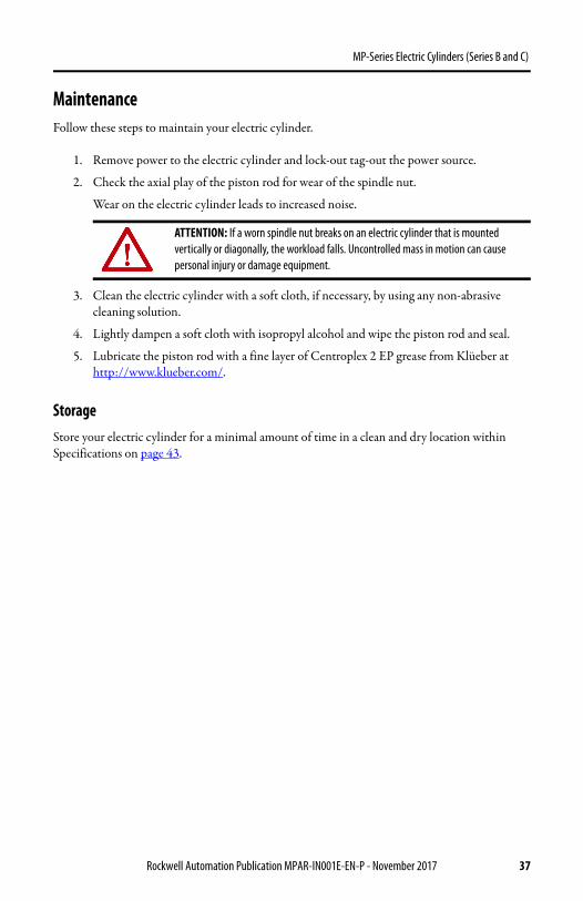
MaintenanceFollow these steps to maintain your electric cylinder.
1. Remove power to the electric cylinder and lock-out tag-out the power source.
2. Check the axial play of the piston rod for wear of the spindle nut.
Wear on the electric cylinder leads to increased noise.
3. Clean the electric cylinder with a soft cloth, if necessary, by using any non-abrasive cleaning solution.
4. Lightly dampen a soft cloth with isopropyl alcohol and wipe the piston rod and seal.
5. Lubricate the piston rod with a fine layer of Centroplex 2 EP grease from Klüeber at http://www.klueber.com/.
StorageStore your electric cylinder for a minimal amount of time in a clean and dry location within Specifications on page 43.
ATTENTION: If a worn spindle nut breaks on an electric cylinder that is mounted vertically or diagonally, the workload falls. Uncontrolled mass in motion can cause personal injury or damage equipment.
Rockwell Automation Publication MPAR-IN001E-EN-P - November 2017 37

MP-Series Electric Cylinders (Series B and C)
TroubleshootingThis table describes some possible anomalies and steps you can take to correct them.
Troubleshooting
Description Possible Cause Corrective Action
Axial play too large. Wear.Replace actuator cylinder.
Send to Rockwell Automation for repair.
Squeaking noises or vibrations.
Distortions.
Check that the electric cylinder is free of stress and evenly supported ≤ 0.2 mm (0.008 in.).
Lubricate piston rod. See Maintenance on page 37.
Modify positioning speed.
Needs tuning. Modify control parameters.
Running noises of the spindle support (with strokes 300 mm (11.81 in.) and high positioning speeds).
Normal, no impairment of function.
Piston rod does not move.
Jamming in mechanical end position, after traveling at excessive speed or into end position.
Loosen jamming manually.1. Switch off power supply.2. Remove motor and coupling housing.3. Turn drive shaft.
Reduce speed for reference travel.
Provide software end positions, at least 0.25 mm (0.01 in.) from the mechanical end positions (stops).
Load is too large.
Reduce load mass.
Reduce positioning speed.
Return for repairs.
Ambient temperature too low (increased breakaway torque in initial run due to increased viscosity of the lubricants in the spindle system).
Reduce load mass.
Reduce positioning speed.
If necessary, allow higher current with servo motors (see operating instructions for the motor).
Increase ambient temperature.
No response from electric cylinder.
Controller/drive not enable. Enable controller/drive.
Controller/drive faulted. Reset the controller/drive.
Improper/failed wiring. Check the wiring.
38 Rockwell Automation Publication MPAR-IN001E-EN-P - November 2017

MP-Series Electric Cylinders (Series B and C)
Electric cylinder is enabled but not operating or is operating erratically.
Feedback cable can be damaged. Test the feedback cable.
Feedback wiring can be incorrect. Verify correct feedback wiring.
Electric cylinder is operating but is not up to rated speeds/forces.
Motor phases are wired incorrectly or in incorrect order. Verify correct motor power wiring.
Drive can be improperly tuned. Check gain settings.
Drive can be configured improperly for electric cylinder used.
Check amplifier setting for number of poles, voltage, current, resistance, inductance, inertia, and other motor settings.
Actuator cannot move load.
Force is too large for the capacity of the electric cylinder or too much friction is present.
Verify force requirements.
Misalignment of piston rod to load. Verify load alignment.
Drive has too low of a current capacity or is limited to too low of a current capacity.
Verify correct amplifier and settings.
Electric cylinder moves or vibrates when piston rod is in motion.
Loose mounting. Check actuator mounting.
Drive is improperly tuned- wrong gain setting. Tune amplifier.
Actuator is overheating.
Duty cycle is higher than actuator rating. Verify load forces and electric cylinder rating.
Actuator is being operated outside of continuous rating.
Adjust operation to be within continuous operation rating.
Drive is poorly tuned and excessive current to be applied to motor. Check gain settings.
Troubleshooting (Continued)
Description Possible Cause Corrective Action
Rockwell Automation Publication MPAR-IN001E-EN-P - November 2017 39

MP-Series Electric Cylinders (Series B and C)
AccessoriesThe following diagram and tables show the available accessories and their weights. See the Kinetix Motion Control Selection Guide, publication GMC-SG001, for dimensions.
Accessories
Accessory Item
Serie
s
Fram
e Cat. No.Weight, Approxg (oz)
1 Foot mount attachment A
32 MPAR-NP622640 90 (3.17)
40 MPAR-NP622641 110 (3.53)
63 MPAR-NP622642 250 (8.82)
2 Flange mounting B
32 MPAR-NA174376 240 (8.46)
40 MPAR-NA174377 280 (9.88)
63 MPAR-NA174379 690 (24.34)
3 Trunnion flange A
32 MPAR-NA622625 190 (6.70)
40 MPAR-NA622626 450 (15.87)
63 MPAR-NA622627 1130 (39.86)
15
6
4
7
8
3
4
212
1
11
10
9
40 Rockwell Automation Publication MPAR-IN001E-EN-P - November 2017
MP-Series Electric Cylinders (Series B and C)
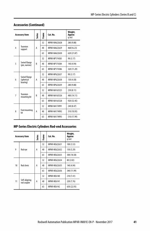
4 Trunnion support A
32 MPAR-NA622628 280 (9.88)
40 MPAR-NA622629 460(16.23)
63 MPAR-NA622630 620 (21.87)
5 Swivel flange(pin, narrow) B
32 MPAR-NP174383 90 (3.17)
40 MPAR-NP174384 140 (4.94)
63 MPAR-NP174386 320 (11.29)
6Swivel flange(spherical bearing)
A
32 MPAR-NP622637 90 (3.17)
40 MPAR-NP622638 130 (4.58)
63 MPAR-NP622639 280 (9.88)
7 Trunnion mounting kit B
32 MPAR-NA163525 230 (8.11)
40 MPAR-NA163526 400 (14.11)
63 MPAR-NA163528 920 (32.45)
8 Foot mounting kit A
32 MPAR-NA174991 240 (8.47)
40 MPAR-NA174992 310 (10.93)
63 MPAR-NA174993 510 (17.99)
MP-Series Electric Cylinders Rod-end Accessories
Accessory Item
Serie
s
Fram
e Cat. No.Weight, Approxg (oz)
9 Rod eye A
32 MPAR-NE622631 100 (3.53)
40 MPAR-NE622632 150 (5.29)
63 MPAR-NE622633 300 (10.58)
10 Rod clevis A
32 MPAR-NE622634 80 (2.82)
40 MPAR-NE622635 140 (4.94)
63 MPAR-NE622636 340 (11.99)
11 Self-aligning rod coupler A
32 MPAR-NE6140 210 (7.41)
40 MPAR-NE6141 220 (7.76)
63 MPAR-NE6142 650 (22.93)
Accessories (Continued)
Accessory ItemSe
ries
Fram
e Cat. No.Weight, Approxg (oz)
Rockwell Automation Publication MPAR-IN001E-EN-P - November 2017 41

MP-Series Electric Cylinders (Series B and C)
MP-Series Electric Cylinders Rod Guide (Item 12) Accessories
Cat. No.
Serie
s
Fram
e Stroke Lengthmm (in.)
Weight, Approxkg (lb)
MPAR-NE34494
A
32
100 (3.9) 1.7 (3.75)
MPAR-NE34496 200 (7.9) 1.9 (4.19)
MPAR-NE34497 320 (12.6) 2.1 (4.63)
MPAR-NE150290 400 (15.7) 2.3 (5.07)
MPAR-NE34500
40
100 (3.9) 2.7 (5.95)
MPAR-NE34502 200 (7.9) 3.0 (6.61)
MPAR-NE34504 320 (12.6) 3.4 (7.50)
MPAR-NE150291 400 (15.7) 3.7 (8.16)
MPAR-NE34505 500 (19.7) 4.0 (8.82)
MPAR-NE34514
63
100 (3.9) 5.9 (13.01)
MPAR-NE34516 200 (7.9) 6.4 (14.11)
MPAR-NE34518 320 (12.6) 7.0 (15.43)
MPAR-NE34519 400 (15.7) 7.4 (16.31)
MPAR-NE34520 500 (19.7) 7.9 (17.42)
Trunnion Mounting Kit
Cat. No.FrameSize
TorqueN•m (lb•ft)
MPAR-NA163525 32 4…5 (2.9…3.7)
MPAR-NA163526 40 8…9 (5.9…6.6)
MPAR-NA163528 63 18…20 (13.3…14.5)
42 Rockwell Automation Publication MPAR-IN001E-EN-P - November 2017

MP-Series Electric Cylinders (Series B and C)
Actuator Cylinders (Weight of Replacement Cylinder)
See the MP-Series Replacement Parts Installation Instructions, publication MPAR-IN002, for procedures to replace electric cylinder parts and to obtain other replacement part catalog numbers.
Specifications
In this section, you will find environmental specifications. For all other specifications see the Kinetix Linear Motion Specifications Technical Data, Publication KNX-TD002
Environmental Specifications
Actuator Cylinder (1)
Cat. No.
(1) Replacement actuator cylinder example, if ordering a replacement cylinder for electric cylinder catalog number MPAR-A2100C-V2A the replacement actuator cylinder is catalog number MPAR-X2100C.
Weight, Approxkg (lb)
Actuator Cylinder(1)
Cat. No.
Weight, Approxkg (lb)
Actuator Cylinder(1)
Cat. No.
Weight, Approxkg (lb)
MPAR-X1100B 1.1 (2.43) MPAR-X2100C 1.7 (3.75) MPAR-X3100E 3.8 (8.38)
MPAR-X1200B 1.4 (3.09) MPAR-X2200C 2.2 (4.85) MPAR-X3200E 4.6 (10.14)
MPAR-X1300B 1.7 (3.75) MPAR-X2300C 2.6 (5.73) MPAR-X3300E 5.4 (11.90)
MPAR-X1400B 2.1 (4.63) MPAR-X2400C 3.1 (6.83) MPAR-X3400E 6.3 (13.89)
MPAR-X1100E 1.1 (4.63) MPAR-X2600C 4.0 (8.82) MPAR-X3600E 7.9 (17.46)
MPAR-X1200E 1.4 (3.09) MPAR-X2100F 1.8 (3.97) MPAR-X3800E 9.5 (20.94)
MPAR-X1300E 1.8 (3.97) MPAR-X2200F 2.3 (5.07) MPAR-X3100H 3.8 (8.38)
MPAR-X1400E 2.1 (4.63) MPAR-X2300F 2.8 (6.17) MPAR-X3200H 4.6 (10.14)
MPAR-X2400F 3.2 (7.05) MPAR-X3300H 5.4 (11.90)
MPAR-X2600F 4.2 (9.26) MPAR-X3400H 6.3 (13.89)
MPAR-X3600H 7.9 (17.42)
MPAR-X3800H 9.5 (20.94)
Attribute Value
Temperature, ambient 0…40 °C (32…104 °F)
Temperature, storage -25…60 °C (-13…140 °F)
Relative humidity (noncondensing) 5…95%
Shock 20 g peak, 6 ms duration
Vibration 2.5 g peak @ 30…2000 Hz
Rockwell Automation Publication MPAR-IN001E-EN-P - November 2017 43

MP-Series Electric Cylinders (Series B and C)
Electric Cylinders (Weight of Cylinder with Non-brake Motor)
Electric CylinderCat. No.
Weight, Approx (1)
kg (lb)
Electric CylinderCat. No.
Weight, Approxkg (lb)
Electric CylinderCat. No.
Weight, Approxkg (lb)
MPAR-x1100B-V2A 2.6 (5.73) MPAR-x2100C-V2A 3.7 (8.16) (1) MPAR-x3100E-M2A 9.5 (20.94) (3)
MPAR-x1100B-V2B/D/E 3.5 (7.72) MPAR-x2100C-V2B/D/E 4.4 (9.70) (1) MPAR-x3100E-M2B/D/E 13.6 (29.98) (3)
MPAR-x1200B-V2A 2.9 (6.39) MPAR-x2200C-V2A 4.1 (9.04) (1) MPAR-x3200E-M2A 10.3 (22.71) (3)
MPAR-x1200B-V2B/D/E 3.8 (8.377) MPAR-x2200C-V2B/D/E 4.9 (10.80) (1) MPAR-x3200E-M2B/D/E 14.4 (31.75) (3)
MPAR-x1300B-V2A 3.2 (7.05) MPAR-x2300C-V2A 4.6 (10.14) (1) MPAR-x3300E-M2A 11.1 (24.47) (3)
MPAR-x1300B-V2B/D/E 4.1 (9.04) MPAR-x2300C-V2B/D/E 5.3 (11.68) (1) MPAR-x3300E-M2B/D/E 15.2 (33.51) (3)
MPAR-x1400B-V2A 3.5 (7.72) MPAR-x2400C-V2A 5.0 (11.02) (1) MPAR-x3400E-M2A 11.9 (26.23) (3)
MPAR-x1400B-V2B/D/E 4.5 (9.92) MPAR-x2400C-V2B/D/E 5.8 (12.79) (1) MPAR-x3400E-M2B/D/E 16.1 (35.49) (3)
MPAR-x1100E-V2A 3.0 (6.61) MPAR-x2600C-V2A 6.0 (11.02) (1) MPAR-x3600E-M2A 13.5 (29.76) (3)
MPAR-x1100E-V2B/D/E 3.8 (8.377) MPAR-x2600C-V2B/D/E 6.7 (14.77) (1) MPAR-x3600E-M2B/D/E 17.7 (39.02) (3)
MPAR-x1200E-V2A 3.3 (7.27) MPAR-x2100F-V2A 4.2 (9.26) (2) MPAR-x3800E-M2A 15.2 (33.51) (3)
MPAR-x1200E-V2B/D/E 4.1 (9.04) MPAR-x2100F-V2B/D/E 6.5 (14.33) (2) MPAR-x3800E-M2B/D/E 19.3 (42.55) (3)
MPAR-x1300E-V2A 3.6 (7.94) MPAR-x2200F-V2A 4.7 (10.36) (2) MPAR-x3100H-M2A 9.3 (20.50) (4)
MPAR-x1300E-V2B/D/E 4.5 (9.92) MPAR-x2200F-V2B/D/E 7.0 (15.43) (2) MPAR-x3100H-M2B/D/E 13.2 (29.10) (4)
MPAR-x1400E-V2A 4.0 (8.82) MPAR-x2300F-V2A 5.2 (11.46) (2) MPAR-x3200H-M2A 10.1 (22.27) (4)
MPAR-x1400E-V2B/D/E 4.8 (10.58) MPAR-x2300F-V2B/D/E 7.5 (16.53) (2) MPAR-x3200H-M2B/D/E 14.0 (30.86) (4)
MPAR-x2400F-V2A 5.6 (12.34) (2) MPAR-x3300H-M2A 10.9 (24.03) (4)
MPAR-x2400F-V2B/D/E 7.9 (17.42) (2) MPAR-x3300H-M2B/D/E 14.8 (32.63) (4)
MPAR-x2600F-V2A 6.6 (14.55) (2) MPAR-x3400H-M2A 11.7 (25.79) (4)
MPAR-x2600F-V2B/D/E 8.9 (19.62) (2) MPAR-x3400H-M2B/D/E 15.7 (34.61) (4)
MPAR-x3600H-M2A 13.4 (29.54) (4)
MPAR-x3600H-M2B/D/E 17.3 (38.14) (4)
MPAR-x3800H-M2A 15.0 (33.07) (4)
MPAR-x3800H-M2B/D/E 18.9 (41.67) (4)
(1) If you are ordering an MPAR-x1xxxx-V4x or MPAR-x2xxxC-V4x electric cylinder with brake, add 0.2 kg (0.4 lb).(2) If you are ordering an MPAR-x2xxxF-V4x electric cylinder with brake, add 0.4 kg (0.9 lb).(3) If you are ordering an MPAR-x3xxxE-V4x electric cylinder with brake, add 1.0 kg (2.2 lb).(4) If you are ordering an MPAR-x3xxxH-M4x electric cylinder with brake, add 1.7 kg (3.7 lb).
44 Rockwell Automation Publication MPAR-IN001E-EN-P - November 2017
MP-Series Electric Cylinders (Series B and C)
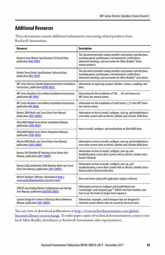
Additional Resources These documents contain additional information concerning related products from Rockwell Automation.
You can view or download publications at http://www.rockwellautomation.com/global/literature-library/overview.page. To order paper copies of technical documentation, contact your local Allen-Bradley distributor or Rockwell Automation sales representative.
Resource Description
Kinetix Linear Motion Specifications Technical Data, publication KNX-TD002
This document provides catalog numbers and product specifications, including power, performance, environmental, certifications, dimension drawings, and accessories for Allen-Bradley® linear motion products.
Kinetix Servo Drives Specifications Technical Data, publication KNX-TD003
This document provides catalog numbers and product specifications, including power, performance, environmental, certifications, dimension drawings, and accessories for Allen-Bradley® servo drives.
MP-Series Electric Cylinder Replacement Parts Installation Instructions, publication MPAR-IN002
Information on replacing actuator cylinders, motors, couplings, and belts.
MP-Series Brushless Servo Motor Installation Instructions, publication MP-IN001
Information for the installation of 100…165 mm frame size MP-Series low-inertia motors.
MP-Series Brushless Servo Motor Installation Instructions, publication MP-IN006
Information for the installation of small frame (<75 mm) MP-Series low-inertia motors.
Kinetix 2000 Multi-axis Servo Drive User Manual, publication 2093-UM001
Information on how to install, configure, start up, and troubleshoot a servo drive system with an electric cylinder and a Kinetix 2000 drive.
Ultra3000 Digital Servo Drives Installation Manual, publication 2098-IN003
How to install, configure, and troubleshoot an Ultra3000 drive.Ultra3000 Digital Servo Drives Integration Manual, publication 2098-IN005
Kinetix 6000 Multi-axis Servo Drives User Manual, publication 2094-UM001
Information on how to install, configure, start up, and troubleshoot a servo drive system with an electric cylinder and a Kinetix 6000 drive.
Kinetix 300 EtherNet/IP Indexing Servo Drives User Manual, publication 2097-UM001
Information on how to install, configure, start up, and troubleshooting a servo drive system with an electric cylinder and a Kinetix 300 drive.
Kinetix 6200 and Kinetix 6500 Modular Multi-axis Servo Drive User Manual, publication 2094-UM002
Information on how to install, configure, start up, and troubleshooting a servo drive system with an electric cylinders and a Kinetix 6200 or Kinetix 6500 drive.
Motion Analyzer Software, download at http://www.rockwellautomation.com/en/e-tools Drive and motor sizing with application analysis software.
SERCOS and Analog Motion Configuration and Startup User Manual, publication MOTION-UM001
Information on how to configure and troubleshoot your ControlLogix® and CompactLogix™ SERCOS interface modules, and how to use the home to torque-level sequence.
System Design for Control of Electrical Noise Reference Manual, publication GMC-RM001
Information, examples, and techniques that are designed to minimize system failures that are caused by electrical noise.
Rockwell Automation Publication MPAR-IN001E-EN-P - November 2017 45

MP-Series Electric Cylinders (Series B and C)
Notes:
46 Rockwell Automation Publication MPAR-IN001E-EN-P - November 2017

MP-Series Electric Cylinders (Series B and C)
Notes:
Rockwell Automation Publication MPAR-IN001E-EN-P - November 2017 47
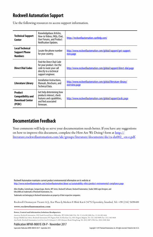
Rockwell Automation SupportUse the following resources to access support information.
Documentation FeedbackYour comments will help us serve your documentation needs better. If you have any suggestions on how to improve this document, complete the How Are We Doing? form at http://literature.rockwellautomation.com/idc/groups/literature/documents/du/ra-du002_-en-e.pdf.
Technical Support Center
Knowledgebase Articles, How-to Videos, FAQs, Chat, User Forums, and Product Notification Updates.
https://rockwellautomation.custhelp.com/
Local Technical Support Phone Numbers
Locate the phone number for your country.
http://www.rockwellautomation.com/global/support/get-support-now.page
Direct Dial Codes
Find the Direct Dial Code for your product. Use the code to route your call directly to a technical support engineer.
http://www.rockwellautomation.com/global/support/direct-dial.page
Literature LibraryInstallation Instructions, Manuals, Brochures, and Technical Data.
http://www.rockwellautomation.com/global/literature-library/overview.page
Product Compatibility and Download Center (PCDC)
Get help determining how products interact, check features and capabilities, and find associated firmware.
http://www.rockwellautomation.com/global/support/pcdc.page
Allen-Bradley, ControlLogix, CompactLogix, Kinetix, MP-Series, Rockwell Software, Rockwell Automation, Studio 5000 Logix Designer, andUltra3000 are trademarks of Rockwell Automation, Inc.
Trademarks not belonging to Rockwell Automation are property of their respective companies.
Rockwell Otomasyon Ticaret A.Ş., Kar Plaza İş Merkezi E Blok Kat:6 34752 İçerenköy, İstanbul, Tel: +90 (216) 5698400
Rockwell Automation maintains current product environmental information on its website athttp://www.rockwellautomation.com/rockwellautomation/about-us/sustainability-ethics/product-environmental-compliance.page.
Publication MPAR-IN001E-EN-P - November 2017Supersedes Publication MPAR-IN001D-EN-P - September 2012 Copyright © 2017 Rockwell Automation, Inc. All rights reserved. Printed in the U.S.A.