moving towards a world without halon volume 2halon.org/pdfs/kidde.pdfcylinder size mount type part...
TRANSCRIPT


firmly. Do not overtighten.3. Using the 4.375" diameter wrench, replace the pipe adapter.4. Reconnect pneumatic tubing at the pilot release valve.5. Install safety plug on valve discharge outlet. Tighten one turn beyond hand tight.6. Follow refilling procedures as outlined in Fenwal Publication 242
FENWAL INCORPORATEDKIDDE INC._____________400 Main Street, Ashland, Massachusetts 01721(617)881-2000
Return to Table of Contents
KIDDE INC.HALON 1301 SYSTEM CONTAINERS
Component Description
Cylinder Size Mount Type Part Number
10 Lb. Horizontal/Vertical Std. 487010
20 Lb. Horizontal/Vertical Std 487020
40 Lb. Horizontal/Vertical Std 487010
70 Lb. Horizontal/Vertical Std 487070
125 Lb. Vertical Std 487125
125 Lb. Horizontal Std 487127
200 Lb. Vertical Std 487200
200 Lb. Horizontal Std 487202
350 Lb. Vertical Std 487350
350 Lb. Vertical w/LLI 487351
600 Lb. Vertical Std 487600
600 Lb. Vertical w/LLI 487601
Std. = Standard Cylinder Assembly


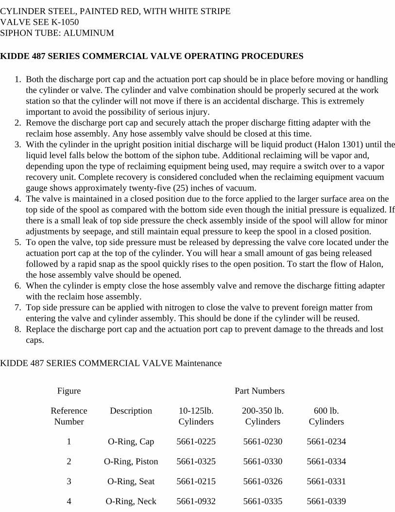
CYLINDER STEEL, PAINTED RED, WITH WHITE STRIPE VALVE SEE K-1050SIPHON TUBE: ALUMINUM
KIDDE 487 SERIES COMMERCIAL VALVE OPERATING PROCEDURES
1. Both the discharge port cap and the actuation port cap should be in place before moving or handling the cylinder or valve. The cylinder and valve combination should be properly secured at the work station so that the cylinder will not move if there is an accidental discharge. This is extremely important to avoid the possibility of serious injury.
2. Remove the discharge port cap and securely attach the proper discharge fitting adapter with the reclaim hose assembly. Any hose assembly valve should be closed at this time.
3. With the cylinder in the upright position initial discharge will be liquid product (Halon 1301) until the liquid level falls below the bottom of the siphon tube. Additional reclaiming will be vapor and, depending upon the type of reclaiming equipment being used, may require a switch over to a vapor recovery unit. Complete recovery is considered concluded when the reclaiming equipment vacuum gauge shows approximately twenty-five (25) inches of vacuum.
4. The valve is maintained in a closed position due to the force applied to the larger surface area on the top side of the spool as compared with the bottom side even though the initial pressure is equalized. If there is a small leak of top side pressure the check assembly inside of the spool will allow for minor adjustments by seepage, and still maintain equal pressure to keep the spool in a closed position.
5. To open the valve, top side pressure must be released by depressing the valve core located under the actuation port cap at the top of the cylinder. You will hear a small amount of gas being released followed by a rapid snap as the spool quickly rises to the open position. To start the flow of Halon, the hose assembly valve should be opened.
6. When the cylinder is empty close the hose assembly valve and remove the discharge fitting adapter with the reclaim hose assembly.
7. Top side pressure can be applied with nitrogen to close the valve to prevent foreign matter from entering the valve and cylinder assembly. This should be done if the cylinder will be reused.
8. Replace the discharge port cap and the actuation port cap to prevent damage to the threads and lost caps.
KIDDE 487 SERIES COMMERCIAL VALVE Maintenance
Figure Part Numbers
Reference Number
Description 10-125lb. Cylinders
200-350 lb. Cylinders
600 lb. Cylinders
1 O-Ring, Cap 5661-0225 5661-0230 5661-0234
2 O-Ring, Piston 5661-0325 5661-0330 5661-0334
3 O-Ring, Seat 5661-0215 5661-0326 5661-0331
4 O-Ring, Neck 5661-0932 5661-0335 5661-0339

depending upon the type of reclaiming equipment being used, may require a switch over to a vapor recovery unit. Complete recovery is considered concluded when the reclaiming equipment vacuum gauge shows approximately twenty-five (25) inches of vacuum.
4. The valve is maintained is a closed position due to the force applied to the larger surface area on the top side of the spool as compared with the bottom side even though the internal pressure is equalized. If there is a small leak of top side pressure the check assembly inside of the spool will allow for minor adjustments by seepage, and still maintain equal pressure to keep the spool in a closed position.
5. To open the valve, top side pressure must be released by depressing the pilot check assembly located under the actuation port cap at the top of the cylinder. This is done by attaching a lever control head as shown. Pull the safety pin and flip the lever to the open position. You will hear a small amount of gas start to release followed by a rapid snap of the piston quickly rising to the open position. A small amount of gas will continue to be released until the cylinder is empty. To start the flow of Halon, the hose assembly valve should be opened.
6. When the cylinder is empty close the hose assembly valve and remove the discharge fitting adapter with the reclaim hose assembly.
7. Close the lever control head, install the safety pin and remove the control head. The valve spring will close the valve automatically.
8. Replace the discharge port cap and the actuation port cap to prevent damage to the threads and lost caps.
360 PSI HALON 1301 CYLINDER VALVE - OBSOLETE
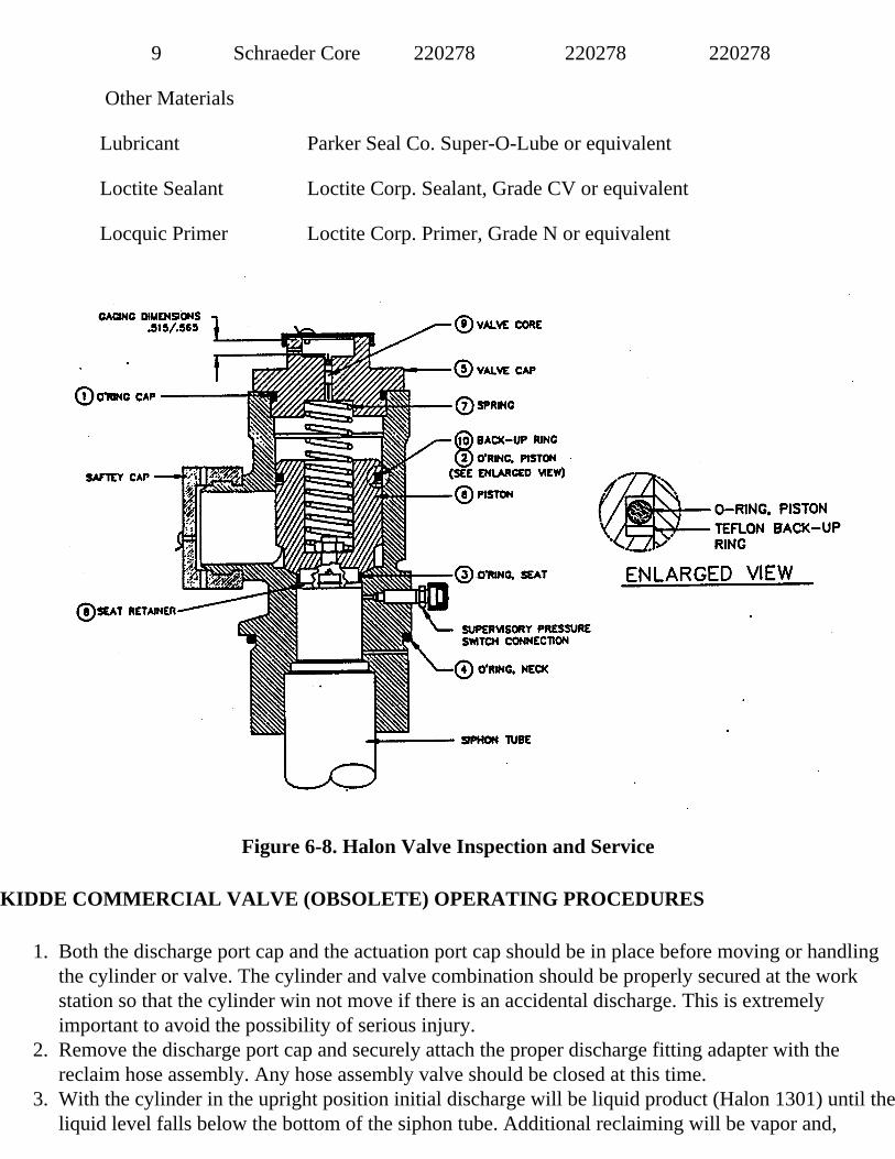
9 Schraeder Core 220278 220278 220278
Other Materials
Lubricant Parker Seal Co. Super-O-Lube or equivalent
Loctite Sealant Loctite Corp. Sealant, Grade CV or equivalent
Locquic Primer Loctite Corp. Primer, Grade N or equivalent
Figure 6-8. Halon Valve Inspection and Service
KIDDE COMMERCIAL VALVE (OBSOLETE) OPERATING PROCEDURES
1. Both the discharge port cap and the actuation port cap should be in place before moving or handling the cylinder or valve. The cylinder and valve combination should be properly secured at the work station so that the cylinder win not move if there is an accidental discharge. This is extremely important to avoid the possibility of serious injury.
2. Remove the discharge port cap and securely attach the proper discharge fitting adapter with the reclaim hose assembly. Any hose assembly valve should be closed at this time.
3. With the cylinder in the upright position initial discharge will be liquid product (Halon 1301) until the liquid level falls below the bottom of the siphon tube. Additional reclaiming will be vapor and,

MATERIALSVALVE BODY: ALUMINUMSWIVEL NUT: STEELPISTON: ALUMINUMSEAT: RUBBER
ENGINEERED SYSTEMS SUPPLEMENTAL MAINTENANCEOBSOLETE HALON 1301 EOUIPMENT
Max. Qty. From Stock
Part No. Description
SECTION C - 360 PSI HALON 1301 CYLINDER VALVE (continued)
10 258423 Valve Seat

• 56610346 O-Ring, Collar
• 56610227 O-Ring, Piston
10 56610114 O-Ring, Pilot
• 56610140 O-Ring, Discharge
• 877205 Pilot Check Assembly
5 280458 Gauge
• 258441 Gauge Guard (Aluminum Valve)
• 844881 Anti-Recoil Fitting (Brass Valve)
• 280456 Discharge Adapter(Aluminum Valve)
• 283865 Discharge Adapter (Brass Valve)
• 294341 Cylinder Label, non-U.L.
• 283873 Cylinder Label, Danger
• 283310 Cylinder Label, Care & Use
• 293425 Valve Nameplate, 360 Psi 360 PSI (Aluminum Valve)
• 296059 Valve Nameplate, 360 Psi 360 PSI (Brass Valve)
• 877378 Recharge Adapter, 360 PSI cylinder Assembly
• 897800 Weigh Scale, 360 PSI Cylinder Assembly
• 256492 Tag, Inspection Record
SECTION D - 360 PSI VALVE CROSS SECTION.

LEVER OPERATED CONTROL HEAD

1. Both the discharge port cap and the actuation port cap should be in place before moving or handling the cylinder or valve. The cylinder and valve combination should be properly secured at the work station so that the cylinder will not move if there is an accidental discharge. This is extremely important to avoid the possibility of serious injury.
2. Remove the discharge port cap and securely attach the proper discharge fitting adapter with the reclaim hose assembly. Any hose assembly valve should be closed at this time.
3. With the cylinder in the upright position initial discharge will be liquid product (Halon 1301) until the liquid level falls below the bottom of the siphon tube. Additional reclaiming will be vapor and, depending upon the type of reclaiming equipment being used, may require a switch over to a vapor recovery unit. Complete recovery is considered concluded when the reclaiming equipment vacuum gauge shows approximately twenty-five (25) inches of vacuum.
4. The valve is maintained in a closed position due to the force applied to the larger surface area on the top side of the spool as compared with the bottom side even though the internal pressure is equalized. If there is a small leak of top side pressure the check assembly inside off the spool will allow for minor adjustments by seepage, and still maintain equal pressure to keep the spool in a closed position.
5. To open the valve, top side pressure must be released by depressing the pilot check assembly located under the actuation port cap located at a position forty-five degrees (45º) to the discharge port cap at the top of the cylinder. You will hear a small amount of gas being released followed by a rapid snap as the spool quickly rises to the open position. To start the flow of Halon, the hose assembly valve should be opened.
6. When the cylinder is empty close the hose assembly valve and remove the discharge fitting adapter with the reclaim hose assembly.
7. Top side pressure can be applied with nitrogen to close the valve to prevent foreign matter from entering the valve and cylinder assembly. This should be done if the cylinder will reused.
8. Replace the discharge port cap and the actuation part cap to prevent damage to the threads and lost caps.
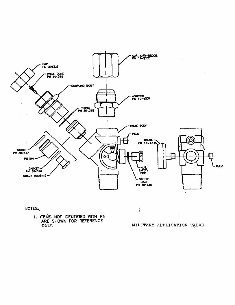
KIDDE MILITARY APPLICATION VALVE OPERATING PROCEDURES


Max. Qty.FromStock
Part No -Description
SECTION G - HALON VALVE MAINTENANCE, REPAIR AND SPARE PARTS
• 486143 Halon Valve Assembly without safety Outlet Adapter Connection
• 844336 Shipping Protection Cap NSN 5340-01-205-9936
• 283535 Valve Cap
• 844911 Pilot Check Assembly (includes pilot check, spring, filler washer
4 56610225 O-ring, Cap
• 218943 Spring
• 844912 Piston Rings(includes piston o-ring, piston back-up ring)
• 283531 Piston
• 844913 Valve retainer Assembly (includes nut, retainer, filter, snap ring, ball check, seal)

• 844579 Anti-Recoil Cap, Valve Outlet
4 56610215 O-Ring, Retainer
• 844914 Safety Disc Assembly(includes disc, washer, retainer)
• 263144 Pressure Gauge
5 56610932 O-Ring, Cylinder Neck
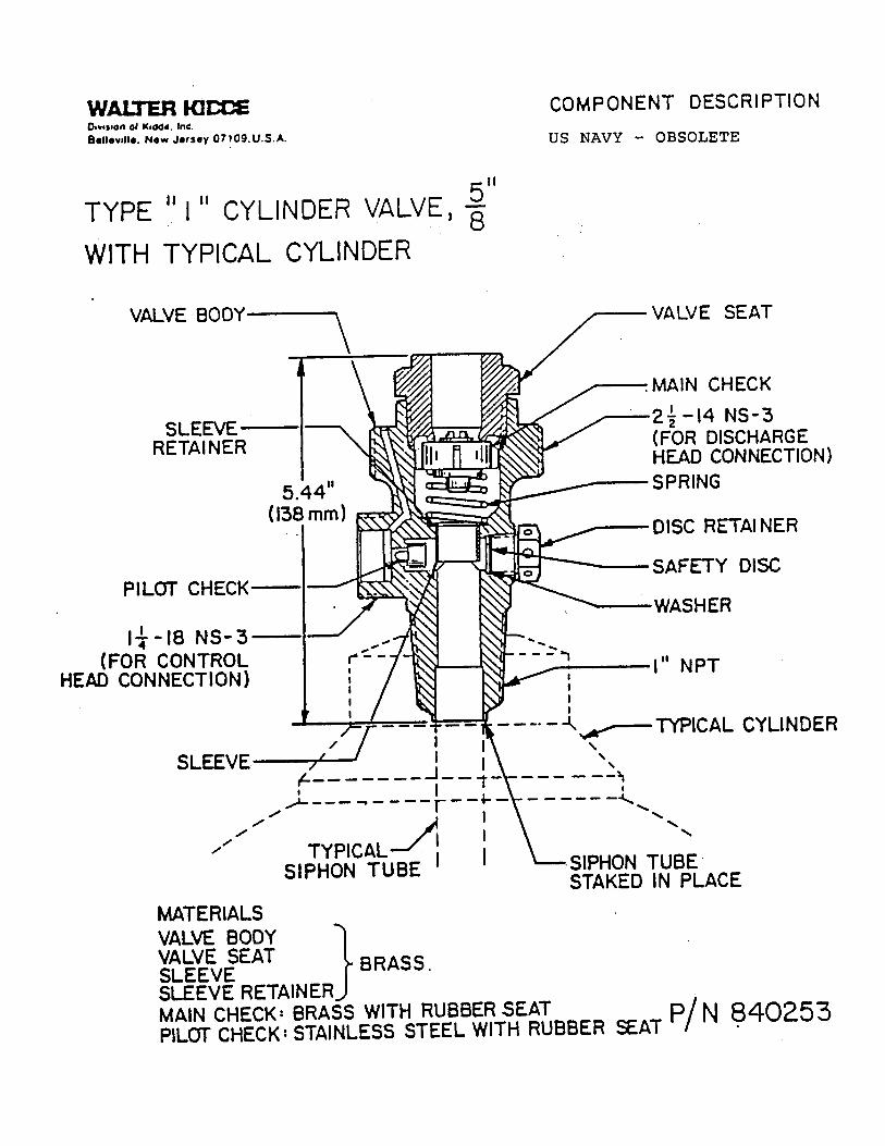
WALTER KIDDE COMPONENT DESCRIPTION
LEVEL OPERATED CONTROL HEAD

KIDDE US NAVY VALVE (OLD STYLE - WITH SAFETY OUTLET ADAPTER CONNECTION) OPERATING PROCEDURES
1. Both the discharge port cap and the actuation port cap should be in place before moving or handling the cylinder or valve. The cylinder and valve combination should be properly secured at the work station so that the cylinder will not move if there is an accidental discharge. This is extremely important to avoid the possibility of serious injury.
2. Remove the discharge port cap and securely attach the proper discharge fitting adapter with the reclaim hose assembly. Any hose assembly valve should be dosed at this time.
3. With the cylinder in the upright position initial discharge will be liquid product (Halon 1301) until the liquid level falls below the bottom of the siphon tube. Additional reclaiming will be vapor and, depending upon the type of reclaiming equipment being used, may require a switch over to a vapor recovery unit. Complete recovery is considered concluded when the reclaiming equipment vacuum gauge shows approximately twenty-five (25) inches of vacuum.
4. The valve is maintained is a closed position due to the force applied to the larger surface area on the top side of the spool as compared with the bottom side even though the internal pressure is equalized. If there is a small leak of top side pressure the check assembly inside of the spool will allow for minor adjustments by seepage, and still maintain equal pressure to keep the spool in a dosed position.
5. To open the valve, top side pressure must be released by depressing the pilot check assembly located under the actuation port cap at the top of the cylinder. This is done by attaching a lever control head as shown. Pull the safety pin and flip the lever to the open position. You will hear a small amount of gas start to release followed by a rapid snap of the piston quickly rising to the open position. A small amount of gas will continue to be released until the cylinder is empty. To start the flow of halon, the hose assembly valve should be opened.
6. When the cylinder is empty close the hose assembly valve and remove the discharge fitting adapter with the reclaim hose assembly.
7. Close the lever control head, install the safety pin and remove the control head. The valve spring will close the valve automatically.
8. Replace the discharge port cap and the actuation port cap to prevent damage to the threads and lost caps.


LEVER OPERATED CONTROL HEAD

US NAVY (OBSOLETE) VALVE OPERATING PROCEDURES
1. Both the discharge port cap and the actuation part cap should be in place before moving or handling the cylinder or valve. The cylinder and valve combination should be properly secured at the work station so that the cylinder will not move if there is an accidental discharge. This is extremely important to avoid the possibility of serious injury.
2. Remove the discharge port cap and securely attach the discharge head to the top of the valve. Securely attach the proper discharge fitting adapter with the reclaim hose to the discharge head. Any hose assembly valve should be closed at this time.
3. With the cylinder in the upright position initial discharge will be liquid product (Halon 1301) until the liquid level falls below the bottom of the siphon tube. Additional reclaiming will be vapor and, depending upon the type of reclaiming equipment being used, may require a switch over to a vapor recovery unit. Complete recovery is considered concluded when the reclaiming equipment vacuum gauge shows approximately twenty-five (25) inches of vacuum.
4. The valve is maintained is a closed position due to the force applied to the main check by the internal cylinder pressure.
5. Attach a lever control head to the control outlet (actuation port) located on the side of the valve. To open the valve, pull the safety pin and flip the lever to the open position. This will pressurize the discharge head and depress the main check. To start the flow of Halon, the hose assembly valve should be opened.
6. When the cylinder is empty close the hose assembly valve and remove the discharge fitting adapter with the reclaim hose assembly.
7. Close the lever control head, install the safety pin and remove the control head. The valve spring will close the valve automatically. Remove the discharge head.
8. Replace the discharge port cap and the actuation port cap to prevent damage to the threads and lost caps.
WALTER KIDEDivision of Kidde Inc Belleville, New Jersey 07109 U.S.A
COMPONENT DESCRIPTIONUS NAVY-OBSOLETE

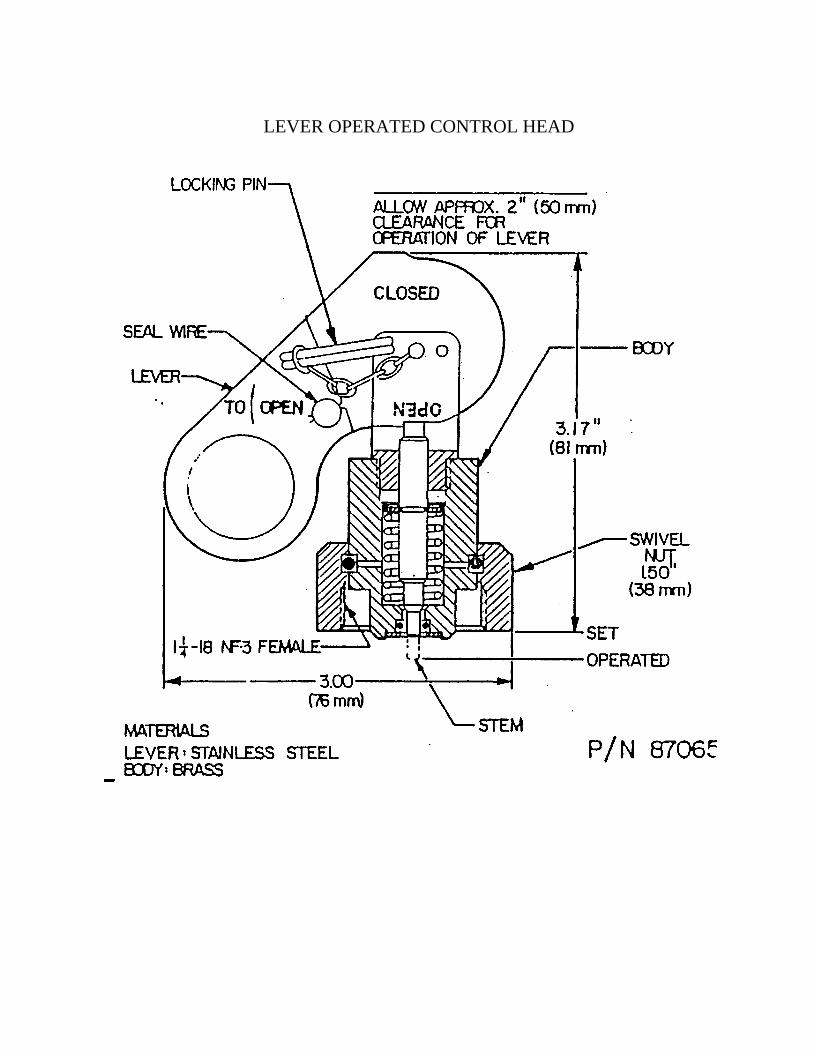
LEVER OPERATED CONTROL HEAD