“moving advancements into practice” map brief 5-1 · “moving advancements into practice”...
TRANSCRIPT
ldquoMoving Advancements into Practicerdquo
MAP Brief 5-1 Describing promising technologies that can be used now to enhance concrete paving practices
wwwcproadmaporg
OCTOBER 2010
ROAD MAP TRACK 5 Concrete Pavement Equipment Automation and Advancements
PRIMARY SOURCE Improving Concrete Overlay Construction (Iowa Highway Research Board Project TR-600) June 2010 James K Cable Cable Concrete Consultation
SECONDARY SOURCE Stringless Portland Cement Concrete Paving February 2004 James K Cable Cable Concrete Consultation
SPONSOR Federal Highway Administration Iowa Department of Transportation Iowa Highway Research Board
MORE INFORMATION Dale Harrington 515-956-2020 dharringtonsnyder-associates com
Moving Advancements into Practice (MAP) Briefs describe promising technologies that can be used now to enhance concrete paving practices MAP Brief 8-1 provides information relevant to Track 8 of the CP Road Map Long-Life Concrete Pavements
The Long-Term Plan for Concrete Pavement Research and Technology (CP Road Map) is a national research plan developed and jointly implemented by the concrete pavement stakeholder community Publications and other support services are provided by the Operations Support Group and funded by TPF-5(185)
MAP Brief 8-1 is available at httpwwwcproadmaporg publicationsMAPbrief 8-1pdf
Stringless Concrete Paving
Introduction Conventional concrete paving with a slipform paver requires the installation of a stringline and support posts adjacent to the roadway to establish the correct pavement alignment and profile The stringline adds several additional feet (6 ft +-) of required clearance to the paving envelope which is already wider than the pavement due to the tracks of the slipform paver
In addition the stringline becomes an obstacle for equipment concrete delivery trucks and finishing crews If equipment access across the stringline is required the stringline must be lowered and reset resultshying in delays and introducing the potential for errors
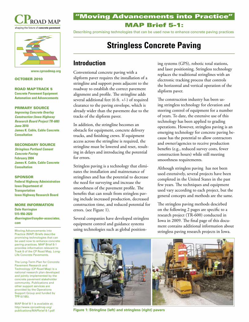
Stringless paving is a technology that elimishynates the installation and maintenance of stringlines and has the potential to decrease the need for surveying and increase the smoothness of the pavement profile The benefits that can result from stringless pavshying include increased production decreased construction time and reduced potential for errors (see Figure 1)
Several companies have developed stringless equipment control and guidance systems using technologies such as global position-
Figure 1 Stringline (left) and stringless (right) pavers
ing systems (GPS) robotic total stations and laser positioning Stringless technology replaces the traditional stringlines with an electronic tracking process that controls the horizontal and vertical operation of the slipform paver
The construction industry has been usshying stringless technology for elevation and steering control of equipment for a number of years To date the extensive use of this technology has been applied to grading operations However stringless paving is an emerging technology for concrete paving beshycause has the potential to allow contractors and owneragencies to receive production benefits (eg reduced survey costs fewer construction hours) while still meeting smoothness requirements
Although stringless paving has not been used extensively several projects have been completed in the United States in the past few years The techniques and equipment used vary according to each project but the general concepts and methods are the same
The stringless paving methods descirbed on the following 2 pages are specific to a research project (TR-600) conducted in Iowa in 2009 The final page of this docushyment contains additional information about stringless paving research projects in Iowa
CP Road MAP Brief 5-1 CP Road MAP Brief 5-1
STRINGLESS PAVING FRef Point 2
(xyz)
360deg Prism (Back)for Concrete Overlay Over Asphalt TR-600 Research Project
survey data of the existing surface (Figure 3) to develop and build a database Step two is to design the
transferring the computer model to the paving machine and utilizing a non-contact XYZ guidance system
Roadway Surface Mapping In order to map the existing roadway surface an all-terrain vehicle (ATV) was used
25-foot intervals along the pavement edges wheel paths lane quarter points and centerline It needs to be noted that GPS accuracy is good vertically to only one inch so to obtain the proper accuracy in the Z coordinate the ATV had to be augmented with a laser system An alternate to the ATV is to survey the existing pavement with a total station The data collected was used to produce a 3D plot of the pavement surface utilizing readily available CADD software Data was streamed from both units to a central computer for storage using the Iowa real time network (RTN) system and its ability to correct for location and elevation
The ground reference system should contain reference points with known XYZ values spaced approxishymately 250 feet apart and on alternating sides of the roadway The Z value should be obtained through electronic three-wire leveling just in advance of the construction to verify the overlay design assump-
The data management method involved the use NMEA string that provided XYZ coordinates of eain latitude longitude and elevation The data watranslated into state plane coordinates and elevat
of a ch point s then ion from
Ref Point 2
250rsquo +-
25rsquo +- Spacing or shorter
ATV with GPS Unit Ref Point 3
4rsquo
Ref Point 1 (4rsquo rod with plate (TYP)) Center Line
Wheel Line 14 Point
Edge Wheel Line
Figure 3 GPS Mapping of Existing Surface Pavement (xyz)
with pilot car control
Single lane under
construction
Electronic Stingline
Robotic Total Station (TS)
Concrete Overlay
360deg Prism (Front) Other Reference Points and Total Stations
Ref Point 1 (xyz)
Slope sensor
Ref Point 3 (xyz)
Robotic Total Station (TS)
igure 4 Stringless Paving Operation
Slipform Paver Machine Controls The 3D model provided the design surface of the proposed overlay The stringless paving method selected utilized multiple robotic total stations with prisms mounted on the paving machine Vertical control reference points were established earlier at 250-foot intervals on alternating sides of the roadway This kept the paving equipment crews and terrain from interfering with the line of sight between the paving machine and reference control points In order for the robotic total station to establish correct XYZ coordinates the station needed to have a triangulation system which required a clear line-of-sight to at least three
electronichydraulic controls
During stringless paving operation two total stations continually provide independent coordinate information to the paving machine Prisms mounted
back to the total stations giving them itrsquos X Y Z position This information is then transmitted via radio signal from the total stations to the computer on the paving machine The paving machinecomputer processes itrsquos exact position in relation to a computer model of the new pavement The onboard computer then adjusts the elevation of the machine on each of the four corners of the pan to achieve the correct pavement thickness crossfall and mainfall
Robotic Total Station (TS)
HEADING
360deg Prism (Front) 360deg Prism (Back)
Screen
Radios
Back SensorFront Sensor
Ref Point 3 (xyz)
MAINFALL
Paving Machine Needs position (north east amp height) CROSSFALL along with attitude (heading crossfall amp mainfall Heading the horizontal control calculated from GPS surface mapping Crossfall cross slope control monitored by sensor Mainfall forward and back slope control monitored by sensor
Figure 5 PavingMachine Control
CP Road MAP Brief 5-1
Research Conducted To examine the practicality of stringless paving with slipform pavers the National Concrete Pavement Technology Center and the Federal Highway Administration (FHWA) comshypleted field research in 2003 on two stringless paving projects in Washington County Iowa As part of these projects a research team monitored the guidance and elevation conshyformance to the original pavement design The evaluation included guidance from GPS and laser technology
Due to the speed of paving and the rapid changes in terrain the laser technology was abandoned for the projects Total control of the guidance and elevation controls on the slip-form paver were moved from stringline to GPS The evaluashytion was a success and the research team concluded that the GPS control proved to provide excellent x y guidance for the slipform paver However GPS vertical control did not allow for smoothness incentives
In 2009 the Iowa Highway Research Board and FHWA conducted research on four concrete overlay projects in Iowa to evaluate overlay construction techniques and methods Due to improved stringless paving technology this project included additional research that evaluated stringless paving on two of the four concrete overlay projects (US 65 in Worth County and V18 in Poweshiek County)
The goals of the 2009 research were to develop ways to estabshylish profile grades and machine control before or immediately after contract letting to evaluate machine control systems to minimize paving train widths and to meet or exceed smoothness requirements
Conclusions
The following sections describe the results of the 2009 reshysearch projects on stringless concrete paving in Iowa
Roadway Surface Mapping
bull The results of roadway mapping indicate that current ldquooff-the-shelf rdquo GPS technology does not provide adequate vertical (z) accuracy for mapping the pavement surface when measured with a rapidly moving device Slow movshying (lt5mph) GPS data collection and other proprietary software and systems do have the potential for mapping the pavement surface with an (x y) accuracy adequate for paving machine control
bull The vertical (z) coordinates of the existing surface can be obtained by laser augmentation on the same all-terrain utility vehicles that capture the GPS (x y) coordinates The alternative is to survey the surface with total stations
bull Profile mapping is possible with 3D computer software such as AutoCAD and MicroStation for the surface profiles of the existing road surface and the design model of the overlay surface This information can be used to develop cross-sections check minimum overlay depths and calcushylate concrete quantities for theoretical yield purposes
Slipform Paver Machine Control
bull The stringless paving control system performed to expectashytions in line grade and cross-slope control to match the designer model for the surface of the finished pavement overlay on each of the two test projects
bull To meet the smoothness requirements for incentive pay it is recommended that model and machine control elevations be developed in the 001-005 ft plus or minus range
bull Regardless of the brand modern slipform pavers that have recent constant-flow hydraulic systems and up-to-date elecshytronic controls can be outfitted with the stringless paving system used in this project from Leica Inc
bull Success of the stringless system rests on the slipform paver controls and the ability to set very tight vertical control for the guidance system on the ground
bull The control system will replicate what the designer puts into the final surface model
bull The Leica system used in this research performed equally well on one- and two-lane paving situations In one-lane situations the outer edge is controlled by the model on the second pass and the centerline of the first pass is ldquolockedrdquo to existing elevations of the first pass
bull Designer knowledge of the existing surface alignment and surface elevations is critical to development of the final design model
bull GPS- and GPSlaser-controlled slipform operations do exist but were not evaluated in this research due to the decisions made by contractors in control equipment selection
bull Sensor selection for the paving equipment should be left to the discretion of the contractor based on the tolerances established in the contract documents for the concrete depth and quantity
For More Information To find out more about stringless concrete paving impleshymentation and demonstration projects contact the National Concrete Pavement Technology Center 515-294-8103 dfwagneriastateedu
Neither CP Road Map participants or sponsors nor the Federal Highway Administration assumes liability for the information contained in this publication or enshydorses products or manufacturers mentioned herein