mounting and operating instructions - avv...
TRANSCRIPT

Mounting and Operating Instructions
EURO ZB.1EURO US.1
Target group, part 1: Qualified electrician acc. to DIN VDE 0105, part 1Target group, part 2: Electrical instructed persons
Mounting and Operating ManualCentral Battery System EURO ZB.1
2 CEAG Notlichtsysteme GmbH
Table of contents
Part 11 Important Notes 4
2 Product Description 5
3 Technical Data 11
4 Batteries for Emergency Power Supply 164.1 Tending and Checking Batteries 17
5 Modules Functioning 185.1 Functions Battery Control Module BCM 185.2 Functions Charging Module CM 1.7 A and CM 3.4 A 185.3 Functions of DC/DC converter.2 195.4 Functions of the ST 20 E Control Unit 205.5 Function of Circuit Changeover SKU 2 x 3 A 215.6 Function of Circuit Changeover SKU 1 x 6 A 225.7 Function of Circuit Changeover SKU 4 x 1 A 235.8 Circuit Changeover Units at a Glance 245.9 Functions of Event Printer PD 2 255.10 Print-out - Event Printer PD 2 265.11 Function of the Relay Module (CG IV) 275.12 Functions of the TLS Switching Module 285.13 Function of the DLS Switching Module 295.14 Functions of the SDS 8 Switching Module 30
6 Block diagram 316.1 Installation Example EURO ZB.1 326.2 Installation Example EURO US.1 33
7 Important Notes on Safety at Work and Safe Operation of the Emergency Lighting System EURO ZB.1 34
8 Intended Use 35
9 Transport, Storage and Disposal 36
10 Mounting 3710.1 Mounting the Control Cabinet 38
11 Installation of Emergency Lighting System 3811.1 Connection of the Mains Supply to EURO ZB.1 3911.2 Mains Connections to Substations EURO US.1 3911.3 Connecting the Battery Supply 4011.4 Connecting the Battery Supply of a EURO ZB.1 Station 4111.5 Connecting the Battery Supply of a EURO US.1 Substation 4111.6 Connection of a Temperature Sensor 4211.7 Mounting and Connection of Internal Modules 4211.8 Connection of DLS Modules 4311.9 Connection of SDS 8 Modules 4411.10 Connection of TLS Modules 4511.11 Mounting and Connection of CEAG 3-phase Monitors with 24 V Loop 4611.12 Connection of a Remote Switch/F3 Module 47

Mounting and Operating ManualCentral Battery System EURO ZB.1
3 CEAG Notlichtsysteme GmbH
12 Commissioning and Further Work 4812.1 Disconnecting/Switching-on an Emergency Lighting System under Battery Supply 4912.2 Disconnecting/Switching-on a EURO ZB.1 or EURO US.1 control cabinet 4912.3 Block/Release the Control of a EURO ZB.1 or EURO US.1 control cabinet 4912.4 Checking all Connections / Insulation Testing 5012.5 Testing / Replacing Fuses 5112.6 Checking and Replacing Modules 52
13 Switching the System ON 53
Part 214 Controlling a EURO ZB.1 Central Battery System (EURO US.1) 5414.1 Control and Indicating Elements of the Modules 54
15 Programming the ST 20 E Control Unit 57
16 The Setting of the Tripple Charge-Voltage at the Batterie Control Modul (BCM) 58
17 Monitoring of the Final Circuit 59
18 Programming the Circuit Monitoring Function 60
19 Programming the Final Circuit Switching Variants 61
20 Programming Final Circuits to Switched Maintained Light 62
21 Programming Final Circuits to Selective Em. Lighting Changeover (SDS 8) 63
22 Programming Final Circuits to Staircase Lighting (TLS) 64
23 Programming Staircase Lighting Cut-in Times 65
24 Troubleshooting Overview Chart 66
25 Starting Function Duration Test and Blocking the System 67
26 Function Test Assessment 68
27 Replacing Modules 69
28 Cancel Fault Messages after Remedial Action 70
29 VDE Requirements Governing Telecommunication Contacts and Buzzers 71
30 Luminaire Position Plans 72-73
31 Customer Service Requests 74
Table of contents

Mounting and Operating ManualCentral Battery System EURO ZB.1
4 CEAG Notlichtsysteme GmbH
Mounting work must only be carried out by skilled electrical personnel (see IN VDE 0105 Part 1; the Accident Pre-vention Rules BGV A4 of the (German) Trade Workers’ Compensation Asso-ciation (Hauptverband der gewerb-lichen Berufsgenossenschaften) or equivalent provisions and guidelines applicable in the country where the system is installed and operated).Other persons may perform the work described in this manual only if – they have been expertly instructed
and trained,– their tasks and activities have been
accurately defined and understood,– the work is carried out under the su-
pervision of expert electrical person-nel.
When working with this manual the following notes provided with attenti-on-attracting graphical symbols and identifiers (eg Note) shall be carefully observed:
Note:indicates important hints and ad-vice in connection with handling or manipulating the appliances or plant units described.
Attention!draws attention to dangerous situations that may result in da-mage to plants or plant units as well as environmental hazards.
Warning!draws attention to dangerous situations that may result in personal injuries or major damage to plants or plant units as well as major environmental damage.
Danger!draws attention to dangerous situations that may result in life-threatening personal injuries or most serious damage that consequentially may endanger persons or the environment.
Moreover, when using this mounting and operating manual observe the following:
Warning!The figures and elementary diagrams in this mounting and operating manual sometimes serve the sole purpose of provi-ding elucidation on the subject matter described. Wherever – dimensionally true work is to be performed or– precise drawings or circuit
diagrams tailored to local needs are required,
the drawings and diagrams es-pecially prepared for the lighting system must be strictly adhered to.
Note:In the event a polyphase ope-ration is not at all or only con-ditionally allowed, observance of the applicable national rules and regulations is to be viewed as a prerequisite in the sense of the Intended Use Paragraph (see «8 Intended Use»).
Warning!Only perform work for which you are adequately qualified and spe-cifically trained in the framework of local and operational needs!Work necessary for extensions, retrofits or repairs that has not been described in this manual must be carried out by specially trained expert service person-nel (to be delegated by CEAG as manufactgurer or sales and service companies authorized by CEAG)!
Attention!When performing work on the unit ESD protection rules must be observed!
Attention!If a reset occurs in battery mode the failure „battery disconnected“ is shown after the restart.
Important Notes
1 Important Notes

Mounting and Operating ManualCentral Battery System EURO ZB.1
5 CEAG Notlichtsysteme GmbH
The central battery system serves for the battery-backed control and emer-gency supply of an emergency lighting system.
The functions of the individual circuits are defined with the help of a user-friendly parameterization system. Three operating modes can be set: Circuit monitoring
Requirements: Electronic ballasts/modules meet all the requirements prescribed by EN 60924 and EN 60598-2-22).
Non-maintained mode Maintained mode Switched maintained mode
These operating modes enable the emergency lighting system to be acti-vated as follows:
Non-maintained mode: The emer-gency lighing is switched on– if the general lighting system fails
due to the general power supply being interrupted,
– when functional or operating dura-tion testing has been activated manually or automatically.
Miantained mode: The emergency lights are always on.
Switched maintained mode : The emergency lighing is switched on– if the general lighting system fails
due to the general power supply being interrupted,
– when functional or operating dura-tion testing has been activated manually or automatically,
– as a result of switching checks (eg initiated by DLS modules).
All settings are saved to a non-volatile memory so that they are not lost in case the entire power supply (230 V mains and battery backup) is down.
Low-maintenance batteries are used to power the emergency lighting system in the event the normal 230 V power supply system is on failure. During normal operation the system monitors the batteries’ charging con-dition and, whenever needed, per-forms charging as necessary.
The system has been designed and manufactured in conformity with the following EU guidelines: Low-voltage guideline 73/23/EWG as
amended by guideline 93/68/EWG Guideline 89/336/EWG on electroma-
gnetic compatibilityDetails of national (DIN), European (EN) and international (IEC) standards complied with are included in the unit’s CE Statement of Compliance.
Warning!Since the central battery system is an important component within a facility’s security system, any planning, commissioning and pa-rameterization activities have to be performed by experts perfectly familiar with the related safety equipment and systems.
Product Description
2 Product Description

Mounting and Operating ManualCentral Battery System EURO ZB.1
6 CEAG Notlichtsysteme GmbH
Fig. 1: EURO ZB.1 of type EURO ZB.1/200S and for operation with a battery capacity of up to 240 Ah and up to 26 SKU modules
Fig. 2: EURO ZB.1 of type ZB 96/ LAD for operation with battery capacities of up to 240 Ah and up to 10 charging modules CM 3.4 A.This unit is capable of powering up to 15 type EURO US.1 substations with 230 V mains and battery power.
To suit local conditions a number of diffe-rent system configurations are employed. These standardized configurations are identified, for example, as follows:
EURO ZB.1/52To operate max. 26 circuit modules type SKU. Up to 6 substations EURO US.1 can be supplied with battery and mains power (up to 6 substations, single-phase).
ZB 96/LAD These are designed as charging and monitoring units for the mains and battery power supply of a greater number of substations type EURO US.1. Up to two SKU modules can be energized and controlled.
EURO ZB.1/20K, EURO ZB.1/188K Designed (as regards dimensions) to be operated in conjunction with CEAG compact battery cabinets (max. 10 or 18 SKU modules).
EURO US.1/72 oder EURO US.1/26 Designed as substations for operation with max. 36, 13 etc. circuit modules types SKU to perform only control and monitoring tasks for subsystems of the lighting equipment. These substations do not provide for charging means for the connected batte-ry emergency supply ; the battery and mains power supply is effected via the EURO ZB.1 system. What is included in this manual also applies analogously to the EURO US.1 configurations listed under «3 Technical Data».
For emergency power supply CEAG battery cabinets or racks are employ-ed. The storage capacity of the battery banks to be connected (battery cabinets or racks) is governed, inter alia, by the available charging capacity (see configu-rations listed under«3 Technical Data»).
Notes: Planning and design information can be seen from the CEAG catalog „Safety Luminaires and Safety Ligh-ting Systems“ as amended under catchwords / chapters such as:– Equipment Overview / Techni-
cal Data– Planning– Equipment Possibilities– Inquiry Texts
Under the heading «Compon-ents and Options» brief characte-ricts, technical data and ordering numbers for modules and sup-plements can be found that may be operated via a EURO ZB.1 or EURO US.1 system.
Moreover, CEAG offers con-sultation and training services for planning, set-up and operation of lighting systems comprising the EURO ZB.1 system.
For relevant information please visit our website www.ceag.de.
A EURO ZB.1 system supplies and moni-tors lighting /emergency lighting circuits comprising luminaires and electronic ballasts included in the CEAG Safety Lu-minaires Program. For emergency power supply battery cabinets from the CEAL supply program can be used having a storage capacity of up to 240 Ah (see standard cabinet types under „3 Techni-cal Data“).
Product Description
Mounting and Operating ManualCentral Battery System EURO ZB.1
7 CEAG Notlichtsysteme GmbH
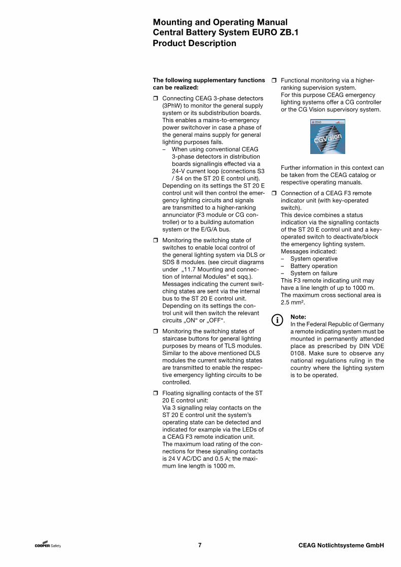
Functional monitoring via a higher-ranking supervision system. For this purpose CEAG emergency lighting systems offer a CG controller or the CG Vision supervisory system.
Further information in this context can be taken from the CEAG catalog or respective operating manuals.
Connection of a CEAG F3 remote indicator unit (with key-operated switch).
This device combines a status indication via the signalling contacts of the ST 20 E control unit and a key-operated switch to deactivate/block the emergency lighting system.
Messages indicated: – System operative
– Battery operation – System on failure This F3 remote indicating unit may
have a line length of up to 1000 m. The maximum cross sectional area is 2.5 mm².
Note:In the Federal Republic of Germany a remote indicating system must be mounted in permanently attended place as prescribed by DIN VDE 0108. Make sure to observe any national regulations ruling in the country where the lighting system is to be operated.
The following supplementary functions can be realized:
Connecting CEAG 3-phase detectors (3PhW) to monitor the general supply system or its subdistribution boards.
This enables a mains-to-emergency power switchover in case a phase of the general mains supply for general lighting purposes fails.– When using conventional CEAG
3-phase detectors in distribution boards signallingis effected via a 24-V current loop (connections S3 / S4 on the ST 20 E control unit).
Depending on its settings the ST 20 E control unit will then control the emer-gency lighting circuits and signals are transmitted to a higher-ranking annunciator (F3 module or CG con-troller) or to a building automation system or the E/G/A bus.
Monitoring the switching state of switches to enable local control of the general lighting system via DLS or SDS 8 modules. (see circuit diagrams under „11.7 Mounting and connec-tion of Internal Modules“ et sqq.). Messages indicating the current swit-ching states are sent via the internal bus to the ST 20 E control unit.
Depending on its settings the con-trol unit will then switch the relevant circuits „ON“ or „OFF“.
Monitoring the switching states of staircase buttons for general lighting purposes by means of TLS modules.
Similar to the above mentioned DLS modules the current switching states are transmitted to enable the respec-tive emergency lighting circuits to be controlled.
Floating signalling contacts of the ST 20 E control unit:
Via 3 signalling relay contacts on the ST 20 E control unit the system’s operating state can be detected and indicated for example via the LEDs of a CEAG F3 remote indication unit.
The maximum load rating of the con-nections for these signalling contacts is 24 V AC/DC and 0.5 A; the maxi-mum line length is 1000 m.
Product Description
Mounting and Operating ManualCentral Battery System EURO ZB.1
8 CEAG Notlichtsysteme GmbH
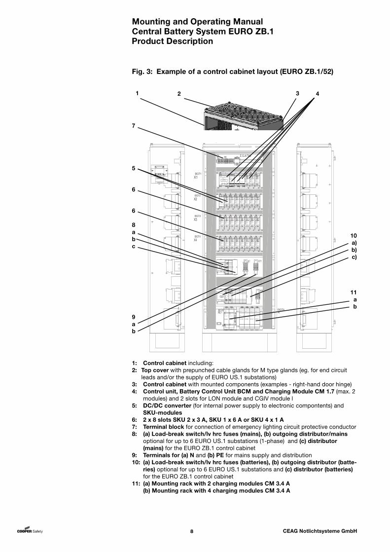
Fig. 3: Example of a control cabinet layout (EURO ZB.1/52)
1: Control cabinet including:2: Top cover with prepunched cable glands for M type glands (eg. for end circuit
leads and/or the supply of EURO US.1 substations)3: Control cabinet with mounted components (examples - right-hand door hinge)4: Control unit, Battery Control Unit BCM and Charging Module CM 1.7 (max. 2
modules) and 2 slots for LON module and CGIV module l5: DC/DC converter (for internal power supply to electronic compontents) and
SKU-modules6: 2 x 8 slots SKU 2 x 3 A, SKU 1 x 6 A or SKU 4 x 1 A 7: Terminal block for connection of emergency lighting circuit protective conductor8: (a) Load-break switch/lv hrc fuses (mains), (b) outgoing distributor/mains
optional for up to 6 EURO US.1 substations (1-phase) and (c) distributor (mains) for the EURO ZB.1 control cabinet
9: Terminals for (a) N and (b) PE for mains supply and distribution10: (a) Load-break switch/lv hrc fuses (batteries), (b) outgoing distributor (batte-
ries) optional for up to 6 EURO US.1 substations and (c) distributor (batteries) for the EURO ZB.1 control cabinet
11: (a) Mounting rack with 2 charging modules CM 3.4 A (b) Mounting rack with 4 charging modules CM 3.4 A
Product Description
BGT1X1
BGT2X2
BGT3X3
BGT4X4
E18 AC
E18-DC E18-DC
NBV
Q1L1 L2 L3
Q2
+ -
+ - Batterie
X71
X9
X7
L1 L3L2
BGT5
X8
X6
ST20 ZB96 kpl
22 32211211 31
Betrieb StorungNetzausfallBatterie-Operation FailureMains Failurebetrieb
BatteryOperation
CEAGSicherheitstechnik
ZB 96 Version 0.21
Menu
AGE
S4 GNDS2S1 S3 UH Drucker/Printer
SKU CG 2x3A
Service
Storung/FailureEin/On
NetzMains5AT
NetzMains5AT
Batt.
5AT+
Batt.
5AT+
Batt.
5AT-
Batt.
5AT-
U101 U202
SKU
1 2
1 2
Storung/FailureEin/On1
2
E
E
G G
G
A
A
A
E-G-A FilterE
BMK
X12
PE
VD
K
VD
K
SKU CG 2x3A
Service
Storung/FailureEin/On
NetzMains5AT
NetzMains5AT
Batt.
5AT+
Batt.
5AT+
Batt.
5AT-
Batt.
5AT-
U101 U202
SKU
1 2
1 2
Storung/FailureEin/On1
2
SKU CG 2x3A
Service
Storung/FailureEin/On
NetzMains5AT
NetzMains5AT
Batt.
5AT+
Batt.
5AT+
Batt.
5AT-
Batt.
5AT-
U101 U202
SKU
1 2
1 2
Storung/FailureEin/On1
2
SKU CG 2x3A
Service
Storung/FailureEin/On
NetzMains5AT
NetzMains5AT
Batt.
5AT+
Batt.
5AT+
Batt.
5AT-
Batt.
5AT-
U101 U202
SKU
1 2
1 2
Storung/FailureEin/On1
2
SKU CG 2x3A
Service
Storung/FailureEin/On
NetzMains5AT
NetzMains5AT
Batt.
5AT+
Batt.
5AT+
Batt.
5AT-
Batt.
5AT-
U101 U202
SKU
1 2
1 2
Storung/FailureEin/On1
2
SKU CG 2x3A
Service
Storung/FailureEin/On
NetzMains5AT
NetzMains5AT
Batt.
5AT+
Batt.
5AT+
Batt.
5AT-
Batt.
5AT-
U101 U202
SKU
1 2
1 2
Storung/FailureEin/On1
2
SKU CG 2x3A
Service
Storung/FailureEin/On
NetzMains5AT
NetzMains5AT
Batt.
5AT+
Batt.
5AT+
Batt.
5AT-
Batt.
5AT-
U101 U202
SKU
1 2
1 2
Storung/FailureEin/On1
2
SKU CG 2x3A
Service
Storung/FailureEin/On
NetzMains5AT
NetzMains5AT
Batt.
5AT+
Batt.
5AT+
Batt.
5AT-
Batt.
5AT-
U101 U202
SKU
1 2
1 2
Storung/FailureEin/On1
2
SKU CG 2x3A
Service
Storung/FailureEin/On
NetzMains5AT
NetzMains5AT
Batt.
5AT+
Batt.
5AT+
Batt.
5AT-
Batt.
5AT-
U101 U202
SKU
1 2
1 2
Storung/FailureEin/On1
2
SKU CG 2x3A
Service
Storung/FailureEin/On
NetzMains5AT
NetzMains5AT
Batt.
5AT+
Batt.
5AT+
Batt.
5AT-
Batt.
5AT-
U101 U202
SKU
1 2
1 2
Storung/FailureEin/On1
2
SKU CG 2x3A
Service
Storung/FailureEin/On
NetzMains5AT
NetzMains5AT
Batt.
5AT+
Batt.
5AT+
Batt.
5AT-
Batt.
5AT-
U101 U202
SKU
1 2
1 2
Storung/FailureEin/On1
2
SKU CG 2x3A
Service
Storung/FailureEin/On
NetzMains5AT
NetzMains5AT
Batt.
5AT+
Batt.
5AT+
Batt.
5AT-
Batt.
5AT-
U101 U202
SKU
1 2
1 2
Storung/FailureEin/On1
2
SKU CG 2x3A
Service
Storung/FailureEin/On
NetzMains5AT
NetzMains5AT
Batt.
5AT+
Batt.
5AT+
Batt.
5AT-
Batt.
5AT-
U101 U202
SKU
1 2
1 2
Storung/FailureEin/On1
2
SKU CG 2x3A
Service
Storung/FailureEin/On
NetzMains5AT
NetzMains5AT
Batt.
5AT+
Batt.
5AT+
Batt.
5AT-
Batt.
5AT-
U101 U202
SKU
1 2
1 2
Storung/FailureEin/On1
2
SKU CG 2x3A
Service
Storung/FailureEin/On
NetzMains5AT
NetzMains5AT
Batt.
5AT+
Batt.
5AT+
Batt.
5AT-
Batt.
5AT-
U101 U202
SKU
1 2
1 2
Storung/FailureEin/On1
2
SKU CG 2x3A
Service
Storung/FailureEin/On
NetzMains5AT
NetzMains5AT
Batt.
5AT+
Batt.
5AT+
Batt.
5AT-
Batt.
5AT-
U101 U202
SKU
1 2
1 2
Storung/FailureEin/On1
2
SKU CG 2x3A
Service
Storung/FailureEin/On
NetzMains5AT
NetzMains5AT
Batt.
5AT+
Batt.
5AT+
Batt.
5AT-
Batt.
5AT-
U101 U202
SKU
1 2
1 2
Storung/FailureEin/On1
2
SKU CG 2x3A
Service
Storung/FailureEin/On
NetzMains5AT
NetzMains5AT
Batt.
5AT+
Batt.
5AT+
Batt.
5AT-
Batt.
5AT-
U101 U202
SKU
1 2
1 2
Storung/FailureEin/On1
2
SKU CG 2x3A
Service
Storung/FailureEin/On
NetzMains5AT
NetzMains5AT
Batt.
5AT+
Batt.
5AT+
Batt.
5AT-
Batt.
5AT-
U101 U202
SKU
1 2
1 2
Storung/FailureEin/On1
2
SKU CG 2x3A
Service
Storung/FailureEin/On
NetzMains5AT
NetzMains5AT
Batt.
5AT+
Batt.
5AT+
Batt.
5AT-
Batt.
5AT-
U101 U202
SKU
1 2
1 2
Storung/FailureEin/On1
2
SKU CG 2x3A
Service
Storung/FailureEin/On
NetzMains5AT
NetzMains5AT
Batt.
5AT+
Batt.
5AT+
Batt.
5AT-
Batt.
5AT-
U101 U202
SKU
1 2
1 2
Storung/FailureEin/On1
2
SKU CG 2x3A
Service
Storung/FailureEin/On
NetzMains5AT
NetzMains5AT
Batt.
5AT+
Batt.
5AT+
Batt.
5AT-
Batt.
5AT-
U101 U202
SKU
1 2
1 2
Storung/FailureEin/On1
2
SKU CG 2x3A
Service
Storung/FailureEin/On
NetzMains5AT
NetzMains5AT
Batt.
5AT+
Batt.
5AT+
Batt.
5AT-
Batt.
5AT-
U101 U202
SKU
1 2
1 2
Storung/FailureEin/On1
2
SO
BGT6X6.1
AD
AD AD AD AD
EM
V-D
R
TR
ESCH
Frontansicht geöffnetInnere Seitenansicht links Innere Seitenansicht rechts
A-1 DC-DC
+-+-21IN 24VDC
OUT
24V extern
24V intern
6V intern
DC-DC Wandler.2
SKU CG 2x3A
Service
Storung/FailureEin/On
NetzMains5AT
NetzMains5AT
Batt.
5AT+
Batt.
5AT+
Batt.
5AT-
Batt.
5AT-
U101 U202
SKU
1 2
1 2
Storung/FailureEin/On1
2
SKU CG 2x3A
Service
Storung/FailureEin/On
NetzMains5AT
NetzMains5AT
Batt.
5AT+
Batt.
5AT+
Batt.
5AT-
Batt.
5AT-
U101 U202
SKU
1 2
1 2
Storung/FailureEin/On1
2
SKU CG 2x3A
Service
Storung/FailureEin/On
NetzMains5AT
NetzMains5AT
Batt.
5AT+
Batt.
5AT+
Batt.
5AT-
Batt.
5AT-
U101 U202
SKU
1 2
1 2
Storung/FailureEin/On1
2
+ -24V In
+ -CCB
+ -I
+ -F
11 12 21 31 32 + -22BST
Ein/OnStarkladung / Boost-ChargeLadestorung / Charge-Failure
ServiceISO-Fehler / ISO-Failure
ISO-Test -
ISO-Test +
BCMBattery Control Module
+ -+ -
CM 1.7A DCCharger Module
Ein/On
CCB
S2S1
+ -+ -
CM 1.7A DCCharger Module
Ein/On
CCB
S2S1
Booster EinOn Booster Ein
On Booster EinOn Booster Ein
On Booster EinOn Booster Ein
On
7
5
6
6
8abc
9ab
10a)b)c)
11ab
1 2 3 4
Mounting and Operating ManualCentral Battery System EURO ZB.1
9 CEAG Notlichtsysteme GmbH
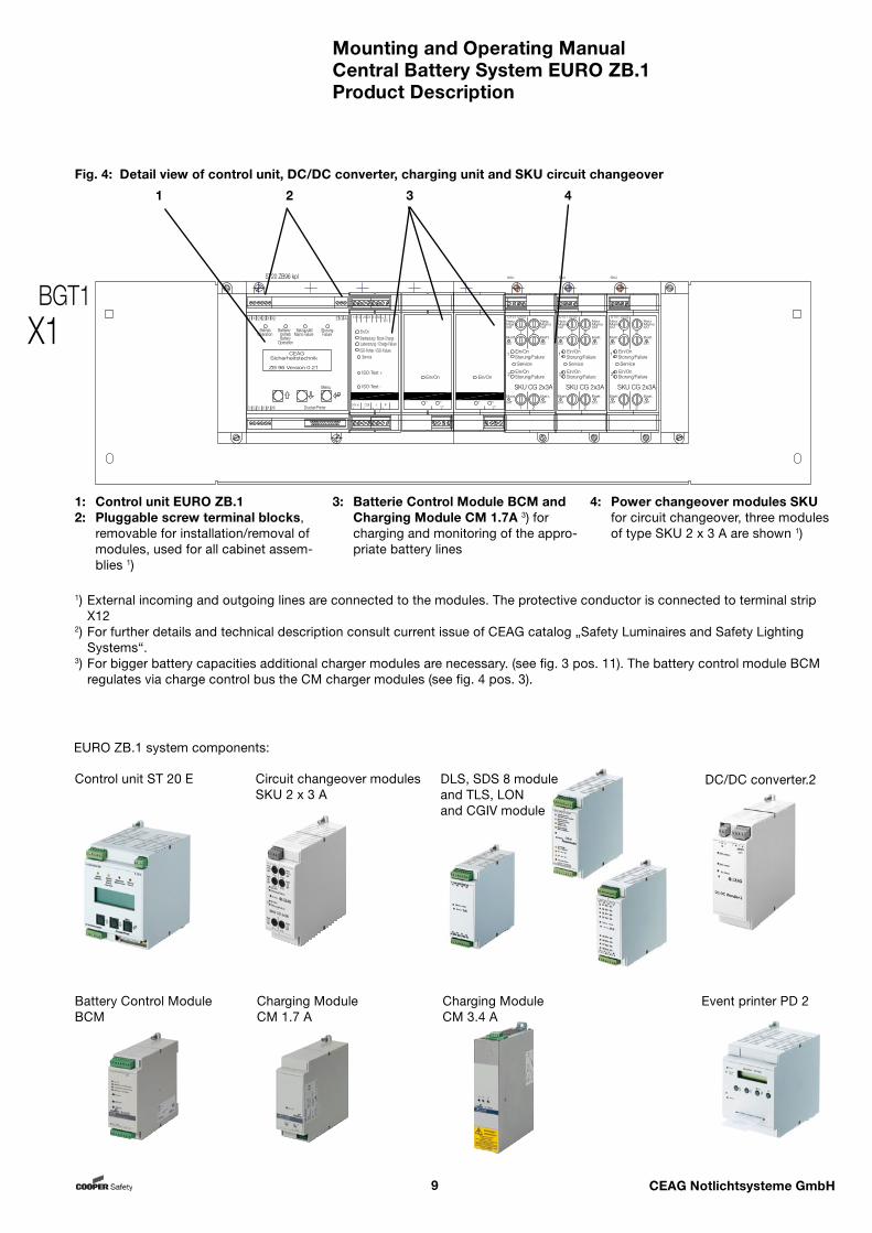
1: Control unit EURO ZB.12: Pluggable screw terminal blocks,
removable for installation/removal of modules, used for all cabinet assem-blies 1)
4: Power changeover modules SKU for circuit changeover, three modules of type SKU 2 x 3 A are shown 1)
1) External incoming and outgoing lines are connected to the modules. The protective conductor is connected to terminal strip X12
2) For further details and technical description consult current issue of CEAG catalog „Safety Luminaires and Safety Lighting Systems“.
3) For bigger battery capacities additional charger modules are necessary. (see fig. 3 pos. 11). The battery control module BCM regulates via charge control bus the CM charger modules (see fig. 4 pos. 3).
Fig. 4: Detail view of control unit, DC/DC converter, charging unit and SKU circuit changeover
Product Description
EURO ZB.1 system components:
Circuit changeover modulesSKU 2 x 3 A
Control unit ST 20 E
ST20 ZB96 kpl
22 32211211 31
Betrieb StorungNetzausfallBatterie-Operation FailureMains Failurebetrieb
BatteryOperation
CEAGSicherheitstechnik
ZB 96 Version 0.21
Menu
AGE
S4 GNDS2S1 S3 UH Drucker/Printer
SKU CG 2x3A
Service
Storung/FailureEin/On
NetzMains5AT
NetzMains5AT
Batt.
5AT+
Batt.
5AT+
Batt.
5AT-
Batt.
5AT-
U101 U202
SKU
1 2
1 2
Storung/FailureEin/On1
2
SKU CG 2x3A
Service
Storung/FailureEin/On
NetzMains5AT
NetzMains5AT
Batt.
5AT+
Batt.
5AT+
Batt.
5AT-
Batt.
5AT-
U101 U202
SKU
1 2
1 2
Storung/FailureEin/On1
2
SKU CG 2x3A
Service
Storung/FailureEin/On
NetzMains5AT
NetzMains5AT
Batt.
5AT+
Batt.
5AT+
Batt.
5AT-
Batt.
5AT-
U101 U202
SKU
1 2
1 2
Storung/FailureEin/On1
2
+ -24V In
+ -CCB
+ -I
+ -F
11 12 21 31 32 + -22BST
Ein/OnStarkladung / Boost-ChargeLadestorung / Charge-Failure
ServiceISO-Fehler / ISO-Failure
ISO-Test -
ISO-Test +
BCMBattery Control Module
+ -+ -
CM 1.7A DCCharger Module
Ein/On
CCB
S2S1
+ -+ -
CM 1.7A DCCharger Module
Ein/On
CCB
S2S1
BGT1X1
1 2 3 4
3: Batterie Control Module BCM and Charging Module CM 1.7A 3) for charging and monitoring of the appro-priate battery lines
DC/DC converter.2
Charging ModuleCM 1.7 A
Charging ModuleCM 3.4 A
Event printer PD 2Battery Control Module BCM
DLS, SDS 8 moduleand TLS, LONand CGIV module
Mounting and Operating ManualCentral Battery System EURO ZB.1
10 CEAG Notlichtsysteme GmbH
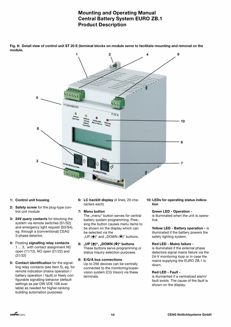
Fig. 8: Detail view of control unit ST 20 E (terminal blocks on module serve to facilitate mounting and removal ov the module.
1: Control unit housing
2: Safety screw for the plug-type con-trol unit module
3: 24V query contacts for blocking the system via remote switches (S1/S2) and emergency light request (S3/S4), eg. through a (conventional) CEAG 3-phase detector.
4: Floating signalling relay contacts 1 ... 3, with contact assignment NC open (11/12), NO open (21/22) and (31/32)
5: Contact identification for the signal-ling relay contacts (see Item 5), eg. for remote indication (mains operation / battery operation / fault) or freely con-figurable signalling behavior (default settings as per DIN VDE 108 avai-lable) as needed for higher-ranking building automation purposes.
6: LC backlit display (4 lines, 20 cha-racters each)
7: Menu button The „menu“ button serves for central battery system programming. Pres-sing the button causes menu items to be shown on the display which can be selected via the „UP ()“ and „DOWN ()“ buttons.
8: „UP ()“, „DOWN ()“ buttons These buttons serve programming or
status inquiry selection purposes.
9: E/G/A bus connections Up to 256 devices can be centrally
connected to the monitoring/super-vision system (CG Vision) via these terminals.
10: LEDs for operating status indica-tion
Green LED - Operation - is illuminated when the unit is opera-tive.
Yellow LED - Battery operation - is illuminated if the battery powers the safety lighting system.
Red LED - Mains failure - is illuminated if the external phase detectors signal mains failure via the 24-V monitoring loop or in case the mains supplying the EURO ZB.1 is down.
Red LED - Fault - is illumianted if a centralized alarm/fault exists. The cause of the fault is shown on the display.
Product Description
10
6
7
5
8
3
1 2 4 9

Mounting and Operating ManualCentral Battery System EURO ZB.1
11 CEAG Notlichtsysteme GmbH
EURO ZB.1 Control Cabinet EURO ZB.1/52Rated operating voltage: 400/230 V 50 HzControl unit EURO ZB.1 1 DC/DC converter.2 1 Batterie Control Module BCM 1 Circuit module SKU 0 - 26 6)Charging Module CM 1.7 A 0 - 2 1)Charging Module CM 3.4 A 0 - 6 1)Outgoing distributor, 1-phase outgoing circuits (optional) 0 - 6 2) Dimensions (mm) W 800 H 2050 D 400plus optional base (mm) H 100/200Weight (depends on components mounted) upon requestAdm. system temperature ranges: storage -20 °C to + 40 °C operation -5 °C to + 35 °C Batteries: Nominal temperature + 20 °C 4) Enclosure type as per DIN EN 60 529 IP21Prot. class as per DIN EN 60 598 I 3-phase system division Wiring blockCable entry at top/bottom possible yes / yes Conductor size 3) Battery and mains lead up to 50 mm2
Outgoing distributor up to 16 mm2
Final circuits up to 2,5 mm2
Control unit EURO ZB.1 up to 2.5 mm2 conductor size
Battery power supply via CEAG standardbattery cabinet 1-fold 23.3 - 89.4 Ah 5) (W x D x H, in mm) 800 x 400 x 2050 2-fold 118 - 178.8 Ah 5) 4)
1) when mounting 6 charging modules an additional booster carrier, 2-fold, must be arranged2) for 1-phase operation (for 3-phase operation 0-2 outgoing circuits)3) Conductor sizes of the connecting leads must be selected to suit the type of mains power
supply and requirements of the consumer circuits in line with the applicable regulations and standards (ruling at the operating location of the plant)
4) The optimum operating temperature is +20 °C. Lower temperatures will impair the available capacity. Higher temperatures will reduce the usability period. The technical data apply to a nominal temperature of +20 °C.
5) The battery capacity may be raised to 240 Ah by a connection in parallel.6) Plus max. two additional slots in correlation of CM 1.7 A and CM 3.4 A placement.
Technical Data
Fig. 9: Inside view of EURO ZB.1/523 Technical Data
Fig.10: Cable entries are prepunched (here EURO ZB.1/52, other types, eg. sponge rubber, are available on request)
1 = M40/M322 = M323 = M164 = M20/M25
1 3
2 3
4
4
BGT1X1
BGT2X2
BGT3X3
BGT4X4
E18 AC
E18-DC E18-DC
NBV
Q1L1 L2 L3
Q2
+ -
+ - Batterie
X71
X9
X7
L1 L3L2
BGT5
X8
X6
ST20 ZB96 kpl
22 32211211 31
Betrieb StorungNetzausfallBatterie-Operation FailureMains Failurebetrieb
BatteryOperation
CEAGSicherheitstechnik
ZB 96 Version 0.21
Menu
AGE
S4 GNDS2S1 S3 UH Drucker/Printer
SKU CG 2x3A
Service
Storung/FailureEin/On
NetzMains5AT
NetzMains5AT
Batt.
5AT+
Batt.
5AT+
Batt.
5AT-
Batt.
5AT-
U101 U202
SKU
1 2
1 2
Storung/FailureEin/On1
2
E
E
G G
G
A
A
A
E-G-A FilterE
BMK
X12
PE
VD
K
VD
K
SKU CG 2x3A
Service
Storung/FailureEin/On
NetzMains5AT
NetzMains5AT
Batt.
5AT+
Batt.
5AT+
Batt.
5AT-
Batt.
5AT-
U101 U202
SKU
1 2
1 2
Storung/FailureEin/On1
2
SKU CG 2x3A
Service
Storung/FailureEin/On
NetzMains5AT
NetzMains5AT
Batt.
5AT+
Batt.
5AT+
Batt.
5AT-
Batt.
5AT-
U101 U202
SKU
1 2
1 2
Storung/FailureEin/On1
2
SKU CG 2x3A
Service
Storung/FailureEin/On
NetzMains5AT
NetzMains5AT
Batt.
5AT+
Batt.
5AT+
Batt.
5AT-
Batt.
5AT-
U101 U202
SKU
1 2
1 2
Storung/FailureEin/On1
2
SKU CG 2x3A
Service
Storung/FailureEin/On
NetzMains5AT
NetzMains5AT
Batt.
5AT+
Batt.
5AT+
Batt.
5AT-
Batt.
5AT-
U101 U202
SKU
1 2
1 2
Storung/FailureEin/On1
2
SKU CG 2x3A
Service
Storung/FailureEin/On
NetzMains5AT
NetzMains5AT
Batt.
5AT+
Batt.
5AT+
Batt.
5AT-
Batt.
5AT-
U101 U202
SKU
1 2
1 2
Storung/FailureEin/On1
2
SKU CG 2x3A
Service
Storung/FailureEin/On
NetzMains5AT
NetzMains5AT
Batt.
5AT+
Batt.
5AT+
Batt.
5AT-
Batt.
5AT-
U101 U202
SKU
1 2
1 2
Storung/FailureEin/On1
2
SKU CG 2x3A
Service
Storung/FailureEin/On
NetzMains5AT
NetzMains5AT
Batt.
5AT+
Batt.
5AT+
Batt.
5AT-
Batt.
5AT-
U101 U202
SKU
1 2
1 2
Storung/FailureEin/On1
2
SKU CG 2x3A
Service
Storung/FailureEin/On
NetzMains5AT
NetzMains5AT
Batt.
5AT+
Batt.
5AT+
Batt.
5AT-
Batt.
5AT-
U101 U202
SKU
1 2
1 2
Storung/FailureEin/On1
2
SKU CG 2x3A
Service
Storung/FailureEin/On
NetzMains5AT
NetzMains5AT
Batt.
5AT+
Batt.
5AT+
Batt.
5AT-
Batt.
5AT-
U101 U202
SKU
1 2
1 2
Storung/FailureEin/On1
2
SKU CG 2x3A
Service
Storung/FailureEin/On
NetzMains5AT
NetzMains5AT
Batt.
5AT+
Batt.
5AT+
Batt.
5AT-
Batt.
5AT-
U101 U202
SKU
1 2
1 2
Storung/FailureEin/On1
2
SKU CG 2x3A
Service
Storung/FailureEin/On
NetzMains5AT
NetzMains5AT
Batt.
5AT+
Batt.
5AT+
Batt.
5AT-
Batt.
5AT-
U101 U202
SKU
1 2
1 2
Storung/FailureEin/On1
2
SKU CG 2x3A
Service
Storung/FailureEin/On
NetzMains5AT
NetzMains5AT
Batt.
5AT+
Batt.
5AT+
Batt.
5AT-
Batt.
5AT-
U101 U202
SKU
1 2
1 2
Storung/FailureEin/On1
2
SKU CG 2x3A
Service
Storung/FailureEin/On
NetzMains5AT
NetzMains5AT
Batt.
5AT+
Batt.
5AT+
Batt.
5AT-
Batt.
5AT-
U101 U202
SKU
1 2
1 2
Storung/FailureEin/On1
2
SKU CG 2x3A
Service
Storung/FailureEin/On
NetzMains5AT
NetzMains5AT
Batt.
5AT+
Batt.
5AT+
Batt.
5AT-
Batt.
5AT-
U101 U202
SKU
1 2
1 2
Storung/FailureEin/On1
2
SKU CG 2x3A
Service
Storung/FailureEin/On
NetzMains5AT
NetzMains5AT
Batt.
5AT+
Batt.
5AT+
Batt.
5AT-
Batt.
5AT-
U101 U202
SKU
1 2
1 2
Storung/FailureEin/On1
2
SKU CG 2x3A
Service
Storung/FailureEin/On
NetzMains5AT
NetzMains5AT
Batt.
5AT+
Batt.
5AT+
Batt.
5AT-
Batt.
5AT-
U101 U202
SKU
1 2
1 2
Storung/FailureEin/On1
2
SKU CG 2x3A
Service
Storung/FailureEin/On
NetzMains5AT
NetzMains5AT
Batt.
5AT+
Batt.
5AT+
Batt.
5AT-
Batt.
5AT-
U101 U202
SKU
1 2
1 2
Storung/FailureEin/On1
2
SKU CG 2x3A
Service
Storung/FailureEin/On
NetzMains5AT
NetzMains5AT
Batt.
5AT+
Batt.
5AT+
Batt.
5AT-
Batt.
5AT-
U101 U202
SKU
1 2
1 2
Storung/FailureEin/On1
2
SKU CG 2x3A
Service
Storung/FailureEin/On
NetzMains5AT
NetzMains5AT
Batt.
5AT+
Batt.
5AT+
Batt.
5AT-
Batt.
5AT-
U101 U202
SKU
1 2
1 2
Storung/FailureEin/On1
2
SKU CG 2x3A
Service
Storung/FailureEin/On
NetzMains5AT
NetzMains5AT
Batt.
5AT+
Batt.
5AT+
Batt.
5AT-
Batt.
5AT-
U101 U202
SKU
1 2
1 2
Storung/FailureEin/On1
2
SKU CG 2x3A
Service
Storung/FailureEin/On
NetzMains5AT
NetzMains5AT
Batt.
5AT+
Batt.
5AT+
Batt.
5AT-
Batt.
5AT-
U101 U202
SKU
1 2
1 2
Storung/FailureEin/On1
2
SKU CG 2x3A
Service
Storung/FailureEin/On
NetzMains5AT
NetzMains5AT
Batt.
5AT+
Batt.
5AT+
Batt.
5AT-
Batt.
5AT-
U101 U202
SKU
1 2
1 2
Storung/FailureEin/On1
2
SO
BGT6X6.1
AD
AD AD AD AD
EM
V-D
R
TR
ESCH
Frontansicht geöffnetInnere Seitenansicht links Innere Seitenansicht rechts
A-1 DC-DC
+-+-21IN 24VDC
OUT
24V extern
24V intern
6V intern
DC-DC Wandler.2
SKU CG 2x3A
Service
Storung/FailureEin/On
NetzMains5AT
NetzMains5AT
Batt.
5AT+
Batt.
5AT+
Batt.
5AT-
Batt.
5AT-
U101 U202
SKU
1 2
1 2
Storung/FailureEin/On1
2
SKU CG 2x3A
Service
Storung/FailureEin/On
NetzMains5AT
NetzMains5AT
Batt.
5AT+
Batt.
5AT+
Batt.
5AT-
Batt.
5AT-
U101 U202
SKU
1 2
1 2
Storung/FailureEin/On1
2
SKU CG 2x3A
Service
Storung/FailureEin/On
NetzMains5AT
NetzMains5AT
Batt.
5AT+
Batt.
5AT+
Batt.
5AT-
Batt.
5AT-
U101 U202
SKU
1 2
1 2
Storung/FailureEin/On1
2
+ -24V In
+ -CCB
+ -I
+ -F
11 12 21 31 32 + -22BST
Ein/OnStarkladung / Boost-ChargeLadestorung / Charge-Failure
ServiceISO-Fehler / ISO-Failure
ISO-Test -
ISO-Test +
BCMBattery Control Module
+ -+ -
CM 1.7A DCCharger Module
Ein/On
CCB
S2S1
+ -+ -
CM 1.7A DCCharger Module
Ein/On
CCB
S2S1
Booster EinOn Booster Ein
On Booster EinOn Booster Ein
On Booster EinOn Booster Ein
On

Mounting and Operating ManualCentral Battery System EURO ZB.1
12 CEAG Notlichtsysteme GmbH
Compact Control Cabinet EURO ZB.1/20K /26K /188K /18KRated operating voltage: --------------- 230 V 50 Hz ----------------Control unit EURO ZB.1 1 1 1 1DC/DC converter.2 1 1 1 1Battery Control Module BCM 1 1 1 1Circuit module SKU 0 - 10 3) 0 - 10 3) 0 - 18 3) 0 - 10 3)Charging Module 1.7 A 0 - 2 0 - 2 1 1Charging Module 3.4 A 0 - 1 1) 0 - 2 2) 0 0Outgoing distributor, 1-phase, Outgoing circuits 2 2 1) 1 1Dimensions (mm) W 800 800 600 600 H 2050 2050 1800 1800 D 400 600 350 350plus optional base (mm) H 200 – 200 200Weight (depends on outfit) upon requestAdm. system temperature ranges: storage -20 °C to + 40 °C dtto. operation -5 °C to + 35 °C dtto. Batteries: Nominal temperature + 20 °C 5) Enclosure type (DIN EN 60 529) IP21 IP21 IP21 IP21Prot. class as per DIN EN 60 598 I I I I3-phase system division no no no noCable entryat top/bottom possible yes / no yes / no yes / no yes/noConductor size 4) Battery and mains leads up to 16 mm2 16 mm2 16 mm2 16 mm2
Outgoing distributor up to 35 mm2 35 mm2 16 mm2 16 mm2
Final circuits up to 2.5 mm2
Control unit ST20 up to 2.5 mm2 conductor sizeBattery power supply via CEAG compact battery cabinet (Ah) 5.5 - 49.5 5.5 - 89.4 5.5 - 23.3 5.5-23.3(W x D x H in mm) see applicable mounting and operating manual
1) When mounting up to 1 Charging Module a 1-fold charging booster adapter must be provided.2) When mounting up to 2 Charging Modules a 2-fold charging booster adapter
must be provided.6) Plus max. two additional slots in correlation of CM 1.7 A and CM 3.4 A place-
ment.
Technical Data
Fig. 9a: Inside view of EURO ZB.1/188K
Attention! When planning the equipment and during subsequent operation make sure that
the systems are sufficiently cooled (compare remarks under „Adm. temperature ranges“),
environmental requirements are met as per type of enclosure and pro-tection class (regarding protection against contact with live components and ingress of dust, foreign materials or moisture),
the line length of an emergency lighting circuit up to the last luminaire of the circuit does not exceed the admissible line length.
Frontansicht geöffnet (ohne Batterie)Innere Seitenansicht links Innere Seitenansicht rechts
L N L? + -
-+N L?L
F10 F30F50
F50
PE PE PEN?
X8 X7 X9
LN
+-
F10F30PEPEPE N?
LN
+-
BGT1
BGT2
+ - Battery
MP
E E G G A A
E G A
Q2
LN
+-
BGT3
E-G-A Filter
X1
X2
X3
X12
PE
F F
CS
TR
DR
SO
ST
22 32211211 31
Betrieb StorungNetzausfallBatterie-Operation FailureMains Failurebetrieb
BatteryOperation
CEAGSicherheitstechnik
ZB 96 Version 0.21
Menu
AGE
S4 GNDS2S1 S3 UH Drucker/Printer
DC-DC
+-+-21IN 24VDC
OUT
24V extern
24V intern
6V intern
DC-DC Wandler.2 SKU 2x3A
Service
Storung/FailureEin/On
NetzMains5AT
NetzMains5AT
Batt.
5AT+
Batt.
5AT+
Batt.
5AT-
Batt.
5AT-
U101 U202
SKU
1 2
1 2
Storung/FailureEin/On1
2
SKU 2x3A
Service
Storung/FailureEin/On
NetzMains5AT
NetzMains5AT
Batt.
5AT+
Batt.
5AT+
Batt.
5AT-
Batt.
5AT-
U101 U202
SKU
1 2
1 2
Storung/FailureEin/On1
2
SKU 2x3A
Service
Storung/FailureEin/On
NetzMains5AT
NetzMains5AT
Batt.
5AT+
Batt.
5AT+
Batt.
5AT-
Batt.
5AT-
U101 U202
SKU
1 2
1 2
Storung/FailureEin/On1
2
SKU 2x3A
Service
Storung/FailureEin/On
NetzMains5AT
NetzMains5AT
Batt.
5AT+
Batt.
5AT+
Batt.
5AT-
Batt.
5AT-
U101 U202
SKU
1 2
1 2
Storung/FailureEin/On1
2
SKU 2x3A
Service
Storung/FailureEin/On
NetzMains5AT
NetzMains5AT
Batt.
5AT+
Batt.
5AT+
Batt.
5AT-
Batt.
5AT-
U101 U202
SKU
1 2
1 2
Storung/FailureEin/On1
2
SKU 2x3A
Service
Storung/FailureEin/On
NetzMains5AT
NetzMains5AT
Batt.
5AT+
Batt.
5AT+
Batt.
5AT-
Batt.
5AT-
U101 U202
SKU
1 2
1 2
Storung/FailureEin/On1
2
SKU 2x3A
Service
Storung/FailureEin/On
NetzMains5AT
NetzMains5AT
Batt.
5AT+
Batt.
5AT+
Batt.
5AT-
Batt.
5AT-
U101 U202
SKU
1 2
1 2
Storung/FailureEin/On1
2
SKU 2x3A
Service
Storung/FailureEin/On
NetzMains5AT
NetzMains5AT
Batt.
5AT+
Batt.
5AT+
Batt.
5AT-
Batt.
5AT-
U101 U202
SKU
1 2
1 2
Storung/FailureEin/On1
2
SKU 2x3A
Service
Storung/FailureEin/On
NetzMains5AT
NetzMains5AT
Batt.
5AT+
Batt.
5AT+
Batt.
5AT-
Batt.
5AT-
U101 U202
SKU
1 2
1 2
Storung/FailureEin/On1
2
SKU 2x3A
Service
Storung/FailureEin/On
NetzMains5AT
NetzMains5AT
Batt.
5AT+
Batt.
5AT+
Batt.
5AT-
Batt.
5AT-
U101 U202
SKU
1 2
1 2
Storung/FailureEin/On1
2
SKU 2x3A
Service
Storung/FailureEin/On
NetzMains5AT
NetzMains5AT
Batt.
5AT+
Batt.
5AT+
Batt.
5AT-
Batt.
5AT-
U101 U202
SKU
1 2
1 2
Storung/FailureEin/On1
2
SKU 2x3A
Service
Storung/FailureEin/On
NetzMains5AT
NetzMains5AT
Batt.
5AT+
Batt.
5AT+
Batt.
5AT-
Batt.
5AT-
U101 U202
SKU
1 2
1 2
Storung/FailureEin/On1
2
SKU 2x3A
Service
Storung/FailureEin/On
NetzMains5AT
NetzMains5AT
Batt.
5AT+
Batt.
5AT+
Batt.
5AT-
Batt.
5AT-
U101 U202
SKU
1 2
1 2
Storung/FailureEin/On1
2
SKU 2x3A
Service
Storung/FailureEin/On
NetzMains5AT
NetzMains5AT
Batt.
5AT+
Batt.
5AT+
Batt.
5AT-
Batt.
5AT-
U101 U202
SKU
1 2
1 2
Storung/FailureEin/On1
2
SKU 2x3A
Service
Storung/FailureEin/On
NetzMains5AT
NetzMains5AT
Batt.
5AT+
Batt.
5AT+
Batt.
5AT-
Batt.
5AT-
U101 U202
SKU
1 2
1 2
Storung/FailureEin/On1
2
SKU 2x3A
Service
Storung/FailureEin/On
NetzMains5AT
NetzMains5AT
Batt.
5AT+
Batt.
5AT+
Batt.
5AT-
Batt.
5AT-
U101 U202
SKU
1 2
1 2
Storung/FailureEin/On1
2
SKU 2x3A
Service
Storung/FailureEin/On
NetzMains5AT
NetzMains5AT
Batt.
5AT+
Batt.
5AT+
Batt.
5AT-
Batt.
5AT-
U101 U202
SKU
1 2
1 2
Storung/FailureEin/On1
2
SKU 2x3A
Service
Storung/FailureEin/On
NetzMains5AT
NetzMains5AT
Batt.
5AT+
Batt.
5AT+
Batt.
5AT-
Batt.
5AT-
U101 U202
SKU
1 2
1 2
Storung/FailureEin/On1
2
+ -24V In
+ -CCB
+ -I
+ -F
11 12 21 31 32 + -22BST
Ein/OnStarkladung / Boost-ChargeLadestorung / Charge-Failure
ServiceISO-Fehler / ISO-Failure
ISO-Test -
ISO-Test +
BCMBattery Control Module
+ -+ -
CM 1.7A DCCharger Module
Ein/On
CCB
S2S1
+ -+ -
CM 1.7A DCCharger Module
Ein/On
CCB
S2S1

Mounting and Operating ManualCentral Battery System EURO ZB.1
13 CEAG Notlichtsysteme GmbH
Fig. 9a: Inside view of EURO ZB.1/204K
Compact Control Cabinet EURO ZB.1/204K /264KRated operating voltage: --------------- 230 V 50/60 Hz---------------Control unit EURO ZB.1 1 1 DC/DC converter.2 1 1 Battery Control Module BCM 1 1 Circuit module SKU 0 - 14 0 - 14 Charging Module 1.7 A 0 - 2 0 - 2 Charging Module 3.4 A 0 - 1 1) 0 - 2 2) Outgoing distributor, 1-phase, Outgoing circuits - - Dimensions (mm) W 800 800 H 2050 2050 D 400 600 plus optional base (mm) H 200 – Weight (depends on components mounted) upon requestAdm. system temperature range: storage -20 °C to + 40 °C operation -5 °C to + 35 °C Batteries: Nominal temperature + 20 °C 5) Enclosure type as per DIN EN 60 529 IP21 IP21 Prot. class as per DIN EN 60 598 I I 3-phase system division no no Cable entryat top/bottom possible yes / no yes / no Conductor size 4) Battery and mains leads up to 16 mm2 16 mm2
Outgoing distributor up to - -
Final circuits up to 2.5 mm2 2.5 mm2 Control unit ST 20 E up to 2.5 mm2 conductor size Battery power supply via CEAG compact battery cabinet (Ah) 5.5 - 49.5 5.5 - 89.4(W x D x H in mm) see pertinent mounting and operating manual
1) When mounting up to 1 Charging Module a 1-fold charging booster adapter must be provided.2) When mounting up to 2 Charging Modules a 2-fold charging booster adapter
must be provided.3) Plus max. two additional slots in correlation of CM 1.7 A and CM 3.4 A place-
ment.
Technical Data
Fig.10: Cable entries are prepunched (here EURO ZB.1/52, other types, eg. sponge rubber, are available on request)
1 = M40/M322 = M323 = M164 = M20/M25
1 3
2 3
4
4
BGT3X3
TF
X9
BK
BK
AW
AW
AW
AW
NPEX8
E
E
G G
G
A
A
A
L
Q2+ - Batterie
E-G-A Filter
E
TK
X1BGT1
PE
BGT2X2
VK
VS M20x1,5
SKM M20x1,5
VS M20x1,5
SKMM20x1,5
BGT4X6
VK
-1
SO
F F
DC
+-+-21IN 24VDC
OUT
24V extern
24V intern
6V intern
DC-DC Wandler.2
AC
EM
V-D
R
SKU 2x3A
Service
Storung/FailureEin/On
NetzMains5AT
NetzMains5AT
Batt.
5AT+
Batt.
5AT+
Batt.
5AT-
Batt.
5AT-
U101 U202
SKU
1 2
1 2
Storung/FailureEin/On1
2
SKU 2x3A
Service
Storung/FailureEin/On
NetzMains5AT
NetzMains5AT
Batt.
5AT+
Batt.
5AT+
Batt.
5AT-
Batt.
5AT-
U101 U202
SKU
1 2
1 2
Storung/FailureEin/On1
2
SKU 2x3A
Service
Storung/FailureEin/On
NetzMains5AT
NetzMains5AT
Batt.
5AT+
Batt.
5AT+
Batt.
5AT-
Batt.
5AT-
U101 U202
SKU
1 2
1 2
Storung/FailureEin/On1
2
SKU 2x3A
Service
Storung/FailureEin/On
NetzMains5AT
NetzMains5AT
Batt.
5AT+
Batt.
5AT+
Batt.
5AT-
Batt.
5AT-
U101 U202
SKU
1 2
1 2
Storung/FailureEin/On1
2
SKU 2x3A
Service
Storung/FailureEin/On
NetzMains5AT
NetzMains5AT
Batt.
5AT+
Batt.
5AT+
Batt.
5AT-
Batt.
5AT-
U101 U202
SKU
1 2
1 2
Storung/FailureEin/On1
2
SKU 2x3A
Service
Storung/FailureEin/On
NetzMains5AT
NetzMains5AT
Batt.
5AT+
Batt.
5AT+
Batt.
5AT-
Batt.
5AT-
U101 U202
SKU
1 2
1 2
Storung/FailureEin/On1
2
SKU 2x3A
Service
Storung/FailureEin/On
NetzMains5AT
NetzMains5AT
Batt.
5AT+
Batt.
5AT+
Batt.
5AT-
Batt.
5AT-
U101 U202
SKU
1 2
1 2
Storung/FailureEin/On1
2
SKU 2x3A
Service
Storung/FailureEin/On
NetzMains5AT
NetzMains5AT
Batt.
5AT+
Batt.
5AT+
Batt.
5AT-
Batt.
5AT-
U101 U202
SKU
1 2
1 2
Storung/FailureEin/On1
2
SKU 2x3A
Service
Storung/FailureEin/On
NetzMains5AT
NetzMains5AT
Batt.
5AT+
Batt.
5AT+
Batt.
5AT-
Batt.
5AT-
U101 U202
SKU
1 2
1 2
Storung/FailureEin/On1
2
SKU 2x3A
Service
Storung/FailureEin/On
NetzMains5AT
NetzMains5AT
Batt.
5AT+
Batt.
5AT+
Batt.
5AT-
Batt.
5AT-
U101 U202
SKU
1 2
1 2
Storung/FailureEin/On1
2
SKU 2x3A
Service
Storung/FailureEin/On
NetzMains5AT
NetzMains5AT
Batt.
5AT+
Batt.
5AT+
Batt.
5AT-
Batt.
5AT-
U101 U202
SKU
1 2
1 2
Storung/FailureEin/On1
2
ST
22 32211211 31
Betrieb StorungNetzausfallBatterie-Operation FailureMains Failurebetrieb
BatteryOperation
CEAGSicherheitstechnik
ZB 96 Version 0.21
Menu
AGE
S4 GNDS2S1 S3 UH Drucker/Printer
SKU 2x3A
Service
Storung/FailureEin/On
NetzMains5AT
NetzMains5AT
Batt.
5AT+
Batt.
5AT+
Batt.
5AT-
Batt.
5AT-
U101 U202
SKU
1 2
1 2
Storung/FailureEin/On1
2
SKU 2x3A
Service
Storung/FailureEin/On
NetzMains5AT
NetzMains5AT
Batt.
5AT+
Batt.
5AT+
Batt.
5AT-
Batt.
5AT-
U101 U202
SKU
1 2
1 2
Storung/FailureEin/On1
2
SKU 2x3A
Service
Storung/FailureEin/On
NetzMains5AT
NetzMains5AT
Batt.
5AT+
Batt.
5AT+
Batt.
5AT-
Batt.
5AT-
U101 U202
SKU
1 2
1 2
Storung/FailureEin/On1
2
+ -24V In
+ -CCB
+ -I
+ -F
11 12 21 31 32 + -22BST
Ein/OnStarkladung / Boost-ChargeLadestorung / Charge-Failure
ServiceISO-Fehler / ISO-Failure
ISO-Test -
ISO-Test +
BCMBattery Control Module
+ -+ -
CM 1.7A DCCharger Module
Ein/On
CCB
S2S1
+ -+ -
CM 1.7A DCCharger Module
Ein/On
CCB
S2S1
Booster EinOn
Frontansicht geöffnet (ohne Batterie) Innere Seitenansicht rechtsInnere Seitenansicht links
Mounting and Operating ManualCentral Battery System EURO ZB.1
14 CEAG Notlichtsysteme GmbH
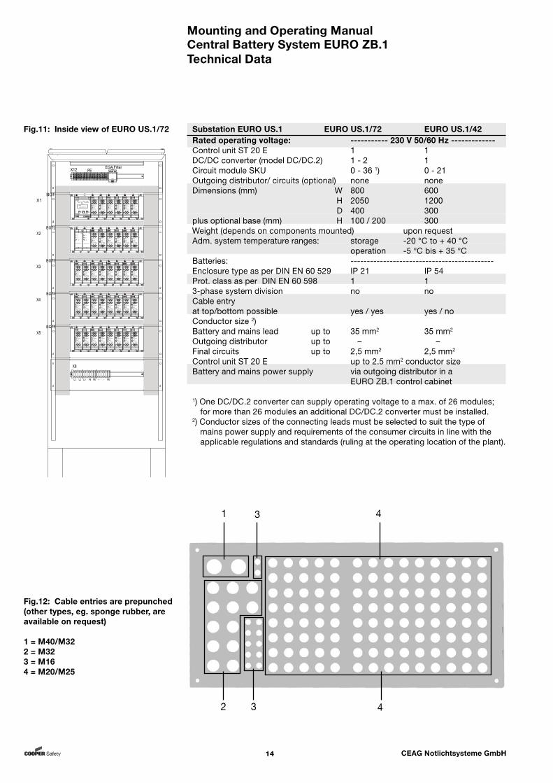
Substation EURO US.1 EURO US.1/72 EURO US.1/42Rated operating voltage: ----------- 230 V 50/60 Hz -------------Control unit ST 20 E 1 1DC/DC converter (model DC/DC.2) 1 - 2 1 Circuit module SKU 0 - 36 1) 0 - 21 Outgoing distributor/ circuits (optional) none noneDimensions (mm) W 800 600 H 2050 1200 D 400 300plus optional base (mm) H 100 / 200 300Weight (depends on components mounted) upon request Adm. system temperature ranges: storage -20 °C to + 40 °C operation -5 °C bis + 35 °C Batteries: --------------------------------------------Enclosure type as per DIN EN 60 529 IP 21 IP 54Prot. class as per DIN EN 60 598 1 13-phase system division no noCable entryat top/bottom possible yes / yes yes / noConductor size 2) Battery and mains lead up to 35 mm2 35 mm2
Outgoing distributor up to – – Final circuits up to 2,5 mm2 2,5 mm2 Control unit ST 20 E up to 2.5 mm2 conductor size Battery and mains power supply via outgoing distributor in a EURO ZB.1 control cabinet
1) One DC/DC.2 converter can supply operating voltage to a max. of 26 modules; for more than 26 modules an additional DC/DC.2 converter must be installed.
2) Conductor sizes of the connecting leads must be selected to suit the type of mains power supply and requirements of the consumer circuits in line with the applicable regulations and standards (ruling at the operating location of the plant).
Technical Data
Fig.11: Inside view of EURO US.1/72
Fig.12: Cable entries are prepunched (other types, eg. sponge rubber, are available on request)
1 = M40/M322 = M323 = M164 = M20/M25
1 3
2 3
4
4

Mounting and Operating ManualCentral Battery System EURO ZB.1
15 CEAG Notlichtsysteme GmbH
Technical Data
Substation EURO US.1 EURO US.1/26 /10 /ESF-E30/179 ESF-E30/289 Rated operating voltage: -------------------------- 230 V 50/60 Hz ------------------------Control unit ST 20 E 1 1 1 1DC/DC converter (model DC/DC.2) 1 1 1 1Circuit module SKU 0 - 13 0 - 5 0 - 17 0 - 26Outgoing distributor/ circuits none none none noneDimensions (mm) W 600 400 885 885 H 800 600 1150 2190 D 250 250 405 405plus optional base (mm) H – – – – Weight (depending on components mounted) upon request Adm. system temperature range: storage -20 °C to + 40 °C operation -5 °C to + 35 °C Batteries: -----------------------------------------------------------------------------Enclosure type as per DIN EN 60 529 IP 54 IP 54 IP 54 IP 54Protection class as per DIN EN 60 598 1 1 1 13-phase system division no no no noCable entryat top/bottom possible yes / no yes / no yes / no yes / noConductor size 2) Battery and mains lead up to 35 mm2 16 mm2 16 mm2 16 mm²Outgoing distributor up to – – – –Final circuits up to 2,5 mm2 2,5 mm2 4,0 mm² 4,0 mm²Control unit ST 20 E up to 2.5 mm2 conductor size up to 4,0 mm² conductor sizeBattery and mains power supply via outgoing distributors in a EURO ZB.1 control cabinet
The technical data apply to a nominal temperature of +20 °C.
2) Conductor sizes of the connecting leads must be selected to suit the type of mains power supply and requirements of the consumer circuits in line with the applicable regulations and standards (ruling at the operating location of the plant).
4) E30 means fire protection class 30 prescribing functions to be maintained for at least 30 minutes (verified by a state-certified materials testing institute of the Federal Republic of Germany based on DIN 4102 part 2 and part 12).
9) With general technical approval Z-86.2-1. Please note that for assembling of ESF-E30 cabinets a massive wall with min. 30 minutes fire resistance is necessary.
Attention! When planning the equipment and during subsequent operation make sure that
the systems are sufficiently cooled (compare remarks under „Adm. temperature ranges“),
environmental requirements are met as per type of enclosure and protection class (regarding protection against contact with live components and ingress of dust, foreign materials or moisture),
the line length of a lighting circuit up to the last luminaire of the circuit does not exceed the admissible line length.
Mounting and Operating ManualCentral Battery System EURO ZB.1
16 CEAG Notlichtsysteme GmbH
CEAG offers battery cabinets of various sizes and accommodating various compo-nents. Low-maintenance batteries according to EUROBAT standard are provided the service life of 10 years if handled and operated properly and with circum-spection. Regarding design and type these CEAG approved batteries meet all the requirements applicable in the Federal Republic of Germany to safety lighting systems prescribed by building laws (EN 50272 and EN 60896-2). In this context our operating instructions for battery cabinets 300 80 001 441 and for battery racks 300 80 001 442 must also be observed.
CEAG standard battery cabinets
Capacity range 23.3 to 354 Ah 1)Rated voltage 216 V DCDimensions (depends on type) vary 2)Weight (depends on type) varies 2)
CEAG compact battery cabinets
Capacity range 5.5 to 89.4 AhRated voltage 216 V DCDimensions (depends on type) vary 2)Weight (depends on type) varies 2)
CEAG-Batteriegestelle
Capacity range 23.3 to 354 Ah 1)Rated voltage 216 V DCDimensions (depends on type) vary 3)Weight (depends on type) varies 3)
Battery operating temperature
The optimum operating temperature is +20 °C. Niedrigere Lower temperatures will impair the available capacity. Higher temperatures will reduce the usability period. The technical data apply to a nominal temperature of +20 °C. In this context our operating instructions for battery cabinets 300 80 001 441 and for battery racks 300 80 001 442 must also be observed.
1) By connecting several battery sets in parallel battery capacities exceeding 118 Ah can be obtained.
2) See CEAG Installation Instructions for battery cabinets (300 80 001 441) 3) See CEAG Installation Instructions for battery racks (300 80 001 442)
4 Batteries for Emergency Power Supply
Batteries
Mounting and Operating ManualCentral Battery System EURO ZB.1
17 CEAG Notlichtsysteme GmbH
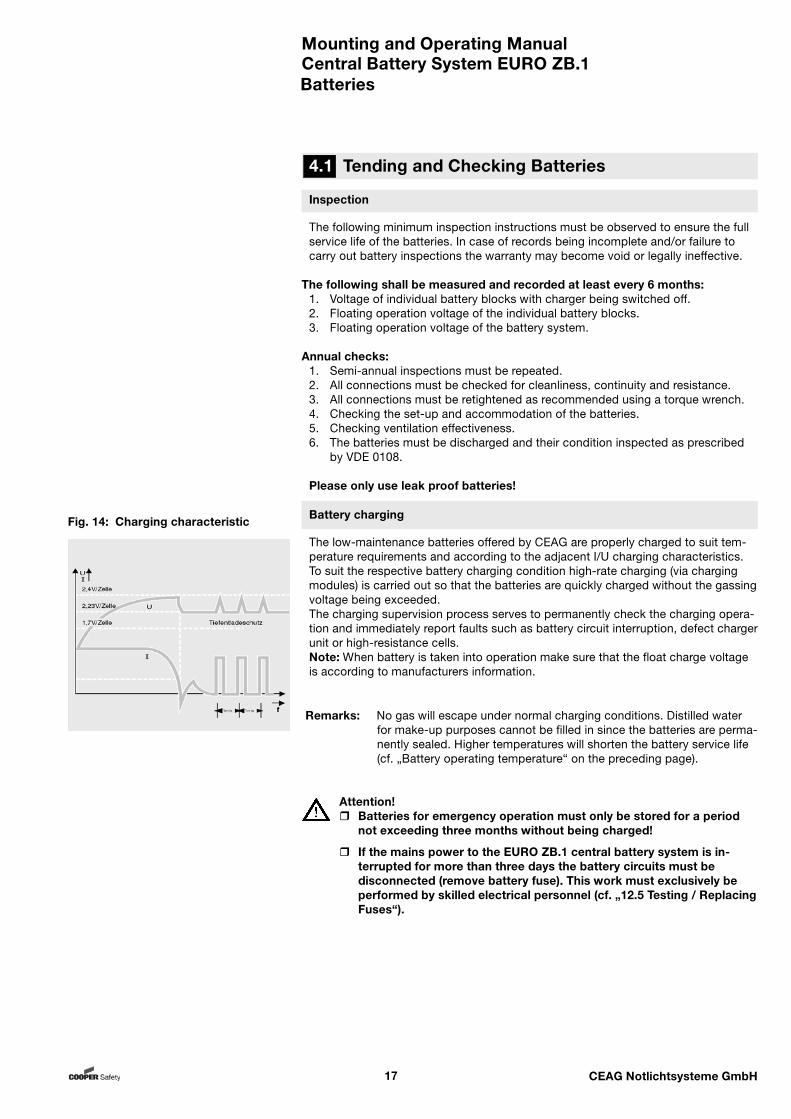
Fig. 14: Charging characteristic
Remarks: No gas will escape under normal charging conditions. Distilled water for make-up purposes cannot be filled in since the batteries are perma-nently sealed. Higher temperatures will shorten the battery service life (cf. „Battery operating temperature“ on the preceding page).
Attention! Batteries for emergency operation must only be stored for a period
not exceeding three months without being charged!
If the mains power to the EURO ZB.1 central battery system is in-terrupted for more than three days the battery circuits must be disconnected (remove battery fuse). This work must exclusively be performed by skilled electrical personnel (cf. „12.5 Testing / Replacing Fuses“).
4.1 Tending and Checking Batteries
Batteries
Inspection
The following minimum inspection instructions must be observed to ensure the full service life of the batteries. In case of records being incomplete and/or failure to carry out battery inspections the warranty may become void or legally ineffective.
The following shall be measured and recorded at least every 6 months:1. Voltage of individual battery blocks with charger being switched off.2. Floating operation voltage of the individual battery blocks.3. Floating operation voltage of the battery system.
Annual checks:1. Semi-annual inspections must be repeated.2. All connections must be checked for cleanliness, continuity and resistance.3. All connections must be retightened as recommended using a torque wrench.4. Checking the set-up and accommodation of the batteries.5. Checking ventilation effectiveness.6. The batteries must be discharged and their condition inspected as prescribed by VDE 0108.
Please only use leak proof batteries!
Battery charging
The low-maintenance batteries offered by CEAG are properly charged to suit tem-perature requirements and according to the adjacent I/U charging characteristics. To suit the respective battery charging condition high-rate charging (via charging modules) is carried out so that the batteries are quickly charged without the gassing voltage being exceeded.The charging supervision process serves to permanently check the charging opera-tion and immediately report faults such as battery circuit interruption, defect charger unit or high-resistance cells.Note: When battery is taken into operation make sure that the float charge voltage is according to manufacturers information.

Mounting and Operating ManualCentral Battery System EURO ZB.1
18 CEAG Notlichtsysteme GmbH
Modules
5 Modules Functioning
5.1 Functions of Batterie Control Modul BCM
5.2 Functions of Charging Modules CM 1,7 A and CM 3,4 A
Indicators ON LED The LED lights up when the BCM is in operation. If the LED does not light up then the BCM is faulty or there is no mains supply or a function test has been triggered. Boost Charge LED The Boost Charge LED lights up during boost charging, e. g. following a mains failure or operating duration test. Charge Fault LED The light emitting diode charge fault lights up when the BCM, the charge booster CM 1.7 A and CM 3.4 A or the batteries are faulty. Further error messages can be queried via the control unit. With faults of the CM 1.7 and 3.4 A modules, error display relates to the module address. ISO-Failure LED The Light emitting diode ISO-Failure lights up when an isolation fault exists in the battery circuit.
Connection terminalsThe terminals are of the push-lock type.The terminals can be unplugged to assist installation.
Potential-free signal contacts Potential-free signals can be relayed with terminals „11-12“, „21-22“, „31-32“. The contact 11/12 is closed in the event of fault. The contact 21/22 is closed in the event of an insulation failure. The contact 31/32 is closed during boost charging. Temperature sensor An external temperature sensor must be connected to terminals F+ and F-. The temperature sensor must be connected using a screened 2-core cable. A conductor size of 0.5 mm² is adequate for cable runs < 50 m as the measuring current is very low. measurement of battery current Battery current is measured via a measuring shunt via terminals I+, I-. CCB bus connection terminals for charging boosters CM 1.7 A and CM 3.4 A The Charge Control Bus (terminals CCB +, CCB -) controls and monitors the charging boosters CM 1.7 A and CM 3.4 A. Terminals + - BST 2.5 A boosters are controlled via the terminals. Terminals + - 24V The BCM module is supplied via the DC/DC converter .2 via the terminals. Attention!The CCB bus is not designed as a SELV system. The bus components must be handled as if mains supply (240V) is applied.
A suitable number of charge modules should be planned for complying
with the legislative recharging duration for the planned battery sets.
The CM modules have their own calibrated charge control and also
function independently of the BCM. With integrated fan monitoring.
Mounting and Operating ManualCentral Battery System EURO ZB.1
19 CEAG Notlichtsysteme GmbH
Additional features:
External 24 V– 20 W continuous rating– Output via front-side plug– Voltage electrically isolated
Internal 24 V– 100 W continuous rating– 140 W Peak rating (20 msec.)– Feeding a maximum of 26 SKU
Connection in parallelpossible for several converters!
Feed-in via AC/AC converterpossible to enable external mains supply.
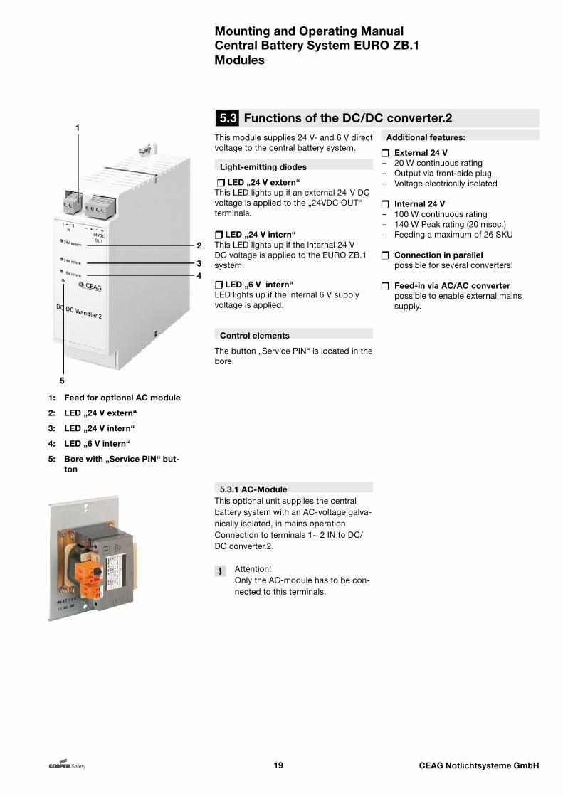
This module supplies 24 V- and 6 V direct voltage to the central battery system.
Light-emitting diodes
LED „24 V extern“This LED lights up if an external 24-V DC voltage is applied to the „24VDC OUT“ terminals.
LED „24 V intern“This LED lights up if the internal 24 V DC voltage is applied to the EURO ZB.1 system.
LED „6 V intern“LED lights up if the internal 6 V supply voltage is applied.
Control elements
The button „Service PIN“ is located in the bore.
5.3.1 AC-ModuleThis optional unit supplies the central battery system with an AC-voltage galva-nically isolated, in mains operation.Connection to terminals 1~ 2 IN to DC/DC converter.2.
Attention! Only the AC-module has to be con- nected to this terminals.
Modules
5.3 Functions of the DC/DC converter.21
2
34
5
1: Feed for optional AC module
2: LED „24 V extern“
3: LED „24 V intern“
4: LED „6 V intern“
5: Bore with „Service PIN“ but-ton
Mounting and Operating ManualCentral Battery System EURO ZB.1
20 CEAG Notlichtsysteme GmbH
Modules
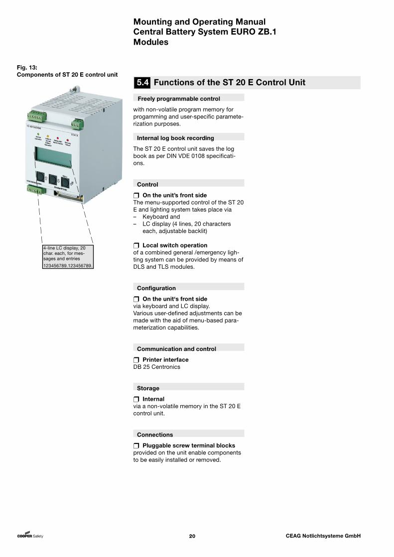
Freely programmable control
with non-volatile program memory for progamming and user-specific paramete-rization purposes.
Internal log book recording
The ST 20 E control unit saves the log book as per DIN VDE 0108 specificati-ons.
Control
On the unit’s front sideThe menu-supported control of the ST 20 E and lighting system takes place via– Keyboard and– LC display (4 lines, 20 characters
each, adjustable backlit) Local switch operationof a combined general /emergency ligh-ting system can be provided by means of DLS and TLS modules.
Configuration
On the unit‘s front side via keyboard and LC display. Various user-defined adjustments can be made with the aid of menu-based para-meterization capabilities.
Communication and control
Printer interfaceDB 25 Centronics
Storage
Internalvia a non-volatile memory in the ST 20 E control unit.
Connections
Pluggable screw terminal blocksprovided on the unit enable components to be easily installed or removed.
Fig. 13: Components of ST 20 E control unit
4-line LC display, 20 char. each, for mes-sages and entries
123456789.123456789.
5.4 Functions of the ST 20 E Control Unit
Mounting and Operating ManualCentral Battery System EURO ZB.1
21 CEAG Notlichtsysteme GmbH
Notes:In the development and advance-ment of modules for a system family (in this case the SKU modules for the EURO ZB.1 system) CEAG-Not-lichtsysteme GmbH takes measures to ensure downward compatibility with respect to the control software of the modules, their application and control. When using modules of current development status as well as modules of older design always observe for safety reasons the tech-nical documentation accompanying these modules.
In case of doubt contact the Customer Service of CEAG Not-lichtsysteme GmbH.
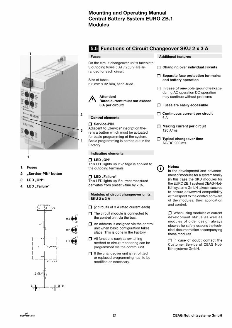
Fuses
On the circuit changeover unit’s faceplate 3 outgoing fuses 5 AT / 250 V are ar-ranged for each circuit.
Size of fuses: 6.3 mm x 32 mm, sand-filled.
Attention! Rated current must not exceed 3 A per circuit!
Control elements
Service-PINAdjacent to „Service“ inscription the-re is a button which must be actuated for basic programming of the system. Basic programming is carried out in the Factory.
Indicating elements
LED „ON“This LED lights up if voltage is applied to the outgoing terminals.
LED „Failure“This LED lights up if current measured derivates from preset value by x %.
Additional features
Changing over individual circuits
Separate fuse protection for mains and battery operation
In case of one-pole ground leakage during AC operation DC operation may continue without problems
Fuses are easily accessible
Continuous current per circuit 6 A
Making current per circuit 120 A/ms
Typical changeover time AC/DC 200 ms
Modules of circuit changeover units SKU 2 x 3 A
(2 circuits of 3 A rated current each)
The circuit module is connected to the control unit via the bus.
An address is assigned via the control unit when basic configuration takes place. This is done in the Factory.
All functions such as switching method or circuit monitoring can be programmed via the control unit.
If the changeover unit is retrofitted or replaced programming has to be modified as necessary.
Modules
5.5 Functions of Circuit Changeover SKU 2 x 3 A
1: Fuses
2: „Service-PIN“ button
3: LED „ON“
4: LED „Failure“
1
1
2
3
4
Mounting and Operating ManualCentral Battery System EURO ZB.1
22 CEAG Notlichtsysteme GmbH
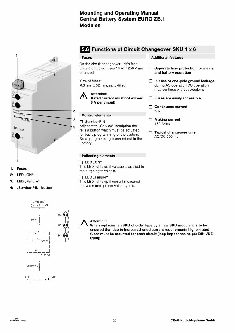
Fuses
On the circuit changeover unit’s face-plate 3 outgoing fuses 10 AT / 250 V are arranged.
Size of fuses: 6.3 mm x 32 mm, sand-filled.
Attention! Rated current must not exceed 6 A per circuit!
Control elements
Service-PINAdjacent to „Service“ inscription the-re is a button which must be actuated for basic programming of the system. Basic programming is carried out in the Factory.
Indicating elements
LED „ON“This LED lights up if voltage is applied to the outgoing terminals.
LED „Failure“This LED lights up if current measured derivates from preset value by x %.
Additional features
Separate fuse protection for mains and battery operation
In case of one-pole ground leakage during AC operation DC operation may continue without problems
Fuses are easily accessible
Continuous current 6 A
Making current 180 A/ms
Typical changeover time AC/DC 200 ms
Modules
Attention!When replacing an SKU of older type by a new SKU module it is to be ensured that due to increased rated current requirements higher-rated fuses must be mounted for each circuit (loop impedance as per DIN VDE 0100)!
5.6 Functions of Circuit Changeover SKU 1 x 6
1: Fuses
2: LED „ON“
3: LED „Failure“
4: „Service-PIN“ button
1
1
2
3
4
Mounting and Operating ManualCentral Battery System EURO ZB.1
23 CEAG Notlichtsysteme GmbH
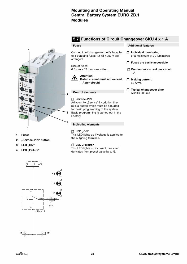
Fuses
On the circuit changeover unit’s facepla-te 8 outgoing fuses 1.6 AT / 250 V are arranged.
Size of fuses: 6.3 mm x 32 mm, sand-filled.
Attention! Rated current must not exceed 1 A per circuit!
Control elements
Service-PINAdjacent to „Service“ inscription the-re is a button which must be actuated for basic programming of the system. Basic programming is carried out in the Factory.
Indicating elements
LED „ON“This LED lights up if voltage is applied to the outgoing terminals.
LED „Failure“This LED lights up if current measured derivates from preset value by x %.
Additional features
Individual monitoring of a maximum of 20 luminaires
Fuses are easily accessible
Continuous current per circuit 1 A
Making current 60 A/ms
Typical changeover time AC/DC 200 ms
5.7 Functions of Circuit Changeover SKU 4 x 1 A
Modules
1: Fuses
2: „Service-PIN“ button
3: LED „ON“
4: LED „Failure“
1
2
3
4
1
1,6 A
Mounting and Operating ManualCentral Battery System EURO ZB.1
24 CEAG Notlichtsysteme GmbH
Modules
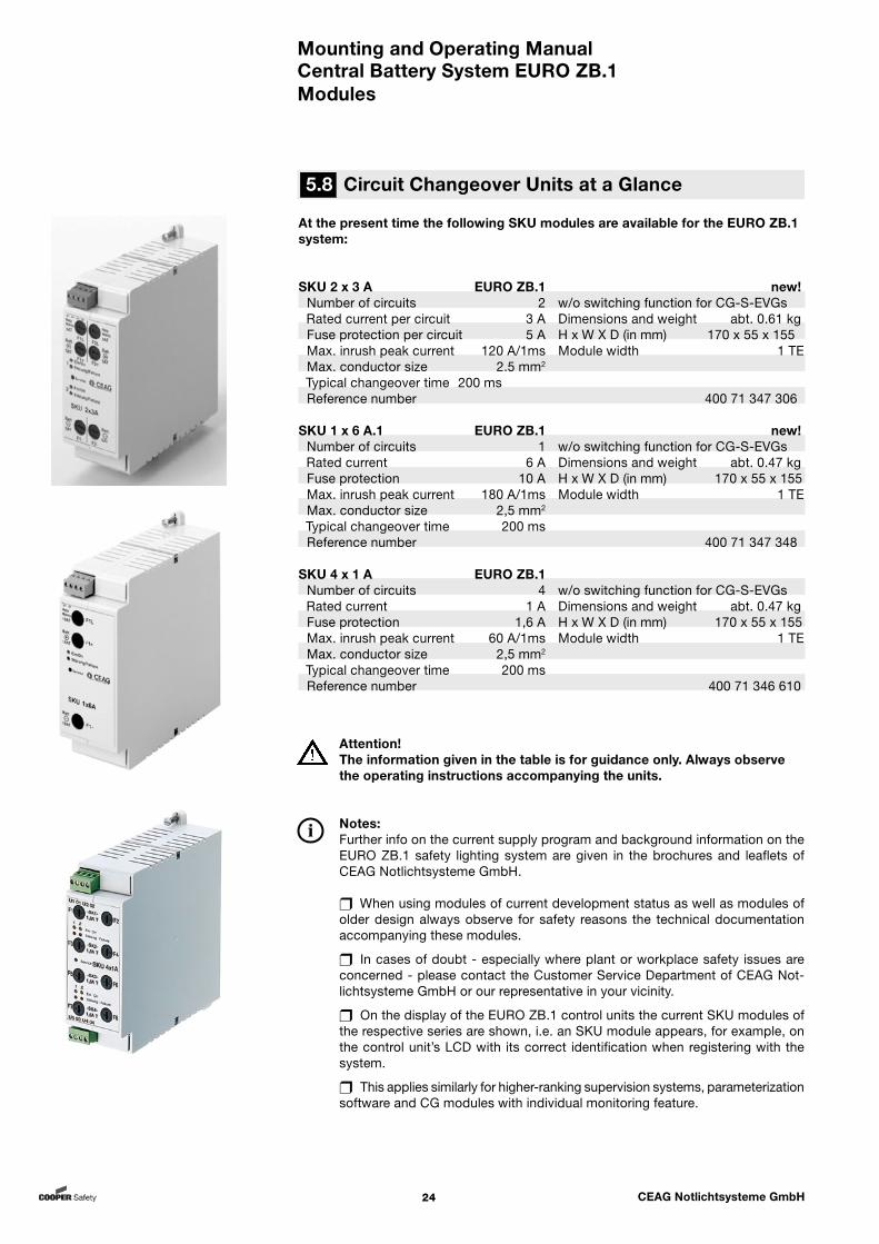
At the present time the following SKU modules are available for the EURO ZB.1 system:
SKU 2 x 3 A EURO ZB.1 new!
Number of circuits 2 w/o switching function for CG-S-EVGs Rated current per circuit 3 A Dimensions and weight abt. 0.61 kgFuse protection per circuit 5 A H x W X D (in mm) 170 x 55 x 155 Max. inrush peak current 120 A/1ms Module width 1 TE Max. conductor size 2.5 mm2
Typical changeover time 200 msReference number 400 71 347 306
SKU 1 x 6 A.1 EURO ZB.1 new!Number of circuits 1 w/o switching function for CG-S-EVGs
Rated current 6 A Dimensions and weight abt. 0.47 kgFuse protection 10 A H x W X D (in mm) 170 x 55 x 155 Max. inrush peak current 180 A/1ms Module width 1 TEMax. conductor size 2,5 mm2
Typical changeover time 200 msReference number 400 71 347 348
SKU 4 x 1 A EURO ZB.1 Number of circuits 4 w/o switching function for CG-S-EVGs
Rated current 1 A Dimensions and weight abt. 0.47 kgFuse protection 1,6 A H x W X D (in mm) 170 x 55 x 155 Max. inrush peak current 60 A/1ms Module width 1 TEMax. conductor size 2,5 mm2
Typical changeover time 200 msReference number 400 71 346 610
Attention!The information given in the table is for guidance only. Always observe the operating instructions accompanying the units.
Notes:Further info on the current supply program and background information on the EURO ZB.1 safety lighting system are given in the brochures and leaflets of CEAG Notlichtsysteme GmbH. When using modules of current development status as well as modules of older design always observe for safety reasons the technical documentation accompanying these modules.
In cases of doubt - especially where plant or workplace safety issues are concerned - please contact the Customer Service Department of CEAG Not-lichtsysteme GmbH or our representative in your vicinity.
On the display of the EURO ZB.1 control units the current SKU modules of the respective series are shown, i.e. an SKU module appears, for example, on the control unit’s LCD with its correct identification when registering with the system.
This applies similarly for higher-ranking supervision systems, parameterization software and CG modules with individual monitoring feature.
5.8 Circuit Changeover Units at a Glance
Mounting and Operating ManualCentral Battery System EURO ZB.1
25 CEAG Notlichtsysteme GmbH
Description
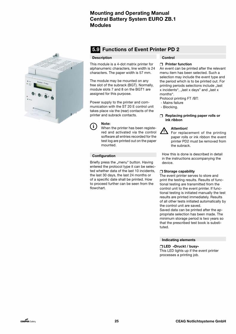
This module is a 4-dot matrix printer for alphanumeric characters, line width is 24 characters. The paper width is 57 mm.
The module may be mounted on any free slot of the subrack (BGT). Normally, module slots 7 and 8 on the BGT1 are assigned for this purpose.
Power supply to the printer and com-munication with the ST 20 E control unit takes place via the (rear) contacts of the printer and subrack contacts.
Note:When the printer has been registe-red and activated via the control software all entries recorded for the test log are printed out on the paper mounted.
Configuration
Briefly press the „menu“ button. Having entered the protocol type it can be selec-ted whether data of the last 10 incidents, the last 30 days, the last 24 months or of a specific date shall be printed. How to proceed further can be seen from the flowchart.
Control
Printer functionAn event can be printed after the relevant menu item has been selected. Such a selection may include the event type and the period which is to be printed out. For printing periods selections include „last x incidents“, „last x days” and „last x months“.Protocol printing FT /BT: - Mains failure - Blocking.
Replacing printing paper rolls or ink ribbon
Attention!For replacement of the printing paper rolls or ink ribbon the event printer PD2 must be removed from the subrack.
How this is done is described in detail in the instructions accompanying the device.
Storage capabilityThe event printer serves to store and print the testing results. Results of func-tional testing are transmitted from the control unit to the event printer. If func-tional testing is initiated manually the test results are printed immediately. Results of all other tests initiated automatically by the control unit are saved.Saved data can be printed after the ap-propriate selection has been made. The minimum storage period is two years so that the prescribed test book is substi-tuted.
Indicating elements
LED «Druckt / busy»This LED lights up if the event printer processes a printing job.
Modules
5.9 Functions of Event Printer PD 2
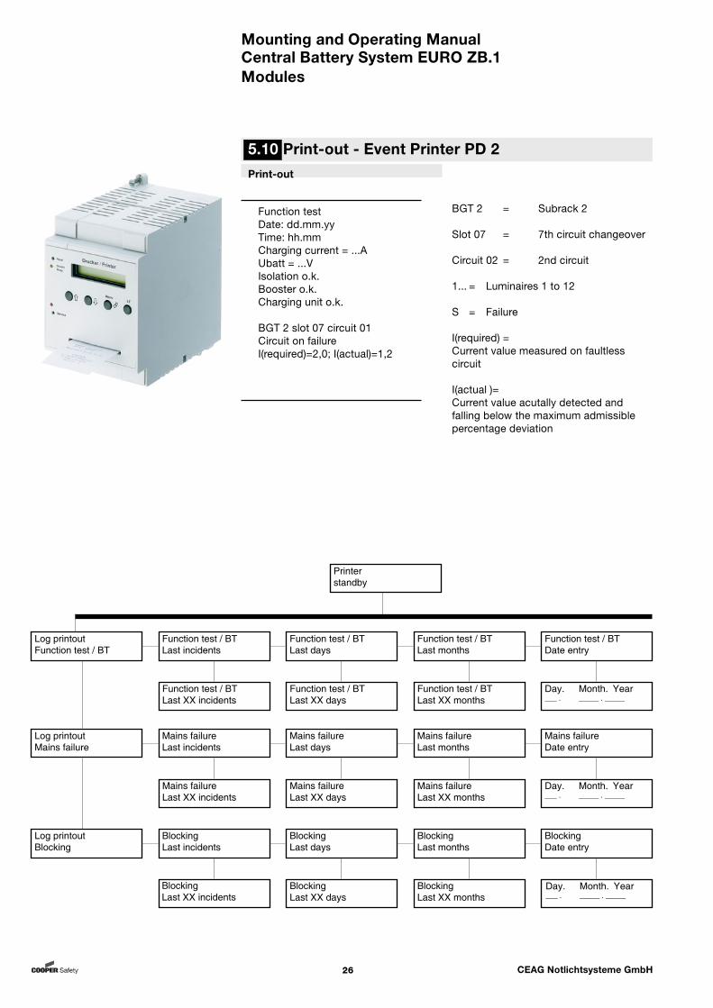
Mounting and Operating ManualCentral Battery System EURO ZB.1
26 CEAG Notlichtsysteme GmbH
Print-out
Function test Date: dd.mm.yy Time: hh.mm Charging current = ...A Ubatt = ...V Isolation o.k. Booster o.k. Charging unit o.k. BGT 2 slot 07 circuit 01 Circuit on failure
I(required)=2,0; I(actual)=1,2
Modules
5.10 Print-out - Event Printer PD 2
BGT 2 = Subrack 2
Slot 07 = 7th circuit changeover
Circuit 02 = 2nd circuit
1... = Luminaires 1 to 12
S = Failure
I(required) = Current value measured on faultless circuit
I(actual )=Current value acutally detected andfalling below the maximum admissiblepercentage deviation
Printerstandby
Log printoutFunction test / BT
Log printoutMains failure
Log printoutBlocking
Function test / BTLast incidents
Function test / BTLast days
Function test / BTLast months
Function test / BTDate entry
Function test / BTLast XX incidents
Function test / BTLast XX days
Function test / BTLast XX months
Day. Month. Year___ . _____ . _____
Mains failureLast incidents
Mains failureLast days
Mains failureLast months
Mains failureDate entry
Mains failureLast XX incidents
Mains failureLast XX days
Mains failureLast XX months
Day. Month. Year___ . _____ . _____
BlockingLast incidents
BlockingLast days
BlockingLast months
BlockingDate entry
BlockingLast XX incidents
BlockingLast XX days
BlockingLast XX months
Day. Month. Year___ . _____ . _____
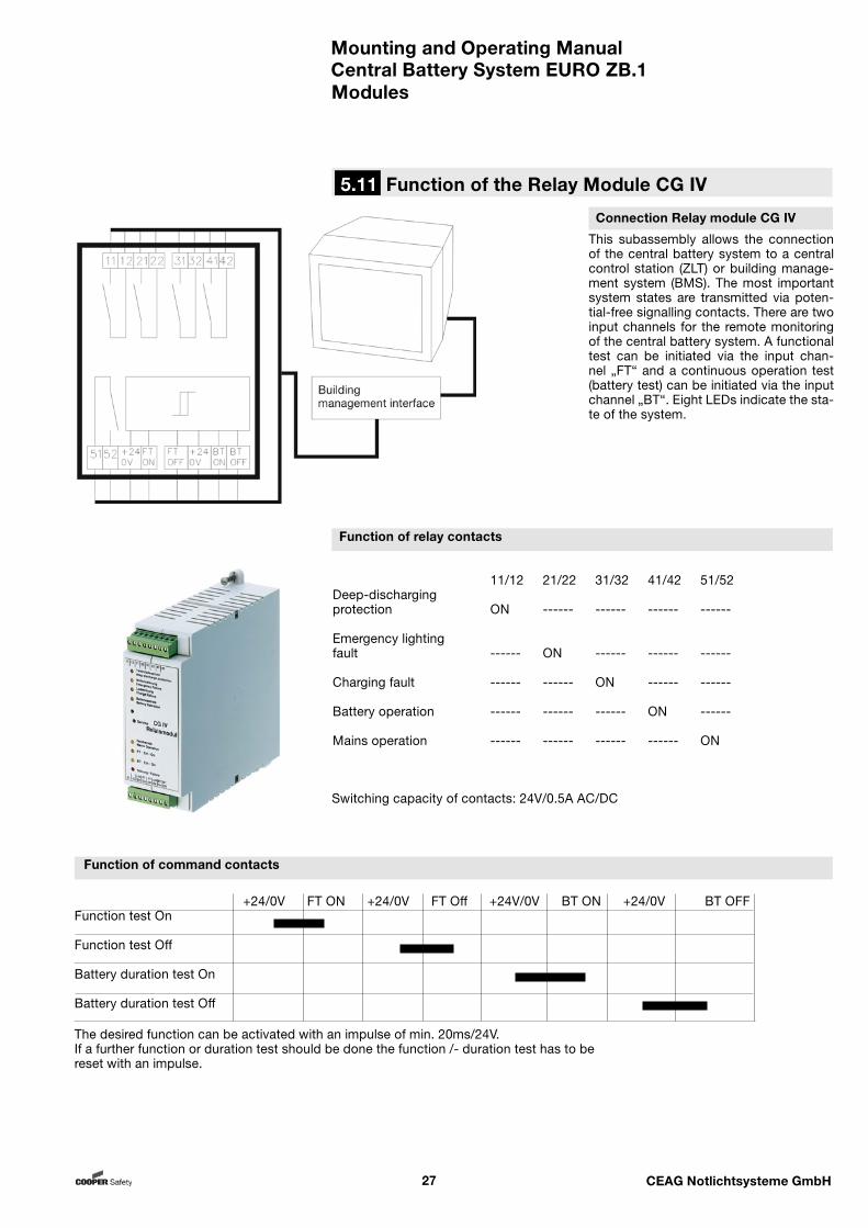
Mounting and Operating ManualCentral Battery System EURO ZB.1
27 CEAG Notlichtsysteme GmbH
+24/0V FT ON +24/0V FT Off +24V/0V BT ON +24/0V BT OFF Function test On
Function test Off
Battery duration test On
Battery duration test Off
5.11 Function of the Relay Module CG IV
Modules
This subassembly allows the connection of the central battery system to a central control station (ZLT) or building manage-ment system (BMS). The most important system states are transmitted via poten-tial-free signalling contacts. There are two input channels for the remote monitoring of the central battery system. A functional test can be initiated via the input chan-nel „FT“ and a continuous operation test (battery test) can be initiated via the input channel „BT“. Eight LEDs indicate the sta-te of the system.
11/12 21/22 31/32 41/42 51/52Deep-discharging protection ON ------ ------ ------ ------
Emergency lighting fault ------ ON ------ ------ ------
Charging fault ------ ------ ON ------ ------
Battery operation ------ ------ ------ ON ------
Mains operation ------ ------ ------ ------ ON
The desired function can be activated with an impulse of min. 20ms/24V.If a further function or duration test should be done the function /- duration test has to be reset with an impulse.
Connection Relay module CG IV
Function of relay contacts
Function of command contacts
Switching capacity of contacts: 24V/0.5A AC/DC

Mounting and Operating ManualCentral Battery System EURO ZB.1
28 CEAG Notlichtsysteme GmbH
TLS switching module
If general and safety luminaires are to be controlled by the same buttons (without additional installation expense) a TLS switching module can be mounted in the lighting distribution systems. Control is effected via a circuit changeover unit (SKU).
Technical Data
Connection– Terminals: 2.5 mm²– Dimensions (H x W x D) mm:
84 x 52 x 64
Switching capacity– 3 x 16 A
Note: As regards planning and use of the module please refer to the technical documentation supplied with the modules and brochures and leaflets of CEAG Notlichtsy-steme GmbH.
Description
This module enables time-controlled switching (1 to 15 minutes) of the final circuits during mains and battery opera-tion.Via the TLSs input channels up to eight button circuits can be queried. Via an inverter arranged in the module the illu-minated buttons are powered in mains as well as battery operation. The number of buttons that can be connected has been indicated in the table below. A maximum of one input channel of the TLS can be assigned to each final circuit via the freely programmable control unit of the EURO ZB.1.
Technical Data
Connections– Terminals 2.5 mm², rigid and flexible
Button inputs – Max. 8 button inputs with:– 1 mA glow lamp 50 pcs.– 0,8 mA glow lamp 62 pcs.– 0,4 mA glow lamp 125 pcs.per button input
Item 1: top terminal stripItem 2: bottom terminal stripItem 3: Indicating LEDs LED „Störung / Failure“ lights up if a fault has been detected in the moduleItem 4: Fixing element (fastening screw) for the module.
1 2 3 4
Modules
5.12 Functions of the TLS Switching Module

Mounting and Operating ManualCentral Battery System EURO ZB.1
29 CEAG Notlichtsysteme GmbH
Application:
Installation in the EURO ZB.1 (EURO US.1) control cabinet
to facilitate maintenance efforts
Notes: Please observe info on bus technology and shielding as de-tailed on the following pages.
As regards planning and use of the module please refer to the tech-nical documentation supplied with the modules and brochures and leaflets of CEAG Notlicht-systeme GmbH.
1 2 3 4
Item 1: top terminal strip for (moni-toring) inputsItem 2: bottom terminal stripItem 3: Indicating LEDs LEDs 1 ... 8 light up if the circuit is closed or the monitored supply volta-ge is applied, LED „Störung / Failure“ lights up if a fault is detected in the moduleItem 4: Fixing element (fastening screw) for the module.
Modules
5.13 Functions of Permanent Light Switch Checking DLS
Description
This electronic monitoring module serves for (light) switch checking purposes. During mains operation luminaires of the general and safety lighting systems are switched in line with switch positions and adjustments of the EURO ZB.1 control unit. During emergency operation (eg. after monitored phases of the mains power supply system have failed) the circuits of the safety lighting system are operated as per the settings made on the EURO ZB.1 control unit.
Technical Data
Connection– Terminals 2.5 mm², rigid and flexible.
Number of light switch inputs– up to 8, electrically isolated– Rated voltage Un = 230 V
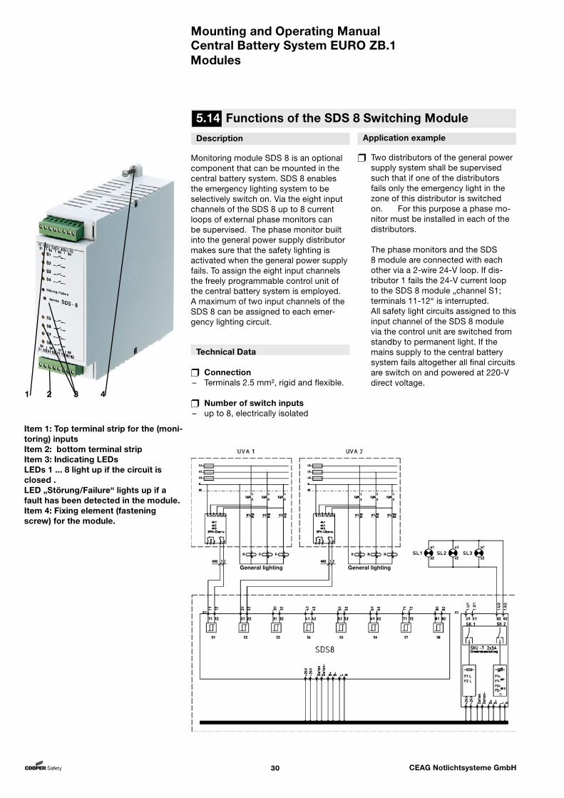
Mounting and Operating ManualCentral Battery System EURO ZB.1
30 CEAG Notlichtsysteme GmbH
Description
Monitoring module SDS 8 is an optional component that can be mounted in the central battery system. SDS 8 enables the emergency lighting system to be selectively switch on. Via the eight input channels of the SDS 8 up to 8 current loops of external phase monitors can be supervised. The phase monitor built into the general power supply distributor makes sure that the safety lighting is activated when the general power supply fails. To assign the eight input channels the freely programmable control unit of the central battery system is employed.A maximum of two input channels of the SDS 8 can be assigned to each emer-gency lighting circuit.
Technical Data
Connection– Terminals 2.5 mm², rigid and flexible.
Number of switch inputs– up to 8, electrically isolated
Application example
Two distributors of the general power supply system shall be supervised such that if one of the distributors fails only the emergency light in the zone of this distributor is switched on. For this purpose a phase mo-nitor must be installed in each of the distributors.
The phase monitors and the SDS 8 module are connected with each other via a 2-wire 24-V loop. If dis-tributor 1 fails the 24-V current loop to the SDS 8 module „channel S1; terminals 11-12“ is interrupted.
All safety light circuits assigned to this input channel of the SDS 8 module via the control unit are switched from standby to permanent light. If the mains supply to the central battery system fails altogether all final circuits are switch on and powered at 220-V direct voltage.
1 2 3 4
Item 1: Top terminal strip for the (moni-toring) inputsItem 2: bottom terminal strip Item 3: Indicating LEDs LEDs 1 ... 8 light up if the circuit is closed .LED „Störung/Failure“ lights up if a fault has been detected in the module.Item 4: Fixing element (fastening screw) for the module.
Modules
5.14 Functions of the SDS 8 Switching Module
General lighting General lighting
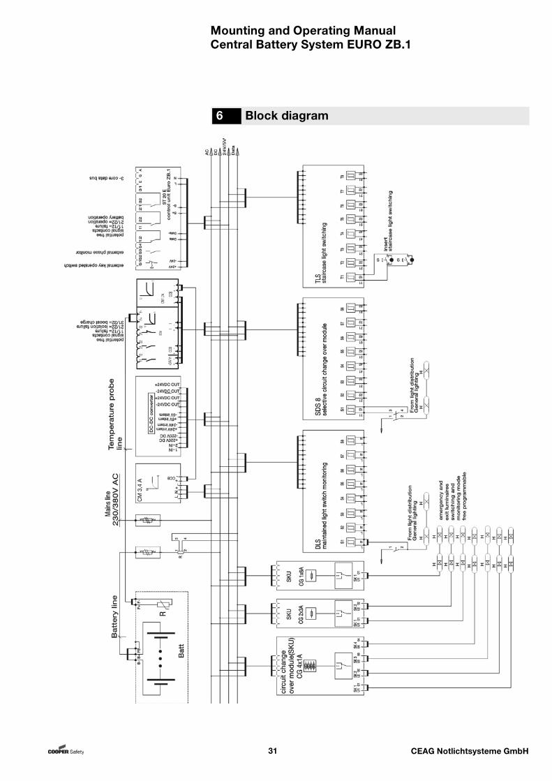
Mounting and Operating ManualCentral Battery System EURO ZB.1
31 CEAG Notlichtsysteme GmbH
6 Block diagram
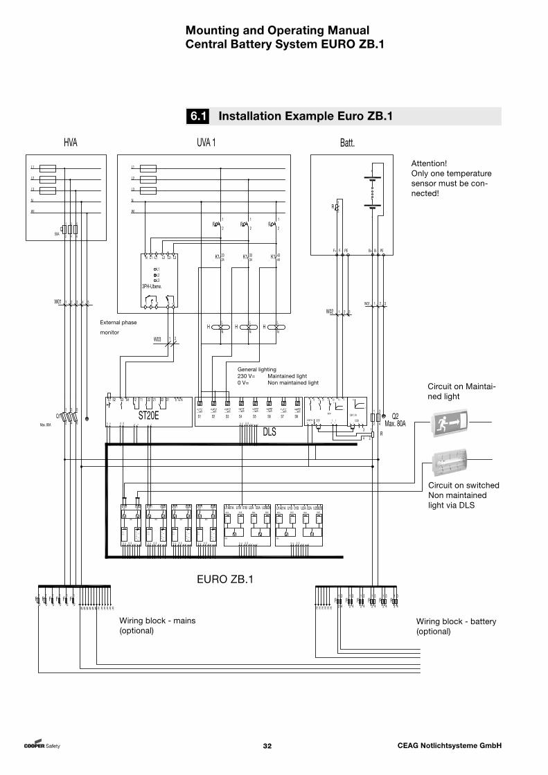
Mounting and Operating ManualCentral Battery System EURO ZB.1
32 CEAG Notlichtsysteme GmbH
General lighting 230 V= Maintained light0 V= Non maintained light
Wiring block - mains(optional)
Wiring block - battery(optional)
External phase
monitor
Attention!Only one temperature sensor must be con-nected!
6.1 Installation Example Euro ZB.1
Circuit on switched Non maintained light via DLS
Circuit on Maintai-ned light
L2
L3
L1
N
PE
HVA
L2
L3
L1
N
PE
UVA 1
2
1F
2
1F
L
NH
L
NH
2
1F
L
NH
1
2
Q50A
3
4 6
5
ST20E
S1 S2 S3 S4 12 11 22 21 32 31 E G A
+24V
-24V
Daten
Daten
-
B+ B- L N
2423K1
./ 3433K1
./ 4443K1
./
S1 S2 S3 S4 S5 S6 S7 S8
L-1 N-1
L-2 N-2
L-3 N-3 L-4 N-4
L-5 N-5
L-6 N-6
L-7 N-7
L-8 N-8
DLS
+24V
-24V
Daten
Daten
-
B+ B- L N
L1L2L3
N L1 L2 L2- L3
1 2 3 S -S
3PH-Uberw.
-L1
Erde
1
2
3
4R
2
1
Q1Max. 80A 4
3
6
5
F1+F1-F2+F2-
=
SK1
SK 2
F1 LF2 L
SK 1 SK 2
SKU
U101 U202
+24V
-24V
Daten
Daten
-
B+ B- L N
U1A01A U1B 01B
+24V
-24V
Daten
Daten
-
B+ B- L N
F1F2
F3F4
F5F6
F7F8
SK1A SK1B SK2A SK2B
SKU
U2A 02A U2B02B U1A01A U1B 01B
+24V
-24V
Daten
Daten
-
B+ B- L N
F1F2
F3F4
F5F6
F7F8
SK1A SK1B SK2A SK2B
SKU
U2A 02A U2B02B
F1+F1-F2+F2-
=
SK1
SK 2
F1 LF2 L
SK 1 SK 2
SKU
U101 U202
+24V
-24V
Daten
Daten
-
B+ B- L N
F1+F1-F2+F2-
=
SK1
SK 2
F1 LF2 L
SK 1 SK 2
SKU
U101 U202
+24V
-24V
Daten
Daten
-
B+ B- L N
F1+F1-F2+F2-
=
SK1
SK 2
F1 LF2 L
SK 1 SK 2
SKU
U101 U202
+24V
-24V
Daten
Daten
-
B+ B- L N
F1
2F
1
2F
1
2F
1
2F
1
2F
1
2N
XX
NX
NX
NX
NX
NX
PEX
PEX
PEX
PEX
PEX
PE
1
2F
3
4
1
2F
3
4
1
2F
3
4
1
2F
3
4
1
2F
3
4
1
2F
3
4X-1
PEX-1
PEX-1
PEX-1
PEX-1
PEX-1
PE
11 12 21 22 31 32 F+
+ - + -
BCM
+24V In
U
t
CCB
CM 1,7A
+ -CCB
+ -
U
t
+ -I I
Batt.
F+ F- PE
1
2R
F-
-
+
-
+
B+ B- PE
1
2Q2
Max. 80A
3
4
Erde
EURO ZB.1
W01 2 3 41 5
W03 1 2
W02 2 31
W02 2 31
EURO ZB.1
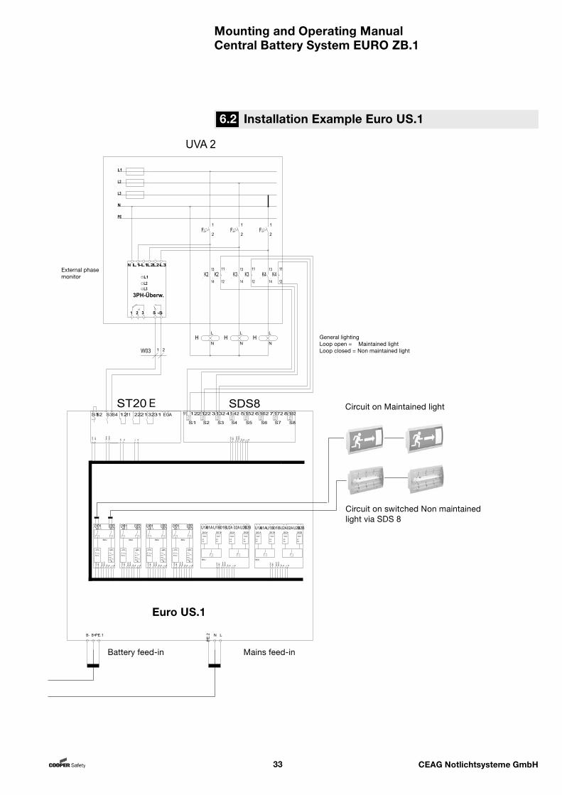
Mounting and Operating ManualCentral Battery System EURO ZB.1
33 CEAG Notlichtsysteme GmbH
6.2 Installation Example Euro US.1
General lightingLoop open = Maintained lightLoop closed = Non maintained light
Circuit on Maintained light
Circuit on switched Non maintained light via SDS 8
Mains feed-inBattery feed-in
External phase monitor
E
Euro US.1
Mounting and Operating ManualCentral Battery System EURO ZB.1
34 CEAG Notlichtsysteme GmbH
7 Important Notes on Safety at Work and Safe Opera-tion of the Emergency Lighting System EURO ZB.1
Important Notes on Safety at Work and Safe Operation of the Emergency Lighting System EURO ZB.1
Warning!This system forms part of the emergency and general lighting equipment and as such is an im-portant safety component of a building or operation. Any unau-thorized or makeshift (inexpert) work carried out on the system may result in a failure of the general or emergency lighting installation and thus cause significant danger to per-
sons,
significant damage to ma-chinery and plant units,
malfunctions and interrupti-on of the production se-quence.
After the system has been mounted, connected and commissioned only the following work is required during normal operation: Monitoring and logging of the system
functions Safeguarding actions in the case of
malfunctions Carrying out inspections and safety
checks prescribed by law and regula-tions
Notes: Observe the national legislati-on and guidelines with respect to the design and control of a plant forming part of general and emer-gency lighting systems.
Observe the national legislati-on and guidelines with respect to inspections and safety checks (eg. for function and operating durati-on testing).
Organization and monitoring of this work is the duty of the safety lighting system owner! The following is to be laid down in writing and the relevant documents must always be available: Type and scope of work Documentation of the work results Responsibility and authorization
regarding work to be performed
– Who is allowed to perform a cer-tain task?
– Who has to monitor the work performed?
Duty to alert (eg. in case of faults or function testing)
Organizational measures when work is carried out on the lighting sytem.This may include, inter alia:– Information and reporting duty
regarding start, duration and end of the work concerned
– Safety measures to be taken during work: e.g. standby lighting, disconnecting the power supply, safeguards to prevent accidental restarting (eg. removing fuses, lock-outs, danger signs)
– Protection and safety equipment for personnel carrying out work on the plant (eg. suitable working clothes and PPE)
– Protection and safety measures to rule out danger caused by neigh-boring plant units (eg. providing safety fences, barriers, securing traffic routes)
Moreover, observe what has been said regarding target groups and use of this Operating Manual under „7 Important Notes“ and „8 Intended Use“.Inspections and safety checks have to be performed exclusively by authorized expert staff that must also issue the re-quired documentation (to satisfy national legislation and rules).
Note:If the safety lighting system or programming requires modificati-on or in the event of safety checks to be performed, please contact the respective branch of CEAG or consult experts of authorized institutes.
Mounting and Operating ManualCentral Battery System EURO ZB.1
35 CEAG Notlichtsysteme GmbH
The central battery systems EURO ZB.1 and EURO US.1 are intended for moni-toring and controlling lighting plants for general and emergency lighting purpo-ses.
The system operates under program control. Setting parameters must exclu-sively be carried out by expert personnel having special knowledge of statutory and technical fundamentals governing the erection and operation of lighting systems.
The system has been designed and built to reflect the latest technical rules with respect to system safety.
The extensive use of electronic devices has significantly increased in the last few years so that the resultant radio interference may cause major problems as every electronic unit, machine or system transmits interfe-rence of various kind. Such interference may cause hazards particularly in highly automated industrial environments. It may lead to malfunc-tions or even failure of entire plant units. Due to superimposition of different kinds of interference the total radiation interfe-rence level will increase and requires sy-stems and components to be protected against electromagnetic impairment. Es-pecially in the field of industrial process technology is instrumentation equipment interference immunity a must. Therefore, all electronic units and appliances must have CE certification.
CEAG products meet the requirements laid down in EU Directives 89/336/EWG (EMC Directive) and 73/23/EWG as amended by the 93/68/EWG Directive (Low Voltage Directive) and are approved to bear the CE symbol. If luminaires with electronic ballasts satisfy the EMC rules interference caused by the high-frequen-cy operation of the ballasts is well within statutory limits. Nevertheless, it cannot be ruled out that electronic devices may be affected in exceptional cases. Basi-cally, only HF paging systems (in the MHz range) must be employed. No reliable operation is possible if inductive paging systems (25-40kHz) are used.
Nevertheless, danger may arise during plant operation to personnel if the safety instructions
are disregarded, if the unit is used for other than the
intended purpose.
Therefore, operate the system and any system component attached only when in perfect technical condition and obser-ve the safety and danger notes included
in this mounting and operating manu-al,
work procedures and safety instruc-tions prescribed by the plant Owner/Operator,
the installation and operating data listed in Chapter 3 „Technical Data“ und in CEAG catalog „Safety Lumin-aires and Safety Lighting Systems“.
Malfunctions that may impede the functioning or safety of the plant must at once be reported to the respective level of the plant management and have to be eliminated without delay.
The working and safety rules and regula-tions are to be observed as laid down in this mounting and operating manual and furthermore as they arise from organizational measures initiated by
the Plant Management as described under– „1 Important Notes“,– „4 Important Notes on Safety
at Work and Safe Operation of the Emergency Lighting System EURO ZB.1“
as well as from the general and specific accident prevention rules and regulations.
CEAG will not assume any warranty or liability for damage or consequential damage occurring as a result of using the system for other than the
intended purpose, disregarding rules and regulations
governing the safe operation of the system,
unauthorized or inexpert modificati-ons to – the connections and settings of the system, – or the programming of the system,
operating devices or device groups in conjunction with the EURO ZB.1 system that are unsuited or not per-mitted.
Intended Use
Attention!CEAG Notlichtsysteme GmbH will not assume any liability and/or warranty for shortcomings relating to the supply and instal-lation of CEAG safety lighting systems and luminaires that may arise due to other stan-dards and regulations prescri-bed for or applicable to overall installation packages of which CEAG products form part. In addition, be sure to ob-serve all laws, standards and guidelines applicable in the country where the equipment is mounted and operated.
Warning!When planning a lighting system of which the EURO ZB.1 sy-stems forms part please check initially whether the planned electrical installations meet the environmental requirements of the respective mounting locati-on. Special ambient conditions (eg. hazardous areas or zones where aggressive atmosphere prevails) call for special equip-ment and installations.
Notes: When using other ballasts plea-se check if they are suitable for sa-fety lighting systems and operation within a EURO ZB.1 system!
The optimum battery operating temperature for emergency lighting supply is +20 °C. Lower temperatures will impair the available capacity. Higher temperatures will reduce the usability period.The technical data apply to a nomi-nal temperature of +20 °C.. Using RCDs in the mains lead with a release current > 30 mA to protect against indirect contact acc. to VDE 100 part 410, please observe that capacitive leakage current can cause fault activations!
8 Intended Use
Mounting and Operating ManualCentral Battery System EURO ZB.1
36 CEAG Notlichtsysteme GmbH
Transport, Storage and Disposal
The batteries for safety lighting purposes are supplied together with the battery cabinets employed. As regards transport and storage of the batteries please follow the instructions issued by the battery manufacturer and instructions for the battery cabinets.
Attention! Batteries for emergency
operation must only be stored for a period not exceeding three months without being charged!
If the mains power to the EURO ZB.1 system is inter-rupted for more than three days the battery circuit must be disconnected (remove battery fuse). This work must exclusively be performed by skilled electrical personnel (cf. „Testing / Replacing Fuses“).
The following must be observed when handling and storing the equipment:
Always handle and store the EURO ZB.1 system in upright position (see markings and tilting indicator on the package).
Observe the technical specifications under „Technical Data“ governing am-bient conditions when handling and storing the system. The storage loca-tion should be dry and clean. Avoid the ingress of dust and moisture and rule out condensate formation due to moisture during transport and storage (cf. data specified under „Technical Data“ with respect to admissible am-bient temperatures, type of enclosure, and protection class).
Make sure that all transportation routes– are unobstructed (sufficient width
and inside height for all handling movements),
– allow for sufficient escape space for persons in case loads tip over or slide off,
– have adequate carrying capability (for load, transport packing and transportation means),
and that the transport routes are sui-ted for the transportation means used with respect to gradient and surface characteristics (eg. non-skid texture, eveness and other obstacles).
Only use– handling means (eg. hoisting cars,
forklift trucks etc.),– lifting tackle (spreader beams,
chains, ropes etc.) – and securing elements (wedges,
squared timber, guide, bracing and safety ropes etc.)
that are in proper technical condition and have adequate carrying capacity.
Observe all instructions regarding handling conditions, transport positi-on, attachment points on the packing and on the unit/control cabinet.
Handling/transportation work must only be performed by personnel familiar with applicable methods and signals and capable of carrying out this work expertly and in compliance with safety rules and regulations.
Disposal: Packing materials are not to
be viewed as garbage but are valuable substances that have to be processed by suitable recycling measures to render them suited for reuse.
Please follow any national gui-delines and provisions gover-ning the disposal of packing material!
Batteries and electronic com-ponents contain substances that cause health and envi-ronmental risk and damage if not disposed of expertly. Therefore, strictly observe the national guidelines and provisi-ons governing the disposal of used batteries and electronic scrap.
CEAG has obtained the recycling certificate issued by INTERSEROH GmbH.
Contract number No. 85405 applies. This ensures that registered packings are utili-zed in terms of material exploitation with the requirements of the Packing Ordinance being fully met. INTERSEROH collecting stations are obliged to dispose of CEAG
packings free of charge.
9 Transport, Storage and Disposal

Mounting and Operating ManualCentral Battery System EURO ZB.1
37 CEAG Notlichtsysteme GmbH
Danger!When batteries or battery-fed parts of the system are impro-perly handled injuries or danger to life may arise due to high cur-rents or electric arcs momen-tarily developing upon battery discharge.It is mandatory that the instruc-tions in this manual relating to disconnection or connection of batteries are strictly obser-ved (cf. Connecting the Battery Power Supply).Make sure polarity is correctly observed when connecting the battery banks (battery cabinets / racks)!
Attention! Short-circuits and wrong
polarity may cause damage to the battery bank or instal-lations of a EURO ZB.1 or EURO US.1 system.
When working on electrical systems (eg. connecting control or signalling lines) or electronic systems (eg. inserting or withdrawing mo-dules in the control cabinet) ESD precautionary measures must be taken!
When delivered to the customer the equipment shown in this mounting and operating manual may differ in terms of modules fitted. Characteristics of customer-specific designs are described in project documents to be ordered sepa-rately.
Warning! Work on the general supply
network and laying of power, signalling and control lines/cabling as well as connec-tion of the battery power supply must only be carried out by skilled electrical per-sonnel.
Take all measures required to warrant safety at the workplace!
Aside from adhering to general technical standards and practices this also applies to the instructions given in Chapters 1 and 7 to 9 of this manual.
Notes! Laying of connecting lines must exclusively be performed in conformity with applicable guide-lines and standards of electrical engineering (eg. DIN VDE 100 standards series).
In addition please observe all national guidelines and provisions ruling in the country where the plant is erected and operated.
Secure all line entry and exit points of the control cabinet by means of M-glands or rubber seals provided for this purpose to prevent mechanical line damage or ingress of moisture.
Only electronic ballasts and luminaires of a rated operating voltage of 230 V AC (50/60 Hz) and 220 V DC must be connected to the outputs for the emergency lighting/final circuits of the EURO ZB.1 system!
Mounting
10 Mounting
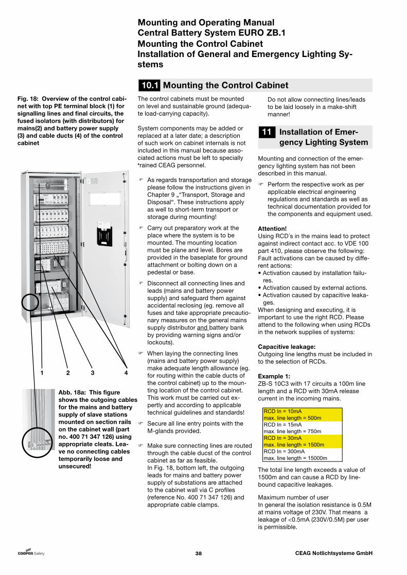
Mounting and Operating ManualCentral Battery System EURO ZB.1
38 CEAG Notlichtsysteme GmbH
Do not allow connecting lines/leads to be laid loosely in a make-shift manner!
Mounting and connection of the emer-gency lighting system has not been described in this manual.
Perform the respective work as per applicable electrical engineering regulations and standards as well as technical documentation provided for the components and equipment used.
Attention!Using RCD´s in the mains lead to protect against indirect contact acc. to VDE 100 part 410, please observe the following: Fault activations can be caused by diffe-rent actions:• Activation caused by installation failu- res.• Activation caused by external actions.• Activation caused by capacitive leaka- ges.When designing and executing, it is important to use the right RCD. Please attend to the following when using RCDs in the network supplies of systems:
Capacitive leakage:Outgoing line lengths must be included in to the selection of RCDs.
Example 1:ZB-S 10C3 with 17 circuits a 100m line length and a RCD with 30mA release current in the incoming mains.
The total line length exceeds a value of 1500m and can cause a RCD by line-bound capacitive leakages.
Maximum number of userIn general the isolation resistance is 0.5M at mains voltage of 230V. That means a leakage of <0.5mA (230V/0.5M) per user is permissible.
The control cabinets must be mounted on level and sustainable ground (adequa-te load-carrying capacity).
System components may be added or replaced at a later date; a description of such work on cabinet internals is not included in this manual because asso-ciated actions must be left to specially trained CEAG personnel.
As regards transportation and storage please follow the instructions given in Chapter 9 „“Transport, Storage and Disposal“. These instructions apply as well to short-term transport or storage during mounting!
Carry out preparatory work at the place where the system is to be mounted. The mounting location must be plane and level. Bores are provided in the baseplate for ground attachment or bolting down on a pedestal or base.
Disconnect all connecting lines and leads (mains and battery power supply) and safeguard them against accidental reclosing (eg. remove all fuses and take appropriate precautio-nary measures on the general mains supply distributor and battery bank by providing warning signs and/or lockouts).
When laying the connecting lines (mains and battery power supply) make adequate length allowance (eg. for routing within the cable ducts of the control cabinet) up to the moun-ting location of the control cabinet.
This work must be carried out ex-pertly and according to applicable technical guidelines and standards!
Secure all line entry points with the M-glands provided.
Make sure connecting lines are routed
through the cable ducst of the control cabinet as far as feasible.
In Fig. 18, bottom left, the outgoing leads for mains and battery power supply of substations are attached to the cabinet wall via C profiles (reference No. 400 71 347 126) and appropriate cable clamps.
Mounting the Control CabinetInstallation of General and Emergency Lighting Sy-stems
Fig. 18: Overview of the control cabi-net with top PE terminal block (1) for signalling lines and final circuits, the fused isolators (with distributors) for mains(2) and battery power supply (3) and cable ducts (4) of the control cabinet
10.1 Mounting the Control Cabinet
11 Installation of Emer-gency Lighting System
RCD In = 10mAmax. line length = 500mRCD In = 15mAmax. line length = 750mRCD In = 30mAmax. line length = 1500mRCD In = 300mAmax. line length = 15000m
trained CEAG personnel.
1 2 3 4
Abb. 18a: This figure shows the outgoing cables for the mains and battery supply of slave stations mounted on section rails on the cabinet wall (part no. 400 71 347 126) using appropriate cleats. Lea-ve no connecting cables temporarily loose and unsecured!

Mounting and Operating ManualCentral Battery System EURO ZB.1
39 CEAG Notlichtsysteme GmbH
Connection of the Mains Power Supply to EURO ZB.1Mains Connections to Substations EURO US.1
Power is supplied to a EURO ZB.1 system via the general power system or the batteries of a battery bank (battery cabinet or rack).
In case of a 1-phase operation only a load-current line is connected to the sy-stem and the input terminals (see Fig. 22, Item 2) are bridged on the isolator.
Note:Only carry out the connecting work described here. Switching on and testing the po-wer supply systems is described in Chapter 12 „Commissioning and Miscellaneous Work“!
Connect the lines for mains power supply to the EURO ZB.1 control cabinet as follows:– Make sure the system and inco-
ming feeders have been discon-nected and safeguarded (cf. Chapter 12)!
– Connect the protective conductor to the PE terminal block (Fig.19, Item 3).
– Connect the neutral conductor to the N terminal block (Fig.19, Item 2).
– Connect the load lines to the L terminals (Fig. 22, Item 2) of the load-break switch.
11.1 Connection of the Mains Power Supply to EURO ZB.1
11.2 Mains Connec-tions to Substations EURO US.1
Fig. 19: Position of load-break switch (1) (terminal and fuse box for mains power supply) and terminal blocks (2) and (3) for the connection and distri-bution of the N- and PE lines
1 2 3
Fig. 20: Load-break switch hinged open to the front (1) with mains fuses (2) for lines L1, L2 and L3 andItem 3: Outgoing distributor (mains)Item 4: Cabinet distributor (mains)
1 2 3 4
Fig. 21: Lift load-break switchupwards (1) to make connection termi-nals (Fig. 22) accessible
1
Substations EURO US.1 are energized via the power supply of the pertinent EURO ZB.1 system (see outgoing distri-butor in Fig. 20, Item 3 and outgoing lines in Fig. 22, Item 4). An outgoing distributor (reference No. 400 71 347 160) can be employed for three 1-phase power supply systems.
Notes: Only carry out the connecting work described here. Switching on and testing the power supply systems is described in Chapter 12 „Commissioning and Miscella-neous Work“!
To facilitate work outgoing distributors may be removed from the conductor rail in forward di-rection after the catch on the top casing wall is released (see arrow in Fig. 23).After the outgoing lines have been hooked up the outgoing distribu-tor can be replaced in position on the conductor rail and carefully snapped into place.
Connect the lines for mains power supply to a EURO US.1 substation as follows:– Make sure the system and inco-
ming feeders have been discon-nected and safeguarded (cf. Chapter 12)!
– Lay the incoming lines to/within the EURO ZB.1 control cabinet and in its cable ducts (Fig. 18, Item 3 and Fig.22, Item 3) and to/within the control cabinet of the EURO US.1 substation.
– Connect the protective conductor (PE conductor) to the terminal block (Fig.19, Item 3).
– Connect the N conductor to the terminal block (Fig.19, Item 2).
– Connect the L conductors to the terminals of the outgoing distribu-tor (Fig. 20, Item 3).
Note:The mains power supply is hooked up within the control ca-binet of the EURO US.1 substati-ons, as described under 11.2.
Example 2: ZB-S 10C3 with 17 circuits and 10 lumi-naires per circuit and a RCD with 30mA in the incoming mains. 17 x 10 x 0.5mA = 85mA leakage The addition of the single leakages of the connected user to the RCD exceeds a value of 30mA and can cause the RCD.
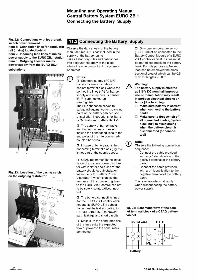
Mounting and Operating ManualCentral Battery System EURO ZB.1
40 CEAG Notlichtsysteme GmbH
Connecting the Battery Supply
Only one temperature sensor (F+ / F-) must be connected to the Battery Control Module of a EURO ZB.1 control cabinet. Its line must be routed separately to the battery bank. For this purpose a 2-wire lead can be employed the cross sectional area of which can be 0.5 mm2 for lengths < 50 m.
Warning!The battery supply is effected at 216 V DC nominal! Improper use or manipulation may result in perilous electrical shocks or burns (due to arcing)! Make sure polarity is correct
when connecting the battery banks.
Make sure to first switch off all connected loads („System blocking“) to avoid arcing when the battery circuit is disconnected (or connec-ted)!
Note:Observe the following connection sequence:– Connect the cable provided
with a „+“ identification to the positive terminal of the battery bank.
– Connect the cable provided with a „-“ identification to the negative terminal of the battery bank.
The reverse order shall apply when disconnecting the battery power supply.
Observe the data sheets of the battery manufacturer CEAG has included in the supply of the battery banks!Take all statutory rules and ordinances into account that apply at the place where the emergency lighting system is operated!
Notes: Standard supply of CEAG battery cabinets includes a cabinet terminal block where the connecting lines (+/–) for battery supply and a temperatur sensor (F+/F–) are hooked up(see Fig. 24).The PE connection serves to safeguard against current-carrying parts of the battery cabinet (see „Installation Instructions for Batte-ry Cabinets and Battery Racks“).
The supply of battery racks and battery cabinets does not include the connecting lines to the end poles of the interconnected/coupled batteries.
In case of battery racks the connecting terminal block (Fig. 24) is not part of the supply scope.
CEAG recommends the instal-lation of a battery power distribu-tor with isolator and fuses for the battery circuit (see „Installation Instructions for Battery Power Distributor“) which enables the terminals of the connecting lines to the EURO ZB.1 control cabinet to be safely isolated/disconnec-ted.
The battery connecting lines (for the EURO ZB.1 control cabi-net and its EURO US.1 substa-tions) must be laid according to DIN VDE 0100 T520 to prevent earth leakage and short circuits!
Make sure the conductor size of the lines suits the expected flow of power to the consumers connected.
Fig. 23: Location of the casing catch on the outgoing distributor
1 2 3
Fig. 22: Connections with load-break switch cover removedItem 1: Connection lines for conductor rail (mains) located behindItem 2: Incoming feed lines of mains power supply to the EURO ZB.1 stationItem 3: Outgoing lines for mains power supply from the EURO US.1
substations
11.3 Connecting the Battery Supply
Fig. 24: Schematic view of the cabi-net terminal block of a CEAG battery cabinet
EURO ZB.1 F + F –
Battery

Mounting and Operating ManualCentral Battery System EURO ZB.1
41 CEAG Notlichtsysteme GmbH
11.4 Connecting the Supply of a EURO ZB.1 Station
11.5 Connecting the Supply of a EURO US.1 Substation
Connecting the Battery Supply
The modules of the EURO ZB.1 control cabinet (and EURO US.1) and the emer-gency lighting system circuits (controlled via the SKU modules) are energized via the battery supply lines. Moreover, the connected battery banks are charged in this way controlled via the charging unit.
Only if the control (at the central battery system EURO ZB.1 and its substations EURO US.1) has been blocked may the battery supply connections be safely switched off by means of the load-break switch (Batt). Only after the mains sup-ply has been switched off are charging booster and all circuits of the SKUs in deenergized state.
Warning!Please note that starting out from the battery bank (battery cabinet / rack) the connecting lines may still be alive!
Notes: Only carry out the connecting work described here. Switching on and testing the power supply systems is described in Chapter 12 „Commissioning and Miscellaneous Work“!
Connections (+ / –) are acces-sible after the movable part of the load-break switch (Batt) has been removed (to be taken off as illustra-ted in Fig. 21).
Connect the lines for battery supply to the EURO ZB.1 control cabinet as follows:
– Make sure the system and inco-ming feeders have been discon-nected and safeguarded (cf. Chapter 12)!
– Connect the positive conductor to the positive terminal of the load-break switch (Fig. 26, Item 3).
– Connect the negative conductor to the negative terminal of the load-break switch (Fig. 26, Item 3).
Substations EURO US.1 are energized via the power supply of the pertinent EURO ZB.1 system (see outgoing distri-butor in Fig. 25, Item 2 and outgoing lines in Fig. 26, Item 5). An outgoing distributor (reference No. 400 71 347 161) can be employed for a battery power supply system. The middle terminal and pertinent fuse remain unused!
Notes: Only carry out the connecting work described here. Switching on and testing the power supply systems is described in Chapter 12 „Commissioning and Miscellaneous Work“!
To facilitate work outgoing distributors may be removed from the conductor rail in forward direction after the catch on the casing bottom has been released.After the outgoing lines have been hooked up the outgoing distribu-tor can be replaced in position on the conductor rail and snapped into place.
Connect the lines for battery power supply to a EURO US.1 substation as follows:– Make sure the system and inco-
ming feeders have been discon-nected and safeguarded (cf. Chapter 12)!
– Lay the incoming lines to/within the EURO ZB.1 control cabinet and in its cable ducts (Fig. 18, Item 3 and Fig. 22, Item 3) and to/within the control cabinet of the EURO US.1 substation.
– Connect the positive conductor to the positive terminal of the out-going distributor (Fig. 26, Item 5).
– Connect the negative conductor to the negative terminal of the out-going distributor (Fig. 26, Item 5).
Note:The battery power supply is hooked up within the control ca-binet of the EURO US.1 substati-ons, as described under Pt. 11.5.
Abb. 25: Location of the load-break switchItem 1: Location of load-break switch for battery supplyItem 2: Outgoing distributors (Batt)Item 3: Cabinet distributor (Batt)
Always observe warning notes!
Fig. 26: Open load-break switch (Batt) with
Item 1: Connecting lines for conductor rails (Batt) located behindItem 2: Fuses (Batt)Item 3: Connections (+ / –) for battery supplyItem 4: Shunt for battery current measurementItem 5: Terminals (+ / –) and outgoing lines for battery supply to EURO US.1 substations
1 2 3 4 5
1 32
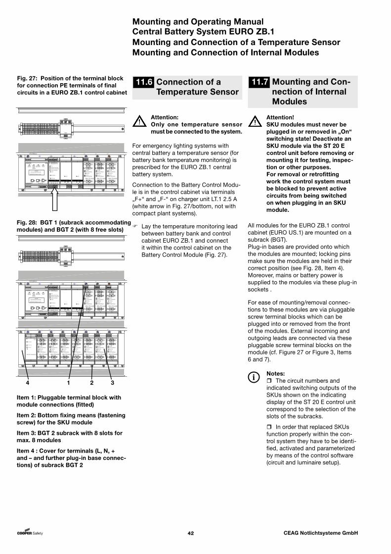
Mounting and Operating ManualCentral Battery System EURO ZB.1
42 CEAG Notlichtsysteme GmbH
11.7 Mounting and Con-nection of Internal Modules
Mounting and Connection of a Temperature SensorMounting and Connection of Internal Modules
All modules for the EURO ZB.1 control cabinet (EURO US.1) are mounted on a subrack (BGT). Plug-in bases are provided onto which the modules are mounted; locking pins make sure the modules are held in their correct position (see Fig. 28, Item 4). Moreover, mains or battery power is supplied to the modules via these plug-in sockets .
For ease of mounting/removal connec-tions to these modules are via pluggable screw terminal blocks which can be plugged into or removed from the front of the modules. External incoming and outgoing leads are connected via these pluggable screw terminal blocks on the module (cf. Figure 27 or Figure 3, Items 6 and 7).
Notes: The circuit numbers and indicated switching outputs of the SKUs shown on the indicating display of the ST 20 E control unit correspond to the selection of the slots of the subracks.
In order that replaced SKUs function properly within the con-trol system they have to be identi-fied, activated and parameterized by means of the control software (circuit and luminaire setup).
Attention:Only one temperature sensor must be connected to the system.
For emergency lighting systems with central battery a temperature sensor (for battery bank temperature monitoring) is prescribed for the EURO ZB.1 central battery system.
Connection to the Battery Control Modu-le is in the control cabinet via terminals „F+“ and „F-“ on charger unit LT.1 2.5 A (white arrow in Fig. 27/bottom, not with compact plant systems).
Lay the temperature monitoring lead between battery bank and control cabinet EURO ZB.1 and connect it within the control cabinet on the Battery Control Module (Fig. 27).
Attention!SKU modules must never be plugged in or removed in „On“ switching state! Deactivate an SKU module via the ST 20 E control unit before removing or mounting it for testing, inspec-tion or other purposes.For removal or retrofitting work the control system must be blocked to prevent active circuits from being switched on when plugging in an SKU module.
Fig. 27: Position of the terminal block for connection PE terminals of final circuits in a EURO ZB.1 control cabinet
11.6 Connection of a Temperature Sensor
Item 1: Pluggable terminal block with module connections (fitted)
Item 2: Bottom fixing means (fastening screw) for the SKU module
Item 3: BGT 2 subrack with 8 slots for max. 8 modules
Item 4 : Cover for terminals (L, N, + and – and further plug-in base connec-tions) of subrack BGT 2
Fig. 28: BGT 1 (subrack accommodating modules) and BGT 2 (with 8 free slots)
ST20 ZB96 kpl
22 32211211 31
Betrieb StorungNetzausfallBatterie-Operation FailureMains Failurebetrieb
BatteryOperation
CEAGSicherheitstechnik
ZB 96 Version 0.21
Menu
AGE
S4 GNDS2S1 S3 UH Drucker/Printer
SKU CG 2x3A
Service
Storung/FailureEin/On
NetzMains5AT
NetzMains5AT
Batt.
5AT+
Batt.
5AT+
Batt.
5AT-
Batt.
5AT-
U101 U202
SKU
1 2
1 2
Storung/FailureEin/On1
2
SKU CG 2x3A
Service
Storung/FailureEin/On
NetzMains5AT
NetzMains5AT
Batt.
5AT+
Batt.
5AT+
Batt.
5AT-
Batt.
5AT-
U101 U202
SKU
1 2
1 2
Storung/FailureEin/On1
2
SKU CG 2x3A
Service
Storung/FailureEin/On
NetzMains5AT
NetzMains5AT
Batt.
5AT+
Batt.
5AT+
Batt.
5AT-
Batt.
5AT-
U101 U202
SKU
1 2
1 2
Storung/FailureEin/On1
2
SKU CG 2x3A
Service
Storung/FailureEin/On
NetzMains5AT
NetzMains5AT
Batt.
5AT+
Batt.
5AT+
Batt.
5AT-
Batt.
5AT-
U101 U202
SKU
1 2
1 2
Storung/FailureEin/On1
2
SKU CG 2x3A
Service
Storung/FailureEin/On
NetzMains5AT
NetzMains5AT
Batt.
5AT+
Batt.
5AT+
Batt.
5AT-
Batt.
5AT-
U101 U202
SKU
1 2
1 2
Storung/FailureEin/On1
2
SKU CG 2x3A
Service
Storung/FailureEin/On
NetzMains5AT
NetzMains5AT
Batt.
5AT+
Batt.
5AT+
Batt.
5AT-
Batt.
5AT-
U101 U202
SKU
1 2
1 2
Storung/FailureEin/On1
2
SKU CG 2x3A
Service
Storung/FailureEin/On
NetzMains5AT
NetzMains5AT
Batt.
5AT+
Batt.
5AT+
Batt.
5AT-
Batt.
5AT-
U101 U202
SKU
1 2
1 2
Storung/FailureEin/On1
2
DC-DC
+-+-21IN 24VDC
OUT
24V extern
24V intern
6V intern
DC-DC Wandler.2
SKU CG 2x3A
Service
Storung/FailureEin/On
NetzMains5AT
NetzMains5AT
Batt.
5AT+
Batt.
5AT+
Batt.
5AT-
Batt.
5AT-
U101 U202
SKU
1 2
1 2
Storung/FailureEin/On1
2
SKU CG 2x3A
Service
Storung/FailureEin/On
NetzMains5AT
NetzMains5AT
Batt.
5AT+
Batt.
5AT+
Batt.
5AT-
Batt.
5AT-
U101 U202
SKU
1 2
1 2
Storung/FailureEin/On1
2
SKU CG 2x3A
Service
Storung/FailureEin/On
NetzMains5AT
NetzMains5AT
Batt.
5AT+
Batt.
5AT+
Batt.
5AT-
Batt.
5AT-
U101 U202
SKU
1 2
1 2
Storung/FailureEin/On1
2
+ -24V In
+ -CCB
+ -I
+ -F
11 12 21 31 32 + -22BST
Ein/OnStarkladung / Boost-ChargeLadestorung / Charge-Failure
ServiceISO-Fehler / ISO-Failure
ISO-Test -
ISO-Test +
BCMBattery Control Module
+ -+ -
CM 1.7A DCCharger Module
Ein/On
CCB
S2S1
+ -+ -
CM 1.7A DCCharger Module
Ein/On
CCB
S2S1
E
E
G G
G
A
A
AE
4 1 2 3

Mounting and Operating ManualCentral Battery System EURO ZB.1
43 CEAG Notlichtsysteme GmbH
11.8 Connection of a DSL Module
Fig. 31: Schematic circuit diagram of a DLS module. All eight inputs can be wired like input 1 (L1, N1).
For each switching command a line must be laid between control cabinet (EURO ZB.1 or EURO US.1) and the distributor for the mains supply (of the circuits monitored).
Figure 31 shows the schematic circuit diagram of a DLS module.
The terminal assignment can be seen in figure 30.
Leads having a conductor size of up to 2.5 mm2 may be connected to the terminals.
Fig. 29: DLS module
Fig. 30: Terminal assignment on DLS module (top/bottom)
Connection of a DLS Module
Emergency lightningGeneral lighting

Mounting and Operating ManualCentral Battery System EURO ZB.1
44 CEAG Notlichtsysteme GmbH
Fig. 33: Schematic circuit diagram of an SDS module. All eight inputs can be wired like input S1 (11, 12).
For each switching command a line must be laid between control cabinet (EURO ZB.1 or EURO US.1) and the distribu-tor for the mainsr supply (of the circuits monitored).
Figure 33 shows the schematic circuit diagram of an SDS module.
The terminal assignment can be seen in figure 32.
Leads having a conductor size of up to 2.5 mm2 may be connected to the terminals.
Fig. 32: SDS module with terminal assignment on module (top/bottom)
Connection of an SDS Module
11.9 Connection of SDS 8 Module
Emergency lightingGeneral lighting
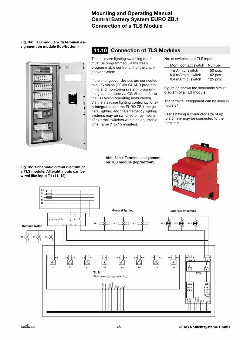
Mounting and Operating ManualCentral Battery System EURO ZB.1
45 CEAG Notlichtsysteme GmbH
Fig. 35: Schematic circuit diagram of a TLS module. All eight inputs can be wired like input T1 (11, 12).
The staircase lighting switching mode must be programmed via the freely programmable control unit of the chan-geover system.
If the changeover devices are connected to a CG Vision (CEWA GUARD program-ming and monitoring system) program-ming can be done via CG Vision (refer to the CG Vision operating instructions).Via the staircase lighting control optional-ly integrated into the EURO ZB.1 the ge-neral lighting and the emergency lighting systems may be switched on by means of external switches within an adjustable time frame (1 to 15 minutes).
Fig. 34: TLS module with terminal as-signment on module (top/bottom)
Connection of a TLS Module
No. of switches per TLS input:
Mom. contact switch Number 1 mA m.c. switch 50 pcs. 0.8 mA m.c. switch 62 pcs. 0.4 mA m.c. switch 125 pcs.
Figure 35 shows the schematic circuit diagram of a TLS module.
The terminal assignment can be seen in figure 34.
Leads having a conductor size of up to 2.5 mm2 may be connected to the terminals.
11.10 Connection of TLS Modules
Abb. 34a : Terminal assignment on TLS module (top/bottom)
Contact switch
Emergency lightingGeneral lighting
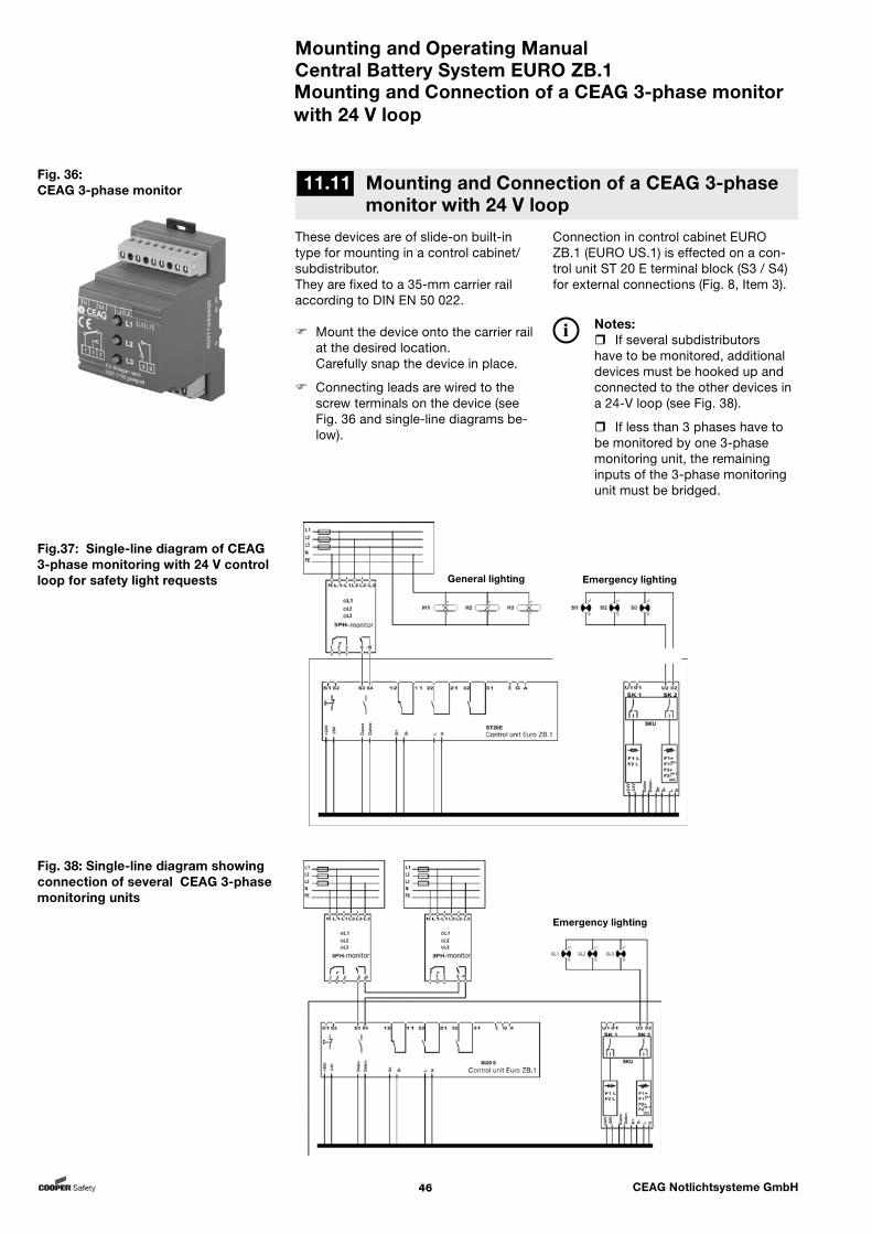
Mounting and Operating ManualCentral Battery System EURO ZB.1
46 CEAG Notlichtsysteme GmbH
Connection in control cabinet EURO ZB.1 (EURO US.1) is effected on a con-trol unit ST 20 E terminal block (S3 / S4) for external connections (Fig. 8, Item 3).
Notes: If several subdistributors have to be monitored, additional devices must be hooked up and connected to the other devices in a 24-V loop (see Fig. 38). If less than 3 phases have to be monitored by one 3-phase monitoring unit, the remaining inputs of the 3-phase monitoring unit must be bridged.
These devices are of slide-on built-in type for mounting in a control cabinet/subdistributor.They are fixed to a 35-mm carrier rail according to DIN EN 50 022.
Mount the device onto the carrier rail at the desired location.
Carefully snap the device in place.
Connecting leads are wired to the screw terminals on the device (see Fig. 36 and single-line diagrams be-low).
Fig. 36: CEAG 3-phase monitor
Mounting and Connection of a CEAG 3-phase monitor with 24 V loop
11.11 Mounting and Connection of a CEAG 3-phase monitor with 24 V loop
Fig. 38: Single-line diagram showing connection of several CEAG 3-phase monitoring units
Fig.37: Single-line diagram of CEAG 3-phase monitoring with 24 V control loop for safety light requests Emergency lightingGeneral lighting
Emergency lighting
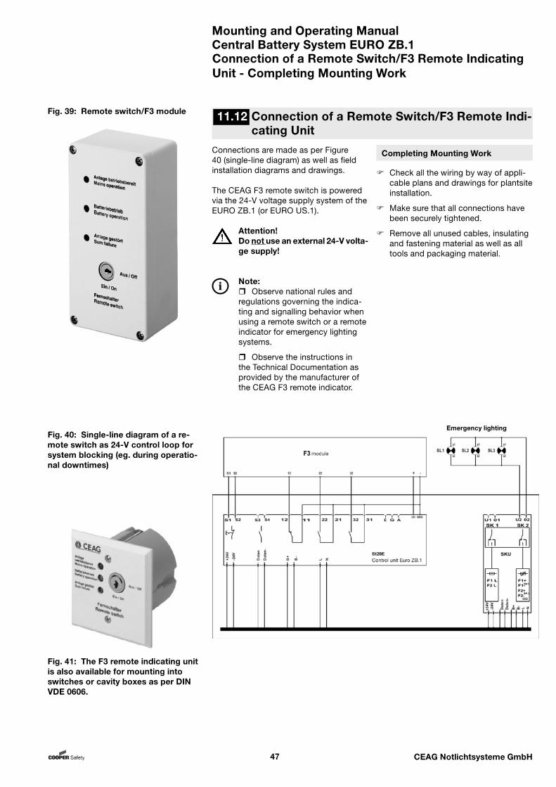
Mounting and Operating ManualCentral Battery System EURO ZB.1
47 CEAG Notlichtsysteme GmbH
Completing Mounting Work
Check all the wiring by way of appli-cable plans and drawings for plantsite installation.
Make sure that all connections have been securely tightened.
Remove all unused cables, insulating and fastening material as well as all tools and packaging material.
Connections are made as per Figure 40 (single-line diagram) as well as field installation diagrams and drawings.
The CEAG F3 remote switch is powered via the 24-V voltage supply system of the EURO ZB.1 (or EURO US.1).
Attention!Do not use an external 24-V volta-ge supply!
Note: Observe national rules and regulations governing the indica-ting and signalling behavior when using a remote switch or a remote indicator for emergency lighting systems.
Observe the instructions in the Technical Documentation as provided by the manufacturer of the CEAG F3 remote indicator.
Fig. 40: Single-line diagram of a re-mote switch as 24-V control loop for system blocking (eg. during operatio-nal downtimes)
Fig. 39: Remote switch/F3 module
Connection of a Remote Switch/F3 Remote Indicating Unit - Completing Mounting Work
Fig. 41: The F3 remote indicating unit is also available for mounting into switches or cavity boxes as per DIN VDE 0606.
11.12 Connection of a Remote Switch/F3 Remote Indi-cating Unit
Emergency lighting

Mounting and Operating ManualCentral Battery System EURO ZB.1
48 CEAG Notlichtsysteme GmbH
Warning! Commissioning or re-
starting (after retrofitting or maintenance/repairs) of the emergency lighting system or the EURO ZB.1 system must only be performed by skilled ectrical personnel having special knowledge of the legal and technical prerequisites governing the set-up and operation of emergency/safety lighing system and the design and control of the equipment dealt with here.
Work on the general supply network and laying of power, signalling and control lines/cabling as well as connec-tion of the battery supply must only be carried out by skilled electrical personnel.
Take all measures required to warrant safety at the workplace! Aside from observing general technical standards and practices this also applies to the instruc-tions given in Chapter 1, Chapters 7 to 9 and what has been specified and laid down in Chapter 10 „Moun-ting“.
Notes: Laying of connecting lines must exclusively be performed in conformity with applicable guide-lines and standards of electrical engineering (eg. DIN VDE 0100 standards series).
In addition please observe all national guidelines and provisions ruling in the country where the plant is erected and operated.
Attention! Never switch the mains
or battery supply on or off under load. In both cases the system must have been blocked first via the ST 20 E control unit (or a remote switch).
The control software and its latest switching state are stored in non-volatile memo-ry.
When working on electrical systems (eg. connecting control or signalling lines) or electronic systems (eg. inserting or withdrawing mo-dules in the control cabinet) the following is to be obser-ved:
– ESD precautionary measures and – the technical documenta- tion for the equipment!
Notes: Performing the work described below requires knowledge of how to operate the EURO ZB.1 system (cf. „14 Controlling a EURO ZB.1 (EURO US.1) Central Battery System“).
Many work items necessi-tate disconnection of the sytem for safety reasons (or to protect modules and components). As the system is reversed to battery supply when the mains is swit-ched off certain work procedures have to be followed as described hereunder.
Commissioning and Further Work
12 Commissioning and Further Work
Mounting and Operating ManualCentral Battery System EURO ZB.1
49 CEAG Notlichtsysteme GmbH
Disconnecting/Switching-on an Emergency Lighting System under Battery Supply
12.1 Disconnecting/Switching-on an Emergency Lighting System
under Battery Supply
Before re-connecting the battery sup-ply at the connections of the battery bank switch on the mains power supply system and make sure that the system is blocked (see 26). Following this, you may switch on the battery supply on the battery bank.
The above instructions apply analogously in case that the mains supply and/or battery supply of a EURO ZB.1 or EURO US.1 control cabinet shall be disconnec-ted or switched on.
Do not switch the mains power supp-ly of a control cabinet (EURO ZB.1 or EURO US.1) off or on under load (ie. with the final circuits being switched on).
Do not switch the battery supply of a control cabinet (EURO ZB.1 or EURO US.1) off or on under load (ie. with the final circuits being switched on).
Before you disconnect or switch on
the mains and/or battery supply make sure that the control system has been blocked (see 12.3).
This is done via the menu item „Block/Enable Unit“ in menu 26 „Blocking, Ack-nowledgment“ of the control software.
Danger!Turning the mains supply on or off within the pertinent distributor should never take place under load (ie. when final circuits are switched on)!
If the power supply to the general lighting system or the mains supply of the emer-gency lighting system fails or is switched off the emergency lighting system control will reverse to battery supply. In this case a voltage of 216 V DC is applied, so take care:
Danger!Never disconnect or connect lines under load to the battery bank (battery cabinet or battery rack)!
The same applies if the load-break switch for battery supply in the control cabinet (EURO ZB.1 / EURO US.1) is opened (or closed) under load!
Before disconnecting the emergency lighting system on the distributor of the general mains supply and/or the connections of the battery bank for battery supply make sure to block the plant as described in Section 12.3.
Following this, first disconnect the battery supply and then disconnect the mains supply.
Take safety measures to ensure that plant remains disconnected as long as you work on the system or until the operationally safe state of the system has been restored.
Attention!In case several systems (EURO ZB.1 with EURO US.1 substati-ons) are supplied with power from a battery bank all systems must first be blocked!Start with disconnecting the lo-west level of the EURO US.1 sub-stations before you disconnect the EURO ZB.1 central battery system!
12.2 Disconnecting/Swit-ching-on a EURO ZB.1 Control Cabinet or EURO US.1
12.3 Block/Release the Control of a EURO ZB.1 Control Cabinet or EURO US.1
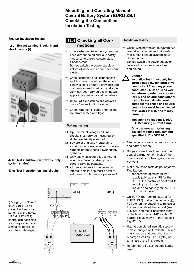
Mounting and Operating ManualCentral Battery System EURO ZB.1
50 CEAG Notlichtsysteme GmbH
Check whether the entire system has been disconnected and take safety measures to ensure system stays disconnected.
Do not switch the power supply on before all work items have been com-pleted.
Check condition of all connections and lines/leads based on the emer-gency lighting system’s drawings and diagrams as well whether installation work has been carried out in line with applicable standards and guidelines.
Check all connections and screwed glands/unions for tight seating.
Check whether all cable entry points are firmly seated and tight.
Voltage testing
Input terminal voltage and final circuits must only be measured by skilled electrical personnel!
Beware of and take measures to avoid danger associated with measu-rements on polyphase power supply systems!
Only use measuring devices having adequate dielectric strength and current carrying capacity.
All measurements to be taken on internal installations must be left to authorized CEAG service personnel!
Insulation testing
Check whether the entire system has been disconnected and take safety measures to ensure system stays disconnected. Do not switch the power supply on before all work items have been completed.
Danger!Insulation tests must only be carried out between protective conductor PE and any phase conductor L1, L2 or L3 as well as between protective conduc-tor PE and neutral conductor N.If circuits contain electronic components phase and neutral conductors must be connected with each other during measu-rements.
Measuring voltage max. 500V DC. Measuring current 1 mA.
Only use measuring/testing devices meeting requirements specified in DIN VDE 0413.
Disconnect connection lines for mains and battery supply.
Bridge connections L and N of the control cabinet on terminals of the mains power supply/outgoing distri-butors 1).
Make insulation tests as per adjacent Fig. 42b on– connections of mains power
supply (L/N) against PE for the EURO ZB.1 control cabinet and its outgoing distributors
– und and analogously on the EURO US.1 substations.
On EURO ZB.1 control cabinet (or EURO US.1) bridge connections U1 / 01 etc. on the outgoing terminals of the final circuits of the cabinet (see Fig. 42a) and make insulation tests of the final circuits U1/01 or U2/02 against PE as shown in the adjacent Fig. 42c. 1)
Having completed insulation testing remove bridges on terminals L/ N (on mains supply and outgoing distri-butors) as well as U1 / 01 (etc.) on terminals of the final circuits.
Re-connect all disconnected leads/lines!
12.4 Checking all Con-nections
1) Bridging L / N and/or U1 / 01 ( ... ) will prevent active com-ponents of the EURO ZB.1 (EURO US.1)control cabinet’s elec-tronic equipment and luminaires (ballasts) from being damaged!
42 b: Test insulation on power supply system (mains)
42 c: Test insulation on final circuits
Fig. 42: Insulation Testing
42 a: Extract terminal block (1) and short circuits (2)
Checking the ConnectionsInsulation Testing
1 2
42 b) 42 c)
EURO ZB.1 (EURO US.1)
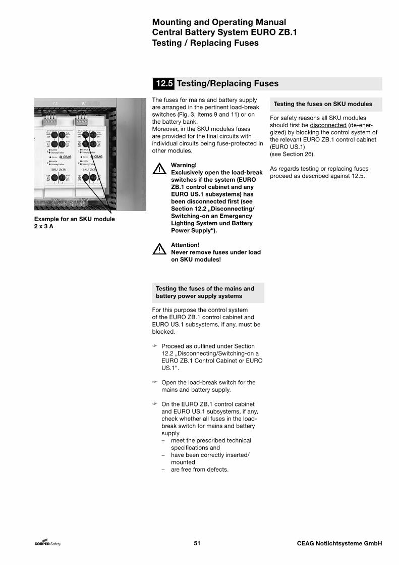
Mounting and Operating ManualCentral Battery System EURO ZB.1
51 CEAG Notlichtsysteme GmbH
The fuses for mains and battery supply are arranged in the pertinent load-break switches (Fig. 3, Items 9 and 11) or on the battery bank.Moreover, in the SKU modules fuses are provided for the final circuits with individual circuits being fuse-protected in other modules.
Warning!Exclusively open the load-break switches if the system (EURO ZB.1 control cabinet and any EURO US.1 subsystems) has been disconnected first (see Section 12.2 „Disconnecting/Switching-on an Emergency Lighting System und Battery Power Supply“).
Attention!Never remove fuses under load on SKU modules!
Testing the fuses of the mains and battery power supply systems
For this purpose the control system of the EURO ZB.1 control cabinet and EURO US.1 subsystems, if any, must be blocked.
Proceed as outlined under Section 12.2 „Disconnecting/Switching-on a EURO ZB.1 Control Cabinet or EURO US.1“.
Open the load-break switch for the mains and battery supply.
On the EURO ZB.1 control cabinet and EURO US.1 subsystems, if any, check whether all fuses in the load-break switch for mains and battery supply– meet the prescribed technical
specifications and– have been correctly inserted/
mounted– are free from defects.
Testing the fuses on SKU modules
For safety reasons all SKU modules should first be disconnected (de-ener-gized) by blocking the control system of the relevant EURO ZB.1 control cabinet (EURO US.1) (see Section 26).
As regards testing or replacing fuses proceed as described against 12.5.
12.5 Testing/Replacing Fuses
Example for an SKU module 2 x 3 A
Testing / Replacing Fuses
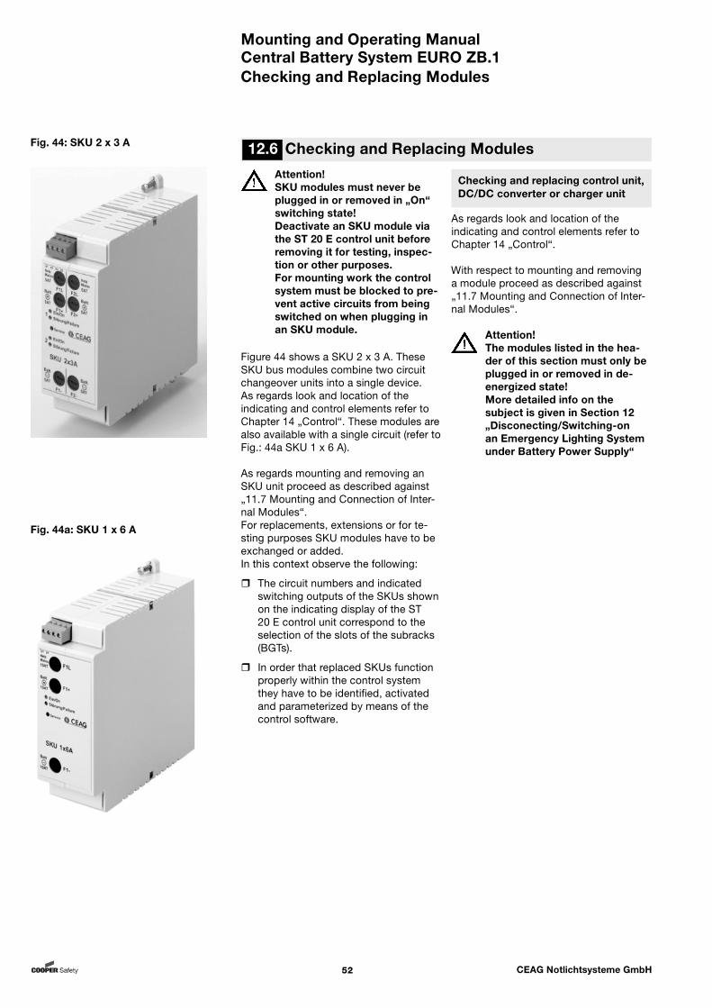
Mounting and Operating ManualCentral Battery System EURO ZB.1
52 CEAG Notlichtsysteme GmbH
Checking and replacing control unit, DC/DC converter or charger unit
As regards look and location of the indicating and control elements refer to Chapter 14 „Control“.
With respect to mounting and removing a module proceed as described against „11.7 Mounting and Connection of Inter-nal Modules“.
Attention!The modules listed in the hea-der of this section must only be plugged in or removed in de-energized state!More detailed info on the subject is given in Section 12 „Disconecting/Switching-on an Emergency Lighting System under Battery Power Supply“
12.6 Checking and Replacing ModulesFig. 44: SKU 2 x 3 A
Attention!SKU modules must never be plugged in or removed in „On“ switching state! Deactivate an SKU module via the ST 20 E control unit before removing it for testing, inspec-tion or other purposes.For mounting work the control system must be blocked to pre-vent active circuits from being switched on when plugging in an SKU module.
Figure 44 shows a SKU 2 x 3 A. These SKU bus modules combine two circuit changeover units into a single device. As regards look and location of the indicating and control elements refer to Chapter 14 „Control“. These modules are also available with a single circuit (refer to Fig.: 44a SKU 1 x 6 A).
As regards mounting and removing an SKU unit proceed as described against „11.7 Mounting and Connection of Inter-nal Modules“.For replacements, extensions or for te-sting purposes SKU modules have to be exchanged or added. In this context observe the following:
The circuit numbers and indicated switching outputs of the SKUs shown on the indicating display of the ST 20 E control unit correspond to the selection of the slots of the subracks (BGTs).
In order that replaced SKUs function properly within the control system they have to be identified, activated and parameterized by means of the control software.
Checking and Replacing Modules
Fig. 44a: SKU 1 x 6 A

Mounting and Operating ManualCentral Battery System EURO ZB.1
53 CEAG Notlichtsysteme GmbH
13 Switching the System ON
Note:For the sequence of actions listed below it has been assumed that the system (EURO ZB.1 including EURO US.1 substations) has first been blocked and disconnected from the power.It has further been assumed that the control software parameters previously set as well as the rele-vant switching states have not be changed in the meantime! In case of doubt observe the de-tailed description given in Section 12 „Disconnecting / Switching-on an Emergency Lighting System under Battery Supply“.
Switch on the mains supply of the EURO ZB.1 control cabinet and its EURO US.1 substations via the load-break switches.
Make sure the control system of the EURO ZB.1 control cabinet and its subsystems (EURO US.1), if any, has been blocked. This is done via the menu item „Block/enable Unit“ in menu 25 „Blocking, Acknowledgment“ of the control software.
Take precautionary measures to secu-re this system state against unautho-rized changes!
Switch on the battery supply of the EURO ZB.1 control cabinet and its EURO US.1 substations via the load-break switches.
Operate the controls via menu item „Enable unit“.
Item 1: Upper terminal block for the (monitoring) inputsItem 2: Lower terminal blockItem 3: Indicating LEDs LEDs 1 ... 8 light up if the circuit has been closedLED „Störung/Failure“ lights up if mo-dule malfunction has been detectedItem 4: Fixing element (fastening screw) for the SKU module
Fig. 45: TLS module
Item 1: Upper terminal blockItem 2: Lower terminal blockItem 3: Indicating LED - LED „Störung/Failure“ lights up if mo-dule malfunction has been detectedItem 4: Fixing element (fastening screw) for the SKU module
Switching the System ON
1 2 3 4
Fig. 46: Control and indicating ele-ments on DLS/3Ph bus modules
1 2 3 4
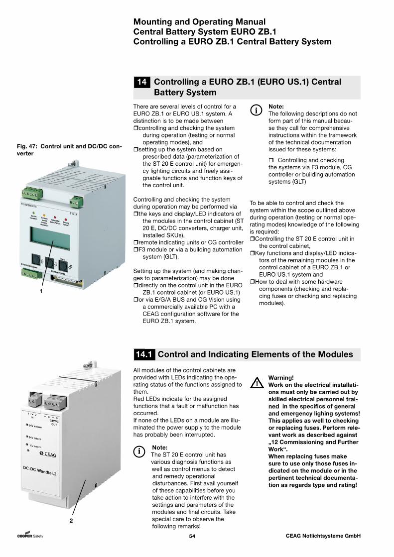
Mounting and Operating ManualCentral Battery System EURO ZB.1
54 CEAG Notlichtsysteme GmbH
Fig. 47: Control unit and DC/DC con-verter
1
2
9 14.1 Control and Indicating Elements of the Modules
All modules of the control cabinets are provided with LEDs indicating the ope-rating status of the functions assigned to them. Red LEDs indicate for the assigned functions that a fault or malfunction has occurred.If none of the LEDs on a module are illu-minated the power supply to the module has probably been interrupted.
Note: The ST 20 E control unit has various diagnosis functions as well as control menus to detect and remedy operational disturbances. First avail yourself of these capabilities before you take action to interfere with the settings and parameters of the modules and final circuits. Take special care to observe the following remarks!
14 Controlling a EURO ZB.1 (EURO US.1) Central Battery System
Controlling a EURO ZB.1 Central Battery System
There are several levels of control for a EURO ZB.1 or EURO US.1 system. A distinction is to be made betweencontrolling and checking the system
during operation (testing or normal operating modes), and
setting up the system based on prescribed data (parameterization of the ST 20 E control unit) for emergen-cy lighting circuits and freely assi-gnable functions and function keys of the control unit.
Controlling and checking the system during operation may be performed viathe keys and display/LED indicators of
the modules in the control cabinet (ST 20 E, DC/DC converters, charger unit, installed SKUs),
remote indicating units or CG controller F3 module or via a building automation
system (GLT).
Setting up the system (and making chan-ges to parameterization) may be donedirectly on the control unit in the EURO
ZB.1 control cabinet (or EURO US.1) or via E/G/A BUS and CG Vision using
a commercially available PC with a CEAG configuration software for the EURO ZB.1 system.
Note:The following descriptions do not form part of this manual becau-se they call for comprehensive instructions within the framework of the technical documentation issued for these systems:
Controlling and checking the systems via F3 module, CG controller or building automation systems (GLT)
To be able to control and check the system within the scope outlined above during operation (testing or normal ope-rating modes) knowledge of the following is required:Controlling the ST 20 E control unit in
the control cabinet,Key functions and display/LED indica-
tors of the remaining modules in the control cabinet of a EURO ZB.1 or EURO US.1 system and
How to deal with some hardware components (checking and repla-cing fuses or checking and replacing modules).
Warning!Work on the electrical installati-ons must only be carried out by skilled electrical personnel trai-ned in the specifics of general and emergency lighing systems! This applies as well to checking or replacing fuses. Perform rele-vant work as described against „12 Commissioning and Further Work“.When replacing fuses make sure to use only those fuses in-dicated on the module or in the pertinent technical documenta-tion as regards type and rating!
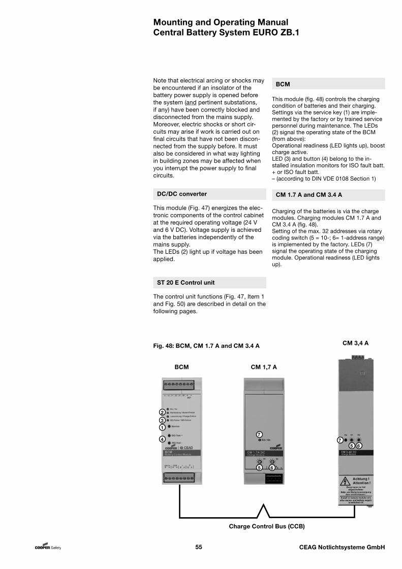
Mounting and Operating ManualCentral Battery System EURO ZB.1
55 CEAG Notlichtsysteme GmbH
DC/DC converter
This module (Fig. 47) energizes the elec-tronic components of the control cabinet at the required operating voltage (24 V and 6 V DC). Voltage supply is achieved via the batteries independently of the mains supply.The LEDs (2) light up if voltage has been applied.
Note that electrical arcing or shocks may be encountered if an insolator of the battery power supply is opened before the system (and pertinent substations, if any) have been correctly blocked and disconnected from the mains supply. Moreover, electric shocks or short cir-cuits may arise if work is carried out on final circuits that have not been discon-nected from the supply before. It must also be considered in what way lighting in building zones may be affected when you interrupt the power supply to final circuits.
ST 20 E Control unit
The control unit functions (Fig. 47, Item 1 and Fig. 50) are described in detail on the following pages.
Fig. 48: BCM, CM 1.7 A and CM 3.4 A
1
2
3
47
5
5
6
67
BCM
Charge Control Bus (CCB)
CM 1,7 A
CM 3,4 A
BCM
This module (fig. 48) controls the charging condition of batteries and their charging. Settings via the service key (1) are imple-mented by the factory or by trained service personnel during maintenance. The LEDs (2) signal the operating state of the BCM (from above):Operational readiness (LED lights up), boost charge active.LED (3) and button (4) belong to the in-stalled insulation monitors for ISO fault batt. + or ISO fault batt.– (according to DIN VDE 0108 Section 1)
CM 1.7 A and CM 3.4 A
Charging of the batteries is via the charge modules. Charging modules CM 1.7 A and CM 3.4 A (fig. 48).Setting of the max. 32 addresses via rotary coding switch (5 = 10-; 6= 1-address range) is implemented by the factory. LEDs (7) signal the operating state of the charging module. Operational readiness (LED lights up).
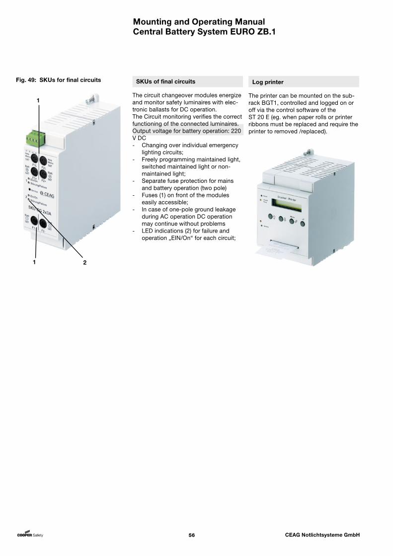
Mounting and Operating ManualCentral Battery System EURO ZB.1
56 CEAG Notlichtsysteme GmbH
SKUs of final circuits
The circuit changeover modules energize and monitor safety luminaires with elec-tronic ballasts for DC operation. The Circuit monitoring verifies the correct functioning of the connected luminaires. Output voltage for battery operation: 220 V DC- Changing over individual emergency
lighting circuits;- Freely programming maintained light,
switched maintained light or non-maintained light;
- Separate fuse protection for mains and battery operation (two pole)
- Fuses (1) on front of the modules easily accessible;
- In case of one-pole ground leakage during AC operation DC operation may continue without problems
- LED indications (2) for failure and operation „EIN/On“ for each circuit;
Log printer
The printer can be mounted on the sub-rack BGT1, controlled and logged on or off via the control software of the ST 20 E (eg. when paper rolls or printer ribbons must be replaced and require the printer to removed /replaced).
Fig. 49: SKUs for final circuits
1
1 2
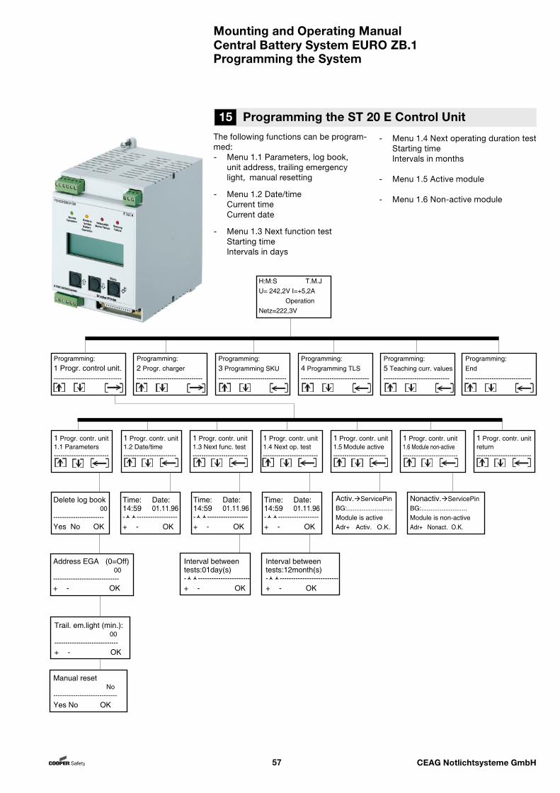
Mounting and Operating ManualCentral Battery System EURO ZB.1
57 CEAG Notlichtsysteme GmbH
The following functions can be program-med:- Menu 1.1 Parameters, log book, unit address, trailing emergency light, manual resetting
- Menu 1.2 Date/time Current time Current date
- Menu 1.3 Next function test Starting time Intervals in days
- Menu 1.4 Next operating duration test Starting time Intervals in months
- Menu 1.5 Active module
- Menu 1.6 Non-active module
15 Programming the ST 20 E Control Unit
Programming the System
H:M:S T.M.JU= 242,2V I=+5,2A OperationNetz=222,3V
Programming:End------------------------------
Programming:1 Progr. control unit.-------------------------------
Programming:2 Progr. charger------------------------------
Programming:3 Programming SKU-------------------------------
Programming:4 Programming TLS-------------------------------
Programming:5 Teaching curr. values------------------------------
Address EGA (0=Off) 00------------------------------+ - OK
Trail. em.light (min.): 00-----------------------------+ - OK
Manual reset No-----------------------------Yes No OK
1 Progr. contr. unit1.1 Parameters-------------------------
Delete log book 00-----------------------Yes No OK
1 Progr. contr. unitreturn-------------------------
1 Progr. contr. unit1.2 Date/time------------------------
1 Progr. contr. unit1.3 Next func. test-------------------------
1 Progr. contr. unit1.4 Next op. test-------------------------
1 Progr. contr. unit1.5 Module active------------------------
1 Progr. contr. unit1.6 Module non-active-------------------------
Time: Date:14:59 01.11.96-------------------+ - OK
Activ.ServicePinBG:.........................Module is activeAdr+ Activ. O.K.
Nonactiv.ServicePinBG:.........................Module is non-activeAdr+ Nonact. O.K.
Time: Date:14:59 01.11.96-------------------+ - OK
Interval between tests:01day(s)------------------------+ - OK
Time: Date:14:59 01.11.96-------------------+ - OK
Interval between tests:12month(s)---------------------------+ - OK
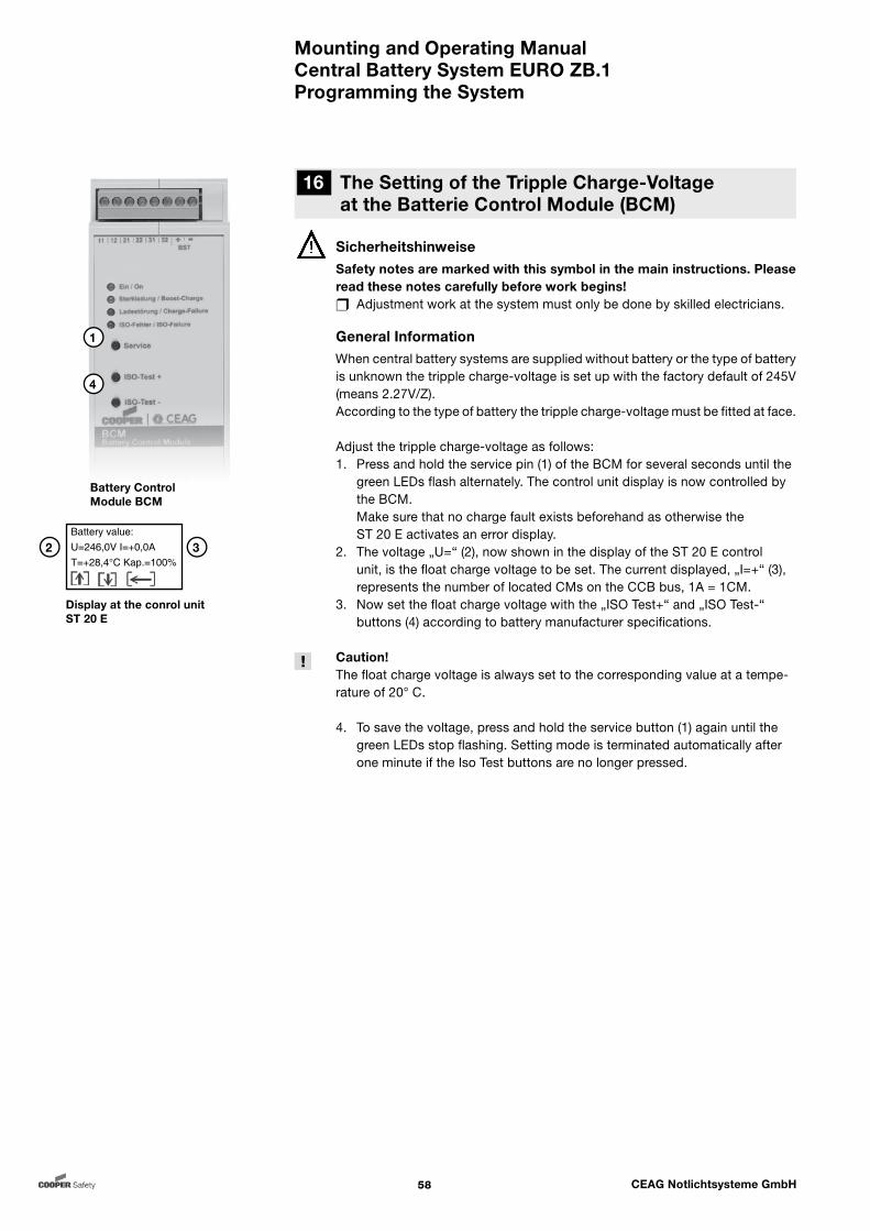
Mounting and Operating ManualCentral Battery System EURO ZB.1
58 CEAG Notlichtsysteme GmbH
16 The Setting of the Tripple Charge-Voltage at the Batterie Control Module (BCM)
Programming the System
1
4
Battery Control Module BCM
SicherheitshinweiseSafety notes are marked with this symbol in the main instructions. Please read these notes carefully before work begins! Adjustment work at the system must only be done by skilled electricians.
General InformationWhen central battery systems are supplied without battery or the type of battery is unknown the tripple charge-voltage is set up with the factory default of 245V (means 2.27V/Z).According to the type of battery the tripple charge-voltage must be fitted at face.
Adjust the tripple charge-voltage as follows:1. Press and hold the service pin (1) of the BCM for several seconds until the green LEDs flash alternately. The control unit display is now controlled by the BCM. Make sure that no charge fault exists beforehand as otherwise the ST 20 E activates an error display. 2. The voltage „U=“ (2), now shown in the display of the ST 20 E control unit, is the float charge voltage to be set. The current displayed, „I=+“ (3), represents the number of located CMs on the CCB bus, 1A = 1CM.3. Now set the float charge voltage with the „ISO Test+“ and „ISO Test-“ buttons (4) according to battery manufacturer specifications.
Caution!The float charge voltage is always set to the corresponding value at a tempe-rature of 20° C.
4. To save the voltage, press and hold the service button (1) again until the green LEDs stop flashing. Setting mode is terminated automatically after one minute if the Iso Test buttons are no longer pressed.
Display at the conrol unit ST 20 E
2 3Battery value:U=246,0V I=+0,0AT=+28,4°C Kap.=100%
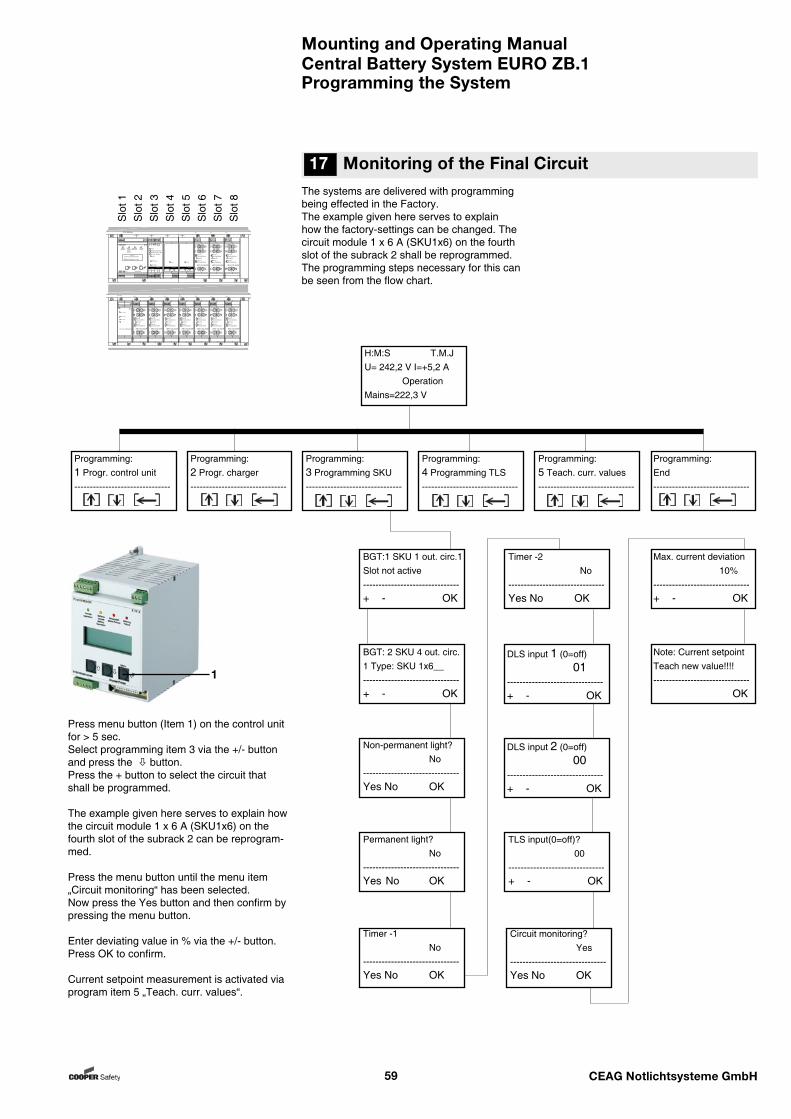
Mounting and Operating ManualCentral Battery System EURO ZB.1
59 CEAG Notlichtsysteme GmbH
17 Monitoring of the Final CircuitThe systems are delivered with programming being effected in the Factory. The example given here serves to explain how the factory-settings can be changed. The circuit module 1 x 6 A (SKU1x6) on the fourth slot of the subrack 2 shall be reprogrammed. The programming steps necessary for this can be seen from the flow chart.
Press menu button (Item 1) on the control unit for > 5 sec.Select programming item 3 via the +/- button and press the button. Press the + button to select the circuit that shall be programmed.
The example given here serves to explain how the circuit module 1 x 6 A (SKU1x6) on the fourth slot of the subrack 2 can be reprogram-med.
Press the menu button until the menu item „Circuit monitoring“ has been selected. Now press the Yes button and then confirm by pressing the menu button.
Enter deviating value in % via the +/- button.Press OK to confirm.
Current setpoint measurement is activated via program item 5 „Teach. curr. values“.
S
lot 1
Slo
t 2S
lot 3
Slo
t 4S
lot 5
Slo
t 6S
lot 7
Slo
t 8
Programming the System
1
BGT:1 SKU 1 out. circ.1Slot not active-------------------------------+ - OK
BGT: 2 SKU 4 out. circ. 1 Type: SKU 1x6__-------------------------------+ - OK
Non-permanent light? No-------------------------------Yes No OK
TLS input(0=off)? 00-------------------------------+ - OK
Max. current deviation 10%-------------------------------+ - OK
Note: Current setpointTeach new value!!!!------------------------------- OK
H:M:S T.M.JU= 242,2 V I=+5,2 A OperationMains=222,3 V
Programming:1 Progr. control unit-------------------------------
Programming:2 Progr. charger-------------------------------
Programming:3 Programming SKU-------------------------------
Programming:4 Programming TLS-------------------------------
Programming:End-------------------------------
Programming:5 Teach. curr. values-------------------------------
Permanent light? No-------------------------------Yes No OK
Timer -1 No-------------------------------Yes No OK
Timer -2 No-------------------------------Yes No OK
DLS input 2 (0=off) 00-------------------------------+ - OK
DLS input 1 (0=off) 01-------------------------------+ - OK
Circuit monitoring? Yes-------------------------------Yes No OK
16 The Setting of the Tripple Charge-Voltage at the Batterie Control Module (BCM)
ST20 ZB96 kpl
22 32211211 31
Betrieb StorungNetzausfallBatterie-Operation FailureMains Failurebetrieb
BatteryOperation
CEAGSicherheitstechnik
ZB 96 Version 0.21
Menu
AGE
S4 GNDS2S1 S3 UH Drucker/Printer
SKU CG 2x3A
Service
Storung/FailureEin/On
NetzMains5AT
NetzMains5AT
Batt.
5AT+
Batt.
5AT+
Batt.
5AT-
Batt.
5AT-
U101 U202
SKU
1 2
1 2
Storung/FailureEin/On1
2
SKU CG 2x3A
Service
Storung/FailureEin/On
NetzMains5AT
NetzMains5AT
Batt.
5AT+
Batt.
5AT+
Batt.
5AT-
Batt.
5AT-
U101 U202
SKU
1 2
1 2
Storung/FailureEin/On1
2
SKU CG 2x3A
Service
Storung/FailureEin/On
NetzMains5AT
NetzMains5AT
Batt.
5AT+
Batt.
5AT+
Batt.
5AT-
Batt.
5AT-
U101 U202
SKU
1 2
1 2
Storung/FailureEin/On1
2
SKU CG 2x3A
Service
Storung/FailureEin/On
NetzMains5AT
NetzMains5AT
Batt.
5AT+
Batt.
5AT+
Batt.
5AT-
Batt.
5AT-
U101 U202
SKU
1 2
1 2
Storung/FailureEin/On1
2
SKU CG 2x3A
Service
Storung/FailureEin/On
NetzMains5AT
NetzMains5AT
Batt.
5AT+
Batt.
5AT+
Batt.
5AT-
Batt.
5AT-
U101 U202
SKU
1 2
1 2
Storung/FailureEin/On1
2
SKU CG 2x3A
Service
Storung/FailureEin/On
NetzMains5AT
NetzMains5AT
Batt.
5AT+
Batt.
5AT+
Batt.
5AT-
Batt.
5AT-
U101 U202
SKU
1 2
1 2
Storung/FailureEin/On1
2
SKU CG 2x3A
Service
Storung/FailureEin/On
NetzMains5AT
NetzMains5AT
Batt.
5AT+
Batt.
5AT+
Batt.
5AT-
Batt.
5AT-
U101 U202
SKU
1 2
1 2
Storung/FailureEin/On1
2
DC-DC
+-+-21IN 24VDC
OUT
24V extern
24V intern
6V intern
DC-DC Wandler.2
SKU CG 2x3A
Service
Storung/FailureEin/On
NetzMains5AT
NetzMains5AT
Batt.
5AT+
Batt.
5AT+
Batt.
5AT-
Batt.
5AT-
U101 U202
SKU
1 2
1 2
Storung/FailureEin/On1
2
SKU CG 2x3A
Service
Storung/FailureEin/On
NetzMains5AT
NetzMains5AT
Batt.
5AT+
Batt.
5AT+
Batt.
5AT-
Batt.
5AT-
U101 U202
SKU
1 2
1 2
Storung/FailureEin/On1
2
SKU CG 2x3A
Service
Storung/FailureEin/On
NetzMains5AT
NetzMains5AT
Batt.
5AT+
Batt.
5AT+
Batt.
5AT-
Batt.
5AT-
U101 U202
SKU
1 2
1 2
Storung/FailureEin/On1
2
+ -24V In
+ -CCB
+ -I
+ -F
11 12 21 31 32 + -22BST
Ein/OnStarkladung / Boost-ChargeLadestorung / Charge-Failure
ServiceISO-Fehler / ISO-Failure
ISO-Test -
ISO-Test +
BCMBattery Control Module
+ -+ -
CM 1.7A DCCharger Module
Ein/On
CCB
S2S1
+ -+ -
CM 1.7A DCCharger Module
Ein/On
CCB
S2S1
E
E
G G
G
A
A
AE
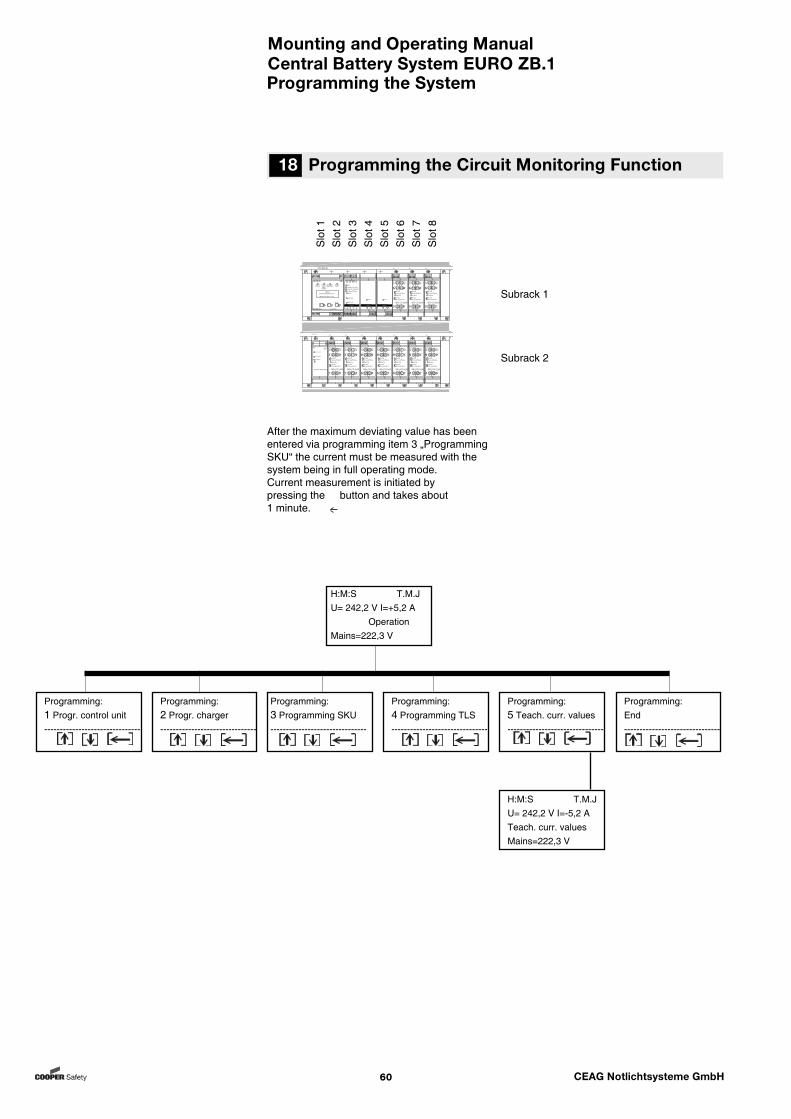
Mounting and Operating ManualCentral Battery System EURO ZB.1
60 CEAG Notlichtsysteme GmbH
After the maximum deviating value has been entered via programming item 3 „Programming SKU“ the current must be measured with the system being in full operating mode.Current measurement is initiated by pressing the button and takes about 1 minute.
Subrack 1
Subrack 2
Slo
t 1S
lot 2
Slo
t 3S
lot 4
Slo
t 5S
lot 6
Slo
t 7S
lot 8
18 Programming the Circuit Monitoring Function
Programming the System
Programming:3 Programming SKU-------------------------------
H:M:S T.M.JU= 242,2 V I=+5,2 A OperationMains=222,3 V
Programming:1 Progr. control unit-------------------------------
Programming:2 Progr. charger-------------------------------
Programming:4 Programming TLS-------------------------------
Programming:5 Teach. curr. values-------------------------------
H:M:S T.M.JU= 242,2 V I=-5,2 ATeach. curr. valuesMains=222,3 V
Programming:End-------------------------------
ST20 ZB96 kpl
22 32211211 31
Betrieb StorungNetzausfallBatterie-Operation FailureMains Failurebetrieb
BatteryOperation
CEAGSicherheitstechnik
ZB 96 Version 0.21
Menu
AGE
S4 GNDS2S1 S3 UH Drucker/Printer
SKU CG 2x3A
Service
Storung/FailureEin/On
NetzMains5AT
NetzMains5AT
Batt.
5AT+
Batt.
5AT+
Batt.
5AT-
Batt.
5AT-
U101 U202
SKU
1 2
1 2
Storung/FailureEin/On1
2
SKU CG 2x3A
Service
Storung/FailureEin/On
NetzMains5AT
NetzMains5AT
Batt.
5AT+
Batt.
5AT+
Batt.
5AT-
Batt.
5AT-
U101 U202
SKU
1 2
1 2
Storung/FailureEin/On1
2
SKU CG 2x3A
Service
Storung/FailureEin/On
NetzMains5AT
NetzMains5AT
Batt.
5AT+
Batt.
5AT+
Batt.
5AT-
Batt.
5AT-
U101 U202
SKU
1 2
1 2
Storung/FailureEin/On1
2
SKU CG 2x3A
Service
Storung/FailureEin/On
NetzMains5AT
NetzMains5AT
Batt.
5AT+
Batt.
5AT+
Batt.
5AT-
Batt.
5AT-
U101 U202
SKU
1 2
1 2
Storung/FailureEin/On1
2
SKU CG 2x3A
Service
Storung/FailureEin/On
NetzMains5AT
NetzMains5AT
Batt.
5AT+
Batt.
5AT+
Batt.
5AT-
Batt.
5AT-
U101 U202
SKU
1 2
1 2
Storung/FailureEin/On1
2
SKU CG 2x3A
Service
Storung/FailureEin/On
NetzMains5AT
NetzMains5AT
Batt.
5AT+
Batt.
5AT+
Batt.
5AT-
Batt.
5AT-
U101 U202
SKU
1 2
1 2
Storung/FailureEin/On1
2
SKU CG 2x3A
Service
Storung/FailureEin/On
NetzMains5AT
NetzMains5AT
Batt.
5AT+
Batt.
5AT+
Batt.
5AT-
Batt.
5AT-
U101 U202
SKU
1 2
1 2
Storung/FailureEin/On1
2
DC-DC
+-+-21IN 24VDC
OUT
24V extern
24V intern
6V intern
DC-DC Wandler.2
SKU CG 2x3A
Service
Storung/FailureEin/On
NetzMains5AT
NetzMains5AT
Batt.
5AT+
Batt.
5AT+
Batt.
5AT-
Batt.
5AT-
U101 U202
SKU
1 2
1 2
Storung/FailureEin/On1
2
SKU CG 2x3A
Service
Storung/FailureEin/On
NetzMains5AT
NetzMains5AT
Batt.
5AT+
Batt.
5AT+
Batt.
5AT-
Batt.
5AT-
U101 U202
SKU
1 2
1 2
Storung/FailureEin/On1
2
SKU CG 2x3A
Service
Storung/FailureEin/On
NetzMains5AT
NetzMains5AT
Batt.
5AT+
Batt.
5AT+
Batt.
5AT-
Batt.
5AT-
U101 U202
SKU
1 2
1 2
Storung/FailureEin/On1
2
+ -24V In
+ -CCB
+ -I
+ -F
11 12 21 31 32 + -22BST
Ein/OnStarkladung / Boost-ChargeLadestorung / Charge-Failure
ServiceISO-Fehler / ISO-Failure
ISO-Test -
ISO-Test +
BCMBattery Control Module
+ -+ -
CM 1.7A DCCharger Module
Ein/On
CCB
S2S1
+ -+ -
CM 1.7A DCCharger Module
Ein/On
CCB
S2S1
E
E
G G
G
A
A
AE
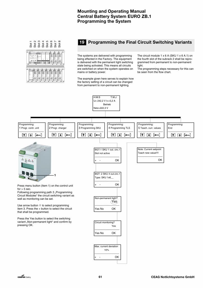
Mounting and Operating ManualCentral Battery System EURO ZB.1
61 CEAG Notlichtsysteme GmbH
The systems are delivered with programming being effected in the Factory. The equipment is delivered with the permanent light switching state being activated. This means all circuits are switched on when the system operates on mains or battery power.
The example given here serves to explain how the factory setting of a circuit can be changed from permanent to non-permanent lighting.
Press menu button (Item 1) on the control unit for > 5 sec. Following programming path 3 „Programming Circuit Modules“ the circuit switching variant as well as monitoring can be set.
Use arrow button to select programming item 3. Press the + button to select the circuit that shall be programmed.
Press the Yes button to select the switching variant „Non-permanent light“ and confirm by pressing OK.
The circuit module 1 x 6 A (SKU 1 x 6 A.1) on the fourth slot of the subrack 2 shall be repro-grammed from permanent to non-permanent light.The programming steps necessary for this can be seen from the flow chart.
19 Programming the Final Circuit Switching Variants
Programming the System
Slo
t 1S
lot 2
Slo
t 3S
lot 4
Slo
t 5S
lot 6
Slo
t 7S
lot 8
1
H:M:S T.M.JU= 242,2 V I=+5,2 A BetriebNetz=222,3 V
Programming:1 Progr. contr. unit-------------------------------
Programming:2 Progr. charger-------------------------------
Programming:4 Programming TLS-------------------------------
Programming:5 Teach. curr. values-------------------------------
Programming:End-------------------------------
Programming:3 Programming SKU-------------------------------
Non-permanent light? Yes-------------------------------Yes No OK
Circuit monitoring? Yes-------------------------------Yes No OK
BGT:1 SKU 1 out. circ.1Slot not active-------------------------------+ - OK
BGT: 2 SKU 4 out.circ.1Type: SKU 1x6__-------------------------------+ - OK
Max. current deviation 10%-------------------------------+ - OK
Note: Current setpointTeach new value!!!!------------------------------- OK
ST20 ZB96 kpl
22 32211211 31
Betrieb StorungNetzausfallBatterie-Operation FailureMains Failurebetrieb
BatteryOperation
CEAGSicherheitstechnik
ZB 96 Version 0.21
Menu
AGE
S4 GNDS2S1 S3 UH Drucker/Printer
SKU CG 2x3A
Service
Storung/FailureEin/On
NetzMains5AT
NetzMains5AT
Batt.
5AT+
Batt.
5AT+
Batt.
5AT-
Batt.
5AT-
U101 U202
SKU
1 2
1 2
Storung/FailureEin/On1
2
SKU CG 2x3A
Service
Storung/FailureEin/On
NetzMains5AT
NetzMains5AT
Batt.
5AT+
Batt.
5AT+
Batt.
5AT-
Batt.
5AT-
U101 U202
SKU
1 2
1 2
Storung/FailureEin/On1
2
SKU CG 2x3A
Service
Storung/FailureEin/On
NetzMains5AT
NetzMains5AT
Batt.
5AT+
Batt.
5AT+
Batt.
5AT-
Batt.
5AT-
U101 U202
SKU
1 2
1 2
Storung/FailureEin/On1
2
SKU CG 2x3A
Service
Storung/FailureEin/On
NetzMains5AT
NetzMains5AT
Batt.
5AT+
Batt.
5AT+
Batt.
5AT-
Batt.
5AT-
U101 U202
SKU
1 2
1 2
Storung/FailureEin/On1
2
SKU CG 2x3A
Service
Storung/FailureEin/On
NetzMains5AT
NetzMains5AT
Batt.
5AT+
Batt.
5AT+
Batt.
5AT-
Batt.
5AT-
U101 U202
SKU
1 2
1 2
Storung/FailureEin/On1
2
SKU CG 2x3A
Service
Storung/FailureEin/On
NetzMains5AT
NetzMains5AT
Batt.
5AT+
Batt.
5AT+
Batt.
5AT-
Batt.
5AT-
U101 U202
SKU
1 2
1 2
Storung/FailureEin/On1
2
SKU CG 2x3A
Service
Storung/FailureEin/On
NetzMains5AT
NetzMains5AT
Batt.
5AT+
Batt.
5AT+
Batt.
5AT-
Batt.
5AT-
U101 U202
SKU
1 2
1 2
Storung/FailureEin/On1
2
DC-DC
+-+-21IN 24VDC
OUT
24V extern
24V intern
6V intern
DC-DC Wandler.2
SKU CG 2x3A
Service
Storung/FailureEin/On
NetzMains5AT
NetzMains5AT
Batt.
5AT+
Batt.
5AT+
Batt.
5AT-
Batt.
5AT-
U101 U202
SKU
1 2
1 2
Storung/FailureEin/On1
2
SKU CG 2x3A
Service
Storung/FailureEin/On
NetzMains5AT
NetzMains5AT
Batt.
5AT+
Batt.
5AT+
Batt.
5AT-
Batt.
5AT-
U101 U202
SKU
1 2
1 2
Storung/FailureEin/On1
2
SKU CG 2x3A
Service
Storung/FailureEin/On
NetzMains5AT
NetzMains5AT
Batt.
5AT+
Batt.
5AT+
Batt.
5AT-
Batt.
5AT-
U101 U202
SKU
1 2
1 2
Storung/FailureEin/On1
2
+ -24V In
+ -CCB
+ -I
+ -F
11 12 21 31 32 + -22BST
Ein/OnStarkladung / Boost-ChargeLadestorung / Charge-Failure
ServiceISO-Fehler / ISO-Failure
ISO-Test -
ISO-Test +
BCMBattery Control Module
+ -+ -
CM 1.7A DCCharger Module
Ein/On
CCB
S2S1
+ -+ -
CM 1.7A DCCharger Module
Ein/On
CCB
S2S1
E
E
G G
G
A
A
AE
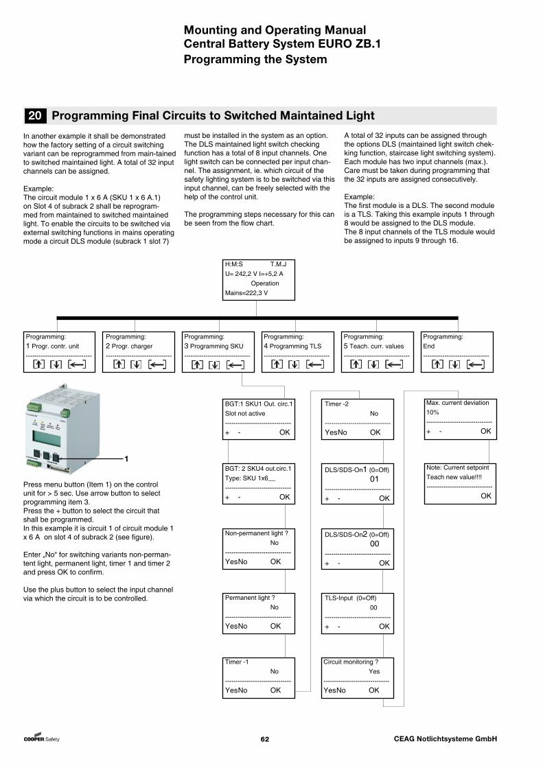
Mounting and Operating ManualCentral Battery System EURO ZB.1
62 CEAG Notlichtsysteme GmbH
A total of 32 inputs can be assigned through the options DLS (maintained light switch chek-king function, staircase light switching system). Each module has two input channels (max.).Care must be taken during programming that the 32 inputs are assigned consecutively.
Example:The first module is a DLS. The second module is a TLS. Taking this example inputs 1 through 8 would be assigned to the DLS module. The 8 input channels of the TLS module would be assigned to inputs 9 through 16.
Press menu button (Item 1) on the control unit for > 5 sec. Use arrow button to select programming item 3. Press the + button to select the circuit that shall be programmed.In this example it is circuit 1 of circuit module 1 x 6 A on slot 4 of subrack 2 (see figure).
Enter „No“ for switching variants non-perman-tent light, permanent light, timer 1 and timer 2 and press OK to confirm.
Use the plus button to select the input channel via which the circuit is to be controlled.
20 Programming Final Circuits to Switched Maintained Light
Programming the System
In another example it shall be demonstrated how the factory setting of a circuit switching variant can be reprogrammed from main-tained to switched maintained light. A total of 32 input channels can be assigned.
Example: The circuit module 1 x 6 A (SKU 1 x 6 A.1) on Slot 4 of subrack 2 shall be reprogram-med from maintained to switched maintained light. To enable the circuits to be switched via external switching functions in mains operating mode a circuit DLS module (subrack 1 slot 7)
1
must be installed in the system as an option. The DLS maintained light switch checking function has a total of 8 input channels. One light switch can be connected per input chan-nel. The assignment, ie. which circuit of the safety lighting system is to be switched via this input channel, can be freely selected with the help of the control unit.
The programming steps necessary for this can be seen from the flow chart.
H:M:S T.M.JU= 242,2 V I=+5,2 A OperationMains=222,3 V
BGT:1 SKU1 Out. circ.1Slot not active-------------------------------+ - OK
Programming:1 Progr. contr. unit-------------------------------
Programming:2 Progr. charger-------------------------------
Programming:3 Programming SKU-------------------------------
Programming:4 Programming TLS-------------------------------
Programming:5 Teach. curr. values-------------------------------
Programming:End-------------------------------
Non-permanent light ? No-------------------------------Yes No OK
Permanent light ? No-------------------------------Yes No OK
Timer -1 No-------------------------------Yes No OK
Timer -2 No-------------------------------Yes No OK
TLS-Input (0=Off) 00-------------------------------+ - OK
Circuit monitoring ? Yes-------------------------------Yes No OK
DLS/SDS-On1 (0=Off) 01-------------------------------+ - OK
DLS/SDS-On2 (0=Off) 00-------------------------------+ - OK
BGT: 2 SKU4 out.circ.1Type: SKU 1x6__-------------------------------+ - OK
Max. current deviation 10%-------------------------------+ - OK
Note: Current setpointTeach new value!!!!------------------------------- OK
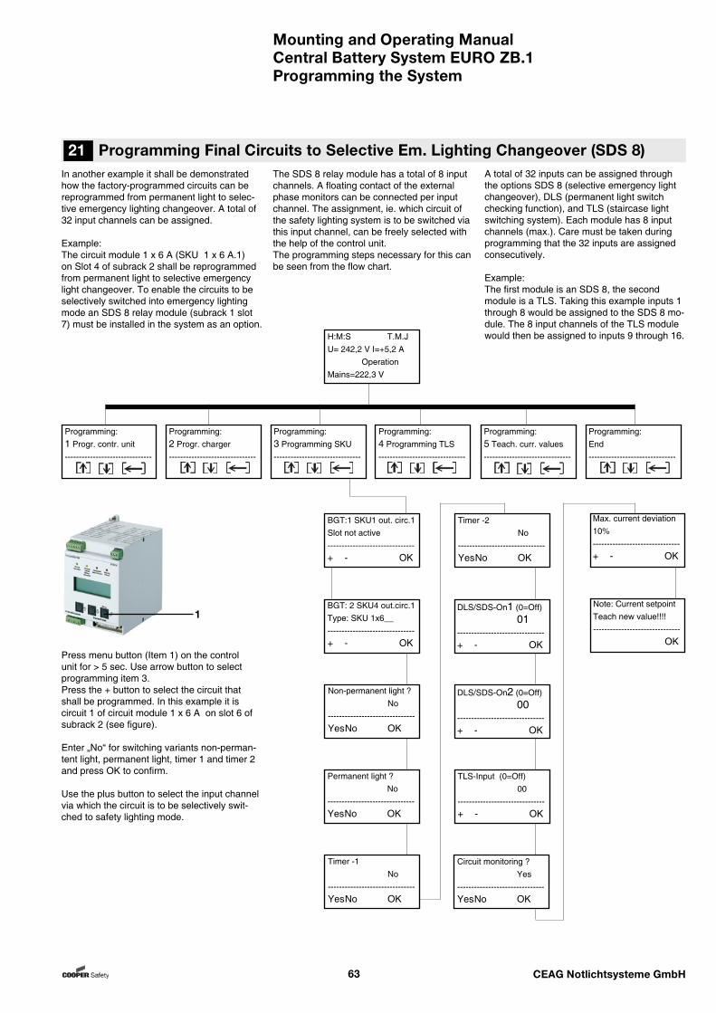
Mounting and Operating ManualCentral Battery System EURO ZB.1
63 CEAG Notlichtsysteme GmbH
In another example it shall be demonstrated how the factory-programmed circuits can be reprogrammed from permanent light to selec-tive emergency lighting changeover. A total of 32 input channels can be assigned.
Example: The circuit module 1 x 6 A (SKU 1 x 6 A.1) on Slot 4 of subrack 2 shall be reprogrammed from permanent light to selective emergency light changeover. To enable the circuits to be selectively switched into emergency lighting mode an SDS 8 relay module (subrack 1 slot 7) must be installed in the system as an option.
A total of 32 inputs can be assigned through the options SDS 8 (selective emergency light changeover), DLS (permanent light switch checking function), and TLS (staircase light switching system). Each module has 8 input channels (max.). Care must be taken during programming that the 32 inputs are assigned consecutively.
Example:The first module is an SDS 8, the second module is a TLS. Taking this example inputs 1 through 8 would be assigned to the SDS 8 mo-dule. The 8 input channels of the TLS module would then be assigned to inputs 9 through 16.
Press menu button (Item 1) on the control unit for > 5 sec. Use arrow button to select programming item 3. Press the + button to select the circuit that shall be programmed. In this example it is circuit 1 of circuit module 1 x 6 A on slot 6 of subrack 2 (see figure).
Enter „No“ for switching variants non-perman-tent light, permanent light, timer 1 and timer 2 and press OK to confirm.
Use the plus button to select the input channel via which the circuit is to be selectively swit-ched to safety lighting mode.
21 Programming Final Circuits to Selective Em. Lighting Changeover (SDS 8)The SDS 8 relay module has a total of 8 input channels. A floating contact of the external phase monitors can be connected per input channel. The assignment, ie. which circuit of the safety lighting system is to be switched via this input channel, can be freely selected with the help of the control unit.The programming steps necessary for this can be seen from the flow chart.
Programming the System
1
BGT:1 SKU1 out. circ.1Slot not active-------------------------------+ - OK
BGT: 2 SKU4 out.circ.1Type: SKU 1x6__-------------------------------+ - OK
Non-permanent light ? No-------------------------------Yes No OK
Permanent light ? No-------------------------------Yes No OK
Timer -1 No-------------------------------Yes No OK
Timer -2 No-------------------------------Yes No OK
TLS-Input (0=Off) 00-------------------------------+ - OK
Circuit monitoring ? Yes-------------------------------Yes No OK
H:M:S T.M.JU= 242,2 V I=+5,2 A OperationMains=222,3 V
Programming:1 Progr. contr. unit-------------------------------
Programming:2 Progr. charger-------------------------------
Programming:3 Programming SKU-------------------------------
Programming:4 Programming TLS-------------------------------
Programming:5 Teach. curr. values-------------------------------
Programming:End-------------------------------
DLS/SDS-On1 (0=Off) 01-------------------------------+ - OK
DLS/SDS-On2 (0=Off) 00-------------------------------+ - OK
Max. current deviation 10%-------------------------------+ - OK
Note: Current setpointTeach new value!!!!------------------------------- OK

Mounting and Operating ManualCentral Battery System EURO ZB.1
64 CEAG Notlichtsysteme GmbH
TLS-Input (0=Off) 01-------------------------------+ - OK
TLS SKU 1x6A
BGT:1 SKU1 out.circ. 1Slot not active-------------------------------+ - OK
BGT: 2 SKU4 out.circ.1Type: SKU 1x6__-------------------------------+ - OK
Non-permanent light ? No-------------------------------Yes No OK
Permanent light ? No-------------------------------Yes No OK
Timer -1 No-------------------------------Yes No OK
Timer -2 No-------------------------------Yes No OK
Control Unit
H:M:S T.M.JU= 242,2 V I=+5,2 A OperationMains=222,3 V
Programming:1 Progr. contr. unit-------------------------------
Programming:2 Progr. charger-------------------------------
Programming:4 Programming TLS-------------------------------
Programming:5 Teach. curr. values-------------------------------
Programming:End-------------------------------
Programming:3 Programming SKU-------------------------------
DLS/SDS-On1 (0=Off) 01-------------------------------+ - OK
DLS/SDS-On2 (0=Off) 00-------------------------------+ - OK
By a further example given here it shall be explained how the factory setting of a circuit switching variant can be changed from perma-nent to staircase lighting operation. A total of 32 input channels can be assigned.
Example: The circuit module 1 x 6 A (SKU 1 x 6 A.1) on Slot 4 of subrack 2 shall be reprogrammed from permanent light to staircase lighting mode. To enable the circuits to be switched via external switching functions in mains operating mode a circuit TLS module (subrack 1 slot 7) must be installed in the system as an option.
A total of 32 inputs can be assigned through the options DLS (permanent light switch chek-king function), TLS (staircase light switching system). Each module has 8 input channels (max.).Care must be taken during programming that the 32 inputs are assigned consecutively.
Example:The first module is a DLS. The second module is a TLS. Taking this example inputs 1 through 8 would be assigned to the DLS module. The 8 input channels of the TLS module would then be assigned to inputs 9 through 16.
Enter „No“ for switching variants non-permantent light, permanent light, ti-mer 1, timer 2, DLS input 1 and DLS input 2 and press OK to confirm.
Use the plus button to select the input channel via which the circuit is to be controlled.
Via input channel 1 of the TLS (Item 1) circuit 1 of circuit module 6 on subrack 2 in mains and battery operating mode shall be switched for a time span ranging between 1 and 15 minutes. The assignment is effected via the freely pro-grammable control unit.
Press the menu button on the control unit for > 5 sec.
Use arrow button to select programming item 3.
Press the + button to select the circuit that shall be programmed.
In this example it is circuit 1 of circuit module 1 x 6 A on slot 6 of subrack 2 (see figure).
22 Programming Final Circuits to Staircase Lighting (TLS)
Programming the System
The TLS staircase lighting function has a total of 8 input channels. For power supply to the glow lamps in the illuminated buttons 0.05 A is available per input channel. The assignment, ie. which circuit of the safety lighting system is to be switched via this input channel, can be freely selected with the help of the control unit.
The programming steps necessary for this can be seen from the flow chart.
1
Max. current deviation 10%-------------------------------+ - OK
Note: Current setpointTeach new value!!!!------------------------------- OK
Circuit monitoring ? Yes-------------------------------Yes No OK
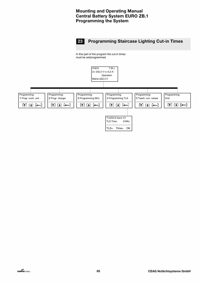
Mounting and Operating ManualCentral Battery System EURO ZB.1
65 CEAG Notlichtsysteme GmbH
In this part of the program the cut-in times must be set/programmed.
23 Programming Staircase Lighting Cut-in Times
Programming the System
H:M:S T.M.JU= 242,2 V I=+5,2 A OperationMains=222,3 V
Programming:1 Progr. contr. unit-------------------------------
Programming:2 Progr. charger-------------------------------
Programming:3 Programming SKU-------------------------------
Programming:4 Programming TLS-------------------------------
Programming:5 Teach. curr. values-------------------------------
Programming:End-------------------------------
TLS/DLS-Input: 01TLS Time: 01Min.-------------------------------TLS+ Time+ OK
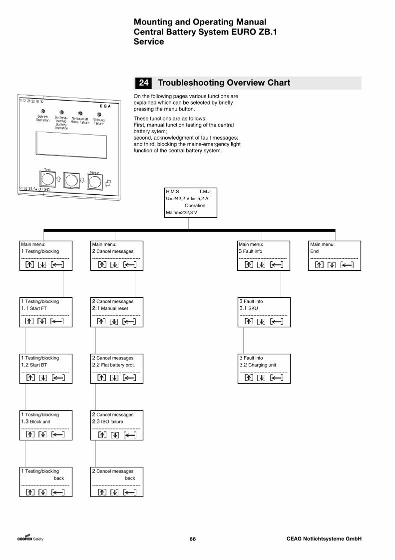
Mounting and Operating ManualCentral Battery System EURO ZB.1
66 CEAG Notlichtsysteme GmbH
On the following pages various functions are explained which can be selected by briefly pressing the menu button.
These functions are as follows: First, manual function testing of the central battery sytem; second, acknowledgment of fault messages; and third, blocking the mains-emergency light function of the central battery system.
24 Troubleshooting Overview Chart
Service
H:M:S T.M.JU= 242,2 V I=+5,2 A OperationMains=222,3 V
Main menu:1 Testing/blocking-------------------------------
Main menu:End-------------------------------
1 Testing/blocking1.1 Start FT-------------------------------
1 Testing/blocking1.2 Start BT-------------------------------
1 Testing/blocking1.3 Block unit-------------------------------
1 Testing/blocking back-------------------------------
2 Cancel messages2.1 Manual reset-------------------------------
2 Cancel messages2.2 Flat battery prot.-------------------------------
2 Cancel messages2.3 ISO failure-------------------------------
2 Cancel messages back-------------------------------
Main menu:2 Cancel messages-------------------------------
3 Fault info3.1 SKU-------------------------------
3 Fault info3.2 Charging unit-------------------------------
Main menu:3 Fault info-------------------------------
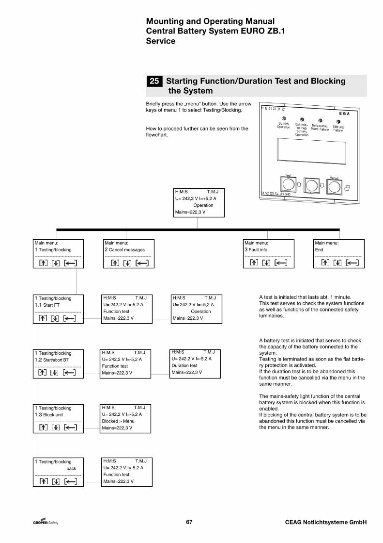
Mounting and Operating ManualCentral Battery System EURO ZB.1
67 CEAG Notlichtsysteme GmbH
Briefly press the „menu“ button. Use the arrow keys of menu 1 to select Testing/Blocking.
How to proceed further can be seen from the flowchart.
A test is initiated that lasts abt. 1 minute.This test serves to check the system functions as well as functions of the connected safety luminaires.
A battery test is initiated that serves to check the capacity of the battery connected to the system.Testing is terminated as soon as the flat batte-ry protection is activated. If the duration test is to be abandoned this function must be cancelled via the menu in the same manner.
The mains-safety light function of the central battery system is blocked when this function is enabled. If blocking of the central battery system is to be abandoned this function must be cancelled via the menu in the same manner.
Service
25 Starting Function/Duration Test and Blocking the System
Main menu:1 Testing/blocking-------------------------------
Main menu:2 Cancel messages-------------------------------
H:M:S T.M.JU= 242,2 V I=+5,2 A OperationMains=222,3 V
Main menu:3 Fault info-------------------------------
Main menu:End-------------------------------
1 Testing/blocking back-------------------------------
H:M:S T.M.JU= 242,2 V I=-5,2 AFunction testMains=222,3 V
1 Testing/blocking1.3 Block unit-------------------------------
H:M:S T.M.JU= 242,2 V I=-5,2 ABlocked > MenuMains=222,3 V
1 Testing/blocking1.2 Start/abort BT-------------------------------
H:M:S T.M.JU= 242,2 V I=-5,2 AFunction testMains=222,3 V
H:M:S T.M.JU= 242,2 V I=-5,2 ADuration testMains=222,3 V
1 Testing/blocking1.1 Start FT-------------------------------
H:M:S T.M.JU= 242,2 V I=-5,2 AFunction testMains=222,3 V
H:M:S T.M.JU= 242,2 V I=+5,2 A OperationMains=222,3 V
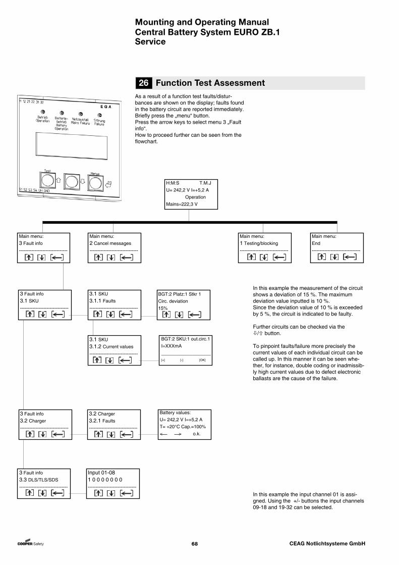
Mounting and Operating ManualCentral Battery System EURO ZB.1
68 CEAG Notlichtsysteme GmbH
As a result of a function test faults/distur-bances are shown on the display; faults found in the battery circuit are reported immediately.Briefly press the „menu“ button.Press the arrow keys to select menu 3 „Fault info“. How to proceed further can be seen from the flowchart.
Service
26 Function Test Assessment
In this example the measurement of the circuit shows a deviation of 15 %. The maximum deviation value inputted is 10 %. Since the deviation value of 10 % is exceeded by 5 %, the circuit is indicated to be faulty.
Further circuits can be checked via the / button.
To pinpoint faults/failure more precisely the current values of each individual circuit can be called up. In this manner it can be seen whe-ther, for instance, double coding or inadmissib-ly high current values due to defect electronic ballasts are the cause of the failure.
In this example the input channel 01 is assi-gned. Using the +/- buttons the input channels 09-18 and 19-32 can be selected.
Main menu:End-------------------------------
Main menu:2 Cancel messages-------------------------------
Main menu:3 Fault info-------------------------------
H:M:S T.M.JU= 242,2 V I=+5,2 A OperationMains=222,3 V
3 Fault info3.1 SKU-------------------------------
3.1 SKU3.1.1 Faults-------------------------------
3.1 SKU3.1.2 Current values-------------------------------
Main menu:1 Testing/blocking-------------------------------
3 Fault info3.3 DLS/TLS/SDS-------------------------------
Input 01-081 0 0 0 0 0 0 0-------------------------------
3 Fault info3.2 Charger-------------------------------
3.2 Charger3.2.1 Faults-------------------------------
Battery values:U= 242,2 V I=+5,2 AT= +20°C Cap.=100% < > o.k.
BGT:2 SKU:1 out.circ.1I=XXXmA___________________
[+] [-] [OK]
BGT:2 Platz:1 Stkr 1 Circ. deviation 15%
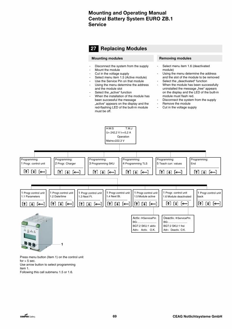
Mounting and Operating ManualCentral Battery System EURO ZB.1
69 CEAG Notlichtsysteme GmbH
Mounting modules
- Disconnect the system from the supply- Mount the module- Cut in the voltage supply- Select menu item 1.5 (Active module)- Use the Service Pin on that module- Using the menu determine the address and the module slot- Select the „active“ function- When the installation of the module has been successful the message „active“ appears on the display and the red-flashing LED of the built-in module must be off.
Removing modules
- Select menu item 1.6 (deactivated module)- Using the menu determine the address and the slot of the module to be removed- Select the „deactivated“ function- When the module has been successfully uninstalled the message „free“ appears on the display and the LED of the built-in module must flash red.- Disconnect the system from the supply- Remove the module- Cut in the voltage supply
Press menu button (Item 1) on the control unit for > 5 sec.Use arrow button to select programming item 1.Following this call submenu 1.5 or 1.6.
27 Replacing Modules
Service
1
1 Progr.control unit1.1 Parameters-------------------------
H:M:S T.M.JU= 242,2 V I=+5,2 A OperationMains=222,3 V
Programming:1 Progr. control unit-------------------------------
Programming:2 Progr. Charger-------------------------------
Programming:3 Programming SKU-------------------------------
Programming:4 Programming TLS-------------------------------
Programming:5 Teach curr. values-------------------------------
Programming:End-------------------------------
1 Progr. control unit1.6 Module deactivated-------------------------------
Activ.ServicePinBG:.........................BGT:2 SKU:1 aktiv Adr+ Activ. O.K.
Deactiv.ServicePinBG:.........................BGT:2 SKU:1 frei Adr+ Deactiv. O.K.
1 Progr.control unit1.2 Date/time------------------------
1 Progr.control unit1.3 Next Ft.------------------------
1 Progr.control unit1.4 Next Bt.-----------------------
1 Progr.control unit1.5 Module active-------------------------
1 Progr.control unitback------------------------
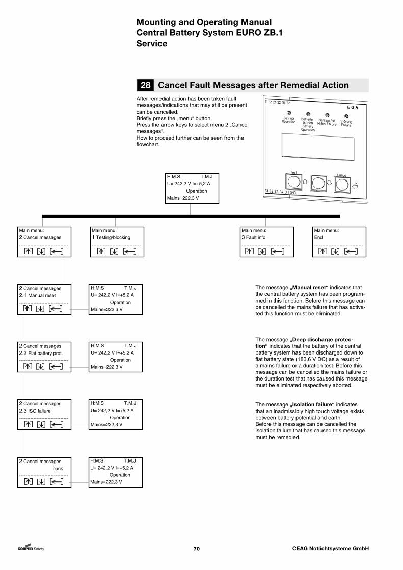
Mounting and Operating ManualCentral Battery System EURO ZB.1
70 CEAG Notlichtsysteme GmbH
After remedial action has been taken fault messages/indications that may still be present can be cancelled.Briefly press the „menu“ button. Press the arrow keys to select menu 2 „Cancel messages“. How to proceed further can be seen from the flowchart.
The message „Manual reset“ indicates that the central battery system has been program-med in this function. Before this message can be cancelled the mains failure that has activa-ted this function must be eliminated.
The message „Deep discharge protec-tion“ indicates that the battery of the central battery system has been discharged down to flat battery state (183.6 V DC) as a result of a mains failure or a duration test. Before this message can be cancelled the mains failure or the duration test that has caused this message must be eliminated respectively aborted.
The message „Isolation failure“ indicates that an inadmissibly high touch voltage exists between battery potential and earth.Before this message can be cancelled the isolation failure that has caused this message must be remedied.
28 Cancel Fault Messages after Remedial Action
Service
Main menu:2 Cancel messages-------------------------------
2 Cancel messages2.1 Manual reset-------------------------------
Main menu:1 Testing/blocking-------------------------------
H:M:S T.M.JU= 242,2 V I=+5,2 A OperationMains=222,3 V
H:M:S T.M.JU= 242,2 V I=+5,2 A OperationMains=222,3 V
H:M:S T.M.JU= 242,2 V I=+5,2 A OperationMains=222,3 V
H:M:S T.M.JU= 242,2 V I=+5,2 A OperationMains=222,3 V
2 Cancel messages back-------------------------------
2 Cancel messages2.3 ISO failure-------------------------------
2 Cancel messages2.2 Flat battery prot.-------------------------------
H:M:S T.M.JU= 242,2 V I=+5,2 A OperationMains=222,3 V
Main menu:3 Fault info-------------------------------
Main menu:End-------------------------------

Mounting and Operating ManualCentral Battery System EURO ZB.1
71 CEAG Notlichtsysteme GmbH
29 VDE Requirements Governing Telecommunication Contacts and Buzzers
Service
The system has 3 floating signalling contacts (relay outputs) and a buzzer built into the unit.
Max. Contact strain: 24 V; 0.5 A
Rest position of relais contacts: 11/12 = closed 21/22 = open 31/32 = open
Contacts: 11/12 21/22 31/32 Signalling status: Collective Operational Battery fault readiness operation
Operating status:Mains operation ................... 0 X 0Mains failure S3/S4 ............. 0 X 0Charging failure ................... X X 0Circuit failure ....................... X X 0Luminaire failure .................. X X 0Sum failure .......................... X X 0Deep discharge protection .. X 0 0ISO failure ............................ 0 X 0Function test........................ 0 0 XDuration test ........................ 0 0 X
X = closed 0 = open
Note:Observe national rules and regulations governing the indicating and signalling behaviour when using a remote switch or a remote indicator for emergency lighting systems.
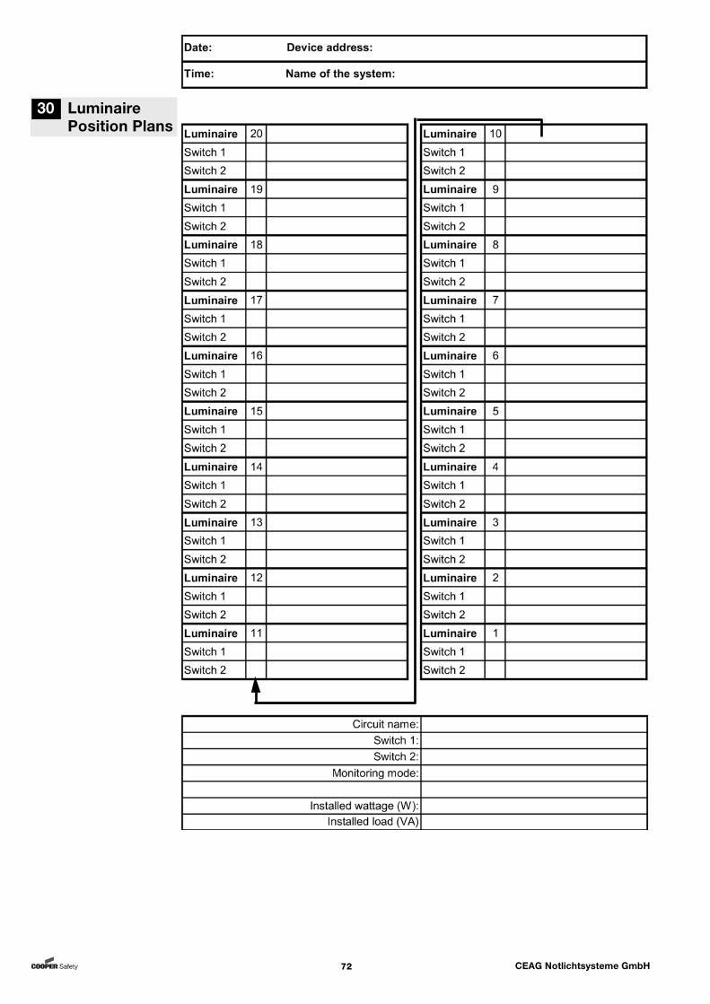
Mounting and Operating ManualCentral Battery System EURO ZB.1
72 CEAG Notlichtsysteme GmbH
30 Luminaire Position Plans
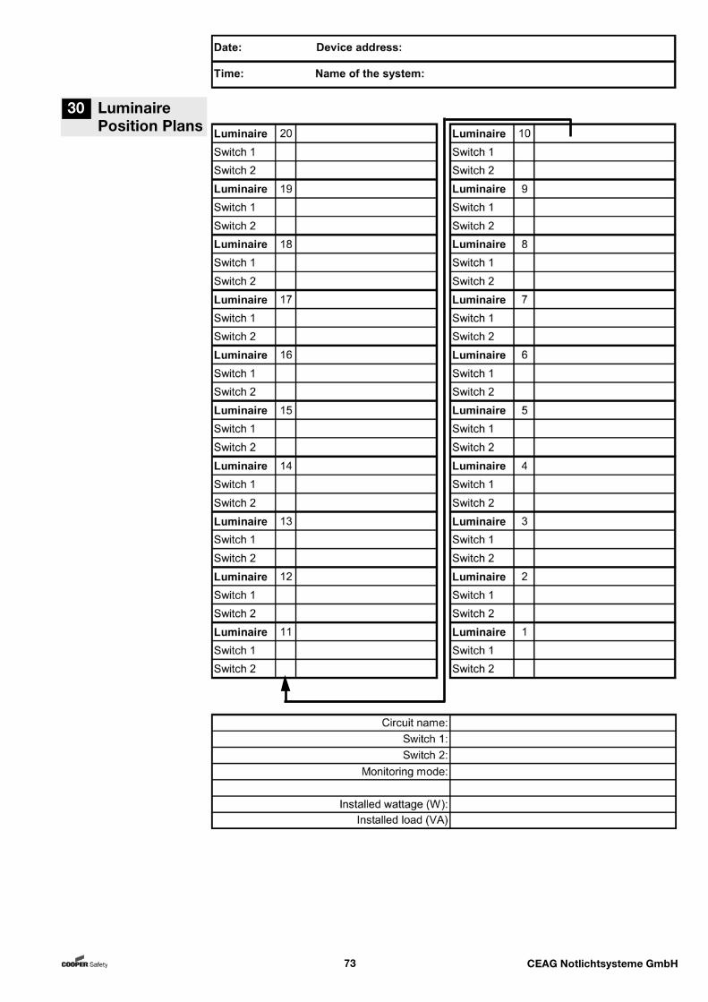
Mounting and Operating ManualCentral Battery System EURO ZB.1
73 CEAG Notlichtsysteme GmbH
30 Luminaire Position Plans
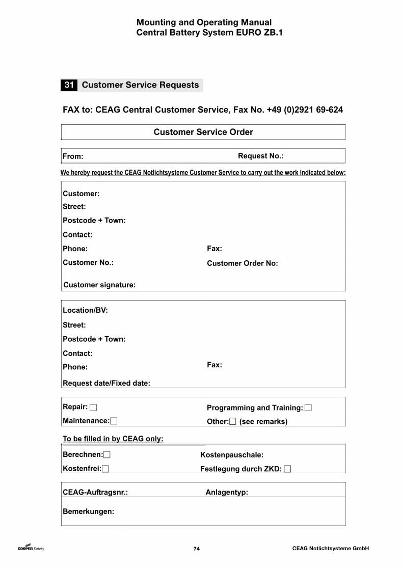
Mounting and Operating ManualCentral Battery System EURO ZB.1
74 CEAG Notlichtsysteme GmbH
31 Customer Service Requests

Mounting and Operating ManualCentral Battery System EURO ZB.1
75 CEAG Notlichtsysteme GmbH
300 80 001 416_E/XXX/01.13/XXX