moulded polyester enclosures minipol · pdf filemoulded polyester enclosures minipol system ...
TRANSCRIPT
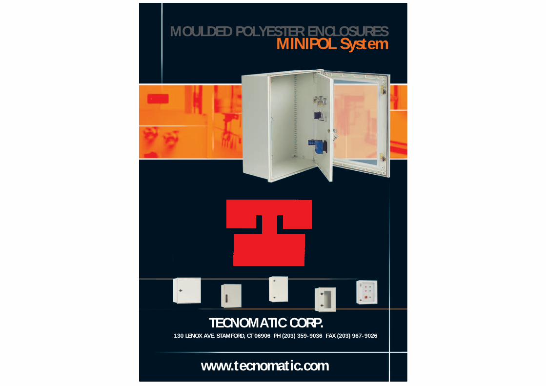
MOULDED POLYESTER ENCLOSURESMINIPOL System
www.tecnomatic.com
TECNOMATIC CORP.130 LENOX AVE. STAMFORD, CT 06906 PH (203) 359-9036 FAX (203) 967-9026

THE MINIPOL RANGE
A system of cabinets made of hot moulded
fibreglass reinforced polyester (GRP).
The cabinets are halogen free. They can be used
in all kinds of communication, electrical,
pneumatical and hydraulical installations.
The base is made in one piece, guaranteeing
optimal availability in the interior
and increasing the impact resistance.
The cabinets offer optimal security for humans
and animals because of the double
isolation characteristics.
The cabinets are available with opaque
or transparent doors in 7 different sizes.
They are symmetrical and reversible in many
cases. The wide range of accessories gives
an extra dimension to the Minipol range.

NO HIGROSCÓPICO
La absorción de agua esnula.
MINIPOL SYSTEM
7
ELEVADA RESISTENCIA AL IMPACTO
Soporta impactos de20 Joules (IK10).
CHARACTERISTICSOF THE MATERIAL
The cabinets are made of hotmoulded fibreglass reinforcedpolyester (GRP). The cabinets arehalogen free with a RAL 9002grey as standard. The material’sperformance qualities are veryhigh and the essentialcharacteristics are the following:
HIGH IMPACT STRENGTH
SELF EXTINGUISHABLE
DOUBLE ISOLATION
CORROSION RESISTANT
NO WATER ABSORPTION
EASY TO MACHINE
EASY AND FAST FITTING
INSENSITIVE TO OUTDOORENVIRONMENT
LIGHT
AUTOEXTINGUIBLES
No propaga la llama.
DOBLE AISLAMIENTO
Proporcionan unaexcelente proteccióncontra los contactos.
RESISTENTES A LA CORROSIÓN
No precisa ningúnacabado especial.
FACILIDAD DE MECANIZACIÓN
No precisan ningunaherramienta especial.
RAPIDEZ Y SIMPLICIDAD DE MONTAJE
Permite realizar losdiversos acoplamientosde forma rápida y simple.
RESISTENTES A LA INTEMPERIE
Resistente a lasvariaciones ambientales.
De fácil y cómodomanejo e instalación.
LIGEROS
POLYESTERBETTER
MINIPOL CERTIFICATIONS
PROTECTION DEGREEIP 66 according to theUNE 20324, EN 60529and IEC 60529 norms.
IMPACT RESISTANCEIK10 20 J according tothe UNE-EN 50102and IEC 62262 norms.
SELF EXTINGUISHABLE960° according to theUNE-EN 60695-2-1/0and IEC 60695-2-10 norms.
DOUBLE ISOLATIONAccording theUNE-EN 60439-1and IEC 60439-1 norms.
THERMIC CLASSE 150° according to theUNE 21305, EN-HD 566S1and 60085 norms.
APPROVALSAND CERTIFICATESLaboratori General d´Assaigi Investigacions
HIGH IMPACT STRENGTH
Can take hits up to20 Joules, IK 10.
NON HYDROSCOPIC
Does not absorb water.
SELF-EXTINGUISHABLE
Does not feedthe flames.
EASY AND FAST FITTING
Allows fast and easyfitting.
LIGHT
Comfortableand easy handlingand installation.
DOUBLE ISOLATION
Provides an excellentprotection againstcontacts.
CORROSION RESISTANT
Does not require anyfinishing.
EASY TO MACHINE
No special toolis needed.
INSENSITIVE TO OUTDOORENVIRONMENT
Resistant to climatechanges.
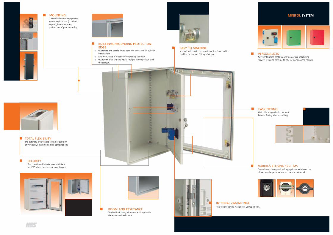
BUILT-IN/SURROUNDING PROTECTIONEDGEGuarantee the possibility to open the door 180° in built-in installations.Avoid entrance of water while opening the door.Guarantee that the cabinet is straight in comparison withthe surface.
EASY FITTINGQuick fixture guides in the back.Permits fitting without drilling.
EASY TO MACHINEVertical patterns in the interior of the doors, whichenables the correct fitting of devices.
SECURITYThe chassis and interior door maintainan IP20 when the external door is open.
TOTAL FLEXIBILITYThe cabinets are possible to fit horizontallyor vertically, obtaining endless combinations.
ROOM AND RESISTANCESingle-block body, with even walls optimisinthe space and resistance.
MOUNTING3 standard mounting systems;mounting brackets (standardsupply), Pole-mountingand on top of pole mounting.
VARIOUS CLOSING SYSTEMSSeven basic closing and locking systems. Whatever typeof lock can be personalized to customer demand.
PERSONALIZEDSave installation costs requesting our pre-machiningservice. It is also possible to ask for personalized colours.
MINIPOL SYSTEM
INTERNAL ZAMAK INGE180° door opening warranted. Corrosion free.

MINIPOL SYSTEM
DIFFERENT APPLICATIONS
The Minipol range can be orderedwith two types of doors, opaqueor transparent.
OPAQUE DOORAllows outdoor installation
TRANSPARENT DOORThe devices can be seen whencombined with inner door andchassis. The IP level is kept.
APPLICATIONSMINIPOL
MINIPOLApplied in the chemicaland cement industry.
MINIPOL Applied in access control and security systems.
MINIPOLApplied for light,sound and hydraulicalcontrol etc.
Minipol in a skiing zone(extreme conditions).
MINIPOLApplied to regulate awater pump.
MINIPOL Applied in weather stations, astronomical and theircommunications.

Flat doorStandard lock 2x double bit DIN 3.0 mmSupplied with all the accessories enabling it to befixed to a wall
MIP-325(1 double bar lock)
MIP-43 MIP-44 MIP-54 MIP-64 MIP-65 MIP-86
Flat doorThree point closing device, 1x double bit DIN 3.0 mmSupplied with all the accessories enabling it to befixed to a wall
- MIP-43/3P MIP-44/3P MIP-54/3P MIP-64/3P MIP-65/3P MIP-86/3P
Flat doorThree point closing device with swing door,1x double bit DIN 3.0 mmSupplied with all the accessories enabling it to befixed to a wall
- MIP-43/EKDB MIP-44/EKDB MIP-54/EKDB MIP-64/EKDB MIP-65/EKDB MIP-86/EKDB
Transparent doorStandard lock 2x double bit DIN 3.0 mmSupplied with all the accessories enabling it to befixed to a wall
MIP-325PT(1 double bar lock)
MIP-43PT MIP-44PT MIP-54PT MIP-64PT MIP-65PT MIP-86PT
Transparent doorThree point closing device, 1x double bit DIN 3.0 mmSupplied with all the accessories enabling it to befixed to a wall
- MIP-43PT/3P MIP-44PT/3P MIP-54PT/3P MIP-64PT/3P MIP-65PT/3P MIP-86PT/3P
Transparent doorThree point closing device with swing door,1x double bit DIN 3.0 mmSupplied with all the accessories enabling it to befixedto a wall
- MIP-43PT/EKDB MIP-44PT/EKDB MIP-54PT/EKDB MIP-64PT/EKDB MIP-65PT/EKDB MIP-86PT/EKDB
MEASURES (mm) 300 x 250 x 140 400 x 300 x 200
MINIPOL SYSTEM
400 x 400 x 200 500 x 400 x 200 600 x 400 x 230 600 x 500 x 230 800 x 600 x 300
PRODUCT RANGEMINIPOL

Polyester base plate4 mm thickness
PBP-325 PBP-43 PBP-44 PBP-54 PBP-64 PBP-65 PBP-86
Metal base plateRAL 2000 colour2 mm thickness
PBM-325 PBM-43 PBM-44 PBM-54 PBM-64 PBM-65 PBM-86
Metal base plateZinced steel2 mm thickness
PBM-325/B PBM-43/B PBM-44/B PBM-54/B PBM-64/B PBM-65/B PBM-86/B
Perforated mounting plate (TELEQUICK)Zinced steel plateAllows quick fixing of devices by using M4, M5and M6 screw nuts
PBR-325 PBR-43 PBR-44 PBR-54 PBR-64 PBR-65 PBR-86
Adjustable and hinged polyester base plateSet of several mounting profiles for different depthsand a hinged base plate of polyester
- PGD-43 PGD-44 PGD-54 PGD-64 PGD-65 PGD-86
Internal doorMade of polyester
- PI-43 PI-44 PI-54 PI-64 PI-65 PI-86
MEASURES (mm) 300 x 250 x 140 400 x 300 x 200
MINIPOL SYSTEM
400 x 400 x 200 500 x 400 x 200 600 x 400 x 230 600 x 500 x 230 800 x 600 x 300
see page 23
ACCESSORIESMINIPOL

Chassis for the fitting of modular devicesMade of a chassis, die cast plates and DIN profilesfor fixing of the devicessee page 22
Number of modulesNumber of files
Number of modulesNumber of files
-
--
MIP-43/CH24
242x12
MIP-44/CH36
362x18
MIP-54/CH54
543x18
MIP-64/CH54
543x18
MIP-65/CH69
693x23
MIP-86/CH116
1164x29
-
--
-
--
-
--
-
--
-
--
-
--
MIP-86/CH145
1455x29
Spare parts:Die cast platesKnockouts for DIN SwitchgearFor modular chassisPlates in self-extinguishing insulating material
152 mm height cover 178 mm height cover202 mm height cover
---
-CC-300/178
-
CC-400/152CC-400/178CC-400/202
CC-400/152CC-400/178CC-400/202
CC-400/152CC-400/178CC-400/202
CC-500/152-
CC-500/202
CC-600/152CC-600/178CC-600/202
Spare parts:Mounting plate for modular chassisFor the fixing of non-modular switchgearMade of galvanised steel
152 mm height base plate178 mm height base plate202 mm height base plate
---
-PB-300/178
-
PB-400/152PB-400/178PB-400/202
PB-400/152PB-400/178PB-400/202
PB-400/152PB-400/178PB-400/202
PB-500/152-
PB-500/202
PB-600/152PB-600/178PB-600/202
Pole mountingFor external, provisional installations as constructionsites or congressesSet of plates and adjustable clampsBrackets and profiles of galvanized steel
FP-250 FP-300 FP-400 FP-400 FP-400 FP-500 FP-600
MEASURES (mm) 300 x 250 x 140 400 x 300 x 200
MINIPOL SYSTEM
400 x 400 x 200 500 x 400 x 200 600 x 400 x 230 600 x 500x 230 800 x 600 x 300
ACCESSORIESMINIPOL

MINIPOL SYSTEM
ACCESSORIESMINIPOL
SURFACE MOUNTING
Wall fixing set.Directly to the wall by the means of head-insulatedscrews.Ref. TF-MIP
Set of adjustable brackets.Set of 4 to every cabinet.Ref. POF
SCREW CLIPS
To fix devices with the help of TELEQUICK.
Screw clip M4 Ref. CLIP-M4Screw clip M5 Ref. CLIP-M5Screw clip M6 Ref. CLIP-M6
SHUTTERS
Set of shutters enabling partial covering of the window for automatic fuses.Fast fixing.Made of a self-extinguishing and isolating material.
Set of three pieces of one module two for 0.5 Ref. 0E-1
DERIVATION BAR
Terminal bars for the derivation of the neutral and earth contact. Includes thebar and its support.
Terminal bars of 3 x 16 + 4 x 10 mm2 Ref. DPT1N
ADJUSTABLE BASE PLATE
Set of four profiles for the adjustment of the base plate, to different depths.Fast fixing to the cabinet.Made of galvanized steel.
Cabinet kit for MIP-43, MIP-44 and MIP-54 Ref. PDP-200Cabinet kit for MIP-64 and MIP-65 Ref. PDP-230Cabinet kit for MIP-86 Ref. PDP-300
CLOSING PLATE
Are used for the entrance of cables, cable glands etc.Made in polyester.
For 250 width Ref. U-402For 300 width Ref. U-403For 400/500 width Ref. U-404
COUPLING PIECES
Used for vertical or horizontal fitting of enclosures of same depth.Made in polyester.
VERTICAL FITTINGFor 250 width cabinets Ref. UM-420VFor 300 width cabinets Ref. UM-430VFor 400/500 width cabinets Ref. UM-440V
HORIZONTAL FITTINGFor 300 height cabinets Ref. UM-430HFor 400 to 800 height cabinets Ref. UM-440H
VENTILATION DEVICE
To allow ventilation in the cabinet.Made in Polyester.
Standard size RAL-9002 Ref. DV/C
Normal size RAL-7035 Ref. DVG
DRAIN VALVE
Enabling drainage of possible condensation.Made in polyester.
For all types of boxes. Ref. DP
SUPPORTING POLE
For protection of incoming and outgoing cables.Specially for off the ground instalations, camping sites, marinas, etc.Main support in stainless steel and PVC covers.Easy fitting.
Supporting pole Ref. PFS/MI

CONFIGURA
Our cabinets and boxes can be personalized ondemand. Adapted to your requirements ofinstallation and mounting.
We process your enclosure with our automaticrobot system. Making whatever perforation ormechanization on the front or side. Individual ormultiple round, square or special holes. You canget what you need in all our cabinets and boxes.Adapting ourselves to your needs so that you canlower your production and handle costs.
Whatever box or cabinet can be made in whatevercolor you might need, depending on the needs inthe installation area.For short production lines or for long lines.
PERSONALISATION OF ENCLOSURE SERVICEWE ADAPT TO YOUR REQUIREMENTS
The difference in price between a standard product and anon-standard can be minimal in a long production line.
In function of our new production system, the delivery timesdo not change considerably in comparison with the standardproduct.
LOCKSMINIPOL
LOCKS
Wide range of locks adaptables to the cabinets.The standard is the double bit lock.
Double bit DIN 3.0 mm.Ref. PDB
Triangular screw 11 mm.Ref. PTT
Manual with key lock.Ref. PCM
Manual with key lock 3P.Ref. PCM/3P
Retractable closing with small pump double bar.Ref. EKDB
Stainless steel padlock in (PDB and PTT).Padlocking device in zinced steel.Ref. EC
Stainless steel padlock.Ref. PCC
Lock systems for the internal door.Key lock.Ref. CPI-LL
Screw lock.Ref. CPI-DE

MINIPOL SYSTEM
INTERNAL DOOR
For the fixing of signal and measurement elements. The protection grade and the double isolation of thecabinet are kept intact. Event though the accessories and the fixing parts are of metal.
This unit comes in a kit, to be fitted into the cabinet by the user.The fixing of the unit is fast, simple and safe.
Permits the installation of the fixed base plate. The adjustable plates and the modular switchgear cannotbe used.
The internal door can be hinged on both sides. This means that the door can be put on the right or leftside. The door opens 90° and is marked in the interior, making mechanization and fitting of signal lamps,pushbuttons etc easier.The internal door’s closing system is done with a lock and key to hinder unauthorized people (Other kindsof looks can be ordered).
KIT COMPOSITION
The kit has all the pieces necessary to fit the internal door:
4 inserts for the fixing of the set.Closing profile with screws and fixing rings, fitted to the inserts.Internal door with hinges and locking device with corresponding screws and fixing rings for the locking profile.
CHASSIS FOR THE INSTALLATION OF MODULAR SWITCHGEAR
A chassis system has been developed for modular switchgear. It is supplied in a kit, which permits quickfitting and quality.
KIT ADVANTAGES
All fitting and cabling is made on the outside of the cabinet, which makes maintenance extension easier.The fixing of the whole cabinet set is quick, simple and safe.The support rails of the modular switchgear can be regulated to seven different heights.Base plates and die cast plates are available for non-modular switchgear.
KIT COMPOSITION
The kit composes of all the necessary pieces to make the mounting of the modular switchgear, with themaximum number of rows depending on the height of the cabinet. The pieces are the following:
2 lateral pieces.One support profile for every row of modular switchgear.One bracket for every support profile.4 bases for the fitting of the chassis inside the cabinet.4 metallic inserts for the fixing of the bases.1 die cast plate for every for every support profile.All the necessary screws for the installation.Accessory (base plate).
COVERS
Covers included in the kit have two purposes: keeping IP with open doors, and good aesthetic performance.
The design system and chassis assembly, allows with the same pieces included in the kit; with no need tomake any mechanization, changes in distances between switchgear or, offering greater or smaller spacefor wiring.
The diverse assemblies that can be made are indicated in the kit assembly Instructions.
AB
202
C 152E
D
178

MINIPOL SYSTEM
TYPE A B C D E F GMIP-325 300 250 140 276 212 120 110MIP-43 400 300 200 370 262 180 170MIP-44 400 400 200 370 362 180 170MIP-54 500 400 200 470 362 180 170MIP-64 600 400 230 570 362 210 200MIP-65 600 500 230 570 462 210 200Mip-86 800 600 300 770 562 280 270
TYPE A B E F
MIP-325 220 115 35 75MIP-43 281 141 52 80MIP-44 281 221 52 90MIP-54 381 221 52 90MIP-64 481 221 52 90MIP-65 481 321 52 90Mip-86 681 421 52 90
DIMENSIONS mm
DIMENSIONS mm
CABINET DIMENSIONS
TYPE A B C DMIP-325 268 213 248 175MIP-43 358 260 338 222MIP-44 358 360 338 322MIP-54 458 360 438 322MIP-64 558 360 538 322MIP-65 558 460 538 422Mip-86 754 556 734 518
TYPE A B
MIP-43 366 258MIP-44 366 358MIP-54 466 358MIP-64 566 358MIP-65 566 458MIP-86 766 658
DIMENSIONS mm
DIMENSIONS mm
FITTING TYPE
2 vertical coupling 250 mm wide UM-420V3 vertical coupling 300 mm wide UM-430V
4 vertical coupling 400/500 mm wide UM-440V
3 horizontal coupling 300 mm high UM-430H
4 horizontal coupling 400/500/600/800 mm high UM-440H
FITTING
The Minipol range permits severalcabinets to be fitted together withthe help of coupling pieces.
TRANSPARENT DOOR
BASE PLATE
INTERNAL DOOR
FITTING OF CABINETS

MINIPOL SYSTEM
Mobile or portable equipment or applian-ces used or stored in sheltered premises.
Indoors in premises for storage and main-tenance purposes where connections arenot exposed to the risk of immersion orchemicals.
Covered construction sites shelteredagainst weathering though exposed tosplashing water.
In sheltered premises protected againstthe weather, though exposed to splashing,without high-connected loads.
In sheltered locations, in indoor premisesserving for storage and maintenance.
In sheltered storehouses, workshops formaintenance, minor assembly and mould-ing.
Locations without high humidity or ambi-ent pollution serving for assembly, mould-ing, maintenance and storage.
Electrical connections executed abovefloor level.
In sheltered locations such as docks, repairshops, offices etc.
In sheltered locations, hangars, repairshops, storehouses.
Indoor use in repair shops, etc.
Outdoor installation of pumping, ventilation,drying equipment.
On premises without risk of explosions butwhere the connections are exposed to chemi-cals and subject to possible immersion.
In outdoor construction sites where the con-nections are left on humid ground exposed tofreezing, dust and weathering.
Outdoor systems exposed to rain, snow, mud,freezing and other critical weather condi-tions, where high load for lighting installa-tions, TV or audio is expected.
In locations subject to washing by hosingdown and where connections are subject toheavy duty.
In rolling mills, foundries, blast furnaces, etc.,where the connections are exposed to dust,metal swarf, coolants and are subject tovibrations and impact.
On premises subject to cleaning by means ofchemical solvents. Also where heavy loadsrequire high safety in connections.
Electrical connections executed under raisedfloors with risk of immersion. Where heavyloads require high safety in connections.
Quays, docks, piers, etc. Where there is risk ofhigh waves and partial flooding.
Outdoors for the connection between mobileor portable appliances and aircraft
In all locations with risk of flooding and foroutdoor use with pumps, aeration and venti-lation systems.
FIELD OF USE IP43/44 IP55/67
GUIDELINE FOR THE USE OF INDEX PROTECTION DEGREES
FIRST CHARACTERISTIC NUMERALProtection of people against access to hazardous parts (see additionalletter) and protection against solid foreign objects.
SECOND CHARACTERISTIC NUMERALProtection against harmful intake of water.
ADDITIONAL LETTER
If the actual protection against access to hazardous parts is higher thanthat indicated by the first characteristic numeral.
SUPPLEMENTARY LETTERS
To provide ulterior information on the material.
DEGREES OF PROTECTIONACCORDING TO UNE 20324 IEC-EN 60529
SOLIDFOREIGNOBJECTS
ACCESS TOHAZARDOUS
PARTS
Non-protected.
Protected against solid foreign objects of50 mm Ø and larger (i.e. the back of thehand).
Protected against solid foreign objects of12.5 mm Ø and larger (i.e. with a finger).
Protected against solid foreign objects of2.5 mm Ø and larger (i.e. access to haz-ardous parts with a tool).
Protected against solid foreign objects of1.0 mm Ø and larger (i.e. access to haz-ardous parts with a wire).
Dust intake is not totally prevented, butdust shall not penetrate in such a quantityto interfere with satisfactory operation ofthe apparatus or to impair safety.
Dust-tight. No dust-intake.
Non-protected.
Protected against vertically fallingwater drops
Protected against vertically fallingwater drops when enclosure is tiltedup to 15°.
Water sprayed at an angle up to 60°on either side of the vertical shallhave no harmful effects.
Water splashed against the enclosurefrom any direction shall have noharmful effects.
Water projected in jets against theenclosure from any direction shallhave no harmful effects.
Protected against powerful waterjets.
Protected against the effects of tem-porary immersion of water.
Protected against the effect of con-tinuous immersion of water
TEST
LETTER SIGNIFICANCE LETTER SIGNIFICANCE
Protected against access with the back of the hand. Theaccess probe, sphere of 50 mm Ø shall have adequateclearance from hazardous parts.
Protected against access with a finger. The jointed testfinger of 12 mm Ø, 80 mm length shall have adequateclearance from hazardous parts.
aProtected against access with a tool. The access probeof 2.5 mm Ø, 100 mm length shall have adequateclearance from hazardous parts.
Protected against access with a wire. The access probeof 1.0 mm Ø, 100 mm length shall have adequate clea-rance from hazardous parts.
High-voltage apparatus.
Tested for harmful effects due to water intake when themovable parts of the equipment (e.g. the rotor of therotating machine) are in motion.
aTested for harmful effects due to water intake when themovable parts of the equipment (e.g. the rotor of therotating machine) are stationary.
Suitable for use under specified weather conditions andprovided with additional protective features or processes.
AGRICULTURE
CHEMICAL INDUSTRY
CONSTRUCTION SITESAND SHIPYARDS
SPORTS COMPLEXESAND OTHER PLACES OFPUBLIC ENTERTAINMENT,TV AND FILM STUDIOS
FOOD INDUSTRY
HEAVY INDUSTRY
LIGHT INDUSTRY
INSTALLATIONSFOR EDP CENTRES
PORTS
AIRPORTS
WATER TREATMENTPLANTS

PLASTIC MATERIALS
Plastic materials are used for many applications. Finished products are obtained by using heating processes.They have a molecular structure (made) of long chains of polymers created by the interaction of several mol-ecules (monomers) or pair of molecules.Distinction between thermoplastics and thermo sets has to be made.
THERMOPLATICS
Its transformation is carried out by hot mould injection. The obtained pieces of thermoplastic, can bemoulded a number of times. Most thermoplastics are soluble in normal organic solvents.
THERMOSETS
Its transformation is carried out by hot mould compression. Finished products cannot be remoulded andthey are insoluble, due to the particular molecular structure. This type of plastic cannot be hot welded andis practically insoluble in most solvents found on the market.In some cases, it is possible to use specific solvents.
PLASTICS ADVANTAGES
Double insulation gives perfect safety against direct and indirect contacts.Frame does not need earthing.Unlike metal, plastic does not rust.Enclosures are homogeneous, no maintenance is required.Because of its lightweight plastic enclosures can be easily machined, handled and installed.
MINIPOL SYSTEM
MECHANICALImpact strength ISO 179 KJ/m2 55 No rupture 40 40
Notched impact strength ISO 179 KJ/m2 55 30-50 15 25
Flexural strength ISO 178 MPa 150 No rupture No rupture No rupture
Tensile strength ISO 3268 MPa 50-60 65-70 37 60
ELECTRICALTracking resistance IEC 112 V/50dr KC600 KC200 KC175 KC600
Surface resistivity IEC 93 12 15 > 12 12
Special resistivity IEC 93 Ω.cm > 1012 > 1016 > 1014 > 1012
Dielectric strength IEC 243 kV/mm 18 35 16 34
PHYSICALDeflection temperature ISO 75/A °C > 250 135 95 60
Vicat softening point ISO 306/B50 °C 145-150 109 210-220
Temperature resistance Continuous °C –50 a + 150 –50 a + 130 –50 a +100 –40 a + 100
Tropicalization and resistanceto mold and fungus growth No degradation No degradation No degradation No degradation
Water absorption ISO 62/1 96h mg 45 10 7 320
Density ISO R1183 Kg/dm3 1.75 1.2 1.1 1.14
FLAME RESISTANCELimit oxygen index ISO 4589 %O2 26 24,3 27,5 23
Flammability UL 94 3 mm 94HB 94V2 94V1 94V2
Hot wire resistance IEC 695 2-1 °C 960 850 960 650
Toxicity of fumes ISO 04615 %CI Halogen-free Halogen-free Halogen-free Halogen-free
PROPERTIES NORM UNIT POLYESTER POLYCARBONATE POLYPHENYLENE POLYAMIDE
PLASTICS TECHNICAL DATA
COMPABILITY OF PLASTIC MATERIALS WITH CHEMICAL COMPOUNDS
Acetic acid 10% R R RAcetic acid 50% L L RAcetone R U UAluminium chloride L R RAluminium sulphate L R RAluminium hydroxide 10% U U UAmmonia U U LAniline U U UAmyl acetate – U LAmyl alcohol – L LAntifreeze – L RAqua regia – L UBenzene R U LBenzoic acid L U LBoric acid L U LBrake fluid – L LBromine – U UButyl acetate – U LButyl alcohol R R RButyl ether – U LButilic acid L U LCalcium chloride R R RCalcium hydroxide U – LCalcium nitrate L R RCarbon dioxide L – RCarbon disulphide R U LCarbon monoxide L – LCarbon tetrachloride R U LChlorine L L LChlorobenzene R U U Chloroform R U UChromic acid 10% U R LCitric acid 5% R R RClorox – R LCopper chloride L R –Copper sulphate L R LCresol U U UCrude oils L – LDiesel fuels – R RDimethyl sulfoxide U U –Dimethyl formamine U U LDioxane – U LEthyl acetate R U LEthyl alcohol R L REthyl ether R U REthyl chloride R U LEthyl dichloride R U UEthylene glycol L R REthylene oxide – R RFerric chloride L R RFormaldehyde 37% L R RFormic acid 10% R R LFreon 113 – L RFreon 22 – U LFreon TF L L LGasoline R L RHelium U – RHeptane R R RHexane – L R
CHEMICAL POLYAMIDE POLYCARBONATE POLYESTERENVIRONMENT
Hydraulic fluid R L RHydrazine U U –Hydrobromic acid L – LHydrochlorid acid 10% L L LHydrofloric acid 10% L R LHydrogen peroxide 30% – R RHydrogen sulphide L R RIsopropyl alcohol R R RJet aircraft fuels R L RKerosene R R RLacquers – R LLactic acid 10% L R RMagnesium chloride L R RMethyl alcohol R L LMethyl ethyl ketone R U LMethylene chloride R U UMineral oils L R RNaphta – R RNitric acid 10% L R LNitrobenzene L U LOleic acid L R ROleum U – UOxalic acid 10% L R ROxygen L R ROzone – U LPerchloroethylene R – UPetroleum ether – R RPhenol L U UPhosphoric acid 25% L L LPhtalic acid L – RPotassium chloride – R RPotassium dichromate U – LPotassium hydroxide 10% L U UPotassium nitrate L R RPotassium permangate 10% U R LPyridine L U –Sodium bicarbonate U R RSodium bisulphate 10% – R RSodium carbonate 10% U R RSodium chlorate 10% – R RSodium chloride 10% L R RSodium hydroxide 10% R U LSodium hypochlorite 10% U R LSodium nitrate L U RSulphur dioxide L L RSulphuric acid L L LTartaric acid L R RTetrahydrofuran – U UToluene L U LTrichloroacetic acid – R UTrichloroethane – U LTrichloroethylene L – LTrisodium phosphate U L –Turpentine – L RWater R R RXylene – U LZinc chloride L R RZinc sulphate L R R
CHEMICAL POLYAMIDE POLYCARBONATE POLYESTERENVIRONMENT
R=Recommended; L=Limited; U=Unsatisfactory

FUSE BASES
“More than 9.000 products in 7 ranges at your disposal”
PROCONECT PLUGS& SOCKETS COMBIESTER
MINIPOL System MAXIPOL System Distribution Network Systems
TOPO Price List
HES PRODUCT RANGE
HESPRODUCT
RANGE
PROTECTION AGAINST ELECTRIC SHOCK
In the “Low Voltage Directive” and in all International, European and Spanish electrical norms, are speci-fied different protection systems against the direct and indirect contacts, for the safety of people and ani-mals.Of all different protection systems accepted by these norms, we shall point out the protection systemnamed “by total insulation” or “double insulation” which is equivalent to “materials class II”.The following section explains the assurances detailed in the norms for this protection system category.
PROTECTION BY TOTAL INSULATION
The apparatus shall be completely enclosed in insulating material. The enclosure carries the symbol which shall be visible from outside.
The enclosure shall be made of an insulating material which is capable of withstanding the mechanical,electrical and thermal stresses to which it is likely to be subjected under normal or special service condi-tions and it shall be resistant to ageing and shall be flame resistant.
At no point shall the enclosure be penetrated by conducting parts so that there is a possibility of touch-ing internal live parts so as to expose a fault voltage.This means that the metal parts, such as actuator shafts, which for constructural reasons have to bebrought through the enclosure, shall be insulated on the inside or the outside of the enclosure from thelive parts for the maximum rated insulation voltage and, if applicable, the maximum rated impulse with-stand voltage of all circuits in the assembly. If an actuator is made of metal (whether covered by insulat-ing material or not), it shall be provided with insulation rated impulse withstand voltage of all circuits inthe assembly.If an actuator is principally made of insulating material, any of its metal parts which may become acces-sible in the event of insulation failure, shall also be insulated from live parts for the maximum rated insu-lation voltage and, if applicable, the maximum rated impulse withstand voltage of all circuits in the assem-bly.
The enclosure, when the assembly is ready for operation and connected to the supply, shall enclose all liveparts exposed, conductive parts and parts belonging to a protective circuit in so that they cannot betouched. The enclosure shall at least give an IP3XD protection.If an external protected conductor is to be connected to electrical equipment on the load side of theassembly, and to be passed through an assembly whose exposed parts have been insulated, the necessaryterminals for connecting the external protective conductors shall be provided, together with suitable iden-tification.Inside the enclosure, the protected conductor and its terminal shall be insulated from the live parts andthe exposed conductive parts in the same way as the live parts are insulated.
Exposed conductive parts within the assembly shall not be connected to the protected circuit i.e. they shallnot be included in a protective measure involving the use of a protected circuit. This applies also to built-in apparatus even if they have a connecting terminal for a protected conductor.
If doors or covers of the enclosure can be opened without the use of key or tool, an obstacle of insulatingmaterial shall be provided which will provide protection against unintentional contact, not only with theaccessible live parts, but also with the exposed conductive parts which are only accessible after the coverhas been opened; this obstacle, however, shall not be removable except with the use of tool.
f
e
d
c
b
a
RSTN
RST
RST