motori elettrici asincroni vettoriali per uso con … elettrici/motori elettrici asincroni... ·...
TRANSCRIPT

89
MOTORI ELETTRICI ASINCRONIVETTORIALI PER USO CON INVERTERVECTOR ASINCHRONOUS ELECTRICMOTORS FOR VARIABLE FREQUENCYDRIVE DUTYSERIE (SVF)Servoventilati autofrenanti
SERIE (SVC)Servoventilati con encoder
SERIE (SVFC)Servoventilati con frenoed encoder
SERIES (SVF)Forceed ventilation with brake
SERIES (SVC)Forceed ventilation with encoder
SERIES (SVFC)Forceed ventilation with brakeand encoder
LR 91167®

90
DETTAGLI PER LA SERIE DI MOTORIS/SV/SVF/SVC/SVFC
PREDISPOSTI PER FUNZIONAMENTO CONINVERTER O COME SERVOMOTORI
CLASSIFICAZIONE:
S Motori standard 2 o 4 poliSV Servoventilati 2 o 4 poliSVF Autofrenanti servoventilati 2 o 4 poliSVC Servoventilati con encoder 2 o 4 poliSVFC Servoventilati autofrenanti con encoder 2 o 4 poli
I motori sopra menzionati sono progettati e costruiti per il fun-zionamento e l’utilizzo sia nelle trasmissioni a velocità varia-bile con inverter sia come applicazione come servomotori. Imotori descritti nella presente sezione offrono una considere-vole riserva di potenza ed una eccezionale curva termica inrelazione alle sollecitazioni a cui sono sottoposti nei confrontidella rispettiva serie unificata standard, questa differenza èmeglio evidenziata nella comparazione del grafico nellatabella No 1.
PotenzaLa potenza dei motori descritti è considerata in servizio conti-nuo (S1) con tensioni unificate secondo IEC 38. Per tutti ivalori di funzionamento, di potenza e di assorbimento faccia-mo riferimento alla sezione dei motori standard inclusa nelpresente catalogo.
Tensioni di alimentazioneI motori descritti nella presente sezione sono forniti per ilmercato Europeo con tensione di alimentazione unificata a230/400 Volts e a 200/460 per il mercato Americano.
FrequenzaLa frequenza di riferimento è di Hz 50 per il mercato Europeoe di Hz 60 per il mercato Americano.
Classe d’isolamentoLa classe d’isolamento per questi motori è in classe H(sovratemperatura degli avvolgimenti 180 °C).
Giri motoreStandard come da catalogo.
Protezione termicaLa protezione termica degli avvolgimenti è ottenuta con l’ap-plicazione di termoprotettori inseriti nell’avvolgimento, bime-tallici o a resistenza, i terminali dei termoprotettori devonoessere collegati in serie al sistema di comando del motore onegli appositi morsetti dell’inverter. Con il sistema dei protet-tori bimetallici è possibile garantire una accettabile protezio-ne termica del motore, è senz’altro da preferire per questimotori la protezione termica a resistenza (PTC) la qualegarantisce una assoluta certezza la protezione termica dellamacchina durante un’anormale surriscaldamento.
Controllo radio interferenze normativa EMCI motori asincroni con rotori a gabbia di scoiattolo sono consi-derati protetti contro i disturbi di radiofrequenza secondo lanormativa DIN 0875 con grado di protezione FN.
TECHNICAL DETAILS OF THES/SV/SVF/SVC/SVFC
SERIES FOR OPERATION WITH FREQUENCYCONVERTORS OF AS SERVOMOTORS
UNIT CLASSIFICATION:
S Standard 2 or 4 polesSV Servoventilated 2 or 4 polesSVF Self Braking servoventilated 2 or 4 polesSVC Servoventilated with encoder 2 or 4 polesSVFC Servoventilated self braking with encoder 2 or 4 poles
The motors of the above-mentioned series have been desi-gned both for the use of variable speed transmissions withfrequency inverters and for applications of greater dynamicsin servotechnique.Indeed these motors offer a considerable reserve of powerwith a considerably lower corresponding heat characteristicthan the unified series I E C.This difference may be seen better by comparing the M/Msratio in diagram no.1.
PowerThe powers of the motors shown in this list apply to conti-nuous operation (S1) with voltage rating as in IEC 38.For other types of operation, we are referring to the diagramsshown in the list of unified motors.
VoltagesThe motors of these series are supplied for the Europeanmarket at the unified voltage of 230-400 volts IEC 38 and at200-460 Hz 60 for the American market.
FrequencyThe values shown refer to the frequency of 50 Hz.
Insulation classThe insulation corresponds to class H (winding overtempera-ture 180 °C).
Number of revolutionsStandard number of revolutions.
Motor protectionTo protect the windings of an electric three-phase motor withalternating current against heat overload, proceed as follows:fitting of a temperature sensor in the stator winding with coldconductor connected to a release device or to the special ter-minals of the inverter.With this system it is possible to guarantee complete thermalprotection for most motor types.
Screening against radio disturbanceAsynchronous motors with squirrel-cage rotors are conside-red protected against radio disturbance according to DIN0875 with degree of protection FN.
Systems of transducer and their connectionsIncremental angular speed transducers act as recorders ofthe measuring value for rotational movement; they tran-sformthe rotational movement into electric signals which can be

91
elaborated into numerical commands which may be program-med in memory or adjustment devices or used alone for posi-tion indication. Incremental angular speed transducers whichfunction according to the principle of photoelectric measure-ment of fine grid scanning, produce a degree of accuracy ofmeasurement of up to less than a second of arc. The startingsignal of the angular speed transducer represents a curve ofsinusoidal current, after enabling electronic digitalization, thestarting signal is converted into a series of orthogonal impul-ses. These electronics are incorporated into the transducer.
Recommended values according to DIN-ISO 2373
GRADE No. Revs Limit values of the oscillationspeed (mm/s) in frequencies
from 10 to 1.000 HzREDUCED from 600 to 1800 0.71
from 1800 to 4000 1.12SPECIAL from 600 to 1800 0.45
from 1800 to 4000 0.71Tolerances +/- 10%
Mechanical specificationsThe motors correspond to the relevant DIN-IEC regulations,especially IEC 34 as well as the VDE 0530 provisions forrotating electrical machines part 1.
DIN 42673 with feetDIN 42677 with flange B5DIN 42948 with flange B14DIN 748/3 with cylindrical end of the shaft
FramesDiecast frames in light aluminium alloy cooled on the surfaceby means of cooling fins. The support feet are built into theframe.
Forms of constructionThe motors are manufactured according to the regulationsDIN-IEC 34 part 7 in the three main constructing forms (B3,B5, B14). They are illustred in the dimensioned drawings ofthis catalogue.
Shaft endThe motors are fitted as standard with the cylindrical shaftend in accordance with DIN 748/3.
Coupling K 6 up to diameter 28Coupling K 8 up to diameter 60Coupling m 8 over diameter 60
Tongue according to DIN 8886 sheet 1.Hole from centre according to DIN 332 sheet 2.
Inclination of the flangesIn the normal versions the standard accuracies are respec-ted: Tolerance according to DIN 42955, IEC 72 betweenshaft and flange level +/- 0.1 mm.We can supply more precise tolerances at an extra charge+/- 0.05.
Sistema della trasmissione del segnale dei trasduttoriI trasduttori normalmente utilizzati sono encoders o dinamotachimetriche, gli encoders da noi utilizzati sono di primariamarca (Stegmann o Hidenain), sono fabbricati con le piùmoderne tecnologie per garantire la massima affidabilitàdurante il gravoso servizio a cui sono sottoposti.Gli encoder incrementali usati sono atti a misurare il valoredel movimento rotatorio dell’albero di trasmissione, essi tra-sformano il movimento rotatorio in segnale elettrico il quale asua volta è elaborato dal sistema di acquisizione dati al qualeessi sono collegati.Sostanzialmente il segnale di partenza che è una velocitàangolare rappresentata come una curva sinusoidale di cor-rente, dopo una accurata digitalizzazione elettronica ottenutatramite la lettura del disco rotativo dell’encoder dalla propriafotocellula, il segnale di partenza è trasformato in una serie diimpulsi ortogonali i quali sono a loro volta inviati al sistema dicontrollo della rotazione.Le dinamo tachimetriche sono meno sofisticate e meccanica-mente meno delicate, esse sono consigliate quando il siste-ma necessita solamente della lettura della velocità dell’alberodi trasmissione.Il sistema di rotazione genera una tensione conosciuta allevarie differenti velocità e permette tramite la digitalizzazionedella stessa il controllo in automatico della regolazione divelocità del sistema.
Valori della vibrazione dei motori secondo DIN-ISO 2373
GRADO No. Giri Valore limite delle vibrazionialla velocità (mm/s) con
frequenze da 10 a 1.000 HzRIDOTTA Da 600 a 1800 0.71
Da 1800 a 4000 1.12SPECIAL Da 600 a 1800 0.45
Da 1800 a 4000 0.71Tolleranze +/- 10%
Specifiche meccanicheI motori della presente sezione corrispondono alle normativeDIN-IEC e specialmente alla direttiva IEC 34 così come allenormative VDE 0530 in relazione alle macchine rotanti parte 1.
DIN 42673 Motori con fissaggio tramite piediDIN 42677 Motori con fissaggio tramite flangia IEC B 5DIN 42948 Motori con fissaggio tramite flangia IEC B 14DIN 748/3 Motori con estremità d’albero cilindriche
CarcasseLe carcasse dei motori rappresentati sono in lega d’alluminiopressofuso, il raffreddamento della superficie del motore èassicurata dalle alette ricavate sulle carcasse le quali per-mettono un ottimo smaltimento del calore residuo. I piedi disupporto per i motori in forma B 3 sono fusi assieme alla car-cassa motore.
Forme costruttiveI motori sono costruiti in conformità alle direttive DIN-IEC 34parte 7 in tre diverse configurazioni, B 3 - B 5 - B 14. Ledimensioni costruttive sono illustrate nella presente sezione.

92
Albero motoreLe estremità degli alberi motore sono prodotte in conformitàalla normativa DIN 748/3 in relazione alle estremità cilindri-che.
Accoppiamento k 6 fino al diametro 38Accoppiamento k 8 fino al diametro 60Accoppiamento m 8 oltre al diametro 60
Il foro di centraggio e il relativo filetto in testa all’albero sonosecondo DIN 332 foglio 2.
Centraggio flangeNella costruzione dei motori nelle versioni standard le tolle-ranze consigliate sono rispettate secondo DIN 42955 e IEC72 tra il piano della flangia e il piano dell’albero in +/- 0,1 mm.È possibile rispettare tolleranze più precise +/- 0.05 con unextrapezzo.
Specifiche motori autofrenantiI motori elettrici di questa sezione equipaggiati con freno amolla, hanno le stesse caratteristiche meccaniche dei motoriautofrenanti della serie unificata.Per informazioni dettagliate fare riferimento alla indicatasezione del catalogo.
Ulteriori specificheMaggiori informazioni si possono avere consultando la parteiniziale del presente catalogo e le relative sezioni dove sonocontenute le parti in comune dei motori di questa sezione.
Protezioni meccanicheI motori elettrici riportati nella presente sezione corrispondo-no alla protezione meccanica IP 54 secondo le norme DIN-IEC 34.I fori filettati per cavi di collegamento del motore e dei serviziausiliari dello stesso sono predisposti a 180° tra loro, il con-nettore dell’encoder è fissato tramite due viti alla carcassadel motore e può essere orientato di 90° in 90° in riferimentoal proprio asse.Diversi tipi di protezione sono disponibili su richiesta consovraprezzo.Per maggiori informazioni fate riferimento alle pagine inizialidel catalogo nell’apposita sezione che tratta i diversi tipi diprotezione.
Valori della rumorositàI valori della rumorosità sono stati misurati secondo la diretti-va DIN 45835 in riferimento allo spazio con basso valore dilivello di riflesso.L’intensità del rumore in dB (A) è data dal livello di pressioneacustica misurata sulla parte di trasmissione del motore (L),in conformità con le raccomandazioni della normativa VDE0630 parte 9 rileviamo le misure della pressione acusticadella sottoesposta tabella con misure fatte a un metro didistanza dalla macchina in funzione.
Specifications for self-brakingThese motors of special construction, in the self-brakingform, have the same mechanical characteristics of the brakeas the unified version and are recognized as extremely relia-ble and easy to maintain.For the relative information please see the sections concer-ning these topics.
Other specificationsAll the other specifications which regulate the electrical andmechanical manufacture in common with these motors of ourelectric motors can be found in our general catalogue.
Types of protectionThe motors and the terminal board box correspond to thetype of protection IP 54, according to DIN-IEC 34 regulations.The cables to connect with the motor may enter the terminalboard box at 90° for each side.Further protection is available on request.For full comprehension of the degrees of protection pleasesee the relative pages on general explanations section.
Noise valuesNoise is measured according to DIN 45835 regulations inspaces with a low level of reflection.Noise intensity in dB(A) is given by the level of the acousticpressure of the measuring surface L, according to the regula-tions VDE 0630 part 9, this is the average spatial value of thelevels of acoustic pressure measured at 1 metre away fromthe machine.
Levels of pressurewith nominal load with self ventilation
SIZE MEASURELs Lpa
Db dB 2 poles (A) dB 4 poles (A)Frame 63 8 54 45Frame 71 9 60 47Frame 80 9 60 48Frame 90 9 60 50Frame 100 9 65 54Frame 112 9 68 57Frame 132 10 70 59Frame 160 10 72 61
All the values given for Lpa are subject to a tolerance of + 3dB (A). Sound power level A: Lwa = Lpa + Ls. The noisevalues for operation with convertor may be provided onrequest at an extra charge.
Cooling fansIn the case of self ventilation the motors are fitted with radialbi-directional fans in shock proof thermostable plastic. n the case of servo-ventilation the motors are fitted with alu-minium fans powered by a 2 or 4 pole support motor placedaxially to the main motor.

93
Livello di pressione sonora al carico nominale su motoriautoventilati
GRANDEZZA MISURALs LpaDb dB 2 poli (A) dB 4 poli (A)
Taglia 63 8 54 45Taglia 71 9 60 47Taglia 80 9 60 48Taglia 90 9 60 50Taglia 100 9 65 54Taglia 112 9 68 57Taglia 132 10 70 59Taglia 160 10 72 61
Per tutti i valori rilevati in Lpa bisogna considerare una tolle-ranza di + 4 dB (A).Livello della potenza sonora A : Lwa = Lpa + Ls.Sono possibili rilevazioni di valori di rumore per motori colle-gati ad inverter con sovraprezzo.
VentilatoriI motori elettrici autoventilati sono provvisti di una ventola inplastica bidirezionale la quale ruota alla stessa velocità del-l’albero motore, non è possibile utilizzare motori autoventilatiquando la velocità di rotazione scende sotto il 25% dellavelocità nominale o quando supera i 4.000 giri/min. Nel casodi motori servoventilati, il motore della servoventilazione èdisposto assialmente al motore principale, è normalmente un2 o 4 poli e le pale di raffreddamento sono il lamiera d’acciaiostampata.L’utilizzo della ventilazione forzata è consigliata quando sipresentano le condizioni di cui sopra, per maggiori e più det-tagliate informazioni fate riferimento alla sezione dei motoriservoventilati di questo catalogo.Nella tabella sono indicate le diverse alimentazioni delleservoventole.
Fino a grandezza IEC 90:alimentazione monofase 1 x 230V 50-60 Hz
Da grandezza IEC 100:alimentazione trifase 3 x 230-400V 50-60 Hz
For sizes up to MEC 90:single phase 230V 50-60 Hz
For sizes from MEC 100:tri-phase 230-400V 50-60 Hz
The blowers are protected by punched steel sheet cases.These cases open at the back of the motor and must therefo-re be left unobstructed for good motor ventilation.Radial ventilation is included for special motors.
Oscillations (Operation in network)All the rotors are balanced dynamically with full tongue inser-ted according to regulations DIN-ISO 2373.The elements of the transmission to be fitted at the end ofthe shaft should therefore be balanced without the tongue.The motors are delivered standard in the reduced degree ofoscillation intensity.With the exception of the self-braking motors, the standardmotors may be delivered balanced with special degree, at anextra charge.
94
Tipo kW HP Giri In In µ% Cos CN Ca/Cn Cm/Cn Ia / In JType RPM V. 230 V. 400 ϕϕ Nm kgm2
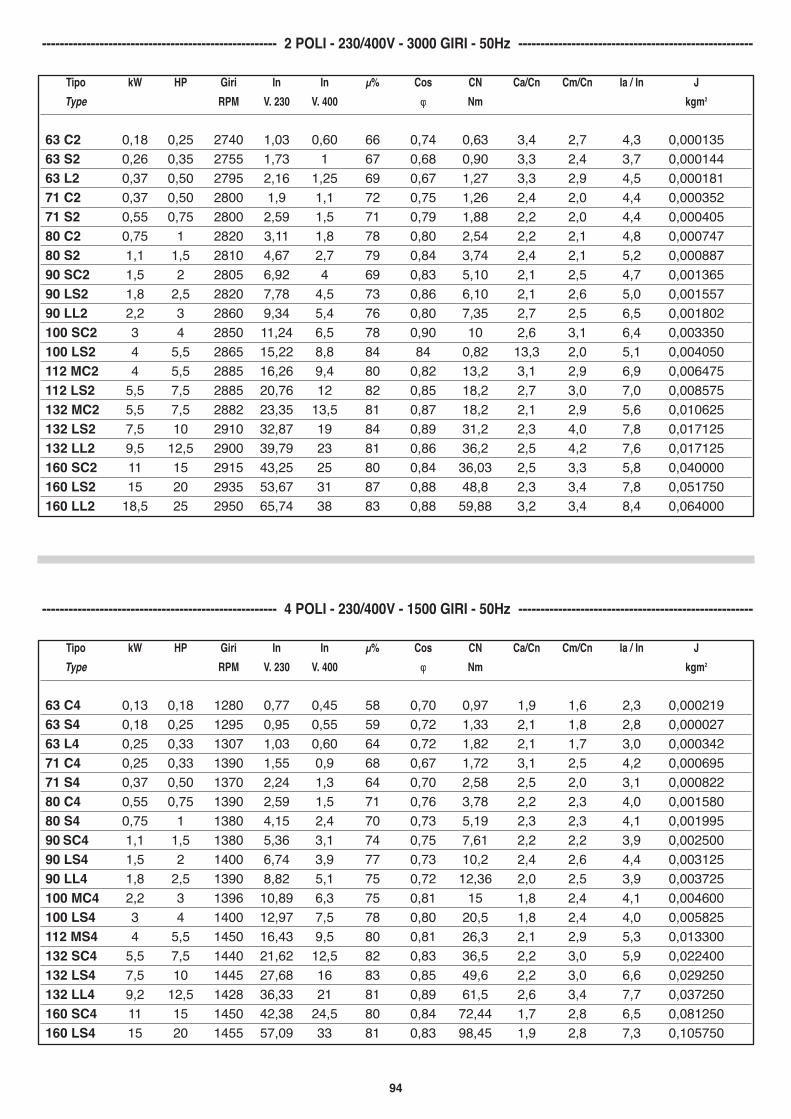
63 C4 0,13 0,18 1280 0,77 0,45 58 0,70 0,97 1,9 1,6 2,3 0,00021963 S4 0,18 0,25 1295 0,95 0,55 59 0,72 1,33 2,1 1,8 2,8 0,00002763 L4 0,25 0,33 1307 1,03 0,60 64 0,72 1,82 2,1 1,7 3,0 0,00034271 C4 0,25 0,33 1390 1,55 0,9 68 0,67 1,72 3,1 2,5 4,2 0,00069571 S4 0,37 0,50 1370 2,24 1,3 64 0,70 2,58 2,5 2,0 3,1 0,00082280 C4 0,55 0,75 1390 2,59 1,5 71 0,76 3,78 2,2 2,3 4,0 0,00158080 S4 0,75 1 1380 4,15 2,4 70 0,73 5,19 2,3 2,3 4,1 0,00199590 SC4 1,1 1,5 1380 5,36 3,1 74 0,75 7,61 2,2 2,2 3,9 0,00250090 LS4 1,5 2 1400 6,74 3,9 77 0,73 10,2 2,4 2,6 4,4 0,00312590 LL4 1,8 2,5 1390 8,82 5,1 75 0,72 12,36 2,0 2,5 3,9 0,003725100 MC4 2,2 3 1396 10,89 6,3 75 0,81 15 1,8 2,4 4,1 0,004600100 LS4 3 4 1400 12,97 7,5 78 0,80 20,5 1,8 2,4 4,0 0,005825112 MS4 4 5,5 1450 16,43 9,5 80 0,81 26,3 2,1 2,9 5,3 0,013300132 SC4 5,5 7,5 1440 21,62 12,5 82 0,83 36,5 2,2 3,0 5,9 0,022400132 LS4 7,5 10 1445 27,68 16 83 0,85 49,6 2,2 3,0 6,6 0,029250132 LL4 9,2 12,5 1428 36,33 21 81 0,89 61,5 2,6 3,4 7,7 0,037250160 SC4 11 15 1450 42,38 24,5 80 0,84 72,44 1,7 2,8 6,5 0,081250160 LS4 15 20 1455 57,09 33 81 0,83 98,45 1,9 2,8 7,3 0,105750
----------------------------------------------------- 4 POLI - 230/400V - 1500 GIRI - 50Hz -----------------------------------------------------
Tipo kW HP Giri In In µ% Cos CN Ca/Cn Cm/Cn Ia / In JType RPM V. 230 V. 400 ϕϕ Nm kgm2
63 C2 0,18 0,25 2740 1,03 0,60 66 0,74 0,63 3,4 2,7 4,3 0,00013563 S2 0,26 0,35 2755 1,73 1 67 0,68 0,90 3,3 2,4 3,7 0,00014463 L2 0,37 0,50 2795 2,16 1,25 69 0,67 1,27 3,3 2,9 4,5 0,00018171 C2 0,37 0,50 2800 1,9 1,1 72 0,75 1,26 2,4 2,0 4,4 0,00035271 S2 0,55 0,75 2800 2,59 1,5 71 0,79 1,88 2,2 2,0 4,4 0,00040580 C2 0,75 1 2820 3,11 1,8 78 0,80 2,54 2,2 2,1 4,8 0,00074780 S2 1,1 1,5 2810 4,67 2,7 79 0,84 3,74 2,4 2,1 5,2 0,00088790 SC2 1,5 2 2805 6,92 4 69 0,83 5,10 2,1 2,5 4,7 0,00136590 LS2 1,8 2,5 2820 7,78 4,5 73 0,86 6,10 2,1 2,6 5,0 0,00155790 LL2 2,2 3 2860 9,34 5,4 76 0,80 7,35 2,7 2,5 6,5 0,001802100 SC2 3 4 2850 11,24 6,5 78 0,90 10 2,6 3,1 6,4 0,003350100 LS2 4 5,5 2865 15,22 8,8 84 84 0,82 13,3 2,0 5,1 0,004050112 MC2 4 5,5 2885 16,26 9,4 80 0,82 13,2 3,1 2,9 6,9 0,006475112 LS2 5,5 7,5 2885 20,76 12 82 0,85 18,2 2,7 3,0 7,0 0,008575132 MC2 5,5 7,5 2882 23,35 13,5 81 0,87 18,2 2,1 2,9 5,6 0,010625132 LS2 7,5 10 2910 32,87 19 84 0,89 31,2 2,3 4,0 7,8 0,017125132 LL2 9,5 12,5 2900 39,79 23 81 0,86 36,2 2,5 4,2 7,6 0,017125160 SC2 11 15 2915 43,25 25 80 0,84 36,03 2,5 3,3 5,8 0,040000160 LS2 15 20 2935 53,67 31 87 0,88 48,8 2,3 3,4 7,8 0,051750160 LL2 18,5 25 2950 65,74 38 83 0,88 59,88 3,2 3,4 8,4 0,064000
----------------------------------------------------- 2 POLI - 230/400V - 3000 GIRI - 50Hz -----------------------------------------------------

95
Tipo kW HP Giri In In µ% Cos CN Ca/Cn Cm/Cn Ia / In JType RPM V. 230 V. 400 ϕϕ Nm kgm2
71 C8 0,15 0,20 605 1,25 0,72 50 0,60 2,37 1,7 1,7 1,8 0,0008280 C8 0,25 0,35 680 1,87 1,08 56 0,62 3,52 1,5 1,7 2,4 0,0019790 SC8 0,37 0,50 695 2,77 1,60 54 0,61 5,10 1,6 2 2,7 0,0031890 LS8 0,55 0,75 685 3,72 2,15 58 0,65 7,67 1,7 1,9 2,8 0,00478100 SC8 0,75 1 695 3,98 2,30 64 0,72 10,3 1,4 1,7 2,9 0,00673100 LS8 1,1 1,5 695 6,57 3,80 62 0,68 15,1 1,8 1,9 2,9 0,00925112 SC8 1,5 2 690 7,79 4,50 68 0,71 20,8 1,3 2 2,9 0,01670132 SC8 2,2 3 705 11,07 6,40 69 0,73 29,8 1,5 2 3 0,02950132 LS8 3 4 710 14,88 8,60 70 0,72 40,4 1,5 2 3,2 0,03775160 SC8 4 5,5 715 17,39 10,05 77 0,73 53,4 1,4 2,2 3 0,8950160 LS8 5,5 7,5 720 22,66 13,10 81 0,76 72,9 1,4 2,6 3,6 0,11950160 LL8 7,5 10 710 29,41 17,00 82 0,77 100,8 1,3 2,8 3,6 0,15025
----------------------------------------------------- 4 POLI - 230/400V - 1500 GIRI - 50Hz -----------------------------------------------------
Tipo kW HP Giri In In µ% Cos CN Ca/Cn Cm/Cn Ia / In JType RPM V. 230 V. 400 ϕϕ Nm kgm2
63 C6 0,09 0,12 835 0,74 0,43 52 0,62 1,03 1,4 1,3 1,9 0,0003371 C6 0,18 0,25 865 1,24 0,72 66 0,69 1,98 1,9 1,6 2,3 0,0012471 S6 0,25 0,33 875 1,49 0,86 63 0,69 2,79 1,8 2,4 2,2 0,0012480 C6 0,37 0,50 900 2,32 1,34 60 0,70 3,92 1,5 1,9 2,7 0,0019780 S6 0,55 0,75 926 3,46 2,00 63 0,64 5,67 2,1 2,3 3,3 0,0024790 SC6 0,75 1 895 3,63 2,01 66 0,78 8 1,8 1,8 3,3 0,0031890 LS6 1,1 1,5 900 5,28 3,05 70 0,75 11,7 1,7 2 3,4 0,00478100 SC6 1,5 2 925 7,09 4,11 71 0,74 15,5 1,8 2,1 3,6 0,00673100 LS6 1,8 2,5 940 9,52 5,50 68 0,72 18,3 2,1 2,3 4 0,00943112 SC6 2,2 3 910 9,80 5,70 75 0,77 23 1,4 1,8 4 0,01418112 LS6 3 4 916 11,87 6,86 75 0,82 31 1,5 2,2 4,5 0,01870132 SC6 3 4 950 13,49 7,80 71 0,77 30,1 1,3 2 3,5 0,02353132LS6 4 5,5 950 17,82 10,11 75 0,77 42 1,3 2,2 4,3 0,00295132 LL6 5,5 7,5 955 23,01 13,55 77 0,78 55 1,5 2,3 4 0,03775160SC6 7,5 10 960 27,94 16,12 80 0,83 74,6 1,2 2,4 3 0,00813160 LS6 11 15 950 41,92 24,23 80 0,83 110,57 1,2 2,5 3 0,01058
----------------------------------------------------- 6 POLI - 230/400V - 1000 GIRI - 50Hz -----------------------------------------------------
1kW = 1,34 HPgiri = velocità al min’In = corrente nominale a pieno caricoµ% = rendimentoCos fi = Fattore di potenzaJ = momento di inerzia
Cn = coppia nominaleCa/Cn = rapporto coppia avviamento/coppia nominaleCm/Cn = Rapporto coppia massima/coppia nominalela/ln = rapporto corrente di avviamento/corrente
1kW = 1,34 HPgiri = rated speedIn = rated currentµ% = efficiencyCos fi = power factorJ = moment of inertia
Cn = rated torqueCa/Cn = starting torque to rated torqueCm/Cn = maximum torque to rated torquela/ln = startin current to rated current

96
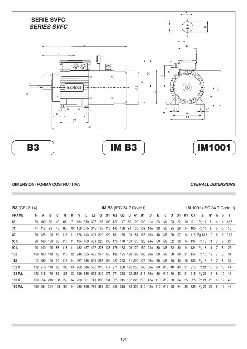
FRAME H A B C R K V L L2 G G1 G2 G3 U A1 B1 D E d63 63 100 80 40 66 7 134 300 277 167 102 127 117 80 120 100 11K6 23 M471 71 112 90 45 66 10 156 325 295 185 113 145 138 91 135 109 14K6 30 M580 80 125 100 50 115 11 176 368 328 210 129 161 155 103 154 125 19K6 40 M690 C 90 140 100 56 115 11 194 404 354 225 135 176 178 109 170 125 24K6 50 M890 L 90 140 125 56 115 11 132 432 382 225 135 176 178 109 170 150 24K6 50 M8100 100 160 140 63 115 12 246 485 425 247 146 198 195 120 192 166 28K6 60 M8112 112 190 140 70 115 14 267 525 465 267 154 222 223 131 220 175 28K6 60 M8132 C 132 216 140 89 105 13 282 608 528 310 177 271 258 122 256 180 38K6 80 M10132 M/L 132 216 178 89 105 13 399 646 566 310 177 271 258 122 256 218 38K6 80 M10160 C 160 254 210 108 150 14 230 751 641 385 234 325 315 182 320 270 42K6 110 M12160 M/L 160 254 254 108 150 14 230 796 686 385 234 325 315 182 320 310 42K6 110 M12
X X1 K1 C1 Z H1 h b t23 22 10 91 Pg 11 8 4 4 12,525 26 14 100 Pg 11 9 5 5 1629 27 14 116 Pg 13,5 10 6 6 21,532 30 14 134 Pg 16 11 7 8 2732 30 14 134 Pg 16 11 7 8 2738 36 21 154 Pg 16 12 7 8 3140 40 18 183 Pg 16 15 7 8 3140 43 21 215 Pg 21 18 8 10 4140 43 21 215 Pg 21 18 8 10 4158 64 25 325 Pg 21 23 8 12 4558 64 25 325 Pg 21 23 8 12 45
DIMENSIONI FORMA COSTRUTTIVA OVERALL DIMENSIONS
B3 IM B3 IM1001
B3 (CEI 2-14) IM B3 (IEC 34-7 Code I) IM 1001 (IEC 34-7 Code II)
SERIE SVFSERIES SVF

97
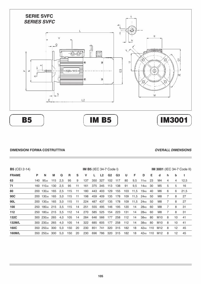
FRAME P N M Q R S V L L2 G2 G3 U F63 140 95J6 115 2,5 95 9 137 300 277 102 117 80 9,571 160 110J6 130 2,5 95 11 161 325 295 113 138 91 9,580 200 130J6 165 2,5 115 11 180 368 328 129 155 103 11,590C 200 130J6 165 3,0 115 11 198 404 354 135 178 109 11,590L 200 130J6 165 3,0 115 11 224 432 382 135 178 109 11,5100 250 180J6 215 3,5 115 14 251 485 425 146 195 120 14112 250 180J6 215 3,5 112 14 270 525 465 154 223 131 14132C 300 230J6 265 4,0 105 14 284 608 528 177 258 112 14132M/L 300 230J6 265 4,0 105 14 322 646 566 177 258 112 14160C 350 250J6 300 5,0 150 20 230 751 641 320 315 182 18160M/L 350 250J6 300 5,0 150 20 230 796 686 320 315 182 18
D E d h b t11K6 23 M4 4 4 12,514K6 30 M5 5 5 1619K6 40 M6 6 6 21,524K6 50 M8 7 8 2724K6 50 M8 7 8 2728K6 60 M8 7 8 3128K6 60 M8 7 8 3138K6 80 M10 8 10 4138K6 80 M10 8 10 4142K6 110 M12 8 12 4542K6 110 M12 8 12 45
DIMENSIONI FORMA COSTRUTTIVA OVERALL DIMENSIONS
B5 IM B5 IM3001
B5 (CEI 2-14) IM B5 (IEC 34-7 Code I) IM 3001 (IEC 34-7 Code II)
SERIE SVFSERIES SVF

98
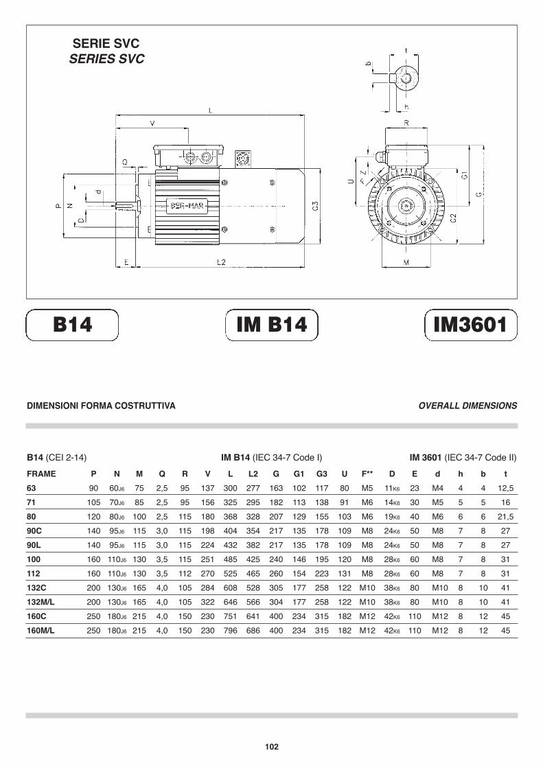
FRAME P N M Q R V L L2 G G1 G3 U F**63 90 60J6 75 2,5 95 137 300 277 163 102 117 80 M571 105 70J6 85 2,5 95 156 325 295 182 113 138 91 M680 120 80J6 100 2,5 115 180 368 328 207 129 155 103 M690C 140 95J6 115 3,0 115 198 404 354 217 135 178 109 M890L 140 95J6 115 3,0 115 224 432 382 217 135 178 109 M8100 160 110J6 130 3,5 115 251 485 425 240 146 195 120 M8112 160 110J6 130 3,5 112 270 525 465 260 154 223 131 M8132C 200 130J6 165 4,0 105 284 608 528 305 177 258 122 M10132M/L 200 130J6 165 4,0 105 322 646 566 304 177 258 122 M10160C 250 180J6 215 4,0 150 230 751 641 400 234 315 182 M12160M/L 250 180J6 215 4,0 150 230 796 686 400 234 315 182 M12
D E d h b t11K6 23 M4 4 4 12,514K6 30 M5 5 5 1619K6 40 M6 6 6 21,524K6 50 M8 7 8 2724K6 50 M8 7 8 2728K6 60 M8 7 8 3128K6 60 M8 7 8 3138K6 80 M10 8 10 4138K6 80 M10 8 10 4142K6 110 M12 8 12 4542K6 110 M12 8 12 45
DIMENSIONI FORMA COSTRUTTIVA OVERALL DIMENSIONS
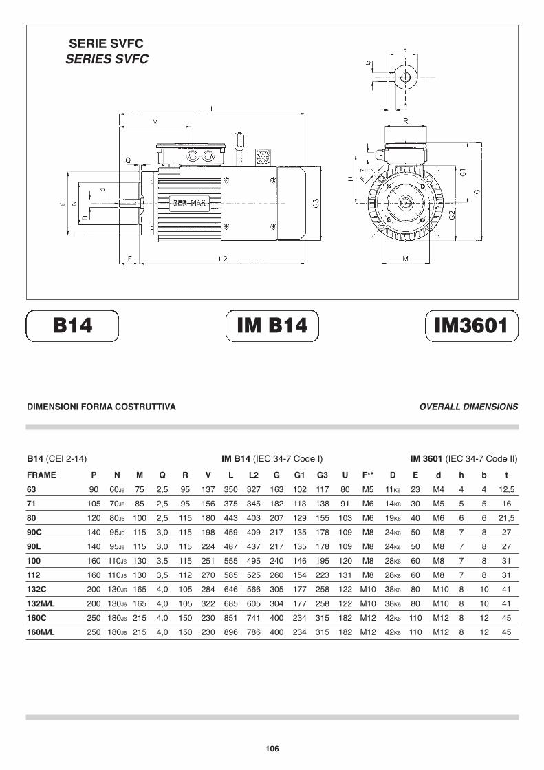
B14 IM B14 IM3601
B14 (CEI 2-14) IM B14 (IEC 34-7 Code I) IM 3601 (IEC 34-7 Code II)
SERIE SVFSERIES SVF

99
PARTI RICAMBIO MOTORI SERIE SVF
1 COPRIVENTOLA2 VITE FISSAGGIO COPRIVENTOLA3 VENTOLA ELETTRICA4 VITI FISSAGGIO VENTOLA5 SUPPORTO COPRIVENTOLA6 VITE SUPPORTO COPRIVENTOLA7 VITI FISSAGGIO FRENO8 FRENO MAGNETICO A MOLLA9 SBLOCCO MANUALE FRENO10 MOZZO FRENO11 DISCO FRENO12 SCUDO LATO FRENO13 MOLLA COMPENSATRICE14 CUSCINETTO POSTERIORE15 ANELLI SEGER16 ALBERO MOTORE17 CHIAVETTA FRENO18 ROTORE19 CHIAVETTA LATO COMANDO20 CUSCINETTO ANTERIORE21 CARCASSA MOTORE22 PERNO FISSAGGIO MOTORE23 MORSETTIERA MOTORE24 VITE FISSAGGIO MORSETTIERA25 GUARNIZIONE26 ALIMENTATORE FRENO27 SUPPORTO COPRIMORSETTIERA28 MORSETTIERA VENTILATORE
29 STATORE AVVOLTO30 SCUDO B 331 TENUTA ALBERO32 FLANGIA B 1433 FLANGIA B 534 VITI FISSAGGIO MORSETTIERA
VENTILATORE35 VITI FISSAGGIO ALIMENTATORE36 GUARNIZIONE37 COPRIMORSETTIERA38 VITE FISSAGGIO COPRIMORSETTIERA39 DADO ASSEMBLAGGIO MOTORE40 RONDELLA41 LEVA SBLOCCO MANUALE FRENO
SPARE PART’S FOR SVF MOTORS
1 COVER FAN2 COVER FAN ASSEMBLY SCREW3 ELECTRIC FAN4 ASSEMBLING FAN SCREW5 COVER FAN SUPPORT6 COVER FAN SUPPORT ASSEMBLIN SCREW7 BRAKE SCREW ASSEMBLING8 FAIL SAFE BRAKE WITH SPRING9 BRAKE HAND RELEASE10 BRAKE HUB11 BRAKE DISK12 BRAKE BELL
13 SHAFT COMPENSATION SPRING14 BEARING FAN SIDE15 RINGS16 MOTOR SHAFT17 BRAKE KEY18 MOTOR ROTOR19 DRIVE KEY20 DRIVE BEARING21 MOTOR CASE22 MOTOR SCREW ASSEMBLING23 MOTOR TERMINAL BOARD24 TERMINAL BOARD SCREW ASSEMBLING25 GASKET26 BRAKE RECTIFIER27 COVER BOX SUPPORT28 FAN TERMINAL BOARD29 WINDING30 B 3 DRIVE BELL31 SHAFT SEAL32 B 14 FLANGE33 B 5 FLANGE34 FAN TERMINAL BOARD SCREW
ASSEMBLING35 BRAKE RECTIFIER SCREW ASSEMBLING36 GASKET37 COVER BOX38 COVER BOX SCREW ASSEMBLING39 NUT MOTOR ASSEMBLING40 WASHER41 HAND RELEASE LEVER

100
FRAME H A B C R K V L L2 G G1 G2 G3 U A1 B1 D E d63 63 100 80 40 66 7 134 300 277 167 102 127 117 80 120 100 11K6 23 M471 71 112 90 45 66 10 156 325 295 185 113 145 138 91 135 109 14K6 30 M580 80 125 100 50 115 11 176 368 328 210 129 161 155 103 154 125 19K6 40 M690 C 90 140 100 56 115 11 194 404 354 225 135 176 178 109 170 125 24K6 50 M890 L 90 140 125 56 115 11 132 432 382 225 135 176 178 109 170 150 24K6 50 M8100 100 160 140 63 115 12 246 485 425 247 146 198 195 120 192 166 28K6 60 M8112 112 190 140 70 115 14 267 525 465 267 154 222 223 131 220 175 28K6 60 M8132 C 132 216 140 89 105 13 282 608 528 310 177 271 258 122 256 180 38K6 80 M10132 M/L 132 216 178 89 105 13 399 646 566 310 177 271 258 122 256 218 38K6 80 M10160 C 160 254 210 108 150 14 230 751 641 385 234 325 315 182 320 270 42K6 110 M12160 M/L 160 254 254 108 150 14 230 796 686 385 234 325 315 182 320 310 42K6 110 M12
X X1 K1 C1 Z H1 h b t23 22 10 91 Pg 11 8 4 4 12,525 26 14 100 Pg 11 9 5 5 1629 27 14 116 Pg 13,5 10 6 6 21,532 30 14 134 Pg 16 11 7 8 2732 30 14 134 Pg 16 11 7 8 2738 36 21 154 Pg 16 12 7 8 3140 40 18 183 Pg 16 15 7 8 3140 43 21 215 Pg 21 18 8 10 4140 43 21 215 Pg 21 18 8 10 4158 64 25 325 Pg 21 23 8 12 4558 64 25 325 Pg 21 23 8 12 45
DIMENSIONI FORMA COSTRUTTIVA OVERALL DIMENSIONS
B3 IM B3 IM1001
B3 (CEI 2-14) IM B3 (IEC 34-7 Code I) IM 1001 (IEC 34-7 Code II)
SERIE SVCSERIES SVC

101
FRAME P N M Q R S V L L2 G2 G3 U F63 140 95J6 115 2,5 95 9 137 300 277 102 117 80 9,571 160 110J6 130 2,5 95 11 161 325 295 113 138 91 9,580 200 130J6 165 2,5 115 11 180 368 328 129 155 103 11,590C 200 130J6 165 3,0 115 11 198 404 354 135 178 109 11,590L 200 130J6 165 3,0 115 11 224 432 382 135 178 109 11,5100 250 180J6 215 3,5 115 14 251 485 425 146 195 120 14112 250 180J6 215 3,5 112 14 270 525 465 154 223 131 14132C 300 230J6 265 4,0 105 14 284 608 528 177 258 112 14132M/L 300 230J6 265 4,0 105 14 322 646 566 177 258 112 14160C 350 250J6 300 5,0 150 20 230 751 641 320 315 182 18160M/L 350 250J6 300 5,0 150 20 230 796 686 320 315 182 18
D E d h b t11K6 23 M4 4 4 12,514K6 30 M5 5 5 1619K6 40 M6 6 6 21,524K6 50 M8 7 8 2724K6 50 M8 7 8 2728K6 60 M8 7 8 3128K6 60 M8 7 8 3138K6 80 M10 8 10 4138K6 80 M10 8 10 4142K6 110 M12 8 12 4542K6 110 M12 8 12 45
DIMENSIONI FORMA COSTRUTTIVA OVERALL DIMENSIONS
B5 IM B5 IM3001
B5 (CEI 2-14) IM B5 (IEC 34-7 Code I) IM 3001 (IEC 34-7 Code II)
SERIE SVCSERIES SVC
102
FRAME P N M Q R V L L2 G G1 G3 U F**63 90 60J6 75 2,5 95 137 300 277 163 102 117 80 M571 105 70J6 85 2,5 95 156 325 295 182 113 138 91 M680 120 80J6 100 2,5 115 180 368 328 207 129 155 103 M690C 140 95J6 115 3,0 115 198 404 354 217 135 178 109 M890L 140 95J6 115 3,0 115 224 432 382 217 135 178 109 M8100 160 110J6 130 3,5 115 251 485 425 240 146 195 120 M8112 160 110J6 130 3,5 112 270 525 465 260 154 223 131 M8132C 200 130J6 165 4,0 105 284 608 528 305 177 258 122 M10132M/L 200 130J6 165 4,0 105 322 646 566 304 177 258 122 M10160C 250 180J6 215 4,0 150 230 751 641 400 234 315 182 M12160M/L 250 180J6 215 4,0 150 230 796 686 400 234 315 182 M12
D E d h b t11K6 23 M4 4 4 12,514K6 30 M5 5 5 1619K6 40 M6 6 6 21,524K6 50 M8 7 8 2724K6 50 M8 7 8 2728K6 60 M8 7 8 3128K6 60 M8 7 8 3138K6 80 M10 8 10 4138K6 80 M10 8 10 4142K6 110 M12 8 12 4542K6 110 M12 8 12 45
DIMENSIONI FORMA COSTRUTTIVA OVERALL DIMENSIONS
B14 IM B14 IM3601
B14 (CEI 2-14) IM B14 (IEC 34-7 Code I) IM 3601 (IEC 34-7 Code II)
SERIE SVCSERIES SVC

103
PARTI RICAMBIO MOTORI SERIE SVC
1 COPRIVENTOLA2 VITE FISSAGGIO COPRIVENTOLA3 VENTOLA ELETTRICA4 VITI FISSAGGIO VENTOLA5 SUPPORTO COPRIVENTOLA5 COVER FAN SUPPORT6 VITE SUPPORTO COPRIVENTOLA7 VITI FISSAGGIO ENCODER8 ENCODER9 SUPPORTER ENCODER10 CONNETTORE ENCODER11 SUPPORTO CONNETTORE12 SCUDO POSTERIORE CON ATTACCO
ENCODER13 MOLLA COMPENSATRICE14 CUSCINETTO POSTERIORE15 VITI FISSAGGIO SUPPORTO CONNETTORE16 ALBERO MOTORE CON ATTACCO
ENCODER17 RONDELLA18 ROTORE19 CHIAVETTA LATO COMANDO20 CUSCINETTO ANTERIORE21 CARCASSA MOTORE22 PERNO FISSAGGIO MOTORE23 MORSETTIERA MOTORE
24 VITE FISSAGGIO MORSETTIERA25 GUARNIZIONE26 DADO ASSEMBLAGGIO MOTORE27 SUPPORTO COPRIMORSETTIERA28 FAN TERMINAL BOARD29 STATORE AVVOLTO30 SCUDO B 331 TENUTA ALBERO32 FLANGIA B 1433 FLANGIA B 534 VITI FISSAGGIO MORSETTIERA
VENTILATORE35 VITI FISSAGGIO COPRIMORSETTIERA36 GUARNIZIONE37 COPRIMORSETTIERA
SPARE PART’S FOR SVC MOTORS
1 COVER FAN2 COVER FAN ASSEMBLY SCREW3 ELECTRIC FAN4 ASSEMBLING FAN SCREW6 COVER FAN SUPPORT ASSEMBLIN SCREW7 ENCODER SCREW ASSEMBLING8 ENCODER9 ENCODER SUPPORT10 ENCODER PLUG
11 PLUG SUPPORT12 END BELL WITH ENCODER JUNCTION13 SHAFT COMPENSATION SPRING14 BEARING FAN SIDE15 PLUG SUPPORT SCREW ASSEMBLING16 MOTOR SHAFT WITH ENCODER JUNCTION17 WASHER18 MOTOR ROTOR19 DRIVE KEY20 DRIVE BEARING21 MOTOR CASE22 MOTOR SCREW ASSEMBLING23 MOTOR TERMINAL BOARD24 TERMINAL BOARD SCREW ASSEMBLING25 GASKET26 NUT MOTOR ASSEMBLING27 COVER BOX SUPPORT28 MORSETTIERA VENTILATORE29 WINDING WITH STATOR30 B 3 DRIVE BELL31 SHAFT SEAL32 B 14 FLANGE33 B 5 FLANGE34 FAN TERMINAL BOARD SCREW
ASSEMBLING35 COVER BOX SCREW ASSEMBLING36 GASKET37 COVER BOX
104
FRAME H A B C R K V L L2 G G1 G2 G3 U A1 B1 D E d63 63 100 80 40 66 7 134 350 327 167 102 127 117 80 120 100 11K6 23 M471 71 112 90 45 66 10 156 375 345 185 113 145 138 91 135 109 14K6 30 M580 80 125 100 50 115 11 176 443 403 210 129 161 155 103 154 125 19K6 40 M690 C 90 140 100 56 115 11 194 459 409 225 135 176 178 109 170 125 24K6 50 M890 L 90 140 125 56 115 11 132 487 437 225 135 176 178 109 170 150 24K6 50 M8100 100 160 140 63 115 12 246 555 495 247 146 198 195 120 192 166 28K6 60 M8112 112 190 140 70 115 14 267 585 525 267 154 222 223 131 220 175 28K6 60 M8132 C 132 216 140 89 105 13 282 646 566 310 177 271 258 122 256 180 38K6 80 M10132 M/L 132 216 178 89 105 13 399 685 605 310 177 271 258 122 256 218 38K6 80 M10160 C 160 254 210 108 150 14 230 851 741 385 234 325 315 182 320 270 42K6 110 M12160 M/L 160 254 254 108 150 14 230 896 786 385 234 325 315 182 320 310 42K6 110 M12
X X1 K1 C1 Z H1 h b t23 22 10 91 Pg 11 8 4 4 12,525 26 14 100 Pg 11 9 5 5 1629 27 14 116 Pg 13,5 10 6 6 21,532 30 14 134 Pg 16 11 7 8 2732 30 14 134 Pg 16 11 7 8 2738 36 21 154 Pg 16 12 7 8 3140 40 18 183 Pg 16 15 7 8 3140 43 21 215 Pg 21 18 8 10 4140 43 21 215 Pg 21 18 8 10 4158 64 25 325 Pg 21 23 8 12 4558 64 25 325 Pg 21 23 8 12 45
DIMENSIONI FORMA COSTRUTTIVA OVERALL DIMENSIONS
B3 IM B3 IM1001
B3 (CEI 2-14) IM B3 (IEC 34-7 Code I) IM 1001 (IEC 34-7 Code II)
SERIE SVFCSERIES SVFC
105
FRAME P N M Q R S V L L2 G2 G3 U F63 140 95J6 115 2,5 95 9 137 350 327 102 117 80 9,571 160 110J6 130 2,5 95 11 161 375 345 113 138 91 9,580 200 130J6 165 2,5 115 11 180 443 403 129 155 103 11,590C 200 130J6 165 3,0 115 11 198 459 409 135 178 109 11,590L 200 130J6 165 3,0 115 11 224 487 437 135 178 109 11,5100 250 180J6 215 3,5 115 14 251 555 495 146 195 120 14112 250 180J6 215 3,5 112 14 270 585 525 154 223 131 14132C 300 230J6 265 4,0 105 14 284 646 566 177 258 112 14132M/L 300 230J6 265 4,0 105 14 322 685 605 177 258 112 14160C 350 250J6 300 5,0 150 20 230 851 741 320 315 182 18160M/L 350 250J6 300 5,0 150 20 230 696 786 320 315 182 18
D E d h b t11K6 23 M4 4 4 12,514K6 30 M5 5 5 1619K6 40 M6 6 6 21,524K6 50 M8 7 8 2724K6 50 M8 7 8 2728K6 60 M8 7 8 3128K6 60 M8 7 8 3138K6 80 M10 8 10 4138K6 80 M10 8 10 4142K6 110 M12 8 12 4542K6 110 M12 8 12 45
DIMENSIONI FORMA COSTRUTTIVA OVERALL DIMENSIONS
B5 IM B5 IM3001
B5 (CEI 2-14) IM B5 (IEC 34-7 Code I) IM 3001 (IEC 34-7 Code II)
SERIE SVFCSERIES SVFC
106
FRAME P N M Q R V L L2 G G1 G3 U F**63 90 60J6 75 2,5 95 137 350 327 163 102 117 80 M571 105 70J6 85 2,5 95 156 375 345 182 113 138 91 M680 120 80J6 100 2,5 115 180 443 403 207 129 155 103 M690C 140 95J6 115 3,0 115 198 459 409 217 135 178 109 M890L 140 95J6 115 3,0 115 224 487 437 217 135 178 109 M8100 160 110J6 130 3,5 115 251 555 495 240 146 195 120 M8112 160 110J6 130 3,5 112 270 585 525 260 154 223 131 M8132C 200 130J6 165 4,0 105 284 646 566 305 177 258 122 M10132M/L 200 130J6 165 4,0 105 322 685 605 304 177 258 122 M10160C 250 180J6 215 4,0 150 230 851 741 400 234 315 182 M12160M/L 250 180J6 215 4,0 150 230 896 786 400 234 315 182 M12
D E d h b t11K6 23 M4 4 4 12,514K6 30 M5 5 5 1619K6 40 M6 6 6 21,524K6 50 M8 7 8 2724K6 50 M8 7 8 2728K6 60 M8 7 8 3128K6 60 M8 7 8 3138K6 80 M10 8 10 4138K6 80 M10 8 10 4142K6 110 M12 8 12 4542K6 110 M12 8 12 45
DIMENSIONI FORMA COSTRUTTIVA OVERALL DIMENSIONS
B14 IM B14 IM3601
B14 (CEI 2-14) IM B14 (IEC 34-7 Code I) IM 3601 (IEC 34-7 Code II)
SERIE SVFCSERIES SVFC

107
PARTI RICAMBIO MOTORI SERIE SVFC
1 COPRIVENTOLA2 VITE FISSAGGIO COPRIVENTOLA3 VENTOLA ELETTRICA4 VITI FISSAGGIO VENTOLA5 SUPPORTO COPRIVENTOLA6 VITE SUPPORTO COPRIVENTOLA7 VITI FISSAGGIO FRENO8 FRENO MAGNETICO A MOLLA9 SBLOCCO MANUALE FRENO10 MOZZO FRENO11 DISCO FRENO12 SCUDO LATO FRENO13 MOLLA COMPENSATRICE14 CUSCINETTO POSTERIORE15 ANELLI SEGER16 ALBERO MOTORE17 CHIAVETTA FRENO18 ROTORE19 CHIAVETTA LATO COMANDO20 CUSCINETTO ANTERIORE21 CARCASSA MOTORE22 PERNO FISSAGGIO MOTORE23 MORSETTIERA MOTORE24 VITE FISSAGGIO MORSETTIERA25 GUARNIZIONE26 ALIMENTATORE FRENO27 SUPPORTO COPRIMORSETTIERA28 MORSETTIERA VENTILATORE29 STATORE AVVOLTO30 SCUDO B 331 TENUTA ALBERO
32 FLANGIA B 1433 FLANGIA B 534 VITI FISSAGGIO MORSETTIERA VENTILATORE35 VITI FISSAGGIO ALIMENTATORE36 GUARNIZIONE37 COPRIMORSETTIERA38 VITE FISSAGGIO COPRIMORSETTIERA39 DADO ASSEMBLAGGIO MOTORE40 RONDELLA41 VITI FISSAGGIO SUPPORTO CONNETTORE42 SUPPORTO CONNETTORE43 CONNETTORE44 VITI FISSAGGIO ENCODER45 ENCODER46 SUPPORTO ENCODER47 LEVA SBLOCCO MANUALE FRENO
SPARE PART’S FOR SVFC MOTORS
1 COVER FAN2 COVER FAN ASSEMBLY SCREW3 ELECTRIC FAN4 ASSEMBLING FAN SCREW5 COVER FAN SUPPORT6 COVER FAN SUPPORT ASSEMBLING SCREW7 BRAKE SCREW ASSEMBLING8 FAIL SAFE BRAKE WITH SPRING9 BRAKE HAND RELEASE10 BRAKE HUB11 BRAKE DISK12 BRAKE BELL13 SHAFT COMPENSATION SPRING14 BEARING FAN SIDE
15 RINGS16 MOTOR SHAFT17 BRAKE KEY18 MOTOR ROTOR19 DRIVE KEY20 DRIVE BEARING21 MOTOR CASE22 MOTOR SCREW ASSEMBLING23 MOTOR TERMINAL BOARD24 TERMINAL BOARD SCREW ASSEMBLING25 GASKET26 BRAKE RECTIFIER27 COVER BOX SUPPORT28 FAN TERMINAL BOARD29 WINDING30 B 3 DRIVE BELL31 SHAFT SEAL32 B 14 FLANGE33 B 5 FLANGE34 FAN TERMINAL BOARD SCREW ASSEMBLING35 BRAKE RECTIFIER SCREW ASSEMBLING36 GASKET37 COVER BOX38 COVER BOX SCREW ASSEMBLING39 NUT MOTOR ASSEMBLING40 WASHER41 PLUG SUPPORT SCREW ASSEMBLING42 PLUG SUPPORT43 ENCODER PLUG44 ENCODER SCREW ASSEMBLING45 ENCODER46 ENCODER SUPPORT47 HAND RELEASE LEVER

108
1
Ua2
- 2
Pink Rosa
Blue Azzurro
Red Rosso
Black Nero
Brown Marrone
Green Verde
Violet Viola
Gray Grigio
3
Ua0
+ 0
4
Ua0
- 0
5
Ua1
+ 1
6
Ua1
- 1
8
Ua2
+ 2
10
0 V
0 V
12
+5 V
+5 V
9
SHIELD SCHERMO
2
sensor 5 V not
connected
11
sensor 0 V not
connected
7
not connected
not connected
1 3
0
Ua0
4 5
1
A
6 8
2
B
1110
0 V
0 V
12
+10-30 V
24 V
9
SHIELD SCHERMO
2 7
Gray Grigio
Violet Viola
Yellow Giallo
White Bianco
Brown Marrone
Orange Arancio
Pink Rosa
Blue Blu
Green Verde
White Bianco
Red Rosso
Black Nero
H
S
H
S
White/Green Bianco/Verde
Brown/Green Marron/Verde
Uscita per segnali sinusoidali con amplificazione del segnaleUs = 5 V ± 20 % KUs = 10 … 30 V L
Driver di uscita per segnali ad onda quadra 5
Us = 10 … 30 V a prova di corto circuitoPush-pull (costruzione a transistori) resistente alle sovratensionimassimo 70 mA per ogni canale protetto contro le
inversioni di polaritàAdatto solo fino a 200 kHz
Driver di uscita per segnali ad onda quadra F
Us * 5 V ± 20% Us * 5 V ± 10%(versione da 300 kHz) (versione da 600 kHz)Driver di linea secondo EIA 485 A
Contiene il driver con la definizione delle interconnessioni EIA 422 A
Driver di uscita per segnali ad onda quadra GUs * 10 - 30 VUd * 5 V secondo EIA 485 A
Contiene il driver con la definizione delle interconnessioni EIA 422 A
H = HEIDENHAIN SIGNAL S = STEGMANN SIGNAL SYSTEM
CONNETTORE MOTOREPRESA VOLANTE
TTL (LINE - DRIVER) ENCODER CONNECTION
HEIDENHAIN CABLE COLORS
STEGMANN CABLE COLORS
HTL (PUSH - PULL) ENCODER CONNECTION
SEGNALI ENCODER / ENCODER SIGNALS

109

110
NOTE
111
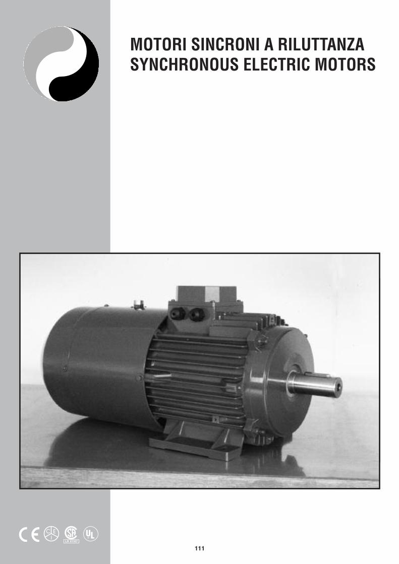
MOTORI SINCRONI A RILUTTANZASYNCHRONOUS ELECTRIC MOTORS
LR 91167®

112
Pregio di questa gamma è la totale assenza di manuten-zione che unita al vasto campo di regolazione con Inverterrendono queste macchine insostituibili per varie applica-zioni. I motori sincroni a riluttanza sono impiegati princi-palmente nell’industria tessile, in quella del vetro, nel set-tore delle materie plastiche e in tutte quelle applicazioniche necessitano di una velocità costante di uno o piùmotori anche se sollecitati con carichi differenti.
FUNZIONAMENTO
Il motore a riluttanza variabile si avvia come un normalemotore Asincrono fino a raggiungere valori molto prossimialla velocità di sincronismo. A questo punto il rotore, per lapropria disomogeneità magnetica, è soggetto a una cop-pia sincronizzante che lo porta in passo con il campomagnetico. Raggiunto il sincronismo il rotore ruota rigida-mente a questa velocità, essendo collegato direttamenteal rapporto tensione frequenza qualunque sia il caricoapplicato purchè inferiore alla coppia massima. Per cari-chi superiori, il motore perde il passo e continua a ruotarecon un certo scorrimento producendo un caratteristicorumore. In questo caso è sufficiente ridurre il carico appli-cato per riportarlo in passo. Normalmente i motoriSincroni a riluttanza possono venire avviati alimentandolidirettamente oppure a tensione ridotta. In ogni caso pergarantire l’entrata in passo è necessario fare attenzione alcarico e al momento d’inerzia applicato. Per ottenere ilfunzionamento a velocità variabile i motori della serie “SS”vengono alimentati da Inverter con frequenza variabilefino a 200 Hz. Normalmente il motore viene fatto lavorarea coppia costante pertanto la tensione deve venire variataproporzionalmente alla frequenza. Tuttavia a bassi giri ènecessaria una sovratensione di alimentazione al fine dimantenere la coppia costante e ne deriva che la potenzaresa dal motore e la corrente assorbita sono proporzionalialla frequenza. Alle alte velocità invece il funzionamento èa potenza e corrente costante, il motore è alimentato atensione anch’essa costante mentre varia la frequenza. Inquesto modo si ottiene una coppia inversamente propor-zionale alla velocità.
CARATTERISTICHE COSTRUTTIVE
I motori della serie” SS” sono del tipo chiuso a ventilazio-ne esterna e presentano dimensioni della serie unificataUNEL-MEC. Lo statore è costruito con uno specialeavvolgimento, mentre sul rotore sono state realizzatedelle riluttanze trasversali e longitudinali diverse alloscopo di ottenere la marcia sincrona. I motori di questaserie sono costruiti nelle versioni 4 e 6 poli. Le potenzenominali sono indicate in tabella e riferite alla frequenza di50 Hz per servizio continuo e alla temperatura ambientedi 40°C. Qualora si presentassero particolari esigenze eprestazioni differenti da quelle da noi indicate possonoessere forniti motori in esecuzione personalizzata.
The main characteristic of this range consists in the totalabsence of maintenance, which, together with the widetuning range by means of Inverters, makes these machi-nes irreplaceable for several applications. The reclutancesynchronous motors are used mainly in the textile indu-stry, in the glass industry, in the field of plastic materialsand in all thouse applications requiring a constant speedof one or more motors even if they are stressed with diffe-rent loads.
OPERATION
The variable reclutance motor starts as an ordinary induc-tion motor until it reaches values which are very near tothe synchronous speed. At this point rotor, due to its ownmagnetic non-homogeneity,is subject to a synchronizingtorque which makes it keep in step with the magnetic field.Once it is in step, the rotor turns exactly at this speed,being directly dependent on the voltage/frequency ratio,whatever the applied load may be, provided that it is lowerthan the max torque. For bigger loads, the motor is out ofstep and keeps turning with a certain slipping by produ-cing a characteristic noise. In this case it is enought toreduce the applied load to make it running in step again.Usually you may start the reluctance synchronous motorsby feeding them directly at a reduced voltage. In anycase, in order to be sure that motor is in step it is neces-sary to pay attention to the applied load and moment ofinertia. In order to achieve its running at variable speed,the “SS” series motors are fed by an inverter with a varia-ble frequency up to 200 Hz. Usually the motor runs at aconstant torque and therefore the voltage must be variedproportionally to the frequency. However, at a low numberof revolution a supply overvoltage is necessary in order tokeep the torque constat and therefore the power, which isgiven by the motor, and the absorber current are propor-tional to the frequency. At high speeds, instead, the run-ning is at constant power and current, the motor is fed bya constant voltage, while the frequency varies. In this waya torque inversely proportional to the speed is obtained.
LEADING PARTICULARS
The “SS” series motors are enclosed motors with an outsi-de ventilation and have same dimensions of the standar-dized UNEL-MEC series. The stator consists of specialwinding, while on the rotor there are some different tran-sversal and longitudinal reluctances in order to obtain thesynchronous running. The motors of this series are manu-factured in the 4 and 6 pole models. The rated outputs arelisted in the tables and refer to the 50 Hz frequency forcontinuous duty and to the room temperature of 40°C. Incase you have particular needs and require performancesdifferent from those here below listed, custom-mademotors may be supplied on request.
MOTORI SINCRONI A RILUTTANZARELUCTANCE SYNCRONOUS MOTORS

113
Dal diagramma sopra esposto si ricava che, effettuandouna regolazione proporzionale tensione frequenza dazero fino a quella nominale del motore, questo funziona acoppia costante con velocità e potenza proporzionali allafrequenza. Osservando l’andamento della coppia si notauna diminuzione della stessa a bassi giri. Questo feno-mento si verifica a basse frequenze perchè si riduce lareattanza rotorica, mentre aumenta la caduta di tensioneprimaria; ne consegue una diminuzione del flusso e dellacoppia. Pertanto volendo mantenere la coppia a valoriaccettabili è necessario alimentare il motore con una ten-sione più elevata. Nel caso di frequenze superiori a quellanominale non é possibile aumentare ulteriormente la ten-sione perchè le perdite nel ferro aumenterebbero in modointollerabile. Di conseguenza all’aumentare della frequen-za con tensione costante si ha una riduzione del flussomagnetico e pertanto della coppia: il motore in questocaso funziona a velocità variabile e potenza costante. Vainoltre osservato che a basse velocità il motore lavora ingravose condizioni termiche essendo ridotto notevolmentel’effetto autoventilante. Si consiglia pertanto un serviziointermittente o limitato oppure una ventilazione assistitanel caso di un servizio continuo. Ventilazione assistita checonsigliamo anche nel caso di funzionamento alle altevelocità poichè in questa situazione la ventilazione neces-saria assorbe un apotenza pari al cubo della velocità stes-sa il che potrebbe ridurre il rendimento del motore stesso.
From the above diagram it results that, by carring out aproportional regulation between frequency and voltagestarting from zero until the rated frequency of the motor,this runs at constant torque with speed and power propor-tional to the frequency. By observing the trend of the tor-que you may notice a decrease of the same one at a lownumber of revolutions. This phenomena occurs at low fre-quencies, because the rotor reactance is reduced, whilethe primary voltage drop increase; this causes a decreaseof the flux and of the torque. Therefore in order to keepthe torque at acceptable values, it is necessary to feed themotor with a higher voltage. In case of frequencies higherthan the rated frequency, it is not possible to furtherincrease the voltage because the iron losses wouldincrease too much. Therefore as the frequency increasewith constant voltage, the magnetic flux decrease and the-refore also the torque decreases; in this case the motorruns at variable speed and at constant power. You shouldnotice, moreover, that at low speeds the motor runs undersevere thermal conditions due to the fact that the selfven-tilating effect is considerably reduced. We suggest the-refore either an intermittent or limited duty or an assistedventilation in case of a continuous duty. We suggest anassisted ventilation also in case of running at high speedsbecause in this situation the necessary ventilation absorbsa power equal to the cube of the speed itself, and thiscould reduce the yield of the motor considerably.
DIAGRAMMI CARATTERISTICI DI FUNZIONAMENTO DEI MOTORI SINCRONI ARCHARACTERISTIC OPERATION DIAGRAMS OF THE “ AR” SYNCHRONOUS MOTORS
Coppia in servizio continuocon ventilazione forzatao con servizio intermittente del motore
Torque in continuos dutywith intermittent dutyoff the motor
114
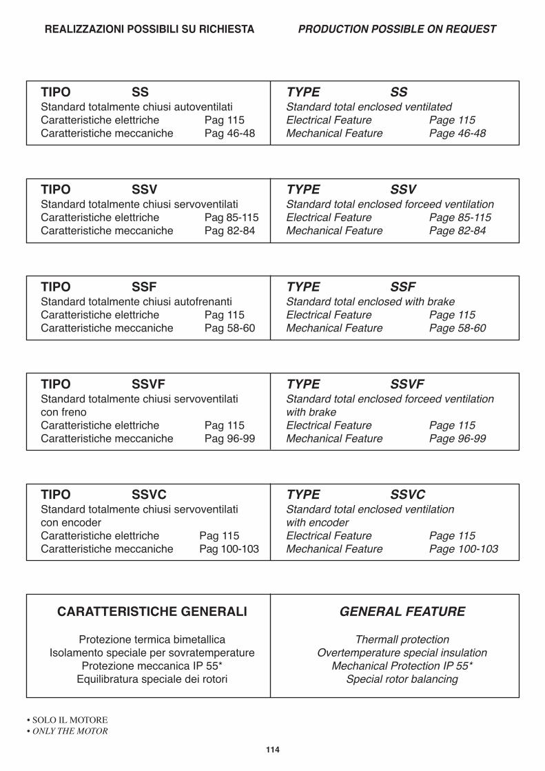
REALIZZAZIONI POSSIBILI SU RICHIESTA PRODUCTION POSSIBLE ON REQUEST
TIPO SSStandard totalmente chiusi autoventilatiCaratteristiche elettriche Pag 115Caratteristiche meccaniche Pag 46-48
TYPE SSStandard total enclosed ventilatedElectrical Feature Page 115Mechanical Feature Page 46-48
TIPO SSVStandard totalmente chiusi servoventilatiCaratteristiche elettriche Pag 85-115Caratteristiche meccaniche Pag 82-84
TYPE SSVStandard total enclosed forceed ventilationElectrical Feature Page 85-115Mechanical Feature Page 82-84
TIPO SSFStandard totalmente chiusi autofrenantiCaratteristiche elettriche Pag 115Caratteristiche meccaniche Pag 58-60
TYPE SSFStandard total enclosed with brakeElectrical Feature Page 115Mechanical Feature Page 58-60
TIPO SSVFStandard totalmente chiusi servoventilaticon frenoCaratteristiche elettriche Pag 115Caratteristiche meccaniche Pag 96-99
TYPE SSVFStandard total enclosed forceed ventilationwith brakeElectrical Feature Page 115Mechanical Feature Page 96-99
TIPO SSVCStandard totalmente chiusi servoventilaticon encoderCaratteristiche elettriche Pag 115Caratteristiche meccaniche Pag 100-103
TYPE SSVCStandard total enclosed ventilationwith encoderElectrical Feature Page 115Mechanical Feature Page 100-103
CARATTERISTICHE GENERALI
Protezione termica bimetallicaIsolamento speciale per sovratemperature
Protezione meccanica IP 55*Equilibratura speciale dei rotori
GENERAL FEATURE
Thermall protectionOvertemperature special insulation
Mechanical Protection IP 55*Special rotor balancing
• SOLO IL MOTORE• ONLY THE MOTOR

115
TIPO POTENZA VELOCITÀ COPPIA PD2 TENSIONE FREQUENZA CORRENTE PESOkW Giri/min da Nm kg m2 Volt Hz Amper kg
TYPE POWER SPEED TORQUE PD2 VOLTAGE FREQUENCY CURRENT WEIGHTkW RPM da Nm kg m2 Volt Hz Amper kg
SS 63 B 0.075 1500 0.048 0.0014 400 50 0.45 7.2
SS 71 B 0.15 1500 0.095 0.0033 400 50 0.9 10
SS 80 A 0.22 1500 0.140 0.0054 400 50 1.2 14.3
SS 80 B 0.37 1500 0.235 0.0069 400 50 1.6 16
SS 90 S 0.55 1500 0.350 0.011 400 50 2.3 19
SS 90 L 0.75 1500 0.480 0.014 400 50 3.0 22
SS 100 LA 1.1 1500 0.700 0.037 400 50 4.3 31
SS 100 LB 1.5 1500 0.955 0.048 400 50 5.2 35
SS 112 M 2.2 1500 1.400 0.075 400 50 6.8 46
SS 132 S 3 1500 1.910 0.11 400 50 9.5 67
SS 132 M 3.7 1500 2.360 0.13 400 50 11.5 76
SS 160 M 4 1500 2.550 0.24 400 50 12.8 120
SS 160 L 5.5 1500 3.500 0.3 400 50 16.0 140
SS 180 M 7.5 1500 4.780 0.64 400 50 22.5 190
SS 180 L 11 1500 7.000 0.77 400 50 33.0 217
TIPO POTENZA VELOCITÀ COPPIA PD2 TENSIONE FREQUENZA CORRENTE PESOkW Giri/min da Nm kg m2 Volt Hz Amper kg
TYPE POWER SPEED TORQUE PD2 VOLTAGE FREQUENCY CURRENT WEIGHTkW RPM da Nm kg m2 Volt Hz Amper kg
SS 80 A 0.11 1000 0.11 0.009 400 50 0.8 13.5
SS 90 S 0.37 1000 0.37 0.019 400 50 2.0 14
SS 90 L 0.55 1000 0.55 0.025 400 50 2.6 23
SS 100 L 0.75 1000 0.75 0.044 400 50 3.0 30
SS 112 M 1.1 1000 1.1 0.085 400 50 4.4 41
SS 132 S 1.5 1000 1.5 0.11 400 50 6.0 58
SS 132 MA 2.2 1000 2.2 0.16 400 50 9.0 70
SS 132 MB 3 1000 3 0.20 400 50 12.0 79
SS 160 M 3.7 1000 3.7 0.35 400 50 15.0 115
SS 160 L 4 1000 4 0.44 400 50 17.0 140
SS 180 M 5.5 1000 5.5 1.03 400 50 23.5 190
SS 180 L 7.5 1000 7.5 1.03 400 50 32.0 210
TABELLA CARATTERISTICHE NOMINALI DI FUNZIONAMENTOTABLE OF THE RATED OPERATING FEATURES
----------------------------------------- 4 POLE SERIES -----------------------------------------
----------------------------------------- 6 POLE SERIES -----------------------------------------