motor vehicle engineering
TRANSCRIPT
A Practical Approach toMotor Vehicle Engineeringand Maintenance

This page intentionally left blank
A Practical Approach toMotor Vehicle Engineeringand Maintenance
Third Edition
Allan Bonnick
Derek Newbold
AMSTERDAM � BOSTON � HEIDELBERG � LONDON � NEW YORK � OXFORD
PARIS � SAN DIEGO � SAN FRANCISCO � SINGAPORE � SYDNEY � TOKYO
Butterworth-Heinemann is an imprint of Elsevier

Butterworth-Heinemann is an imprint of Elsevier
The Boulevard, Langford Lane, Kidlington, Oxford, OX5 1GB, UK
225 Wyman Street, Waltham, MA 02451, USA
First published by Arnold 2000
Reprinted 2002, 2003, 2004
Second edition 2005
Third edition 2011
Copyright � 2011 Allan Bonnick and Derek Newbold. Published by Elsevier Ltd. All rights reserved
The rights of Allan Bonnick and Derek Newbold to be identified as the authors’ of this work has been asserted in accordance with the Copyright,
Designs and Patents Act 1988
No part of this publication may be reproduced or transmitted in any form or by any means, electronic or mechanical, including photocopying,
recording, or any information storage and retrieval system, without permission in writing from the publisher. Details on how to seek permission,
further information about the Publisher’s permissions policies and our arrangement with organizations such as the Copyright Clearance Center and
the Copyright Licensing Agency, can be found at our website: www.elsevier.com/permissions
This book and the individual contributions contained in it are protected under copyright by the Publisher (other than as may be noted herein).
Notices
Knowledge and best practice in this field are constantly changing. As new research and experience broaden our understanding, changes in
research methods, professional practices, or medical treatment may become necessary.
Practitioners and researchers must always rely on their own experience and knowledge in evaluating and using any information, methods,
compounds, or experiments described herein. In using such information or methods they should be mindful of their own safety and the safety of
others, including parties for whom they have a professional responsibility.
To the fullest extent of the law, neither the Publisher nor the authors, contributors, or editors, assume any liability for any injury and/or damage
to persons or property as a matter of products liability, negligence or otherwise, or from any use or operation of any methods, products, instructions,
or ideas contained in the material herein.
British Library Cataloguing in Publication Data
A catalogue record for this book is available from the British Library
Library of Congress Control Number: 2011924728
ISBN: 978-0-08-096998-5
For information on all Butterworth-Heinemann publications
visit our website at www.elsevierdirect.com
Printed and bound in the UK
11 12 13 14 10 9 8 7 6 5 4 3 2 1
Contents
Foreword xiii
Acknowledgements xiv
Introduction to the retail motor industry and Health and Safety at Work xv
1 Vehicle layouts and some simple vehicle structures 1
Light vehicles 1Vehicle structure 1Passenger protection 1Vehicle shape 4End-of-Life Vehicles Directive 4Layout of engine and driveline 5Self-assessment questions 7
2 Engine principles 8
Engine details 8The four-stroke Otto cycle 8The two-stroke cycle 14Two-stroke engine with valves 15Rotary engines 16The Atkinson engine cycle 16Self-assessment questions 17
3 The main moving parts of an engine 19
Valves 19Cam and follower 19Valve springs 20Valve operating mechanisms 22The camshaft drive 23Pistons 25The crankshaft and flywheel assembly 30The connecting rod 30Self-assessment questions 32
4 Multi-cylinder engines 37
Cylinder arrangements 37Engine structure e the main fixed parts 37Self-assessment questions 46
5 Firing orders and engine balance 47
Firing orders 47Crankshaft layout 47Vibrations and engine balance 48Self-assessment questions 53
6 Crankshaft, camshaft, and valve operating mechanisms 54
Crankshaft 54Camshaft 58Self-assessment questions 62
7 A petrol fuel system 67
The fuel tank 67Pump details 68Fuel return 69Mechanical fuel pump 69Pipes 69Filters 70Carbon canister 70Inertia switch 70Working with petrol 70Maintenance and repair 71Self-assessment questions 72
8 Motor fuels 74
Fuels 74Factors affecting exhaust emissions 75Emissions and their causes 76Methods of controlling exhaust emissions 77Self-assessment questions 80
9 Carburettors 81
The simple carburettor 81Rich or weak mixture 82Keeping the mixture strength constant 82Constant-choke carburettor 82Cold starts, idling, progression, and acceleration 83Constant-vacuum carburettor 84Self-assessment questions 85
10 Petrol injection e introduction 87
Petrol injection systems 87Types of petrol injection system 89Single-point injection 89Multi-point injection 91Direct petrol injection 96Fuel system maintenance and repair 97Self-assessment questions 100
11 Air supply and exhaust systems 101
Engine air supply systems (carburettor) 101Fuel-injected engine air intake system 103Variable-length induction tract 104Turbocharging 105Practical assignment e air supply and exhaust systems 107Self-assessment questions 108
vi Contents
12 Lubricants and engine lubrication 110
Lubricants 110Boundary lubrication 111Hydrodynamic lubrication 111Sources of oil 111Types of oil 112Handling oil and disposal of waste 113Lubrication system 113Self-assessment questions 122
13 Cooling systems 126
Overheating 126Heat transfer 127Over-cooling 127Types of cooling systems 128Engine air-cooling system 128Liquid cooling 130Comparison of air- and water-cooled systems 131Radiator and heater matrix 132Water pump 134Thermostat 135Pressurized cooling systems 136Fans and their operations 138Corrosion in the cooling system 142Antifreeze 142Engine temperature gauge 143Engine core plugs 144Servicing and maintaining the cooling system 145Heating and ventilation 149Interior heating and air-conditioning 149Heat losses 153Practical assignment e cooling systems 154Practical assignment e liquid cooling systems 155Self-assessment questions 156
14 Internal combustion engines 158
Engine power 158Dynamometers for high-speed engines 158Self-assessment questions 167
15 The compression ignition engine e diesel engine 168
The four-stroke compression ignition engine 168The Diesel cycle and the dual combustion cycle 168The two-stroke CIE 170Diesel engine construction 170Turbulence 171Combustion in a compression ignition engine 173Diesel fuel and products of combustion 174Emissions limits 174Emissions control on the CIE 174Self-assessment questions 176
Contents vii
16 Diesel fuel systems 177
Diesel fuel systems 177Common rail diesel fuel system 189Self-assessment questions 193
17 Engine fault diagnosis 198
Engine faults 198Mechanical condition 198Summary 204Self-assessment questions 205
18 Transmission 208
The clutch 208Operating mechanisms 211Matching the engine to the road-going needs of the vehicle 213A basic gearbox 214The constant mesh and synchromesh gearbox 215Overdrive 219Transmitting the power to the driving wheels 219Propeller shafts and drive shafts 225Constant-velocity universal joints 225Axles and axle casings 227Final drive 227Differential 228Rear hub bearing and axle shaft arrangements 229Types of bearings used in the transmission system 231Practical assignment e removing a clutch 235Practical assignment e removing and refitting a gearbox 235Practical assignment e axles and final drives 235Self-assessment questions 236
19 Electronically controlled automatic transmission 237
Fluid couplings 237Automatic gearbox 239Maintenance and fault tracing 243Self-assessment questions 246
20 Suspension systems 248
Unsprung mass 248Non-independent suspension systems 248Independent suspension 250Suspension dampers 257Maintenance checks 260Practical assignment e suspension system 260Self-assessment questions 261
21 Braking systems 263
Vehicle braking systems 263Types of brakes 263Hydraulic operation of brakes 264
viii Contents
Wheel cylinders 265The handbrake 265Split braking systems 265The tandem master cylinder 266The brake fluid reservoir 267Brake pipes and hoses 267The brake servo 267Brake adjustment 269Wear indicators 270Stop lamp switch 270Brake pressure control valve 270Brake fluid 271Braking efficiency 271Anti-lock braking system (ABS) 272Bleeding the brakes 274Practical assignment 274Self-assessment questions 275
22 Steering, wheels, and tyres 276
Light vehicle steering layouts 277Steering geometry 278Ackermann principle 278Centre-point steering 279Steering roll radius 280Castor 281Wheel alignment 282Steering gearboxes 282Front-hub assemblies 288Light vehicle wheels 288Types of car wheels 290Wire wheels 291Wheel nut torque 291Tyres 291Wheel and tyre balance 293Tyre maintenance 294Self-assessment questions 295Practical assignment e steering worksheet 300
23 Power-assisted steering 302
Hydraulic power-assisted steering 302ECU-controlled power-assisted steering 303Electric power-assisted steering 303Four-wheel steering 304Diagnostics 309Self-assessment questions 309
24 Computer (ECU)-controlled systems 310
The fundamental parts of a computer 310A practical automotive computer system 311Engine management systems 318Traction control 320Electric throttle 320Stability control 322Self-assessment questions 323
Contents ix

25 Electrical and electronic principles 324
Electric current 324Electromotive force 324Effects of electric current e using electricity 325Measuring current and voltage 328Electricity and magnetism 329Alternating current 332Electronic principles 336Self-assessment questions 342
26 Vehicle electrical systems 346
Vehicle batteries 346The alternator 350The starter motor 356Self-assessment questions 360
27 Ignition systems 361
Ignition systems for spark ignition engines 361Fault tracing, maintenance, and repair of ignition systems 369Fault tracing in contact breaker ignition systems 380Some practical applications, i.e. doing the job 384Self-assessment questions 390
28 Electrical systems and circuits 392
Central door-locking systems 392Screen wipers 393Screen washers 396Anti-theft devices 399Electrically operated door mirrors 399Electric horns 400Electrically operated windows 402Lighting 402Circuits and circuit principles 408Instrumentation 416Supplementary restraint systems (SRS) 418Self-assessment questions 422
29 Electrical and electronic fault diagnosis 424
Diagnostics on ECU-controlled systems 424On-board diagnostics (OBD) 424Fault tracing in electrical circuits 426Self-assessment questions 433
30 Nuts, bolts, and spanners 434
Dimensions of nuts, bolts, and spanners 434Screw threads 434Studs 434Lock nuts and other securing devices 435
x Contents

Taps and dies 435Drilling and tapping sizes 436Removing broken studs 436Thread restoration 436Screws 437Bolt, stud, and screw strength 438Tightening torques 438Self-assessment questions 439
31 Measuring instruments and measurement 441
Measuring instruments 441Pressure gauges 448Belt tension gauge 450Cathode ray oscilloscope 450Digital multimeter 451Self-assessment questions 455
32 Motor industry organizations and career paths 457
Qualifications 457Modern motor vehicle qualifications 457Career prospects 458Motor industry organizations 459
Appendix A 460
Appendix B 462
List of acronyms 463
Index 465
Contents xi

This page intentionally left blank
Foreword
In this third edition some of the older technology hasbeen removed and modern technology to include Level3 topics has been included. Much emphasis has beenplaced on fault diagnosis because it is such an importantpart of a modern automotive technician’s work.
The careful consideration of fault diagnosis that isundertaken in a range of examples in this edition showshow a methodical approach to fault diagnosis, based ongood knowledge of automotive systems, can lead tosuccess.
As an example, the ECU may report the fault codeP0301 that tells us that there is a misfire in number 1cylinder. The misfire may be caused by one or morefactors, including:
� Ignition problem, defective spark plug, defective HTcables, defective direct ignition coil, etc.
� Poor compression, badly seating valve, leakinggasket, worn or broken piston rings.
� Incorrect mixture in that cylinder, air leak, defectivepetrol injector.
It is clear that good ignition in a single cylinder isdependent on many factors, which must be taken intoaccount when considering what action to take. Faults insome of these other areas may also be recorded in faultcodes, but others will not. To locate causes of faults inthese other areas may require use of specialist equipment,and reference to manuals and circuit diagrams e thesefactors are covered in detail in several of the examplesin this book. The methodical six-step approach is high-lighted as a sound basis for successful fault diagnosis.
Outline of the diagnosticprocess1. Understand the problem.� Receive the customer and listen carefully to their
description of the problem.� Understand the symptoms and check to ensure that
they are understood before proceeding.� Make notes of details.� Carry out checks and make a visual examination.
Perform a road test if thought necessary.2. Analyse the evidence e firm up the diagnosis.3. Verify the problem e carry out tests to confirm the
diagnosis.4. Find the cause e use test equipment.5. Perform the necessary repair e consult the customer
if there are alternatives.6. Carry out thorough tests to ensure that the fault is
cured. Ensure that the vehicle is properly prepared forreturn to the customer.
Questions/exercises
I have included a number of questions at the end of mostchapters. In most cases they are designed to tease outcertain points and I hope that readers will use them asthe basis of discussion with fellow students and tutors.Where appropriate I have included my suggestedanswers.

Acknowledgements
Thanks are due to the following companies who suppliedinformation and in many cases permission to reproducephotographs and diagrams:
� Audi UK Ltd� Bowers Metrology Group (Moore & Wright)� Champion Spark Plugs Ltd� Crypton Technology Group� Cummins Engine Company Inc.� Delmar Publishers Inc.� Dunlop Holdings Ltd� Ford Motor Company UK Ltd� Haynes Publications� Honda UK Ltd� KIA Cars Ltd� Lucas Automotive Ltd� Rover Group
� Sealey Group Ltd� TEXA Ltd� Toyota GB Ltd� Vauxhall Motors Ltd� Volvo Group (UK)� Zahnradfabrik Friedrichshafen AG.
Special thanks are due to the following for supplyingmuch useful information, and with permission to repro-duce pictures and diagrams from:
The Automotive Chassis: Engineeringprinciples, 2nd edition, J. Reimpell & H. Stoll(Vogel-Buchverlag, Wurzburg, 1995).
If we have used information or mentioned a companyname in the text, not listed here, our apologies andacknowledgements.
Introduction to the retail motor industryand Health and Safety at Work
Topics covered in thisintroduction� Details of the motor vehicle maintenance and repair
industry.� An introduction to Health and Safety at Work.� Organization of the firm.� Customers.� Workshop activities.
The motor vehiclemaintenance and repairindustry e the garage industry
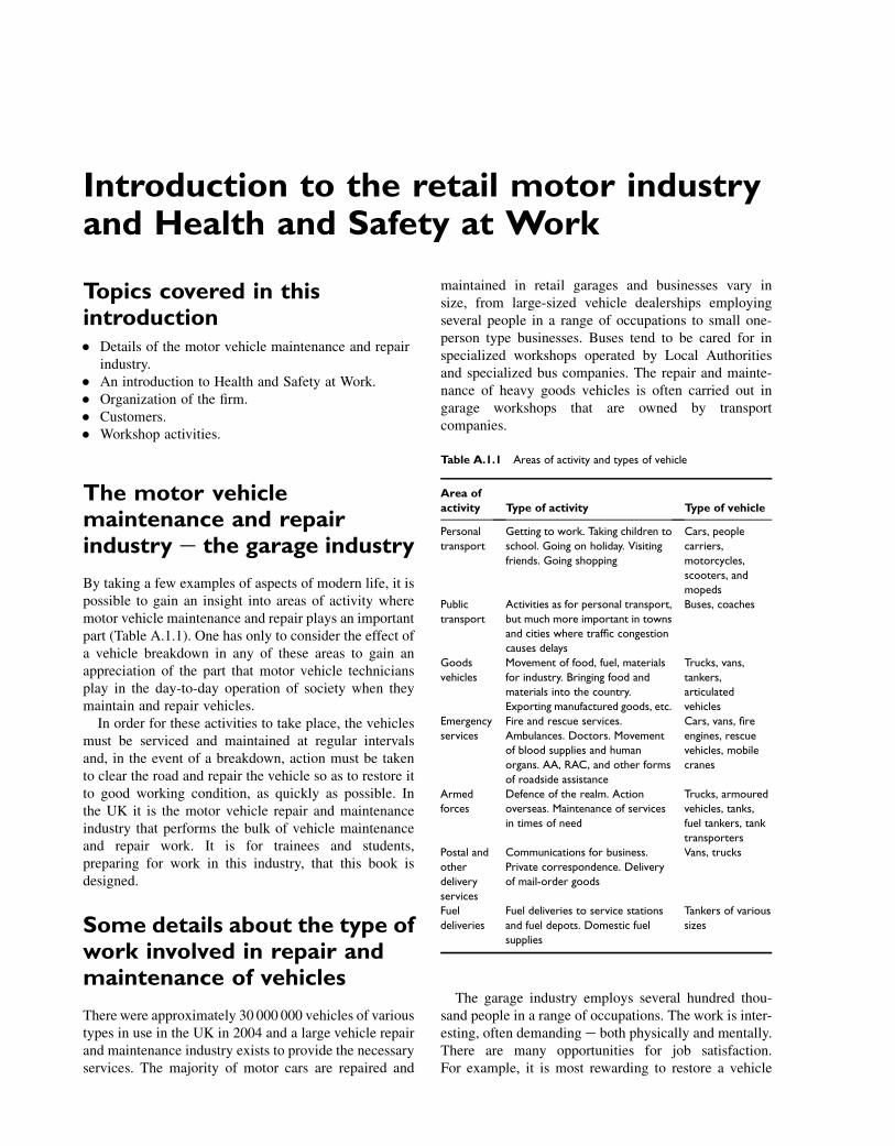
By taking a few examples of aspects of modern life, it ispossible to gain an insight into areas of activity wheremotor vehicle maintenance and repair plays an importantpart (Table A.1.1). One has only to consider the effect ofa vehicle breakdown in any of these areas to gain anappreciation of the part that motor vehicle techniciansplay in the day-to-day operation of society when theymaintain and repair vehicles.
In order for these activities to take place, the vehiclesmust be serviced and maintained at regular intervalsand, in the event of a breakdown, action must be takento clear the road and repair the vehicle so as to restore itto good working condition, as quickly as possible. Inthe UK it is the motor vehicle repair and maintenanceindustry that performs the bulk of vehicle maintenanceand repair work. It is for trainees and students,preparing for work in this industry, that this book isdesigned.
Some details about the type ofwork involved in repair andmaintenance of vehicles
There were approximately 30 000 000 vehicles of varioustypes in use in the UK in 2004 and a large vehicle repairand maintenance industry exists to provide the necessaryservices. The majority of motor cars are repaired and
maintained in retail garages and businesses vary insize, from large-sized vehicle dealerships employingseveral people in a range of occupations to small one-person type businesses. Buses tend to be cared for inspecialized workshops operated by Local Authoritiesand specialized bus companies. The repair and mainte-nance of heavy goods vehicles is often carried out ingarage workshops that are owned by transportcompanies.
The garage industry employs several hundred thou-sand people in a range of occupations. The work is inter-esting, often demanding e both physically and mentally.There are many opportunities for job satisfaction.For example, it is most rewarding to restore a vehicle
Table A.1.1 Areas of activity and types of vehicle
Area of
activity Type of activity Type of vehicle
Personal
transport
Getting to work. Taking children to
school. Going on holiday. Visiting
friends. Going shopping
Cars, people
carriers,
motorcycles,
scooters, and
mopeds
Public
transport
Activities as for personal transport,
but much more important in towns
and cities where traffic congestion
causes delays
Buses, coaches
Goods
vehicles
Movement of food, fuel, materials
for industry. Bringing food and
materials into the country.
Exporting manufactured goods, etc.
Trucks, vans,
tankers,
articulated
vehicles
Emergency
services
Fire and rescue services.
Ambulances. Doctors. Movement
of blood supplies and human
organs. AA, RAC, and other forms
of roadside assistance
Cars, vans, fire
engines, rescue
vehicles, mobile
cranes
Armed
forces
Defence of the realm. Action
overseas. Maintenance of services
in times of need
Trucks, armoured
vehicles, tanks,
fuel tankers, tank
transporters
Postal and
other
delivery
services
Communications for business.
Private correspondence. Delivery
of mail-order goods
Vans, trucks
Fuel
deliveries
Fuel deliveries to service stations
and fuel depots. Domestic fuel
supplies
Tankers of various
sizes
to full working condition after it has suffered some formof failure. There are opportunities for promotion, techni-cians often progressing to service managers and generalmanagers, or to run their own companies. The Office ofFair Trading (OFT) report for the year 2000 shows thatmore than 50% of cars were more than 5 years old. Thesecars require annual MOT inspections and there isa tendency for them to be serviced and repaired in theindependent sector of the industry. The OFT reportshows that there are approximately 16 000 independentgarages and 6500 garages that are franchised to one ormore motor manufacturers. Evidently there are plentyof opportunities for employment.
Health and safety
It is the responsibility of every person involved in workto protect their own safety and that of any other personswho may be affected by their activities. At the basiclevel this means that everyone must work in a safemanner and know how to react in an emergency.Personal cleanliness issues such as regular washing,removal of substances from skin, use of barrier creams,use of protective clothing and goggles and gloves, etc.are factors that contribute to one’s well being. Behavingin an orderly way, not indulging in horseplay, learninghow to employ safe working practices, and helping tokeep the workplace clean and tidy are all ways in whichan individual can contribute to their own and others’health and safety at work.
There are various laws and regulations that governworking practice in the motor vehicle repair industry,in the UK e the main ones are:
� Health & Safety at Work Act 1974� The Factories Act 1961� The Offices, Shops and Railway Premises Act 1963.
Some of the other regulations that relate to safety inmotor vehicle repair and maintenance are:
� The Control of Substances Hazardous to Health(COSHH) Regulations 1988
� Regulations about the storage and handling offlammable liquids
� The Grinding Wheel Regulations.
Health and safety laws are enforced by a factoryinspector from the Health and Safety Executive (HSE)or an environmental health officer from the local council.
Safety policy
As stated at the beginning of this section, each individualhas a responsibility to work safely and to avoid causingdanger to anyone else. This means that each individualmust know how to perform their work in a safe way and
how to react with other people in the event of an accidentor emergency. In any establishment, however small, safetyplanning must be performed by a competent person, whomust then familiarize all others engaged in the enterprisewith the plans that have been devised, to ensure that allhealth and safety issues are properly covered. These plansare a set of rules and guidelines for achieving health andsafety standards, in effect a policy.
Every motor vehicle repair business that employsfive or more people must write down their policy forhealth and safety and have it to hand for inspection bythe HSE.
Motor vehicle repair andmaintenance health and safetytopics
Readers are advised to purchase a copy of the publicationHealth and Safety in Motor Vehicle Repair and AssociateIndustries, HSG261 (2009) available from HMSO forapproximately £13. The HSE website, www.hse.gov.uk,is also a valuable source of information. Several pagesare devoted to motor vehicle repair and the home pageoffers the user the opportunity to select ‘your industry’,a click on ‘Motor vehicle repair’ brings up many opportu-nities to study a variety of health and safety topics.
This publication (HSG261) states that:
‘Most accidents in Motor Vehicle Repair (MVR)involve slips, trips and falls or occur during liftingand handling, and often cause serious injury.Crushing incidents involving the movement orcollapse of vehicles under repair result in seriousinjuries and deaths every year. Petrol-related workis a common cause of serious burns and fires, somefatal.
There is also widespread potential for work-related ill health in MVR. Many of the substancesused require careful storage, handling and control.Isocyanate-containing paints have been thebiggest cause of occupational asthma in the UK formany years and MVR is also in the top ten indus-tries for cases of disabling dermatitis. Use ofpower tools can cause vibration white finger.
This guidance has been developed in consulta-tion with representatives from the MVR industryand describes good practice. Following it shouldhelp you reduce the likelihood of accidents ordamage to health. The book is divided into twomain sections, one has guidance for specificindustry sectors and the other provides extensiveadvice on common MVR issues.’
From this you might think that motor vehicle work ishazardous but, if work is carried out properly and safety
xvi Introduction

factors are always considered, it is possible to workwithout injury to anyone. Safety training and relatedskills training must figure prominently in any course ofeducation and training that aims to prepare people forwork in motor vehicle maintenance and repair. Thefollowing descriptions are intended to highlight someof the everyday safety issues.
The information contained in this book does notattempt to provide full coverage of all safety and healthissues. The information provided merely draws attentionto some safety issues, and is not intended to cover allareas of safety. Readers should ensure that any educationcourse, training scheme, apprenticeship or other trainingarrangement does contain all necessary safety training.
Lifting equipment
The types of lifting equipment that are commonly usedin vehicle repair workshops are: jacks of various types,axle stands, vehicle hoists (lifts), floor cranes, andvehicle recovery equipment. Hydraulic jacks are usedto raise the vehicle. For work to be done underneaththe vehicle, the vehicle must be on level ground, andthe wheels that are remaining on the ground must bechocked or have the handbrake applied. Axle standsmust be placed in the correct positions before anyattempt is made to get under the vehicle. Figure A.1.1shows the hydraulic jack placed at a suitable jackingpoint. This is important: (i) to ensure that the jackingpoint is secure from the safety point of view; and (ii)to prevent damage to the vehicle.
Hydraulic jacks must be maintained in good condition.The safe working load must be clearly marked on thejack. Axle stands must be of good quality and of aload-carrying capacity that is correct for the vehiclebeing supported on them. The proper pins that allowfor height adjustment should be attached to the standsand the stands must be kept in good condition.
Vehicle hoists
The two-post vehicle hoist shown in Fig. A.1.2 is anexample of a type that is widely used in the garageindustry. The HSE guide (HSG261) states:
‘Two-post lifts typically consist of two uprightcolumns: a master or powered column. plus anauxiliary or ‘slave’, both fitted with a pair of(vehicle) carrying arms. These arms are pivoted atthe column and their lengths are adjustable,usually by telescopic means, though some arearticulated. At the free end of each carrying armthere is an adjustable pick-up plate fitted witha rubber mounting pad. A two-post lift achieves‘wheel-free lifting’ by aligning the pick-up platesto four jacking points on the underside of thechassis of the vehicles. It is important that:
� you follow the vehicle manufacturer’srecommendations regarding vehicle lifting. Inparticular, you need to ensure the equipment issuitable when lifting larger SUV and ‘light’ freightand commercial vans (LCVs);
� vehicle chassis and chassis jack points are identifiableand in a satisfactory condition. Vehicle jacking pointsare usually identified by a symbol on the vehicle sill, ifin doubt always consult the car handbook;
� the support-arm rubber mounting pads are inserviceable condition and, where necessary, forexample to avoid the lift arm fouling the carbodywork, are set at the correct height before thevehicle is raised;
� the lifting arms are carefully positioned before eachlift, in accordance with the manufacturer’sinstructions. This is to ensure correct weightdistribution and proper contact with load-bearingpoints so the vehicle is stable. Also take account of theweight distribution of the vehicle, e.g. front/rear
ER/11/5 TI
(a)
ER/11/6 T1
(b)
Fig. A.1.1 (a) Hydraulic jack positioned at jacking point. (b) Axle stands in position prior to working under the vehicle. (Reproduced with the kind
permission of Ford Motor Company Limited.)
Introduction xvii

engined, loads within vehicle/boot, and absence ofmajor components such as engine or gearbox;
� you consider the effect on the stability of the vehiclecaused by the removal of major components or by theapplication of forces, via tools etc;
� the lift arms are fitted with an effective automaticmechanical arm locking system to maintain the anglebetween them. These should be checked regularly etypically daily.
� It is essential that two-post lifts are installed correctlyinto a suitable base. This is particularly importantwhere the posts are free-standing (with no bridgingsupport). Specialist advice may be required to ensurethe structural integrity of the floor and fixings and thelift supplier or specialist garage equipmentmaintenance company should be consulted.’
Comment
Hoists, in common with other equipment, should not beused until the method of operation is properly understood.For trainees this means that proper training must beprovided and trainees should not attempt to use hoists untilthey have been trained and given permission to do so. Partof that training will be a demonstration of the procedurefor locating jacking points and positioning the supportarm pads. This ensures that the vehicle will be stablewhen lifted and the support arm pads prevent damage tothe vehicle structure. The weight distribution of thevehicle on the hoist will be affected according to thework being performed. For example, if the hoist is beingused during a transmission unit change, the removal ofthe transmission unit will greatly affect weight distribu-tion and this must be allowed for as the work progresses.
Regarding four-post hoists, the HSE guide (HSG261)says that:
‘Four-post hoists should have effective “deadman’s” controls, toe protection and automaticchocking. Toe traps should also be avoided whenbody straightening jigs are fitted. Raised platformsshould never be used as working areas unlessproper working balconies or platforms withbarrier rails are provided.’
Greater detail is given on pages 45e46 of HSG261.
Comment
The dead man’s control is designed to avoid mishapsduring the raising and lowering of the hoist. Toe protec-tion is to prevent damage to the feet when the hoist islowered to the ground, and the automatic chocking isto prevent the vehicle from being accidentally rolledoff the raised hoist. Body straightening jigs are used invehicle body repair shops and their use requires specialtraining. The point about working above floor level andthe use of balconies should be noted.
In general, hoists make work on the underside ofa vehicle less demanding than lying on one’s back. Apoint to note is that hard hats should be worn whenworking under a vehicle on a hoist. The area aroundthe hoist must be kept clear and a check should alwaysbe made when lowering or raising a hoist to ensurethat no person, vehicle, or other object is likely to beharmed by the operation. Hoists must be frequentlyexamined to ensure that they are maintained in safeworking order.
Fig. A.1.2 Wheel-free post hoist. (Reproduced with the kind permission of Rover Motor Company Limited.)
xviii Introduction
Electrical safety
Safety in the use of electrical equipment must figureprominently at all stages of training.
Learning taskAs an exercise to develop knowledge in this area youshould now read pages 72e79 of HSG261 andcompare that with the training and tuition that youare receiving. Also visit the HSE motor vehicle repairwebsite and study what it has to say about electricalsafety. Check with your supervisor to make sure thatyou know what to do in the event of an electricalemergency in your present circumstances.
Compressed air equipment
Compressed air is used in a number of vehicle repairoperations such as tyre inflation, pneumatic tools,greasing machines, oil dispensers, etc. The compressedair is supplied from a compressor and air cylinder, thisis equipment that must be inspected regularly bya competent person. The usual procedure is for the insur-ance company to perform this work. Air lines, hoses, tyreinflaters, pressure gauges, couplings, etc. should beinspected at regular intervals to ensure that they arekept in working order. Inflation of the split rim type ofcommercial vehicle tyres requires special attention andthe tyres should only be inflated behind a speciallydesigned guard. The HSE publication HSG261 coversmany aspects of health and safety for those engaged intyre and exhaust fitting work.
Learning taskRead pages 55e60 of HSG261 and make notes aboutthe main points. Discuss these points with your tutorand class mates.
Petrol fires
Referring back to the statement at the beginning of thissection we have:
‘Petrol-related work is a common cause of seriousburns and fires, some fatal.’
Comment
Petrol gives off a flammable vapour that is heavierthan air; this means that it will settle at a low leveland spread over a wide area. Petrol vapour is alsoinvisible. The vapour can be ignited by a flame orspark at some distance from any visible sign of theliquid. Great care must be exercised when dealing
with petrol and the appropriate fire extinguishershould be close to hand when performing any taskinvolving petrol or any other flammable substance.Petrol may only be stored in containers specified inthe Petroleum Spirit Regulations. Advice on this isreadily available from the local Fire Authority. Inthe event of spillage on clothes, the clothes shouldbe removed for cleaning because petrol vapour canaccumulate inside the clothing, which can result inserious burns in the event of ignition.
Learning taskRead page 66 of HSG261. What does HSG261 sayabout the fuel gauge sender unit? Discuss this withyour tutor/trainer, or supervisor.
Brake and clutch linings
‘There is also widespread potential for workrelated ill-health in garages. Many of thesubstances used require careful storage, handlingand control.’
(HSG261)
Some brake and clutch linings contain asbestos. Toguard against harmful effects special measures must beemployed. These measures include wearing a mask,using an appropriate vacuum cleaner to remove dustand preventing asbestos dust from getting into thesurrounding air.
Learning taskRead page 10 of HSG261 and then describe to yourtutor/trainer the type of vacuum cleaner that shouldbe used to remove brake lining or clutch lining dust.Also explain the purpose of wetting any dust thatmay have been left on the floor.
Oils and lubricants
Oils and lubricants used in vehicles contain chemicalsto change their properties and make them suitablefor use in many vehicle applications. Many of thechemicals used are harmful to health if not handledproperly.
Used oils must only be disposed of in approvedways. Special containers are available for receivingoil as it is drained from a vehicle. Vehicle repair work-shops must have facilities to store used oil prior todisposing of it through approved channels. Used oilhas a market value and some companies collect it forreprocessing.
Introduction xix
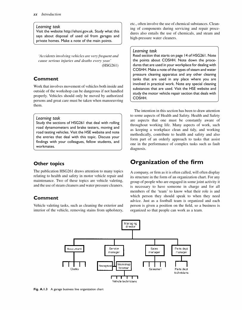
Learning taskVisit the website http://ehsni.gov.uk. Study what thissays about disposal of used oil from garages andprivate homes. Make a note of the main points.
‘Accidents involving vehicles are very frequent andcause serious injuries and deaths every year.’
(HSG261)
Comment
Work that involves movement of vehicles both inside andoutside of the workshop can be dangerous if not handledproperly. Vehicles should only be moved by authorizedpersons and great care must be taken when manoeuvringthem.
Learning taskStudy the sections of HSG261 that deal with rollingroad dynamometers and brake testers, moving androad testing vehicles. Visit the HSE website and notethe entries that deal with this topic. Discuss yourfindings with your colleagues, fellow students, andworkmates.
Other topics
The publication HSG261 draws attention to many topicsrelating to health and safety in motor vehicle repair andmaintenance. Two of these topics are vehicle valeting,and the use of steam cleaners and water pressure cleaners.
Comment
Vehicle valeting tasks, such as cleaning the exterior andinterior of the vehicle, removing stains from upholstery,
etc., often involve the use of chemical substances. Clean-ing of components during servicing and repair proce-dures also entails the use of chemicals, and steam andhigh-pressure water cleaners.
Learning taskRead section that starts on page 14 of HSG261. Notethe points about COSHH. Note down the proce-dures that are used in your workplace for dealing withCOSHH. Make a note of the types of steam and waterpressure cleaning apparatus and any other cleaningtanks that are used in any place where you areinvolved in practical work. Note any special cleaningsubstances that are used. Visit the HSE website andstudy the motor vehicle repair section that deals withCOSHH.
The intention in this section has been to draw attentionto some aspects of Health and Safety. Health and Safetyare aspects that one must be constantly aware ofthroughout working life. Many aspects of work, suchas keeping a workplace clean and tidy, and workingmethodically, contribute to health and safety and alsoform part of an orderly approach to tasks that assistone in the performance of complex tasks such as faultdiagnosis.
Organization of the firm
A company, or firm as it is often called, will often displayits structure in the form of an organization chart. For anygroup of people who are engaged in some joint activity itis necessary to have someone in charge and for allmembers of the ‘team’ to know what their role is andwhich person they should speak to when they needadvice. Just as a football team is organized and eachperson is given a position on the field, so a business isorganized so that people can work as a team.
Fig. A.1.3 A garage business line organization chart
xx Introduction
The ‘line chart’ (Fig. A.1.3) shows how the work isdivided up into manageable units, or areas of work,and how the personnel in those areas relate to eachother. In this example the managing director is the‘boss’. Under the managing director come the accoun-tant, the service manager, the parts departmentmanager, and the sales manager; these are known as‘line’ managers. Below these line managers, in the hier-archical structure that is used in many businesses, aresupervisors (foremen/women) and then come the tech-nicians, clerks, etc.
Policy
A policy is a set of rules and guidelines that should bewritten down so that everyone in an organization knowswhat they are trying to achieve. Policy is decided by thepeople at the top of an organization, in consultation withwhoever else they see fit. It is important for eachemployee to know how policy affects them and it shouldbe suitably covered in a contract of employment. Forexample, every firm must have a ‘safety policy’. It isthe duty of every employee to know about safety andfirms are subject to inspection to ensure that they arecomplying with the laws that relate to health and safetyat work, and similar legislation.
Discipline
Standards of workmanship, hours of work, relations withother employees, relations with customers, and manyother factors need to be overseen by members of thefirm who have some authority because, from time totime, it may be necessary to take steps to change someaspect. For example, it may be the case that a particulartechnician is starting to arrive late for work; it will benecessary for someone to deal with this situation beforeit gets out of hand and this is where the question of‘authority’ arises.
Authority
Authority is power deriving from position. The organiza-tion chart illustrates who has authority (power) overwhom. The vertical position on the chart of a memberof staff indicates that they are in charge of, and havepower over, the employees lower down the chart. Theservice manager in a garage has authority in relation tothe operation of the workshop; in addition they areresponsible for the satisfactory performance of the work-shop side of the business.
Accountability
We all have to account for actions that we take. Thismeans having to explain why we took a particular lineof action. We are all responsible for the actions that wetake. This means that we did certain things that led tosome outcome. By having to explain why something‘went wrong’, i.e. by having to account for our behaviour,we are made to examine our responsibility. We are‘responsible’ for seeing that we get to work on time, formaking sure that we do a job properly and safely, andfor helping to promote good working relationships.
Delegating
It is often said that you can delegate (pass down)authority but not responsibility. So, if you are a skilledtechnician who has a trainee working with you and youhave been given a major service to do, it will be yourresponsibility to ensure that the job is done properly.You will have had some authority given to you to instructthe trainee, but the responsibility for the quality of thework remains with you.
Having introduced some ideas about business organi-zation and the working relationships that are necessaryto ensure success, we can turn our attention to the businessactivities that are the immediate concern of the servicetechnician. In order to place some structure on this sectionit is probably a good idea to start with ‘reception’.
Reception
Reception in a garage is themain point of contact betweencustomers and the services that the workshop provides. Itis vitally important that the communication between thecustomers and reception and between reception and theworkshop is good. It is at reception that the customerwill hand over the vehicle and it is at reception that itwill be handed back to the customer. The reception engi-neer is a vital link in the transaction between the customerand the firm, and it is at this point that frictionmay occur ifsomething has gone wrong. Staff in reception need to becool headed, able to think on their feet, and equippedwith a vocabulary that enables them to copewith any situ-ation thatmay ‘crop up’. From time to time theymay needto call on the assistance of the service manager and it isvitally important that there are good relations and clearlines of communication in this area.
In many garages there will be an area set aside forreception and the staff placed there will have set dutiesto perform. In the case of small garages employing,perhaps, one or two people, reception may take placein the general office and the person who is free at thetime may perform the function. In either case, certainprinciples apply and it is these that are now addressed.
Introduction xxi
Customer categories
Because a good deal of skill and tact is required whendealing with customers it is useful to categorize themas follows:
� informed� non-informed� new� regular.
Informed customers
Informed customers are those who are knowledgeableabout their vehicle and who probably know the wholeprocedure that the vehicle will follow before it isreturned to them. This means that the transaction thattakes place between them and the receptionist willlargely consist of taking down details of the customer’srequirements and agreeing a time for the completion ofthe work and the collection of the vehicle. Dependingon the status of the customer, i.e. new or regular, it willbe necessary to make arrangements for payment. Itmay also be necessary to agree details for contactingthe customer should some unforeseen problem arisewhile work on the vehicle is in progress, so that detailscan be discussed and additional work and a newcompletion time agreed.
Non-informed customers
The non-informed customer probably does not knowmuch about cars or the working procedures of garages.This type of customer will need to be treated in quitea different way. The non-informed customer will edepending on the nature of the work they require fortheir vehicle e need to have more time spent onthem. A proportion of this extra time will be devotedto explaining what the garage is going to do with theirvehicle and also what the customer has to do while thevehicle is in the care of the garage. The latter part willlargely consist of making arrangements for getting thecustomer to some chosen destination and for collect-ing the vehicle when the work is completed. On hand-ing the car back to the ‘non-informed’ customer it willprobably be necessary to describe, in a non-patron-izing and not too technical way, the work that hasbeen done and what it is that they are being askedto pay for.
New customers
A ‘new’ customer may be informed or non-informed andthis is information that should be ‘teased’ out during theinitial discussions with them. Courtesy and tact are key
words in dealing with customers and they are factorsthat should be uppermost in one’s mind at the new-customer-introduction stage. The extent of the introduc-tory interview with the new customer will depend onwhat it is that they want done and the amount of timethat they and the firm have to give to the exercise. If itis a garage with several departments it may be advisableto introduce the new customer to relevant personnel inthe departments that are most likely to be concernedwith them. Customers may wish to know that theirvehicle will be handled by qualified staff and it iscommon practice for firms to display samples of staffqualification certificates in the reception area. At somestage it will be necessary to broach the subject ofpayment for services and this may be aided by the firmhaving a clearly stated policy. Again, it is not uncommonfor a notice to be displayed which states the ‘terms ofbusiness’; drawing a client’s attention to this is relativelyeasy.
Regular customers
Regular customers are valuable to a business and theyshould always be treated with respect. It hardly needssaying that many of the steps that are needed for thenew customer introduction will not be needed whendealing with a regular customer. However, customerswill only remain loyal (regular) if they are properlylooked after. It is vitally important to listen carefully totheir requests and to ensure that the work is done prop-erly and on time, and that the vehicle is returned tothem in a clean condition.
Workshop activities
Reception will have recorded the details of the workthat is to be done on the vehicle, and they will haveagreed details of completion time, etc. with the work-shop. At some point in the process a ‘job card’ willhave been generated. The instructions about the workto be done must be clear and unambiguous. In somecases this may be quite brief e for example, 10 000mile service. The details of the work to be performedwill be contained in the service manual for the partic-ular vehicle model. In other cases it may be rathergeneral e for example, ‘Attend to noisy wheel bearing.Near side front.’ Describing exactly what work isrequired may entail further investigation by the techni-cian. It may be that the noise is caused by the finaldrive. The whole thing thus becomes much morecomplicated and it may be necessary to conducta preliminary examination and test of the vehicle beforethe final arrangements are made for carrying out thework.
xxii Introduction

Once the vehicle has been handed over to the work-shop with a clear set of instructions about the work tobe done, it becomes the responsibility of the techni-cian entrusted with the job and their colleagues toget the work done efficiently and safely, and tomake sure that the vehicle is not damaged. This meansthat the workshop must have all necessary interior andexterior protection for the vehicle such as wing andseat covers, etc. Figure A.1.4 shows a suggested layoutfor a service bay.
Records
As the work proceeds a record must be made ofmaterials used and time spent because this will beneeded when making out the invoice. In large organi-zations the workshop records will be linked to stockcontrol in the parts department and to other
departments, such as accounts, through the company’sinformation system, which will probably be computerbased.
Quality control
Vehicle technicians are expected to produce work of highquality and various systems of checking work aredeployed. One aspect of checking quality that usuallyexcites attention is the ‘road test’. It is evident that thiscan only be performed by licensed drivers and it isusually restricted to experienced technicians. A roadtest is an important part of many jobs because it is prob-ably the only way to ensure that the vehicle is func-tioning correctly. It is vitally important that it isconducted in a responsible way. Figure A.1.5 illustratesthe point that there must be a good clear road in frontof and behind the vehicle.
Fig. A.1.4 A service bay
Introduction xxiii

Returning the vehicle to thecustomer
On satisfactory completion of the work, the vehiclewill be taken to the customer’s collection point; thecovers and finger marks, and other small blemishesshould be removed. In the meantime the accountsdepartment will, if it is a cash customer, have preparedthe account so that everything is ready for completionof the transaction when the customer collects thevehicle.
Fig. A.1.5 The front and rear view of the road when road testing
xxiv Introduction

1Vehicle layouts and some simple vehiclestructures
Topics covered in thischapter
The types of forces to which a vehicle structure issubjectedUnitary constructionChassis-built vehiclesFront- and rear-wheel drive and the layout of thesesystemsPassenger protection e crumple zones and side impactbarsVehicle shape e air resistancePros and cons of front- and rear-wheel-drive systemsEnd-of-life vehicles and methods of disposal
Light vehicles
The term light vehicle is generally taken to meanvehicles weighing less than 3 tonnes. These are vehiclessuch as cars, vans, and light commercial vehicles.Various types of light vehicles are shown in Fig. 1.1.Most of these vehicles are propelled by an internalcombustion engine but increasing concern aboutatmospheric pollution is causing greater use of electricpropulsion. Vehicles that incorporate an internalcombustion engine and an electric motor are calledhybrid vehicles.
Vehicle structure
Figure 1.2 shows some of the forces that act on a vehiclestructure. The passengers and other effects cause a down-ward force that is resisted by the upward forces at theaxles. The vehicle structure acts like a simple beamwhere the upper surface is in compression and the lowerone in tension. When the loading from side to side of thevehicle is unequal the vehicle body is subject to a twistingeffect and the vehicle structure is designed to havetorsional stiffness that resists distortion through twisting.
There are basically two types of vehicle construction:one uses a frame on to which the vehicle is built; theother is called unitary construction where the bodyand frame are built as a unit to which subframes areadded to support the suspension and other components.
The frame is normally made from low-carbon steelthat is formed into shapes to provide maximum strength;box and channel sections are frequently used for thispurpose. The frame shown in Fig. 1.3 has a deepersection in the centre area of the side members becausethis is where the bending stress is greatest. In areaswhere additional strength is required, such as wheresuspension members are attached, special strengtheningsupports are fitted.
Unitary construction
Most of the vehicle structure is made from steel sectionsthat are welded together to provide a rigid structurewhich is able to cope with the stresses and strains thatoccur when the vehicle is in use. In most cases the mate-rial used is a deep-drawing mild steel that can be readilypressed into the required shapes. An example of unitaryconstruction is shown in Fig. 1.4. In some cases, theouter panels are made from plastics such as Kevlar(Fig. 1.5), which has excellent strength and resistanceto corrosion.
Body panels are normally lined with sound-deadeningmaterial which is either sprayed, or glued, on to theinside. In order to protect body components againstrust and corrosion, they may be galvanized, or treatedwith some other form of protection.
Passenger protection
In addition to providing the strength required for normalmotoring conditions, vehicles are designed to protect theoccupants in the event of a collision. Two areas of vehicleconstruction are particularly related to this problem:
1. Crumple zones2. Side impact protection.
� 2011 Allan Bonnick and Derek Newbold. Published by Elsevier Ltd. All rights reserved
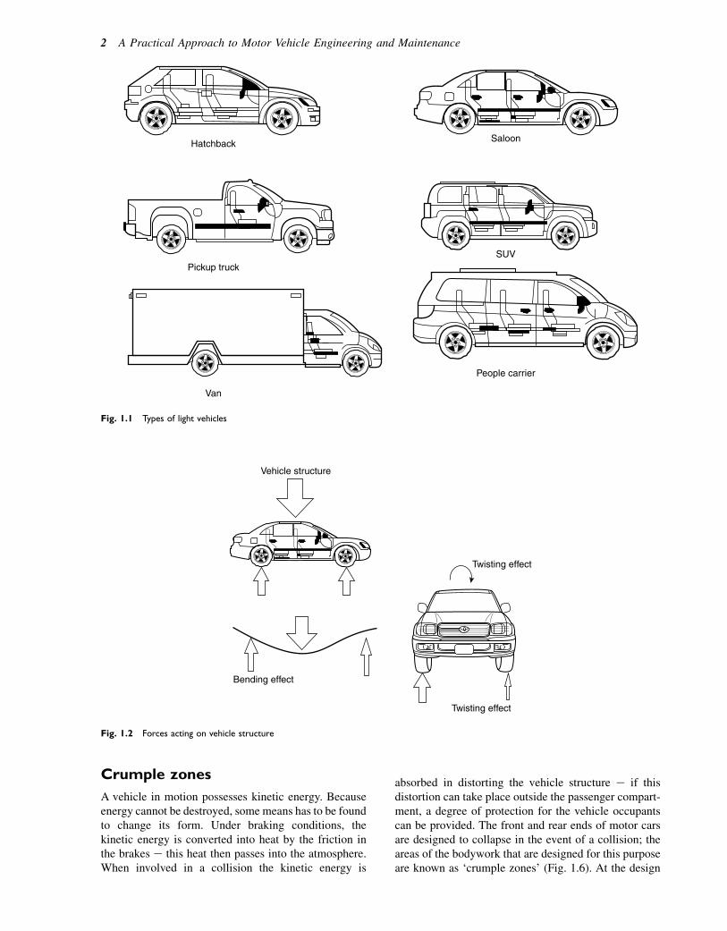
Crumple zones
A vehicle in motion possesses kinetic energy. Becauseenergy cannot be destroyed, some means has to be foundto change its form. Under braking conditions, thekinetic energy is converted into heat by the friction inthe brakes e this heat then passes into the atmosphere.When involved in a collision the kinetic energy is
absorbed in distorting the vehicle structure e if thisdistortion can take place outside the passenger compart-ment, a degree of protection for the vehicle occupantscan be provided. The front and rear ends of motor carsare designed to collapse in the event of a collision; theareas of the bodywork that are designed for this purposeare known as ‘crumple zones’ (Fig. 1.6). At the design
Van
People carrier
SUV
SaloonHatchback
Pickup truck
Fig. 1.1 Types of light vehicles
Vehicle structure
Bending effect
Twisting effect
Twisting effect
Fig. 1.2 Forces acting on vehicle structure
2 A Practical Approach to Motor Vehicle Engineering and Maintenance

Cross members
Suspension mounts
Box section side membersFront
Rear
Fig. 1.3 A typical vehicle frame
Radiator grill panel
Wing valance
Bulk head
A Pillar
Sill
Floor panel
Cant rail
B Pillar
C Pillar
Fig. 1.4 Features of a unitary construction body
Boot lidmade fromKevlar
Fig. 1.5 Kevlar body panel
Fig. 1.6 Crumple zone e impact test at the British Transport
Research Laboratory (TRL)
Image Courtesy of StaraBlazkova at the Czech language Wikipedia
Vehicle layouts and some simple vehicle structures 3
and development stages, and prior to introduction intogeneral use, samples of vehicles are subjected torigorous tests to ensure that they comply with the stan-dards that are set by governmental bodies.
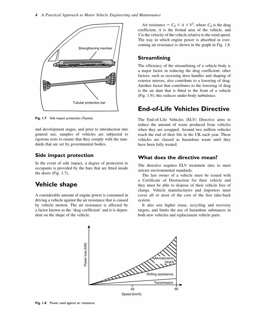
Side impact protection
In the event of side impact, a degree of protection tooccupants is provided by the bars that are fitted insidethe doors (Fig. 1.7).
Vehicle shape
A considerable amount of engine power is consumed indriving a vehicle against the air resistance that is causedby vehicle motion. The air resistance is affected bya factor known as the ‘drag coefficient’ and it is depen-dent on the shape of the vehicle.
Air resistance 5 Cd 3 A 3 V2, where Cd is the dragcoefficient, A is the frontal area of the vehicle, andV is the velocity of the vehicle relative to the wind speed.The way in which engine power is absorbed in over-coming air resistance is shown in the graph in Fig. 1.8.
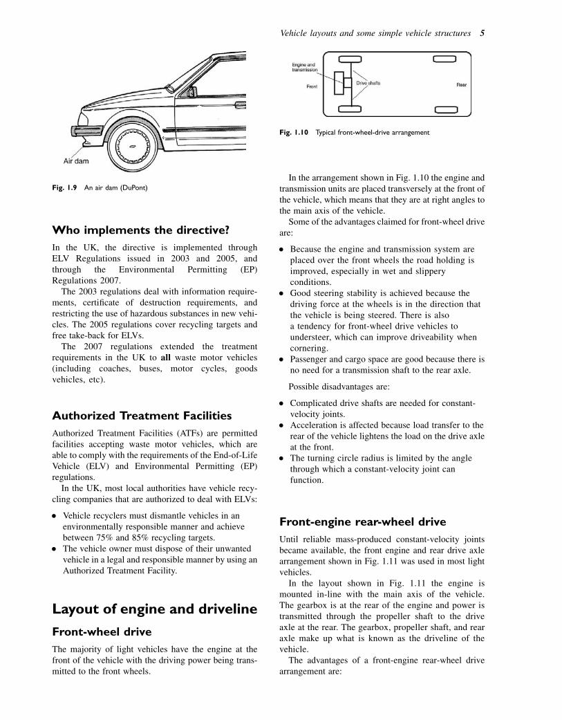
Streamlining
The efficiency of the streamlining of a vehicle body isa major factor in reducing the drag coefficient; otherfactors, such as recessing door handles and shaping ofexterior mirrors, also contribute to a lowering of drag.Another factor that contributes to the lowering of dragis the air dam that is fitted to the front of a vehicle(Fig. 1.9); this reduces under-body turbulence.
End-of-Life Vehicles Directive
The End-of-Life Vehicles (ELV) Directive aims toreduce the amount of waste produced from vehicleswhen they are scrapped. Around two million vehiclesreach the end of their life in the UK each year. Thesevehicles are classed as hazardous waste until theyhave been fully treated.
What does the directive mean?
The directive requires ELV treatment sites to meetstricter environmental standards.
The last owner of a vehicle must be issued witha Certificate of Destruction for their vehicle andthey must be able to dispose of their vehicle free ofcharge. Vehicle manufacturers and importers mustcover all or most of the cost of the free take-backsystem.
It also sets higher reuse, recycling and recoverytargets, and limits the use of hazardous substances inboth new vehicles and replacement vehicle parts.
Strengthening member
Tubular protection bar
Fig. 1.7 Side impact protection (Toyota)
Rolling assistance
45
Speed [km/h]
90
Pow
er lo
ss [k
W]
Transmission
AerodynamicDHAS
Fig. 1.8 Power used against air resistance
4 A Practical Approach to Motor Vehicle Engineering and Maintenance
Who implements the directive?
In the UK, the directive is implemented throughELV Regulations issued in 2003 and 2005, andthrough the Environmental Permitting (EP)Regulations 2007.
The 2003 regulations deal with information require-ments, certificate of destruction requirements, andrestricting the use of hazardous substances in new vehi-cles. The 2005 regulations cover recycling targets andfree take-back for ELVs.
The 2007 regulations extended the treatmentrequirements in the UK to all waste motor vehicles(including coaches, buses, motor cycles, goodsvehicles, etc).
Authorized Treatment Facilities
Authorized Treatment Facilities (ATFs) are permittedfacilities accepting waste motor vehicles, which areable to comply with the requirements of the End-of-LifeVehicle (ELV) and Environmental Permitting (EP)regulations.
In the UK, most local authorities have vehicle recy-cling companies that are authorized to deal with ELVs:
� Vehicle recyclers must dismantle vehicles in anenvironmentally responsible manner and achievebetween 75% and 85% recycling targets.
� The vehicle owner must dispose of their unwantedvehicle in a legal and responsible manner by using anAuthorized Treatment Facility.
Layout of engine and driveline
Front-wheel drive
The majority of light vehicles have the engine at thefront of the vehicle with the driving power being trans-mitted to the front wheels.
In the arrangement shown in Fig. 1.10 the engine andtransmission units are placed transversely at the front ofthe vehicle, which means that they are at right angles tothe main axis of the vehicle.
Some of the advantages claimed for front-wheel driveare:
� Because the engine and transmission system areplaced over the front wheels the road holding isimproved, especially in wet and slipperyconditions.
� Good steering stability is achieved because thedriving force at the wheels is in the direction thatthe vehicle is being steered. There is alsoa tendency for front-wheel drive vehicles toundersteer, which can improve driveability whencornering.
� Passenger and cargo space are good because there isno need for a transmission shaft to the rear axle.
Possible disadvantages are:
� Complicated drive shafts are needed for constant-velocity joints.
� Acceleration is affected because load transfer to therear of the vehicle lightens the load on the drive axleat the front.
� The turning circle radius is limited by the anglethrough which a constant-velocity joint canfunction.
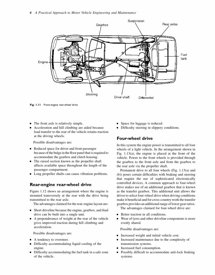
Front-engine rear-wheel drive
Until reliable mass-produced constant-velocity jointsbecame available, the front engine and rear drive axlearrangement shown in Fig. 1.11 was used in most lightvehicles.
In the layout shown in Fig. 1.11 the engine ismounted in-line with the main axis of the vehicle.The gearbox is at the rear of the engine and power istransmitted through the propeller shaft to the driveaxle at the rear. The gearbox, propeller shaft, and rearaxle make up what is known as the driveline of thevehicle.
The advantages of a front-engine rear-wheel drivearrangement are:
Fig. 1.9 An air dam (DuPont)
Fig. 1.10 Typical front-wheel-drive arrangement
Vehicle layouts and some simple vehicle structures 5
� The front axle is relatively simple.� Acceleration and hill climbing are aided because
load transfer to the rear of the vehicle retains tractionat the driving wheels.
Possible disadvantages are:
� Reduced space for driver and front passengerbecause of the bulge in the floor panel that is required toaccommodate the gearbox and clutch housing.
� The raised section known as the propeller shaftaffects available space throughout the length of thepassenger compartment.
� Long propeller shafts can cause vibration problems.
Rear-engine rear-wheel drive
Figure 1.12 shows an arrangement where the engine ismounted transversely at the rear with the drive beingtransmitted to the rear axle.
The advantages claimed for the rear-engine layout are:
� Short driveline because the engine, gearbox, and finaldrive can be built into a single unit.
� A preponderance of weight at the rear of the vehiclegives improved traction during hill climbing andacceleration.
Possible disadvantages are:
� A tendency to oversteer.� Difficulty accommodating liquid cooling of the
engine.� Difficulty accommodating the fuel tank in a safe zone
of the vehicle.
� Space for luggage is reduced.� Difficulty steering in slippery conditions.
Four-wheel drive
In this system the engine power is transmitted to all fourwheels of a light vehicle. In the arrangement shown inFig. 1.13(a), the engine is placed at the front of thevehicle. Power to the front wheels is provided throughthe gearbox to the front axle and from the gearbox tothe rear axle via the propeller shaft.
Permanent drive to all four wheels (Fig. 1.13(a) and(b)) poses certain difficulties with braking and steeringthat require the use of sophisticated electronicallycontrolled devices. A common approach to four-wheeldrive makes use of an additional gearbox that is knownas the transfer gearbox. This additional unit allows thedriver to select four-wheel drivewhen driving conditionsmake it beneficial and for cross-countrywork the transfergearbox provides an additional range of lower gear ratios.
The advantages claimed for four-wheel drive are:
� Better traction in all conditions.� Wear of tyres and other driveline components is more
evenly shared.
Possible disadvantages are:
� Increased weight and initial vehicle cost.� Increased maintenance due to the complexity of
transmission systems.� Increased fuel consumption.� Possibly difficult to accommodate anti-lock braking
systems.
Fig. 1.11 Front-engine rear-wheel drive
6 A Practical Approach to Motor Vehicle Engineering and Maintenance

Self-assessment questions1. What happens to a motor vehicle that has reached
the end of its useful life?2. Find out the names of the Authorized Treatment
Facilities in your area.3. What percentage of a vehicle is recycled? What
happens to the steel that is reclaimed whena vehicle is scrapped?
4. Examine a manual for a vehicle that you work onand describe the features that the design
incorporates to protect the occupants in the eventof a collision.
5. Write a few notes to describe why you think thatfour-wheel drive vehicles are now popular for useas family cars.
6. What is meant by the term ‘oversteer’. Why do youthink that a rear-engine vehicle may be more proneto oversteer than a front-engine vehicle?
7. What is the purpose of an air dam?8. What measures should be taken to protect
paintwork when a vehicle is being worked on?9. In which position on vehicle panels is soundproofing
applied?10. If the speed of a vehicle is doubled, by what factor is
the air resistance increased?11. What features of vehicle design affect the drag
coefficient?12. Which part of a four-wheel drive transmission
system permits the four-wheel drive to beengaged?
13. In which positions on a vehicle are the side impactprotection bars fitted?
14. Make a list of the external parts of a motor car thatare made from plastic.
15. What methods of joining body panels are used inmodern vehicle construction?
16. What materials and methods are used to preventwater entering the interior of a car?
17. Describe, with the aid of a diagram, the type ofengine mounting that is used to attach an engine toa vehicle frame.
Gearbox
Transfer box
Visco clutch and 60/40 diff
Front engine with 60/40 differentialand visco clutch
Transverse engine withtransaxle
(b)
(a)
Fig. 1.13 (a) Optional four-wheel drive. (b) Permanent four-wheel
drive
Fig. 1.12 Rear-engine rear-wheel-drive layout
Vehicle layouts and some simple vehicle structures 7
2Engine principles
Topics covered in thischapter
The Otto cycleCompression ratioThe two-stroke cycleThe Wankel rotary engineThe Atkinson cycle as adapted for use in hybrid vehiclesValve and ignition timingVariable valve lift and valve timing
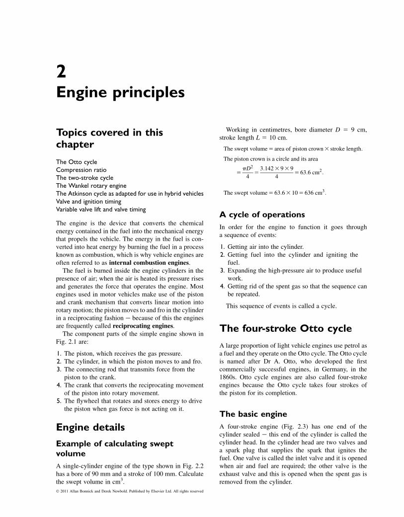
The engine is the device that converts the chemicalenergy contained in the fuel into the mechanical energythat propels the vehicle. The energy in the fuel is con-verted into heat energy by burning the fuel in a processknown as combustion, which is why vehicle engines areoften referred to as internal combustion engines.The fuel is burned inside the engine cylinders in the
presence of air; when the air is heated its pressure risesand generates the force that operates the engine. Mostengines used in motor vehicles make use of the pistonand crank mechanism that converts linear motion intorotary motion; the piston moves to and fro in the cylinderin a reciprocating fashion e because of this the enginesare frequently called reciprocating engines.The component parts of the simple engine shown in
Fig. 2.1 are:
1. The piston, which receives the gas pressure.2. The cylinder, in which the piston moves to and fro.3. The connecting rod that transmits force from the
piston to the crank.4. The crank that converts the reciprocating movement
of the piston into rotary movement.5. The flywheel that rotates and stores energy to drive
the piston when gas force is not acting on it.
Engine details
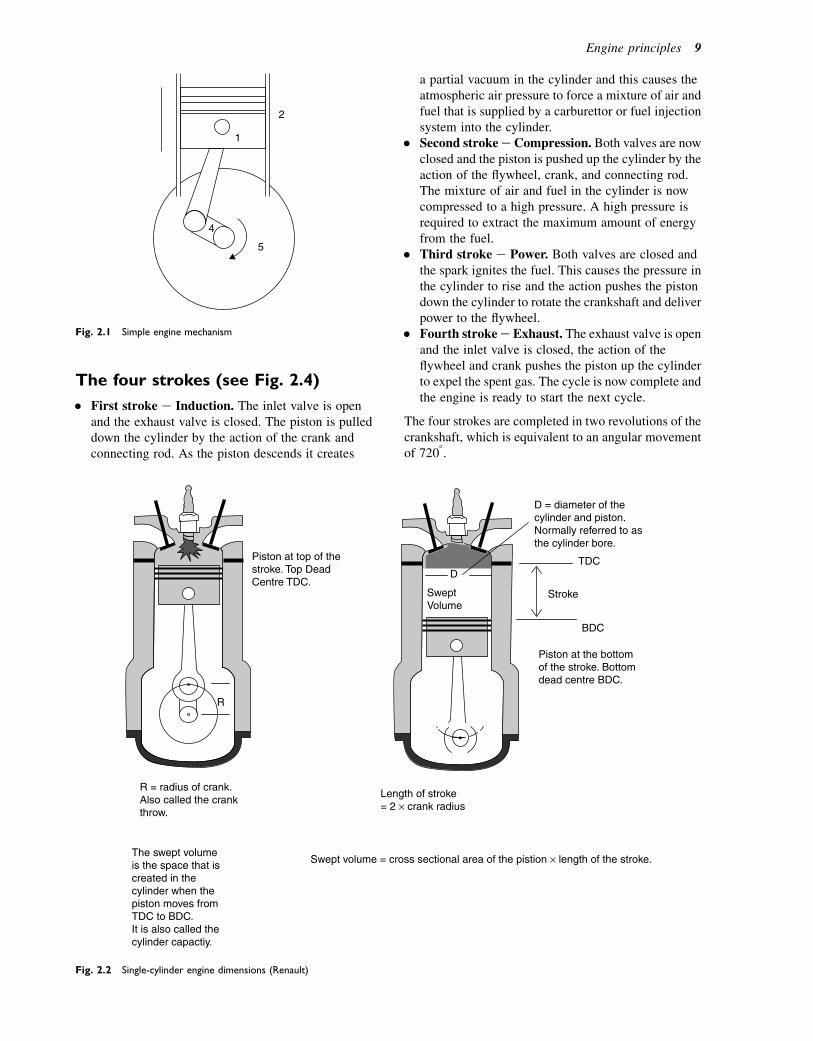
Example of calculating sweptvolume
A single-cylinder engine of the type shown in Fig. 2.2has a bore of 90 mm and a stroke of 100 mm. Calculatethe swept volume in cm3.
Working in centimetres, bore diameter D 5 9 cm,stroke length L 5 10 cm.
The swept volume5 area of piston crown3 stroke length:
The piston crown is a circle and its area
5pD2
45
3:1423 93 9
45 63:6 cm2:
The swept volume5 63:63 105 636 cm3:
A cycle of operations
In order for the engine to function it goes througha sequence of events:
1. Getting air into the cylinder.2. Getting fuel into the cylinder and igniting the
fuel.3. Expanding the high-pressure air to produce useful
work.4. Getting rid of the spent gas so that the sequence can
be repeated.
This sequence of events is called a cycle.
The four-stroke Otto cycle
A large proportion of light vehicle engines use petrol asa fuel and they operate on the Otto cycle. The Otto cycleis named after Dr A. Otto, who developed the firstcommercially successful engines, in Germany, in the1860s. Otto cycle engines are also called four-strokeengines because the Otto cycle takes four strokes ofthe piston for its completion.
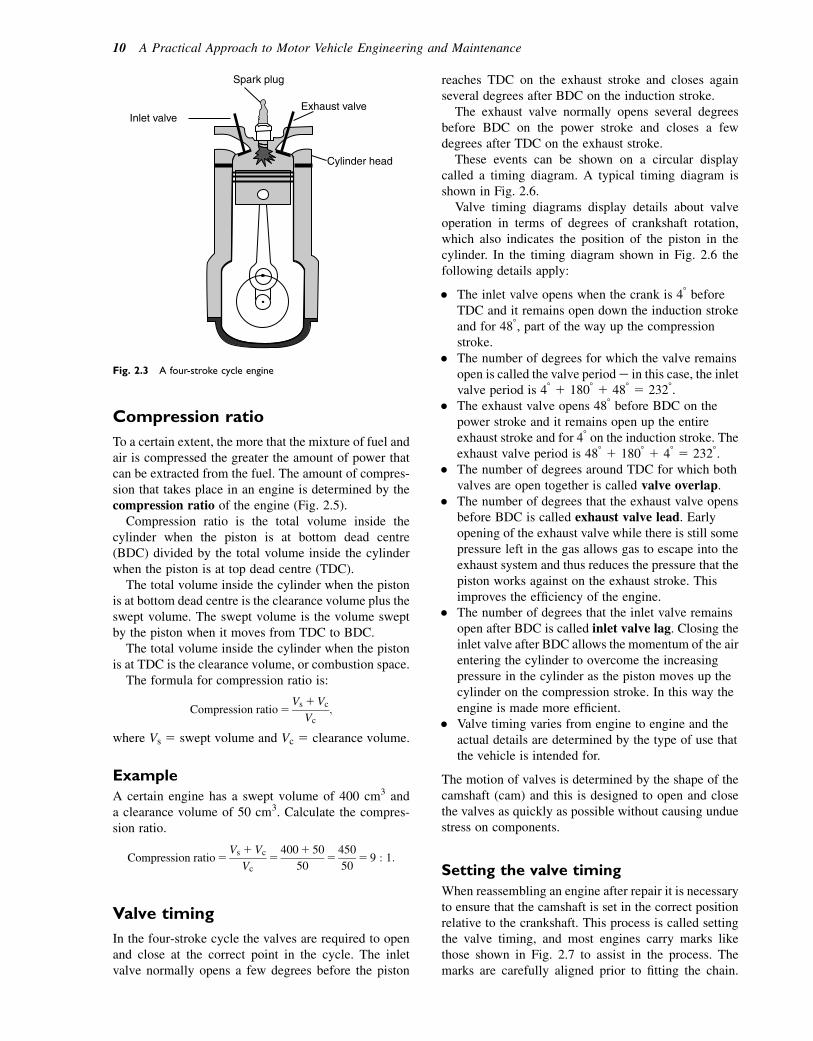
The basic engine
A four-stroke engine (Fig. 2.3) has one end of thecylinder sealed e this end of the cylinder is called thecylinder head. In the cylinder head are two valves anda spark plug that supplies the spark that ignites thefuel. One valve is called the inlet valve and it is openedwhen air and fuel are required; the other valve is theexhaust valve and this is opened when the spent gas isremoved from the cylinder.
� 2011 Allan Bonnick and Derek Newbold. Published by Elsevier Ltd. All rights reserved
The four strokes (see Fig. 2.4)
� First stroke e Induction. The inlet valve is openand the exhaust valve is closed. The piston is pulleddown the cylinder by the action of the crank andconnecting rod. As the piston descends it creates
a partial vacuum in the cylinder and this causes theatmospheric air pressure to force a mixture of air andfuel that is supplied by a carburettor or fuel injectionsystem into the cylinder.
� Second strokee Compression. Both valves are nowclosed and the piston is pushed up the cylinder by theaction of the flywheel, crank, and connecting rod.The mixture of air and fuel in the cylinder is nowcompressed to a high pressure. A high pressure isrequired to extract the maximum amount of energyfrom the fuel.
� Third stroke e Power. Both valves are closed andthe spark ignites the fuel. This causes the pressure inthe cylinder to rise and the action pushes the pistondown the cylinder to rotate the crankshaft and deliverpower to the flywheel.
� Fourth strokee Exhaust. The exhaust valve is openand the inlet valve is closed, the action of theflywheel and crank pushes the piston up the cylinderto expel the spent gas. The cycle is now complete andthe engine is ready to start the next cycle.
The four strokes are completed in two revolutions of thecrankshaft, which is equivalent to an angular movementof 7208.
2
1
5
4
Fig. 2.1 Simple engine mechanism
R
D
SweptVolume
Piston at top of thestroke. Top Dead Centre TDC.
R = radius of crank.Also called the crankthrow.
Length of stroke= 2 × crank radius
D = diameter of thecylinder and piston.Normally referred to asthe cylinder bore.
Stroke
TDC
BDC
Piston at the bottomof the stroke. Bottomdead centre BDC.
The swept volumeis the space that iscreated in the cylinder when thepiston moves fromTDC to BDC.It is also called thecylinder capactiy.
Swept volume = cross sectional area of the pistion × length of the stroke.
Fig. 2.2 Single-cylinder engine dimensions (Renault)
Engine principles 9
Compression ratio
To a certain extent, the more that the mixture of fuel andair is compressed the greater the amount of power thatcan be extracted from the fuel. The amount of compres-sion that takes place in an engine is determined by thecompression ratio of the engine (Fig. 2.5).
Compression ratio is the total volume inside thecylinder when the piston is at bottom dead centre(BDC) divided by the total volume inside the cylinderwhen the piston is at top dead centre (TDC).
The total volume inside the cylinder when the pistonis at bottom dead centre is the clearance volume plus theswept volume. The swept volume is the volume sweptby the piston when it moves from TDC to BDC.
The total volume inside the cylinder when the pistonis at TDC is the clearance volume, or combustion space.
The formula for compression ratio is:
Compression ratio5Vs1Vc
Vc;
where Vs 5 swept volume and Vc 5 clearance volume.
Example
A certain engine has a swept volume of 400 cm3 anda clearance volume of 50 cm3. Calculate the compres-sion ratio.
Compression ratio5Vs 1Vc
Vc5
4001 50
505450
505 9 : 1:
Valve timing
In the four-stroke cycle the valves are required to openand close at the correct point in the cycle. The inletvalve normally opens a few degrees before the piston
reaches TDC on the exhaust stroke and closes againseveral degrees after BDC on the induction stroke.
The exhaust valve normally opens several degreesbefore BDC on the power stroke and closes a fewdegrees after TDC on the exhaust stroke.
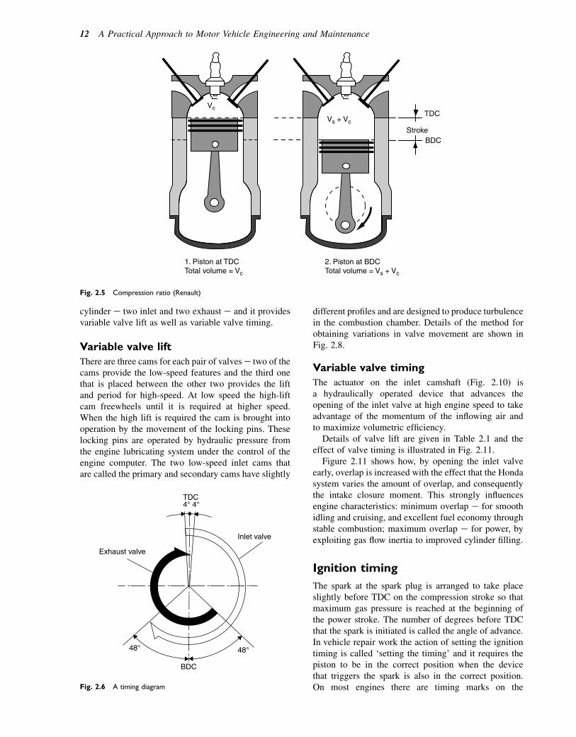
These events can be shown on a circular displaycalled a timing diagram. A typical timing diagram isshown in Fig. 2.6.
Valve timing diagrams display details about valveoperation in terms of degrees of crankshaft rotation,which also indicates the position of the piston in thecylinder. In the timing diagram shown in Fig. 2.6 thefollowing details apply:
� The inlet valve opens when the crank is 48 beforeTDC and it remains open down the induction strokeand for 488, part of the way up the compressionstroke.
� The number of degrees for which the valve remainsopen is called the valve periode in this case, the inletvalve period is 48 1 1808 1 488 5 2328.
� The exhaust valve opens 488 before BDC on thepower stroke and it remains open up the entireexhaust stroke and for 48 on the induction stroke. Theexhaust valve period is 488 1 1808 1 48 5 2328.
� The number of degrees around TDC for which bothvalves are open together is called valve overlap.
� The number of degrees that the exhaust valve opensbefore BDC is called exhaust valve lead. Earlyopening of the exhaust valve while there is still somepressure left in the gas allows gas to escape into theexhaust system and thus reduces the pressure that thepiston works against on the exhaust stroke. Thisimproves the efficiency of the engine.
� The number of degrees that the inlet valve remainsopen after BDC is called inlet valve lag. Closing theinlet valve after BDC allows the momentum of the airentering the cylinder to overcome the increasingpressure in the cylinder as the piston moves up thecylinder on the compression stroke. In this way theengine is made more efficient.
� Valve timing varies from engine to engine and theactual details are determined by the type of use thatthe vehicle is intended for.
The motion of valves is determined by the shape of thecamshaft (cam) and this is designed to open and closethe valves as quickly as possible without causing unduestress on components.
Setting the valve timing
When reassembling an engine after repair it is necessaryto ensure that the camshaft is set in the correct positionrelative to the crankshaft. This process is called settingthe valve timing, and most engines carry marks likethose shown in Fig. 2.7 to assist in the process. Themarks are carefully aligned prior to fitting the chain.
Spark plug
Inlet valveExhaust valve
Cylinder head
Fig. 2.3 A four-stroke cycle engine
10 A Practical Approach to Motor Vehicle Engineering and Maintenance

Engines that use gear or belt drives on the camshaft havesimilar marks.
Valve timing and emissions
When the engine is operating at low speed the overlapthat occurs when the inlet valves and exhaust valvesare open simultaneously is a cause of harmful emissionsand various forms of variable valve control are used to
overcome the problem. Two forms of valve controlthat are used are:
1. Different amounts of valve lift for low and highengine speeds.
2. Automatically changing the valve timing while theengine is running.
The Honda valve system that is outlined here(Fig. 2.8) is used on engines that have four valves per
Fig. 2.4 The Otto cycle of engine operations (four strokes)
Engine principles 11
cylinder e two inlet and two exhaust e and it providesvariable valve lift as well as variable valve timing.
Variable valve lift
There are three cams for each pair of valvese two of thecams provide the low-speed features and the third onethat is placed between the other two provides the liftand period for high-speed. At low speed the high-liftcam freewheels until it is required at higher speed.When the high lift is required the cam is brought intooperation by the movement of the locking pins. Theselocking pins are operated by hydraulic pressure fromthe engine lubricating system under the control of theengine computer. The two low-speed inlet cams thatare called the primary and secondary cams have slightly
different profiles and are designed to produce turbulencein the combustion chamber. Details of the method forobtaining variations in valve movement are shown inFig. 2.8.
Variable valve timing
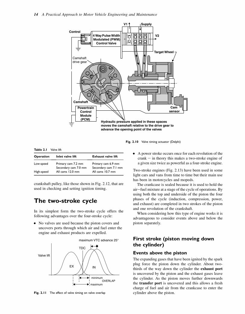
The actuator on the inlet camshaft (Fig. 2.10) isa hydraulically operated device that advances theopening of the inlet valve at high engine speed to takeadvantage of the momentum of the inflowing air andto maximize volumetric efficiency.
Details of valve lift are given in Table 2.1 and theeffect of valve timing is illustrated in Fig. 2.11.
Figure 2.11 shows how, by opening the inlet valveearly, overlap is increased with the effect that the Hondasystem varies the amount of overlap, and consequentlythe intake closure moment. This strongly influencesengine characteristics: minimum overlap e for smoothidling and cruising, and excellent fuel economy throughstable combustion; maximum overlap e for power, byexploiting gas flow inertia to improved cylinder filling.
Ignition timing
The spark at the spark plug is arranged to take placeslightly before TDC on the compression stroke so thatmaximum gas pressure is reached at the beginning ofthe power stroke. The number of degrees before TDCthat the spark is initiated is called the angle of advance.In vehicle repair work the action of setting the ignitiontiming is called ‘setting the timing’ and it requires thepiston to be in the correct position when the devicethat triggers the spark is also in the correct position.On most engines there are timing marks on the
Vc
Vs + VcTDC
StrokeBDC
1. Piston at TDCTotal volume = Vc
2. Piston at BDCTotal volume = Vs + Vc
Fig. 2.5 Compression ratio (Renault)
Exhaust valve
Inlet valve
48°
4° 4°
48°
BDC
TDC
Fig. 2.6 A timing diagram
12 A Practical Approach to Motor Vehicle Engineering and Maintenance
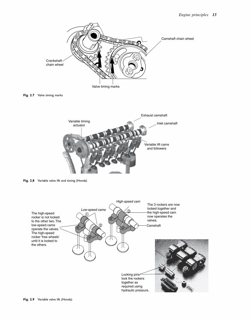
Camshaft chain wheel
Crankshaftchain wheel
Valve timing marks
Fig. 2.7 Valve timing marks
Variable timingactuator
Exhaust camshaft
Inlet camshaft
Variable lift camsand followers
Fig. 2.8 Variable valve lift and timing (Honda)
The 3 rockers are nowlocked together and the high-speed camnow operates the valves.
The high-speedrocker is not lockedto the other two. Thelow-speed camsoperate the valves.The high-speed rocker ‘free wheels’until it is locked to the others.
Locking pinslock the rockerstogether as required usinghydraulic pressure.
Camshaft
Low-speed cams1
3
2
High-speed cam
Fig. 2.9 Variable valve lift (Honda)
Engine principles 13
crankshaft pulley, like those shown in Fig. 2.12, that areused in checking and setting ignition timing.
The two-stroke cycle
In its simplest form the two-stroke cycle offers thefollowing advantages over the four-stroke cycle:
� No valves are used because the piston covers anduncovers ports through which air and fuel enter theengine and exhaust products are expelled.
� A power stroke occurs once for each revolution of thecrank e in theory this makes a two-stroke engine ofa given size twice as powerful as a four-stroke engine.
Two-stroke engines (Fig. 2.13) have been used in somelight cars and vans from time to time but their main usehas been in motorcycles and mopeds.
The crankcase is sealed because it is used to hold theairefuel mixture at a stage of the cycle of operations. Byusing both the top and underside of the piston the fourphases of the cycle (induction, compression, power,and exhaust) are completed in two strokes of the pistonand one revolution of the crankshaft.
When considering how this type of engine works it isadvantageous to consider events above and below thepiston separately.
First stroke (piston moving downthe cylinder)
Events above the piston
The expanding gases that have been ignited by the sparkplug force the piston down the cylinder. About two-thirds of the way down the cylinder the exhaust portis uncovered by the piston and the exhaust gases leavethe cylinder. As the piston moves further downwardsthe transfer port is uncovered and this allows a freshcharge of fuel and air from the crankcase to enter thecylinder above the piston.
Target Wheel
4 Way Pulse WidthModulated (PWM)
Control Valve
Control
Camshaftdrive gear
Camshaft
PowertrainControlModule(PCM)
V1 Supply
V2
Cam sensor
Hydraulic pressure applied in these spacesmoves the camshaft relative to the drive gear toadvance the opening point of the valves
Fig. 2.10 Valve timing actuator (Delphi)
Table 2.1 Valve lift
Operation Inlet valve lift Exhaust valve lift
Low-speed Primary cam 7.2 mm Primary cam 6.9 mm
Secondary cam 7.0 mm Secondary cam 7.1 mm
High-speed All cams 12.0 mm All cams 10.7 mm
Valve lift
TDC
EX IN
maximum VTC advance 25°
maximum OVERLAP
minimum
Fig. 2.11 The effect of valve timing on valve overlap
14 A Practical Approach to Motor Vehicle Engineering and Maintenance
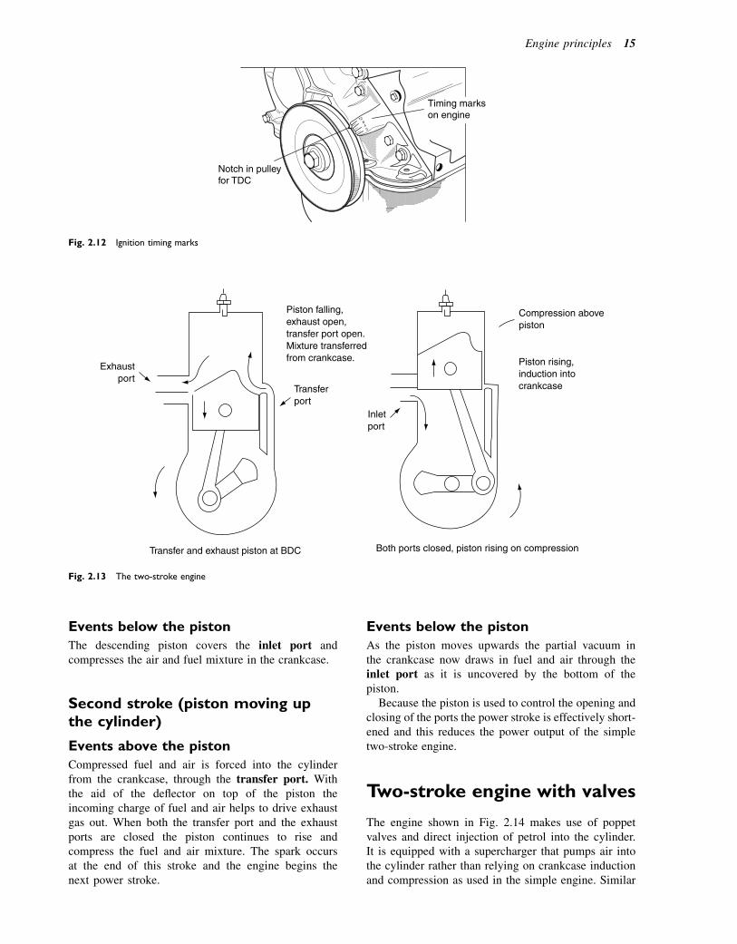
Events below the piston
The descending piston covers the inlet port andcompresses the air and fuel mixture in the crankcase.
Second stroke (piston moving upthe cylinder)
Events above the piston
Compressed fuel and air is forced into the cylinderfrom the crankcase, through the transfer port. Withthe aid of the deflector on top of the piston theincoming charge of fuel and air helps to drive exhaustgas out. When both the transfer port and the exhaustports are closed the piston continues to rise andcompress the fuel and air mixture. The spark occursat the end of this stroke and the engine begins thenext power stroke.
Events below the piston
As the piston moves upwards the partial vacuum inthe crankcase now draws in fuel and air through theinlet port as it is uncovered by the bottom of thepiston.
Because the piston is used to control the opening andclosing of the ports the power stroke is effectively short-ened and this reduces the power output of the simpletwo-stroke engine.
Two-stroke engine with valves
The engine shown in Fig. 2.14 makes use of poppetvalves and direct injection of petrol into the cylinder.It is equipped with a supercharger that pumps air intothe cylinder rather than relying on crankcase inductionand compression as used in the simple engine. Similar
Timing markson engine
Notch in pulleyfor TDC
Fig. 2.12 Ignition timing marks
Exhaustport
Transferport
Transfer and exhaust piston at BDC Both ports closed, piston rising on compression
Piston falling,exhaust open,transfer port open.Mixture transferredfrom crankcase.
Inletport
Compression abovepiston
Piston rising,induction intocrankcase
Fig. 2.13 The two-stroke engine
Engine principles 15
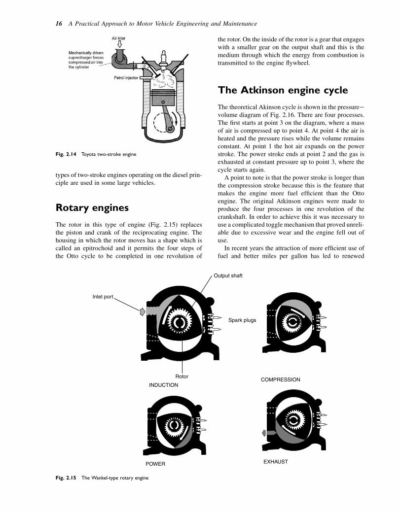
types of two-stroke engines operating on the diesel prin-ciple are used in some large vehicles.
Rotary engines
The rotor in this type of engine (Fig. 2.15) replacesthe piston and crank of the reciprocating engine. Thehousing in which the rotor moves has a shape which iscalled an epitrochoid and it permits the four steps ofthe Otto cycle to be completed in one revolution of
the rotor. On the inside of the rotor is a gear that engageswith a smaller gear on the output shaft and this is themedium through which the energy from combustion istransmitted to the engine flywheel.
The Atkinson engine cycle
The theoretical Akinson cycle is shown in the pressureevolume diagram of Fig. 2.16. There are four processes.The first starts at point 3 on the diagram, where a massof air is compressed up to point 4. At point 4 the air isheated and the pressure rises while the volume remainsconstant. At point 1 the hot air expands on the powerstroke. The power stroke ends at point 2 and the gas isexhausted at constant pressure up to point 3, where thecycle starts again.
A point to note is that the power stroke is longer thanthe compression stroke because this is the feature thatmakes the engine more fuel efficient than the Ottoengine. The original Atkinson engines were made toproduce the four processes in one revolution of thecrankshaft. In order to achieve this it was necessary touse a complicated toggle mechanism that proved unreli-able due to excessive wear and the engine fell out ofuse.
In recent years the attraction of more efficient use offuel and better miles per gallon has led to renewed
Fig. 2.14 Toyota two-stroke engine
Output shaft
Inlet port
Rotor
INDUCTIONCOMPRESSION
Spark plugs
EXHAUSTPOWER
Fig. 2.15 The Wankel-type rotary engine
16 A Practical Approach to Motor Vehicle Engineering and Maintenance
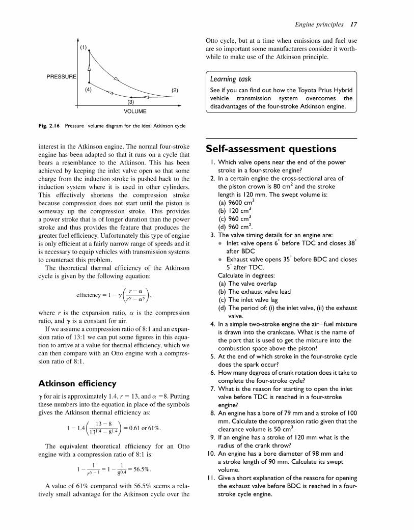
interest in the Atkinson engine. The normal four-strokeengine has been adapted so that it runs on a cycle thatbears a resemblance to the Atkinson. This has beenachieved by keeping the inlet valve open so that somecharge from the induction stroke is pushed back to theinduction system where it is used in other cylinders.This effectively shortens the compression strokebecause compression does not start until the piston issomeway up the compression stroke. This providesa power stroke that is of longer duration than the powerstroke and thus provides the feature that produces thegreater fuel efficiency. Unfortunately this type of engineis only efficient at a fairly narrow range of speeds and itis necessary to equip vehicles with transmission systemsto counteract this problem.
The theoretical thermal efficiency of the Atkinsoncycle is given by the following equation:
efficiency5 12 g
�r2a
rg 2ag
�;
where r is the expansion ratio, a is the compressionratio, and g is a constant for air.
If we assume a compression ratio of 8:1 and an expan-sion ratio of 13:1 we can put some figures in this equa-tion to arrive at a value for thermal efficiency, which wecan then compare with an Otto engine with a compres-sion ratio of 8:1.
Atkinson efficiency
g for air is approximately 1.4, r5 13, and a58. Puttingthese numbers into the equation in place of the symbolsgives the Atkinson thermal efficiency as:
12 1:4
�132 8
131:4 2 81:4
�5 0:61 or 61%:
The equivalent theoretical efficiency for an Ottoengine with a compression ratio of 8:1 is:
121
rg2 15 12
1
80:45 56:5%:
A value of 61% compared with 56.5% seems a rela-tively small advantage for the Atkinson cycle over the
Otto cycle, but at a time when emissions and fuel useare so important some manufacturers consider it worth-while to make use of the Atkinson principle.
Learning task
See if you can find out how the Toyota Prius Hybridvehicle transmission system overcomes thedisadvantages of the four-stroke Atkinson engine.
Self-assessment questions1. Which valve opens near the end of the power
stroke in a four-stroke engine?2. In a certain engine the cross-sectional area of
the piston crown is 80 cm2 and the strokelength is 120 mm. The swept volume is:(a) 9600 cm3
(b) 120 cm3
(c) 960 cm3
(d) 960 cm2.3. The valve timing details for an engine are:
� Inlet valve opens 68 before TDC and closes 388
after BDC� Exhaust valve opens 358 before BDC and closes
58 after TDC.Calculate in degrees:(a) The valve overlap(b) The exhaust valve lead(c) The inlet valve lag(d) The period of: (i) the inlet valve, (ii) the exhaust
valve.4. In a simple two-stroke engine the airefuel mixture
is drawn into the crankcase. What is the name ofthe port that is used to get the mixture into thecombustion space above the piston?
5. At the end of which stroke in the four-stroke cycledoes the spark occur?
6. How many degrees of crank rotation does it take tocomplete the four-stroke cycle?
7. What is the reason for starting to open the inletvalve before TDC is reached in a four-strokeengine?
8. An engine has a bore of 79 mm and a stroke of 100mm. Calculate the compression ratio given that theclearance volume is 50 cm3.
9. If an engine has a stroke of 120 mm what is theradius of the crank throw?
10. An engine has a bore diameter of 98 mm anda stroke length of 90 mm. Calculate its sweptvolume.
11. Give a short explanation of the reasons for openingthe exhaust valve before BDC is reached in a four-stroke cycle engine.
(1)
(2)
(3)
VOLUME
PRESSURE
(4)
Fig. 2.16 Pressureevolume diagram for the ideal Atkinson cycle
Engine principles 17

12. Figure 2.17 shows two valve timing diagrams.Which of these would be suitable for a high-speedengine?
Questions 13e16 relate to the Honda system.
13. 258 of camshaft advance is equal to:(a) 508 of crankshaft rotation(b) 1008 of crankshaft rotation(c) 12.58 of crankshaft rotation(d) 258 of crankshaft rotation.
14. What effect on the closing point of the inlet valve isbrought about by opening it 258 early?
15. The maximum lift of the inlet valve is:(a) 7.2 mm(b) 6.9 mm(c) 12.0 mm(d) 10.7 mm.
16. The difference in lift between the inlet primary andsecondary cams at low speed is:(a) 4.8 mm(b) 5 mm(c) 0.20 mm(d) 0.30 mm.
17. Discuss with other students vehicles (other thanthe Trabant and motor cycles) that have been fittedwith two-stoke engines in recent years.
18. With the aid of diagrams describe how theclearance volume of an engine can be measured andthen describe how knowledge of the bore andstroke would enable you to work out thecompression ratio.
19. Make a list of the vehicles equipped with a Wankel-type rotary engine that are currently available in theUK.
Fig. 2.17 Typical value timing diagrams
18 A Practical Approach to Motor Vehicle Engineering and Maintenance
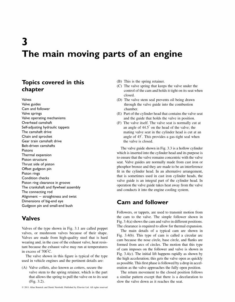
3The main moving parts of an engine
Topics covered in thischapter
ValvesValve guidesCam and followerValve springsValve operating mechanismsOverhead camshaftSelf-adjusting hydraulic tappetsThe camshaft driveChain and sprocketGear train camshaft driveBelt-driven camshaftsPistonsThermal expansionPiston structureThrust side of pistonOffset gudgeon pinPiston ringsCondition checksPiston ring clearance in grooveThe crankshaft and flywheel assemblyThe connecting rodAlignment e straightness and twistDimensions of big-end eyeGudgeon pin and small-end bush
Valves
Valves of the type shown in Fig. 3.1 are called poppetvalves, or mushroom valves because of their shape.Valves are made from high-quality steel that is hardwearing and, in the case of the exhaust valve, heat resis-tant because the exhaust valve may run at temperaturesin excess of 7008C.The valve shown in this figure is typical of the type
used in vehicle engines and the pertinent details are:
(A) Valve collets, also known as cotters, secure thevalve stem to the spring retainer, which is the partthat allows the spring to pull the valve on to its seat(Fig. 3.2).
(B) This is the spring retainer.(C) The valve spring that keeps the valve under the
control of the cam and holds it tight on its seat whenclosed.
(D) The valve stem seal prevents oil being drawnthrough the valve guide into the combustionchamber.
(E) Part of the cylinder head that contains the valve seatand the guide that holds the valve in position.
(F) The valve itself. The valve seat is normally cut atan angle of 44.58 on the head of the valve; themating valve seat in the cylinder head is cut at anangle of 458. This provides a gas-tight seal whenthe valve is closed.
The valve guide shown in Fig. 3.3 is a hollow cylinderwhich is inserted into the cylinder head and its purpose isto ensure that the valve remains concentric with the valveseat. Valve guides are normally made from cast iron orphosphor bronze and they are made to be an interferencefit in the cylinder head. In an alternative arrangement,that is sometimes used in cast iron cylinder heads, thevalve guide is an integral part of the cylinder head. Inoperation the valve guide takes heat away from the valveand conducts it into the engine cooling system.
Cam and follower
Followers, or tappets, are used to transmit motion fromthe cam to the valve. The simple follower shown inFig. 3.4(a) shows the cam and valve in different positions.The clearance is required to allow for thermal expansion.
The main details of a typical cam are shown inFig. 3.4(b). This type of cam is called a circular arccam because the nose circle, base circle, and flanks areformed from arcs of circles. The motion that this typeof cam imposes on the follower and valve is shown inFig. 3.4(c). The initial lift happens rapidly as shown bythe high acceleration; this gets the valve open as quicklyas possible. This first phase is followed by a drop in accel-eration as the valve approaches the fully open position.
The return movement to the closed position followsa similar pattern except that there is a decelaration toslow the valve down as it reaches the seat.
� 2011 Allan Bonnick and Derek Newbold. Published by Elsevier Ltd. All rights reserved
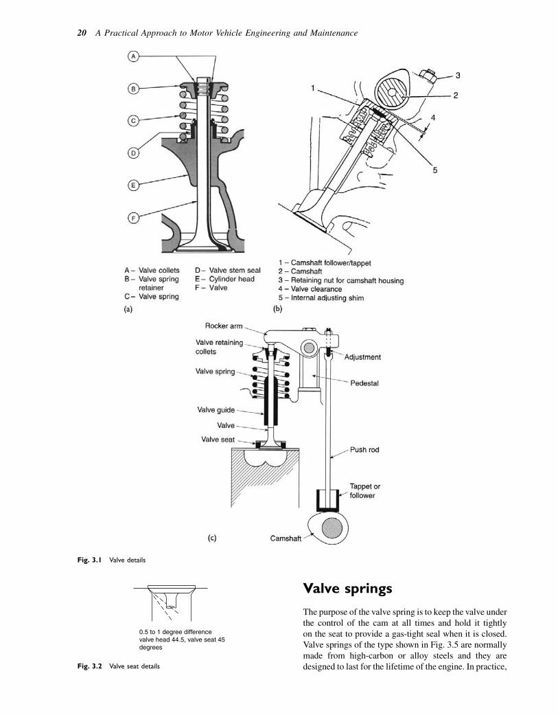
Valve springs
The purpose of the valve spring is to keep the valve underthe control of the cam at all times and hold it tightlyon the seat to provide a gas-tight seal when it is closed.Valve springs of the type shown in Fig. 3.5 are normallymade from high-carbon or alloy steels and they aredesigned to last for the lifetime of the engine. In practice,
Fig. 3.1 Valve details
0.5 to 1 degree differencevalve head 44.5, valve seat 45degrees
Fig. 3.2 Valve seat details
20 A Practical Approach to Motor Vehicle Engineering and Maintenance
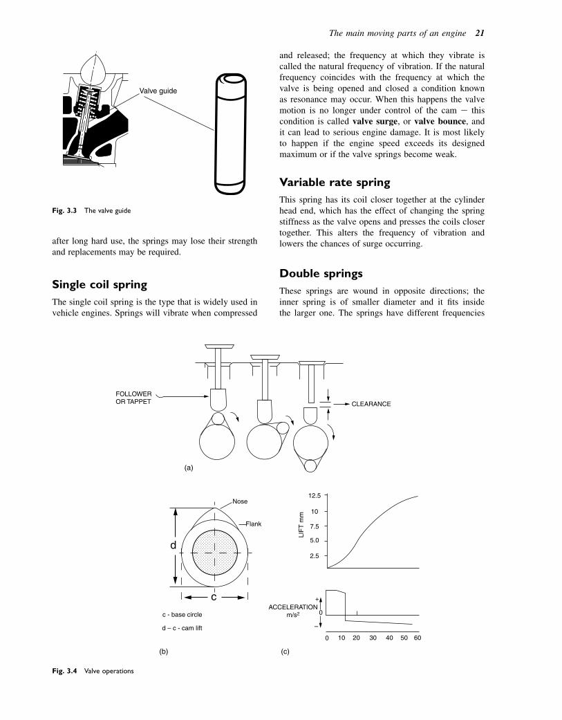
after long hard use, the springs may lose their strengthand replacements may be required.
Single coil spring
The single coil spring is the type that is widely used invehicle engines. Springs will vibrate when compressed
and released; the frequency at which they vibrate iscalled the natural frequency of vibration. If the naturalfrequency coincides with the frequency at which thevalve is being opened and closed a condition knownas resonance may occur. When this happens the valvemotion is no longer under control of the cam e thiscondition is called valve surge, or valve bounce, andit can lead to serious engine damage. It is most likelyto happen if the engine speed exceeds its designedmaximum or if the valve springs become weak.
Variable rate spring
This spring has its coil closer together at the cylinderhead end, which has the effect of changing the springstiffness as the valve opens and presses the coils closertogether. This alters the frequency of vibration andlowers the chances of surge occurring.
Double springs
These springs are wound in opposite directions; theinner spring is of smaller diameter and it fits insidethe larger one. The springs have different frequencies
Valve guide
Fig. 3.3 The valve guide
(a)
12.5
10
7.5
LIF
T m
m
Nose
CLEARANCE
ACCELERATIONm/s2
FOLLOWEROR TAPPET
Flank
c - base circle
d – c - cam lift
5.0
2.5
0
0 10 20 30 40 50 60
(b) (c)
d
c +
–
Fig. 3.4 Valve operations
The main moving parts of an engine 21

of vibration and it is believed that this reduces the possi-bility of valve bounce.
Valve operating mechanisms
In the overhead valve (OHV) operating mechanismshown in Fig. 3.6, the camshaft is driven from the enginecrankshaft at half crankshaft speed and cam motion istransferred through the tappet and push rod to the rockerarm. The rocker arm is a simple lever that then pusheson the end of the valve stem to open the valve againstthe action of the spring. As the camshaft rotates furtherthe cam allows the tappet and push rod to drop backwhile the valve spring returns the valve to its seat. The
valve clearance may be altered by means of the adjust-ment screw and lock nut at the push rod end of therocker arm.
Overhead camshaft
In the overhead camshaft (OHC) arrangement shown inFig. 3.7, the camshaft is mounted in the cylinder head.An advantage of this system is that fewer parts arerequired to transmit cam motion to the valve. However,it does require an abundant supply of oil so the camchamber and cover is of more elaborate design than thesimple OHV alternative. In the design shown, the valve
Outer springInner spring
Single coilspring
Variable ratespring
Two springsone inside the other
Fig. 3.5 Types of valve springs
Rocker arm
Adjustment
Pedestal
Push rod
Tappet orfollower
Camshaft
Valve soat
Valve
Valve guide
Valve spring
Valve retainingcollets
Fig. 3.6 A push-rod-operated valve mechanism e overhead valve
1
3
2
4
5
1 – Camshaft follower/tappet2 – Camshaft3 – Retaining nut for camshaft housing4 – Valve clearance5 – Internal adjusting shim
Fig. 3.7 An overhead camshaft arrangement
22 A Practical Approach to Motor Vehicle Engineering and Maintenance
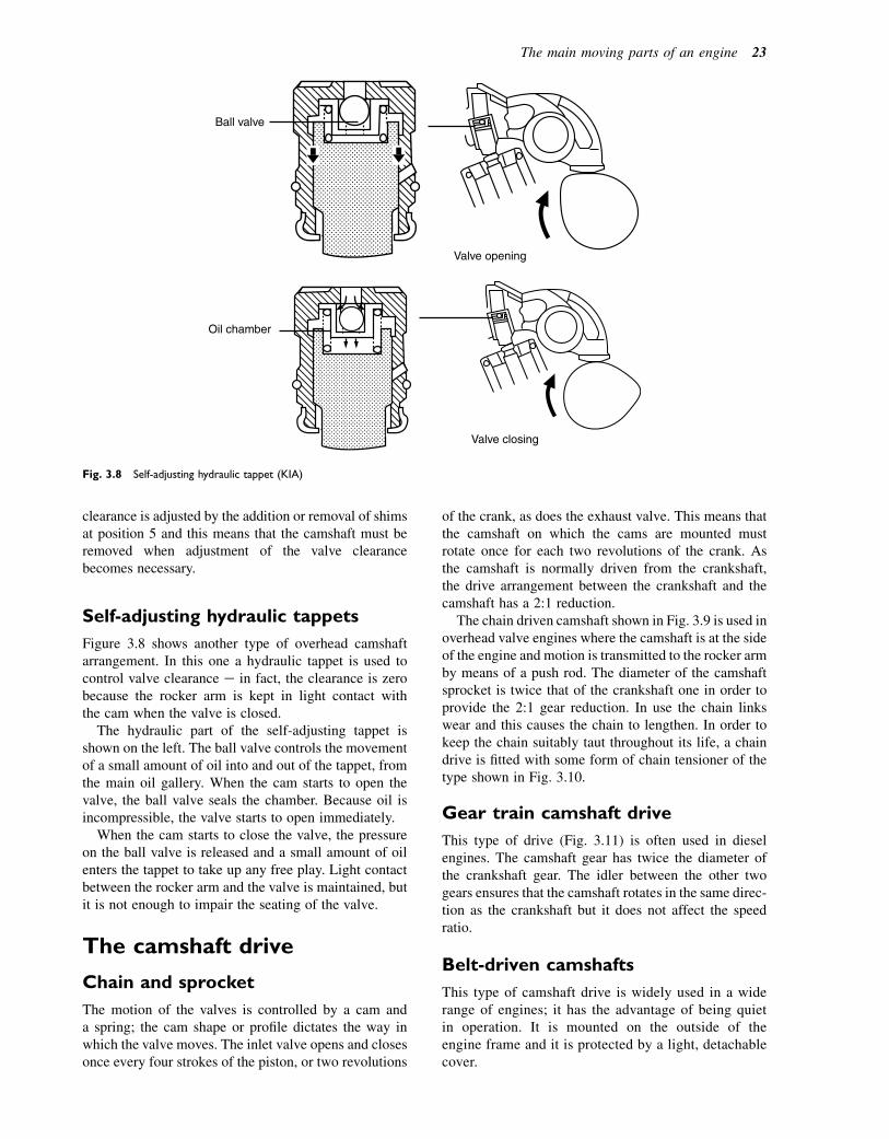
clearance is adjusted by the addition or removal of shimsat position 5 and this means that the camshaft must beremoved when adjustment of the valve clearancebecomes necessary.
Self-adjusting hydraulic tappets
Figure 3.8 shows another type of overhead camshaftarrangement. In this one a hydraulic tappet is used tocontrol valve clearance e in fact, the clearance is zerobecause the rocker arm is kept in light contact withthe cam when the valve is closed.
The hydraulic part of the self-adjusting tappet isshown on the left. The ball valve controls the movementof a small amount of oil into and out of the tappet, fromthe main oil gallery. When the cam starts to open thevalve, the ball valve seals the chamber. Because oil isincompressible, the valve starts to open immediately.
When the cam starts to close the valve, the pressureon the ball valve is released and a small amount of oilenters the tappet to take up any free play. Light contactbetween the rocker arm and the valve is maintained, butit is not enough to impair the seating of the valve.
The camshaft drive
Chain and sprocket
The motion of the valves is controlled by a cam anda spring; the cam shape or profile dictates the way inwhich the valve moves. The inlet valve opens and closesonce every four strokes of the piston, or two revolutions
of the crank, as does the exhaust valve. This means thatthe camshaft on which the cams are mounted mustrotate once for each two revolutions of the crank. Asthe camshaft is normally driven from the crankshaft,the drive arrangement between the crankshaft and thecamshaft has a 2:1 reduction.
The chain driven camshaft shown in Fig. 3.9 is used inoverhead valve engines where the camshaft is at the sideof the engine and motion is transmitted to the rocker armby means of a push rod. The diameter of the camshaftsprocket is twice that of the crankshaft one in order toprovide the 2:1 gear reduction. In use the chain linkswear and this causes the chain to lengthen. In order tokeep the chain suitably taut throughout its life, a chaindrive is fitted with some form of chain tensioner of thetype shown in Fig. 3.10.
Gear train camshaft drive
This type of drive (Fig. 3.11) is often used in dieselengines. The camshaft gear has twice the diameter ofthe crankshaft gear. The idler between the other twogears ensures that the camshaft rotates in the same direc-tion as the crankshaft but it does not affect the speedratio.
Belt-driven camshafts
This type of camshaft drive is widely used in a widerange of engines; it has the advantage of being quietin operation. It is mounted on the outside of theengine frame and it is protected by a light, detachablecover.
Ball valve
Valve opening
Oil chamber
Valve closing
Fig. 3.8 Self-adjusting hydraulic tappet (KIA)
The main moving parts of an engine 23
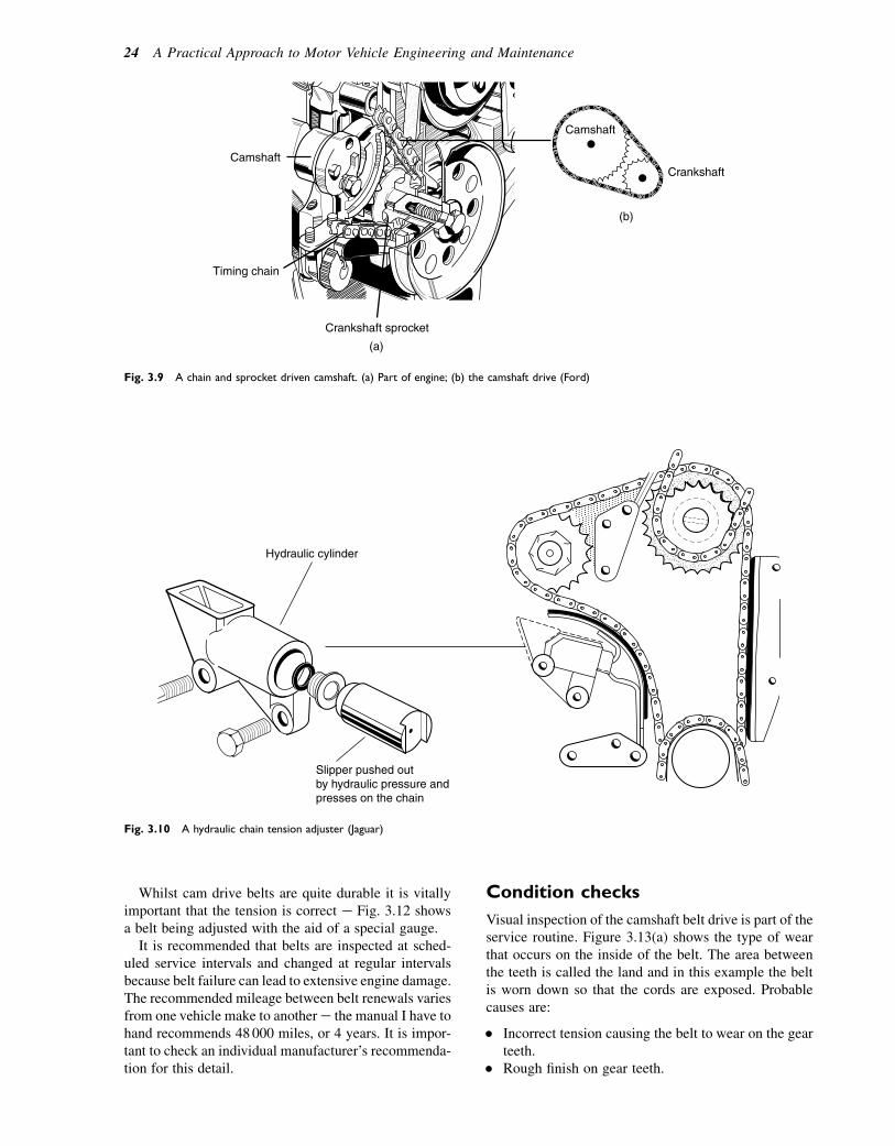
Whilst cam drive belts are quite durable it is vitallyimportant that the tension is correct e Fig. 3.12 showsa belt being adjusted with the aid of a special gauge.
It is recommended that belts are inspected at sched-uled service intervals and changed at regular intervalsbecause belt failure can lead to extensive engine damage.The recommended mileage between belt renewals variesfrom one vehicle make to anothere the manual I have tohand recommends 48000 miles, or 4 years. It is impor-tant to check an individual manufacturer’s recommenda-tion for this detail.
Condition checks
Visual inspection of the camshaft belt drive is part of theservice routine. Figure 3.13(a) shows the type of wearthat occurs on the inside of the belt. The area betweenthe teeth is called the land and in this example the beltis worn down so that the cords are exposed. Probablecauses are:
� Incorrect tension causing the belt to wear on the gearteeth.
� Rough finish on gear teeth.
Camshaft
Crankshaft
Crankshaft sprocket
(b)
(a)
Camshaft
Timing chain
Fig. 3.9 A chain and sprocket driven camshaft. (a) Part of engine; (b) the camshaft drive (Ford)
Hydraulic cylinder
Slipper pushed outby hydraulic pressure andpresses on the chain
Fig. 3.10 A hydraulic chain tension adjuster (Jaguar)
24 A Practical Approach to Motor Vehicle Engineering and Maintenance

Figure 3.13(b) shows the type of damage that iscaused by low belt tension. This allows the belt to rideup on the gear teeth and causes wear on the thrustface of the belt teeth. In both cases the belt wouldrequire replacement.
Pistons
When the piston is at top dead centre (TDC) it acts aspart of the combustion chamber; after combustion hastaken place the gas force generated is transmitted fromthe piston, through the gudgeon pin and connectingrod to the crankshaft. Most automotive pistons aremade from aluminium alloy, which has the followingproperties:
1. It is lighter than steel or cast iron.2. It has good heat conductivity.
3. It has good strength and is reasonably resistant towear.
4. It has a higher thermal expansion coefficient than thecast iron cylinder in which it works.
The high thermal expansion coefficient of aluminiumalloy has a considerable effect on the design ofpistons, which is a factor that is now considered insome detail.
The piston crown
Melting temperature
Aluminium alloy melts at approximately 5208C and thetemperature in the combustion chamber may be as highas 16008C. This is not normally a problem because ofthe high thermal conductivity of aluminium (Al) alloy,and the fact that the piston is only in contact with high
Idler gear
Crankshaft gear
Camshaft gear
Fig. 3.11 Gear train camshaft drive (Rover)
5
3
4
76
2
1
Facing fabric:an elastic nylonfacing. Low frictionand hard wearing.
Rubber stock: mouldedand cured around the cords and facing fabric.
Tension memberfibre glass cordwound round belt
Fig. 3.12 Belt drive camshaft and belt tension (Rover). (1) Camshaft gear. (2) Timing belt. (3) Timing belt tensioner. (4) Reference line on engine.
(5) Crankshaft gear. (6) Link for attaching spring balance. (7) Spring balance
The main moving parts of an engine 25

temperature for a short while; the working temperatureof the piston crown is normally between 200 and3008C. Figure 3.15 shows the approximate range oftemperature along the length of the piston.
Thermal expansion
The coefficient of thermal expansion of Al alloy isapproximately 0.000023 per 8C, while that of the cast
iron cylinder in which the piston works is approximately0.000011 per 8C. To allow for this difference the pistondiameter is made to be smaller than the cylinder diam-eter, when cold. When the piston and cylinder are atworking temperature the gap between them is decreasedby the greater amount of piston expansion that occurs inthe Al alloy.
Piston structure
The mechanical stress on the piston is greatest at thecrown and in the region of the gudgeon pin, and a greatervolume of metal is concentrated in these areas toprovide the extra strength that is required. This meansthat the thermal expansion is greater in some regionsof the piston than it is in others and pistons are designedto allow for it, as shown in Fig. 3.16.
The parts of the piston between the ring grooves arecalled the lands. The top land at the crown of the pistonoperates at the highest temperature and the diameter E isconsiderably smaller than the cylinder bore diameter toallow for expansion.
The piston diameter C as measured at the bottom ofthe piston, on the skirt at right angles to the gudgeonpin holes, is greater than the diameter E at the top,and the piston is effectively tapered along its length.
D is the diameter of the piston as measured on theskirt, just below the gudgeon pin holes, and it is smallerthan the diameter C to allow for extra expansion causedby the additional metal at the gudgeon pin bosses. Thediameter C is the largest diameter on the piston and itis considerably greater than D, which means that thepiston has an oval shape on its skirt.
The diameter C is taken as the piston diameter whenpistons are being measured to check for clearancein the cylinder. As a general guide it is recommendedthat the clearance between the piston skirt and thecylinder should be between 0.001 and 0.002 timesthe diameter; a manual that I am referring to specifiesa clearance of 0.12 mm on a cylinder diameter of
Crown
Ringbelt
Skirt
Gudgeon pin boss andhole
Fig. 3.14 Piston details (Toyota)
300° C
220° C
150° C
B
Fig. 3.15 Approximate piston operating temperatures
Fig. 3.13 Cam belt wear
26 A Practical Approach to Motor Vehicle Engineering and Maintenance
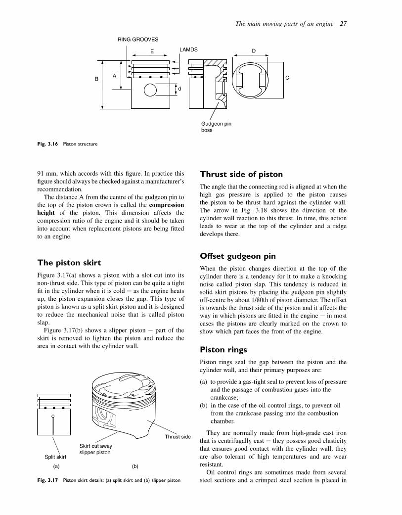
91 mm, which accords with this figure. In practice thisfigure should always be checked against a manufacturer’srecommendation.
The distance A from the centre of the gudgeon pin tothe top of the piston crown is called the compressionheight of the piston. This dimension affects thecompression ratio of the engine and it should be takeninto account when replacement pistons are being fittedto an engine.
The piston skirt
Figure 3.17(a) shows a piston with a slot cut into itsnon-thrust side. This type of piston can be quite a tightfit in the cylinder when it is cold e as the engine heatsup, the piston expansion closes the gap. This type ofpiston is known as a split skirt piston and it is designedto reduce the mechanical noise that is called pistonslap.
Figure 3.17(b) shows a slipper piston e part of theskirt is removed to lighten the piston and reduce thearea in contact with the cylinder wall.
Thrust side of piston
The angle that the connecting rod is aligned at when thehigh gas pressure is applied to the piston causesthe piston to be thrust hard against the cylinder wall.The arrow in Fig. 3.18 shows the direction of thecylinder wall reaction to this thrust. In time, this actionleads to wear at the top of the cylinder and a ridgedevelops there.
Offset gudgeon pin
When the piston changes direction at the top of thecylinder there is a tendency for it to make a knockingnoise called piston slap. This tendency is reduced insolid skirt pistons by placing the gudgeon pin slightlyoff-centre by about 1/80th of piston diameter. The offsetis towards the thrust side of the piston and it affects theway in which pistons are fitted in the engine e in mostcases the pistons are clearly marked on the crown toshow which part faces the front of the engine.
Piston rings
Piston rings seal the gap between the piston and thecylinder wall, and their primary purposes are:
(a) to provide a gas-tight seal to prevent loss of pressureand the passage of combustion gases into thecrankcase;
(b) in the case of the oil control rings, to prevent oilfrom the crankcase passing into the combustionchamber.
They are normally made from high-grade cast ironthat is centrifugally cast e they possess good elasticitythat ensures good contact with the cylinder wall, theyare also tolerant of high temperatures and are wearresistant.
Oil control rings are sometimes made from severalsteel sections and a crimped steel section is placed in
(a)
Split skirt
Skirt cut awayslipper piston
Thrust side
(b)
Fig. 3.17 Piston skirt details: (a) split skirt and (b) slipper piston
Gudgeon pinboss
LAMDS
RING GROOVES
AB
E
d
D
C
Fig. 3.16 Piston structure
The main moving parts of an engine 27
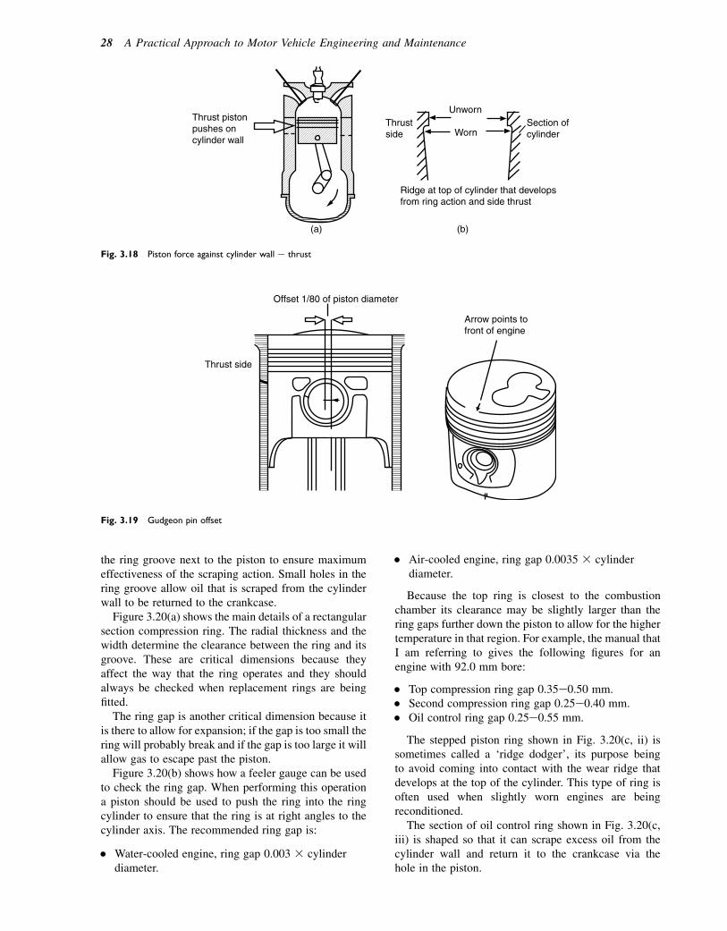
the ring groove next to the piston to ensure maximumeffectiveness of the scraping action. Small holes in thering groove allow oil that is scraped from the cylinderwall to be returned to the crankcase.
Figure 3.20(a) shows the main details of a rectangularsection compression ring. The radial thickness and thewidth determine the clearance between the ring and itsgroove. These are critical dimensions because theyaffect the way that the ring operates and they shouldalways be checked when replacement rings are beingfitted.
The ring gap is another critical dimension because itis there to allow for expansion; if the gap is too small thering will probably break and if the gap is too large it willallow gas to escape past the piston.
Figure 3.20(b) shows how a feeler gauge can be usedto check the ring gap. When performing this operationa piston should be used to push the ring into the ringcylinder to ensure that the ring is at right angles to thecylinder axis. The recommended ring gap is:
� Water-cooled engine, ring gap 0.003 3 cylinderdiameter.
� Air-cooled engine, ring gap 0.0035 3 cylinderdiameter.
Because the top ring is closest to the combustionchamber its clearance may be slightly larger than thering gaps further down the piston to allow for the highertemperature in that region. For example, the manual thatI am referring to gives the following figures for anengine with 92.0 mm bore:
� Top compression ring gap 0.35e0.50 mm.� Second compression ring gap 0.25e0.40 mm.� Oil control ring gap 0.25e0.55 mm.
The stepped piston ring shown in Fig. 3.20(c, ii) issometimes called a ‘ridge dodger’, its purpose beingto avoid coming into contact with the wear ridge thatdevelops at the top of the cylinder. This type of ring isoften used when slightly worn engines are beingreconditioned.
The section of oil control ring shown in Fig. 3.20(c,iii) is shaped so that it can scrape excess oil from thecylinder wall and return it to the crankcase via thehole in the piston.
Unworn
WornThrustside
Section ofcylinder
Thrust pistonpushes oncylinder wall
(a) (b)
Ridge at top of cylinder that developsfrom ring action and side thrust
Fig. 3.18 Piston force against cylinder wall e thrust
Thrust side
Offset 1/80 of piston diameter
Arrow points tofront of engine
Fig. 3.19 Gudgeon pin offset
28 A Practical Approach to Motor Vehicle Engineering and Maintenance
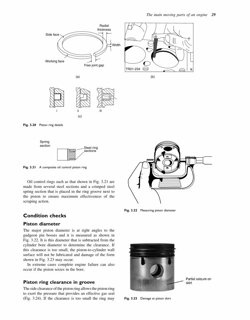
Oil control rings such as that shown in Fig. 3.21 aremade from several steel sections and a crimped steelspring section that is placed in the ring groove next tothe piston to ensure maximum effectiveness of thescraping action.
Condition checks
Piston diameter
The major piston diameter is at right angles to thegudgeon pin bosses and it is measured as shown inFig. 3.22. It is this diameter that is subtracted from thecylinder bore diameter to determine the clearance. Ifthis clearance is too small, the piston-to-cylinder wallsurface will not be lubricated and damage of the formshown in Fig. 3.23 may occur.
In extreme cases complete engine failure can alsooccur if the piston seizes in the bore.
Piston ring clearance in groove
The side clearance of the piston ring allows the piston ringto exert the pressure that provides an effective gas seal(Fig. 3.24). If the clearance is too small the ring may
KTR21-234
(b)(a)
(c)
Width
Radialthickness
Free joint gap
Side face
Working face
i ii iii
Fig. 3.20 Piston ring details
Springsection
Steel ringsections
Fig. 3.21 A composite oil control piston ring
Fig. 3.22 Measuring piston diameter
Fig. 3.23 Damage at piston skirt
The main moving parts of an engine 29
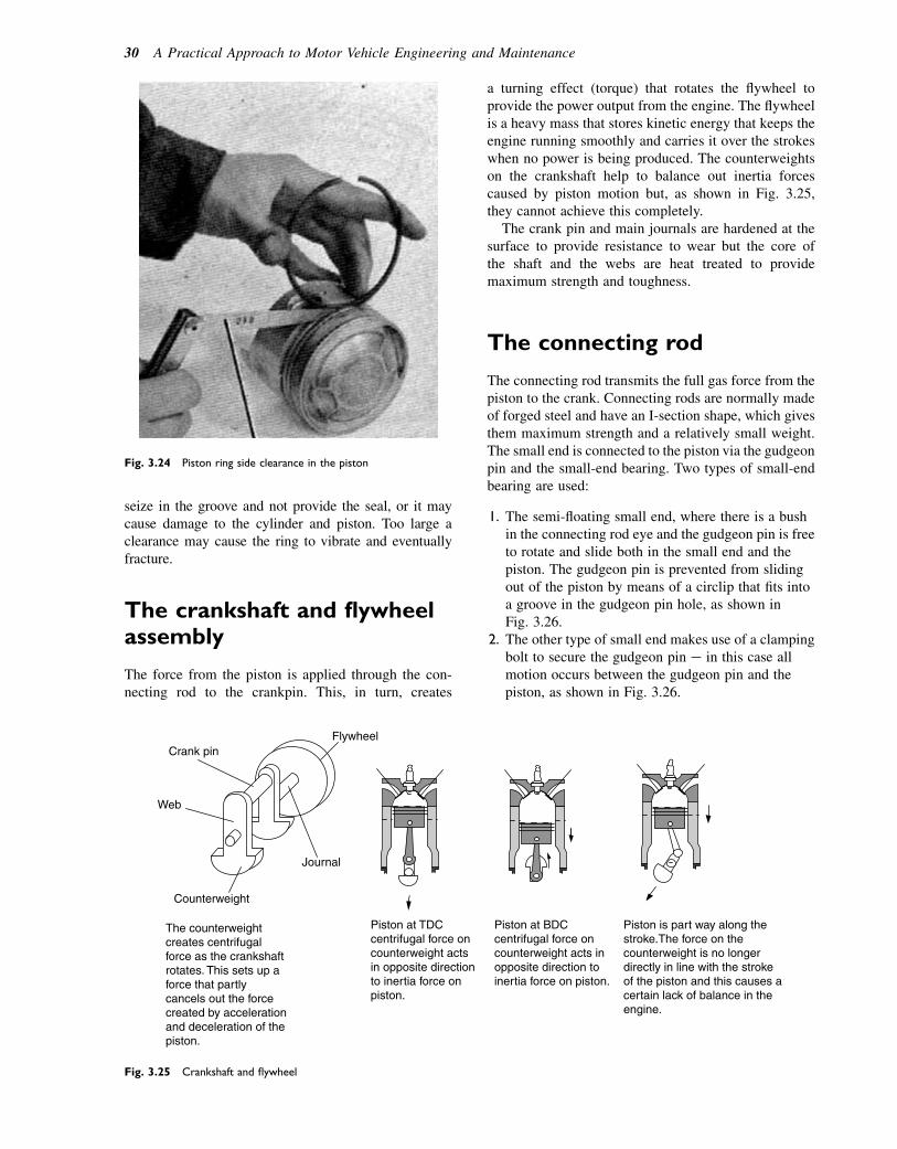
seize in the groove and not provide the seal, or it maycause damage to the cylinder and piston. Too large aclearance may cause the ring to vibrate and eventuallyfracture.
The crankshaft and flywheelassembly
The force from the piston is applied through the con-necting rod to the crankpin. This, in turn, creates
a turning effect (torque) that rotates the flywheel toprovide the power output from the engine. The flywheelis a heavy mass that stores kinetic energy that keeps theengine running smoothly and carries it over the strokeswhen no power is being produced. The counterweightson the crankshaft help to balance out inertia forcescaused by piston motion but, as shown in Fig. 3.25,they cannot achieve this completely.
The crank pin and main journals are hardened at thesurface to provide resistance to wear but the core ofthe shaft and the webs are heat treated to providemaximum strength and toughness.
The connecting rod
The connecting rod transmits the full gas force from thepiston to the crank. Connecting rods are normally madeof forged steel and have an I-section shape, which givesthem maximum strength and a relatively small weight.The small end is connected to the piston via the gudgeonpin and the small-end bearing. Two types of small-endbearing are used:
1. The semi-floating small end, where there is a bushin the connecting rod eye and the gudgeon pin is freeto rotate and slide both in the small end and thepiston. The gudgeon pin is prevented from slidingout of the piston by means of a circlip that fits intoa groove in the gudgeon pin hole, as shown inFig. 3.26.
2. The other type of small end makes use of a clampingbolt to secure the gudgeon pin e in this case allmotion occurs between the gudgeon pin and thepiston, as shown in Fig. 3.26.
Fig. 3.24 Piston ring side clearance in the piston
FlywheelCrank pin
Web
Journal
Counterweight
The counterweightcreates centrifugalforce as the crankshaftrotates. This sets up aforce that partlycancels out the forcecreated by accelerationand deceleration of thepiston.
Piston at TDCcentrifugal force oncounterweight actsin opposite directionto inertia force onpiston.
Piston at BDCcentrifugal force oncounterweight acts in opposite direction to inertia force on piston.
Piston is part way along thestroke.The force on thecounterweight is no longerdirectly in line with the strokeof the piston and this causes acertain lack of balance in theengine.
Fig. 3.25 Crankshaft and flywheel
30 A Practical Approach to Motor Vehicle Engineering and Maintenance

The big end of the connecting rod contains thebearing that connects the rod to the crankshaft. Thebig-end bearing is split to permit assembly to the crank-shaft. The split bearings are referred to as shell bearingsbecause they are fabricated from thin sections of steelthat are coated with a layer of bearing metal. There isa small gap between the bearing and the shaft to allowfor lubrication. The bearing metals that are used forthe coating of the shells are various alloys such asthose containing lead and copper or tin and lead, forexample.
Condition checks
Alignment e straightness and twist
The connecting rods should be visually inspected forsigns of obvious damage such as extreme distortion.Less obvious damage can only be detected by thoroughexamination of the type shown in Fig. 3.27. The opera-tion shown here requires a surface plate and a set offeeler gauges. When the rod has been cleaned it ispressed down on to the surface plate and feeler gaugesinserted as shown. If the rod is not distorted it should
Bearing cap
Bearing shells
Big end bold
Small end bush
Small end
I section on shank
Big end Gudgeonpin
Clamped typesmall end
Circlip groove
Circlip
Fig. 3.26 Connecting rod and bearings
Feeler gauge insertedbetween surface plateand big end
Feeler gauge insertedbetween surface plateand small end
Surface plate
Fig. 3.27 Checking alignment of connecting rod
The main moving parts of an engine 31
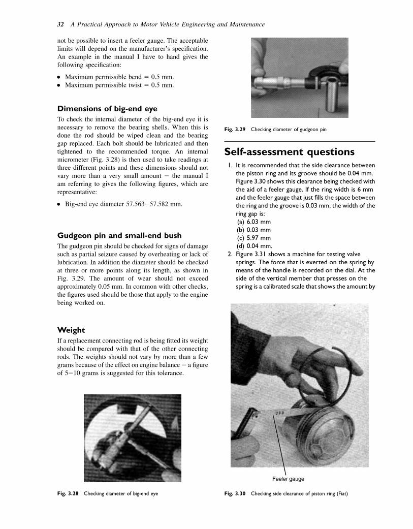
not be possible to insert a feeler gauge. The acceptablelimits will depend on the manufacturer’s specification.An example in the manual I have to hand gives thefollowing specification:
� Maximum permissible bend 5 0.5 mm.� Maximum permissible twist 5 0.5 mm.
Dimensions of big-end eye
To check the internal diameter of the big-end eye it isnecessary to remove the bearing shells. When this isdone the rod should be wiped clean and the bearinggap replaced. Each bolt should be lubricated and thentightened to the recommended torque. An internalmicrometer (Fig. 3.28) is then used to take readings atthree different points and these dimensions should notvary more than a very small amount e the manual Iam referring to gives the following figures, which arerepresentative:
� Big-end eye diameter 57.563e57.582 mm.
Gudgeon pin and small-end bush
The gudgeon pin should be checked for signs of damagesuch as partial seizure caused by overheating or lack oflubrication. In addition the diameter should be checkedat three or more points along its length, as shown inFig. 3.29. The amount of wear should not exceedapproximately 0.05 mm. In common with other checks,the figures used should be those that apply to the enginebeing worked on.
Weight
If a replacement connecting rod is being fitted its weightshould be compared with that of the other connectingrods. The weights should not vary by more than a fewgrams because of the effect on engine balancee a figureof 5e10 grams is suggested for this tolerance.
Self-assessment questions1. It is recommended that the side clearance between
the piston ring and its groove should be 0.04 mm.Figure 3.30 shows this clearance being checked withthe aid of a feeler gauge. If the ring width is 6 mmand the feeler gauge that just fills the space betweenthe ring and the groove is 0.03 mm, the width of thering gap is:(a) 6.03 mm(b) 0.03 mm(c) 5.97 mm(d) 0.04 mm.
2. Figure 3.31 shows a machine for testing valvesprings. The force that is exerted on the spring bymeans of the handle is recorded on the dial. At theside of the vertical member that presses on thespring is a calibrated scale that shows the amount by
Fig. 3.28 Checking diameter of big-end eye
Fig. 3.29 Checking diameter of gudgeon pin
Fig. 3.30 Checking side clearance of piston ring (Fiat)
32 A Practical Approach to Motor Vehicle Engineering and Maintenance
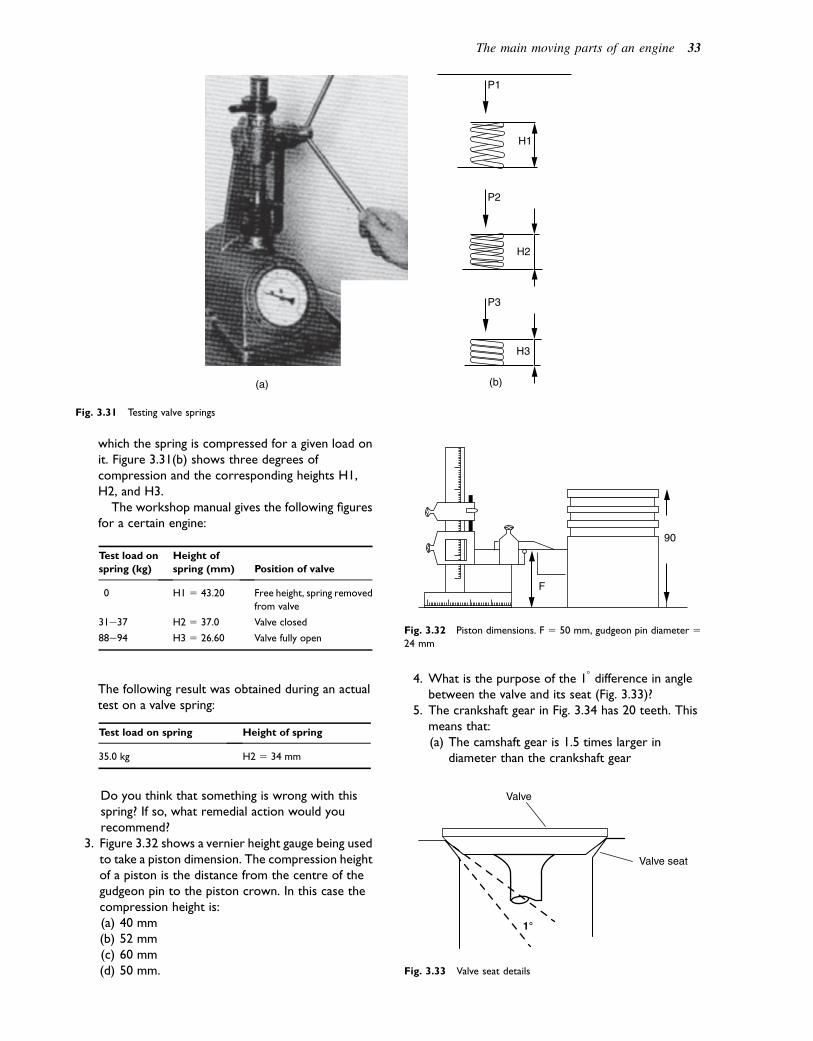
which the spring is compressed for a given load onit. Figure 3.31(b) shows three degrees ofcompression and the corresponding heights H1,H2, and H3.
The workshop manual gives the following figuresfor a certain engine:
Test load on
spring (kg)
Height of
spring (mm) Position of valve
0 H1 5 43.20 Free height, spring removed
from valve
31e37 H2 5 37.0 Valve closed
88e94 H3 5 26.60 Valve fully open
The following result was obtained during an actualtest on a valve spring:
Test load on spring Height of spring
35.0 kg H2 5 34 mm
Do you think that something is wrong with thisspring? If so, what remedial action would yourecommend?
3. Figure 3.32 shows a vernier height gauge being usedto take a piston dimension. The compression heightof a piston is the distance from the centre of thegudgeon pin to the piston crown. In this case thecompression height is:(a) 40 mm(b) 52 mm(c) 60 mm(d) 50 mm.
4. What is the purpose of the 18 difference in anglebetween the valve and its seat (Fig. 3.33)?
5. The crankshaft gear in Fig. 3.34 has 20 teeth. Thismeans that:(a) The camshaft gear is 1.5 times larger in
diameter than the crankshaft gear
(a) (b)
P3
P2
P1
H3
H2
H1
Fig. 3.31 Testing valve springs
90
F
Fig. 3.32 Piston dimensions. F 5 50 mm, gudgeon pin diameter 524 mm
Valve
Valve seat
1°
Fig. 3.33 Valve seat details
The main moving parts of an engine 33
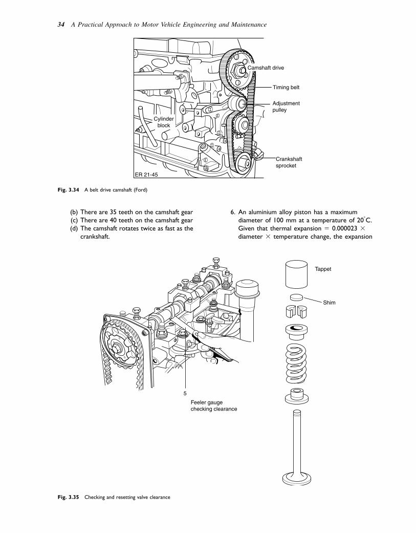
(b) There are 35 teeth on the camshaft gear(c) There are 40 teeth on the camshaft gear(d) The camshaft rotates twice as fast as the
crankshaft.
6. An aluminium alloy piston has a maximumdiameter of 100 mm at a temperature of 208C.Given that thermal expansion 5 0.000023 3diameter 3 temperature change, the expansion
ER 21-45
Timing belt
Adjustmentpulley
Crankshaftsprocket
Cylinderblock
Camshaft drive
Fig. 3.34 A belt drive camshaft (Ford)
Tappet
Shim
5
Feeler gaugechecking clearance
Fig. 3.35 Checking and resetting valve clearance
34 A Practical Approach to Motor Vehicle Engineering and Maintenance
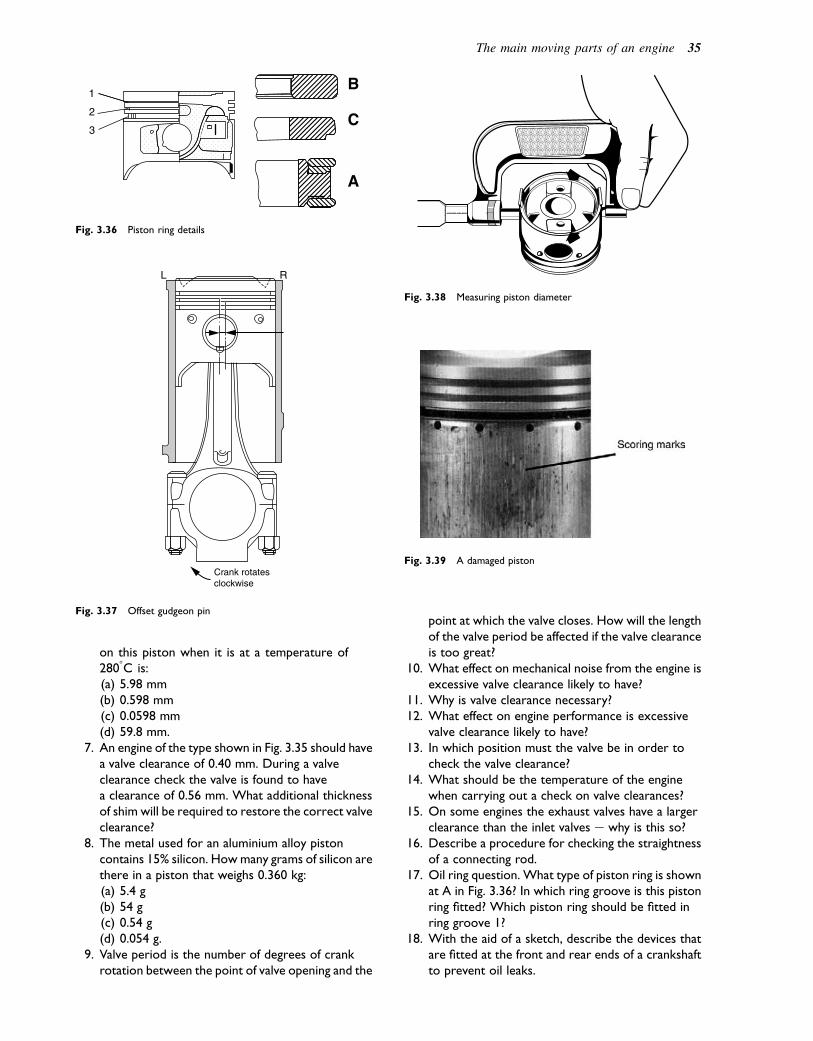
on this piston when it is at a temperature of2808C is:(a) 5.98 mm(b) 0.598 mm(c) 0.0598 mm(d) 59.8 mm.
7. An engine of the type shown in Fig. 3.35 should havea valve clearance of 0.40 mm. During a valveclearance check the valve is found to havea clearance of 0.56 mm. What additional thicknessof shim will be required to restore the correct valveclearance?
8. The metal used for an aluminium alloy pistoncontains 15% silicon. Howmany grams of silicon arethere in a piston that weighs 0.360 kg:(a) 5.4 g(b) 54 g(c) 0.54 g(d) 0.054 g.
9. Valve period is the number of degrees of crankrotation between the point of valve opening and the
point at which the valve closes. How will the lengthof the valve period be affected if the valve clearanceis too great?
10. What effect on mechanical noise from the engine isexcessive valve clearance likely to have?
11. Why is valve clearance necessary?12. What effect on engine performance is excessive
valve clearance likely to have?13. In which position must the valve be in order to
check the valve clearance?14. What should be the temperature of the engine
when carrying out a check on valve clearances?15. On some engines the exhaust valves have a larger
clearance than the inlet valves e why is this so?16. Describe a procedure for checking the straightness
of a connecting rod.17. Oil ring question. What type of piston ring is shown
at A in Fig. 3.36? In which ring groove is this pistonring fitted? Which piston ring should be fitted inring groove 1?
18. With the aid of a sketch, describe the devices thatare fitted at the front and rear ends of a crankshaftto prevent oil leaks.
1
2
3
B
C
A
Fig. 3.36 Piston ring details
Crank rotatesclockwise
L R
Fig. 3.37 Offset gudgeon pin
Fig. 3.38 Measuring piston diameter
Fig. 3.39 A damaged piston
The main moving parts of an engine 35
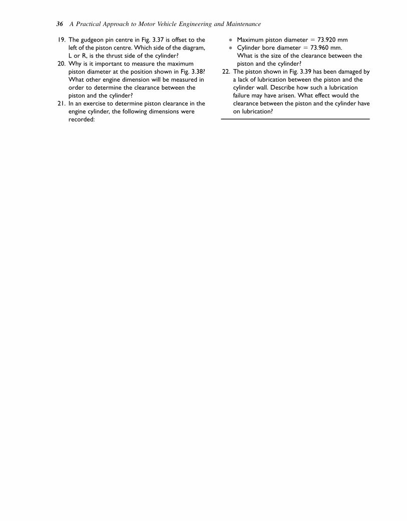
19. The gudgeon pin centre in Fig. 3.37 is offset to theleft of the piston centre. Which side of the diagram,L or R, is the thrust side of the cylinder?
20. Why is it important to measure the maximumpiston diameter at the position shown in Fig. 3.38?What other engine dimension will be measured inorder to determine the clearance between thepiston and the cylinder?
21. In an exercise to determine piston clearance in theengine cylinder, the following dimensions wererecorded:
� Maximum piston diameter 5 73.920 mm� Cylinder bore diameter 5 73.960 mm.
What is the size of the clearance between thepiston and the cylinder?
22. The piston shown in Fig. 3.39 has been damaged bya lack of lubrication between the piston and thecylinder wall. Describe how such a lubricationfailure may have arisen. What effect would theclearance between the piston and the cylinder haveon lubrication?
36 A Practical Approach to Motor Vehicle Engineering and Maintenance

4Multi-cylinder engines
Topics covered in thischapter
Condition checks on cylinder headValve guidesChecking valve stem clearance in the valve guideValve oil sealsDamaged cylinder head gasketCracks and other flawsFactors that influence combustion chamber designPre-ignitionDetonationNeed for high compression ratioScavengingTypes of combustion chambersDetails of cylinder block and crankcaseCylinder linersCylinder block condition checksCylinder bore wear
During the 120 or so years that motor vehicles have beenin use the four-stroke reciprocating engine has becomeestablished as the main means of propulsion. Earlymotor cars often used a single-cylinder engine thatwas not very powerful. As motor vehicles developed,the need for more engine power became apparent. Asingle-cylinder engine can be made more powerful byincreasing its size, but it still leaves a problem: thereis only one power stroke for every two revolutions ofthe crankshaft e this uneven application of power tothe transmission of the vehicle is not very satisfactory.A solution to this problem is to have an engine witha number of cylinders. Because each cylinder has apower stroke every two revolutions of the crankshaft,a four-cylinder enginewill produce four power strokes intwo revolutions of the crankshaft. This provides a muchsmoother supply of power. The period between powerstrokes is often expressed in degrees of crankshaftrotation as: angle between power strokes 5 720/N,where 720 is the number of degrees in two revolutionsof the crankshaft and N is the number of cylinders thatthe engine has.
A four-cylinder engine has 1808 of crankshaft rotationbetween power strokes, a six-cylinder one has 1208, andan eight-cylinder one has 908. In general, the more cylin-ders there are in an engine, the smoother will be itsapplication of power to the transmission system.Figure 4.1 shows the three basic engine layouts thatare commonly used.
Cylinder arrangements
In-line engine
In this type of engine the cylinders are arranged alongthe length of the engine. Four or six cylinders are thetypes most often used. Eight-cylinder engines havebeen used but their greater length requires a very longbonnet and restricts the amount of space that is availablefor use in carrying passengers or goods.
The ‘V’ engine
In these engines the cylinders are arranged on each sideof the crankshaft as shown in Fig. 4.1 and this results ina shorter engine length. The banks of cylinders areplaced at an angle which, in some engines, is 908.
The horizontally opposed engine
In this engine the cylinders are horizontal and placed oneach side of the crankshaft. This produces an engine thatsits low down in the vehicle structure and this makes itsuitable for use in rear-engine vehicles.
Engine structure e the mainfixed parts
Figure 4.2 shows the layout of the most evident struc-tural features of a four-cylinder in-line engine. Thecomponents listed are to be found in all engines,although their form may vary considerably.
� 2011 Allan Bonnick and Derek Newbold. Published by Elsevier Ltd. All rights reserved
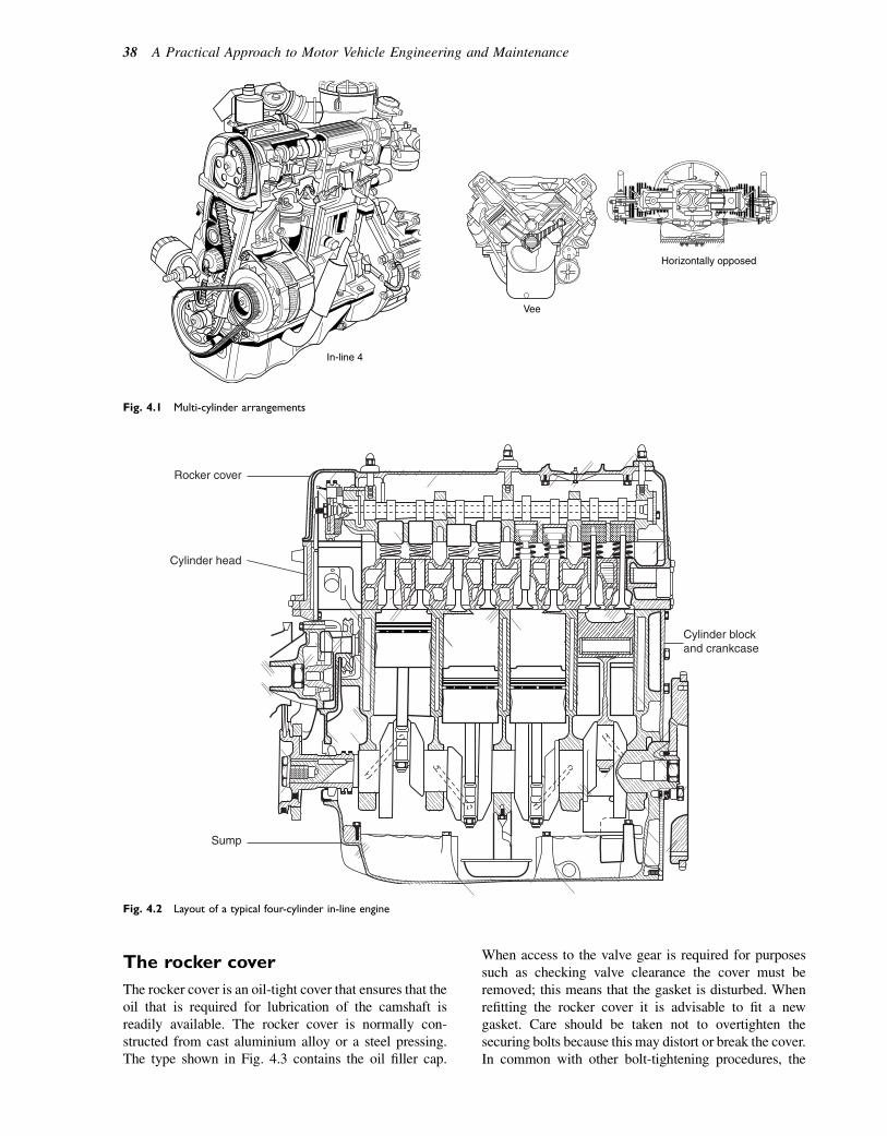
The rocker cover
The rocker cover is an oil-tight cover that ensures that theoil that is required for lubrication of the camshaft isreadily available. The rocker cover is normally con-structed from cast aluminium alloy or a steel pressing.The type shown in Fig. 4.3 contains the oil filler cap.
When access to the valve gear is required for purposessuch as checking valve clearance the cover must beremoved; this means that the gasket is disturbed. Whenrefitting the rocker cover it is advisable to fit a newgasket. Care should be taken not to overtighten thesecuring bolts because this may distort or break the cover.In common with other bolt-tightening procedures, the
Vee
In-line 4
Horizontally opposed
Fig. 4.1 Multi-cylinder arrangements
Sump
Cylinder head
Rocker cover
Cylinder blockand crankcase
Fig. 4.2 Layout of a typical four-cylinder in-line engine
38 A Practical Approach to Motor Vehicle Engineering and Maintenance
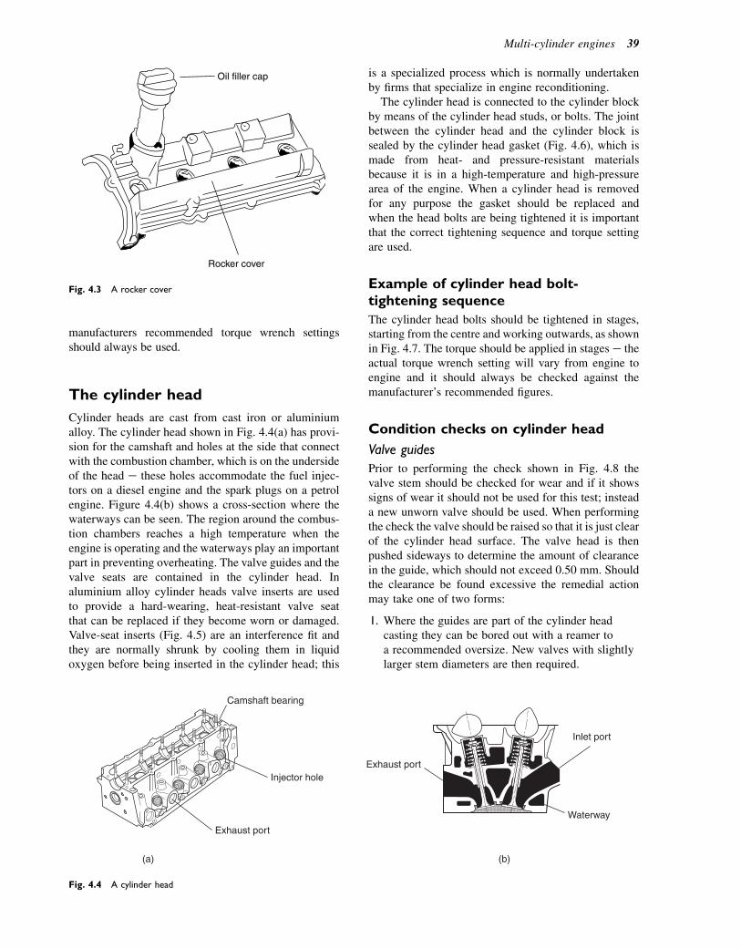
manufacturers recommended torque wrench settingsshould always be used.
The cylinder head
Cylinder heads are cast from cast iron or aluminiumalloy. The cylinder head shown in Fig. 4.4(a) has provi-sion for the camshaft and holes at the side that connectwith the combustion chamber, which is on the undersideof the head e these holes accommodate the fuel injec-tors on a diesel engine and the spark plugs on a petrolengine. Figure 4.4(b) shows a cross-section where thewaterways can be seen. The region around the combus-tion chambers reaches a high temperature when theengine is operating and the waterways play an importantpart in preventing overheating. The valve guides and thevalve seats are contained in the cylinder head. Inaluminium alloy cylinder heads valve inserts are usedto provide a hard-wearing, heat-resistant valve seatthat can be replaced if they become worn or damaged.Valve-seat inserts (Fig. 4.5) are an interference fit andthey are normally shrunk by cooling them in liquidoxygen before being inserted in the cylinder head; this
is a specialized process which is normally undertakenby firms that specialize in engine reconditioning.
The cylinder head is connected to the cylinder blockby means of the cylinder head studs, or bolts. The jointbetween the cylinder head and the cylinder block issealed by the cylinder head gasket (Fig. 4.6), which ismade from heat- and pressure-resistant materialsbecause it is in a high-temperature and high-pressurearea of the engine. When a cylinder head is removedfor any purpose the gasket should be replaced andwhen the head bolts are being tightened it is importantthat the correct tightening sequence and torque settingare used.
Example of cylinder head bolt-tightening sequence
The cylinder head bolts should be tightened in stages,starting from the centre and working outwards, as shownin Fig. 4.7. The torque should be applied in stages e theactual torque wrench setting will vary from engine toengine and it should always be checked against themanufacturer’s recommended figures.
Condition checks on cylinder head
Valve guides
Prior to performing the check shown in Fig. 4.8 thevalve stem should be checked for wear and if it showssigns of wear it should not be used for this test; insteada new unworn valve should be used. When performingthe check the valve should be raised so that it is just clearof the cylinder head surface. The valve head is thenpushed sideways to determine the amount of clearancein the guide, which should not exceed 0.50 mm. Shouldthe clearance be found excessive the remedial actionmay take one of two forms:
1. Where the guides are part of the cylinder headcasting they can be bored out with a reamer toa recommended oversize. New valves with slightlylarger stem diameters are then required.
Rocker cover
Oil filler cap
Fig. 4.3 A rocker cover
Exhaust port
(a) (b)
Exhaust port
Waterway
Inlet port
Injector hole
Camshaft bearing
Fig. 4.4 A cylinder head
Multi-cylinder engines 39

2. Where the guides are an interference fit in thecylinder head they may be pressed out and replacedby new ones.
Valve oil seals
Valve stem oil seals of the type shown in Fig. 4.9 play animportant part in preventing oil from entering thecombustion chamber. If they are defective they canaffect engine emissions and oil consumption.
Cylinder head gasket
In the event of cylinder head gasket failure the gasketitself would be examined because this should help toreveal the cause of failure. There are several probablecauses of such failure, but the one shown in Fig. 4.10is believed to have been caused by material trappedunder the gasket when it was first fitted e some other
gasket failures are discussed in the chapter on enginefaults (Chapter 17).
In this example of gasket failure, combustion gas hasentered the engine cooling system and coolant hasentered the combustion chamber, both events causingserious problems that are covered in detail in the chapteron engine cooling systems (Chapter 13).
Cracks and other flaws
Cracks between valve seats and between a valve seat anda waterway sometimes arise when an engine has suffereda cooling system failure. This type of crack is shown inFig. 4.11. Special penetrating dyes have been developedto search for cracks.When the affected part is thoroughlyclean the dye is painted on and allowed to dry. Aftera short period the dye is wiped off and the crack willshow up clearly because the dye has entered into it.Various proprietary brands of this treatment are avail-able. Other methods of crack detection rely on principlesof magnetism. In this procedure the object being tested ismagnetized in special apparatus e iron filings are thenapplied to the affected surface and cracks will show upas the filings line up along the crack.
Valve seats
Valve seats should be examined to ensure that the valvesare seating correctly. If a valve seat is worn it may be re-cut with a special tool of the type shown in Fig. 4.12.
In cases of extreme wear the valve seat may needrenewing by fitting a valve-seat insert. The inserts arean interference fit in the cylinder head as shown inFig. 4.13. In some cases the inserts are pressed in andin other cases they are cooled in liquid nitrogen to shrinkthem prior to fitting to the cylinder head.
Combustion chambers
The combustion chamber is the space formed by thechamber in the cylinder head and the piston crown. Itcontains the valve heads and valve seats, and the sparkingplug. These features are accommodated in a relativelysmall space, which is determined by the cylinder borediameter and the compression ratio.
Valve seat insert
Fig. 4.5 Valve-seat insert
A
ER21-100
Cylinder head gasket
A - locating dowelsCylinder block
Fig. 4.6 Cylinder head gasket and dowels that locate it
40 A Practical Approach to Motor Vehicle Engineering and Maintenance
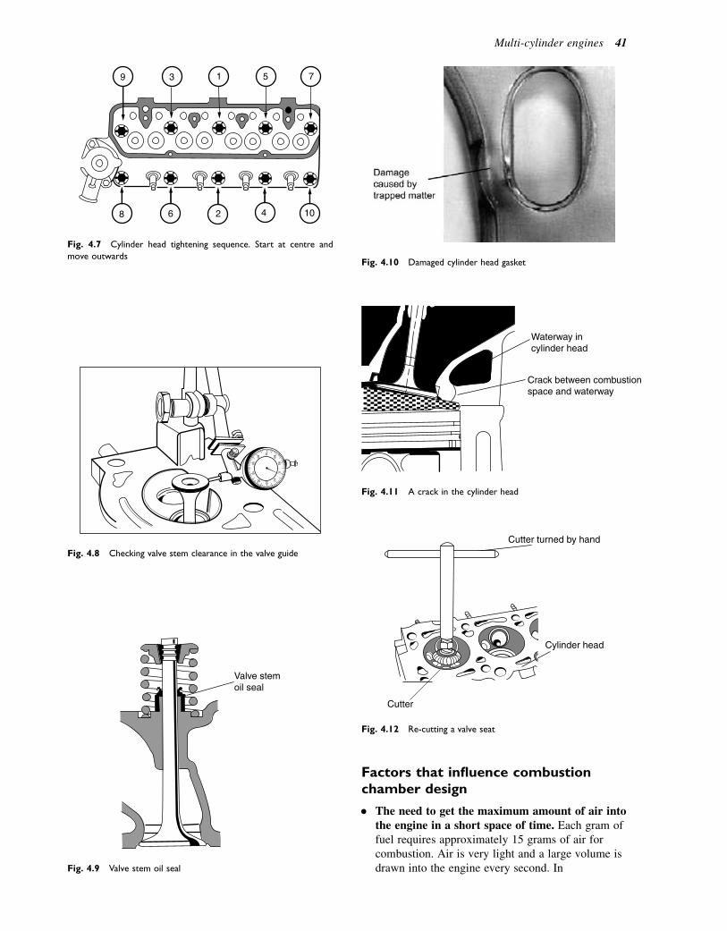
Factors that influence combustionchamber design
� The need to get the maximum amount of air intothe engine in a short space of time. Each gram offuel requires approximately 15 grams of air forcombustion. Air is very light and a large volume isdrawn into the engine every second. In
8 6 2 4 10
9 3 1 5 7
Fig. 4.7 Cylinder head tightening sequence. Start at centre and
move outwards
Fig. 4.8 Checking valve stem clearance in the valve guide
Valve stemoil seal
Fig. 4.9 Valve stem oil seal
Fig. 4.10 Damaged cylinder head gasket
Waterway incylinder head
Crack between combustionspace and waterway
Fig. 4.11 A crack in the cylinder head
Cylinder head
Cutter
Cutter turned by hand
Fig. 4.12 Re-cutting a valve seat
Multi-cylinder engines 41
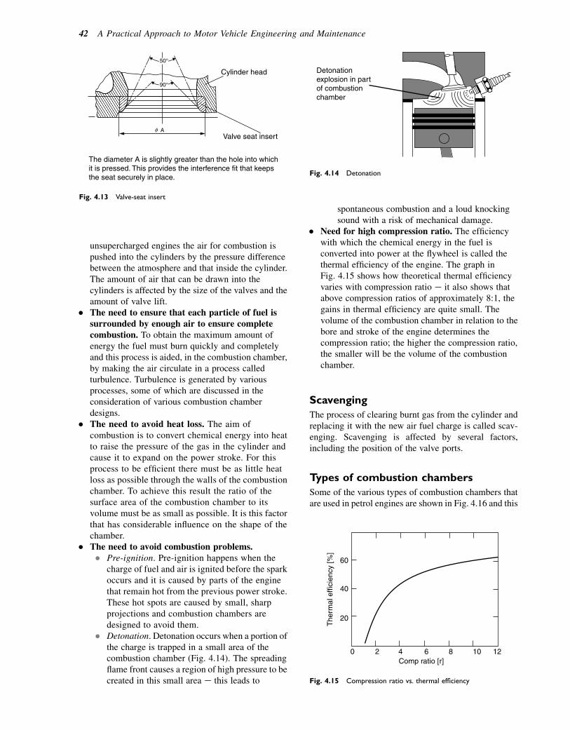
unsupercharged engines the air for combustion ispushed into the cylinders by the pressure differencebetween the atmosphere and that inside the cylinder.The amount of air that can be drawn into thecylinders is affected by the size of the valves and theamount of valve lift.
� The need to ensure that each particle of fuel issurrounded by enough air to ensure completecombustion. To obtain the maximum amount ofenergy the fuel must burn quickly and completelyand this process is aided, in the combustion chamber,by making the air circulate in a process calledturbulence. Turbulence is generated by variousprocesses, some of which are discussed in theconsideration of various combustion chamberdesigns.
� The need to avoid heat loss. The aim ofcombustion is to convert chemical energy into heatto raise the pressure of the gas in the cylinder andcause it to expand on the power stroke. For thisprocess to be efficient there must be as little heatloss as possible through the walls of the combustionchamber. To achieve this result the ratio of thesurface area of the combustion chamber to itsvolume must be as small as possible. It is this factorthat has considerable influence on the shape of thechamber.
� The need to avoid combustion problems.� Pre-ignition. Pre-ignition happens when the
charge of fuel and air is ignited before the sparkoccurs and it is caused by parts of the enginethat remain hot from the previous power stroke.These hot spots are caused by small, sharpprojections and combustion chambers aredesigned to avoid them.
� Detonation. Detonation occurs when a portion ofthe charge is trapped in a small area of thecombustion chamber (Fig. 4.14). The spreadingflame front causes a region of high pressure to becreated in this small area e this leads to
spontaneous combustion and a loud knockingsound with a risk of mechanical damage.
� Need for high compression ratio. The efficiencywith which the chemical energy in the fuel isconverted into power at the flywheel is called thethermal efficiency of the engine. The graph inFig. 4.15 shows how theoretical thermal efficiencyvaries with compression ratio e it also shows thatabove compression ratios of approximately 8:1, thegains in thermal efficiency are quite small. Thevolume of the combustion chamber in relation to thebore and stroke of the engine determines thecompression ratio; the higher the compression ratio,the smaller will be the volume of the combustionchamber.
Scavenging
The process of clearing burnt gas from the cylinder andreplacing it with the new air fuel charge is called scav-enging. Scavenging is affected by several factors,including the position of the valve ports.
Types of combustion chambers
Some of the various types of combustion chambers thatare used in petrol engines are shown in Fig. 4.16 and this
Detonationexplosion in partof combustionchamber
Fig. 4.14 Detonation
60
40
20
0 2 4Comp ratio [r]
The
rmal
effi
cien
cy [%
]
6 8 10 12
Fig. 4.15 Compression ratio vs. thermal efficiency
50°
90°
A
The diameter A is slightly greater than the hole into whichit is pressed. This provides the interference fit that keepsthe seat securely in place.
Valve seat insert
Cylinder head
Fig. 4.13 Valve-seat insert
42 A Practical Approach to Motor Vehicle Engineering and Maintenance
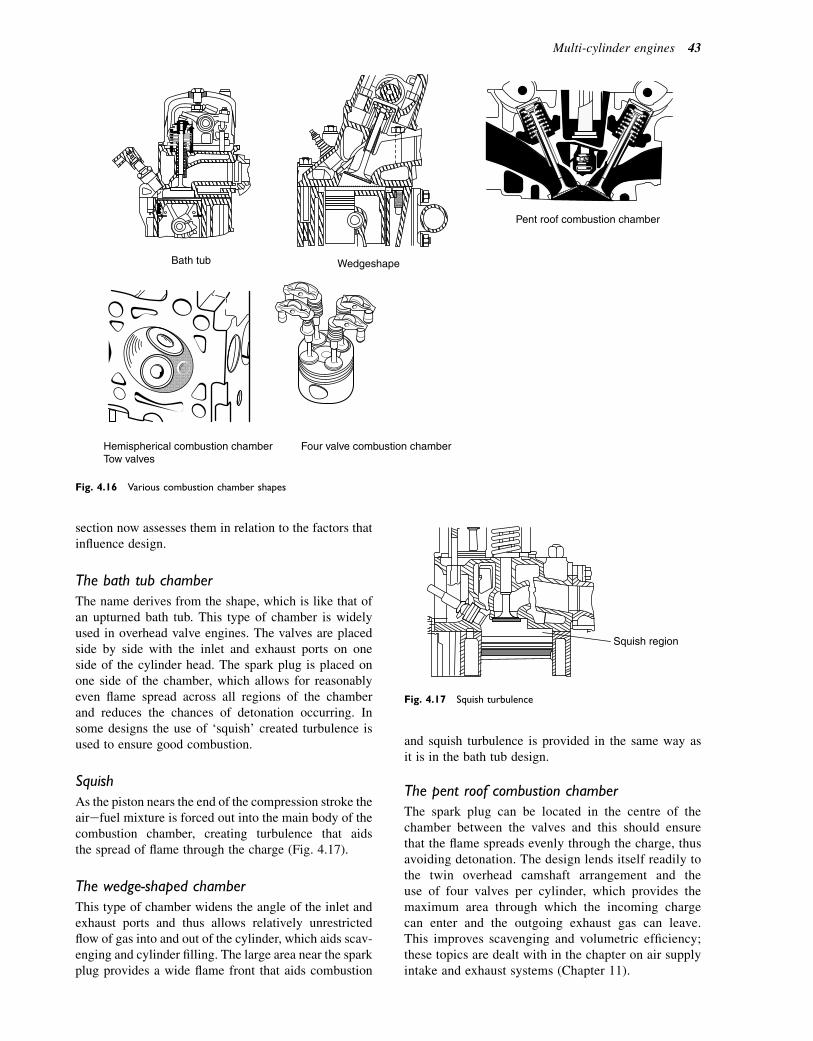
section now assesses them in relation to the factors thatinfluence design.
The bath tub chamber
The name derives from the shape, which is like that ofan upturned bath tub. This type of chamber is widelyused in overhead valve engines. The valves are placedside by side with the inlet and exhaust ports on oneside of the cylinder head. The spark plug is placed onone side of the chamber, which allows for reasonablyeven flame spread across all regions of the chamberand reduces the chances of detonation occurring. Insome designs the use of ‘squish’ created turbulence isused to ensure good combustion.
Squish
As the piston nears the end of the compression stroke theairefuel mixture is forced out into the main body of thecombustion chamber, creating turbulence that aidsthe spread of flame through the charge (Fig. 4.17).
The wedge-shaped chamber
This type of chamber widens the angle of the inlet andexhaust ports and thus allows relatively unrestrictedflow of gas into and out of the cylinder, which aids scav-enging and cylinder filling. The large area near the sparkplug provides a wide flame front that aids combustion
and squish turbulence is provided in the same way asit is in the bath tub design.
The pent roof combustion chamber
The spark plug can be located in the centre of thechamber between the valves and this should ensurethat the flame spreads evenly through the charge, thusavoiding detonation. The design lends itself readily tothe twin overhead camshaft arrangement and theuse of four valves per cylinder, which provides themaximum area through which the incoming chargecan enter and the outgoing exhaust gas can leave.This improves scavenging and volumetric efficiency;these topics are dealt with in the chapter on air supplyintake and exhaust systems (Chapter 11).
Bath tub Wedgeshape
Pent roof combustion chamber
Hemispherical combustion chamberTow valves
Four valve combustion chamber
Fig. 4.16 Various combustion chamber shapes
Squish region
Fig. 4.17 Squish turbulence
Multi-cylinder engines 43
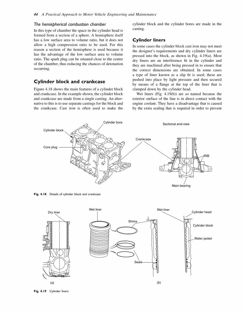
The hemispherical combustion chamber
In this type of chamber the space in the cylinder head isformed from a section of a sphere. A hemisphere itselfhas a low surface area to volume ratio, but it does notallow a high compression ratio to be used. For thisreason a section of the hemisphere is used because ithas the advantage of the low surface area to volumeratio. The spark plug can be situated close to the centreof the chamber, thus reducing the chances of detonationoccurring.
Cylinder block and crankcase
Figure 4.18 shows the main features of a cylinder blockand crankcase. In the example shown, the cylinder blockand crankcase are made from a single casting. An alter-native to this is to use separate castings for the block andthe crankcase. Cast iron is often used to make the
cylinder block and the cylinder bores are made in thecasting.
Cylinder liners
In some cases the cylinder block cast iron may not meetthe designer’s requirements and dry cylinder liners arepressed into the block, as shown in Fig. 4.19(a). Mostdry liners are an interference fit in the cylinder andthey are machined after being pressed in to ensure thatthe correct dimensions are obtained. In some casesa type of liner known as a slip fit is used; these arepushed into place by light pressure and then securedby means of a flange at the top of the liner that isclamped down by the cylinder head.
Wet liners (Fig. 4.19(b)) are so named because theexterior surface of the line is in direct contact with theengine coolant. They have a disadvantage that is causedby the extra sealing that is required in order to prevent
Crankcase
Cylinder bore
Cylinder block
Core plug
Sectional end-view
RIB
Main bearing
Fig. 4.18 Details of cylinder block and crankcase
Dry linerWet liner
Shims
Wet linerCylinder head
Cylinder block
Water jacket
Seals
(a) (b)
Fig. 4.19 Cylinder liners
44 A Practical Approach to Motor Vehicle Engineering and Maintenance
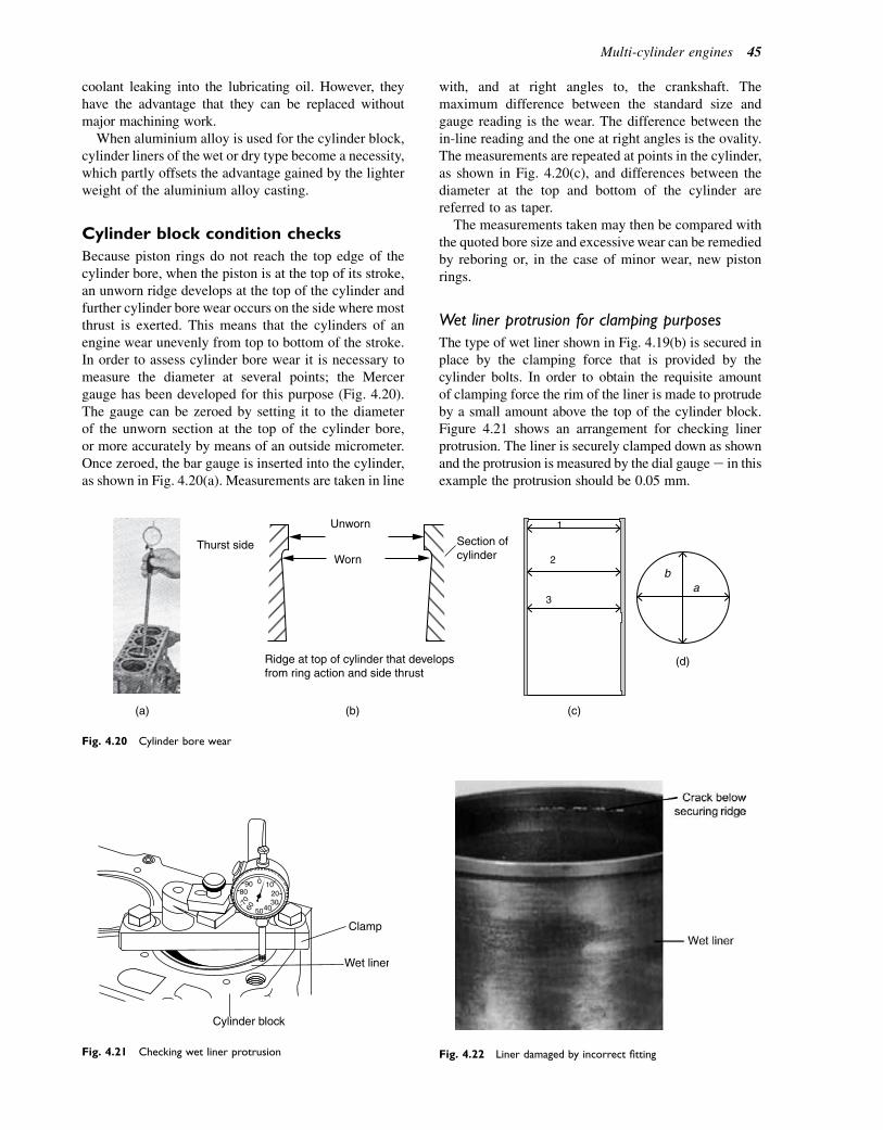
coolant leaking into the lubricating oil. However, theyhave the advantage that they can be replaced withoutmajor machining work.
When aluminium alloy is used for the cylinder block,cylinder liners of the wet or dry type become a necessity,which partly offsets the advantage gained by the lighterweight of the aluminium alloy casting.
Cylinder block condition checks
Because piston rings do not reach the top edge of thecylinder bore, when the piston is at the top of its stroke,an unworn ridge develops at the top of the cylinder andfurther cylinder bore wear occurs on the side where mostthrust is exerted. This means that the cylinders of anengine wear unevenly from top to bottom of the stroke.In order to assess cylinder bore wear it is necessary tomeasure the diameter at several points; the Mercergauge has been developed for this purpose (Fig. 4.20).The gauge can be zeroed by setting it to the diameterof the unworn section at the top of the cylinder bore,or more accurately by means of an outside micrometer.Once zeroed, the bar gauge is inserted into the cylinder,as shown in Fig. 4.20(a). Measurements are taken in line
with, and at right angles to, the crankshaft. Themaximum difference between the standard size andgauge reading is the wear. The difference between thein-line reading and the one at right angles is the ovality.The measurements are repeated at points in the cylinder,as shown in Fig. 4.20(c), and differences between thediameter at the top and bottom of the cylinder arereferred to as taper.
The measurements taken may then be compared withthe quoted bore size and excessive wear can be remediedby reboring or, in the case of minor wear, new pistonrings.
Wet liner protrusion for clamping purposes
The type of wet liner shown in Fig. 4.19(b) is secured inplace by the clamping force that is provided by thecylinder bolts. In order to obtain the requisite amountof clamping force the rim of the liner is made to protrudeby a small amount above the top of the cylinder block.Figure 4.21 shows an arrangement for checking linerprotrusion. The liner is securely clamped down as shownand the protrusion is measured by the dial gaugee in thisexample the protrusion should be 0.05 mm.
1
2
3
ba
(d)
(c)(b)(a)
Thurst side
Unworn
Worn
Ridge at top of cylinder that developsfrom ring action and side thrust
Section ofcylinder
Fig. 4.20 Cylinder bore wear
90 0 10
Clamp
Wet liner
Cylinder block
80 20
6070 30
4050
Fig. 4.21 Checking wet liner protrusion Fig. 4.22 Liner damaged by incorrect fitting
Multi-cylinder engines 45
Figure 4.22 shows the type of failure that may occur ifthe liner is not fitted correctly. The effect of sucha failure upon engine performance is likely to be severeand may include:
� Loss of power� Coolant in the oil� Combustion gas in the cooling system� Coolant inside the cylinder� Problems with combustion and emissions controls.
The crankcase
The crankcase carries the main bearing supports and insome cases it is made as a separate casting from a lightalloy, which reduces overall engine weight.
Sump
Thesump (Fig.4.23), oroil pan, isnormallymade as a steelpressing and itsmain function is to act as a reservoir for theoil that lubricates the engine. It is separated fromthecrank-case by a gasket and this, in common with other gaskets,must be positioned accurately prior to reassembling thesump to the crankcase. When correctly positioned, theset screws that hold it in placemust be tightened gradually,in sequence, and finally to the correct torque.
Self-assessment questions1. Figure 4.20 shows the positions in an engine
cylinder at which measurements of diameter aretaken in order to assess wear. The measurementsare taken in line and at right angles to thecrankshaft, at three levels as shown. The thirdmeasurement is taken at the lowest extent ofpiston ring travel. The terms ovality and taper areused to describe the condition of the cylinder bore.Ovality is the difference betweeen a and b, andtaper is the difference between the largest diameterat the first measurement and the smallest diameter
at the third measurement. In an example, thefollowing dimensions were recorded:� First measurement, a5 74.22 mm, b5 73.95 mm� Second measurement, a 5 74.19 mm, b 5
74.00 mm� Third measurement, a 5 74.00 mm, b 5
73.97 mm.The maximum ovality is:(a) 0.22 mm(b) 0.19 mm(c) 0.27 mm(d) 0.03 mm.
2. The taper is:(a) 0.25 mm(b) 0.03 mm(c) 0.19 mm(d) 0.27 mm.
3. Describe the repairs that can be undertaken ifexcessive oil consumption is caused by worn valveguides.
4. How many degrees of crank rotation are therebetween firing strokes on a four-cylinder, four-stroke, in-line engine?
5. What steps are necessary when refitting analuminium alloy cylinder head?
6. Why are wet cylinder liners normally fitted toaluminium alloy cylinder blocks? How are wet linerssecured in a cylinder block?
7. Describe the features of engine design that produce‘squish’ turbulence.
8. What is the reason for producing turbulence ina combustion chamber?
9. What is the probable effect of a ‘blown’ cylinderhead gasket on an engine cooling system?
10. Describe the procedure for checking piston ringgap. How can the ring gap be increased if it is toosmall?
11. How does compression ratio affect the thermalefficiency of an engine?
12. Describe how a cylinder head can be examined forprobable cracks?
13. With the aid of a sketch, describe the types ofvalve seats that are used in aluminium alloycylinder heads.
14. What is the difference between pre-ignition anddetonation?
15. Describe some of the possible causes of pre-ignition? What are the symptoms of pre-ignition?
16. Why is an eight-cylinder engine generally smootherrunning than a four-cylinder one?
17. When cylinders and pistons are worn, combustiongas enters the crankcase. What happens to this gasand how can it affect the lubricating oil in the sump?
18. How can a badly pitted valve seat be repaired?
Sump
Fig. 4.23 The sump
46 A Practical Approach to Motor Vehicle Engineering and Maintenance
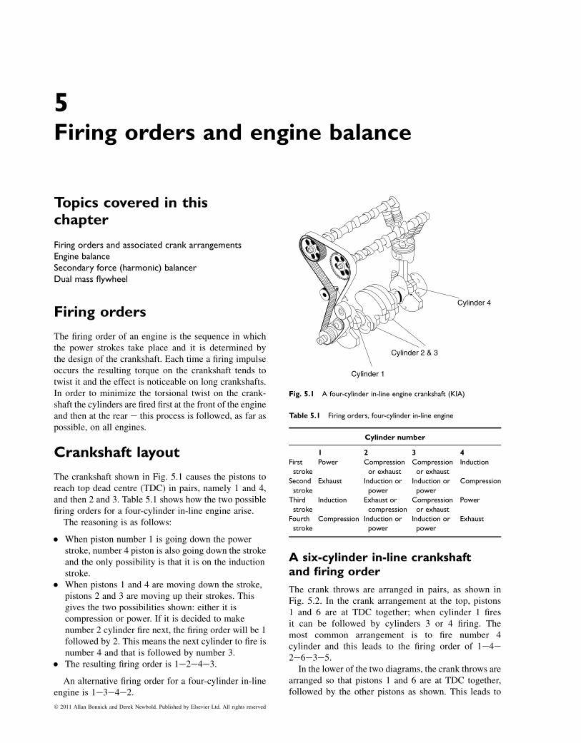
5Firing orders and engine balance
Topics covered in thischapter
Firing orders and associated crank arrangementsEngine balanceSecondary force (harmonic) balancerDual mass flywheel
Firing orders
The firing order of an engine is the sequence in whichthe power strokes take place and it is determined bythe design of the crankshaft. Each time a firing impulseoccurs the resulting torque on the crankshaft tends totwist it and the effect is noticeable on long crankshafts.In order to minimize the torsional twist on the crank-shaft the cylinders are fired first at the front of the engineand then at the rear e this process is followed, as far aspossible, on all engines.
Crankshaft layout
The crankshaft shown in Fig. 5.1 causes the pistons toreach top dead centre (TDC) in pairs, namely 1 and 4,and then 2 and 3. Table 5.1 shows how the two possiblefiring orders for a four-cylinder in-line engine arise.
The reasoning is as follows:
� When piston number 1 is going down the powerstroke, number 4 piston is also going down the strokeand the only possibility is that it is on the inductionstroke.
� When pistons 1 and 4 are moving down the stroke,pistons 2 and 3 are moving up their strokes. Thisgives the two possibilities shown: either it iscompression or power. If it is decided to makenumber 2 cylinder fire next, the firing order will be 1followed by 2. This means the next cylinder to fire isnumber 4 and that is followed by number 3.
� The resulting firing order is 1e2e4e3.
An alternative firing order for a four-cylinder in-lineengine is 1e3e4e2.
A six-cylinder in-line crankshaftand firing order
The crank throws are arranged in pairs, as shown inFig. 5.2. In the crank arrangement at the top, pistons1 and 6 are at TDC together; when cylinder 1 firesit can be followed by cylinders 3 or 4 firing. Themost common arrangement is to fire number 4cylinder and this leads to the firing order of 1e4e2e6e3e5.
In the lower of the two diagrams, the crank throws arearranged so that pistons 1 and 6 are at TDC together,followed by the other pistons as shown. This leads to
Cylinder 4
Cylinder 2 & 3
Cylinder 1
Fig. 5.1 A four-cylinder in-line engine crankshaft (KIA)
Table 5.1 Firing orders, four-cylinder in-line engine
Cylinder number
1 2 3 4
First
stroke
Power Compression
or exhaust
Compression
or exhaust
Induction
Second
stroke
Exhaust Induction or
power
Induction or
power
Compression
Third
stroke
Induction Exhaust or
compression
Compression
or exhaust
Power
Fourth
stroke
Compression Induction or
power
Induction or
power
Exhaust
� 2011 Allan Bonnick and Derek Newbold. Published by Elsevier Ltd. All rights reserved

the other firing order commonly used in six-cylinder in-line engines, i.e. 1e5e3e6e2e4.
Firing first in the front half of the crankshaft and thenas far as possible in the back half minimizes the twistingof the crankshaft that is the cause of torsional vibrations.
A V8 crankshaft and firing order
The use of the V8 layout permits the advantages ofmany cylinders to be accommodated in a short space.
The crankshaft has four crankpins, each of which servestwo connecting rods as shown in Fig. 5.3.
Vibrations and engine balance
If an engine is not properly balanced it will developvibrations, which cause noise and discomfort to vehicleoccupants and, in time, cause damage to components.
There are two main areas of the engine wherevibrations are a problem:
Six-cylinder crankshaft
Alternative crankarrangements
1.6
34. 5
2.
1.6
25. 4
3.
Fig. 5.2 A six-cylinder in-line engine (Toyota)
Front Left BankConnecting Rod
Right BankConnecting Rod
Crankshaft
Nos. 5, 6
Pin Position
Position of cranks
Nos. 7, 8BD
Nos. 3, 4TDNos. 1, 2
90˚
0˚ 180˚ 360˚ 540˚ 720˚
Crankshaft Angle
4 crankpins, 5 main journals
Two connecting rods oneach crankpin
Firing order 1 – 8 – 4 – 3 – 6 – 5 – 7 – 2.
Right Bank Left Bank
Arrangement of cylinders
Bank Angle
No.8Cylinder No.7
CylinderNo.5CylinderNo.3CylinderNo.1Cylinder
No.6CylinderNo.4CylinderNo.2Cylinder
Cylinder
No.8No.1
No.4No.3No.6No.5No.7No.2
Fig. 5.3 A V8 engine (Toyota)
48 A Practical Approach to Motor Vehicle Engineering and Maintenance
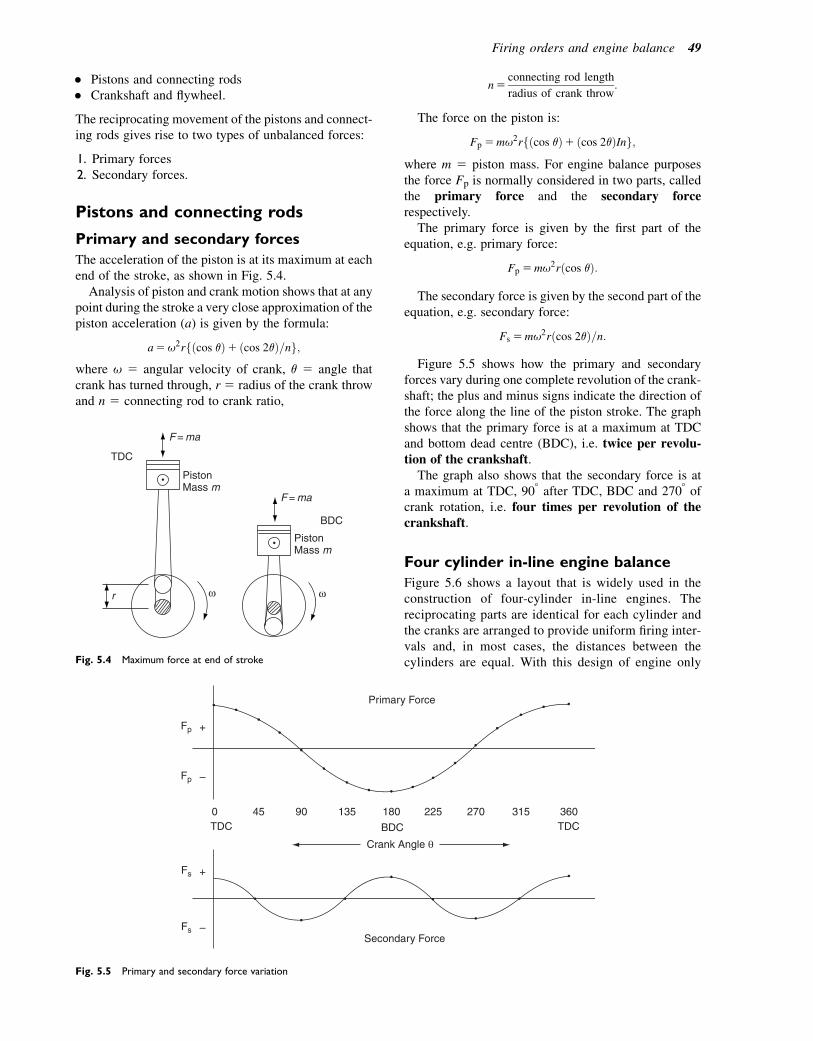
� Pistons and connecting rods� Crankshaft and flywheel.
The reciprocating movement of the pistons and connect-ing rods gives rise to two types of unbalanced forces:
1. Primary forces2. Secondary forces.
Pistons and connecting rods
Primary and secondary forces
The acceleration of the piston is at its maximum at eachend of the stroke, as shown in Fig. 5.4.
Analysis of piston and crank motion shows that at anypoint during the stroke a very close approximation of thepiston acceleration (a) is given by the formula:
a5u2rfðcos qÞ1 ðcos 2qÞ=ng;where u 5 angular velocity of crank, q 5 angle thatcrank has turned through, r 5 radius of the crank throwand n 5 connecting rod to crank ratio,
n5connecting rod length
radius of crank throw:
The force on the piston is:
Fp 5mu2rfðcos qÞ1 ðcos 2qÞIng;where m 5 piston mass. For engine balance purposesthe force Fp is normally considered in two parts, calledthe primary force and the secondary forcerespectively.
The primary force is given by the first part of theequation, e.g. primary force:
Fp 5mu2rðcos qÞ:
The secondary force is given by the second part of theequation, e.g. secondary force:
Fs 5mu2rðcos 2qÞ=n:
Figure 5.5 shows how the primary and secondaryforces vary during one complete revolution of the crank-shaft; the plus and minus signs indicate the direction ofthe force along the line of the piston stroke. The graphshows that the primary force is at a maximum at TDCand bottom dead centre (BDC), i.e. twice per revolu-tion of the crankshaft.
The graph also shows that the secondary force is ata maximum at TDC, 908 after TDC, BDC and 2708 ofcrank rotation, i.e. four times per revolution of thecrankshaft.
Four cylinder in-line engine balance
Figure 5.6 shows a layout that is widely used in theconstruction of four-cylinder in-line engines. Thereciprocating parts are identical for each cylinder andthe cranks are arranged to provide uniform firing inter-vals and, in most cases, the distances between thecylinders are equal. With this design of engine only
r
PistonMass m
PistonMass m
F = ma
F = ma
BDC
TDC
Fig. 5.4 Maximum force at end of stroke
Secondary Force
Primary Force
Crank Angle
Fp
Fp –
Fs –
Fs +
+
TDC BDC TDC 360 315 270 225 180 135 90 45 0
Fig. 5.5 Primary and secondary force variation
Firing orders and engine balance 49
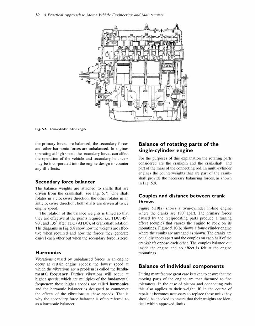
the primary forces are balanced; the secondary forcesand other harmonic forces are unbalanced. In enginesoperating at high speed, the secondary forces can affectthe operation of the vehicle and secondary balancersmay be incorporated into the engine design to counterany ill effects.
Secondary force balancer
The balance weights are attached to shafts that aredriven from the crankshaft (see Fig. 5.7). One shaftrotates in a clockwise direction, the other rotates in ananticlockwise direction; both shafts are driven at twiceengine speed.
The rotation of the balance weights is timed so thatthey are effective at the points required, i.e. TDC, 458,908, and 1358 after TDC (ATDC), of crankshaft rotation.The diagrams in Fig. 5.8 show how the weights are effec-tive when required and how the forces they generatecancel each other out when the secondary force is zero.
Harmonics
Vibrations caused by unbalanced forces in an engineoccur at certain engine speeds; the lowest speed atwhich the vibrations are a problem is called the funda-mental frequency. Further vibrations will occur athigher speeds, which are multiples of the fundamentalfrequency; these higher speeds are called harmonicsand the harmonic balancer is designed to counteractthe effects of the vibrations at these speeds. That iswhy the secondary force balancer is often referred toas a harmonic balancer.
Balance of rotating parts of thesingle-cylinder engine
For the purposes of this explanation the rotating partsconsidered are the crankpin and the crankshaft, andpart of the mass of the connecting rod. In multi-cylinderengines the counterweights that are part of the crank-shaft provide the necessary balancing forces, as shownin Fig. 5.9.
Couples and distance between crankthrows
Figure 5.10(a) shows a twin-cylinder in-line enginewhere the cranks are 1808 apart. The primary forcescaused by the reciprocating parts produce a turningeffect (couple) that causes the engine to rock on itsmountings. Figure 5.10(b) shows a four-cylinder enginewhere the cranks are arranged as shown. The cranks areequal distances apart and the couples on each half of thecrankshaft oppose each other. The couples balance outinside the engine and no effect is felt at the enginemountings.
Balance of individual components
During manufacture great care is taken to ensure that themoving parts of the engine are manufactured to finetolerances. In the case of pistons and connecting rodsthis also applies to their weight. If, in the course ofrepair, it becomes necessary to replace these units theyshould be checked to ensure that their weights are iden-tical within approved limits.
Fig. 5.6 Four-cylinder in-line engine
50 A Practical Approach to Motor Vehicle Engineering and Maintenance

The crankshaft and flywheel are usually balanced asa unit and balance is achieved by drilling holes in appro-priate positions; these can often be seen in the crank webor flywheel. To ensure that the balance is not upsetcrankshafts are fitted with devices such as dowels thatensure that the flywheel is always correctly fitted to it,as shown in Fig. 5.11.
Torsional vibration
The vibrations associated with the crankshaft andflywheel are caused by the interaction between them
TDC 45° ATDC 90° ATDC 135° ATDC
Secondary Force Balancer
Balance Mass
Fig. 5.8 Principle of secondary force balancer
VTEC Camshaft EX
VTEC IN
VTEC EX
VTC Actuator IN
CamshaftChain Drive
HydraulicChain Tensioner
Balance shafts
The balance shafts are driven at twice crankshaftspeed
VTEC Camshaft IN
Fig. 5.7 A Honda VTEC engine with harmonic balancer
Counterweights
Fig. 5.9 Crankshaft counterweights
Firing orders and engine balance 51

and the effect is most evident in engines with a longcrankshaft. When a cylinder at the front end of a crank-shaft fires, the torque exerted on the shaft accelerates theflywheel and in doing so the crankshaft is twistedslightly. The periodic application and removal of crank-shaft torque as each cylinder fires can set up a vibrationcalled torsional vibration. The effect is minimized byfiring cylinders at alternate ends of the engine, but inmany cases the vibrations are a problem because theycan fracture the crankshaft or cause damage in the trans-mission system.
Various types of vibration dampers are fitted toengines to lessen the effect.
Crankshaft damper
The crankshaft torsional vibration damper shown inFig. 5.12 makes use of a layer of rubber between thecentre of the pulley and the mass of the drive-belt rim.The damping effect is provided by the rubber, whichdistorts when vibration attempts to accelerate thedrive-belt pulley mass; the distortion of the rubberconverts vibrational energy into heat, which is thenpassed into the atmosphere and it is this action thatprovides the damping.
The vibration damper in the clutchplate
In a clutch plate of the type shown in Fig. 5.13, the damp-ing effect is provided by the coil springs and the smallfriction surface at the hub of the clutch plate. The springspermit slight movement of the part of the plate that holdsthe linings relative to the hub. This action compresses thesprings and converts energy into heat at the small frictionsurface to provide the damping action.
The dual mass flywheel
Dual mass flywheels are constructed from a number ofseparate parts and they are designed to overcome low-speed torsional vibration that is a problem in some dieselengine vehicles. They are called dual mass flywheelsbecause they have two major mass components. One isthe mass that affects the crankshaft and another mass
CRANKSHAFT
CRANKSHAFT
DOWEL
BOLT
SCREW TEMP
Fig. 5.11 Flywheel fixing to crankshaft
Crankshaft pulley withbuilt-in damper
Damper Rubber
Drive-beltgroove
Crankshaft damper
Fig. 5.12 Crankshaft torsional vibration damper
Couple (a) (b)
Balanced Couples
Fig. 5.10 Couples
52 A Practical Approach to Motor Vehicle Engineering and Maintenance
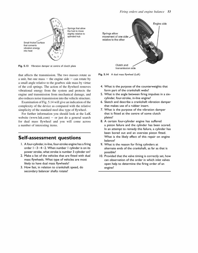
that affects the transmission. The two masses rotate asa unit, but one mass e the engine side e can rotate bya small angle relative to the gearbox side mass by virtueof the coil springs. The action of the flywheel removesvibrational energy from the system and protects theengine and transmission from mechanical damage, andalso reduces noise transmission into the vehicle structure.
Examination of Fig. 5.14 will give an indication of thecomplexity of the device as compared with the relativesimplicity of the standard steel disc type of flywheel.
For further information you should look at the LuKwebsite (www.luk.com) e or just do a general searchfor dual mass flywheel and you will come acrossa number of interesting items.
Self-assessment questions1. A four-cylinder, in-line, four-stroke engine has a firing
order 1e3e4e2. When number 1 cylinder is on itspower stroke, what stroke is number 3 cylinder on?
2. Make a list of the vehicles that are fitted with dualmass flywheels. What type of vehicles are mostlikely to have dual mass flywheels?
3. How fast, in relation to crankshaft speed, dosecondary balancer shafts rotate?
4. What is the purpose of the counterweights thatform part of the crankshaft webs?
5. What is the angle between firing impulses in a six-cylinder, four-stroke, in-line engine?
6. Sketch and describe a crankshaft vibration damperthat makes use of a rubber insert.
7. What is the purpose of the vibration damperthat is fitted at the centre of some clutchplates?
8. A certain four-cylinder engine has suffereda piston failure and the cylinder has been scored.In an attempt to remedy this failure, a cylinder hasbeen bored out and an oversize piston fitted.What is the likely effect of this repair on enginebalance?
9. What is the reason for firing cylinders atalternate ends of the crankshaft, as far as that ispossible?
10. Provided that the valve timing is correctly set, howcan observation of the order in which inlet valvesopen help to determine the firing order of anengine?
Fig. 5.14 A dual mass flywheel (LuK)
Small friction surfacethat convertsvibration energyinto heat
Springs that allowthe hub to moveslightly relative tosplinded hub
Fig. 5.13 Vibration damper at centre of clutch plate
Firing orders and engine balance 53
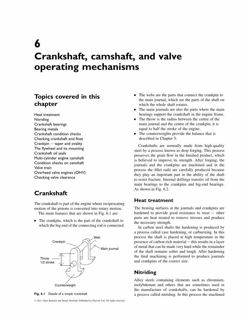
6Crankshaft, camshaft, and valveoperating mechanisms
Topics covered in thischapter
Heat treatmentNitridingCrankshaft bearingsBearing metalsCrankshaft condition checksChecking crankshaft end floatCrankpin e taper and ovalityThe flywheel and its mountingCrankshaft oil sealsMulti-cylinder engine camshaftCondition checks on camshaftValve trainOverhead valve engines (OHV)Checking valve clearance
Crankshaft
The crankshaft is part of the engine where reciprocatingmotion of the pistons is converted into rotary motion.
The main features that are shown in Fig. 6.1 are:
� The crankpin, which is the part of the crankshaft towhich the big end of the connecting rod is connected.
� The webs are the parts that connect the crankpin tothe main journal, which are the parts of the shaft onwhich the whole shaft rotates.
� The main journals are also the parts where the mainbearings support the crankshaft in the engine frame.
� The throw is the radius between the centre of themain journal and the centre of the crankpin; it isequal to half the stroke of the engine.
� The counterweights provide the balance that isdescribed in Chapter 5.
Crankshafts are normally made from high-qualitysteel by a process known as drop forging. This processpreserves the grain flow in the finished product, whichis believed to improve its strength. After forging, thejournals and the crankpins are machined and in theprocess the fillet radii are carefully produced becausethey play an important part in the ability of the shaftto resist fracture. Internal drillings transfer oil from themain bearings to the crankpins and big-end bearings.As shown in Fig. 6.2.
Heat treatment
The bearing surfaces at the journals and crankpins arehardened to provide good resistance to wear e otherparts are heat treated to remove stresses and producethe necessary strength.
In carbon steel shafts the hardening is produced bya process called case hardening, or carburizing. In thisprocess the shaft is placed at high temperature in thepresence of carbon-rich material e this results in a layerof metal that can be made very hard while the remainderof the shaft remains softer and tough. After hardeningthe final machining is performed to produce journalsand crankpins of the correct size.
Nitriding
Alloy steels containing elements such as chromium,molybdenum and others that are sometimes used inthe manufacture of crankshafts, can be hardened bya process called nitriding. In this process the machined
CrankpinWeb
Main journal
Counterweight
Throw1/2 stroke
Fig. 6.1 Details of a simple crankshaft
� 2011 Allan Bonnick and Derek Newbold. Published by Elsevier Ltd. All rights reserved
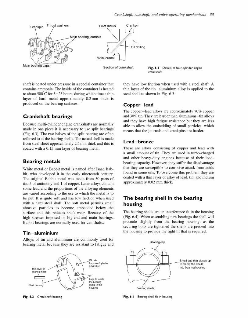
shaft is heated under pressure in a special container thatcontains ammonia. The inside of the container is heatedto about 5008C for 5e25 hours, during which time a thinlayer of hard metal approximately 0.2mm thick isproduced on the bearing surfaces.
Crankshaft bearings
Because multi-cylinder engine crankshafts are normallymade in one piece it is necessary to use split bearings(Fig. 6.3). The two halves of the split bearing are oftenreferred to as the bearing shells. The actual shell is madefrom steel sheet approximately 2.5mm thick and this iscoated with a 0.15 mm layer of bearing metal.
Bearing metals
White metal or Babbit metal is named after Isaac Bab-bit, who developed it in the early nineteenth century.The original Babbit metal was made from 50 parts oftin, 5 of antimony and 1 of copper. Later alloys containsome lead and the proportions of the alloying elementsare varied according to the use to which the metal is tobe put. It is quite soft and has low friction when usedwith a hard steel shaft. The soft metal permits smallabrasive particles to become embedded below thesurface and this reduces shaft wear. Because of thehigh stresses imposed on big-end and main bearings,Babbit bearings are normally used for camshafts.
Tinealuminium
Alloys of tin and aluminium are commonly used forbearing metal because they are resistant to fatigue and
they have low friction when used with a steel shaft. Athin layer of the tinealuminium alloy is applied to thesteel shell as shown in Fig. 6.3.
CoppereleadThe copperelead alloys are approximately 70% copperand 30% tin. They are harder than aluminiumetin alloysand they have high fatigue resistance but they are lessable to allow the embedding of small particles, whichmeans that the journals and crankpins are harder.
Leadebronze
These are alloys consisting of copper and lead witha small amount of tin. They are used in turbo-chargedand other heavy-duty engines because of their load-bearing capacity. However, they suffer the disadvantagethat they are susceptible to corrosive attack from acidsfound in some oils. To overcome this problem they arecoated with a thin layer of alloy of lead, tin, and indiumapproximately 0.02 mm thick.
The bearing shell in the bearinghousing
The bearing shells are an interference fit in the housing(Fig. 6.4). When assembling new bearings the shell willprotrude slightly from the bearing housing; as thesecuring bolts are tightened the shells are pressed intothe housing to provide the tight fit that is required.
Thin layer of bearing metal
Steel backing
Lugs to locatethe bearing shells in thehousing
Oil holefor piston/cylinderlubrication
Fig. 6.3 Crankshaft bearing
Crankpin Thrust washers
Main bearing journals
Main bearing caps
Fillet radius Crankpin
Oil drilling
Main journal
Section of crankshaft Fig. 6.2 Details of four-cylinder engine
crankshaft
Bearing shells
Bearing cap
Small gap that closes upto clamp the shellsinto bearing housing
Fig. 6.4 Bearing shell fit in housing
Crankshaft, camshaft, and valve operating mechanisms 55
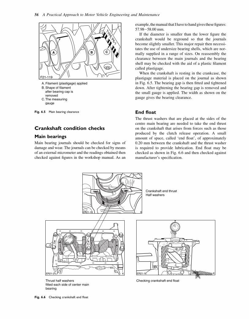
Crankshaft condition checks
Main bearings
Main bearing journals should be checked for signs ofdamage and wear. The journals can be checked by meansof an external micrometer and the readings obtained thenchecked against figures in the workshop manual. As an
example, themanual that I have to handgives thesefigures:57.98e58.00 mm.
If the diameter is smaller than the lower figure thecrankshaft would be reground so that the journalsbecome slightly smaller. This major repair then necessi-tates the use of undersize bearing shells, which are nor-mally supplied in a range of sizes. On reassembly theclearance between the main journals and the bearingshell may be checked with the aid of a plastic filamentcalled plastigage.
When the crankshaft is resting in the crankcase, theplastigage material is placed on the journal as shownin Fig. 6.5. The bearing gap is then fitted and tighteneddown. After tightening the bearing gap is removed andthe small gauge is applied. The width as shown on thegauge gives the bearing clearance.
End float
The thrust washers that are placed at the sides of thecentre main bearing are needed to take the end thruston the crankshaft that arises from forces such as thoseproduced by the clutch release operation. A smallamount of space, called ‘end float’, of approximately0.20 mm between the crankshaft and the thrust washeris required to provide lubrication. End float may bechecked as shown in Fig. 6.6 and then checked againstmanufacturer’s specification.
A B C
F21-119
TYPE P6-1
A. Filament (plastigage) appliedB. Shape of filament after bearing cap is removedC. The measuring gauge
Fig. 6.5 Main bearing clearance
F C R
Checking crankshaft end floatThrust half washersfitted each side of center mainbearing
Crankshaft end thrust Half washers
ER21-16ER21-21 K
K
K
ER21-10
Fig. 6.6 Checking crankshaft end float
56 A Practical Approach to Motor Vehicle Engineering and Maintenance
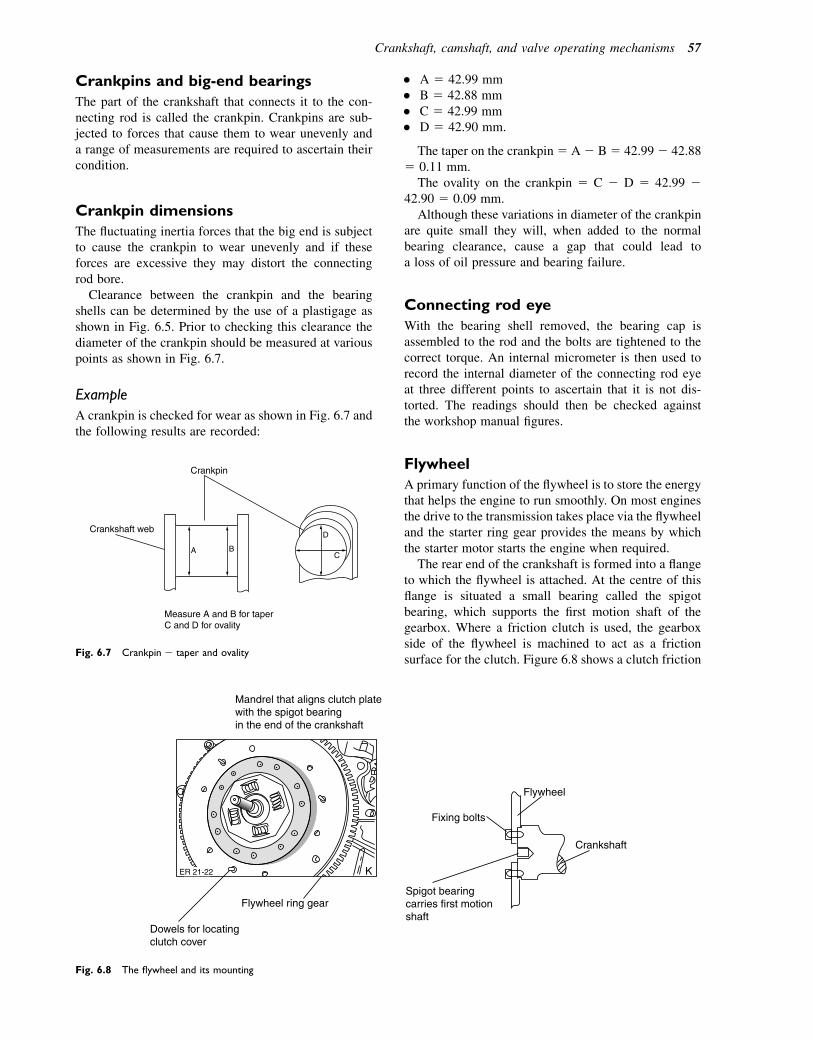
Crankpins and big-end bearings
The part of the crankshaft that connects it to the con-necting rod is called the crankpin. Crankpins are sub-jected to forces that cause them to wear unevenly anda range of measurements are required to ascertain theircondition.
Crankpin dimensions
The fluctuating inertia forces that the big end is subjectto cause the crankpin to wear unevenly and if theseforces are excessive they may distort the connectingrod bore.
Clearance between the crankpin and the bearingshells can be determined by the use of a plastigage asshown in Fig. 6.5. Prior to checking this clearance thediameter of the crankpin should be measured at variouspoints as shown in Fig. 6.7.
Example
A crankpin is checked for wear as shown in Fig. 6.7 andthe following results are recorded:
� A 5 42.99 mm� B 5 42.88 mm� C 5 42.99 mm� D 5 42.90 mm.
The taper on the crankpin5 A2 B5 42.992 42.885 0.11 mm.
The ovality on the crankpin 5 C 2 D 5 42.99 242.90 5 0.09 mm.
Although these variations in diameter of the crankpinare quite small they will, when added to the normalbearing clearance, cause a gap that could lead toa loss of oil pressure and bearing failure.
Connecting rod eye
With the bearing shell removed, the bearing cap isassembled to the rod and the bolts are tightened to thecorrect torque. An internal micrometer is then used torecord the internal diameter of the connecting rod eyeat three different points to ascertain that it is not dis-torted. The readings should then be checked againstthe workshop manual figures.
Flywheel
A primary function of the flywheel is to store the energythat helps the engine to run smoothly. On most enginesthe drive to the transmission takes place via the flywheeland the starter ring gear provides the means by whichthe starter motor starts the engine when required.
The rear end of the crankshaft is formed into a flangeto which the flywheel is attached. At the centre of thisflange is situated a small bearing called the spigotbearing, which supports the first motion shaft of thegearbox. Where a friction clutch is used, the gearboxside of the flywheel is machined to act as a frictionsurface for the clutch. Figure 6.8 shows a clutch friction
A B
Crankshaft web
Crankpin
Measure A and B for taperC and D for ovality
D
C
Fig. 6.7 Crankpin e taper and ovality
Fixing bolts
Mandrel that aligns clutch platewith the spigot bearingin the end of the crankshaft
Flywheel
Crankshaft
Spigot bearingcarries first motionshaft
Flywheel ring gear
K
Dowels for locatingclutch cover
ER 21-22
Fig. 6.8 The flywheel and its mounting
Crankshaft, camshaft, and valve operating mechanisms 57
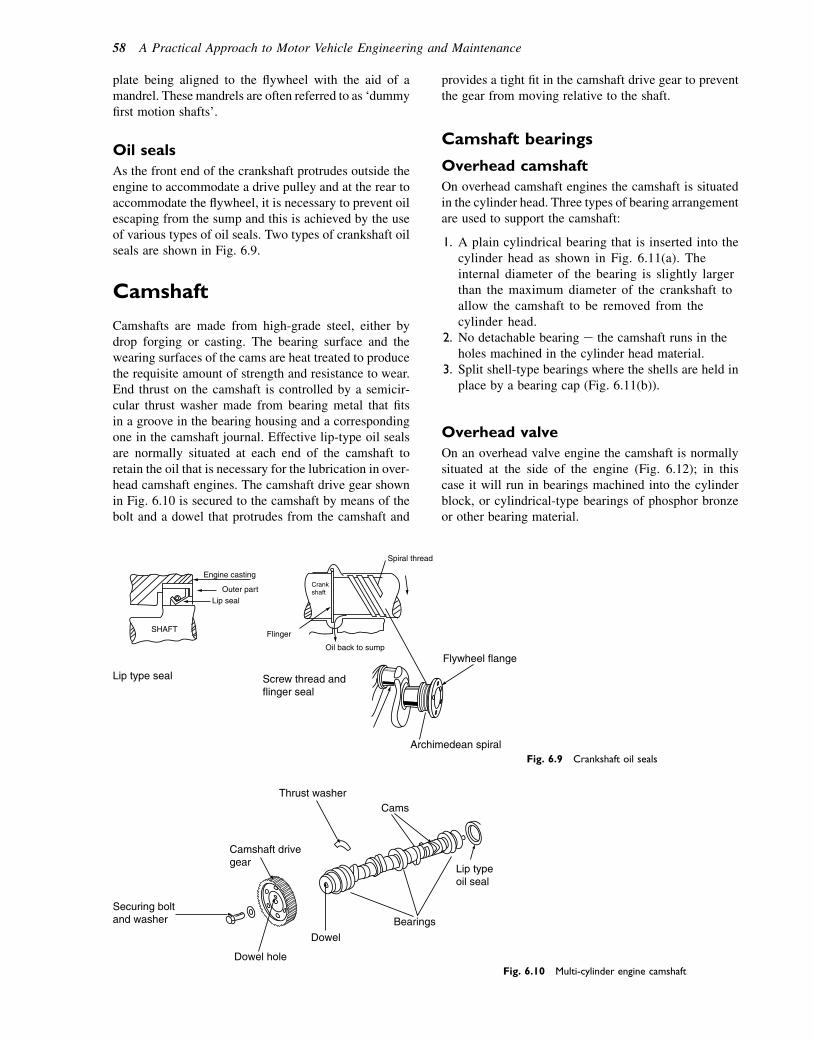
plate being aligned to the flywheel with the aid of amandrel. These mandrels are often referred to as ‘dummyfirst motion shafts’.
Oil seals
As the front end of the crankshaft protrudes outside theengine to accommodate a drive pulley and at the rear toaccommodate the flywheel, it is necessary to prevent oilescaping from the sump and this is achieved by the useof various types of oil seals. Two types of crankshaft oilseals are shown in Fig. 6.9.
Camshaft
Camshafts are made from high-grade steel, either bydrop forging or casting. The bearing surface and thewearing surfaces of the cams are heat treated to producethe requisite amount of strength and resistance to wear.End thrust on the camshaft is controlled by a semicir-cular thrust washer made from bearing metal that fitsin a groove in the bearing housing and a correspondingone in the camshaft journal. Effective lip-type oil sealsare normally situated at each end of the camshaft toretain the oil that is necessary for the lubrication in over-head camshaft engines. The camshaft drive gear shownin Fig. 6.10 is secured to the camshaft by means of thebolt and a dowel that protrudes from the camshaft and
provides a tight fit in the camshaft drive gear to preventthe gear from moving relative to the shaft.
Camshaft bearings
Overhead camshaft
On overhead camshaft engines the camshaft is situatedin the cylinder head. Three types of bearing arrangementare used to support the camshaft:
1. A plain cylindrical bearing that is inserted into thecylinder head as shown in Fig. 6.11(a). Theinternal diameter of the bearing is slightly largerthan the maximum diameter of the crankshaft toallow the camshaft to be removed from thecylinder head.
2. No detachable bearing e the camshaft runs in theholes machined in the cylinder head material.
3. Split shell-type bearings where the shells are held inplace by a bearing cap (Fig. 6.11(b)).
Overhead valve
On an overhead valve engine the camshaft is normallysituated at the side of the engine (Fig. 6.12); in thiscase it will run in bearings machined into the cylinderblock, or cylindrical-type bearings of phosphor bronzeor other bearing material.
Screw thread andflinger seal
Lip type seal
Flywheel flange
Archimedean spiral
Spiral thread
Oil back to sump
Flinger
Crankshaft
SHAFT
Outer partLip seal
Engine casting
Fig. 6.9 Crankshaft oil seals
Dowel hole
Dowel
Bearings
Lip typeoil seal
CamsThrust washer
Camshaft drivegear
Securing boltand washer
Fig. 6.10 Multi-cylinder engine camshaft
58 A Practical Approach to Motor Vehicle Engineering and Maintenance
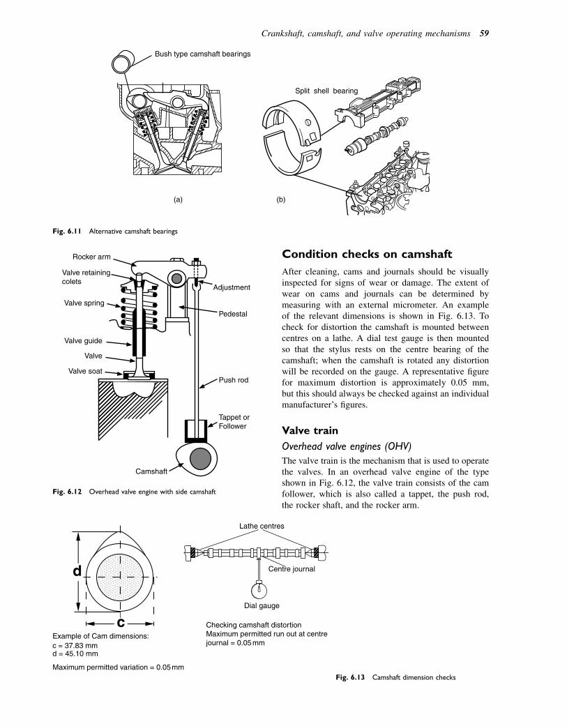
Condition checks on camshaft
After cleaning, cams and journals should be visuallyinspected for signs of wear or damage. The extent ofwear on cams and journals can be determined bymeasuring with an external micrometer. An exampleof the relevant dimensions is shown in Fig. 6.13. Tocheck for distortion the camshaft is mounted betweencentres on a lathe. A dial test gauge is then mountedso that the stylus rests on the centre bearing of thecamshaft; when the camshaft is rotated any distortionwill be recorded on the gauge. A representative figurefor maximum distortion is approximately 0.05 mm,but this should always be checked against an individualmanufacturer’s figures.
Valve train
Overhead valve engines (OHV)
The valve train is the mechanism that is used to operatethe valves. In an overhead valve engine of the typeshown in Fig. 6.12, the valve train consists of the camfollower, which is also called a tappet, the push rod,the rocker shaft, and the rocker arm.
Bush type camshaft bearings
(a)
Split shell bearing
(b)
Fig. 6.11 Alternative camshaft bearings
Adjustment
Pedestal
Push rod
Tappet orFollower
Camshaft
Valve soat
Valve
Valve guide
Valve spring
Valve retainingcolets
Rocker arm
Fig. 6.12 Overhead valve engine with side camshaft
d
cDial gauge
Maximum permitted variation = 0.05 mm
c = 37.83 mmExample of Cam dimensions:
d = 45.10 mm
Centre journal
Lathe centres
Checking camshaft distortionMaximum permitted run out at centrejournal = 0.05 mm
Fig. 6.13 Camshaft dimension checks
Crankshaft, camshaft, and valve operating mechanisms 59
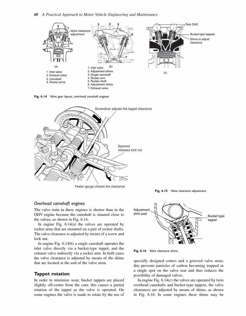
Overhead camshaft engines
The valve train in these engines is shorter than in theOHV engine because the camshaft is situated close tothe valves, as shown in Fig. 6.14.
In engine Fig. 6.14(a) the valves are operated byrocker arms that are mounted on a pair of rocker shafts.The valve clearance is adjusted by means of a screw andlock nut.
In engine Fig. 6.14(b) a single camshaft operates theinlet valve directly via a bucket-type tappet, and theexhaust valve indirectly via a rocker arm. In both casesthe valve clearance is adjusted by means of the shimsthat are located at the end of the valve stem.
Tappet rotation
In order to minimize wear, bucket tappets are placedslightly off-centre from the cam; this causes a partialrotation of the tappet as the valve is operated. Onsome engines the valve is made to rotate by the use of
specially designed cotters and a grooved valve stem;this prevents particles of carbon becoming trapped ina single spot on the valve seat and thus reduces thepossibility of damaged valves.
In engine Fig. 6.14(c) the valves are operated by twinoverhead camshafts and bucket-type tappets, the valveclearances are adjusted by means of shims, as shownin Fig. 6.16. In some engines these shims may be
1. Inlet valve
Valve clearanceadjustment
3
2
12 3
44 5
6
71
(a) (b)
(c)
1. Inlet valve
Twin OHC
Bucket type tappets
Shims to adjustclearance
2. Exhaust valve
7. Exhaust valve
2. Adjustment shims
6. Adjustment shims
3. Single camshaft4. Rocker arm5. Rocker shaft
3. Camshaft4. Rocker arms
Fig. 6.14 Valve gear layout, overhead camshaft engines
Feeler gauge checks the clearance
Spannerreleases lock nut
Screwdiver adjusts the tappet clearance
Fig. 6.15 Valve clearance adjustment
Bucket typetappet
Adjustmentshim pad
Fig. 6.16 Valve clearance shims
60 A Practical Approach to Motor Vehicle Engineering and Maintenance
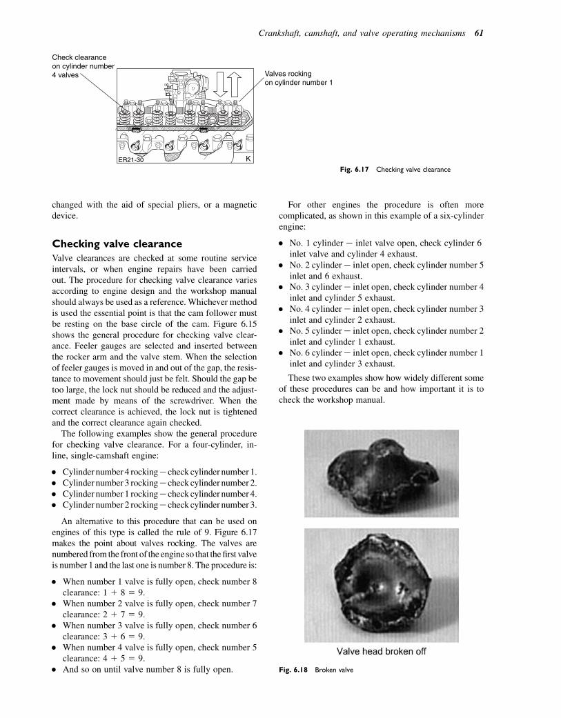
changed with the aid of special pliers, or a magneticdevice.
Checking valve clearance
Valve clearances are checked at some routine serviceintervals, or when engine repairs have been carriedout. The procedure for checking valve clearance variesaccording to engine design and the workshop manualshould always be used as a reference. Whichever methodis used the essential point is that the cam follower mustbe resting on the base circle of the cam. Figure 6.15shows the general procedure for checking valve clear-ance. Feeler gauges are selected and inserted betweenthe rocker arm and the valve stem. When the selectionof feeler gauges is moved in and out of the gap, the resis-tance to movement should just be felt. Should the gap betoo large, the lock nut should be reduced and the adjust-ment made by means of the screwdriver. When thecorrect clearance is achieved, the lock nut is tightenedand the correct clearance again checked.
The following examples show the general procedurefor checking valve clearance. For a four-cylinder, in-line, single-camshaft engine:
� Cylinder number 4 rockinge check cylinder number 1.� Cylinder number 3 rockinge check cylinder number 2.� Cylinder number 1 rockinge check cylinder number 4.� Cylinder number 2 rockinge check cylinder number 3.
An alternative to this procedure that can be used onengines of this type is called the rule of 9. Figure 6.17makes the point about valves rocking. The valves arenumbered from the front of the engine so that thefirst valveis number 1 and the last one is number 8. The procedure is:
� When number 1 valve is fully open, check number 8clearance: 1 1 8 5 9.
� When number 2 valve is fully open, check number 7clearance: 2 1 7 5 9.
� When number 3 valve is fully open, check number 6clearance: 3 1 6 5 9.
� When number 4 valve is fully open, check number 5clearance: 4 1 5 5 9.
� And so on until valve number 8 is fully open.
For other engines the procedure is often morecomplicated, as shown in this example of a six-cylinderengine:
� No. 1 cylinder e inlet valve open, check cylinder 6inlet valve and cylinder 4 exhaust.
� No. 2 cylindere inlet open, check cylinder number 5inlet and 6 exhaust.
� No. 3 cylindere inlet open, check cylinder number 4inlet and cylinder 5 exhaust.
� No. 4 cylindere inlet open, check cylinder number 3inlet and cylinder 2 exhaust.
� No. 5 cylindere inlet open, check cylinder number 2inlet and cylinder 1 exhaust.
� No. 6 cylindere inlet open, check cylinder number 1inlet and cylinder 3 exhaust.
These two examples show how widely different someof these procedures can be and how important it is tocheck the workshop manual.
ER21-30 K
Valves rockingon cylinder number 1
Check clearanceon cylinder number4 valves
Fig. 6.17 Checking valve clearance
Fig. 6.18 Broken valve
Crankshaft, camshaft, and valve operating mechanisms 61

Self-assessment questions1. Figure 6.18 shows the head of a valve that has
broken away from the stem. It is believed that thedamage was caused by the valve hitting the piston.Describe:(a) The valve spring defects that may have caused
the problem.(b) The extent of damage that may have been
caused to other engine components.
2. Name the parts marked A, B and C in Fig. 6.19.What is the purpose of the hole at D?
3. What is the purpose of the seals shown in Fig. 6.20?Why is the exhaust valve seal different to the inletvalve seal?
4. What steps are necessary to ensure that the pistonring is placed at right angles to the cylinder whenchecking the ring gap (Fig. 6.21)? It is recommendedthat the ring gap should be 0.003 3 bore diameter.If the bore diameter is 80 mm what should be thering gap?
A BExhaust valve seal
ER21-197 K
Inlet valve seal
Fig. 6.20 Valve stem seals
B
A
D
C
Fig. 6.19 Engine components
62 A Practical Approach to Motor Vehicle Engineering and Maintenance
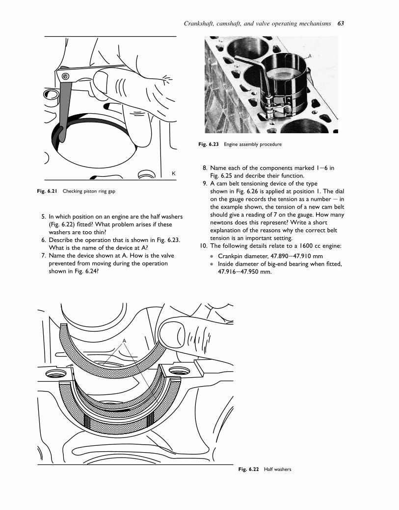
5. In which position on an engine are the half washers(Fig. 6.22) fitted? What problem arises if thesewashers are too thin?
6. Describe the operation that is shown in Fig. 6.23.What is the name of the device at A?
7. Name the device shown at A. How is the valveprevented from moving during the operationshown in Fig. 6.24?
8. Name each of the components marked 1e6 inFig. 6.25 and decribe their function.
9. A cam belt tensioning device of the typeshown in Fig. 6.26 is applied at position 1. The dialon the gauge records the tension as a number e inthe example shown, the tension of a new cam beltshould give a reading of 7 on the gauge. How manynewtons does this represent? Write a shortexplanation of the reasons why the correct belttension is an important setting.
10. The following details relate to a 1600 cc engine:
� Crankpin diameter, 47.890e47.910 mm� Inside diameter of big-end bearing when fitted,
47.916e47.950 mm.
A
Fig. 6.22 Half washers
K
Fig. 6.21 Checking piston ring gap
Fig. 6.23 Engine assembly procedure
Crankshaft, camshaft, and valve operating mechanisms 63
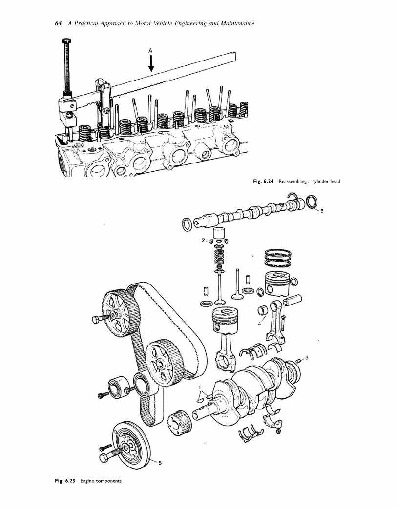
Fig. 6.25 Engine components
Fig. 6.24 Reassembling a cylinder head
64 A Practical Approach to Motor Vehicle Engineering and Maintenance

How big is the bearing clearance when the shaft is at itssmallest diameter and the inside diameter of the bearingis at its maximum value:
(a) 0.060 mm(b) 0.006 mm(c) 0.040 mm(d) 0.400 mm?
11.With the aid of Fig. 6.27, describe how oil reachesthe big-end bearings.
Gauge reading
Cam belt tension gauge
Newtons
1
6
7
5
3
4
2
1
2345679
111315
180220260310350400440530620710800
Fig. 6.26 Cam belt tension
Crankshaft, camshaft, and valve operating mechanisms 65
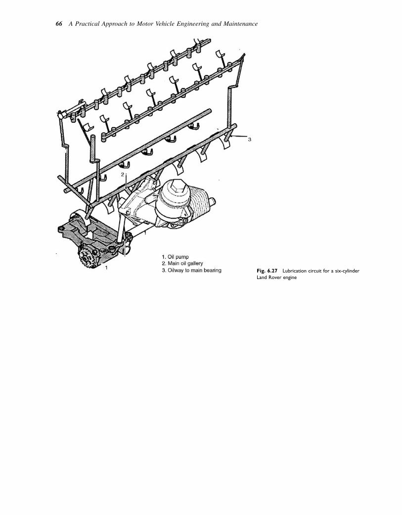
Fig. 6.27 Lubrication circuit for a six-cylinder
Land Rover engine
66 A Practical Approach to Motor Vehicle Engineering and Maintenance
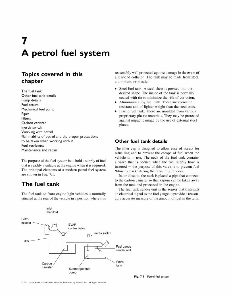
7A petrol fuel system
Topics covered in thischapter
The fuel tankOther fuel tank detailsPump detailsFuel returnMechanical fuel pumpPipesFiltersCarbon canisterInertia switchWorking with petrolFlammability of petrol and the proper precautionsto be taken when working with itFuel retrieversMaintenance and repair
The purpose of the fuel system is to hold a supply of fuelthat is readily available at the engine when it is required.The principal elements of a modern petrol fuel systemare shown in Fig. 7.1.
The fuel tank
The fuel tank on front-engine light vehicles is normallysituated at the rear of the vehicle in a position where it is
reasonably well protected against damage in the event ofa rear-end collision. The tank may be made from steel,aluminium, or plastic:
� Steel fuel tank. A steel sheet is pressed into thedesired shape. The inside of the tank is normallycoated with tin to minimize the risk of corrosion.
� Aluminium alloy fuel tank. These are corrosionresistant and of lighter weight than the steel ones.
� Plastic fuel tank. These are moulded from variousproprietary plastic materials. They may be protectedagainst impact damage by the use of external steelplates.
Other fuel tank details
The filler cap is designed to allow ease of access forrefuelling and to prevent the escape of fuel when thevehicle is in use. The neck of the fuel tank containsa valve that is opened when the fuel supply hose isinserted e the purpose of this valve is to prevent fuel‘blowing back’ during the refuelling process.
In, or close to, the neck is placed a pipe that connectsto the carbon canister so that vapour can be taken awayfrom the tank and processed in the engine.
The fuel tank sender unit is the sensor that transmitsan electrical signal to the fuel gauge to provide a reason-ably accurate measure of the amount of fuel in the tank.
Inertia switch
Fuel gaugesender unit
Petroltank
Submerged fuelpump
Carboncanister
Filter
Petrolinjector
Inletmanifold
EVAPcontrol valve
Fig. 7.1 Petrol fuel system
� 2011 Allan Bonnick and Derek Newbold. Published by Elsevier Ltd. All rights reserved
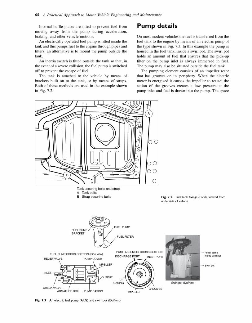
Internal baffle plates are fitted to prevent fuel frommoving away from the pump during acceleration,braking, and other vehicle motions.
An electrically operated fuel pump is fitted inside thetank and this pumps fuel to the engine through pipes andfilters; an alternative is to mount the pump outside thetank.
An inertia switch is fitted outside the tank so that, inthe event of a severe collision, the fuel pump is switchedoff to prevent the escape of fuel.
The tank is attached to the vehicle by means ofbrackets built on to the tank, or by means of straps.Both of these methods are used in the example shownin Fig. 7.2.
Pump details
On most modern vehicles the fuel is transferred from thefuel tank to the engine by means of an electric pump ofthe type shown in Fig. 7.3. In this example the pump ishoused in the fuel tank, inside a swirl pot. The swirl potholds an amount of fuel that ensures that the pick-upfilter on the pump inlet is always immersed in fuel.The pump may also be situated outside the fuel tank.
The pumping element consists of an impeller rotorthat has grooves on its periphery. When the electricmotor is energized it causes the impeller to rotate; theaction of the grooves creates a low pressure at thepump inlet and fuel is drawn into the pump. The space
B
Tank securing bolts and strap.A - Tank boltsB - Strap securing bolts
A
A
Fig. 7.2 Fuel tank fixings (Ford), viewed from
underside of vehicle
FUEL PUMPFUEL PUMPBRACKET
FUEL FILTER
FUEL PUMP CROSS SECTION (Side view)
RELIEF VALVE
INLET
IMPELLER
OUTPUT
CHECK VALVEARMATURE COIL PUMP CASING
CASING
IMPELLER
Swirl pot (DuPont)
Petrol pumpinside swirl pot
Swirl pot
GROOVES
PUMP ASSEMBLY CROSS SECTION
PUMP COVERDISCHARGE PORT INLET PORT
Fig. 7.3 An electric fuel pump (ARG) and swirl pot (DuPont)
68 A Practical Approach to Motor Vehicle Engineering and Maintenance
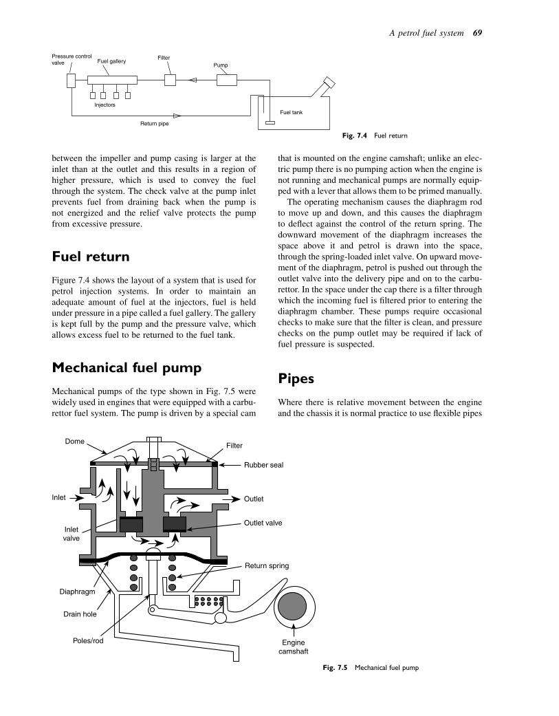
between the impeller and pump casing is larger at theinlet than at the outlet and this results in a region ofhigher pressure, which is used to convey the fuelthrough the system. The check valve at the pump inletprevents fuel from draining back when the pump isnot energized and the relief valve protects the pumpfrom excessive pressure.
Fuel return
Figure 7.4 shows the layout of a system that is used forpetrol injection systems. In order to maintain anadequate amount of fuel at the injectors, fuel is heldunder pressure in a pipe called a fuel gallery. The galleryis kept full by the pump and the pressure valve, whichallows excess fuel to be returned to the fuel tank.
Mechanical fuel pump
Mechanical pumps of the type shown in Fig. 7.5 werewidely used in engines that were equipped with a carbu-rettor fuel system. The pump is driven by a special cam
that is mounted on the engine camshaft; unlike an elec-tric pump there is no pumping action when the engine isnot running and mechanical pumps are normally equip-ped with a lever that allows them to be primed manually.
The operating mechanism causes the diaphragm rodto move up and down, and this causes the diaphragmto deflect against the control of the return spring. Thedownward movement of the diaphragm increases thespace above it and petrol is drawn into the space,through the spring-loaded inlet valve. On upward move-ment of the diaphragm, petrol is pushed out through theoutlet valve into the delivery pipe and on to the carbu-rettor. In the space under the cap there is a filter throughwhich the incoming fuel is filtered prior to entering thediaphragm chamber. These pumps require occasionalchecks to make sure that the filter is clean, and pressurechecks on the pump outlet may be required if lack offuel pressure is suspected.
Pipes
Where there is relative movement between the engineand the chassis it is normal practice to use flexible pipes
Pressure controlvalve Fuel gallery
FilterPump
Fuel tank
Return pipe
Injectors
Fig. 7.4 Fuel return
Dome
Inlet
Diaphragm
Drain hole
Poles/rod
Rubber seal
Filter
Inletvalve
Outlet
Outlet valve
Return spring
Enginecamshaft
Fig. 7.5 Mechanical fuel pump
A petrol fuel system 69
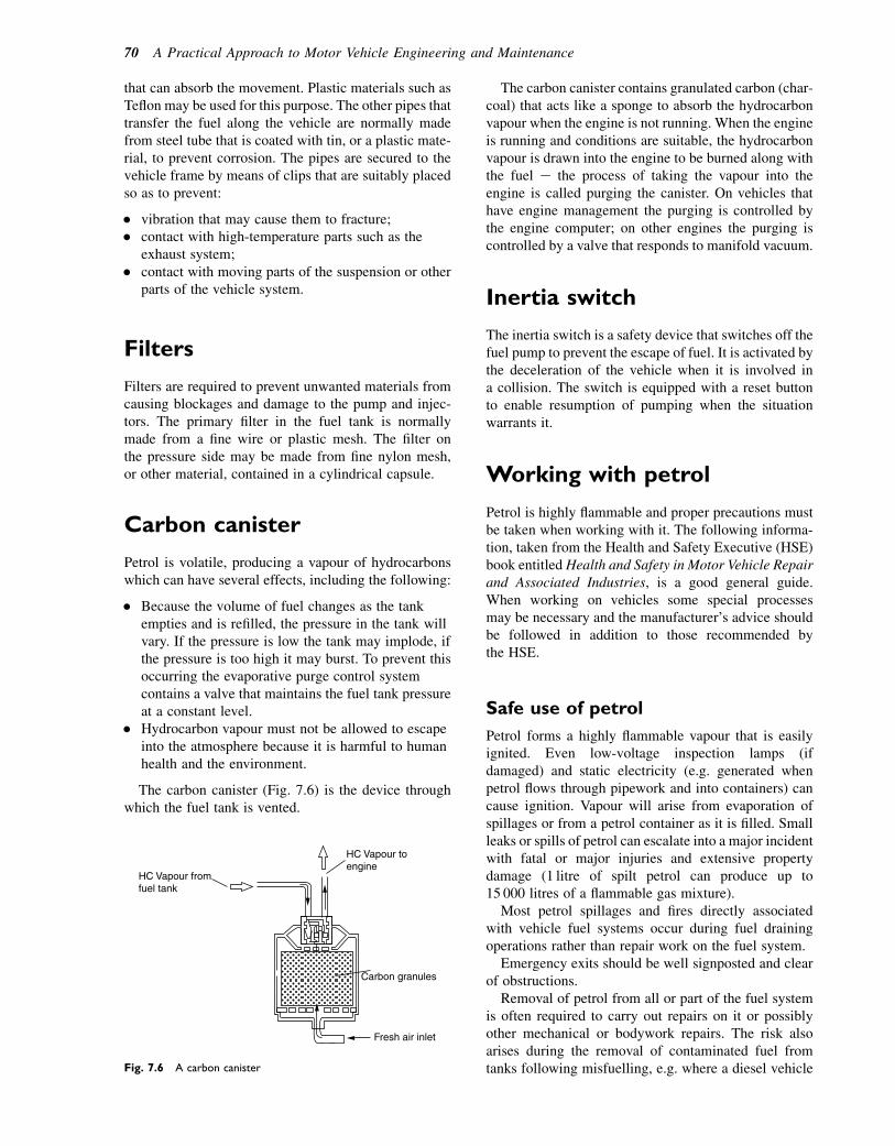
that can absorb the movement. Plastic materials such asTeflon may be used for this purpose. The other pipes thattransfer the fuel along the vehicle are normally madefrom steel tube that is coated with tin, or a plastic mate-rial, to prevent corrosion. The pipes are secured to thevehicle frame by means of clips that are suitably placedso as to prevent:
� vibration that may cause them to fracture;� contact with high-temperature parts such as the
exhaust system;� contact with moving parts of the suspension or other
parts of the vehicle system.
Filters
Filters are required to prevent unwanted materials fromcausing blockages and damage to the pump and injec-tors. The primary filter in the fuel tank is normallymade from a fine wire or plastic mesh. The filter onthe pressure side may be made from fine nylon mesh,or other material, contained in a cylindrical capsule.
Carbon canister
Petrol is volatile, producing a vapour of hydrocarbonswhich can have several effects, including the following:
� Because the volume of fuel changes as the tankempties and is refilled, the pressure in the tank willvary. If the pressure is low the tank may implode, ifthe pressure is too high it may burst. To prevent thisoccurring the evaporative purge control systemcontains a valve that maintains the fuel tank pressureat a constant level.
� Hydrocarbon vapour must not be allowed to escapeinto the atmosphere because it is harmful to humanhealth and the environment.
The carbon canister (Fig. 7.6) is the device throughwhich the fuel tank is vented.
The carbon canister contains granulated carbon (char-coal) that acts like a sponge to absorb the hydrocarbonvapour when the engine is not running. When the engineis running and conditions are suitable, the hydrocarbonvapour is drawn into the engine to be burned along withthe fuel e the process of taking the vapour into theengine is called purging the canister. On vehicles thathave engine management the purging is controlled bythe engine computer; on other engines the purging iscontrolled by a valve that responds to manifold vacuum.
Inertia switch
The inertia switch is a safety device that switches off thefuel pump to prevent the escape of fuel. It is activated bythe deceleration of the vehicle when it is involved ina collision. The switch is equipped with a reset buttonto enable resumption of pumping when the situationwarrants it.
Working with petrol
Petrol is highly flammable and proper precautions mustbe taken when working with it. The following informa-tion, taken from the Health and Safety Executive (HSE)book entitled Health and Safety in Motor Vehicle Repairand Associated Industries, is a good general guide.When working on vehicles some special processesmay be necessary and the manufacturer’s advice shouldbe followed in addition to those recommended bythe HSE.
Safe use of petrol
Petrol forms a highly flammable vapour that is easilyignited. Even low-voltage inspection lamps (ifdamaged) and static electricity (e.g. generated whenpetrol flows through pipework and into containers) cancause ignition. Vapour will arise from evaporation ofspillages or from a petrol container as it is filled. Smallleaks or spills of petrol can escalate into a major incidentwith fatal or major injuries and extensive propertydamage (1 litre of spilt petrol can produce up to15 000 litres of a flammable gas mixture).
Most petrol spillages and fires directly associatedwith vehicle fuel systems occur during fuel drainingoperations rather than repair work on the fuel system.
Emergency exits should be well signposted and clearof obstructions.
Removal of petrol from all or part of the fuel systemis often required to carry out repairs on it or possiblyother mechanical or bodywork repairs. The risk alsoarises during the removal of contaminated fuel fromtanks following misfuelling, e.g. where a diesel vehicle
Fresh air inlet
Carbon granules
HC Vapour toengine
HC Vapour fromfuel tank
Fig. 7.6 A carbon canister
70 A Practical Approach to Motor Vehicle Engineering and Maintenance
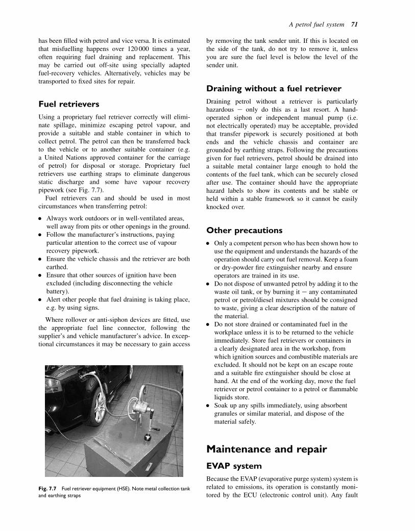
has been filled with petrol and vice versa. It is estimatedthat misfuelling happens over 120 000 times a year,often requiring fuel draining and replacement. Thismay be carried out off-site using specially adaptedfuel-recovery vehicles. Alternatively, vehicles may betransported to fixed sites for repair.
Fuel retrievers
Using a proprietary fuel retriever correctly will elimi-nate spillage, minimize escaping petrol vapour, andprovide a suitable and stable container in which tocollect petrol. The petrol can then be transferred backto the vehicle or to another suitable container (e.g.a United Nations approved container for the carriageof petrol) for disposal or storage. Proprietary fuelretrievers use earthing straps to eliminate dangerousstatic discharge and some have vapour recoverypipework (see Fig. 7.7).
Fuel retrievers can and should be used in mostcircumstances when transferring petrol:
� Always work outdoors or in well-ventilated areas,well away from pits or other openings in the ground.
� Follow the manufacturer’s instructions, payingparticular attention to the correct use of vapourrecovery pipework.
� Ensure the vehicle chassis and the retriever are bothearthed.
� Ensure that other sources of ignition have beenexcluded (including disconnecting the vehiclebattery).
� Alert other people that fuel draining is taking place,e.g. by using signs.
Where rollover or anti-siphon devices are fitted, usethe appropriate fuel line connector, following thesupplier’s and vehicle manufacturer’s advice. In excep-tional circumstances it may be necessary to gain access
by removing the tank sender unit. If this is located onthe side of the tank, do not try to remove it, unlessyou are sure the fuel level is below the level of thesender unit.
Draining without a fuel retriever
Draining petrol without a retriever is particularlyhazardous e only do this as a last resort. A hand-operated siphon or independent manual pump (i.e.not electrically operated) may be acceptable, providedthat transfer pipework is securely positioned at bothends and the vehicle chassis and container aregrounded by earthing straps. Following the precautionsgiven for fuel retrievers, petrol should be drained intoa suitable metal container large enough to hold thecontents of the fuel tank, which can be securely closedafter use. The container should have the appropriatehazard labels to show its contents and be stable orheld within a stable framework so it cannot be easilyknocked over.
Other precautions
� Only a competent person who has been shown how touse the equipment and understands the hazards of theoperation should carry out fuel removal. Keep a foamor dry-powder fire extinguisher nearby and ensureoperators are trained in its use.
� Do not dispose of unwanted petrol by adding it to thewaste oil tank, or by burning it e any contaminatedpetrol or petrol/diesel mixtures should be consignedto waste, giving a clear description of the nature ofthe material.
� Do not store drained or contaminated fuel in theworkplace unless it is to be returned to the vehicleimmediately. Store fuel retrievers or containers ina clearly designated area in the workshop, fromwhich ignition sources and combustible materials areexcluded. It should not be kept on an escape routeand a suitable fire extinguisher should be close athand. At the end of the working day, move the fuelretriever or petrol container to a petrol or flammableliquids store.
� Soak up any spills immediately, using absorbentgranules or similar material, and dispose of thematerial safely.
Maintenance and repair
EVAP system
Because the EVAP (evaporative purge system) system isrelated to emissions, its operation is constantly moni-tored by the ECU (electronic control unit). Any fault
Fig. 7.7 Fuel retriever equipment (HSE). Note metal collection tank
and earthing straps
A petrol fuel system 71
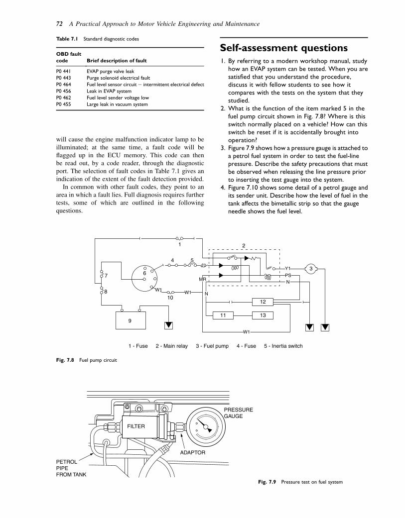
will cause the engine malfunction indicator lamp to beilluminated; at the same time, a fault code will beflagged up in the ECU memory. This code can thenbe read out, by a code reader, through the diagnosticport. The selection of fault codes in Table 7.1 gives anindication of the extent of the fault detection provided.
In common with other fault codes, they point to anarea in which a fault lies. Full diagnosis requires furthertests, some of which are outlined in the followingquestions.
Self-assessment questions1. By referring to a modern workshop manual, study
how an EVAP system can be tested. When you aresatisfied that you understand the procedure,discuss it with fellow students to see how itcompares with the tests on the system that theystudied.
2. What is the function of the item marked 5 in thefuel pump circuit shown in Fig. 7.8? Where is thisswitch normally placed on a vehicle? How can thisswitch be reset if it is accidentally brought intooperation?
3. Figure 7.9 shows how a pressure gauge is attached toa petrol fuel system in order to test the fuel-linepressure. Describe the safety precautions that mustbe observed when releasing the line pressure priorto inserting the test gauge into the system.
4. Figure 7.10 shows some detail of a petrol gauge andits sender unit. Describe how the level of fuel in thetank affects the bimetallic strip so that the gaugeneedle shows the fuel level.
Table 7.1 Standard diagnostic codes
OBD fault
code Brief description of fault
P0 441 EVAP purge valve leak
P0 443 Purge solenoid electrical fault
P0 464 Fuel level sensor circuit e intermittent electrical defect
P0 456 Leak in EVAP system
P0 462 Fuel level sender voltage low
P0 455 Large leak in vacuum system
12
3
2
6
1
4
W1 W1
W1
MRPS
Y1
N
N
5
7
8
13119
1 - Fuse 4 - Fuse 5 - Inertia switch2 - Main relay 3 - Fuel pump
10
Fig. 7.8 Fuel pump circuit
FILTER
ADAPTOR
PRESSUREGAUGE
PETROLPIPEFROM TANK
Fig. 7.9 Pressure test on fuel system
72 A Practical Approach to Motor Vehicle Engineering and Maintenance

5. Figure 7.11 shows some detail of an in-line petrolfilter. What type of pipe connection is shown atposition 2 on the diagram? What type of washeris placed on each side of this connector to ensurethat there are no leaks? Check a service schedulethat you are familiar with and write down therecommended mileage at which the fuel filtershould be renewed.
6. Name some of the positions in the fuel systemwhere flexible pipes are used. What type ofmaterial is used for flexible pipes? How are flexiblepipes secured to the metal pipes?
7. The fuel tank of a petrol engine vehicle isaccidentally topped up with diesel fuel.Describe the procedure for dealing with thisincident. How should the contaminated fuel bedisposed of?
TERMINAL
FLOAT
FE
FLOAT ARM
SLIDINGRESISTOR
VOLTAGEREGULATOR
IGNITIONSWITCH
BIMETALLIC GAUGE
FUEL SENDER GAUGE(SLIDING RESISTOR)
Fig. 7.10 Petrol gauge and sender unit
2
Fig. 7.11 Petrol filter
A petrol fuel system 73

8Motor fuels
Topics covered in thischapter
Calorific valueCombustionProducts of combustion and emissionsHydrocarbon fuelsAlternative sources of energyCatalysts and exhaust after treatmentExhaust gas re-circulationZero emissions vehicles
Most motor fuels and lubricating oils are derived fromcrude oil that comes from oil wells. Crude oil is a finiteresource and various estimates exist about the probablenumber of years that supplies will last. This, coupledwith concern about atmospheric pollution, is a majordriving force behind many of the technological changesin vehicle design. Changes in vehicle design and theever increasing demands from legislators to conserveoil supplies and reduce emissions are challenges thatautomotive service technicians are expected to meeton a daily basis.
Fuels
Calorific value
The calorific value of a fuel is the amount of energy thatis released by the combustion of 1 kg of the fuel. Twofigures for the calorific value of hydrocarbon fuels arenormally quoted: these are the higher or gross calorificvalue, and the lower calorific value. These two valuesarise from the steam that arises from the combustionof hydrogen. The higher calorific value includes theheat of the steam, whereas the lower calorific valueassumes that the heat of the steam is not available todo useful work. The calorific value that is quoted formotor fuels is that which is used in calculations associ-ated with engine and vehicle performance. For example,the calorific value of petrol is approximately 44 MJ/kg.The approximate values of the properties of other fuelsare given in Table 8.1.
Combustion
Fuels for motor vehicles, such as petrol and diesel fuel,are principally hydrocarbons. That is, they consistlargely of the two elements hydrogen and carbon. Theproportions of these elements in the fuel vary, buta reasonably accurate average figure is that motor fuelssuch as petrol and diesel fuel are approximately 85%carbon and 15% hydrogen.
Products of combustion
When considering products of combustion it is useful totake account of some simple chemistry relating to thecombustion equations for carbon and hydrogen. Anadequate supply of oxygen is required to ensurecomplete combustion and this is obtained from theatmospheric air.
The relevant combustion equations are:
For carbon; C1O2 5CO2:
Because of the relative molecular masses of oxygenand carbon, this may be interpreted as: 1 kg of carbonrequires 2.68 kg of oxygen and produces 3.68 kg ofcarbon dioxide when combustion is complete.
For hydrogen; 2H2 1O25 2H2O:
Again, because of the relative molecular masses of Hand O2, this may be interpreted as: 1 kg of hydrogen
Table 8.1 Approximate values of fuel properties
Property LPG Petrol
Diesel
oil Methanol
Relative density 0.55 0.84 0.84 0.8
Usable calorific value
(MJ/kg)
48 44 42.5 20
Octane rating 100 90 e 105
Chemical
composition
82% C,
18% H2
85% C,
15% H2
88% C,
11.5% H2,
0.5% S
38% C,
12% H2,
50% O2
Airefuel ratio 15.5 14.8 14.9 6.5
Mass of CO2 per kg
of fuel used (kg/kg)
3.04 3.2 3.2 1.4
� 2011 Allan Bonnick and Derek Newbold. Published by Elsevier Ltd. All rights reserved
requires 8 kg of oxygen and produces 9 kg of H2O whencombustion is complete.
Airefuel ratio
Petrol has an approximate composition of 15%hydrogen and 85% carbon. The oxygen for combustionis contained in the air supply and approximately 15 kgof air contains the amount of oxygen that will ensurecomplete combustion of 1 kg of petrol. This meansthat the airefuel ratio for complete combustion of petrolis approximately 15:1; a more precise figure is 14.8:1.
Petrol engine combustion
Combustion in spark ignition engines such as the petrolengine is initiated by the spark at the sparking plug andthe burning process is aided by factors such as combus-tion chamber design, temperature in the cylinder,mixture strength, etc.
Because petrol is volatile, each element of the fuel isreadily supplied with sufficient oxygen from theinduced air to ensure complete combustion when thespark occurs. Petrol engine combustion chambers aredesigned so that the combustion that is initiated by thespark at the sparking plug is able to spread uniformlythroughout the combustion chamber.
For normal operation of a petrol engine, a range ofmixture strengths (airefuel ratios) are required fromslightly weak mixtures e say, 20 parts of air to 1 partof petrol for economy cruising, to 10 parts of air to 1part of petrol for cold starting. During normal motoring,a variety of mixture strengths within this range willoccur e for example, acceleration requires approxi-mately 12 parts of air to 1 part of petrol. These varyingconditions plus other factors such as atmospheric condi-tions that affect engine performance lead to variations incombustion efficiency and undesirable combustionproducts known as exhaust emissions are produced.Exhaust emissions and engine performance are affectedby conditions in the combustion chamber. Two effectsthat are associated with combustion in petrol enginesare (1) detonation and (2) pre-ignition.
Detonation
Detonation is characterized by a knocking and loss ofengine performance. The knocking arises after the sparkhas occurred and it is caused by regions of high pressurethat arise when the flame spread throughout the chargein the cylinder is uneven. Uneven flame spread leadsto pockets of high pressure and temperature that causeelements of the charge to burn more rapidly than themain body of the charge. Detonation is influenced byengine design factors such as turbulence, heat flow,combustion chamber shape, etc. Quality of the fuel,including octane rating, also has an effect. Detonation
may lead to increased emissions of CO and NOx (oxidesof nitrogen), and hydrocarbons result.
Pre-ignition
Pre-ignition is characterized by a high pitched ‘pinking’sound that is emitted when combustion prior to the sparkoccurs and it is caused by regions of high temperature.These regions of high temperature may be caused bysparking plug electrodes overheating, sharp or roughedges in the combustion region, carbon deposits, andother factors. In addition to loss of power and mechan-ical damage that may be caused by the high pressuresgenerated by pre-ignition, combustion may be affectedand this will cause harmful exhaust emissions.
Octane rating
The octane rating of a fuel is a measure of the fuel’s resis-tance to knock. A high octane number indicates a highknock resistance. Octane ratings are determined by stan-dard tests in a single-cylinder, variable compression ratioengine. The research octane number (RON) of a fuel isdetermined by running the test engine at a steady 600rpm while the compression ratio is increased until knockoccurs. The motor octane number (MON) is determinedby a similar test, but the engine is operated at higherspeed. The RON is usually higher than the MON andfuel suppliers often quote the RON on their fuel pumps.An alternative rating that is sometimes used gives a figurewhich is the average of RON and MON.
Factors affecting exhaustemissions
During normal operation, the engine of a road vehicle isrequired to operate in a number of quite different modesas follows:
� Idling e slow running� Coasting� Deceleration e overrun braking� Acceleration� Maximum power.
These various modes of operation give rise to varia-tions in pressure, temperature, and mixture strength inthe engine cylinder with the result that exhaustpollutants are produced.
Hydrocarbons (HC)
These appear in the exhaust as a gas arising from incom-plete combustion due to a lack of oxygen. The answer tothis might seem to be to increase the amount of oxygen toweaken the mixture. However, weakening the mixturegives rise to slow burning; combustion will be incomplete
Motor fuels 75
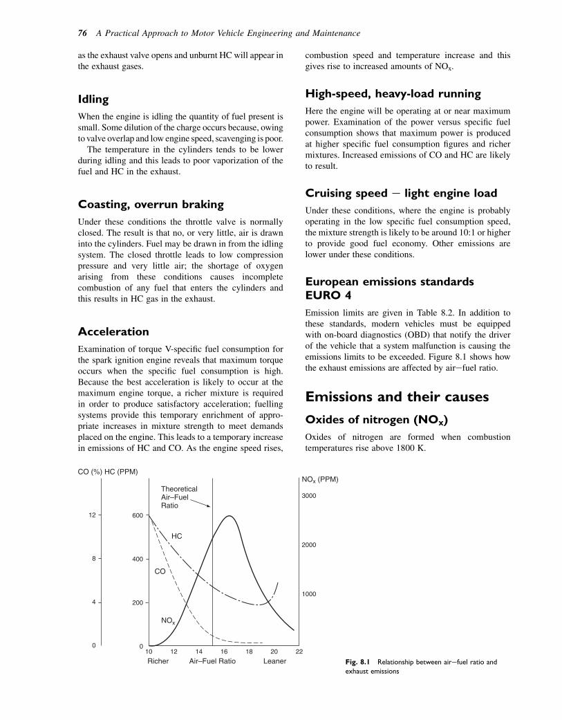
as the exhaust valve opens and unburnt HC will appear inthe exhaust gases.
Idling
When the engine is idling the quantity of fuel present issmall. Some dilution of the charge occurs because, owingto valve overlap and low engine speed, scavenging is poor.
The temperature in the cylinders tends to be lowerduring idling and this leads to poor vaporization of thefuel and HC in the exhaust.
Coasting, overrun braking
Under these conditions the throttle valve is normallyclosed. The result is that no, or very little, air is drawninto the cylinders. Fuel may be drawn in from the idlingsystem. The closed throttle leads to low compressionpressure and very little air; the shortage of oxygenarising from these conditions causes incompletecombustion of any fuel that enters the cylinders andthis results in HC gas in the exhaust.
Acceleration
Examination of torque V-specific fuel consumption forthe spark ignition engine reveals that maximum torqueoccurs when the specific fuel consumption is high.Because the best acceleration is likely to occur at themaximum engine torque, a richer mixture is requiredin order to produce satisfactory acceleration; fuellingsystems provide this temporary enrichment of appro-priate increases in mixture strength to meet demandsplaced on the engine. This leads to a temporary increasein emissions of HC and CO. As the engine speed rises,
combustion speed and temperature increase and thisgives rise to increased amounts of NOx.
High-speed, heavy-load running
Here the engine will be operating at or near maximumpower. Examination of the power versus specific fuelconsumption shows that maximum power is producedat higher specific fuel consumption figures and richermixtures. Increased emissions of CO and HC are likelyto result.
Cruising speed e light engine load
Under these conditions, where the engine is probablyoperating in the low specific fuel consumption speed,the mixture strength is likely to be around 10:1 or higherto provide good fuel economy. Other emissions arelower under these conditions.
European emissions standardsEURO 4
Emission limits are given in Table 8.2. In addition tothese standards, modern vehicles must be equippedwith on-board diagnostics (OBD) that notify the driverof the vehicle that a system malfunction is causing theemissions limits to be exceeded. Figure 8.1 shows howthe exhaust emissions are affected by airefuel ratio.
Emissions and their causes
Oxides of nitrogen (NOx)
Oxides of nitrogen are formed when combustiontemperatures rise above 1800 K.
TheoreticalAir–FuelRatio
CO (%) HC (PPM)
HC
CO
NOx
NOx (PPM)
3000
2000
1000
222018161412100
200
400
60012
8
4
0
Richer Air–Fuel Ratio Leaner Fig. 8.1 Relationship between airefuel ratio and
exhaust emissions
76 A Practical Approach to Motor Vehicle Engineering and Maintenance
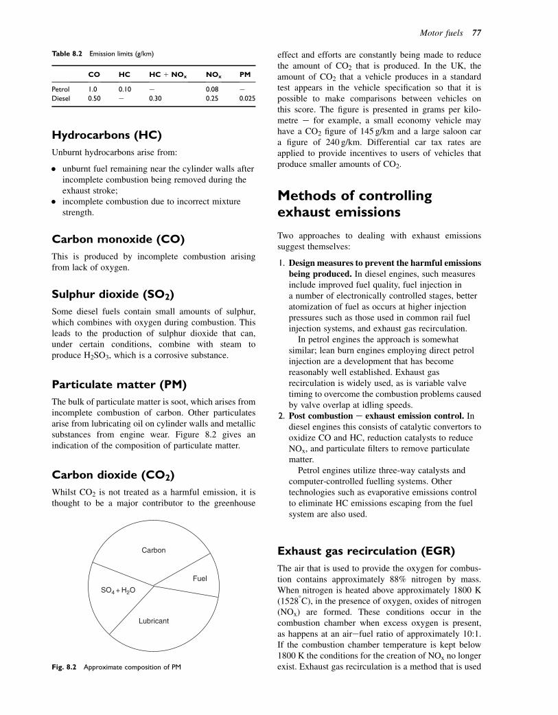
Hydrocarbons (HC)
Unburnt hydrocarbons arise from:
� unburnt fuel remaining near the cylinder walls afterincomplete combustion being removed during theexhaust stroke;
� incomplete combustion due to incorrect mixturestrength.
Carbon monoxide (CO)
This is produced by incomplete combustion arisingfrom lack of oxygen.
Sulphur dioxide (SO2)
Some diesel fuels contain small amounts of sulphur,which combines with oxygen during combustion. Thisleads to the production of sulphur dioxide that can,under certain conditions, combine with steam toproduce H2SO3, which is a corrosive substance.
Particulate matter (PM)
The bulk of particulate matter is soot, which arises fromincomplete combustion of carbon. Other particulatesarise from lubricating oil on cylinder walls and metallicsubstances from engine wear. Figure 8.2 gives anindication of the composition of particulate matter.
Carbon dioxide (CO2)
Whilst CO2 is not treated as a harmful emission, it isthought to be a major contributor to the greenhouse
effect and efforts are constantly being made to reducethe amount of CO2 that is produced. In the UK, theamount of CO2 that a vehicle produces in a standardtest appears in the vehicle specification so that it ispossible to make comparisons between vehicles onthis score. The figure is presented in grams per kilo-metre e for example, a small economy vehicle mayhave a CO2 figure of 145 g/km and a large saloon cara figure of 240 g/km. Differential car tax rates areapplied to provide incentives to users of vehicles thatproduce smaller amounts of CO2.
Methods of controllingexhaust emissions
Two approaches to dealing with exhaust emissionssuggest themselves:
1. Design measures to prevent the harmful emissionsbeing produced. In diesel engines, such measuresinclude improved fuel quality, fuel injection ina number of electronically controlled stages, betteratomization of fuel as occurs at higher injectionpressures such as those used in common rail fuelinjection systems, and exhaust gas recirculation.
In petrol engines the approach is somewhatsimilar; lean burn engines employing direct petrolinjection are a development that has becomereasonably well established. Exhaust gasrecirculation is widely used, as is variable valvetiming to overcome the combustion problems causedby valve overlap at idling speeds.
2. Post combustion e exhaust emission control. Indiesel engines this consists of catalytic convertors tooxidize CO and HC, reduction catalysts to reduceNOx, and particulate filters to remove particulatematter.
Petrol engines utilize three-way catalysts andcomputer-controlled fuelling systems. Othertechnologies such as evaporative emissions controlto eliminate HC emissions escaping from the fuelsystem are also used.
Exhaust gas recirculation (EGR)
The air that is used to provide the oxygen for combus-tion contains approximately 88% nitrogen by mass.When nitrogen is heated above approximately 1800 K(15288C), in the presence of oxygen, oxides of nitrogen(NOx) are formed. These conditions occur in thecombustion chamber when excess oxygen is present,as happens at an airefuel ratio of approximately 10:1.If the combustion chamber temperature is kept below1800 K the conditions for the creation of NOx no longerexist. Exhaust gas recirculation is a method that is used
Carbon
Fuel
Lubricant
SO4 + H2O
Fig. 8.2 Approximate composition of PM
Table 8.2 Emission limits (g/km)
CO HC HC 1 NOx NOx PM
Petrol 1.0 0.10 e 0.08 e
Diesel 0.50 e 0.30 0.25 0.025
Motor fuels 77
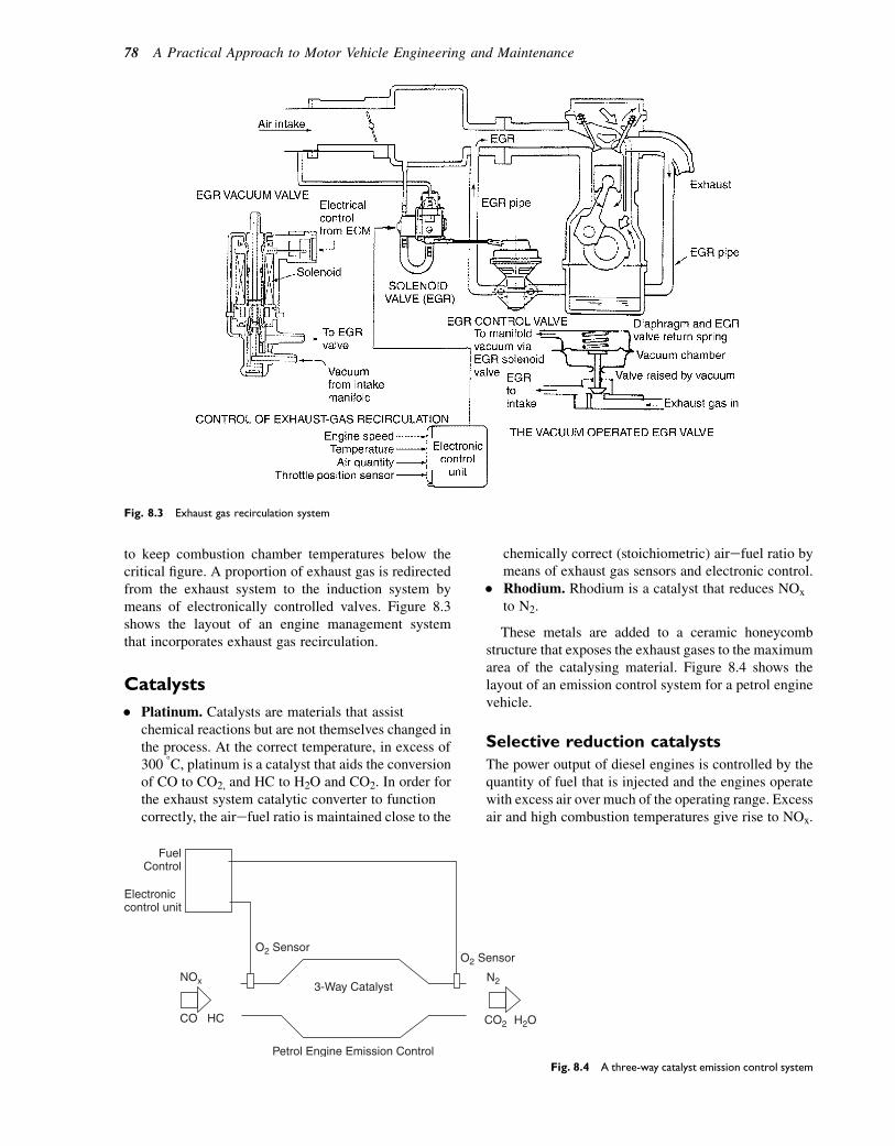
to keep combustion chamber temperatures below thecritical figure. A proportion of exhaust gas is redirectedfrom the exhaust system to the induction system bymeans of electronically controlled valves. Figure 8.3shows the layout of an engine management systemthat incorporates exhaust gas recirculation.
Catalysts
� Platinum. Catalysts are materials that assistchemical reactions but are not themselves changed inthe process. At the correct temperature, in excess of300 8C, platinum is a catalyst that aids the conversionof CO to CO2, and HC to H2O and CO2. In order forthe exhaust system catalytic converter to functioncorrectly, the airefuel ratio is maintained close to the
chemically correct (stoichiometric) airefuel ratio bymeans of exhaust gas sensors and electronic control.
� Rhodium. Rhodium is a catalyst that reduces NOx
to N2.
These metals are added to a ceramic honeycombstructure that exposes the exhaust gases to the maximumarea of the catalysing material. Figure 8.4 shows thelayout of an emission control system for a petrol enginevehicle.
Selective reduction catalysts
The power output of diesel engines is controlled by thequantity of fuel that is injected and the engines operatewith excess air over much of the operating range. Excessair and high combustion temperatures give rise to NOx.
Fig. 8.3 Exhaust gas recirculation system
Fuel Control
Electroniccontrol unit
NOx
CO HC
O2 Sensor O2 Sensor
3-Way Catalyst
CO2 H2O
N2
Petrol Engine Emission Control Fig. 8.4 A three-way catalyst emission control system
78 A Practical Approach to Motor Vehicle Engineering and Maintenance
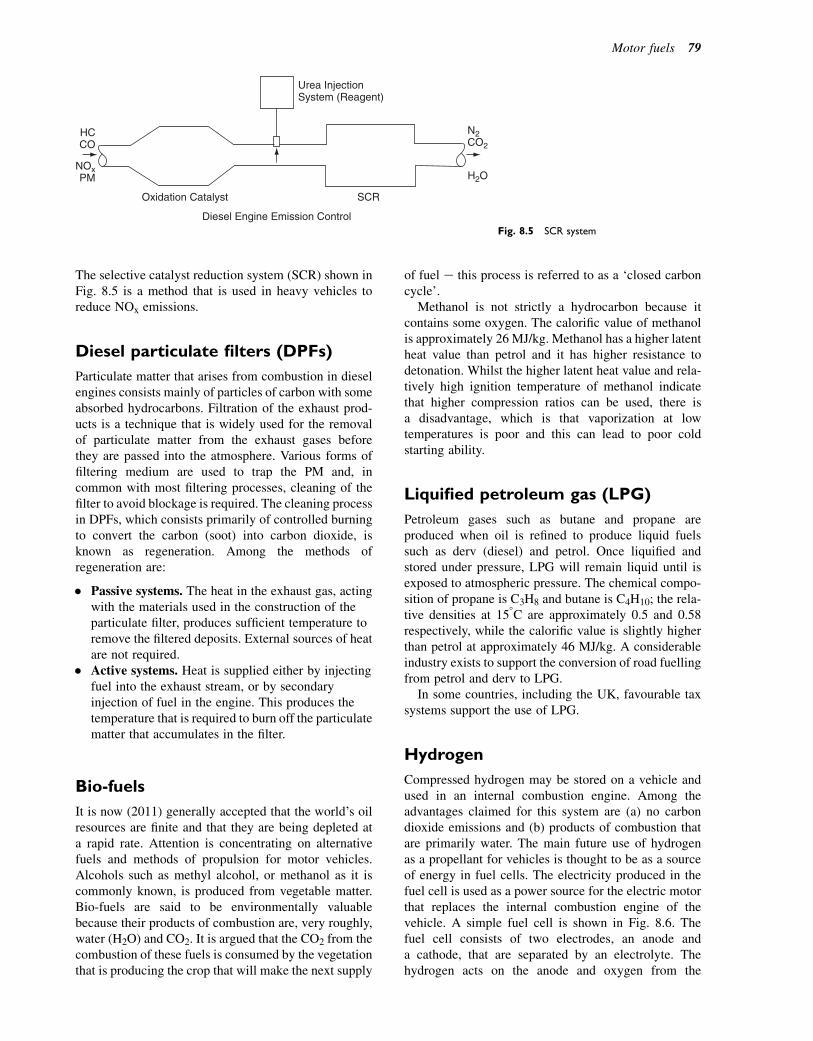
The selective catalyst reduction system (SCR) shown inFig. 8.5 is a method that is used in heavy vehicles toreduce NOx emissions.
Diesel particulate filters (DPFs)
Particulate matter that arises from combustion in dieselengines consists mainly of particles of carbon with someabsorbed hydrocarbons. Filtration of the exhaust prod-ucts is a technique that is widely used for the removalof particulate matter from the exhaust gases beforethey are passed into the atmosphere. Various forms offiltering medium are used to trap the PM and, incommon with most filtering processes, cleaning of thefilter to avoid blockage is required. The cleaning processin DPFs, which consists primarily of controlled burningto convert the carbon (soot) into carbon dioxide, isknown as regeneration. Among the methods ofregeneration are:
� Passive systems. The heat in the exhaust gas, actingwith the materials used in the construction of theparticulate filter, produces sufficient temperature toremove the filtered deposits. External sources of heatare not required.
� Active systems. Heat is supplied either by injectingfuel into the exhaust stream, or by secondaryinjection of fuel in the engine. This produces thetemperature that is required to burn off the particulatematter that accumulates in the filter.
Bio-fuels
It is now (2011) generally accepted that the world’s oilresources are finite and that they are being depleted ata rapid rate. Attention is concentrating on alternativefuels and methods of propulsion for motor vehicles.Alcohols such as methyl alcohol, or methanol as it iscommonly known, is produced from vegetable matter.Bio-fuels are said to be environmentally valuablebecause their products of combustion are, very roughly,water (H2O) and CO2. It is argued that the CO2 from thecombustion of these fuels is consumed by the vegetationthat is producing the crop that will make the next supply
of fuel e this process is referred to as a ‘closed carboncycle’.
Methanol is not strictly a hydrocarbon because itcontains some oxygen. The calorific value of methanolis approximately 26 MJ/kg. Methanol has a higher latentheat value than petrol and it has higher resistance todetonation. Whilst the higher latent heat value and rela-tively high ignition temperature of methanol indicatethat higher compression ratios can be used, there isa disadvantage, which is that vaporization at lowtemperatures is poor and this can lead to poor coldstarting ability.
Liquified petroleum gas (LPG)
Petroleum gases such as butane and propane areproduced when oil is refined to produce liquid fuelssuch as derv (diesel) and petrol. Once liquified andstored under pressure, LPG will remain liquid until isexposed to atmospheric pressure. The chemical compo-sition of propane is C3H8 and butane is C4H10; the rela-tive densities at 158C are approximately 0.5 and 0.58respectively, while the calorific value is slightly higherthan petrol at approximately 46 MJ/kg. A considerableindustry exists to support the conversion of road fuellingfrom petrol and derv to LPG.
In some countries, including the UK, favourable taxsystems support the use of LPG.
Hydrogen
Compressed hydrogen may be stored on a vehicle andused in an internal combustion engine. Among theadvantages claimed for this system are (a) no carbondioxide emissions and (b) products of combustion thatare primarily water. The main future use of hydrogenas a propellant for vehicles is thought to be as a sourceof energy in fuel cells. The electricity produced in thefuel cell is used as a power source for the electric motorthat replaces the internal combustion engine of thevehicle. A simple fuel cell is shown in Fig. 8.6. Thefuel cell consists of two electrodes, an anode anda cathode, that are separated by an electrolyte. Thehydrogen acts on the anode and oxygen from the
HC CO
NOx PM
Oxidation Catalyst
Urea Injection System (Reagent)
N2 CO2
SCR
Diesel Engine Emission Control
H2O
Fig. 8.5 SCR system
Motor fuels 79

atmosphere acts on the cathode. The catalytic action ofthe anode causes the hydrogen atom to form a protonand an electron; the proton passes through the polymerelectrolyte to the cathode and the electron passesthrough an external circuit to the cathode. This actionprovides an electric current in the external circuit. Inthe process the hydrogen and oxygen combine toproduce water, which is the principal emission.
Zero emissions vehicles (ZEVs)
Operation of fuel cells for vehicle propulsion does notinvolve combustion in an engine and the normal prod-ucts of combustion and associated pollutants are notproduced. The main product of the electrochemicalprocesses in the fuel cell is water; consequently, vehi-cles propelled by fuel cells and electric motors areknown as zero emissions vehicles.
Self-assessment questions1. Conduct some research to satisfy yourself about the
effect on fuelling requirements that arise whenconsidering the merits and demerits of convertinga spark ignition engine to run on alcohol fuel. Pay
particular attention to the calorific value and generaleffect on engine performance.
2. A motorist who bought a new car from your garagecomplains that it is using more petrol than he hadanticipated. In the first 2000 miles of use the car hasused 59 gallons of petrol. The advertisement for thecar gave the fuel consumption as 7.5 litres per100 km.(a) Calculate the car’s petrol consumption in mpg
for the first 2000 miles.(b) Convert the mpg figure to litres/100 km.(c) Make a list of the factors that you would discuss
with the customer that might help towards anunderstanding of the difference between theadvertised figure for petrol consumption and theactual figure.
3. A large commercial vehicle returns an average fuelconsumption of 8 mpg and covers 50 000 miles ina year.(a) How many gallons of fuel are used in the year?(b) Calculate the annual cost of fuel at £1.20 per
litre.4. The vehicle in question 3 is fitted with a roof
deflector that improves fuel consumption to 8.15mpg. Calculate the annual saving in fuel cost that isgained by the use of the deflector.
Electrolyte Membrane
e– e–
e–
e– e–
H+
H+
H+ Oxygen O2
Cathode
Water
Anode
Hydrogen H2
H2O
Electrical Power
Fig. 8.6 A simple fuel cell
80 A Practical Approach to Motor Vehicle Engineering and Maintenance
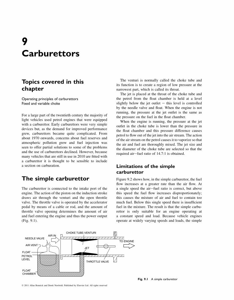
9Carburettors
Topics covered in thischapter
Operating principles of carburettorsFixed and variable choke
For a large part of the twentieth century the majority oflight vehicles used petrol engines that were equippedwith a carburettor. Early carburettors were very simpledevices but, as the demand for improved performancegrew, carburettors became quite complicated. Fromabout 1970 onwards, concerns about fuel reserves andatmospheric pollution grew and fuel injection wasseen to offer partial solutions to some of the problemsand the use of carburettors declined. However, becausemany vehicles that are still in use in 2010 are fitted witha carburettor it is thought to be sensible to includea section on carburation.
The simple carburettor
The carburettor is connected to the intake port of theengine. The action of the piston on the induction strokedraws air through the venturi and the open throttlevalve. The throttle valve is operated by the acceleratorpedal by means of a cable or rod, and the amount ofthrottle valve opening determines the amount of airand fuel entering the engine and thus the power output(Fig. 9.1).
The venturi is normally called the choke tube andits function is to create a region of low pressure at thenarrowest part, which is called its throat.
The jet is placed at the throat of the choke tube andthe petrol from the float chamber is held at a levelslightly below the jet outlet e this level is controlledby the needle valve and float. When the engine is notrunning, the pressure at the jet outlet is the same asthe pressure on the fuel in the float chamber.
When the engine is running, the pressure at the jetoutlet in the choke tube is lower than the pressure inthe float chamber and this pressure difference causespetrol to flow out of the jet into the air stream. The actionof the air stream on the petrol causes it to vaporize so thatthe air and fuel are thoroughly mixed. The jet size andthe diameter of the choke tube are selected so that therequired airefuel ratio of 14.7:1 is obtained.
Limitations of the simplecarburettor
Figure 9.2 shows how, in the simple carburettor, the fuelflow increases at a greater rate than the air flow. Ata single speed the airefuel ratio is correct, but abovethis speed the fuel flow increases disproportionately;this causes the mixture of air and fuel to contain toomuch fuel. Below this single speed there is insufficientfuel in the mixture. The result is that the simple carbu-rettor is only suitable for an engine operating ata constant speed and load. Because vehicle enginesoperate at widely varying speeds and loads, the simple
AIR IN
AIR VENT
FLOAT
PETROL LEVEL
FLOATCHAMBER
THROTTLE VALVE
TO ENGINE
JET
CHOKE TUBE-VENTURI
NEEDLE VALVE
Fig. 9.1 A simple carburettor
� 2011 Allan Bonnick and Derek Newbold. Published by Elsevier Ltd. All rights reserved

carburettor requires certain additions to make it suitablefor use on a vehicle engine.
Rich or weak mixture
The term ‘rich mixture’ describes an airefuel mixturethat has an airefuel ratio smaller than 14.7:1. A ‘weakmixture’ is one in which the airefuel ratio is greaterthan 14.7:1.
Keeping the mixture strengthconstant
Carburettors may be divided into two categories:
1. Constant choke or variable vacuum2. Constant vacuum, variable choke.
Constant-choke carburettor
In the constant-choke carburettor, the airefuel ratio canbe kept near to 14.7:1 by a process known as air bleedcompensation. There are two types of air bleed systems:
1. Diffuser tube2. Compensating jet and well.
Diffuser tube
The diffuser tube (Fig. 9.3) is a small cylinder witha series of holes down its length and it is situated ina tube that contains petrol up to the level in the floatchamber. When the engine is not running the holes inthe tube are covered by the petrol. When the engine isstarted, petrol is drawn into the venturi via the main
jet e as the engine speed increases, the petrol is drawnoff faster than it can flow through the main jet and thiscauses the fuel level to fall in the tube surrounding thediffuser tube. As the fuel level in the tube falls, holesin the diffuser are uncovered and air enters to mixwith the fuel; this also reduces the ‘suction’ on themain jet. By a suitable matching of main jet size anddiffuser tube dimensions the airefuel ratio can be heldat 14.7:1 for a range of engine speeds.
Compensating jet and well
This system uses two jets: a main jet and a compen-sating jet. The main jet connects to the choke tubeand is not affected by the air bleed system. Thecompensating jet feeds into a fuel passage that isopen to atmospheric pressure through a tube calleda well (Fig. 9.4).
FUELFLOW
AIRFLOW
Air/fuel ratio14.7 to 1 Too much fuel
ENGINE R.P.M.
Not enough fuel
0
Fig. 9.2 Limitations of the simple carburettor
Air inletto diffusertube
Diffuser tube
Main jet
Mixture toengine
Air in
Fig. 9.3 Diffuser tube air bleed compensation
Main jet
Fuel level
Well
Air in
Mixture to engine
Compensating jet
Fig. 9.4 Compensating jet and well
82 A Practical Approach to Motor Vehicle Engineering and Maintenance

When the engine first starts the well is filled up to thelevel of the float chamber, through the compensating jet.As the engine speed increases the fuel is drawn down inthe well e this allows air to enter with the fuel andreduces the flow through the compensating jet. The airentering in this way plus the reduction in flow causedby the pressure difference across the compensating jetmaintains the airefuel ratio at the required 14.7:1, orthereabouts.
Cold starts, idling,progression, andacceleration
In normal use, motor vehicles are required to operateunder a range of conditions and the simple carburettorhas been developed to cope with them.
Cold starts
When the engine is cold the fuel in the mixture condenseson the manifold and other parts so that the mixtureentering the combustion chamber is too weak to ignite.To overcome this problem the simple carburettor isequipped with a choke, or strangler of the type shownin Fig. 9.5. The purpose of this choke is to temporarilyrestrict the air flow to the engine so that a richer mixtureis provided to overcome the problem of condensation.The spindle of the choke flap is placed off-centre sothat the flow of air causes an imbalance to open the choketo prevent the engine from being flooded with fuel once ithas started.
Idling
When the engine is idling the throttle valve is almostclosed and an orifice placed in the carburettor, just belowthe throttle valve, allows the requisite amount of mixtureto flow to the engine. On engines with fixed valve timingthere tends to be an amount of burnt gas in the combus-tion chamber that dilutes the charge of air and fuel. Toovercome this problem the mixture supplied for idlingis normally quite rich and this causes problems withthe emissions. However, this problem is minimized bymaking the engine idle at a fairly high speed. In thesimple carburettor shown in Fig. 9.6 the idle mixtureport is connected to a tube that contains the idling jetand an air jet. These two combined determine the airefuel ratio of the idle mixture. The idle control screwcontrols the quantity of mixture that flows to the engine.
Progression
As the engine speed is increased from idling byopening the throttle, the ‘suction’ over the idling
port decreases the mixture flow. To make the transi-tion from idling to higher speed, a progression holeis situated slightly above the throttle valve and thisallows extra idling mixture to enter to keep the enginerunning smoothly until the main jet becomes fullyoperational.
Acceleration
When the accelerator pedal is pressed promptly there isan inrush of air that raises the pressure in the venturi.This causes a weakening of the mixture that may causethe engine to hesitate. The accelerator pump that is fittedto most carburettors (Fig. 9.7) overcomes this problemand it is designed so that it only works when the throttleis opened rapidly.
Running on
Emission control regulations have caused engines fittedwith carburettors to idle at a fairly high speed and to runon weak mixtures, which means that they operate athigh temperatures. The combination of high idlingspeed and high operating temperature brings about
Air intake
Choke
Throttle
Mixture to engine
Fig. 9.5 The cold start choke valve
Carburettors 83
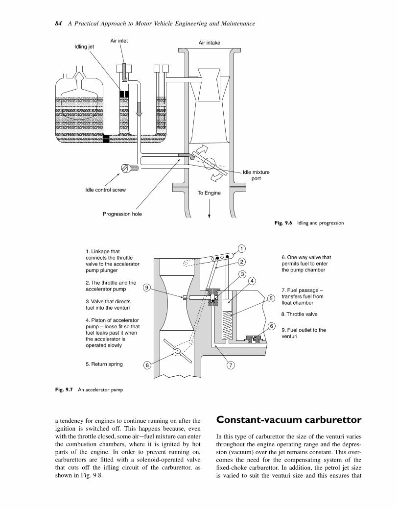
a tendency for engines to continue running on after theignition is switched off. This happens because, evenwith the throttle closed, some airefuel mixture can enterthe combustion chambers, where it is ignited by hotparts of the engine. In order to prevent running on,carburettors are fitted with a solenoid-operated valvethat cuts off the idling circuit of the carburettor, asshown in Fig. 9.8.
Constant-vacuum carburettor
In this type of carburettor the size of the venturi variesthroughout the engine operating range and the depres-sion (vacuum) over the jet remains constant. This over-comes the need for the compensating system of thefixed-choke carburettor. In addition, the petrol jet sizeis varied to suit the venturi size and this ensures that
1
2
34
6
78
9
5
1. Linkage thatconnects the throttlevalve to the acceleratorpump plunger
2. The throttle and theaccelerator pump
3. Valve that directsfuel into the venturi
4. Piston of acceleratorpump – loose fit so thatfuel leaks past it whenthe accelerator isoperated slowly
5. Return spring
6. One way valve thatpermits fuel to enterthe pump chamber
7. Fuel passage – transfers fuel fromfloat chamber
9. Fuel outlet to theventuri
8. Throttle valve
Fig. 9.7 An accelerator pump
Air intakeAir inletIdling jet
To Engine
Idle mixtureport
Idle control screw
Progression hole
Fig. 9.6 Idling and progression
84 A Practical Approach to Motor Vehicle Engineering and Maintenance
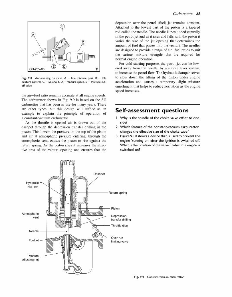
the airefuel ratio remains accurate at all engine speeds.The carburettor shown in Fig. 9.9 is based on the SUcarburettor that has been in use for many years. Thereare other types, but this design will suffice as anexample to explain the principle of operation ofa constant-vacuum carburettor.
As the throttle is opened air is drawn out of thedashpot through the depression transfer drilling in thepiston. This lowers the pressure on the top of the pistonand air at atmospheric pressure entering, through theatmospheric vent, causes the piston to rise against thereturn spring. As the piston rises it increases the effec-tive area of the venturi opening and ensures that the
depression over the petrol (fuel) jet remains constant.Attached to the lowest part of the piston is a taperedrod called the needle. The needle is positioned centrallyin the petrol jet and as it rises and falls with the piston itvaries the size of the jet opening that determines theamount of fuel that passes into the venturi. The needlesare designed to provide a range of airefuel ratios to suitthe various mixture strengths that are required fornormal engine operation.
For cold starting purposes the petrol jet can be low-ered away from the needle, by a simple lever system,to increase the petrol flow. The hydraulic damper servesto slow down the lifting of the piston under engineacceleration and causes a temporary slight mixtureenrichment that helps to reduce hesitation as the enginespeed increases.
Self-assessment questions1. Why is the spindle of the choke valve offset to one
side?2. Which feature of the constant-vacuum carburettor
changes the effective size of the choke tube?3. Figure 9.10 shows a device that is used to prevent the
engine ‘running on’ after the ignition is switched off.What is the position of the valve E when the engine isswitched on?
A
B
DE
C
OR-23V-06
Fig. 9.8 Anti-running on valve. A e Idle mixture port. B e Idle
mixture control. C e Solenoid. D e Mixture space. E e Mixture cut-
off valve
Hydraulicdamper
Mixtureadjusting nut
Fuel jet
Needle
Dashpot
Piston
Return spring
Depressiontransfer drilling
Throttle disc
Over-runlimiting valve
Atmosphericvent
Fig. 9.9 Constant-vacuum carburettor
Carburettors 85

4. What device is incorporated into a fixed-chokecarburettor to provide mixture enrichment foracceleration?
5. What effect on the exhaust gas CO content does theidle mixture control screw have? How does thissystem of idle mixture control vary from the oneshown in Fig. 9.11?
6. What is meant by the term ‘compensation’ in relationto a carburettor? Describe how a carburettorovercomes the problem of the mixture strengthbecoming too rich as the engine speed increases.
7. What is a carburettor venturi? How does it createa region of low pressure?
Idle airAir intake
To Engine
Idle mixture control screw
Idle mixture passage
Fig. 9.11 Idle mixture control
A
B
DE
C
OR-23V-06
Fig. 9.10 Anti-running on valve
86 A Practical Approach to Motor Vehicle Engineering and Maintenance

10Petrol injection e introduction
Topics covered in thischapter
Petrol injection systemsSingle-point injectionMulti-point injectionDirect petrol injectionFuel system maintenance and repair
Modern petrol injection systems are designed to ensurethat the engine extracts the maximum possible amountof energy from each gram of fuel and produces theminimum possible amount of harmful emissions in theprocess. In order to achieve these objectives petrol fuel-ling systems are controlled electronically by a centralcomputer that is called an ECU (electronic control unit).
A principal aim of the fuel and air system is to ensurethat each small particle of fuel is surrounded by sufficientair to provide the oxygen that is required for completecombustion, so that the range of airefuel ratios ofapproximately 10:1 to 20:1 is provided to meet all engineoperating conditions. In petrol injection systems the mix-ing of air and fuel is achieved by spraying the fuel intothe air stream as it enters the induction system, whereasin engines fitted with a carburettor the air and fuel aremixed in the venturi (choke tube) of the carburettor.
Petrol injection systemsThe principle
A simple petrol injection system is shown in Fig. 10.1.The main components are as follows:
1. The air-flow meter produces an electrical signal,usually a voltage, that exactly represents the amountof air that is flowing to the engine. This signal is sentto the ECU.
2. The throttle valve controls the amount of air flowingand it also produces an electrical signal that is sent tothe ECU.
3. The petrol pump supplies petrol at a constantpressure to the injector.
4. The fuel filter ensures that the petrol is clean when itreaches the injector.
5. The petrol injector produces a fine spray of petrolthat is sprayed into the air stream to ensure that airand fuel are mixed.
6. The ECU is a computer that is programmed to holdthe injector open for sufficient time to ensure that theamount of fuel injected corresponds to the air flow sothat the correct airefuel ratio is preserved. Part of theprogram in the computer is a fuelling map e the mapis a section of program that tells the computer howlong to hold the injector open because the amount offuel injected is determined by this period of time.
Air
6
1 2
5
4
3
Petroltank
1. Air flow meter. 2. Throttle valve. 3. Petrol pump.
4. Fuel filter. 5. Petrol injector. 6. Electronic control unit.Fig. 10.1 A simple petrol injection system
� 2011 Allan Bonnick and Derek Newbold. Published by Elsevier Ltd. All rights reserved
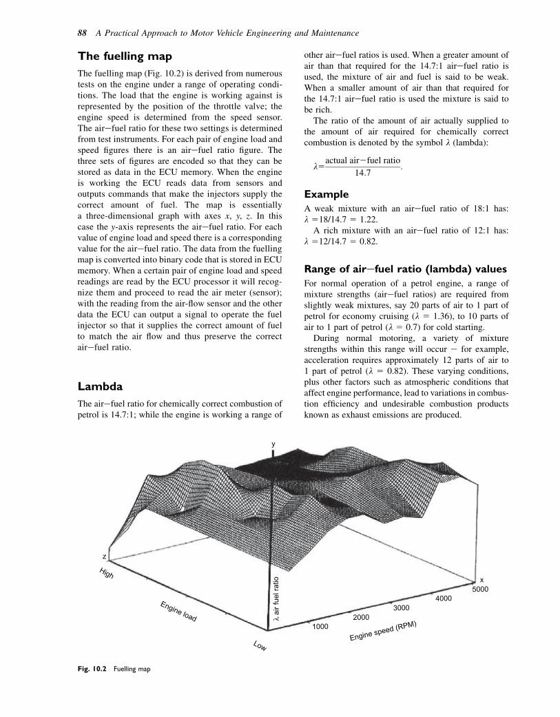
The fuelling map
The fuelling map (Fig. 10.2) is derived from numeroustests on the engine under a range of operating condi-tions. The load that the engine is working against isrepresented by the position of the throttle valve; theengine speed is determined from the speed sensor.The airefuel ratio for these two settings is determinedfrom test instruments. For each pair of engine load andspeed figures there is an airefuel ratio figure. Thethree sets of figures are encoded so that they can bestored as data in the ECU memory. When the engineis working the ECU reads data from sensors andoutputs commands that make the injectors supply thecorrect amount of fuel. The map is essentiallya three-dimensional graph with axes x, y, z. In thiscase the y-axis represents the airefuel ratio. For eachvalue of engine load and speed there is a correspondingvalue for the airefuel ratio. The data from the fuellingmap is converted into binary code that is stored in ECUmemory. When a certain pair of engine load and speedreadings are read by the ECU processor it will recog-nize them and proceed to read the air meter (sensor);with the reading from the air-flow sensor and the otherdata the ECU can output a signal to operate the fuelinjector so that it supplies the correct amount of fuelto match the air flow and thus preserve the correctairefuel ratio.
Lambda
The airefuel ratio for chemically correct combustion ofpetrol is 14.7:1; while the engine is working a range of
other airefuel ratios is used. When a greater amount ofair than that required for the 14.7:1 airefuel ratio isused, the mixture of air and fuel is said to be weak.When a smaller amount of air than that required forthe 14.7:1 airefuel ratio is used the mixture is said tobe rich.
The ratio of the amount of air actually supplied tothe amount of air required for chemically correctcombustion is denoted by the symbol l (lambda):
l5actual air2fuel ratio
14:7:
Example
A weak mixture with an airefuel ratio of 18:1 has:l 518/14.7 5 1.22.
A rich mixture with an airefuel ratio of 12:1 has:l 512/14.7 5 0.82.
Range of airefuel ratio (lambda) values
For normal operation of a petrol engine, a range ofmixture strengths (airefuel ratios) are required fromslightly weak mixtures, say 20 parts of air to 1 part ofpetrol for economy cruising (l 5 1.36), to 10 parts ofair to 1 part of petrol (l 5 0.7) for cold starting.During normal motoring, a variety of mixture
strengths within this range will occur e for example,acceleration requires approximately 12 parts of air to1 part of petrol (l 5 0.82). These varying conditions,plus other factors such as atmospheric conditions thataffect engine performance, lead to variations in combus-tion efficiency and undesirable combustion productsknown as exhaust emissions are produced.
z
x
y
High
Low
1000
air f
uel r
atio
20003000
40005000
Engine speed (RPM)
Engine load
Fig. 10.2 Fuelling map
88 A Practical Approach to Motor Vehicle Engineering and Maintenance

Types of petrol injectionsystem
There are three types of petrol injection in use onmodern petrol engine vehicles (see Fig. 10.3):
� Single-point injection e sometimes called throttlebody injection.
� Multi-point injection e where there is an injector foreach cylinder.
� Direct injection e fuel is injected directly into thecylinders.
Feedback or open loop
In the earlier forms of petrol injection there was no feed-back to tell the computer if anything was not working
properly and this proved to be a problem from the pointof view of controlling emissions. Systems that do nothave feedback are called ‘open-loop’ systems. Withthe introduction of emission control regulations itbecame necessary to fit sensors that would monitor theengine as it was working and send back information tothe ECU, which would then work out (compute) theremedial action that was required to remedy the situa-tion. Modern systems use feedback in a closed-loopsystem.
Single-point injection
In its simplest form, petrol injection consists of a singleinjector of the type shown in Fig. 10.4(a) that sprayspetrol into the induction manifold above the throttlevalve. Finely atomized fuel is sprayed into the throttle
1
2
Injector
Injector
Intake manifold
Airintake
Airintake
Air intake
Injector
Inlet valve Exhaust valve
Injectorsone per cylinder
Intakemanifold
Cylinders
1
2
(a)
(b)
(c)Fig. 10.3 Types of petrol injection systems: (a) single-point;
(b) multi-point; (c) direct injection
Petrol injection e introduction 89
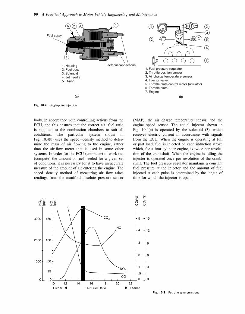
body, in accordance with controlling actions from theECU, and this ensures that the correct airefuel ratiois supplied to the combustion chambers to suit allconditions. The particular system shown inFig. 10.4(b) uses the speededensity method to deter-mine the mass of air flowing to the engine, ratherthan the air-flow meter that is used in some othersystems. In order for the ECU (computer) to work out(compute) the amount of fuel needed for a given setof conditions, it is necessary for it to have an accuratemeasure of the amount of air entering the engine. Thespeededensity method of measuring air flow takesreadings from the manifold absolute pressure sensor
(MAP), the air charge temperature sensor, and theengine speed sensor. The actual injector shown inFig. 10.4(a) is operated by the solenoid (3), whichreceives electric current in accordance with signalsfrom the ECU. When the engine is operating at fullor part load, fuel is injected on each induction strokewhich, for a four-cylinder engine, is twice per revolu-tion of the crankshaft. When the engine is idling theinjector is operated once per revolution of the crank-shaft. The fuel pressure regulator maintains a constantfuel pressure at the injector and the amount of fuelinjected at each pulse is determined by the length oftime for which the injector is open.
1. Housing2. Fuel duct3. Solenoid4. Jet needle5. O-ring
1
4
5 2 3
Fuel spray
Electrical connections
(a) (b)
1. Fuel pressure regulator2. Throttle position sensor3. Air charge temperature sensor4. Injector valve5. Throttle plate control motor (actuator)6. Throttle plate7. Engine
1
2
3
4
5
6
7
Fig. 10.4 Single-point injection
3000
2000
150
100
50
25
10 12Richer LeanerAir Fuel Ratio
14 16 18 20 22
CO
HC
HC
CO
(%)
CO
2(%
)
[ppm
]
NO
x[p
pm]
CO2
NOX
1000
0 0
5
4
3
2
1
.5
0 0
3
6
9
12
15
Fig. 10.5 Petrol engine emissions
90 A Practical Approach to Motor Vehicle Engineering and Maintenance
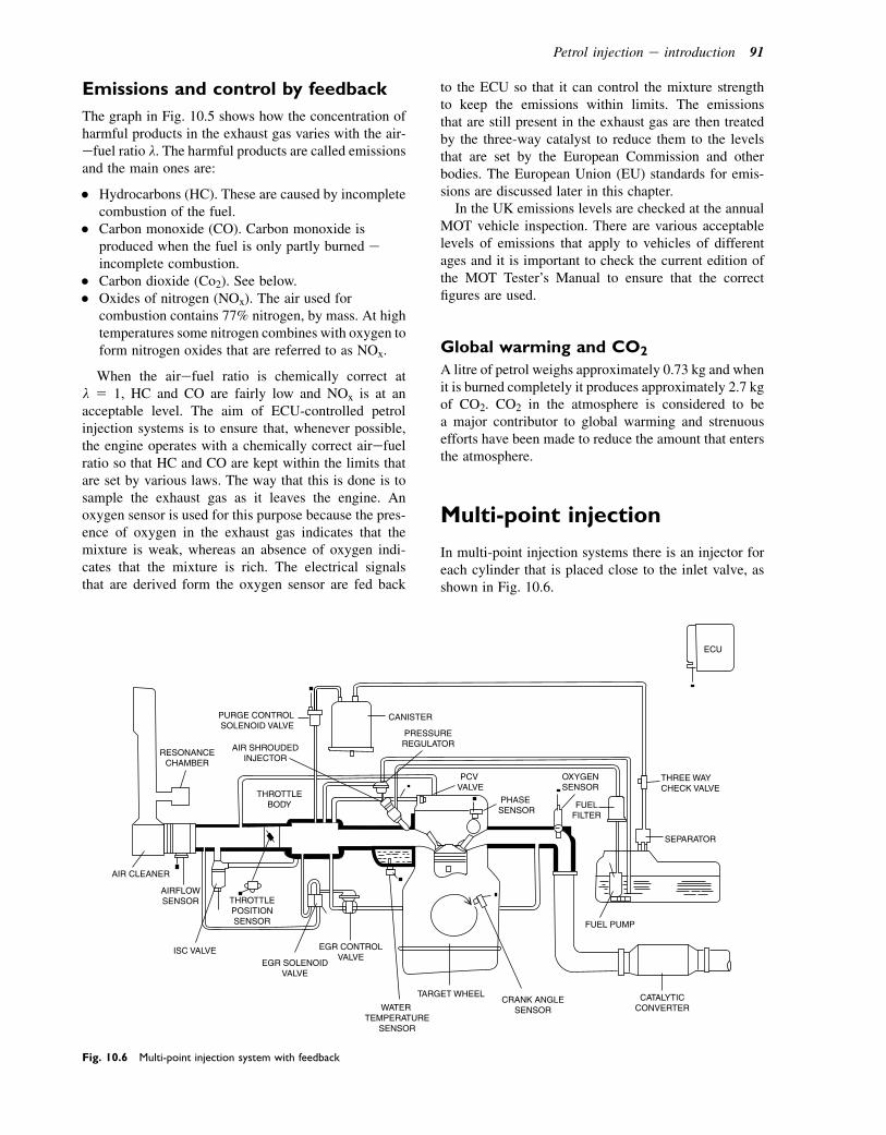
Emissions and control by feedback
The graph in Fig. 10.5 shows how the concentration ofharmful products in the exhaust gas varies with the air-efuel ratio l. The harmful products are called emissionsand the main ones are:
� Hydrocarbons (HC). These are caused by incompletecombustion of the fuel.
� Carbon monoxide (CO). Carbon monoxide isproduced when the fuel is only partly burned eincomplete combustion.
� Carbon dioxide (Co2). See below.� Oxides of nitrogen (NOx). The air used for
combustion contains 77% nitrogen, by mass. At hightemperatures some nitrogen combines with oxygen toform nitrogen oxides that are referred to as NOx.
When the airefuel ratio is chemically correct atl 5 1, HC and CO are fairly low and NOx is at anacceptable level. The aim of ECU-controlled petrolinjection systems is to ensure that, whenever possible,the engine operates with a chemically correct airefuelratio so that HC and CO are kept within the limits thatare set by various laws. The way that this is done is tosample the exhaust gas as it leaves the engine. Anoxygen sensor is used for this purpose because the pres-ence of oxygen in the exhaust gas indicates that themixture is weak, whereas an absence of oxygen indi-cates that the mixture is rich. The electrical signalsthat are derived form the oxygen sensor are fed back
to the ECU so that it can control the mixture strengthto keep the emissions within limits. The emissionsthat are still present in the exhaust gas are then treatedby the three-way catalyst to reduce them to the levelsthat are set by the European Commission and otherbodies. The European Union (EU) standards for emis-sions are discussed later in this chapter.
In the UK emissions levels are checked at the annualMOT vehicle inspection. There are various acceptablelevels of emissions that apply to vehicles of differentages and it is important to check the current edition ofthe MOT Tester’s Manual to ensure that the correctfigures are used.
Global warming and CO2
A litre of petrol weighs approximately 0.73 kg and whenit is burned completely it produces approximately 2.7 kgof CO2. CO2 in the atmosphere is considered to bea major contributor to global warming and strenuousefforts have been made to reduce the amount that entersthe atmosphere.
Multi-point injection
In multi-point injection systems there is an injector foreach cylinder that is placed close to the inlet valve, asshown in Fig. 10.6.
ECU
CANISTER
SEPARATOR
THREE WAYCHECK VALVE
OXYGENSENSOR
FUELFILTER
FUEL PUMP
CATALYTICCONVERTER
TARGET WHEELCRANK ANGLE
SENSORWATER TEMPERATURE
SENSOR
EGR SOLENOIDVALVE
THROTTLEPOSITIONSENSOR
THROTTLEBODY
AIRFLOWSENSOR
AIR SHROUDEDINJECTOR
PURGE CONTROL SOLENOID VALVE
RESONANCECHAMBER
PRESSUREREGULATOR
PCV VALVE
PHASE SENSOR
EGR CONTROLVALVE
ISC VALVE
AIR CLEANER
Fig. 10.6 Multi-point injection system with feedback
Petrol injection e introduction 91

Continuous
In continuous injection systems the injection pulsesoccur on each revolution of the crankshaft, with halfthe required amount of fuel for each cylinder beingdelivered in two stages.
Sequential
In sequential petrol injection systems the injectionpulses take place in the same sequence as the enginefiring order, with the full amount of fuel being deliveredon each induction stroke.
The catalyst and oxygen sensor
A key element in the closed-loop control system is thecatalytic converter in the exhaust system (Fig. 10.7).
The function of the catalyst is to convert CO, NOx andHC into CO2, H2O and N2, and it can only do this if theairefuel ratio l is held between about 0.107 and 1.03.The oxygen sensor is the device that informs the ECUabout the value of l while the engine is running. Theother devices in the petrol injection control systemthen act together with the ECU to ensure that the airefuel ratio l is kept within the limits so that the emissionscontrol system is effective. The catalyst does not func-tion at temperatures below approximately 4008C, whichmeans that the engine only operates in closed-loopcontrol when it is hot enough to do so.
The oxygen sensor
The voltaic oxygen sensor (Fig. 10.8) acts like a smallbattery. It consists of a pair of platinum electrodes thatare separated by a layer of zirconium oxide. Theplatinum electrodes perform two functions:
CO2-H2O-N2
CO-HC-NOx
Case
Catalyst
Exhaust gasesfrom engine
Greatly enlarged sectionof the catalyst
Coated with aluminacontainingPlatinum, Rhodium,Palladium
Ceramic honeycomb
HC + CO + NO 2
Fig. 10.7 Three-way catalytic converter
A = Ambient air; B = Exhaust gases
1. Protective ceramic coating2. Electrodes3. Zirconium oxide
Voltage output fromZirconia sensor
Richer – AIR-FUEL RATIO – Leaner0V
OU
TP
UT
VO
LTA
GE
1V
THEORETICAL AIR-FUEL RATIO
Exhaust gas
O2 Sensor
1
2
3
B
A
v
(a)
(b)
(c)
Fig. 10.8 Voltaic-type oxygen sensor
92 A Practical Approach to Motor Vehicle Engineering and Maintenance
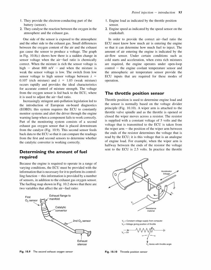
1. They provide the electron-conducting part of thebattery (sensor).
2. They catalyse the reaction between the oxygen in theatmosphere and the exhaust gas.
One side of the sensor is exposed to the atmosphereand the other side to the exhaust gas. Small differencesbetween the oxygen content of the air and the exhaustgas cause the sensor to produce a voltage. The graphin Fig. 10.8(c) shows how there is a sudden change insensor voltage when the airefuel ratio is chemicallycorrect. When the mixture is rich the sensor voltage ishigh e about 800 mV e and when the mixture isweak the sensor voltage is low. The switch from lowsensor voltage to high sensor voltage between l 50.107 (rich mixture) and l 5 1.03 (weak mixture)occurs rapidly and provides the ideal characteristicsfor accurate control of mixture strength. The voltagefrom the oxygen sensor is fed back to the ECU, whereit is used to adjust the airefuel ratio.
Increasingly stringent anti-pollution legislation led tothe introduction of European on-board diagnostics(EOBD); this system requires the ECU to constantlymonitor systems and alert the driver through the enginewarning lamp when a component fails to work correctly.Part of the monitoring system consists of a secondexhaust gas oxygen sensor that is placed downstreamfrom the catalyst (Fig. 10.9). This second sensor feedsback data to the ECU so that it can compare the readingsfrom the first and second sensors to determine whetherthe catalytic converter is working correctly.
Determining the amount of fuelrequired
Because the engine is required to operate in a range ofvarying conditions, the ECU must be provided with theinformation that is necessary for it to perform its control-ling functione this information is provided by a numberof sensors, in addition to the exhaust gas oxygen sensor.The fuelling map shown in Fig. 10.2 shows that there aretwo variables that affect the airefuel ratio:
1. Engine load as indicated by the throttle positionsensor.
2. Engine speed as indicated by the speed sensor on thecrankshaft.
In order to provide the correct airefuel ratio theECU must know how much air is entering the engineso that it can determine how much fuel to inject. Theamount of air entering the engine is indicated by theair-flow sensor. Under certain conditions such ascold starts and acceleration, when extra rich mixturesare required, the engine operates under open-loopcontrol e the engine coolant temperature sensor andthe atmospheric air temperature sensor provide theECU inputs that are required for these modes ofoperation.
The throttle position sensor
Throttle position is used to determine engine load andthe sensor is normally based on the voltage dividerprinciple (Fig. 10.10). A wiper arm is attached to thethrottle valve spindle and as the throttle is opened orclosed the wiper moves across a resistor. The resistoris supplied with a constant voltage of 5 volts and thevoltage that is transmitted to the ECU is taken fromthe wiper arm e the position of the wiper arm betweenthe ends of the resistor determines the voltage that isread by the ECU; it is this voltage that is an analogueof engine load. For example, when the wiper arm ishalfway between the ends of the resistor the voltagesent to the ECU is 2.5 volts. In practice the throttle
Catalyticconvertor
FirstO2 sensor
2nd O2 sensor
Exhaust flange tomanifold
Exhaustsilencer
Fig. 10.9 The second exhaust oxygen sensor
Acceleratorlinkage
Resistancematerial
VP
VC
VC = 5V
VC = Constant voltage supply from computer
VP = Voltage giving position of throttle
VP Varies with throttle angle
Fig. 10.10 Throttle position sensor
Petrol injection e introduction 93
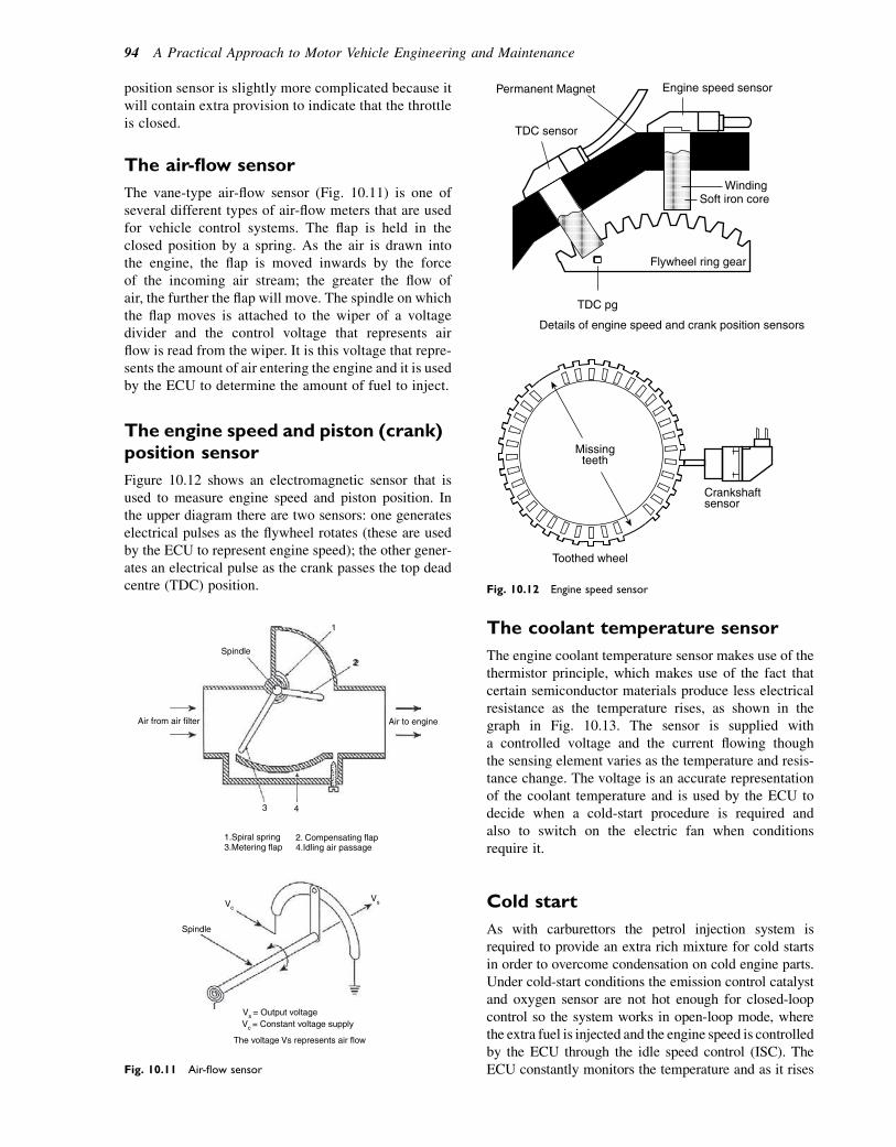
position sensor is slightly more complicated because itwill contain extra provision to indicate that the throttleis closed.
The air-flow sensor
The vane-type air-flow sensor (Fig. 10.11) is one ofseveral different types of air-flow meters that are usedfor vehicle control systems. The flap is held in theclosed position by a spring. As the air is drawn intothe engine, the flap is moved inwards by the forceof the incoming air stream; the greater the flow ofair, the further the flap will move. The spindle on whichthe flap moves is attached to the wiper of a voltagedivider and the control voltage that represents airflow is read from the wiper. It is this voltage that repre-sents the amount of air entering the engine and it is usedby the ECU to determine the amount of fuel to inject.
The engine speed and piston (crank)position sensor
Figure 10.12 shows an electromagnetic sensor that isused to measure engine speed and piston position. Inthe upper diagram there are two sensors: one generateselectrical pulses as the flywheel rotates (these are usedby the ECU to represent engine speed); the other gener-ates an electrical pulse as the crank passes the top deadcentre (TDC) position.
The coolant temperature sensor
The engine coolant temperature sensor makes use of thethermistor principle, which makes use of the fact thatcertain semiconductor materials produce less electricalresistance as the temperature rises, as shown in thegraph in Fig. 10.13. The sensor is supplied witha controlled voltage and the current flowing thoughthe sensing element varies as the temperature and resis-tance change. The voltage is an accurate representationof the coolant temperature and is used by the ECU todecide when a cold-start procedure is required andalso to switch on the electric fan when conditionsrequire it.
Cold start
As with carburettors the petrol injection system isrequired to provide an extra rich mixture for cold startsin order to overcome condensation on cold engine parts.Under cold-start conditions the emission control catalystand oxygen sensor are not hot enough for closed-loopcontrol so the system works in open-loop mode, wherethe extra fuel is injected and the engine speed is controlledby the ECU through the idle speed control (ISC). TheECU constantly monitors the temperature and as it rises
Air from air filter
Spindle
Spindle
VcVs
Vc = Constant voltage supply
The voltage Vs represents air flow
Vs = Output voltage
1
22
Air to engine
43
1.Spiral spring3.Metering flap
2. Compensating flap4.Idling air passage
Fig. 10.11 Air-flow sensor
WindingSoft iron core
Permanent Magnet
TDC sensor
Flywheel ring gear
Details of engine speed and crank position sensors
Missingteeth
Toothed wheel
TDC pg
Crankshaftsensor
Engine speed sensor
Fig. 10.12 Engine speed sensor
94 A Practical Approach to Motor Vehicle Engineering and Maintenance

the airefuel ratio is gradually weakened until the catalystand oxygen sensor are operating normally; at this stagethe ECU takes the system into closed-loop mode.
Idle speed control
When the engine is idling the throttle valve is virtuallyclosed and the idle speed control valve bypasses thethrottle valve to allow sufficient air to keep the enginerunning smoothly. The idle speed valve shown inFig. 10.14 is operated by a small electric motor. Thepartial rotation of the armature of the motor is controlledby the ECU using a process called pulse width modula-tion. As the armature rotates the screw thread raises orlowers the air valve, under the control of the ECU, toensure that the correct amount of air for idling reachesthe combustion chambers.
A petrol injector
Petrol injectors are operated by an electromagneticdevice called a solenoid. The ECU controls a transistoras shown in Fig. 10.15(b) that is used to switch theinjector on and off as required. Because the fuel at the
injector is held at constant pressure the amount offuel injected is determined by the length of time forwhich the injector is switched on. The nozzle of theinjector is designed to ensure that the fuel is injectedinto the air stream as fine spray. The main parts ofa petrol injector are shown in Fig. 10.15(a). The arma-ture and nozzle valve are pulled inside the solenoidcoil when the injector is switched on; when the currentis switched off the armature and nozzle valve arereturned to the closed position by the return spring.
Duty cycle
The maximum time for which the injector can beswitched on is denoted by the distance C inFig. 10.16. The actual time it is switched on is controlledby the ECU so that the amount of fuel injected is correctfor the conditions at the time. The switched-on time isdenoted by the distance A, which means that the injectoris activated for 25% of the available time, i.e. the dutycycle is 25%. For extra fuel the on time is increased,giving an increase in duty cycle.
Exhaust gas recirculation (EGR)
Although the three-way catalyst reduces NOx tonitrogen (N2) and CO2, it is made more effective if theamount of NOx produced by combustion is reduced.High temperatures in the combustion chamber causethe production of NOx and when calibrated amountsof exhaust gas are recirculated into the induction systemthe combustion chamber temperature is reduced, thusreducing the production of NOx. The exhaust gas recir-culation actuator is controlled by the ECU so thatmeasured amounts of exhaust gas are sent back to theinduction system when engine operating conditionsare suitable e the actual amounts and the conditionsunder which recirculation takes place are determinedby the engine designers.
100
80
60
40
20
0 20 40 60 80 100
Engine coolant temperature (°C)
Sensor element
Electrical connections
The
rmis
tor
resi
stan
ce (
ohm
s x1
03 )
Fig. 10.13 A thermistor-type engine coolant
temperature sensor
Screw thread
Air inlet
Air to engine
Air valve
Armature ofelectric motor
Fig. 10.14 Idle speed control valve (Robert Bosch)
Petrol injection e introduction 95
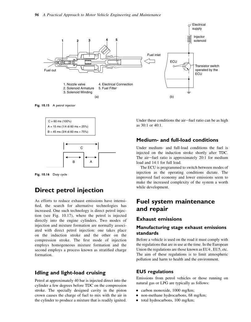
Direct petrol injection
As efforts to reduce exhaust emissions have intensi-fied, the search for alternative technologies hasincreased. One such technology is direct petrol injec-tion (see Fig. 10.17), where the petrol is injecteddirectly into the engine cylinders. Two modes ofinjection and mixture formation are normally associ-ated with direct petrol injection: one takes placeon the induction stroke and the other on thecompression stroke. The first mode of injectionemploys homogeneous mixture formation and thesecond employs a process known as stratified chargeformation.
Idling and light-load cruising
Petrol at approximately 40 bar is injected direct into thecylinder a few degrees before TDC on the compressionstroke. The specially designed cavity in the pistoncrown causes the charge of fuel to mix with the air inthe cylinder to produce a mixture that is readily ignited.
Under these conditions the airefuel ratio can be as highas 30:1 or 40:1.
Medium- and full-load conditions
Under medium- and full-load conditions the fuel isinjected on the induction stroke shortly after TDC.The airefuel ratio is approximately 20:1 for mediumload and 14:1 for full load.
The ECU is programmed to switch between modes ofinjection as the operating conditions dictate. Theimproved fuel economy and lower emissions seem tomake the increased complexity of the system a worthwhile development.
Fuel system maintenanceand repair
Exhaust emissions
Manufacturing stage exhaust emissionsstandards
Before a vehicle is used on the road it must comply withthe regulations that are in use at the time. In the EuropeanUnion the regulations are those known as EU4 , EU5, etc.The aim of these regulations is to limit atmosphericpollution and harm to health and the environment.
EU5 regulations
Emissions from petrol vehicles or those running onnatural gas or LPG are typically as follows:
� carbon monoxide, 1000 mg/km;� non-methane hydrocarbons, 68 mg/km;� total hydrocarbons, 100 mg/km;
1
Fuel out
Fuel inlet
Electricalsupply
Injectorsolenoid
Transistor switchoperated by theECU
ECU
1. Nozzle valve2. Solenoid Armature3. Solenoid Winding
4. Electrical Connection5. Fuel Filter
2
(a) (b)
3 4 5
Fig. 10.15 A petrol injector
C
B A
C = 60 ms (100%)
A = 15 ms (1/4 di 60 ms = 25%)
B = 45 ms (3/4 di 60 ms = 75%)
Fig. 10.16 Duty cycle
96 A Practical Approach to Motor Vehicle Engineering and Maintenance
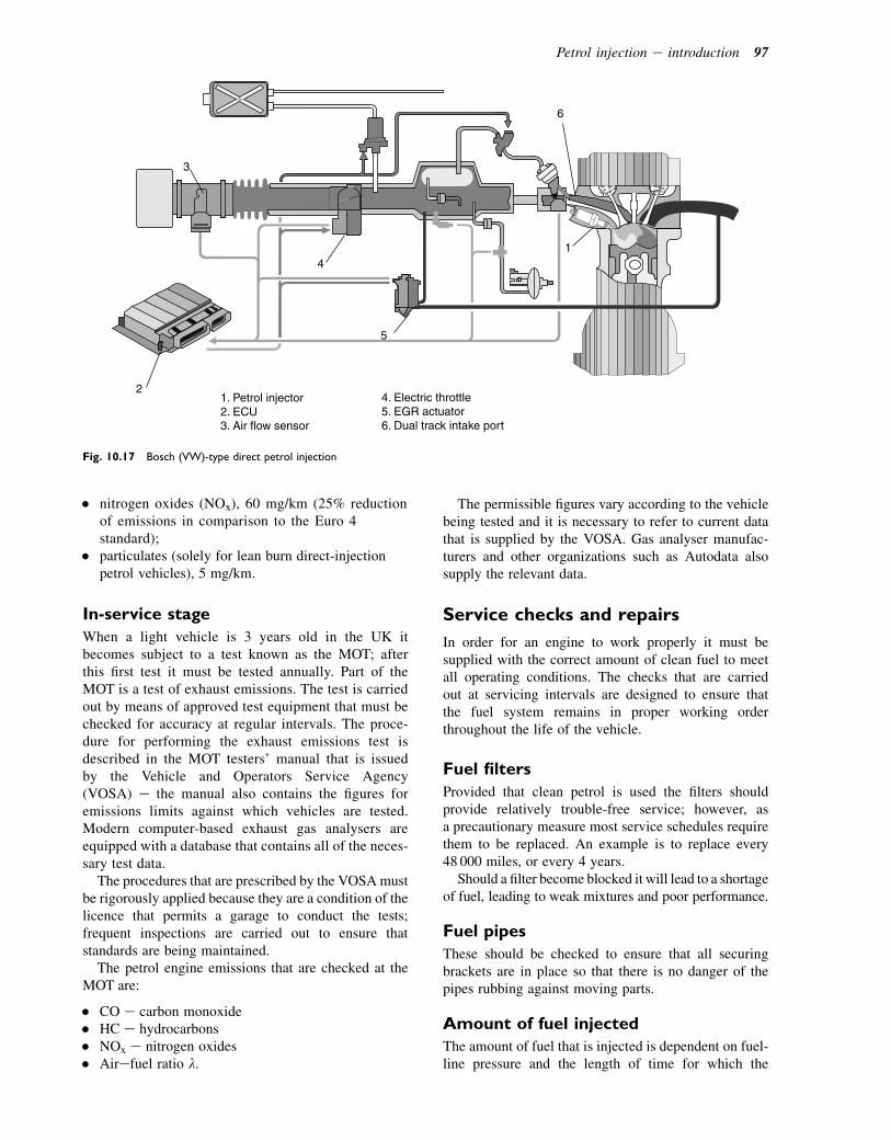
� nitrogen oxides (NOx), 60 mg/km (25% reductionof emissions in comparison to the Euro 4standard);
� particulates (solely for lean burn direct-injectionpetrol vehicles), 5 mg/km.
In-service stage
When a light vehicle is 3 years old in the UK itbecomes subject to a test known as the MOT; afterthis first test it must be tested annually. Part of theMOT is a test of exhaust emissions. The test is carriedout by means of approved test equipment that must bechecked for accuracy at regular intervals. The proce-dure for performing the exhaust emissions test isdescribed in the MOT testers’ manual that is issuedby the Vehicle and Operators Service Agency(VOSA) e the manual also contains the figures foremissions limits against which vehicles are tested.Modern computer-based exhaust gas analysers areequipped with a database that contains all of the neces-sary test data.
The procedures that are prescribed by the VOSAmustbe rigorously applied because they are a condition of thelicence that permits a garage to conduct the tests;frequent inspections are carried out to ensure thatstandards are being maintained.
The petrol engine emissions that are checked at theMOT are:
� CO e carbon monoxide� HC e hydrocarbons� NOx e nitrogen oxides� Airefuel ratio l.
The permissible figures vary according to the vehiclebeing tested and it is necessary to refer to current datathat is supplied by the VOSA. Gas analyser manufac-turers and other organizations such as Autodata alsosupply the relevant data.
Service checks and repairs
In order for an engine to work properly it must besupplied with the correct amount of clean fuel to meetall operating conditions. The checks that are carriedout at servicing intervals are designed to ensure thatthe fuel system remains in proper working orderthroughout the life of the vehicle.
Fuel filters
Provided that clean petrol is used the filters shouldprovide relatively trouble-free service; however, asa precautionary measure most service schedules requirethem to be replaced. An example is to replace every48 000 miles, or every 4 years.
Should a filter become blocked it will lead to a shortageof fuel, leading to weak mixtures and poor performance.
Fuel pipes
These should be checked to ensure that all securingbrackets are in place so that there is no danger of thepipes rubbing against moving parts.
Amount of fuel injected
The amount of fuel that is injected is dependent on fuel-line pressure and the length of time for which the
4
3
6
1
5
21. Petrol injector2. ECU3. Air flow sensor
4. Electric throttle5. EGR actuator6. Dual track intake port
Fig. 10.17 Bosch (VW)-type direct petrol injection
Petrol injection e introduction 97
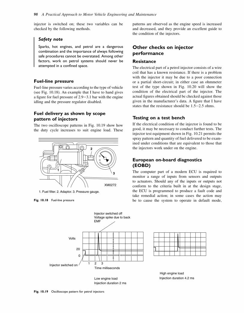
injector is switched on; these two variables can bechecked by the following methods.
Safety note
Sparks, hot engines, and petrol are a dangerouscombination and the importance of always followingsafe procedures cannot be overstated. Among otherfactors, work on petrol systems should never beattempted in a confined space.
Fuel-line pressure
Fuel-line pressure varies according to the type of vehicle(see Fig. 10.18). An example that I have to hand givesa figure for fuel pressure of 2.9e3.1 bar with the engineidling and the pressure regulator disabled.
Fuel delivery as shown by scopepattern of injectors
The two oscilloscope patterns in Fig. 10.19 show howthe duty cycle increases to suit engine load. These
patterns are observed as the engine speed is increasedand decreased, and they provide an excellent guide tothe condition of the injectors.
Other checks on injectorperformance
Resistance
The electrical part of a petrol injector consists of a wirecoil that has a known resistance. If there is a problemwith the injector it may be due to a poor connectionor a partial short-circuit; in either case an ohmmetertest of the type shown in Fig. 10.20 will show thecondition of the electrical part of the injector. Theactual figures obtained should be checked against thosegiven in the manufacturer’s data. A figure that I havestates that the resistance should be 1.5e2.5 ohms.
Testing on a test bench
If the electrical condition of the injector is found to begood, it may be necessary to conduct further tests. Theinjector test equipment shown in Fig. 10.21 permits thespray pattern and quantity of fuel delivered to be exam-ined under conditions that are equivalent to those thatthe injectors work under on the engine.
European on-board diagnostics(EOBD)
The computer part of a modern ECU is required tomonitor a range of inputs from sensors and outputsto actuators. Should any of the inputs or outputs notconform to the criteria built in at the design stage,the ECU is programmed to produce a fault code andtake remedial action; in some cases the action maybe to cause the system to operate in default mode,
2
3
XM0272
1. Fuel filter. 2. Adaptor. 3. Pressure gauge.
1
Fig. 10.18 Fuel-line pressure
Volts
20
0
1
Time milliseconds
Injector switched offVoltage spike due to backEMF
Injector switched on
Low engine load
High engine load
Injection duration 2 ms
Injection duration 4.2 ms
2 3
Fig. 10.19 Oscilloscope pattern for petrol injectors
98 A Practical Approach to Motor Vehicle Engineering and Maintenance

while in other cases it may be to alert the driver bydisplaying a warning at the engine fault lamp. Thefault codes that are produced are a useful aid indealing with faults in engine fuelling and exhaustemission problems.
Exhaust oxygen sensor faults
EOBD systems incorporate a second oxygen sensordownstream from the first. The second sensor samples athalf the frequency of the first one and the ECU comparesthe two results; if the second sensor detects a differentoxygen content from the first it is taken to mean that thecatalytic convertor is not functioning correctly.
Exhaust emissions
The exhaust gases are the products of combustion. Underideal circumstances, the exhaust products would becarbon dioxide, steam (water), and nitrogen. However,owing to the large range of operating conditions thatengines experience, exhaust gas contains several othergases and materials such as those in the following list:
� CO e due to rich mixture and incompletecombustion
� NOx e due to very high temperature� HC e due to poor combustion� Particulate matter (PM) e soot and organometallic
materials� SO2 e arising from combustion of the small amount
of sulphur in diesel fuel.
OHMS
Ohmmeter
Test leads
Injector terminals
Injector
Fig. 10.20 Resistance check on injector
The ASNU Injector Test Bay Checking amount of fuelinjected during test cycle
Calibrated measuringflasks
Injectors under test
Injector spray pattern.Numbers 1 and 5 are correct.
Injectors for testing mounted on the testbay
Visually check
the fuel
distribution
and fuel
delivery
Visually check the injectors for
electrical operation fuel distribution
and fuel atomization
Figure 10.21 Injector test bench
Petrol injection e introduction 99
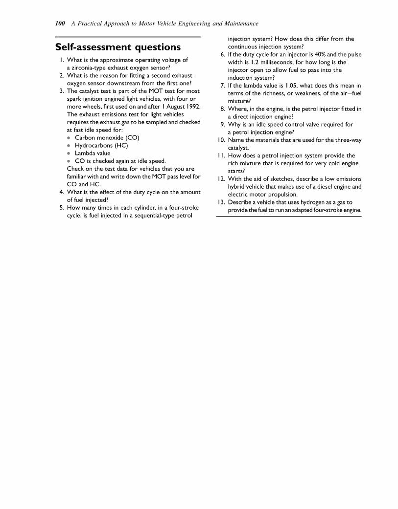
Self-assessment questions1. What is the approximate operating voltage of
a zirconia-type exhaust oxygen sensor?2. What is the reason for fitting a second exhaust
oxygen sensor downstream from the first one?3. The catalyst test is part of the MOT test for most
spark ignition engined light vehicles, with four ormore wheels, first used on and after 1 August 1992.The exhaust emissions test for light vehiclesrequires the exhaust gas to be sampled and checkedat fast idle speed for:� Carbon monoxide (CO)� Hydrocarbons (HC)� Lambda value� CO is checked again at idle speed.Check on the test data for vehicles that you arefamiliar with and write down the MOT pass level forCO and HC.
4. What is the effect of the duty cycle on the amountof fuel injected?
5. How many times in each cylinder, in a four-strokecycle, is fuel injected in a sequential-type petrol
injection system? How does this differ from thecontinuous injection system?
6. If the duty cycle for an injector is 40% and the pulsewidth is 1.2 milliseconds, for how long is theinjector open to allow fuel to pass into theinduction system?
7. If the lambda value is 1.05, what does this mean interms of the richness, or weakness, of the airefuelmixture?
8. Where, in the engine, is the petrol injector fitted ina direct injection engine?
9. Why is an idle speed control valve required fora petrol injection engine?
10. Name the materials that are used for the three-waycatalyst.
11. How does a petrol injection system provide therich mixture that is required for very cold enginestarts?
12. With the aid of sketches, describe a low emissionshybrid vehicle that makes use of a diesel engine andelectric motor propulsion.
13. Describe a vehicle that uses hydrogen as a gas toprovide the fuel to run an adapted four-stroke engine.
100 A Practical Approach to Motor Vehicle Engineering and Maintenance
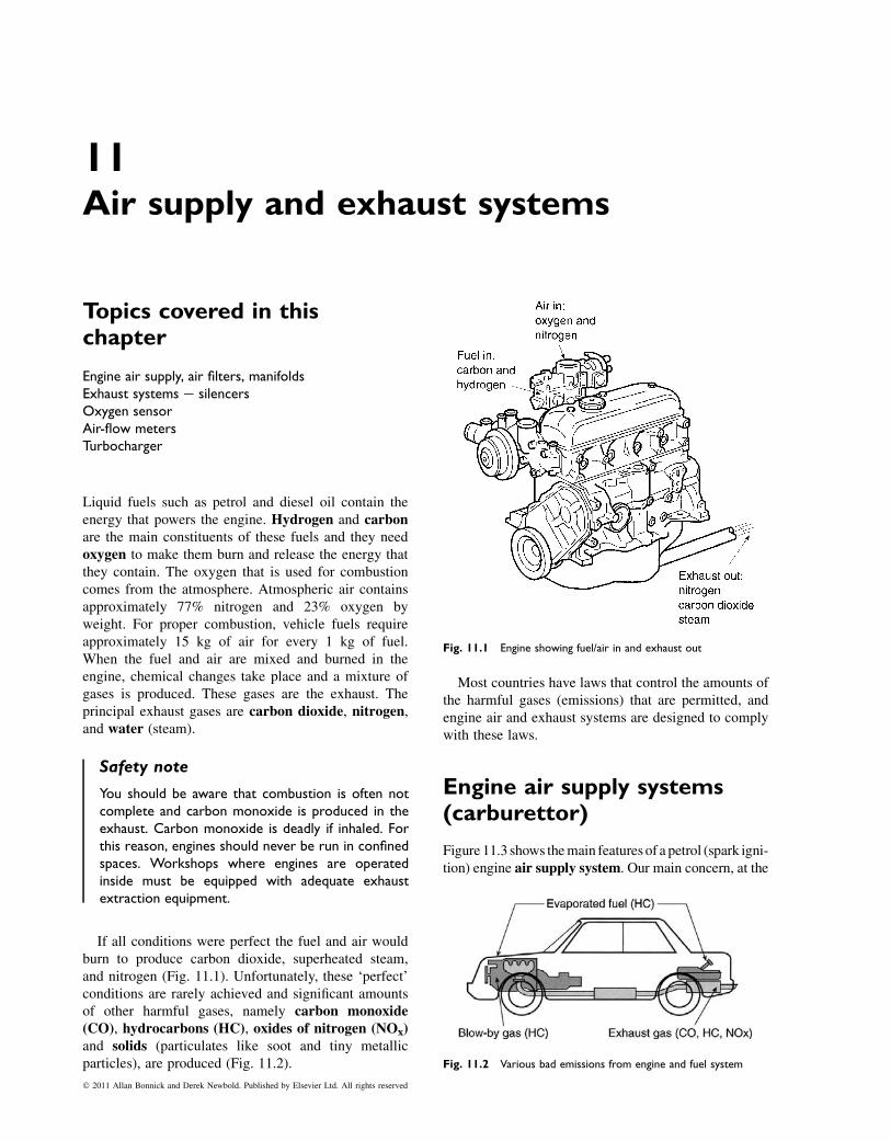
11Air supply and exhaust systems
Topics covered in thischapter
Engine air supply, air filters, manifoldsExhaust systems e silencersOxygen sensorAir-flow metersTurbocharger
Liquid fuels such as petrol and diesel oil contain theenergy that powers the engine. Hydrogen and carbonare the main constituents of these fuels and they needoxygen to make them burn and release the energy thatthey contain. The oxygen that is used for combustioncomes from the atmosphere. Atmospheric air containsapproximately 77% nitrogen and 23% oxygen byweight. For proper combustion, vehicle fuels requireapproximately 15 kg of air for every 1 kg of fuel.When the fuel and air are mixed and burned in theengine, chemical changes take place and a mixture ofgases is produced. These gases are the exhaust. Theprincipal exhaust gases are carbon dioxide, nitrogen,and water (steam).
Safety note
You should be aware that combustion is often notcomplete and carbon monoxide is produced in theexhaust. Carbon monoxide is deadly if inhaled. Forthis reason, engines should never be run in confinedspaces. Workshops where engines are operatedinside must be equipped with adequate exhaustextraction equipment.
If all conditions were perfect the fuel and air wouldburn to produce carbon dioxide, superheated steam,and nitrogen (Fig. 11.1). Unfortunately, these ‘perfect’conditions are rarely achieved and significant amountsof other harmful gases, namely carbon monoxide(CO), hydrocarbons (HC), oxides of nitrogen (NOx)and solids (particulates like soot and tiny metallicparticles), are produced (Fig. 11.2).
Most countries have laws that control the amounts ofthe harmful gases (emissions) that are permitted, andengine air and exhaust systems are designed to complywith these laws.
Engine air supply systems(carburettor)
Figure 11.3 shows themain features of a petrol (spark igni-tion) engine air supply system. Our main concern, at the
Fig. 11.1 Engine showing fuel/air in and exhaust out
Fig. 11.2 Various bad emissions from engine and fuel system
� 2011 Allan Bonnick and Derek Newbold. Published by Elsevier Ltd. All rights reserved
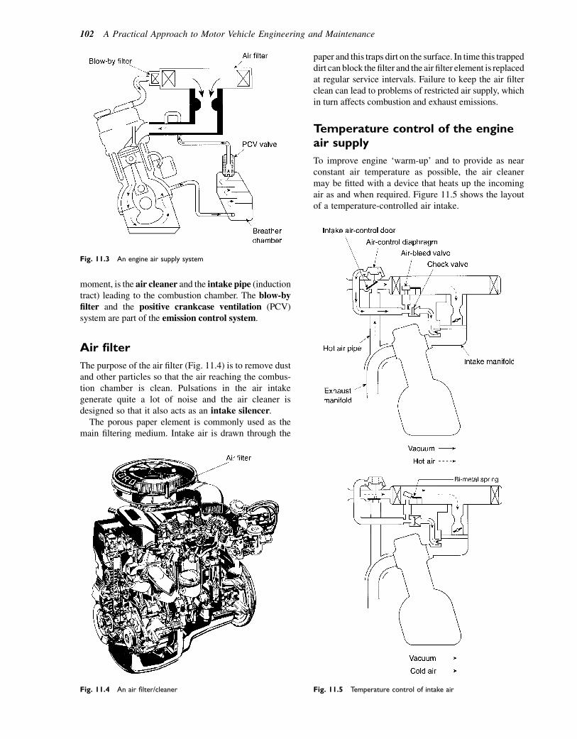
moment, is the air cleaner and the intake pipe (inductiontract) leading to the combustion chamber. The blow-byfilter and the positive crankcase ventilation (PCV)system are part of the emission control system.
Air filter
The purpose of the air filter (Fig. 11.4) is to remove dustand other particles so that the air reaching the combus-tion chamber is clean. Pulsations in the air intakegenerate quite a lot of noise and the air cleaner isdesigned so that it also acts as an intake silencer.
The porous paper element is commonly used as themain filtering medium. Intake air is drawn through the
paper and this traps dirt on the surface. In time this trappeddirt can block the filter and the air filter element is replacedat regular service intervals. Failure to keep the air filterclean can lead to problems of restricted air supply, whichin turn affects combustion and exhaust emissions.
Temperature control of the engineair supply
To improve engine ‘warm-up’ and to provide as nearconstant air temperature as possible, the air cleanermay be fitted with a device that heats up the incomingair as and when required. Figure 11.5 shows the layoutof a temperature-controlled air intake.
Fig. 11.3 An engine air supply system
Fig. 11.4 An air filter/cleaner Fig. 11.5 Temperature control of intake air
102 A Practical Approach to Motor Vehicle Engineering and Maintenance
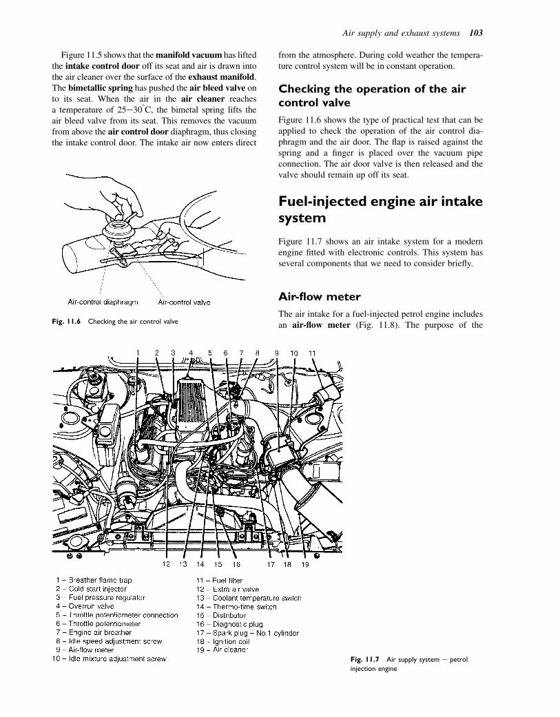
Figure 11.5 shows that themanifold vacuum has liftedthe intake control door off its seat and air is drawn intothe air cleaner over the surface of the exhaust manifold.The bimetallic spring has pushed the air bleed valve onto its seat. When the air in the air cleaner reachesa temperature of 25e308C, the bimetal spring lifts theair bleed valve from its seat. This removes the vacuumfrom above the air control door diaphragm, thus closingthe intake control door. The intake air now enters direct
from the atmosphere. During cold weather the tempera-ture control system will be in constant operation.
Checking the operation of the aircontrol valve
Figure 11.6 shows the type of practical test that can beapplied to check the operation of the air control dia-phragm and the air door. The flap is raised against thespring and a finger is placed over the vacuum pipeconnection. The air door valve is then released and thevalve should remain up off its seat.
Fuel-injected engine air intakesystem
Figure 11.7 shows an air intake system for a modernengine fitted with electronic controls. This system hasseveral components that we need to consider briefly.
Air-flow meter
The air intake for a fuel-injected petrol engine includesan air-flow meter (Fig. 11.8). The purpose of theFig. 11.6 Checking the air control valve
Fig. 11.7 Air supply system e petrol
injection engine
Air supply and exhaust systems 103
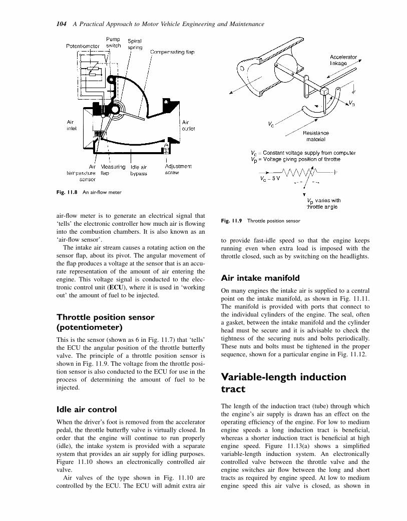
air-flow meter is to generate an electrical signal that‘tells’ the electronic controller how much air is flowinginto the combustion chambers. It is also known as an‘air-flow sensor’.
The intake air stream causes a rotating action on thesensor flap, about its pivot. The angular movement ofthe flap produces a voltage at the sensor that is an accu-rate representation of the amount of air entering theengine. This voltage signal is conducted to the elec-tronic control unit (ECU), where it is used in ‘workingout’ the amount of fuel to be injected.
Throttle position sensor(potentiometer)
This is the sensor (shown as 6 in Fig. 11.7) that ‘tells’the ECU the angular position of the throttle butterflyvalve. The principle of a throttle position sensor isshown in Fig. 11.9. The voltage from the throttle posi-tion sensor is also conducted to the ECU for use in theprocess of determining the amount of fuel to beinjected.
Idle air control
When the driver’s foot is removed from the acceleratorpedal, the throttle butterfly valve is virtually closed. Inorder that the engine will continue to run properly(idle), the intake system is provided with a separatesystem that provides an air supply for idling purposes.Figure 11.10 shows an electronically controlled airvalve.
Air valves of the type shown in Fig. 11.10 arecontrolled by the ECU. The ECU will admit extra air
to provide fast-idle speed so that the engine keepsrunning even when extra load is imposed with thethrottle closed, such as by switching on the headlights.
Air intake manifold
On many engines the intake air is supplied to a centralpoint on the intake manifold, as shown in Fig. 11.11.The manifold is provided with ports that connect tothe individual cylinders of the engine. The seal, oftena gasket, between the intake manifold and the cylinderhead must be secure and it is advisable to check thetightness of the securing nuts and bolts periodically.These nuts and bolts must be tightened in the propersequence, shown for a particular engine in Fig. 11.12.
Variable-length inductiontract
The length of the induction tract (tube) through whichthe engine’s air supply is drawn has an effect on theoperating efficiency of the engine. For low to mediumengine speeds a long induction tract is beneficial,whereas a shorter induction tract is beneficial at highengine speed. Figure 11.13(a) shows a simplifiedvariable-length induction system. An electronicallycontrolled valve between the throttle valve and theengine switches air flow between the long and shorttracts as required by engine speed. At low to mediumengine speed this air valve is closed, as shown in
Fig. 11.8 An air-flow meter
Fig. 11.9 Throttle position sensor
104 A Practical Approach to Motor Vehicle Engineering and Maintenance

Fig. 11.13(b). As the engine speed rises the electroniccontrol unit causes the air valve to open, as shown inFig. 11.13(c), and the main mass of air enters the engineby the short route.
Turbocharging
Engines that rely on atmospheric air pressure for theiroperation are known as naturally aspirated engines.The power output of naturally aspirated engines islimited by the amount of air that can be induced intothe cylinder on each induction stroke. Engine powercan be increased by forcing air into the cylinders underpressure. The turbocharger is commonly used onmodern engines to boost the pressure of the incomingair. The turbocharger consists of two main units, theturbine and the compressor, mounted on a commonshaft. The turbine is driven by exhaust gas and utilizesenergy that would otherwise be wasted by beingexpelled through the exhaust system into theatmosphere.
The general principle of turbocharging is shown inFig. 11.14. Exhaust gas energy is directed to the smallturbine, which is connected to the shaft that also drivesthe compressor. After driving the turbine, the exhaustgas travels through the exhaust system and out throughthe tail pipe. Intake air is drawn into the compressorthrough the air filter. The compressor raises the pres-sure to approximately 0.5 bar above atmospheric
Fig. 11.10 An air control valve
Fig. 11.11 An air intake manifold
Fig. 11.12 Tightening sequence for exhaust manifold retaining
hardware (nuts)
Air supply and exhaust systems 105
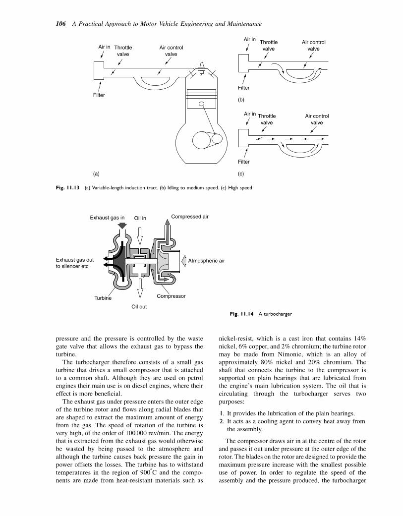
pressure and the pressure is controlled by the wastegate valve that allows the exhaust gas to bypass theturbine.
The turbocharger therefore consists of a small gasturbine that drives a small compressor that is attachedto a common shaft. Although they are used on petrolengines their main use is on diesel engines, where theireffect is more beneficial.
The exhaust gas under pressure enters the outer edgeof the turbine rotor and flows along radial blades thatare shaped to extract the maximum amount of energyfrom the gas. The speed of rotation of the turbine isvery high, of the order of 100 000 rev/min. The energythat is extracted from the exhaust gas would otherwisebe wasted by being passed to the atmosphere andalthough the turbine causes back pressure the gain inpower offsets the losses. The turbine has to withstandtemperatures in the region of 9008C and the compo-nents are made from heat-resistant materials such as
nickel-resist, which is a cast iron that contains 14%nickel, 6% copper, and 2% chromium; the turbine rotormay be made from Nimonic, which is an alloy ofapproximately 80% nickel and 20% chromium. Theshaft that connects the turbine to the compressor issupported on plain bearings that are lubricated fromthe engine’s main lubrication system. The oil that iscirculating through the turbocharger serves twopurposes:
1. It provides the lubrication of the plain bearings.2. It acts as a cooling agent to convey heat away from
the assembly.
The compressor draws air in at the centre of the rotorand passes it out under pressure at the outer edge of therotor. The blades on the rotor are designed to provide themaximum pressure increase with the smallest possibleuse of power. In order to regulate the speed of theassembly and the pressure produced, the turbocharger
(c)
(b)
(a)
Filter
Air in Air control valve
Throttle valve
Air in
Filter
Throttle valve
Air controlvalve
Air in
Filter
Throttle valve
Air control valve
Fig. 11.13 (a) Variable-length induction tract. (b) Idling to medium speed. (c) High speed
Exhaust gas outto silencer etc
Exhaust gas in Oil in Compressed air
Atmospheric air
Compressor
Oil out
Turbine
Fig. 11.14 A turbocharger
106 A Practical Approach to Motor Vehicle Engineering and Maintenance
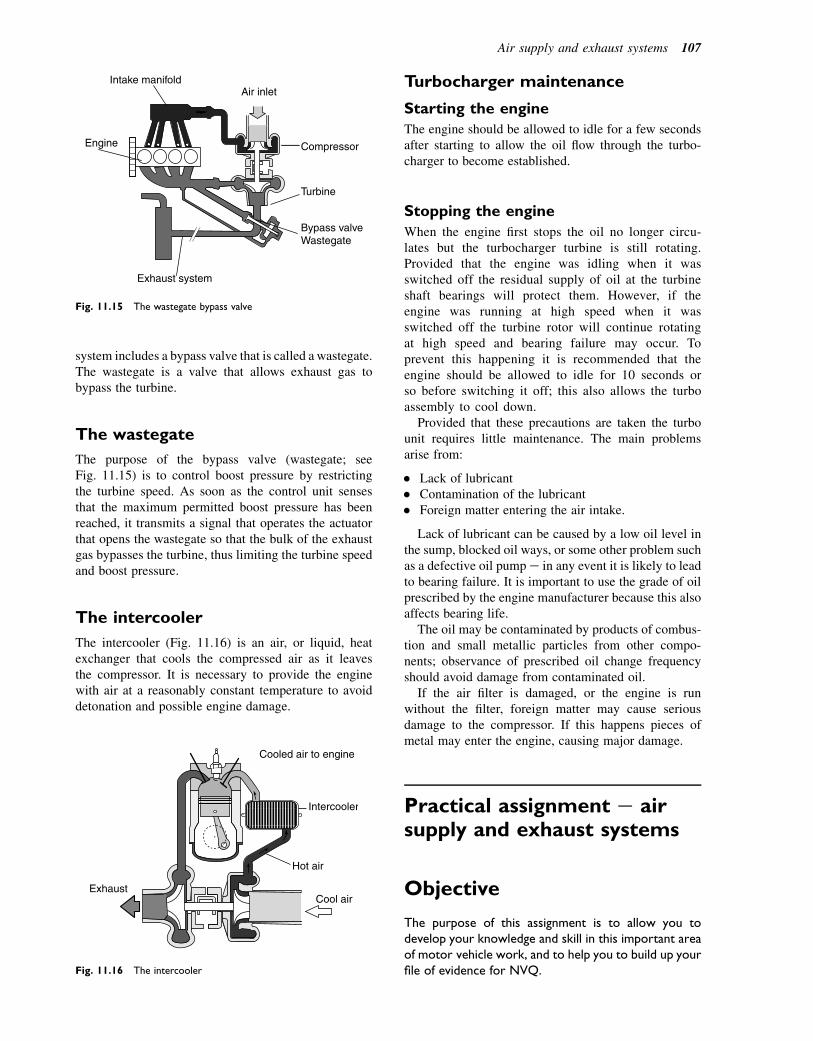
system includes a bypass valve that is called a wastegate.The wastegate is a valve that allows exhaust gas tobypass the turbine.
The wastegate
The purpose of the bypass valve (wastegate; seeFig. 11.15) is to control boost pressure by restrictingthe turbine speed. As soon as the control unit sensesthat the maximum permitted boost pressure has beenreached, it transmits a signal that operates the actuatorthat opens the wastegate so that the bulk of the exhaustgas bypasses the turbine, thus limiting the turbine speedand boost pressure.
The intercooler
The intercooler (Fig. 11.16) is an air, or liquid, heatexchanger that cools the compressed air as it leavesthe compressor. It is necessary to provide the enginewith air at a reasonably constant temperature to avoiddetonation and possible engine damage.
Turbocharger maintenance
Starting the engine
The engine should be allowed to idle for a few secondsafter starting to allow the oil flow through the turbo-charger to become established.
Stopping the engine
When the engine first stops the oil no longer circu-lates but the turbocharger turbine is still rotating.Provided that the engine was idling when it wasswitched off the residual supply of oil at the turbineshaft bearings will protect them. However, if theengine was running at high speed when it wasswitched off the turbine rotor will continue rotatingat high speed and bearing failure may occur. Toprevent this happening it is recommended that theengine should be allowed to idle for 10 seconds orso before switching it off; this also allows the turboassembly to cool down.
Provided that these precautions are taken the turbounit requires little maintenance. The main problemsarise from:
� Lack of lubricant� Contamination of the lubricant� Foreign matter entering the air intake.
Lack of lubricant can be caused by a low oil level inthe sump, blocked oil ways, or some other problem suchas a defective oil pump e in any event it is likely to leadto bearing failure. It is important to use the grade of oilprescribed by the engine manufacturer because this alsoaffects bearing life.
The oil may be contaminated by products of combus-tion and small metallic particles from other compo-nents; observance of prescribed oil change frequencyshould avoid damage from contaminated oil.
If the air filter is damaged, or the engine is runwithout the filter, foreign matter may cause seriousdamage to the compressor. If this happens pieces ofmetal may enter the engine, causing major damage.
Practical assignment e airsupply and exhaust systems
Objective
The purpose of this assignment is to allow you todevelop your knowledge and skill in this important areaof motor vehicle work, and to help you to build up yourfile of evidence for NVQ.
Engine
Exhaust system
Bypass valveWastegate
Turbine
Compressor
Air inletIntake manifold
Fig. 11.15 The wastegate bypass valve
Exhaust
Hot air
Intercooler
Cooled air to engine
Cool air
Fig. 11.16 The intercooler
Air supply and exhaust systems 107

Activity
The nature of this assignment is such that you will needto work under supervision, unless you have previouslybeen trained and are proficient. The assignment isintended to be undertaken during a routine service andMOT test on a petrol-engined vehicle that is equippedwith electronically controlled petrol injection. Theassignment is in two parts.
Part 1
1. Locate the idle control valve. Describe the purposeof this valve and describe any adjustments that can bemade to it.
2. Specify the effects on engine performance andexhaust emissions that may arise if this valve is notworking correctly.
Part 2
1. Perform the emissions test part of the MOT test.2. Record the results and compare them with the legal
limits.3. Write short notes on the test procedure and
describe any work that should be carried out beforestarting the emissions test.
4. Give details of remedial work that can be performedif a vehicle should fail the emissions test.
5. Make a list of the tools and equipment used.
Self-assessment questions1. A blocked air filter may cause:
(a) low fuel consumption(b) the engine to run rich(c) increased cooling system pressure(d) excess oxygen in the exhaust.
2. An air leak through the intake manifold flangegasket may cause:(a) the engine to run rich(b) the malfunction indicator lamp to illuminate(c) the positive crankcase ventilation system to fail(d) excess NOx in the exhaust.
3. Turbocharged engines:(a) are less efficient than naturally aspirated ones
because power is absorbed in driving theturbocharger
(b) are more efficient than naturally aspiratedengines because they make use of energy in theexhaust gas that would otherwise be wasted
(c) are normally diesel engines(d) have high fuel consumption.
4. An air-flow sensor:(a) provides an electrical signal that tells the ECU
how much air is flowing to the engine(b) controls the air flow to the air-conditioning
system(c) allows the exhaust gases to bypass the
turbocharger(d) restricts air flow to prevent engine overload.
5. The potentiometer-type throttle position sensor:(a) generates electricity that is used as a signal to
inform the ECU of the amount of throttleopening
(b) receives a supply of electricity and sends a signalto the ECU that is an accurate representation ofthrottle position
(c) is always situated on the accelerator pedal(d) always operates on the variable capacitance
principle.6. Exhaust gas oxygen sensors:
(a) are used to detect oxygen levels in theexhaust gas
(b) operate effectively at all temperatures(c) always generate electricity(d) are only needed on direct injection engines.
7. During combustion, hydrogen in the fuel combineswith oxygen from the air:(a) and produces water in the exhaust system(b) and produces NOx in the exhaust gas(c) and produces carbon monoxide in the
exhaust gas(d) and causes the ignition to be retarded.
8. When an engine fails the emissions test it meansthat:(a) the catalytic converter is not working(b) the emissions control system is not working and
this may be caused by a range of engineproblems
(c) the oxygen sensor has failed(d) the air filter is blocked.
9. Exhaust systems may be protected againstcorrosion by:(a) coating them inside and outside with a layer of
bitumen(b) a thin layer of aluminium applied to the inner
and outer surfaces(c) reducing the temperature of the exhaust gases(d) coating them with underseal.
10. Atmospheric air contains approximately 77%nitrogen and 23% oxygen by mass:(a) the nitrogen is a hindrance because it is not used
in combustion(b) the nitrogen helps to form water(c) the nitrogen forms part of the gas that expands
in the cylinder to make the engine work(d) the oxygen and nitrogen form NOx at very low
temperatures.
108 A Practical Approach to Motor Vehicle Engineering and Maintenance
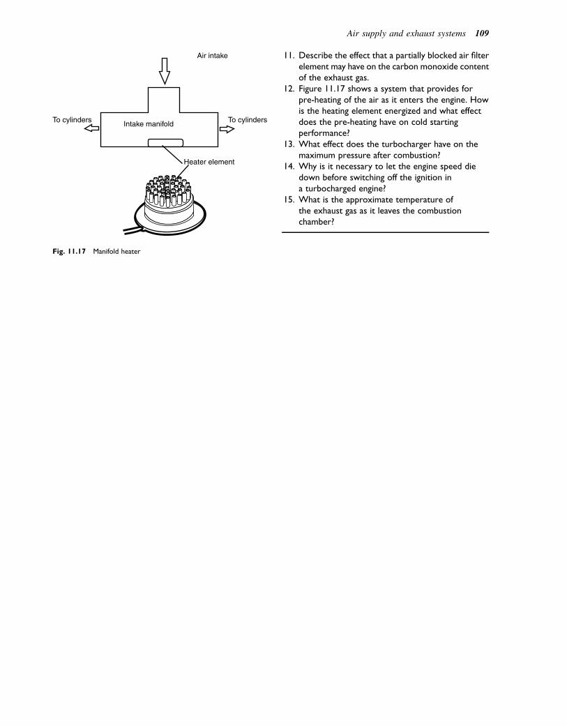
11. Describe the effect that a partially blocked air filterelement may have on the carbon monoxide contentof the exhaust gas.
12. Figure 11.17 shows a system that provides forpre-heating of the air as it enters the engine. Howis the heating element energized and what effectdoes the pre-heating have on cold startingperformance?
13. What effect does the turbocharger have on themaximum pressure after combustion?
14. Why is it necessary to let the engine speed diedown before switching off the ignition ina turbocharged engine?
15. What is the approximate temperature ofthe exhaust gas as it leaves the combustionchamber?
Heater element
Intake manifold
Air intake
To cylinders To cylinders
Fig. 11.17 Manifold heater
Air supply and exhaust systems 109
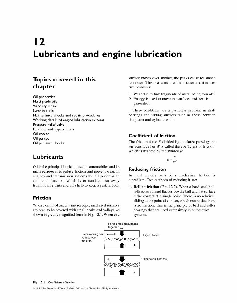
12Lubricants and engine lubrication
Topics covered in thischapter
Oil propertiesMulti-grade oilsViscosity indexSynthetic oilsMaintenance checks and repair proceduresWorking details of engine lubrication systemsPressure-relief valveFull-flow and bypass filtersOil coolerOil pumpsOil pressure checks
Lubricants
Oil is the principal lubricant used in automobiles and itsmain purpose is to reduce friction and prevent wear. Inengines and transmission systems the oil performs anadditional function, which is to conduct heat awayfrom moving parts and thus help to keep a system cool.
Friction
When examined under a microscope, machined surfacesare seen to be covered with small peaks and valleys, asshown in greatly magnified form in Fig. 12.1. When one
surface moves over another, the peaks cause resistanceto motion. This resistance is called friction and it causestwo problems:
1. Wear due to tiny fragments of metal being torn off.2. Energy is used to move the surfaces and heat is
generated.
These conditions are a particular problem in shaftbearings and sliding surfaces such as those betweenthe piston and cylinder wall.
Coefficient of friction
The friction force F divided by the force pressing thesurfaces together W is called the coefficient of friction,which is denoted by the symbol m:
m5F
W:
Reducing friction
In most moving parts of a mechanism friction isa problem. Two methods of reducing it are:
1. Rolling friction (Fig. 12.2). When a hard steel ballrolls across a hard flat surface the ball and flat surfacemake contact at a single point. There is no relativesliding at the point of contact, which means that thereis no friction. This is the principle of ball and rollerbearings that are used extensively in automotivesystems.
Dry surfacesForce moving onesurface over the other
Oil between surfaces
Force pressing surfaces together w
F
Fig. 12.1 Coefficient of friction
� 2011 Allan Bonnick and Derek Newbold. Published by Elsevier Ltd. All rights reserved
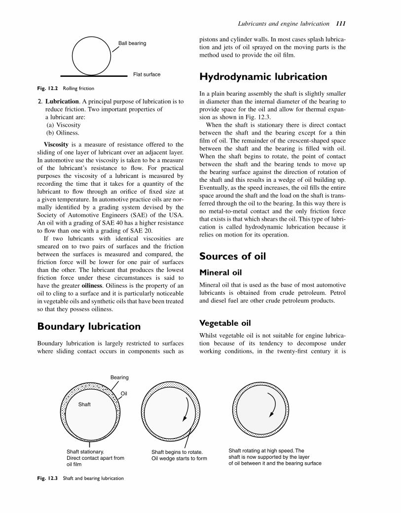
2. Lubrication. A principal purpose of lubrication is toreduce friction. Two important properties ofa lubricant are:(a) Viscosity(b) Oiliness.
Viscosity is a measure of resistance offered to thesliding of one layer of lubricant over an adjacent layer.In automotive use the viscosity is taken to be a measureof the lubricant’s resistance to flow. For practicalpurposes the viscosity of a lubricant is measured byrecording the time that it takes for a quantity of thelubricant to flow through an orifice of fixed size ata given temperature. In automotive practice oils are nor-mally identified by a grading system devised by theSociety of Automotive Engineers (SAE) of the USA.An oil with a grading of SAE 40 has a higher resistanceto flow than one with a grading of SAE 20.
If two lubricants with identical viscosities aresmeared on to two pairs of surfaces and the frictionbetween the surfaces is measured and compared, thefriction force will be lower for one pair of surfacesthan the other. The lubricant that produces the lowestfriction force under these circumstances is said tohave the greater oiliness. Oiliness is the property of anoil to cling to a surface and it is particularly noticeablein vegetable oils and synthetic oils that have been treatedso that they possess oiliness.
Boundary lubrication
Boundary lubrication is largely restricted to surfaceswhere sliding contact occurs in components such as
pistons and cylinder walls. In most cases splash lubrica-tion and jets of oil sprayed on the moving parts is themethod used to provide the oil film.
Hydrodynamic lubrication
In a plain bearing assembly the shaft is slightly smallerin diameter than the internal diameter of the bearing toprovide space for the oil and allow for thermal expan-sion as shown in Fig. 12.3.
When the shaft is stationary there is direct contactbetween the shaft and the bearing except for a thinfilm of oil. The remainder of the crescent-shaped spacebetween the shaft and the bearing is filled with oil.When the shaft begins to rotate, the point of contactbetween the shaft and the bearing tends to move upthe bearing surface against the direction of rotation ofthe shaft and this results in a wedge of oil building up.Eventually, as the speed increases, the oil fills the entirespace around the shaft and the load on the shaft is trans-ferred through the oil to the bearing. In this way there isno metal-to-metal contact and the only friction forcethat exists is that which shears the oil. This type of lubri-cation is called hydrodynamic lubrication because itrelies on motion for its operation.
Sources of oil
Mineral oil
Mineral oil that is used as the base of most automotivelubricants is obtained from crude petroleum. Petroland diesel fuel are other crude petroleum products.
Vegetable oil
Whilst vegetable oil is not suitable for engine lubrica-tion because of its tendency to decompose underworking conditions, in the twenty-first century it is
Bearing
Oil
Shaft
Shaft stationary.Direct contact apart fromoil film
Shaft begins to rotate.Oil wedge starts to form
Shaft rotating at high speed. Theshaft is now supported by the layerof oil between it and the bearing surface
Fig. 12.3 Shaft and bearing lubrication
Ball bearing
Flat surface
Fig. 12.2 Rolling friction
Lubricants and engine lubrication 111
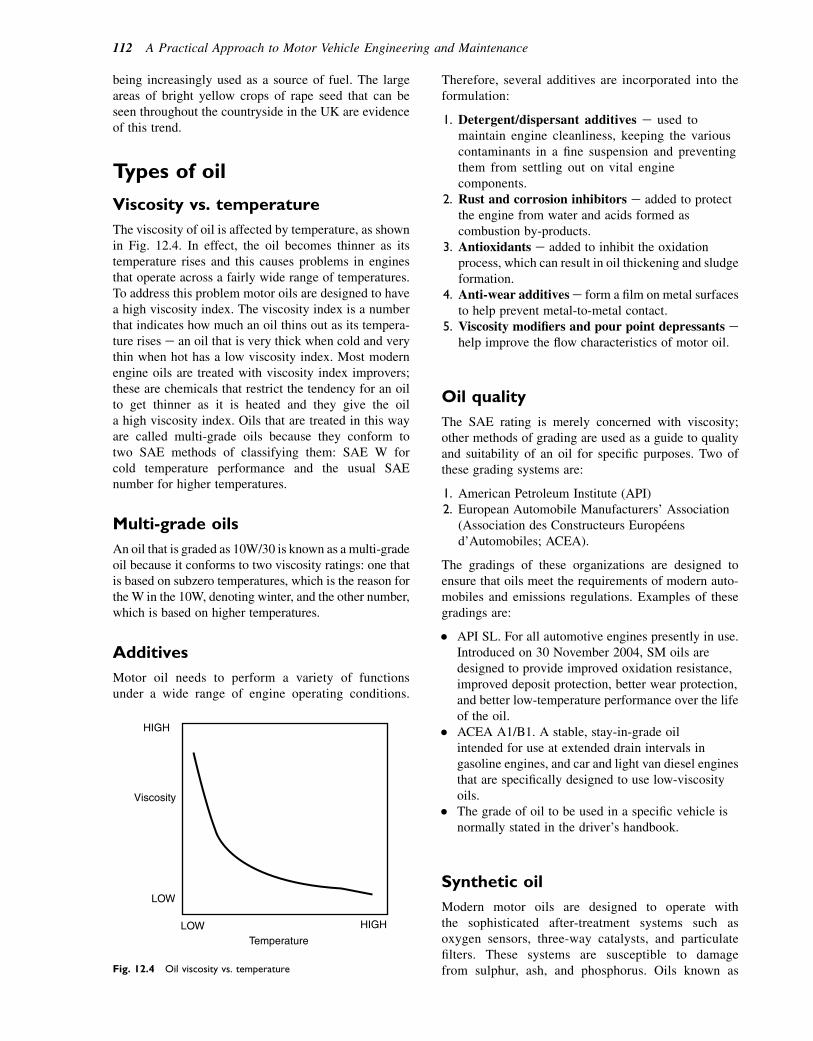
being increasingly used as a source of fuel. The largeareas of bright yellow crops of rape seed that can beseen throughout the countryside in the UK are evidenceof this trend.
Types of oil
Viscosity vs. temperature
The viscosity of oil is affected by temperature, as shownin Fig. 12.4. In effect, the oil becomes thinner as itstemperature rises and this causes problems in enginesthat operate across a fairly wide range of temperatures.To address this problem motor oils are designed to havea high viscosity index. The viscosity index is a numberthat indicates how much an oil thins out as its tempera-ture rises e an oil that is very thick when cold and verythin when hot has a low viscosity index. Most modernengine oils are treated with viscosity index improvers;these are chemicals that restrict the tendency for an oilto get thinner as it is heated and they give the oila high viscosity index. Oils that are treated in this wayare called multi-grade oils because they conform totwo SAE methods of classifying them: SAE W forcold temperature performance and the usual SAEnumber for higher temperatures.
Multi-grade oils
An oil that is graded as 10W/30 is known as a multi-gradeoil because it conforms to two viscosity ratings: one thatis based on subzero temperatures, which is the reason forthe W in the 10W, denoting winter, and the other number,which is based on higher temperatures.
Additives
Motor oil needs to perform a variety of functionsunder a wide range of engine operating conditions.
Therefore, several additives are incorporated into theformulation:
1. Detergent/dispersant additives e used tomaintain engine cleanliness, keeping the variouscontaminants in a fine suspension and preventingthem from settling out on vital enginecomponents.
2. Rust and corrosion inhibitors e added to protectthe engine from water and acids formed ascombustion by-products.
3. Antioxidants e added to inhibit the oxidationprocess, which can result in oil thickening and sludgeformation.
4. Anti-wear additivese form a film on metal surfacesto help prevent metal-to-metal contact.
5. Viscosity modifiers and pour point depressants ehelp improve the flow characteristics of motor oil.
Oil quality
The SAE rating is merely concerned with viscosity;other methods of grading are used as a guide to qualityand suitability of an oil for specific purposes. Two ofthese grading systems are:
1. American Petroleum Institute (API)2. European Automobile Manufacturers’ Association
(Association des Constructeurs Europeensd’Automobiles; ACEA).
The gradings of these organizations are designed toensure that oils meet the requirements of modern auto-mobiles and emissions regulations. Examples of thesegradings are:
� API SL. For all automotive engines presently in use.Introduced on 30 November 2004, SM oils aredesigned to provide improved oxidation resistance,improved deposit protection, better wear protection,and better low-temperature performance over the lifeof the oil.
� ACEA A1/B1. A stable, stay-in-grade oilintended for use at extended drain intervals ingasoline engines, and car and light van diesel enginesthat are specifically designed to use low-viscosityoils.
� The grade of oil to be used in a specific vehicle isnormally stated in the driver’s handbook.
Synthetic oil
Modern motor oils are designed to operate withthe sophisticated after-treatment systems such asoxygen sensors, three-way catalysts, and particulatefilters. These systems are susceptible to damagefrom sulphur, ash, and phosphorus. Oils known as
HIGH
HIGH
Temperature
Viscosity
LOW
LOW
Fig. 12.4 Oil viscosity vs. temperature
112 A Practical Approach to Motor Vehicle Engineering and Maintenance
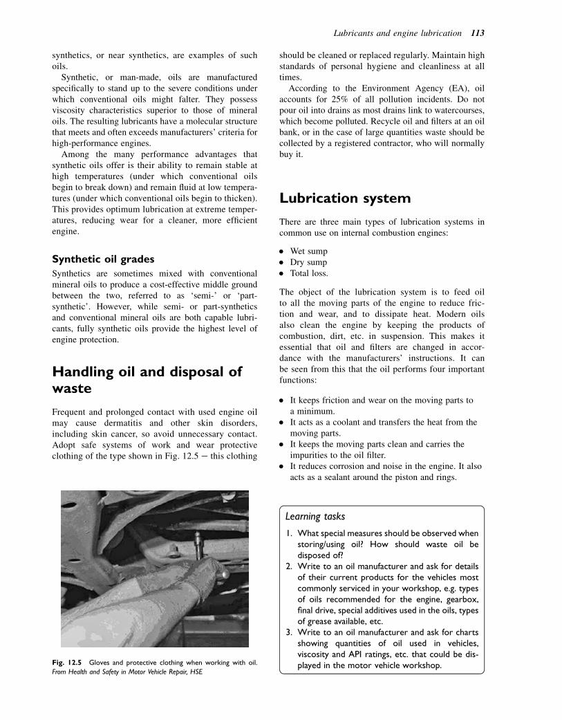
synthetics, or near synthetics, are examples of suchoils.
Synthetic, or man-made, oils are manufacturedspecifically to stand up to the severe conditions underwhich conventional oils might falter. They possessviscosity characteristics superior to those of mineraloils. The resulting lubricants have a molecular structurethat meets and often exceeds manufacturers’ criteria forhigh-performance engines.
Among the many performance advantages thatsynthetic oils offer is their ability to remain stable athigh temperatures (under which conventional oilsbegin to break down) and remain fluid at low tempera-tures (under which conventional oils begin to thicken).This provides optimum lubrication at extreme temper-atures, reducing wear for a cleaner, more efficientengine.
Synthetic oil grades
Synthetics are sometimes mixed with conventionalmineral oils to produce a cost-effective middle groundbetween the two, referred to as ‘semi-’ or ‘part-synthetic’. However, while semi- or part-syntheticsand conventional mineral oils are both capable lubri-cants, fully synthetic oils provide the highest level ofengine protection.
Handling oil and disposal ofwaste
Frequent and prolonged contact with used engine oilmay cause dermatitis and other skin disorders,including skin cancer, so avoid unnecessary contact.Adopt safe systems of work and wear protectiveclothing of the type shown in Fig. 12.5 e this clothing
should be cleaned or replaced regularly. Maintain highstandards of personal hygiene and cleanliness at alltimes.
According to the Environment Agency (EA), oilaccounts for 25% of all pollution incidents. Do notpour oil into drains as most drains link to watercourses,which become polluted. Recycle oil and filters at an oilbank, or in the case of large quantities waste should becollected by a registered contractor, who will normallybuy it.
Lubrication system
There are three main types of lubrication systems incommon use on internal combustion engines:
� Wet sump� Dry sump� Total loss.
The object of the lubrication system is to feed oilto all the moving parts of the engine to reduce fric-tion and wear, and to dissipate heat. Modern oilsalso clean the engine by keeping the products ofcombustion, dirt, etc. in suspension. This makes itessential that oil and filters are changed in accor-dance with the manufacturers’ instructions. It canbe seen from this that the oil performs four importantfunctions:
� It keeps friction and wear on the moving parts toa minimum.
� It acts as a coolant and transfers the heat from themoving parts.
� It keeps the moving parts clean and carries theimpurities to the oil filter.
� It reduces corrosion and noise in the engine. It alsoacts as a sealant around the piston and rings.
Learning tasks
1. What special measures should be observed whenstoring/using oil? How should waste oil bedisposed of?
2. Write to an oil manufacturer and ask for detailsof their current products for the vehicles mostcommonly serviced in your workshop, e.g. typesof oils recommended for the engine, gearbox,final drive, special additives used in the oils, typesof grease available, etc.
3. Write to an oil manufacturer and ask for chartsshowing quantities of oil used in vehicles,viscosity and API ratings, etc. that could be dis-played in the motor vehicle workshop.Fig. 12.5 Gloves and protective clothing when working with oil.
From Health and Safety in Motor Vehicle Repair, HSE
Lubricants and engine lubrication 113

Main components in the lubricationsystem
The lubrication system is mostly pressurized andconsists of the following main components:
� Oil pumpe draws the oil from the sump and deliversit under pressure to the engine lubrication system.
� Relief valve e limits the maximum pressure of theoil supplied by the pump to the system.
� Sump e serves as a reservoir for the oil.� Oil galleries e are channels or drillings through
which the oil passes to the different lubrication pointsin the engine.
� Oil pressure indicator e shows whether the oilpressure is being keptwithin themanufacturers’ limits.
� Oil filter e filters the oil, removing impurities tokeep it clean.
A typical lubrication system works in the followingway:
1. Oil is drawn from the sump by the oil pump.2. The pump pressurizes the oil and passes it through
the oil filter into the oil galleries and passages thatlead to the crankshaft and camshaft bearings and, insome engines, the rocker shaft and rocker arms.
3. The oil splashed from the crankshaft lubricates thepistons and other internal parts of the engine.
4. After lubricating the moving components, the oildrips back down into the sump. Figure 12.6 shows theoil flow in an engine lubrication system.
Function of the oil
When looking at the working surfaces of, say, the crank-shaft (A in Fig. 12.7) and the main bearings in which itruns (B), they appear to be blank and smooth. But whenobserved under a powerful microscope they will be seento be uneven and rough. When oil is introduced betweenthese surfaces, it fills up the slight irregularities andforms a thin layer, called an oil film. It is this oil filmthat separates the surfaces and, when the componentsare rotating, prevents metal-to-metal contact. Whenthe engine is operating the oil must be strong enoughto withstand the heavy loads imposed on all the movingparts. The oil is therefore delivered under pressure to thebearings and, to enable it to enter, a very small clearancebetween the shaft and bearing is necessary.
The clearance must be sufficient for the oil to enter,but small enough to resist the heavy loadings to whichthe bearings are subjected. This clearance is approxi-mately 0.05 mm for a shaft of 60e70 mm diameter.When the shaft is not rotating but is resting on the bear-ings, only a very thin film of residual oil separates thesurfaces. As the engine starts the only lubrication forthe first revolution is provided by this thin film of oil;as the revolutions increase, the oil pump starts to deliverthe oil under pressure to the bearings. The oil is drawnround by the rotating shaft which, together with thepressure, forms an oil wedge that lifts the shaft upfrom the bearing. The shaft then rotates freely, separatedfrom the bearings by this thin film of oil. A correctbearing clearance is shown in Fig. 12.8.
Fig. 12.6 Lubrication circuit for an overhead
camshaft (OHC) engine
114 A Practical Approach to Motor Vehicle Engineering and Maintenance

It is important that the bearings have the correct clear-ance. Too much will cause the oil to escape from thebearing without being able to create the required oilwedge; too little will restrict the oil from entering thebearing, causing metal-to-metal contact. In both caseswear will increase.
The oil that is pressed out from the bearings issplashed around and forms an oil mist, which lubricatesthe cylinder and piston (Fig. 12.9). In some cases a holeis drilled from the side of the connecting rod into thebearing shell to spray oil on to the thrust side of thecylinder wall.
Function of the sump
When the engine is filled with oil, it flows down throughthe engine into a container called the sump. This isattached to the bottom of the engine block with a seriesof small bolts, usually with a gasket between the blockand the sump. It is commonly formed from sheet steel
pressed to a shape that has one end slightly lower toform the oil reservoir. In the bottom of the sump is thedrain plug. Baffle plates are fitted to prevent the oilfrom splashing around or surging when the vehicle isaccelerating and braking or going round corners. If allthe oil is allowed to move to the rear or to the side ofthe sump, the oil pick-up may become exposed, causingair to be drawn into the lubrication. The sump also actsas an oil cooler because it extends into the air streamunder the vehicle. To assist with the cooling processthere may also be small fins formed on the outside toincrease its surface area. Aluminium is sometimesused to give a more rigid structure to support the crank-shaft and crankcase of the engine. Two types of sumpare shown in Fig. 12.10.
Oil level indicators
The level in the sump is checked by means of a dipstickon which the maximum and minimum oil levels areindicated. A number of vehicles fit indicators to showthe driver the level of oil in the engine without havingto lift the bonnet and remove the dipstick manually.
Fig. 12.7 Bearing surface shown under a microscope. Oil under
pressure keeps the surfaces apart
Fig. 12.8 Bearing clearance correct
Lubricants and engine lubrication 115
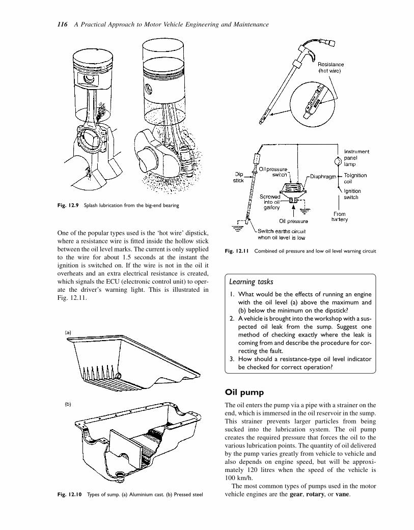
One of the popular types used is the ‘hot wire’ dipstick,where a resistance wire is fitted inside the hollow stickbetween the oil level marks. The current is only suppliedto the wire for about 1.5 seconds at the instant theignition is switched on. If the wire is not in the oil itoverheats and an extra electrical resistance is created,which signals the ECU (electronic control unit) to oper-ate the driver’s warning light. This is illustrated inFig. 12.11.
Learning tasks
1. What would be the effects of running an enginewith the oil level (a) above the maximum and(b) below the minimum on the dipstick?
2. A vehicle is brought into the workshop with a sus-pected oil leak from the sump. Suggest onemethod of checking exactly where the leak iscoming from and describe the procedure for cor-recting the fault.
3. How should a resistance-type oil level indicatorbe checked for correct operation?
Oil pump
The oil enters the pump via a pipe with a strainer on theend, which is immersed in the oil reservoir in the sump.This strainer prevents larger particles from beingsucked into the lubrication system. The oil pumpcreates the required pressure that forces the oil to thevarious lubrication points. The quantity of oil deliveredby the pump varies greatly from vehicle to vehicle andalso depends on engine speed, but will be approxi-mately 120 litres when the speed of the vehicle is100 km/h.
The most common types of pumps used in the motorvehicle engines are the gear, rotary, or vane.
Fig. 12.9 Splash lubrication from the big-end bearing
Fig. 12.10 Types of sump. (a) Aluminium cast. (b) Pressed steel
Fig. 12.11 Combined oil pressure and low oil level warning circuit
116 A Practical Approach to Motor Vehicle Engineering and Maintenance
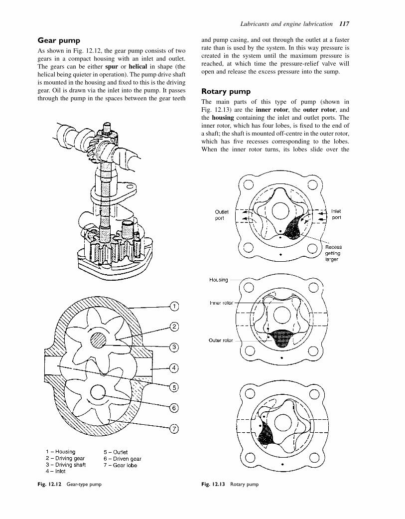
Gear pump
As shown in Fig. 12.12, the gear pump consists of twogears in a compact housing with an inlet and outlet.The gears can be either spur or helical in shape (thehelical being quieter in operation). The pump drive shaftis mounted in the housing and fixed to this is the drivinggear. Oil is drawn via the inlet into the pump. It passesthrough the pump in the spaces between the gear teeth
and pump casing, and out through the outlet at a fasterrate than is used by the system. In this way pressure iscreated in the system until the maximum pressure isreached, at which time the pressure-relief valve willopen and release the excess pressure into the sump.
Rotary pump
The main parts of this type of pump (shown inFig. 12.13) are the inner rotor, the outer rotor, andthe housing containing the inlet and outlet ports. Theinner rotor, which has four lobes, is fixed to the end ofa shaft; the shaft is mounted off-centre in the outer rotor,which has five recesses corresponding to the lobes.When the inner rotor turns, its lobes slide over the
Fig. 12.12 Gear-type pump Fig. 12.13 Rotary pump
Lubricants and engine lubrication 117
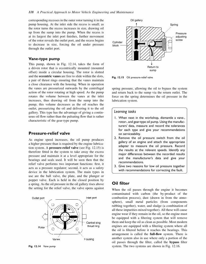
corresponding recesses in the outer rotor turning it in thepump housing. At the inlet side the recess is small; asthe rotor turns the recess increases in size, drawing oilup from the sump into the pump. When the recess isat its largest the inlet port finishes, further movementof the rotor reveals the outlet port, and the recess beginsto decrease in size, forcing the oil under pressurethrough the outlet port.
Vane-type pump
This pump, shown in Fig. 12.14, takes the form ofa driven rotor that is eccentrically mounted (mountedoffset) inside a circular housing. The rotor is slottedand the eccentric vanes are free to slide within the slots,a pair of thrust rings ensuring that the vanes maintaina close clearance with the housing. When in operationthe vanes are pressurized outwards by the centrifugalaction of the rotor rotating at high speed. As the pumprotates the volume between the vanes at the inletincreases, thus drawing oil from the sump into thepump; this volume decreases as the oil reaches theoutlet, pressurizing the oil and delivering it to the oilgallery. This type has the advantage of giving a contin-uous oil flow rather than the pulsating flow that is rathercharacteristic of the gear-type pump.
Pressure-relief valve
As engine speed increases, the oil pump producesa higher pressure than is required by the engine lubrica-tion system. A pressure-relief valve (see Fig. 12.15) istherefore fitted in the system to take away the excesspressure and maintain it at a level appropriate for thebearings and seals used. It will be seen then that therelief valve performs two important functions: first, itacts as a pressure regulator; second, it acts as a safetydevice in the lubrication system. The main types inuse are the ball valve, the plate, and the plunger orpoppet valve. Each is held in the closed position bya spring. As the oil pressure in the oil gallery rises abovethe setting for the relief valve, the valve opens against
spring pressure, allowing the oil to bypass the systemand return back to the sump via the return outlet. Theforce on the spring determines the oil pressure in thelubrication system.
Learning tasks
1. When next in the workshop, dismantle a vane-,rotor-, and gear-type oil pump. Using the manufac-turers’ data, measure and record the tolerancesfor each type and give your recommendationson serviceability.
2. Remove the oil pressure switch from the oilgallery of an engine and attach the appropriateadapter to measure the oil pressure. Recordthe results at the relevant speeds. Identify anymajor differences between the recorded resultsand the manufacturer’s data and give yourrecommendations.
3. Give two reasons for low oil pressure togetherwith recommendations for correcting the fault.
Oil filter
When the oil passes through the engine it becomescontaminated with carbon (the by-product of thecombustion process), dust (drawn in from the atmo-sphere), small metal particles (from componentsrubbing together), water, and sludge (a combination ofall these impurities mixed together). All these will causeengine wear if they remain in the oil, so the engine mustbe equipped with a filtering system that will removethem and keep the oil as clean as possible. Most modernengines are equipped with a filtering system where allthe oil is filtered before it reaches the bearings. Thisarrangement is called the full-flow system. There isanother system also in use where only a portion of theoil passes through the filter, called the bypass filtersystem. The two systems are shown in Fig. 12.16.Fig. 12.14 Vane pump
Cylinderblock
Spring
Oil gallery
Return tosump
Pressureadjustingscrew
Fig. 12.15 Oil pressure-relief valve
118 A Practical Approach to Motor Vehicle Engineering and Maintenance
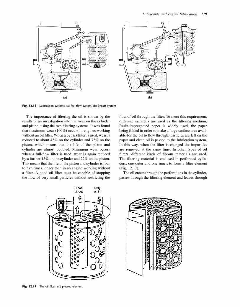
The importance of filtering the oil is shown by theresults of an investigation into the wear on the cylinderand piston, using the two filtering systems. It was foundthat maximum wear (100%) occurs in engines workingwithout an oil filter. When a bypass filter is used, wear isreduced to about 43% on the cylinder and 73% on thepiston, which means that the life of the piston andcylinder are almost doubled. Minimum wear occurswhen a full-flow filter is used; wear is again reducedby a further 15% on the cylinder and 22% on the piston.This means that the life of the piston and cylinder is fourto five times longer than in an engine working withouta filter. A good oil filter must be capable of stoppingthe flow of very small particles without restricting the
flow of oil through the filter. To meet this requirement,different materials are used as the filtering medium.Resin-impregnated paper is widely used, the paperbeing folded in order to make a large surface area avail-able for the oil to flow through; particles are left on thepaper and clean oil is passed to the lubrication system.In this way, when the filter is changed the impuritiesare removed at the same time. In other types of oilfilters, different kinds of fibrous materials are used.The filtering material is enclosed in perforated cylin-ders, one outer and one inner, to form a filter element(Fig. 12.17).
The oil enters through the perforations in the cylinder,passes through the filtering element and leaves through
(a) (b)
Fig. 12.16 Lubrication systems. (a) Full-flow system. (b) Bypass system
Fig. 12.17 The oil filter and pleated element
Lubricants and engine lubrication 119

the central tube outlet. Many modern filters are now thecartridge type, which is removed complete. The advan-tages of this disposable type are that it cleans the oilvery efficiently, it is relatively easy to change, and it isless messy to remove. The filter element can also belocated in a removable metal container. With thereplaceable-element type it is only the element itselfthat is changed, the container is thoroughly cleaned,and the ‘O’ ring replaced.
Full-flow filter
Oil filter operation is shown in Fig. 12.18. The mostwidely used filtering system is the full-flow filter. Theconstruction of the filter is very efficient because allthe oil is passed through the filter before it flows tothe bearings. After a certain length of time the elementbecomes dirty and less efficient, and must therefore bechanged. If the element is not changed regularly theimpurities will accumulate and the element will becomeclogged, restricting or preventing the oil from passingthrough the filter. For this reason a relief valve is fittedinto the filter, which opens and allows the oil to bypassthe clogged filter element and flow directly to the bear-ings unrestricted. If the condition is allowed to continue,unfiltered oil will carry abrasive particles to thebearings, causing rapid wear.
Cartridge filter
In the cartridge filter the relief valve is in the filter(shown in the open position in Fig. 12.19). Many ofthe filters now contain a valve underneath the inlethole, which opens when oil pressure forces oil into thefilter. When the engine stops and the oil flow ceases,the valve closes and the oil is kept within the filter.
This prevents it from draining back into the sump. Italso has the advantage of enabling the engine to developthe oil pressure more quickly when starting from cold.Correct operation is shown in Fig. 12.20.
Disc filter
This type of full-flow filter (shown in Fig. 12.21) is usedin large diesel engines. The oil is filtered by being forced
Fig. 12.18 Oil filter operation. (a) Oil being filtered. (b) Oil filter blocked
Fig. 12.19 Cartridge oil filter with oil relief valve open
120 A Practical Approach to Motor Vehicle Engineering and Maintenance
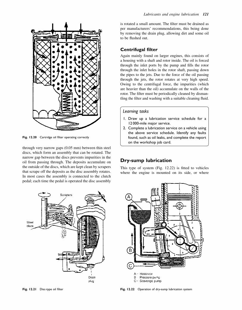
through very narrow gaps (0.05 mm) between thin steeldiscs, which form an assembly that can be rotated. Thenarrow gap between the discs prevents impurities in theoil from passing through. The deposits accumulate onthe outside of the discs, which are kept clean by scrapersthat scrape off the deposits as the disc assembly rotates.In most cases the assembly is connected to the clutchpedal; each time the pedal is operated the disc assembly
is rotated a small amount. The filter must be drained asper manufacturers’ recommendations, this being doneby removing the drain plug, allowing dirt and some oilto be flushed out.
Centrifugal filter
Again mainly found on larger engines, this consists ofa housing with a shaft and rotor inside. The oil is forcedthrough the inlet ports by the pump and fills the rotorthrough the inlet holes in the rotor shaft, passing downthe pipes to the jets. Due to the force of the oil passingthrough the jets, the rotor rotates at very high speed.Owing to the centrifugal force, the impurities (whichare heavier than the oil) accumulate on the walls of therotor. The filter must be periodically cleaned by disman-tling the filter and washing with a suitable cleaning fluid.
Learning tasks
1. Draw up a lubrication service schedule for a12 000-mile major service.
2. Complete a lubrication service on a vehicle usingthe above service schedule. Identify any faultsfound, such as oil leaks, and complete the reporton the workshop job card.
Dry-sump lubrication
This type of system (Fig. 12.22) is fitted to vehicleswhere the engine is mounted on its side, or where
Fig. 12.20 Cartridge oil filter operating correctly
Fig. 12.21 Disc-type oil filter Fig. 12.22 Operation of dry-sump lubrication system
Lubricants and engine lubrication 121

greater ground clearance is required. It is also used formotor cycle engines, cross-country vehicles, and racingengines, where under certain conditions the pick-uppipe could be exposed for a period of time and thereforethe oil supply to the engine lubrication system could beinterrupted. To overcome this problem, a dry-sumpsystem is often fitted.
The oil is stored in a separate oil tank instead of in thesump. The oil pump takes the oil from the tank andpasses it to the lubrication system. The oil then dropsdown to the crankcase, where a separate scavenge oilpump often running at a higher speed than the pressurepump returns it back to the oil tank. This means that thesump remains almost dry. The faster speed of the scav-enge pump is due to the fact that it must be capable ofpumping a mixture of air and oil (which has a largervolume than just oil) back to the tank.
Oil coolers (sometimes called heatexchangers)
Two types of oil coolers are fitted where the heat isremoved from the oil: one is the oil-to-air, where theheat is passed directly to the air; the other is the oil-to-water, where the heat from the oil is passed to thewater cooling system. Both types are shown inFig. 12.23. In water-cooled engines the oil cooler is nor-mally located in front of, and sometimes combined with,the radiator. The advantage of the water-type heatexchanger is that the oil and water are operating atroughly the same temperature and each is maintainedat its most efficient working temperature under mostoperating conditions. In air-cooled heat exchangerengines the cooler is usually located in the air streamof the cooling fan and is similar in construction tothe cooling system radiator. An oil cooler bypass valveis fitted in the system, which allows the oil to heatup more rapidly from cold by initially restricting itscirculation to the engine only.
Total loss lubrication
There is one system commonly used that has so far notbeen mentioned e that is the total loss system. This iswhere the oil used to lubricate the piston, main, andbig-end bearings is burnt during the combustion stroke,and therefore lost through the exhaust system to theatmosphere. One example of this is the two-stroke petrolengine used in the motor cycle.
Learning tasks
1. Remove the pump from a motor cycle engine andidentify the type of pump fitted and method ofoperation. After reassemby, immerse the pumpin clean engine oil and test the pumping side forpressure and the scavenge side for suction.Record the results.
2. Give two methods used in the total loss lubrica-tion system of introducing oil into the engine.
3. How should engine oil be removed from theworkshop floor?
4. List the main safety precautions that should beobserved when working on the lubricationsystem.
Self-assessment questions1. Figure 12.24 shows a positive crankcase ventilation
system.(a) Describe how the PCV valve operates. How
does fresh air circulate through the engine?(b) Why is such a system fitted to engines?(c) What will be the effect on engine idling if the
PCV valve is stuck in the open position?(d) Examine a service schedule to see how
frequently the PCV system should be checked.
Fig. 12.23 Basic principles of oil coolers. (a) Oil-to-air. (b) Oil-to-water
122 A Practical Approach to Motor Vehicle Engineering and Maintenance
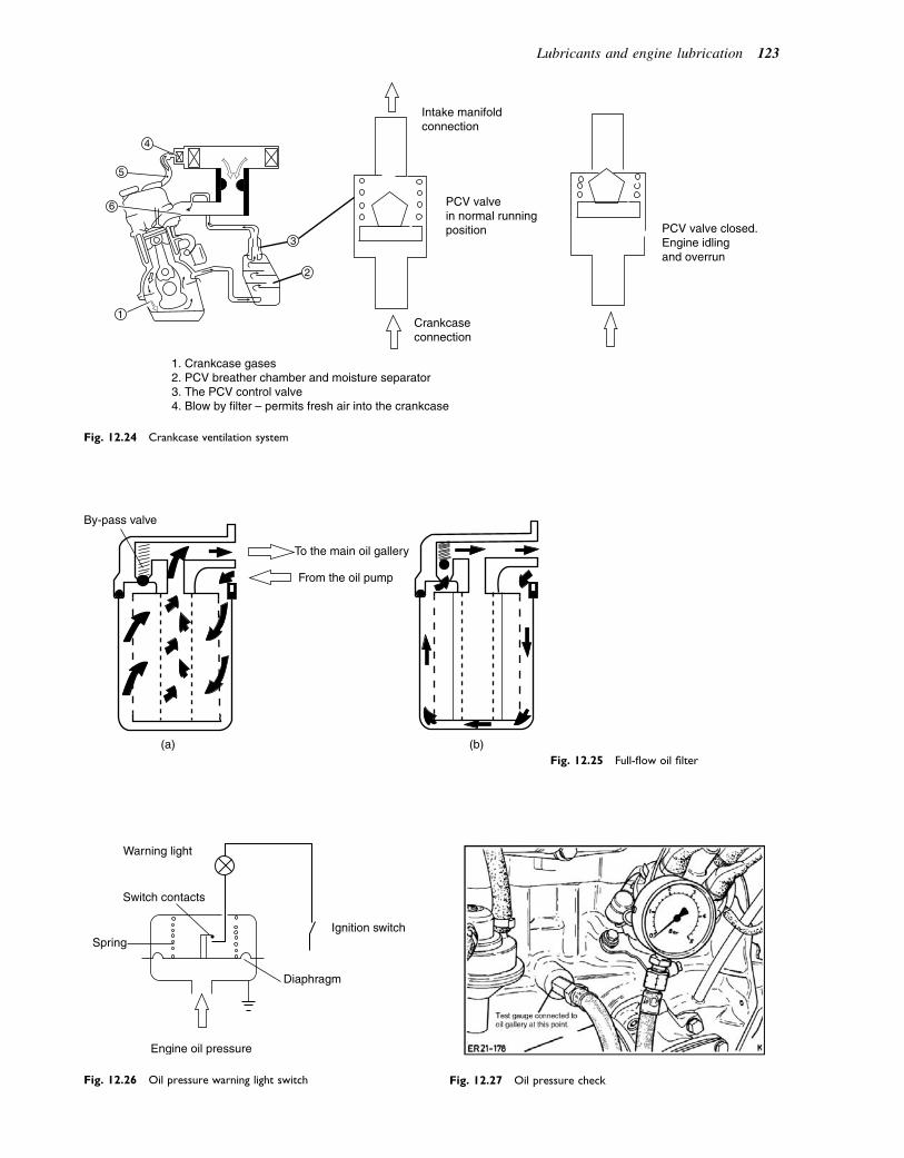
5
4
6
3
2
1
1. Crankcase gases2. PCV breather chamber and moisture separator3. The PCV control valve4. Blow by filter – permits fresh air into the crankcase
Crankcaseconnection
PCV valvein normal runningposition PCV valve closed.
Engine idlingand overrun
Intake manifoldconnection
Fig. 12.24 Crankcase ventilation system
By-pass valve
To the main oil gallery
From the oil pump
(a) (b)Fig. 12.25 Full-flow oil filter
Warning light
Switch contacts
Spring
Engine oil pressure
Diaphragm
Ignition switch
Fig. 12.26 Oil pressure warning light switch Fig. 12.27 Oil pressure check
Lubricants and engine lubrication 123

2. Figure 12.25 shows two views of a full-flow filter.Describe the function of the bypass valve. What isthe condition of the filter element that is shown inB? What routine service operation is performed inorder to prevent the occurrence shown in B?
3. In which position on the engine is the oil warninglight switch (Fig. 12.26) fitted? In the figure theswitch contacts are open; will the warning light beon or off?
4. Figure 12.27 shows a test gauge connected in placeof the oil pressure switch in order to make anaccurate check on the oil pressure under operatingconditions. On the engine shown the pressureshould be:� a minimum of 0.6 bar at idling speed� a minimum of 1.5 bar at 2000 rev/min.
What should be the engine temperature whenconducting the tests? Make a list of the factors thatmay case the oil pressure to be lower than thesefigures. What is the probable result of running anengine with oil pressure that is lower than theaccepted minimum?
5. The oil pressure gauge circuit shown in Fig. 12.28contains two bimetallic elements. What causes thesender unit switch contacts to close? How does thebimetallic element cause the gauge needle to move?What prevents the gauge needle from movingcompletely to the highest position when the senderswitch contacts are responding to a low oilpressure?
6. Figure 12.29 shows a system that is used to spray oilat a pressure of 2.5 bar on to the underside ofa piston. What is the reason for doing this? Whatpart of the system prevents oil being sprayed whenthe main oil pressure is less than 2.5 bar?
7. Describe, with the aid of a sketch, how an oil coolerof the type shown in Fig. 12.30 operates. Why issuch an oil cooler likely to be found ona turbocharged engine?
8. Why is the filter element in Fig. 12.31 convoluted asshown?
9. If a worn engine oil pump causes low oil pressure:(a) the oil pressure can be increased by increasing
the pressure exerted by the spring in the oilpressure-relief valve
(b) increasing the relief valve spring pressure willmake no difference
Oil pressure gauge
Bi-metallic strip
Battery
No oil pressure
Sender unit switch contacts
Ignitionswitch
Bi-metallic element in sender
Oil pressure applied
Fig. 12.28 Oil pressure gauge
MAIN OILGALLERY
CYLINDERBLOCK
OIL JET
Spring loaded valve
PISTON
Fig. 12.29 Oil sprayed on underside of piston
OIL COOLER
OIL FILTER
BY-PASSVALVE
FILTERBRACKET
Fig. 12.30 An oil-to-water cooler
124 A Practical Approach to Motor Vehicle Engineering and Maintenance

(c) the engine oil should be changed to one havinga higher viscosity index
(d) the bypass valve in the oil filter should berenewed.
10. A full-flow oil filter is fitted with a bypass valve:(a) to prevent excessive oil consumption(b) to allow oil to reach the main galleries in the
event of a filter blockage(c) as a substitute for an oil pressure-relief valve(d) to allow excess oil from the gallery to leak back
through the oil pump.11. Big-end bearings are lubricated:
(a) by oil mist that rises from agitation of oil in thesump
(b) by splash lubrication(c) by oil that is fed to them by oilways in the
crankshaft(d) by oilways drilled in the connecting rods.
Oil filter element
Fig. 12.31 Section of an oil filter element
Lubricants and engine lubrication 125
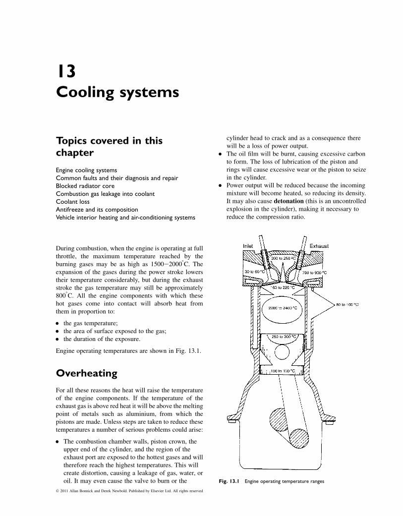
13Cooling systems
Topics covered in thischapter
Engine cooling systemsCommon faults and their diagnosis and repairBlocked radiator coreCombustion gas leakage into coolantCoolant lossAntifreeze and its compositionVehicle interior heating and air-conditioning systems
During combustion, when the engine is operating at fullthrottle, the maximum temperature reached by theburning gases may be as high as 1500e20008C. Theexpansion of the gases during the power stroke lowerstheir temperature considerably, but during the exhauststroke the gas temperature may still be approximately8008C. All the engine components with which thesehot gases come into contact will absorb heat fromthem in proportion to:
� the gas temperature;� the area of surface exposed to the gas;� the duration of the exposure.
Engine operating temperatures are shown in Fig. 13.1.
Overheating
For all these reasons the heat will raise the temperatureof the engine components. If the temperature of theexhaust gas is above red heat it will be above the meltingpoint of metals such as aluminium, from which thepistons are made. Unless steps are taken to reduce thesetemperatures a number of serious problems could arise:
� The combustion chamber walls, piston crown, theupper end of the cylinder, and the region of theexhaust port are exposed to the hottest gases and willtherefore reach the highest temperatures. This willcreate distortion, causing a leakage of gas, water, oroil. It may even cause the valve to burn or the
cylinder head to crack and as a consequence therewill be a loss of power output.
� The oil film will be burnt, causing excessive carbonto form. The loss of lubrication of the piston andrings will cause excessive wear or the piston to seizein the cylinder.
� Power output will be reduced because the incomingmixture will become heated, so reducing its density.It may also cause detonation (this is an uncontrolledexplosion in the cylinder), making it necessary toreduce the compression ratio.
Fig. 13.1 Engine operating temperature ranges
� 2011 Allan Bonnick and Derek Newbold. Published by Elsevier Ltd. All rights reserved
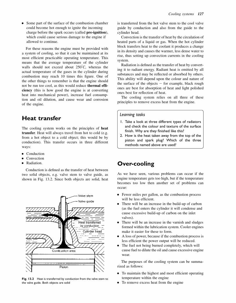
� Some part of the surface of the combustion chambercould become hot enough to ignite the incomingcharge before the spark occurs (called pre-ignition),which could cause serious damage to the engine ifallowed to continue.
For these reasons the engine must be provided witha system of cooling, so that it can be maintained at itsmost efficient practicable operating temperature. Thismeans that the average temperature of the cylinderwalls should not exceed about 2508C, whereas theactual temperature of the gases in the cylinder duringcombustion may reach 10 times this figure. One ofthe other things to remember is that the engine shouldnot be run too cool, as this would reduce thermal effi-ciency (this is how good the engine is at convertingheat into mechanical power), increase fuel consump-tion and oil dilution, and cause wear and corrosionof the engine.
Heat transfer
The cooling system works on the principles of heattransfer. Heat will always travel from hot to cold (e.g.from a hot object to a cold object; this would be byconduction). This transfer occurs in three differentways:
� Conduction� Convection� Radiation.
Conduction is defined as the transfer of heat betweentwo solid objects, e.g. valve stem to valve guide, asshown in Fig. 13.2. Since both objects are solid, heat
is transferred from the hot valve stem to the cool valveguide by conduction and also from the guide to thecylinder head.
Convection is the transfer of heat by the circulation ofheated parts of a liquid or gas. When the hot cylinderblock transfers heat to the coolant it produces a changein its density and causes the warmer, less dense water torise, thus setting up convection currents in the coolingsystem.
Radiation is defined as the transfer of heat by convert-ing it to radiant energy. Radiant heat is emitted by allsubstances and may be reflected or absorbed by others.This ability will depend upon the colour and nature ofthe surface of the objects e for example, black roughones are best for absorption of heat and light polishedones best for reflection of heat.
The cooling system relies on all three of theseprinciples to remove excess heat from the engine.
Learning tasks
1. Take a look at three different types of radiatorsand check the colour and texture of the surfacefinish. Why are they finished like this?
2. How is the heat taken away from the top of thepiston and spark plug? Which of the threemethods named above are used?
Over-cooling
As we have seen, various problems can occur if theengine temperature gets too high, but if the temperaturebecomes too low then another set of problems canoccur:
� Fewer miles per gallon, as the combustion processwill be less efficient.
� There will be an increase in the build-up of carbon(as the fuel enters the cylinder it will condense andcause excessive build-up of carbon on the inletvalves).
� There will be an increase in the varnish and sludgesformed within the lubrication system. Cooler enginesmake it easier for these to form.
� A loss of power, because if the combustion process isless efficient the power output will be reduced.
� The fuel not being burned completely, which willcause fuel to dilute the oil and cause excessive enginewear.
The purposes of the cooling system can be summa-rized as follows:
� To maintain the highest and most efficient operatingtemperature within the engine
� To remove excess heat from the engineFig. 13.2 Heat is transferred by conduction from the valve stem to
the valve guide. Both objects are solid
Cooling systems 127
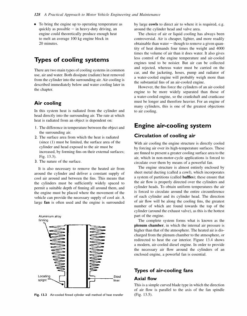
� To bring the engine up to operating temperature asquickly as possible e in heavy-duty driving, anengine could theoretically produce enough heatto melt an average 100 kg engine block in20 minutes.
Types of cooling systems
There are two main types of cooling systems in commonuse, air and water. Both dissipate (radiate) heat removedfrom the cylinder into the surrounding air. Air cooling isdescribed immediately below and water cooling later inthe chapter.
Air cooling
In this system heat is radiated from the cylinder andhead directly into the surrounding air. The rate at whichheat is radiated from an object is dependent on:
1. The difference in temperature between the object andthe surrounding air.
2. The surface area from which the heat is radiated(since (1) must be limited, the surface area of thecylinder and head exposed to the air must beincreased, by forming fins on their external surfaces;Fig. 13.3).
3. The nature of the surface.
It is also necessary to remove the heated air fromaround the cylinder and deliver a constant supply ofcool air around and between the fins. This means thatthe cylinders must be sufficiently widely spaced topermit a suitable depth of finning all around them, andthe engine must be placed where the movement of thevehicle can provide the necessary supply of cool air. Alarge fan is often used and the engine is surrounded
by large cowls to direct air to where it is required, e.g.around the cylinder head and valve area.
The choice of air or liquid cooling has always beencontroversial. Air is cheaper, lighter, and more readilyobtainable than water e though to remove a given quan-tity of heat demands four times the weight and 4000times the volume of air than it does water. It also givesless control of the engine temperature and air-cooledengines tend to be noisier. But air can be collectedand rejected, whereas water must be carried on thecar, and the jacketing, hoses, pump and radiator ofa water-cooled engine will probably weigh more thanthe substantial fins of an air-cooled engine.
However, the fins force the cylinders of an air-cooledengine to be more widely separated than those ofa water-cooled engine, so the crankshaft and crankcasemust be longer and therefore heavier. For an engine ofmany cylinders, this is one of the greatest objectionsto air cooling.
Engine air-cooling system
Circulation of cooling air
With air cooling the engine structure is directly cooledby forcing air over its high-temperature surfaces. Theseare finned to present a greater cooling surface area to theair, which in non-motor-cycle applications is forced tocirculate over them by means of a powerful fan.
The engine structure is almost entirely enclosed bysheet metal ducting (called a cowl), which incorporatesa system of partitions (called baffles); these ensure thatthe air flow is properly directed over the cylinders andcylinder heads. To obtain uniform temperatures the airis forced to circulate around the entire circumferenceof each cylinder and its cylinder head. The directionof air flow will be along the cooling fins, the greatestnumber of which are found towards the top of thecylinder (around the exhaust valve), as this is the hottestpart of the engine.
The complete system forms what is known as theplenum chamber, in which the internal air pressure ishigher than that of the atmosphere. The heated air is dis-charged from the plenum chamber to the atmosphere, orredirected to heat the car interior. Figure 13.4 showsa modern, air-cooled diesel engine. In order to providethe necessary air flow around the cylinders of anenclosed engine, a powerful fan is essential.
Types of air-cooling fans
Axial flow
This is a simple curved blade type in which the directionof air flow is parallel to the axis of the fan spindle(Fig. 13.5).Fig. 13.3 Air-cooled finned cylinder wall method of heat transfer
128 A Practical Approach to Motor Vehicle Engineering and Maintenance
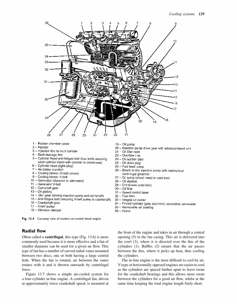
Radial flow
Often called a centrifugal, this type (Fig. 13.6) is morecommonly used because it is more effective and a fan ofsmaller diameter can be used for a given air flow. Thistype of fan has a number of curved radial vanes mountedbetween two discs, one or both having a large centralhole. When the fan is rotated, air between the vanesrotates with it and is thrown outwards by centrifugalforce.
Figure 13.7 shows a simple air-cooled system fora four-cylinder in-line engine. A centrifugal fan, drivenat approximately twice crankshaft speed, is mounted at
the front of the engine and takes in air through a centralopening (5) in the fan casing. This air is delivered intothe cowl (3), where it is directed over the fins of thecylinders (1). Baffles (2) ensure that the air passesbetween the fins, where it picks up heat, thus coolingthe cylinders.
The in-line engine is the most difficult to cool by air.V-type or horizontally opposed engines are easier to coolas the cylinders are spaced further apart to leave roomfor the crankshaft bearings and this allows more roombetween the cylinders for a good air flow, whilst at thesame time keeping the total engine length fairly short.
Fig. 13.4 Cut-away view of modern air-cooled diesel engine
Cooling systems 129
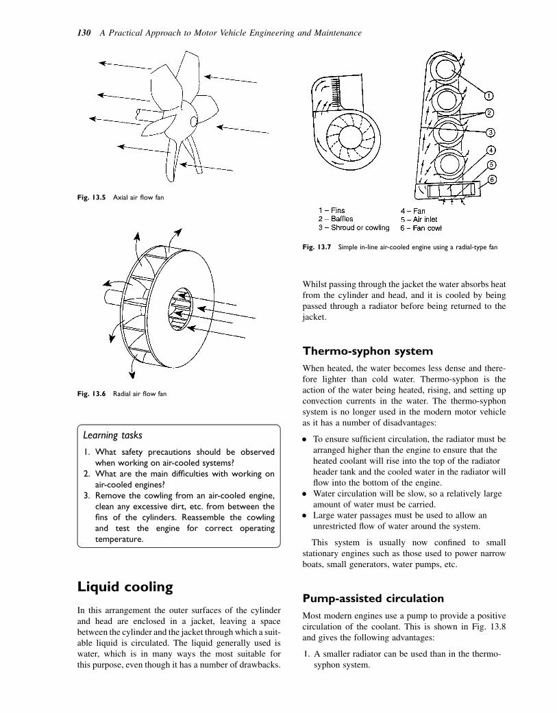
Learning tasks
1. What safety precautions should be observedwhen working on air-cooled systems?
2. What are the main difficulties with working onair-cooled engines?
3. Remove the cowling from an air-cooled engine,clean any excessive dirt, etc. from between thefins of the cylinders. Reassemble the cowlingand test the engine for correct operatingtemperature.
Liquid cooling
In this arrangement the outer surfaces of the cylinderand head are enclosed in a jacket, leaving a spacebetween the cylinder and the jacket through which a suit-able liquid is circulated. The liquid generally used iswater, which is in many ways the most suitable forthis purpose, even though it has a number of drawbacks.
Whilst passing through the jacket the water absorbs heatfrom the cylinder and head, and it is cooled by beingpassed through a radiator before being returned to thejacket.
Thermo-syphon system
When heated, the water becomes less dense and there-fore lighter than cold water. Thermo-syphon is theaction of the water being heated, rising, and setting upconvection currents in the water. The thermo-syphonsystem is no longer used in the modern motor vehicleas it has a number of disadvantages:
� To ensure sufficient circulation, the radiator must bearranged higher than the engine to ensure that theheated coolant will rise into the top of the radiatorheader tank and the cooled water in the radiator willflow into the bottom of the engine.
� Water circulation will be slow, so a relatively largeamount of water must be carried.
� Large water passages must be used to allow anunrestricted flow of water around the system.
This system is usually now confined to smallstationary engines such as those used to power narrowboats, small generators, water pumps, etc.
Pump-assisted circulation
Most modern engines use a pump to provide a positivecirculation of the coolant. This is shown in Fig. 13.8and gives the following advantages:
1. A smaller radiator can be used than in the thermo-syphon system.
Fig. 13.7 Simple in-line air-cooled engine using a radial-type fan
Fig. 13.6 Radial air flow fan
Fig. 13.5 Axial air flow fan
130 A Practical Approach to Motor Vehicle Engineering and Maintenance

2. Less coolant is carried as the water is circulatedfaster and therefore the heat is removed morequickly.
3. Smaller passages and hoses are used because of (2)above.
4. The radiator does not need to be above the level ofthe engine, giving a lower bonnet line; this also hasthe advantage of less wind resistance, giving a betterfuel consumption.
5. Because the water flow is given positivedirection, the engine will operate at a more eventemperature.
Comparison of air- andwater-cooled systems
Advantages of air cooling
� An air-cooled engine is generally lighter than anequivalent water-cooled engine.
� It warms up to its normal running temperature veryquickly.
� The engine can operate at a higher temperature thana water-cooled engine.
� The system is free from coolant leakage problemsand requires no maintenance.
� There is no risk of damage due to freezing of thecoolant in cold weather.
Disadvantages of air cooling
� A fan and suitable cowls are necessary to provide anddirect the air flow. The fan can be noisy and absorbsa large amount of engine power. The cowl makes itdifficult to get at various parts of the engine whenservicing is required.
� The engine is more liable to overheating underdifficult conditions than a water-cooled engine.
� Mechanical engine noises tend to be amplified by thefins.
� The cylinders usually have to be made separately toensure proper formation of the fins. This makes theengine more costly to manufacture.
� Cylinders must be spaced well apart to allowsufficient depth of fins.
� It is more difficult to arrange a satisfactory car-heating system.
Advantages of water cooling
� The temperatures throughout the engine are moreuniform, thus keeping distortion to a minimum.
� Cylinders can be placed closer together, making theengine more compact.
� Although a fan is usually fitted to force air throughthe radiator, it is much smaller than the type requiredfor an air-cooled engine. It therefore absorbs lesspower and is quieter in operation.
Fig. 13.8 Coolant is pumped from the water pump, through the cylinder block and heads, through the thermostat into the radiator, and back to
the water pump
Cooling systems 131
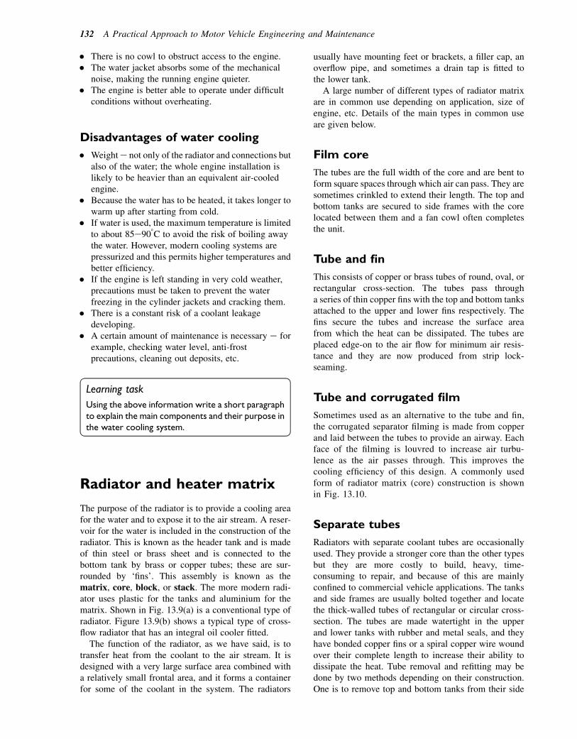
� There is no cowl to obstruct access to the engine.� The water jacket absorbs some of the mechanical
noise, making the running engine quieter.� The engine is better able to operate under difficult
conditions without overheating.
Disadvantages of water cooling
� Weighte not only of the radiator and connections butalso of the water; the whole engine installation islikely to be heavier than an equivalent air-cooledengine.
� Because the water has to be heated, it takes longer towarm up after starting from cold.
� If water is used, the maximum temperature is limitedto about 85e908C to avoid the risk of boiling awaythe water. However, modern cooling systems arepressurized and this permits higher temperatures andbetter efficiency.
� If the engine is left standing in very cold weather,precautions must be taken to prevent the waterfreezing in the cylinder jackets and cracking them.
� There is a constant risk of a coolant leakagedeveloping.
� A certain amount of maintenance is necessary e forexample, checking water level, anti-frostprecautions, cleaning out deposits, etc.
Learning task
Using the above information write a short paragraphto explain the main components and their purpose inthe water cooling system.
Radiator and heater matrix
The purpose of the radiator is to provide a cooling areafor the water and to expose it to the air stream. A reser-voir for the water is included in the construction of theradiator. This is known as the header tank and is madeof thin steel or brass sheet and is connected to thebottom tank by brass or copper tubes; these are sur-rounded by ‘fins’. This assembly is known as thematrix, core, block, or stack. The more modern radi-ator uses plastic for the tanks and aluminium for thematrix. Shown in Fig. 13.9(a) is a conventional type ofradiator. Figure 13.9(b) shows a typical type of cross-flow radiator that has an integral oil cooler fitted.
The function of the radiator, as we have said, is totransfer heat from the coolant to the air stream. It isdesigned with a very large surface area combined witha relatively small frontal area, and it forms a containerfor some of the coolant in the system. The radiators
usually have mounting feet or brackets, a filler cap, anoverflow pipe, and sometimes a drain tap is fitted tothe lower tank.
A large number of different types of radiator matrixare in common use depending on application, size ofengine, etc. Details of the main types in common useare given below.
Film core
The tubes are the full width of the core and are bent toform square spaces through which air can pass. They aresometimes crinkled to extend their length. The top andbottom tanks are secured to side frames with the corelocated between them and a fan cowl often completesthe unit.
Tube and fin
This consists of copper or brass tubes of round, oval, orrectangular cross-section. The tubes pass througha series of thin copper fins with the top and bottom tanksattached to the upper and lower fins respectively. Thefins secure the tubes and increase the surface areafrom which the heat can be dissipated. The tubes areplaced edge-on to the air flow for minimum air resis-tance and they are now produced from strip lock-seaming.
Tube and corrugated film
Sometimes used as an alternative to the tube and fin,the corrugated separator filming is made from copperand laid between the tubes to provide an airway. Eachface of the filming is louvred to increase air turbu-lence as the air passes through. This improves thecooling efficiency of this design. A commonly usedform of radiator matrix (core) construction is shownin Fig. 13.10.
Separate tubes
Radiators with separate coolant tubes are occasionallyused. They provide a stronger core than the other typesbut they are more costly to build, heavy, time-consuming to repair, and because of this are mainlyconfined to commercial vehicle applications. The tanksand side frames are usually bolted together and locatethe thick-walled tubes of rectangular or circular cross-section. The tubes are made watertight in the upperand lower tanks with rubber and metal seals, and theyhave bonded copper fins or a spiral copper wire woundover their complete length to increase their ability todissipate the heat. Tube removal and refitting may bedone by two methods depending on their construction.One is to remove top and bottom tanks from their side
132 A Practical Approach to Motor Vehicle Engineering and Maintenance

frames, the other is to spring the tubes in and out, whichis only possible because of their flexibility.
Separate expansion or header tanks
Separate expansion or header tanks are now commonlyused. These allow the radiator to be fitted lower thanthe engine and, on a commercial vehicle, to be fittedin a more accessible position for checking and refilling
the coolant. The tank is also used to reduce the risk ofaeration (this is air bubbles forming in the water) ofthe coolant when the engine is running. The early typesof radiators were all of the conventional type e forexample, the coolant flows from the top of the radiatorto the bottom (vertically). Many vehicles now usea cross-flow type in which the coolant flows horizon-tally through the core from the top of one side tankacross to the bottom of the other side tank, as shownin Fig. 13.11.
Fig. 13.9 (a) Conventional vertical flow radiator. (b) The parts of a standard cross-flow radiator
Cooling systems 133
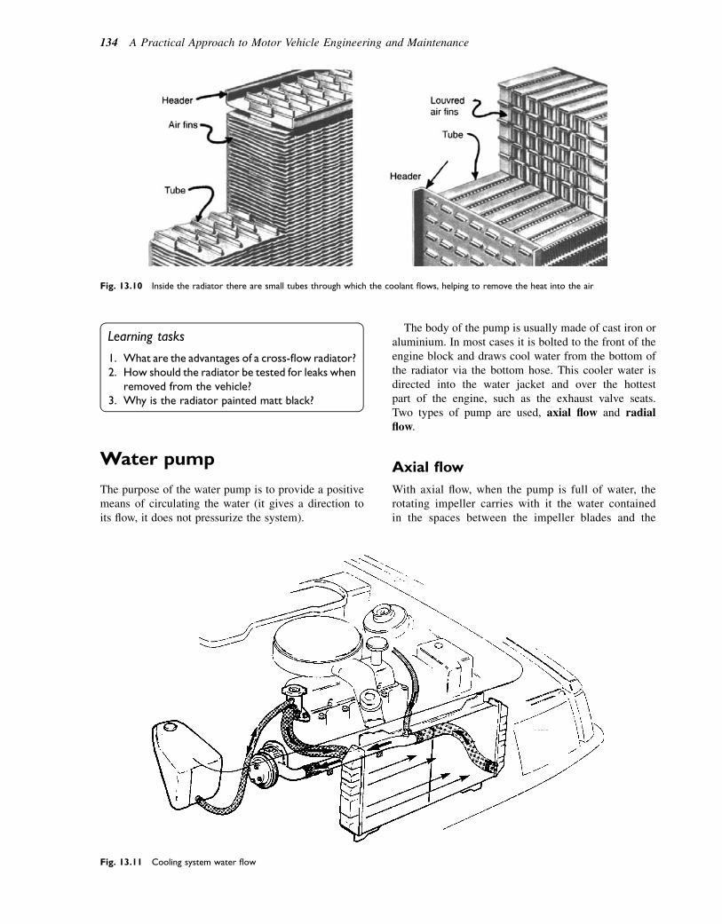
Learning tasks
1. What are the advantages of a cross-flow radiator?2. How should the radiator be tested for leaks when
removed from the vehicle?3. Why is the radiator painted matt black?
Water pump
The purpose of the water pump is to provide a positivemeans of circulating the water (it gives a direction toits flow, it does not pressurize the system).
The body of the pump is usually made of cast iron oraluminium. In most cases it is bolted to the front of theengine block and draws cool water from the bottom ofthe radiator via the bottom hose. This cooler water isdirected into the water jacket and over the hottestpart of the engine, such as the exhaust valve seats.Two types of pump are used, axial flow and radialflow.
Axial flow
With axial flow, when the pump is full of water, therotating impeller carries with it the water containedin the spaces between the impeller blades and the
Fig. 13.11 Cooling system water flow
Fig. 13.10 Inside the radiator there are small tubes through which the coolant flows, helping to remove the heat into the air
134 A Practical Approach to Motor Vehicle Engineering and Maintenance
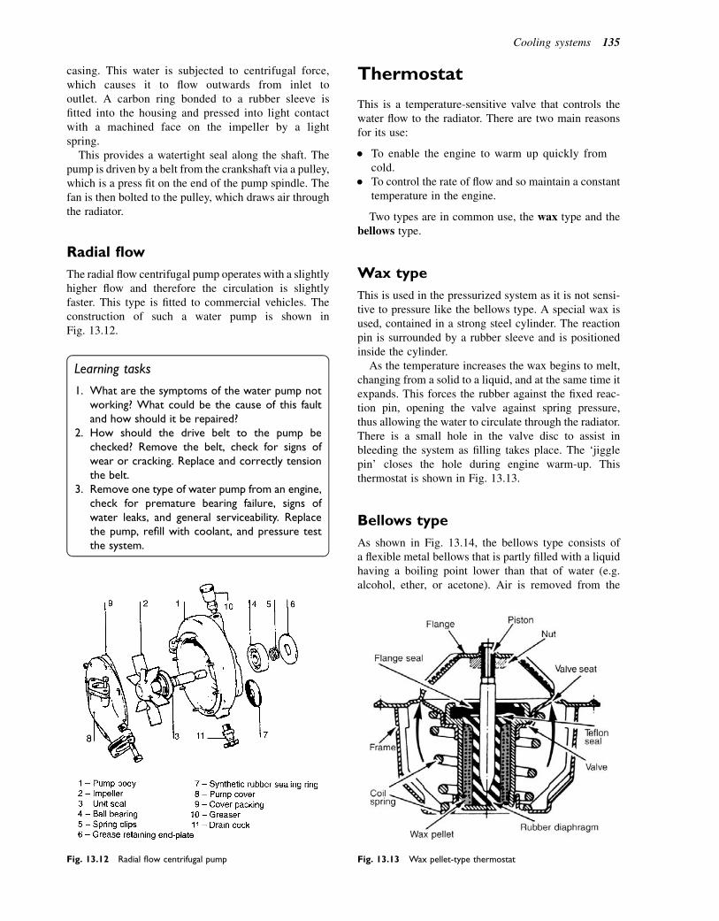
casing. This water is subjected to centrifugal force,which causes it to flow outwards from inlet tooutlet. A carbon ring bonded to a rubber sleeve isfitted into the housing and pressed into light contactwith a machined face on the impeller by a lightspring.
This provides a watertight seal along the shaft. Thepump is driven by a belt from the crankshaft via a pulley,which is a press fit on the end of the pump spindle. Thefan is then bolted to the pulley, which draws air throughthe radiator.
Radial flow
The radial flow centrifugal pump operates with a slightlyhigher flow and therefore the circulation is slightlyfaster. This type is fitted to commercial vehicles. Theconstruction of such a water pump is shown inFig. 13.12.
Learning tasks
1. What are the symptoms of the water pump notworking? What could be the cause of this faultand how should it be repaired?
2. How should the drive belt to the pump bechecked? Remove the belt, check for signs ofwear or cracking. Replace and correctly tensionthe belt.
3. Remove one type of water pump from an engine,check for premature bearing failure, signs ofwater leaks, and general serviceability. Replacethe pump, refill with coolant, and pressure testthe system.
Thermostat
This is a temperature-sensitive valve that controls thewater flow to the radiator. There are two main reasonsfor its use:
� To enable the engine to warm up quickly fromcold.
� To control the rate of flow and so maintain a constanttemperature in the engine.
Two types are in common use, the wax type and thebellows type.
Wax type
This is used in the pressurized system as it is not sensi-tive to pressure like the bellows type. A special wax isused, contained in a strong steel cylinder. The reactionpin is surrounded by a rubber sleeve and is positionedinside the cylinder.
As the temperature increases the wax begins to melt,changing from a solid to a liquid, and at the same time itexpands. This forces the rubber against the fixed reac-tion pin, opening the valve against spring pressure,thus allowing the water to circulate through the radiator.There is a small hole in the valve disc to assist inbleeding the system as filling takes place. The ‘jigglepin’ closes the hole during engine warm-up. Thisthermostat is shown in Fig. 13.13.
Bellows type
As shown in Fig. 13.14, the bellows type consists ofa flexible metal bellows that is partly filled with a liquidhaving a boiling point lower than that of water (e.g.alcohol, ether, or acetone). Air is removed from the
Fig. 13.12 Radial flow centrifugal pump Fig. 13.13 Wax pellet-type thermostat
Cooling systems 135

bellows, leaving only the liquid and its vapour. The pres-sure in the bellows is then only due to the vapour pres-sure of the liquid. This varies with temperature and isequal to atmospheric pressure at the boiling temperatureof the liquid, less at lower temperatures and more athigher temperatures. As the temperature of the waterincreases, the liquid in the bellows begins to turn toa vapour and increases in pressure; this expands thebellows and opens the valve, allowing water to pass tothe radiator.
Note
This type is not suitable for pressurized systems asthe valves are pressure sensitive. The wax elementtype does not have this disadvantage.
Testing thermostats
The thermostat cannot be repaired and so must bereplaced if found to be faulty. It can be tested by placingthe thermostat in a beaker of water and gradually heat-ing it. A thermometer is used to check the temperatureof the water (Fig. 13.15). The thermostat should begin
to open when the temperature marked on the valve isreached. An increase of approximately 10e208C willelapse before the valve is fully open.
Learning tasks
1. Write a schedule for removing, testing, andreplacing a thermostat that is suspected of beingfaulty.
2. What is the symptom, fault, cause, and remedialaction that should be taken when the drivercomplains of the heater blowing hot and cold?
3. Remove, test, and replace a thermostat accordingto your work schedule drawn up in (1) above.State the type of unit fitted, the temperature atwhich it opened/closed, and check with themanufacturer’s data.
Pressurized cooling systems
Pressurized cooling systems are used because they allowthe engine to operate at a higher temperature.Figure 13.16 shows the layout and main componentsof a modern pressurized system.
Pressure cap
The cap contains two valves; one is the pressure valvethe other is the vacuum valve (Fig. 13.17). As thetemperature of the water increases it expands and ina sealed system this expansion increases the pressureuntil it reaches the relief pressure of the cap. As thesystem cools down it contracts and opens the vacuumvalve, drawing in air. If no vacuum valve was fittedthe depression in the system, caused by the contractingeffect of the water as it cools, could cause the rubberhoses in the system to collapse. Most pressure capsoperate at 28e100 kN/m. The pressure is usuallystamped on the cap, indicating the maximum relief pres-sure for the system to which it is fitted. Figure 13.17(c)shows a pressure cap in the open position.
Safety note
Never remove the cap when the coolant tempera-ture is above 1008C as this will allow the water to boilviolently; the resulting jet of steam and water fromthe open filler can cause very serious scalds. Thesystem should be allowed to cool down and the capremoved slowly. It is designed so that the spring discremains seated on the top of the filler neck until afterthe seal has lifted. This allows the pressure to escapethrough the vent pipe before it can escape from themain opening.
Fig. 13.14 Bellows-type thermostat
Fig. 13.15 Thermostat suspended in water container
136 A Practical Approach to Motor Vehicle Engineering and Maintenance
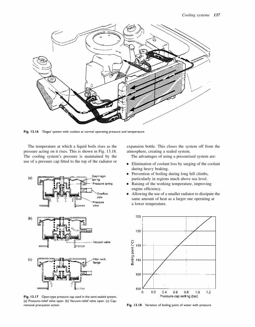
The temperature at which a liquid boils rises as thepressure acting on it rises. This is shown in Fig. 13.18.The cooling system’s pressure is maintained by theuse of a pressure cap fitted to the top of the radiator or
expansion bottle. This closes the system off from theatmosphere, creating a sealed system.
The advantages of using a pressurized system are:
� Elimination of coolant loss by surging of the coolantduring heavy braking.
� Prevention of boiling during long hill climbs,particularly in regions much above sea level.
� Raising of the working temperature, improvingengine efficiency.
� Allowing the use of a smaller radiator to dissipate thesame amount of heat as a larger one operating ata lower temperature.
Fig. 13.17 Open-type pressure cap used in the semi-sealed system.
(a) Pressure-relief valve open. (b) Vacuum-relief valve open. (c) Cap-
removal precaution action
Fig. 13.16 ‘Degas’ system with coolant at normal operating pressure and temperature
Fig. 13.18 Variation of boiling point of water with pressure
Cooling systems 137
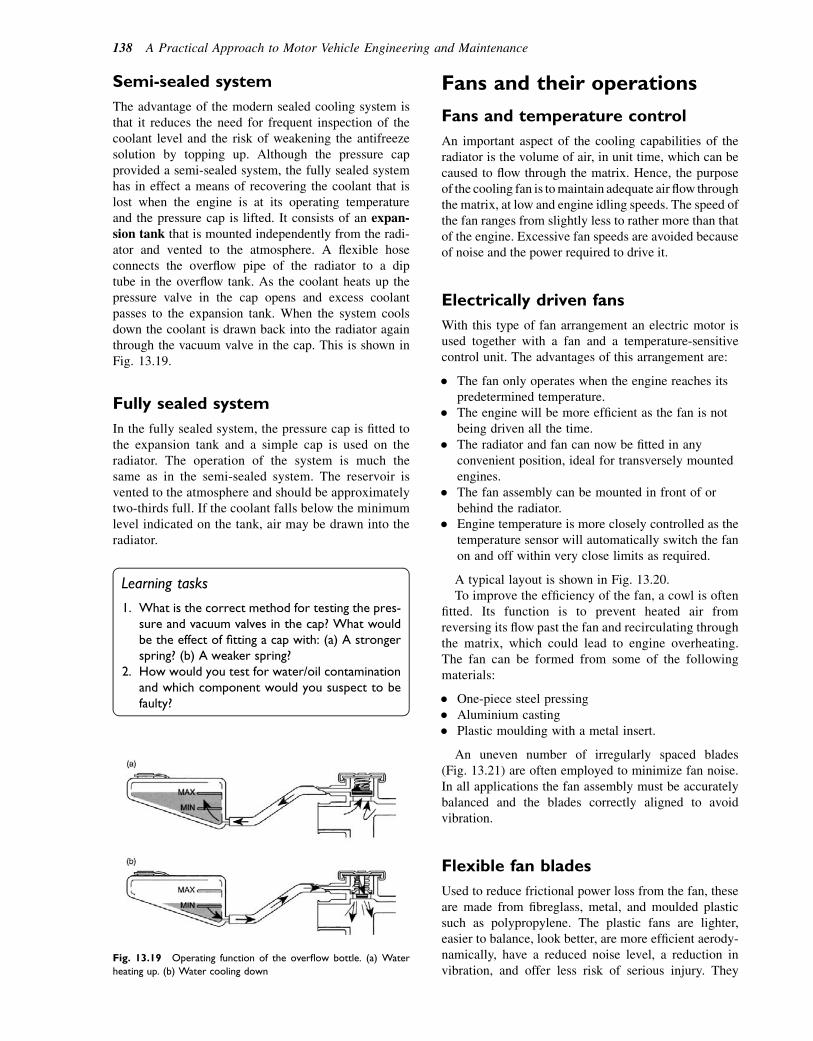
Semi-sealed system
The advantage of the modern sealed cooling system isthat it reduces the need for frequent inspection of thecoolant level and the risk of weakening the antifreezesolution by topping up. Although the pressure capprovided a semi-sealed system, the fully sealed systemhas in effect a means of recovering the coolant that islost when the engine is at its operating temperatureand the pressure cap is lifted. It consists of an expan-sion tank that is mounted independently from the radi-ator and vented to the atmosphere. A flexible hoseconnects the overflow pipe of the radiator to a diptube in the overflow tank. As the coolant heats up thepressure valve in the cap opens and excess coolantpasses to the expansion tank. When the system coolsdown the coolant is drawn back into the radiator againthrough the vacuum valve in the cap. This is shown inFig. 13.19.
Fully sealed system
In the fully sealed system, the pressure cap is fitted tothe expansion tank and a simple cap is used on theradiator. The operation of the system is much thesame as in the semi-sealed system. The reservoir isvented to the atmosphere and should be approximatelytwo-thirds full. If the coolant falls below the minimumlevel indicated on the tank, air may be drawn into theradiator.
Learning tasks
1. What is the correct method for testing the pres-sure and vacuum valves in the cap? What wouldbe the effect of fitting a cap with: (a) A strongerspring? (b) A weaker spring?
2. How would you test for water/oil contaminationand which component would you suspect to befaulty?
Fans and their operations
Fans and temperature control
An important aspect of the cooling capabilities of theradiator is the volume of air, in unit time, which can becaused to flow through the matrix. Hence, the purposeof the cooling fan is tomaintain adequate air flow throughthe matrix, at low and engine idling speeds. The speed ofthe fan ranges from slightly less to rather more than thatof the engine. Excessive fan speeds are avoided becauseof noise and the power required to drive it.
Electrically driven fans
With this type of fan arrangement an electric motor isused together with a fan and a temperature-sensitivecontrol unit. The advantages of this arrangement are:
� The fan only operates when the engine reaches itspredetermined temperature.
� The engine will be more efficient as the fan is notbeing driven all the time.
� The radiator and fan can now be fitted in anyconvenient position, ideal for transversely mountedengines.
� The fan assembly can be mounted in front of orbehind the radiator.
� Engine temperature is more closely controlled as thetemperature sensor will automatically switch the fanon and off within very close limits as required.
A typical layout is shown in Fig. 13.20.To improve the efficiency of the fan, a cowl is often
fitted. Its function is to prevent heated air fromreversing its flow past the fan and recirculating throughthe matrix, which could lead to engine overheating.The fan can be formed from some of the followingmaterials:
� One-piece steel pressing� Aluminium casting� Plastic moulding with a metal insert.
An uneven number of irregularly spaced blades(Fig. 13.21) are often employed to minimize fan noise.In all applications the fan assembly must be accuratelybalanced and the blades correctly aligned to avoidvibration.
Flexible fan blades
Used to reduce frictional power loss from the fan, theseare made from fibreglass, metal, and moulded plasticsuch as polypropylene. The plastic fans are lighter,easier to balance, look better, are more efficient aerody-namically, have a reduced noise level, a reduction invibration, and offer less risk of serious injury. They
Fig. 13.19 Operating function of the overflow bottle. (a) Water
heating up. (b) Water cooling down
138 A Practical Approach to Motor Vehicle Engineering and Maintenance
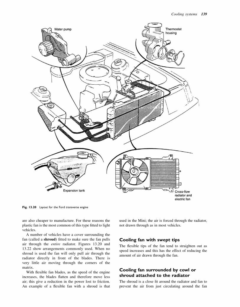
are also cheaper to manufacture. For these reasons theplastic fan is the most common of this type fitted to lightvehicles.
A number of vehicles have a cover surrounding thefan (called a shroud) fitted to make sure the fan pullsair through the entire radiator. Figures 13.20 and13.22 show arrangements commonly used. When noshroud is used the fan will only pull air through theradiator directly in front of the blades. There isvery little air moving through the corners of thematrix.
With flexible fan blades, as the speed of the engineincreases, the blades flatten and therefore move lessair; this give a reduction in the power lost to friction.An example of a flexible fan with a shroud is that
used in the Mini; the air is forced through the radiator,not drawn through as in most vehicles.
Cooling fan with swept tips
The flexible tips of the fan tend to straighten out asspeed increases and this has the effect of reducing theamount of air drawn through the fan.
Cooling fan surrounded by cowl orshroud attached to the radiator
The shroud is a close fit around the radiator and fan toprevent the air from just circulating around the fan
Fig. 13.20 Layout for the Ford transverse engine
Cooling systems 139
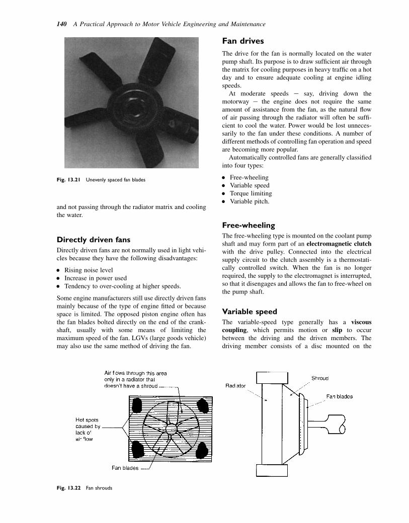
and not passing through the radiator matrix and coolingthe water.
Directly driven fans
Directly driven fans are not normally used in light vehi-cles because they have the following disadvantages:
� Rising noise level� Increase in power used� Tendency to over-cooling at higher speeds.
Some engine manufacturers still use directly driven fansmainly because of the type of engine fitted or becausespace is limited. The opposed piston engine often hasthe fan blades bolted directly on the end of the crank-shaft, usually with some means of limiting themaximum speed of the fan. LGVs (large goods vehicle)may also use the same method of driving the fan.
Fan drives
The drive for the fan is normally located on the waterpump shaft. Its purpose is to draw sufficient air throughthe matrix for cooling purposes in heavy traffic on a hotday and to ensure adequate cooling at engine idlingspeeds.
At moderate speeds e say, driving down themotorway e the engine does not require the sameamount of assistance from the fan, as the natural flowof air passing through the radiator will often be suffi-cient to cool the water. Power would be lost unneces-sarily to the fan under these conditions. A number ofdifferent methods of controlling fan operation and speedare becoming more popular.
Automatically controlled fans are generally classifiedinto four types:
� Free-wheeling� Variable speed� Torque limiting� Variable pitch.
Free-wheeling
The free-wheeling type is mounted on the coolant pumpshaft and may form part of an electromagnetic clutchwith the drive pulley. Connected into the electricalsupply circuit to the clutch assembly is a thermostati-cally controlled switch. When the fan is no longerrequired, the supply to the electromagnet is interrupted,so that it disengages and allows the fan to free-wheel onthe pump shaft.
Variable speed
The variable-speed type generally has a viscouscoupling, which permits motion or slip to occurbetween the driving and the driven members. Thedriving member consists of a disc mounted on the
Fig. 13.22 Fan shrouds
Fig. 13.21 Unevenly spaced fan blades
140 A Practical Approach to Motor Vehicle Engineering and Maintenance

pump shaft. Attached to the fan is a sealed cylindricalcasing or chamber, freely mounted on the pump shaft.The driving disc revolves within the coupling chamber,which is partially filled with a highly stable siliconefluid (this means it retains a nearly constant viscositywith varying operating temperatures). The disc initiallyrevolves in the stationary mass of fluid and sets upa drag, so that the fluid begins to circulate in thechamber. As a result of centrifugal force it movesoutwards to fill the gaps between the drive faces of thecoupling members. Since these faces are very close toone another, drive is transmitted between them by theviscous drag of the silicone fluid. This drag is main-tained with increasing fan speed, until the resisting tor-que imposed upon the fan by the air flow rises to anextent that causes shear breakdown of the fluid film,and the coupling slips. Fan speed is thus controlled bythe slipping action of the coupling, which is predeter-mined by the viscosity of the fluid and the degree towhich the coupling is filled. Where no provision ismade for the quantity of oil, the coupling is termed a tor-que-limiting type. The layout of a viscous fan drive isshown in Fig. 13.23.
Torque limiting
The torque-limiting type has the disadvantage of oper-ating within a fixed speed range, regardless of coolingsystem demands. Thus, air circulation may be inade-quate when car speed is low and engine speed is high.
To overcome these difficulties, a temperature-sensitivefan control is used in some installations.
Variable pitch
In the variable-pitch fan the volume of air displaced iscontrolled by twisting its blades. The term pitch isconsidered as the distance the blade can twist, if itwere turning one revolution in a solid substance (thatis with no slip taking place). When the least amountof cooling is required, the blades are automaticallyadjusted to a low pitch, thereby reducing airflow toa minimum. The variable-pitch fan may be actuatedby one of the following methods:
� Centrifugal� Torque limiting� Thermostatic means.
An alternative to the engine-driven fan is a separateelectrically driven fan, which can be controlled auto-matically by the thermostat that responds to changesin engine coolant temperature. Although fan installa-tions of this type absorb no engine power, they doimpose an electrical load upon the car battery. Ithas a fixed higher operating speed and it may benoisier than a conventional driven fan, but it has theadvantages of greater convenience of mountingposition.
Learning tasks
1. Give reasons for the use of an electrically drivenfan over other methods of operation.
2. Draw up in logical sequence the way an electricfan should be tested, apart from running theengine up to its normal operating temperature.
3. How should a viscous coupling be tested/repaired?
Radiator blinds and shutters
A very simple arrangement of controlling the air flowthrough the radiator is shown in Fig. 13.24. A spring-loaded roller blind is carried at the lower end of a rect-angular channel-section frame attached to the front ofthe radiator. A simple cable control raises the blind toclose off as much of the radiator as may be necessaryto maintain the correct running temperature of theengine. This is normally operated by the driver frominside the cab.
Another method of controlling the air flow is by theuse of a shutter. This operates in a similar way to a vene-tian window blind, each shutter rotating on a separateshaft. Mounted in front of the radiator it can be manuallyor thermostatically operated.
Fig. 13.23 Simplified diagram showing internal details of a viscous
fan drive
Cooling systems 141
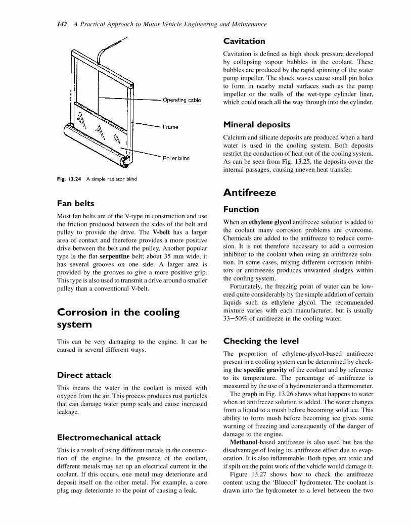
Fan belts
Most fan belts are of the V-type in construction and usethe friction produced between the sides of the belt andpulley to provide the drive. The V-belt has a largerarea of contact and therefore provides a more positivedrive between the belt and the pulley. Another populartype is the flat serpentine belt; about 35 mm wide, ithas several grooves on one side. A larger area isprovided by the grooves to give a more positive grip.This type is also used to transmit a drive around a smallerpulley than a conventional V-belt.
Corrosion in the coolingsystem
This can be very damaging to the engine. It can becaused in several different ways.
Direct attack
This means the water in the coolant is mixed withoxygen from the air. This process produces rust particlesthat can damage water pump seals and cause increasedleakage.
Electromechanical attack
This is a result of using different metals in the construc-tion of the engine. In the presence of the coolant,different metals may set up an electrical current in thecoolant. If this occurs, one metal may deteriorate anddeposit itself on the other metal. For example, a coreplug may deteriorate to the point of causing a leak.
Cavitation
Cavitation is defined as high shock pressure developedby collapsing vapour bubbles in the coolant. Thesebubbles are produced by the rapid spinning of the waterpump impeller. The shock waves cause small pin holesto form in nearby metal surfaces such as the pumpimpeller or the walls of the wet-type cylinder liner,which could reach all the way through into the cylinder.
Mineral deposits
Calcium and silicate deposits are produced when a hardwater is used in the cooling system. Both depositsrestrict the conduction of heat out of the cooling system.As can be seen from Fig. 13.25, the deposits cover theinternal passages, causing uneven heat transfer.
Antifreeze
Function
When an ethylene glycol antifreeze solution is added tothe coolant many corrosion problems are overcome.Chemicals are added to the antifreeze to reduce corro-sion. It is not therefore necessary to add a corrosioninhibitor to the coolant when using an antifreeze solu-tion. In some cases, mixing different corrosion inhibi-tors or antifreezes produces unwanted sludges withinthe cooling system.
Fortunately, the freezing point of water can be low-ered quite considerably by the simple addition of certainliquids such as ethylene glycol. The recommendedmixture varies with each manufacturer, but is usually33e50% of antifreeze in the cooling water.
Checking the level
The proportion of ethylene-glycol-based antifreezepresent in a cooling system can be determined by check-ing the specific gravity of the coolant and by referenceto its temperature. The percentage of antifreeze ismeasured by the use of a hydrometer and a thermometer.
The graph in Fig. 13.26 shows what happens to waterwhen an antifreeze solution is added. The water changesfrom a liquid to a mush before becoming solid ice. Thisability to form mush before becoming ice gives somewarning of freezing and consequently of the danger ofdamage to the engine.
Methanol-based antifreeze is also used but has thedisadvantage of losing its antifreeze effect due to evap-oration. It is also inflammable. Both types are toxic andif spilt on the paint work of the vehicle would damage it.
Figure 13.27 shows how to check the antifreezecontent using the ‘Bluecol’ hydrometer. The coolant isdrawn into the hydrometer to a level between the two
Fig. 13.24 A simple radiator blind
142 A Practical Approach to Motor Vehicle Engineering and Maintenance
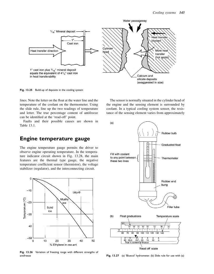
lines. Note the letter on the float at the water line and thetemperature of the coolant on the thermometer. Usingthe slide rule, line up the two readings of temperatureand letter. The true percentage content of antifreezecan be identified at the ‘read-off’ point.
Faults and their possible causes are shown inTable 13.1.
Engine temperature gauge
The engine temperature gauge permits the driver toobserve engine operating temperature. In the tempera-ture indicator circuit shown in Fig. 13.28, the mainfeatures are the thermal type gauge, the negativetemperature coefficient sensor (thermistor), the voltagestabilizer (regulator), and the interconnecting circuit.
The sensor is normally situated in the cylinder head ofthe engine and the sensing element is surrounded bycoolant. In a typical cooling system sensor, the resis-tance of the sensing element varies from approximately
Fig. 13.25 Build-up of deposits in the cooling system
Fig. 13.27 (a) ‘Bluecol’ hydrometer. (b) Slide rule for use with (a)
Fig. 13.26 Variation of freezing range with different strengths of
antifreeze
Cooling systems 143

230 ohms at 508C to approximately 20 ohms at 1108C.This variation of resistance causes the current flowingthrough the bimetallic element of the gauge to vary.The variation of current causes the temperature of thebimetallic element to change. The change of tempera-ture causes the bimetallic element to bend and so causesthe gauge pointer to move to indicate coolant tempera-ture. Because the operation of the gauge is dependenton a steady voltage being applied, the circuit includesa vibrating contact voltage stabilizer, which also relieson a bimetallic strip for its operation.
Learning tasks
1. Explain in your own words what is meant bysemiconductor.
2. How should the temperature sensor/transmitterbe checked for correct operation? Name anyspecial equipment that might be required.
3. Remove a temperature sensor and test for elec-trical resistance, both when cold and when hot.Note the readings and check your results withthe manufacturer’s data. Make recommendationson serviceability.
4. Where in the cooling system would a tempera-ture sensor be located? Why would it be fittedin this position?
Engine core plugs
These are fitted for the following reasons:
� They may blank off the holes left by the jacket coresduring casting or machining.
Table 13.1 Liquid cooling systems fault chart
Fault Possible cause
External
leakage
1. Loose hose clips or split rubber hose
2. Damaged radiator (cracked joints or
corroded core)
3. Water pump leaking (bearing worn)
4. Corroded core plugs
5. Damaged gaskets
6. Interior heater, hoses, valves
7. Temperature sensor connection leaking
Internal
leakage
1. Defective cylinder head gasket
2. Cylinder head not correctly tightened
3. Cracked water jacket internal wall
4. Defective cylinder liner seals
Water loss 1. Boiling
2. Leaks e internal and external
3. Restriction in radiator
4. Airways in radiator matrix blocked
Dirty
coolant
(corrosion)
1. Excessive impurity in coolant water
2. Infrequent draining and flushing of system
(where required)
3. Incorrect antifreeze mixtures
4. Lack of inhibitor
Overheating 1. Loose, broken, worn or incorrect fan-belt
tension
2. Defective thermostat
3. Water pump impeller loose on shaft
4. Restricted circulation e through radiator,
hoses, etc.
5. Radiator airways choked
6. Incorrect ignition timing
7. Incorrect valve timing
8. Tight engine
9. Low oil level
10. Insufficient coolant in system
Over-
cooling
1. Defective thermostat
2. Temperature gauge incorrect
3. Electric fan operating continuously
Battery
Ignition switch
Heating wire
Voltage regulator
Bimetallicelement
Cold Hot
Indicator
Sensor
Fig. 13.28 A thermal-type gauge and voltage regulator
144 A Practical Approach to Motor Vehicle Engineering and Maintenance
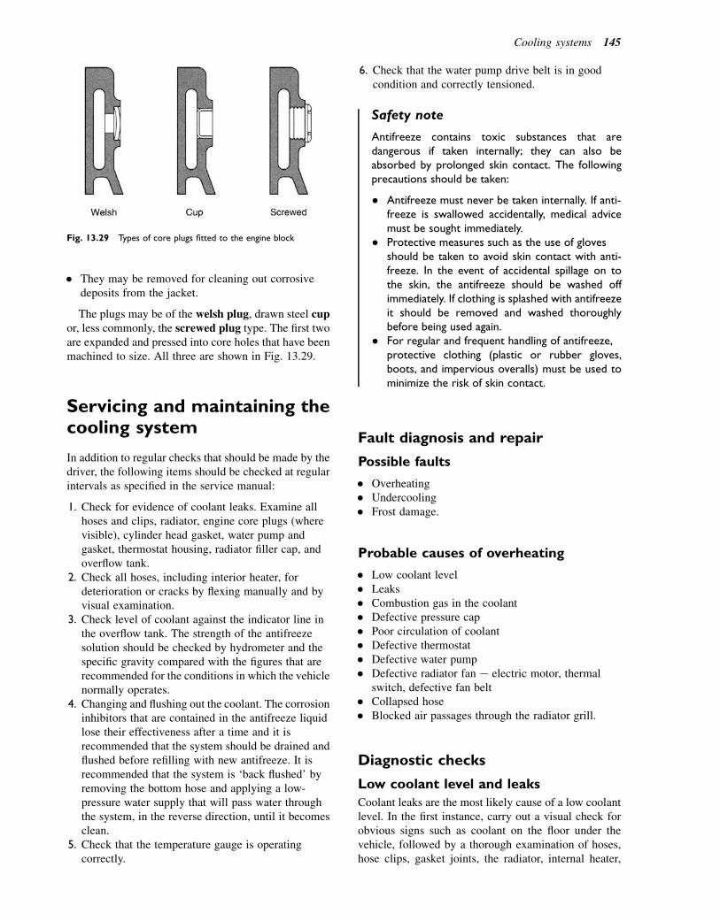
� They may be removed for cleaning out corrosivedeposits from the jacket.
The plugs may be of the welsh plug, drawn steel cupor, less commonly, the screwed plug type. The first twoare expanded and pressed into core holes that have beenmachined to size. All three are shown in Fig. 13.29.
Servicing and maintaining thecooling system
In addition to regular checks that should be made by thedriver, the following items should be checked at regularintervals as specified in the service manual:
1. Check for evidence of coolant leaks. Examine allhoses and clips, radiator, engine core plugs (wherevisible), cylinder head gasket, water pump andgasket, thermostat housing, radiator filler cap, andoverflow tank.
2. Check all hoses, including interior heater, fordeterioration or cracks by flexing manually and byvisual examination.
3. Check level of coolant against the indicator line inthe overflow tank. The strength of the antifreezesolution should be checked by hydrometer and thespecific gravity compared with the figures that arerecommended for the conditions in which the vehiclenormally operates.
4. Changing and flushing out the coolant. The corrosioninhibitors that are contained in the antifreeze liquidlose their effectiveness after a time and it isrecommended that the system should be drained andflushed before refilling with new antifreeze. It isrecommended that the system is ‘back flushed’ byremoving the bottom hose and applying a low-pressure water supply that will pass water throughthe system, in the reverse direction, until it becomesclean.
5. Check that the temperature gauge is operatingcorrectly.
6. Check that the water pump drive belt is in goodcondition and correctly tensioned.
Safety note
Antifreeze contains toxic substances that aredangerous if taken internally; they can also beabsorbed by prolonged skin contact. The followingprecautions should be taken:
� Antifreeze must never be taken internally. If anti-freeze is swallowed accidentally, medical advicemust be sought immediately.
� Protective measures such as the use of glovesshould be taken to avoid skin contact with anti-freeze. In the event of accidental spillage on tothe skin, the antifreeze should be washed offimmediately. If clothing is splashed with antifreezeit should be removed and washed thoroughlybefore being used again.
� For regular and frequent handling of antifreeze,protective clothing (plastic or rubber gloves,boots, and impervious overalls) must be used tominimize the risk of skin contact.
Fault diagnosis and repair
Possible faults
� Overheating� Undercooling� Frost damage.
Probable causes of overheating
� Low coolant level� Leaks� Combustion gas in the coolant� Defective pressure cap� Poor circulation of coolant� Defective thermostat� Defective water pump� Defective radiator fan e electric motor, thermal
switch, defective fan belt� Collapsed hose� Blocked air passages through the radiator grill.
Diagnostic checks
Low coolant level and leaks
Coolant leaks are the most likely cause of a low coolantlevel. In the first instance, carry out a visual check forobvious signs such as coolant on the floor under thevehicle, followed by a thorough examination of hoses,hose clips, gasket joints, the radiator, internal heater,
Fig. 13.29 Types of core plugs fitted to the engine block
Cooling systems 145

and the water pump. If these checks are not conclusive,further checks such as the system pressure check can beapplied.
A cooling system pressure check
Testing the pressure cap
The cooling system pressure cap can be tested by meansof the hand-held apparatus shown in Fig. 13.30. Theapparatus consists of a small hand-operated pump,a pressure gauge, and some adaptors that permit thepressure cap to be attached to it. When securelyattached, the pressure is raised to its maximum andthen recorded for comparison with the engine manufac-turer’s data, or the figure that is normally stamped on thepressure cap.
Pressure testing the entire system
The pressure cap test instrument can be used to place thecooling system under pressure, as shown in Fig. 13.31.
The equipment for this test contains the hoses andadaptors that permit the instrument to be securelyattached to the cooling system in place of the pressurecap. The pressure is then applied by means of thepump until it reaches the recommended test pressurewhich, in this example is 1.4 bar (20 lbf/in2). This pres-sure may be different for other systems and it should bechecked against the engine manual before the testproceeds. Once the system has been brought to the rec-ommended pressure it is held there for approximately
10 seconds. This should be followed by visual examina-tion of all possible leakage points.
Combustion gas leaking into coolant
Combustion gas may enter the cooling system by way ofa defective cylinder head gasket, a leaking wet linerseal, a cracked cylinder head or block. If combustiongas is leaking into the cooling system it will give riseto overheating and loss of coolant. The presence ofcombustion gas in the coolant can be detected by severalmethods, which include the following:
� The cylinder leakage test� Chemical analysis.
The cylinder leakage test
The cylinder leakage test (see Fig. 13.32) is performedby applying compressed air to the cylinders throughan adaptor that fits into the spark plug or injector hole.The equipment for this test contains a pressure gaugeand a leakage meter that shows leakage as a percentage.When all preliminary work has been completed, theadaptor and gauges are attached to the engine andthe compressed air pressure is raised to approximately7 bar (100 lbf/in2). With the cooling system pressurecap removed, any leak from the cylinders into thecooling system should be evident.
This test should only be conducted in accordance withthe manufacturer’s instructions.
Chemical analysis of coolant to check forcombustion leaks
The upper chamber of the apparatus is filled with thetest fluid up to the level that is indicated on the side ofthe vessel. A sample of steam from the engine coolingsystem is drawn into the upper sampling chamber andit is allowed to percolate through the test fluid.The test fluid is coloured blue and it changes toyellow if combustion gas (CO2) is detected in thecoolant.
Pressure cap or adaptor
Pressure gaugeHand operatedpump
Fig. 13.30 A pressure cap tester (Ford)
Connection tocompressed airsupply
Pressureregulatingvalve
Pressure gauge
Leak percentage
Hose connects to enginecylinder
Fig. 13.32 Cylinder leakage test kit (Sealey garage equipment)
Pressure tester
Adaptorand hoseconnection
Engine
Connected in place of cooling system pressure cap
Fig. 13.31 The cooling system pressure test (Ford)
146 A Practical Approach to Motor Vehicle Engineering and Maintenance

The apparatus shown in Fig. 13.33 is supplied bySealey Power Products and a full description togetherwith instructions for use can be seen on their websiteat sealey.co.uk.
Combustion gas leaks into the engine coolant mayalso be accompanied by coolant entering the combus-tion chamber; if this is the case it will probably causethe engine to misfire and emit white smoke from theexhaust system.
Poor circulation of coolant
Some probable causes of poor coolant circulation are:
� Defective thermostat� Defective water pump� Collapsed hose� Defective radiator fan e electric motor, thermal
switch, defective fan belt� Blocked coolant passages in radiator and engine.
Defective thermostat
If the thermostat is stuck in the closed, or partly closed,position it will seriously impede coolant flow and willquickly cause the engine to overheat. At the oppositeextreme, a thermostat that is stuck in the open positionmay cause delay in the engine reaching its normalworking temperature, with consequent effects on coldrunning performance of the engine. The operation ofthe thermostat can be checked with simple equipmentas shown in Fig. 13.15.
The water is gradually heated while the temperatureis observed; the opening of the valve can be observedas the valve begins to move away from its frame. Thevalve will begin to open at approximately 808C, or ata figure that will be found in the appropriate servicemanual.
Defective water pump
Should the water pump (Fig. 13.34) bearings becomeworn, the shaft will drop out of alignment and thiswill damage the seal; this is the most likely cause ofcoolant leakage. Any leakage from the pump shouldbe visible in the region where the pump shaft protrudesfrom the casing. When the pump drive belt is removed itshould be possible to check for bearing wear byapplying a rocking action to the drive pulley. The drivebelt and pulley should also be checked to make sure thatthey are not worn and when the belt is refitted its tensionshould be set correctly to ensure that it does not imposeexcessive stress on the bearings.
Defective fan
The belt drive to the cooling fan may slip because it,or the pulley, is worn. The belt should not be too deepin the V-groove so that it touches the base of the groove.This may be caused by wear of the belt and it can bechecked visually e the V-groove can be checked byplacing an unworn belt in it to see if it is resting in thecorrect position. The belt itself should be tensionedenough to prevent slip, but not too tight so that it placesstress on the pump bearings.
Electric fan
Electric cooling fans were originally controlled bya thermal switch, mounted in the radiator header tank,that reacted to changes in engine temperature. Becausethey only operate when the temperature requires themto, they absorb less engine power than the belt-drivenalternative. The electric cooling fan is designed tocome on at about 958C and turn off at about 908C.
In computer-managed engine controls, the electroniccontrol module (ECM) fan circuit (Fig. 13.35) may bedesigned so that the fan may continue running afterthe engine is switched off, to provide after cooling. Inthe system shown in Fig. 13.36 the fan can be operatedat two different speeds: a low speed where the fan motor
Upper chamber containsfluid which changescolour if CO2 is found inthe coolent
Filler cap adaptor
Fig. 13.33 Combustion gas leak detector (Sealey)
Pump seal
Pump shaft
Drive pulleyflange
Bearings
Impeller
Fig. 13.34 A typical coolant pump
Cooling systems 147
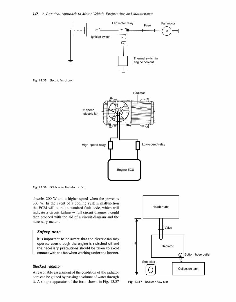
absorbs 200 W and a higher speed when the power is300 W. In the event of a cooling system malfunctionthe ECM will output a standard fault code, which willindicate a circuit failure e full circuit diagnosis couldthen proceed with the aid of a circuit diagram and thenecessary meters.
Safety note
It is important to be aware that the electric fan mayoperate even though the engine is switched off andthe necessary precautions should be taken to avoidcontact with the fan when working under the bonnet.
Blocked radiator
A reasonable assessment of the condition of the radiatorcore can be gained by passing a volume of water throughit. A simple apparatus of the form shown in Fig. 13.37
Fig. 13.36 ECM-controlled electric fan
Ignition switch
Fan motor relayFuse
Fan motor
Thermal switch inengine coolant
M
Fig. 13.35 Electric fan circuit
Radiator
Stop clock
Bottom hose outlet
Collection tank
H
Valve
Header tank
Fig. 13.37 Radiator flow test
148 A Practical Approach to Motor Vehicle Engineering and Maintenance
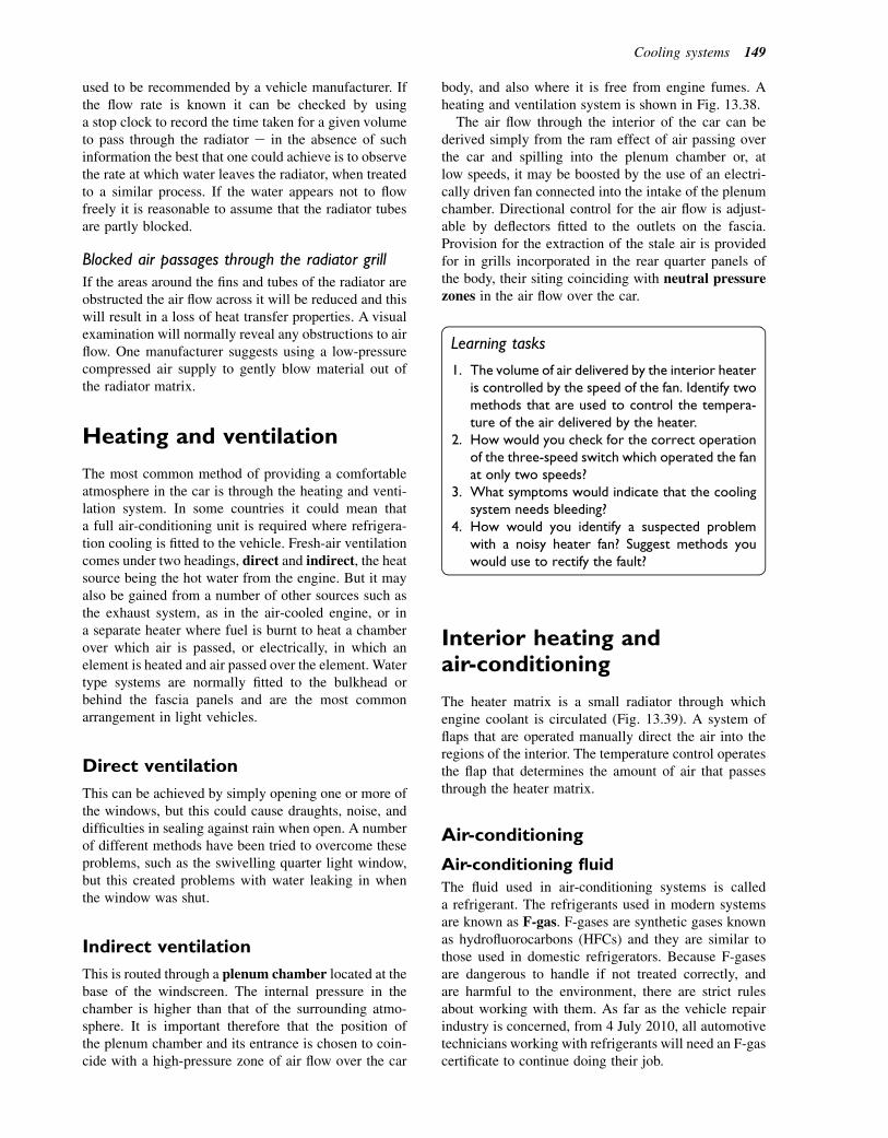
used to be recommended by a vehicle manufacturer. Ifthe flow rate is known it can be checked by usinga stop clock to record the time taken for a given volumeto pass through the radiator e in the absence of suchinformation the best that one could achieve is to observethe rate at which water leaves the radiator, when treatedto a similar process. If the water appears not to flowfreely it is reasonable to assume that the radiator tubesare partly blocked.
Blocked air passages through the radiator grill
If the areas around the fins and tubes of the radiator areobstructed the air flow across it will be reduced and thiswill result in a loss of heat transfer properties. A visualexamination will normally reveal any obstructions to airflow. One manufacturer suggests using a low-pressurecompressed air supply to gently blow material out ofthe radiator matrix.
Heating and ventilation
The most common method of providing a comfortableatmosphere in the car is through the heating and venti-lation system. In some countries it could mean thata full air-conditioning unit is required where refrigera-tion cooling is fitted to the vehicle. Fresh-air ventilationcomes under two headings, direct and indirect, the heatsource being the hot water from the engine. But it mayalso be gained from a number of other sources such asthe exhaust system, as in the air-cooled engine, or ina separate heater where fuel is burnt to heat a chamberover which air is passed, or electrically, in which anelement is heated and air passed over the element. Watertype systems are normally fitted to the bulkhead orbehind the fascia panels and are the most commonarrangement in light vehicles.
Direct ventilation
This can be achieved by simply opening one or more ofthe windows, but this could cause draughts, noise, anddifficulties in sealing against rain when open. A numberof different methods have been tried to overcome theseproblems, such as the swivelling quarter light window,but this created problems with water leaking in whenthe window was shut.
Indirect ventilation
This is routed through a plenum chamber located at thebase of the windscreen. The internal pressure in thechamber is higher than that of the surrounding atmo-sphere. It is important therefore that the position ofthe plenum chamber and its entrance is chosen to coin-cide with a high-pressure zone of air flow over the car
body, and also where it is free from engine fumes. Aheating and ventilation system is shown in Fig. 13.38.
The air flow through the interior of the car can bederived simply from the ram effect of air passing overthe car and spilling into the plenum chamber or, atlow speeds, it may be boosted by the use of an electri-cally driven fan connected into the intake of the plenumchamber. Directional control for the air flow is adjust-able by deflectors fitted to the outlets on the fascia.Provision for the extraction of the stale air is providedfor in grills incorporated in the rear quarter panels ofthe body, their siting coinciding with neutral pressurezones in the air flow over the car.
Learning tasks
1. The volume of air delivered by the interior heateris controlled by the speed of the fan. Identify twomethods that are used to control the tempera-ture of the air delivered by the heater.
2. How would you check for the correct operationof the three-speed switch which operated the fanat only two speeds?
3. What symptoms would indicate that the coolingsystem needs bleeding?
4. How would you identify a suspected problemwith a noisy heater fan? Suggest methods youwould use to rectify the fault?
Interior heating andair-conditioning
The heater matrix is a small radiator through whichengine coolant is circulated (Fig. 13.39). A system offlaps that are operated manually direct the air into theregions of the interior. The temperature control operatesthe flap that determines the amount of air that passesthrough the heater matrix.
Air-conditioning
Air-conditioning fluid
The fluid used in air-conditioning systems is calleda refrigerant. The refrigerants used in modern systemsare known as F-gas. F-gases are synthetic gases knownas hydrofluorocarbons (HFCs) and they are similar tothose used in domestic refrigerators. Because F-gasesare dangerous to handle if not treated correctly, andare harmful to the environment, there are strict rulesabout working with them. As far as the vehicle repairindustry is concerned, from 4 July 2010, all automotivetechnicians working with refrigerants will need an F-gascertificate to continue doing their job.
Cooling systems 149
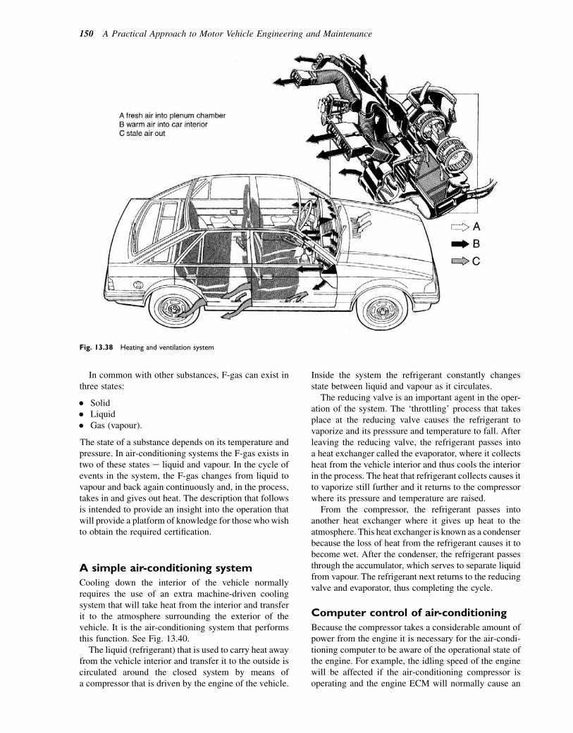
In common with other substances, F-gas can exist inthree states:
� Solid� Liquid� Gas (vapour).
The state of a substance depends on its temperature andpressure. In air-conditioning systems the F-gas exists intwo of these states e liquid and vapour. In the cycle ofevents in the system, the F-gas changes from liquid tovapour and back again continuously and, in the process,takes in and gives out heat. The description that followsis intended to provide an insight into the operation thatwill provide a platform of knowledge for those whowishto obtain the required certification.
A simple air-conditioning system
Cooling down the interior of the vehicle normallyrequires the use of an extra machine-driven coolingsystem that will take heat from the interior and transferit to the atmosphere surrounding the exterior of thevehicle. It is the air-conditioning system that performsthis function. See Fig. 13.40.
The liquid (refrigerant) that is used to carry heat awayfrom the vehicle interior and transfer it to the outside iscirculated around the closed system by means ofa compressor that is driven by the engine of the vehicle.
Inside the system the refrigerant constantly changesstate between liquid and vapour as it circulates.
The reducing valve is an important agent in the oper-ation of the system. The ‘throttling’ process that takesplace at the reducing valve causes the refrigerant tovaporize and its presssure and temperature to fall. Afterleaving the reducing valve, the refrigerant passes intoa heat exchanger called the evaporator, where it collectsheat from the vehicle interior and thus cools the interiorin the process. The heat that refrigerant collects causes itto vaporize still further and it returns to the compressorwhere its pressure and temperature are raised.
From the compressor, the refrigerant passes intoanother heat exchanger where it gives up heat to theatmosphere. This heat exchanger is known as a condenserbecause the loss of heat from the refrigerant causes it tobecome wet. After the condenser, the refrigerant passesthrough the accumulator, which serves to separate liquidfrom vapour. The refrigerant next returns to the reducingvalve and evaporator, thus completing the cycle.
Computer control of air-conditioning
Because the compressor takes a considerable amount ofpower from the engine it is necessary for the air-condi-tioning computer to be aware of the operational state ofthe engine. For example, the idling speed of the enginewill be affected if the air-conditioning compressor isoperating and the engine ECM will normally cause an
Fig. 13.38 Heating and ventilation system
150 A Practical Approach to Motor Vehicle Engineering and Maintenance
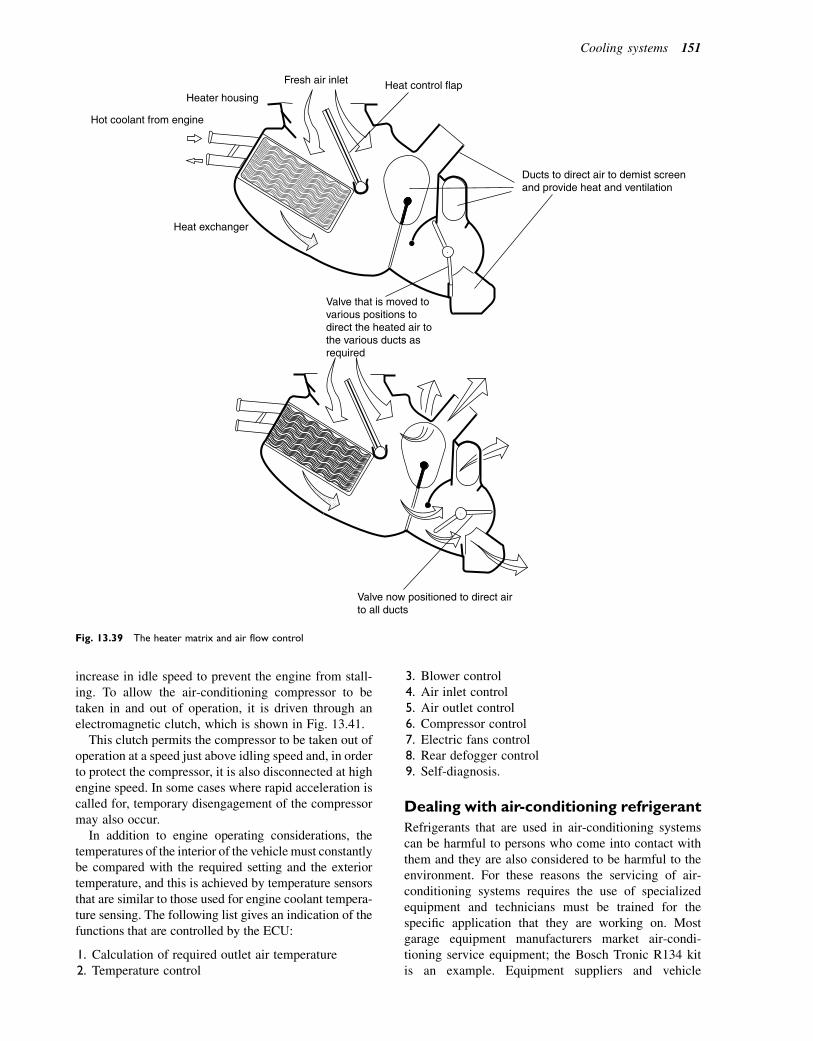
increase in idle speed to prevent the engine from stall-ing. To allow the air-conditioning compressor to betaken in and out of operation, it is driven through anelectromagnetic clutch, which is shown in Fig. 13.41.
This clutch permits the compressor to be taken out ofoperation at a speed just above idling speed and, in orderto protect the compressor, it is also disconnected at highengine speed. In some cases where rapid acceleration iscalled for, temporary disengagement of the compressormay also occur.
In addition to engine operating considerations, thetemperatures of the interior of the vehicle must constantlybe compared with the required setting and the exteriortemperature, and this is achieved by temperature sensorsthat are similar to those used for engine coolant tempera-ture sensing. The following list gives an indication of thefunctions that are controlled by the ECU:
1. Calculation of required outlet air temperature2. Temperature control
3. Blower control4. Air inlet control5. Air outlet control6. Compressor control7. Electric fans control8. Rear defogger control9. Self-diagnosis.
Dealing with air-conditioning refrigerant
Refrigerants that are used in air-conditioning systemscan be harmful to persons who come into contact withthem and they are also considered to be harmful to theenvironment. For these reasons the servicing of air-conditioning systems requires the use of specializedequipment and technicians must be trained for thespecific application that they are working on. Mostgarage equipment manufacturers market air-condi-tioning service equipment; the Bosch Tronic R134 kitis an example. Equipment suppliers and vehicle
Heat exchanger
Hot coolant from engine
Heater housing
Fresh air inlet Heat control flap
Ducts to direct air to demist screenand provide heat and ventilation
Valve that is moved tovarious positions todirect the heated air tothe various ducts asrequired
Valve now positioned to direct airto all ducts
Fig. 13.39 The heater matrix and air flow control
Cooling systems 151
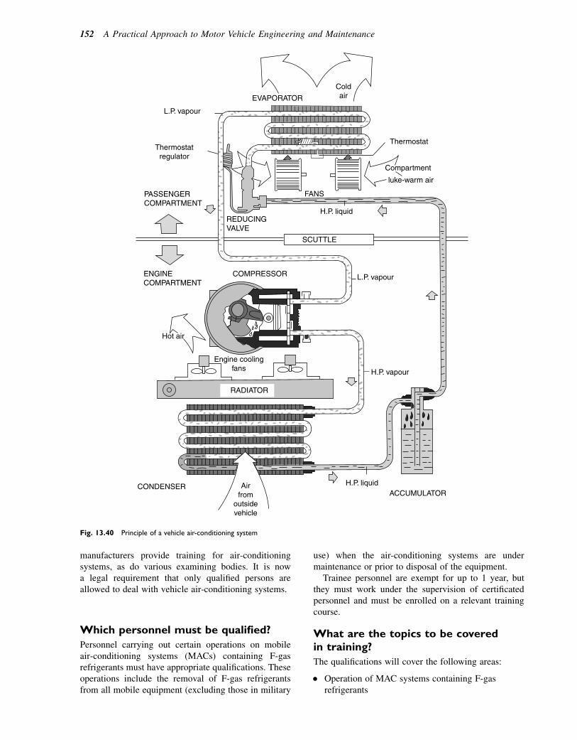
manufacturers provide training for air-conditioningsystems, as do various examining bodies. It is nowa legal requirement that only qualified persons areallowed to deal with vehicle air-conditioning systems.
Which personnel must be qualified?
Personnel carrying out certain operations on mobileair-conditioning systems (MACs) containing F-gasrefrigerants must have appropriate qualifications. Theseoperations include the removal of F-gas refrigerantsfrom all mobile equipment (excluding those in military
use) when the air-conditioning systems are undermaintenance or prior to disposal of the equipment.
Trainee personnel are exempt for up to 1 year, butthey must work under the supervision of certificatedpersonnel and must be enrolled on a relevant trainingcourse.
What are the topics to be coveredin training?
The qualifications will cover the following areas:
� Operation of MAC systems containing F-gasrefrigerants
ColdairEVAPORATOR
L.P. vapour
Thermostatregulator
PASSENGERCOMPARTMENT
REDUCINGVALVE
FANS
H.P. liquid
SCUTTLE
Thermostat
Compartment
L.P. vapour
Hot air
Engine coolingfans
COMPRESSORENGINECOMPARTMENT
H.P. vapour
H.P. liquidACCUMULATOR
Airfrom
outsidevehicle
CONDENSER
RADIATOR
luke-warm air
Fig. 13.40 Principle of a vehicle air-conditioning system
152 A Practical Approach to Motor Vehicle Engineering and Maintenance
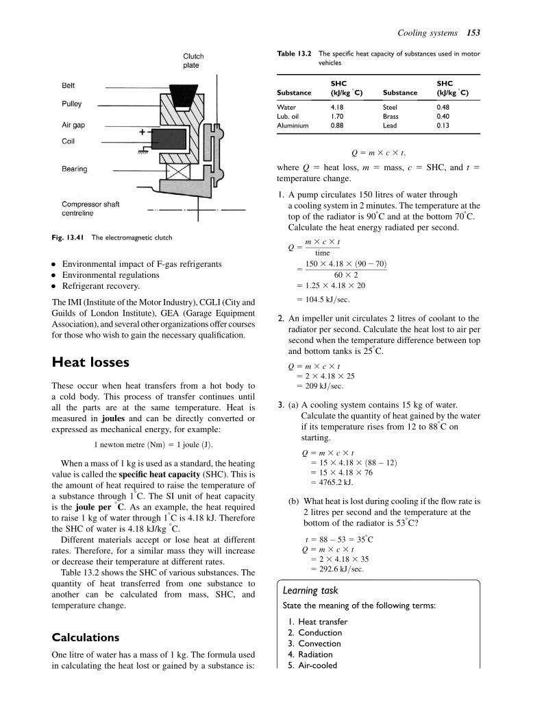
� Environmental impact of F-gas refrigerants� Environmental regulations� Refrigerant recovery.
The IMI (Institute of theMotor Industry), CGLI (City andGuilds of London Institute), GEA (Garage EquipmentAssociation), and several other organizations offer coursesfor those who wish to gain the necessary qualification.
Heat losses
These occur when heat transfers from a hot body toa cold body. This process of transfer continues untilall the parts are at the same temperature. Heat ismeasured in joules and can be directly converted orexpressed as mechanical energy, for example:
1 newton metre ðNmÞ 5 1 joule ðJÞ:
When a mass of 1 kg is used as a standard, the heatingvalue is called the specific heat capacity (SHC). This isthe amount of heat required to raise the temperature ofa substance through 18C. The SI unit of heat capacityis the joule per 8C. As an example, the heat requiredto raise 1 kg of water through 18C is 4.18 kJ. Thereforethe SHC of water is 4.18 kJ/kg 8C.
Different materials accept or lose heat at differentrates. Therefore, for a similar mass they will increaseor decrease their temperature at different rates.
Table 13.2 shows the SHC of various substances. Thequantity of heat transferred from one substance toanother can be calculated from mass, SHC, andtemperature change.
Calculations
One litre of water has a mass of 1 kg. The formula usedin calculating the heat lost or gained by a substance is:
Q 5 m 3 c 3 t;
where Q 5 heat loss, m 5 mass, c 5 SHC, and t 5temperature change.
1. A pump circulates 150 litres of water througha cooling system in 2 minutes. The temperature at thetop of the radiator is 908C and at the bottom 708C.Calculate the heat energy radiated per second.
Q 5m 3 c 3 t
time
5150 3 4:18 3 ð902 70Þ
60 3 2
5 1:25 3 4:18 3 20
5 104:5 kJ=sec:
2. An impeller unit circulates 2 litres of coolant to theradiator per second. Calculate the heat lost to air persecond when the temperature difference between topand bottom tanks is 258C.
Q 5 m 3 c 3 t5 2 3 4:18 3 255 209 kJ=sec:
3. (a) A cooling system contains 15 kg of water.Calculate the quantity of heat gained by the waterif its temperature rises from 12 to 888C onstarting.
Q 5 m 3 c 3 t5 15 3 4:18 3 ð88� 12Þ5 15 3 4:18 3 765 4765:2 kJ:
(b) What heat is lost during cooling if the flow rate is2 litres per second and the temperature at thebottom of the radiator is 538C?
t 5 88� 53 5 358CQ 5 m 3 c 3 t
5 2 3 4:18 3 355 292:6 kJ=sec:
Learning task
State the meaning of the following terms:
1. Heat transfer2. Conduction3. Convection4. Radiation5. Air-cooled
Table 13.2 The specific heat capacity of substances used in motor
vehicles
Substance
SHC
(kJ/kg 8C) Substance
SHC
(kJ/kg 8C)
Water 4.18 Steel 0.48
Lub. oil 1.70 Brass 0.40
Aluminium 0.88 Lead 0.13
Fig. 13.41 The electromagnetic clutch
Cooling systems 153
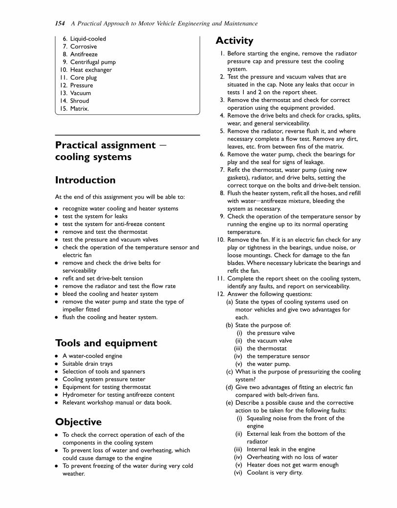
6. Liquid-cooled7. Corrosive8. Antifreeze9. Centrifugal pump
10. Heat exchanger11. Core plug12. Pressure13. Vacuum14. Shroud15. Matrix.
Practical assignment ecooling systems
Introduction
At the end of this assignment you will be able to:
� recognize water cooling and heater systems� test the system for leaks� test the system for anti-freeze content� remove and test the thermostat� test the pressure and vacuum valves� check the operation of the temperature sensor and
electric fan� remove and check the drive belts for
serviceability� refit and set drive-belt tension� remove the radiator and test the flow rate� bleed the cooling and heater system� remove the water pump and state the type of
impeller fitted� flush the cooling and heater system.
Tools and equipment� A water-cooled engine� Suitable drain trays� Selection of tools and spanners� Cooling system pressure tester� Equipment for testing thermostat� Hydrometer for testing antifreeze content� Relevant workshop manual or data book.
Objective� To check the correct operation of each of the
components in the cooling system� To prevent loss of water and overheating, which
could cause damage to the engine� To prevent freezing of the water during very cold
weather.
Activity1. Before starting the engine, remove the radiator
pressure cap and pressure test the coolingsystem.
2. Test the pressure and vacuum valves that aresituated in the cap. Note any leaks that occur intests 1 and 2 on the report sheet.
3. Remove the thermostat and check for correctoperation using the equipment provided.
4. Remove the drive belts and check for cracks, splits,wear, and general serviceability.
5. Remove the radiator, reverse flush it, and wherenecessary complete a flow test. Remove any dirt,leaves, etc. from between fins of the matrix.
6. Remove the water pump, check the bearings forplay and the seal for signs of leakage.
7. Refit the thermostat, water pump (using newgaskets), radiator, and drive belts, setting thecorrect torque on the bolts and drive-belt tension.
8. Flush the heater system, refit all the hoses, and refillwith watereantifreeze mixture, bleeding thesystem as necessary.
9. Check the operation of the temperature sensor byrunning the engine up to its normal operatingtemperature.
10. Remove the fan. If it is an electric fan check for anyplay or tightness in the bearings, undue noise, orloose mountings. Check for damage to the fanblades. Where necessary lubricate the bearings andrefit the fan.
11. Complete the report sheet on the cooling system,identify any faults, and report on serviceability.
12. Answer the following questions:(a) State the types of cooling systems used on
motor vehicles and give two advantages foreach.
(b) State the purpose of:(i) the pressure valve(ii) the vacuum valve(iii) the thermostat(iv) the temperature sensor(v) the water pump.
(c) What is the purpose of pressurizing the coolingsystem?
(d) Give two advantages of fitting an electric fancompared with belt-driven fans.
(e) Describe a possible cause and the correctiveaction to be taken for the following faults:(i) Squealing noise from the front of the
engine(ii) External leak from the bottom of the
radiator(iii) Internal leak in the engine(iv) Overheating with no loss of water(v) Heater does not get warm enough(vi) Coolant is very dirty.
154 A Practical Approach to Motor Vehicle Engineering and Maintenance
Checklist
Visual checks on Vehicle
� Type of radiator fitted� Type of fan fitted� Type of cooling system.
Practical tests on the coolingsystem
� Antifreeze content� Pressure test of cap� Pressure test of system� Fan-belt tension and condition� Operation of heater� Operation of fan� Operation of thermostat� Radiator flow test� Manufacturer’s technical data.
Comments on serviceability
Student’s signature
Supervisor’s signature
Practical assignment e liquidcooling systems
Objective
To carry out a number of tests on the cooling system toascertain its serviceability:
� Thermostat setting� System pressure testing� Radiator flow test.
Tools and equipment� Running engine/vehicle� Assorted hand tools� Thermostat testing equipment� Pressure tester� Header tank, drain tank, and fittings� Stopwatch.
Safety aspects� Cables, hands, hair, and loose clothing must be kept
clear of fans and other rotating parts. Stationaryengines require guards to be fitted to the fan drive.
� Keep hands clear of hot parts of the engine.
� If a vehicle is used, the gear lever must be inthe neutral position, the handbrake applied, andthe wheels chocked before operating the startermotor.
� Arrangements must be made for the exhaust gases topass directly out of any enclosed space.
� Remove radiator cap slowly and cover with a cloth ifthe engine is hot.
Safety questions1. Why must the exhaust gases not be discharged into
the garage?2. What are the dangers from unguarded fan blades and
fan belts?3. What is likely to happen if the radiator cap is
removed quickly when the engine is hot?
Activity1. (a) Disconnect hoses and housing and remove the
thermostat from the engine.(b) Place the thermostat in the tester and heat the
water to the opening temperature of thethermostat, watch for commencement ofopening and fully open point, note thetemperatures, and record the results.
Note
It may be necessary to first subject the thermostat toboiling water so that the fully open position can beassessed.
(c) The recommended opening temperaturesshould be obtained from the data book.
(d) Replace the thermostat in the correctposition, refit the housing using a newgasket as required, fit hoses and tightenhose clips, run engine and check for waterleaks.
2. (a) Remove radiator cap (observe safetyinstructions).
(b) Fit pressure testing equipment in place of theradiator cap, operate pump to pressurize systemto recommended pressure.
(c) Carry out visual inspection of componentsin the cooling system and joints for coolantleakage.
Note
Look for a steady reading of the pressure testergauge; if the pressure falls steadily and there is nocoolant leakage, then an internal leakage of thecoolant can be suspected. (Check that the tester unitis fully sealed on the radiator neck.)
Cooling systems 155
(d) To identify internal leakage there are productson the market that can be mixed with thecoolant, the system is closed and the engine isrun until it reaches its normal operatingtemperature. After the system cools theradiator cap is removed and the colour of thecoolant is inspected. The chemical changescolour when it comes into contact withoxygen. Therefore, if the colour of the coolantchanges it can be assumed that air is enteringthe system, most probably through thecylinder head gasket.
(e) The radiator cap can be checked for correctoperation by fitting the correct adaptor to thepump and fitting the cap in place on the tester.The pressure is then raised by operating thepump and recorded when the stage is reachedfor the seal and the spring in the cap to lift and sorelieve the pressure.
3. To flow test the radiator:(a) Remove the radiator and fit it to the test rig.(b) Fill the header tank of the rig with a known
quantity of water.(c) Open the tap to discharge the water through the
radiator and measure the draining time witha stopwatch. Compare this with themanufacturing data (20 litres takesapproximately 20 seconds for a car radiator witha water head of 0.7 metres).
(d) The mineral deposits in the coolant tend toblock the water ways, so an approximation ofthe flow rate can be ascertained by comparingthe mass of the radiator under test with themass of a new radiator of the same type. Thedeposits are heavy so a 25% increase in weightwill give an indication of several mineraldeposits.
Questions
1. What are the effects of pressurizing the coolingsystem?
2. Explain the function of the two valves in the pressurecap.
3. List five reasons for an engine becomingoverheated.
Self-assessment questions1. A thermostat is fitted to cooling systems:(a) to provide a variable current in the temperature
gauge circuit(b) to control circulation of coolant to
help the system to warm up quickly and
to maintain a constant operatingtemperature
(c) to act as a control to switch the cooling fan onand off
(d) to operate the compressor on an air-conditioning system.
2. The lubrication system of a certain enginecontains 0.8 kg of oil that has a specific heat capacityof 1.7 kJ/kg8C. During the warm-up period thetemperature of the oil rises by 308C. The amountof energy transferred to the oil during this warm-upperiod is:(a) 32.5 J(b) 325 MJ(c) 40.8 kJ(d) 408 J.
3. Inside a pressurized cooling system:(a) the coolant boiling temperature is
above 1008C(b) the increased pressure slows down the
circulation of coolant(c) the boiling point of the coolant is lowered(d) the convection currents cease to operate.
4. Ethylene-glycol-based antifreeze when added to thecoolant causes:(a) less evaporation of the coolant(b) the freezing temperature of the coolant to be
raised(c) the freezing temperature of the coolant to be
lowered(d) the boiling point temperature of the coolant to
be lowered.5. The purpose of the water pump in a cooling system
is to:(a) pressurize the cooling system(b) circulate the coolant(c) eliminate the need for a radiator(d) reduce heat loss.
6. After combustion the temperature inside theengine cylinder is:(a) approximately 2008C(b) approximately 12 0008C(c) approximately 1400e20008C(d) 2508C.
7. Cooling systems rely on heat transfer by:(a) pressure differentiation(b) electrical conductivity(c) Archimedes’ principle(d) conduction, convection, and radiation.
8. Radiator surfaces are often finished in matt blackbecause:(a) this surface is effective against corrosion(b) this surface is most effective in radiating
heat(c) this type of finish reflects most heat(d) this surface finish prevents heat escaping into
the atmosphere.
156 A Practical Approach to Motor Vehicle Engineering and Maintenance

9. What feature of the electric cooling fan systemassists the engine to reach its normal workingtemperature more quickly than the belt-driven typeof fan?
10. If an electric fan operates at 300 W in a12-volt system, the current drawn in the pumpcircuit is:
(a) 25 amperes(b) 2.5 amperes(c) 0.25 amperes(d) 250 amperes.
11. What minimum fuse rating would be suitable forthe electric fan circuit?
Cooling systems 157
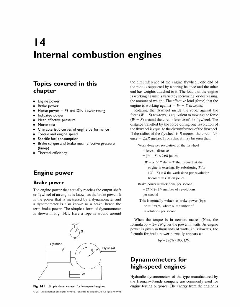
14Internal combustion engines
Topics covered in thischapter
� Engine power� Brake power� Horse power e PS and DIN power rating� Indicated power� Mean effective pressure� Morse test� Characteristic curves of engine performance� Torque and engine speed� Specific fuel consumption� Brake torque and brake mean effective pressure
(bmep)� Thermal efficiency.
Engine power
Brake power
The engine power that actually reaches the output shaftor flywheel of an engine is known as the brake power. Itis the power that is measured by a dynamometer anda dynamometer is also known as a brake, hence theterm brake power. The simplest form of dynamometeris shown in Fig. 14.1. Here a rope is wound around
the circumference of the engine flywheel; one end ofthe rope is supported by a spring balance and the otherend has weights attached to it. The load that the engineis working against is varied by increasing, or decreasing,the amount of weight. The effective load (force) that theengine is working against 5 W 2 S newtons.
Rotating the flywheel inside the rope, against theforce (W2 S) newtons, is equivalent to moving the force(W 2 S) around the circumference of the flywheel. Thedistance travelled by the force during one revolution ofthe flywheel is equal to the circumference of the flywheel.If the radius of the flywheel is R metres, the circumfer-ence 5 2pR metres. From this, it may be seen that:
Work done per revolution of the flywheel
5 force3 distance
5 ðW � SÞ3 2pR joules
ðW � SÞ3R also5 T; the torque that the
engine is exerting: By substituting T for
ðW � SÞ3R the work done per revolution
becomes5 T 3 2p joules
Brake power5work done per second
5 ðT3 2pÞ3 number of revolutions
per second
This is normally written as brake power ðbpÞ:bp5 2pTN; where N5 number of
revolutions per second:
When the torque is in newton metres (Nm), theformula bp5 2p TN gives the power in watts. As enginepower is given in thousands of watts, i.e. kilowatts, theformula for brake power normally appears as:
bp5 2pTN=1000 kW:
Dynamometers forhigh-speed engines
Hydraulic dynamometers of the type manufactured bythe HeenaneFroude company are commonly used forengine testing purposes. The energy from the engine is
R
W
S
FlywheelCylinder
Fig. 14.1 Simple dynamometer for low-speed engines
� 2011 Allan Bonnick and Derek Newbold. Published by Elsevier Ltd. All rights reserved
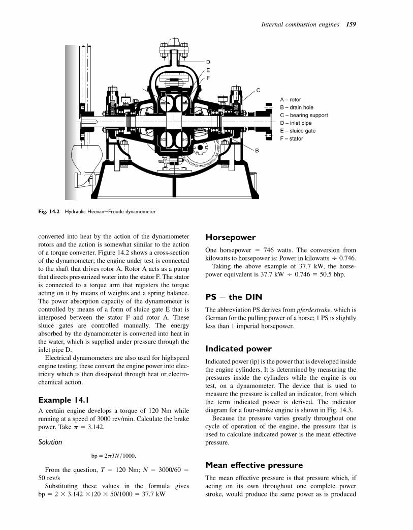
converted into heat by the action of the dynamometerrotors and the action is somewhat similar to the actionof a torque converter. Figure 14.2 shows a cross-sectionof the dynamometer; the engine under test is connectedto the shaft that drives rotor A. Rotor A acts as a pumpthat directs pressurized water into the stator F. The statoris connected to a torque arm that registers the torqueacting on it by means of weights and a spring balance.The power absorption capacity of the dynamometer iscontrolled by means of a form of sluice gate E that isinterposed between the stator F and rotor A. Thesesluice gates are controlled manually. The energyabsorbed by the dynamometer is converted into heat inthe water, which is supplied under pressure through theinlet pipe D.
Electrical dynamometers are also used for highspeedengine testing; these convert the engine power into elec-tricity which is then dissipated through heat or electro-chemical action.
Example 14.1
A certain engine develops a torque of 120 Nm whilerunning at a speed of 3000 rev/min. Calculate the brakepower. Take p 5 3.142.
Solution
bp5 2pTN=1000:
From the question, T 5 120 Nm; N 5 3000/60 550 rev/s
Substituting these values in the formula givesbp 5 2 3 3.142 3120 3 50/1000 5 37.7 kW
Horsepower
One horsepower 5 746 watts. The conversion fromkilowatts to horsepower is: Power in kilowattsO 0.746.
Taking the above example of 37.7 kW, the horse-power equivalent is 37.7 kW O 0.746 5 50.5 bhp.
PS e the DIN
The abbreviation PS derives from pferdestrake, which isGerman for the pulling power of a horse; 1 PS is slightlyless than 1 imperial horsepower.
Indicated power
Indicated power (ip) is the power that is developed insidethe engine cylinders. It is determined by measuring thepressures inside the cylinders while the engine is ontest, on a dynamometer. The device that is used tomeasure the pressure is called an indicator, from whichthe term indicated power is derived. The indicatordiagram for a four-stroke engine is shown in Fig. 14.3.
Because the pressure varies greatly throughout onecycle of operation of the engine, the pressure that isused to calculate indicated power is the mean effectivepressure.
Mean effective pressure
The mean effective pressure is that pressure which, ifacting on its own throughout one complete powerstroke, would produce the same power as is produced
A – rotorB – drain holeC – bearing support D – inlet pipeE – sluice gateF – stator
D
E
F
C
B
Fig. 14.2 Hydraulic HeenaneFroude dynamometer
Internal combustion engines 159
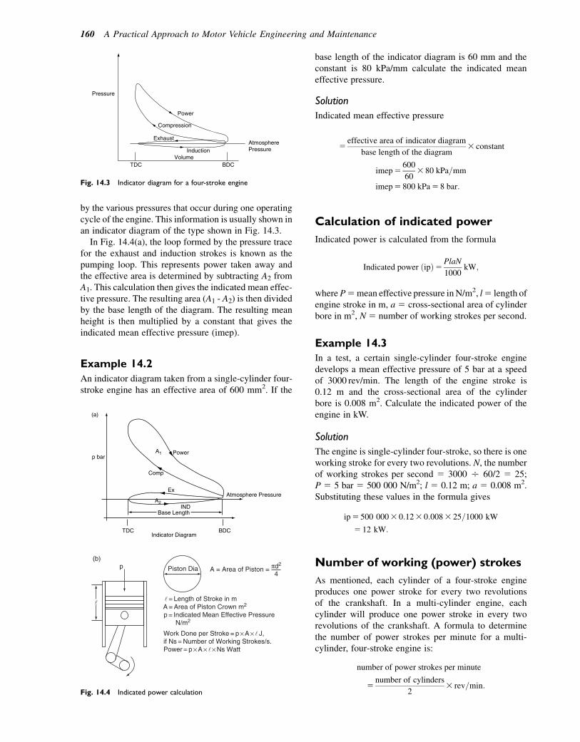
by the various pressures that occur during one operatingcycle of the engine. This information is usually shown inan indicator diagram of the type shown in Fig. 14.3.
In Fig. 14.4(a), the loop formed by the pressure tracefor the exhaust and induction strokes is known as thepumping loop. This represents power taken away andthe effective area is determined by subtracting A2 fromA1. This calculation then gives the indicated mean effec-tive pressure. The resulting area (A1 - A2) is then dividedby the base length of the diagram. The resulting meanheight is then multiplied by a constant that gives theindicated mean effective pressure (imep).
Example 14.2
An indicator diagram taken from a single-cylinder four-stroke engine has an effective area of 600 mm2. If the
base length of the indicator diagram is 60 mm and theconstant is 80 kPa/mm calculate the indicated meaneffective pressure.
Solution
Indicated mean effective pressure
5effective area of indicator diagram
base length of the diagram3 constant
imep5600
603 80 kPa=mm
imep5 800 kPa5 8 bar:
Calculation of indicated power
Indicated power is calculated from the formula
Indicated power ðipÞ5PlaN
1000kW;
whereP5mean effective pressure inN/m2, l5 length ofengine stroke in m, a 5 cross-sectional area of cylinderbore in m2, N 5 number of working strokes per second.
Example 14.3
In a test, a certain single-cylinder four-stroke enginedevelops a mean effective pressure of 5 bar at a speedof 3000 rev/min. The length of the engine stroke is0.12 m and the cross-sectional area of the cylinderbore is 0.008 m2. Calculate the indicated power of theengine in kW.
Solution
The engine is single-cylinder four-stroke, so there is oneworking stroke for every two revolutions. N, the numberof working strokes per second 5 3000 O 60/2 5 25;P 5 5 bar 5 500 000 N/m2; l 5 0.12 m; a 5 0.008 m2.Substituting these values in the formula gives
ip5 500 0003 0:123 0:0083 25=1000 kW
5 12 kW:
Number of working (power) strokes
As mentioned, each cylinder of a four-stroke engineproduces one power stroke for every two revolutionsof the crankshaft. In a multi-cylinder engine, eachcylinder will produce one power stroke in every tworevolutions of the crankshaft. A formula to determinethe number of power strokes per minute for a multi-cylinder, four-stroke engine is:
number of power strokes per minute
5number of cylinders
23 rev=min:
Power
Pressure
Exhaust
Induction Atmosphere Pressure
Volume BDC TDC
Compression
Fig. 14.3 Indicator diagram for a four-stroke engine
Power
Comp
Ex
INDBase Length
p barA1
A2
Atmosphere Pressure
Indicator Diagram
(a)
BDCTDC
(b)p Piston Dia A = Area of Piston = d2
4
= Length of Stroke in mA = Area of Piston Crown m2
p = Indicated Mean Effective PressureN/m2
Work Done per Stroke = p A J,if Ns = Number of Working Strokes/s.Power = p A Ns Watt
Fig. 14.4 Indicated power calculation
160 A Practical Approach to Motor Vehicle Engineering and Maintenance
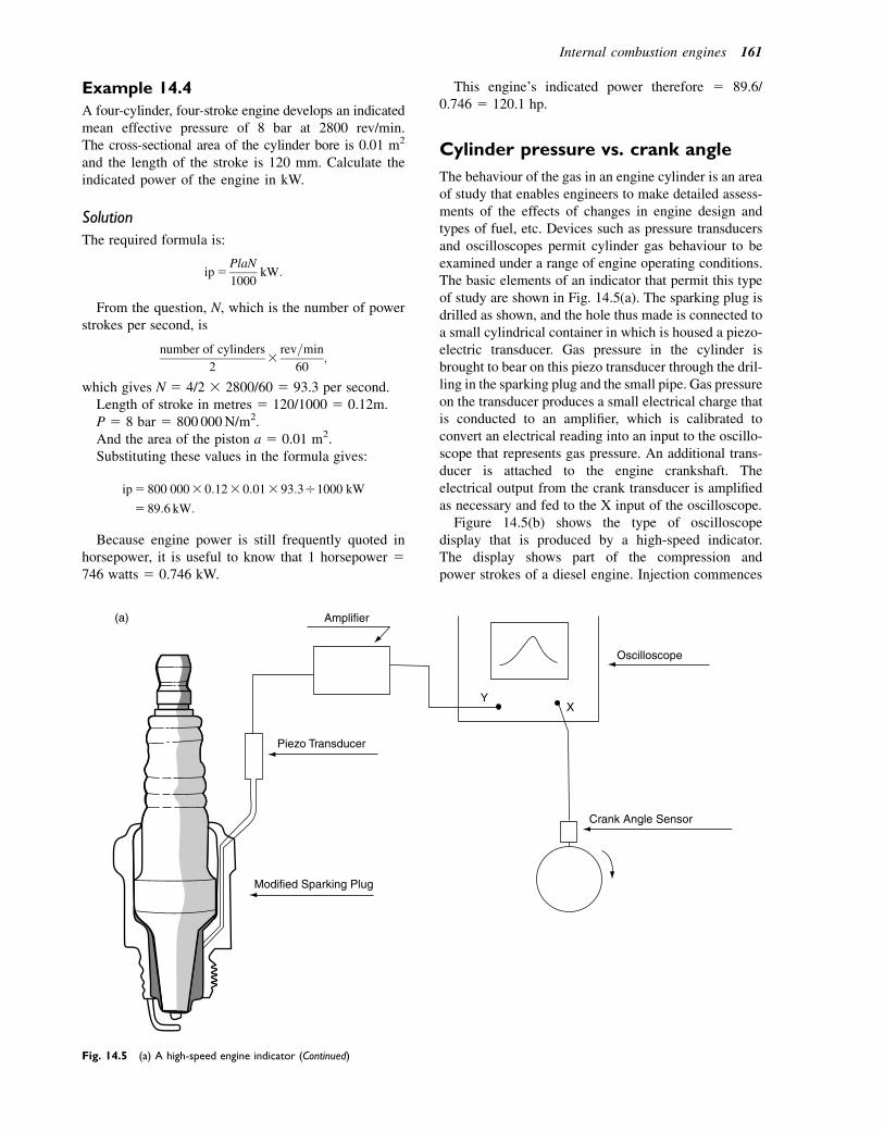
Example 14.4
A four-cylinder, four-stroke engine develops an indicatedmean effective pressure of 8 bar at 2800 rev/min.The cross-sectional area of the cylinder bore is 0.01 m2
and the length of the stroke is 120 mm. Calculate theindicated power of the engine in kW.
Solution
The required formula is:
ip5PlaN
1000kW:
From the question, N, which is the number of powerstrokes per second, is
number of cylinders
23
rev=min
60;
which gives N 5 4/2 3 2800/60 5 93.3 per second.Length of stroke in metres 5 120/1000 5 0.12m.P 5 8 bar 5 800 000N/m2.And the area of the piston a 5 0.01 m2.Substituting these values in the formula gives:
ip5 800 0003 0:123 0:013 93:3O1000 kW
5 89:6 kW:
Because engine power is still frequently quoted inhorsepower, it is useful to know that 1 horsepower 5746 watts 5 0.746 kW.
This engine’s indicated power therefore 5 89.6/0.746 5 120.1 hp.
Cylinder pressure vs. crank angle
The behaviour of the gas in an engine cylinder is an areaof study that enables engineers to make detailed assess-ments of the effects of changes in engine design andtypes of fuel, etc. Devices such as pressure transducersand oscilloscopes permit cylinder gas behaviour to beexamined under a range of engine operating conditions.The basic elements of an indicator that permit this typeof study are shown in Fig. 14.5(a). The sparking plug isdrilled as shown, and the hole thus made is connected toa small cylindrical container in which is housed a piezo-electric transducer. Gas pressure in the cylinder isbrought to bear on this piezo transducer through the dril-ling in the sparking plug and the small pipe. Gas pressureon the transducer produces a small electrical charge thatis conducted to an amplifier, which is calibrated toconvert an electrical reading into an input to the oscillo-scope that represents gas pressure. An additional trans-ducer is attached to the engine crankshaft. Theelectrical output from the crank transducer is amplifiedas necessary and fed to the X input of the oscilloscope.
Figure 14.5(b) shows the type of oscilloscopedisplay that is produced by a high-speed indicator.The display shows part of the compression andpower strokes of a diesel engine. Injection commences
(a)
Modified Sparking Plug
Piezo Transducer
Amplifier
Y X
Oscilloscope
Crank Angle Sensor
Fig. 14.5 (a) A high-speed engine indicator (Continued)
Internal combustion engines 161
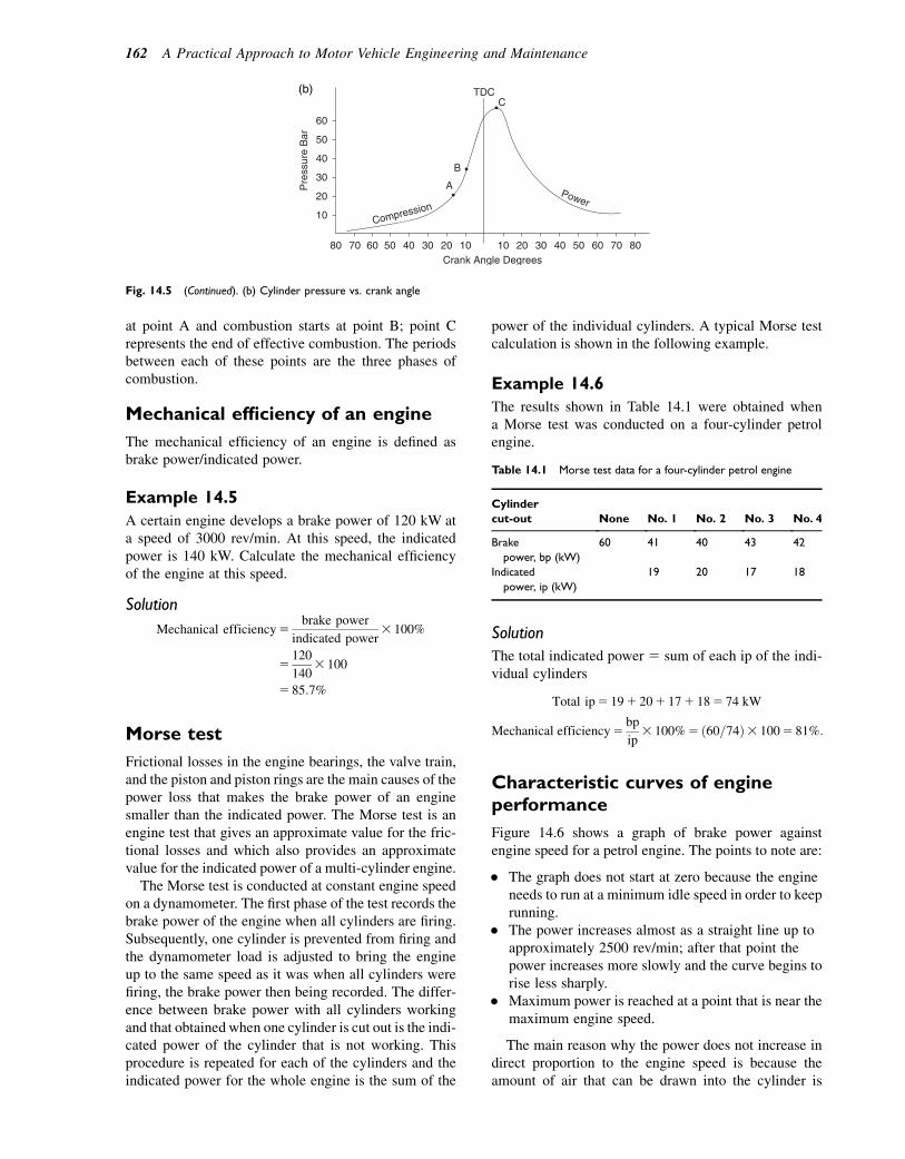
at point A and combustion starts at point B; point Crepresents the end of effective combustion. The periodsbetween each of these points are the three phases ofcombustion.
Mechanical efficiency of an engine
The mechanical efficiency of an engine is defined asbrake power/indicated power.
Example 14.5
A certain engine develops a brake power of 120 kW ata speed of 3000 rev/min. At this speed, the indicatedpower is 140 kW. Calculate the mechanical efficiencyof the engine at this speed.
Solution
Mechanical efficiency5brake power
indicated power3 100%
5120
1403 100
5 85:7%
Morse test
Frictional losses in the engine bearings, the valve train,and the piston and piston rings are the main causes of thepower loss that makes the brake power of an enginesmaller than the indicated power. The Morse test is anengine test that gives an approximate value for the fric-tional losses and which also provides an approximatevalue for the indicated power of a multi-cylinder engine.
The Morse test is conducted at constant engine speedon a dynamometer. The first phase of the test records thebrake power of the engine when all cylinders are firing.Subsequently, one cylinder is prevented from firing andthe dynamometer load is adjusted to bring the engineup to the same speed as it was when all cylinders werefiring, the brake power then being recorded. The differ-ence between brake power with all cylinders workingand that obtained when one cylinder is cut out is the indi-cated power of the cylinder that is not working. Thisprocedure is repeated for each of the cylinders and theindicated power for the whole engine is the sum of the
power of the individual cylinders. A typical Morse testcalculation is shown in the following example.
Example 14.6
The results shown in Table 14.1 were obtained whena Morse test was conducted on a four-cylinder petrolengine.
Solution
The total indicated power 5 sum of each ip of the indi-vidual cylinders
Total ip5 191 201 171 185 74 kW
Mechanical efficiency5bp
ip3 100%5 ð60=74Þ3 1005 81%:
Characteristic curves of engineperformance
Figure 14.6 shows a graph of brake power againstengine speed for a petrol engine. The points to note are:
� The graph does not start at zero because the engineneeds to run at a minimum idle speed in order to keeprunning.
� The power increases almost as a straight line up toapproximately 2500 rev/min; after that point thepower increases more slowly and the curve begins torise less sharply.
� Maximum power is reached at a point that is near themaximum engine speed.
The main reason why the power does not increase indirect proportion to the engine speed is because theamount of air that can be drawn into the cylinder is
60
50
40
30
20
10
80 70 60 50 40 30 20 10 10 20 30 40 50 60 70 80
Pre
ssur
e B
ar
Compression
B
A
TDC C
Power
Crank Angle Degrees
(b)
Fig. 14.5 (Continued). (b) Cylinder pressure vs. crank angle
Table 14.1 Morse test data for a four-cylinder petrol engine
Cylinder
cut-out None No. 1 No. 2 No. 3 No. 4
Brake
power, bp (kW)
60 41 40 43 42
Indicated
power, ip (kW)
19 20 17 18
162 A Practical Approach to Motor Vehicle Engineering and Maintenance
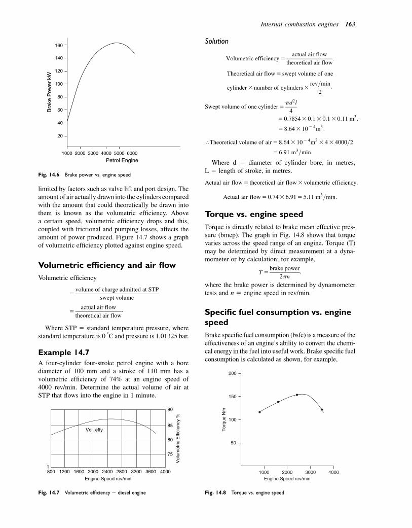
limited by factors such as valve lift and port design. Theamount of air actually drawn into the cylinders comparedwith the amount that could theoretically be drawn intothem is known as the volumetric efficiency. Abovea certain speed, volumetric efficiency drops and this,coupled with frictional and pumping losses, affects theamount of power produced. Figure 14.7 shows a graphof volumetric efficiency plotted against engine speed.
Volumetric efficiency and air flow
Volumetric efficiency
5volume of charge admitted at STP
swept volume
5actual air flow
theoretical air flow:
Where STP 5 standard temperature pressure, wherestandard temperature is 0 8C and pressure is 1.01325 bar.
Example 14.7
A four-cylinder four-stroke petrol engine with a borediameter of 100 mm and a stroke of 110 mm has avolumetric efficiency of 74% at an engine speed of4000 rev/min. Determine the actual volume of air atSTP that flows into the engine in 1 minute.
Solution
Volumetric efficiency5actual air flow
theoretical air flow:
Theoretical air flow5 swept volume of one
cylinder3 number of cylinders3rev=min
2:
Swept volume of one cylinder5pd2l
4
5 0:78543 0:13 0:13 0:11 m3:
5 8:643 102 4m3:
rTheoretical volume of air5 8:643 102 4m33 43 4000=2
5 6:91 m3=min:
Where d 5 diameter of cylinder bore, in metres,L 5 length of stroke, in metres.
Actual air flow5 theoretical air flow3 volumetric efficiency:
Actual air flow5 0:743 6:915 5:11 m3=min:
Torque vs. engine speed
Torque is directly related to brake mean effective pres-sure (bmep). The graph in Fig. 14.8 shows that torquevaries across the speed range of an engine. Torque (T)may be determined by direct measurement at a dyna-mometer or by calculation; for example,
T 5brake power
2pn;
where the brake power is determined by dynamometertests and n 5 engine speed in rev/min.
Specific fuel consumption vs. enginespeed
Brake specific fuel consumption (bsfc) is a measure of theeffectiveness of an engine’s ability to convert the chemi-cal energy in the fuel into useful work. Brake specific fuelconsumption is calculated as shown, for example,
1000
20
40
2000 3000
Petrol Engine
Bra
ke P
ower
kW
4000 5000 6000
60
80
100
120
140
160
Fig. 14.6 Brake power vs. engine speed
8001
1200 1600 2000
Engine Speed rev/min
Vol. effy
Vol
umet
ric E
ffici
ency
%
2400 2800 3200 3600 4000
75
80
85
90
Fig. 14.7 Volumetric efficiency e diesel engine
1000
50
100
150
200
Engine Speed rev/min
Tor
que
Nm
2000 3000 4000
Fig. 14.8 Torque vs. engine speed
Internal combustion engines 163

bsfc5mass of fuel consumed per hour
brake power:
Figure 14.9 shows how bsfc varies with engine speed.
Example 14.8
The results shown in Table 14.2 were obtained duringa fuel consumption test on an engine.
Determine the specific fuel consumption (sfc) inkg/kWh in each case and plot a graph of specificfuel consumption on a base of brake power.
Solution
Specific fuel consumption:
sfc5mass of fuel used per hour
brake power:
Results are shown in Table 14.3.
Brake power, torque, and sfccompared
In order to assess the importance of these curves, it isnormal practice to plot brake power, torque, and specific
fuel consumption on a common base of engine speed.The vertical scales are made appropriate to each vari-able. Figure 14.10 shows such a graph.
The points to note are:
� the maximum power of 52 kW occurs at4000 rev/min;
� the minimum specific fuel consumption of237 g/kWh occurs at 2000 rev/min;
� the maximum torque of 147 Nm occurs at2100 rev/min.
This data highlights details that affect vehicle behav-iour; e.g. when the specific fuel consumption is at itslowest value the engine is consuming the least possibleamount of fuel for the given conditions e this is consid-ered to be the most economical operating speed of theengine. The maximum torque also occurs at approxi-mately the same speed, because torque converts to trac-tive effort; the maximum tractive effort is obtained at thesame engine speed as is found for the maximum torquespeed.
Themaximum power is reached at a high engine speed.The ratio of maximum power speed to maximum tor-
que speed is known as the engine speed ratio.The most useful part of the power curve of the engine
lies between the maximum power speed and themaximum torque speed. The difference betweenmaximum power speed and maximum torque speed isknown as the engine operating range.
In this case the engine operating speed range 54000 rev/min e 2100 rev/min 5 1900 rev/min.
The actual shapes of the graphs of these engine char-acteristics are determined by engine design. The graphsfor a heavy transport vehicle engine may be expected tobe quite different from those for a saloon car.
Table 14.2 Results of fuel consumption test on an engine
Brake power (kW) 10 15 20 25 30 35
Total fuel consumed
per hour (kg)
4 5.21 6.74 8.4 10.59 12.6
1000
100
200
300
400
Engine Speed rev/min 2000 3000 4000
Spe
cific
Fue
l Con
sum
ptio
n g/
kWh
Fig. 14.9 Specific fuel consumption vs. engine speed
160 150
140
130
120
110
100
310
290
270
250
230
1000
10
20
30
40
50
2000
r/min 3000 4000
210
Tor
que
Nm
s.
f.c
g/kw
h
Pow
er
kW
Fig. 14.10 Characteristic curves of diesel engine variables
Table 14.3 Specific fuel consumption calculations based on Table
14.2 (Example 14.8)
Brake power
(kW)
10 15 20 25 30 35
Specific fuel
consumption
(kg/kWh)
0.4 0.347 0.337 0.336 0.353 0.36
164 A Practical Approach to Motor Vehicle Engineering and Maintenance
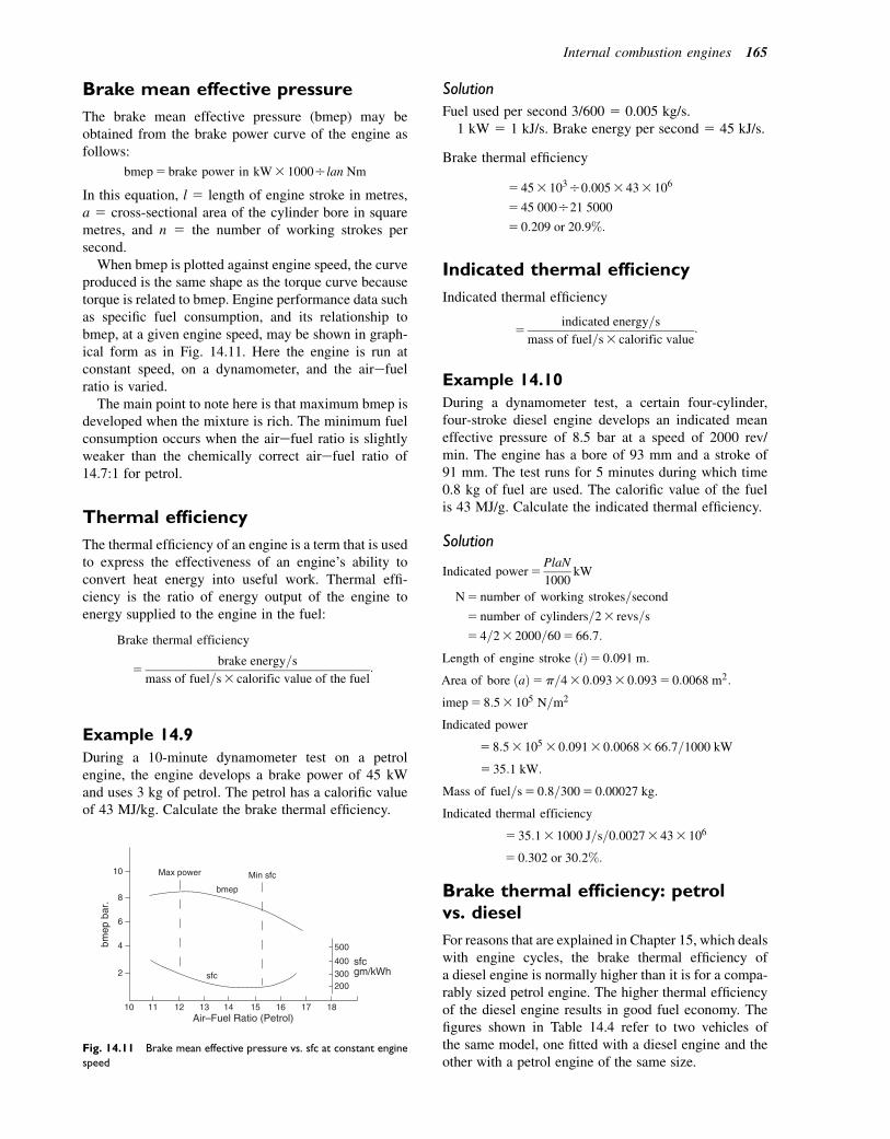
Brake mean effective pressure
The brake mean effective pressure (bmep) may beobtained from the brake power curve of the engine asfollows:
bmep5 brake power in kW3 1000Olan Nm
In this equation, l 5 length of engine stroke in metres,a 5 cross-sectional area of the cylinder bore in squaremetres, and n 5 the number of working strokes persecond.
When bmep is plotted against engine speed, the curveproduced is the same shape as the torque curve becausetorque is related to bmep. Engine performance data suchas specific fuel consumption, and its relationship tobmep, at a given engine speed, may be shown in graph-ical form as in Fig. 14.11. Here the engine is run atconstant speed, on a dynamometer, and the airefuelratio is varied.
The main point to note here is that maximum bmep isdeveloped when the mixture is rich. The minimum fuelconsumption occurs when the airefuel ratio is slightlyweaker than the chemically correct airefuel ratio of14.7:1 for petrol.
Thermal efficiency
The thermal efficiency of an engine is a term that is usedto express the effectiveness of an engine’s ability toconvert heat energy into useful work. Thermal effi-ciency is the ratio of energy output of the engine toenergy supplied to the engine in the fuel:
Brake thermal efficiency
5brake energy=s
mass of fuel=s3 calorific value of the fuel:
Example 14.9
During a 10-minute dynamometer test on a petrolengine, the engine develops a brake power of 45 kWand uses 3 kg of petrol. The petrol has a calorific valueof 43 MJ/kg. Calculate the brake thermal efficiency.
Solution
Fuel used per second 3/600 5 0.005 kg/s.1 kW 5 1 kJ/s. Brake energy per second 5 45 kJ/s.
Brake thermal efficiency
5 453 103O0:0053 433 106
5 45 000O21 5000
5 0:209 or 20:9%:
Indicated thermal efficiency
Indicated thermal efficiency
5indicated energy=s
mass of fuel=s3 calorific value:
Example 14.10
During a dynamometer test, a certain four-cylinder,four-stroke diesel engine develops an indicated meaneffective pressure of 8.5 bar at a speed of 2000 rev/min. The engine has a bore of 93 mm and a stroke of91 mm. The test runs for 5 minutes during which time0.8 kg of fuel are used. The calorific value of the fuelis 43 MJ/g. Calculate the indicated thermal efficiency.
Solution
Indicated power5PlaN
1000kW
N5 number of working strokes=second
5 number of cylinders=23 revs=s
5 4=23 2000=605 66:7:
Length of engine stroke ðiÞ5 0:091 m:
Area of bore ðaÞ5p=43 0:0933 0:0935 0:0068 m2:
imep5 8:53 105 N=m2
Indicated power
5 8:53 105 3 0:0913 0:00683 66:7=1000 kW
5 35:1 kW:
Mass of fuel=s5 0:8=3005 0:00027 kg:
Indicated thermal efficiency
5 35:13 1000 J=s=0:00273 433 106
5 0:302 or 30:2%:
Brake thermal efficiency: petrolvs. diesel
For reasons that are explained in Chapter 15, which dealswith engine cycles, the brake thermal efficiency ofa diesel engine is normally higher than it is for a compa-rably sized petrol engine. The higher thermal efficiencyof the diesel engine results in good fuel economy. Thefigures shown in Table 14.4 refer to two vehicles ofthe same model, one fitted with a diesel engine and theother with a petrol engine of the same size.
500
sfcsfc
Air–Fuel Ratio (Petrol)10 11 12 13 14 15 16 17 18
bmep
bmep
bar
.
10
8
6
4
2
Max power Min sfc
gm/kWh400
300 200
Fig. 14.11 Brake mean effective pressure vs. sfc at constant engine
speed
Internal combustion engines 165

Heat energy balance
In Example 14.9 the engine has a brake thermal effi-ciency of 20.9%. This means that 20.9% of the energysupplied to the engine in the fuel is converted into usefulwork. In order to determine what happens to theremainder of the energy supplied in the fuel, a heatenergy balance test is conducted. The energy balanceis conducted under controlled conditions in a laboratory.The test apparatus is equipped with a dynamometer andwith meters for recording air and fuel supply, coolingwater flow, and exhaust gas temperature.
Energy supplied to the engine5 mass of fuel used 3 calorific value.
Energy to the cooling water 5 mass of water3 specific heat capacity 3 temperature increase.
Energy to useful work5 brake power as measured by dynamometer.
Specific heat capacity of water5 4.18 kJ/kg8C.
Energy to the exhaust5 mass of exhaust gas 3 specific heat capacity3 temperature increase.
Specific heat capacity of the exhaust gas5 1.012 kJ/kg8C approximately.
Mass of fuel used as recorded on a fuel flowmeter 5 mf kg.
Calorific value is obtained from the fuelspecification.
Mass of water flowing through the enginecooling system 5 mw kg.
Temperature rise of cooling water5 Twout
2 Twin
8C.Temperature rise of exhaust gas is recorded by a
thermocouple sensor that is placed in the exhauststream, close to the engine 5 Texout2Texin
8C.Mass of exhaust gas: this is determined by adding
the mass of air supplied to the mass of fuelsupplied. The mass of air supplied is determinedby the air-flow meter through which all air forcombustion passes.
Mass of exhaust gas 5 mass of air 1 mass of fuel5 mex.
Example 14.11
The data shown in Table 14.5 was obtained duringa 1-hour laboratory test on an engine.
Construct a heat balance for this engine. Take thespecific heat capacity of the exhaust 5 1.01 kJ/kg8C;specific heat capacity of the water 5 4.2 kJ/kg8C.
Solution
Heat energy supplied in the fuel5 183 435 774 MJ=h:Heat energy to the exhaust
5 ð18þ 288Þ3 1:013 103 3 ð8202 20Þ5 247:25 MJ=h:
Heat energy to cooling water5 7503 4:23 103 3 ð852 15Þ5 252 MJ=h:
Heat energy equivalent of brake power5 603 10003 36005 216 MJ=h:
Where 3600 is the number of seconds in one hour.Results shown in Table 14.6.
Comment
This balance sheet provides a clear picture of the way inwhich the energy supplied to the engine is used. It isclear that approximately two-thirds of the energy istaken up by the exhaust and cooling system. In turbo-charged engines, some of the exhaust energy is usedto drive the turbine and compressor and this permitsthe brake power output of the engine to rise.
Effect of altitude on engineperformance
The density of air decreases as the air pressure decreasesand this causes a loss of power in naturally aspiratedengines when they are operating at high altitude. It isestimated that this power loss is approximately 3% forevery 300 m (1000 ft) of altitude. Turbocharged enginesare affected to a lesser extent by this effect.
Table 14.4 Fuel economy in petrol and diesel engines
Fuel economy Petrol engine Diesel engine
Urban cycle
miles/US gallon
15 25
Highway cycle 21 34
Composite 18 29
Table 14.5 Data from engine test
Brake power 60 kW
Mass of fuel used 18 kg/h
Air used (airefuel ratio 5 16:1 by mass) 288 kg/h
Temperature of air at inlet 208C
Temperature of exhaust gas 8208C
Mass of water through cooling system 750 kg/h
Cooling water temperature in I58C
Cooling water temperature out 858C
Calorific value of fuel 43 MJ/kg
Table 14.6 Tabulated results of heat balance calculations
Heat supplied in the fuel 774 MJ/h 100%
Heat to brake power 216 MJ/h 28%
Heat to exhaust 247.25 MJ/h 32%
Heat to cooling water 252 MJ/h 32.6%
Heat to radiation etc.
(by difference)
58.75 MJ/h 7.4%
166 A Practical Approach to Motor Vehicle Engineering and Maintenance
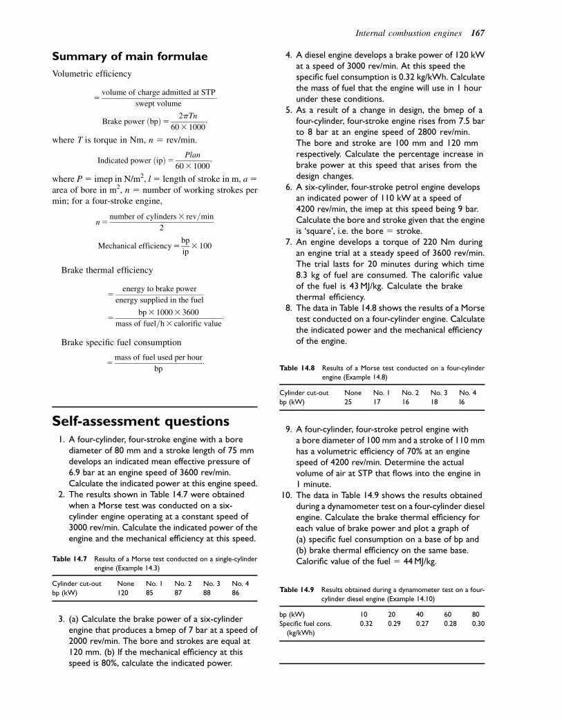
Summary of main formulae
Volumetric efficiency
5volume of charge admitted at STP
swept volume:
Brake power ðbpÞ5 2pTn
603 1000;
where T is torque in Nm, n 5 rev/min.
Indicated power ðipÞ5 Plan
603 1000;
where P5 imep in N/m2, l5 length of stroke in m, a5area of bore in m2, n 5 number of working strokes permin; for a four-stroke engine,
n5number of cylinders3 rev=min
2
Mechanical efficiency5bp
ip3 100
Brake thermal efficiency
5energy to brake power
energy supplied in the fuel
5bp3 10003 3600
mass of fuel=h3 calorific value:
Brake specific fuel consumption
5mass of fuel used per hour
bp:
Self-assessment questions1. A four-cylinder, four-stroke engine with a bore
diameter of 80 mm and a stroke length of 75 mmdevelops an indicated mean effective pressure of6.9 bar at an engine speed of 3600 rev/min.Calculate the indicated power at this engine speed.
2. The results shown in Table 14.7 were obtainedwhen a Morse test was conducted on a six-cylinder engine operating at a constant speed of3000 rev/min. Calculate the indicated power of theengine and the mechanical efficiency at this speed.
3. (a) Calculate the brake power of a six-cylinderengine that produces a bmep of 7 bar at a speed of2000 rev/min. The bore and strokes are equal at120 mm. (b) If the mechanical efficiency at thisspeed is 80%, calculate the indicated power.
4. A diesel engine develops a brake power of 120 kWat a speed of 3000 rev/min. At this speed thespecific fuel consumption is 0.32 kg/kWh. Calculatethe mass of fuel that the engine will use in 1 hourunder these conditions.
5. As a result of a change in design, the bmep of afour-cylinder, four-stroke engine rises from 7.5 barto 8 bar at an engine speed of 2800 rev/min.The bore and stroke are 100 mm and 120 mmrespectively. Calculate the percentage increase inbrake power at this speed that arises from thedesign changes.
6. A six-cylinder, four-stroke petrol engine developsan indicated power of 110 kW at a speed of4200 rev/min, the imep at this speed being 9 bar.Calculate the bore and stroke given that the engineis ‘square’, i.e. the bore 5 stroke.
7. An engine develops a torque of 220 Nm duringan engine trial at a steady speed of 3600 rev/min.The trial lasts for 20 minutes during which time8.3 kg of fuel are consumed. The calorific valueof the fuel is 43MJ/kg. Calculate the brakethermal efficiency.
8. The data in Table 14.8 shows the results of a Morsetest conducted on a four-cylinder engine. Calculatethe indicated power and the mechanical efficiencyof the engine.
9. A four-cylinder, four-stroke petrol engine witha bore diameter of 100 mm and a stroke of 110 mmhas a volumetric efficiency of 70% at an enginespeed of 4200 rev/min. Determine the actualvolume of air at STP that flows into the engine in1 minute.
10. The data in Table 14.9 shows the results obtainedduring a dynamometer test on a four-cylinder dieselengine. Calculate the brake thermal efficiency foreach value of brake power and plot a graph of(a) specific fuel consumption on a base of bp and(b) brake thermal efficiency on the same base.Calorific value of the fuel 5 44MJ/kg.Table 14.7 Results of a Morse test conducted on a single-cylinder
engine (Example 14.3)
Cylinder cut-out None No. 1 No. 2 No. 3 No. 4
bp (kW) 120 85 87 88 86
Table 14.8 Results of a Morse test conducted on a four-cylinder
engine (Example 14.8)
Cylinder cut-out None No. 1 No. 2 No. 3 No. 4
bp (kW) 25 17 16 18 I6
Table 14.9 Results obtained during a dynamometer test on a four-
cylinder diesel engine (Example 14.10)
bp (kW) 10 20 40 60 80
Specific fuel cons.
(kg/kWh)
0.32 0.29 0.27 0.28 0.30
Internal combustion engines 167
15The compression ignition engine ediesel engine
Topics covered in thischapter
The four-stroke compression ignition engine (CIE)The Diesel cycle and the dual combustion cycleThe two-stroke CIEDiesel engine constructionDirect injection engineIndirect injection engineTurbulenceInduction stroke turbulenceCombustion in a compression ignition engineThree phases of combustionDiesel fuel and products of combustionFlash pointPour pointCloud pointProducts of combustionEmissions limitsEmissions control on CIEParticulate trap and selective catalyst reductionExhaust gas recirculation (EGR)
Rudolf Diesel (1858e1913) is generally accepted as theperson who first developed an internal combustion enginethat worked by injecting fuel into compressed air thatwas hot enough to ignite the fuel. His patent used thesewords: ‘Compressing in a cylinder pure air to such anextent that the temperature thereby produced is far higherthan the burning or igniting point of the fuel.’ The orig-inal diesel engines of the type shown in Fig. 15.1(a)were large and heavy, and they operated at slow speed;they were used for stationary engines and ships butwere not considered suitable for use in road vehicles.
Around the 1920s, developments in fuel injectionequipment and other technologies led to the develop-ment of engines of the type shown in Fig. 15.1(b) thatwere suitable for use in road vehicles e these engineswork on a cycle of operations that is known as thedual combustion cycle. For this reason some authorities
suggest that the vehicle engines that work on the prin-ciple of compression ignition should be called compres-sion ignition engines (CIEs). In modern literature theterms are used interchangeably.
The four-stroke compressionignition engine
The four strokes (Fig. 15.2) are:
1. The inlet valve is opened and pure air is drawn intothe cylinder as the piston moves down. This is theinduction stroke.
2. Both of the valves are closed and the piston moves upthe cylinder, compressing the air so that thetemperature rises above the ignition point of the fuel.The high pressure and temperature is achieved bya high compression ratio of approximately 20:1. Asthe piston approaches top dead centre (TDC), fuel isinjected so that ignition has started by the time thatthe piston starts on the next stroke.
3. Both of the valves are closed and the piston is forceddown the cylinder by the expanding gas and fuelinjection continues for a short period. The fuel is shutoff after a few degrees of crank rotation and the highpressure of the gas forces the piston down thecylinder on the power stroke.
4. The exhaust valve is opened and the piston rises inthe cylinder, expelling the spent gas through theexhaust port e at the end of this stroke the engine isready to start the next cycle.
The Diesel cycle and the dualcombustion cycle
The difference between the two theoretical cycles canbe seen in pressureevolume diagrams, which are graphsthat are used to show how the gas pressure and thecylinder volume are related as the piston moves alongthe cylinder.
� 2011 Allan Bonnick and Derek Newbold. Published by Elsevier Ltd. All rights reserved
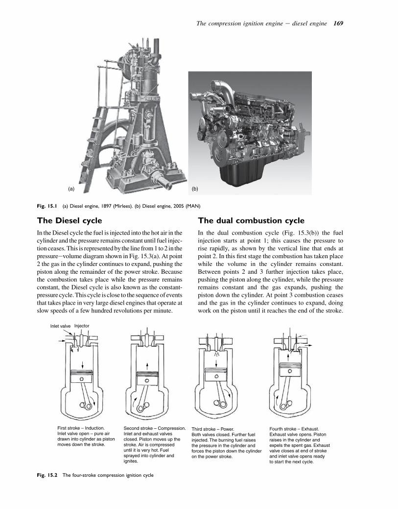
The Diesel cycle
In theDiesel cycle the fuel is injected into the hot air in thecylinder and the pressure remains constant until fuel injec-tionceases. This is representedby the line from1 to2 in thepressureevolume diagram shown in Fig. 15.3(a). At point2 the gas in the cylinder continues to expand, pushing thepiston along the remainder of the power stroke. Becausethe combustion takes place while the pressure remainsconstant, the Diesel cycle is also known as the constant-pressure cycle.This cycle is close to the sequenceof eventsthat takes place in very large diesel engines that operate atslow speeds of a few hundred revolutions per minute.
The dual combustion cycle
In the dual combustion cycle (Fig. 15.3(b)) the fuelinjection starts at point 1; this causes the pressure torise rapidly, as shown by the vertical line that ends atpoint 2. In this first stage the combustion has taken placewhile the volume in the cylinder remains constant.Between points 2 and 3 further injection takes place,pushing the piston along the cylinder, while the pressureremains constant and the gas expands, pushing thepiston down the cylinder. At point 3 combustion ceasesand the gas in the cylinder continues to expand, doingwork on the piston until it reaches the end of the stroke.
(a) (b)
Fig. 15.1 (a) Diesel engine, 1897 (Mirlees). (b) Diesel engine, 2005 (MAN)
Inlet valve Injector
First stroke – Induction.Inlet valve open – pure airdrawn into cylinder as pistonmoves down the stroke.
Second stroke – Compression.Inlet and exhaust valvesclosed. Piston moves up thestroke. Air is compresseduntil it is very hot. Fuelsprayed into cylinder andignites.
Third stroke – Power.Both valves closed. Further fuelinjected. The burning fuel raisesthe pressure in the cylinder andforces the piston down the cylinderon the power stroke.
Fourth stroke – Exhaust.Exhaust valve opens. Pistonraises in the cylinder andexpels the spent gas. Exhaustvalve closes at end of strokeand inlet valve opens readyto start the next cycle.
Fig. 15.2 The four-stroke compression ignition cycle
The compression ignition engine e diesel engine 169
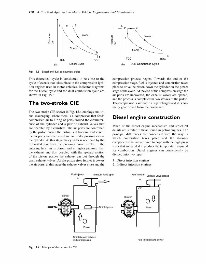
This theoretical cycle is considered to be close to thecycle of events that takes place in the compression igni-tion engines used in motor vehicles. Indicator diagramsfor the Diesel cycle and the dual combustion cycle areshown in Fig. 15.3.
The two-stroke CIE
The two-stroke CIE shown in Fig. 15.4 employs end-to-end scavenging, where there is a compressor that feedscompressed air to a ring of ports around the circumfer-ence of the cylinder and a pair of exhaust valves thatare operated by a camshaft. The air ports are controlledby the piston. When the piston is at bottom dead centrethe air ports are uncovered and air under pressure entersthe cylinder. At this stage the cylinder is occupied by theexhausted gas from the previous power stroke e theentering fresh air is denser and at higher pressure thanthe exhaust and this, coupled with the upward motionof the piston, pushes the exhaust gas out through theopen exhaust valves. As the piston rises further it coversthe air ports; at this stage the exhaust valves close and the
compression process begins. Towards the end of thecompression stage, fuel is injected and combustion takesplace to drive the piston down the cylinder on the powerstage of the cycle. At the end of the compression stage theair ports are uncovered, the exhaust valves are opened,and the process is completed in two strokes of the piston.The compressor is similar to a supercharger and it is nor-mally gear driven from the crankshaft.
Diesel engine construction
Much of the diesel engine mechanism and structuraldetails are similar to those found in petrol engines. Theprincipal differences are concerned with the way inwhich combustion takes place and the strongercomponents that are required to cope with the high pres-sures that are needed to produce the temperature requiredfor combustion. Diesel engines can conveniently bedivided into two types:
1. Direct injection engines2. Indirect injection engines.
Fig. 15.4 Principle of the two-stroke CIE
(a) (b)
TDC
1 2
BDCDiesel Cycle
Power
CompP
ress
ure
bar
1
2 3
TDC BDC
Dual Combustion Cycle
Power
Comp
Pre
ssur
eba
r
Fig. 15.3 Diesel and dual combustion cycles
170 A Practical Approach to Motor Vehicle Engineering and Maintenance

Direct injection engines
In the direct injection engine shown in Fig. 15.5 the fuelis sprayed directly into the cylinder. The circular spacein the piston crown forms part of the combustionchamber; it is designed to produce turbulence whenair is forced in towards the end of the compressionstroke. This type of turbulence is known as ‘squish’turbulence because it is produced by the ‘squashing’of air as the piston forces the air down into the pistoncavity. The injector is normally of the multi-hole typeand operates at a pressure of approximately 180 bar ethe compression ratio of the direct injection engine isof the order of 16:1, which is somewhat lower thanthat used in indirect injection engines.
Indirect injection engines
In the indirect engine (Fig. 15.6) the fuel is sprayedinto a small pre-combustion chamber that is placed inthe cylinder head above the piston. As the pistonapproaches TDC, air is forced into the pre-combustionchamber, which is designed to produce the swirlingaction necessary for good combustion.
The combustion that starts in the pre-chamber rapidlyheats the air and the burning fuel, and air is forced into
the space at the top of the piston, where it mixes with themain body of air to complete the combustion process.The injection pressure in the indirect injection engineis of the order of 120 bar e compression ratios between22:1 and 28:1 are normal in these engines.
Turbulence
Turbulence is required to ensure that all droplets of fuelare surrounded by sufficient air to provide the oxygenthat is required for efficient combustion. There arebasically two methods of creating turbulence:
1. Turbulence created on the induction stroke2. Turbulence created on the compression stroke.
Induction stroke turbulence
Figure 15.7(a) shows the arrangement of the inductionports on a modern diesel engine. The tangential port isdesigned to set up a rotary motion in the air as it passesthrough the port into the cylinder on the inductionstroke, as indicated in Fig. 15.7(b).
Circularcombustionchamber inthe pistoncrown
Coolentjacket
Squish
Air swirl
Piston
InjectorCylinder head
Direct injection
Fig. 15.5 A direct injection engine
The compression ignition engine e diesel engine 171

Special shape inthe piston crowninduces swirl asburning mixtureleaves the pre-combustion chamber
Cylinderblock
Piston
Port
Indirect injection
Pre-combustionchamber
Injector
Fig. 15.6 An indirect injection system
1. Exhaust port2. Exhaust valve3. Fuel injector4. Inlet swirl port5. Inlet valve6. Tangential inlet port7. Heater plug
3
4
5
6
7
(a) (b)
2
1
Fig. 15.7 A tangential inlet port
172 A Practical Approach to Motor Vehicle Engineering and Maintenance
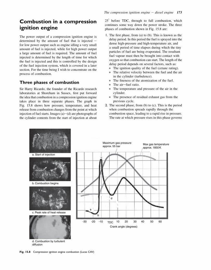
Combustion in a compressionignition engine
The power output of a compression ignition engine isdetermined by the amount of fuel that is injected efor low power output such as engine idling a very smallamount of fuel is injected, while for high power outputa large amount of fuel is required. The amount of fuelinjected is determined by the length of time for whichthe fuel is injected and this is controlled by the designof the fuel injection system, which is covered in a latersection. For the time being I wish to concentrate on theprocess of combustion.
Three phases of combustion
Sir Harry Ricardo, the founder of the Ricardo researchlaboratories at Shoreham in Sussex, first put forwardthe idea that combustion in a compression ignition enginetakes place in three separate phases. The graph inFig. 15.8 shows how pressure, temperature, and heatrelease from combustion changes from the point at whichinjection of fuel starts. Images (a)e(d) are photographs ofthe cylinder contents from the start of injection at about
258 before TDC, through to full combustion, whichcontinues some way down the power stroke. The threephases of combustion shown in Fig. 15.8 are:
1. The first phase, from (a) to (b). This is known as thedelay period. In this period the fuel is sprayed into thedense high-pressure and high-temperature air, anda small period of time elapses during which the tinyparticles of fuel are being evaporated. The resultantfuel vapour must then be brought into contact withoxygen so that combustion can start. The length of thedelay period depends on several factors, such as:� The ignition quality of the fuel (cetane rating).� The relative velocity between the fuel and the air
in the cylinder (turbulence).� The fineness of the atomization of the fuel.� The airefuel ratio.� The temperature and pressure of the air in the
cylinder.� The presence of residual exhaust gas from the
previous cycle.2. The second phase, from (b) to (c). This is the period
when combustion spreads rapidly through thecombustion space, leading to a rapid rise in pressure.The rate at which pressure rises in this phase governs
a. Start of injection
b. Combustion begins
c. Peak rate of heat release
Crank angle (degrees)
-30 -20 -10
a
b
d
c
Maximum gas pressureapprox. 55 bar
Max gas temperatureapprox. 1850 K
10TDC 20 30 40 50 60
d. Combustion by turbulentdiffusion
Fig. 15.8 Compression ignition engine combustion (Lucas CAV)
The compression ignition engine e diesel engine 173
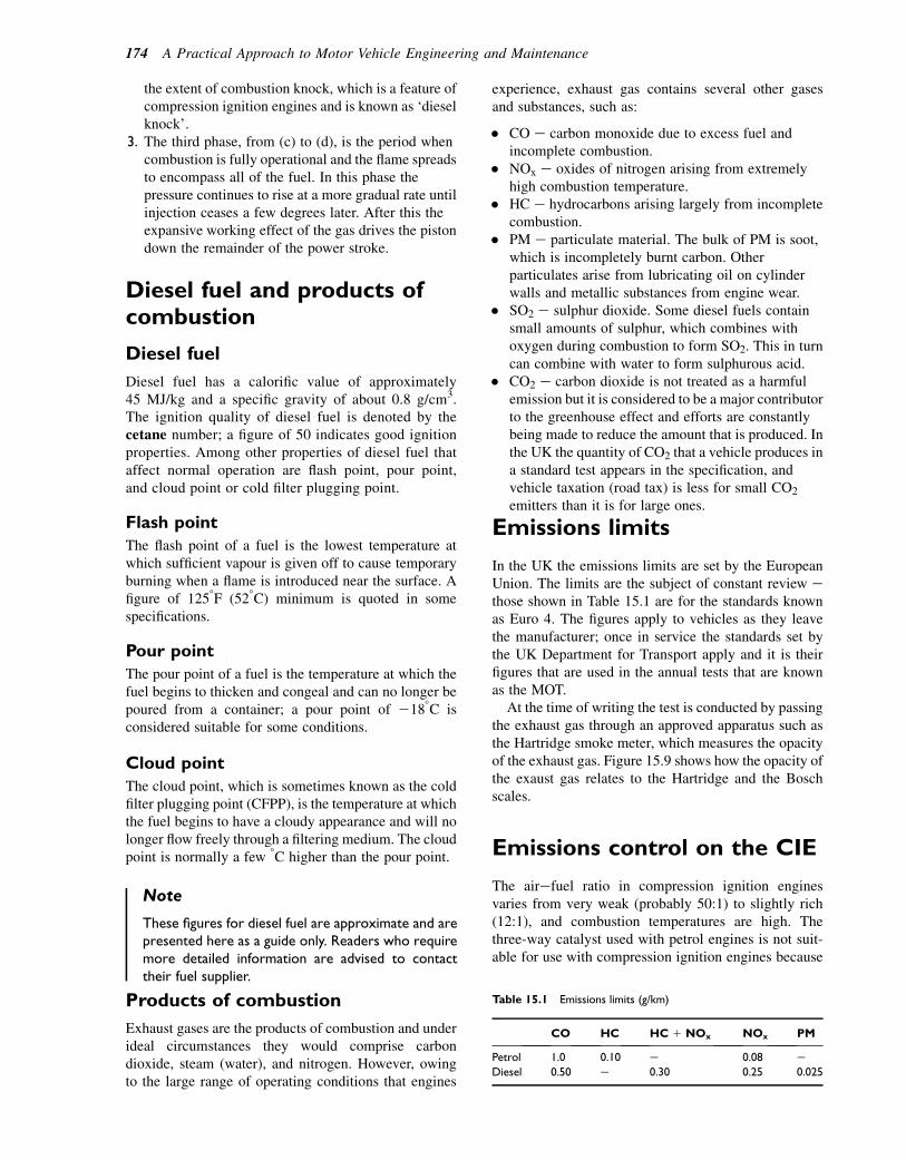
the extent of combustion knock, which is a feature ofcompression ignition engines and is known as ‘dieselknock’.
3. The third phase, from (c) to (d), is the period whencombustion is fully operational and the flame spreadsto encompass all of the fuel. In this phase thepressure continues to rise at a more gradual rate untilinjection ceases a few degrees later. After this theexpansive working effect of the gas drives the pistondown the remainder of the power stroke.
Diesel fuel and products ofcombustion
Diesel fuel
Diesel fuel has a calorific value of approximately45 MJ/kg and a specific gravity of about 0.8 g/cm3.The ignition quality of diesel fuel is denoted by thecetane number; a figure of 50 indicates good ignitionproperties. Among other properties of diesel fuel thataffect normal operation are flash point, pour point,and cloud point or cold filter plugging point.
Flash point
The flash point of a fuel is the lowest temperature atwhich sufficient vapour is given off to cause temporaryburning when a flame is introduced near the surface. Afigure of 1258F (528C) minimum is quoted in somespecifications.
Pour point
The pour point of a fuel is the temperature at which thefuel begins to thicken and congeal and can no longer bepoured from a container; a pour point of 2188C isconsidered suitable for some conditions.
Cloud point
The cloud point, which is sometimes known as the coldfilter plugging point (CFPP), is the temperature at whichthe fuel begins to have a cloudy appearance and will nolonger flow freely through a filtering medium. The cloudpoint is normally a few 8C higher than the pour point.
Note
These figures for diesel fuel are approximate and arepresented here as a guide only. Readers who requiremore detailed information are advised to contacttheir fuel supplier.
Products of combustion
Exhaust gases are the products of combustion and underideal circumstances they would comprise carbondioxide, steam (water), and nitrogen. However, owingto the large range of operating conditions that engines
experience, exhaust gas contains several other gasesand substances, such as:
� CO e carbon monoxide due to excess fuel andincomplete combustion.
� NOx e oxides of nitrogen arising from extremelyhigh combustion temperature.
� HC e hydrocarbons arising largely from incompletecombustion.
� PM e particulate material. The bulk of PM is soot,which is incompletely burnt carbon. Otherparticulates arise from lubricating oil on cylinderwalls and metallic substances from engine wear.
� SO2 e sulphur dioxide. Some diesel fuels containsmall amounts of sulphur, which combines withoxygen during combustion to form SO2. This in turncan combine with water to form sulphurous acid.
� CO2 e carbon dioxide is not treated as a harmfulemission but it is considered to be a major contributorto the greenhouse effect and efforts are constantlybeing made to reduce the amount that is produced. Inthe UK the quantity of CO2 that a vehicle produces ina standard test appears in the specification, andvehicle taxation (road tax) is less for small CO2
emitters than it is for large ones.
Emissions limits
In the UK the emissions limits are set by the EuropeanUnion. The limits are the subject of constant review ethose shown in Table 15.1 are for the standards knownas Euro 4. The figures apply to vehicles as they leavethe manufacturer; once in service the standards set bythe UK Department for Transport apply and it is theirfigures that are used in the annual tests that are knownas the MOT.
At the time of writing the test is conducted by passingthe exhaust gas through an approved apparatus such asthe Hartridge smoke meter, which measures the opacityof the exhaust gas. Figure 15.9 shows how the opacity ofthe exaust gas relates to the Hartridge and the Boschscales.
Emissions control on the CIE
The airefuel ratio in compression ignition enginesvaries from very weak (probably 50:1) to slightly rich(12:1), and combustion temperatures are high. Thethree-way catalyst used with petrol engines is not suit-able for use with compression ignition engines because
Table 15.1 Emissions limits (g/km)
CO HC HC 1 NOx NOx PM
Petrol 1.0 0.10 e 0.08 e
Diesel 0.50 e 0.30 0.25 0.025
174 A Practical Approach to Motor Vehicle Engineering and Maintenance

it requires the airefuel ratio to be held near to 15:1 andalternative methods of dealing with harmful emissionsare used. The two systems that are used on heavy vehi-cles are:
1. Selective catalyst reduction (SCR) and a particulatematter (PM) filter.
2. Exhaust gas recirculation (EGR).
Particulate trap and selectivecatalyst reduction
The three-way catalyst used on petrol engines requiresan airefuel ratio of about 15:1. Diesel engines operateon mixture strengths that may be as low as 40:1, whichmeans that an alternative system is used to reduce NOx.On light vehicles there is a tendency to rely on exhaustgas recirculation to limit NOx and an oxidation catalystto control HC; in addition, a particulate filter may beused to deal with soot and other particulates. Thissystem is shown in outline in Fig. 15.10.
There is some debate in the heavy vehicle field aboutthe most suitable system for exhaust gas after treatment,
and some large vehicles are equipped with an alternativesystem of the type shown in Fig. 15.11.
The exhaust gas is first passed through the oxidationcatalyst and particulate filter. The high concentration ofoxygen in the fueleair mixture and the relatively hightemperature allow the oxidation catalyst to convert HCand CO into CO2 and H2O. The gas then enters the partic-ulate filter, where the soot and other materials are filteredout. Any PM that is deposited in the filter can be removedlater by active regeneration, which is combustion withoxygen at approximately 6008C; this is achieved bya temporary increase in the amount of fuel injected.The regeneration process is performed by the enginemanagement system at intervals dictated by operatingconditions. After passing through the oxidation catalystand particulate filter, a solution of pure water and ureais injected into the exhaust stream, where it reacts withthe catalyst to reduce the NOx to water vapour andnitrogen. In Europe the solution of pure water and ureais called AdBlue and is carried in a small tank that isabout 20% of the capacity of the main fuel tank, and itis normally placed next to it, as shown in Fig. 15.12.
CAT
Oxidising catalyst Particulate filter
Pressure differentialsensor
Oxygen sensor
P.F.
Fig. 15.10 Light diesel exhaust engine emission control
N0x – oxides of nitrogen
Urea injectionNitrogenH2O – Water vapourPlus normal exhaust gas
Hc – hydrocarbons –unburnt fuelPM – soot etc.Plus normal exhaustgas
1. Particular filter2. Oxidation catalyst3. Selective reduction catalyst
1 2 3
Fig. 15.11 A heavy diesel engine selective catalyst reduction system
Light absorption coefficient [m-1]
Hartridge smoke units [HSU]
Bosch number [BN]
0.1
101.0
1.5
2.0
2.5
3.0
3.5
4.0
4.5
5.0
5.5
6.0
6.5
20 30 40 50 60 70 80 90
0.2
0.3
0.40.5
0.60.70.8
0.91.01.11.21.31.41.51.61.71.81.92.0
2.22.4
2.62.83.0
3.5
4.0
5.0
6.07.08.0
7.07.5
Fig. 15.9 Smoke meter scales
The compression ignition engine e diesel engine 175
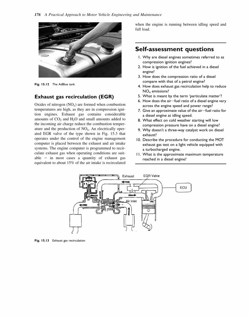
Exhaust gas recirculation (EGR)
Oxides of nitrogen (NOx) are formed when combustiontemperatures are high, as they are in compression igni-tion engines. Exhaust gas contains considerableamounts of CO2 and H2O and small amounts added tothe incoming air charge reduce the combustion temper-ature and the production of NOx. An electrically oper-ated EGR valve of the type shown in Fig. 15.3 thatoperates under the control of the engine managementcomputer is placed between the exhaust and air intakesystems. The engine computer is programmed to recir-culate exhaust gas when operating conditions are suit-able e in most cases a quantity of exhaust gasequivalent to about 15% of the air intake is recirculated
when the engine is running between idling speed andfull load.
Self-assessment questions1. Why are diesel engines sometimes referred to as
compression ignition engines?2. How is ignition of the fuel achieved in a diesel
engine?3. How does the compression ratio of a diesel
compare with that of a petrol engine?4. How does exhaust gas recirculation help to reduce
NOx emissions?5. What is meant by the term ‘particulate matter’?6. How does the airefuel ratio of a diesel engine vary
across the engine speed and power range?7. Give an approximate value of the airefuel ratio for
a diesel engine at idling speed.8. What effect on cold weather starting will low
compression pressure have on a diesel engine?9. Why doesn’t a three-way catalyst work on diesel
exhaust?10. Describe the procedure for conducting the MOT
exhaust gas test on a light vehicle equipped witha turbocharged engine.
11. What is the approximate maximum temperaturereached in a diesel engine?
Fig. 15.13 Exhaust gas recirculation
Fig. 15.12 The AdBlue tank
176 A Practical Approach to Motor Vehicle Engineering and Maintenance
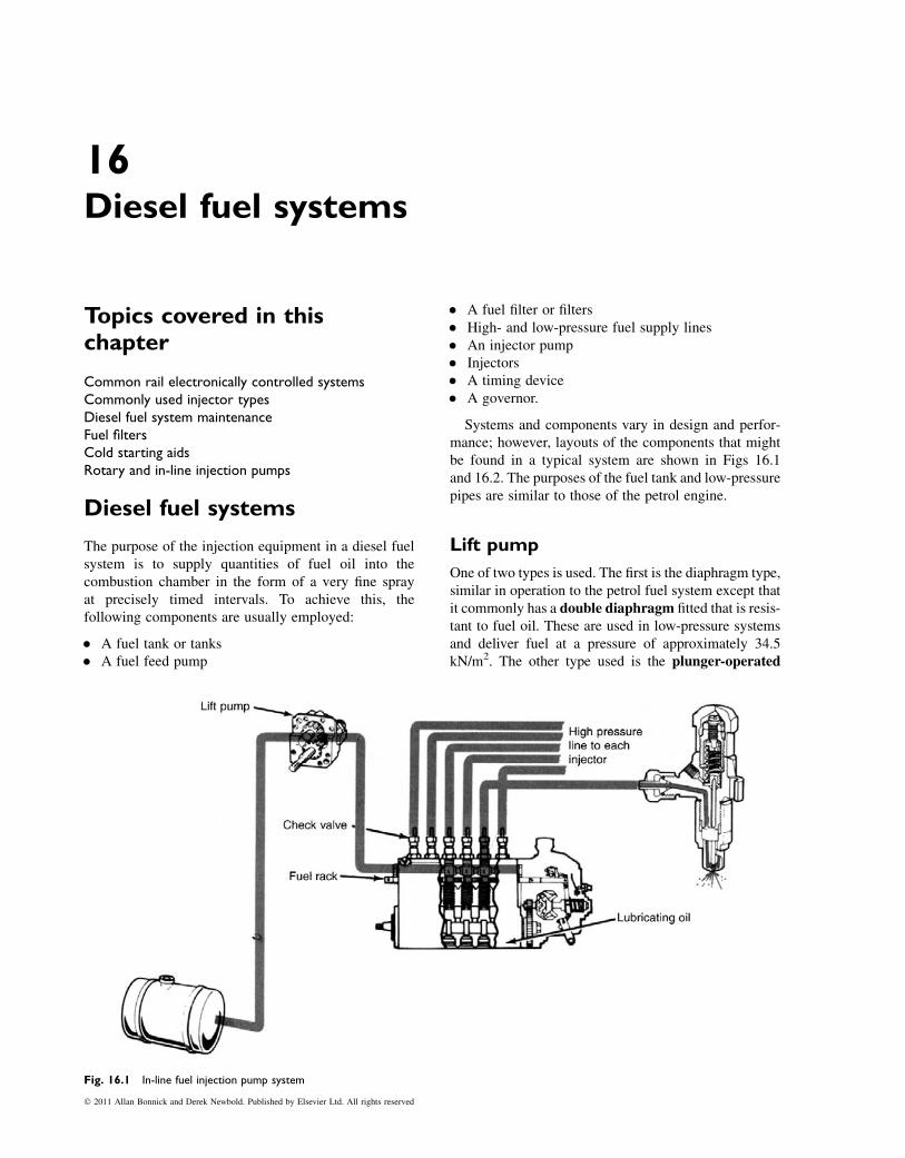
16Diesel fuel systems
Topics covered in thischapter
Common rail electronically controlled systemsCommonly used injector typesDiesel fuel system maintenanceFuel filtersCold starting aidsRotary and in-line injection pumps
Diesel fuel systems
The purpose of the injection equipment in a diesel fuelsystem is to supply quantities of fuel oil into thecombustion chamber in the form of a very fine sprayat precisely timed intervals. To achieve this, thefollowing components are usually employed:
� A fuel tank or tanks� A fuel feed pump
� A fuel filter or filters� High- and low-pressure fuel supply lines� An injector pump� Injectors� A timing device� A governor.
Systems and components vary in design and perfor-mance; however, layouts of the components that mightbe found in a typical system are shown in Figs 16.1and 16.2. The purposes of the fuel tank and low-pressurepipes are similar to those of the petrol engine.
Lift pump
One of two types is used. The first is the diaphragm type,similar in operation to the petrol fuel system except thatit commonly has a double diaphragm fitted that is resis-tant to fuel oil. These are used in low-pressure systemsand deliver fuel at a pressure of approximately 34.5kN/m2. The other type used is the plunger-operated
Fig. 16.1 In-line fuel injection pump system
� 2011 Allan Bonnick and Derek Newbold. Published by Elsevier Ltd. All rights reserved
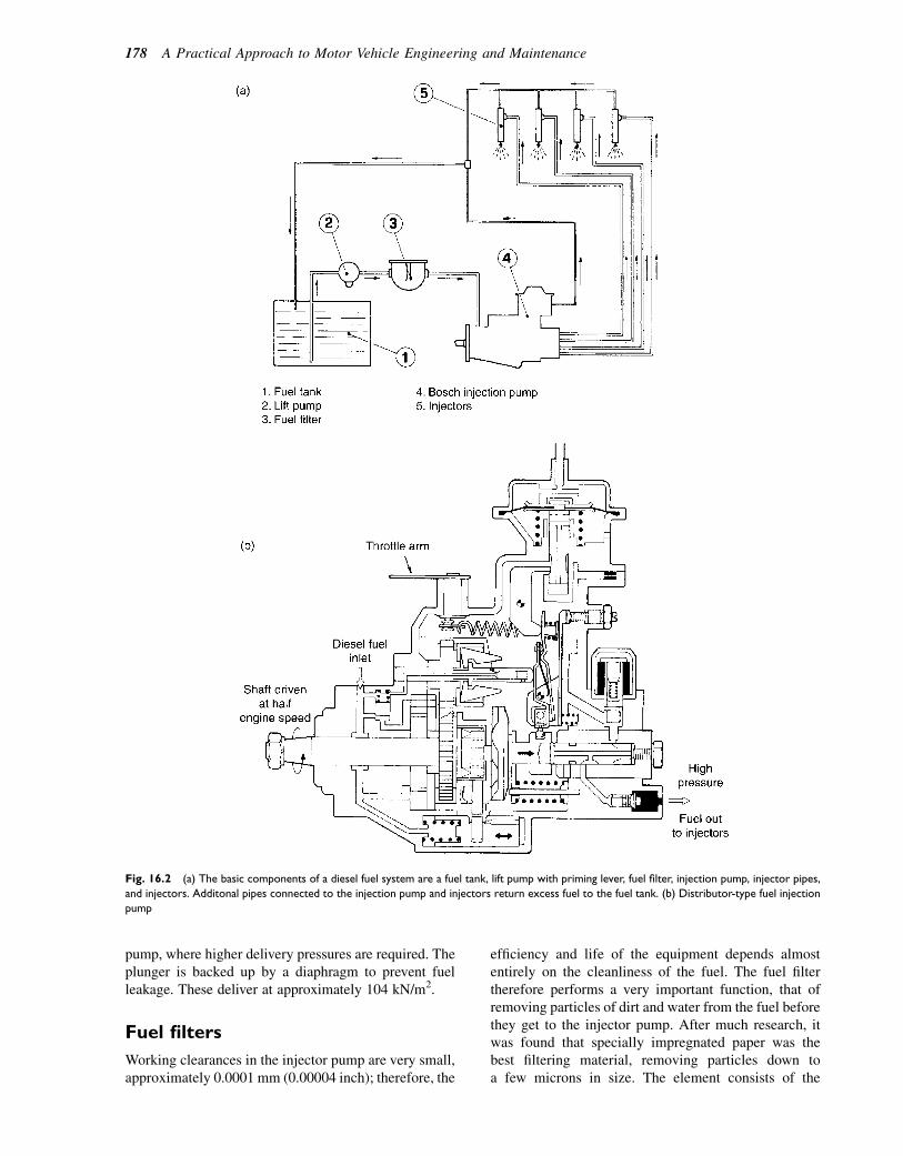
pump, where higher delivery pressures are required. Theplunger is backed up by a diaphragm to prevent fuelleakage. These deliver at approximately 104 kN/m2.
Fuel filters
Working clearances in the injector pump are very small,approximately 0.0001 mm (0.00004 inch); therefore, the
efficiency and life of the equipment depends almostentirely on the cleanliness of the fuel. The fuel filtertherefore performs a very important function, that ofremoving particles of dirt and water from the fuel beforethey get to the injector pump. After much research, itwas found that specially impregnated paper was thebest filtering material, removing particles down toa few microns in size. The element consists of the
Fig. 16.2 (a) The basic components of a diesel fuel system are a fuel tank, lift pump with priming lever, fuel filter, injection pump, injector pipes,
and injectors. Additonal pipes connected to the injection pump and injectors return excess fuel to the fuel tank. (b) Distributor-type fuel injection
pump
178 A Practical Approach to Motor Vehicle Engineering and Maintenance
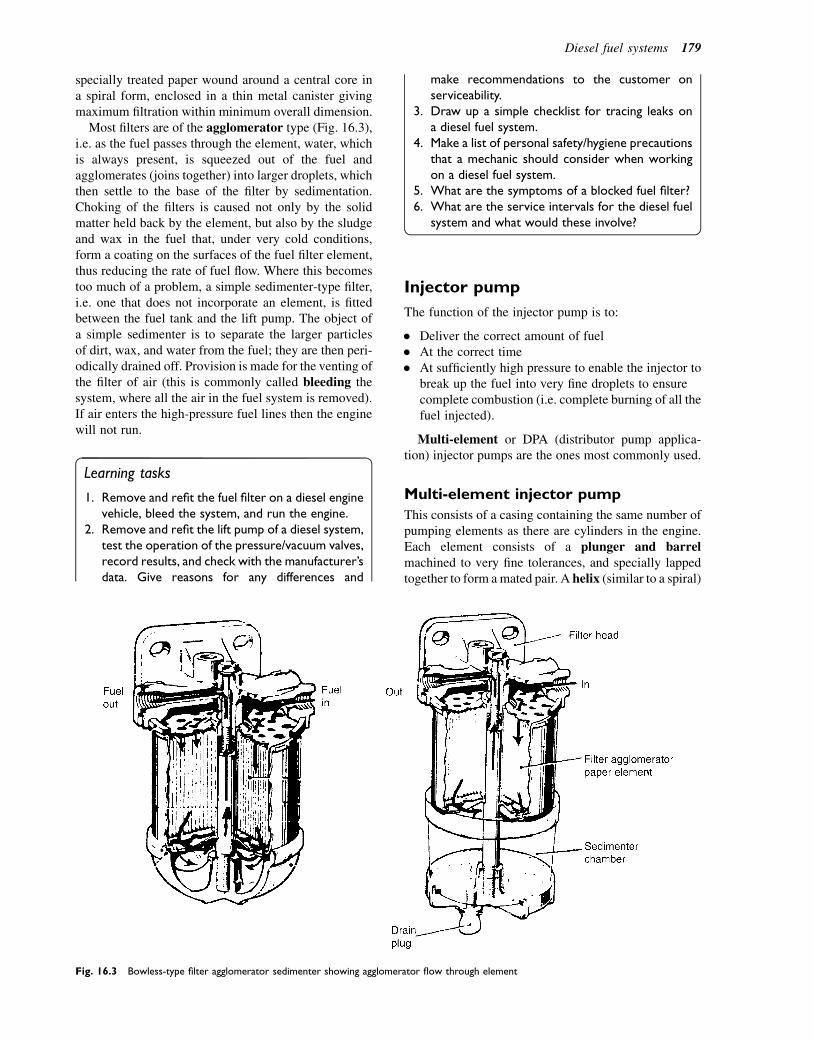
specially treated paper wound around a central core ina spiral form, enclosed in a thin metal canister givingmaximum filtration within minimum overall dimension.
Most filters are of the agglomerator type (Fig. 16.3),i.e. as the fuel passes through the element, water, whichis always present, is squeezed out of the fuel andagglomerates (joins together) into larger droplets, whichthen settle to the base of the filter by sedimentation.Choking of the filters is caused not only by the solidmatter held back by the element, but also by the sludgeand wax in the fuel that, under very cold conditions,form a coating on the surfaces of the fuel filter element,thus reducing the rate of fuel flow. Where this becomestoo much of a problem, a simple sedimenter-type filter,i.e. one that does not incorporate an element, is fittedbetween the fuel tank and the lift pump. The object ofa simple sedimenter is to separate the larger particlesof dirt, wax, and water from the fuel; they are then peri-odically drained off. Provision is made for the venting ofthe filter of air (this is commonly called bleeding thesystem, where all the air in the fuel system is removed).If air enters the high-pressure fuel lines then the enginewill not run.
Learning tasks
1. Remove and refit the fuel filter on a diesel enginevehicle, bleed the system, and run the engine.
2. Remove and refit the lift pump of a diesel system,test the operation of the pressure/vacuum valves,record results, and check with the manufacturer’sdata. Give reasons for any differences and
make recommendations to the customer onserviceability.
3. Draw up a simple checklist for tracing leaks ona diesel fuel system.
4. Make a list of personal safety/hygiene precautionsthat a mechanic should consider when workingon a diesel fuel system.
5. What are the symptoms of a blocked fuel filter?6. What are the service intervals for the diesel fuel
system and what would these involve?
Injector pump
The function of the injector pump is to:
� Deliver the correct amount of fuel� At the correct time� At sufficiently high pressure to enable the injector to
break up the fuel into very fine droplets to ensurecomplete combustion (i.e. complete burning of all thefuel injected).
Multi-element or DPA (distributor pump applica-tion) injector pumps are the ones most commonly used.
Multi-element injector pump
This consists of a casing containing the same number ofpumping elements as there are cylinders in the engine.Each element consists of a plunger and barrelmachined to very fine tolerances, and specially lappedtogether to form amated pair. A helix (similar to a spiral)
Fig. 16.3 Bowless-type filter agglomerator sedimenter showing agglomerator flow through element
Diesel fuel systems 179
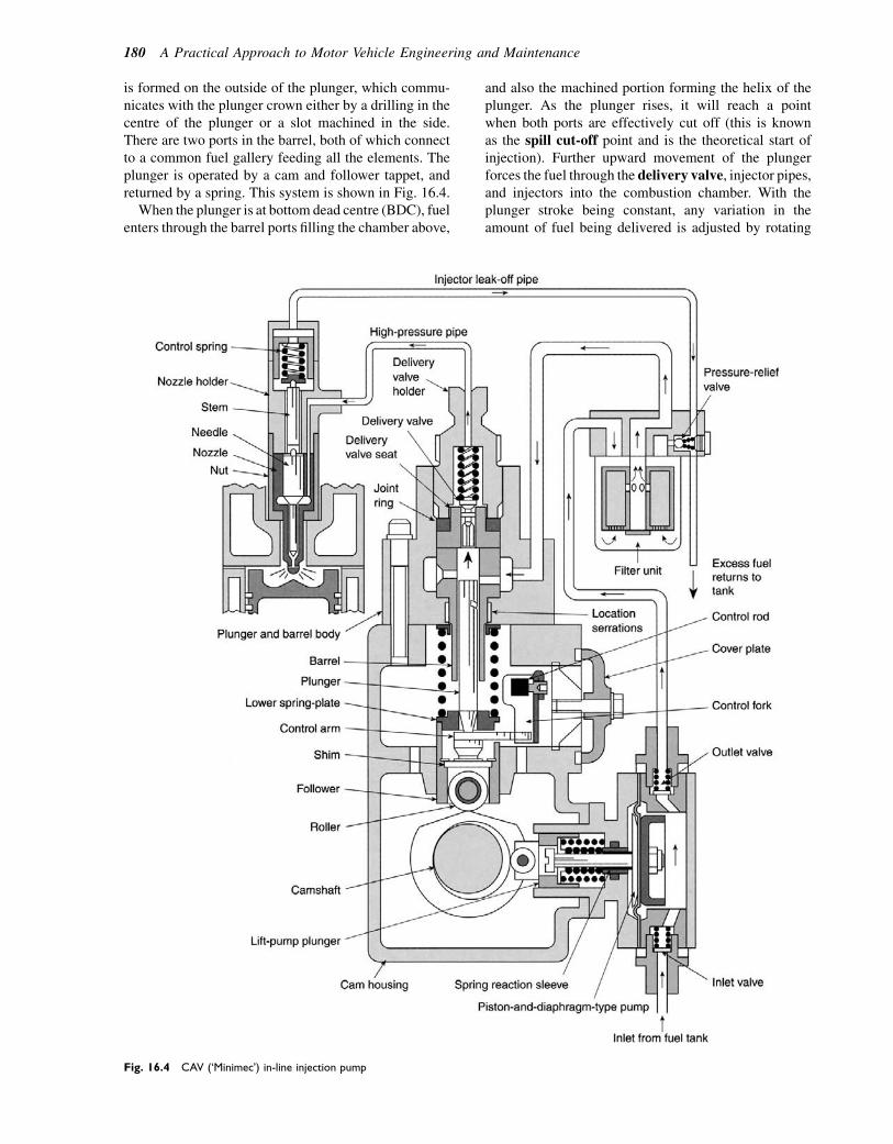
is formed on the outside of the plunger, which commu-nicates with the plunger crown either by a drilling in thecentre of the plunger or a slot machined in the side.There are two ports in the barrel, both of which connectto a common fuel gallery feeding all the elements. Theplunger is operated by a cam and follower tappet, andreturned by a spring. This system is shown in Fig. 16.4.
When the plunger is at bottom dead centre (BDC), fuelenters through the barrel ports filling the chamber above,
and also the machined portion forming the helix of theplunger. As the plunger rises, it will reach a pointwhen both ports are effectively cut off (this is knownas the spill cut-off point and is the theoretical start ofinjection). Further upward movement of the plungerforces the fuel through the delivery valve, injector pipes,and injectors into the combustion chamber. With theplunger stroke being constant, any variation in theamount of fuel being delivered is adjusted by rotating
Fig. 16.4 CAV (‘Minimec’) in-line injection pump
180 A Practical Approach to Motor Vehicle Engineering and Maintenance
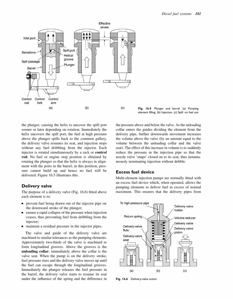
the plunger, causing the helix to uncover the spill portsooner or later depending on rotation. Immediately thehelix uncovers the spill port, the fuel at high pressureabove the plunger spills back to the common gallery,the delivery valve resumes its seat, and injection stopswithout any fuel dribbling from the injector. Eachinjector is rotated simultaneously by a rack or controlrod. No fuel or engine stop position is obtained byrotating the plunger so that the helix is always in align-ment with the ports in the barrel; in this position, pres-sure cannot build up and hence no fuel will bedelivered. Figure 16.5 illustrates this.
Delivery valve
The purpose of a delivery valve (Fig. 16.6) fitted aboveeach element is to:
� prevent fuel being drawn out of the injector pipe onthe downward stroke of the plunger;
� ensure a rapid collapse of the pressure when injectionceases, thus preventing fuel from dribbling from theinjector;
� maintain a residual pressure in the injector pipes.
The valve and guide of the delivery valve aremachined to similar tolerances as the pumping elements.Approximately two-thirds of the valve is machined toform longitudinal grooves. Above the grooves is theunloading collar; immediately above the collar is thevalve seat. When the pump is on the delivery stroke,fuel pressure rises and the delivery valve moves up untilthe fuel can escape through the longitudinal grooves.Immediately the plunger releases the fuel pressure inthe barrel, the delivery valve starts to resume its seatunder the influence of the spring and the difference in
the pressure above and below the valve. As the unloadingcollar enters the guides dividing the element from thedelivery pipe, further downwards movement increasesthe volume above the valve (by an amount equal to thevolume between the unloading collar and the valveseat). The effect of this increase in volume is to suddenlyreduce the pressure in the injection pipe so that thenozzle valve ‘snaps’ closed on to its seat, thus instanta-neously terminating injection without dribble.
Excess fuel device
Multi-element injection pumps are normally fitted withan excess fuel device which, when operated, allows thepumping elements to deliver fuel in excess of normalmaximum. This ensures that the delivery pipes from
Fig. 16.5 Plunger and barrel. (a) Pumping
element filling. (b) Injection. (c) Spill: no fuel out
Fig. 16.6 Delivery-valve action
Diesel fuel systems 181
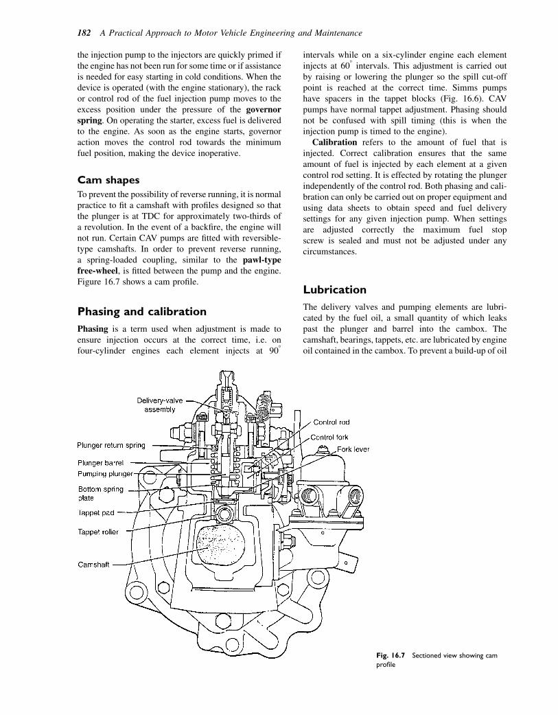
the injection pump to the injectors are quickly primed ifthe engine has not been run for some time or if assistanceis needed for easy starting in cold conditions. When thedevice is operated (with the engine stationary), the rackor control rod of the fuel injection pump moves to theexcess position under the pressure of the governorspring. On operating the starter, excess fuel is deliveredto the engine. As soon as the engine starts, governoraction moves the control rod towards the minimumfuel position, making the device inoperative.
Cam shapes
To prevent the possibility of reverse running, it is normalpractice to fit a camshaft with profiles designed so thatthe plunger is at TDC for approximately two-thirds ofa revolution. In the event of a backfire, the engine willnot run. Certain CAV pumps are fitted with reversible-type camshafts. In order to prevent reverse running,a spring-loaded coupling, similar to the pawl-typefree-wheel, is fitted between the pump and the engine.Figure 16.7 shows a cam profile.
Phasing and calibration
Phasing is a term used when adjustment is made toensure injection occurs at the correct time, i.e. onfour-cylinder engines each element injects at 908
intervals while on a six-cylinder engine each elementinjects at 608 intervals. This adjustment is carried outby raising or lowering the plunger so the spill cut-offpoint is reached at the correct time. Simms pumpshave spacers in the tappet blocks (Fig. 16.6). CAVpumps have normal tappet adjustment. Phasing shouldnot be confused with spill timing (this is when theinjection pump is timed to the engine).
Calibration refers to the amount of fuel that isinjected. Correct calibration ensures that the sameamount of fuel is injected by each element at a givencontrol rod setting. It is effected by rotating the plungerindependently of the control rod. Both phasing and cali-bration can only be carried out on proper equipment andusing data sheets to obtain speed and fuel deliverysettings for any given injection pump. When settingsare adjusted correctly the maximum fuel stopscrew is sealed and must not be adjusted under anycircumstances.
Lubrication
The delivery valves and pumping elements are lubri-cated by the fuel oil, a small quantity of which leakspast the plunger and barrel into the cambox. Thecamshaft, bearings, tappets, etc. are lubricated by engineoil contained in the cambox. To prevent a build-up of oil
Fig. 16.7 Sectioned view showing cam
profile
182 A Practical Approach to Motor Vehicle Engineering and Maintenance
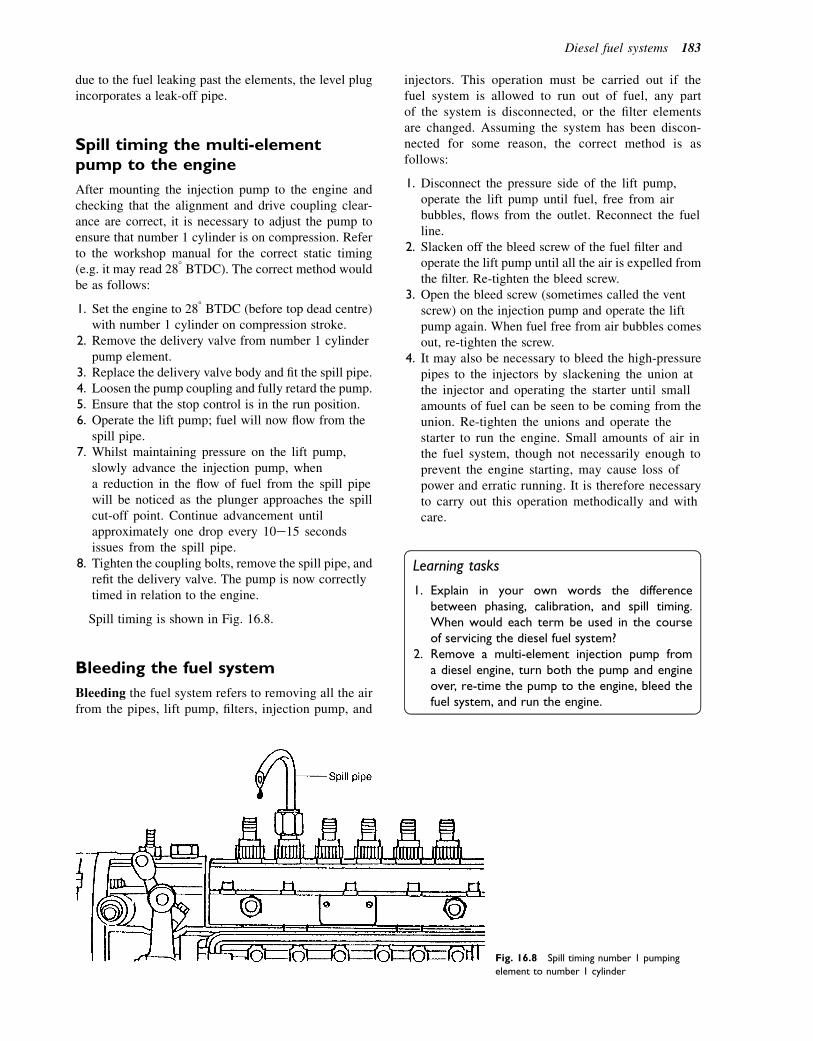
due to the fuel leaking past the elements, the level plugincorporates a leak-off pipe.
Spill timing the multi-elementpump to the engine
After mounting the injection pump to the engine andchecking that the alignment and drive coupling clear-ance are correct, it is necessary to adjust the pump toensure that number 1 cylinder is on compression. Referto the workshop manual for the correct static timing(e.g. it may read 288 BTDC). The correct method wouldbe as follows:
1. Set the engine to 288 BTDC (before top dead centre)with number 1 cylinder on compression stroke.
2. Remove the delivery valve from number 1 cylinderpump element.
3. Replace the delivery valve body and fit the spill pipe.4. Loosen the pump coupling and fully retard the pump.5. Ensure that the stop control is in the run position.6. Operate the lift pump; fuel will now flow from the
spill pipe.7. Whilst maintaining pressure on the lift pump,
slowly advance the injection pump, whena reduction in the flow of fuel from the spill pipewill be noticed as the plunger approaches the spillcut-off point. Continue advancement untilapproximately one drop every 10e15 secondsissues from the spill pipe.
8. Tighten the coupling bolts, remove the spill pipe, andrefit the delivery valve. The pump is now correctlytimed in relation to the engine.
Spill timing is shown in Fig. 16.8.
Bleeding the fuel system
Bleeding the fuel system refers to removing all the airfrom the pipes, lift pump, filters, injection pump, and
injectors. This operation must be carried out if thefuel system is allowed to run out of fuel, any partof the system is disconnected, or the filter elementsare changed. Assuming the system has been discon-nected for some reason, the correct method is asfollows:
1. Disconnect the pressure side of the lift pump,operate the lift pump until fuel, free from airbubbles, flows from the outlet. Reconnect the fuelline.
2. Slacken off the bleed screw of the fuel filter andoperate the lift pump until all the air is expelled fromthe filter. Re-tighten the bleed screw.
3. Open the bleed screw (sometimes called the ventscrew) on the injection pump and operate the liftpump again. When fuel free from air bubbles comesout, re-tighten the screw.
4. It may also be necessary to bleed the high-pressurepipes to the injectors by slackening the union atthe injector and operating the starter until smallamounts of fuel can be seen to be coming from theunion. Re-tighten the unions and operate thestarter to run the engine. Small amounts of air inthe fuel system, though not necessarily enough toprevent the engine starting, may cause loss ofpower and erratic running. It is therefore necessaryto carry out this operation methodically and withcare.
Learning tasks
1. Explain in your own words the differencebetween phasing, calibration, and spill timing.When would each term be used in the courseof servicing the diesel fuel system?
2. Remove a multi-element injection pump froma diesel engine, turn both the pump and engineover, re-time the pump to the engine, bleed thefuel system, and run the engine.
Fig. 16.8 Spill timing number 1 pumping
element to number 1 cylinder
Diesel fuel systems 183
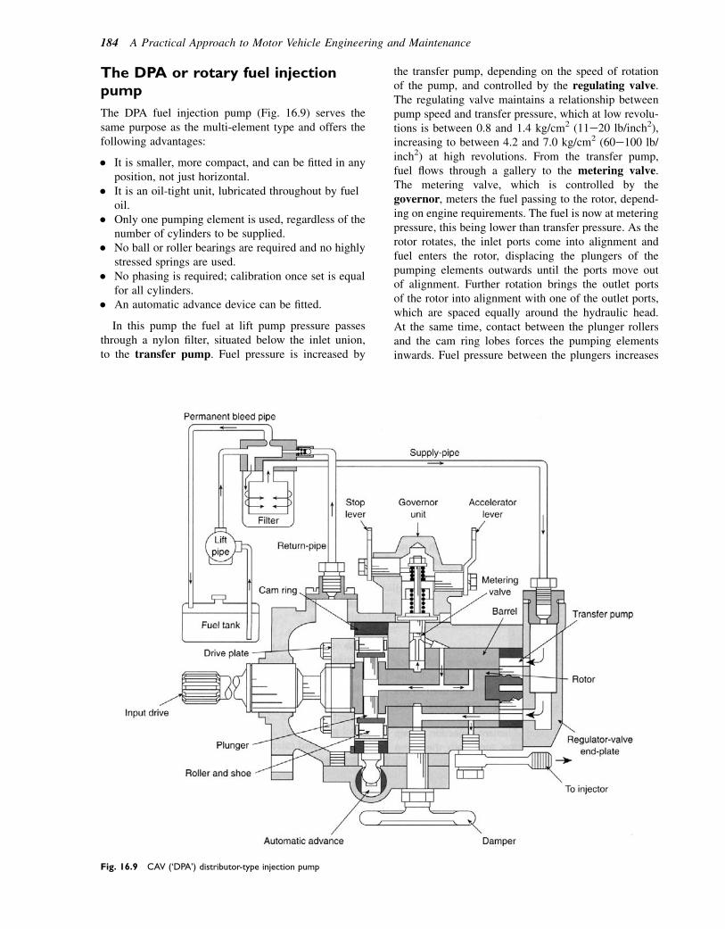
The DPA or rotary fuel injectionpump
The DPA fuel injection pump (Fig. 16.9) serves thesame purpose as the multi-element type and offers thefollowing advantages:
� It is smaller, more compact, and can be fitted in anyposition, not just horizontal.
� It is an oil-tight unit, lubricated throughout by fueloil.
� Only one pumping element is used, regardless of thenumber of cylinders to be supplied.
� No ball or roller bearings are required and no highlystressed springs are used.
� No phasing is required; calibration once set is equalfor all cylinders.
� An automatic advance device can be fitted.
In this pump the fuel at lift pump pressure passesthrough a nylon filter, situated below the inlet union,to the transfer pump. Fuel pressure is increased by
the transfer pump, depending on the speed of rotationof the pump, and controlled by the regulating valve.The regulating valve maintains a relationship betweenpump speed and transfer pressure, which at low revolu-tions is between 0.8 and 1.4 kg/cm2 (11e20 lb/inch2),increasing to between 4.2 and 7.0 kg/cm2 (60e100 lb/inch2) at high revolutions. From the transfer pump,fuel flows through a gallery to the metering valve.The metering valve, which is controlled by thegovernor, meters the fuel passing to the rotor, depend-ing on engine requirements. The fuel is now at meteringpressure, this being lower than transfer pressure. As therotor rotates, the inlet ports come into alignment andfuel enters the rotor, displacing the plungers of thepumping elements outwards until the ports move outof alignment. Further rotation brings the outlet portsof the rotor into alignment with one of the outlet ports,which are spaced equally around the hydraulic head.At the same time, contact between the plunger rollersand the cam ring lobes forces the pumping elementsinwards. Fuel pressure between the plungers increases
Fig. 16.9 CAV (‘DPA’) distributor-type injection pump
184 A Practical Approach to Motor Vehicle Engineering and Maintenance
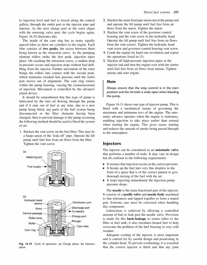
to injection level and fuel is forced along the controlgallery, through the outlet port to the injector pipe andinjector. As the next charge port in the rotor alignswith the metering valve port, the cycle begins again.Figure 16.10 illustrates this.
The inside of the cam ring has as many equallyspaced lobes as there are cylinders in the engine. Eachlobe consists of two peaks, the recess between thembeing known as the retraction curve. As the pumpingelement rollers strike the first peak, injection takesplace. On reaching the retraction curve, a sudden dropin pressure occurs and injection stops without fuel drib-bling from the injector. Further movement of the rotorbrings the rollers into contact with the second peak,which maintains residual line pressure until the outletport moves out of alignment. The cam ring rotateswithin the pump housing, varying the commencementof injection. Movement is controlled by the advance/retard device.
It should be remembered that this type of pump islubricated by the fuel oil flowing through the pumpand if it runs out of fuel at any time, due to a newpump being fitted, any parts of the fuel system beingdisconnected or the filter elements having beenchanged, then to prevent damage to the pump occurringthe following method should be used to bleed the systemof air:
1. Slacken the vent screw on the fuel filter. This may bea banjo union of the ‘leak-off’ pipe. Operate the liftpump until fuel free from air flows from the filter.Tighten the vent screw.
2. Slacken the main feed pipe union nut at the pump endand operate the lift pump until fuel free from airflows from the union. Tighten the union.
3. Slacken the vent screw of the governor controlhousing and the vent screw in the hydraulic head.Operate the lift pump until fuel free from air flowsfrom the vent screws. Tighten the hydraulic headvent screw and governor control housing vent screw.
4. Crank the engine by hand one revolution and repeatthe operations listed in (3).
5. Slacken all high-pressure injection pipes at theinjector end and turn the engine over with the starteruntil fuel free from air flows from unions. Tightenunions and start engine.
Note
Always ensure that the stop control is in the startposition and the throttle is wide open when bleedingthe pump.
Figure 16.11 shows one type of injector pump. This isfitted with a mechanical means of governing themaximum and minimum revs of the engine. The auto-matic advance operates when the engine is stationary,enabling injection to take place earlier than normalwhen starting the engine. This gives easier startingand reduces the amount of smoke being passed throughto the atmosphere.
Injectors
The injector can be considered as an automatic valvethat performs a number of tasks. It may vary in designbut all conform to the following requirements:
� It ensures that injection occurs at the correct pressure.� It breaks up the fuel into very fine droplets in the
form of a spray that is of the correct pattern to givethorough mixing of the fuel with the air.
� It stops injecting immediately the injection pumppressure drops.
The nozzle is the main functional part of the injector.It consists of a needle valve and nozzle body machinedto fine tolerances and lapped together to form a matedpair. Extreme care must be exercised when handlingthis component.
Lubrication is achieved by allowing a controlledamount of fuel to leak past the needle valve. Provisionis made for this back-leakage to return either to thefilter or fuel tank; it also circulates heated fuel to helpovercome the problem of the fuel freezing in very coldweather.
Adequate cooling of the injector is most importantand is catered for by careful design and positioning inthe cylinder head. To prevent overheating, it is essentialthat the correct injector is fitted and that any joint
Fig. 16.10 Cycle of operation. (a) Charge phase. (b) Injection
phase
Diesel fuel systems 185
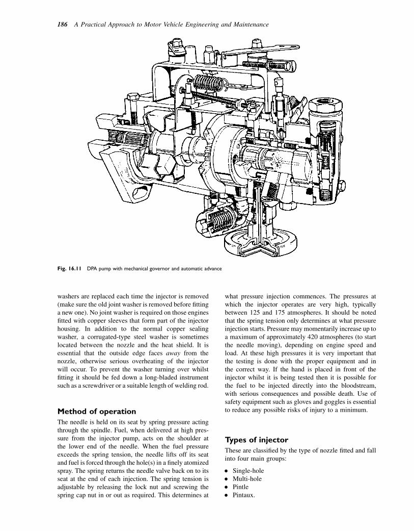
washers are replaced each time the injector is removed(make sure the old joint washer is removed before fittinga new one). No joint washer is required on those enginesfitted with copper sleeves that form part of the injectorhousing. In addition to the normal copper sealingwasher, a corrugated-type steel washer is sometimeslocated between the nozzle and the heat shield. It isessential that the outside edge faces away from thenozzle, otherwise serious overheating of the injectorwill occur. To prevent the washer turning over whilstfitting it should be fed down a long-bladed instrumentsuch as a screwdriver or a suitable length of welding rod.
Method of operation
The needle is held on its seat by spring pressure actingthrough the spindle. Fuel, when delivered at high pres-sure from the injector pump, acts on the shoulder atthe lower end of the needle. When the fuel pressureexceeds the spring tension, the needle lifts off its seatand fuel is forced through the hole(s) in a finely atomizedspray. The spring returns the needle valve back on to itsseat at the end of each injection. The spring tension isadjustable by releasing the lock nut and screwing thespring cap nut in or out as required. This determines at
what pressure injection commences. The pressures atwhich the injector operates are very high, typicallybetween 125 and 175 atmospheres. It should be notedthat the spring tension only determines at what pressureinjection starts. Pressure may momentarily increase up toa maximum of approximately 420 atmospheres (to startthe needle moving), depending on engine speed andload. At these high pressures it is very important thatthe testing is done with the proper equipment and inthe correct way. If the hand is placed in front of theinjector whilst it is being tested then it is possible forthe fuel to be injected directly into the bloodstream,with serious consequences and possible death. Use ofsafety equipment such as gloves and goggles is essentialto reduce any possible risks of injury to a minimum.
Types of injector
These are classified by the type of nozzle fitted and fallinto four main groups:
� Single-hole� Multi-hole� Pintle� Pintaux.
Fig. 16.11 DPA pump with mechanical governor and automatic advance
186 A Practical Approach to Motor Vehicle Engineering and Maintenance

Single- and multi-hole injectors
The single-hole nozzle has one hole drilled centrally inits body, which is closed by the needle valve. The holecan be of any diameter from 0.2 mm (0.008 in.)upwards. This type is now rarely used in motor vehicleengines.Multi-hole injectors (Fig. 16.12) have a varyingnumber of holes drilled in the bulbous end of the nozzlebeneath the needle valve seating. The actual number,size, and position depends on the requirements of theengine concerned. There are usually three or four.This is the type that is fitted to the direct injectionengine, which, due to the larger combustion chamber,requires the fuel to be injected in a number of spraysat high pressure to ensure even distribution and goodpenetration of fuel into the rapidly moving air stream.They are often of the long stem type to give goodcooling of the injector.
Pintle
This nozzle is designed for use with indirect injec-tion combustion chambers. The needle valve stem isextended to form a pintle, which protrudes beyondthe mouth of the nozzle body. By modifying thesize and shape of this pintle, the spray angle can bealtered from parallel to a 608 angle or more. A modi-fied pintle nozzle, known as the delay type, givesa reduced rate of injection at the beginning ofdelivery. This gives quieter running at idling speedon certain engines.
Pintaux nozzles
A development of the pintle-type nozzle, these havean auxiliary hole to assist starting in cold conditions.At cranking speeds, the pressure rise is slow and theneedle valve is not lifted high enough for the pintleto clear the main discharge port. The fuel passingthe seat is sprayed from the auxiliary hole towardsthe hottest part of the combustion chamber (whichis within the area of the heater plug). At normalrunning speeds, the rapid pressure rise lifts the pintleclear of the main discharge port, allowing the fuel toform the appropriate spray pattern. Approximately10% of the fuel continues to pass through the
Fig. 16.13 (a) Hole-type nozzles. (b) Pintle-type nozzles
Fig. 16.12 Multi-hole injector
Diesel fuel systems 187
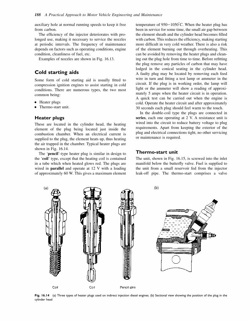
auxiliary hole at normal running speeds to keep it freefrom carbon.
The efficiency of the injector deteriorates with pro-longed use, making it necessary to service the nozzlesat periodic intervals. The frequency of maintenancedepends on factors such as operating conditions, enginecondition, cleanliness of fuel, etc.
Examples of nozzles are shown in Fig. 16.13.
Cold starting aids
Some form of cold starting aid is usually fitted tocompression ignition engines to assist starting in coldconditions. There are numerous types, the two mostcommon being:
� Heater plugs� Thermo-start unit.
Heater plugs
These are located in the cylinder head, the heatingelement of the plug being located just inside thecombustion chamber. When an electrical current issupplied to the plug, the element heats up, thus heatingthe air trapped in the chamber. Typical heater plugs areshown in Fig. 16.14.
The ‘pencil’-type heater plug is similar in design tothe ‘coil’ type, except that the heating coil is containedin a tube which when heated glows red. The plugs arewired in parallel and operate at 12 V with a loadingof approximately 60 W. This gives a maximum element
temperature of 950e10508C. When the heater plug hasbeen in service for some time, the small air gap betweenthe element sheath and the cylinder head becomes filledwith carbon. This reduces the efficiency, making startingmore difficult in very cold weather. There is also a riskof the element burning out through overheating. Thiscan be avoided by removing the heater plugs and clean-ing out the plug hole from time to time. Before refittingthe plug remove any particles of carbon that may havelodged in the conical seating in the cylinder head.A faulty plug may be located by removing each feedwire in turn and fitting a test lamp or ammeter in thecircuit. If the plug is in working order, the lamp willlight or the ammeter will show a reading of approxi-mately 5 amps when the heater circuit is in operation.A quick test can be carried out when the engine iscold. Operate the heater circuit and after approximately30 seconds each plug should feel warm to the touch.
In the double-coil type the plugs are connected inseries, each one operating at 2 V. A resistance unit iswired into the circuit to reduce battery voltage to plugrequirements. Apart from keeping the exterior of theplug and electrical connections tight, no other servicingor maintenance is required.
Thermo-start unit
The unit, shown in Fig. 16.15, is screwed into the inletmanifold below the butterfly valve. Fuel is supplied tothe unit from a small reservoir fed from the injectorleak-off pipe. The thermo-start comprises a valve
Fig. 16.14 (a) Three types of heater plugs used on indirect injection diesel engines. (b) Sectional view showing the position of the plug in the
cylinder head
188 A Practical Approach to Motor Vehicle Engineering and Maintenance

surrounded by a heater coil, an extension of which formsthe igniter. The valve body houses a spindle, whichholds a ball valve in position against a seat, preventingfuel entering the device. When an electric current issupplied to the unit, the valve body is heated by thecoil and expands. This releases the ball valve from itsseat, allowing fuel to enter the manifold, where it isvaporized by the heat. When the engine is cranked, airis drawn into the manifold and the vapour is ignitedby the coil extension, thus heating the air being drawninto the engine. On switching off the current to theunit, the valve body contracts and the spindle returnsthe valve to its seat, cutting off the fuel supply.The reservoir must be positioned 10e25 cm above thethermo-start unit to provide a positive fuel supply.This unit gives very little trouble in service providedthe preheat time before operating the starter does notexceed that recommended (approximately 15 seconds).
Electrical connections
The heater plugs are connected so that when the ignitionis switched on the warning lamp on the dashboard is illu-minated; this warns the driver that the heater plugs areoperating (warming up). The starter should not be oper-ated until the warning lamp goes out, which happensautomatically after approximately 10e20 seconds. Theheater plugs will now be at their correct temperaturefor cold starting. This is shown in Fig. 16.16.
Common rail diesel fuelsystem
Another recent development in computer-controlleddiesel systems is the common rail system shown inFig. 16.17.
Fig. 16.16 Basic cold start glow plug pre-
heated electrical circuit
Fig. 16.15 Manifold heat-operated ther-
mostat (CAV) (cold starting aid)
Diesel fuel systems 189

Fig. 16.17 The Rover 75 common rail diesel fuel system
190 A Practical Approach to Motor Vehicle Engineering and Maintenance
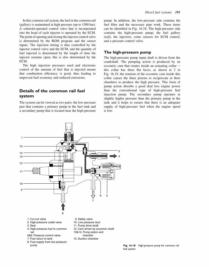
In this common rail system, the fuel in the common rail(gallery) is maintained at high pressure (up to 1500 bar).A solenoid-operated control valve that is incorporatedinto the head of each injector is operated by the ECM.Thepoint of opening and closing the injector control valveis determined by the ROM program and the sensorinputs. The injection timing is thus controlled by theinjector control valve and the ECM, and the quantity offuel injected is determined by the length of time theinjector remains open; this is also determined by theECM.
The high injection pressures used and electroniccontrol of the amount of fuel that is injected meansthat combustion efficiency is good, thus leading toimproved fuel economy and reduced emissions.
Details of the common rail fuelsystem
The system can be viewed as two parts: the low-pressurepart that contains a primary pump in the fuel tank anda secondary pump that is located near the high-pressure
pump. In addition, the low-pressure side contains thefuel filter and the necessary pipe work. These itemscan be identified in Fig. 16.18. The high-pressure sidecontains the high-pressure pump, the fuel gallery(rail), the injectors, some sensors for ECM control,and a pressure control valve.
The high-pressure pump
The high-pressure pump input shaft is driven from thecrankshaft. The pumping action is produced by aneccentric cam that rotates inside an actuating collar ethis collar has three flat faces; as shown at 2 inFig. 16.19, the rotation of the eccentric cam inside thiscollar causes the three pistons to reciprocate in theirchambers to produce the high pressure. This form ofpump action absorbs a good deal less engine powerthan the conventional type of high-pressure fuelinjection pump. The secondary pump operates atslightly higher pressure than the primary pump in thetank and it helps to ensure that there is an adequatesupply of high-pressure fuel when the engine speedis low.
1. Cut out valve2. High-pressure outlet valve3. Seal4. High-pressure fuel to common rail5&6. Pressure control valve7. Fuel return to tank8. Fuel supply from low pressure pump
9. Safety valve10. Low pressure duct11. Pump drive shaft12. Cam driven by eccentric shaft13&14. Pump piston and chamber15. Suction chamber
7
6 5
8
9
10
11
12
1314
15
1
4
3
2
Fig. 16.18 High-pressure pump for common rail
fuel system
Diesel fuel systems 191
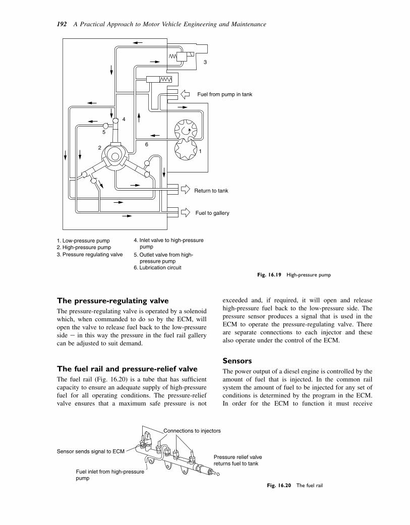
The pressure-regulating valve
The pressure-regulating valve is operated by a solenoidwhich, when commanded to do so by the ECM, willopen the valve to release fuel back to the low-pressureside e in this way the pressure in the fuel rail gallerycan be adjusted to suit demand.
The fuel rail and pressure-relief valve
The fuel rail (Fig. 16.20) is a tube that has sufficientcapacity to ensure an adequate supply of high-pressurefuel for all operating conditions. The pressure-reliefvalve ensures that a maximum safe pressure is not
exceeded and, if required, it will open and releasehigh-pressure fuel back to the low-pressure side. Thepressure sensor produces a signal that is used in theECM to operate the pressure-regulating valve. Thereare separate connections to each injector and thesealso operate under the control of the ECM.
Sensors
The power output of a diesel engine is controlled by theamount of fuel that is injected. In the common railsystem the amount of fuel to be injected for any set ofconditions is determined by the program in the ECM.In order for the ECM to function it must receive
Fuel from pump in tank
3
Return to tank
Fuel to gallery
1. Low-pressure pump2. High-pressure pump3. Pressure regulating valve
4. Inlet valve to high-pressure pump
5. Outlet valve from high- pressure pump6. Lubrication circuit
16
4
5
2
Fig. 16.19 High-pressure pump
Connections to injectors
Sensor sends signal to ECM
Fuel inlet from high-pressurepump
Pressure relief valvereturns fuel to tank
Fig. 16.20 The fuel rail
192 A Practical Approach to Motor Vehicle Engineering and Maintenance
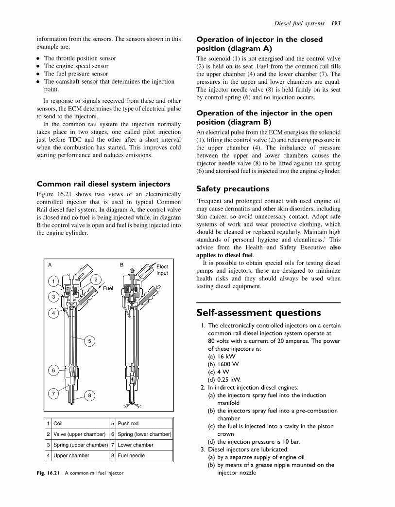
information from the sensors. The sensors shown in thisexample are:
� The throttle position sensor� The engine speed sensor� The fuel pressure sensor� The camshaft sensor that determines the injection
point.
In response to signals received from these and othersensors, the ECM determines the type of electrical pulseto send to the injectors.
In the common rail system the injection normallytakes place in two stages, one called pilot injectionjust before TDC and the other after a short intervalwhen the combustion has started. This improves coldstarting performance and reduces emissions.
Common rail diesel system injectors
Figure 16.21 shows two views of an electronicallycontrolled injector that is used in typical CommonRail diesel fuel system. In diagram A, the control valveis closed and no fuel is being injected while, in diagramB the control valve is open and fuel is being injected intothe engine cylinder.
Operation of injector in the closedposition (diagram A)
The solenoid (1) is not energised and the control valve(2) is held on its seat. Fuel from the common rail fillsthe upper chamber (4) and the lower chamber (7). Thepressures in the upper and lower chambers are equal.The injector needle valve (8) is held firmly on its seatby control spring (6) and no injection occurs.
Operation of the injector in the openposition (diagram B)
An electrical pulse from the ECM energises the solenoid(1), lifting the control valve (2) and releasing pressure inthe upper chamber (4). The imbalance of pressurebetween the upper and lower chambers causes theinjector needle valve (8) to be lifted against the spring(6) and atomised fuel is injected into the engine cylinder.
Safety precautions
‘Frequent and prolonged contact with used engine oilmay cause dermatitis and other skin disorders, includingskin cancer, so avoid unnecessary contact. Adopt safesystems of work and wear protective clothing, whichshould be cleaned or replaced regularly. Maintain highstandards of personal hygiene and cleanliness.’ Thisadvice from the Health and Safety Executive alsoapplies to diesel fuel.
It is possible to obtain special oils for testing dieselpumps and injectors; these are designed to minimizehealth risks and they should always be used whentesting diesel equipment.
Self-assessment questions1. The electronically controlled injectors on a certain
common rail diesel injection system operate at80 volts with a current of 20 amperes. The powerof these injectors is:(a) 16 kW(b) 1600 W(c) 4 W(d) 0.25 kW.
2. In indirect injection diesel engines:(a) the injectors spray fuel into the induction
manifold(b) the injectors spray fuel into a pre-combustion
chamber(c) the fuel is injected into a cavity in the piston
crown(d) the injection pressure is 10 bar.
3. Diesel injectors are lubricated:(a) by a separate supply of engine oil(b) by means of a grease nipple mounted on the
injector nozzle
1 2
3
4
5
6
7 8
Fuel
ElectInput
BA
Coil
Valve (upper chamber)
Spring (upper chamber)
Upper chamber
Spring (lower chamber)
Lower chamber
Push rod
Fuel needle
1
2
3
4
5
6
7
8
Fig. 16.21 A common rail fuel injector
Diesel fuel systems 193
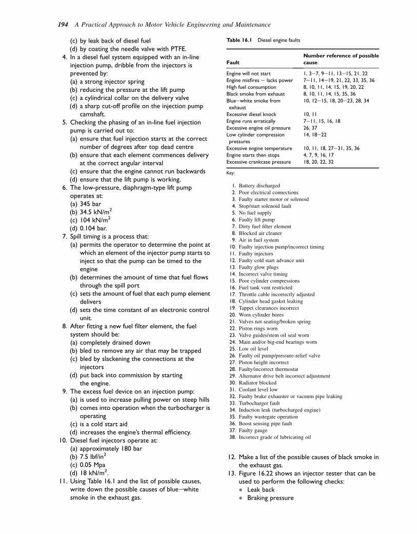
(c) by leak back of diesel fuel(d) by coating the needle valve with PTFE.
4. In a diesel fuel system equipped with an in-lineinjection pump, dribble from the injectors isprevented by:(a) a strong injector spring(b) reducing the pressure at the lift pump(c) a cylindrical collar on the delivery valve(d) a sharp cut-off profile on the injection pump
camshaft.5. Checking the phasing of an in-line fuel injection
pump is carried out to:(a) ensure that fuel injection starts at the correct
number of degrees after top dead centre(b) ensure that each element commences delivery
at the correct angular interval(c) ensure that the engine cannot run backwards(d) ensure that the lift pump is working.
6. The low-pressure, diaphragm-type lift pumpoperates at:(a) 345 bar(b) 34.5 kN/m2
(c) 104 kN/m2
(d) 0.104 bar.7. Spill timing is a process that:
(a) permits the operator to determine the point atwhich an element of the injector pump starts toinject so that the pump can be timed to theengine
(b) determines the amount of time that fuel flowsthrough the spill port
(c) sets the amount of fuel that each pump elementdelivers
(d) sets the time constant of an electronic controlunit.
8. After fitting a new fuel filter element, the fuelsystem should be:(a) completely drained down(b) bled to remove any air that may be trapped(c) bled by slackening the connections at the
injectors(d) put back into commission by starting
the engine.9. The excess fuel device on an injection pump:
(a) is used to increase pulling power on steep hills(b) comes into operation when the turbocharger is
operating(c) is a cold start aid(d) increases the engine’s thermal efficiency.
10. Diesel fuel injectors operate at:(a) approximately 180 bar(b) 7.5 lbf/in2
(c) 0.05 Mpa(d) 18 kN/m2.
11. Using Table 16.1 and the list of possible causes,write down the possible causes of blueewhitesmoke in the exhaust gas.
12. Make a list of the possible causes of black smoke inthe exhaust gas.
13. Figure 16.22 shows an injector tester that can beused to perform the following checks:� Leak back� Braking pressure
Table 16.1 Diesel engine faults
Fault
Number reference of possible
cause
Engine will not start 1, 3e7, 9e11, 13e15, 21, 22Engine misfires e lacks power 7e11, 14e19, 21, 22, 33, 35, 36
High fuel consumption 8, 10, 11, 14, 15, 19, 20, 22
Black smoke from exhaust 8, 10, 11, 14, 15, 35, 36
Blueewhite smoke from
exhaust
10, 12e15, 18, 20e23, 28, 34
Excessive diesel knock 10, 11
Engine runs erratically 7e11, 15, 16, 18
Excessive engine oil pressure 26, 37
Low cylinder compression
pressures
14, 18e22
Excessive engine temperature 10, 11, 18, 27e31, 35, 36
Engine starts then stops 4, 7, 9, 16, 17
Excessive crankcase pressure 18, 20, 22, 32
Key:
1. Battery discharged
2. Poor electrical connections
3. Faulty starter motor or solenoid
4. Stop/start solenoid fault
5. No fuel supply
6. Faulty lift pump
7. Dirty fuel filter element
8. Blocked air cleaner
9. Air in fuel system
10. Faulty injection pump/incorrect timing
11. Faulty injectors
12. Faulty cold start advance unit
13. Faulty glow plugs
14. Incorrect valve timing
15. Poor cylinder compressions
16. Fuel tank vent restricted
17. Throttle cable incorrectly adjusted
18. Cylinder head gasket leaking
19. Tappet clearances incorrect
20. Worn cylinder bores
21. Valves not seating/broken spring
22. Piston rings worn
23. Valve guides/stem oil seal worn
24. Main and/or big-end bearings worn
25. Low oil level
26. Faulty oil pump/pressure-relief valve
27. Piston height incorrect
28. Faulty/incorrect thermostat
29. Alternator drive belt incorrect adjustment
30. Radiator blocked
31. Coolant level low
32. Faulty brake exhauster or vacuum pipe leaking
33. Turbocharger fault
34. Induction leak (turbocharged engine)
35. Faulty wastegate operation
36. Boost sensing pipe fault
37. Faulty gauge
38. Incorrect grade of lubricating oil
194 A Practical Approach to Motor Vehicle Engineering and Maintenance
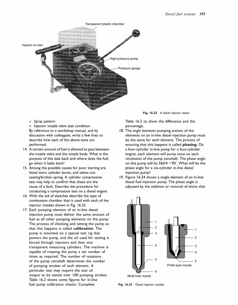
� Spray pattern� Injector nozzle valve seat condition.By reference to a workshop manual, and bydiscussion with colleagues, write a few lines todescribe how each of the above tests areperformed.
14. A certain amount of fuel is allowed to pass betweenthe nozzle valve and the nozzle body. What is thepurpose of this leak back and where does the fuelgo when it leaks back?
15. Among the possible causes for poor starting arelisted worn cylinder bores, and valves notseating/broken spring. A cylinder compressiontest may help to confirm that these are thecause of a fault. Describe the procedure forconducting a compression test on a diesel engine.
16. With the aid of sketches describe the type ofcombustion chamber that is used with each of theinjector nozzles shown in Fig. 16.23.
17. Each pumping element of an in-line dieselinjection pump must deliver the same amount offuel as all other pumping elements on the pump.The process of checking and setting the pump sothat this happens is called calibration. Thepump is mounted on a special test rig thatpowers the pump, and the oil used for testing isforced through injectors and then intotransparent measuring cylinders. The machine iscapable of rotating the pump a set number oftimes as required. The number of rotationsof the pump camshaft determines the numberof pumping strokes of each element. Aparticular test may require the test oiloutput to be tested over 100 pumping strokes.Table 16.2 shows some figures for in-linefuel pump calibration checks. Complete
Table 16.2 to show the difference and thepercentage.
18. The angle between pumping actions of theelements on an in-line diesel injection pump mustbe the same for each element. The process ofensuring that this happens is called phasing. Ona four-cylinder in-line pump for a four-cylinderengine, each element will pump once on eachrevolution of the pump camshaft. The phase angleon this pump will be 360/4 5908. What will be thephase angle for a six-cylinder in-line dieselinjection pump?
19. Figure 16.24 shows a single element of an in-linediesel fuel injection pump. The phase angle isadjusted by the addition or removal of shims that
Transparent plastic chamber
High-pressure pump
Pressure gauge
Injector on test
Fig. 16.22 A diesel injector tester
1
2
3
4
5
1
2
3
4
5Pintle type nozzle
Multi-hole nozzle6
Fig. 16.23 Diesel injector nozzles
Diesel fuel systems 195
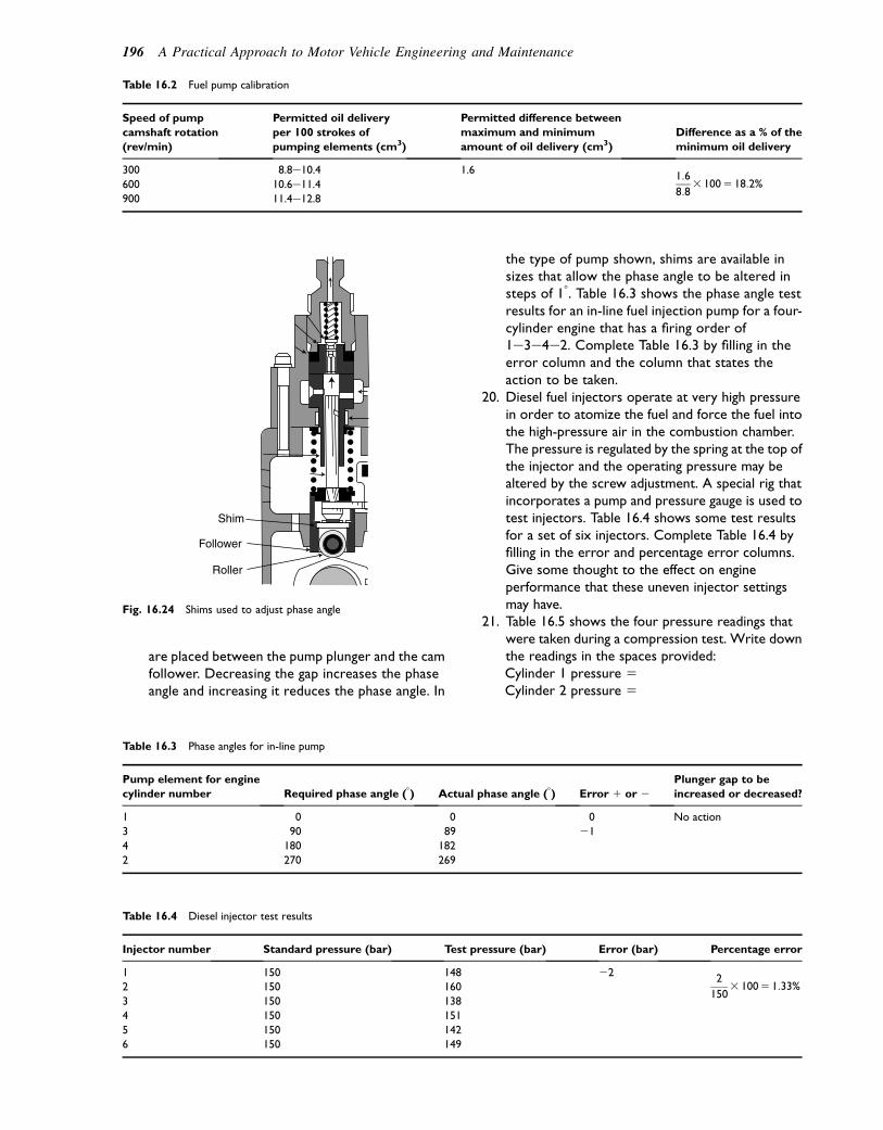
are placed between the pump plunger and the camfollower. Decreasing the gap increases the phaseangle and increasing it reduces the phase angle. In
the type of pump shown, shims are available insizes that allow the phase angle to be altered insteps of 18. Table 16.3 shows the phase angle testresults for an in-line fuel injection pump for a four-cylinder engine that has a firing order of1e3e4e2. Complete Table 16.3 by filling in theerror column and the column that states theaction to be taken.
20. Diesel fuel injectors operate at very high pressurein order to atomize the fuel and force the fuel intothe high-pressure air in the combustion chamber.The pressure is regulated by the spring at the top ofthe injector and the operating pressure may bealtered by the screw adjustment. A special rig thatincorporates a pump and pressure gauge is used totest injectors. Table 16.4 shows some test resultsfor a set of six injectors. Complete Table 16.4 byfilling in the error and percentage error columns.Give some thought to the effect on engineperformance that these uneven injector settingsmay have.
21. Table 16.5 shows the four pressure readings thatwere taken during a compression test. Write downthe readings in the spaces provided:Cylinder 1 pressure 5Cylinder 2 pressure 5
Table 16.2 Fuel pump calibration
Speed of pump
camshaft rotation
(rev/min)
Permitted oil delivery
per 100 strokes of
pumping elements (cm3)
Permitted difference between
maximum and minimum
amount of oil delivery (cm3)
Difference as a % of the
minimum oil delivery
300 8.8e10.4 1.61:6
8:83 1005 18:2%600 10.6e11.4
900 11.4e12.8
Shim
Follower
Roller
Fig. 16.24 Shims used to adjust phase angle
Table 16.3 Phase angles for in-line pump
Pump element for engine
cylinder number Required phase angle (8) Actual phase angle (8) Error 1 or 2Plunger gap to be
increased or decreased?
1 0 0 0 No action
3 90 89 21
4 180 182
2 270 269
Table 16.4 Diesel injector test results
Injector number Standard pressure (bar) Test pressure (bar) Error (bar) Percentage error
1 150 148 222
1503 1005 1:33%2 150 160
3 150 138
4 150 151
5 150 142
6 150 149
196 A Practical Approach to Motor Vehicle Engineering and Maintenance
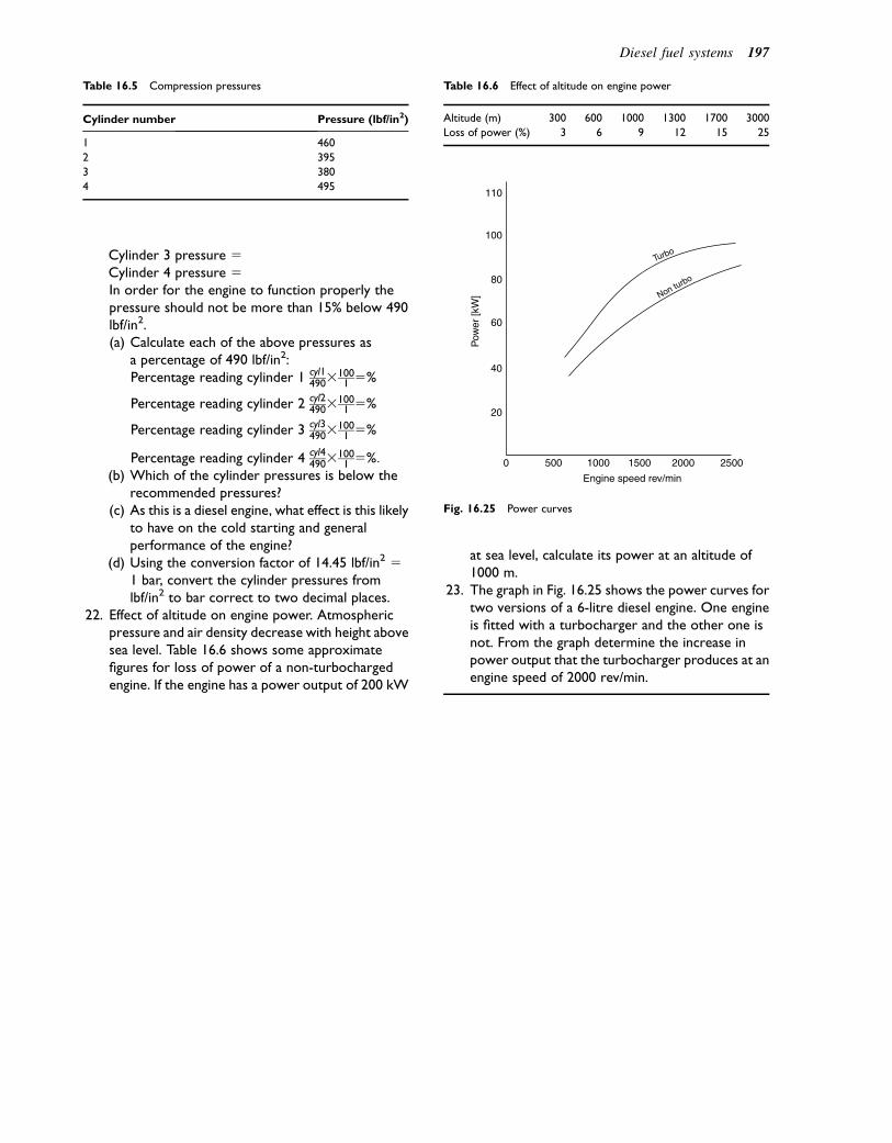
Cylinder 3 pressure 5Cylinder 4 pressure 5In order for the engine to function properly thepressure should not be more than 15% below 490lbf/in2.(a) Calculate each of the above pressures as
a percentage of 490 lbf/in2:Percentage reading cylinder 1 cyl1
49031001 5%
Percentage reading cylinder 2 cyl24903
1001 5%
Percentage reading cylinder 3 cyl34903
1001 5%
Percentage reading cylinder 4 cyl44903
1001 5%:
(b) Which of the cylinder pressures is below therecommended pressures?
(c) As this is a diesel engine, what effect is this likelyto have on the cold starting and generalperformance of the engine?
(d) Using the conversion factor of 14.45 lbf/in2 51 bar, convert the cylinder pressures fromlbf/in2 to bar correct to two decimal places.
22. Effect of altitude on engine power. Atmosphericpressure and air density decrease with height abovesea level. Table 16.6 shows some approximatefigures for loss of power of a non-turbochargedengine. If the engine has a power output of 200 kW
at sea level, calculate its power at an altitude of1000 m.
23. The graph in Fig. 16.25 shows the power curves fortwo versions of a 6-litre diesel engine. One engineis fitted with a turbocharger and the other one isnot. From the graph determine the increase inpower output that the turbocharger produces at anengine speed of 2000 rev/min.
Table 16.5 Compression pressures
Cylinder number Pressure (lbf/in2)
1 460
2 395
3 380
4 495
Table 16.6 Effect of altitude on engine power
Altitude (m) 300 600 1000 1300 1700 3000
Loss of power (%) 3 6 9 12 15 25
0
20
40
Non turbo
Turbo
60
80
100
110
500 1000
Engine speed rev/minP
ower
[kW
]1500 2000 2500
Fig. 16.25 Power curves
Diesel fuel systems 197
17Engine fault diagnosis
Topics covered in thischapter
Detailed examination of some examples of enginefailuresSystematic approaches to fault diagnosis
Engine faults
The in-depth consideration of two typical automotivefailures in this chapter is designed to demonstrate prin-ciples of automotive fault tracing and rectification.
In order for an internal combustion engine to work itmust:
1. Be in good mechanical condition2. Have a fuel and air system3. Have a means of igniting the fuel e the ignition
system4. Have a means of disposing of exhaust products e the
exhaust system.
This chapter deals with the first of these; otherchapters deal with the points 2e4.
Mechanical condition
Engine components
In normal use, all of the mechanical components shownin Fig. 17.1 wear and in time this causes them to cease tofunction as intended. Careful routine maintenance keepswear to a minimum, but eventually the wear of compo-nents will cause a lowering of performance and repairswill be needed to bring the engine or other unit back toits original performance level. Faults may also occurthrough misuse, failure to maintain, and defects inmanufacture or materials.
Whilst accepting that almost any mechanical compo-nent may fail, it is not reasonable to expect to coverevery possible contingency. However, by examininga number of examples it is possible to see that there is
a procedure that is applicable to all fault diagnosis ofautomotive systems and that this procedure comprisessix steps:
1. Collect evidence2. Analyse the evidence3. Locate the fault4. Find the cause of the fault5. Rectify the fault6. Thoroughly test the system.
I propose to show how this six-step procedure appliesto fault diagnosis by examining a number of examples.
Example 17.1. Cylinder head gasketfailure (Fig. 17.2)
Step 1. Collect the evidence
What are the symptoms? They could be one or more ofthe following:
� Engine malfunction indicator light (MIL)� Loss of power� Difficulty in starting the engine� Blow back into the intake system� Defective emissions control.
How did the technician find out about the symptoms?
� Report from the driver� Detected during other work on the vehicle.
Step 2. Analyse the evidence
Assuming that the driver has reported the problem it willbe necessary to discuss the details with her/him. Somedrivers will deal with this better than others and a techni-cian should always be aware that this an area of informa-tion about faults that can be of considerable value. Anassessment of the different types of customer that anautomotive technician may expect to encounter is givenin the Introduction.
A check sheet on which to make notes is a useful aidthat can help when deciding how to deal with thedefective vehicle.
� 2011 Allan Bonnick and Derek Newbold. Published by Elsevier Ltd. All rights reserved
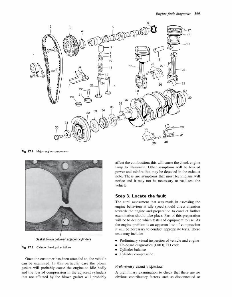
Once the customer has been attended to, the vehiclecan be examined. In this particular case the blowngasket will probably cause the engine to idle badlyand the loss of compression in the adjacent cylindersthat are affected by the blown gasket will probably
affect the combustion; this will cause the check enginelamp to illuminate. Other symptoms will be loss ofpower and misfire that may be detected in the exhaustnote. These are symptoms that most technicians willnotice and it may not be necessary to road test thevehicle.
Step 3. Locate the fault
The aural assessment that was made in assessing theengine behaviour at idle speed should direct attentiontowards the engine and preparation to conduct furtherexamination should take place. Part of this preparationwill be to decide which tests and equipment to use. Asthe engine problem is an apparent loss of compressionit will be necessary to conduct appropriate tests. Thesetests may include:
� Preliminary visual inspection of vehicle and engine� On-board diagnostics (OBD), PO code� Cylinder balance� Cylinder compression.
Preliminary visual inspection
A preliminary examination to check that there are noobvious contributory factors such as disconnected or
56
7
89
10
11
12
17
18
19
1
2 34
2021
2223
24
13
14
25
26
25
26
27
16
1528
29
30
31
32 33 3435
3637
38
39
40
29
41
Fig. 17.1 Major engine components
Gasket blown between adjacent cylinders
Fig. 17.2 Cylinder head gasket failure
Engine fault diagnosis 199

damaged cables and other components is a useful firststep. It also helps to ascertain general vehicle condition,which may be a factor to consider when the vehicle isreturned to the owner after repairs have been completed.
On-board diagnostics
If the engine check lamp is illuminated some fault codeswill be available. These codes are called diagnostictrouble codes (DTCs) and they are downloaded toa code reader through the diagnostic port that is nor-mally located in a readily accessible place near theinstrument panel. Details of fault code readers and scan-ners are given in the section that deals with tools andequipment. At the moment it is sufficient to considerwhat the DTCs may tell us.
As we are probably dealing with an emissions-relatedfault, the DTC will be in the form of an EOBD or OBD2code similar to these examples:
� PO 302 e cylinder 2 misfire detected� PO 303 e cylinder 3 misfire detected.
This indicates a problem in cylinders 2 and 3 which, ina four-cylinder in-line engine, are adjacent to each other.
Cylinder balance test
The cylinder balance test makes use of the fact thatcylinder pressure and sparking plug HT (high tension)voltage are related; low cylinder pressures producelower sparking voltages than cylinders that have higherpressure. The oscilloscope pattern in Fig. 17.3 showsthat the HT voltage in cylinders 2 and 3 is significantlylower than that in cylinders 1 and 4. This supports theinformation gathered from the DTCs and is furtherevidence that the fault is probably very low compressionin cylinders 2 and 3. A cylinder compression test willproduce further evidence to help locate the fault.
Cylinder compression test
A compression test (Fig. 17.4) is a useful method ofchecking engine condition. The spark plugs are firstremoved and the compression tester is inserted intothe spark plug hole in turn. Each cylinder is checkedand the figures recorded ready for examination. Theactual pressure reached varies according to the makeand type of engine; the workshop manual should bereferred to.
The type of result expected here is shown in Table17.1. The workshop manual shows that the cylinderpressure should be within 10% of 12.5 bar. Cylinderpressure in 2 and 3 is lower than this, which is furtherevidence that the fault is low compression in cylinders2 and 3.
This leads to the next step.
Step 4. Find the cause
At this stage it is necessary to consider possible causesof low compression (Table 17.2) and then, in the light of
TIME
Cylinder balance oscilloscope pattern.
3 4 2 1
0
10 kV
40 kV
30 kV
20 kV
Fig. 17.3 Cylinder balance test
Fig. 17.4 Petrol engine compression test
200 A Practical Approach to Motor Vehicle Engineering and Maintenance
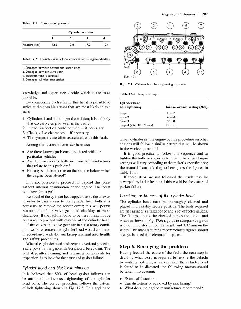
knowledge and experience, decide which is the mostprobable.
By considering each item in this list it is possible toarrive at the possible causes that are most likely in thiscase:
1. Cylinders 1 and 4 are in good condition; it is unlikelythat excessive engine wear is the cause.
2. Further inspection could be used e if necessary.3. Check valve clearances e if necessary.4. The symptoms are often associated with this fault.
Among the factors to consider here are:
� Are there known problems associated with theparticular vehicle?
� Are there any service bulletins from the manufacturerthat relate to this problem?
� Has any work been done on the vehicle before e hasthe engine been altered?
It is not possible to proceed far beyond this pointwithout internal examination of the engine. The pointis e how far to go?
Removal of the cylinder head appears to be the answer.In order to gain access to the cylinder head bolts it isnecessary to remove the rocker cover; this will permitexamination of the valve gear and checking of valveclearances. If the fault is found to be here it may not benecessary to proceed with removal of the cylinder head.
If the valves and valve gear are in satisfactory condi-tion, work to remove the cylinder head would continue,in accordance with the workshop manual and healthand safety procedures.
When the cylinder headhas been removedandplaced ina safe position the gasket defect should be evident. Thenext step, after cleaning and preparing components forinspection, is to look for the causes of gasket failure.
Cylinder head and block examination
It is believed that 80% of head gasket failures canbe attributed to incorrect tightening of the cylinderhead bolts. The correct procedure follows the patternof bolt tightening shown in Fig. 17.5. This applies to
a four-cylinder in-line engine but the procedure on otherengines will follow a similar pattern that will be shownin the workshop manual.
It is good practice to follow this sequence and totighten the bolts in stages as follows. The actual torquesettings will vary according to the maker’s specification;the manual I am referring to here gives the figures inTable 17.3.
If these steps are not followed the result may bea warped cylinder head and this could be the cause ofgasket failure.
Checking for flatness of the cylinder head
The cylinder head must be thoroughly cleaned andplaced in a suitably secure position. The tools requiredare an engineer’s straight edge and a set of feeler gauges.The flatness should be checked across the length andwidth as shown in Fig. 17.6; a guide to acceptable figuresis 0.06 mm distortion on the length and 0.02 mm on thewidth. The manufacturer’s recommended figures shouldalways be used for reference purposes.
Step 5. Rectifying the problem
Having located the cause of the fault, the next step isdeciding what work is required to restore the vehicleto working order. If, as an example, the cylinder headis found to be distorted, the following factors shouldbe taken into account:
� Extent of distortion� Can distortion be removed by machining?� What does the engine manufacturer recommend?
Table 17.1 Compression pressure
Cylinder number
1 2 3 4
Pressure (bar) 12.2 7.8 7.2 12.6
Table 17.2 Possible causes of low compression in engine cylinders‘
1. Damaged or worn pistons and piston rings
2. Damaged or worn valve gear
3. Incorrect valve clearances
4. Damaged cylinder head gasket
Fig. 17.5 Cylinder head bolt-tightening sequence
Table 17.3 Torque settings
Cylinder head
bolt tightening Torque wrench setting (Nm)
Stage 1 10e15
Stage 2 40e50Stage 3 80e90
Stage 4 (after 10e20 min) 100e110
Engine fault diagnosis 201

� Will removing metal from the head surface raise thecompression ratio?
� If machining is permissible, what thickness of metalcan be removed?
� How old is the vehicle e would a new cylinder headbe an option?
Table 17.4 lists other possible causes of gasket failure.The practical work required in automotive repair
involves many skills that are acquired during practicaltraininge they are important elements of successful faulttracing and rectification, and they are dealt with in appren-ticeships and other forms of on- and off-the-job training.
Step 6. Thoroughly test the system
The final step is to thoroughly test the system. In the caseofmajor enginework this would include a comprehensiveroad test and engine analysis to ensure that emissions arewithin legal limits. The engine would be examined toensure that there are no leaks of oil or engine coolant.When all is found to be satisfactory the vehicle shouldbe checked to make sure that the interior and exteriorare clean and ready to be returned to the customer.
Example 17.2. Bearing failure
According to the bearing manufacturer’s literature, thetype of bearing failure shown in Fig. 17.7 is often
caused by lubrication problems that lead to metal-to-metal contact, high friction, and wear. This suggeststhat lubrication system failures are the general area toexamine.
The examination in Example 17.1 shows that the six-step approach is a valuable procedure that lends itself tothe treatment of other faults and their diagnosis; this isthe approach that is used for this and other examplesin this book.
Step 1. Collect evidence
This is probably best done in stages:
1. Consult the customer.2. Perform aural and visual checks.3. Use a stethoscope to attempt to refine the evidence.4. Establish the conditions under which the knock is
most evident.5. Check to find out if the particular engine is prone to
the type of knock identified.
Step 2. Analyse the evidence
In order to deal with this step, I shall assume that thefault displays the following symptoms:
1. The oil warning lamp is slow to go out when theengine is first started and the knocking noise is loud.
IAS2105271
Fig. 17.6 Checking flatness of cylinder head
Table 17.4 Other possible causes of gasket failure
Possible cause Remedy
Wet cylinder liner unseated. The liner is not protruding enough to
allow the gasket to seat properly
Find cause and carry out repairs in accordance with the workshop
manual
Combustion problems. Detonation and pre-ignition cause high
temperatures and pressure in the combustion chamber.
Excessively high temperature can burn the gasket. Extremely high
local pressure offsets the bolt clamping force
Check ignition setting. Ensure that correct grade of fuel has been
used. Check to see if engine has been altered to raise compression
ratio
Material trapped between cylinder head or block and the gasket Make sure this does not happen on reassembly
202 A Practical Approach to Motor Vehicle Engineering and Maintenance
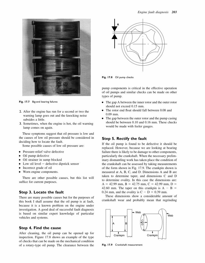
2. After the engine has run for a second or two thewarning lamp goes out and the knocking noisesubsides a little.
3. Sometimes, when the engine is hot, the oil warninglamp comes on again.
These symptoms suggest that oil pressure is low andthe causes of low oil pressure should be considered indeciding how to locate the fault.
Some possible causes of low oil pressure are:
� Pressure-relief valve defective� Oil pump defective� Oil strainer in sump blocked� Low oil level e defective dipstick sensor� Incorrect grade of oil� Worn engine components.
There are other possible causes, but this list willsuffice for current purposes.
Step 3. Locate the fault
There are many possible causes but for the purposes ofthis book I shall assume that the oil pump is at fault,because it is a known problem on the engine underinvestigation. A good deal of successful fault diagnosisis based on similar expert knowledge of particularvehicles and systems.
Step 4. Find the cause
After cleaning, the oil pump can be opened up forinspection. Figure 17.8 shows an example of the typeof checks that can be made on the mechanical conditionof a rotary-type oil pump. The clearance between the
pump components is critical in the effective operationof oil pumps and similar checks can be made on othertypes of pump.
� The gap A between the inner rotor and the outer rotorshould not exceed 0.15 mm.
� The rotor end float should fall between 0.08 and0.09 mm.
� The gap between the outer rotor and the pump casingshould be between 0.10 and 0.16 mm. These checkswould be made with feeler gauges.
Step 5. Rectify the fault
If the oil pump is found to be defective it should bereplaced. However, because we are looking at bearingfailure there is likely to be damage to other components,particularly the crankshaft. When the necessary prelim-inary dismantling work has taken place the condition ofthe crankshaft can be assessed by taking measurementsof the form shown in Fig. 17.9. The crankpin shown ismeasured at A, B, C, and D. Dimensions A and B aretaken to determine taper, and dimensions C and Dto determine ovality. In this case the dimensions are:A 5 42.99 mm, B 5 42.75 mm, C 5 42.99 mm, D 542.60 mm. The taper on this crankpin is A 2 B 50.24 mm, and the ovality is C 2 D 5 0.39 mm.
These dimensions show a considerable amount ofcrankshaft wear and probably mean that regrinding
Fig. 17.7 Big-end bearing failures
A
Fig. 17.8 Oil pump checks
A
Crankpin
BCD
Web
Crankpin
Web
Fig. 17.9 Crankshaft measurement
Engine fault diagnosis 203
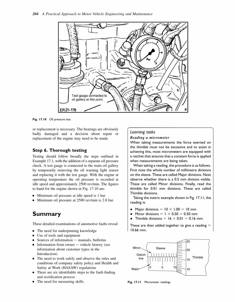
or replacement is necessary. The bearings are obviouslybadly damaged and a decision about repair orreplacement of the engine may need to be made.
Step 6. Thorough testing
Testing should follow broadly the steps outlined inExample 17.1, with the addition of a separate oil pressurecheck. A test gauge is connected to the main oil galleryby temporarily removing the oil warning light sensorand replacing it with the test gauge. With the engine atoperating temperature the oil pressure is recorded atidle speed and approximately 2500 rev/min. The figuresto hand for the engine shown in Fig. 17.10 are:
� Minimum oil pressure at idle speed is 1 bar� Minimum oil pressure at 2500 rev/min is 2.8 bar.
Summary
These detailed examinations of automotive faults reveal:
� The need for underpinning knowledge� Use of tools and equipment� Sources of information e manuals, bulletins� Information from owner e vehicle history (see
information about customer types in theIntroduction)
� The need to work safely and observe the rules andconditions of company safety policy and Health andSafety at Work (HASAW) regulations
� There are six identifiable steps to the fault-findingand rectification process
� The need for measuring skills.
Learning tasksReading a micrometer
When taking measurements the force exerted onthe thimble must not be excessive and to assist inachieving this, most micrometers are equipped witha ratchet that ensures that a constant force is appliedwhen measurements are being taken.When taking a reading, the procedure is as follows.
First note the whole number of millimetre divisionson the sleeve. These are called Major divisions. Nextobserve whether there is a 0.5 mm division visible.These are called Minor divisions. Finally, read thethimble for 0.01 mm divisions. These are calledThimble divisions.Taking the metric example shown in Fig. 17.11, the
reading is:
� Major divisions 5 10 3 1.00 5 10 mm� Minor divisions 5 1 3 0.50 5 0.50 mm� Thimble divisions 5 16 3 0.01 5 0.16 mm.
These are then added together to give a reading 510.66 mm.
Fig. 17.10 Oil pressure test
Minor
Major
Datumline
Sleeve
0 5 1010
Thimble15
20
25
Fig. 17.11 Micrometer readings
204 A Practical Approach to Motor Vehicle Engineering and Maintenance

Write down the four readings shown in Fig. 17.12.
Crankshaft end floatFigure 17.13 shows the procedure for checking theend float on a crankshaft. End thrust on a crankshaftoccurs when the clutch is operated and when thevehicle is operating on an incline. In the engineshown, the end thrust is taken by half-washers madefrom bronze faced with bearing metal. The thrustfaces are lubricated by a film of oil and a small gapbetween the thrust washers and the crankshaft isprovided so that the oil film can be maintained;additional gap is also required to allow for thermalexpansion.The following figures relate to the engine shown in
Fig. 17.13:
� Crankshaft. Permissible end float0.09e0.30 mm
� Thrust half-washer thickness:� Standard size 2.301e2.351 mm� Oversize size 2.491e2.541 mm.
If the end float is found to be greater than thepermitted figure, new thrust washers must be fittedto restore the end float to the correct figure.
Self-assessment questions1. Table 17.5 shows a set of compression figures for
a four-cylinder engine. The percentage difference inreadings should not be greater than 15% of themaximum pressure recorded. Calculate thepercentage difference between the pressure in
cylinder number 3 and the other three cylinders,and enter the values into the table. Make a list of thefactors that may be causing the low pressure incylinder number 4.
2. A four-cylinder in-line four-stroke engine hasa firing order of 1e3e4e2. What stroke is number2 cylinder on when number 3 cylinder is on powerstroke?
3. Describe the difference between the termsdetonation and pre-ignition in the context of engineperformance.
4. Figure 17.14 shows a dial test indicator (DTI) beingused to check wet cylinder liner protrusion abovethe cylinder block face. Why is this measurementimportant?
5. Sometimes people contemplate raising thecompression ratio of an engine to increase thepower output. Make a list of some of the factorsthat need to be taken into account whenconsidering such a major alteration to an engine.
6. Table 17.6 shows some torque wrench settings thatare given in lbf-ft. Complete the table by convertingthese settings to Nm. Use the conversion factor1 lbf-ft 5 1.36 Nm.
7. A customer contacts the garage because the checkengine lamp in their car is illuminated. Whenchecked the scan tool shows fault ‘PO301 eCylinder misfire cylinder number 1’. Make a list ofthe factors that may be causing the misfire.
8. Pressure gauges that are used for compressiontests require calibration from time to time toensure that they are working correctly. How shouldthis calibration take place in the context of garagework?
Datumline
Sleeve
55
1010
15
Thimble
(a)
Datumline
Sleeve
1510
2015
20
Thimble
(b)
Micrometer size 0–25 mm
Micrometer size 25–50 mm
Datumline
Sleeve
100
155
10
Thimble
(c)
Datumline
Sleeve
0
25
530
35
Thimble
(d)
Micrometer size 75–100 mm
Micrometer size 0–25 mm
Fig. 17.12 External micrometer readings
Engine fault diagnosis 205
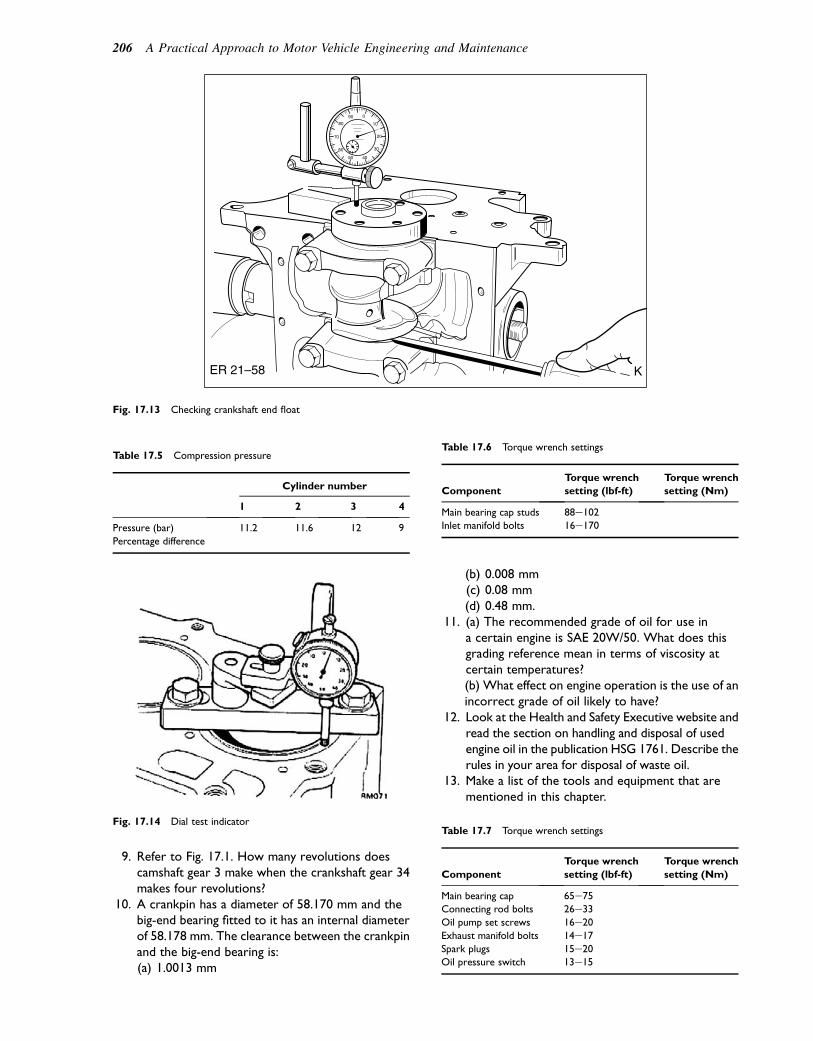
9. Refer to Fig. 17.1. How many revolutions doescamshaft gear 3 make when the crankshaft gear 34makes four revolutions?
10. A crankpin has a diameter of 58.170 mm and thebig-end bearing fitted to it has an internal diameterof 58.178 mm. The clearance between the crankpinand the big-end bearing is:(a) 1.0013 mm
(b) 0.008 mm(c) 0.08 mm(d) 0.48 mm.
11. (a) The recommended grade of oil for use ina certain engine is SAE 20W/50. What does thisgrading reference mean in terms of viscosity atcertain temperatures?(b) What effect on engine operation is the use of anincorrect grade of oil likely to have?
12. Look at the Health and Safety Executive website andread the section on handling and disposal of usedengine oil in the publication HSG 1761. Describe therules in your area for disposal of waste oil.
13. Make a list of the tools and equipment that arementioned in this chapter.
Table 17.5 Compression pressure
Cylinder number
1 2 3 4
Pressure (bar) 11.2 11.6 12 9
Percentage difference
KER 21–58
Fig. 17.13 Checking crankshaft end float
Fig. 17.14 Dial test indicator
Table 17.6 Torque wrench settings
Component
Torque wrench
setting (lbf-ft)
Torque wrench
setting (Nm)
Main bearing cap studs 88e102
Inlet manifold bolts 16e170
Table 17.7 Torque wrench settings
Component
Torque wrench
setting (lbf-ft)
Torque wrench
setting (Nm)
Main bearing cap 65e75Connecting rod bolts 26e33
Oil pump set screws 16e20
Exhaust manifold bolts 14e17
Spark plugs 15e20Oil pressure switch 13e15
206 A Practical Approach to Motor Vehicle Engineering and Maintenance
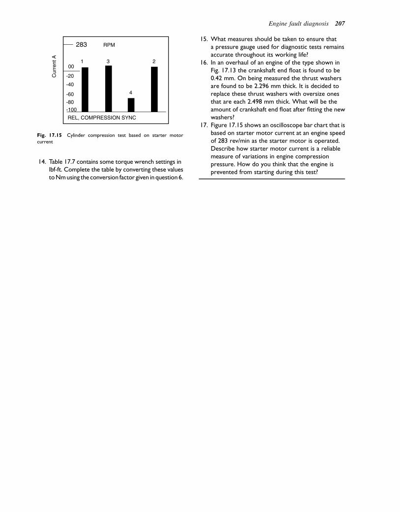
14. Table 17.7 contains some torque wrench settings inlbf-ft. Complete the table by converting these valuestoNmusing the conversion factor given inquestion6.
15. What measures should be taken to ensure thata pressure gauge used for diagnostic tests remainsaccurate throughout its working life?
16. In an overhaul of an engine of the type shown inFig. 17.13 the crankshaft end float is found to be0.42 mm. On being measured the thrust washersare found to be 2.296 mm thick. It is decided toreplace these thrust washers with oversize onesthat are each 2.498 mm thick. What will be theamount of crankshaft end float after fitting the newwashers?
17. Figure 17.15 shows an oscilloscope bar chart that isbased on starter motor current at an engine speedof 283 rev/min as the starter motor is operated.Describe how starter motor current is a reliablemeasure of variations in engine compressionpressure. How do you think that the engine isprevented from starting during this test?
Cur
rent
A
283 RPM
1 300
-20
-40
-60
-80-100
REL, COMPRESSION SYNC
4
2
Fig. 17.15 Cylinder compression test based on starter motor
current
Engine fault diagnosis 207
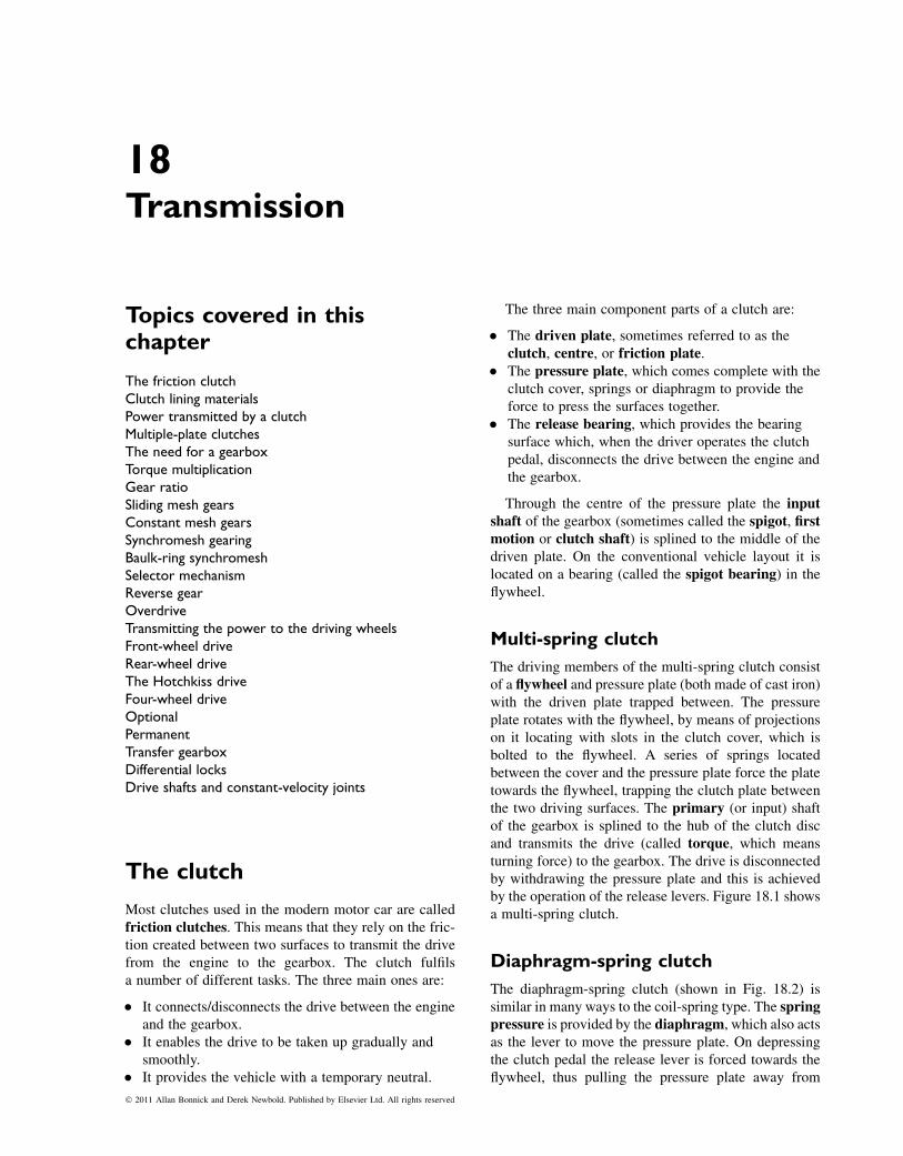
18Transmission
Topics covered in thischapter
The friction clutchClutch lining materialsPower transmitted by a clutchMultiple-plate clutchesThe need for a gearboxTorque multiplicationGear ratioSliding mesh gearsConstant mesh gearsSynchromesh gearingBaulk-ring synchromeshSelector mechanismReverse gearOverdriveTransmitting the power to the driving wheelsFront-wheel driveRear-wheel driveThe Hotchkiss driveFour-wheel driveOptionalPermanentTransfer gearboxDifferential locksDrive shafts and constant-velocity joints
The clutch
Most clutches used in the modern motor car are calledfriction clutches. This means that they rely on the fric-tion created between two surfaces to transmit the drivefrom the engine to the gearbox. The clutch fulfilsa number of different tasks. The three main ones are:
� It connects/disconnects the drive between the engineand the gearbox.
� It enables the drive to be taken up gradually andsmoothly.
� It provides the vehicle with a temporary neutral.
The three main component parts of a clutch are:
� The driven plate, sometimes referred to as theclutch, centre, or friction plate.
� The pressure plate, which comes complete with theclutch cover, springs or diaphragm to provide theforce to press the surfaces together.
� The release bearing, which provides the bearingsurface which, when the driver operates the clutchpedal, disconnects the drive between the engine andthe gearbox.
Through the centre of the pressure plate the inputshaft of the gearbox (sometimes called the spigot, firstmotion or clutch shaft) is splined to the middle of thedriven plate. On the conventional vehicle layout it islocated on a bearing (called the spigot bearing) in theflywheel.
Multi-spring clutch
The driving members of the multi-spring clutch consistof a flywheel and pressure plate (both made of cast iron)with the driven plate trapped between. The pressureplate rotates with the flywheel, by means of projectionson it locating with slots in the clutch cover, which isbolted to the flywheel. A series of springs locatedbetween the cover and the pressure plate force the platetowards the flywheel, trapping the clutch plate betweenthe two driving surfaces. The primary (or input) shaftof the gearbox is splined to the hub of the clutch discand transmits the drive (called torque, which meansturning force) to the gearbox. The drive is disconnectedby withdrawing the pressure plate and this is achievedby the operation of the release levers. Figure 18.1 showsa multi-spring clutch.
Diaphragm-spring clutch
The diaphragm-spring clutch (shown in Fig. 18.2) issimilar in many ways to the coil-spring type. The springpressure is provided by the diaphragm, which also actsas the lever to move the pressure plate. On depressingthe clutch pedal the release lever is forced towards theflywheel, thus pulling the pressure plate away from
� 2011 Allan Bonnick and Derek Newbold. Published by Elsevier Ltd. All rights reserved
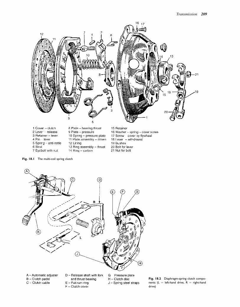
Fig. 18.1 The multi-coil spring clutch
Fig. 18.2 Diaphragm-spring clutch compo-
nents (L ¼ left-hand drive, R ¼ right-hand
drive)
Transmission 209
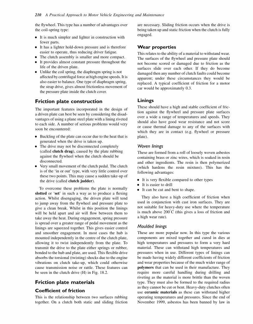
the flywheel. This type has a number of advantages overthe coil-spring type:
� It is much simpler and lighter in construction withfewer parts.
� It has a lighter hold-down pressure and is thereforeeasier to operate, thus reducing driver fatigue.
� The clutch assembly is smaller and more compact.� It provides almost constant pressure throughout the
life of the driven plate.� Unlike the coil spring, the diaphragm spring is not
affected by centrifugal force at high engine speeds. It isalso easier to balance. One type of diaphragm spring,the strap drive, gives almost frictionless movement ofthe pressure plate inside the clutch cover.
Friction plate construction
The important features incorporated in the design ofa driven plate can best be seen by considering the disad-vantages of using a plane steel plate with a lining rivetedto each side. A number of serious problems would verysoon be encountered:
� Buckling of the plate can occur due to the heat that isgenerated when the drive is taken up.
� The drive may not be disconnected completely(called clutch drag), caused by the plate rubbingagainst the flywheel when the clutch should bedisconnected.
� Very small movement of the clutch pedal. The clutchis of the ‘in or out’ type, with very little control overthese two points. This may cause a sudden take-up ofthe drive (called clutch judder).
To overcome these problems the plate is normallyslotted or ‘set’ in such a way as to produce a flexingaction. Whilst disengaging, the driven plate will tendto jump away from the flywheel and pressure plate togive a clean break. Whilst in this position the liningswill be held apart and air will flow between them totake away the heat. During engagement, spring pressureis spread over a greater range of pedal movement as thelinings are squeezed together. This gives easier controland smoother engagement. In most cases the hub ismounted independently in the centre of the clutch plate,allowing it to twist independently from the plate. Totransmit the drive to the plate either springs or rubber,bonded to the hub and plate, are used. This flexible driveabsorbs the torsional (twisting) shocks due to the enginevibrations on clutch take-up, which could otherwisecause transmission noise or rattle. These features canbe seen in the clutch drive (H) in Fig. 18.2.
Friction plate materials
Coefficient of friction
This is the relationship between two surfaces rubbingtogether. On a clutch both static and sliding friction
are necessary. Sliding friction occurs when the drive isbeing taken up and static friction when the clutch is fullyengaged.
Wear properties
This relates to the ability of a material to withstand wear.The surfaces of the flywheel and pressure plate shouldnot become scored or damaged due to friction as thesurfaces slide over each other. If they do becomedamaged then any number of clutch faults could becomeapparent; under these circumstances they would bereplaced. A typical coefficient of friction for a motorcar would be approximately 0.3.
Linings
These should have a high and stable coefficient of fric-tion against the flywheel and pressure plate surfacesover a wide a range of temperatures and speeds. Theyshould also have good wear resistance and not scoreor cause thermal damage to any of the surfaces withwhich they are in contact (e.g. flywheel or pressureplate).
Woven linings
These are formed from a roll of loosely woven asbestoscontaining brass or zinc wires, which is soaked in resinand other ingredients. The resin is then polymerized(which hardens the resin mixture). This has thefollowing advantages:
� It is very flexible compared to other types� It is easier to drill� It can be cut and bent to shape.
They also have a high coefficient of friction whenused in conjunction with cast iron surfaces. They arenot suitable for heavy-duty use where the temperatureis much above 2008C (this gives a loss of friction anda high wear rate).
Moulded linings
These are more popular now. In this type the variouscomponents are mixed together and cured in dies athigh temperatures and pressures to form a very hardmaterial. These can withstand high temperatures andpressures when in use. Different types of linings canbe made having widely different coefficients of frictionand wear properties because of the much wider range ofpolymers that can be used in their manufacture. Theyrequire more careful handling during drilling andriveting as the material is more brittle than the woventype. They must also be formed to the required radiusas they cannot be cut or bent. Heavy-duty clutches oftenuse ceramic materials as these can withstand higheroperating temperatures and pressures. Since the end ofNovember 1999, asbestos has been banned by law in
210 A Practical Approach to Motor Vehicle Engineering and Maintenance

the manufacture of new clutch linings (refer to thesection on Health and Safety in the Introduction).
Modern clutch lining materials
The use of asbestos in vehicle brake, clutch, and gasketcomponents has been prohibited since 1999, with theexception that pre-1973 vehicles could continue to befitted with asbestos-containing brake shoes until theend of 2004. It is possible that some old vehiclescould contain asbestos and sensible precautions shouldbe observed when working on such vehicles. Butremember that all brake and clutch dust is potentiallyharmful, so:
� Never blow dust out of brake drums or clutchhousings with an air line
� Use properly designed brake-cleaning equipmentthat prevents dust escaping
� Use clean, wet rags to clean out drums or housingsand dispose of used rags in a plastic waste bag (HSE).
Operating mechanisms
The clutch release bearing is fitted to the clutch releasefork. When the clutch pedal is pressed down by thedriver, pressure is exerted against the diaphragm springfingers by the release bearing forcing them towards theflywheel; this action disengages the drive from theengine.
The pedal linkage may be either mechanical orhydraulic. It must be flexibly mounted as the engine(which is mounted on rubbers) may move independentlyof the body/chassis.
Hydraulic linkage
In this arrangement, shown in Fig. 18.3, oil is displacedby the movement of the piston in themaster cylinder tothe slave cylinder to operate the release fork. The reser-voir on the master cylinder tops up the system as wear inthe clutch takes place.
Another form of hydraulic clutch release mechanismis shown in Fig. 18.4. This system dispenses with leversat the gearbox end because the annular slave cylinderapplies direct axial pressure to the release bearing.
Mechanical linkage
This operates on the principle of levers and rods orcable. The movement ratio and force ratio can bearranged to give a large force acting on the clutch,with a small force acting on the pedal. Figures 18.2and 18.5 show this system.
Adjustment
Adjustment of the hydraulic operating mechanism isautomatic. As wear of the linings takes place, the pistonin the slave cylinder takes up that amount of wear.
Fig. 18.3 The hydraulic clutch release mechanism. (a) Position of spring in the off (rest) position. (b) Position of spring with pedal depressed
Transmission 211
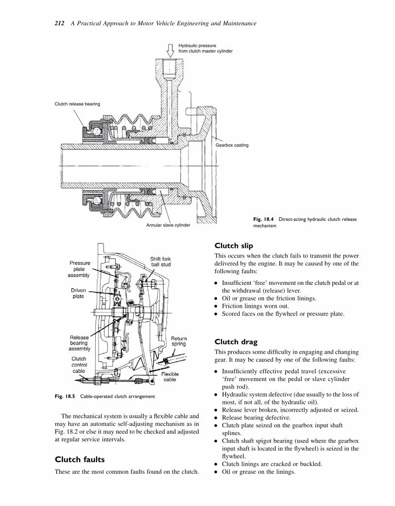
The mechanical system is usually a flexible cable andmay have an automatic self-adjusting mechanism as inFig. 18.2 or else it may need to be checked and adjustedat regular service intervals.
Clutch faults
These are the most common faults found on the clutch.
Clutch slip
This occurs when the clutch fails to transmit the powerdelivered by the engine. It may be caused by one of thefollowing faults:
� Insufficient ‘free’ movement on the clutch pedal or atthe withdrawal (release) lever.
� Oil or grease on the friction linings.� Friction linings worn out.� Scored faces on the flywheel or pressure plate.
Clutch drag
This produces some difficulty in engaging and changinggear. It may be caused by one of the following faults:
� Insufficiently effective pedal travel (excessive‘free’ movement on the pedal or slave cylinderpush rod).
� Hydraulic system defective (due usually to the loss ofmost, if not all, of the hydraulic oil).
� Release lever broken, incorrectly adjusted or seized.� Release bearing defective.� Clutch plate seized on the gearbox input shaft
splines.� Clutch shaft spigot bearing (used where the gearbox
input shaft is located in the flywheel) is seized in theflywheel.
� Clutch linings are cracked or buckled.� Oil or grease on the linings.
Fig. 18.5 Cable-operated clutch arrangement
Clutch release bearing
Hydraulic pressurefrom clutch master cylinder
Gearbox casting
Annular slave cylinderFig. 18.4 Direct-acting hydraulic clutch release
mechanism
212 A Practical Approach to Motor Vehicle Engineering and Maintenance
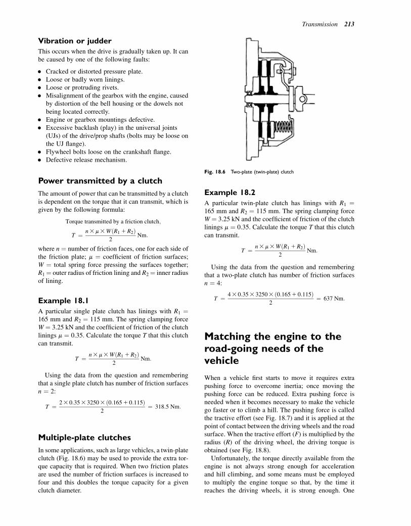
Vibration or judder
This occurs when the drive is gradually taken up. It canbe caused by one of the following faults:
� Cracked or distorted pressure plate.� Loose or badly worn linings.� Loose or protruding rivets.� Misalignment of the gearbox with the engine, caused
by distortion of the bell housing or the dowels notbeing located correctly.
� Engine or gearbox mountings defective.� Excessive backlash (play) in the universal joints
(UJs) of the drive/prop shafts (bolts may be loose onthe UJ flange).
� Flywheel bolts loose on the crankshaft flange.� Defective release mechanism.
Power transmitted by a clutch
The amount of power that can be transmitted by a clutchis dependent on the torque that it can transmit, which isgiven by the following formula:
Torque transmitted by a friction clutch;
T ¼ n3m3WðR1 1R2Þ2
Nm:
where n ¼ number of friction faces, one for each side ofthe friction plate; m ¼ coefficient of friction surfaces;W ¼ total spring force pressing the surfaces together;R1¼ outer radius of friction lining and R2¼ inner radiusof lining.
Example 18.1
A particular single plate clutch has linings with R1 ¼165 mm and R2 ¼ 115 mm. The spring clamping forceW ¼ 3.25 kN and the coefficient of friction of the clutchlinings m ¼ 0.35. Calculate the torque T that this clutchcan transmit.
T ¼ n3m3WðR1 1R2Þ2
Nm:
Using the data from the question and rememberingthat a single plate clutch has number of friction surfacesn ¼ 2:
T ¼ 23 0:353 32503 ð0:1651 0:115Þ2
¼ 318:5 Nm:
Multiple-plate clutches
In some applications, such as large vehicles, a twin-plateclutch (Fig. 18.6) may be used to provide the extra tor-que capacity that is required. When two friction platesare used the number of friction surfaces is increased tofour and this doubles the torque capacity for a givenclutch diameter.
Example 18.2
A particular twin-plate clutch has linings with R1 ¼165 mm and R2 ¼ 115 mm. The spring clamping forceW ¼ 3.25 kN and the coefficient of friction of the clutchlinings m ¼ 0.35. Calculate the torque T that this clutchcan transmit.
T ¼ n3m3WðR1 1R2Þ2
Nm:
Using the data from the question and rememberingthat a two-plate clutch has number of friction surfacesn ¼ 4:
T ¼ 43 0:353 32503 ð0:1651 0:115Þ2
¼ 637 Nm:
Matching the engine to theroad-going needs of thevehicle
When a vehicle first starts to move it requires extrapushing force to overcome inertia; once moving thepushing force can be reduced. Extra pushing force isneeded when it becomes necessary to make the vehiclego faster or to climb a hill. The pushing force is calledthe tractive effort (see Fig. 18.7) and it is applied at thepoint of contact between the driving wheels and the roadsurface. When the tractive effort (F) is multiplied by theradius (R) of the driving wheel, the driving torque isobtained (see Fig. 18.8).
Unfortunately, the torque directly available from theengine is not always strong enough for accelerationand hill climbing, and some means must be employedto multiply the engine torque so that, by the time itreaches the driving wheels, it is strong enough. One
Fig. 18.6 Two-plate (twin-plate) clutch
Transmission 213
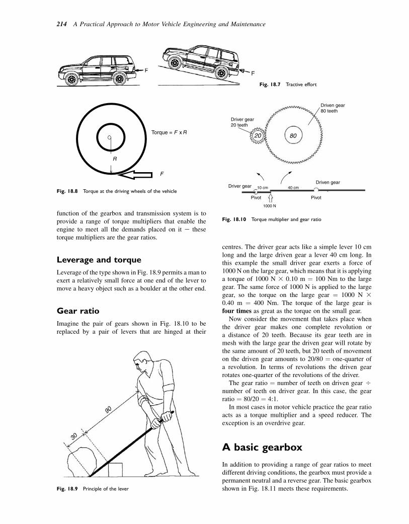
function of the gearbox and transmission system is toprovide a range of torque multipliers that enable theengine to meet all the demands placed on it e thesetorque multipliers are the gear ratios.
Leverage and torque
Leverage of the type shown in Fig. 18.9 permits a man toexert a relatively small force at one end of the lever tomove a heavy object such as a boulder at the other end.
Gear ratio
Imagine the pair of gears shown in Fig. 18.10 to bereplaced by a pair of levers that are hinged at their
centres. The driver gear acts like a simple lever 10 cmlong and the large driven gear a lever 40 cm long. Inthis example the small driver gear exerts a force of1000 N on the large gear, which means that it is applyinga torque of 1000 N 3 0.10 m ¼ 100 Nm to the largegear. The same force of 1000 N is applied to the largegear, so the torque on the large gear ¼ 1000 N 30.40 m ¼ 400 Nm. The torque of the large gear isfour times as great as the torque on the small gear.
Now consider the movement that takes place whenthe driver gear makes one complete revolution ora distance of 20 teeth. Because its gear teeth are inmesh with the large gear the driven gear will rotate bythe same amount of 20 teeth, but 20 teeth of movementon the driven gear amounts to 20/80 ¼ one-quarter ofa revolution. In terms of revolutions the driven gearrotates one-quarter of the revolutions of the driver.
The gear ratio ¼ number of teeth on driven gear Onumber of teeth on driver gear. In this case, the gearratio ¼ 80/20 ¼ 4:1.
In most cases in motor vehicle practice the gear ratioacts as a torque multiplier and a speed reducer. Theexception is an overdrive gear.
A basic gearbox
In addition to providing a range of gear ratios to meetdifferent driving conditions, the gearbox must provide apermanent neutral and a reverse gear. The basic gearboxshown in Fig. 18.11 meets these requirements.
R
F
Torque = F x R
Fig. 18.8 Torque at the driving wheels of the vehicle
Fig. 18.9 Principle of the lever
Driver gear20 teeth
Driven gear80 teeth
Driven gearDriver gear
PivotPivot
40 cm
8020
1000 N
10 cm
Fig. 18.10 Torque multiplier and gear ratio
Fig. 18.7 Tractive effort
214 A Practical Approach to Motor Vehicle Engineering and Maintenance

The sliding mesh gearbox shown in Fig. 18.11 hasthree shafts:
� The primary shaft, which transmits the drive from theengine and clutch to the gearbox e it is also calledthe first motion shaft and it carries the gear that drivesthe lay shaft gears.
� The layshaft e the gears on the layshaft areconnected together and they are all driven at the samespeed, by the first motion shaft gear.
� The mainshaft e this is splined so that the gears canslide along it. When a gear ratio is required therequired gear on the mainshaft is moved along until itis engaged with the corresponding gear on thelayshaft.
The gears are moved along the shaft by means of theselector mechanism, which is operated by the gear lever.
The gearbox shown in Fig. 18.11 has four forwardspeeds. Figure 18.12 shows how the different ratiosare obtained. When the dog clutch is engaged with thefirst motion shaft the drive is direct to the mainshaft ethis provides the fourth gear, which is also called topgear. The next gear ratio is third gear; the mainshaftgear is moved along the shaft until it engages with thethird gear on the layshaft e at the same time, the dogclutch disengages from top gear so that only one gearis engaged. When third gear is disengaged and returnedto its neutral position, second gear can be engaged.When first gear is required, second gear is moved outof mesh as the first gear is moved into mesh with the cor-responding gear on the layshafte first gear is also calledbottom gear.
Considerable skill is required to drive a vehicle equip-ped with a sliding mesh gearbox because it is difficult to
slide the gears into mesh without causing them to crashinto each other e that is why they are sometimesreferred to as crash gearboxes.
The constant mesh andsynchromesh gearbox
The constant mesh gearbox (Fig. 18.13) overcomes thedifficulty of engaging sliding gears by using a dogclutch of the type shown in Fig. 18.14 to connect thegears to the mainshaft as they are required. The basicconstant mesh gearbox is similar in layout to the slidingmesh one, the main difference being that the gears onthe mainshaft are free to rotate on it. In between themainshaft gears are the dog clutches that are splinedto it e when a particular gear ratio is required, theappropriate dog clutch is moved along the mainshaftto connect the gear to it.
Synchromesh
Synchromesh mechanisms of the type shown inFig. 18.15 perform the same function as the dog clutchin the constant mesh gearbox. The main difference liesin the small cone clutch that is designed to match thespeed of the mainshaft to that of the mainshaft gearthat is being selected e when the speeds are the same(synchronized) the gear can be connected to the shaftwithout any grating sounds.
The synchromesh hub is splined to the mainshaft andit moves axially along it when moved by the gearselector mechanism. The springs and balls that areplaced around the circumference of the hub provide
Primary shaftInput from engine
Three selectorshafts and forks
Dogs
Top SecondFirstThird
Gear lever end
Reverse
Reverseidler gear
Layshaft
MainshaftOutput to final drive
Fig. 18.11 A basic sliding mesh gearbox
Transmission 215

the load that controls the movement of the sleeve acrossthe hub. The inner edge of the selector ring contains thedog teeth that engage with the corresponding ones onthe gear that is being selected. Initial movement of thesynchromesh unit brings the synchronizing cones intocontact and this action synchronizes the speeds of thetwo sets of dog teeth that are being engaged. Furthermovement of the selector mechanism causes the sleeveto override the spring and ball to achieve the fullyengaged position e the unit remains in this position
until another gear is selected. When this type ofsynchromesh is used carefully it provides a reliablemethod of achieving smooth gear changing; however,if hurried gear changes are attempted a certain amountof clashing of the dog teeth may result. The baulk ringtype of synchromesh is a device that is designed to over-come this difficulty and thus provide for faster gearchanges, where they are required.
The baulk-ring synchromesh
The principal differences between the baulk-ring type ofsynchromesh (Fig. 18.16) and the constant-load one arethe baulking rings and the shifting plates. The baulkrings and spring-loaded shifting plates are designed toprevent the dog teeth from engaging until the twomembers that are being connected are rotating at thesame speed. Unlike the constant-load synchromesh,the synchronizing cones (baulk rings) are separatefrom the hub and they can rotate a few degrees relativeto it. It is this feature that should ensure synchronizationat whatever speed of gear change is required.
Reverse gear
In addition to providing a range of gears for forwardmotion of the vehicle it is necessary for the gearbox toprovide a means of reversing, and this is achieved bymeans of an additional gear called an idler that is inter-posed between the mainshaft gear and the layshaft, asshown in Fig. 18.17.
Direct drive – dog clutch engaged
4th gear – Top gear
3rd gear
First gear – bottom gear2nd gear
Fig. 18.12 The four gear ratios of the sliding mesh gearbox
Dog clutches moved along themainshaft to lock the gear to themainshaft
Mainshaft gears permanentlymeshed with layshaft gears
Fig. 18.13 The constant mesh principle
216 A Practical Approach to Motor Vehicle Engineering and Maintenance
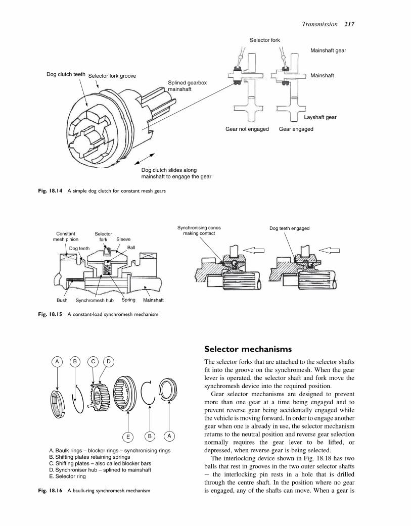
Selector mechanisms
The selector forks that are attached to the selector shaftsfit into the groove on the synchromesh. When the gearlever is operated, the selector shaft and fork move thesynchromesh device into the required position.
Gear selector mechanisms are designed to preventmore than one gear at a time being engaged and toprevent reverse gear being accidentally engaged whilethe vehicle is moving forward. In order to engage anothergear when one is already in use, the selector mechanismreturns to the neutral position and reverse gear selectionnormally requires the gear lever to be lifted, ordepressed, when reverse gear is being selected.
The interlocking device shown in Fig. 18.18 has twoballs that rest in grooves in the two outer selector shaftse the interlocking pin rests in a hole that is drilledthrough the centre shaft. In the position where no gearis engaged, any of the shafts can move. When a gear is
Dog clutch teeth Selector fork grooveSplined gearboxmainshaft
Dog clutch slides alongmainshaft to engage the gear
Gear engagedGear not engaged
Layshaft gear
Mainshaft
Mainshaft gear
Selector fork
Fig. 18.14 A simple dog clutch for constant mesh gears
Constantmesh pinion
Selectorfork
Dog teeth Ball
Sleeve
SpringBush Mainshaft
Synchronising conesmaking contact
Dog teeth engaged
Synchromesh hub
Fig. 18.15 A constant-load synchromesh mechanism
A B C D
E B A
A. Baulk rings – blocker rings – synchronising ringsB. Shifting plates retaining springsC. Shifting plates – also called blocker barsD. Synchroniser hub – splined to mainshaftE. Selector ring
Fig. 18.16 A baulk-ring synchromesh mechanism
Transmission 217
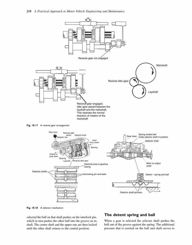
selected the ball on that shaft pushes on the interlock pin,which in turn pushes the other ball into the groove on itsshaft. The centre shaft and the upper one are then lockeduntil the other shaft returns to the central position.
The detent spring and ball
When a gear is selected the selector shaft pushes theball out of the groove against the spring. The additionalpressure that is exerted on the ball and shaft serves to
Reverse gear not engaged
Reverse idler gear
Reverse gear engaged.Idler gear placed between thelayshaft and the mainshaft.This reverses the normaldirection of rotation of themainshaft
Layshaft
Mainshaft
Fig. 18.17 A reverse gear arrangement
Gear lever Reverse lightswitch
Inputfrom clutch
Gear lever
Main or outputshaft
Spring loaded ballholds selector shaft in position
Selector shaft
Selector shaft grooves
Selector forks Selector rod
Detent – spring and ball
Bearing
Output to prop other
BearingLayshaft
Selector shafts
Reverse idler gear
Interlocking pin and balls
Hatched area is gearboxcasing
Fig. 18.18 A selector mechanism
218 A Practical Approach to Motor Vehicle Engineering and Maintenance
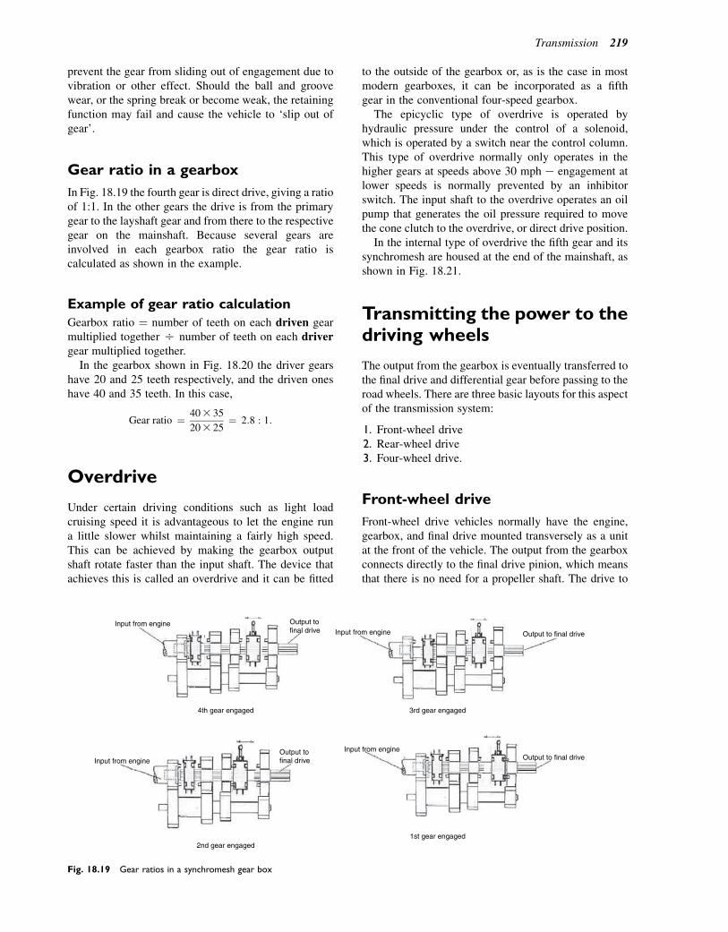
prevent the gear from sliding out of engagement due tovibration or other effect. Should the ball and groovewear, or the spring break or become weak, the retainingfunction may fail and cause the vehicle to ‘slip out ofgear’.
Gear ratio in a gearbox
In Fig. 18.19 the fourth gear is direct drive, giving a ratioof 1:1. In the other gears the drive is from the primarygear to the layshaft gear and from there to the respectivegear on the mainshaft. Because several gears areinvolved in each gearbox ratio the gear ratio iscalculated as shown in the example.
Example of gear ratio calculation
Gearbox ratio ¼ number of teeth on each driven gearmultiplied together O number of teeth on each drivergear multiplied together.
In the gearbox shown in Fig. 18.20 the driver gearshave 20 and 25 teeth respectively, and the driven oneshave 40 and 35 teeth. In this case,
Gear ratio ¼ 403 35
203 25¼ 2:8 : 1:
Overdrive
Under certain driving conditions such as light loadcruising speed it is advantageous to let the engine runa little slower whilst maintaining a fairly high speed.This can be achieved by making the gearbox outputshaft rotate faster than the input shaft. The device thatachieves this is called an overdrive and it can be fitted
to the outside of the gearbox or, as is the case in mostmodern gearboxes, it can be incorporated as a fifthgear in the conventional four-speed gearbox.
The epicyclic type of overdrive is operated byhydraulic pressure under the control of a solenoid,which is operated by a switch near the control column.This type of overdrive normally only operates in thehigher gears at speeds above 30 mph e engagement atlower speeds is normally prevented by an inhibitorswitch. The input shaft to the overdrive operates an oilpump that generates the oil pressure required to movethe cone clutch to the overdrive, or direct drive position.
In the internal type of overdrive the fifth gear and itssynchromesh are housed at the end of the mainshaft, asshown in Fig. 18.21.
Transmitting the power to thedriving wheels
The output from the gearbox is eventually transferred tothe final drive and differential gear before passing to theroad wheels. There are three basic layouts for this aspectof the transmission system:
1. Front-wheel drive2. Rear-wheel drive3. Four-wheel drive.
Front-wheel drive
Front-wheel drive vehicles normally have the engine,gearbox, and final drive mounted transversely as a unitat the front of the vehicle. The output from the gearboxconnects directly to the final drive pinion, which meansthat there is no need for a propeller shaft. The drive to
Input from engine
4th gear engaged 3rd gear engaged
1st gear engaged
Output to final drive
Output to final drive
Output to final drive
Output to final drive
Input from engine
Input from engine
2nd gear engaged
Input from engine
Fig. 18.19 Gear ratios in a synchromesh gear box
Transmission 219

the wheels is carried by the drive shafts, which incorpo-rate constant-velocity joints that allow the wheels to besteered while they are being driven. A typical exampleof a front-wheel drive arrangement is shown in Fig. 18.22.
Rear-wheel drive
The power from the gearbox is transferred to the rearaxle by means of the propeller shaft using a layoutsimilar to the Hotchkiss drive shown in Fig. 18.23. Inthe example shown, the axle is attached to the leafsprings, which hold the axle in place and provide the
springing necessary for suspension. When in motionthe axle is subject to movements that necessitate theuse of a sliding joint and two universal joints. Thesliding joint is required to allow for a slight increasein the distance between the gearbox and the axle thatoccurs as the axle rises and falls when the vehicle movesacross bumps in the road surface. The second universaljoint at the axle end of the propeller shaft allows for thepartial rotation of the axle casing that occurs underacceleration and braking. This motion causes thesprings to flex and this also affects the distance betweenthe gearbox and the axle. In addition, the second
1000 rev / min
1N20
40 25
35
Fig. 18.20 Second gear ratio
Cone clutch locks sunwheel and annulus togive direct drive
Cone clutch locks sun wheel tothe casing to give overdrive
Output to propellershaft Output to
propeller shaft
Output shaft
Epicyclic gear – external type overdrive
Overdrive5th Gear
Final drive
Input from engine1000 rev/min
Output to final drive1100 rev/min
Internal type overdrive – 5th gear
Input fromgearbox
Input from gearbox
Hydraulic pressure
Planet wheel
Sun wheelAnnulus
Cone clutch
Fig. 18.21 Two types of overdrive
220 A Practical Approach to Motor Vehicle Engineering and Maintenance
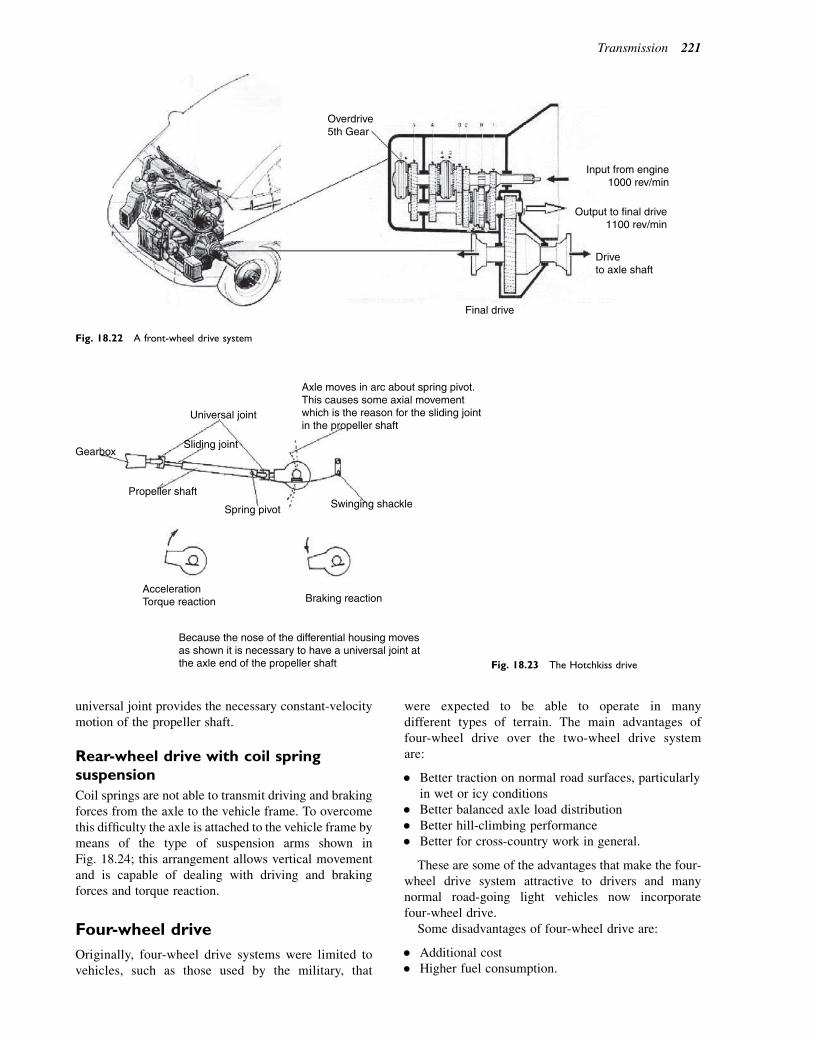
universal joint provides the necessary constant-velocitymotion of the propeller shaft.
Rear-wheel drive with coil springsuspension
Coil springs are not able to transmit driving and brakingforces from the axle to the vehicle frame. To overcomethis difficulty the axle is attached to the vehicle frame bymeans of the type of suspension arms shown inFig. 18.24; this arrangement allows vertical movementand is capable of dealing with driving and brakingforces and torque reaction.
Four-wheel drive
Originally, four-wheel drive systems were limited tovehicles, such as those used by the military, that
were expected to be able to operate in manydifferent types of terrain. The main advantages offour-wheel drive over the two-wheel drive systemare:
� Better traction on normal road surfaces, particularlyin wet or icy conditions
� Better balanced axle load distribution� Better hill-climbing performance� Better for cross-country work in general.
These are some of the advantages that make the four-wheel drive system attractive to drivers and manynormal road-going light vehicles now incorporatefour-wheel drive.
Some disadvantages of four-wheel drive are:
� Additional cost� Higher fuel consumption.
Overdrive5th Gear
Input from engine1000 rev/min
Output to final drive1100 rev/min
Driveto axle shaft
Final drive
Fig. 18.22 A front-wheel drive system
Gearbox
Universal joint
Sliding joint
Propeller shaft
Spring pivot
AccelerationTorque reaction Braking reaction
Swinging shackle
Axle moves in arc about spring pivot.This causes some axial movementwhich is the reason for the sliding jointin the propeller shaft
Because the nose of the differential housing movesas shown it is necessary to have a universal joint atthe axle end of the propeller shaft Fig. 18.23 The Hotchkiss drive
Transmission 221
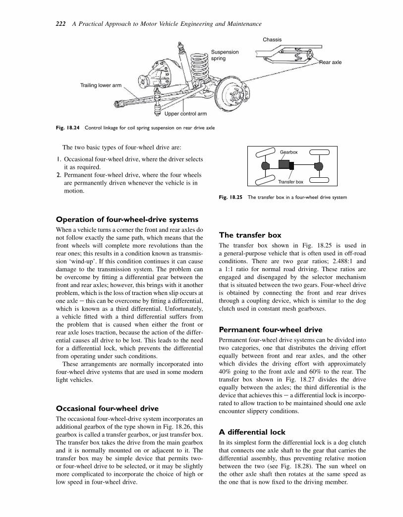
The two basic types of four-wheel drive are:
1. Occasional four-wheel drive, where the driver selectsit as required.
2. Permanent four-wheel drive, where the four wheelsare permanently driven whenever the vehicle is inmotion.
Operation of four-wheel-drive systems
When a vehicle turns a corner the front and rear axles donot follow exactly the same path, which means that thefront wheels will complete more revolutions than therear ones; this results in a condition known as transmis-sion ‘wind-up’. If this condition continues it can causedamage to the transmission system. The problem canbe overcome by fitting a differential gear between thefront and rear axles; however, this brings with it anotherproblem, which is the loss of traction when slip occurs atone axle e this can be overcome by fitting a differential,which is known as a third differential. Unfortunately,a vehicle fitted with a third differential suffers fromthe problem that is caused when either the front orrear axle loses traction, because the action of the differ-ential causes all drive to be lost. This leads to the needfor a differential lock, which prevents the differentialfrom operating under such conditions.
These arrangements are normally incorporated intofour-wheel drive systems that are used in some modernlight vehicles.
Occasional four-wheel drive
The occasional four-wheel-drive system incorporates anadditional gearbox of the type shown in Fig. 18.26, thisgearbox is called a transfer gearbox, or just transfer box.The transfer box takes the drive from the main gearboxand it is normally mounted on or adjacent to it. Thetransfer box may be simple device that permits two-or four-wheel drive to be selected, or it may be slightlymore complicated to incorporate the choice of high orlow speed in four-wheel drive.
The transfer box
The transfer box shown in Fig. 18.25 is used ina general-purpose vehicle that is often used in off-roadconditions. There are two gear ratios; 2.488:1 anda 1:1 ratio for normal road driving. These ratios areengaged and disengaged by the selector mechanismthat is situated between the two gears. Four-wheel driveis obtained by connecting the front and rear drivesthrough a coupling device, which is similar to the dogclutch used in constant mesh gearboxes.
Permanent four-wheel drive
Permanent four-wheel drive systems can be divided intotwo categories, one that distributes the driving effortequally between front and rear axles, and the otherwhich divides the driving effort with approximately40% going to the front axle and 60% to the rear. Thetransfer box shown in Fig. 18.27 divides the driveequally between the axles; the third differential is thedevice that achieves thise a differential lock is incorpo-rated to allow traction to be maintained should one axleencounter slippery conditions.
A differential lock
In its simplest form the differential lock is a dog clutchthat connects one axle shaft to the gear that carries thedifferential assembly, thus preventing relative motionbetween the two (see Fig. 18.28). The sun wheel onthe other axle shaft then rotates at the same speed asthe one that is now fixed to the driving member.
Suspensionspring
Chassis
Rear axle
Trailing lower arm
Upper control arm
Fig. 18.24 Control linkage for coil spring suspension on rear drive axle
Gearbox
Transfer box
Fig. 18.25 The transfer box in a four-wheel drive system
222 A Practical Approach to Motor Vehicle Engineering and Maintenance

Permanent four-wheel drive viaa viscous coupling
As the demand for four-wheel drive vehicles for privatemotorists increased, several different systems weredeveloped that made use of two devices, one to appor-tion the drive between the axles, the other to overcomethe problem of the axles running at different speeds. Anepicyclic type of differential may be used to apportionthe torque between the axles and a viscous coupling(see Fig. 18.29) may be used to deal with differencesin axle speeds.
Input shaft from gearbox
Drive to front axleDrive to rear axle
Third differential
Selector for high or low ratio
Fig. 18.27 A permanent four-wheel drive trans-
fer box with third differential
Input shaft from gearbox
Drive to rear axleDrive to front axle
Selector for two- or four-wheel drive
Selector for low or high ratioFig. 18.26 A transfer gearbox for occasional four-
wheel drive
Part of diff cage Selector groove
Output shaft
Diff lock dog clutchSplined to output shaft
Dog clutch teethengage to lockoutput shaft to diff cage
Sun wheel
Fig. 18.28 Principle of a differential lock
Transmission 223
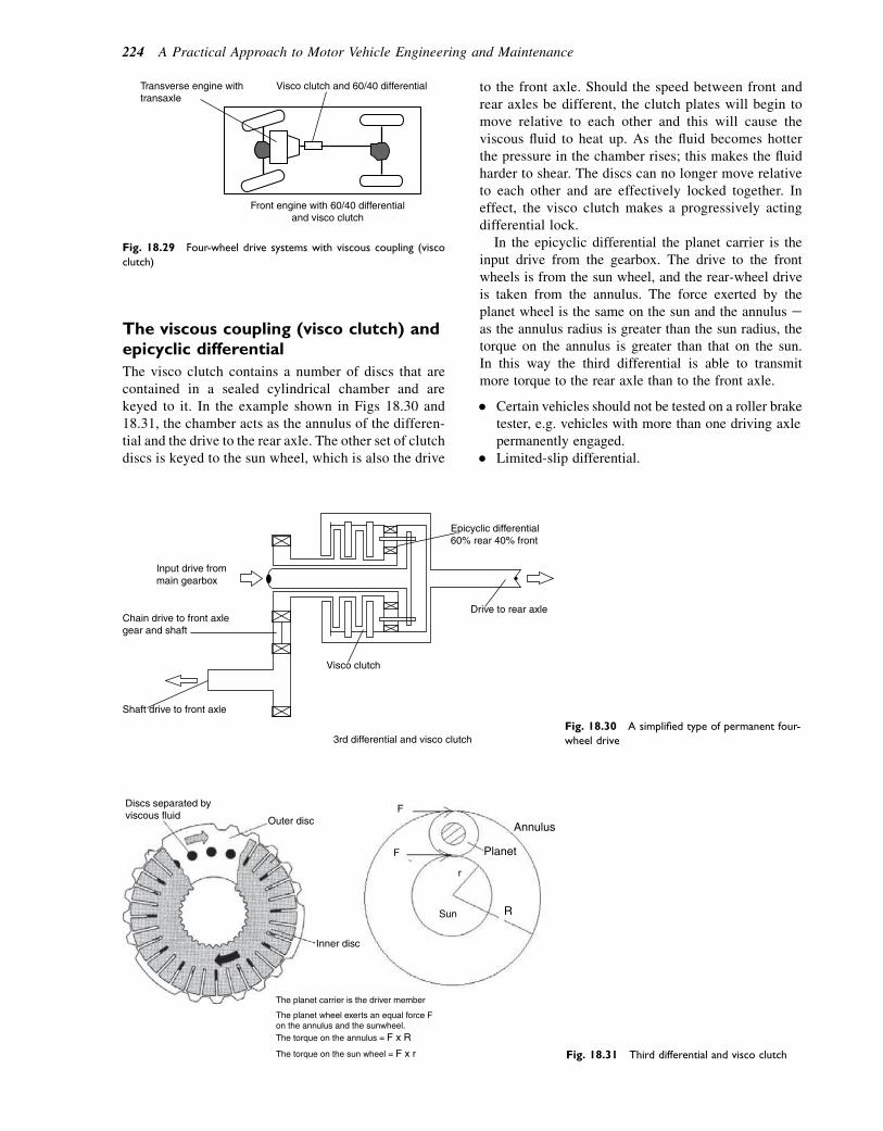
The viscous coupling (visco clutch) andepicyclic differential
The visco clutch contains a number of discs that arecontained in a sealed cylindrical chamber and arekeyed to it. In the example shown in Figs 18.30 and18.31, the chamber acts as the annulus of the differen-tial and the drive to the rear axle. The other set of clutchdiscs is keyed to the sun wheel, which is also the drive
to the front axle. Should the speed between front andrear axles be different, the clutch plates will begin tomove relative to each other and this will cause theviscous fluid to heat up. As the fluid becomes hotterthe pressure in the chamber rises; this makes the fluidharder to shear. The discs can no longer move relativeto each other and are effectively locked together. Ineffect, the visco clutch makes a progressively actingdifferential lock.
In the epicyclic differential the planet carrier is theinput drive from the gearbox. The drive to the frontwheels is from the sun wheel, and the rear-wheel driveis taken from the annulus. The force exerted by theplanet wheel is the same on the sun and the annulus eas the annulus radius is greater than the sun radius, thetorque on the annulus is greater than that on the sun.In this way the third differential is able to transmitmore torque to the rear axle than to the front axle.
� Certain vehicles should not be tested on a roller braketester, e.g. vehicles with more than one driving axlepermanently engaged.
� Limited-slip differential.
Visco clutch and 60/40 differential
Front engine with 60/40 differentialand visco clutch
Transverse engine withtransaxle
Fig. 18.29 Four-wheel drive systems with viscous coupling (visco
clutch)
Input drive frommain gearbox
Chain drive to front axlegear and shaft
Shaft drive to front axle
Visco clutch
Drive to rear axle
Epicyclic differential60% rear 40% front
3rd differential and visco clutchFig. 18.30 A simplified type of permanent four-
wheel drive
Discs separated byviscous fluid Outer disc
Inner disc
The planet carrier is the driver member
The torque on the annulus = F x R
The torque on the sun wheel = F x r
The planet wheel exerts an equal force Fon the annulus and the sunwheel.
F
F
R
Planet
Annulus
Sun
r
Fig. 18.31 Third differential and visco clutch
224 A Practical Approach to Motor Vehicle Engineering and Maintenance
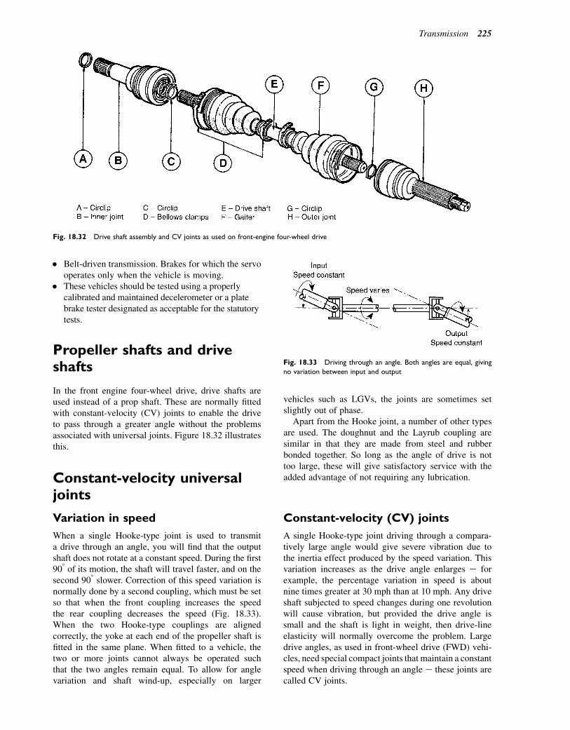
� Belt-driven transmission. Brakes for which the servooperates only when the vehicle is moving.
� These vehicles should be tested using a properlycalibrated and maintained decelerometer or a platebrake tester designated as acceptable for the statutorytests.
Propeller shafts and driveshafts
In the front engine four-wheel drive, drive shafts areused instead of a prop shaft. These are normally fittedwith constant-velocity (CV) joints to enable the driveto pass through a greater angle without the problemsassociated with universal joints. Figure 18.32 illustratesthis.
Constant-velocity universaljoints
Variation in speed
When a single Hooke-type joint is used to transmita drive through an angle, you will find that the outputshaft does not rotate at a constant speed. During the first908 of its motion, the shaft will travel faster, and on thesecond 908 slower. Correction of this speed variation isnormally done by a second coupling, which must be setso that when the front coupling increases the speedthe rear coupling decreases the speed (Fig. 18.33).When the two Hooke-type couplings are alignedcorrectly, the yoke at each end of the propeller shaft isfitted in the same plane. When fitted to a vehicle, thetwo or more joints cannot always be operated suchthat the two angles remain equal. To allow for anglevariation and shaft wind-up, especially on larger
vehicles such as LGVs, the joints are sometimes setslightly out of phase.
Apart from the Hooke joint, a number of other typesare used. The doughnut and the Layrub coupling aresimilar in that they are made from steel and rubberbonded together. So long as the angle of drive is nottoo large, these will give satisfactory service with theadded advantage of not requiring any lubrication.
Constant-velocity (CV) joints
A single Hooke-type joint driving through a compara-tively large angle would give severe vibration due tothe inertia effect produced by the speed variation. Thisvariation increases as the drive angle enlarges e forexample, the percentage variation in speed is aboutnine times greater at 30 mph than at 10 mph. Any driveshaft subjected to speed changes during one revolutionwill cause vibration, but provided the drive angle issmall and the shaft is light in weight, then drive-lineelasticity will normally overcome the problem. Largedrive angles, as used in front-wheel drive (FWD) vehi-cles, need special compact joints that maintain a constantspeed when driving through an angle e these joints arecalled CV joints.
Fig. 18.32 Drive shaft assembly and CV joints as used on front-engine four-wheel drive
Fig. 18.33 Driving through an angle. Both angles are equal, giving
no variation between input and output
Transmission 225
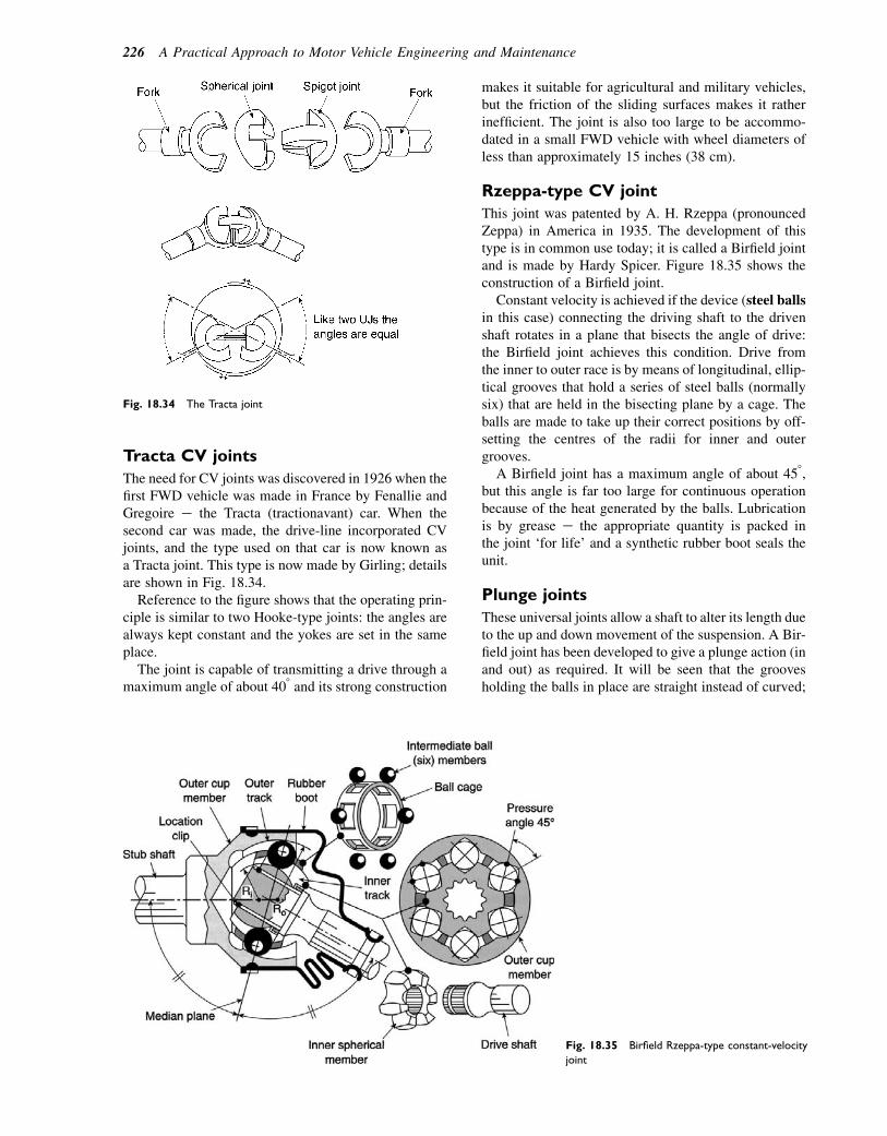
Tracta CV joints
The need for CV joints was discovered in 1926 when thefirst FWD vehicle was made in France by Fenallie andGregoire e the Tracta (tractionavant) car. When thesecond car was made, the drive-line incorporated CVjoints, and the type used on that car is now known asa Tracta joint. This type is now made by Girling; detailsare shown in Fig. 18.34.
Reference to the figure shows that the operating prin-ciple is similar to two Hooke-type joints: the angles arealways kept constant and the yokes are set in the sameplace.
The joint is capable of transmitting a drive through amaximum angle of about 408 and its strong construction
makes it suitable for agricultural and military vehicles,but the friction of the sliding surfaces makes it ratherinefficient. The joint is also too large to be accommo-dated in a small FWD vehicle with wheel diameters ofless than approximately 15 inches (38 cm).
Rzeppa-type CV joint
This joint was patented by A. H. Rzeppa (pronouncedZeppa) in America in 1935. The development of thistype is in common use today; it is called a Birfield jointand is made by Hardy Spicer. Figure 18.35 shows theconstruction of a Birfield joint.
Constant velocity is achieved if the device (steel ballsin this case) connecting the driving shaft to the drivenshaft rotates in a plane that bisects the angle of drive:the Birfield joint achieves this condition. Drive fromthe inner to outer race is by means of longitudinal, ellip-tical grooves that hold a series of steel balls (normallysix) that are held in the bisecting plane by a cage. Theballs are made to take up their correct positions by off-setting the centres of the radii for inner and outergrooves.
A Birfield joint has a maximum angle of about 458,but this angle is far too large for continuous operationbecause of the heat generated by the balls. Lubricationis by grease e the appropriate quantity is packed inthe joint ‘for life’ and a synthetic rubber boot seals theunit.
Plunge joints
These universal joints allow a shaft to alter its length dueto the up and down movement of the suspension. A Bir-field joint has been developed to give a plunge action (inand out) as required. It will be seen that the groovesholding the balls in place are straight instead of curved;
Fig. 18.34 The Tracta joint
Fig. 18.35 Birfield Rzeppa-type constant-velocity
joint
226 A Practical Approach to Motor Vehicle Engineering and Maintenance
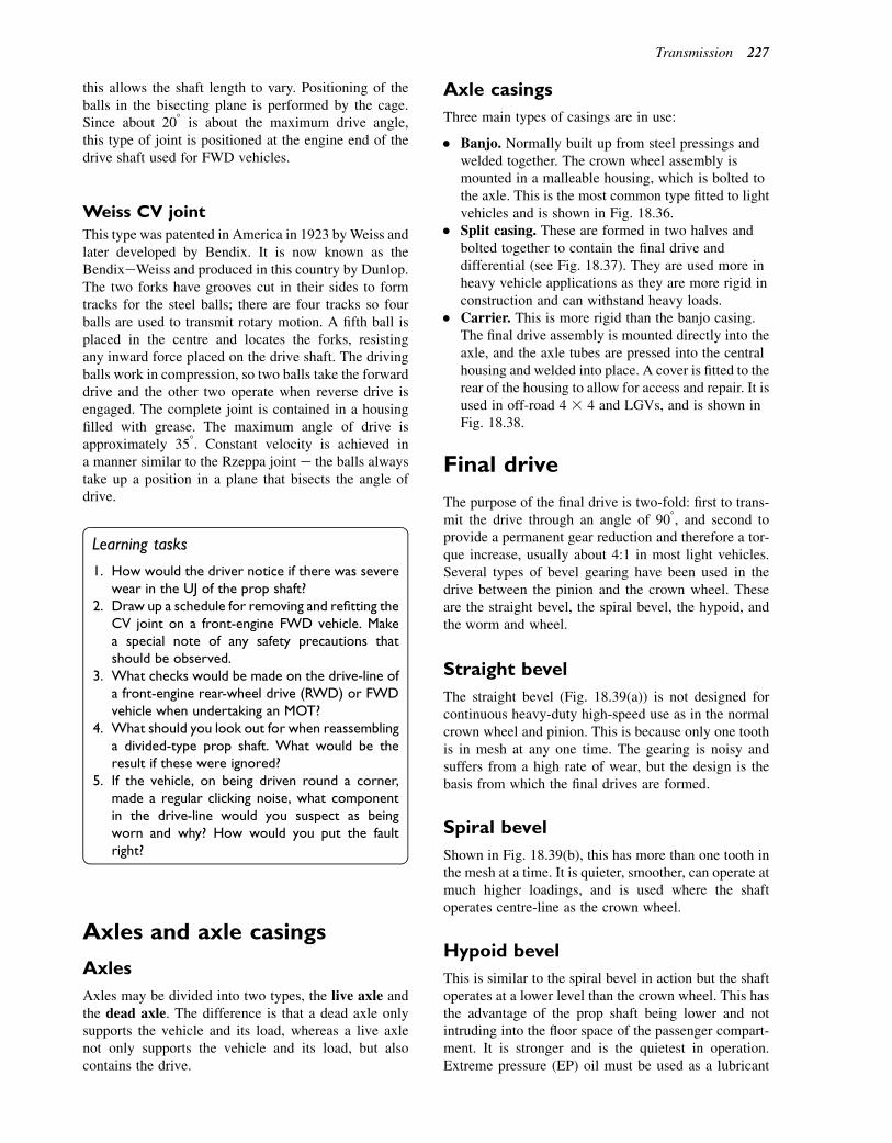
this allows the shaft length to vary. Positioning of theballs in the bisecting plane is performed by the cage.Since about 208 is about the maximum drive angle,this type of joint is positioned at the engine end of thedrive shaft used for FWD vehicles.
Weiss CV joint
This type was patented in America in 1923 byWeiss andlater developed by Bendix. It is now known as theBendixeWeiss and produced in this country by Dunlop.The two forks have grooves cut in their sides to formtracks for the steel balls; there are four tracks so fourballs are used to transmit rotary motion. A fifth ball isplaced in the centre and locates the forks, resistingany inward force placed on the drive shaft. The drivingballs work in compression, so two balls take the forwarddrive and the other two operate when reverse drive isengaged. The complete joint is contained in a housingfilled with grease. The maximum angle of drive isapproximately 358. Constant velocity is achieved ina manner similar to the Rzeppa joint e the balls alwaystake up a position in a plane that bisects the angle ofdrive.
Learning tasks
1. How would the driver notice if there was severewear in the UJ of the prop shaft?
2. Draw up a schedule for removing and refitting theCV joint on a front-engine FWD vehicle. Makea special note of any safety precautions thatshould be observed.
3. What checks would be made on the drive-line ofa front-engine rear-wheel drive (RWD) or FWDvehicle when undertaking an MOT?
4. What should you look out for when reassemblinga divided-type prop shaft. What would be theresult if these were ignored?
5. If the vehicle, on being driven round a corner,made a regular clicking noise, what componentin the drive-line would you suspect as beingworn and why? How would you put the faultright?
Axles and axle casings
Axles
Axles may be divided into two types, the live axle andthe dead axle. The difference is that a dead axle onlysupports the vehicle and its load, whereas a live axlenot only supports the vehicle and its load, but alsocontains the drive.
Axle casings
Three main types of casings are in use:
� Banjo. Normally built up from steel pressings andwelded together. The crown wheel assembly ismounted in a malleable housing, which is bolted tothe axle. This is the most common type fitted to lightvehicles and is shown in Fig. 18.36.
� Split casing. These are formed in two halves andbolted together to contain the final drive anddifferential (see Fig. 18.37). They are used more inheavy vehicle applications as they are more rigid inconstruction and can withstand heavy loads.
� Carrier. This is more rigid than the banjo casing.The final drive assembly is mounted directly into theaxle, and the axle tubes are pressed into the centralhousing and welded into place. A cover is fitted to therear of the housing to allow for access and repair. It isused in off-road 4 3 4 and LGVs, and is shown inFig. 18.38.
Final drive
The purpose of the final drive is two-fold: first to trans-mit the drive through an angle of 908, and second toprovide a permanent gear reduction and therefore a tor-que increase, usually about 4:1 in most light vehicles.Several types of bevel gearing have been used in thedrive between the pinion and the crown wheel. Theseare the straight bevel, the spiral bevel, the hypoid, andthe worm and wheel.
Straight bevel
The straight bevel (Fig. 18.39(a)) is not designed forcontinuous heavy-duty high-speed use as in the normalcrown wheel and pinion. This is because only one toothis in mesh at any one time. The gearing is noisy andsuffers from a high rate of wear, but the design is thebasis from which the final drives are formed.
Spiral bevel
Shown in Fig. 18.39(b), this has more than one tooth inthe mesh at a time. It is quieter, smoother, can operate atmuch higher loadings, and is used where the shaftoperates centre-line as the crown wheel.
Hypoid bevel
This is similar to the spiral bevel in action but the shaftoperates at a lower level than the crown wheel. This hasthe advantage of the prop shaft being lower and notintruding into the floor space of the passenger compart-ment. It is stronger and is the quietest in operation.Extreme pressure (EP) oil must be used as a lubricant
Transmission 227
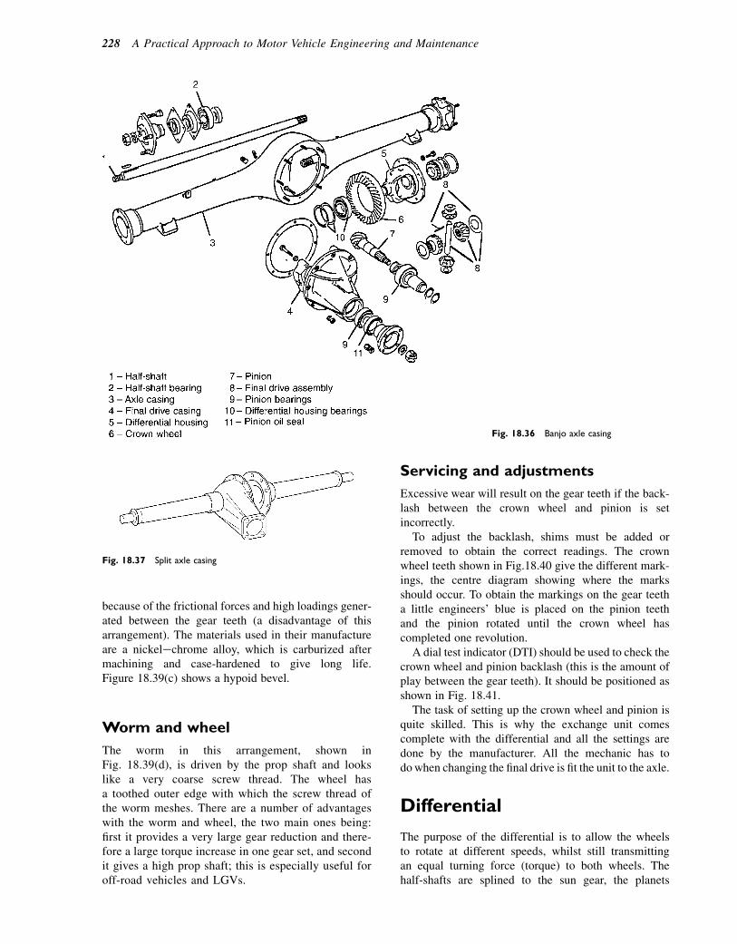
because of the frictional forces and high loadings gener-ated between the gear teeth (a disadvantage of thisarrangement). The materials used in their manufactureare a nickelechrome alloy, which is carburized aftermachining and case-hardened to give long life.Figure 18.39(c) shows a hypoid bevel.
Worm and wheel
The worm in this arrangement, shown inFig. 18.39(d), is driven by the prop shaft and lookslike a very coarse screw thread. The wheel hasa toothed outer edge with which the screw thread ofthe worm meshes. There are a number of advantageswith the worm and wheel, the two main ones being:first it provides a very large gear reduction and there-fore a large torque increase in one gear set, and secondit gives a high prop shaft; this is especially useful foroff-road vehicles and LGVs.
Servicing and adjustments
Excessive wear will result on the gear teeth if the back-lash between the crown wheel and pinion is setincorrectly.
To adjust the backlash, shims must be added orremoved to obtain the correct readings. The crownwheel teeth shown in Fig.18.40 give the different mark-ings, the centre diagram showing where the marksshould occur. To obtain the markings on the gear teetha little engineers’ blue is placed on the pinion teethand the pinion rotated until the crown wheel hascompleted one revolution.
A dial test indicator (DTI) should be used to check thecrown wheel and pinion backlash (this is the amount ofplay between the gear teeth). It should be positioned asshown in Fig. 18.41.
The task of setting up the crown wheel and pinion isquite skilled. This is why the exchange unit comescomplete with the differential and all the settings aredone by the manufacturer. All the mechanic has todowhen changing the final drive is fit the unit to the axle.
Differential
The purpose of the differential is to allow the wheelsto rotate at different speeds, whilst still transmittingan equal turning force (torque) to both wheels. Thehalf-shafts are splined to the sun gear, the planets
Fig. 18.37 Split axle casing
Fig. 18.36 Banjo axle casing
228 A Practical Approach to Motor Vehicle Engineering and Maintenance

transmitting the motion from one sun gear to the otherwhen the vehicle is turning a corner. This is shown inFig. 18.42.
When both drive shafts are travelling at the samespeed, the planet gears orbit (rotate) with the sun gearsbut do not rotate on their shafts. The whole unit acts asa solid drive (see Fig. 18.43).
If one shaft is stopped, the planet gears turn on theirshafts, orbiting round the stationary sun gear and drivingthe other sun gear but twice as fast.
In the final drive the differential is in a housing(sometimes called a cage) to which the crown wheelis bolted. When the car is travelling in a straightline the planet gears orbit, but do not rotate on theirshafts, and the unit drives both half-shafts at thesame speed as the crown wheel and with the sameturning force.
When turning a corner, the sun gear on the inner half-shaft turns more slowly than the crown wheel; the outerhalf-shaft, driven by the other sun gear, turns corre-spondingly faster. The crown wheel turns at the averageof the half-shaft speeds.
A sectioned view of the complete final drive anddifferential arrangement is shown in Fig. 18.44. Boththe crown wheel and pinion are held in the housing bytaper roller bearings. The cross pin acts as the drivefor and the shaft on which the planet gears rotate.
Rear hub bearing and axleshaft arrangements
Three layouts are now commonly used and are subjectedto various forces acting on the axle shaft e for example,twisting when accelerating or braking, bending due tocornering and some of the load, and shear due to thevertical load imposed on the axle shaft.
Semi-floating axle
This hub arrangement, shown in Fig. 18.45(a), is usedon many small light vehicles. The road wheel is attachedto the half-shaft rather than the hub and the bearing isfitted between the half-shaft and the axle casing. There-fore, if a break should occur in the half-shaft inside theaxle casing, the wheel will tilt and very often becomedetached due to the lack of support at the inner end ofthe half-shaft. As can be seen, the shearing point is posi-tioned between the shaft and the axle casing, and theshaft is subject to shearing, bending, and twisting forces.
Three-quarter floating axle
Used on cars and light vans, the main difference is theposition of the bearing, now shown on the outside of
Fig. 18.38 Carrier axle casing
Transmission 229
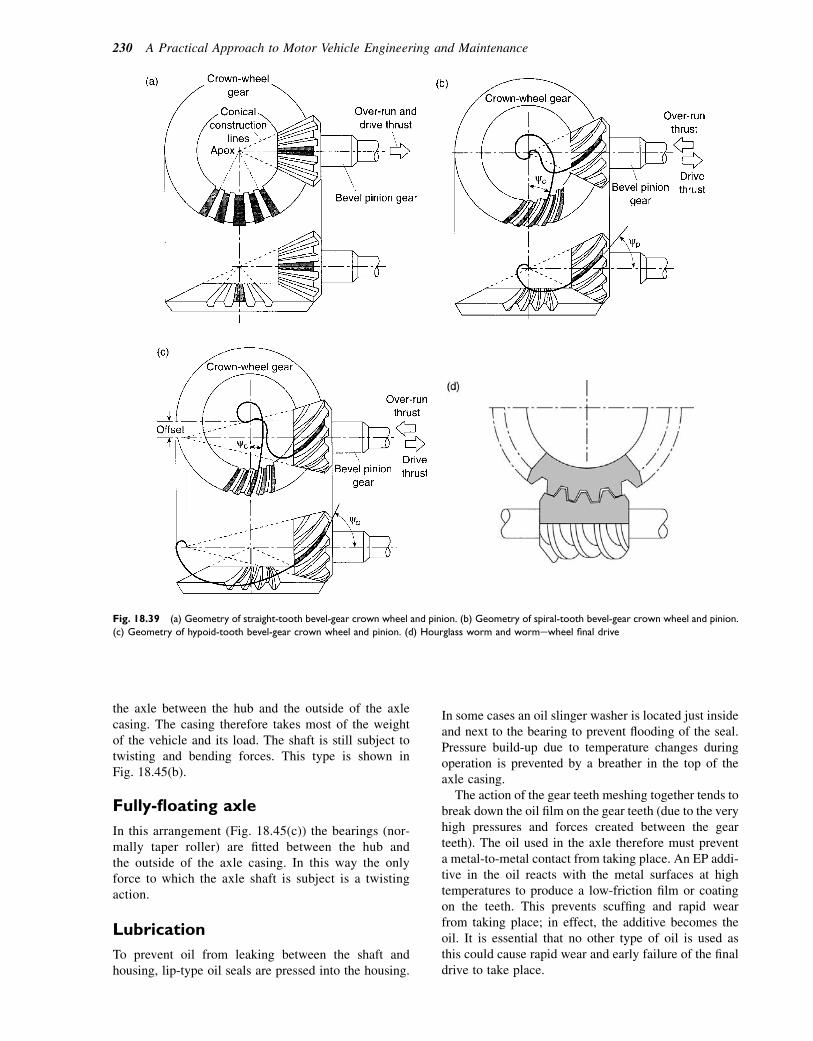
the axle between the hub and the outside of the axlecasing. The casing therefore takes most of the weightof the vehicle and its load. The shaft is still subject totwisting and bending forces. This type is shown inFig. 18.45(b).
Fully-floating axle
In this arrangement (Fig. 18.45(c)) the bearings (nor-mally taper roller) are fitted between the hub andthe outside of the axle casing. In this way the onlyforce to which the axle shaft is subject is a twistingaction.
Lubrication
To prevent oil from leaking between the shaft andhousing, lip-type oil seals are pressed into the housing.
In some cases an oil slinger washer is located just insideand next to the bearing to prevent flooding of the seal.Pressure build-up due to temperature changes duringoperation is prevented by a breather in the top of theaxle casing.
The action of the gear teeth meshing together tends tobreak down the oil film on the gear teeth (due to the veryhigh pressures and forces created between the gearteeth). The oil used in the axle therefore must preventa metal-to-metal contact from taking place. An EP addi-tive in the oil reacts with the metal surfaces at hightemperatures to produce a low-friction film or coatingon the teeth. This prevents scuffing and rapid wearfrom taking place; in effect, the additive becomes theoil. It is essential that no other type of oil is used asthis could cause rapid wear and early failure of the finaldrive to take place.
Fig. 18.39 (a) Geometry of straight-tooth bevel-gear crown wheel and pinion. (b) Geometry of spiral-tooth bevel-gear crown wheel and pinion.
(c) Geometry of hypoid-tooth bevel-gear crown wheel and pinion. (d) Hourglass worm and wormewheel final drive
230 A Practical Approach to Motor Vehicle Engineering and Maintenance
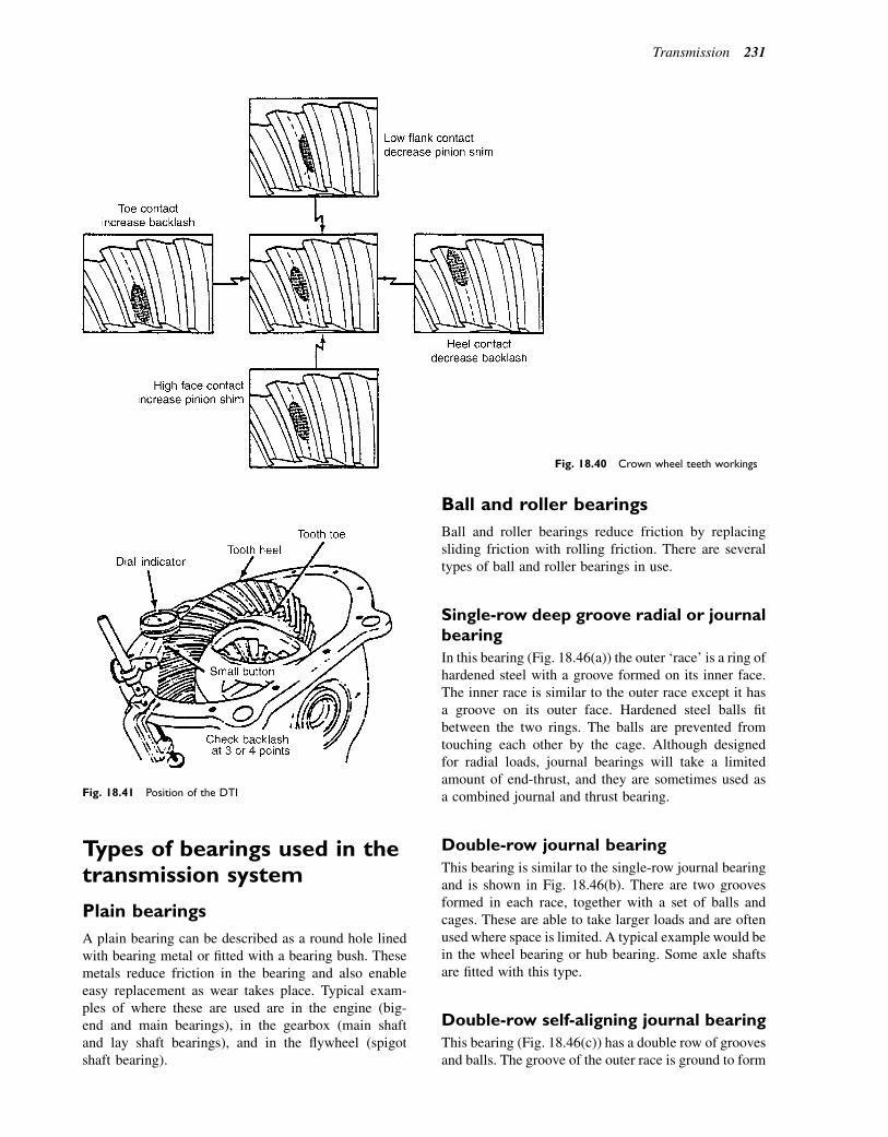
Types of bearings used in thetransmission system
Plain bearings
A plain bearing can be described as a round hole linedwith bearing metal or fitted with a bearing bush. Thesemetals reduce friction in the bearing and also enableeasy replacement as wear takes place. Typical exam-ples of where these are used are in the engine (big-end and main bearings), in the gearbox (main shaftand lay shaft bearings), and in the flywheel (spigotshaft bearing).
Ball and roller bearings
Ball and roller bearings reduce friction by replacingsliding friction with rolling friction. There are severaltypes of ball and roller bearings in use.
Single-row deep groove radial or journalbearing
In this bearing (Fig. 18.46(a)) the outer ‘race’ is a ring ofhardened steel with a groove formed on its inner face.The inner race is similar to the outer race except it hasa groove on its outer face. Hardened steel balls fitbetween the two rings. The balls are prevented fromtouching each other by the cage. Although designedfor radial loads, journal bearings will take a limitedamount of end-thrust, and they are sometimes used asa combined journal and thrust bearing.
Double-row journal bearing
This bearing is similar to the single-row journal bearingand is shown in Fig. 18.46(b). There are two groovesformed in each race, together with a set of balls andcages. These are able to take larger loads and are oftenused where space is limited. A typical example would bein the wheel bearing or hub bearing. Some axle shaftsare fitted with this type.
Double-row self-aligning journal bearing
This bearing (Fig. 18.46(c)) has a double row of groovesand balls. The groove of the outer race is ground to form
Fig. 18.40 Crown wheel teeth workings
Fig. 18.41 Position of the DTI
Transmission 231
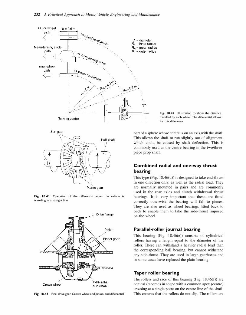
part of a sphere whose centre is on an axis with the shaft.This allows the shaft to run slightly out of alignment,which could be caused by shaft deflection. This iscommonly used as the centre bearing in the two/three-piece prop shaft.
Combined radial and one-way thrustbearing
This type (Fig. 18.46(d)) is designed to take end-thrustin one direction only, as well as the radial load. Theyare normally mounted in pairs and are commonlyused in the rear axles and clutch withdrawal thrustbearings. It is very important that these are fittedcorrectly otherwise the bearing will fall to pieces.They are also used as wheel bearings fitted back toback to enable them to take the side-thrust imposedon the wheel.
Parallel-roller journal bearing
This bearing (Fig. 18.46(e)) consists of cylindricalrollers having a length equal to the diameter of theroller. These can withstand a heavier radial load thanthe corresponding ball bearing, but cannot withstandany side-thrust. They are used in large gearboxes andin some cases have replaced the plain bearing.
Taper roller bearing
The rollers and race of this bearing (Fig. 18.46(f)) areconical (tapered) in shape with a common apex (centre)crossing at a single point on the centre line of the shaft.This ensures that the rollers do not slip. The rollers are
Fig. 18.42 Illustration to show the distance
travelled by each wheel. The differential allows
for this difference
Fig. 18.43 Operation of the differential when the vehicle is
travelling in a straight line
Fig. 18.44 Final drive gear. Crown wheel and pinion, and differential
232 A Practical Approach to Motor Vehicle Engineering and Maintenance
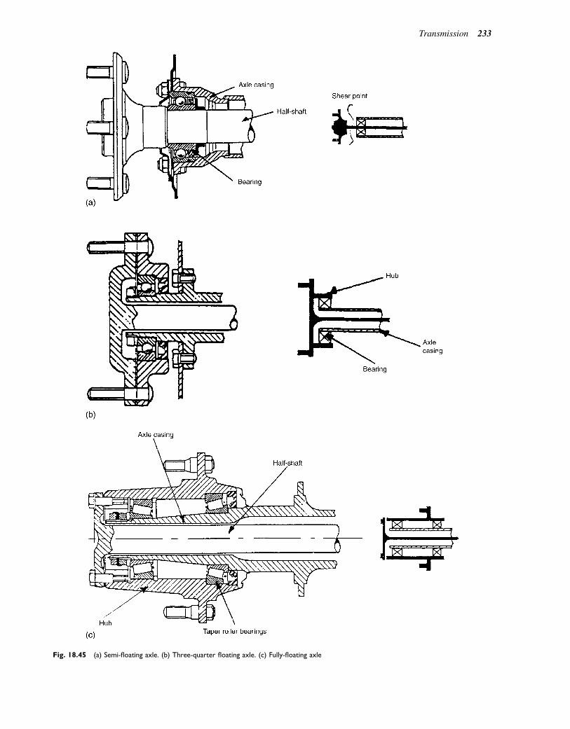
Fig. 18.45 (a) Semi-floating axle. (b) Three-quarter floating axle. (c) Fully-floating axle
Transmission 233

kept in position by flanges on the inner race. This type ofbearing can withstand larger side-thrusts than radialloads and they are normally used in pairs facingeach other. They are most often used in the final drive,rear- and front-wheel hub assemblies. Some formof adjustment is normally used to reduce movementto a minimum or to provide some pre-load to thebearing.
Needle roller bearing
In this bearing (Fig. 18.46(g)) the rollers have a lengthof at least three roller diameters, packed in cagesbetween inner and outer sleeves. The bearings can befound in universal joints and gearboxes, especiallywhere space is limited.
Learning tasks
1. Draw up a simple service schedule for checkingthe axle and final drive for correct operation.Include such things as type, grade and amountof oil used, and time/mileage base for changing/checking oil level.
2. How should the differential be checked forabnormal wear? What would be the main signsof early failure?
3. If a steady whining noise was heard as the vehiclewas driven at a constant speed along a level road,what would you suspect as being the fault andwhat would your recommendations be to put itright?
4. What main safety precautions would you observewhen removing a live axle from a vehicle?
5. Why is it that most vehicles now use the hypoidtype of gearing on the final drive?
6. Draw up the procedure for replacing the half-shafton a live axle; assume the vehicle has been broughtinto the workshop, and the half-shaft has shearedbetween the final drive and the hub bearing.
7. Investigate the differences between a front-engineFWD and a front-engine RWD final drive anddifferential. Itemize the differences in servicingand adjustments that may be necessary whenremoving, stripping, rebuilding, and refitting.
8. An axle requires a new crown and pinion fitting.Remove and dismantle an assembly using theprocedure illustrated in Figs 18.38 and 18.39 togive the correct markings on the gear teeth.
Fig. 18.46 (a) Single-row deep groove radial or journal bearing. (b) Double-row radial or journal bearing. (c) Double-row self-aligning journal
bearing. (d) Radial and one-way thrust bearing. (e) Parallel-roller journal bearing. (f) Taper roller bearing. (g) Needle roller bearing
234 A Practical Approach to Motor Vehicle Engineering and Maintenance

Practical assignment eremoving a clutchWhen completing the task of removing and refitting theclutch, complete the following worksheet.
Questions1. Why are the splines of the gearbox input shaft left
clean and dry and not lubricated with engine oil?2. State the type of clutch spring fitted to the vehicle.3. Make a simple sketch of the clutch release
mechanism. Label your sketch with the maincomponents.
4. Inspect a diaphragm spring clutch assembly whenattached and removed from the flywheel. Sketch theshape (a side view will do) of the diaphragm spring inthe normal run position and in the removed position.
5. State the method used to adjust the clutch and themanufacturer’s recommended clearance.
6. Record the condition of the following components:(a) the driven plate(b) the pressure plate assembly(c) the release bearing and mechanism(d) the oil seals of both the engine and the gearbox.
7. Make your recommendations to the customer togive adequate operation of the clutch for say the next50 000 miles.
Practical assignment eremoving and refittinga gearboxComplete this when undertaking the removal andrefitting of the gearbox.
Questions1. Dismantle a front-engine FWD gearbox. Identify
wear on moving components such as bearings, shafts,gear teeth, thrust washers, and oil seals. List theequipment used to measure this wear.
2. Identify the type of synchromesh unit fitted to thegearbox. From what material is it made?
3. Make a simple sketch of the method used to preventthe engagement of two gears at the same time.When does this unit operate?
4. Sketch and label the position of the selector forks,rails, and location devices. Describe how the gear,once it is engaged, is held in position.
5. Identify first, second, third, fourth, and wherenecessary fifth gear positions. State the gear ratios foreach gear. The formula for calculating gear ratios is:
driven gear
driver gear3
driven gear
driver gear:
6. Reassemble the gearbox and state any specialprecautions to be observed during reassembly andsafety points to look out for.
Practical assignment e axlesand final drivesRemove and dismantle the final drive and differentialunit from a front-engine RWD vehicle.
Questions1. The type of final drive is:
(a) straight bevel(b) spiral bevel(c) hypoid(d) worm and wheel.
2. The bearings used to support the crown wheel are:(a) ball bearing taking axial thrust only(b) taper roller bearings taking axial thrust only(c) ball bearings taking axial and radial thrust(d) taper roller bearings taking axial and radial
thrust.3. Why should the pinion be pre-loaded?4. The type of bearing arrangement supporting the half
shafts is:(a) semi-floating(b) three-quarter floating(c) fully floating(d) a combination of (a), (b) and (c).
5. The axle half-shaft is splined to the:(a) sun gear(b) planet gear(c) crown wheel(d) pinion gear.
6. The type of axle is:(a) split axle(b) live axle(c) dead axle(d) trans-axle.
7. Describe the procedure for reassembling the finaldrive and differential. State the following information:(a) the pre-load on the pinion bearing(b) the tolerance for backlash(c) the torque setting for the pinion nut(d) the final drive ratio(e) the type of oil seal used on the pinion
Transmission 235
(f) the type of oil seal used on the axle half-shaft(g) the type and grade of oil used in the axle(h) the service interval when the oil should be
changed.
Self-assessment questions1. A gearbox ratio of 4:1 means that:(a) the power at the gearbox output shaft is four
times the engine power(b) the power at the gearbox output shaft is
a quarter of the engine power(c) the torque at the gearbox output shaft is four
times the engine torque(d) the speed of the gearbox output shaft is four
times the speed of the engine crankshaft.2. A differential gear in the final drive:(a) allows the wheel on the outside of a bend to
rotate slower than the one on the inside of thebend
(b) prevents skidding during acceleration(c) permit’s the drive to be transmitted through an
angle of 908
(d) allows the wheel on the outside of the bend torotate faster than the one on the inside of thebend.
3. In a synchromesh gearbox:(a) the gears are engaged by sliding them into mesh
as required(b) the gears are engaged by double declutching and
blipping the throttle(c) the gears are engaged by the operation of the
synchromesh units(d) the gears are engaged by the interlock device on
the selector shaft.4. In the Hotchkiss type drive:(a) the distance between the driven axle and the
gearbox remains constant(b) a sliding joint is fitted in the propeller shaft to
allow for variations in the distance between thegearbox and the driven axle
(c) only one Hooke-type coupling is required(d) a torque tube is always required.
5. The technical details of a certain vehicle state thata road speed of 30 mph is achieved when the enginespeed is 2000 rev/min and the vehicle is in top gear.On test, this vehicle achieves 25 mph in top gear
when the tachometer shows an engine speed of2300 rev/min. This is an indication that:(a) the clutch is slipping(b) the engine is producing too much power(c) the driver is using too much throttle(d) the alternator charging rate is too high and it is
causing false speedometer readings.6. In a hypoid bevel final drive:(a) the centre line of the pinion is offset from the
centre line of the crown wheel(b) the drive is transmitted through an angle of 1008
(c) a differential gear is not required(d) the pressure between the gear teeth is very low.
7. In a semi-floating live axle:(a) most of the load is taken by the axle casing(b) shearing and bending forces are carried by the
axle casing(c) most of the load is taken by the axle shaft(d) a shear pin is fitted at the differential end of the
half-shaft.8. The stalling speed of a torque converter is:(a) the speed at which the idle control valve is set to
operate(b) the speed at which torque multiplication is at
a maximum(c) the highest speed that the engine can reach
while the vehicle is in gear and prevented frommoving
(d) lowest speed at which the vehicle can be driven.9. When moving away from a standing start, a torque
converter increases engine torque by a factor of2:1. When the gearbox ratio is 2.5:1 and enginetorque is 100 Nm:(a) the torque at the gearbox output shaft will be
50 Nm(b) the torque at the gearbox output shaft will be
250 kW(c) the torque at the gearbox output shaft will be
500 Nm(d) the torque at the gearbox output shaft will be 4.5
times the engine torque.10. In a fully floating drive axle:
(a) shearing, bending, and torsional forces are alltaken by the axle shafts
(b) a broken axle shaft may cause the wheel to fall off(c) shearing and bending forces are taken by the axle
casing, and torsional forces only are taken by theaxle shafts
(d) the axle has to be dismantled in order to replacea half-shaft.
236 A Practical Approach to Motor Vehicle Engineering and Maintenance

19Electronically controlled automatictransmission
Topics covered in thischapter
Fluid couplingsThe fluid flywheelTorque converterEpicyclic gear trains and ratiosBand brake and clutchesA selection of examples of gear ratiosSensors and actuators used in automatic gearboxoperationThe hydraulic system and its pumps and valvesAutomatic gearbox maintenance e performance checksand maintenance
The details contained in this chapter are intended toprovide a broad overview of the subject that shouldprovide adequate background knowledge for thespecialist training courses that are provided by manufac-turers’ training schools.
The majority of automatic transmission systems ofthe type shown in Fig. 19.1 employ a fluid coupling tomake the connection between the engine and the
gearbox, and an epicyclic gearbox where the gears arechanged without them being taken in and out of mesh.
Fluid couplings
The fluid flywheel
The fluid coupling is called a fluid flywheel because it isnormally attached to the engine flywheel and forms partof it. The fluid flywheel is a sealed container that is filledwith the oil that provides the driving force that operatesthe device when the engine is running. As the impellerrotates, the centrifugal force on the oil in the curvedsegments causes the oil to move to the outer edge ofthe impeller. Because of the speed of rotary motionof the impeller, the oil leaves at an angle; as the oil leavesthe impeller it strikes the curved segments in the turbineand, when the force of the oil is sufficient, it will causethe turbine to rotate. When a gear is engaged the torque(force) on the turbine will gradually increase until it isstrong enough to make the vehicle move. The fluidflywheel is, in effect, an automatic clutch (see Fig. 19.2).
As the rotary speed of the turbine rises, the pressureon the oil in the segments begins to match that of the
Fluid pumpEpicyclic gears – brakes and clutches
Output shaft to drive axle
Oil reservoir
Torque convertor
Input shaft from engine
Fig. 19.1 A typical automatic transmission
� 2011 Allan Bonnick and Derek Newbold. Published by Elsevier Ltd. All rights reserved
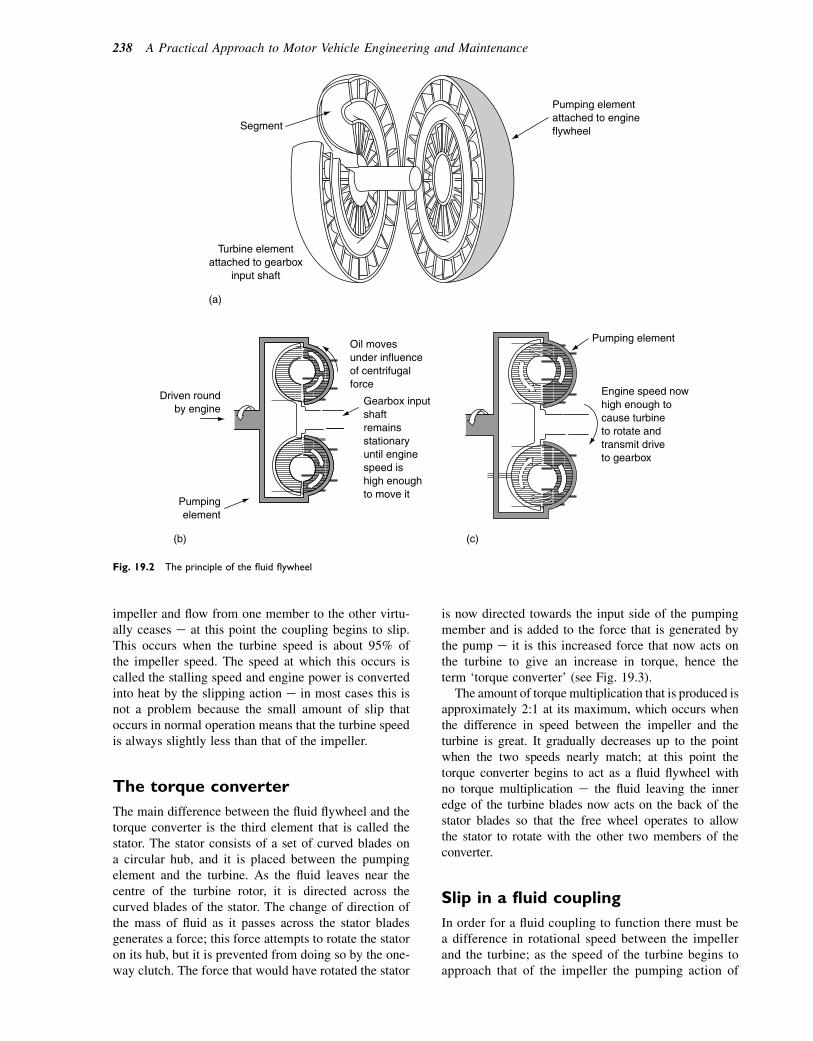
impeller and flow from one member to the other virtu-ally ceases e at this point the coupling begins to slip.This occurs when the turbine speed is about 95% ofthe impeller speed. The speed at which this occurs iscalled the stalling speed and engine power is convertedinto heat by the slipping action e in most cases this isnot a problem because the small amount of slip thatoccurs in normal operation means that the turbine speedis always slightly less than that of the impeller.
The torque converter
The main difference between the fluid flywheel and thetorque converter is the third element that is called thestator. The stator consists of a set of curved blades ona circular hub, and it is placed between the pumpingelement and the turbine. As the fluid leaves near thecentre of the turbine rotor, it is directed across thecurved blades of the stator. The change of direction ofthe mass of fluid as it passes across the stator bladesgenerates a force; this force attempts to rotate the statoron its hub, but it is prevented from doing so by the one-way clutch. The force that would have rotated the stator
is now directed towards the input side of the pumpingmember and is added to the force that is generated bythe pump e it is this increased force that now acts onthe turbine to give an increase in torque, hence theterm ‘torque converter’ (see Fig. 19.3).
The amount of torquemultiplication that is produced isapproximately 2:1 at its maximum, which occurs whenthe difference in speed between the impeller and theturbine is great. It gradually decreases up to the pointwhen the two speeds nearly match; at this point thetorque converter begins to act as a fluid flywheel withno torque multiplication e the fluid leaving the inneredge of the turbine blades now acts on the back of thestator blades so that the free wheel operates to allowthe stator to rotate with the other two members of theconverter.
Slip in a fluid coupling
In order for a fluid coupling to function there must bea difference in rotational speed between the impellerand the turbine; as the speed of the turbine begins toapproach that of the impeller the pumping action of
(a)
Pumping element attached to engine flywheel Segment
Turbine elementattached to gearbox
input shaft
(b)
Oil moves under influence of centrifugal force
Gearbox input shaft remains stationary until engine speed is high enough to move it
Driven round by engine
Pumping element
(c)
Pumping element
Engine speed nowhigh enough tocause turbineto rotate andtransmit driveto gearbox
Fig. 19.2 The principle of the fluid flywheel
238 A Practical Approach to Motor Vehicle Engineering and Maintenance
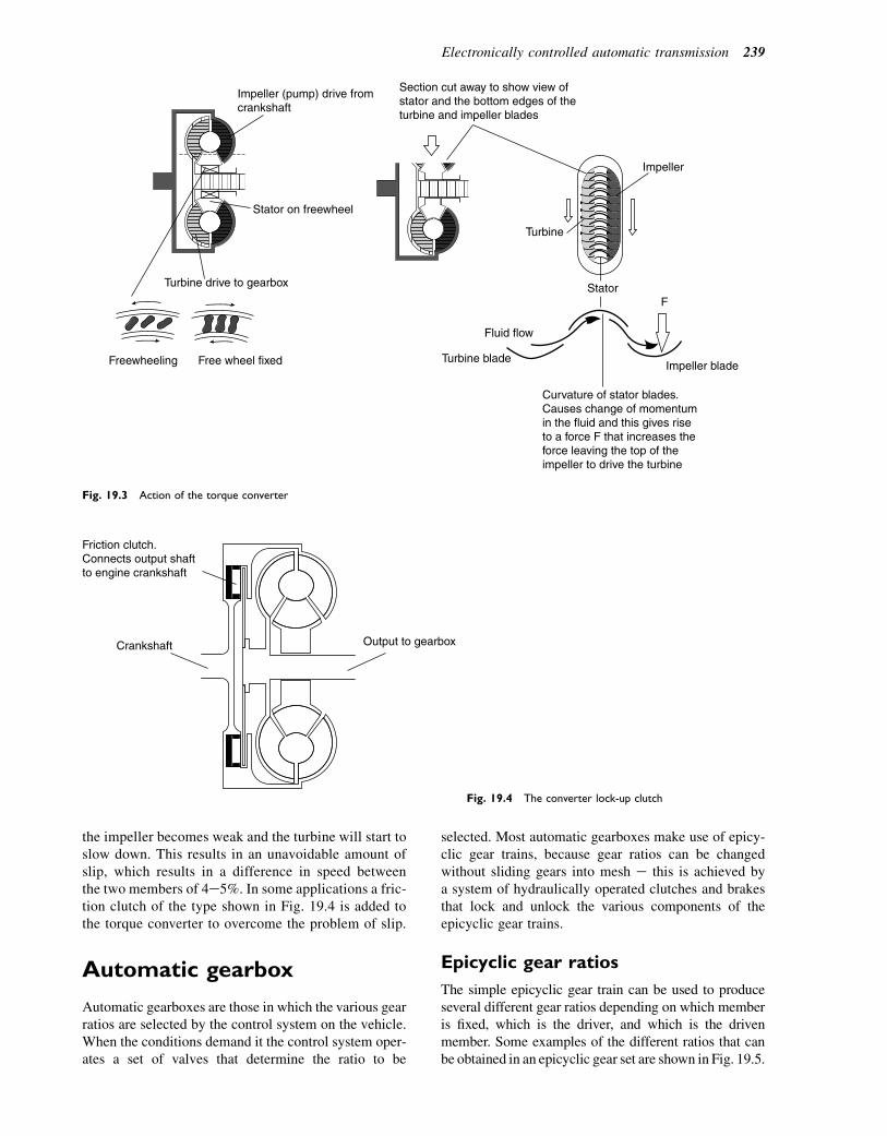
the impeller becomes weak and the turbine will start toslow down. This results in an unavoidable amount ofslip, which results in a difference in speed betweenthe two members of 4e5%. In some applications a fric-tion clutch of the type shown in Fig. 19.4 is added tothe torque converter to overcome the problem of slip.
Automatic gearbox
Automatic gearboxes are those in which the various gearratios are selected by the control system on the vehicle.When the conditions demand it the control system oper-ates a set of valves that determine the ratio to be
selected. Most automatic gearboxes make use of epicy-clic gear trains, because gear ratios can be changedwithout sliding gears into mesh e this is achieved bya system of hydraulically operated clutches and brakesthat lock and unlock the various components of theepicyclic gear trains.
Epicyclic gear ratios
The simple epicyclic gear train can be used to produceseveral different gear ratios depending on which memberis fixed, which is the driver, and which is the drivenmember. Some examples of the different ratios that canbe obtained in an epicyclic gear set are shown in Fig. 19.5.
Impeller (pump) drive fromcrankshaft
Stator on freewheel
Turbine drive to gearbox
Freewheeling Free wheel fixed
Section cut away to show view ofstator and the bottom edges of theturbine and impeller blades
Impeller
Turbine
Fluid flow
Turbine bladeImpeller blade
F
Curvature of stator blades.Causes change of momentumin the fluid and this gives riseto a force F that increases theforce leaving the top of theimpeller to drive the turbine
Stator
Fig. 19.3 Action of the torque converter
Friction clutch.Connects output shaftto engine crankshaft
Crankshaft Output to gearbox
Fig. 19.4 The converter lock-up clutch
Electronically controlled automatic transmission 239
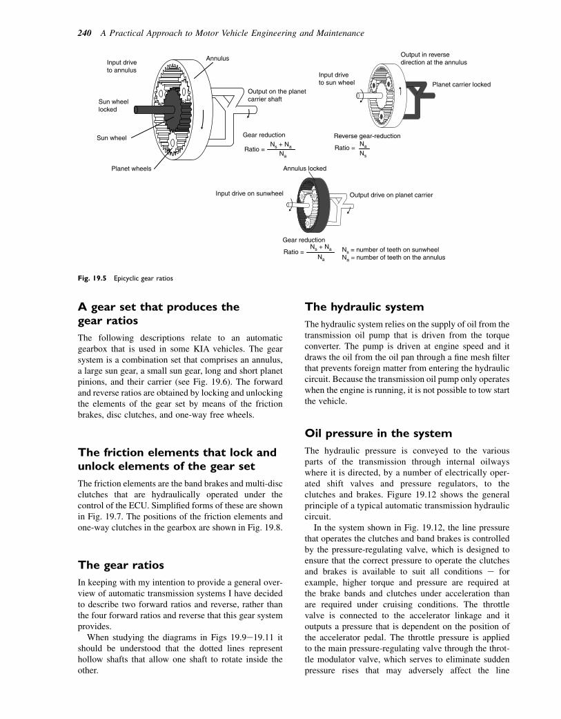
A gear set that produces thegear ratios
The following descriptions relate to an automaticgearbox that is used in some KIA vehicles. The gearsystem is a combination set that comprises an annulus,a large sun gear, a small sun gear, long and short planetpinions, and their carrier (see Fig. 19.6). The forwardand reverse ratios are obtained by locking and unlockingthe elements of the gear set by means of the frictionbrakes, disc clutches, and one-way free wheels.
The friction elements that lock andunlock elements of the gear set
The friction elements are the band brakes and multi-discclutches that are hydraulically operated under thecontrol of the ECU. Simplified forms of these are shownin Fig. 19.7. The positions of the friction elements andone-way clutches in the gearbox are shown in Fig. 19.8.
The gear ratios
In keeping with my intention to provide a general over-view of automatic transmission systems I have decidedto describe two forward ratios and reverse, rather thanthe four forward ratios and reverse that this gear systemprovides.
When studying the diagrams in Figs 19.9e19.11 itshould be understood that the dotted lines representhollow shafts that allow one shaft to rotate inside theother.
The hydraulic system
The hydraulic system relies on the supply of oil from thetransmission oil pump that is driven from the torqueconverter. The pump is driven at engine speed and itdraws the oil from the oil pan through a fine mesh filterthat prevents foreign matter from entering the hydrauliccircuit. Because the transmission oil pump only operateswhen the engine is running, it is not possible to tow startthe vehicle.
Oil pressure in the system
The hydraulic pressure is conveyed to the variousparts of the transmission through internal oilwayswhere it is directed, by a number of electrically oper-ated shift valves and pressure regulators, to theclutches and brakes. Figure 19.12 shows the generalprinciple of a typical automatic transmission hydrauliccircuit.
In the system shown in Fig. 19.12, the line pressurethat operates the clutches and band brakes is controlledby the pressure-regulating valve, which is designed toensure that the correct pressure to operate the clutchesand brakes is available to suit all conditions e forexample, higher torque and pressure are required atthe brake bands and clutches under acceleration thanare required under cruising conditions. The throttlevalve is connected to the accelerator linkage and itoutputs a pressure that is dependent on the position ofthe accelerator pedal. The throttle pressure is appliedto the main pressure-regulating valve through the throt-tle modulator valve, which serves to eliminate suddenpressure rises that may adversely affect the line
Input driveto annulus
Annulus
Annulus locked
Input drive on sunwheel Output drive on planet carrier
Ns = number of teeth on sunwheelNa = number of teeth on the annulus
Output on the planet carrier shaft
Input drive to sun wheel
Output in reverse direction at the annulus
Sun wheellocked
Sun wheel
Planet wheels
Gear reduction Reverse gear-reduction
Ratio =
Gear reduction
Ns + Na
Na
Na
Ns
Planet carrier locked
Ratio =
Ns + Na
Na
Ratio =
Fig. 19.5 Epicyclic gear ratios
240 A Practical Approach to Motor Vehicle Engineering and Maintenance

pressure. At the right-hand end of the pressure-regulating valve is the valve that controls the oil pres-sure in the torque converter, which is normally lower,at approximately 1.5 bar, than the line pressure thatoperates the gear change system.
The shift valves
The shift valves (Fig. 19.13) are controlled by the sole-noid valve that operates under the control of the ECU.
The sensors send information to the ECU, which thencompares them with the operating program to decideon the output that is required. The following descriptionrelates to the procedure for changing gear from first tosecond.
In first gear the solenoid valve is switched off. Linepressure (12) from the regulating valve pushes the shiftvalve to the left, against the pressure from the throttlevalve. This action uncovers the port (9) and releasesthe second gear brake.
Long pinion gear
Long pinion gear
Long pinion gear
Short pinion gear
Short pinion gear
Short pinion gear
Large sun gear
Large sun gear
Small sun gear
Small sun gear
Internal gear
Internal gear
Planetary carrier
Planetary carrier
Output
Fig. 19.6 An epicyclic gear set (KIA)
Annulus
Planet wheels Sun wheel
Hydraulicpressure
Hydraulic pressure fromtransmission oil pump
ServoBand brakeMultiplate clutch
Fixed stop
Brake band
Input shaft
Output shaftPiston
Release spring
Fig. 19.7 Principle used for locking elements of epicyclic gear set
Electronically controlled automatic transmission 241

When a shift from first to second is initiated, the sole-noid valve is opened by the ECU. This allows the linepressure to be diverted from the right-hand end of theshift valve and allows the shift valve to move to theright. Line pressure is now applied to the second gearbrake band while the first gear brake is released. Similaractions apply to the other shift valves that select highergears and reverse.
The sensors
The operation of the shift valves is determined by theECU in response to signals received from the sensors
and driver’s controls. The KIA system that I have out-lined here has the following list of sensors for the auto-matic transmission system:
� Throttle positione creates a voltage that is sent to theECU to represent the position of the acceleratorpedal.
� Idle switch e the signal generated here tells the ECUwhen the throttle is fully closed.
� Pulse generator on the gearbox e sends a signal thatrepresents road speed to the ECU.
� Vehicle speed sensore uses the speedometer readingto act as a check on the pulse generator signal.
Input from torqueconvertor
2-4 brake(B1)
RotationRotation
Multi-plate clutch
Output gear
One-way clutch 1(OWC 1)
Forward clutch (C1)
R
C
S2
P2P1
S1
Fig. 19.8 Multi-plate clutches and brakes in an automatic gearbox (KIA)
One-way clutch 2(OWC 2)
Output gear
Turbine shaft
R
C
Turbine shaft rotates anti-clockwise
Planet carrier C is prevented fromrotating by the action of the oneway clutch 2.
Output gear rotates slower thanturbine shaft input to give reduction
for 1st gear
Small sun gear S2 rotates anti-clockwise
Short planet pinion P rotates clockwise
Long planet pinion P1 rotates anti-clockwise
Planet carrier C rotates clockwise – longpinion P walks around the large sun gearS while rotating anti-clockwise
Forward clutch C applied
One way clutch 1 locked
Fig. 19.9 Obtaining first gear (KIA)
242 A Practical Approach to Motor Vehicle Engineering and Maintenance
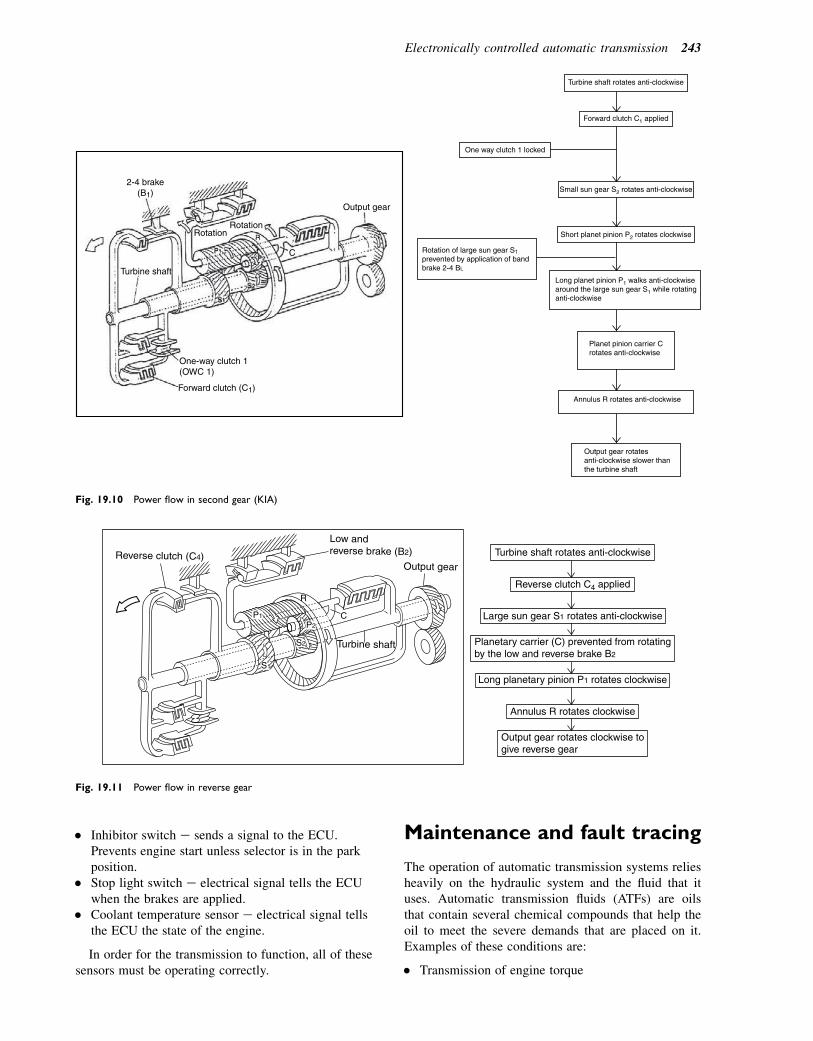
� Inhibitor switch e sends a signal to the ECU.Prevents engine start unless selector is in the parkposition.
� Stop light switch e electrical signal tells the ECUwhen the brakes are applied.
� Coolant temperature sensor e electrical signal tellsthe ECU the state of the engine.
In order for the transmission to function, all of thesesensors must be operating correctly.
Maintenance and fault tracing
The operation of automatic transmission systems reliesheavily on the hydraulic system and the fluid that ituses. Automatic transmission fluids (ATFs) are oilsthat contain several chemical compounds that help theoil to meet the severe demands that are placed on it.Examples of these conditions are:
� Transmission of engine torque
Turbine shaft rotates anti-clockwise
Forward clutch C1 applied
Small sun gear S2 rotates anti-clockwise
Short planet pinion P2 rotates clockwise
Long planet pinion P1 walks anti-clockwisearound the large sun gear S1 while rotatinganti-clockwise
Planet pinion carrier Crotates anti-clockwise
Annulus R rotates anti-clockwise
Output gear rotatesanti-clockwise slower thanthe turbine shaft
One way clutch 1 locked
Rotation of large sun gear S1
prevented by application of bandbrake 2-4 BL
2-4 brake(B1)
Rotation
Turbine shaft
One-way clutch 1(OWC 1)
Forward clutch (C1)
Rotation
Output gear
C
Fig. 19.10 Power flow in second gear (KIA)
Output gear
Turbine shaft
Low andreverse brake (B2)Reverse clutch (C4)
R
C
S2
P2
P1
S1
Turbine shaft rotates anti-clockwise
Large sun gear S1 rotates anti-clockwise
Planetary carrier (C) prevented from rotatingby the low and reverse brake B2
Long planetary pinion P1 rotates clockwise
Annulus R rotates clockwise
Output gear rotates clockwise togive reverse gear
Reverse clutch C4 applied
Fig. 19.11 Power flow in reverse gear
Electronically controlled automatic transmission 243
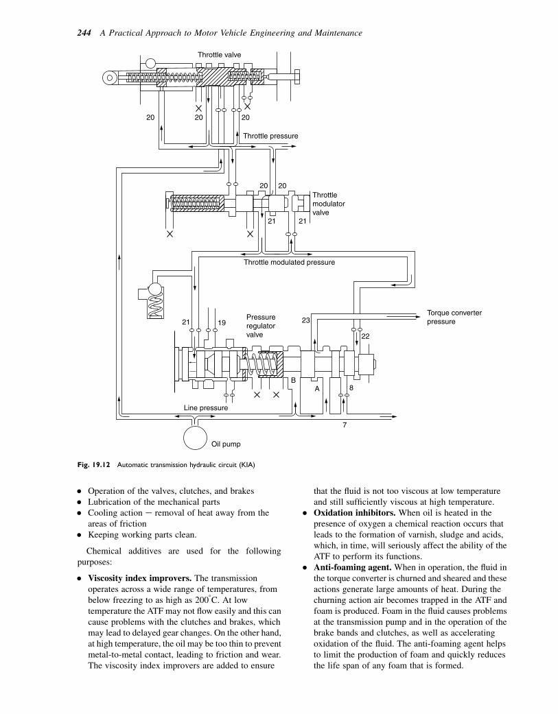
� Operation of the valves, clutches, and brakes� Lubrication of the mechanical parts� Cooling action e removal of heat away from the
areas of friction� Keeping working parts clean.
Chemical additives are used for the followingpurposes:
� Viscosity index improvers. The transmissionoperates across a wide range of temperatures, frombelow freezing to as high as 2008C. At lowtemperature the ATF may not flow easily and this cancause problems with the clutches and brakes, whichmay lead to delayed gear changes. On the other hand,at high temperature, the oil may be too thin to preventmetal-to-metal contact, leading to friction and wear.The viscosity index improvers are added to ensure
that the fluid is not too viscous at low temperatureand still sufficiently viscous at high temperature.
� Oxidation inhibitors. When oil is heated in thepresence of oxygen a chemical reaction occurs thatleads to the formation of varnish, sludge and acids,which, in time, will seriously affect the ability of theATF to perform its functions.
� Anti-foaming agent. When in operation, the fluid inthe torque converter is churned and sheared and theseactions generate large amounts of heat. During thechurning action air becomes trapped in the ATF andfoam is produced. Foam in the fluid causes problemsat the transmission pump and in the operation of thebrake bands and clutches, as well as acceleratingoxidation of the fluid. The anti-foaming agent helpsto limit the production of foam and quickly reducesthe life span of any foam that is formed.
Throttle valve
Throttle pressure
Throttle modulated pressure
Throttlemodulatorvalve
20
20
2121
21 19 23
22
8AB
7
Oil pump
Line pressure
Pressureregulatorvalve
Torque converterpressure
20
2020
Fig. 19.12 Automatic transmission hydraulic circuit (KIA)
244 A Practical Approach to Motor Vehicle Engineering and Maintenance
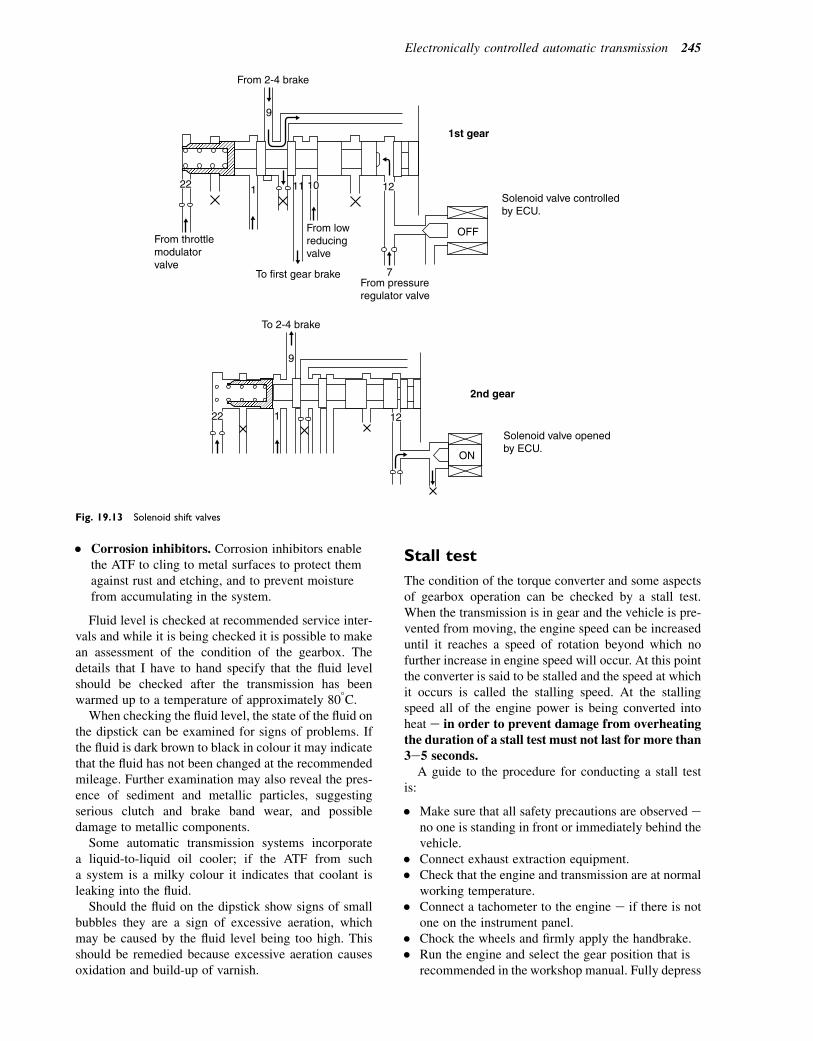
� Corrosion inhibitors. Corrosion inhibitors enablethe ATF to cling to metal surfaces to protect themagainst rust and etching, and to prevent moisturefrom accumulating in the system.
Fluid level is checked at recommended service inter-vals and while it is being checked it is possible to makean assessment of the condition of the gearbox. Thedetails that I have to hand specify that the fluid levelshould be checked after the transmission has beenwarmed up to a temperature of approximately 808C.
When checking the fluid level, the state of the fluid onthe dipstick can be examined for signs of problems. Ifthe fluid is dark brown to black in colour it may indicatethat the fluid has not been changed at the recommendedmileage. Further examination may also reveal the pres-ence of sediment and metallic particles, suggestingserious clutch and brake band wear, and possibledamage to metallic components.
Some automatic transmission systems incorporatea liquid-to-liquid oil cooler; if the ATF from sucha system is a milky colour it indicates that coolant isleaking into the fluid.
Should the fluid on the dipstick show signs of smallbubbles they are a sign of excessive aeration, whichmay be caused by the fluid level being too high. Thisshould be remedied because excessive aeration causesoxidation and build-up of varnish.
Stall test
The condition of the torque converter and some aspectsof gearbox operation can be checked by a stall test.When the transmission is in gear and the vehicle is pre-vented from moving, the engine speed can be increaseduntil it reaches a speed of rotation beyond which nofurther increase in engine speed will occur. At this pointthe converter is said to be stalled and the speed at whichit occurs is called the stalling speed. At the stallingspeed all of the engine power is being converted intoheat e in order to prevent damage from overheatingthe duration of a stall test must not last for more than3e5 seconds.
A guide to the procedure for conducting a stall testis:
� Make sure that all safety precautions are observed eno one is standing in front or immediately behind thevehicle.
� Connect exhaust extraction equipment.� Check that the engine and transmission are at normal
working temperature.� Connect a tachometer to the engine e if there is not
one on the instrument panel.� Chock the wheels and firmly apply the handbrake.� Run the engine and select the gear position that is
recommended in the workshop manual. Fully depress
From 2-4 brake
To 2-4 brake
9
From throttlemodulatorvalve
From lowreducingvalve
From pressureregulator valve
1st gear
2nd gear
1 11
7To first gear brake
OFF
Solenoid valve controlled by ECU.
Solenoid valve opened by ECU.
ON
9
1
22 10 12
22 12
Fig. 19.13 Solenoid shift valves
Electronically controlled automatic transmission 245
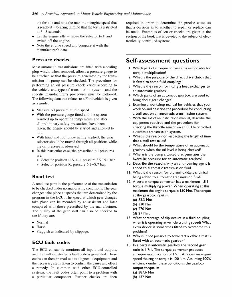
the throttle and note the maximum engine speed thatis reached e bearing in mind that the test is restrictedto 3e5 seconds.
� Let the engine idle e move the selector to P andswitch off the engine.
� Note the engine speed and compare it with themanufacturer’s data.
Pressure checks
Most automatic transmissions are fitted with a sealingplug which, when removed, allows a pressure gauge tobe attached so that the pressure generated by the trans-mission oil pump can be checked. The procedure forperforming an oil pressure check varies according tothe vehicle and type of transmission system, and thespecific manufacturer’s procedures must be followed.The following data that relates to a Ford vehicle is givenas a guide:
� Measure oil pressure at idle speed.� With the pressure gauge fitted and the system
warmed up to operating temperature and afterall preliminary safety precautions have beentaken, the engine should be started and allowed toidle.
� With hand and foot brake firmly applied, the gearselector should be moved through all positions whilethe oil pressure is observed.
� In this particular case, the prescribed oil pressuresare:� Selector position P-N-D-l, pressure 3.9e5.1 bar� Selector position R, pressure 6.2e8.7 bar.
Road test
A road test permits the performance of the transmissionto be checked under normal driving conditions. The gearchanges take place at speeds that are determined by theprogram in the ECU. The speed at which gear changestake place can be recorded by an assistant and latercompared with those prescribed by the manufacturer.The quality of the gear shift can also be checked tosee if they are:
� Normal� Harsh� Sluggish as indicated by slippage.
ECU fault codes
The ECU constantly monitors all inputs and outputs,and if a fault is detected a fault code is generated. Thesecodes can then be read out to diagnostic equipment andthe necessary steps taken to confirm the cause and effecta remedy. In common with other ECU-controlledsystems, the fault codes often point to a problem witha particular component. Further checks are then
required in order to determine the precise cause sothat a decision as to whether to repair or replace canbe made. Examples of sensor checks are given in thesection of the book that is devoted to the subject of elec-tronically controlled systems.
Self-assessment questions1. Which part of a torque converter is responsible for
torque multiplication?2. What is the purpose of the direct drive clutch that
is fitted to some fluid couplings?3. What is the reason for fitting a heat exchanger to
an automatic gearbox?4. Which parts of an automatic gearbox are used to
bring about gear changes?5. Examine a workshop manual for vehicles that you
work on and describe the procedure for conductinga stall test on an automatic transmission system.
6. With the aid of an instruction manual, describe theequipment required and the procedure forchecking the throttle sensor on an ECU-controlledautomatic transmission system.
7. What is the reason for restricting the length of timethat a stall test takes?
8. What should be the temperature of an automaticgearbox when the oil level is being checked?
9. Where is the pump situated that generates thehydraulic pressure for an automatic gearbox?
10. Describe the reasons why an anti-foaming agent isadded to automatic transmission fluid.
11. What is the reason for the anti-oxidant chemicalbeing added to automatic transmission fluid?
12. A certain torque converter has a maximum 1.8:1torque multiplying power. When operating at thismaximum the engine torque is 150 Nm. The torqueat the gearbox input is:(a) 83.3 Nm(b) 330 Nm(c) 270 Nm(d) 27 Nm.
13. What percentage of slip occurs in a fluid couplingwhen it is operating at vehicle cruising speed? Whatextra device is sometimes fitted to overcome thisproblem?
14. Why is it not possible to tow-start a vehicle that isfitted with an automatic gearbox?
15. In a certain automatic gearbox the second gearratio is 1.7:1. The torque converter producesa torque multiplication of 1.9:1. At a certain enginespeed the engine torque is 120 Nm. Assuming 100%efficiency under these conditions, the gearboxoutput torque is:(a) 387.6 Nm(b) 432 Nm
246 A Practical Approach to Motor Vehicle Engineering and Maintenance

(c) 33.3 Nm(d) 37.15 Nm.
16. Which valve regulates the hydraulic pressure in anautomatic transmission system?
17. How are the shift valves operated in an ECU-controlled automatic transmission?
18. What is the purpose of the throttle position sensorin an ECU-controlled automatic transmission?
19. How does the ECU know when the vehicle brakesare being operated?
20. What is the purpose of the speed sensor that isfitted in the automatic gearbox?
Electronically controlled automatic transmission 247
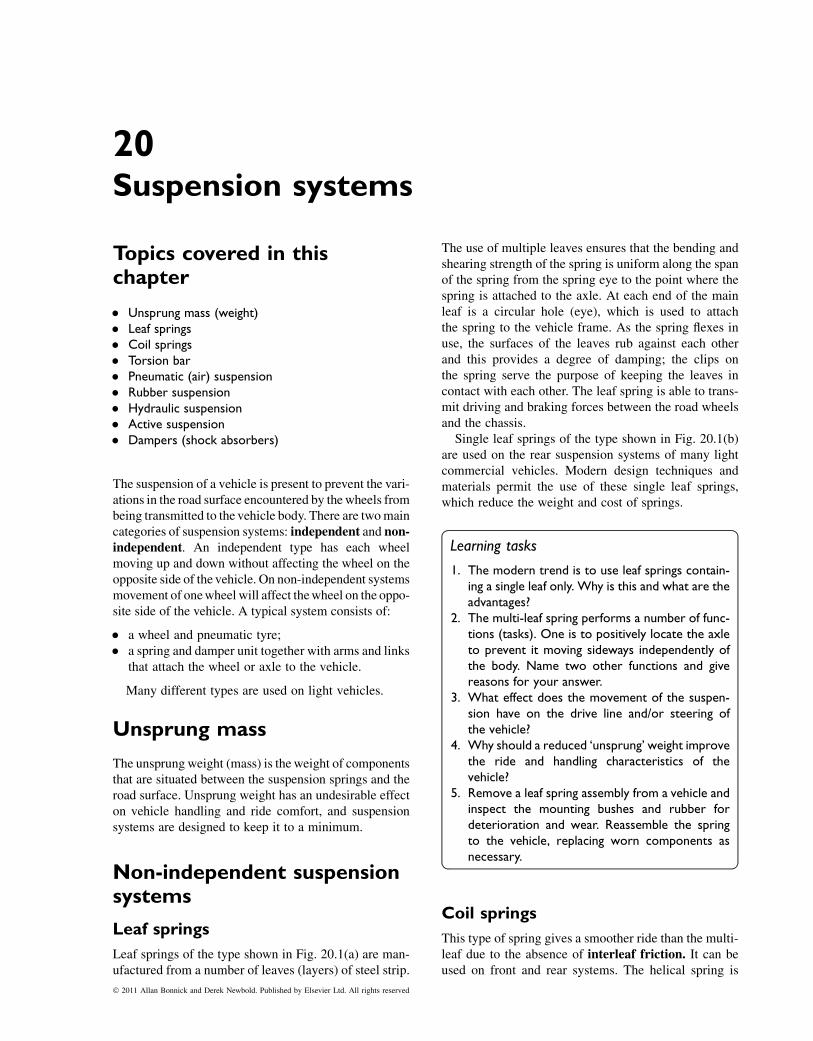
20Suspension systems
Topics covered in thischapter
� Unsprung mass (weight)� Leaf springs� Coil springs� Torsion bar� Pneumatic (air) suspension� Rubber suspension� Hydraulic suspension� Active suspension� Dampers (shock absorbers)
The suspension of a vehicle is present to prevent the vari-ations in the road surface encountered by thewheels frombeing transmitted to the vehicle body. There are twomaincategories of suspension systems: independent and non-independent. An independent type has each wheelmoving up and down without affecting the wheel on theopposite side of the vehicle. On non-independent systemsmovement of onewheel will affect thewheel on the oppo-site side of the vehicle. A typical system consists of:
� a wheel and pneumatic tyre;� a spring and damper unit together with arms and links
that attach the wheel or axle to the vehicle.
Many different types are used on light vehicles.
Unsprung mass
The unsprung weight (mass) is the weight of componentsthat are situated between the suspension springs and theroad surface. Unsprung weight has an undesirable effecton vehicle handling and ride comfort, and suspensionsystems are designed to keep it to a minimum.
Non-independent suspensionsystems
Leaf springs
Leaf springs of the type shown in Fig. 20.1(a) are man-ufactured from a number of leaves (layers) of steel strip.
The use of multiple leaves ensures that the bending andshearing strength of the spring is uniform along the spanof the spring from the spring eye to the point where thespring is attached to the axle. At each end of the mainleaf is a circular hole (eye), which is used to attachthe spring to the vehicle frame. As the spring flexes inuse, the surfaces of the leaves rub against each otherand this provides a degree of damping; the clips onthe spring serve the purpose of keeping the leaves incontact with each other. The leaf spring is able to trans-mit driving and braking forces between the road wheelsand the chassis.
Single leaf springs of the type shown in Fig. 20.1(b)are used on the rear suspension systems of many lightcommercial vehicles. Modern design techniques andmaterials permit the use of these single leaf springs,which reduce the weight and cost of springs.
Learning tasks
1. The modern trend is to use leaf springs contain-ing a single leaf only. Why is this and what are theadvantages?
2. The multi-leaf spring performs a number of func-tions (tasks). One is to positively locate the axleto prevent it moving sideways independently ofthe body. Name two other functions and givereasons for your answer.
3. What effect does the movement of the suspen-sion have on the drive line and/or steering ofthe vehicle?
4. Why should a reduced ‘unsprung’ weight improvethe ride and handling characteristics of thevehicle?
5. Remove a leaf spring assembly from a vehicle andinspect the mounting bushes and rubber fordeterioration and wear. Reassemble the springto the vehicle, replacing worn components asnecessary.
Coil springs
This type of spring gives a smoother ride than the multi-leaf due to the absence of interleaf friction. It can beused on front and rear systems. The helical spring is
� 2011 Allan Bonnick and Derek Newbold. Published by Elsevier Ltd. All rights reserved
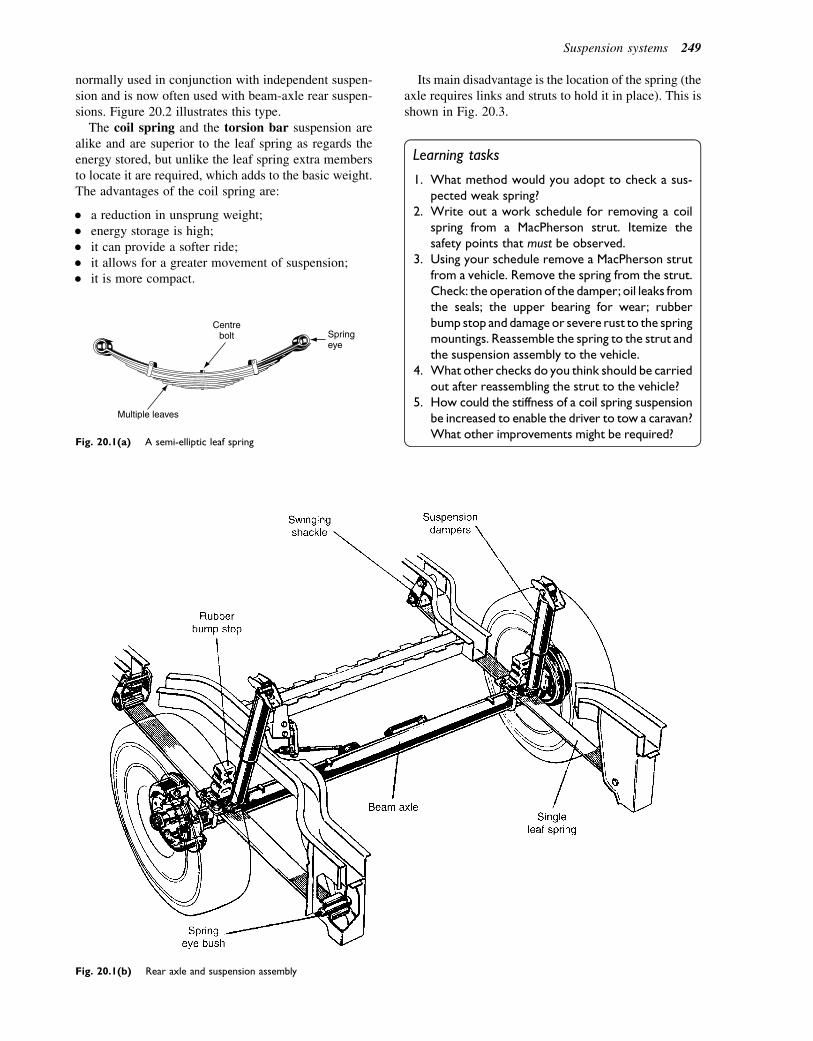
normally used in conjunction with independent suspen-sion and is now often used with beam-axle rear suspen-sions. Figure 20.2 illustrates this type.
The coil spring and the torsion bar suspension arealike and are superior to the leaf spring as regards theenergy stored, but unlike the leaf spring extra membersto locate it are required, which adds to the basic weight.The advantages of the coil spring are:
� a reduction in unsprung weight;� energy storage is high;� it can provide a softer ride;� it allows for a greater movement of suspension;� it is more compact.
Its main disadvantage is the location of the spring (theaxle requires links and struts to hold it in place). This isshown in Fig. 20.3.
Learning tasks
1. What method would you adopt to check a sus-pected weak spring?
2. Write out a work schedule for removing a coilspring from a MacPherson strut. Itemize thesafety points that must be observed.
3. Using your schedule remove a MacPherson strutfrom a vehicle. Remove the spring from the strut.Check: the operation of the damper; oil leaks fromthe seals; the upper bearing for wear; rubberbump stop and damage or severe rust to the springmountings. Reassemble the spring to the strut andthe suspension assembly to the vehicle.
4. What other checks do you think should be carriedout after reassembling the strut to the vehicle?
5. How could the stiffness of a coil spring suspensionbe increased to enable the driver to tow a caravan?What other improvements might be required?
Multiple leaves
Centre bolt Spring
eye
Fig. 20.1(a) A semi-elliptic leaf spring
Fig. 20.1(b) Rear axle and suspension assembly
Suspension systems 249
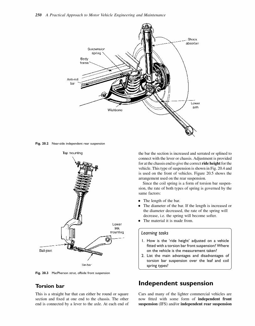
Torsion bar
This is a straight bar that can either be round or squaresection and fixed at one end to the chassis. The otherend is connected by a lever to the axle. At each end of
the bar the section is increased and serrated or splined toconnect with the lever or chassis. Adjustment is providedfor at the chassis end to give the correct ride height for thevehicle. This type of suspension is shown in Fig. 20.4 andis used on the front of vehicles. Figure 20.5 shows thearrangement used on the rear suspension.
Since the coil spring is a form of torsion bar suspen-sion, the rate of both types of spring is governed by thesame factors:
� The length of the bar.� The diameter of the bar. If the length is increased or
the diameter decreased, the rate of the spring willdecrease, i.e. the spring will become softer.
� The material it is made from.
Learning tasks
1. How is the ‘ride height’ adjusted on a vehiclefitted with a torsion bar front suspension?Whereon the vehicle is the measurement taken?
2. List the main advantages and disadvantages oftorsion bar suspension over the leaf and coilspring types?
Independent suspension
Cars and many of the lighter commercial vehicles arenow fitted with some form of independent frontsuspension (IFS) and/or independent rear suspension
Fig. 20.2 Near-side independent rear suspension
Fig. 20.3 MacPherson strut, offside front suspension
250 A Practical Approach to Motor Vehicle Engineering and Maintenance

Fig. 20.4 Torsion-bar double-transverse-arm independent front suspension. (a) Pictorial view. (b) Section viewe lower-suspension-armpivot assembly
Fig. 20.5 Transverse torsion bar rear suspension
Suspension systems 251
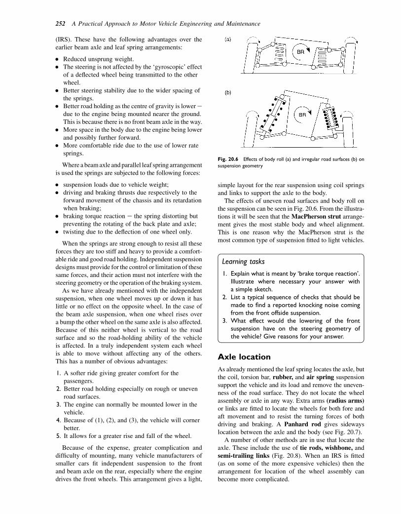
(IRS). These have the following advantages over theearlier beam axle and leaf spring arrangements:
� Reduced unsprung weight.� The steering is not affected by the ‘gyroscopic’ effect
of a deflected wheel being transmitted to the otherwheel.
� Better steering stability due to the wider spacing ofthe springs.
� Better road holding as the centre of gravity is loweredue to the engine being mounted nearer the ground.This is because there is no front beam axle in the way.
� More space in the body due to the engine being lowerand possibly further forward.
� More comfortable ride due to the use of lower ratesprings.
Where a beamaxle and parallel leaf spring arrangementis used the springs are subjected to the following forces:
� suspension loads due to vehicle weight;� driving and braking thrusts due respectively to the
forward movement of the chassis and its retardationwhen braking;
� braking torque reaction e the spring distorting butpreventing the rotating of the back plate and axle;
� twisting due to the deflection of one wheel only.
When the springs are strong enough to resist all theseforces they are too stiff and heavy to provide a comfort-able ride and good road holding. Independent suspensiondesignsmust provide for the control or limitation of thesesame forces, and their action must not interfere with thesteering geometry or the operation of the braking system.
As we have already mentioned with the independentsuspension, when one wheel moves up or down it haslittle or no effect on the opposite wheel. In the case ofthe beam axle suspension, when one wheel rises overa bump the other wheel on the same axle is also affected.Because of this neither wheel is vertical to the roadsurface and so the road-holding ability of the vehicleis affected. In a truly independent system each wheelis able to move without affecting any of the others.This has a number of obvious advantages:
1. A softer ride giving greater comfort for thepassengers.
2. Better road holding especially on rough or unevenroad surfaces.
3. The engine can normally be mounted lower in thevehicle.
4. Because of (1), (2), and (3), the vehicle will cornerbetter.
5. It allows for a greater rise and fall of the wheel.
Because of the expense, greater complication anddifficulty of mounting, many vehicle manufacturers ofsmaller cars fit independent suspension to the frontand beam axle on the rear, especially where the enginedrives the front wheels. This arrangement gives a light,
simple layout for the rear suspension using coil springsand links to support the axle to the body.
The effects of uneven road surfaces and body roll onthe suspension can be seen in Fig. 20.6. From the illustra-tions it will be seen that the MacPherson strut arrange-ment gives the most stable body and wheel alignment.This is one reason why the MacPherson strut is themost common type of suspension fitted to light vehicles.
Learning tasks
1. Explain what is meant by ‘brake torque reaction’.Illustrate where necessary your answer witha simple sketch.
2. List a typical sequence of checks that should bemade to find a reported knocking noise comingfrom the front offside suspension.
3. What effect would the lowering of the frontsuspension have on the steering geometry ofthe vehicle? Give reasons for your answer.
Axle location
As already mentioned the leaf spring locates the axle, butthe coil, torsion bar, rubber, and air spring suspensionsupport the vehicle and its load and remove the uneven-ness of the road surface. They do not locate the wheelassembly or axle in any way. Extra arms (radius arms)or links are fitted to locate the wheels for both fore andaft movement and to resist the turning forces of bothdriving and braking. A Panhard rod gives sidewayslocation between the axle and the body (see Fig. 20.7).
A number of other methods are in use that locate theaxle. These include the use of tie rods, wishbone, andsemi-trailing links (Fig. 20.8). When an IRS is fitted(as on some of the more expensive vehicles) then thearrangement for location of the wheel assembly canbecome more complicated.
Fig. 20.6 Effects of body roll (a) and irregular road surfaces (b) on
suspension geometry
252 A Practical Approach to Motor Vehicle Engineering and Maintenance
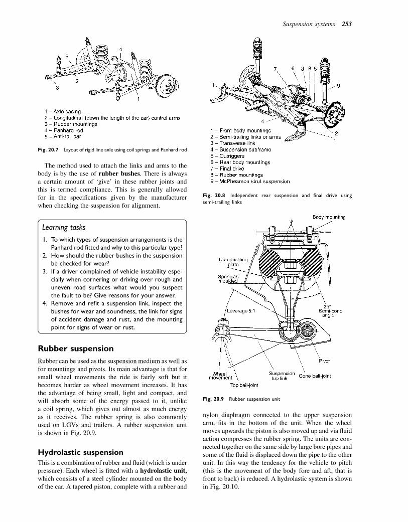
The method used to attach the links and arms to thebody is by the use of rubber bushes. There is alwaysa certain amount of ‘give’ in these rubber joints andthis is termed compliance. This is generally allowedfor in the specifications given by the manufacturerwhen checking the suspension for alignment.
Learning tasks
1. To which types of suspension arrangements is thePanhard rod fitted and why to this particular type?
2. How should the rubber bushes in the suspensionbe checked for wear?
3. If a driver complained of vehicle instability espe-cially when cornering or driving over rough anduneven road surfaces what would you suspectthe fault to be? Give reasons for your answer.
4. Remove and refit a suspension link, inspect thebushes for wear and soundness, the link for signsof accident damage and rust, and the mountingpoint for signs of wear or rust.
Rubber suspension
Rubber can be used as the suspension medium as well asfor mountings and pivots. Its main advantage is that forsmall wheel movements the ride is fairly soft but itbecomes harder as wheel movement increases. It hasthe advantage of being small, light and compact, andwill absorb some of the energy passed to it, unlikea coil spring, which gives out almost as much energyas it receives. The rubber spring is also commonlyused on LGVs and trailers. A rubber suspension unitis shown in Fig. 20.9.
Hydrolastic suspension
This is a combination of rubber and fluid (which is underpressure). Each wheel is fitted with a hydrolastic unit,which consists of a steel cylinder mounted on the bodyof the car. A tapered piston, complete with a rubber and
nylon diaphragm connected to the upper suspensionarm, fits in the bottom of the unit. When the wheelmoves upwards the piston is also moved up and via fluidaction compresses the rubber spring. The units are con-nected together on the same side by large bore pipes andsome of the fluid is displaced down the pipe to the otherunit. In this way the tendency for the vehicle to pitch(this is the movement of the body fore and aft, that isfront to back) is reduced. A hydrolastic system is shownin Fig. 20.10.
Fig. 20.7 Layout of rigid line axle using coil springs and Panhard rod
Fig. 20.8 Independent rear suspension and final drive using
semi-trailing links
Fig. 20.9 Rubber suspension unit
Suspension systems 253
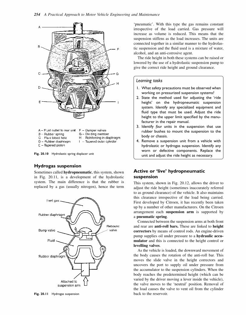
Hydrogas suspension
Sometimes called hydropneumatic, this system, shownin Fig. 20.11, is a development of the hydrolasticsystem. The main difference is that the rubber isreplaced by a gas (usually nitrogen), hence the term
‘pneumatic’. With this type the gas remains constantirrespective of the load carried. Gas pressure willincrease as volume is reduced. This means that thesuspension stiffens as the load increases. The units areconnected together in a similar manner to the hydrolas-tic suspension and the fluid used is a mixture of water,alcohol, and an anti-corrosive agent.
The ride height in both these systems can be raised orlowered by the use of a hydrolastic suspension pump togive the correct ride height and ground clearance.
Learning tasks
1. What safety precautions must be observed whenworking on pressurized suspension systems?
2. State the method used for adjusting the ‘rideheight’ on the hydropneumatic suspensionsystem. Identify any specialized equipment andfluid type that must be used. Adjust the rideheight to the upper limit specified by the manu-facturer in the repair manual.
3. Identify four units in the suspension that userubber bushes to mount the suspension to thebody or chassis.
4. Remove a suspension unit from a vehicle withhydrolastic or hydrogas suspension. Identify anyworn or defective components. Replace theunit and adjust the ride height as necessary.
Active or ‘live’ hydropneumaticsuspension
This system, shown in Fig. 20.12, allows the driver toadjust the ride height (sometimes inaccurately referredto as ground clearance) of the vehicle. It also maintainsthis clearance irrespective of the load being carried.First developed by Citroen, it has recently been takenup by a number of other manufacturers. On the Citroenarrangement each suspension arm is supported bya pneumatic spring.
Connected between the suspension arms at both frontand rear are anti-roll bars. These are linked to heightcorrectors by means of control rods. An engine-drivenpump supplies oil under pressure to a hydraulic accu-mulator and this is connected to the height control orlevelling valves.
As the vehicle is loaded, the downward movement ofthe body causes the rotation of the anti-roll bar. Thismoves the slide valve in the height correctors anduncovers the port to supply oil under pressure fromthe accumulator to the suspension cylinders. When thebody reaches the predetermined height (which can bevaried by the driver moving a lever inside the vehicle),the valve moves to the ‘neutral’ position. Removal ofthe load causes the valve to vent oil from the cylinderback to the reservoir.
Fig. 20.10 Hydrolastic spring displacer unit
Fig. 20.11 Hydrogas suspension
254 A Practical Approach to Motor Vehicle Engineering and Maintenance

A delay device is incorporated to prevent rapid oilflow past the valve when the wheel contacts a bump.This prevents the valve from continuously workingand giving unsatisfactory operation.
In some systems a third spring unit is fitted betweenthe two spring units on the front axle and between thetwo spring units on the rear axle. This gives a variablespring rate and roll stiffness, i.e. the suspension is active.The system is controlled by an ECU (electronic controlunit), which senses steering wheel movement, accelera-tion, speed and body movement, and reacts accordinglyvia control valves to regulate the flow of oil to andfrom the suspension units. Under normal driving condi-tions the ECU operates the solenoid valve, which directsfluid to open the regulator valves. This allows fluid toflow between the two outer spring units and the thirdspring units via the damper units to give a soft ride.During harder driving the solenoid valve is switchedoff automatically, relieving the regulator valves whichclose, preventing fluid flow between the spring units,The third spring unit, being isolated and not in use, givesa firmer ride.
There are a number of benefits of this system:
� It automatically adjusts the spring and damper rate tosuit road conditions and driving styles.
� It can provide a soft and comfortable ride undernormal driving conditions.
� It will stiffen to give better road holding during harddriving.
� A near-constant ride height can be achievedirrespective of the load on the vehicle.
Learning tasks
1. A number of safety precautions must beobserved before dismantling this type of suspen-sion system. What are these and why should theybe carried out?
2. What are the main advantages/disadvantages ofthis type of suspension system over a mechanicalsystem?
3. The oil in the system should be changed at regularintervals. How often is this and what is thecorrect procedure? State the correct type of fluidthat must be used in the system.
4. Remove and refit a hydropneumatic suspensionunit. Take care when undoing pipe unions thatthe pipes are not damaged. Observe all the safetyprecautions necessary. Make a note of all defects,re-pressurize the system, and check for leaks.
Rear wheel ‘suspension steer’
In some systems the rear suspension is arranged toproduce a steering effect when cornering. As the suspen-sion is deflected the road wheel toes-in due to the arc ofmovement of the semi-trailing link. This producesundersteer on cornering (it gives a small degree ofsame direction rear-steer). Figure 20.13 shows oneexample that will give:
� toe-in when braking;� understeer when cornering;� stability in straight-line running and when changing
lanes.
A simpler suspension arrangement is shown inFig. 20.14 that produces toe-in under similar operatingconditions.
Air suspension
Some vehicle manufacturers fit air suspension units inplace of the conventional coil springs. A typicalexample with electronically controlled air suspensionis shown in Fig. 20.15. Three switches, positionednear the steering column, control the ride height: the
Fig. 20.12 Simplified layout of a hydropneumatic suspension system
Suspension systems 255

upper switch raises the vehicle by approximately 40 mmfor driving through deep water or over rough ground; themiddle switch gives a similar ride height to the coil-sprung model; the lower switch lowers the vehicleapproximately 60 mm below the standard setting toenable easier loading and for getting in and out. Anumber of automatic adjustments such as lowering thevehicle when driving over 50mph to reduce wind resis-tance and raising the vehicle if it should becomegrounded are programmed into the ECU and operateindependently of the driver.
Another system uses a digital controller (ECU),which reacts to suspension acceleration and ride heightby varying the oil pressure. It will also adjust damperaction by reference to body movement.
Some manufacturers make ride height levellers(Fig. 20.16), which are shock absorbers that will raisethe rear of the vehicle to its normal ride height whenloaded. The system is operated through a switch, elec-tric motor, and compressor; the dampers are pumpedup via air pipes connecting the units together.
The suspension damper has to perform a number offunctions. These are:
� absorb road surface variations;� insulate the noise from the vehicle body;� give resistance to vehicle body pitch under braking
and acceleration;� offer resistance to roll when cornering.
A passive mechanical system to tackle each of thesetasks is impossible as the rate of the damper must bevaried to suit differing circumstances and handling char-acteristics. Shock-absorber manufacturers have madeprovision for some control over the damping rate bymaking them adjustable, but once set even these arenot suitable for all applications and uses.
With this in mind many of the new suspensionsystems are active; in other words they will operatecontinuously, adjusting to preset limits the suspensionspring rate. One system uses an ECU that receives infor-mation on cruising, suspension condition, body roll, andpitch. It then directs air from the compressor to thesuspension units to give the correct spring rate andride height for the load carried.
Learning tasks
1. What is the purpose of the ECU and electronicsensors in an active suspension system? Whatattention do these units require and at whatintervals should checks be carried out?
2. On some models the system is connected to theanti-lock braking system. Explain in simple termsthe reason for this and how it operates.
3. List the maintenance requirements for one of the‘active’ suspension systems with which you arefamiliar.
Fig. 20.13 Multi-link rear suspension
256 A Practical Approach to Motor Vehicle Engineering and Maintenance

4. Draw up a work schedule for removing a suspen-sion unit from a vehicle. Special note should bemade of the safety aspects of the task.
5. Remove an ECU from an active suspensionsystem, check the terminals for corrosion ordamage, and clean with appropriate spray cleanerwhere necessary. Ensure that the mountingsurface is clean and free from rust. Refit theECU taking special care when refitting theterminal connector.
Suspension dampers
The function of the suspension damper is not to increasethe resistance to the spring deflecting but to control the
oscillation of the spring (this is the continuing up anddown movement of the spring after going over a bumpor hollow in the road surface). In other words it absorbsenergy given to the spring, hence the more commonname of shock absorber. It does this by forcing oil inthe damper to do work by passing it through holes inthe piston and converting the energy of the movingspring into heat, which is passed to the atmosphere.
Two main categories of dampers are in commonuse: the direct-acting (usually telescopic) and thelever arm.
The twin-tube telescopic damper
This type is usually located between the chassis and theaxle so that on both bump and rebound oil is forcedthrough the holes in the piston. The reservoir is used to
Fig. 20.14 Multi-link rear suspension giving toe-in during braking and cornering
Suspension systems 257

accommodate the excess oil that is displaced as a result ofthe volume in the upper cylinder being smaller. If oil islost and air enters the damper it will affect its performanceand it will become ‘spongy’ in operation. This will havean effect on the stability of the vehicle, especially whencornering, travelling over rough ground, uneven surfaces,and on braking or accelerating.When checking for correctoperation disconnect one end of the damper and check theamount of resistance to movement. Figure 20.17 showsa telescopic shock absorber.
Gas-pressurized dampers
A single tube is used as the cylinder in which the pistonoperates. It is attached to the car body and suspension byrubber bushes to reduce noise and vibration, and toallow for slight sideways movements as the suspensionoperates. A chamber in the unit, sealed by a free piston,contains an inert gas that is under pressure when thedamper is filled with oil. As the suspension operatesthe piston moves down the cylinder and oil is forcedthrough the ‘bump’ valve to the upper chamber; excessoil that cannot be accommodated in the upper chamberbecause of the rod moves the free piston to compress the
gas. On rebound the oil is made to pass through the‘rebound’ valve in the piston; by varying the size ofthe holes in the valves the resistance of each strokecan be altered to suit different vehicle applications.This arrangement is most commonly fitted to theMacPherson strut suspension systems. The mainadvantages of the single-tube damper are:
� It can displace a large volume of fluid without noiseor fluid aeration.
� It is fairly consistent in service even when operatingat large angles to the suspension movement.
� It has good dissipation of heat to the air flow.
Checking damper operation
Two tests are normally used to check whether thedampers are serviceable without removing them fromthe vehicle. The bounce test involves pushing downon each corner of the vehicle and observing the upand down movement of the body as it comes to its restposition. The second method involves the use of someform of tester, of which there are several types avail-able. One type uses an eccentric roller arrangementthat the vehicle is driven onto to produce the requiredmovement of the suspension. In another the vehicle isdriven up a collapsible ramp; when set the ramp is drop-ped. Both types give a graphical printout of the test thatshows the oscillations of the suspension.
Materials used in suspensions
� Road springs. These are made from a siliconmanganese steel as they must withstand very highstresses and fatigue yet still retain elasticity andstrength.
� Suspension links. Here a nickel steel is used, whichgives elasticity together with toughness.
Fig. 20.15 Air suspension
Fig. 20.16 Height levellers in the rear axle
258 A Practical Approach to Motor Vehicle Engineering and Maintenance
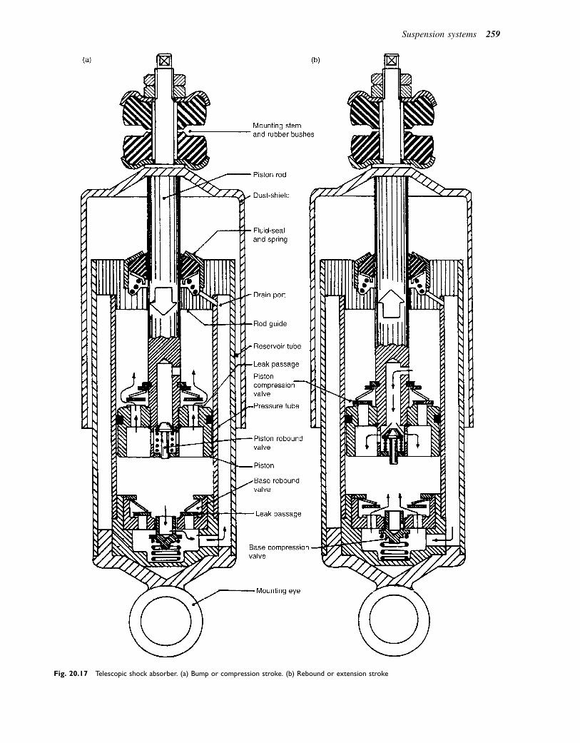
Fig. 20.17 Telescopic shock absorber. (a) Bump or compression stroke. (b) Rebound or extension stroke
Suspension systems 259
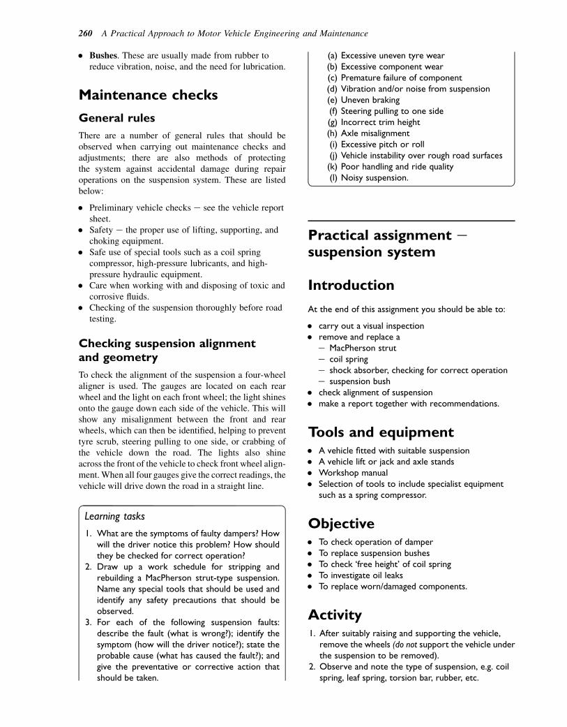
� Bushes. These are usually made from rubber toreduce vibration, noise, and the need for lubrication.
Maintenance checks
General rules
There are a number of general rules that should beobserved when carrying out maintenance checks andadjustments; there are also methods of protectingthe system against accidental damage during repairoperations on the suspension system. These are listedbelow:
� Preliminary vehicle checks e see the vehicle reportsheet.
� Safety e the proper use of lifting, supporting, andchoking equipment.
� Safe use of special tools such as a coil springcompressor, high-pressure lubricants, and high-pressure hydraulic equipment.
� Care when working with and disposing of toxic andcorrosive fluids.
� Checking of the suspension thoroughly before roadtesting.
Checking suspension alignmentand geometry
To check the alignment of the suspension a four-wheelaligner is used. The gauges are located on each rearwheel and the light on each front wheel; the light shinesonto the gauge down each side of the vehicle. This willshow any misalignment between the front and rearwheels, which can then be identified, helping to preventtyre scrub, steering pulling to one side, or crabbing ofthe vehicle down the road. The lights also shineacross the front of the vehicle to check front wheel align-ment. When all four gauges give the correct readings, thevehicle will drive down the road in a straight line.
Learning tasks
1. What are the symptoms of faulty dampers? Howwill the driver notice this problem? How shouldthey be checked for correct operation?
2. Draw up a work schedule for stripping andrebuilding a MacPherson strut-type suspension.Name any special tools that should be used andidentify any safety precautions that should beobserved.
3. For each of the following suspension faults:describe the fault (what is wrong?); identify thesymptom (how will the driver notice?); state theprobable cause (what has caused the fault?); andgive the preventative or corrective action thatshould be taken.
(a) Excessive uneven tyre wear(b) Excessive component wear(c) Premature failure of component(d) Vibration and/or noise from suspension(e) Uneven braking(f) Steering pulling to one side(g) Incorrect trim height(h) Axle misalignment(i) Excessive pitch or roll(j) Vehicle instability over rough road surfaces(k) Poor handling and ride quality(l) Noisy suspension.
Practical assignment esuspension system
Introduction
At the end of this assignment you should be able to:
� carry out a visual inspection� remove and replace a
e MacPherson strute coil springe shock absorber, checking for correct operatione suspension bush
� check alignment of suspension� make a report together with recommendations.
Tools and equipment� A vehicle fitted with suitable suspension� A vehicle lift or jack and axle stands� Workshop manual� Selection of tools to include specialist equipment
such as a spring compressor.
Objective� To check operation of damper� To replace suspension bushes� To check ‘free height’ of coil spring� To investigate oil leaks� To replace worn/damaged components.
Activity1. After suitably raising and supporting the vehicle,
remove the wheels (do not support the vehicle underthe suspension to be removed).
2. Observe and note the type of suspension, e.g. coilspring, leaf spring, torsion bar, rubber, etc.
260 A Practical Approach to Motor Vehicle Engineering and Maintenance
3. Make a simple sketch of the layout.4. Before cleaning around the mounting points look for
signs of:(a) insecure or loose components(b) places where dirt may be rubbed off by
something catching(c) bright or rusty streak marks where body or
chassis may be cracked(d) rust where thickness of material may be reduced
to a failure level(e) excessively worn components(f) accident damage to body or components.
5. Remove suspension and dismantle where necessary.6. Check operation of damper.7. Reassemble suspension (replacing any worn/broken
components) according to manufacturer’s manual.8. Check for correct assembly and tightness of all
mounting bolts before fitting wheel.9. Complete an inspection report and
recommendations for the customer.
Checklist
Vehicle
Removal and refitting
MacPherson strutCoil springLeaf springShock absorberRubber suspension bush
Dismantle and reassemble
MacPherson strutShock absorber
Checking and adjusting
Castor angleCamber angleKing pin inclinationToe-out on turnsWheel alignmentAxle alignmentBody alignmentRide height
Investigating and reporting
RubberHydrogasHydrolasticHydropneumaticCoil springLeaf springAir
Student’s signature
Supervisor’s signature
Self-assessment questions1. The rear suspension system shown in
Fig. 20.13:(a) is a trailing arm type(b) is a torque tube transaxle type(c) has no unsprung weight(d) is a dead axle.
2. A principal task of the suspension dampers:(a) is to dampen out spring vibrations(b) is to allow the use of weaker springs(c) is to keep the vehicle upright on corners(d) is to eliminate axle tramp under braking.
3. Coil spring suspension systems:(a) are lighter than leaf spring suspension
systems(b) require the use of radius arms to transmit driving
and braking forces from the wheels to the vehicleframe
(c) do not require the use of suspensiondampers
(d) are only suitable for small vehicles.4. With independent front suspension:
(a) the engine can be set lower in the frame becausethere is no axle beam
(b) vertical movement of a wheel on one side of thevehicle will cause the wheel on the opposite sideto move in a similar way
(c) double-acting dampers are essential(d) tyre wear is lower than it is on beam axle
systems.5. In leaf spring-type suspension systems:
(a) extra tie rods are needed in order to transmitdriving and braking forces from the wheels to thevehicle body
(b) both ends of the spring are rigidly fixed to thechassis
(c) driving and braking forces are transmitted to thechassis through the spring leaves
(d) extra strong dampers are required to cope withthe greater tendency for this type of suspensionto vibrate.
6. Figure 20.7 shows a Panhard rod fitted to a coil springsuspension. The purpose of this rod is to:(a) limit vertical movement of the vehicle body
relative to the road wheels(b) transmit cornering forces between the vehicle
body and the axle(c) absorb braking torque reaction(d) secure the brake caliper to the vehicle frame.
Suspension systems 261

7. In a hydropneumatic suspension unit:(a) ride height is fixed at a constant level(b) ride height is varied by introducing or removing
hydraulic fluid from the chamber below the gasdiaphragm
(c) gas is pumped in and out of the chamber abovethe gas diaphragm
(d) the equivalent spring rate is constant.
8. An active suspension system:(a) uses an ECU to adjust suspension characteristics
to suit driving conditions(b) is only suitable for use on racing cars(c) has fewer working parts than a non-active-type
suspension system(d) can only work on torsion bar-type suspension.
262 A Practical Approach to Motor Vehicle Engineering and Maintenance
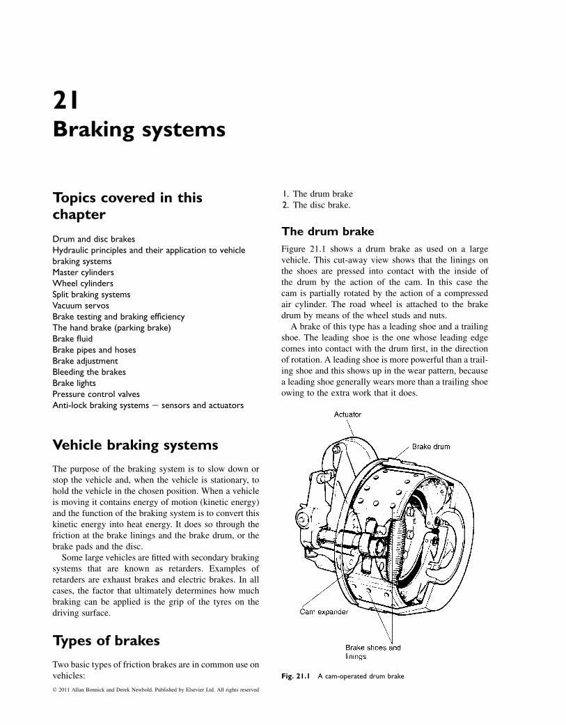
21Braking systems
Topics covered in thischapter
Drum and disc brakesHydraulic principles and their application to vehiclebraking systemsMaster cylindersWheel cylindersSplit braking systemsVacuum servosBrake testing and braking efficiencyThe hand brake (parking brake)Brake fluidBrake pipes and hosesBrake adjustmentBleeding the brakesBrake lightsPressure control valvesAnti-lock braking systems e sensors and actuators
Vehicle braking systems
The purpose of the braking system is to slow down orstop the vehicle and, when the vehicle is stationary, tohold the vehicle in the chosen position. When a vehicleis moving it contains energy of motion (kinetic energy)and the function of the braking system is to convert thiskinetic energy into heat energy. It does so through thefriction at the brake linings and the brake drum, or thebrake pads and the disc.
Some large vehicles are fitted with secondary brakingsystems that are known as retarders. Examples ofretarders are exhaust brakes and electric brakes. In allcases, the factor that ultimately determines how muchbraking can be applied is the grip of the tyres on thedriving surface.
Types of brakes
Two basic types of friction brakes are in common use onvehicles:
1. The drum brake2. The disc brake.
The drum brake
Figure 21.1 shows a drum brake as used on a largevehicle. This cut-away view shows that the linings onthe shoes are pressed into contact with the inside ofthe drum by the action of the cam. In this case thecam is partially rotated by the action of a compressedair cylinder. The road wheel is attached to the brakedrum by means of the wheel studs and nuts.
A brake of this type has a leading shoe and a trailingshoe. The leading shoe is the one whose leading edgecomes into contact with the drum first, in the directionof rotation. A leading shoe is more powerful than a trail-ing shoe and this shows up in the wear pattern, becausea leading shoe generally wears more than a trailing shoeowing to the extra work that it does.
Fig. 21.1 A cam-operated drum brake
� 2011 Allan Bonnick and Derek Newbold. Published by Elsevier Ltd. All rights reserved
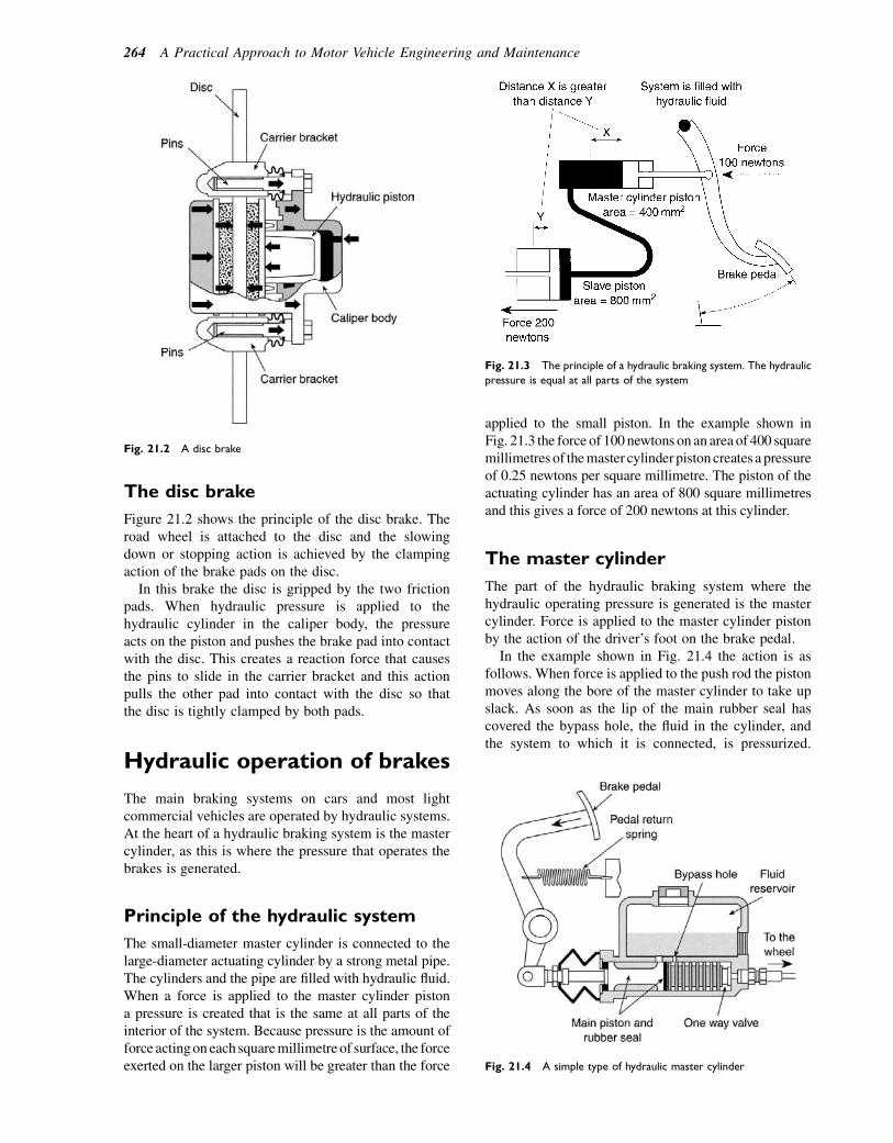
The disc brake
Figure 21.2 shows the principle of the disc brake. Theroad wheel is attached to the disc and the slowingdown or stopping action is achieved by the clampingaction of the brake pads on the disc.
In this brake the disc is gripped by the two frictionpads. When hydraulic pressure is applied to thehydraulic cylinder in the caliper body, the pressureacts on the piston and pushes the brake pad into contactwith the disc. This creates a reaction force that causesthe pins to slide in the carrier bracket and this actionpulls the other pad into contact with the disc so thatthe disc is tightly clamped by both pads.
Hydraulic operation of brakes
The main braking systems on cars and most lightcommercial vehicles are operated by hydraulic systems.At the heart of a hydraulic braking system is the mastercylinder, as this is where the pressure that operates thebrakes is generated.
Principle of the hydraulic system
The small-diameter master cylinder is connected to thelarge-diameter actuating cylinder by a strong metal pipe.The cylinders and the pipe are filled with hydraulic fluid.When a force is applied to the master cylinder pistona pressure is created that is the same at all parts of theinterior of the system. Because pressure is the amount offorce actingoneach squaremillimetre of surface, the forceexerted on the larger piston will be greater than the force
applied to the small piston. In the example shown inFig. 21.3 the force of 100 newtons on an area of 400 squaremillimetres of themaster cylinder pistoncreates a pressureof 0.25 newtons per square millimetre. The piston of theactuating cylinder has an area of 800 square millimetresand this gives a force of 200 newtons at this cylinder.
The master cylinder
The part of the hydraulic braking system where thehydraulic operating pressure is generated is the mastercylinder. Force is applied to the master cylinder pistonby the action of the driver’s foot on the brake pedal.
In the example shown in Fig. 21.4 the action is asfollows. When force is applied to the push rod the pistonmoves along the bore of the master cylinder to take upslack. As soon as the lip of the main rubber seal hascovered the bypass hole, the fluid in the cylinder, andthe system to which it is connected, is pressurized.
Fig. 21.2 A disc brake
Fig. 21.3 The principle of a hydraulic braking system. The hydraulic
pressure is equal at all parts of the system
Fig. 21.4 A simple type of hydraulic master cylinder
264 A Practical Approach to Motor Vehicle Engineering and Maintenance

When the force on the brake pedal and the mastercylinder push rod is released, the return spring pushesthe piston back and the hydraulic operating pressure isremoved. The action of the main piston seal ensuresthat the master cylinder remains filled with fluid.
Wheel cylinders
The hydraulic cylinders that push the drum brake shoesapart, or apply the clamping force in the disc brake, arethe wheel cylinders. There are two principal types ofwheel cylinders, a single-acting cylinder and a double-acting cylinder.
The single-acting wheel cylinder
In the single acting wheel cylinder shown in Fig. 21.5,the space in the wheel cylinder, behind the piston andseal, is filled with brake fluid. Pressure from the mastercylinder is applied to the wheel cylinders through pipes.Increased fluid pressure pushes the piston out and thisforce is applied to the brake shoe or brake pad.
Double-acting wheel cylinder
Figure 21.6 shows that the double-acting wheel cylinderhas two pistons and rubber seals. Hydraulic pressureapplied between the pistons pushes them apart. Thepistons then act on the brake shoes and moves thelinings into contact with the inside of the brake drum.
The handbrake
The handbrake (parking brake) is required to hold thevehicle in any chosen position when the vehicle isstationary. In addition to its function as a parkingbrake, the handbrake is also used when making hillstarts and similar manoeuvres. The handbrake alsoserves as an emergency brake in the event of failureof the main braking system. Figure 21.7 shows thelayout and main features of a handbrake for a car orlight van. The vehicle has trailing arm rear suspensionand the four swivel sector pivots are needed to guidethe cable on these suspension arms. The purpose ofthe compensator is to ensure that equal braking forceis applied to each side of the vehicle. The handbrake
normally operates through the brakes at the rear ofthe vehicle.
With normal use, the brake linings will wear and it isalso possible that the handbrake cable may stretcha little. In order to keep the handbrake working prop-erly it is provided with an adjustment, as shown inFig. 21.8.
The nut (2) is the adjusting nut and the nut (1) is thelock nut. In order to adjust the handbrake, the rear ofthe vehicle must be lifted so that the wheels are clearof the ground. The normal safety precautions must beobserved and the wheels should be checked for freedomof rotation after the cable has been adjusted.
Split braking systems
The split braking circuit provides for emergencies suchas a leak in one area of the braking system. There are
Fig. 21.5 A single-acting hydraulic wheel cylinder
Fig. 21.6 A double-acting hydraulic wheel cylinder. (a) Rover 200
series drum brake. (b) A double-acting wheel cylinder
Braking systems 265
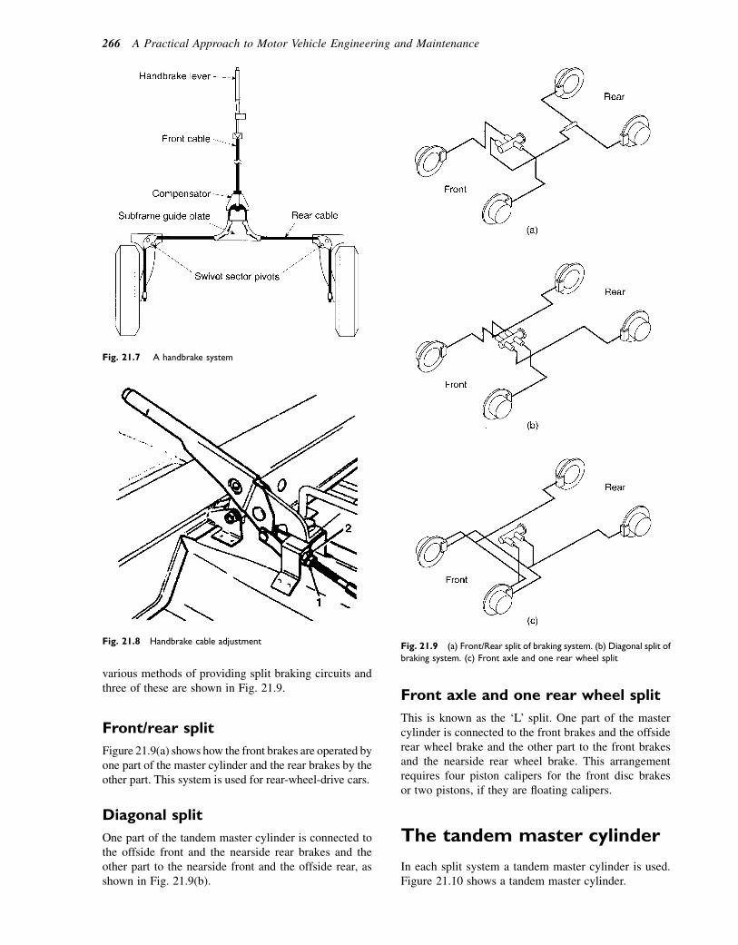
various methods of providing split braking circuits andthree of these are shown in Fig. 21.9.
Front/rear split
Figure 21.9(a) shows how the front brakes are operated byone part of the master cylinder and the rear brakes by theother part. This system is used for rear-wheel-drive cars.
Diagonal split
One part of the tandem master cylinder is connected tothe offside front and the nearside rear brakes and theother part to the nearside front and the offside rear, asshown in Fig. 21.9(b).
Front axle and one rear wheel split
This is known as the ‘L’ split. One part of the mastercylinder is connected to the front brakes and the offsiderear wheel brake and the other part to the front brakesand the nearside rear wheel brake. This arrangementrequires four piston calipers for the front disc brakesor two pistons, if they are floating calipers.
The tandem master cylinder
In each split system a tandem master cylinder is used.Figure 21.10 shows a tandem master cylinder.
Fig. 21.7 A handbrake system
Fig. 21.8 Handbrake cable adjustmentFig. 21.9 (a) Front/Rear split of braking system. (b) Diagonal split of
braking system. (c) Front axle and one rear wheel split
266 A Practical Approach to Motor Vehicle Engineering and Maintenance

The master cylinder is designed to ensure that thebrakes are applied evenly. There are two pistons,a primary piston and a secondary piston. The spring(1) is part of the primary piston and it is stronger thanthe spring (2) that is fitted to the secondary piston.Application of force to the piston causes the spring (1)to apply force to the secondary piston so that bothpistons move along the cylinder together. The twopiston recuperation seals cover their respective cut-offports at the same time and this ensures simultaneousbuild-up of pressure in the primary and secondarycircuits.
When the brake pedal force is released, the primaryand secondary pistons are pushed back by the secondaryspring and both cut-off ports are opened at the sametime, thus releasing the brakes simultaneously.
In the event of leakage from one part of the mastercylinder, the other cylinder remains operative. This isachieved through the design of the stops and otherfeatures of the master cylinder.
The brake fluid reservoir
The fluid reservoir is usually mounted directly on to themaster cylinder. Figure 21.11 shows a fluid reservoirequipped with a fluid level indicator. The fluid reservoiris normally made from translucent plastic and, providedit is kept clean, it is possible to view the fluid level byunder-bonnet inspection. The reservoir is fitted withan internal dividing panel, ensuring that one sectionremains operative should the other section develop
a loss of fluid. The fluid level indicator operatesa warning light. Should the fluid level drop below therequired level, the switch contacts will close and thewarning light on the dash panel will be illuminated.
Brake pipes and hoses
The hydraulic pressure created at the master cylinder isconveyed to the wheel brakes through strong metalpipes, where they can be clipped firmly to the vehicle,and through flexible hoses where there is relative move-ment between the parts, for example axles and steeredwheels and the vehicle frame.
The brake servo
A brake servo of the type shown in Fig. 21.12 is used asa means of increasing the force that the driver applies tothe brake pedal. The servo is the device that allows thedriver to apply a large braking force by the applicationof relatively light force from the foot. The amount ofincreased force that is produced by the servo is depen-dent on the driver’s effort that is applied to the brakepedal. This ensures that braking effort is proportionalto the force applied to the brake pedal.
Fig. 21.10 A tandem master cylinder
Fig. 21.11 The fluid level indicator
Braking systems 267
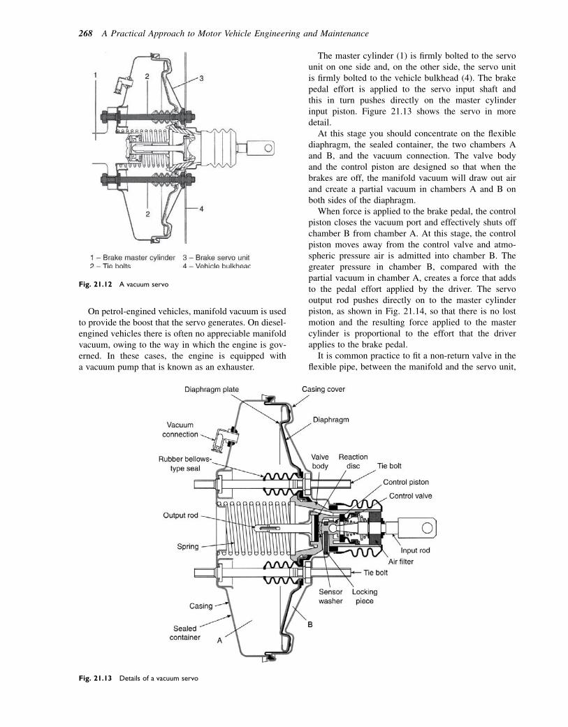
On petrol-engined vehicles, manifold vacuum is usedto provide the boost that the servo generates. On diesel-engined vehicles there is often no appreciable manifoldvacuum, owing to the way in which the engine is gov-erned. In these cases, the engine is equipped witha vacuum pump that is known as an exhauster.
The master cylinder (1) is firmly bolted to the servounit on one side and, on the other side, the servo unitis firmly bolted to the vehicle bulkhead (4). The brakepedal effort is applied to the servo input shaft andthis in turn pushes directly on the master cylinderinput piston. Figure 21.13 shows the servo in moredetail.
At this stage you should concentrate on the flexiblediaphragm, the sealed container, the two chambers Aand B, and the vacuum connection. The valve bodyand the control piston are designed so that when thebrakes are off, the manifold vacuum will draw out airand create a partial vacuum in chambers A and B onboth sides of the diaphragm.
When force is applied to the brake pedal, the controlpiston closes the vacuum port and effectively shuts offchamber B from chamber A. At this stage, the controlpiston moves away from the control valve and atmo-spheric pressure air is admitted into chamber B. Thegreater pressure in chamber B, compared with thepartial vacuum in chamber A, creates a force that addsto the pedal effort applied by the driver. The servooutput rod pushes directly on to the master cylinderpiston, as shown in Fig. 21.14, so that there is no lostmotion and the resulting force applied to the mastercylinder is proportional to the effort that the driverapplies to the brake pedal.
It is common practice to fit a non-return valve in theflexible pipe, between the manifold and the servo unit,
Fig. 21.13 Details of a vacuum servo
Fig. 21.12 A vacuum servo
268 A Practical Approach to Motor Vehicle Engineering and Maintenance
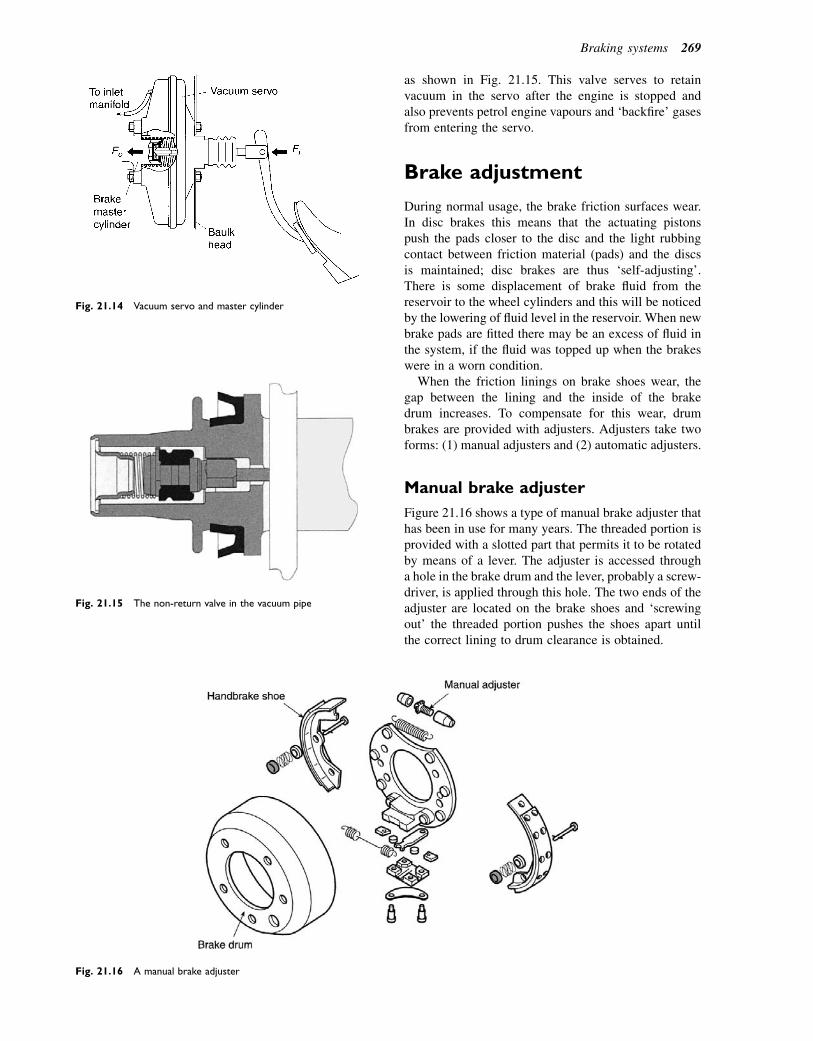
as shown in Fig. 21.15. This valve serves to retainvacuum in the servo after the engine is stopped andalso prevents petrol engine vapours and ‘backfire’ gasesfrom entering the servo.
Brake adjustment
During normal usage, the brake friction surfaces wear.In disc brakes this means that the actuating pistonspush the pads closer to the disc and the light rubbingcontact between friction material (pads) and the discsis maintained; disc brakes are thus ‘self-adjusting’.There is some displacement of brake fluid from thereservoir to the wheel cylinders and this will be noticedby the lowering of fluid level in the reservoir. When newbrake pads are fitted there may be an excess of fluid inthe system, if the fluid was topped up when the brakeswere in a worn condition.
When the friction linings on brake shoes wear, thegap between the lining and the inside of the brakedrum increases. To compensate for this wear, drumbrakes are provided with adjusters. Adjusters take twoforms: (1) manual adjusters and (2) automatic adjusters.
Manual brake adjuster
Figure 21.16 shows a type of manual brake adjuster thathas been in use for many years. The threaded portion isprovided with a slotted part that permits it to be rotatedby means of a lever. The adjuster is accessed througha hole in the brake drum and the lever, probably a screw-driver, is applied through this hole. The two ends of theadjuster are located on the brake shoes and ‘screwingout’ the threaded portion pushes the shoes apart untilthe correct lining to drum clearance is obtained.
Fig. 21.14 Vacuum servo and master cylinder
Fig. 21.15 The non-return valve in the vacuum pipe
Fig. 21.16 A manual brake adjuster
Braking systems 269
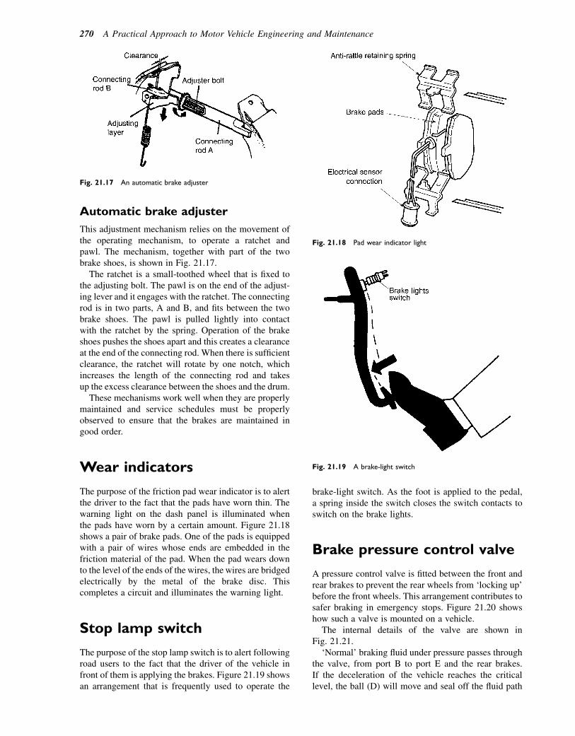
Automatic brake adjuster
This adjustment mechanism relies on the movement ofthe operating mechanism, to operate a ratchet andpawl. The mechanism, together with part of the twobrake shoes, is shown in Fig. 21.17.
The ratchet is a small-toothed wheel that is fixed tothe adjusting bolt. The pawl is on the end of the adjust-ing lever and it engages with the ratchet. The connectingrod is in two parts, A and B, and fits between the twobrake shoes. The pawl is pulled lightly into contactwith the ratchet by the spring. Operation of the brakeshoes pushes the shoes apart and this creates a clearanceat the end of the connecting rod. When there is sufficientclearance, the ratchet will rotate by one notch, whichincreases the length of the connecting rod and takesup the excess clearance between the shoes and the drum.
These mechanisms work well when they are properlymaintained and service schedules must be properlyobserved to ensure that the brakes are maintained ingood order.
Wear indicators
The purpose of the friction pad wear indicator is to alertthe driver to the fact that the pads have worn thin. Thewarning light on the dash panel is illuminated whenthe pads have worn by a certain amount. Figure 21.18shows a pair of brake pads. One of the pads is equippedwith a pair of wires whose ends are embedded in thefriction material of the pad. When the pad wears downto the level of the ends of the wires, the wires are bridgedelectrically by the metal of the brake disc. Thiscompletes a circuit and illuminates the warning light.
Stop lamp switch
The purpose of the stop lamp switch is to alert followingroad users to the fact that the driver of the vehicle infront of them is applying the brakes. Figure 21.19 showsan arrangement that is frequently used to operate the
brake-light switch. As the foot is applied to the pedal,a spring inside the switch closes the switch contacts toswitch on the brake lights.
Brake pressure control valve
A pressure control valve is fitted between the front andrear brakes to prevent the rear wheels from ‘locking up’before the front wheels. This arrangement contributes tosafer braking in emergency stops. Figure 21.20 showshow such a valve is mounted on a vehicle.
The internal details of the valve are shown inFig. 21.21.
‘Normal’ braking fluid under pressure passes throughthe valve, from port B to port E and the rear brakes.If the deceleration of the vehicle reaches the criticallevel, the ball (D) will move and seal off the fluid path
Fig. 21.17 An automatic brake adjuster
Fig. 21.18 Pad wear indicator light
Fig. 21.19 A brake-light switch
270 A Practical Approach to Motor Vehicle Engineering and Maintenance

to the bore of the valve (F). At this point the rear brakesare effectively ‘cut off’ from the front brakes and thepressure on the rear brakes is held at its original level.Further pressure on the brake pedal increases the frontbrake pressure without increasing the rear brake pres-sure. Dependent on the design of the valve, further brakepedal pressure will cause the piston (GeH) to move andincrease the pressure in the rear brake line.
When the deceleration falls, the ball will ‘roll’ back toits seat on the diffuser (C) and the pressure throughoutthe braking system is stabilized.
Brake fluid
Brake fluid must have a boiling temperature of not lessthan 1908C, and a freezing temperature not higherthan 2408C. Brake fluid is hygroscopic, which meansthat it absorbs water from the atmosphere. Water inbrake fluid affects its boiling and freezing temperatures,
which is one of the reasons why brake fluid needs to bechanged at the recommended intervals.
Brake fluid is normally based on vegetable oil and itscomposition is carefully controlled to ensure that it iscompatible with the rubber seals and not corrosive tothe metal parts. Some manufacturers use mineral oilas a base for brake fluids and their systems are designedto work with this fluid. It is important always to use onlythe type of fluid that a vehicle manufacturer recom-mends for use in their vehicles.
Braking efficiency
The concept of braking efficiency is based on the ‘idea’that the maximum retardation (rate of slowing down)that can be obtained from a vehicle braking system isgravitational acceleration, g5 9.8 m/s2. The actual retar-dation obtained from a vehicle is expressed asa percentage of ‘g’ and this is the braking efficiency.For example, suppose that a vehicle braking systemproduces a retardation of 7 m/s2. The braking efficiency5 (7/9.8)3 1005 71%.Becauseof thephysics of vehicledynamics the braking efficiency can be obtained withoutactually measuring deceleration. This is so because thetotal weight of the vehicle divided by the sum of thebraking forces applied between the tyres and the drivingsurface produces the same result. The roller brake testersof the type shown in Fig. 21.22 that are used in garagesmake use of this principle to measure braking efficiency.
The left (F1) and right (F2) front braking forces aremeasured and recorded. The vehicle is moved forwardso that the rear wheels are on the rollers. The test proce-dure is repeated and the two rear wheel braking forces(F3 and F4) are recorded. The four forces are addedtogether and divided by the weight of the vehicle.
For example, in a certain brake test on a vehicleweighing 1700 kg, the four braking forces add up to1070 kg. This gives a braking efficiency of (1070/1700)3 1005 63%. Often the data relating to a partic-ular vehicle is contained on a chart kept near the test bay.
The regulations regarding braking efficiency and thepermitted differences in braking, from side to side ofthe vehicle, together with other data are contained in thetester’s manual. Any technician carrying out brake testsmust familiarize themselves with the current regulations.
Fig. 21.20 The pressure-limiting valve on the vehicle
Fig. 21.21 Internal detail (cross-sectional view) of inertia-type
limiting brake pressure control valve e diagram simplified to show
schematic flow of fluid
Fig. 21.22 Roller-type brake tester measuring the braking force at
each wheel
Braking systems 271
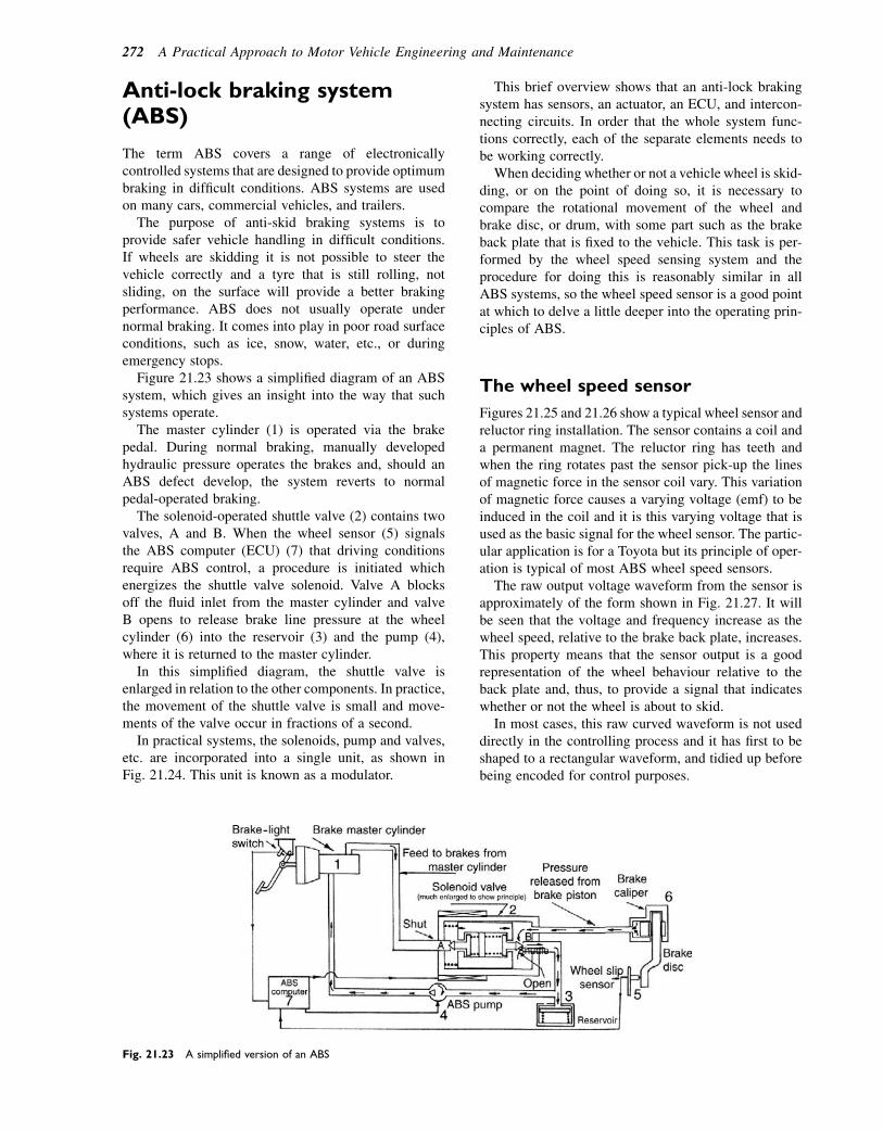
Anti-lock braking system(ABS)
The term ABS covers a range of electronicallycontrolled systems that are designed to provide optimumbraking in difficult conditions. ABS systems are usedon many cars, commercial vehicles, and trailers.
The purpose of anti-skid braking systems is toprovide safer vehicle handling in difficult conditions.If wheels are skidding it is not possible to steer thevehicle correctly and a tyre that is still rolling, notsliding, on the surface will provide a better brakingperformance. ABS does not usually operate undernormal braking. It comes into play in poor road surfaceconditions, such as ice, snow, water, etc., or duringemergency stops.
Figure 21.23 shows a simplified diagram of an ABSsystem, which gives an insight into the way that suchsystems operate.
The master cylinder (1) is operated via the brakepedal. During normal braking, manually developedhydraulic pressure operates the brakes and, should anABS defect develop, the system reverts to normalpedal-operated braking.
The solenoid-operated shuttle valve (2) contains twovalves, A and B. When the wheel sensor (5) signalsthe ABS computer (ECU) (7) that driving conditionsrequire ABS control, a procedure is initiated whichenergizes the shuttle valve solenoid. Valve A blocksoff the fluid inlet from the master cylinder and valveB opens to release brake line pressure at the wheelcylinder (6) into the reservoir (3) and the pump (4),where it is returned to the master cylinder.
In this simplified diagram, the shuttle valve isenlarged in relation to the other components. In practice,the movement of the shuttle valve is small and move-ments of the valve occur in fractions of a second.
In practical systems, the solenoids, pump and valves,etc. are incorporated into a single unit, as shown inFig. 21.24. This unit is known as a modulator.
This brief overview shows that an anti-lock brakingsystem has sensors, an actuator, an ECU, and intercon-necting circuits. In order that the whole system func-tions correctly, each of the separate elements needs tobe working correctly.
When deciding whether or not a vehicle wheel is skid-ding, or on the point of doing so, it is necessary tocompare the rotational movement of the wheel andbrake disc, or drum, with some part such as the brakeback plate that is fixed to the vehicle. This task is per-formed by the wheel speed sensing system and theprocedure for doing this is reasonably similar in allABS systems, so the wheel speed sensor is a good pointat which to delve a little deeper into the operating prin-ciples of ABS.
The wheel speed sensor
Figures 21.25 and 21.26 show a typical wheel sensor andreluctor ring installation. The sensor contains a coil anda permanent magnet. The reluctor ring has teeth andwhen the ring rotates past the sensor pick-up the linesof magnetic force in the sensor coil vary. This variationof magnetic force causes a varying voltage (emf) to beinduced in the coil and it is this varying voltage that isused as the basic signal for the wheel sensor. The partic-ular application is for a Toyota but its principle of oper-ation is typical of most ABS wheel speed sensors.
The raw output voltage waveform from the sensor isapproximately of the form shown in Fig. 21.27. It willbe seen that the voltage and frequency increase as thewheel speed, relative to the brake back plate, increases.This property means that the sensor output is a goodrepresentation of the wheel behaviour relative to theback plate and, thus, to provide a signal that indicateswhether or not the wheel is about to skid.
In most cases, this raw curved waveform is not useddirectly in the controlling process and it has first to beshaped to a rectangular waveform, and tidied up beforebeing encoded for control purposes.
Fig. 21.23 A simplified version of an ABS
272 A Practical Approach to Motor Vehicle Engineering and Maintenance

If the brake is applied and the reluctor (rotor) starts todecelerate rapidly, relative to the sensor pick-up, it is anindication that the wheel rotation is slowing down. If theroad surface is dry and the tyre is gripping well, theretardation of the wheel will match that of the vehicleand normal braking will occur. However, if the roadsurface is slippery, a sudden braking application willcause the reluctor rotor and road wheel to decelerateat a greater rate than the vehicle, indicating that a skidis about to happen. This condition is interpreted by the
Fig. 21.24 ABS modulator
Fig. 21.25 ABS wheel sensor
Fig. 21.26 The basic principle of the ABS sensor
Fig. 21.27 The voltage waveform of the ABS sensor output
Braking systems 273
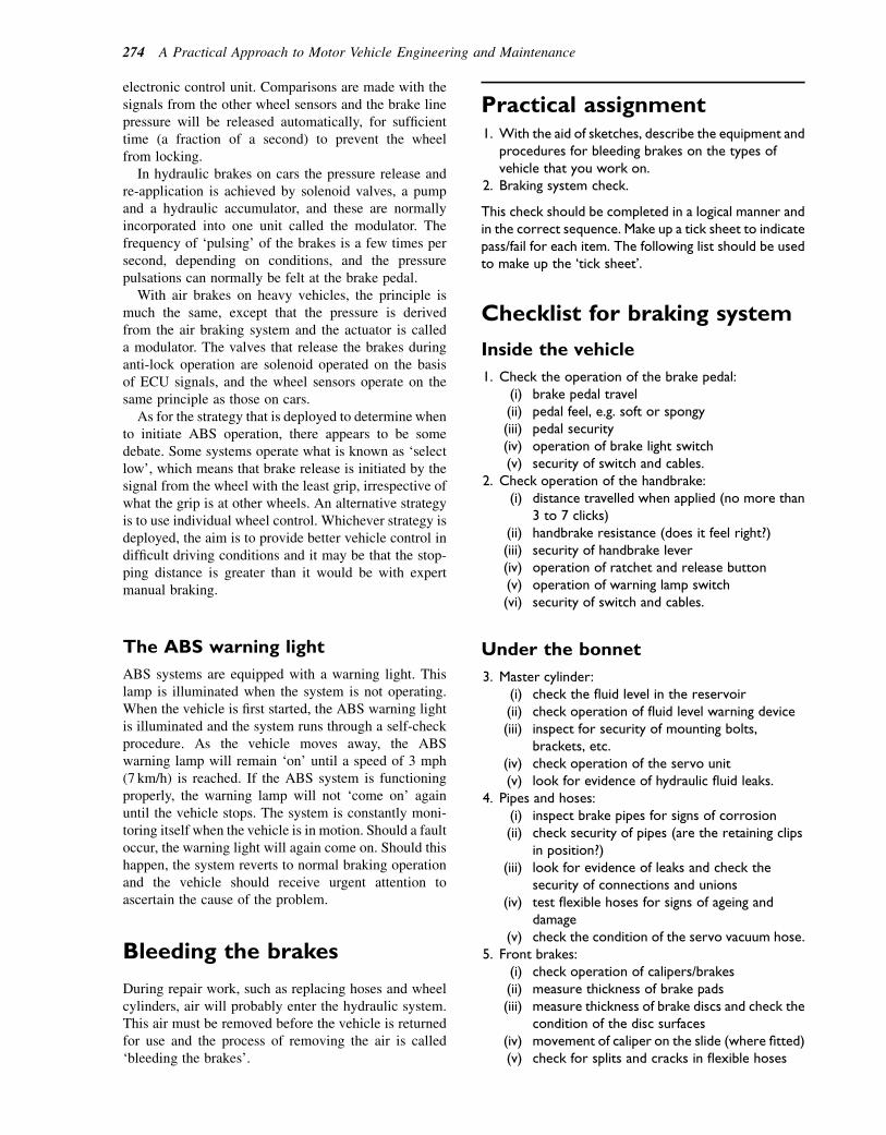
electronic control unit. Comparisons are made with thesignals from the other wheel sensors and the brake linepressure will be released automatically, for sufficienttime (a fraction of a second) to prevent the wheelfrom locking.
In hydraulic brakes on cars the pressure release andre-application is achieved by solenoid valves, a pumpand a hydraulic accumulator, and these are normallyincorporated into one unit called the modulator. Thefrequency of ‘pulsing’ of the brakes is a few times persecond, depending on conditions, and the pressurepulsations can normally be felt at the brake pedal.
With air brakes on heavy vehicles, the principle ismuch the same, except that the pressure is derivedfrom the air braking system and the actuator is calleda modulator. The valves that release the brakes duringanti-lock operation are solenoid operated on the basisof ECU signals, and the wheel sensors operate on thesame principle as those on cars.
As for the strategy that is deployed to determine whento initiate ABS operation, there appears to be somedebate. Some systems operate what is known as ‘selectlow’, which means that brake release is initiated by thesignal from the wheel with the least grip, irrespective ofwhat the grip is at other wheels. An alternative strategyis to use individual wheel control. Whichever strategy isdeployed, the aim is to provide better vehicle control indifficult driving conditions and it may be that the stop-ping distance is greater than it would be with expertmanual braking.
The ABS warning light
ABS systems are equipped with a warning light. Thislamp is illuminated when the system is not operating.When the vehicle is first started, the ABS warning lightis illuminated and the system runs through a self-checkprocedure. As the vehicle moves away, the ABSwarning lamp will remain ‘on’ until a speed of 3 mph(7 km/h) is reached. If the ABS system is functioningproperly, the warning lamp will not ‘come on’ againuntil the vehicle stops. The system is constantly moni-toring itself when the vehicle is in motion. Should a faultoccur, the warning light will again come on. Should thishappen, the system reverts to normal braking operationand the vehicle should receive urgent attention toascertain the cause of the problem.
Bleeding the brakes
During repair work, such as replacing hoses and wheelcylinders, air will probably enter the hydraulic system.This air must be removed before the vehicle is returnedfor use and the process of removing the air is called‘bleeding the brakes’.
Practical assignment1. With the aid of sketches, describe the equipment and
procedures for bleeding brakes on the types ofvehicle that you work on.
2. Braking system check.
This check should be completed in a logical manner andin the correct sequence. Make up a tick sheet to indicatepass/fail for each item. The following list should be usedto make up the ‘tick sheet’.
Checklist for braking system
Inside the vehicle
1. Check the operation of the brake pedal:(i) brake pedal travel(ii) pedal feel, e.g. soft or spongy(iii) pedal security(iv) operation of brake light switch(v) security of switch and cables.
2. Check operation of the handbrake:(i) distance travelled when applied (no more than
3 to 7 clicks)(ii) handbrake resistance (does it feel right?)(iii) security of handbrake lever(iv) operation of ratchet and release button(v) operation of warning lamp switch(vi) security of switch and cables.
Under the bonnet
3. Master cylinder:(i) check the fluid level in the reservoir(ii) check operation of fluid level warning device(iii) inspect for security of mounting bolts,
brackets, etc.(iv) check operation of the servo unit(v) look for evidence of hydraulic fluid leaks.
4. Pipes and hoses:(i) inspect brake pipes for signs of corrosion(ii) check security of pipes (are the retaining clips
in position?)(iii) look for evidence of leaks and check the
security of connections and unions(iv) test flexible hoses for signs of ageing and
damage(v) check the condition of the servo vacuum hose.
5. Front brakes:(i) check operation of calipers/brakes(ii) measure thickness of brake pads(iii) measure thickness of brake discs and check the
condition of the disc surfaces(iv) movement of caliper on the slide (where fitted)(v) check for splits and cracks in flexible hoses
274 A Practical Approach to Motor Vehicle Engineering and Maintenance

(vi) check for corrosion and damage in metal pipesand check the unions for security and tightness
(vii) check the security and operation of the padwear indicator light and cables
(viii) check security and condition of anti-rattledevices
(ix) check for evidence of leaks(x) check for movement and excessive free play in
wheel bearings.6. Rear brakes:
(i) check condition of brake drums and look forevidence of scoring (ensure that dust removalis done with a vacuum cleaner whilst wearinga mask)
(ii) measure thickness of brake shoe linings(iii) check operation of wheel cylinders (will
require an assistant)(iv) check to see that all parts are in place and that
brakes are correctly assembled(v) check for fluid leaks(vi) check security and condition of brake pipes and
unions.7. Under the car:
(i) security of pipes and flexible hoses, check thatall retaining clips are properly fitted
(ii) look for any evidence of fluid leaks(iii) check the operation of handbrake cables,
compensator, etc.(iv) lubrication of cables and clevis pins(v) security of handbrake linkages.
Self-assessment questions1. Brake fluid is said to be hygroscopic because:
(a) it is like water(b) it absorbs water(c) it is heavier than water(d) it freezes at a higher temperature than water.
2. Brake fluid absorbs water over a period of time. Inorder to prevent problems that may arise from this itis recommended that:(a) brakes are not allowed to overheat(b) brake shoes are changed at regular intervals(c) brake fluid is replaced at regular intervals(d) vehicles are kept under cover in bad weather.
3. A diagonal split braking system requires:(a) two master cylinders(b) a tandem master cylinder(c) two calipers on each front brake(d) disc brakes at the front and drum brakes at the
rear.4. In a test to determine braking efficiency a vehicle
weighing 1200 kg is placed on a brake testingmachine, the brake tester showing the followingreadings: front right 2120 N; front left 2080 N; rearright 1490 N; rear left 15I0N. The braking efficiencyis:(a) 60%(b) 17%(c) 25%(d) 75%.
5. On diesel-engined vehicles the vacuum for the brakeservo is provided by:(a) manifold vacuum(b) a compressor(c) a vacuum pump known as an exhauster(d) a venturi fitted in the engine air intake.
6. Anti-lock braking systems:(a) decrease stopping distance in all conditions(b) assist the driver to retain control during
emergency stops(c) are not used on heavy vehicles(d) are a form of regenerative braking system.
7. Disc brakes are said to be self-adjusting because:(a) they use a ratchet and pawl mechanism(b) the pads are kept in light rubbing contact with the
disc(c) the discs expand when heated(d) the brake servo compensates for wear.
Braking systems 275

22Steering, wheels, and tyres
Topics covered in thischapter
Ackermann principleLight vehicle steering layoutsSteering geometryCastorCamber kingpin inclinationCentre-point steeringSteering roll axisWheel alignmentSteering gearboxesRack and pinionBall-jointsFront-hub assembliesRoad wheel constructionTyresTyre details, tread wear indicatorsTyre regulationsWheel balanceTyre wear patterns as a guide to steering misalignment
The steering mechanism has two main purposes. It mustenable the driver to: easily maintain the straight-aheaddirection of the vehicle even when bumps are encoun-tered at high speeds; and to change the direction ofthe vehicle with the minimum amount of effort at thesteering wheel. One of the simplest layouts is thebeam axle arrangement (Fig. 22.1) as used on largecommercial vehicles. This is where the hub pivots orswivels on a kingpin (in the case of a car a top andbottom ball-joint) to give the steering action.
As can be seen the two stub axles are connectedtogether by two steering arms and a track rod withball-joints at each end. The steering gearbox convertsthe rotary movement of the steering wheel intoa straight-line movement of the steering linkage; it alsomakes it easier for the driver to steer by giving a gearreduction. The drop arm and drag link connect the steer-ing gearbox to the stub axle. The steering arms, track rod,and ball-joints connect the stub axles together and allowthe movement to be transferred from one side of thevehicle to the other, as well as providing for the move-ment of the linkage as the suspension operates.
Fig. 22.1 Layout for beam axle steering system
� 2011 Allan Bonnick and Derek Newbold. Published by Elsevier Ltd. All rights reserved

Light vehicle steering layouts
To providemeans of turning the front wheels of a vehicleleft or right would not be too difficult were it not alsonecessary to make provision for their movement upand down with the suspension. Most modern cars nowhave a fully independent front suspension. This createsserious problems when one wheel moves upwards ordownwards independent of the opposite wheel. Ifa single track rod were used the tracking would alterevery time the wheels moved, causing the vehicle towander from the straight-ahead position. This problemhas been overcome by the use of two or three part trackrods. As can be seen from Fig. 22.2 on a vehicle fittedwith a rack and pinion type steering the centre trackrod has been replaced by the rack.
Learning tasks
1. Inspect several different types of vehicles andmake a simple line diagram of the layout of thesteering system, identifying the following compo-nents: steering wheel and column, gearbox,linkage and ball-joints, stub axles and swivel joints.
2. Identify how the tracking is adjusted, check themanufacturer’s setting for the tracking, and statethe tolerance given (the difference between theupper and lower readings). What equipment isused to check the measurements and how shouldit be set up on the vehicle?
3. When undertaking an MOT the steering systemshould be checked. Look in the MOT tester’smanual and list the areas that are subject totesting. What in particular is the tester lookingfor? Your list should include the following areas:(a) Inside the vehicle:� security of steering column mountings� play in upper steering column bush� amountofrotarymovement insteeringwheel
before movement of the steered wheels� amount of lift in steering column� security of steering wheel to column� any undue noise or stiffness when operating
the steering from lock to lock.(b) Under the vehicle:� security of steering box to chassis� signs of rust in the chassis around steering
box mounting� excessive wear in steering column universal
joints (these may be fitted inside the vehicle)� excessive play in steering box� amount of play in inner and outer track rod
ends� splits or holes in rubber boots (steering
rack arrangement)� loss of oil from steering box� play in suspension mountings and pivots
that may affect the operation of the steering� signs of uneven tread pattern wear that may
indicate a fault in the steering mechanism.
Fig. 22.2 Steering layout for independent front suspen-
sion (IFS) system
Steering, wheels, and tyres 277

Steering geometry
The subject of steering geometry is a very complex onein its own right and because of this many manufacturersimport the knowledge and skills of specialists. However,the basic principles are relatively simple to understandand apply to most vehicles. The development of thesteering and suspension (to which it is very closelylinked) is based on past experience; much of the workhas been through an evolutionary process, learningfrom mistakes and modifying systems to suit varyingapplications. Many of the terms used are applied onlyto the steering and have no alternative; hopefully mostof these are explained in the text.
The geometry of steering may best be understood bylooking at Fig. 22.3. A swinging beam mounted ona turntable frame turns the wheels. This keeps all thewheels at right angles to the centre of the turn, whichreduces tyre wear especially when turning a corner.
Rudolph Ackermann took out a patent in 1818 inEngland that is now widely used and is known as the
Ackermann layout. The angles of the front wheelsabout the turning point depend upon the wheel base(W ) and the width of the track (T ). In 1878 Jeantaudshowed that the layout should conform to Fig. 22.4. Inthis arrangement the inner wheel (A) turns througha larger angle than the outer wheel (B) to give true roll-ing motion. The Ackermann layout does not fullyachieve these conditions in all wheel positions; nor-mally it is only accurate when the wheels are straightahead and in one position on each left and right turnwheel setting. This system gives as near true rollingmotion as possible together with simplicity.
Ackermann principle
The Ackermann layout is obtained by arranging for thestub axles to swivel on kingpins or ball-joints to give thesteering action of the wheels. The track rod ball-jointsare positioned on an imaginary line drawn betweenthe kingpins and the centre line of the vehicle. Whenthe track rod is positioned behind the swivel pins it ismade shorter and has the protection of the axle, butthe rod must be made stronger as it is in compressionwhen the vehicle is being driven. This is shown inFig. 22.5(a). When it is positioned in front of the swivelpins (Fig. 22.5(b)), it is made longer and can be out ofthe way of the engine, and is made thinner as it is intension when the vehicle is being driven.
Figure 22.6 shows the arrangements for an indepen-dent front suspension where the top and bottomball-joints are placed in a line that forms the kingpininclination and also allows for the movement of thesteered wheels both up and down over the irregularitiesof the road surface and as the driver turns the wheels tonegotiate corners.
Fig. 22.3 Swing beam steering
Fig. 22.4 Differing angles of front wheels about centre of turn
Fig. 22.5(a) Track rod behind swivel pins still conform to
Ackermann principle
278 A Practical Approach to Motor Vehicle Engineering and Maintenance
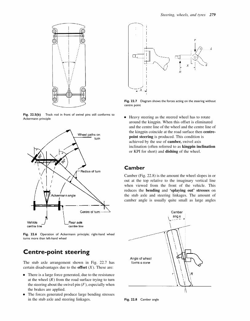
Centre-point steering
The stub axle arrangement shown in Fig. 22.7 hascertain disadvantages due to the offset (X ). These are:
� There is a large force generated, due to the resistanceat the wheel (R ) from the road surface trying to turnthe steering about the swivel pin (F ), especially whenthe brakes are applied.
� The forces generated produce large bending stressesin the stub axle and steering linkages.
� Heavy steering as the steered wheel has to rotatearound the kingpin. When this offset is eliminatedand the centre line of the wheel and the centre line ofthe kingpin coincide at the road surface then centre-point steering is produced. This condition isachieved by the use of camber, swivel axisinclination (often referred to as kingpin inclinationor KPI for short) and dishing of the wheel.
Camber
Camber (Fig. 22.8) is the amount the wheel slopes in orout at the top relative to the imaginary vertical linewhen viewed from the front of the vehicle. Thisreduces the bending and ‘splaying out’ stresses onthe stub axle and steering linkages. The amount ofcamber angle is usually quite small as large angles
Fig. 22.5(b) Track rod in front of swivel pins still conforms to
Ackermann principle
Fig. 22.6 Operation of Ackermann principle; right-hand wheel
turns more than left-hand wheel
Fig. 22.7 Diagram shows the forces acting on the steering without
centre point
Fig. 22.8 Camber angle
Steering, wheels, and tyres 279

will produce rapid tyre wear on the shoulder of the tyretread as the inside tread of the tyre (R) travels a greaterdistance than the outside tread (r), even when travellingin a straight line. A cambered wheel tends to roll in thedirection in which it is leaning, which has the effect ofproducing a side force. Two beneficial effects of thisare that it reduces any small sideways forces imposedon the wheel by ridges in the road surface, and that italso produces a small lateral pre-load in the steeringlinkage. The actual angle varies depending on thesuspension system used, but normally it is no morethan 28.
Kingpin or swivel axis inclination(KPI)
When the kingpin is tilted inwards at the top the resultingangle between the vertical line and the kingpin centreline is called the kingpin inclination (Fig. 22.9). Nor-mally this will be between 58 and 158 to produce positiveoffset and to accommodate the brake, wheel bearings,and drive shaft joint. When the kingpin is set outwardsat the bottom then negative offset is produced.As the wheel is steered through an angle it will pivot
around the kingpin. This will have the effect of liftingthe front of the vehicle, helping to give a self-centringaction to the steering.
Steering roll radius
If the steering wheel is turned, the front wheels movealong an arc around (a) in Fig. 22.10; this is wherethe extension of the kingpin centre line meets theground. The point (b) is where the tyre centre linemeets the ground; radius (aeb) is the steering rollradius.
Whether the steering roll radius is positive or negativedepends on the position of the KPI. It is positive if theextension of the KPI axis meets the ground on the insideof the tyre contact centre. It is negative if the extensionof the KPI meets the ground outside the tyre contactcentre. The advantage of having negative steeringroll radius is increased directional stability in the caseof uneven braking forces on the front wheels, or ifa tyre is suddenly deflated.
As can be seen in Fig. 22.11, if the brake force on theright-hand front wheel is greater, then the vehicle tendsto slide in an arc around that wheel, which means thatthe rear of the vehicle veers out to the left. In a vehiclewith negative steering roll radius, the force of the car inmotion will turn the wheel with the stronger brakingforce around the lower arm formed by the steering rollradius.
Fig. 22.9 Kingpin inclination (KPI), sometimes referred to as swivel
axis
Fig. 22.10 Steering roll radius. (a) No steering roll radius. (b) Positive roll radius. (c) Negative roll radius
280 A Practical Approach to Motor Vehicle Engineering and Maintenance
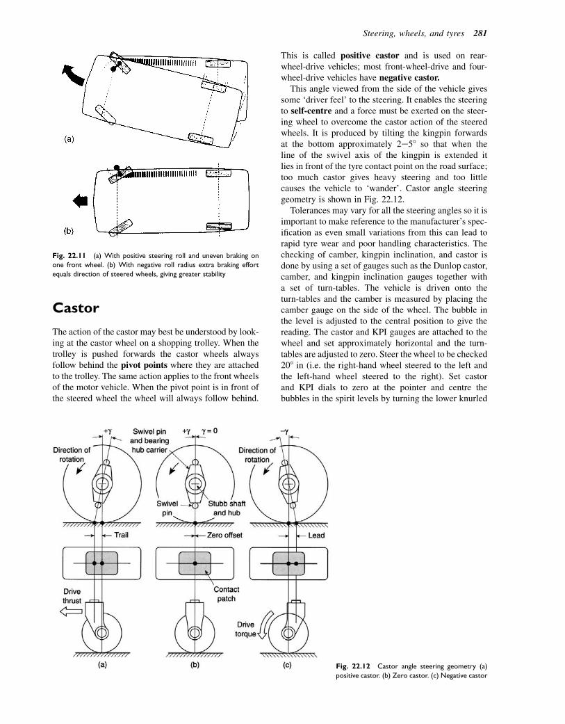
Castor
The action of the castor may best be understood by look-ing at the castor wheel on a shopping trolley. When thetrolley is pushed forwards the castor wheels alwaysfollow behind the pivot points where they are attachedto the trolley. The same action applies to the front wheelsof the motor vehicle. When the pivot point is in front ofthe steered wheel the wheel will always follow behind.
This is called positive castor and is used on rear-wheel-drive vehicles; most front-wheel-drive and four-wheel-drive vehicles have negative castor.
This angle viewed from the side of the vehicle givessome ‘driver feel’ to the steering. It enables the steeringto self-centre and a force must be exerted on the steer-ing wheel to overcome the castor action of the steeredwheels. It is produced by tilting the kingpin forwardsat the bottom approximately 2e58 so that when theline of the swivel axis of the kingpin is extended itlies in front of the tyre contact point on the road surface;too much castor gives heavy steering and too littlecauses the vehicle to ‘wander’. Castor angle steeringgeometry is shown in Fig. 22.12.
Tolerances may vary for all the steering angles so it isimportant to make reference to the manufacturer’s spec-ification as even small variations from this can lead torapid tyre wear and poor handling characteristics. Thechecking of camber, kingpin inclination, and castor isdone by using a set of gauges such as the Dunlop castor,camber, and kingpin inclination gauges together witha set of turn-tables. The vehicle is driven onto theturn-tables and the camber is measured by placing thecamber gauge on the side of the wheel. The bubble inthe level is adjusted to the central position to give thereading. The castor and KPI gauges are attached to thewheel and set approximately horizontal and the turn-tables are adjusted to zero. Steer the wheel to be checked208 in (i.e. the right-hand wheel steered to the left andthe left-hand wheel steered to the right). Set castorand KPI dials to zero at the pointer and centre thebubbles in the spirit levels by turning the lower knurled
Fig. 22.11 (a) With positive steering roll and uneven braking on
one front wheel. (b) With negative roll radius extra braking effort
equals direction of steered wheels, giving greater stability
Fig. 22.12 Castor angle steering geometry (a)
positive castor. (b) Zero castor. (c) Negative castor
Steering, wheels, and tyres 281
screws. Steer the wheel to be checked 208 out and centrethe bubbles in the spirit levels by turning the castor andKPI dials and take the readings off the dials.
Wheel alignment
Adjusting the track
Often referred to as toe-in/toe-out or tracking, wheelalignment is a plan view of the wheels and means ‘arethe wheels correctly aligned with each other?’ Whenthe vehicle is travelling in a straight line all the wheelsmust be parallel, especially the steered wheels.
Arrangement for changing or adjusting the track ismade in the track rod or outer track control arms and,when correctly aligned for toe-in, the distance acrossthe front of the steered wheels measures less than thedistance across the rear (Fig. 22.13(a)). These measure-ments are taken using very accurate measuring gauges,of which several types are available (e.g. the Dunlopoptical alignment gauge, Fig. 22.13(b)). The gaugesare set to zero and are positioned on the wheels. Thealignment is adjusted to give a reading on the scale, whichis then checked against the manufacturer’s specifications.
A more accurate method would be to use four wheelalignment gauges. This would give the mechanic moreprecise information as to which wheel needs adjusting,whether the front axle lines up with the rear axle andif the vehicle suspension has been misaligned in anaccident.
Toe-out on turns
When turning a corner, the inner wheel turns througha greater angle than the outer wheel. This differencein angles is called ‘toe-out on turns’ (Fig. 22.14(a)).To check these angles the wheels are placed on turnta-bles and the outer wheel is turned on its axis through208. The inner wheel should now read a larger angle(typically approximately 228). This is because it is roll-ing around a smaller radius.
When checking steering alignment such as toe-in ortoe-out, a number of factors must be attended to, forexample:
1. The vehicle must be on a level surface.2. The vehicle must be loaded to the maker’s
specification, such as may be the kerbside unladenweight figure.
3. The tyres must be inflated to the correct pressure.4. The front wheels should be in the straight-ahead
position.5. The vehicle should be rocked from side to side to
ease any stresses in the steering system.6. Prior to checking the track, the vehicle should
be rolled forward by about a vehicle’s length in orderto take up small amounts of slack in the linkage.
If the track requires adjustment (toe-in or toe-out) it isimportant to ensure that the track rods are maintained atthe correct lengths, because this will affect the toe-outon turns. In the example shown in Fig. 22.14(b), thetrack rods are of equal length. This may not alwaysapply and such details must be checked prior to makingany adjustments.
Learning tasks
1. Draw a simple diagram of the steering layout toconform to the Ackermann principle. Show theposition of the front and rear wheels, point ofturn, approximate angles of the front wheels,and the position of the track rod. Indicate onyour diagram where adjustments may be made.
2. Make a list of reasons why the steering mecha-nism would require adjusting.
3. Draw up a workshop schedule that you could usewhen checking a steering system for signs of wearand serviceability.
4. What important safety factors would youconsider when working under a vehicle on thesteering system.
5. Name two steering faults that would causeuneven tyre wear. How would these faults beput right?
6. If a customer came into the workshop complain-ing that his vehicle was ‘pulling to one side’ whenbeing driven in a straight line, what would yoususpect the fault to be? Describe the tests youwould undertake to confirm your diagnosis.
7. Check the tracking on a vehicle using both opticaland four-wheel alignment gauges. Adjust thesteering to the middle of the limits set by themanufacturer.
Steering gearboxes
The steering gearbox is incorporated into the steeringmechanism for two main reasons:
� to change the rotary movement of the steering wheelinto the straight-line movement of the drag link;
� to provide a gear reduction and therefore a torqueincrease, thus reducing the effort required by thedriver at the steering wheel.
Quite a number of different types of steering gear-boxes have been used over the years, the most commonones being:
� worm and roller� cam and peg� recirculating ball (half nut)� rack and pinion.
282 A Practical Approach to Motor Vehicle Engineering and Maintenance

Fig. 22.13 (a) Toe-in. (b) Dunlop AGO/40 optical alignment gauge
Steering, wheels, and tyres 283
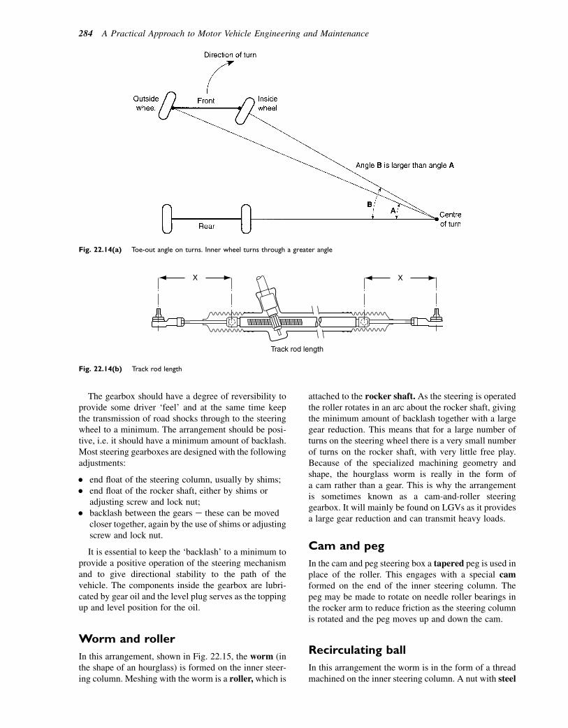
The gearbox should have a degree of reversibility toprovide some driver ‘feel’ and at the same time keepthe transmission of road shocks through to the steeringwheel to a minimum. The arrangement should be posi-tive, i.e. it should have a minimum amount of backlash.Most steering gearboxes are designed with the followingadjustments:
� end float of the steering column, usually by shims;� end float of the rocker shaft, either by shims or
adjusting screw and lock nut;� backlash between the gears e these can be moved
closer together, again by the use of shims or adjustingscrew and lock nut.
It is essential to keep the ‘backlash’ to a minimum toprovide a positive operation of the steering mechanismand to give directional stability to the path of thevehicle. The components inside the gearbox are lubri-cated by gear oil and the level plug serves as the toppingup and level position for the oil.
Worm and roller
In this arrangement, shown in Fig. 22.15, the worm (inthe shape of an hourglass) is formed on the inner steer-ing column. Meshing with the worm is a roller, which is
attached to the rocker shaft. As the steering is operatedthe roller rotates in an arc about the rocker shaft, givingthe minimum amount of backlash together with a largegear reduction. This means that for a large number ofturns on the steering wheel there is a very small numberof turns on the rocker shaft, with very little free play.Because of the specialized machining geometry andshape, the hourglass worm is really in the form ofa cam rather than a gear. This is why the arrangementis sometimes known as a cam-and-roller steeringgearbox. It will mainly be found on LGVs as it providesa large gear reduction and can transmit heavy loads.
Cam and peg
In the cam and peg steering box a tapered peg is used inplace of the roller. This engages with a special camformed on the end of the inner steering column. Thepeg may be made to rotate on needle roller bearings inthe rocker arm to reduce friction as the steering columnis rotated and the peg moves up and down the cam.
Recirculating ball
In this arrangement the worm is in the form of a threadmachined on the inner steering column. A nut with steel
Fig. 22.14(a) Toe-out angle on turns. Inner wheel turns through a greater angle
X X
Track rod length
Fig. 22.14(b) Track rod length
284 A Practical Approach to Motor Vehicle Engineering and Maintenance

ball bearings acting as the thread operates inside thenut; as the worm rotates the balls reduce the frictionto a minimum. In many cases a half nut is used anda transfer tube returns the balls back to the other sideof the nut. A peg on the nut locates in the rocker arm,which transfers a rocking motion to the rocker shaft.In Fig. 22.16 a sector gear is used to transfer themovement to the rocker shaft.
Rack and pinion
This type, shown in Fig. 22.17, is now probably the mostcommon type in use on cars and light vehicles. It hasa rack that takes the place of the middle track rod and
outer track rods (sometimes called tie rods), whichconnect to the steering arms at the hub. The pinion ismounted to the steering column by a universal joint asoften the steering column is not in line with the inputto the steering rack. This gives ease of mounting andoperation of the gearbox.
On each end of the rack is a ball-joint to which thetrack rod is mounted; these are spring loaded to allowfor movement together with the minimum of play inthe joint. The system is arranged so that in the eventof an accident the column, because it is out of align-ment (not a solid straight shaft), will tend to bend atthe joints. This helps to prevent the steering wheelfrom hitting the driver’s chest and causing serious
Fig. 22.15 Worm and roller steering
gearbox
Fig. 22.16 Recirculating ball rack and sector steering box
Steering, wheels, and tyres 285
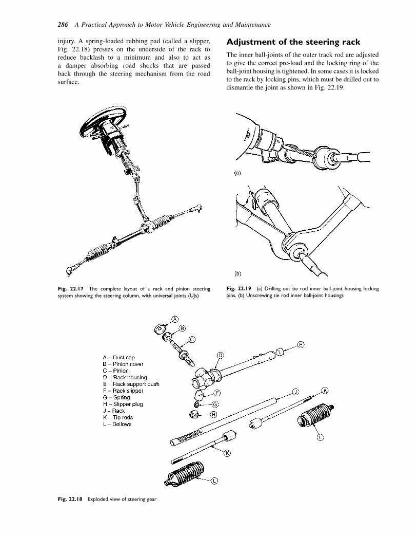
injury. A spring-loaded rubbing pad (called a slipper,Fig. 22.18) presses on the underside of the rack toreduce backlash to a minimum and also to act asa damper absorbing road shocks that are passedback through the steering mechanism from the roadsurface.
Adjustment of the steering rack
The inner ball-joints of the outer track rod are adjustedto give the correct pre-load and the locking ring of theball-joint housing is tightened. In some cases it is lockedto the rack by locking pins, which must be drilled out todismantle the joint as shown in Fig. 22.19.
Fig. 22.17 The complete layout of a rack and pinion steering
system showing the steering column, with universal joints (UJs)
Fig. 22.18 Exploded view of steering gear
Fig. 22.19 (a) Drilling out tie rod inner ball-joint housing locking
pins. (b) Unscrewing tie rod inner ball-joint housings
286 A Practical Approach to Motor Vehicle Engineering and Maintenance

Shims are used to adjust the slipper/rubbing block togive the correct torque on rotating the pinion(Fig. 22.20). Shims are also used to adjust the bearingson the pinion. It is important that the correct data isobtained and used as thesemay vary frommodel tomodel.
Ball-joints
There are a number of requirements that must befulfilled by steering ball-joints. These are:
� They must be free from excess movement (backlash)to give accurate control of the steering over theservice life of the vehicle.
� They must be able to accommodate the angularmovement of the suspension and the rotationalmovement of the steering levers.
� They must have some degree of damping on thesteering to give better control of the wobble of thewheels, especially at low speeds.
� Where possible eliminate the need for lubrication atregular intervals e this is achieved through the use ofgood bearing materials and sealing the bearing witha good-quality grease at manufacture.
Ball-joints that are used on modern cars do not needlubricating as they are sealed for life, although onsome medium to heavy vehicles they may requiregreasing at regular service intervals. Track rod andball-joint assemblies are shown in Fig. 22.21.
Learning tasks
1. What is the difference between angular move-ment and rotational movement? Which compo-nent in the steering mechanism uses angularmovement and which uses rotational movement?
2. Using workshop manuals identify the method foradjusting the types of steering gearboxes identi-fied in this chapter.
3. Dismantle each of the different types of steeringgearboxes. Fill in a job sheet for each type.Note any faults or defects and make recommen-dations for their serviceability.
Fig. 22.20 (a) Checking tie rod articulation. (b) Checking pinion
turning torque
Fig. 22.21 Track rod end ball-joint
assembly
Steering, wheels, and tyres 287
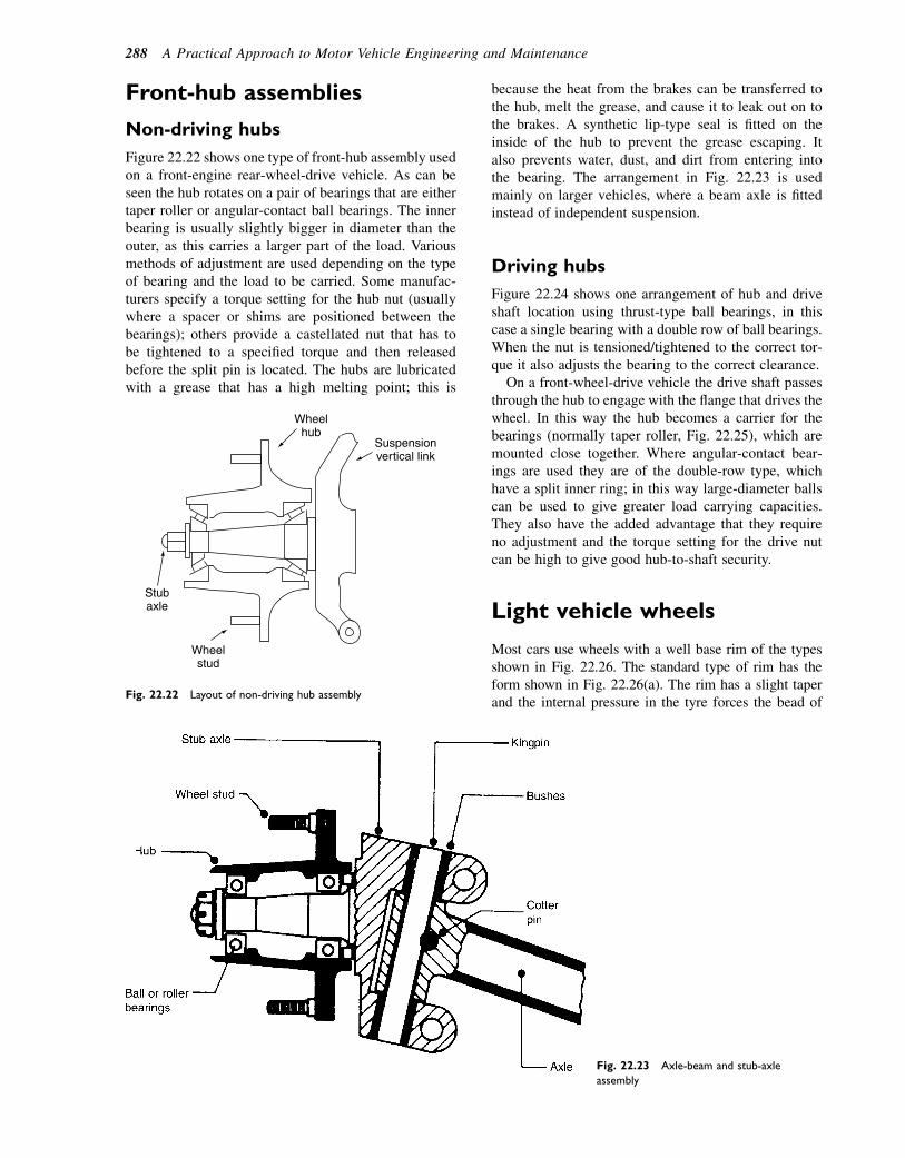
Front-hub assemblies
Non-driving hubs
Figure 22.22 shows one type of front-hub assembly usedon a front-engine rear-wheel-drive vehicle. As can beseen the hub rotates on a pair of bearings that are eithertaper roller or angular-contact ball bearings. The innerbearing is usually slightly bigger in diameter than theouter, as this carries a larger part of the load. Variousmethods of adjustment are used depending on the typeof bearing and the load to be carried. Some manufac-turers specify a torque setting for the hub nut (usuallywhere a spacer or shims are positioned between thebearings); others provide a castellated nut that has tobe tightened to a specified torque and then releasedbefore the split pin is located. The hubs are lubricatedwith a grease that has a high melting point; this is
because the heat from the brakes can be transferred tothe hub, melt the grease, and cause it to leak out on tothe brakes. A synthetic lip-type seal is fitted on theinside of the hub to prevent the grease escaping. Italso prevents water, dust, and dirt from entering intothe bearing. The arrangement in Fig. 22.23 is usedmainly on larger vehicles, where a beam axle is fittedinstead of independent suspension.
Driving hubs
Figure 22.24 shows one arrangement of hub and driveshaft location using thrust-type ball bearings, in thiscase a single bearing with a double row of ball bearings.When the nut is tensioned/tightened to the correct tor-que it also adjusts the bearing to the correct clearance.
On a front-wheel-drive vehicle the drive shaft passesthrough the hub to engage with the flange that drives thewheel. In this way the hub becomes a carrier for thebearings (normally taper roller, Fig. 22.25), which aremounted close together. Where angular-contact bear-ings are used they are of the double-row type, whichhave a split inner ring; in this way large-diameter ballscan be used to give greater load carrying capacities.They also have the added advantage that they requireno adjustment and the torque setting for the drive nutcan be high to give good hub-to-shaft security.
Light vehicle wheels
Most cars use wheels with a well base rim of the typesshown in Fig. 22.26. The standard type of rim has theform shown in Fig. 22.26(a). The rim has a slight taperand the internal pressure in the tyre forces the bead of
Wheelhub
Suspensionvertical link
Wheelstud
Stubaxle
Fig. 22.22 Layout of non-driving hub assembly
Fig. 22.23 Axle-beam and stub-axle
assembly
288 A Practical Approach to Motor Vehicle Engineering and Maintenance
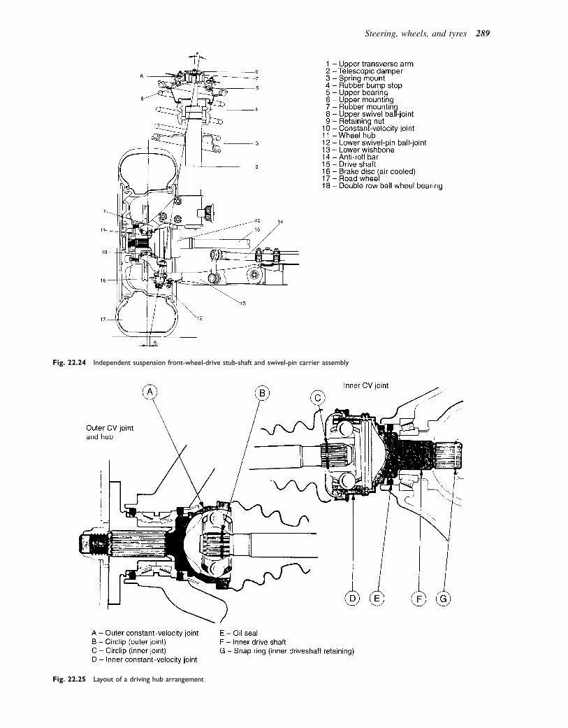
Fig. 22.24 Independent suspension front-wheel-drive stub-shaft and swivel-pin carrier assembly
Fig. 22.25 Layout of a driving hub arrangement
Steering, wheels, and tyres 289

the tyre into tight frictional contact with the wheel. Thistight contact is required so as to maintain an airtightseal and also to provide the grip that will transmit drivingand braking forces between the tyre and the wheel. Thegrip is dependent on the correct tyre pressure being main-tained and, in the event of a puncture, the tyre bead islikely to break away from the wheel rim. The doublehump rim shown in Fig. 22.26(b) is intended to providea more secure fixing for the tyre in the sense that, shoulda puncture occur, the bead of the tyre will be held in placeby the humps and this should provide a degree of controlin the event of a sudden, rapid puncture.
Types of car wheels
Most car wheels are fabricated from steel pressingsand their appearance is often altered by the additionof an embellisher. Figures 22.27 and 22.28 showa range of wheels and wheel trims as used on Ford
Escort vehicles. When weight and possibly ‘sporty’appearance is a consideration cast alloy wheels areused. The metals used are normally aluminium alloy,or magnesium-based alloy, and the wheels are con-structed by casting. An alloy wheel is shown inFig. 22.27(e).
Figures 22.27(f) and 22.27(g) shows the differenttypes of wheel bolts and balance weights that arerequired. The steel wheel uses a bolt with a taper underthe head. This taper screws into a corresponding taperon the wheel and, when the correct torque is applied,the wheel is secured to the vehicle hub. In order toprevent damage to the alloy wheel its bolts are providedwith a tapered washer. The taper on the washer sits inthe taper on the wheel and the bolt can be tightenedwithout ‘tearing’ the alloy of the wheel. Figure 22.27also shows the two different types of wheel balancingweights that are required. The obvious point to makehere is that the steel wheel weight is not suitable foruse on the alloy wheel, and vice versa.
Fig. 22.26 Two types of wheel rim in common use. (a) Standard. (b) Double hump rim
Fig. 22.27 A range of wheels
290 A Practical Approach to Motor Vehicle Engineering and Maintenance
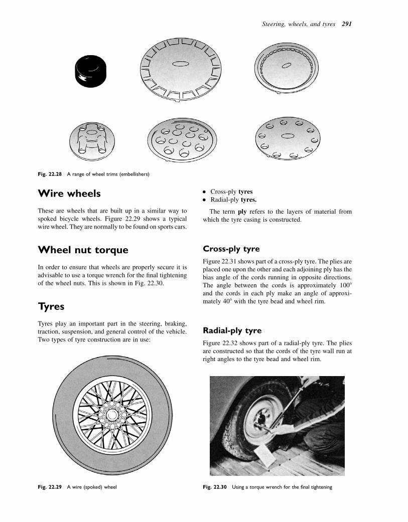
Wire wheels
These are wheels that are built up in a similar way tospoked bicycle wheels. Figure 22.29 shows a typicalwire wheel. They are normally to be found on sports cars.
Wheel nut torque
In order to ensure that wheels are properly secure it isadvisable to use a torque wrench for the final tighteningof the wheel nuts. This is shown in Fig. 22.30.
Tyres
Tyres play an important part in the steering, braking,traction, suspension, and general control of the vehicle.Two types of tyre construction are in use:
� Cross-ply tyres� Radial-ply tyres.
The term ply refers to the layers of material fromwhich the tyre casing is constructed.
Cross-ply tyre
Figure 22.31 shows part of a cross-ply tyre. The plies areplaced one upon the other and each adjoining ply has thebias angle of the cords running in opposite directions.The angle between the cords is approximately 1008and the cords in each ply make an angle of approxi-mately 408 with the tyre bead and wheel rim.
Radial-ply tyre
Figure 22.32 shows part of a radial-ply tyre. The pliesare constructed so that the cords of the tyre wall run atright angles to the tyre bead and wheel rim.
Fig. 22.28 A range of wheel trims (embellishers)
Fig. 22.29 A wire (spoked) wheel Fig. 22.30 Using a torque wrench for the final tightening
Steering, wheels, and tyres 291

Cross-ply versus radial-ply tyres
Radial-ply tyres have a more flexible side wall and this,together with the braced tread, ensures that a greaterarea of tread remains in contact with the road whenthe vehicle is cornering. Figure 22.33 shows the differ-ence between cross-ply and radial-ply tyres when thevehicle is cornering. In effect, radial-ply tyres producea better grip.
It is this remarkable difference between the perfor-mance of cross-ply and radial-ply tyres that leads tothe rules about mixing of cross-ply and radial-ply tyreson a vehicle. Cross-ply tyres on the front axle and radial-ply tyres on the rear axle are the only combination thatcan be used.
Tyre sizes
In general tyres have two size markings, one indicatingthe width of the tyre and other giving the diameter ofthe wheel rim on which the tyre fits. Thus, a 5.20 by10 marking indicates a tyre that is normally 5.20inches wide and fits a 10-inch-diameter wheel rim.Radial-ply tyres have a marking that gives the nominalwidth in millimetres and a wheel rim diameter ininches; for example, a 145e14 tyre is a tyre witha nominal width of 145mm with a wheel rim diameterof 14 inches.
Originally vehicle tyres were of circular cross-sectionand the width of the tyre section was equal to its height.Over the years, developments have led to a considerablechange in the shape of the tyre cross-section and it isnow common to see tyres where the width of thecross-section is greater than its height. These tyresare known as ‘low-profile’ tyres. Modern tyres nowhave an additional number in the size; for example,185/70e13. The 185 is the tyre width in millimetres,the 13 is the rim diameter in inches, and the 70 refersto the fact that the height of the tyre section is 70% ofthe width. This 70% figure is also known as the aspectratio. The aspect ratio 5 (tyre section height/tyresection width) x 100 percent. Tyre size and other infor-mation is carried on the side wall and Fig. 22.34 showshow they appear on a typical tyre.
Load and speed ratings
The tyre load and speed ratings are the figures andletters that refer to the maximum load and speed ratingof a tyre. For example, 82S marked on a tyre meansa load index of 82 and a speed index of S. In this casethe 82 means a load capacity of 475 kg per tyre andthe S relates to a maximum speed of 180 km/h or113 mph. One of the main points about these markings
Fig. 22.31 Cross-ply tyre construction
Fig. 22.32 Radial-ply tyre construction
Fig. 22.33 Cross-ply and radial-ply tyres under cornering
conditions
292 A Practical Approach to Motor Vehicle Engineering and Maintenance
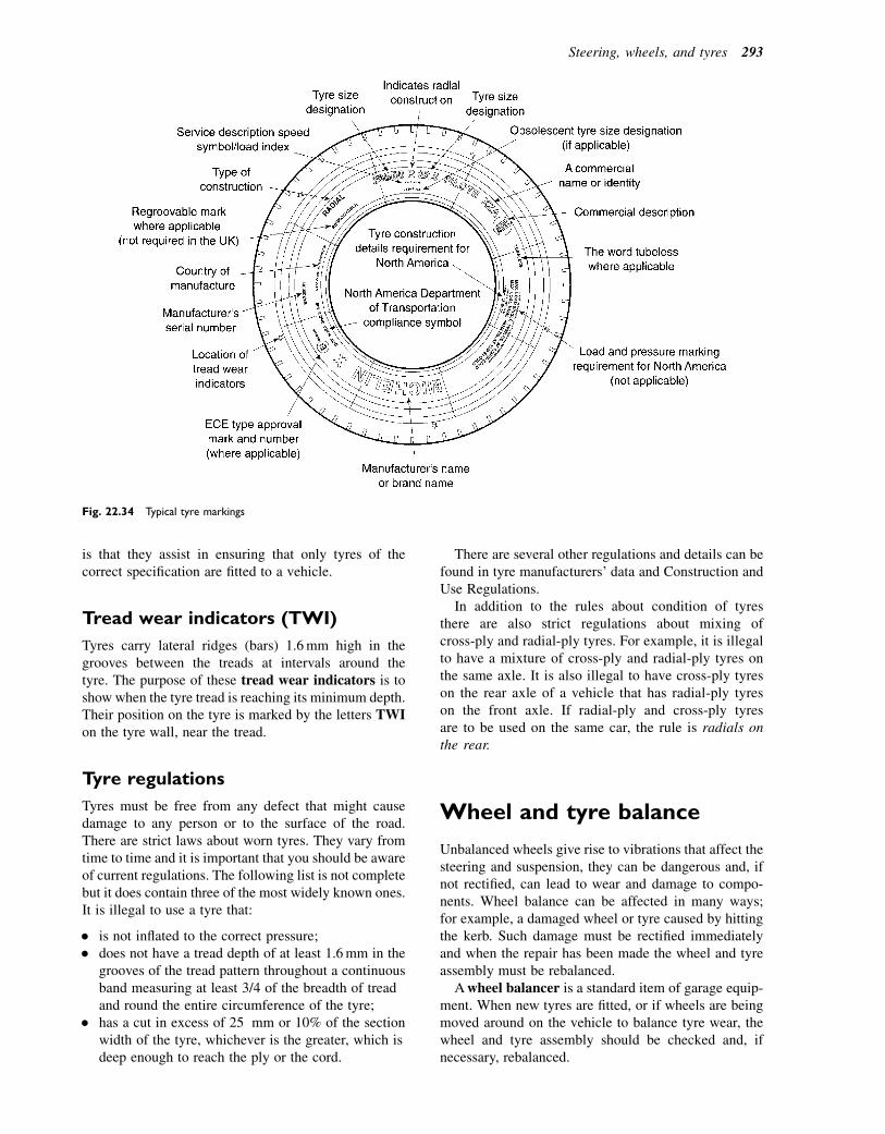
is that they assist in ensuring that only tyres of thecorrect specification are fitted to a vehicle.
Tread wear indicators (TWI)
Tyres carry lateral ridges (bars) 1.6mm high in thegrooves between the treads at intervals around thetyre. The purpose of these tread wear indicators is toshow when the tyre tread is reaching its minimum depth.Their position on the tyre is marked by the letters TWIon the tyre wall, near the tread.
Tyre regulations
Tyres must be free from any defect that might causedamage to any person or to the surface of the road.There are strict laws about worn tyres. They vary fromtime to time and it is important that you should be awareof current regulations. The following list is not completebut it does contain three of the most widely known ones.It is illegal to use a tyre that:
� is not inflated to the correct pressure;� does not have a tread depth of at least 1.6mm in the
grooves of the tread pattern throughout a continuousband measuring at least 3/4 of the breadth of treadand round the entire circumference of the tyre;
� has a cut in excess of 25 mm or 10% of the sectionwidth of the tyre, whichever is the greater, which isdeep enough to reach the ply or the cord.
There are several other regulations and details can befound in tyre manufacturers’ data and Construction andUse Regulations.
In addition to the rules about condition of tyresthere are also strict regulations about mixing ofcross-ply and radial-ply tyres. For example, it is illegalto have a mixture of cross-ply and radial-ply tyres onthe same axle. It is also illegal to have cross-ply tyreson the rear axle of a vehicle that has radial-ply tyreson the front axle. If radial-ply and cross-ply tyresare to be used on the same car, the rule is radials onthe rear.
Wheel and tyre balance
Unbalanced wheels give rise to vibrations that affect thesteering and suspension, they can be dangerous and, ifnot rectified, can lead to wear and damage to compo-nents. Wheel balance can be affected in many ways;for example, a damaged wheel or tyre caused by hittingthe kerb. Such damage must be rectified immediatelyand when the repair has been made the wheel and tyreassembly must be rebalanced.
Awheel balancer is a standard item of garage equip-ment. When new tyres are fitted, or if wheels are beingmoved around on the vehicle to balance tyre wear, thewheel and tyre assembly should be checked and, ifnecessary, rebalanced.
Fig. 22.34 Typical tyre markings
Steering, wheels, and tyres 293
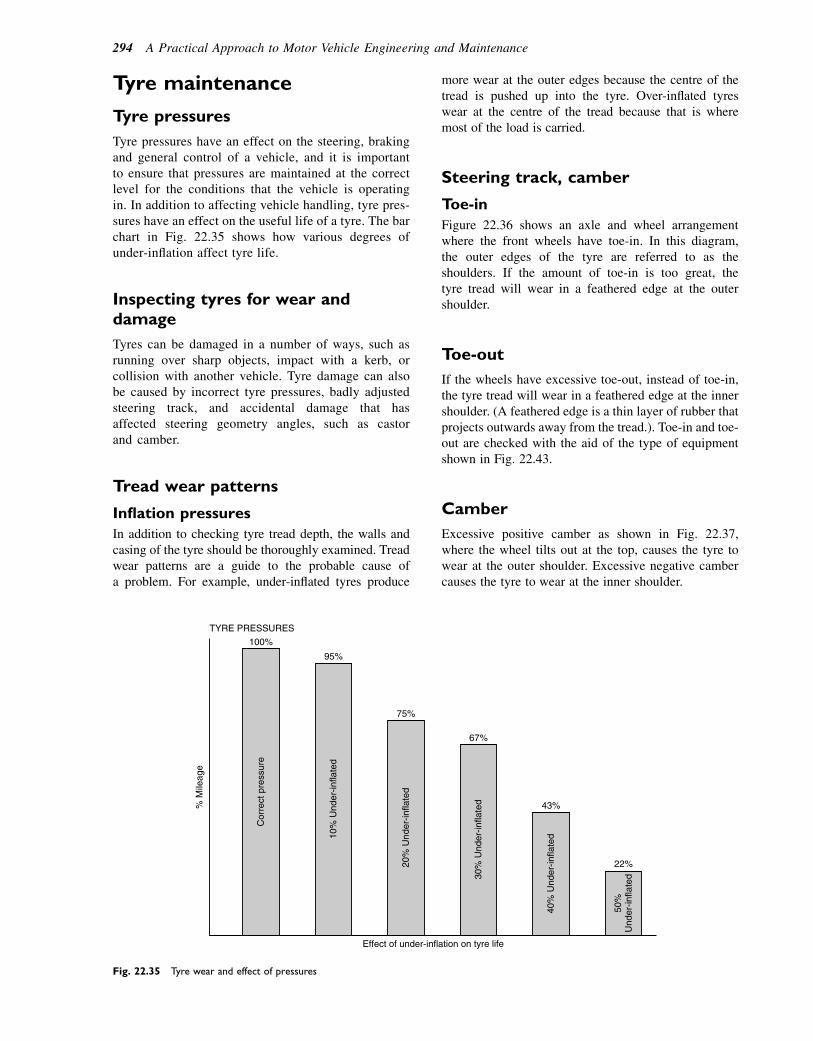
Tyre maintenance
Tyre pressures
Tyre pressures have an effect on the steering, brakingand general control of a vehicle, and it is importantto ensure that pressures are maintained at the correctlevel for the conditions that the vehicle is operatingin. In addition to affecting vehicle handling, tyre pres-sures have an effect on the useful life of a tyre. The barchart in Fig. 22.35 shows how various degrees ofunder-inflation affect tyre life.
Inspecting tyres for wear anddamage
Tyres can be damaged in a number of ways, such asrunning over sharp objects, impact with a kerb, orcollision with another vehicle. Tyre damage can alsobe caused by incorrect tyre pressures, badly adjustedsteering track, and accidental damage that hasaffected steering geometry angles, such as castorand camber.
Tread wear patterns
Inflation pressures
In addition to checking tyre tread depth, the walls andcasing of the tyre should be thoroughly examined. Treadwear patterns are a guide to the probable cause ofa problem. For example, under-inflated tyres produce
more wear at the outer edges because the centre of thetread is pushed up into the tyre. Over-inflated tyreswear at the centre of the tread because that is wheremost of the load is carried.
Steering track, camber
Toe-in
Figure 22.36 shows an axle and wheel arrangementwhere the front wheels have toe-in. In this diagram,the outer edges of the tyre are referred to as theshoulders. If the amount of toe-in is too great, thetyre tread will wear in a feathered edge at the outershoulder.
Toe-out
If the wheels have excessive toe-out, instead of toe-in,the tyre tread will wear in a feathered edge at the innershoulder. (A feathered edge is a thin layer of rubber thatprojects outwards away from the tread.). Toe-in and toe-out are checked with the aid of the type of equipmentshown in Fig. 22.43.
Camber
Excessive positive camber as shown in Fig. 22.37,where the wheel tilts out at the top, causes the tyre towear at the outer shoulder. Excessive negative cambercauses the tyre to wear at the inner shoulder.
TYRE PRESSURES
100%
95%
75%
Effect of under-inflation on tyre life
% M
ileag
e
Cor
rect
pre
ssur
e
10%
Und
er-in
flate
d
20%
Und
er-in
flate
d
30%
Und
er-in
flate
d
40%
Und
er-in
flate
d
50%
U
nder
-infla
ted
67%
43%
22%
Fig. 22.35 Tyre wear and effect of pressures
294 A Practical Approach to Motor Vehicle Engineering and Maintenance
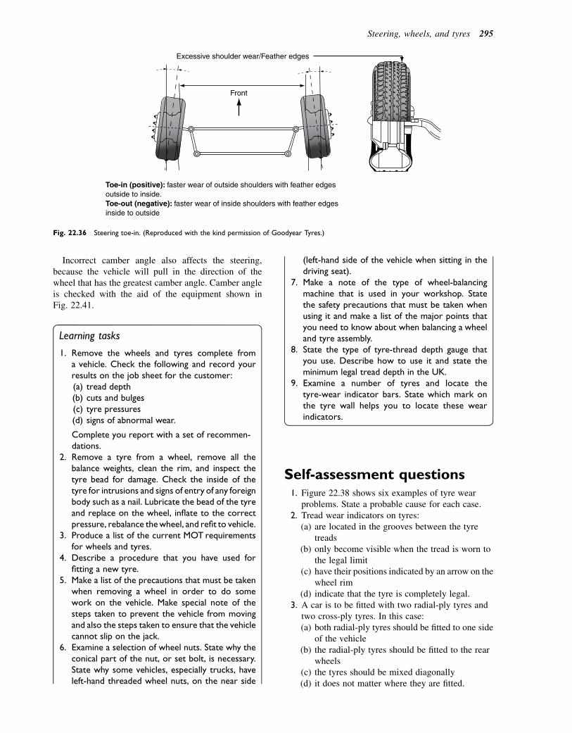
Incorrect camber angle also affects the steering,because the vehicle will pull in the direction of thewheel that has the greatest camber angle. Camber angleis checked with the aid of the equipment shown inFig. 22.41.
Learning tasks
1. Remove the wheels and tyres complete froma vehicle. Check the following and record yourresults on the job sheet for the customer:(a) tread depth(b) cuts and bulges(c) tyre pressures(d) signs of abnormal wear.
Complete you report with a set of recommen-dations.
2. Remove a tyre from a wheel, remove all thebalance weights, clean the rim, and inspect thetyre bead for damage. Check the inside of thetyre for intrusions and signs of entry of any foreignbody such as a nail. Lubricate the bead of the tyreand replace on the wheel, inflate to the correctpressure, rebalance thewheel, and refit to vehicle.
3. Produce a list of the current MOT requirementsfor wheels and tyres.
4. Describe a procedure that you have used forfitting a new tyre.
5. Make a list of the precautions that must be takenwhen removing a wheel in order to do somework on the vehicle. Make special note of thesteps taken to prevent the vehicle from movingand also the steps taken to ensure that the vehiclecannot slip on the jack.
6. Examine a selection of wheel nuts. State why theconical part of the nut, or set bolt, is necessary.State why some vehicles, especially trucks, haveleft-hand threaded wheel nuts, on the near side
(left-hand side of the vehicle when sitting in thedriving seat).
7. Make a note of the type of wheel-balancingmachine that is used in your workshop. Statethe safety precautions that must be taken whenusing it and make a list of the major points thatyou need to know about when balancing a wheeland tyre assembly.
8. State the type of tyre-thread depth gauge thatyou use. Describe how to use it and state theminimum legal tread depth in the UK.
9. Examine a number of tyres and locate thetyre-wear indicator bars. State which mark onthe tyre wall helps you to locate these wearindicators.
Self-assessment questions1. Figure 22.38 shows six examples of tyre wear
problems. State a probable cause for each case.2. Tread wear indicators on tyres:
(a) are located in the grooves between the tyretreads
(b) only become visible when the tread is worn tothe legal limit
(c) have their positions indicated by an arrow on thewheel rim
(d) indicate that the tyre is completely legal.3. A car is to be fitted with two radial-ply tyres and
two cross-ply tyres. In this case:(a) both radial-ply tyres should be fitted to one side
of the vehicle(b) the radial-ply tyres should be fitted to the rear
wheels(c) the tyres should be mixed diagonally(d) it does not matter where they are fitted.
Excessive shoulder wear/Feather edges
Front
Toe-in (positive): faster wear of outside shoulders with feather edges outside to inside. Toe-out (negative): faster wear of inside shoulders with feather edges inside to outside
Fig. 22.36 Steering toe-in. (Reproduced with the kind permission of Goodyear Tyres.)
Steering, wheels, and tyres 295

4. In a tyre size of 185/70e13, the aspect ratio is:(a) 185(b) 70%(c) 13(d) 198.
5. In a steering system that uses a cam and pegsteering box, the drop arm:(a) controls back lash in the mechanism(b) transmits a pullepush motion to the drag link(c) connects the steering arms to the stub axle(d) transmits steering wheel motion to the cam.
6. When checking the steering geometry on a certainvehicle, it is found that the camber angle on thenearside is 2.68 and on the offside it is only 1.28.This difference:(a) may have caused the vehicle to pull to the right(b) may have caused the left front tyre to wear on
the inside edge(c) may have caused the vehicle to pull to the left(d) is not significant.
7. With centre-point steering:(a) the centre of tyre contact meets the road surface
at the same spot as the centre line of the kingpin(b) the vehicle’s centre of turn is on a line that passes
through the centre of gravity of the vehicle(c) the steering gearbox is in the centre of the
vehicle(d) no kingpin inclination or camber angle is
required.
8. Toe out on turns e using turntablesFigures 22.39 and 22.40 show the equipmentand procedure for checking the angles throughwhich the steered wheels are turned through on theleft and right locks.(a) Why does the inside wheel turn through
a greater angle than the outside wheel whena vehicle is turning a corner?
(b) Why is it important to ensure that the track rodlengths are maintained at the correct lengthwhen adjusting the track?
(c) What is the Ackermann principle as applied tosteering.
9. Castor, camber, KPIMeasuring camber angle(a) Check to make sure that the floor is level and
that the tyres are correctly inflated.(b) Hold the gauge in a true vertical position and
adjust the dial marked ‘camber’ so that the ‘0’ isin line with the index mark.
(c) Apply the long edge of the gauge to the tyresidewall holding it in a vertical positione avoidplacing the gauge on the bulge where the tyrerests on the floor.
(d) Turn the camber dial until the bubble inthe spirit level is in the central position e notethe camber angle as shown on the dial.
Positive Excessive shoulder wear
Positive camber (upper wheel part tilted outwards): faster wear of outside shoulder. Negative camber (upper wheel end tilted inwards): faster wear of inside shoulder.
Fig. 22.37 Steering camber angle. (Reproduced with the kind
permission of Goodyear Tyres.)
Rapid wear at shoulders
Rapid wear at centre
Cracked treads
Feathered edge
Bald spots
a b c
Wear on one side
d e f
Fig. 22.38 Tyre tread wear patterns
Fig. 22.39 Steering turntable for checking toe-out on turns (Sealey)
296 A Practical Approach to Motor Vehicle Engineering and Maintenance

Figure 22.42 shows the additional equipmentwhich, together with the turn tables, is used formeasuring castor and kingpin inclination angles.(a) Refer to the Sealey (www.sealey.co.uk)
website and make notes about theprocedure for checking castor and KPIangles.
(b) Explain why it is important to ensure thattyres are in good condition andcorrectly inflated prior to performing steeringchecks.
(c) Wear in steering and suspension componentscan affect steering geometry. Write a list of thecomponents that can affect castor and KPI.
10. Laser type tracking equipment
Note on safety
LASER SAFETY
The GA48 utilises a Class II laser that emits low levelsof visible radiation (i.e. wavelengths between 400 and700 nanometres) which are safe for the skin but notinherently safe for the eyes. The Class II emissionlimit is set at the maximum level for which eyeprotection is normally afforded by natural aversionresponses to bright light. Accidental eye exposure istherefore normally safe, although the natural aver-sion response can be overridden by deliberatelystaring into the beam, and can also be influenced bythe use of alcohol or drugs.
read thisangle ‘X’
read thisangle ‘Y’
LEFT RIGHT
4.3
Set at 20°
Set at 20°
Front of vehicle
LEFT RIGHT (driver)Front of vehicle
Steer to the left by 20° measuredon the right hand wheelscale.
This will result in the left wheelturning to angle ‘X’.
To obtain the toe-in/toe-out anglesubtract 20° from angle ‘X’.
Positive result indicates the degree of toe-outNegative result indicates the degree of toe-in
Steer to the right by 20° measuredon the left hand wheel scale.
To obtain the toe-in/toe-out anglesubtract 20° from angle ‘Y’.
Positive result indicates the degree of toe-out. Negative result indicates thedegree of toe-in.
4.4 To measure FULL LOCK set the equipment up as described above in sections 4.1 and 4.2 and as shown in diagram 1.
4.5 Remove the turntable locking pins.
4.6 Steer the wheels to FULL LEFT LOCK and take a reading from the right hand wheel.
4.7 Steer the wheels to FULL RIGHT LOCK and take a reading from the left hand wheel.
4.8 COMPARE READINGS AND CHECK WITH THE VEHICLE MANUFACTURER’S RECOMMENDATIONS.
Measure the WHEEL ANGLES and the TOE-IN/OUT ANGLES for both left and right steering as described above and below.
COMPARE YOUR READINGS WITH THE VEHICLE MANUFACTURER’S RECOMMENDATIONS.
2
3
This will result in the left wheelturning to angle ‘Y’.
Fig. 22.40 Steering angles
Steering, wheels, and tyres 297

WARNING!DO NOT look or stare into the laser beam as
permanent eye damage could result.DONOT direct the laser beam at any person’s (or
animal’s) eyes as eye damage could result. If the beamis obstructed by a person during use, release thecontact switch immediately.DO NOT use the equipment while under the
influence of alcohol, drugs or whilst on medication.Be aware that reflections of the laser beam
from mirrors or other shiny surfacescan be as hazardous as direct eyeexposure.
The above safety information is taken from Sealeydocumentation. For full instructions on calibration anduse of this equipment refer to the Sealey website(www.sealey.co.uk).
(a)By reference to several workshop manuals, writedown the toe in, or toe out angle for variousvehicles.
(b)With the aid of sketches, describe the means bywhich the track may be adjusted.
11. The type of axle misalignment that is shown inFig. 22.44 may be the result of:
� Collision damage� Impact with an obstruction� Incorrect fitting of components� Worn or corroded body or suspension parts.
Fig. 22.41 Camber gauge in position (Sealey garage equipment)
Fig. 22.42 Castor and KPI gauges (Sealey)
Laser
Mirror
Mirror
Laser device
Calibrated scale
Fig. 22.43 Laser tracking equipment (Sealey)
298 A Practical Approach to Motor Vehicle Engineering and Maintenance
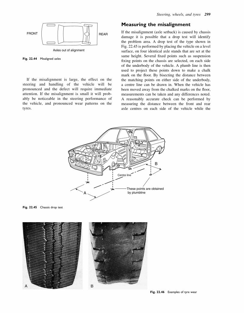
If the misalignment is large, the effect on thesteering and handling of the vehicle will bepronounced and the defect will require immediateattention. If the misalignment is small it will prob-ably be noticeable in the steering performance ofthe vehicle, and pronounced wear patterns on thetyres.
Measuring the misalignment
If the misalignment (axle setback) is caused by chassisdamage it is possible that a drop test will identifythe problem area. A drop test of the type shown inFig. 22.45 is performed by placing the vehicle on a levelsurface, on four identical axle stands that are set at thesame height. Several fixed points such as suspensionfixing points on the chassis are selected, on each sideof the underbody of the vehicle. A plumb line is thenused to project these points down to make a chalkmark on the floor. By bisecting the distance betweenthe matching points on either side of the underbody,a centre line can be drawn in. When the vehicle hasbeen moved away from the chalked marks on the floor,measurements can be taken and any differences noted.A reasonably accurate check can be performed bymeasuring the distance between the front and rearaxle centres on each side of the vehicle while the
FRONT REAR
Axles out of alignment
Fig. 22.44 Misaligned axles
These points are obtained by plumblineA
Centre line
B
Fig. 22.45 Chassis drop test
Fig. 22.46 Examples of tyre wear
Steering, wheels, and tyres 299
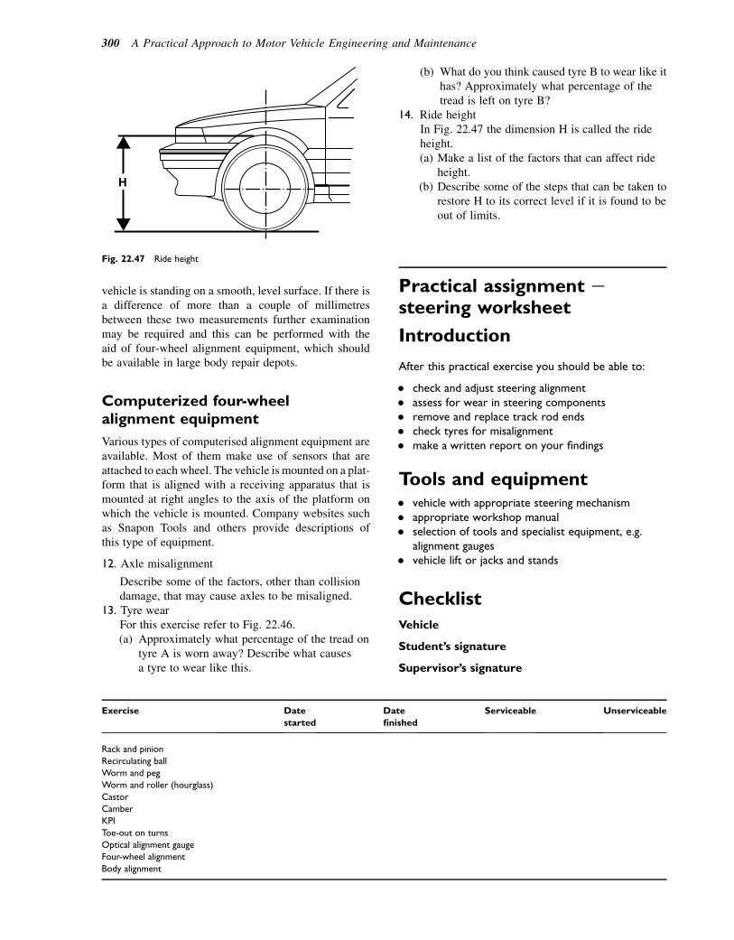
vehicle is standing on a smooth, level surface. If there isa difference of more than a couple of millimetresbetween these two measurements further examinationmay be required and this can be performed with theaid of four-wheel alignment equipment, which shouldbe available in large body repair depots.
Computerized four-wheelalignment equipment
Various types of computerised alignment equipment areavailable. Most of them make use of sensors that areattached to each wheel. The vehicle is mounted on a plat-form that is aligned with a receiving apparatus that ismounted at right angles to the axis of the platform onwhich the vehicle is mounted. Company websites suchas Snapon Tools and others provide descriptions ofthis type of equipment.
12. Axle misalignment
Describe some of the factors, other than collisiondamage, that may cause axles to be misaligned.
13. Tyre wearFor this exercise refer to Fig. 22.46.(a) Approximately what percentage of the tread on
tyre A is worn away? Describe what causesa tyre to wear like this.
Exercise Date
started
Date
finished
Serviceable Unserviceable
Rack and pinion
Recirculating ball
Worm and peg
Worm and roller (hourglass)
Castor
Camber
KPI
Toe-out on turns
Optical alignment gauge
Four-wheel alignment
Body alignment
H
Fig. 22.47 Ride height
(b) What do you think caused tyre B to wear like ithas? Approximately what percentage of thetread is left on tyre B?
14. Ride heightIn Fig. 22.47 the dimension H is called the rideheight.(a) Make a list of the factors that can affect ride
height.(b) Describe some of the steps that can be taken to
restore H to its correct level if it is found to beout of limits.
Practical assignment esteering worksheet
Introduction
After this practical exercise you should be able to:
� check and adjust steering alignment� assess for wear in steering components� remove and replace track rod ends� check tyres for misalignment� make a written report on your findings
Tools and equipment� vehicle with appropriate steering mechanism� appropriate workshop manual� selection of tools and specialist equipment, e.g.
alignment gauges� vehicle lift or jacks and stands
Checklist
Vehicle
Student’s signature
Supervisor’s signature
300 A Practical Approach to Motor Vehicle Engineering and Maintenance
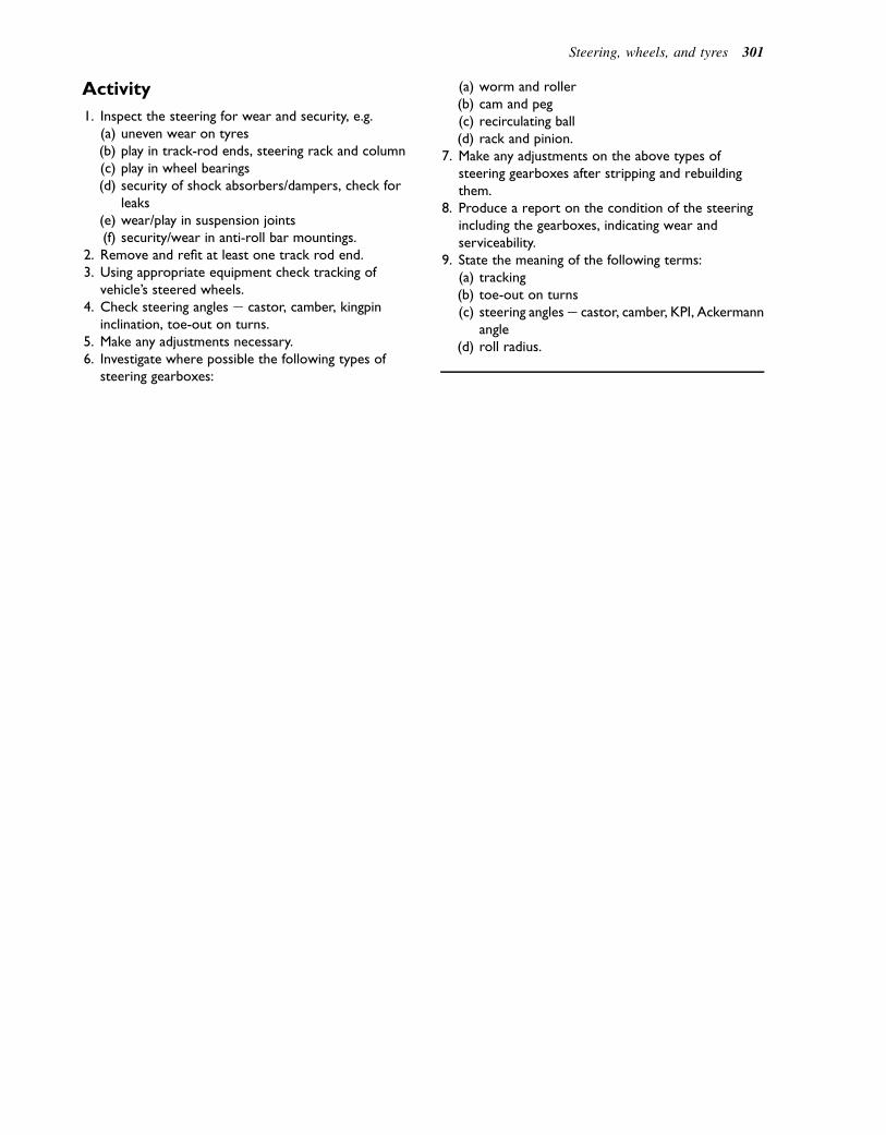
Activity
1. Inspect the steering for wear and security, e.g.(a) uneven wear on tyres(b) play in track-rod ends, steering rack and column(c) play in wheel bearings(d) security of shock absorbers/dampers, check for
leaks(e) wear/play in suspension joints(f) security/wear in anti-roll bar mountings.
2. Remove and refit at least one track rod end.3. Using appropriate equipment check tracking of
vehicle’s steered wheels.4. Check steering angles e castor, camber, kingpin
inclination, toe-out on turns.5. Make any adjustments necessary.6. Investigate where possible the following types of
steering gearboxes:
(a) worm and roller(b) cam and peg(c) recirculating ball(d) rack and pinion.
7. Make any adjustments on the above types ofsteering gearboxes after stripping and rebuildingthem.
8. Produce a report on the condition of the steeringincluding the gearboxes, indicating wear andserviceability.
9. State the meaning of the following terms:(a) tracking(b) toe-out on turns(c) steering anglese castor, camber, KPI, Ackermann
angle(d) roll radius.
Steering, wheels, and tyres 301
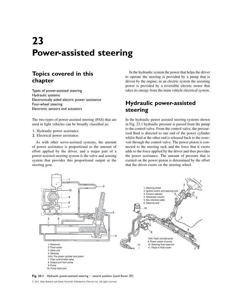
23Power-assisted steering
Topics covered in thischapter
Types of power-assisted steeringHydraulic systemsElectronically aided electric power assistanceFour-wheel steeringElectronic sensors and actuators
The two types of power-assisted steering (PAS) that areused in light vehicles can be broadly classified as:
1. Hydraulic power assistance2. Electrical power assistance.
As with other servo-assisted systems, the amountof power assistance is proportional to the amount ofeffort applied by the driver, and a major part of apower-assisted steering system is the valve and sensingsystem that provides this proportional output at thesteering gear.
In the hydraulic system the power that helps the driverto operate the steering is provided by a pump that isdriven by the engine; in an electric system the assistingpower is provided by a reversible electric motor thattakes its energy from the main vehicle electrical system.
Hydraulic power-assistedsteering
In the hydraulic power assisted steering systems shownin Fig. 23.1 hydraulic pressure is passed from the pumpto the control valve. From the control valve, the pressur-ized fluid is directed to one end of the power cylinderwhilst fluid at the other end is released back to the reser-voir through the control valve. The power piston is con-nected to the steering rack and the force that it exertsadds to the force applied by the driver and thus providesthe power assistance. The amount of pressure that isexerted on the power piston is determined by the effortthat the driver exerts on the steering wheel.
1. Reservoir2. Fluid cooler3. Valve unit4. Steering5 & 6. The power cylinder and piston7. Flow control/relief valve8. Output port from pump9. Pump
10. Pump input port
7 & 9. Track rod ball joints8. Power assist oil pump10. Steering fluid reservoir11. Pipes to fluid cooler
1. Steering wheel2. Ignition switch and steering lock3. Column adjuster4. Telescopic column5. Key interlock cable6. Steering rack
1
3
2
4
5
68
7
11
9
10
1
2
3
10
9
8
7
5 6
4
Fig. 23.1 Hydraulic power-assisted steering e neutral position (Land Rover ZF)
� 2011 Allan Bonnick and Derek Newbold. Published by Elsevier Ltd. All rights reserved
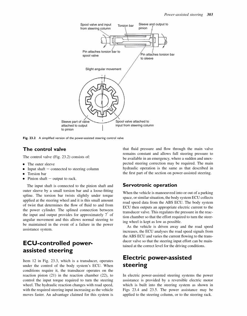
The control valve
The control valve (Fig. 23.2) consists of:
� The outer sleeve� Input shaft e connected to steering column� Torsion bar� Pinion shaft e output to rack.
The input shaft is connected to the pinion shaft andouter sleeve by a small torsion bar and a loose-fittingspline. The torsion bar twists slightly under torqueapplied at the steering wheel and it is this small amountof twist that determines the flow of fluid to and fromthe power cylinder. The splined connection betweenthe input and output provides for approximately 78 ofangular movement and this allows normal steering tobe maintained in the event of a failure in the powerassistance system.
ECU-controlled power-assisted steering
Item 12 in Fig. 23.3, which is a transducer, operatesunder the control of the body system’s ECU. Whenconditions require it, the transducer operates on thereaction piston (21) in the reaction chamber (22), tocontrol the input torque required to turn the steeringwheel. The hydraulic reaction changes with road speed,with the required steering input increasing as the vehiclemoves faster. An advantage claimed for this system is
that fluid pressure and flow through the main valveremains constant and allows full steering pressure tobe available in an emergency, where a sudden and unex-pected steering correction may be required. The mainhydraulic operation is the same as that described inthe first part of the section on power-assisted steering.
Servotronic operation
When the vehicle is manoeuvred into or out of a parkingspace, or similar situation, the body system ECU collectsroad speed data from the ABS ECU. The body systemECU then outputs an appropriate electric current to thetransducer valve. This regulates the pressure in the reac-tion chamber so that the effort required to turn the steer-ing wheel is kept as low as possible.
As the vehicle is driven away and the road speedincreases, the ECU analyses the road speed signals fromthe ABS ECU and varies the current flowing to the trans-ducer valve so that the steering input effort can be main-tained at the correct level for the driving conditions.
Electric power-assistedsteering
In electric power-assisted steering systems the powerassistance is provided by a reversible electric motorwhich is built into the steering system as shown inFigs 23.4 and 23.5. The power assistance may beapplied to the steering column, or to the steering rack.
Spool valve attached toinput from steering column
Sleeve part of valveattached to outputto pinion
Slight angular movement
Pin attaches torsion barto sleeve
Pin attaches torsion bar tospool valve
Spool valve and inputfrom steering column
Torsion bar Sleeve and output topinion
Fig. 23.2 A simplified version of the power-assisted steering control valve
Power-assisted steering 303
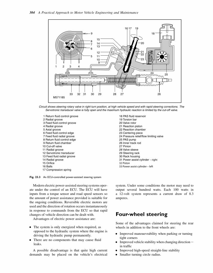
Modern electric power-assisted steering systems oper-ate under the control of an ECU. The ECU will haveinputs from a torque sensor and road speed sensors sothe amount of power assistance provided is suitable forthe ongoing conditions. Reversible electric motors areused and the direction of rotation occurs instantaneouslyin response to commands from the ECU so that rapidchanges of vehicle direction can be dealt with.
Advantages of electric power assistance are:
� The system is only energized when required, asopposed to the hydraulic system where the engine isdriving the hydraulic pump permanently.
� There are no components that may cause fluidleaks.
A possible disadvantage is that quite high currentdemands may be placed on the vehicle’s electrical
system. Under some conditions the motor may need tooutput several hundred watts. Each 100 watts ina 12-volt system represents a current draw of 8.3amperes.
Four-wheel steering
Some of the advantages claimed for steering the rearwheels in addition to the front wheels are:
� Improved manouevrability when parking or turningtight corners
� Improved vehicle stability when changing directionein traffic
� Improved high-speed straight-line stability� Smaller turning circle radius.
15
16 17 19
18
20
2122
23
24 25
2627282930313233
Circuit shows steering rotary valve in right turn position, at high vehicle speed and with rapid steering corrections. TheServotronic transducer valve is fully open and the maximum hydraulic reaction is limited by the cut-off valve.
M571185
1 Return fluid control groove 2 Radial groove 3 Feed fluid control groove 4 Radial groove 5 Axial groove 6 Feed fluid control edge 7 Feed fluid radial groove 8 Retum fluid control edge 9 Retum fluid chamber10 Cut-off valve11 Radial groove12 Servotronic transducer13 Feed fluid radial groove14 Radial groove15 Orifice16 Balls17 Compression spring
18 PAS fluid reservoir19 Torsion bar20 Valve rotor21 Reaction piston22 Reaction chamber23 Centering piece24 Pressure relief/flow limiting valve25 PAS pump26 Inner track rod27 Pinion28 Valve sleeve29 Steering rack30 Rack housing31 Power assist cylinder – right32 Piston33 Power assist cylinder – left
1413
121110
94321
9
87
5
6
Fig. 23.3 An ECU-controlled power-assisted steering system
304 A Practical Approach to Motor Vehicle Engineering and Maintenance
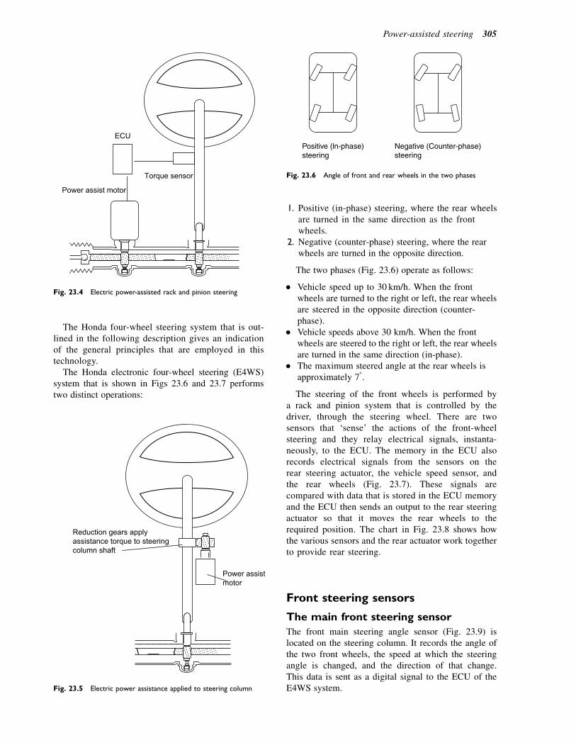
The Honda four-wheel steering system that is out-lined in the following description gives an indicationof the general principles that are employed in thistechnology.
The Honda electronic four-wheel steering (E4WS)system that is shown in Figs 23.6 and 23.7 performstwo distinct operations:
1. Positive (in-phase) steering, where the rear wheelsare turned in the same direction as the frontwheels.
2. Negative (counter-phase) steering, where the rearwheels are turned in the opposite direction.
The two phases (Fig. 23.6) operate as follows:
� Vehicle speed up to 30 km/h. When the frontwheels are turned to the right or left, the rear wheelsare steered in the opposite direction (counter-phase).
� Vehicle speeds above 30 km/h. When the frontwheels are steered to the right or left, the rear wheelsare turned in the same direction (in-phase).
� The maximum steered angle at the rear wheels isapproximately 78.
The steering of the front wheels is performed bya rack and pinion system that is controlled by thedriver, through the steering wheel. There are twosensors that ‘sense’ the actions of the front-wheelsteering and they relay electrical signals, instanta-neously, to the ECU. The memory in the ECU alsorecords electrical signals from the sensors on therear steering actuator, the vehicle speed sensor, andthe rear wheels (Fig. 23.7). These signals arecompared with data that is stored in the ECU memoryand the ECU then sends an output to the rear steeringactuator so that it moves the rear wheels to therequired position. The chart in Fig. 23.8 shows howthe various sensors and the rear actuator work togetherto provide rear steering.
Front steering sensors
The main front steering sensor
The front main steering angle sensor (Fig. 23.9) islocated on the steering column. It records the angle ofthe two front wheels, the speed at which the steeringangle is changed, and the direction of that change.This data is sent as a digital signal to the ECU of theE4WS system.
ECU
Power assist motor
Torque sensor
Fig. 23.4 Electric power-assisted rack and pinion steering
Power assistmotor
Reduction gears applyassistance torque to steeringcolumn shaft
Fig. 23.5 Electric power assistance applied to steering column
Positive (ln-phase)steering
Negative (Counter-phase)steering
Fig. 23.6 Angle of front and rear wheels in the two phases
Power-assisted steering 305

The front steering sub-sensor
The sub-steering angle sensor is located on the frontsteering gearbox. It measures the steering angle on thetwo front wheels and sends an analogue signal to theE4WS-ECU. Its function is to detect:
1. Steering rack position2. Neutral position3. Absolute position of the front main sensor.
The front sub-steering angle sensor (Fig. 23.10) usesa spring-loaded plunger that rides in a sloped groove in
VehicleSpeed sensor
Calculation of the car’s speed
Calculation of motor driving voltage
Rear main steering angle sensor
Rear sub-steering angle sensor
Rear steering actuator (motor)
ECU . Control unit
Rear wheel sensors
Power circuit
Calculation of the steering angle for rear wheels
Front main steering angle sensor
Front sub-steering angle sensor
Calculation of steering rotationspeed
Fig. 23.8 ECU inputs and outputs
Steering gearbox
Left-rear speed sensor
Rear steering actuator
Vehicle speed sensor
Front sub-streering angle sensor
Front main steering angle sensor
4WS control unit and fail safe relay
Fig. 23.7 Layout of the components of the Honda four-wheel steering system
306 A Practical Approach to Motor Vehicle Engineering and Maintenance

the rack. As the rack turns the front wheels, the plungerrides up the slope and causes the sensor element to trans-mit an analogue voltage signal to the ECU. The plunger’sposition is used to determine how far the rack is turned.
The rear steering actuator
The rear steering actuator (Fig. 23.11) is a reversibleelectric motor that causes a nut to rotate arounda threaded part of the rack; in order to keep friction toa minimum the threaded portion runs on ball bearings.
Rear main steering angle sensor
The rear main steering angle sensor (Fig. 23.12) ismounted on the rear actuator. It records the steering angle
Rack
Sub-steering anglesensor
Tapered section of rack
Plunger slides on rackPushes the slider of the sensor
Fig. 23.10 The front steering sub-sensor
Phototransistor
Slit
Rotary disk
Slit
Fig. 23.9 Front steering sensor
Hall IC element
Magnetic pulser ring
Magnetic resistor element
Nut rotated by motor armature
Rear track rod
Threaded rackReversible electric motor
Rear track rod
Fig. 23.11 The rear steering actuator and main sensor
Power-assisted steering 307
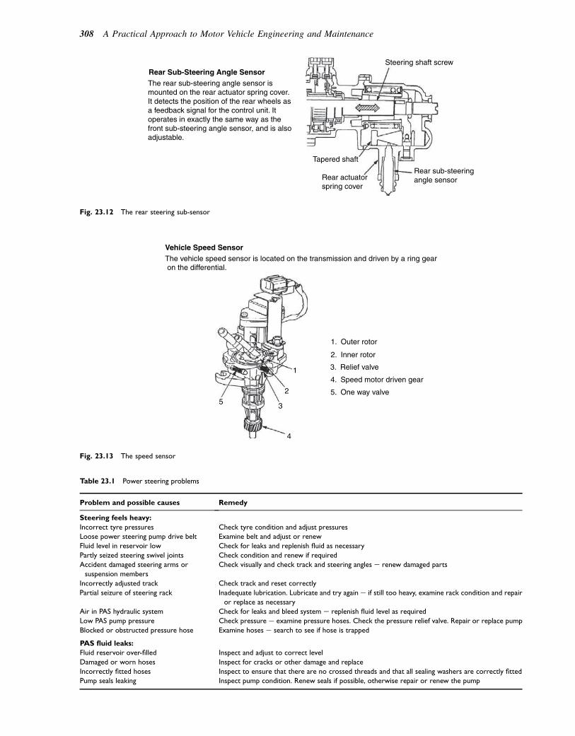
1. Outer rotor
1
3
25
4
The vehicle speed sensor is located on the transmission and driven by a ring gear on the differential.
Vehicle Speed Sensor
2. Inner rotor
3. Relief valve
4. Speed motor driven gear
5. One way valve
Fig. 23.13 The speed sensor
Table 23.1 Power steering problems
Problem and possible causes Remedy
Steering feels heavy:
Incorrect tyre pressures Check tyre condition and adjust pressures
Loose power steering pump drive belt Examine belt and adjust or renew
Fluid level in reservoir low Check for leaks and replenish fluid as necessary
Partly seized steering swivel joints Check condition and renew if required
Accident damaged steering arms or
suspension members
Check visually and check track and steering angles e renew damaged parts
Incorrectly adjusted track Check track and reset correctly
Partial seizure of steering rack Inadequate lubrication. Lubricate and try again e if still too heavy, examine rack condition and repair
or replace as necessary
Air in PAS hydraulic system Check for leaks and bleed system e replenish fluid level as required
Low PAS pump pressure Check pressure e examine pressure hoses. Check the pressure relief valve. Repair or replace pump
Blocked or obstructed pressure hose Examine hoses e search to see if hose is trapped
PAS fluid leaks:
Fluid reservoir over-filled Inspect and adjust to correct level
Damaged or worn hoses Inspect for cracks or other damage and replace
Incorrectly fitted hoses Inspect to ensure that there are no crossed threads and that all sealing washers are correctly fitted
Pump seals leaking Inspect pump condition. Renew seals if possible, otherwise repair or renew the pump
Tapered shaft
Rear sub-steeringangle sensor
Rear Sub-Steering Angle SensorThe rear sub-steering angle sensor ismounted on the rear actuator spring cover.It detects the position of the rear wheels asa feedback signal for the control unit. Itoperates in exactly the same way as thefront sub-steering angle sensor, and is alsoadjustable.
Steering shaft screw
Rear actuatorspring cover
Fig. 23.12 The rear steering sub-sensor
308 A Practical Approach to Motor Vehicle Engineering and Maintenance
of the rearwheels and sends a digital signalwith this infor-mation to the ECU. The speed sensor (Fig. 23.13) is usedby the ECU to determine when to switch between modes.
Diagnostics
In common with other ECU-controlled systems, thefour-wheel steering ECU constantly monitors inputsand outputs; should any of these cease to functioncorrectly the ECU generates a warning and a diagnostictrouble code (DTC). The procedure for retrieving theseDTCs is contained in the workshop manual. In the eventof a serious fault the rear steering is returned to and heldin the straight-ahead position.
Power steering problems, possible causes andremedies are summarized in Table 23.1.
Self-assessment questions1. Which component of a hydraulic power assisted
steering system ensures that the amount of power
assistance applied is proportionate to theeffort that the driver applies to thesteering wheel?
2. In which direction do the rear wheels point whena vehicle with four-wheel steering is moving at slowspeed?
3. Which component in a hydraulic power assistedsteering system generates the hydraulic pressurethat is applied to the power piston?
4. What is the function of the reversible electricmotor in an electric power assistedsteering system?
5. What is the maximum steered angle of the rearwheels in a four-wheel steering system?
6. What is the function of the front mainsteering sensor in a four-wheel steering system?
7. What type of fluid is used in hydraulic power assistedsteering systems?
8. What is the function of the electronically controlledactuator at the rear wheels of a four-wheel steeringsystem?
Power-assisted steering 309

24Computer (ECU)-controlled systems
Topics covered in thischapter
The ECU as a computerFault codesNetworking and bus systemsCANThe CAN busHigh-speed and low-speed CANData transmission ratesError protectionISO 9141 system for fault code accessThe gatewayAlternative networksMultiplexingPower supply and driversEuropean on-board diagnostics (EOBD)Malfunction indicator lamp (MIL)Engine management systemFeedback systemOxygen sensorExhaust gas recirculationTraction controlElectronic throttleStability control
Electronic control units (ECUs) are computers that areused in many applications on motor vehicles. An ECUconsists of a central processor, or microcontroller, anda range of electronic devices that permit the computingunit to interact with vehicle systems. The ECU hasa memory in which the program for controlling a systemis stored. In operation the ECU receives a constantstream of data from various sensors, which it thenprocesses and compares with data in the memory. Theprocessing takes place almost instantaneously andwhen it is completed signals are sent to the actuatorsto make them perform the required action which, inthe case of petrol injectors, will be the amount of fuelto be injected.
The ECU memory consists of permanent memory(ROM) in which the control program is stored, and
a working memory (RAM) that holds data while it isbeing worked on. ROM is permanent memory that canonly be changed by deliberate action, in which casethe memory is called EEPROM, which stands for elec-trically erasable programmable read-only memory.RAM stands for random access memory and it is saidto be ‘volatile memory’ because it is lost when the elec-tricity supply is removed.
Because the ECU is constantly monitoring manyinputs and outputs it is able to detect problems inthe circuits and systems that it controls. Whena problem occurs, fault codes are flagged up anda record called a freeze frame is held in workingmemory. In European on-board diagnostics systems(EOBD) any fault in an emissions-related systemmust cause the malfunction indicator lamp (MIL) tobe illuminated.
The fundamental parts ofa computer
Figure 24.1 shows the general form of a computer,which consists of the following parts:
1. A central processing unit (CPU)2. Input and output devices (I/O)3. Memory4. A program5. A clock for timing purposes.
Data processing is one of the main functions thatcomputers perform. Data, in computer terms, is therepresentation of facts or ideas in a special way thatallows it to be used by the computer. In the case ofdigital computers this usually means binary data, wherenumbers and letters are represented by codes made upof zeros and ones. The input and output interfacesenable the computer to read inputs and to make therequired outputs. Processing is the manipulation andmovement of data, and this is controlled by the clock.Memory is required to hold the main operatingprogram and to temporarily hold data while it is beingworked on.
� 2011 Allan Bonnick and Derek Newbold. Published by Elsevier Ltd. All rights reserved

Computer memory
Read-only memory (ROM)
The ROM is the place where the operating program forthe computer is placed. It consists of an electroniccircuit that gives certain outputs for predetermined inputvalues. ROMs have large storage capacity. It is a perma-nent memory that is built into the computer at theproduction stage.
Read and write, or random accessmemory (RAM)
The RAM is the place where data is held temporarilywhile it is being worked on by the processing unit.Placing data in memory is ‘writing’ and the process ofusing this data is called ‘reading’. RAM is also knownas volatile memory because the data is held there elec-trically and when the source of electricity is removedthe contents of the memory are lost.
Keep-alive memory (KAM)
The term keep-alive memory (KAM) refers to thesystems where the ECM has a permanent, fused, supplyof electricity. Here the fault codes are preserved, butonly while there is battery power.
EEPROMs
Electrically erasable programmable read-only memo-ries (EEPROMs) are sometimes used for the storageof fault codes and other data relating to events con-nected with the vehicle system. This type of memoryis sustained even when power is removed.
The clock
The clock is an electronic circuit that utilizes the piezo-electric effect of a quartz crystal to produce accurately
timed electrical pulses that are used to control theactions of the computer. Clock speeds are measured inthe number of electrical pulses generated in 1 second.One pulse per second is 1 hertz and most computerclocks operate in millions of pulses per second. Onemillion pulses per second is 1 megahertz (1 MHz).
A practical automotivecomputer system
Figure 24.2 shows a computer controlled transmissionsystem. At the heart of the system is an electronicmodule, or ECU. This particular module is a self-con-tained computer that is also known as a microcontroller.Microcontrollers are available in many sizes, e.g. 4-, 8-,16-, and 32-bit, which refers to the length of the binarycode words that they work on. The microcontroller inthis transmission is an 8-bit one.
Figure 24.3 shows some of the internal detail of thecomputer and the following description gives an insightinto the way that it operates:
1. The microcomputer. This is an 8-bitmicrocontroller. In computer language a bit is a 0 ora 1. The 0 normally represents zero or low voltageand the 1 normally represents a higher voltage,probably 1.9 volts. The microcontroller integratedcircuit (chip) has an ROM capacity of 2049 bytes.There are 8 bits to 1 byte. There is also an RAM thatholds 64 bytes. The microcontroller also has an on-chip capacity to convert four analogue inputs into9-bit digital codes.
2. The power supply is a circuit that takes its supplyfrom the vehicle battery. It then provides a regulatedd.c. supply of 5 volts to the microcontroller and thisis its working voltage. The power supply alsoincludes protection against over-voltage and low
Memory
Central processing
unit (CPU)
Clock
Crystal
Fuel injectionOutputs Inputs
EGR valve
Speed sensor
Air flow sensor
Temperature sensor
Program
Fig. 24.1 The basic components of a computer system
Computer (ECU)-controlled systems 311

voltage. The low-voltage protection is required ifbattery voltage is low and it often takes the form ofa capacitor.
3. The clock circuit. In this particular application theclock operates at 4 MHz. The clock controls theactions of the computer such as counting sensorpulses to determine speed and timing of outputpulses to the electro-valves so that gear changes takeplace smoothly and at the required time.
4. The input interface. The input interface (4) containsthe electronic circuits that provide the electricalpower for the sensors and switches that are connectedto it. Some of these inputs are in electrical form(analogue) that cannot be read directly into thecomputer and these inputs must be converted intocomputer (digital) form at the interface.
5. The output (power) interface. The power driver (5)consists of power transistors that are switchedelectronically to operate electro-valves that operatethe gear change hydraulics.
6. Feedback (at 6). On the diagram the inscription reads‘Reading electrical state’. This means that thecomputer is being made aware of the positions (on oroff) of the electro-valves.
7. The watchdog. The watchdog circuit (7) is a timercircuit that prevents the computer from going into anendless loop that can sometimes happen if falsereadings occur.
8. The diagnostic interface. The diagnostic interface (8)is a circuit that causes a warning lamp to beilluminated in case of a system malfunction and itcan also be used to connect to the diagnostic kit.
Fault codes
When a microcontroller (computer) is controlling theoperation of an automotive system such as enginemanagement it is constantly taking readings froma range of sensors. These sensor readings are comparedwith readings held in the operating program and if thesensor reading accords with the program value in theROM the microcontroller will make decisions aboutthe required output to actuators, such as injectors. Ifthe sensor reading is not within limits it will be readagain and if it continues to be ‘out of limits’ a faultcode will be stored in a section of RAM. It is also prob-able that the designer will have written the mainprogram so that the microcontroller will cause thesystem to operate on different criteria until a repaircan be made, or until the fault has cleared. The faultcodes, or diagnostic trouble codes (DTCs) as they aresometimes called, are of great importance to servicetechnicians and the procedures for gaining access tothem need to be understood. It should be clear that, ifthey are held in ordinary RAM, they will be erasedwhen the ECM power is removed and that is why
Fig. 24.2 A computer-controlled transmission system
312 A Practical Approach to Motor Vehicle Engineering and Maintenance
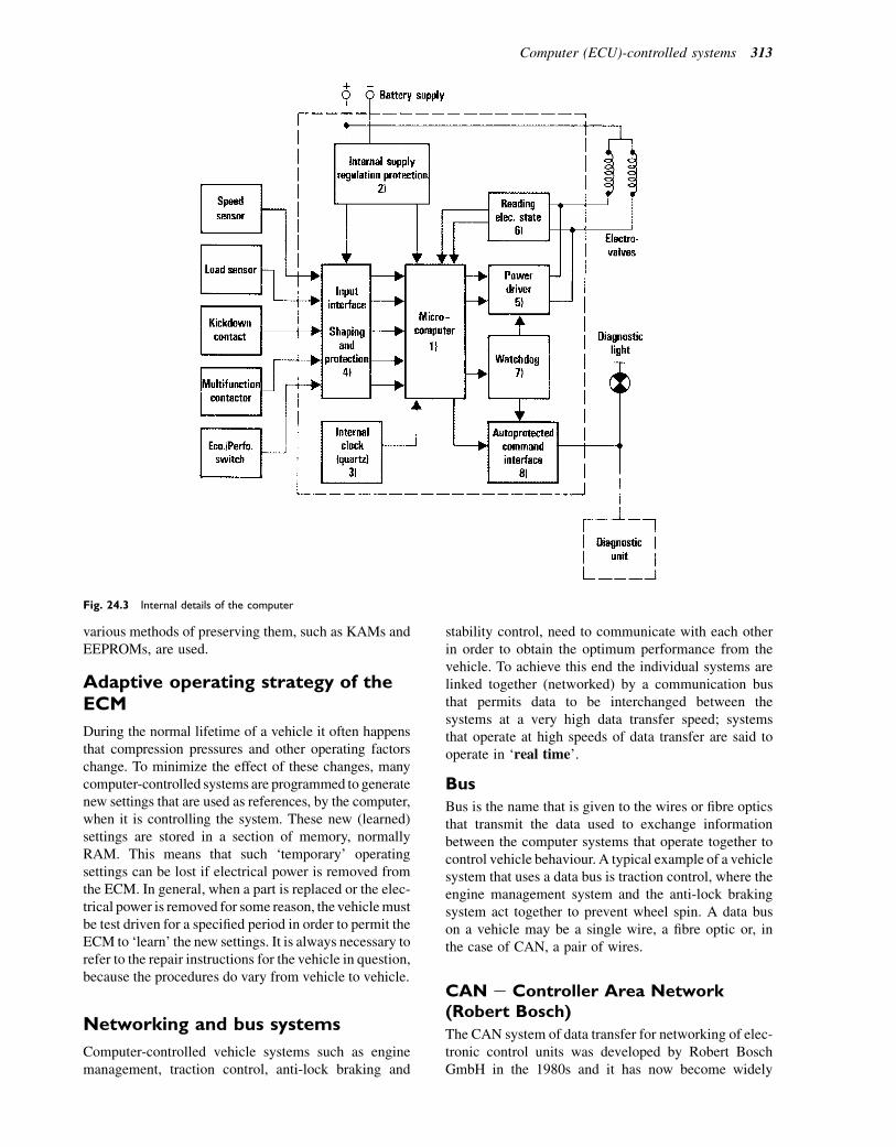
various methods of preserving them, such as KAMs andEEPROMs, are used.
Adaptive operating strategy of theECM
During the normal lifetime of a vehicle it often happensthat compression pressures and other operating factorschange. To minimize the effect of these changes, manycomputer-controlled systems are programmed to generatenew settings that are used as references, by the computer,when it is controlling the system. These new (learned)settings are stored in a section of memory, normallyRAM. This means that such ‘temporary’ operatingsettings can be lost if electrical power is removed fromthe ECM. In general, when a part is replaced or the elec-trical power is removed for some reason, the vehiclemustbe test driven for a specified period in order to permit theECM to ‘learn’ the new settings. It is always necessary torefer to the repair instructions for the vehicle in question,because the procedures do vary from vehicle to vehicle.
Networking and bus systems
Computer-controlled vehicle systems such as enginemanagement, traction control, anti-lock braking and
stability control, need to communicate with each otherin order to obtain the optimum performance from thevehicle. To achieve this end the individual systems arelinked together (networked) by a communication busthat permits data to be interchanged between thesystems at a very high data transfer speed; systemsthat operate at high speeds of data transfer are said tooperate in ‘real time’.
Bus
Bus is the name that is given to the wires or fibre opticsthat transmit the data used to exchange informationbetween the computer systems that operate together tocontrol vehicle behaviour. A typical example of a vehiclesystem that uses a data bus is traction control, where theengine management system and the anti-lock brakingsystem act together to prevent wheel spin. A data buson a vehicle may be a single wire, a fibre optic or, inthe case of CAN, a pair of wires.
CAN e Controller Area Network(Robert Bosch)
The CAN system of data transfer for networking of elec-tronic control units was developed by Robert BoschGmbH in the 1980s and it has now become widely
Fig. 24.3 Internal details of the computer
Computer (ECU)-controlled systems 313
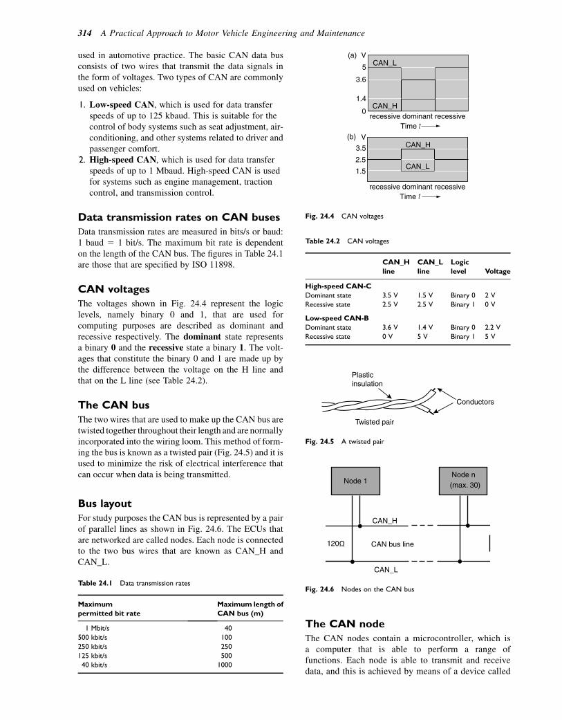
used in automotive practice. The basic CAN data busconsists of two wires that transmit the data signals inthe form of voltages. Two types of CAN are commonlyused on vehicles:
1. Low-speed CAN, which is used for data transferspeeds of up to 125 kbaud. This is suitable for thecontrol of body systems such as seat adjustment, air-conditioning, and other systems related to driver andpassenger comfort.
2. High-speed CAN, which is used for data transferspeeds of up to 1 Mbaud. High-speed CAN is usedfor systems such as engine management, tractioncontrol, and transmission control.
Data transmission rates on CAN buses
Data transmission rates are measured in bits/s or baud:1 baud 5 1 bit/s. The maximum bit rate is dependenton the length of the CAN bus. The figures in Table 24.1are those that are specified by ISO 11898.
CAN voltages
The voltages shown in Fig. 24.4 represent the logiclevels, namely binary 0 and 1, that are used forcomputing purposes are described as dominant andrecessive respectively. The dominant state representsa binary 0 and the recessive state a binary 1. The volt-ages that constitute the binary 0 and 1 are made up bythe difference between the voltage on the H line andthat on the L line (see Table 24.2).
The CAN bus
The two wires that are used to make up the CAN bus aretwisted together throughout their length and are normallyincorporated into the wiring loom. This method of form-ing the bus is known as a twisted pair (Fig. 24.5) and it isused to minimize the risk of electrical interference thatcan occur when data is being transmitted.
Bus layout
For study purposes the CAN bus is represented by a pairof parallel lines as shown in Fig. 24.6. The ECUs thatare networked are called nodes. Each node is connectedto the two bus wires that are known as CAN_H andCAN_L.
The CAN node
The CAN nodes contain a microcontroller, which isa computer that is able to perform a range offunctions. Each node is able to transmit and receivedata, and this is achieved by means of a device called
Table 24.1 Data transmission rates
Maximum
permitted bit rate
Maximum length of
CAN bus (m)
1 Mbit/s 40
500 kbit/s 100
250 kbit/s 250
125 kbit/s 500
40 kbit/s 1000
CAN_L
CAN_H
V
5
3.6
1.4
0
recessive dominant recessive
recessive dominant recessive
V
1.5
2.5
3.5
(b)
(a)
Time
t
t
CAN_H
CAN_L
Time
Fig. 24.4 CAN voltages
Table 24.2 CAN voltages
CAN_H
line
CAN_L
line
Logic
level Voltage
High-speed CAN-C
Dominant state 3.5 V 1.5 V Binary 0 2 V
Recessive state 2.5 V 2.5 V Binary 1 0 V
Low-speed CAN-B
Dominant state 3.6 V 1.4 V Binary 0 2.2 V
Recessive state 0 V 5 V Binary 1 5 V
Plasticinsulation
Conductors
Twisted pair
Fig. 24.5 A twisted pair
Node 1Node n(max. 30)
120
CAN_H
CAN_L
CAN bus line
Fig. 24.6 Nodes on the CAN bus
314 A Practical Approach to Motor Vehicle Engineering and Maintenance
a transceiver. Each message on the bus is read by allnodes but the message is only used by thosenodes that require it. This is achieved by means ofan identifier code that is incorporated into themessage.
Should two nodes attempt to connect to the bussimultaneously there is a risk that a collision mayoccur, resulting in incorrect working of systems. Inorder to prevent this happening, a system known as‘wired AND’ is used; in effect, when the bus hasa binary 0 it will only accept an input of the samevalue. In general, if two messages are trying to accessthe bus simultaneously the one whose identifier hasthe lowest binary value will be given access.
Error protection
Because vehicle systems operate under a wide range ofhostile conditions, such as varying temperatures every hot and very cold e and varying voltages, thereis a risk of errors. To guard against this, checks aremade and when an error in data occurs CAN deviceskeep a count of the number of times that the erroroccurs. CAN devices are able to distinguish betweentemporary errors and permanent ones. When a deviceis deemed to be permanently defective it disconnectsitself electrically from the network. Under such condi-tions the remainder of the network continues tofunction.
Cyclic redundancy check (CRC) errordetection
Messages that are transmitted to the data bus arechecked by the transmitting device and the receivingdevice using a mathematical process that incorporatesa cyclic redundancy code. If the message at thereceiving end does not match that sent by the transmit-ting device the message is rejected.
Types of CAN
High-speed CAN (CAN-C) conforms to ISO Standard11898-2 and operates at 125 kbit/s up to 1 Mbit/s. It isused for those systems that operate in real time, such as:
� Engine management� Transmission control, including traction control� Electronic and anti-lock braking systems� Vehicle stability systems� Instrument cluster.
Low-speed CAN (CAN-B) is covered by ISO Stan-dard 11898-3 and it operates at data transmission speedsof 5 kbit/s up to 125 kbit/s. It is used for comfortand convenience systems and others in the body area,such as:
� Air-conditioning
� Lighting system� Seat adjustment� Mirrors� Sliding sun-roof� Doors.
Number of nodes on a CAN network
Should one system that is connected to the CAN busfail, the other systems on the bus continue to function.Systems can be added. In most road vehicle applicationsthe number of nodes on a CAN bus is limited toa maximum of 30.
ISO 9141 diagnostic bus system
The International Standards Organization (ISO)develops standards for vehicle bus systems; a significantone that applies to vehicle systems is known as ISO9141. The ISO 9141 diagnostic bus system is a systemthat networks vehicle computer control units fordiagnostic purposes. The ISO 9141 system may bea single wire known as the K-line (Fig. 24.7), or itmay be a two-wire system when the wires are knownas the K-line and the L-line. The K-line is connectedto a diagnostic socket, which permits certain scan toolsand manufacturers’ dedicated test equipment to accessfault codes and other diagnostic information. TheK-line bus operates at a slow speed of 10.4 kbaud.
Under European on-board diagnostics (EOBD) andOBD2 regulations, all systems that contribute to vehicleemissions control must be accessible, for diagnosticpurposes, through the diagnostic connector.
Other bus systems used on vehicles
There are several areas of vehicle control where databuses can be used to advantage. Some of these, suchas lighting and instrumentation systems, can operate atfairly low speeds of data transfer, say 1000 bits persecond, while others such as engine and transmissioncontrol require much higher speeds, probably 250 000bits per second, and these are said to operate in ‘realtime’. To cater for these differing requirements, theSociety of Automotive Engineers (SAE) recommendsthree classes, known as Class A, Class B, and Class C:
� Class A. Low-speed data transmission. Up to 10 kbitsper second. Used for body wiring such as exteriorlamps, etc.
� Class B. Medium-speed data transmission. 10 kbitsper second up to 125 kbits per second. Used forvehicle speed controls, instrumentation, emissioncontrol, etc.
� Class C. High-speed (real-time) data transmission.125 kbits per second up to 1Mbits (or more) persecond. Used for brake by wire, traction, and stabilitycontrol, etc.
Computer (ECU)-controlled systems 315
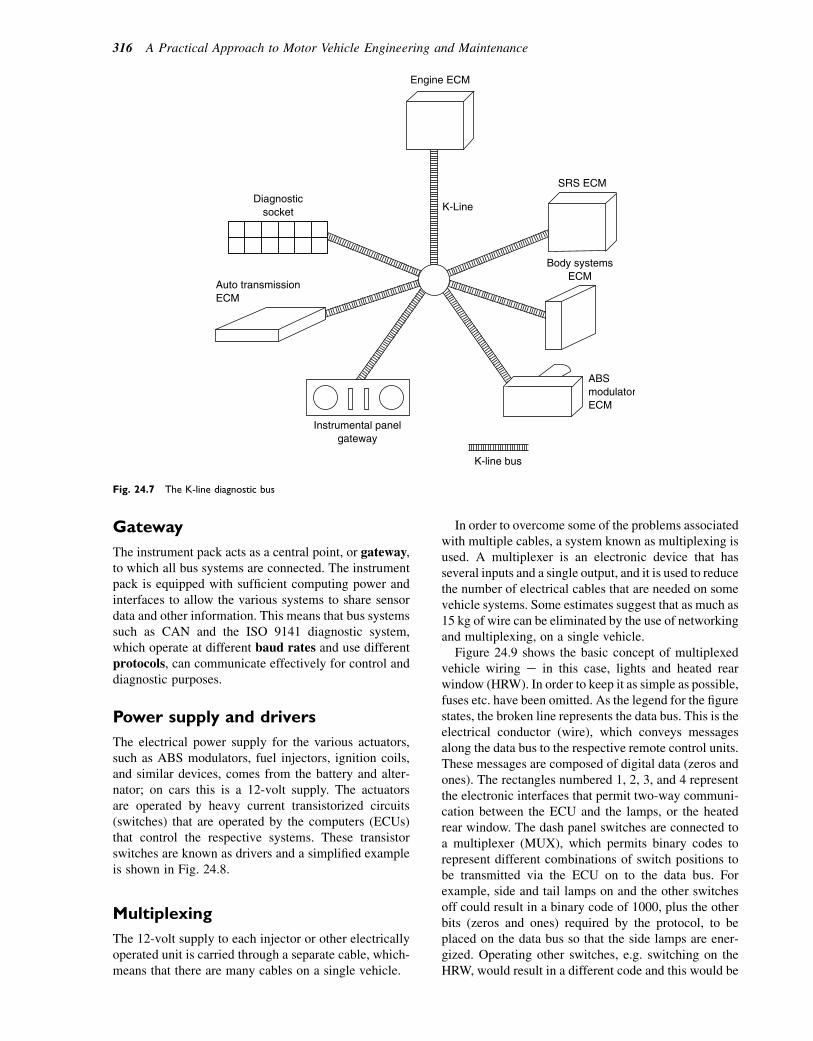
Gateway
The instrument pack acts as a central point, or gateway,to which all bus systems are connected. The instrumentpack is equipped with sufficient computing power andinterfaces to allow the various systems to share sensordata and other information. This means that bus systemssuch as CAN and the ISO 9141 diagnostic system,which operate at different baud rates and use differentprotocols, can communicate effectively for control anddiagnostic purposes.
Power supply and drivers
The electrical power supply for the various actuators,such as ABS modulators, fuel injectors, ignition coils,and similar devices, comes from the battery and alter-nator; on cars this is a 12-volt supply. The actuatorsare operated by heavy current transistorized circuits(switches) that are operated by the computers (ECUs)that control the respective systems. These transistorswitches are known as drivers and a simplified exampleis shown in Fig. 24.8.
Multiplexing
The 12-volt supply to each injector or other electricallyoperated unit is carried through a separate cable, which-means that there are many cables on a single vehicle.
In order to overcome some of the problems associatedwith multiple cables, a system known as multiplexing isused. A multiplexer is an electronic device that hasseveral inputs and a single output, and it is used to reducethe number of electrical cables that are needed on somevehicle systems. Some estimates suggest that as much as15 kg of wire can be eliminated by the use of networkingand multiplexing, on a single vehicle.
Figure 24.9 shows the basic concept of multiplexedvehicle wiring e in this case, lights and heated rearwindow (HRW). In order to keep it as simple as possible,fuses etc. have been omitted. As the legend for the figurestates, the broken line represents the data bus. This is theelectrical conductor (wire), which conveys messagesalong the data bus to the respective remote control units.These messages are composed of digital data (zeros andones). The rectangles numbered 1, 2, 3, and 4 representthe electronic interfaces that permit two-way communi-cation between the ECU and the lamps, or the heatedrear window. The dash panel switches are connected toa multiplexer (MUX), which permits binary codes torepresent different combinations of switch positions tobe transmitted via the ECU on to the data bus. Forexample, side and tail lamps on and the other switchesoff could result in a binary code of 1000, plus the otherbits (zeros and ones) required by the protocol, to beplaced on the data bus so that the side lamps are ener-gized. Operating other switches, e.g. switching on theHRW, would result in a different code and this would be
Engine ECM
SRS ECM
Body systemsECM
ABSmodulatorECM
Instrumental panelgateway
Auto transmissionECM
Diagnosticsocket K-Line
K-line bus
Fig. 24.7 The K-line diagnostic bus
316 A Practical Approach to Motor Vehicle Engineering and Maintenance
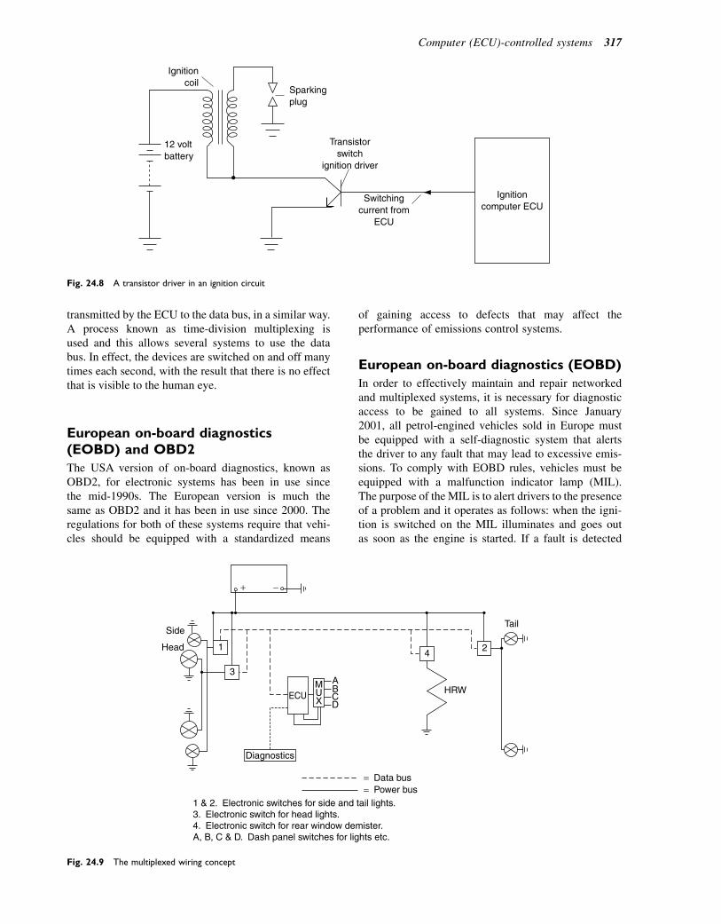
transmitted by the ECU to the data bus, in a similar way.A process known as time-division multiplexing isused and this allows several systems to use the databus. In effect, the devices are switched on and off manytimes each second, with the result that there is no effectthat is visible to the human eye.
European on-board diagnostics(EOBD) and OBD2
The USA version of on-board diagnostics, known asOBD2, for electronic systems has been in use sincethe mid-1990s. The European version is much thesame as OBD2 and it has been in use since 2000. Theregulations for both of these systems require that vehi-cles should be equipped with a standardized means
of gaining access to defects that may affect theperformance of emissions control systems.
European on-board diagnostics (EOBD)
In order to effectively maintain and repair networkedand multiplexed systems, it is necessary for diagnosticaccess to be gained to all systems. Since January2001, all petrol-engined vehicles sold in Europe mustbe equipped with a self-diagnostic system that alertsthe driver to any fault that may lead to excessive emis-sions. To comply with EOBD rules, vehicles must beequipped with a malfunction indicator lamp (MIL).The purpose of the MIL is to alert drivers to the presenceof a problem and it operates as follows: when the igni-tion is switched on the MIL illuminates and goes outas soon as the engine is started. If a fault is detected
Ignitioncoil
12 voltbattery
Sparkingplug
Switchingcurrent from
ECU
Transistorswitch
ignition driver
Ignitioncomputer ECU
Fig. 24.8 A transistor driver in an ignition circuit
+ −
3
4 2 1
Diagnostics
ECU M U X
A B C D
Side
Head
HRW
Tail
= Data bus= Power bus
1 & 2. Electronic switches for side and tail lights. 3. Electronic switch for head lights. 4. Electronic switch for rear window demister. A, B, C & D. Dash panel switches for lights etc.
Fig. 24.9 The multiplexed wiring concept
Computer (ECU)-controlled systems 317
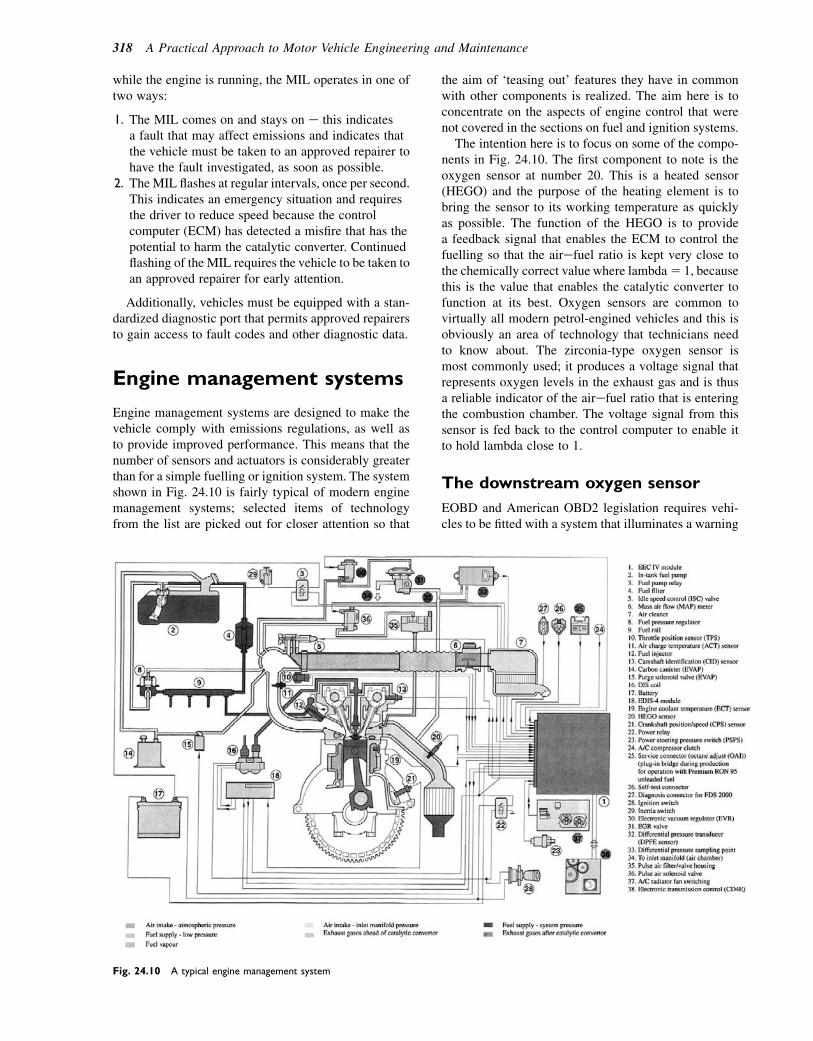
while the engine is running, the MIL operates in one oftwo ways:
1. The MIL comes on and stays on e this indicatesa fault that may affect emissions and indicates thatthe vehicle must be taken to an approved repairer tohave the fault investigated, as soon as possible.
2. TheMIL flashes at regular intervals, once per second.This indicates an emergency situation and requiresthe driver to reduce speed because the controlcomputer (ECM) has detected a misfire that has thepotential to harm the catalytic converter. Continuedflashing of the MIL requires the vehicle to be taken toan approved repairer for early attention.
Additionally, vehicles must be equipped with a stan-dardized diagnostic port that permits approved repairersto gain access to fault codes and other diagnostic data.
Engine management systems
Engine management systems are designed to make thevehicle comply with emissions regulations, as well asto provide improved performance. This means that thenumber of sensors and actuators is considerably greaterthan for a simple fuelling or ignition system. The systemshown in Fig. 24.10 is fairly typical of modern enginemanagement systems; selected items of technologyfrom the list are picked out for closer attention so that
the aim of ‘teasing out’ features they have in commonwith other components is realized. The aim here is toconcentrate on the aspects of engine control that werenot covered in the sections on fuel and ignition systems.
The intention here is to focus on some of the compo-nents in Fig. 24.10. The first component to note is theoxygen sensor at number 20. This is a heated sensor(HEGO) and the purpose of the heating element is tobring the sensor to its working temperature as quicklyas possible. The function of the HEGO is to providea feedback signal that enables the ECM to control thefuelling so that the airefuel ratio is kept very close tothe chemically correct value where lambda5 1, becausethis is the value that enables the catalytic converter tofunction at its best. Oxygen sensors are common tovirtually all modern petrol-engined vehicles and this isobviously an area of technology that technicians needto know about. The zirconia-type oxygen sensor ismost commonly used; it produces a voltage signal thatrepresents oxygen levels in the exhaust gas and is thusa reliable indicator of the airefuel ratio that is enteringthe combustion chamber. The voltage signal from thissensor is fed back to the control computer to enable itto hold lambda close to 1.
The downstream oxygen sensor
EOBD and American OBD2 legislation requires vehi-cles to be fitted with a system that illuminates a warning
Fig. 24.10 A typical engine management system
318 A Practical Approach to Motor Vehicle Engineering and Maintenance

light when an exhaust catalyst stops working properly.Feedback from the first O2 sensor is used by the ECUto adjust the amount of fuel injected so that the airefuelratio is held at about 15:1; under these conditions thecatalytic converter is able to function correctly. Thesecond O2 sensor that is shown in Fig. 24.11 samplesthe exhaust gas after it has been processed by the cata-lyst, and the ECU monitors and compares the second
sensor signal with the first; if they are the same, it istaken to mean that the catalyst is not working.
Exhaust gas recirculation
In order to reduce emissions of NOx it is helpful ifcombustion chamber temperatures do not rise aboveapproximately 18008C because this is the temperature
A
BHEGO
HEGO
Exhaust catalyst
Exhaust flange to engine
Fig. 24.11 The downstream oxygen sensor
Fig. 24.12 Exhaust gas recirculation system
Computer (ECU)-controlled systems 319
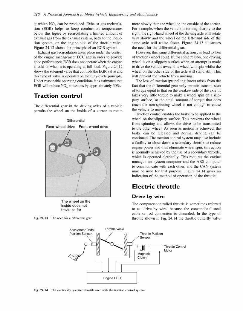
at which NOx can be produced. Exhaust gas recircula-tion (EGR) helps to keep combustion temperaturesbelow this figure by recirculating a limited amount ofexhaust gas from the exhaust system, back to the induc-tion system, on the engine side of the throttle valve.Figure 24.12 shows the principle of an EGR system.
Exhaust gas recirculation takes place under the controlof the engine management ECU and in order to providegood performance, EGR does not operate when the engineis cold or when it is operating at full load. Figure 24.12shows the solenoid valve that controls the EGR valve andthis type of valve is operated on the duty-cycle principle.Under reasonable operating conditions it is estimated thatEGR will reduce NOx emissions by approximately 30%.
Traction control
The differential gear in the driving axles of a vehiclepermits the wheel on the inside of a corner to rotate
more slowly than the wheel on the outside of the corner.For example, when the vehicle is turning sharply to theright, the right-hand wheel of the driving axle will rotatevery slowly and the wheel on the left-hand side of thesame axle will rotate faster. Figure 24.13 illustratesthe need for the differential gear.
However, this same differential action can lead to lossof traction (wheel spin). If, for some reason, one drivingwheel is on a slippery surface when an attempt is madeto drive the vehicle away, this wheel will spin whilst thewheel on the other side of the axle will stand still. Thiswill prevent the vehicle from moving.
The loss of traction (propelling force) arises from thefact that the differential gear only permits transmissionof torque equal to that on the weakest side of the axle. Ittakes very little torque to make a wheel spin on a slip-pery surface, so the small amount of torque that doesreach the non-spinning wheel is not enough to causethe vehicle to move.
Traction control enables the brake to be applied to thewheel on the slippery surface. This prevents the wheelfrom spinning and allows the drive to be transmittedto the other wheel. As soon as motion is achieved, thebrake can be released and normal driving can becontinued. The traction control system may also includea facility to close down a secondary throttle to reduceengine power and thus eliminate wheel spin; this actionis normally achieved by the use of a secondary throttle,which is operated eletrically. This requires the enginemanagement system computer and the ABS computerto communicate with each other, and the CAN systemmay be used for that purpose. Figure 24.14 gives anindication of the method of operation of the throttle.
Electric throttle
Drive by wire
The computer-controlled throttle is sometimes referredto as ‘drive by wire’ because the conventional steelcable or rod connection is discarded. In the type ofthrottle shown in Fig. 24.14 the throttle butterfly valveFig. 24.13 The need for a differential gear
Throttle Valve
Throttle PositionSensor
Throttle ControlMotor
Accelerator PedalPosition Sensor
MagneticClutch
Engine ECU
Fig. 24.14 The electrically operated throttle used with the traction control system
320 A Practical Approach to Motor Vehicle Engineering and Maintenance
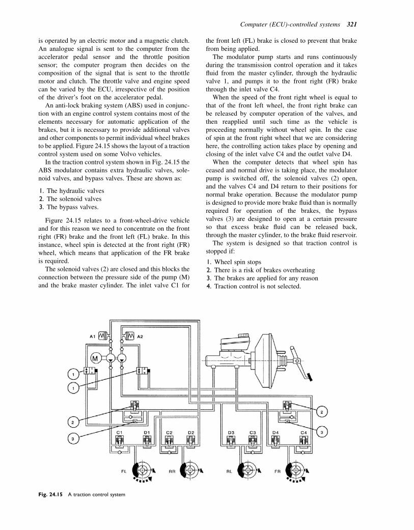
is operated by an electric motor and a magnetic clutch.An analogue signal is sent to the computer from theaccelerator pedal sensor and the throttle positionsensor; the computer program then decides on thecomposition of the signal that is sent to the throttlemotor and clutch. The throttle valve and engine speedcan be varied by the ECU, irrespective of the positionof the driver’s foot on the accelerator pedal.
An anti-lock braking system (ABS) used in conjunc-tion with an engine control system contains most of theelements necessary for automatic application of thebrakes, but it is necessary to provide additional valvesand other components to permit individual wheel brakesto be applied. Figure 24.15 shows the layout of a tractioncontrol system used on some Volvo vehicles.
In the traction control system shown in Fig. 24.15 theABS modulator contains extra hydraulic valves, sole-noid valves, and bypass valves. These are shown as:
1. The hydraulic valves2. The solenoid valves3. The bypass valves.
Figure 24.15 relates to a front-wheel-drive vehicleand for this reason we need to concentrate on the frontright (FR) brake and the front left (FL) brake. In thisinstance, wheel spin is detected at the front right (FR)wheel, which means that application of the FR brakeis required.
The solenoid valves (2) are closed and this blocks theconnection between the pressure side of the pump (M)and the brake master cylinder. The inlet valve C1 for
the front left (FL) brake is closed to prevent that brakefrom being applied.
The modulator pump starts and runs continuouslyduring the transmission control operation and it takesfluid from the master cylinder, through the hydraulicvalve 1, and pumps it to the front right (FR) brakethrough the inlet valve C4.
When the speed of the front right wheel is equal tothat of the front left wheel, the front right brake canbe released by computer operation of the valves, andthen reapplied until such time as the vehicle isproceeding normally without wheel spin. In the caseof spin at the front right wheel that we are consideringhere, the controlling action takes place by opening andclosing of the inlet valve C4 and the outlet valve D4.
When the computer detects that wheel spin hasceased and normal drive is taking place, the modulatorpump is switched off, the solenoid valves (2) open,and the valves C4 and D4 return to their positions fornormal brake operation. Because the modulator pumpis designed to provide more brake fluid than is normallyrequired for operation of the brakes, the bypassvalves (3) are designed to open at a certain pressureso that excess brake fluid can be released back,through the master cylinder, to the brake fluid reservoir.
The system is designed so that traction control isstopped if:
1. Wheel spin stops2. There is a risk of brakes overheating3. The brakes are applied for any reason4. Traction control is not selected.
Fig. 24.15 A traction control system
Computer (ECU)-controlled systems 321
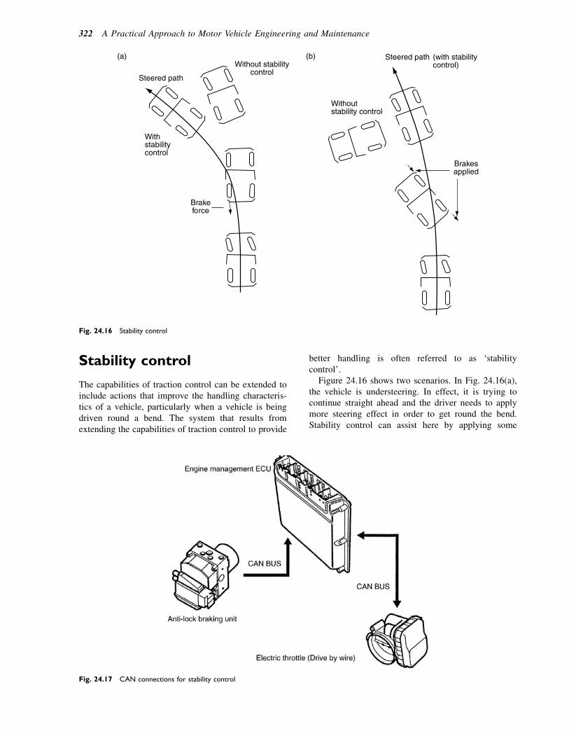
Stability control
The capabilities of traction control can be extended toinclude actions that improve the handling characteris-tics of a vehicle, particularly when a vehicle is beingdriven round a bend. The system that results fromextending the capabilities of traction control to provide
better handling is often referred to as ‘stabilitycontrol’.
Figure 24.16 shows two scenarios. In Fig. 24.16(a),the vehicle is understeering. In effect, it is trying tocontinue straight ahead and the driver needs to applymore steering effect in order to get round the bend.Stability control can assist here by applying some
Without stabilitycontrol
Withstabilitycontrol
Steered path
(a)
Brakeforce
Withoutstability control
(with stabilitycontrol)
Steered path
Brakesapplied
(b)
Fig. 24.16 Stability control
Fig. 24.17 CAN connections for stability control
322 A Practical Approach to Motor Vehicle Engineering and Maintenance
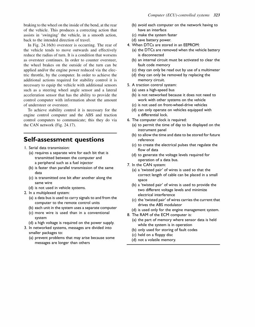
braking to the wheel on the inside of the bend, at the rearof the vehicle. This produces a correcting action thatassists in ‘swinging’ the vehicle, in a smooth action,back to the intended direction of travel.
In Fig. 24.16(b) oversteer is occurring. The rear ofthe vehicle tends to move outwards and effectivelyreduce the radius of turn. It is a condition that worsensas oversteer continues. In order to counter oversteer,the wheel brakes on the outside of the turn can beapplied and/or the engine power reduced via the elec-tric throttle, by the computer. In order to achieve theadditional actions required for stability control it isnecessary to equip the vehicle with additional sensorssuch as a steering wheel angle sensor and a lateralacceleration sensor that has the ability to provide thecontrol computer with information about the amountof understeer or oversteer.
To achieve stability control it is necessary for theengine control computer and the ABS and tractioncontrol computers to communicate; this they do viathe CAN network (Fig. 24.17).
Self-assessment questions1. Serial data transmission:
(a) requires a separate wire for each bit that istransmitted between the computer anda peripheral such as a fuel injector
(b) is faster than parallel transmission of the samedata
(c) is transmitted one bit after another along thesame wire
(d) is not used in vehicle systems.2. In a multiplexed system:
(a) a data bus is used to carry signals to and from thecomputer to the remote control units
(b) each unit in the system uses a separate computer(c) more wire is used than in a conventional
system(d) a high voltage is required on the power supply.
3. In networked systems, messages are divided intosmaller packages to:(a) prevent problems that may arise because some
messages are longer than others
(b) avoid each computer on the network having tohave an interface
(c) make the system faster(d) save battery power.
4. When DTCs are stored in an EEPROM:(a) the DTCs are removed when the vehicle battery
is disconnected(b) an internal circuit must be activated to clear the
fault code memory(c) they can only be read out by use of a multimeter(d) they can only be removed by replacing the
memory circuit.5. A traction control system:
(a) uses a high-speed bus(b) is not networked because it does not need to
work with other systems on the vehicle(c) is not used on front-wheel-drive vehicles(d) can only operate on vehicles equipped with
a differential lock.6. The computer clock is required:
(a) to permit the time of day to be displayed on theinstrument panel
(b) to allow the time and date to be stored for futurereference
(c) to create the electrical pulses that regulate theflow of data
(d) to generate the voltage levels required foroperation of a data bus.
7. In the CAN system:(a) a ‘twisted pair’ of wires is used so that the
correct length of cable can be placed in a smallspace
(b) a ‘twisted pair’ of wires is used to provide thetwo different voltage levels and minimizeelectrical interference
(c) the ‘twisted pair’ of wires carries the current thatdrives the ABS modulator
(d) is used only for the engine management system.8. The RAM of the ECM computer is:
(a) the part of memory where sensor data is heldwhile the system is in operation
(b) only used for storing of fault codes(c) held on a floppy disc(d) not a volatile memory.
Computer (ECU)-controlled systems 323
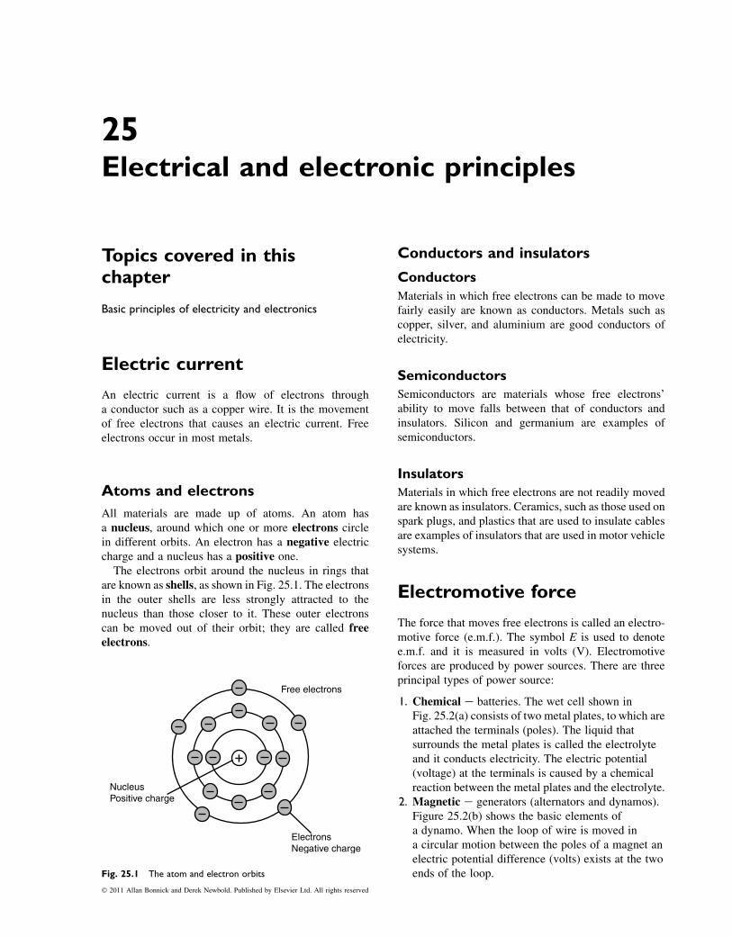
25Electrical and electronic principles
Topics covered in thischapter
Basic principles of electricity and electronics
Electric current
An electric current is a flow of electrons througha conductor such as a copper wire. It is the movementof free electrons that causes an electric current. Freeelectrons occur in most metals.
Atoms and electrons
All materials are made up of atoms. An atom hasa nucleus, around which one or more electrons circlein different orbits. An electron has a negative electriccharge and a nucleus has a positive one.
The electrons orbit around the nucleus in rings thatare known as shells, as shown in Fig. 25.1. The electronsin the outer shells are less strongly attracted to thenucleus than those closer to it. These outer electronscan be moved out of their orbit; they are called freeelectrons.
Conductors and insulators
Conductors
Materials in which free electrons can be made to movefairly easily are known as conductors. Metals such ascopper, silver, and aluminium are good conductors ofelectricity.
Semiconductors
Semiconductors are materials whose free electrons’ability to move falls between that of conductors andinsulators. Silicon and germanium are examples ofsemiconductors.
Insulators
Materials in which free electrons are not readily movedare known as insulators. Ceramics, such as those used onspark plugs, and plastics that are used to insulate cablesare examples of insulators that are used in motor vehiclesystems.
Electromotive force
The force that moves free electrons is called an electro-motive force (e.m.f.). The symbol E is used to denotee.m.f. and it is measured in volts (V). Electromotiveforces are produced by power sources. There are threeprincipal types of power source:
1. Chemical e batteries. The wet cell shown inFig. 25.2(a) consists of two metal plates, to which areattached the terminals (poles). The liquid thatsurrounds the metal plates is called the electrolyteand it conducts electricity. The electric potential(voltage) at the terminals is caused by a chemicalreaction between the metal plates and the electrolyte.
2. Magnetic e generators (alternators and dynamos).Figure 25.2(b) shows the basic elements ofa dynamo. When the loop of wire is moved ina circular motion between the poles of a magnet anelectric potential difference (volts) exists at the twoends of the loop.
Free electrons
NucleusPositive charge
ElectronsNegative charge
Fig. 25.1 The atom and electron orbits
� 2011 Allan Bonnick and Derek Newbold. Published by Elsevier Ltd. All rights reserved
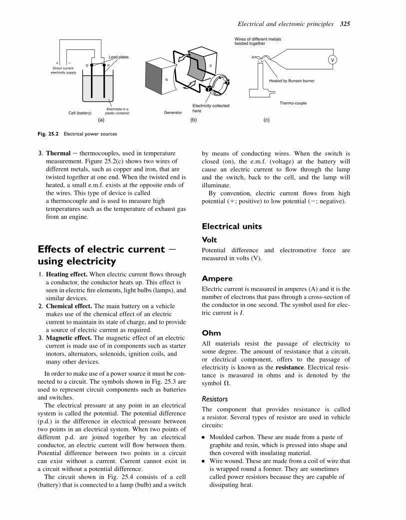
3. Thermal e thermocouples, used in temperaturemeasurement. Figure 25.2(c) shows two wires ofdifferent metals, such as copper and iron, that aretwisted together at one end. When the twisted end isheated, a small e.m.f. exists at the opposite ends ofthe wires. This type of device is calleda thermocouple and is used to measure hightemperatures such as the temperature of exhaust gasfrom an engine.
Effects of electric current eusing electricity1. Heating effect. When electric current flows through
a conductor, the conductor heats up. This effect isseen in electric fire elements, light bulbs (lamps), andsimilar devices.
2. Chemical effect. The main battery on a vehiclemakes use of the chemical effect of an electriccurrent to maintain its state of charge, and to providea source of electric current as required.
3. Magnetic effect. The magnetic effect of an electriccurrent is made use of in components such as startermotors, alternators, solenoids, ignition coils, andmany other devices.
In order to make use of a power source it must be con-nected to a circuit. The symbols shown in Fig. 25.3 areused to represent circuit components such as batteriesand switches.
The electrical pressure at any point in an electricalsystem is called the potential. The potential difference(p.d.) is the difference in electrical pressure betweentwo points in an electrical system. When two points ofdifferent p.d. are joined together by an electricalconductor, an electric current will flow between them.Potential difference between two points in a circuitcan exist without a current. Current cannot exist ina circuit without a potential difference.
The circuit shown in Fig. 25.4 consists of a cell(battery) that is connected to a lamp (bulb) and a switch
by means of conducting wires. When the switch isclosed (on), the e.m.f. (voltage) at the battery willcause an electric current to flow through the lampand the switch, back to the cell, and the lamp willilluminate.
By convention, electric current flows from highpotential (1; positive) to low potential (2; negative).
Electrical units
Volt
Potential difference and electromotive force aremeasured in volts (V).
Ampere
Electric current is measured in amperes (A) and it is thenumber of electrons that pass through a cross-section ofthe conductor in one second. The symbol used for elec-tric current is I.
Ohm
All materials resist the passage of electricity tosome degree. The amount of resistance that a circuit,or electrical component, offers to the passage ofelectricity is known as the resistance. Electrical resis-tance is measured in ohms and is denoted by thesymbol V.
Resistors
The component that provides resistance is calleda resistor. Several types of resistor are used in vehiclecircuits:
� Moulded carbon. These are made from a paste ofgraphite and resin, which is pressed into shape andthen covered with insulating material.
� Wire wound. These are made from a coil of wire thatis wrapped round a former. They are sometimescalled power resistors because they are capable ofdissipating heat.
+ –Direct current
electricity supply
Lead plates
Q P
Cell (battery)Electrolyte in a
plastic container
(a) (b)
N
S
Generator
Electricity collectedhere
V
Wires of different metalstwisted together
(c)
Heated by Bunsen burner
Thermo-couple
Fig. 25.2 Electrical power sources
Electrical and electronic principles 325

� Carbon film. These are made by evaporating a thinlayer of carbon on to a ceramic insulator.
� Metal film. These are made by evaporating a thinlayer of metal on to a ceramic former.
The coloured bands on the resistor (Fig. 25.5) repre-sent the resistance value in ohms. The first two bandsgive the first two digits of the number. The third bandgives the power of 10 by which the first number
is multiplied. The fourth band is the tolerance (seeTable 25.1).
A resistor with the following bands:
1. Red2. Red3. Orange4. Brown
has a resistance of 22 3 103 5 22 000 6 220 V.
Name of device
Electric cell
Diode
Lamp (bulb)
Transistor (npn)
Switch
Conductors (wires)joining
Zener diode
Light dependentresistor (LDR)
Conductors (wires)crossing
Light emitting diode(LED)
Battery
Resistor
Variable resistor
Potentiometer
Inductor (coil)
Capacitor
Transformer
Fuse
Name of deviceSymbol Symbol
Fig. 25.3 Circuit symbols
Lamp
Wire conductor
Switch
Battery
+ –
+ to −Current flow
Fig. 25.4 Simple circuit
1 2 3 4
Coloured rings
Fig. 25.5 Colour coding of resistors
326 A Practical Approach to Motor Vehicle Engineering and Maintenance
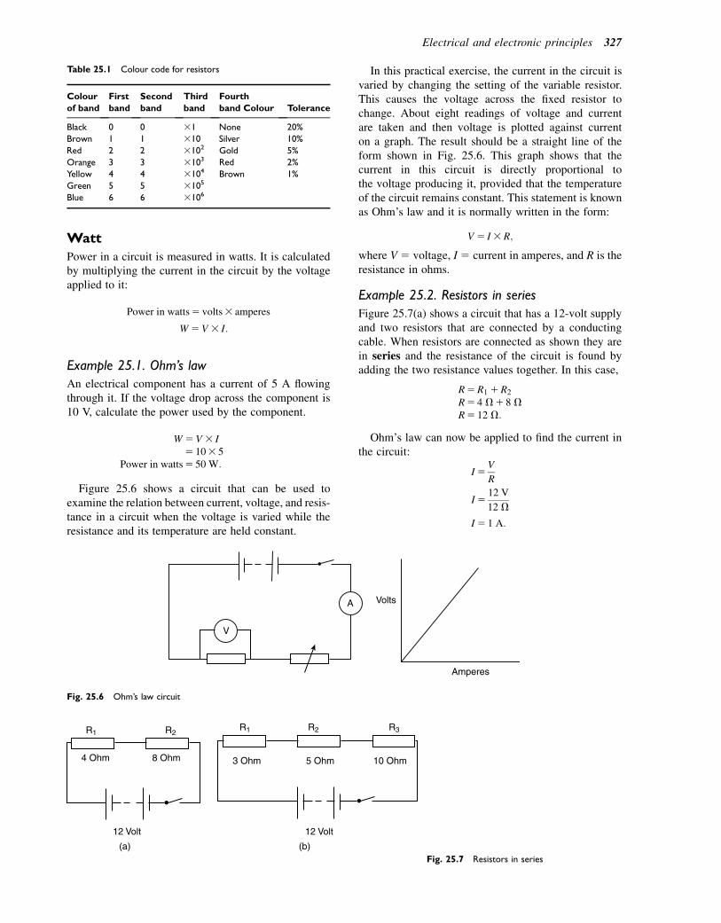
Watt
Power in a circuit is measured in watts. It is calculatedby multiplying the current in the circuit by the voltageapplied to it:
Power in watts5 volts3 amperes
W5V 3 I:
Example 25.1. Ohm’s law
An electrical component has a current of 5 A flowingthrough it. If the voltage drop across the component is10 V, calculate the power used by the component.
W 5V3 I5 103 5
Power in watts5 50 W:
Figure 25.6 shows a circuit that can be used toexamine the relation between current, voltage, and resis-tance in a circuit when the voltage is varied while theresistance and its temperature are held constant.
In this practical exercise, the current in the circuit isvaried by changing the setting of the variable resistor.This causes the voltage across the fixed resistor tochange. About eight readings of voltage and currentare taken and then voltage is plotted against currenton a graph. The result should be a straight line of theform shown in Fig. 25.6. This graph shows that thecurrent in this circuit is directly proportional tothe voltage producing it, provided that the temperatureof the circuit remains constant. This statement is knownas Ohm’s law and it is normally written in the form:
V5 I3R;
where V5 voltage, I5 current in amperes, and R is theresistance in ohms.
Example 25.2. Resistors in series
Figure 25.7(a) shows a circuit that has a 12-volt supplyand two resistors that are connected by a conductingcable. When resistors are connected as shown they arein series and the resistance of the circuit is found byadding the two resistance values together. In this case,
R5R1 1R2
R5 4 V1 8 VR5 12 V:
Ohm’s law can now be applied to find the current inthe circuit:
I5V
R
I512 V
12 V
I5 1 A:
Table 25.1 Colour code for resistors
Colour
of band
First
band
Second
band
Third
band
Fourth
band Colour Tolerance
Black 0 0 31 None 20%
Brown 1 1 310 Silver 10%
Red 2 2 3102 Gold 5%
Orange 3 3 3103 Red 2%
Yellow 4 4 3104 Brown 1%
Green 5 5 3105
Blue 6 6 3106
A
V
Volts
Amperes
Fig. 25.6 Ohm’s law circuit
R1 R2R1 R2 R3
4 Ohm 8 Ohm 3 Ohm 5 Ohm 10 Ohm
12 Volt 12 Volt
(a) (b)Fig. 25.7 Resistors in series
Electrical and electronic principles 327

In Fig. 25.7(b), the total resistance is given by:
R5R1 1R2 1R3
R5 3 V1 5 V1 10 VR5 18 V:
The current in this case is:
I5V
R
I512
18
I5 0:67 A:
In a series circuit the current is the same in all parts ofthe circuit.
Example 25.3. Resistors in parallel
Figure 25.8 shows a circuit in which two resistors areplaced in parallel. This ensures that the same p.d.(voltage) is applied to each resistor. Ohm’s law can beused to find the current in each resistor as follows:
For resistor R1; I5V
R1
512
6I1 5 2 A:
For resistor R2; I5V
R2
512
4I25 3 A:
The total current drawn from the supply is:
I5 I1 1 I2 5 21 35 5 A:
There is an alternative method of finding total currentin a circuit containing resistors in parallel. The equiva-lent series resistance of the resistors in parallel can befound as follows:
Let R 5 the equivalent series resistance, then:
1
R5
1
R11
1
R2:
Using the rules for fractions, the equivalent seriesresistance is:
R5R1R2
R11R2:
Example 25.4
The circuit in Fig. 25.8 has the two resistors, R1 5 6 Vand R2 5 4 V, in parallel. Using the equation for theequivalent series resistance:
R563 4
61 4
524
10
R5 2:4 V:
To find the current in the circuit:
I5V
R
512
2:4
I5 5 A:
Measuring current andvoltage
See Fig. 25.9. The ammeter measures the current and itis connected in series so that all of the current in thecircuit flows through it. The voltmeter is connected inparallel and it measures the potential differencebetween the two points to which it is connected. Thep.d. between two points is sometimes referred to asthe voltage drop.
Ohmmeter
An ohmmeter is essentially an ammeter that has beenadapted to measure resistance (see Fig. 25.10). Theohmmeter operates by applying a small voltage bymeans of a battery incorporated into the meter. Thecurrent flowing is then recorded on a scale that iscalibrated in ohms (V).
R1 = 6Ω
R2 = 4Ω
12V+ –
Fig. 25.8 Resistors in parallel
V
A
CurrentFlow
Fig. 25.9 Ammeter and voltmeter connected to a circuit
328 A Practical Approach to Motor Vehicle Engineering and Maintenance
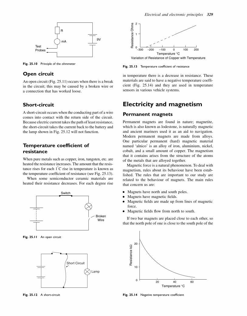
Open circuit
An open circuit (Fig. 25.11) occurs when there is a breakin the circuit; this may be caused by a broken wire ora connection that has worked loose.
Short-circuit
A short-circuit occurs when the conducting part of a wirecomes into contact with the return side of the circuit.Because electric current takes the path of least resistance,the short-circuit takes the current back to the battery andthe lamp shown in Fig. 25.12 will not function.
Temperature coefficient ofresistance
When pure metals such as copper, iron, tungsten, etc. areheated the resistance increases. The amount that the resis-tance rises for each 18C rise in temperature is known asthe temperature coefficient of resistance (see Fig. 25.13).
When some semiconductor ceramic materials areheated their resistance decreases. For each degree rise
in temperature there is a decrease in resistance. Thesematerials are said to have a negative temperature coeffi-cient (Fig. 25.14) and they are used in temperaturesensors in various vehicle systems.
Electricity and magnetism
Permanent magnets
Permanent magnets are found in nature; magnetite,which is also known as lodestone, is naturally magneticand ancient mariners used it as an aid to navigation.Modern permanent magnets are made from alloys.One particular permanent (hard) magnetic materialnamed ‘alnico’ is an alloy of iron, aluminium, nickel,cobalt, and a small amount of copper. The magnetismthat it contains arises from the structure of the atomsof the metals that are alloyed together.
Magnetic force is a natural phenomenon. To deal withmagnetism, rules about its behaviour have been estab-lished. The rules that are important to our study arerelated to the behaviour of magnets. The main rulesthat concern us are:
� Magnets have north and south poles.� Magnets have magnetic fields.� Magnetic fields are made up from lines of magnetic
force.� Magnetic fields flow from north to south.
If two bar magnets are placed close to each other, sothat the north pole of one is close to the south pole of the
BrokenWire
Switch
Fig. 25.11 An open circuit
Short Circuit
Lamp
Fig. 25.12 A short-circuit
Res
ista
nce
Ohm
s
Temperature °CVariation of Resistance of Copper with Temperature
–3000
1
2
–200 –100 0 100 200
Fig. 25.13 Temperature coefficient of resistance
Res
ista
nce
kΩ
Temperature °C
10
20
020 40 60
Fig. 25.14 Negative temperature coefficient
R
mA9V
TestProbes
Fig. 25.10 Principle of the ohmmeter
Electrical and electronic principles 329
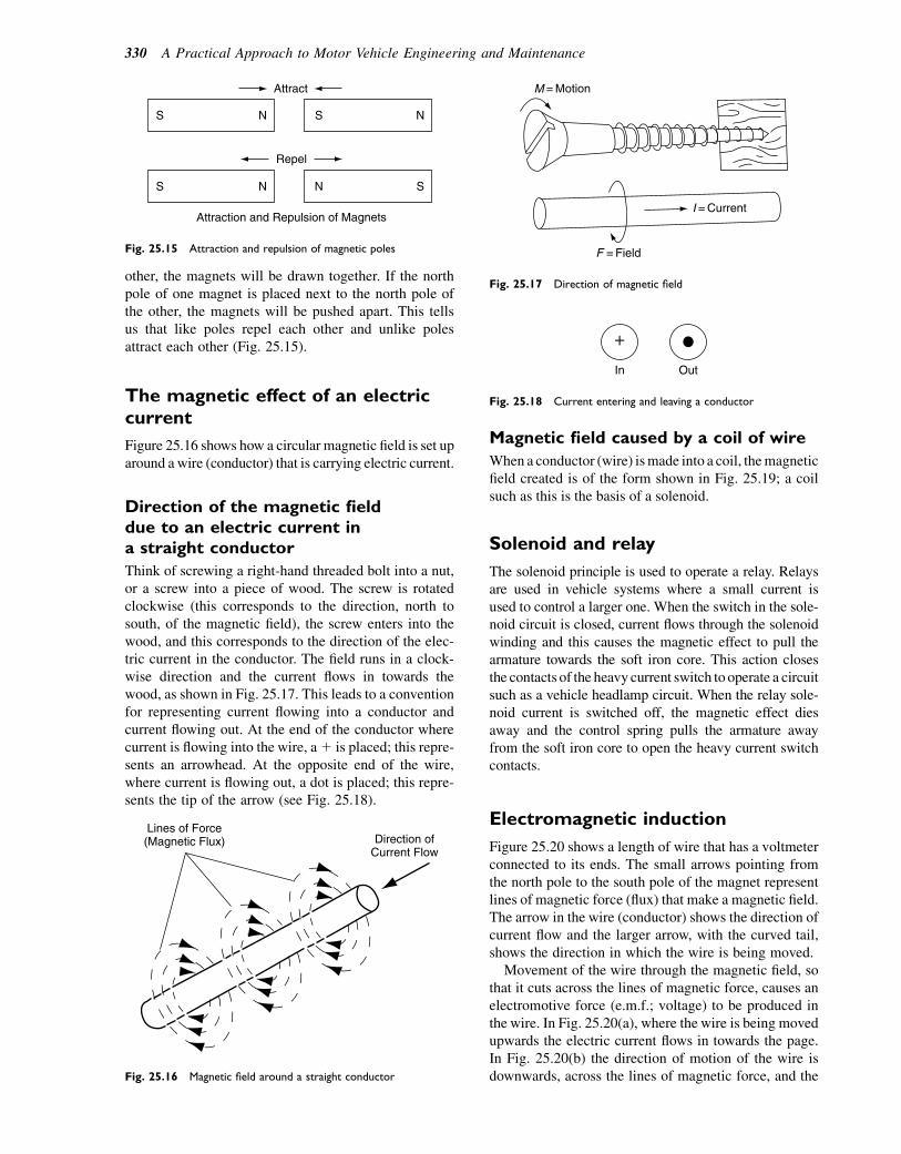
other, the magnets will be drawn together. If the northpole of one magnet is placed next to the north pole ofthe other, the magnets will be pushed apart. This tellsus that like poles repel each other and unlike polesattract each other (Fig. 25.15).
The magnetic effect of an electriccurrent
Figure 25.16 shows how a circular magnetic field is set uparound a wire (conductor) that is carrying electric current.
Direction of the magnetic fielddue to an electric current ina straight conductor
Think of screwing a right-hand threaded bolt into a nut,or a screw into a piece of wood. The screw is rotatedclockwise (this corresponds to the direction, north tosouth, of the magnetic field), the screw enters into thewood, and this corresponds to the direction of the elec-tric current in the conductor. The field runs in a clock-wise direction and the current flows in towards thewood, as shown in Fig. 25.17. This leads to a conventionfor representing current flowing into a conductor andcurrent flowing out. At the end of the conductor wherecurrent is flowing into the wire, a1 is placed; this repre-sents an arrowhead. At the opposite end of the wire,where current is flowing out, a dot is placed; this repre-sents the tip of the arrow (see Fig. 25.18).
Magnetic field caused by a coil of wire
When a conductor (wire) ismade into a coil, themagneticfield created is of the form shown in Fig. 25.19; a coilsuch as this is the basis of a solenoid.
Solenoid and relay
The solenoid principle is used to operate a relay. Relaysare used in vehicle systems where a small current isused to control a larger one. When the switch in the sole-noid circuit is closed, current flows through the solenoidwinding and this causes the magnetic effect to pull thearmature towards the soft iron core. This action closesthe contacts of the heavy current switch to operate a circuitsuch as a vehicle headlamp circuit. When the relay sole-noid current is switched off, the magnetic effect diesaway and the control spring pulls the armature awayfrom the soft iron core to open the heavy current switchcontacts.
Electromagnetic induction
Figure 25.20 shows a length of wire that has a voltmeterconnected to its ends. The small arrows pointing fromthe north pole to the south pole of the magnet representlines of magnetic force (flux) that make a magnetic field.The arrow in the wire (conductor) shows the direction ofcurrent flow and the larger arrow, with the curved tail,shows the direction in which the wire is being moved.
Movement of the wire through the magnetic field, sothat it cuts across the lines of magnetic force, causes anelectromotive force (e.m.f.; voltage) to be produced inthe wire. In Fig. 25.20(a), where the wire is being movedupwards the electric current flows in towards the page.In Fig. 25.20(b) the direction of motion of the wire isdownwards, across the lines of magnetic force, and the
Attract
S N
S N
S N
SN
Repel
Attraction and Repulsion of Magnets
Fig. 25.15 Attraction and repulsion of magnetic poles
Lines of Force(Magnetic Flux) Direction of
Current Flow
Fig. 25.16 Magnetic field around a straight conductor
F = Field
I = Current
M = Motion
Fig. 25.17 Direction of magnetic field
+
In Out
Fig. 25.18 Current entering and leaving a conductor
330 A Practical Approach to Motor Vehicle Engineering and Maintenance
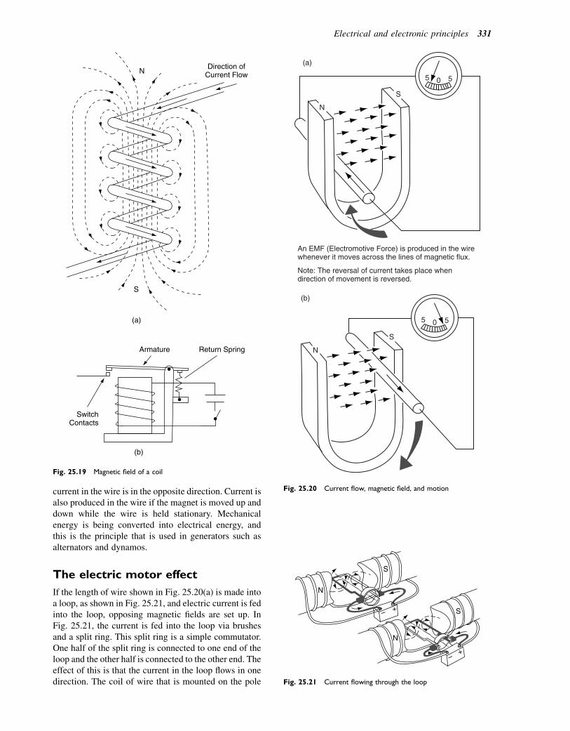
current in the wire is in the opposite direction. Current isalso produced in the wire if the magnet is moved up anddown while the wire is held stationary. Mechanicalenergy is being converted into electrical energy, andthis is the principle that is used in generators such asalternators and dynamos.
The electric motor effect
If the length of wire shown in Fig. 25.20(a) is made intoa loop, as shown in Fig. 25.21, and electric current is fedinto the loop, opposing magnetic fields are set up. InFig. 25.21, the current is fed into the loop via brushesand a split ring. This split ring is a simple commutator.One half of the split ring is connected to one end of theloop and the other half is connected to the other end. Theeffect of this is that the current in the loop flows in onedirection. The coil of wire that is mounted on the pole
Direction ofCurrent FlowN
S
(a)
(b)
SwitchContacts
Armature Return Spring
Fig. 25.19 Magnetic field of a coil
S
5 5 0
N
(a)
An EMF (Electromotive Force) is produced in the wirewhenever it moves across the lines of magnetic flux.
Note: The reversal of current takes place whendirection of movement is reversed.
S
(b)
5 5 0
N
Fig. 25.20 Current flow, magnetic field, and motion
S
N
N
S+–
+–
Fig. 25.21 Current flowing through the loop
Electrical and electronic principles 331
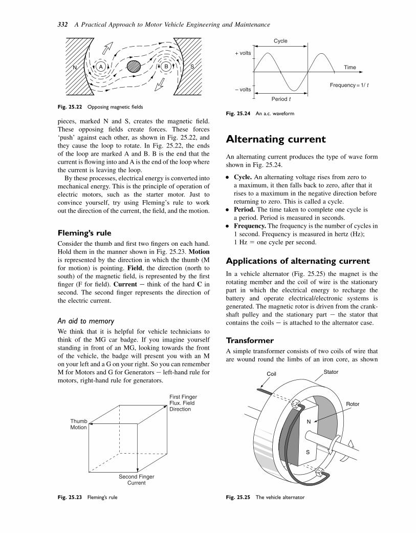
pieces, marked N and S, creates the magnetic field.These opposing fields create forces. These forces‘push’ against each other, as shown in Fig. 25.22, andthey cause the loop to rotate. In Fig. 25.22, the endsof the loop are marked A and B. B is the end that thecurrent is flowing into and A is the end of the loop wherethe current is leaving the loop.
By these processes, electrical energy is converted intomechanical energy. This is the principle of operation ofelectric motors, such as the starter motor. Just toconvince yourself, try using Fleming’s rule to workout the direction of the current, the field, and the motion.
Fleming’s rule
Consider the thumb and first two fingers on each hand.Hold them in the manner shown in Fig. 25.23. Motionis represented by the direction in which the thumb (Mfor motion) is pointing. Field, the direction (north tosouth) of the magnetic field, is represented by the firstfinger (F for field). Current e think of the hard C insecond. The second finger represents the direction ofthe electric current.
An aid to memory
We think that it is helpful for vehicle technicians tothink of the MG car badge. If you imagine yourselfstanding in front of an MG, looking towards the frontof the vehicle, the badge will present you with an Mon your left and a G on your right. So you can rememberM for Motors and G for Generators e left-hand rule formotors, right-hand rule for generators.
Alternating current
An alternating current produces the type of wave formshown in Fig. 25.24.
� Cycle. An alternating voltage rises from zero toa maximum, it then falls back to zero, after that itrises to a maximum in the negative direction beforereturning to zero. This is called a cycle.
� Period. The time taken to complete one cycle isa period. Period is measured in seconds.
� Frequency. The frequency is the number of cycles in1 second. Frequency is measured in hertz (Hz);1 Hz 5 one cycle per second.
Applications of alternating current
In a vehicle alternator (Fig. 25.25) the magnet is therotating member and the coil of wire is the stationarypart in which the electrical energy to recharge thebattery and operate electrical/electronic systems isgenerated. The magnetic rotor is driven from the crank-shaft pulley and the stationary part e the stator thatcontains the coils e is attached to the alternator case.
Transformer
A simple transformer consists of two coils of wire thatare wound round the limbs of an iron core, as shown
N SA B
Fig. 25.22 Opposing magnetic fields
First FingerFlux. Field Direction
Second Finger Current
Thumb Motion
Fig. 25.23 Fleming’s rule
Cycle
Period t
Time
Frequency = 1/ t– volts
+ volts
Fig. 25.24 An a.c. waveform
N
S
Coil Stator
Rotor
Fig. 25.25 The vehicle alternator
332 A Practical Approach to Motor Vehicle Engineering and Maintenance
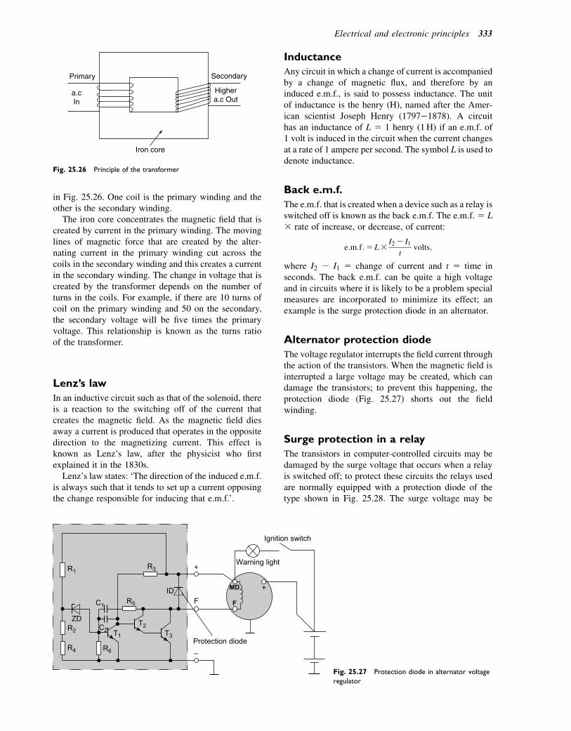
in Fig. 25.26. One coil is the primary winding and theother is the secondary winding.
The iron core concentrates the magnetic field that iscreated by current in the primary winding. The movinglines of magnetic force that are created by the alter-nating current in the primary winding cut across thecoils in the secondary winding and this creates a currentin the secondary winding. The change in voltage that iscreated by the transformer depends on the number ofturns in the coils. For example, if there are 10 turns ofcoil on the primary winding and 50 on the secondary,the secondary voltage will be five times the primaryvoltage. This relationship is known as the turns ratioof the transformer.
Lenz’s law
In an inductive circuit such as that of the solenoid, thereis a reaction to the switching off of the current thatcreates the magnetic field. As the magnetic field diesaway a current is produced that operates in the oppositedirection to the magnetizing current. This effect isknown as Lenz’s law, after the physicist who firstexplained it in the 1830s.
Lenz’s law states: ‘The direction of the induced e.m.f.is always such that it tends to set up a current opposingthe change responsible for inducing that e.m.f.’.
Inductance
Any circuit in which a change of current is accompaniedby a change of magnetic flux, and therefore by aninduced e.m.f., is said to possess inductance. The unitof inductance is the henry (H), named after the Amer-ican scientist Joseph Henry (1797e1878). A circuithas an inductance of L 5 1 henry (1H) if an e.m.f. of1 volt is induced in the circuit when the current changesat a rate of 1 ampere per second. The symbol L is used todenote inductance.
Back e.m.f.
The e.m.f. that is created when a device such as a relay isswitched off is known as the back e.m.f. The e.m.f. 5 L3 rate of increase, or decrease, of current:
e:m:f:5 L3I2 2 I1
tvolts;
where I2 2 I1 5 change of current and t 5 time inseconds. The back e.m.f. can be quite a high voltageand in circuits where it is likely to be a problem specialmeasures are incorporated to minimize its effect; anexample is the surge protection diode in an alternator.
Alternator protection diode
The voltage regulator interrupts the field current throughthe action of the transistors. When the magnetic field isinterrupted a large voltage may be created, which candamage the transistors; to prevent this happening, theprotection diode (Fig. 25.27) shorts out the fieldwinding.
Surge protection in a relay
The transistors in computer-controlled circuits may bedamaged by the surge voltage that occurs when a relayis switched off; to protect these circuits the relays usedare normally equipped with a protection diode of thetype shown in Fig. 25.28. The surge voltage may be
Primary
a.cIn
Secondary
Highera.c Out
Iron core
Fig. 25.26 Principle of the transformer
R1R3
T3
T2
+
T1
C1
C2
FF
Protection diode
Warning light
Ignition switch
+
ZD
MDID
–
R5
R2
R4 R6
Fig. 25.27 Protection diode in alternator voltage
regulator
Electrical and electronic principles 333

100 volts or so and the diode directs the current back tothe relay coil, where it oscillates until its energy isdissipated.
Inductive reactance
Figure 25.29(a) shows that when the switch is on, therising current causes the coil (inductor) to producea current that opposes the battery current. InFig. 25.29(b) the switch is off and the battery currentis falling. The current from the inductor keeps a currentflowing in the direction of the original battery current.In an a.c. circuit this effect gives rise to inductivereactance that has the same effect as resistance. Induc-tive reactance is measured in ohms:
Inductive reactance Xl5 2pfL;
where f 5 frequency and L 5 inductance in henries.
Time constant for an inductive circuit
Figure 25.29(c) shows how the current grows from zeroto its maximum value when the switch is on. The time
taken for the current to reach two-thirds of its maximumvalue is known as the time constant:
Time constant t5L
Rseconds;
where L 5 inductance in henries and R 5 resistance inohms.
Example 25.5
A circuit containing a coil having an inductance of 2 His connected in series with a resistance of 4V. Calculatethe time constant for the circuit.
Time constant t5L
R52
45 0:5 seconds:
Capacitors
A capacitor is a device that acts as a temporary store ofelectricity. In its simplest form a capacitor consists oftwo parallel metal plates separated by a material calleda dielectric. The external leads are connected to the twometal plates as shown in Fig. 25.30.
When a voltage is applied to the capacitor electronsare stored on one plate and removed from the other, inequal quantities, until the voltage is the same as thatof the supply. The action sets up a potential differencethat remains when the external voltage is removed.The capacitor will store an electric charge until it is con-nected to a circuit; when it discharges into it the voltagemay be considerably higher than the charging voltage.The ability of a capacitor to store electricity is calledits capacitance. Capacitance is measured in farads afterMichael Faraday, who worked in London in thenineteenth century.
Capacitance
Capacitance is determined by the properties of thedielectric and the dimensions of the metal plates. It iscalculated from the formula:
C5303rA
dfarads:
Relay coil
Protection diode
Fig. 25.28 Surge protection diode in a relay
Switch On
(a) (b) (c)
R
L
Switch Off
R
L
Max Current
Cur
rent
Time
Max Current 2 3
Fig. 25.29 Inductive reactance
334 A Practical Approach to Motor Vehicle Engineering and Maintenance

The terms 30 and 3r are properties of a dielectric andthey are called permittivity. A is the area of the plates inmm2 and d is the distance between them in mm. A faradis a very large unit of capacitance and capacitors are nor-mally rated in microfarads, mF.
Capacitance in a circuit
Figure 25.31(a) shows a circuit that can be used toexamine the charging of a capacitor. When the switchis closed, the capacitor is discharged. When the switchis opened, the capacitor will recharge. The voltmeter isobservedwhilst the time is recorded. The result is plottedand a graph of the type shown in Fig. 25.31(b) isproduced. This graph shows how the capacitor voltagechanges with time. The time taken for the capacitor toreach two-thirds of the supply voltage is known as thetime constant for the circuit:
Time constant T5R3C seconds;
where R 5 resistance in ohms and C 5 capacitance infarads. Capacitance values are normally given inmillionths of a farad known as microfarads and denotedby the symbol mF.
Capacitors have the ability to block direct current andpass alternating current.
Example 25.6
A circuit of the type shown in Fig. 25.31(a) has resis-tance of 10 000 V and a capacitance of 10 000 mF.Calculate the time constant for the circuit.
Time constant T 5C3R5 0:013 10 0005 100 seconds:
Capacitors in circuits
Contact breaker-type ignition
In the contact breaker-type ignition system, a capacitoris placed in parallel with the contact breaker(Fig. 25.32). When the contact points open, a self-induced high-voltage electric charge attempts to arcacross the points. The capacitor overcomes this problemby storing the electric charge until the points gap is largeenough to prevent arcing.
Capacitive discharge
In the capacitive discharge ignition system (Fig. 25.33)the capacitor stores electrical energy until a spark isrequired. When a spark is required an electronic circuitreleases the energy from the capacitor into the ignitioncoil circuit to produce a high-voltage spark at thesparking plug.
Capacitors connected in parallel
Figure 25.34(a) shows two capacitors connected inparallel. The total capacitance provided by the twocapacitors 5 C 5 C1 1 C2. Figure 25.34(b) shows thetwo capacitors connected in series. In this case the totalcapacitance is:
C5C1C2
C1 1C2:
+Metal plate
Battery
PolymerPolymer Ceramic
Ceramic Ceramic Ceramic
Metal plate
Dielectric
Switch
–
Fig. 25.30 Capacitors
Electrical and electronic principles 335
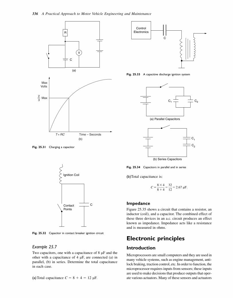
Example 25.7
Two capacitors, one with a capacitance of 8 mF and theother with a capacitance of 4 mF, are connected (a) inparallel, (b) in series. Determine the total capacitancein each case.
(a)Total capacitance C 5 8 1 4 5 12 mF.
(b)Total capacitance is:
C583 4
81 45
32
125 2:67 mF:
Impedance
Figure 25.35 shows a circuit that contains a resistor, aninductor (coil), and a capacitor. The combined effect ofthese three devices in an a.c. circuit produces an effectknown as impedance. Impedance acts like a resistanceand is measured in ohms.
Electronic principles
Introduction
Microprocessors are small computers and they are used inmany vehicle systems, such as engine management, anti-lock braking, traction control, etc. In order to function, themicroprocessor requires inputs from sensors; these inputsare used to make decisions that produce outputs that oper-ate various actuators. Many of these sensors and actuators
ContactPoints
C
Ignition Coil
Fig. 25.32 Capacitor in contact breaker ignition circuit
C
V
R
(a)
(b)
T = RC Time – Seconds
Max Volts
Max 2 3
Fig. 25.31 Charging a capacitor
C
ControlElectronics
Fig. 25.33 A capacitive discharge ignition system
C1 C2
(a) Parallel Capacitors
C1
C2
(b) Series Capacitors
Fig. 25.34 Capacitors in parallel and in series
336 A Practical Approach to Motor Vehicle Engineering and Maintenance
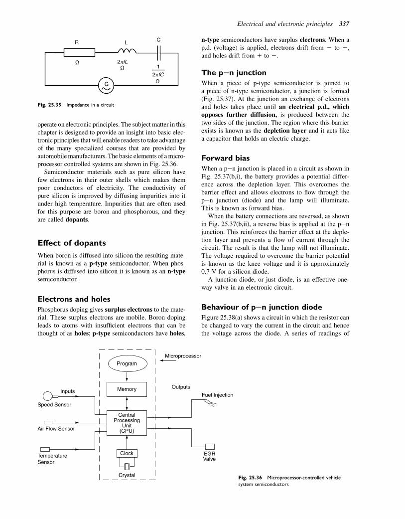
operate on electronic principles. The subject matter in thischapter is designed to provide an insight into basic elec-tronic principles that will enable readers to take advantageof the many specialized courses that are provided byautomobilemanufacturers. The basic elements of amicro-processor controlled systems are shown in Fig. 25.36.
Semiconductor materials such as pure silicon havefew electrons in their outer shells which makes thempoor conductors of electricity. The conductivity ofpure silicon is improved by diffusing impurities into itunder high temperature. Impurities that are often usedfor this purpose are boron and phosphorous, and theyare called dopants.
Effect of dopants
When boron is diffused into silicon the resulting mate-rial is known as a p-type semiconductor. When phos-phorus is diffused into silicon it is known as an n-typesemiconductor.
Electrons and holes
Phosphorus doping gives surplus electrons to the mate-rial. These surplus electrons are mobile. Boron dopingleads to atoms with insufficient electrons that can bethought of as holes; p-type semiconductors have holes,
n-type semiconductors have surplus electrons. When ap.d. (voltage) is applied, electrons drift from 2 to 1,and holes drift from 1 to 2.
The pen junction
When a piece of p-type semiconductor is joined toa piece of n-type semiconductor, a junction is formed(Fig. 25.37). At the junction an exchange of electronsand holes takes place until an electrical p.d., whichopposes further diffusion, is produced between thetwo sides of the junction. The region where this barrierexists is known as the depletion layer and it acts likea capacitor that holds an electric charge.
Forward bias
When a pen junction is placed in a circuit as shown inFig. 25.37(b,i), the battery provides a potential differ-ence across the depletion layer. This overcomes thebarrier effect and allows electrons to flow through thepen junction (diode) and the lamp will illuminate.This is known as forward bias.
When the battery connections are reversed, as shownin Fig. 25.37(b,ii), a reverse bias is applied at the penjunction. This reinforces the barrier effect at the deple-tion layer and prevents a flow of current through thecircuit. The result is that the lamp will not illuminate.The voltage required to overcome the barrier potentialis known as the knee voltage and it is approximately0.7 V for a silicon diode.
A junction diode, or just diode, is an effective one-way valve in an electronic circuit.
Behaviour of pen junction diode
Figure 25.38(a) shows a circuit in which the resistor canbe changed to vary the current in the circuit and hencethe voltage across the diode. A series of readings of
L
2πfC
CR
G
2πfL1
Fig. 25.35 Impedance in a circuit
Inputs
Speed Sensor
Air Flow Sensor
TemperatureSensor
Crystal
Clock
CentralProcessing
Unit(CPU)
Memory
ProgramMicroprocessor
Outputs
Fuel Injection
EGRValve
Fig. 25.36 Microprocessor-controlled vehicle
system semiconductors
Electrical and electronic principles 337
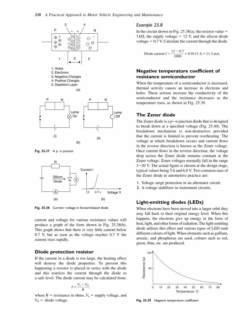
current and voltage for various resistance values willproduce a graph of the form shown in Fig. 25.38(b).This graph shows that there is very little current below0.7 V, but as soon as the voltage reaches 0.7 V thecurrent rises rapidly.
Diode protection resistor
If the current in a diode is too large, the heating effectwill destroy the diode properties. To prevent thishappening a resistor is placed in series with the diodeand this restricts the current through the diode toa safe level. The diode current may be calculated from:
I5Vs 2Vd
R;
where R5 resistance in ohms, Vs 5 supply voltage, andVd 5 diode voltage.
Example 25.8
In the circuit shown in Fig. 25.38(a), the resistor value51 kV, the supply voltage 5 12 V, and the silicon diodevoltage5 0.7 V. Calculate the current through the diode.
Diode current I5122 0:7
10005 0:0113 A5 11:3 mA:
Negative temperature coefficient ofresistance semiconductor
When the temperature of a semiconductor is increased,thermal activity causes an increase in electrons andholes. These actions increase the conductivity of thesemiconductor and the resistance decreases as thetemperature rises, as shown in Fig. 25.39.
The Zener diode
The Zener diode is a pen junction diode that is designedto break down at a specified voltage (Fig. 25.40). Thebreakdown mechanism is non-destructive providedthat the current is limited to prevent overheating. Thevoltage at which breakdown occurs and current flowsin the reverse direction is known as the Zener voltage.Once current flows in the reverse direction, the voltagedrop across the Zener diode remains constant at theZener voltage. Zener voltages normally fall in the range3e20 V. The actual figure is chosen at the design stage,typical values being 5.6 and 6.8 V. Two common uses ofthe Zener diode in automotive practice are:
1. Voltage surge protection in an alternator circuit2. A voltage stabilizer in instrument circuits.
Light-emitting diodes (LEDs)
When electrons have been moved into a larger orbit theymay fall back to their original energy level. When thishappens, the electrons give up energy in the form ofheat, light, andother forms of radiation.The light-emittingdiode utilizes this effect and various types of LED emitdifferent colours of light.When elements such as gallium,arsenic, and phosphorus are used, colours such as red,green, blue, etc. are produced.
+
++
+
+
+–
–––
– –
–
–
–
–
+
P
3
1 5 2
4
N
1. Holes2. Electrons3. Negative Charges4. Positive Charges5. Depletion Layer
(a)
(b)
P PN N
LampOn
LampOff
(i)(ii)
Fig. 25.37 A pen junction
(a) (b)
R
V
A
SiliconDiode
0
Current I
0.7 v Voltage V
Fig. 25.38 Currentevoltage in forward-biased diode
0 10 20 30 40 50 60 70 80
50
100
Res
ista
nce
kΩ
Temperature °C
Fig. 25.39 Negative temperature coefficient
338 A Practical Approach to Motor Vehicle Engineering and Maintenance
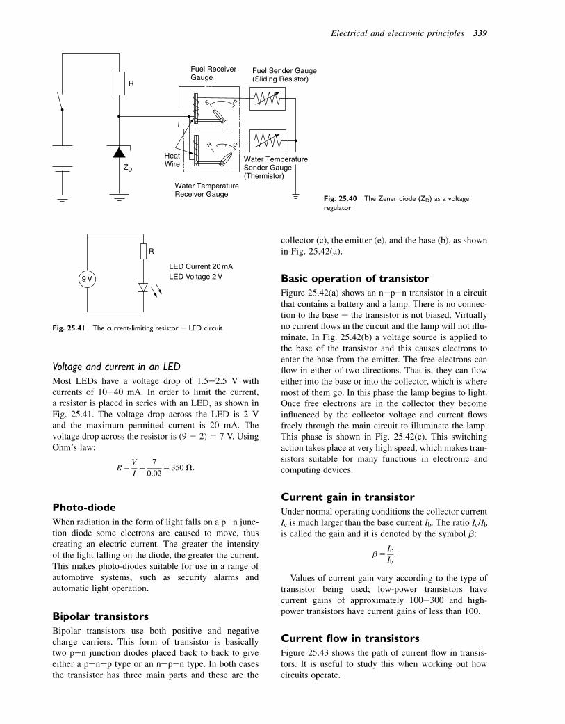
Voltage and current in an LED
Most LEDs have a voltage drop of 1.5e2.5 V withcurrents of 10e40 mA. In order to limit the current,a resistor is placed in series with an LED, as shown inFig. 25.41. The voltage drop across the LED is 2 Vand the maximum permitted current is 20 mA. Thevoltage drop across the resistor is (9 2 2) 5 7 V. UsingOhm’s law:
R5V
I5
7
0:025 350 V:
Photo-diode
When radiation in the form of light falls on a pen junc-tion diode some electrons are caused to move, thuscreating an electric current. The greater the intensityof the light falling on the diode, the greater the current.This makes photo-diodes suitable for use in a range ofautomotive systems, such as security alarms andautomatic light operation.
Bipolar transistors
Bipolar transistors use both positive and negativecharge carriers. This form of transistor is basicallytwo pen junction diodes placed back to back to giveeither a penep type or an nepen type. In both casesthe transistor has three main parts and these are the
collector (c), the emitter (e), and the base (b), as shownin Fig. 25.42(a).
Basic operation of transistor
Figure 25.42(a) shows an nepen transistor in a circuitthat contains a battery and a lamp. There is no connec-tion to the base e the transistor is not biased. Virtuallyno current flows in the circuit and the lamp will not illu-minate. In Fig. 25.42(b) a voltage source is applied tothe base of the transistor and this causes electrons toenter the base from the emitter. The free electrons canflow in either of two directions. That is, they can floweither into the base or into the collector, which is wheremost of them go. In this phase the lamp begins to light.Once free electrons are in the collector they becomeinfluenced by the collector voltage and current flowsfreely through the main circuit to illuminate the lamp.This phase is shown in Fig. 25.42(c). This switchingaction takes place at very high speed, which makes tran-sistors suitable for many functions in electronic andcomputing devices.
Current gain in transistor
Under normal operating conditions the collector currentIc is much larger than the base current Ib. The ratio Ic/Ibis called the gain and it is denoted by the symbol b:
b5IcIb:
Values of current gain vary according to the type oftransistor being used; low-power transistors havecurrent gains of approximately 100e300 and high-power transistors have current gains of less than 100.
Current flow in transistors
Figure 25.43 shows the path of current flow in transis-tors. It is useful to study this when working out howcircuits operate.
Fuel ReceiverGauge
Fuel Sender Gauge(Sliding Resistor)
R
E
HI
F
C
ZD
HeatWire
Water TemperatureReceiver Gauge
Water TemperatureSender Gauge(Thermistor)
Fig. 25.40 The Zener diode (ZD) as a voltage
regulator
R
9 V
LED Current 20 mALED Voltage 2 V
Fig. 25.41 The current-limiting resistor e LED circuit
Electrical and electronic principles 339

Transistor circuit used in automotiveapplications
Voltage amplifier
Some devices such as sensors in vehicle systemsproduce weak electrical outputs. These weak outputsare amplified (increased voltage) to make them suit-able for use in operating a vehicle system. The circuitshown in Fig. 25.44 shows a simple voltage amplifiercircuit.
Darlington pair
A Darlington pair is a circuit that contains two transis-tors, as shown in Fig. 25.45. The effect is that thecircuit behaves as a single transistor with a very highcurrent gain. The collector current from T1 is fed tothe base of T2. In the example shown, the transistorseach have a current gain b 5 200; this gives a collectorcurrent at T1 of 0.3 mA, which becomes the basecurrent of T2 and the resulting collector current at T2
is 200 3 0.3 5 60 mA. A Darlington pair is oftenused to provide the current for the primary windingof an ignition coil.
Heat sink
Semiconductor devices are adversely affected bytemperatures outside their designed operating range.
p
c en n
b
LampOff
p
ec
n nb
LampBegins to Light
(a) (b) (c)
p
ec
n nb
LampFull On
Fig. 25.42 Transistor basics
R
+ Pos _ Neg
b
c
e
b
c
e
npn Common Emitter
(a) (b)
pnp Common Emitter
Ic Ic
Ib
IbIb
Ie = Ib + Ic
Fig. 25.43 Current flow in transistors
Rb
C1
Low VoltageHigh Voltage
C2
Rc
Fig. 25.44 Voltage amplifier
0.0015 mA
0.3 mA60 mA
β = 200T1
T2
β = 200
Fig. 25.45 Darlington pair
340 A Practical Approach to Motor Vehicle Engineering and Maintenance
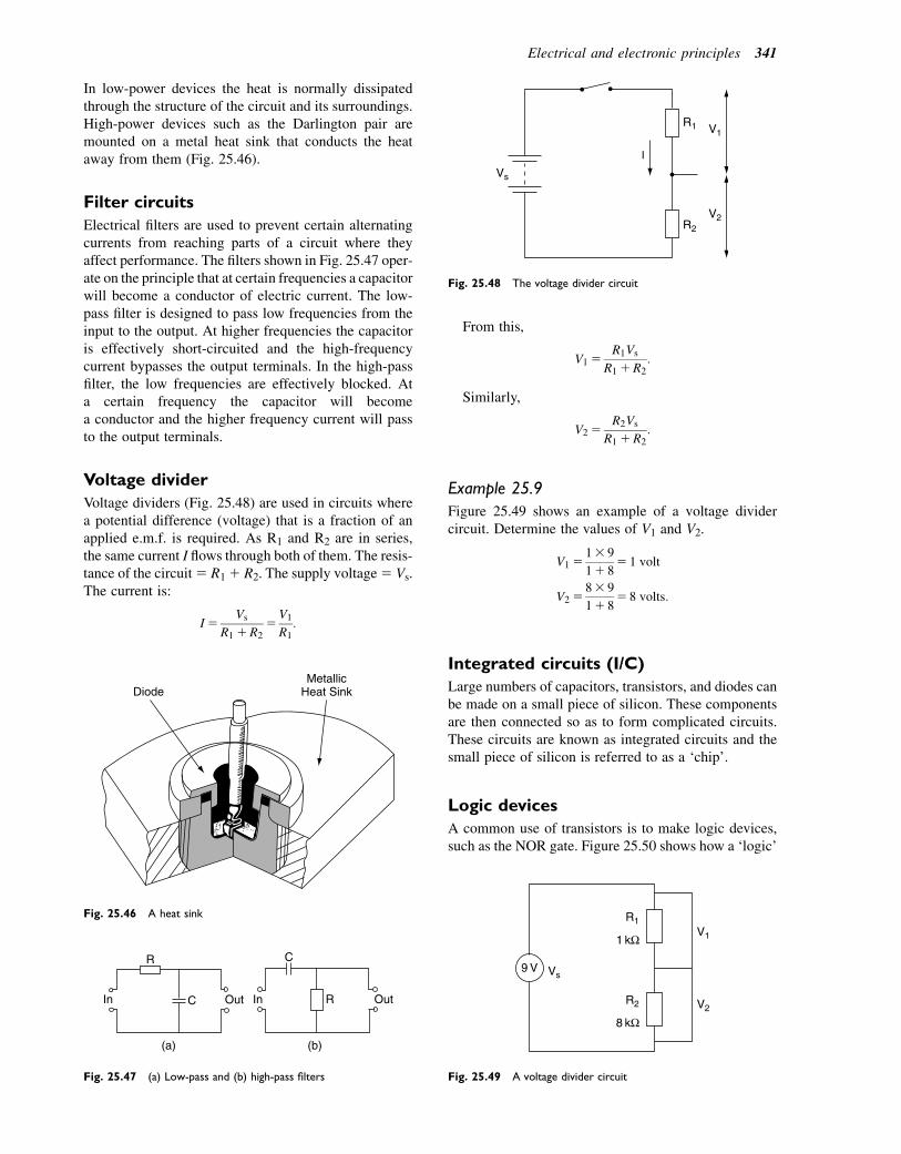
In low-power devices the heat is normally dissipatedthrough the structure of the circuit and its surroundings.High-power devices such as the Darlington pair aremounted on a metal heat sink that conducts the heataway from them (Fig. 25.46).
Filter circuits
Electrical filters are used to prevent certain alternatingcurrents from reaching parts of a circuit where theyaffect performance. The filters shown in Fig. 25.47 oper-ate on the principle that at certain frequencies a capacitorwill become a conductor of electric current. The low-pass filter is designed to pass low frequencies from theinput to the output. At higher frequencies the capacitoris effectively short-circuited and the high-frequencycurrent bypasses the output terminals. In the high-passfilter, the low frequencies are effectively blocked. Ata certain frequency the capacitor will becomea conductor and the higher frequency current will passto the output terminals.
Voltage divider
Voltage dividers (Fig. 25.48) are used in circuits wherea potential difference (voltage) that is a fraction of anapplied e.m.f. is required. As R1 and R2 are in series,the same current I flows through both of them. The resis-tance of the circuit5 R11 R2. The supply voltage5 Vs.The current is:
I5Vs
R11R25V1
R1:
From this,
V15R1Vs
R11R2:
Similarly,
V25R2Vs
R11R2:
Example 25.9
Figure 25.49 shows an example of a voltage dividercircuit. Determine the values of V1 and V2.
V1513 9
11 85 1 volt
V2583 9
11 85 8 volts:
Integrated circuits (I/C)
Large numbers of capacitors, transistors, and diodes canbe made on a small piece of silicon. These componentsare then connected so as to form complicated circuits.These circuits are known as integrated circuits and thesmall piece of silicon is referred to as a ‘chip’.
Logic devices
A common use of transistors is to make logic devices,such as the NOR gate. Figure 25.50 shows how a ‘logic’
DiodeMetallic
Heat Sink
Fig. 25.46 A heat sink
R
(a) (b)
OutCIn R
C
OutIn
Fig. 25.47 (a) Low-pass and (b) high-pass filters
I
R1
R2
V2
V1
Vs
Fig. 25.48 The voltage divider circuit
R1V1
V2
Vs
R2
1 kΩ
8 kΩ
9 V
Fig. 25.49 A voltage divider circuit
Electrical and electronic principles 341
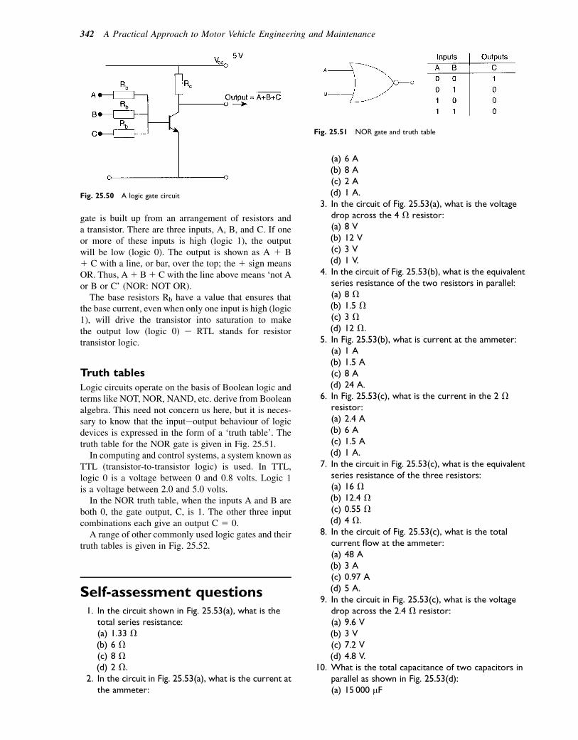
gate is built up from an arrangement of resistors anda transistor. There are three inputs, A, B, and C. If oneor more of these inputs is high (logic 1), the outputwill be low (logic 0). The output is shown as A 1 B1 C with a line, or bar, over the top; the 1 sign meansOR. Thus, A1 B1 C with the line above means ‘not Aor B or C’ (NOR: NOT OR).
The base resistors Rb have a value that ensures thatthe base current, even when only one input is high (logic1), will drive the transistor into saturation to makethe output low (logic 0) e RTL stands for resistortransistor logic.
Truth tables
Logic circuits operate on the basis of Boolean logic andterms like NOT, NOR, NAND, etc. derive from Booleanalgebra. This need not concern us here, but it is neces-sary to know that the inputeoutput behaviour of logicdevices is expressed in the form of a ‘truth table’. Thetruth table for the NOR gate is given in Fig. 25.51.
In computing and control systems, a system known asTTL (transistor-to-transistor logic) is used. In TTL,logic 0 is a voltage between 0 and 0.8 volts. Logic 1is a voltage between 2.0 and 5.0 volts.
In the NOR truth table, when the inputs A and B areboth 0, the gate output, C, is 1. The other three inputcombinations each give an output C 5 0.A range of other commonly used logic gates and their
truth tables is given in Fig. 25.52.
Self-assessment questions1. In the circuit shown in Fig. 25.53(a), what is the
total series resistance:(a) 1.33 V(b) 6 V(c) 8 V(d) 2 V.
2. In the circuit in Fig. 25.53(a), what is the current atthe ammeter:
(a) 6 A(b) 8 A(c) 2 A(d) 1 A.
3. In the circuit of Fig. 25.53(a), what is the voltagedrop across the 4 V resistor:(a) 8 V(b) 12 V(c) 3 V(d) 1 V.
4. In the circuit of Fig. 25.53(b), what is the equivalentseries resistance of the two resistors in parallel:(a) 8 V(b) 1.5 V(c) 3 V(d) 12 V.
5. In Fig. 25.53(b), what is current at the ammeter:(a) 1 A(b) 1.5 A(c) 8 A(d) 24 A.
6. In Fig. 25.53(c), what is the current in the 2 Vresistor:(a) 2.4 A(b) 6 A(c) 1.5 A(d) 1 A.
7. In the circuit in Fig. 25.53(c), what is the equivalentseries resistance of the three resistors:(a) 16 V(b) 12.4 V(c) 0.55 V(d) 4 V.
8. In the circuit of Fig. 25.53(c), what is the totalcurrent flow at the ammeter:(a) 48 A(b) 3 A(c) 0.97 A(d) 5 A.
9. In the circuit in Fig. 25.53(c), what is the voltagedrop across the 2.4 V resistor:(a) 9.6 V(b) 3 V(c) 7.2 V(d) 4.8 V.
10. What is the total capacitance of two capacitors inparallel as shown in Fig. 25.53(d):(a) 15 000 mF
Fig. 25.50 A logic gate circuit
Fig. 25.51 NOR gate and truth table
342 A Practical Approach to Motor Vehicle Engineering and Maintenance
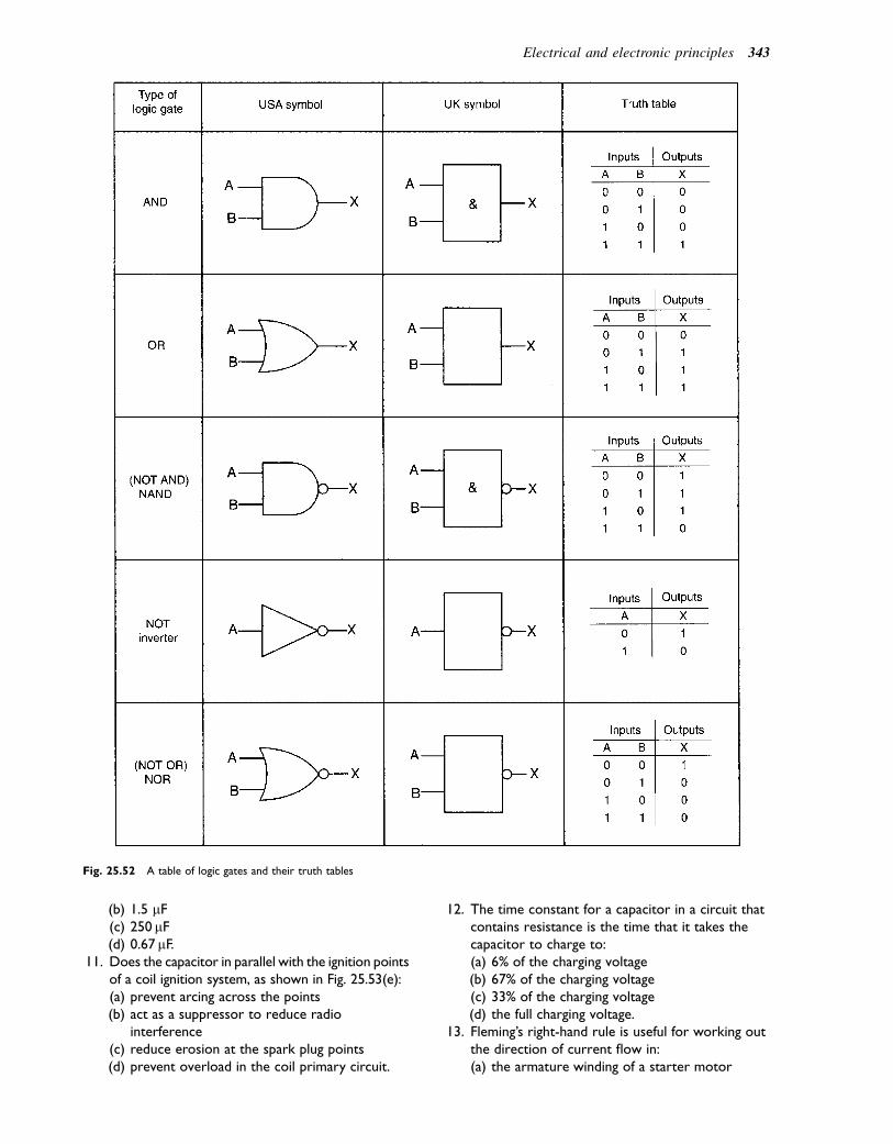
(b) 1.5 mF(c) 250mF(d) 0.67mF.
11. Does the capacitor in parallel with the ignition pointsof a coil ignition system, as shown in Fig. 25.53(e):(a) prevent arcing across the points(b) act as a suppressor to reduce radio
interference(c) reduce erosion at the spark plug points(d) prevent overload in the coil primary circuit.
12. The time constant for a capacitor in a circuit thatcontains resistance is the time that it takes thecapacitor to charge to:(a) 6% of the charging voltage(b) 67% of the charging voltage(c) 33% of the charging voltage(d) the full charging voltage.
13. Fleming’s right-hand rule is useful for working outthe direction of current flow in:(a) the armature winding of a starter motor
Fig. 25.52 A table of logic gates and their truth tables
Electrical and electronic principles 343

(b) the armature winding of a generator(c) the winding of a non-inductive resistor(d) a solenoid.
14. Impedance in an a.c. circuit is the total oppositionto current flow that the circuit causes. Is impedancemeasured in:(a) watts(b) amperes(c) ohms(d) coulombs.
15. In a metal conductor the flow of current is causedby the drift of free electrons under the influence ofan applied e.m.f. Is the free electron flow:(a) from the positive to the negative electrode(b) from low electrical potential to higher electrical
potential(c) from the positive to the negative terminal of the
battery(d) From high electrical potential to low electrical
potential.16. A 12-volt electric motor takes a current of 20 A.
The power of the motor is:(a) 1.67 kW(b) 0.3 kW(c) 240 W(d) 32 W.
17. Lenz’s law states that:(a) The direction of an induced e.m.f. is always such
that it tends to set up a current opposing thechange that is responsible for inducing the e.m.f.
(b) V 5 IR(c) T 5 RC(d) The back e.m.f. is directly proportional to the
capacitance.18. Electrical conductors are materials:
(a) in which free electrons can be made to move(b) that have a high specific resistance(c) that do not heat up when electric current flows
in them(d) that are always physically hard.
19. A circuit that has a resistance of 10 000 V anda capacitance of 10 000 mF has a time constant of:(a) 10 seconds(b) 0.1 seconds(c) 100 seconds(d) 1000 seconds.
20. Are electronic components such as alternatordiodes mounted on a heat sink:(a) to avoid damage by vibration(b) to conduct surplus electricity to earth(c) to allow heat to be conducted away from
a diode to prevent damage(d) to improve the electrical conductivity of the
circuit.21. A certain transistor has a current gain of 100.
When the base current of this transistor is 0.1 mAthe collector current is:
4 Ω 2 Ω
V
A
12 V
(a)
2 Ω
6 Ω A
12 V
(b)
2 Ω
8 Ω
2.4 Ω
A
V
12 V
(c)
C1 = 100 μF
C2 = 150 μF
(d)
C Contact Breaker Points
Ignition Coil Primary
(e)
Fig. 25.53 Circuit diagrams
344 A Practical Approach to Motor Vehicle Engineering and Maintenance
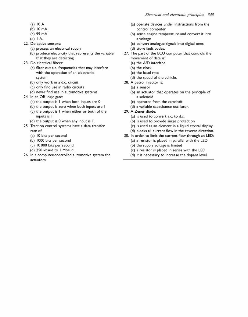
(a) 10 A(b) 10 mA(c) 99 mA(d) 1 A.
22. Do active sensors:(a) process an electrical supply(b) produce electricity that represents the variable
that they are detecting.23. Do electrical filters:
(a) filter out a.c. frequencies that may interferewith the operation of an electronicsystem
(b) only work in a d.c. circuit(c) only find use in radio circuits(d) never find use in automotive systems.
24. In an OR logic gate:(a) the output is 1 when both inputs are 0(b) the output is zero when both inputs are 1(c) the output is 1 when either or both of the
inputs is 1(d) the output is 0 when any input is 1.
25. Traction control systems have a data transferrate of:(a) 10 bits per second(b) 1000 bits per second(c) 10 000 bits per second(d) 250 kbaud to 1 Mbaud.
26. In a computer-controlled automotive system theactuators:
(a) operate devices under instructions from thecontrol computer
(b) sense engine temperature and convert it intoa voltage
(c) convert analogue signals into digital ones(d) store fault codes.
27. The part of the ECU computer that controls themovement of data is:(a) the A/D interface(b) the clock(c) the baud rate(d) the speed of the vehicle.
28. A petrol injector is:(a) a sensor(b) an actuator that operates on the principle of
a solenoid(c) operated from the camshaft(d) a variable capacitance oscillator.
29. A Zener diode:(a) is used to convert a.c. to d.c.(b) is used to provide surge protection(c) is used as an element in a liquid crystal display(d) blocks all current flow in the reverse direction.
30. In order to limit the current flow through an LED:(a) a resistor is placed in parallel with the LED(b) the supply voltage is limited(c) a resistor is placed in series with the LED(d) it is necessary to increase the dopant level.
Electrical and electronic principles 345
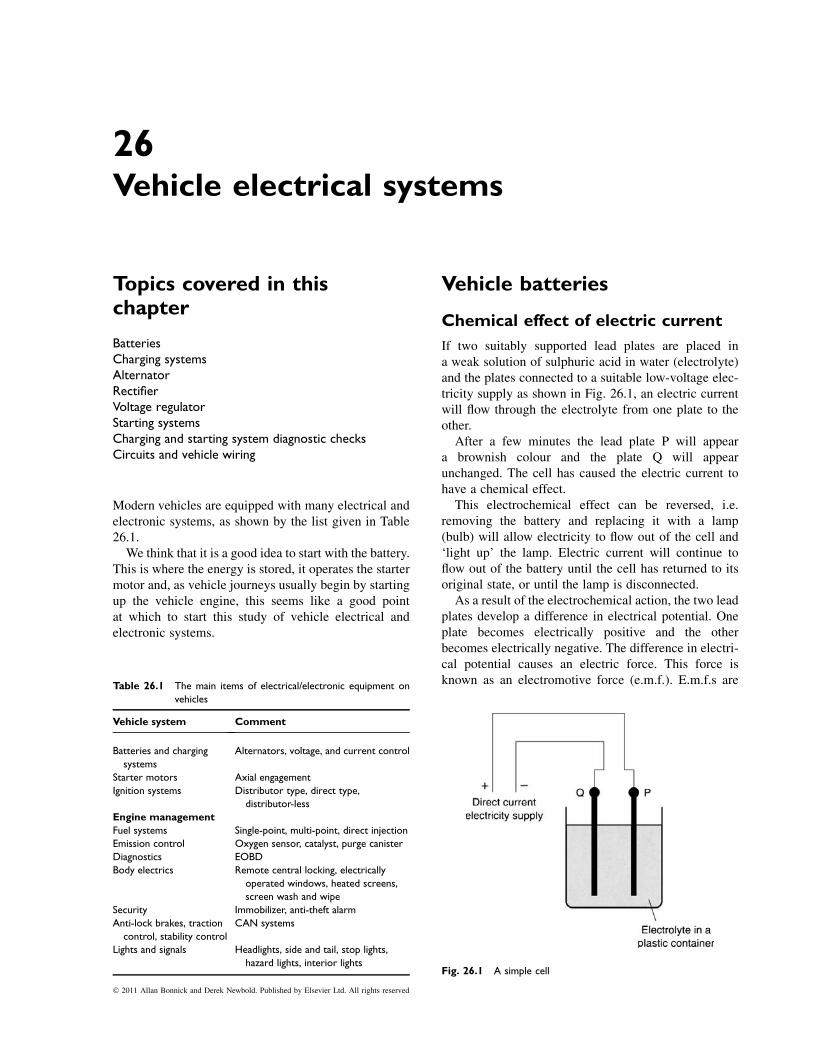
26Vehicle electrical systems
Topics covered in thischapter
BatteriesCharging systemsAlternatorRectifierVoltage regulatorStarting systemsCharging and starting system diagnostic checksCircuits and vehicle wiring
Modern vehicles are equipped with many electrical andelectronic systems, as shown by the list given in Table26.1.
We think that it is a good idea to start with the battery.This is where the energy is stored, it operates the startermotor and, as vehicle journeys usually begin by startingup the vehicle engine, this seems like a good pointat which to start this study of vehicle electrical andelectronic systems.
Vehicle batteries
Chemical effect of electric current
If two suitably supported lead plates are placed ina weak solution of sulphuric acid in water (electrolyte)and the plates connected to a suitable low-voltage elec-tricity supply as shown in Fig. 26.1, an electric currentwill flow through the electrolyte from one plate to theother.
After a few minutes the lead plate P will appeara brownish colour and the plate Q will appearunchanged. The cell has caused the electric current tohave a chemical effect.
This electrochemical effect can be reversed, i.e.removing the battery and replacing it with a lamp(bulb) will allow electricity to flow out of the cell and‘light up’ the lamp. Electric current will continue toflow out of the battery until the cell has returned to itsoriginal state, or until the lamp is disconnected.
As a result of the electrochemical action, the two leadplates develop a difference in electrical potential. Oneplate becomes electrically positive and the otherbecomes electrically negative. The difference in electri-cal potential causes an electric force. This force isknown as an electromotive force (e.m.f.). E.m.f.s are
Fig. 26.1 A simple cell
Table 26.1 The main items of electrical/electronic equipment on
vehicles
Vehicle system Comment
Batteries and charging
systems
Alternators, voltage, and current control
Starter motors Axial engagement
Ignition systems Distributor type, direct type,
distributor-less
Engine management
Fuel systems Single-point, multi-point, direct injection
Emission control Oxygen sensor, catalyst, purge canister
Diagnostics EOBD
Body electrics Remote central locking, electrically
operated windows, heated screens,
screen wash and wipe
Security Immobilizer, anti-theft alarm
Anti-lock brakes, traction
control, stability control
CAN systems
Lights and signals Headlights, side and tail, stop lights,
hazard lights, interior lights
� 2011 Allan Bonnick and Derek Newbold. Published by Elsevier Ltd. All rights reserved
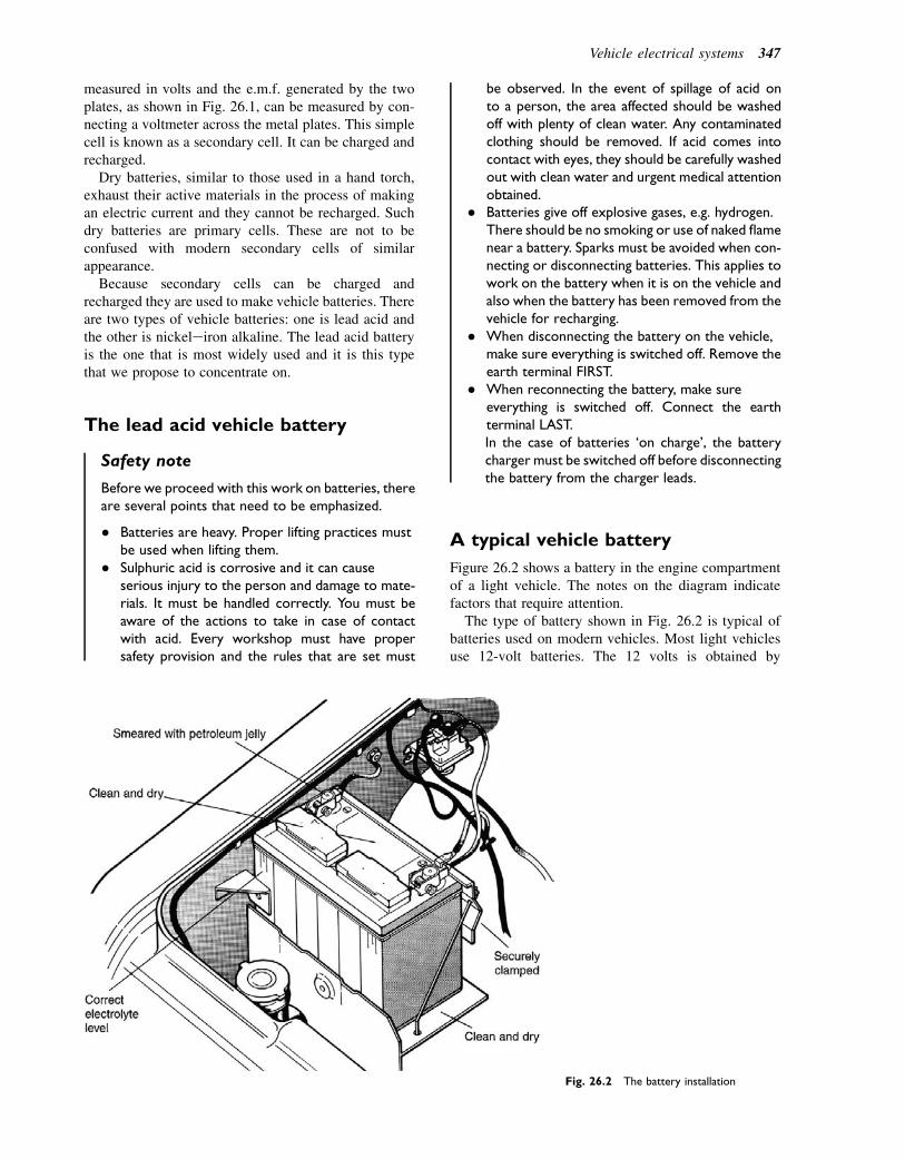
measured in volts and the e.m.f. generated by the twoplates, as shown in Fig. 26.1, can be measured by con-necting a voltmeter across the metal plates. This simplecell is known as a secondary cell. It can be charged andrecharged.
Dry batteries, similar to those used in a hand torch,exhaust their active materials in the process of makingan electric current and they cannot be recharged. Suchdry batteries are primary cells. These are not to beconfused with modern secondary cells of similarappearance.
Because secondary cells can be charged andrecharged they are used to make vehicle batteries. Thereare two types of vehicle batteries: one is lead acid andthe other is nickeleiron alkaline. The lead acid batteryis the one that is most widely used and it is this typethat we propose to concentrate on.
The lead acid vehicle battery
Safety note
Before we proceed with this work on batteries, thereare several points that need to be emphasized.
� Batteries are heavy. Proper lifting practices mustbe used when lifting them.
� Sulphuric acid is corrosive and it can causeserious injury to the person and damage to mate-rials. It must be handled correctly. You must beaware of the actions to take in case of contactwith acid. Every workshop must have propersafety provision and the rules that are set must
be observed. In the event of spillage of acid onto a person, the area affected should be washedoff with plenty of clean water. Any contaminatedclothing should be removed. If acid comes intocontact with eyes, they should be carefully washedout with clean water and urgent medical attentionobtained.
� Batteries give off explosive gases, e.g. hydrogen.There should be no smoking or use of naked flamenear a battery. Sparks must be avoided when con-necting or disconnecting batteries. This applies towork on the battery when it is on the vehicle andalso when the battery has been removed from thevehicle for recharging.
� When disconnecting the battery on the vehicle,make sure everything is switched off. Remove theearth terminal FIRST.
� When reconnecting the battery, make sureeverything is switched off. Connect the earthterminal LAST.In the case of batteries ‘on charge’, the batterycharger must be switched off before disconnectingthe battery from the charger leads.
A typical vehicle battery
Figure 26.2 shows a battery in the engine compartmentof a light vehicle. The notes on the diagram indicatefactors that require attention.
The type of battery shown in Fig. 26.2 is typical ofbatteries used on modern vehicles. Most light vehiclesuse 12-volt batteries. The 12 volts is obtained by
Fig. 26.2 The battery installation
Vehicle electrical systems 347
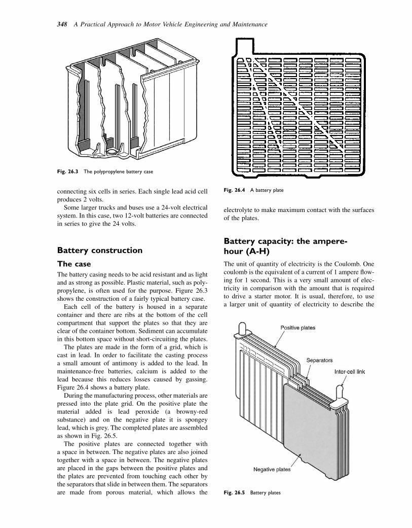
connecting six cells in series. Each single lead acid cellproduces 2 volts.
Some larger trucks and buses use a 24-volt electricalsystem. In this case, two 12-volt batteries are connectedin series to give the 24 volts.
Battery construction
The case
The battery casing needs to be acid resistant and as lightand as strong as possible. Plastic material, such as poly-propylene, is often used for the purpose. Figure 26.3shows the construction of a fairly typical battery case.
Each cell of the battery is housed in a separatecontainer and there are ribs at the bottom of the cellcompartment that support the plates so that they areclear of the container bottom. Sediment can accumulatein this bottom space without short-circuiting the plates.
The plates are made in the form of a grid, which iscast in lead. In order to facilitate the casting processa small amount of antimony is added to the lead. Inmaintenance-free batteries, calcium is added to thelead because this reduces losses caused by gassing.Figure 26.4 shows a battery plate.
During the manufacturing process, other materials arepressed into the plate grid. On the positive plate thematerial added is lead peroxide (a browny-redsubstance) and on the negative plate it is spongeylead, which is grey. The completed plates are assembledas shown in Fig. 26.5.
The positive plates are connected together witha space in between. The negative plates are also joinedtogether with a space in between. The negative platesare placed in the gaps between the positive plates andthe plates are prevented from touching each other bythe separators that slide in between them. The separatorsare made from porous material, which allows the
electrolyte to make maximum contact with the surfacesof the plates.
Battery capacity: the ampere-hour (A-H)
The unit of quantity of electricity is the Coulomb. Onecoulomb is the equivalent of a current of 1 ampere flow-ing for 1 second. This is a very small amount of elec-tricity in comparison with the amount that is requiredto drive a starter motor. It is usual, therefore, to usea larger unit of quantity of electricity to describe the
Fig. 26.3 The polypropylene battery case
Fig. 26.4 A battery plate
Fig. 26.5 Battery plates
348 A Practical Approach to Motor Vehicle Engineering and Maintenance
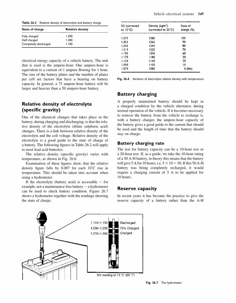
electrical energy capacity of a vehicle battery. The unitthat is used is the ampere-hour. One ampere-hour isequivalent to a current of 1 ampere flowing for 1 hour.The size of the battery plates and the number of platesper cell are factors that have a bearing on batterycapacity. In general, a 75 ampere-hour battery will belarger and heavier than a 50 ampere-hour battery.
Relative density of electrolyte(specific gravity)
One of the chemical changes that takes place in thebattery, during charging and discharging, is that the rela-tive density of the electrolyte (dilute sulphuric acid)changes. There is a link between relative density of theelectrolyte and the cell voltage. Relative density of theelectrolyte is a good guide to the state of charge ofa battery. The following figures in Table 26.2 will applyto most lead acid batteries:
The relative density (specific gravity) varies withtemperature, as shown in Fig. 26.6.
Examination of these figures show, that the relativedensity figure falls by 0.007 for each 108C rise intemperature. This should be taken into account whenusing a hydrometer.
If the electrolyte (battery acid) is accessible e forexample, not a maintenance-free batterye a hydrometercan be used to check battery condition. Figure 26.7shows a hydrometer together with the readings showingthe state of charge.
Battery charging
A properly maintained battery should be kept ina charged condition by the vehicle alternator, duringnormal operation of the vehicle. If it becomes necessaryto remove the battery from the vehicle to recharge it,with a battery charger, the ampere-hour capacity ofthe battery gives a good guide to the current that shouldbe used and the length of time that the battery shouldstay on charge.
Battery charging rate
The test for battery capacity can be a 10-hour test ora 20-hour test. If, as a guide, we take the 10-hour ratingof a 50 A-H battery, in theory this means that the batterywill give 5A for 10 hours, i.e. 53 105 50. If this 50A-Hbattery was being completely recharged, it wouldrequire a charging current of 5 A to be applied for10 hours.
Reserve capacity
In recent years it has become the practice to give thereserve capacity of a battery rather than the A-H
Fig. 26.6 Variation of electrolyte relative density with temperature
Fig. 26.7 The hydrometer
Table 26.2 Relative density of electrolyte and battery charge
State of charge Relative density
Fully charged 1.290
Half charged 1.200
Completely discharged 1.100
Vehicle electrical systems 349
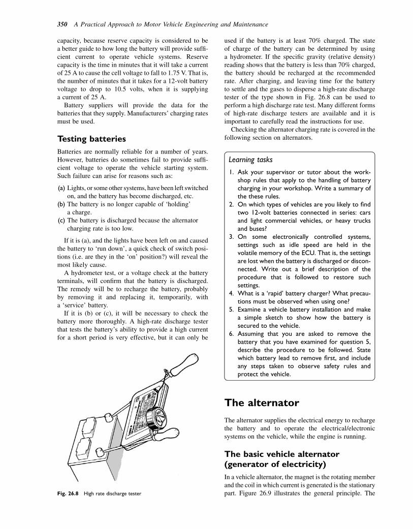
capacity, because reserve capacity is considered to bea better guide to how long the battery will provide suffi-cient current to operate vehicle systems. Reservecapacity is the time in minutes that it will take a currentof 25 A to cause the cell voltage to fall to 1.75 V. That is,the number of minutes that it takes for a 12-volt batteryvoltage to drop to 10.5 volts, when it is supplyinga current of 25 A.
Battery suppliers will provide the data for thebatteries that they supply. Manufacturers’ charging ratesmust be used.
Testing batteries
Batteries are normally reliable for a number of years.However, batteries do sometimes fail to provide suffi-cient voltage to operate the vehicle starting system.Such failure can arise for reasons such as:
(a) Lights, or some other systems, have been left switchedon, and the battery has become discharged, etc.
(b) The battery is no longer capable of ‘holding’a charge.
(c) The battery is discharged because the alternatorcharging rate is too low.
If it is (a), and the lights have been left on and causedthe battery to ‘run down’, a quick check of switch posi-tions (i.e. are they in the ‘on’ position?) will reveal themost likely cause.
A hydrometer test, or a voltage check at the batteryterminals, will confirm that the battery is discharged.The remedy will be to recharge the battery, probablyby removing it and replacing it, temporarily, witha ‘service’ battery.
If it is (b) or (c), it will be necessary to check thebattery more thoroughly. A high-rate discharge testerthat tests the battery’s ability to provide a high currentfor a short period is very effective, but it can only be
used if the battery is at least 70% charged. The stateof charge of the battery can be determined by usinga hydrometer. If the specific gravity (relative density)reading shows that the battery is less than 70% charged,the battery should be recharged at the recommendedrate. After charging, and leaving time for the batteryto settle and the gases to disperse a high-rate dischargetester of the type shown in Fig. 26.8 can be used toperform a high discharge rate test. Many different formsof high-rate discharge testers are available and it isimportant to carefully read the instructions for use.
Checking the alternator charging rate is covered in thefollowing section on alternators.
Learning tasks
1. Ask your supervisor or tutor about the work-shop rules that apply to the handling of batterycharging in your workshop. Write a summary ofthe these rules.
2. On which types of vehicles are you likely to findtwo 12-volt batteries connected in series: carsand light commercial vehicles, or heavy trucksand buses?
3. On some electronically controlled systems,settings such as idle speed are held in thevolatile memory of the ECU. That is, the settingsare lost when the battery is discharged or discon-nected. Write out a brief description of theprocedure that is followed to restore suchsettings.
4. What is a ‘rapid’ battery charger? What precau-tions must be observed when using one?
5. Examine a vehicle battery installation and makea simple sketch to show how the battery issecured to the vehicle.
6. Assuming that you are asked to remove thebattery that you have examined for question 5,describe the procedure to be followed. Statewhich battery lead to remove first, and includeany steps taken to observe safety rules andprotect the vehicle.
The alternator
The alternator supplies the electrical energy to rechargethe battery and to operate the electrical/electronicsystems on the vehicle, while the engine is running.
The basic vehicle alternator(generator of electricity)
In a vehicle alternator, the magnet is the rotating memberand the coil in which current is generated is the stationarypart. Figure 26.9 illustrates the general principle. TheFig. 26.8 High rate discharge tester
350 A Practical Approach to Motor Vehicle Engineering and Maintenance
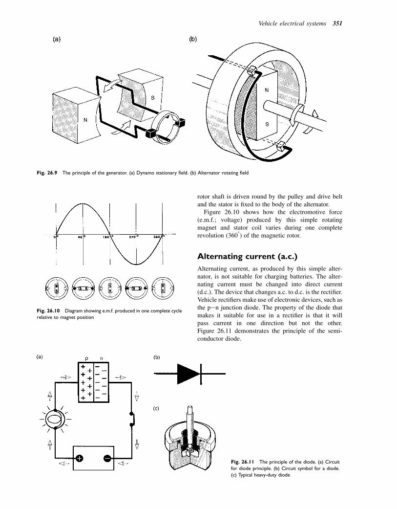
rotor shaft is driven round by the pulley and drive beltand the stator is fixed to the body of the alternator.
Figure 26.10 shows how the electromotive force(e.m.f.; voltage) produced by this simple rotatingmagnet and stator coil varies during one completerevolution (3608) of the magnetic rotor.
Alternating current (a.c.)
Alternating current, as produced by this simple alter-nator, is not suitable for charging batteries. The alter-nating current must be changed into direct current(d.c.). The device that changes a.c. to d.c. is the rectifier.Vehicle rectifiers make use of electronic devices, such asthe pen junction diode. The property of the diode thatmakes it suitable for use in a rectifier is that it willpass current in one direction but not the other.Figure 26.11 demonstrates the principle of the semi-conductor diode.
Fig. 26.9 The principle of the generator. (a) Dynamo stationary field. (b) Alternator rotating field
Fig. 26.10 Diagram showing e.m.f. produced in one complete cycle
relative to magnet position
Fig. 26.11 The principle of the diode. (a) Circuit
for diode principle. (b) Circuit symbol for a diode.
(c) Typical heavy-duty diode
Vehicle electrical systems 351

Using a single diode as a simple half-wave rectifier
As a guide to the principle of operation of the actualrectifier as used in a vehicle alternator, we think that itis useful to briefly consider the operation of the simplehalf-wave rectifier shown in Fig. 26.12.
In this simple rectifier the negative half of the wave is‘blocked’ by the diode. The resulting output is a seriesof positive half-waves separated by 1908. In order toget a smooth d.c. supply it is necessary to use a circuitthat contains several diodes. The bridge circuit rectifieris the basic approach that is used.
A full-wave rectifier: the bridgecircuit
Figure 26.13(a) shows a full-wave rectifier circuit. Thereare four diodes, A, B, C and D, which are connected inbridge form. There is an a.c. input and a voltmeter isconnected across the output resistor.
Reference to Fig. 26.13(b) shows how the currentflows for one half of the a.c. cycle, and Fig. 26.13(c)shows the current flow in the other half of the a.c. cycle.In both cases, the current flows through the load resistorR in the same direction. Thus, the output is directcurrent and this is achieved by the ‘one-way’ action ofthe diodes.
A typical vehicle alternator
The following description of the parts shown inFig. 26.14 should help to develop an understandingthat will aid the additional study and training thatwill build the skills necessary for successful workon electrical/electronic systems.
The rotor
This is where the magnetic field is generated by thecurrent that flows into the rotor windings through theslip rings and brushes. Figure 26.15 shows three typesof rotors that are used in Lucas alternators.
The rotor is made from an iron core around which iswound a coil of wire. The current in this coil of wirecreates a magnetic north pole at one end and a magneticsouth pole at the other of the stator coil. The iron clawsof the rotor are placed on opposite ends of the rotor(field) winding. The ‘fingers’ of the claws are north orsouth magnetic poles, according to the end of the fieldcoil that they are attached to. This makes pairs of northand south poles around the circumference of the rotor.
Fig. 26.12 The half-wave rectifier
Fig. 26.13 The full-wave rectifier. (a) Complete bridge circuit.
(b) Current flow for one half of the voltage waveform. (c) Current
flow for the other half of the voltage waveform
352 A Practical Approach to Motor Vehicle Engineering and Maintenance
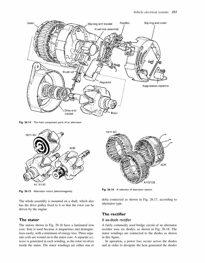
The whole assembly is mounted on a shaft, which alsohas the drive pulley fixed to it so that the rotor can bedriven by the engine.
The stator
The stators shown in Fig. 26.16 have a laminated ironcore. Iron is used because it magnetizes and demagne-tizes easily, with a minimum of energy loss. Three sepa-rate coils are wound on to the stator core. A separate a.c.wave is generated in each winding, as the rotor revolvesinside the stator. The stator windings are either star or
delta connected as shown in Fig. 26.17, according toalternator type.
The rectifier
A six-diode rectifier
A fairly commonly used bridge circuit of an alternatorrectifier uses six diodes, as shown in Fig. 26.18. Thestator windings are connected to the diodes as shownin this figure.
In operation, a power loss occurs across the diodesand in order to dissipate the heat generated the diodes
Fig. 26.14 The main component parts of an alternator
Fig. 26.15 Alternator rotors (electromagnets)Fig. 26.16 A selection of alternator stators
Vehicle electrical systems 353
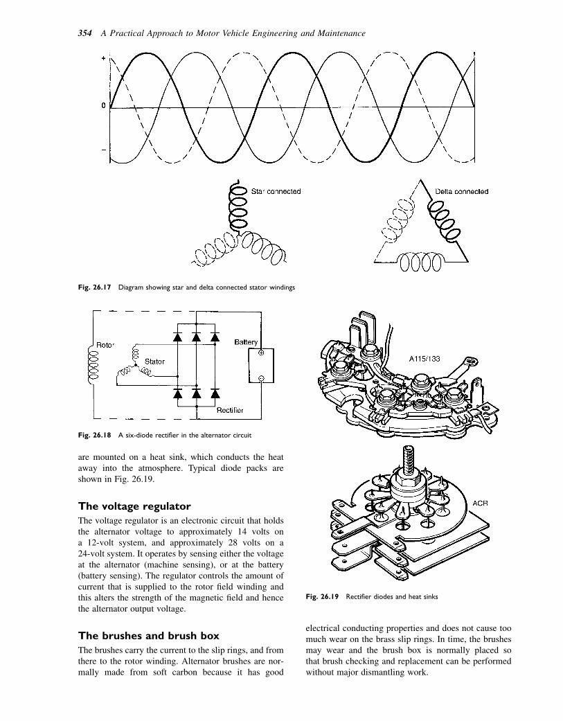
are mounted on a heat sink, which conducts the heataway into the atmosphere. Typical diode packs areshown in Fig. 26.19.
The voltage regulator
The voltage regulator is an electronic circuit that holdsthe alternator voltage to approximately 14 volts ona 12-volt system, and approximately 28 volts on a24-volt system. It operates by sensing either the voltageat the alternator (machine sensing), or at the battery(battery sensing). The regulator controls the amount ofcurrent that is supplied to the rotor field winding andthis alters the strength of the magnetic field and hencethe alternator output voltage.
The brushes and brush box
The brushes carry the current to the slip rings, and fromthere to the rotor winding. Alternator brushes are nor-mally made from soft carbon because it has good
electrical conducting properties and does not cause toomuch wear on the brass slip rings. In time, the brushesmay wear and the brush box is normally placed sothat brush checking and replacement can be performedwithout major dismantling work.
Fig. 26.17 Diagram showing star and delta connected stator windings
Fig. 26.18 A six-diode rectifier in the alternator circuit
Fig. 26.19 Rectifier diodes and heat sinks
354 A Practical Approach to Motor Vehicle Engineering and Maintenance
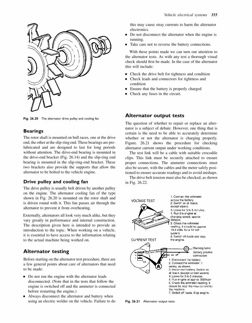
Bearings
The rotor shaft is mounted on ball races, one at the driveend, the other at the slip-ring end. These bearings are pre-lubricated and are designed to last for long periodswithout attention. The drive-end bearing is mounted inthe drive-end bracket (Fig. 26.14) and the slip-ring endbearing is mounted in the slip-ring-end bracket. Thesetwo brackets also provide the supports that allow thealternator to be bolted to the vehicle engine.
Drive pulley and cooling fan
The drive pulley is usually belt driven by another pulleyon the engine. The alternator cooling fan of the typeshown in Fig. 26.20 is mounted on the rotor shaft andis driven round with it. This fan passes air through thealternator to prevent it from overheating.
Externally, alternators all look very much alike, but theyvary greatly in performance and internal construction.The description given here is intended to provide anintroduction to the topic. When working on a vehicle,it is essential to have access to the information relatingto the actual machine being worked on.
Alternator testing
Before starting on the alternator test procedure, there area few general points about care of alternators that needto be made:
� Do not run the engine with the alternator leadsdisconnected. (Note that in the tests that follow theengine is switched off and the ammeter is connectedbefore restarting the engine.)
� Always disconnect the alternator and battery whenusing an electric welder on the vehicle. Failure to do
this may cause stray currents to harm the alternatorelectronics.
� Do not disconnect the alternator when the engine isrunning.
� Take care not to reverse the battery connections.
With these points made we can turn our attention tothe alternator tests. As with any test a thorough visualcheck should first be made. In the case of the alternatorthis will include:
� Check the drive belt for tightness and condition� Check leads and connectors for tightness and
condition� Ensure that the battery is properly charged� Check any fuses in the circuit.
Alternator output tests
The question of whether to repair or replace an alter-nator is a subject of debate. However, one thing that iscertain is the need to be able to accurately determinewhether or not the alternator is charging properly.Figure. 26.21 shows the procedure for checkingalternator current output under working conditions.
The test link will be a cable with suitable crocodileclips. This link must be securely attached to ensureproper connections. The ammeter connections mustalso be secure, with the cables and the meter safely posi-tioned to ensure accurate readings and to avoid mishaps.
The drive belt tension must also be checked, as shownin Fig. 26.22.
Fig. 26.20 The alternator drive pulley and cooling fan
Fig. 26.21 Alternator output tests
Vehicle electrical systems 355
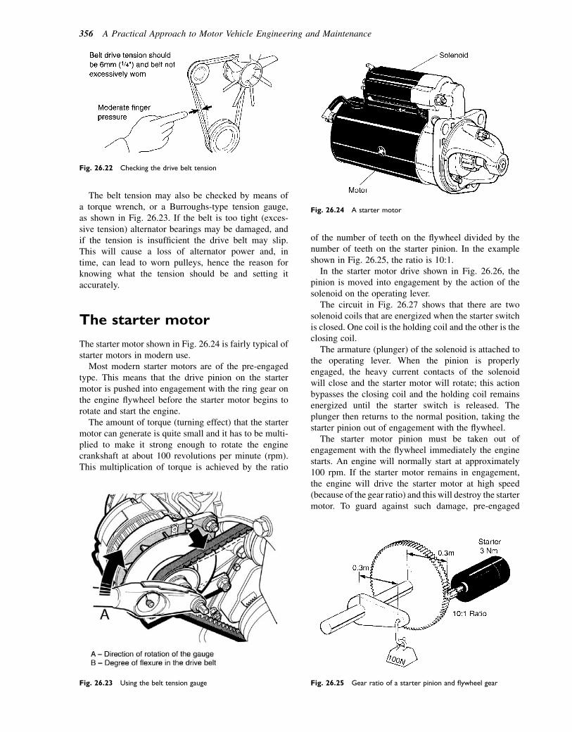
The belt tension may also be checked by means ofa torque wrench, or a Burroughs-type tension gauge,as shown in Fig. 26.23. If the belt is too tight (exces-sive tension) alternator bearings may be damaged, andif the tension is insufficient the drive belt may slip.This will cause a loss of alternator power and, intime, can lead to worn pulleys, hence the reason forknowing what the tension should be and setting itaccurately.
The starter motor
The starter motor shown in Fig. 26.24 is fairly typical ofstarter motors in modern use.
Most modern starter motors are of the pre-engagedtype. This means that the drive pinion on the startermotor is pushed into engagement with the ring gear onthe engine flywheel before the starter motor begins torotate and start the engine.
The amount of torque (turning effect) that the startermotor can generate is quite small and it has to be multi-plied to make it strong enough to rotate the enginecrankshaft at about 100 revolutions per minute (rpm).This multiplication of torque is achieved by the ratio
of the number of teeth on the flywheel divided by thenumber of teeth on the starter pinion. In the exampleshown in Fig. 26.25, the ratio is 10:1.
In the starter motor drive shown in Fig. 26.26, thepinion is moved into engagement by the action of thesolenoid on the operating lever.
The circuit in Fig. 26.27 shows that there are twosolenoid coils that are energized when the starter switchis closed. One coil is the holding coil and the other is theclosing coil.
The armature (plunger) of the solenoid is attached tothe operating lever. When the pinion is properlyengaged, the heavy current contacts of the solenoidwill close and the starter motor will rotate; this actionbypasses the closing coil and the holding coil remainsenergized until the starter switch is released. Theplunger then returns to the normal position, taking thestarter pinion out of engagement with the flywheel.
The starter motor pinion must be taken out ofengagement with the flywheel immediately the enginestarts. An engine will normally start at approximately100 rpm. If the starter motor remains in engagement,the engine will drive the starter motor at high speed(because of the gear ratio) and this will destroy the startermotor. To guard against such damage, pre-engaged
Fig. 26.22 Checking the drive belt tension
Fig. 26.23 Using the belt tension gauge
Fig. 26.24 A starter motor
Fig. 26.25 Gear ratio of a starter pinion and flywheel gear
356 A Practical Approach to Motor Vehicle Engineering and Maintenance

starter motors are equipped with a free-wheelingdevice. A common example of such an over-runprotection device is the roller clutch drive assemblyshown in Fig. 26.28. The inner member is fixed tothe starter motor shaft and the outer member to thestarter motor pinion.
This is a convenient point at which to have a look atsome tests that can be used to trace faults in startermotor circuits.
Testing starter motor circuits
As with all diagnostic work, it is advisable to adopta strategy. One strategy that works well is the six-stepapproach. The six steps are:
1. Collect evidence2. Analyse evidence3. Locate the fault4. Find the cause of the fault and remedy it5. Rectify the fault (if different from 4)6. Test the system to verify that repair is correct.
In the case of a starter motor system and assumingthat the starter motor does not operate when the switchis on, step 1 of the six steps will include a visual check tosee whether all readily visible parts such as cables, etc.are in place and secure. The next step would be to checkthe battery. An indication of battery condition can beobtained by switching on the headlights. If the starterswitch is operated with the headlights on and the lightsgo dim, there is a case for a battery test, as described inthe section on batteries.
If the battery condition is correct, there are somevoltmeter tests that can be performed to check variousparts of the starter motor circuit. For these tests, it isbest to use an assistant to operate the starter switchbecause it is unwise to attempt to make the meterconnections and observe the meter readings in thevicinity of the starter motor and attempt to operatethe starter switch simultaneously. The meter must beset to the correct d.c. range and clips should be usedso that secure connections can be made to the variouspoints indicated.
To avoid unwanted start-up, the ignition systemshould be disabled. On a coil ignition system, the lowtension lead between the coil and distributor should bedisconnected. On a compression ignition (diesel)engine, the fuel supply should be cut off, probably byoperating the stop control. The instructions that relateto the vehicle being worked on must be referred to;this warning is particularly important when workingon engine management systems, because fault codesmay be generated.
Figure 26.29 shows the test to check voltage at thebattery terminals under load.
Here the battery voltage is being checked while thestarter switch is being operated. For a 12-volt systemon a petrol-engined vehicle, the voltmeter should showa reading of approximately 10 volts. On a diesel-enginedvehicle, the load on the battery is higher and the voltagereading will be lower; approximately 9 volts should beobtained.
The starter terminal voltage
The purpose of the test shown in Fig. 26.30, is to checkthe heavy current circuit of the starter motor and the
Fig. 26.26 The operating lever
Fig. 26.27 The starter solenoid
Fig. 26.28 Starter pinion over-run protection
Vehicle electrical systems 357
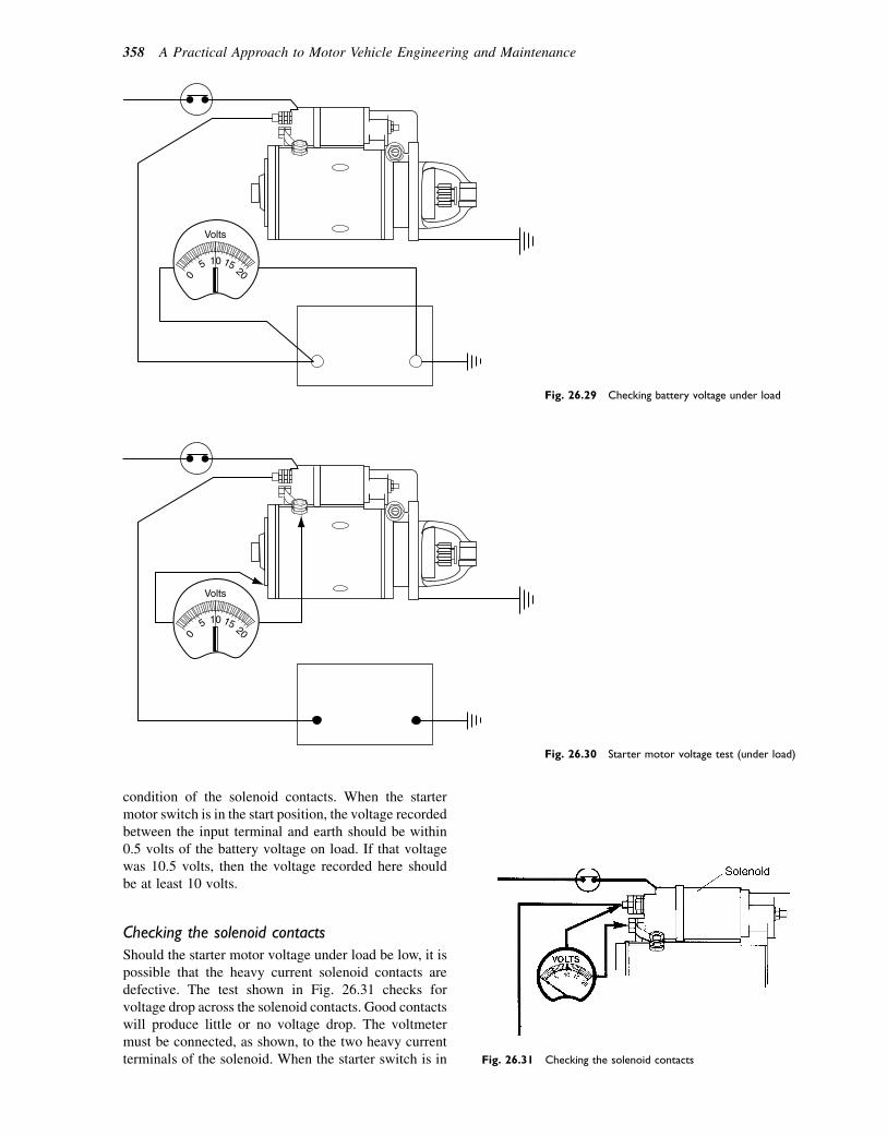
condition of the solenoid contacts. When the startermotor switch is in the start position, the voltage recordedbetween the input terminal and earth should be within0.5 volts of the battery voltage on load. If that voltagewas 10.5 volts, then the voltage recorded here shouldbe at least 10 volts.
Checking the solenoid contacts
Should the starter motor voltage under load be low, it ispossible that the heavy current solenoid contacts aredefective. The test shown in Fig. 26.31 checks forvoltage drop across the solenoid contacts. Good contactswill produce little or no voltage drop. The voltmetermust be connected, as shown, to the two heavy currentterminals of the solenoid. When the starter switch is in
0
5 10 15 20
Volts
Fig. 26.29 Checking battery voltage under load
0
5 10 15 20
Volts
Fig. 26.30 Starter motor voltage test (under load)
Fig. 26.31 Checking the solenoid contacts
358 A Practical Approach to Motor Vehicle Engineering and Maintenance

the off position, the voltmeter should read batteryvoltage. When the starter switch is in the start position,the voltmeter reading should be zero.
Checking the earth circuit
Because vehicle electrical systems rely on a good earth-ing circuit, such as metallic contact between the starterand the engine, and other factors such as earthing straps,this part of the circuit needs to be maintained in goodorder. The test shown in Fig. 26.32 checks this part ofthe starter circuit. When the starter motor switch isturned to the on position, the voltmeter should readzero. If the reading is 0.5 volts or more, there is a defectin the earth circuit; a good visual examination shouldhelp to locate the problem.
Note
These tests are based on Lucas recommendations.Lucas sell a range of inexpensive, pocket-sized testcards. These are recommended for use by those whoare learning about vehicle maintenance. The one thatrelates to 12-volt starting systems has the referenceXRB201. We believe that other equipment manu-facturers produce similar aids to fault diagnosis.
Learning tasks
NoteIn most cases, the procedure for performing thepractical tasks is detailed in the text. However, youshould always seek the advice of your supervisorbefore you start.
Working on vehicles can be dangerous so youmust not attempt work that you have not beentrained for. When you are in training you must
always seek the permission of your supervisorbefore attempting any of the practical work.
In the case of the first task you will need to havebeen trained before you can read out the fault codes.
Part of the purpose of these practical tasks is toassist you in building up a portfolio of evidence foryour NVQ. You should therefore keep the notes anddiagrams that you make neatly in a folder.
1. With the aid of diagrams, where necessary,describe the procedure for obtaining fault codesfrom an ECU on a vehicle system that you arefamiliar with.
2. Write down the procedure for removing abattery from a vehicle. Make careful notes ofthe safety precautions and specify which batteryterminal should be disconnected first.
3. Describe the tools and procedures for checkingthe state of charge of a battery.
4. Carry out a check of the charging rate of an alter-nator. Make a list of the tools and equipment usedand give details of the way in which you con-nected the test meter. Make a note of the voltagevalues recorded.
5. Make a sketch of the provision made for tension-ing the alternator drive belt on any vehicle thatyou have worked on. Explain why drive belttension is important. State the types of problemsthat may arise if an alternator belt is not correctlyadjusted.
6. With the aid of diagrams, explain how to checkfor voltage at the starter motor terminal whenthe engine is being cranked.
7. Examine the leads that are connected to theheadlights on a vehicle. Make a note of thecolours of the cable insulation. Obtain a wiringdiagram for the same vehicle and, by reference
0
5 10 15 20
Volts
Fig. 26.32 Testing voltage drop on the earth circuit
Vehicle electrical systems 359
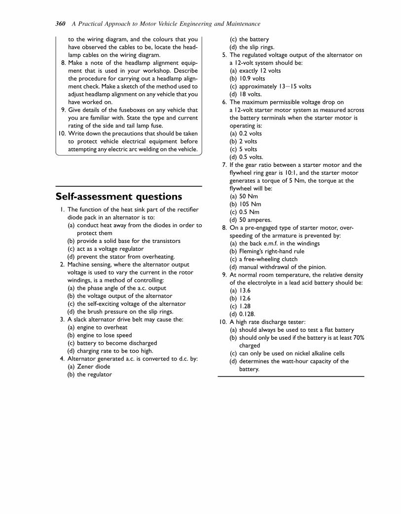
to the wiring diagram, and the colours that youhave observed the cables to be, locate the head-lamp cables on the wiring diagram.
8. Make a note of the headlamp alignment equip-ment that is used in your workshop. Describethe procedure for carrying out a headlamp align-ment check. Make a sketch of the method used toadjust headlamp alignment on any vehicle that youhave worked on.
9. Give details of the fuseboxes on any vehicle thatyou are familiar with. State the type and currentrating of the side and tail lamp fuse.
10. Write down the precautions that should be takento protect vehicle electrical equipment beforeattempting any electric arc welding on the vehicle.
Self-assessment questions1. The function of the heat sink part of the rectifier
diode pack in an alternator is to:(a) conduct heat away from the diodes in order to
protect them(b) provide a solid base for the transistors(c) act as a voltage regulator(d) prevent the stator from overheating.
2. Machine sensing, where the alternator outputvoltage is used to vary the current in the rotorwindings, is a method of controlling:(a) the phase angle of the a.c. output(b) the voltage output of the alternator(c) the self-exciting voltage of the alternator(d) the brush pressure on the slip rings.
3. A slack alternator drive belt may cause the:(a) engine to overheat(b) engine to lose speed(c) battery to become discharged(d) charging rate to be too high.
4. Alternator generated a.c. is converted to d.c. by:(a) Zener diode(b) the regulator
(c) the battery(d) the slip rings.
5. The regulated voltage output of the alternator ona 12-volt system should be:(a) exactly 12 volts(b) 10.9 volts(c) approximately 13e15 volts(d) 18 volts.
6. The maximum permissible voltage drop ona 12-volt starter motor system as measured acrossthe battery terminals when the starter motor isoperating is:(a) 0.2 volts(b) 2 volts(c) 5 volts(d) 0.5 volts.
7. If the gear ratio between a starter motor and theflywheel ring gear is 10:1, and the starter motorgenerates a torque of 5 Nm, the torque at theflywheel will be:(a) 50 Nm(b) 105 Nm(c) 0.5 Nm(d) 50 amperes.
8. On a pre-engaged type of starter motor, over-speeding of the armature is prevented by:(a) the back e.m.f. in the windings(b) Fleming’s right-hand rule(c) a free-wheeling clutch(d) manual withdrawal of the pinion.
9. At normal room temperature, the relative densityof the electrolyte in a lead acid battery should be:(a) 13.6(b) 12.6(c) 1.28(d) 0.128.
10. A high rate discharge tester:(a) should always be used to test a flat battery(b) should only be used if the battery is at least 70%
charged(c) can only be used on nickel alkaline cells(d) determines the watt-hour capacity of the
battery.
360 A Practical Approach to Motor Vehicle Engineering and Maintenance
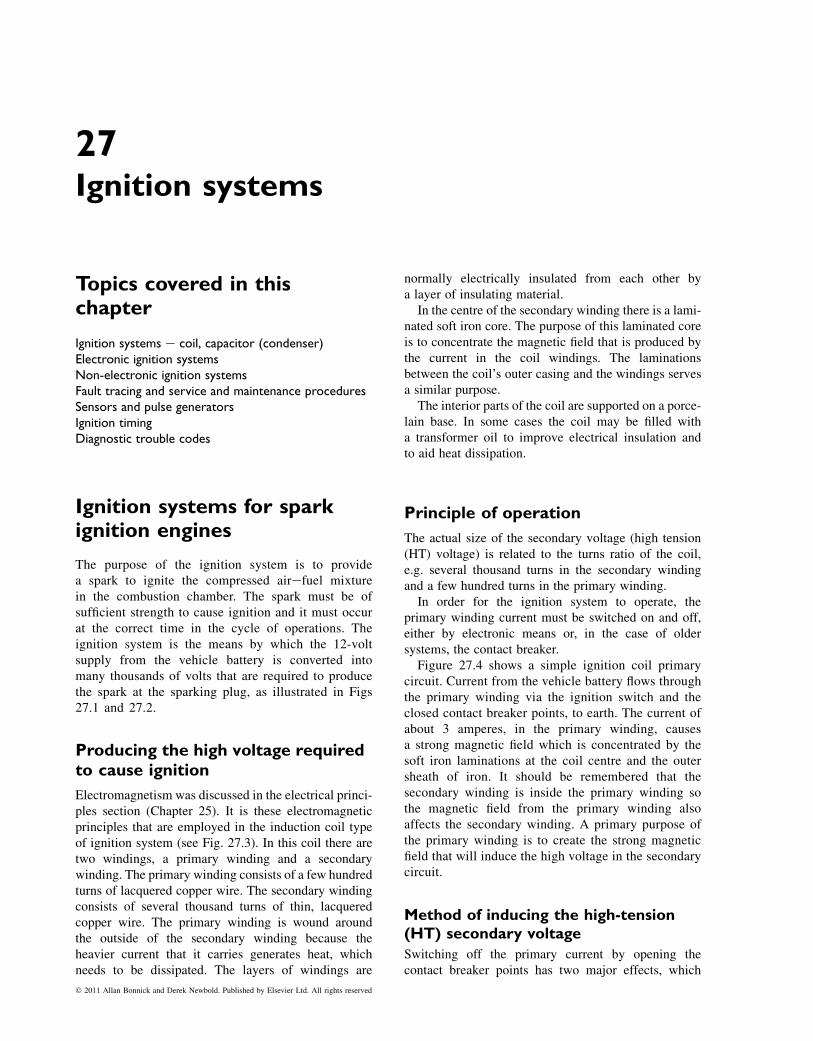
27Ignition systems
Topics covered in thischapter
Ignition systems e coil, capacitor (condenser)Electronic ignition systemsNon-electronic ignition systemsFault tracing and service and maintenance proceduresSensors and pulse generatorsIgnition timingDiagnostic trouble codes
Ignition systems for sparkignition engines
The purpose of the ignition system is to providea spark to ignite the compressed airefuel mixturein the combustion chamber. The spark must be ofsufficient strength to cause ignition and it must occurat the correct time in the cycle of operations. Theignition system is the means by which the 12-voltsupply from the vehicle battery is converted intomany thousands of volts that are required to producethe spark at the sparking plug, as illustrated in Figs27.1 and 27.2.
Producing the high voltage requiredto cause ignition
Electromagnetism was discussed in the electrical princi-ples section (Chapter 25). It is these electromagneticprinciples that are employed in the induction coil typeof ignition system (see Fig. 27.3). In this coil there aretwo windings, a primary winding and a secondarywinding. The primary winding consists of a few hundredturns of lacquered copper wire. The secondary windingconsists of several thousand turns of thin, lacqueredcopper wire. The primary winding is wound aroundthe outside of the secondary winding because theheavier current that it carries generates heat, whichneeds to be dissipated. The layers of windings are
normally electrically insulated from each other bya layer of insulating material.
In the centre of the secondary winding there is a lami-nated soft iron core. The purpose of this laminated coreis to concentrate the magnetic field that is produced bythe current in the coil windings. The laminationsbetween the coil’s outer casing and the windings servesa similar purpose.
The interior parts of the coil are supported on a porce-lain base. In some cases the coil may be filled witha transformer oil to improve electrical insulation andto aid heat dissipation.
Principle of operation
The actual size of the secondary voltage (high tension(HT) voltage) is related to the turns ratio of the coil,e.g. several thousand turns in the secondary windingand a few hundred turns in the primary winding.
In order for the ignition system to operate, theprimary winding current must be switched on and off,either by electronic means or, in the case of oldersystems, the contact breaker.
Figure 27.4 shows a simple ignition coil primarycircuit. Current from the vehicle battery flows throughthe primary winding via the ignition switch and theclosed contact breaker points, to earth. The current ofabout 3 amperes, in the primary winding, causesa strong magnetic field which is concentrated by thesoft iron laminations at the coil centre and the outersheath of iron. It should be remembered that thesecondary winding is inside the primary winding sothe magnetic field from the primary winding alsoaffects the secondary winding. A primary purpose ofthe primary winding is to create the strong magneticfield that will induce the high voltage in the secondarycircuit.
Method of inducing the high-tension(HT) secondary voltage
Switching off the primary current by opening thecontact breaker points has two major effects, which
� 2011 Allan Bonnick and Derek Newbold. Published by Elsevier Ltd. All rights reserved
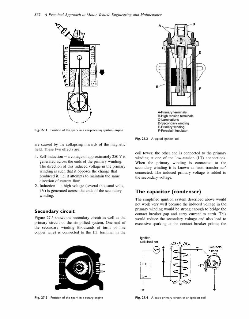
are caused by the collapsing inwards of the magneticfield. These two effects are:
1. Self-induction e a voltage of approximately 250 V isgenerated across the ends of the primary winding.The direction of this induced voltage in the primarywinding is such that it opposes the change thatproduced it, i.e. it attempts to maintain the samedirection of current flow.
2. Induction e a high voltage (several thousand volts,kV) is generated across the ends of the secondarywinding.
Secondary circuit
Figure 27.5 shows the secondary circuit as well as theprimary circuit of the simplified system. One end ofthe secondary winding (thousands of turns of finecopper wire) is connected to the HT terminal in the
coil tower; the other end is connected to the primarywinding at one of the low-tension (LT) connections.When the primary winding is connected to thesecondary winding it is known as ‘auto-transformer’connected. The induced primary voltage is added tothe secondary voltage.
The capacitor (condenser)
The simplified ignition system described above wouldnot work very well because the induced voltage in theprimary winding would be strong enough to bridge thecontact breaker gap and carry current to earth. Thiswould reduce the secondary voltage and also lead toexcessive sparking at the contact breaker points; the
Fig. 27.2 Position of the spark in a rotary engine
Fig. 27.3 A typical ignition coil
Fig. 27.4 A basic primary circuit of an ignition coil
Fig. 27.1 Position of the spark in a reciprocating (piston) engine
362 A Practical Approach to Motor Vehicle Engineering and Maintenance

points would ‘burn’ and the efficiency of the systemwould be seriously impaired. This problem is overcomeby fitting a suitable capacitor (approximately 0.2 mF)across (in parallel with) the points.
Figure 27.6 shows the capacitor in a circuit. Oneterminal of the capacitor is connected to the low-tensionconnection on the distributor and the other terminal isearthed.
Capacitors store electricity so that when, in the caseof the coil ignition system, the contact points begin toopen, the self-induced current from the primary windingwill flow into the capacitor instead of ‘jumping’ acrossthe points gap. This flow of current will continue untilthe capacitor is fully charged. When the capacitor isfully charged it will automatically discharge itself,back into the primary winding. This capacitor dischargecurrent is in the opposite direction to the original flowand it helps to cause a rapid collapse of the magneticfield. This, in turn, leads to a much higher HT voltagefrom the secondary winding.
Coil polarity
Electrons flow from negative to positive and thermalactivity (heat) also aids electron generation; for this
reason the insulated (central) hotter electrode of thespark plug is made negative in relation to the HTwinding as shown in Fig. 27.7. The result of this polaritydirection is that a lower voltage is required to generatea spark across the plug gap. To ensure that the correctcoil polarity is maintained, the LT connections on thecoil are normally marked as 1 and 2.
The coil polarity is readily checked by means of thenormal garage-type oscilloscope. Figure 27.8 showsthe inverted waveform that results from incorrectconnection of the coil, or the fitting of the wrong typeof coil for the vehicle under test.
Electronic ignition systems
Electronic ignition systems make use of some form ofelectrical/electronic device to produce the electricalpulse that switches ‘on and off’ the ignition coil primarycurrent so that a high voltage is induced in the coilsecondary winding in order to produce a spark, in therequired cylinder, at the correct time.
There are several methods of producing the ‘trig-gering’ pulse for the ignition that replaces the ‘on andoff’ action of the contact breaker. The commonly usedtypes are reviewed in the following sections.
Fig. 27.5 The secondary and primary circuits of a coil
Fig. 27.6 The ignition circuit with the capacitor in place
Fig. 27.7 Polarity of spark plug electrodes
Fig. 27.8 The inverted waveform on the oscilloscope screen
Ignition systems 363
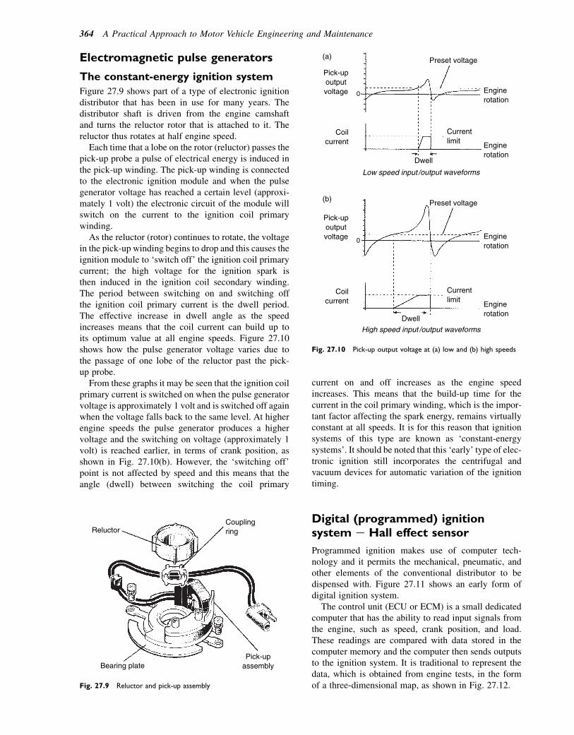
Electromagnetic pulse generators
The constant-energy ignition system
Figure 27.9 shows part of a type of electronic ignitiondistributor that has been in use for many years. Thedistributor shaft is driven from the engine camshaftand turns the reluctor rotor that is attached to it. Thereluctor thus rotates at half engine speed.
Each time that a lobe on the rotor (reluctor) passes thepick-up probe a pulse of electrical energy is induced inthe pick-up winding. The pick-up winding is connectedto the electronic ignition module and when the pulsegenerator voltage has reached a certain level (approxi-mately 1 volt) the electronic circuit of the module willswitch on the current to the ignition coil primarywinding.
As the reluctor (rotor) continues to rotate, the voltagein the pick-up winding begins to drop and this causes theignition module to ‘switch off’ the ignition coil primarycurrent; the high voltage for the ignition spark isthen induced in the ignition coil secondary winding.The period between switching on and switching offthe ignition coil primary current is the dwell period.The effective increase in dwell angle as the speedincreases means that the coil current can build up toits optimum value at all engine speeds. Figure 27.10shows how the pulse generator voltage varies due tothe passage of one lobe of the reluctor past the pick-up probe.
From these graphs it may be seen that the ignition coilprimary current is switched on when the pulse generatorvoltage is approximately 1 volt and is switched off againwhen the voltage falls back to the same level. At higherengine speeds the pulse generator produces a highervoltage and the switching on voltage (approximately 1volt) is reached earlier, in terms of crank position, asshown in Fig. 27.10(b). However, the ‘switching off’point is not affected by speed and this means that theangle (dwell) between switching the coil primary
current on and off increases as the engine speedincreases. This means that the build-up time for thecurrent in the coil primary winding, which is the impor-tant factor affecting the spark energy, remains virtuallyconstant at all speeds. It is for this reason that ignitionsystems of this type are known as ‘constant-energysystems’. It should be noted that this ‘early’ type of elec-tronic ignition still incorporates the centrifugal andvacuum devices for automatic variation of the ignitiontiming.
Digital (programmed) ignitionsystem e Hall effect sensor
Programmed ignition makes use of computer tech-nology and it permits the mechanical, pneumatic, andother elements of the conventional distributor to bedispensed with. Figure 27.11 shows an early form ofdigital ignition system.
The control unit (ECU or ECM) is a small dedicatedcomputer that has the ability to read input signals fromthe engine, such as speed, crank position, and load.These readings are compared with data stored in thecomputer memory and the computer then sends outputsto the ignition system. It is traditional to represent thedata, which is obtained from engine tests, in the formof a three-dimensional map, as shown in Fig. 27.12.
Bearing plate Pick-up
assembly
Reluctor Coupling ring
Fig. 27.9 Reluctor and pick-up assembly
High speed input /output waveforms
Preset voltage
Preset voltage
Engine rotation
Engine rotation
Engine rotation
Engine rotation
Current limit
Current limit
Dwell
Dwell
Low speed input /output waveforms
Coil current
Coil current
Pick-up output voltage 0
0
Pick-up output voltage
(a)
(b)
Fig. 27.10 Pick-up output voltage at (a) low and (b) high speeds
364 A Practical Approach to Motor Vehicle Engineering and Maintenance
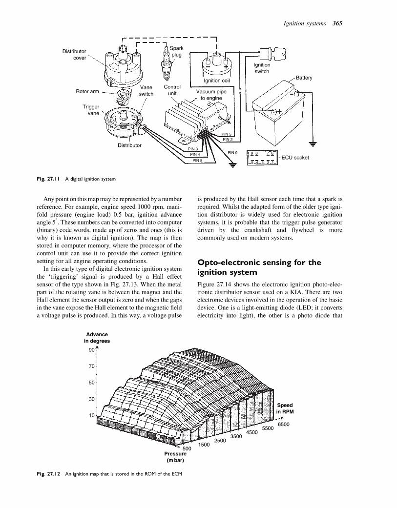
Anypoint on thismapmay be represented by a numberreference. For example, engine speed 1000 rpm, mani-fold pressure (engine load) 0.5 bar, ignition advanceangle 58. These numbers can be converted into computer(binary) code words, made up of zeros and ones (this iswhy it is known as digital ignition). The map is thenstored in computer memory, where the processor of thecontrol unit can use it to provide the correct ignitionsetting for all engine operating conditions.
In this early type of digital electronic ignition systemthe ‘triggering’ signal is produced by a Hall effectsensor of the type shown in Fig. 27.13. When the metalpart of the rotating vane is between the magnet and theHall element the sensor output is zero and when the gapsin the vane expose the Hall element to the magnetic fielda voltage pulse is produced. In this way, a voltage pulse
is produced by the Hall sensor each time that a spark isrequired. Whilst the adapted form of the older type igni-tion distributor is widely used for electronic ignitionsystems, it is probable that the trigger pulse generatordriven by the crankshaft and flywheel is morecommonly used on modern systems.
Opto-electronic sensing for theignition system
Figure 27.14 shows the electronic ignition photo-elec-tronic distributor sensor used on a KIA. There are twoelectronic devices involved in the operation of the basicdevice. One is a light-emitting diode (LED; it convertselectricity into light), the other is a photo diode that
Distributor cover
Rotor arm Vane switch
Control unit Vacuum pipe
to engine
Spark plug
Ignition coil
Ignition switch
Battery
ECU socket
PIN 5 PIN 2
PIN 9 9 8 7 6
1 2 3 4 5 PIN 8
PIN 4 PIN 3
Trigger vane
Distributor
Fig. 27.11 A digital ignition system
Advance in degrees
500 1500
2500 3500
4500 5500
6500
Speed in RPM
Pressure (m bar)
90
70
50
30
10
Fig. 27.12 An ignition map that is stored in the ROM of the ECM
Ignition systems 365
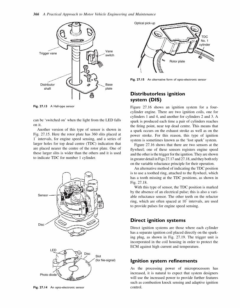
can be ‘switched on’ when the light from the LED fallson it.
Another version of this type of sensor is shown inFig. 27.15. Here the rotor plate has 360 slits placed at18 intervals, for engine speed sensing, and a series oflarger holes for top dead centre (TDC) indication thatare placed nearer the centre of the rotor plate. One ofthese larger slits is wider than the others and it is usedto indicate TDC for number 1 cylinder.
Distributorless ignitionsystem (DIS)
Figure 27.16 shows an ignition system for a four-cylinder engine. There are two ignition coils, one forcylinders 1 and 4, and another for cylinders 2 and 3. Aspark is produced each time a pair of cylinders reachesthe firing point, near top dead centre. This means thata spark occurs on the exhaust stroke as well as on thepower stroke. For this reason, this type of ignitionsystem is sometimes known as the ‘lost spark’ system.
Figure 27.16 shows that there are two sensors at theflywheel; one of these sensors registers engine speedand the other is the trigger for the ignition. They are shownin greater detail in Figs 27.17 and 27.18, and they both relyon the variable reluctance principle for their operation.
An alternative method of indicating the TDC positionis to use a toothed ring, attached to the flywheel, whichhas a tooth missing at the TDC positions, as shown inFig. 27.18.
With this type of sensor, the TDC position is markedby the absence of an electrical pulse; this is also a vari-able reluctance sensor. The other teeth on the reluctorring, which are often spaced at 108 intervals, are usedto provide pulses for engine speed sensing.
Direct ignition systems
Direct ignition systems are those where each cylinderhas a separate ignition coil placed directly on the spark-ing plug, as shown in Fig. 27.19. The trigger unit isincorporated in the coil housing in order to protect theECM against high current and temperature.
Ignition system refinements
As the processing power of microprocessors hasincreased, it is natural to expect that system designerswill use the increased power to provide further featuressuch as combustion knock sensing and adaptive ignitioncontrol.
Trigger vane
Distributor shaft
Base plate
Vane switch
Fig. 27.13 A Hall-type sensor
Sensor
Disc
LED
Photo diode
Disc Slot (for Ne-signal)
Fig. 27.14 An opto-electronic sensor
Optical pick-up
Rotor plate
TDC No. 1
cylinder
Fig. 27.15 An alternative form of opto-electronic sensor
366 A Practical Approach to Motor Vehicle Engineering and Maintenance

Knock sensing
Combustion knock is a problem that is associated withengine operation. Early motor vehicles were equippedwith a hand control that enabled the driver to retardthe ignition when the characteristic ‘pinking’ soundwas heard. After the pinking had ceased the driver couldmove the control lever back to the advanced position.Electronic controls permit this process to be done auto-matically and a knock sensor is often included in themake-up of an electronic ignition system.
Combustion knock sensors
A knock sensor that is commonly used in engine controlsystems utilizes the piezo-electric generator effect. Thatis, the sensing element produces a small electric chargewhen it is compressed and then relaxed. Materials such
as quartz and some ceramics like PZT (a mixture of plat-inum, zirconium, and titanium) are effective in piezo-electric applications. In the application shown inFig. 27.20, the knock sensor is located on the engineblock adjacent to cylinder number 3. In this position itis best able to detect vibrations arising from combustionknock in any of the four cylinders.
Because combustion knock is most likely to occurclose to top dead centre in any cylinder, the controlprogram held in the ECMmemory enables the processorto use any knock signal generated to alter the ignitiontiming by an amount that is sufficient to eliminatethe knock. When knock has ceased the ECM willadvance the ignition, in steps, back to its normalsetting. The mechanism by which vibrations arisingfrom knock are converted to electricity is illustrated inFig. 27.21.
The sensor is accurately designed and the centre boltthat pre-tensions the piezo-electric crystal is accurately
Engine load (vacuum)
ECU
Engine speed sensor
+
−
Engine position sensor
Engine flywheel
Ring gear teeth
Twin double ended coils
Plug gaps
Plug gaps
Fig. 27.16 Distributorless ignition system
TDC peg
TDC sensor
Flywheel ring gear
Soft iron core
Winding
Engine speed sensor Permanent
magnet
Fig. 27.17 Details of engine speed and crank position sensor
Toothed wheel
Missing teeth
Crankshaft sensor
Fig. 27.18 Engine speed and position sensor that uses a detachable
reluctor ring
Ignition systems 367
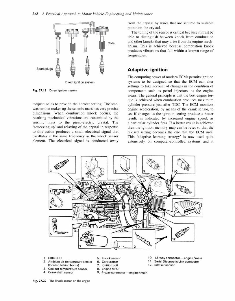
torqued so as to provide the correct setting. The steelwasher that makes up the seismic mass has very precisedimensions. When combustion knock occurs, theresulting mechanical vibrations are transmitted by theseismic mass to the piezo-electric crystal. The‘squeezing up’ and relaxing of the crystal in responseto this action produces a small electrical signal thatoscillates at the same frequency as the knock sensorelement. The electrical signal is conducted away
from the crystal by wires that are secured to suitablepoints on the crystal.
The tuning of the sensor is critical because it must beable to distinguish between knock from combustionand other knocks that may arise from the engine mech-anism. This is achieved because combustion knockproduces vibrations that fall within a known range offrequencies.
Adaptive ignition
The computing power of modern ECMs permits ignitionsystems to be designed so that the ECM can altersettings to take account of changes in the condition ofcomponents such as petrol injectors, as the enginewears. The general principle is that the best engine tor-que is achieved when combustion produces maximumcylinder pressure just after TDC. The ECM monitorsengine acceleration, by means of the crank sensor, tosee if changes to the ignition setting produce a betterresult, as indicated by increased engine speed, asa particular cylinder fires. If a better result is achievedthen the ignition memory map can be reset so that therevised setting becomes the one that the ECM uses.This ‘adaptive learning strategy’ is now used quiteextensively on computer-controlled systems and it
Coils
Spark plugs
Direct ignition system
Fig. 27.19 Direct ignition system
Fig. 27.20 The knock sensor on the engine
368 A Practical Approach to Motor Vehicle Engineering and Maintenance

requires technicians to run vehicles under normaldriving conditions for several minutes after replacementparts and adjustments have been made to a vehicle.
Fault tracing, maintenance,and repair of ignition systems
The majority of the following descriptions are basedon the use of a portable oscilloscope. However, for testson the primary circuit of an ignition system, a good-quality digital multimeter will also serve mostpurposes.
Performance checks on pulsegenerators
If preliminary tests on the ignition circuit indicate thatthe pulse generator may be defective, checks of thefollowing type can provide useful information.
Magnetic (inductive)-type ignition pulsegenerator
The voltage output of a typical ignition pulse generatorof this type varies with engine speed and the actualvoltage varies considerably according to manufacturer.However, the voltage waveform is of similar form formost makes and useful test information can be gainedfrom a voltage test. There are two possible states fora voltage test: one is with the pulse generator discon-nected from the electronic module when a waveformof the type shown in Fig. 27.22 should be produced,and the other is when the pulse generator is connectedto the electronic module, when the waveform shownin Fig. 27.23 should be produced. The difference isaccounted for by the fact that the lower part of the
pattern is affected by the loading from the electronicmodule.
A digital voltmeter set to an appropriate a.c. rangemay also be used to check the output of this type ofpulse generator. The voltages for each pulse should beidentical and the maximum value should be at the levelgiven in the vehicle repair data.
Body of the sensor is
screwed into the cylinder
block
Electrical connections
+ and –
–
Steel washer makes the seismic mass
Accurately torqued bolt
Piezo-electriccrystalelement
Fig. 27.21 The principle of the piezo-electric combustion knock sensor
Spez
20 V
412191
tz
Fig. 27.22 Waveform, pulse generator e electronic module
disconnected
Spez
20 V
412192
tz
Fig. 27.23 Waveform, pulse generator e electronic module
connected
Ignition systems 369
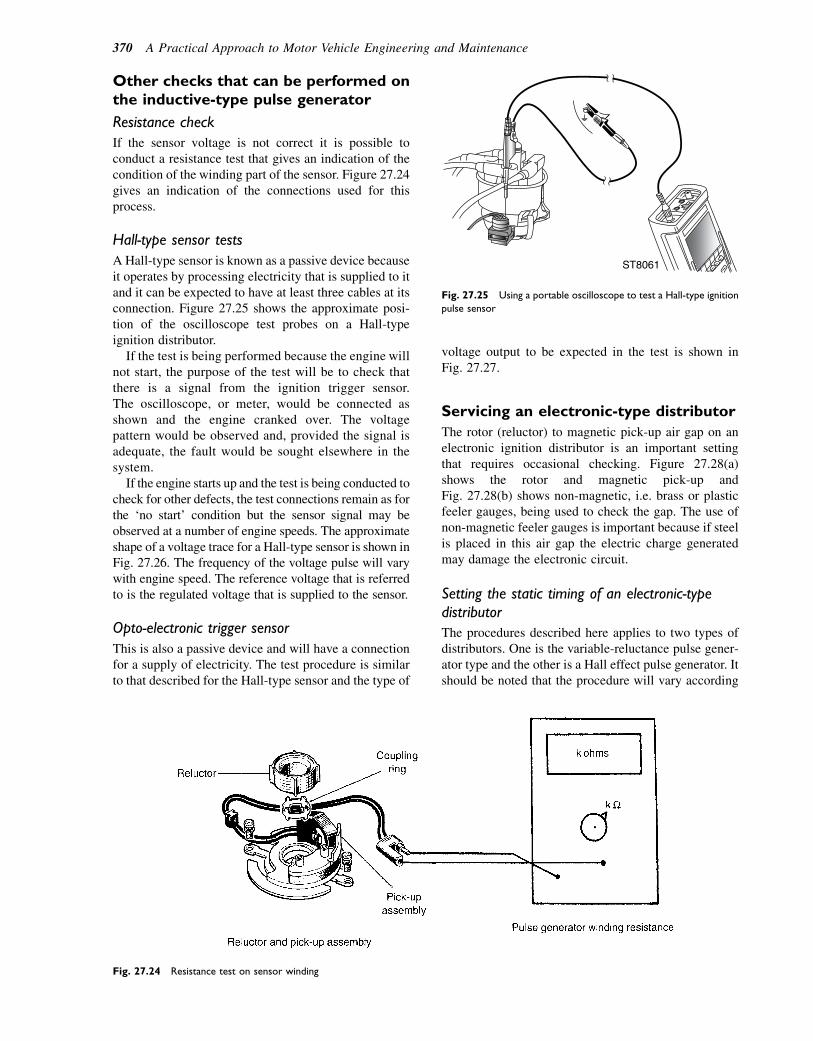
Other checks that can be performed onthe inductive-type pulse generator
Resistance check
If the sensor voltage is not correct it is possible toconduct a resistance test that gives an indication of thecondition of the winding part of the sensor. Figure 27.24gives an indication of the connections used for thisprocess.
Hall-type sensor tests
A Hall-type sensor is known as a passive device becauseit operates by processing electricity that is supplied to itand it can be expected to have at least three cables at itsconnection. Figure 27.25 shows the approximate posi-tion of the oscilloscope test probes on a Hall-typeignition distributor.
If the test is being performed because the engine willnot start, the purpose of the test will be to check thatthere is a signal from the ignition trigger sensor.The oscilloscope, or meter, would be connected asshown and the engine cranked over. The voltagepattern would be observed and, provided the signal isadequate, the fault would be sought elsewhere in thesystem.
If the engine starts up and the test is being conducted tocheck for other defects, the test connections remain as forthe ‘no start’ condition but the sensor signal may beobserved at a number of engine speeds. The approximateshape of a voltage trace for a Hall-type sensor is shown inFig. 27.26. The frequency of the voltage pulse will varywith engine speed. The reference voltage that is referredto is the regulated voltage that is supplied to the sensor.
Opto-electronic trigger sensor
This is also a passive device and will have a connectionfor a supply of electricity. The test procedure is similarto that described for the Hall-type sensor and the type of
voltage output to be expected in the test is shown inFig. 27.27.
Servicing an electronic-type distributor
The rotor (reluctor) to magnetic pick-up air gap on anelectronic ignition distributor is an important settingthat requires occasional checking. Figure 27.28(a)shows the rotor and magnetic pick-up andFig. 27.28(b) shows non-magnetic, i.e. brass or plasticfeeler gauges, being used to check the gap. The use ofnon-magnetic feeler gauges is important because if steelis placed in this air gap the electric charge generatedmay damage the electronic circuit.
Setting the static timing of an electronic-typedistributor
The procedures described here applies to two types ofdistributors. One is the variable-reluctance pulse gener-ator type and the other is a Hall effect pulse generator. Itshould be noted that the procedure will vary according
Fig. 27.24 Resistance test on sensor winding
ST8061
Fig. 27.25 Using a portable oscilloscope to test a Hall-type ignition
pulse sensor
370 A Practical Approach to Motor Vehicle Engineering and Maintenance
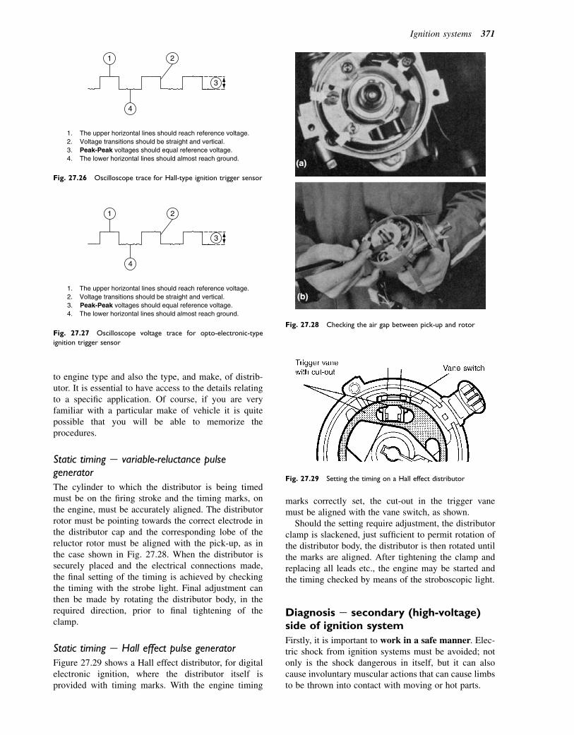
to engine type and also the type, and make, of distrib-utor. It is essential to have access to the details relatingto a specific application. Of course, if you are veryfamiliar with a particular make of vehicle it is quitepossible that you will be able to memorize theprocedures.
Static timing e variable-reluctance pulsegenerator
The cylinder to which the distributor is being timedmust be on the firing stroke and the timing marks, onthe engine, must be accurately aligned. The distributorrotor must be pointing towards the correct electrode inthe distributor cap and the corresponding lobe of thereluctor rotor must be aligned with the pick-up, as inthe case shown in Fig. 27.28. When the distributor issecurely placed and the electrical connections made,the final setting of the timing is achieved by checkingthe timing with the strobe light. Final adjustment canthen be made by rotating the distributor body, in therequired direction, prior to final tightening of theclamp.
Static timing e Hall effect pulse generator
Figure 27.29 shows a Hall effect distributor, for digitalelectronic ignition, where the distributor itself isprovided with timing marks. With the engine timing
marks correctly set, the cut-out in the trigger vanemust be aligned with the vane switch, as shown.
Should the setting require adjustment, the distributorclamp is slackened, just sufficient to permit rotation ofthe distributor body, the distributor is then rotated untilthe marks are aligned. After tightening the clamp andreplacing all leads etc., the engine may be started andthe timing checked by means of the stroboscopic light.
Diagnosis e secondary (high-voltage)side of ignition system
Firstly, it is important to work in a safe manner. Elec-tric shock from ignition systems must be avoided; notonly is the shock dangerous in itself, but it can alsocause involuntary muscular actions that can cause limbsto be thrown into contact with moving or hot parts.
1. The upper horizontal lines should reach reference voltage.2. Voltage transitions should be straight and vertical.3. Peak-Peak voltages should equal reference voltage.4. The lower horizontal lines should almost reach ground.
1 2
3
4
Fig. 27.26 Oscilloscope trace for Hall-type ignition trigger sensor
1. The upper horizontal lines should reach reference voltage.2. Voltage transitions should be straight and vertical.3. Peak-Peak voltages should equal reference voltage.4. The lower horizontal lines should almost reach ground.
1 2
3
4
Fig. 27.27 Oscilloscope voltage trace for opto-electronic-type
ignition trigger sensor
Fig. 27.28 Checking the air gap between pick-up and rotor
Fig. 27.29 Setting the timing on a Hall effect distributor
Ignition systems 371

Tests on distributor-type ignitionsystems
The king lead and the HT lead to number 1 cylinder arenormally connected to the oscilloscope as shown inFig. 27.30. A typical oscilloscope display for a distrib-utor-type ignition is shown in Fig. 27.31. These displaysshow the firing voltage for number 1 cylinder. Theparade pattern shows the voltage of the remaining cylin-ders as displayed across the screen, in firing order, fromleft to right.
Tests on distributorless ignition systems
In this case there is no king lead so the inductive pick-upis clamped to the HT leads individually, as close aspossible to the spark plug, as shown in Fig. 27.32. Thescreen display obtained from such a test shows dataabout engine speed, burn time, and voltage. These andother details may more easily be seen by taking anenlargement of the trace for a single cylinder, as shownin Fig. 27.33.
The details are:
1. Firing line. This represents the high voltage neededto cause the spark to bridge the plug gap.
2. The spark line.3. Spark ceases.4. Coil oscillations.
5. Intermediate section (any remaining energy isdissipated prior to the next spark).
6. Firing section (represents burn time).7. Dwell section.8. Primary winding current is interrupted by transistor
controlled by the ECM.9. Primary winding current is switched on to energize
the primary. The dwell period is important becauseof the time required for the current to reach itsmaximum value.
A comparison of the secondary voltage traces foreach of the cylinders should show them to be broadlysimilar. If there are major differences between thepatterns then it is an indication of a defect.
For example, a low firing voltage (1) indicates lowresistance in the HT cable or at the spark plug. Thelow resistance could be attributed to several factors,including oil or carbon fouled spark plug, incorrectplug gap, low cylinder pressure, or defective HT cable.A high voltage at (1) indicates high resistance in the HTcable, or at the spark plug. Factors to consider hereinclude a loose HT lead, wide plug gap, or an excessiveamount of resistance has developed in the HT cable.Table 27.1 summarizes the major points.
STAO10BO
Fig. 27.30 Oscilloscope connections for obtaining ignition trace
Fig. 27.31 Oscilloscope displays of secondary ignition voltage e
single pattern and parade
Fig. 27.32 The oscilloscope set-up for obtaining a secondary
voltage trace from a DIS
Fig. 27.33 Details of the HT voltage trace for a single cylinder
372 A Practical Approach to Motor Vehicle Engineering and Maintenance
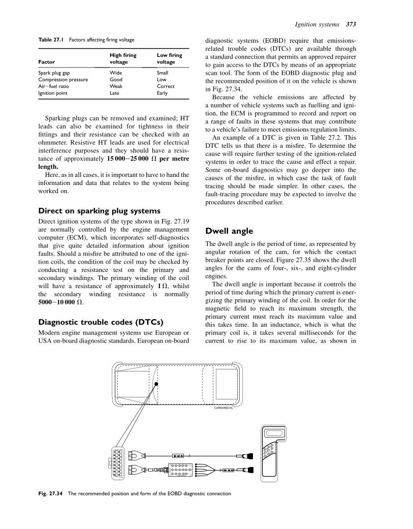
Sparking plugs can be removed and examined; HTleads can also be examined for tightness in theirfittings and their resistance can be checked with anohmmeter. Resistive HT leads are used for electricalinterference purposes and they should have a resis-tance of approximately 15 000e25 000 V per metrelength.
Here, as in all cases, it is important to have to hand theinformation and data that relates to the system beingworked on.
Direct on sparking plug systems
Direct ignition systems of the type shown in Fig. 27.19are normally controlled by the engine managementcomputer (ECM), which incorporates self-diagnosticsthat give quite detailed information about ignitionfaults. Should a misfire be attributed to one of the igni-tion coils, the condition of the coil may be checked byconducting a resistance test on the primary andsecondary windings. The primary winding of the coilwill have a resistance of approximately 1V, whilstthe secondary winding resistance is normally5000e10 000 V.
Diagnostic trouble codes (DTCs)
Modern engine management systems use European orUSA on-board diagnostic standards. European on-board
diagnostic systems (EOBD) require that emissions-related trouble codes (DTCs) are available througha standard connection that permits an approved repairerto gain access to the DTCs by means of an appropriatescan tool. The form of the EOBD diagnostic plug andthe recommended position of it on the vehicle is shownin Fig. 27.34.
Because the vehicle emissions are affected bya number of vehicle systems such as fuelling and igni-tion, the ECM is programmed to record and report ona range of faults in these systems that may contributeto a vehicle’s failure to meet emissions regulation limits.
An example of a DTC is given in Table 27.2. ThisDTC tells us that there is a misfire. To determine thecause will require further testing of the ignition-relatedsystems in order to trace the cause and effect a repair.Some on-board diagnostics may go deeper into thecauses of the misfire, in which case the task of faulttracing should be made simpler. In other cases, thefault-tracing procedure may be expected to involve theprocedures described earlier.
Dwell angle
The dwell angle is the period of time, as represented byangular rotation of the cam, for which the contactbreaker points are closed. Figure 27.35 shows the dwellangles for the cams of four-, six-, and eight-cylinderengines.
The dwell angle is important because it controls theperiod of time during which the primary current is ener-gizing the primary winding of the coil. In order for themagnetic field to reach its maximum strength, theprimary current must reach its maximum value andthis takes time. In an inductance, which is what theprimary coil is, it takes several milliseconds for thecurrent to rise to its maximum value, as shown in
Table 27.1 Factors affecting firing voltage
Factor
High firing
voltage
Low firing
voltage
Spark plug gap Wide Small
Compression pressure Good Low
Airefuel ratio Weak Correct
Ignition point Late Early
Fig. 27.34 The recommended position and form of the EOBD diagnostic connection
Ignition systems 373
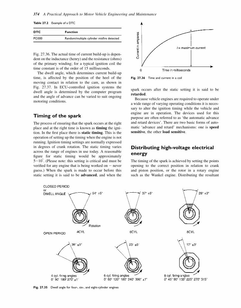
Fig. 27.36. The actual time of current build-up is depen-dent on the inductance (henry) and the resistance (ohms)of the primary winding; for a typical ignition coil thetime constant is of the order of 15 milliseconds.
The dwell angle, which determines current build-uptime, is affected by the position of the heel of themoving contact in relation to the cam, as shown inFig. 27.37. In ECU-controlled ignition systems thedwell angle is determined by the computer programand the angle of advance can be varied to suit ongoingmotoring conditions.
Timing of the spark
The process of ensuring that the spark occurs at the rightplace and at the right time is known as timing the igni-tion. In the first place there is static timing. This is theoperation of setting up the timing when the engine is notrunning. Ignition timing settings are normally expressedin degrees of crank rotation. The static timing variesacross the range of engines in use today. A reasonablefigure for static timing would be approximately5e108. (Please note: this setting is critical and must beverified for any engine that is being worked on e neverguess.) When the spark is made to occur before thisstatic setting it is said to be advanced, and when the
spark occurs after the static setting it is said to beretarded.
Because vehicle engines are required to operate undera wide range of varying operating conditions it is neces-sary to alter the ignition timing while the vehicle andengine are in operation. The devices used for thispurpose are often referred to as ‘the automatic advanceand retard devices’. There are two basic forms of auto-matic ‘advance and retard’ mechanisms: one is speedsensitive, the other load sensitive.
Distributing high-voltage electricalenergy
The timing of the spark is achieved by setting the pointsopening to the correct position in relation to crankand piston position, or the rotor in a rotary enginesuch as the Wankel engine. Distributing the resultant
Table 27.2 Example of a DTC
DTC Function
PO300 Random/multiple cylinder misfire detected
Fig. 27.35 Dwell angle for four-, six-, and eight-cylinder engines
Fig. 27.36 Time and current in a coil
374 A Practical Approach to Motor Vehicle Engineering and Maintenance
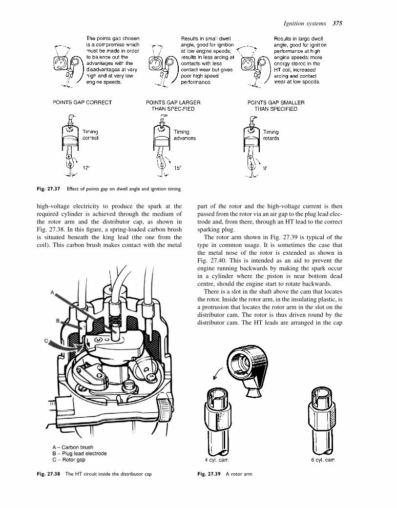
high-voltage electricity to produce the spark at therequired cylinder is achieved through the medium ofthe rotor arm and the distributor cap, as shown inFig. 27.38. In this figure, a spring-loaded carbon brushis situated beneath the king lead (the one from thecoil). This carbon brush makes contact with the metal
part of the rotor and the high-voltage current is thenpassed from the rotor via an air gap to the plug lead elec-trode and, from there, through an HT lead to the correctsparking plug.
The rotor arm shown in Fig. 27.39 is typical of thetype in common usage. It is sometimes the case thatthe metal nose of the rotor is extended as shown inFig. 27.40. This is intended as an aid to prevent theengine running backwards by making the spark occurin a cylinder where the piston is near bottom deadcentre, should the engine start to rotate backwards.
There is a slot in the shaft above the cam that locatesthe rotor. Inside the rotor arm, in the insulating plastic, isa protrusion that locates the rotor arm in the slot on thedistributor cam. The rotor is thus driven round by thedistributor cam. The HT leads are arranged in the cap
Fig. 27.37 Effect of points gap on dwell angle and ignition timing
Fig. 27.38 The HT circuit inside the distributor cap Fig. 27.39 A rotor arm
Ignition systems 375
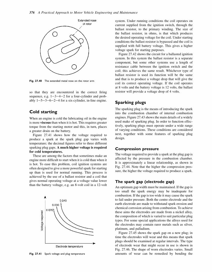
so that they are encountered in the correct firingsequence, e.g. 1e3e4e2 for a four-cylinder and prob-ably 1e5e3e6e2e4 for a six-cylinder, in-line engine.
Cold starting
When an engine is cold the lubricating oil in the engineis more viscous than when it is hot. This requires greatertorque from the starting motor and this, in turn, placesa greater drain on the battery.
Figure 27.41 shows how the voltage required toproduce a spark at the spark plug gap varies withtemperature; the decimal figures refer to three differentsparking plug gaps. Amuch higher voltage is requiredfor cold temperatures.
These are among the factors that sometimes make anengine more difficult to start when it is cold than when itis hot. To ease this problem, coil ignition systems areoften designed to give a more powerful spark for startingup than is used for normal running. This process isachieved by the use of a ballast resistor and a coil thatgives normal operating voltage at a voltage value lowerthan the battery voltage, e.g. an 8-volt coil in a 12-volt
system. Under running conditions the coil operates oncurrent supplied from the ignition switch, through theballast resistor, to the primary winding. The size ofthe ballast resistor, in ohms, is that which producesthe desired operating voltage for the coil. Under startingconditions the ballast resistor is bypassed and the coil issupplied with full battery voltage. This gives a highervoltage spark for starting purposes.
Figure 27.42 shows the circuit for a ballasted ignitionsystem. In this system the ballast resistor is a separatecomponent, but some other systems use a length ofresistance cable between the ignition switch and thecoil; this achieves the same result. Whichever type ofballast resistor is used its function will be the sameand that is to produce a voltage drop that will give thecoil its correct operating voltage. If the coil operatesat 8 volts and the battery voltage is 12 volts, the ballastresistor will provide a voltage drop of 4 volts.
Sparking plugs
The sparking plug is the means of introducing the sparkinto the combustion chamber of internal combustionengines. Figure 27.43 shows the main details of a widelyused make of sparking plug. In order to function effec-tively, sparking plugs must operate under a wide rangeof varying conditions. These conditions are considerednext, together with some features of sparking plugdesign.
Compression pressure
The voltage required to provide a spark at the plug gap isaffected by the pressure in the combustion chamber.It is approximately a linear relationship, as shown inFig. 27.44. Note that the higher the compression pres-sure, the higher the voltage required to produce a spark.
The spark gap (electrode gap)
An optimum gap width must be maintained. If the gap istoo small the spark energy may be inadequate forcombustion. If the gap is too wide it may cause the sparkto fail under pressure. Both the centre electrode and theearth electrode are made to withstand spark erosion andchemical corrosion arising from combustion. To achievethese aims the electrodes are made from a nickel alloy,the composition of which is varied to suit particular plugtypes. For some special applications the alloys used forthe electrodes may contain rarer metals such as silver,platinum, and palladium.
Figure 27.45 shows the spark gap on a new plug; intime the electrodes will wear and this means that sparkplugs should be examined at regular intervals. The typeof electrode wear that might occur in use is shown inFig. 27.46. The shape of worn electrodes varies. Smallamounts of wear can be remedied by bending the
Fig. 27.40 The extended metal nose on the rotor arm
Fig. 27.41 Spark voltage and plug temperature
376 A Practical Approach to Motor Vehicle Engineering and Maintenance
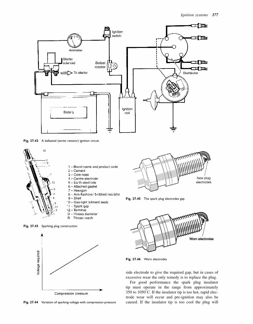
side electrode to give the required gap, but in cases ofexcessive wear the only remedy is to replace the plug.
For good performance the spark plug insulatortip must operate in the range from approximately350 to 10508C. If the insulator tip is too hot, rapid elec-trode wear will occur and pre-ignition may also becaused. If the insulator tip is too cool the plug will
Fig. 27.42 A ballasted (series resistor) ignition circuit
Fig. 27.43 Sparking plug construction
Fig. 27.44 Variation of sparking voltage with compression pressure
Fig. 27.45 The spark plug electrodes gap
Fig. 27.46 Worn electrodes
Ignition systems 377
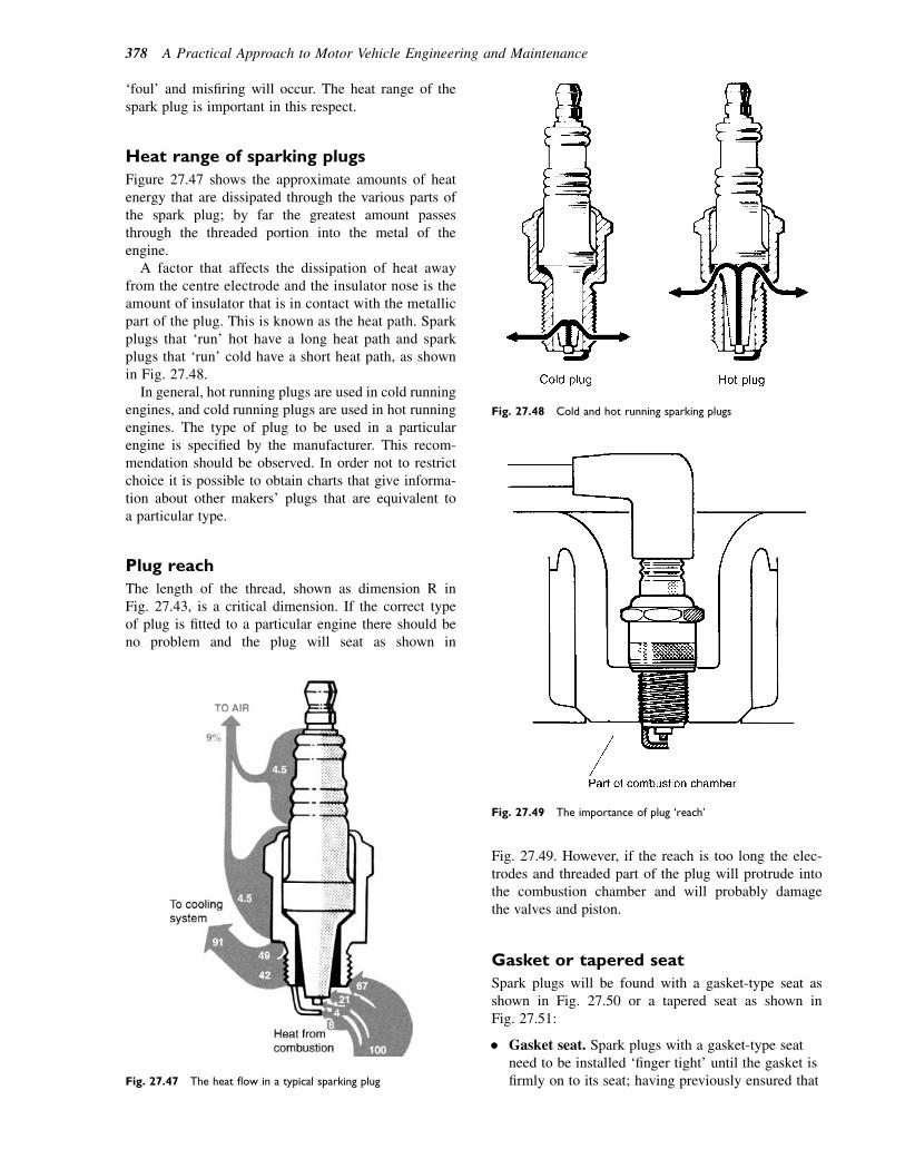
‘foul’ and misfiring will occur. The heat range of thespark plug is important in this respect.
Heat range of sparking plugs
Figure 27.47 shows the approximate amounts of heatenergy that are dissipated through the various parts ofthe spark plug; by far the greatest amount passesthrough the threaded portion into the metal of theengine.
A factor that affects the dissipation of heat awayfrom the centre electrode and the insulator nose is theamount of insulator that is in contact with the metallicpart of the plug. This is known as the heat path. Sparkplugs that ‘run’ hot have a long heat path and sparkplugs that ‘run’ cold have a short heat path, as shownin Fig. 27.48.
In general, hot running plugs are used in cold runningengines, and cold running plugs are used in hot runningengines. The type of plug to be used in a particularengine is specified by the manufacturer. This recom-mendation should be observed. In order not to restrictchoice it is possible to obtain charts that give informa-tion about other makers’ plugs that are equivalent toa particular type.
Plug reach
The length of the thread, shown as dimension R inFig. 27.43, is a critical dimension. If the correct typeof plug is fitted to a particular engine there should beno problem and the plug will seat as shown in
Fig. 27.49. However, if the reach is too long the elec-trodes and threaded part of the plug will protrude intothe combustion chamber and will probably damagethe valves and piston.
Gasket or tapered seat
Spark plugs will be found with a gasket-type seat asshown in Fig. 27.50 or a tapered seat as shown inFig. 27.51:
� Gasket seat. Spark plugs with a gasket-type seatneed to be installed ‘finger tight’ until the gasket isfirmly on to its seat; having previously ensured thatFig. 27.47 The heat flow in a typical sparking plug
Fig. 27.48 Cold and hot running sparking plugs
Fig. 27.49 The importance of plug ‘reach’
378 A Practical Approach to Motor Vehicle Engineering and Maintenance
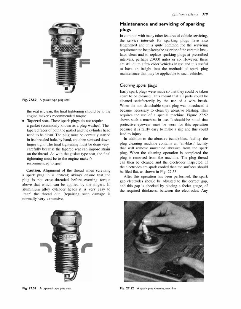
the seat is clean, the final tightening should be to theengine maker’s recommended torque.
� Tapered seat. These spark plugs do not requirea gasket (commonly known as a plug washer). Thetapered faces of both the gasket and the cylinder headneed to be clean. The plug must be correctly startedin its threaded hole, by hand, and then screwed down,finger tight. The final tightening must be done verycarefully because the tapered seat can impose strainon the thread. As with the gasket-type seat, the finaltightening must be to the engine maker’srecommended torque.
Caution. Alignment of the thread when screwinga spark plug in is critical; always ensure that theplug is not cross-threaded before exerting torqueabove that which can be applied by the fingers. Inaluminium alloy cylinder heads it is very easy to‘tear’ the thread out. Repairing such damage isnormally very expensive.
Maintenance and servicing of sparkingplugs
In commonwithmany other features of vehicle servicing,the service intervals for sparking plugs have alsolengthened and it is quite common for the servicingrequirement to be to keep the exterior of the ceramic insu-lator clean and to replace sparking plugs at prescribedintervals, perhaps 20 000 miles or so. However, thereare still quite a few older vehicles in use and it is usefulto have an insight into the methods of spark plugmaintenance that may be applicable to such vehicles.
Cleaning spark plugs
Early spark plugs were made so that they could be takenapart to be cleaned. This meant that all parts could becleaned satisfactorily by the use of a wire brush.When the non-detachable spark plug was introduced itbecame necessary to clean by abrasive blasting. Thisrequires the use of a special machine. Figure 27.52shows such a machine in use. It should be noted thatprotective eyewear must be worn for this operationbecause it is fairly easy to make a slip and this couldlead to injury.
In addition to the abrasive (sand) blast facility, theplug cleaning machine contains an ‘air-blast’ facilitythat will remove unwanted abrasive from the sparkplug. When the cleaning operation is completed theplug is removed from the machine. The plug threadcan then be cleaned and the electrodes inspected. Ifthe electrodes are spark eroded then the surfaces shouldbe filed flat, as shown in Fig. 27.53.
After this operation has been performed, the sparkgap electrodes should be adjusted to the correct gap,and this gap is checked by placing a feeler gauge, ofthe required thickness, between the electrodes. Any
Fig. 27.50 A gasket-type plug seat
Fig. 27.51 A tapered-type plug seat Fig. 27.52 A spark plug cleaning machine
Ignition systems 379
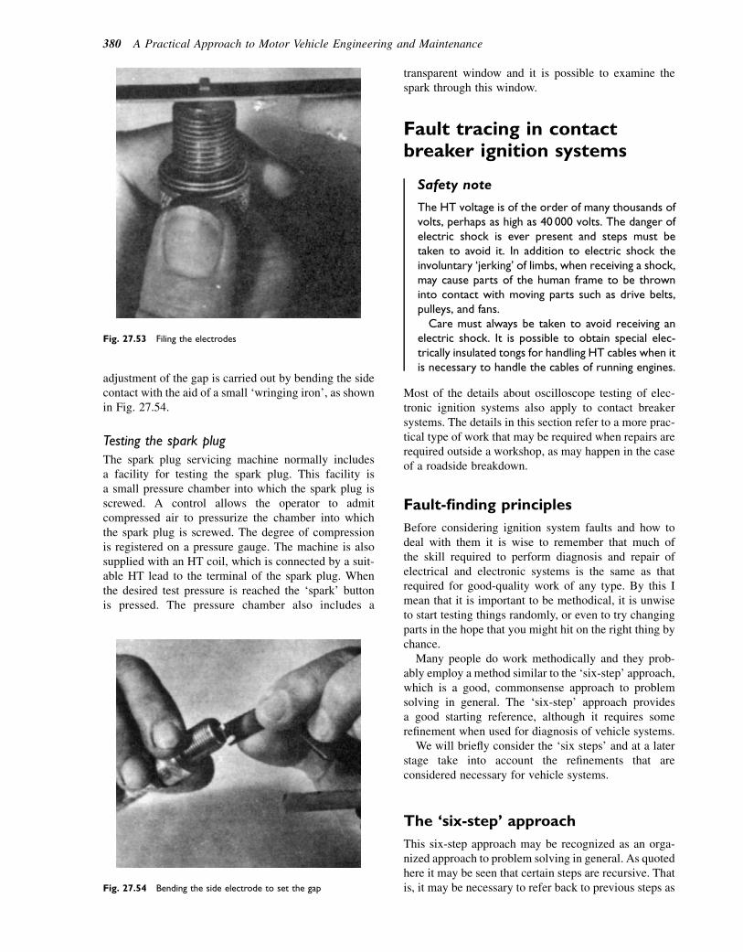
adjustment of the gap is carried out by bending the sidecontact with the aid of a small ‘wringing iron’, as shownin Fig. 27.54.
Testing the spark plug
The spark plug servicing machine normally includesa facility for testing the spark plug. This facility isa small pressure chamber into which the spark plug isscrewed. A control allows the operator to admitcompressed air to pressurize the chamber into whichthe spark plug is screwed. The degree of compressionis registered on a pressure gauge. The machine is alsosupplied with an HT coil, which is connected by a suit-able HT lead to the terminal of the spark plug. Whenthe desired test pressure is reached the ‘spark’ buttonis pressed. The pressure chamber also includes a
transparent window and it is possible to examine thespark through this window.
Fault tracing in contactbreaker ignition systems
Safety note
The HT voltage is of the order of many thousands ofvolts, perhaps as high as 40 000 volts. The danger ofelectric shock is ever present and steps must betaken to avoid it. In addition to electric shock theinvoluntary ‘jerking’ of limbs, when receiving a shock,may cause parts of the human frame to be throwninto contact with moving parts such as drive belts,pulleys, and fans.Care must always be taken to avoid receiving an
electric shock. It is possible to obtain special elec-trically insulated tongs for handling HT cables when itis necessary to handle the cables of running engines.
Most of the details about oscilloscope testing of elec-tronic ignition systems also apply to contact breakersystems. The details in this section refer to a more prac-tical type of work that may be required when repairs arerequired outside a workshop, as may happen in the caseof a roadside breakdown.
Fault-finding principles
Before considering ignition system faults and how todeal with them it is wise to remember that much ofthe skill required to perform diagnosis and repair ofelectrical and electronic systems is the same as thatrequired for good-quality work of any type. By this Imean that it is important to be methodical, it is unwiseto start testing things randomly, or even to try changingparts in the hope that you might hit on the right thing bychance.
Many people do work methodically and they prob-ably employ a method similar to the ‘six-step’ approach,which is a good, commonsense approach to problemsolving in general. The ‘six-step’ approach providesa good starting reference, although it requires somerefinement when used for diagnosis of vehicle systems.
We will briefly consider the ‘six steps’ and at a laterstage take into account the refinements that areconsidered necessary for vehicle systems.
The ‘six-step’ approach
This six-step approach may be recognized as an orga-nized approach to problem solving in general. As quotedhere it may be seen that certain steps are recursive. Thatis, it may be necessary to refer back to previous steps as
Fig. 27.53 Filing the electrodes
Fig. 27.54 Bending the side electrode to set the gap
380 A Practical Approach to Motor Vehicle Engineering and Maintenance
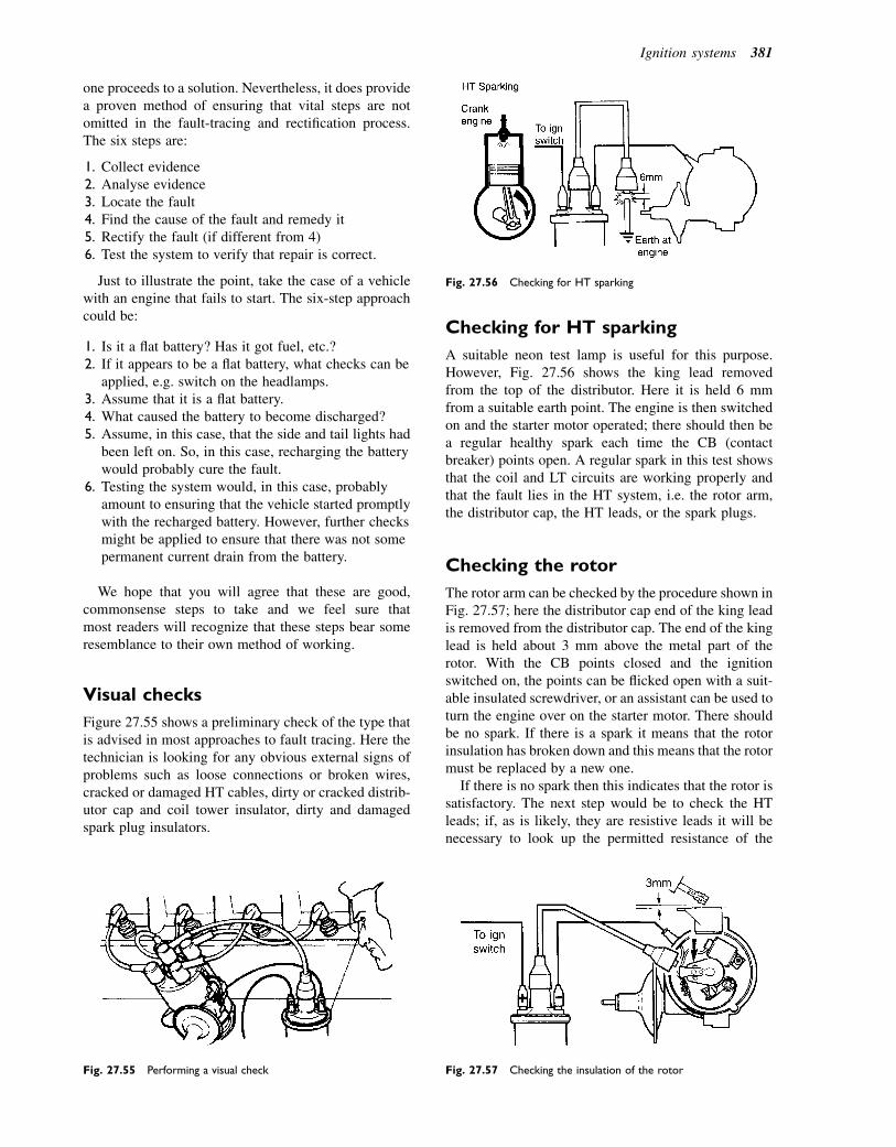
one proceeds to a solution. Nevertheless, it does providea proven method of ensuring that vital steps are notomitted in the fault-tracing and rectification process.The six steps are:
1. Collect evidence2. Analyse evidence3. Locate the fault4. Find the cause of the fault and remedy it5. Rectify the fault (if different from 4)6. Test the system to verify that repair is correct.
Just to illustrate the point, take the case of a vehiclewith an engine that fails to start. The six-step approachcould be:
1. Is it a flat battery? Has it got fuel, etc.?2. If it appears to be a flat battery, what checks can be
applied, e.g. switch on the headlamps.3. Assume that it is a flat battery.4. What caused the battery to become discharged?5. Assume, in this case, that the side and tail lights had
been left on. So, in this case, recharging the batterywould probably cure the fault.
6. Testing the system would, in this case, probablyamount to ensuring that the vehicle started promptlywith the recharged battery. However, further checksmight be applied to ensure that there was not somepermanent current drain from the battery.
We hope that you will agree that these are good,commonsense steps to take and we feel sure thatmost readers will recognize that these steps bear someresemblance to their own method of working.
Visual checks
Figure 27.55 shows a preliminary check of the type thatis advised in most approaches to fault tracing. Here thetechnician is looking for any obvious external signs ofproblems such as loose connections or broken wires,cracked or damaged HT cables, dirty or cracked distrib-utor cap and coil tower insulator, dirty and damagedspark plug insulators.
Checking for HT sparking
A suitable neon test lamp is useful for this purpose.However, Fig. 27.56 shows the king lead removedfrom the top of the distributor. Here it is held 6 mmfrom a suitable earth point. The engine is then switchedon and the starter motor operated; there should then bea regular healthy spark each time the CB (contactbreaker) points open. A regular spark in this test showsthat the coil and LT circuits are working properly andthat the fault lies in the HT system, i.e. the rotor arm,the distributor cap, the HT leads, or the spark plugs.
Checking the rotor
The rotor arm can be checked by the procedure shown inFig. 27.57; here the distributor cap end of the king leadis removed from the distributor cap. The end of the kinglead is held about 3 mm above the metal part of therotor. With the CB points closed and the ignitionswitched on, the points can be flicked open with a suit-able insulated screwdriver, or an assistant can be used toturn the engine over on the starter motor. There shouldbe no spark. If there is a spark it means that the rotorinsulation has broken down and this means that the rotormust be replaced by a new one.
If there is no spark then this indicates that the rotor issatisfactory. The next step would be to check the HTleads; if, as is likely, they are resistive leads it will benecessary to look up the permitted resistance of the
Fig. 27.55 Performing a visual check
Fig. 27.56 Checking for HT sparking
Fig. 27.57 Checking the insulation of the rotor
Ignition systems 381
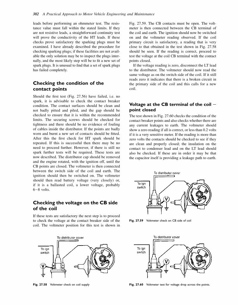
leads before performing an ohmmeter test. The resis-tance value must fall within the stated limits. If theyare not resistive leads, a straightforward continuity testwill prove the conductivity of the HT leads. If thesechecks prove satisfactory the sparking plugs must beexamined. I have already described the procedure forchecking sparking plugs; if these facilities are not avail-able the only solution may be to inspect the plugs inter-nally, and the most likely step will be to fit a new set ofspark plugs. It is unusual to find that a set of spark plugshas failed completely.
Checking the condition of thecontact points
Should the first test (Fig. 27.56) have failed, i.e. nospark, it is advisable to check the contact breakercondition. The contact surfaces should be clean andnot badly pitted and piled, and the gap should bechecked to ensure that it is within the recommendedlimits. The securing screws should be checked fortightness and there should be no evidence of foulingof cables inside the distributor. If the points are badlyworn and burnt a new set of contacts should be fitted.After this the first check for HT spark should berepeated. If this is successful then there may be noneed to proceed further. However, if there is still nospark further tests will be required. These tests arenow described. The distributor cap should be removedand the engine rotated, with the ignition off, until theCB points are closed. The voltmeter is then connectedbetween the switch side of the coil and earth. Theignition should then be switched on. The voltmetershould then read battery voltage (very closely) or,if it is a ballasted coil, a lower voltage, probably6e8 volts.
Checking the voltage on the CB sideof the coil
If these tests are satisfactory the next step is to proceedto check the voltage at the contact breaker side of thecoil. The voltmeter position for this test is shown in
Fig. 27.59. The CB contacts must be open. The volt-meter is then connected between the CB terminal ofthe coil and earth. The ignition should now be switchedon and the voltmeter reading observed. If the coilprimary circuit is satisfactory, a reading that is veryclose to that obtained in the test shown in Fig. 27.58should be seen. If the reading is correct, proceed totest the voltage at the coil CB terminal with the contactpoints closed.
If the voltage reading is zero, disconnect the LT leadto the distributor. The voltmeter should now read thesame voltage as on the switch side of the coil. If it stillreads zero it indicates that there is a broken circuit inthe primary side of the coil and this calls for a newcoil.
Voltage at the CB terminal of the coil epoint closed
The test shown in Fig. 27.60 checks the condition of thecontact breaker points and also checks whether there areany current leakages to earth. The voltmeter shouldshow a zero reading if all is correct, or less than 0.2 voltsif it is a very sensitive meter. If the reading is more thanzero volts the contacts should be checked to see if theyare clean and properly closed; the insulation on thecontact to condenser lead and on the LT lead shouldalso be checked. If these are in order it may be thatthe capacitor itself is providing a leakage path to earth.
Fig. 27.58 Voltmeter check on coil supply
Fig. 27.59 Voltmeter check on CB side of coil
Fig. 27.60 Voltmeter test for voltage drop across the points.
382 A Practical Approach to Motor Vehicle Engineering and Maintenance

Testing the capacitor
Now that the HT lead has been tested, and if there isstill no spark from this test, then the capacitor shouldbe tested. Figure 27.61 shows how a test capacitorcan be connected temporarily to perform this test.The original capacitor is unscrewed and lifted awayso that its casing does not make contact with earth.
A test capacitor with suitable crocodile clips and leadsis then connected as shown. The ignition is switchedon again and the engine turned over, on the startermotor. If a spark is obtained this is fairly convincingevidence that the capacitor should be renewed. If thereis still no spark, after testing the capacitor, the coilshould be replaced.
Checking the electrical condition ofthe ignition coil
The ignition coil can be checked as shown in Fig. 27.62.The secondary winding resistance should be high, prob-ably 10 kV. (Note: In some ignition coils the secondarywinding is earthed. In such cases the check forsecondary winding resistance would be made betweenthe HT connection and the coil earth.) The primarywinding resistance should be very low (the meter needsto be set to a very low ohm scale), 0.5e1 V.The tests shown here are of a general nature, i.e. they
do not apply to a specific system and, as with most otherwork on vehicle systems, it is important to have theFig. 27.61 Connecting a test capacitor
Fig. 27.62 Checking the HT coil
Ignition systems 383

figures that relate to the specific system being workedon. However, the tests do show the practical nature oftests that can be applied with the aid of a good-qualitymultimeter, sound knowledge of circuits, and therelevant information.
High-tension (HT) leads
The HT leads are the means by which the high-voltageelectrical energy that makes the spark is conducted tothe sparking plug. The high voltage, perhaps as high as40 kV, will wish to seek the shortest path to earth. Inorder to prevent HT leakage from the cables theymust be heavily insulated electrically. The insulatingmaterial must also be resistant to heat, and to oil,water, and any corrosive agents that they mayencounter; PVC is often used for the insulationbecause it possesses most of these properties. Toreduce radio interference, the conducting parts of HTleads are made to have electrical resistance. This resis-tance can change in use and HT leads should bechecked to ensure that the leads have the correct resis-tance. The resistance of HT leads varies considerably,a rough guide being 18 000 V per metre length. Thismeans that an HT cable of 300 mm length would havea resistance of 5400 V. It is a value that can bechecked by means of an ohmmeter and the resistancevalues and tolerances will be given in the workshopmanual.
As with any electric current in a conductor, the HTleads set up a magnetic field. In order to prevent oneHT cable inducing current in a neighbouring one, bymutual induction, cable routing as arranged by thevehicle manufacturer should always be adhered to.
Some practical applications,i.e. doing the job
A substantial amount of background theory has beencovered and we have shown how this theory is usedto make vehicle systems work. When systems breakdown or cease to function correctly it is the job ofthe vehicle service and repair technician to find outwhat is wrong and to put it right, and this is wherepractical skill, or competence, comes in to play. Ina book of this type it is not possible to cover everytype of vehicle system and we will not attempt to dothat. As with all work, proper safe working practicesmust be observed. Personal safety and the safety ofothers nearby must be protected, and the vehicle itselfmust be protected against damage by ensuring that thecorrect procedures prescribed by the manufacturer arefollowed and that wing and upholstery covers etc. areused.
Because of the global (international) nature of thevehicle industry, vehicle technicians will encountera range of products and it is unwise to attempt evensimple work without having good knowledge of theproduct, or access to the information and data relatingto the vehicle and system to be worked on.
The practical work described in this section gener-ally relates to a specific product and that is madeclear in the text. However, the devices chosen andthe work described have been selected because theyhighlight types of practical procedures and tests thatcan be applied across a range of vehicles. It isintended that this book should be used in conjunctionwith courses of practical instruction and learning onthe job.
The main source of information and guidanceabout repair and maintenance procedures is the manu-facturers workshop manual, which is often availableon CD-ROM.
Ignition timing
Because ignition timing varies with engine speed, it isnecessary to check both the static timing and thedynamic timing.
Static timing
The following list shows the ignition timing details fora four-cylinder in-line engine:
� Firing order 1e3e4e2. Static advance 108.� Contact breaker gap 0.40 mm.� Dwell angle 558.
For static advance setting, the figures of interest are:static advance angle of 108, contact breaker gap of0.40 mm, and the firing order.
When resetting the static timing after performingwork on the engine, such as on removing and refit-ting the distributor, it is necessary to ensure thatthe piston in the cylinder used for timing (usuallynumber 1) is on the compression stroke. The firingorder helps here because in this case the valves onnumber 4 cylinder will be ‘rocking’ when number 1piston is at top dead centre (TDC) on the compres-sion stroke. The 108 static advance tells us that thecontact breaker points must start to open at 108
before TDC. Engines normally carry timing markson the crankshaft pulley and these are made to alignwith a pointer on the engine block, or timing case, asshown in Fig. 27.63.
To position the piston at 108 before TDC the crankshould be rotated, by a spanner on the crankshaft pulleynut, in the direction of rotation of the engine. Thisensures that any ‘free play’ in the timing gears is takenup. To make the task more manageable it is probablywise to remove the sparking plugs. If the alignment is
384 A Practical Approach to Motor Vehicle Engineering and Maintenance
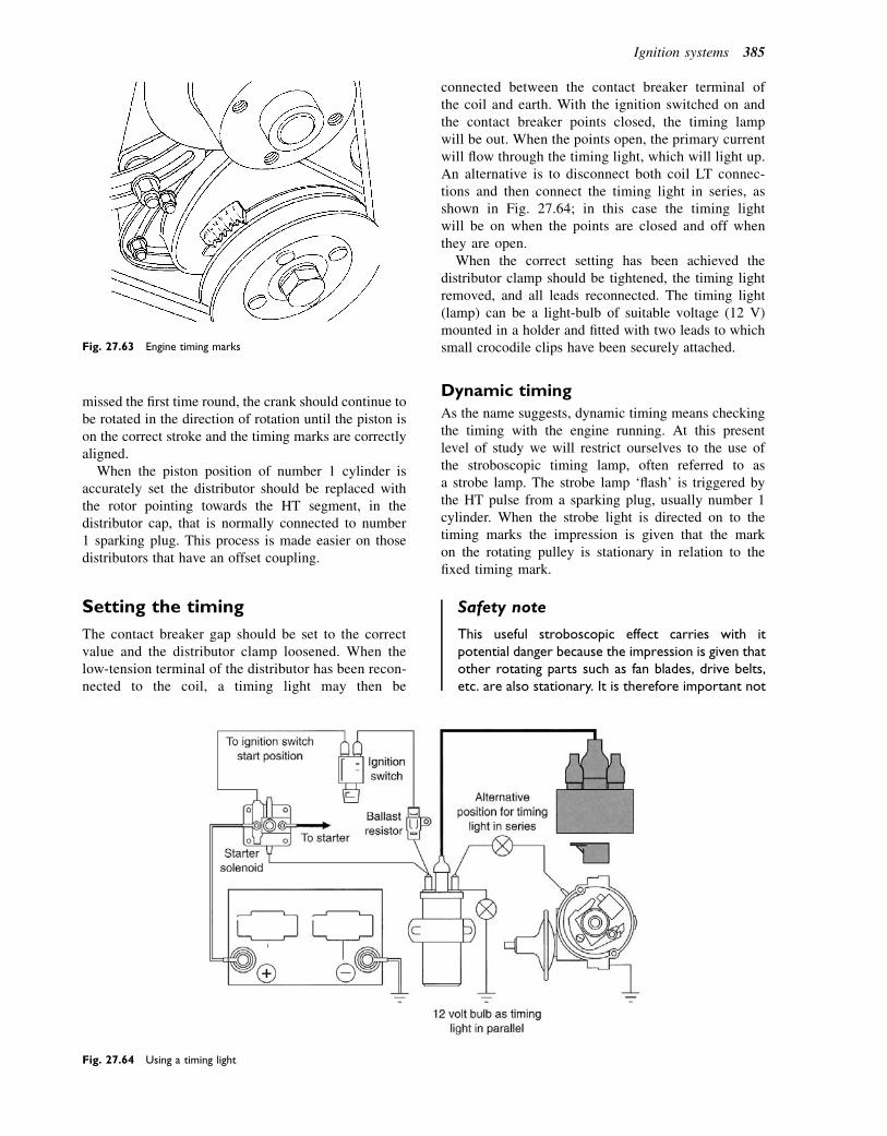
missed the first time round, the crank should continue tobe rotated in the direction of rotation until the piston ison the correct stroke and the timing marks are correctlyaligned.
When the piston position of number 1 cylinder isaccurately set the distributor should be replaced withthe rotor pointing towards the HT segment, in thedistributor cap, that is normally connected to number1 sparking plug. This process is made easier on thosedistributors that have an offset coupling.
Setting the timing
The contact breaker gap should be set to the correctvalue and the distributor clamp loosened. When thelow-tension terminal of the distributor has been recon-nected to the coil, a timing light may then be
connected between the contact breaker terminal ofthe coil and earth. With the ignition switched on andthe contact breaker points closed, the timing lampwill be out. When the points open, the primary currentwill flow through the timing light, which will light up.An alternative is to disconnect both coil LT connec-tions and then connect the timing light in series, asshown in Fig. 27.64; in this case the timing lightwill be on when the points are closed and off whenthey are open.
When the correct setting has been achieved thedistributor clamp should be tightened, the timing lightremoved, and all leads reconnected. The timing light(lamp) can be a light-bulb of suitable voltage (12 V)mounted in a holder and fitted with two leads to whichsmall crocodile clips have been securely attached.
Dynamic timing
As the name suggests, dynamic timing means checkingthe timing with the engine running. At this presentlevel of study we will restrict ourselves to the use ofthe stroboscopic timing lamp, often referred to asa strobe lamp. The strobe lamp ‘flash’ is triggered bythe HT pulse from a sparking plug, usually number 1cylinder. When the strobe light is directed on to thetiming marks the impression is given that the markon the rotating pulley is stationary in relation to thefixed timing mark.
Safety note
This useful stroboscopic effect carries with itpotential danger because the impression is given thatother rotating parts such as fan blades, drive belts,etc. are also stationary. It is therefore important not
Fig. 27.63 Engine timing marks
Fig. 27.64 Using a timing light
Ignition systems 385
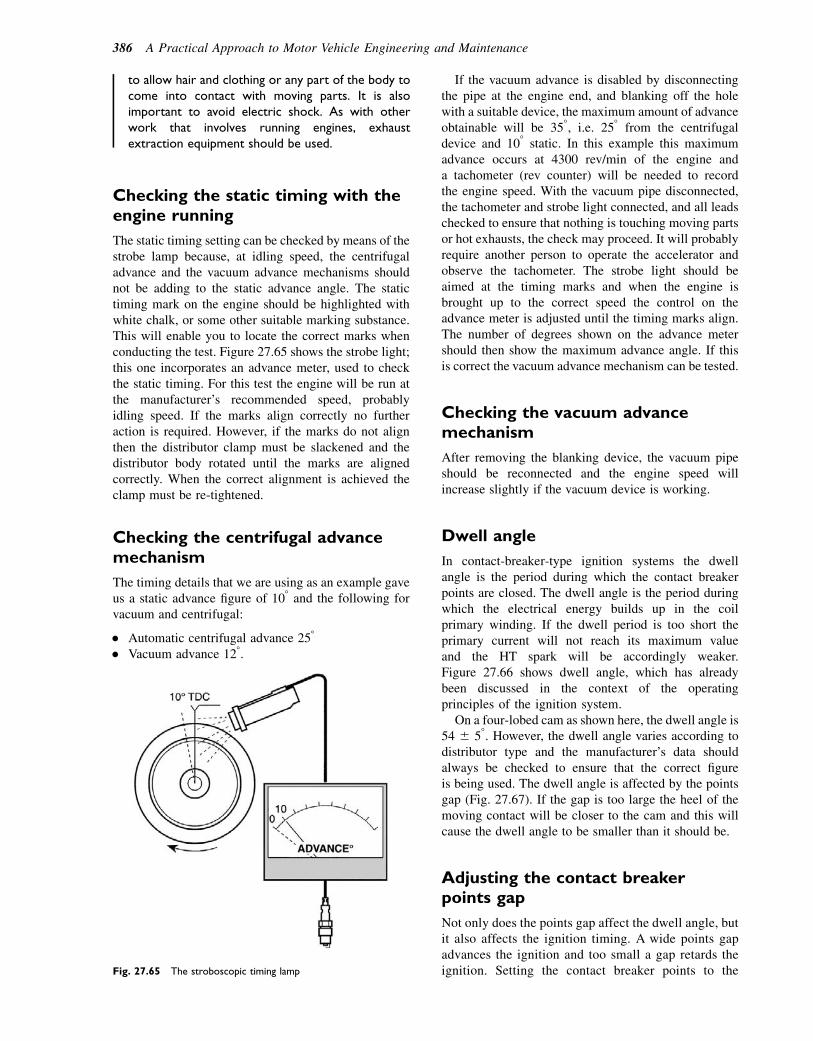
to allow hair and clothing or any part of the body tocome into contact with moving parts. It is alsoimportant to avoid electric shock. As with otherwork that involves running engines, exhaustextraction equipment should be used.
Checking the static timing with theengine running
The static timing setting can be checked by means of thestrobe lamp because, at idling speed, the centrifugaladvance and the vacuum advance mechanisms shouldnot be adding to the static advance angle. The statictiming mark on the engine should be highlighted withwhite chalk, or some other suitable marking substance.This will enable you to locate the correct marks whenconducting the test. Figure 27.65 shows the strobe light;this one incorporates an advance meter, used to checkthe static timing. For this test the engine will be run atthe manufacturer’s recommended speed, probablyidling speed. If the marks align correctly no furtheraction is required. However, if the marks do not alignthen the distributor clamp must be slackened and thedistributor body rotated until the marks are alignedcorrectly. When the correct alignment is achieved theclamp must be re-tightened.
Checking the centrifugal advancemechanism
The timing details that we are using as an example gaveus a static advance figure of 108 and the following forvacuum and centrifugal:
� Automatic centrifugal advance 258
� Vacuum advance 128.
If the vacuum advance is disabled by disconnectingthe pipe at the engine end, and blanking off the holewith a suitable device, the maximum amount of advanceobtainable will be 358, i.e. 258 from the centrifugaldevice and 108 static. In this example this maximumadvance occurs at 4300 rev/min of the engine anda tachometer (rev counter) will be needed to recordthe engine speed. With the vacuum pipe disconnected,the tachometer and strobe light connected, and all leadschecked to ensure that nothing is touching moving partsor hot exhausts, the check may proceed. It will probablyrequire another person to operate the accelerator andobserve the tachometer. The strobe light should beaimed at the timing marks and when the engine isbrought up to the correct speed the control on theadvance meter is adjusted until the timing marks align.The number of degrees shown on the advance metershould then show the maximum advance angle. If thisis correct the vacuum advance mechanism can be tested.
Checking the vacuum advancemechanism
After removing the blanking device, the vacuum pipeshould be reconnected and the engine speed willincrease slightly if the vacuum device is working.
Dwell angle
In contact-breaker-type ignition systems the dwellangle is the period during which the contact breakerpoints are closed. The dwell angle is the period duringwhich the electrical energy builds up in the coilprimary winding. If the dwell period is too short theprimary current will not reach its maximum valueand the HT spark will be accordingly weaker.Figure 27.66 shows dwell angle, which has alreadybeen discussed in the context of the operatingprinciples of the ignition system.
On a four-lobed cam as shown here, the dwell angle is54 6 58. However, the dwell angle varies according todistributor type and the manufacturer’s data shouldalways be checked to ensure that the correct figureis being used. The dwell angle is affected by the pointsgap (Fig. 27.67). If the gap is too large the heel of themoving contact will be closer to the cam and this willcause the dwell angle to be smaller than it should be.
Adjusting the contact breakerpoints gap
Not only does the points gap affect the dwell angle, butit also affects the ignition timing. A wide points gapadvances the ignition and too small a gap retards theignition. Setting the contact breaker points to theFig. 27.65 The stroboscopic timing lamp
386 A Practical Approach to Motor Vehicle Engineering and Maintenance
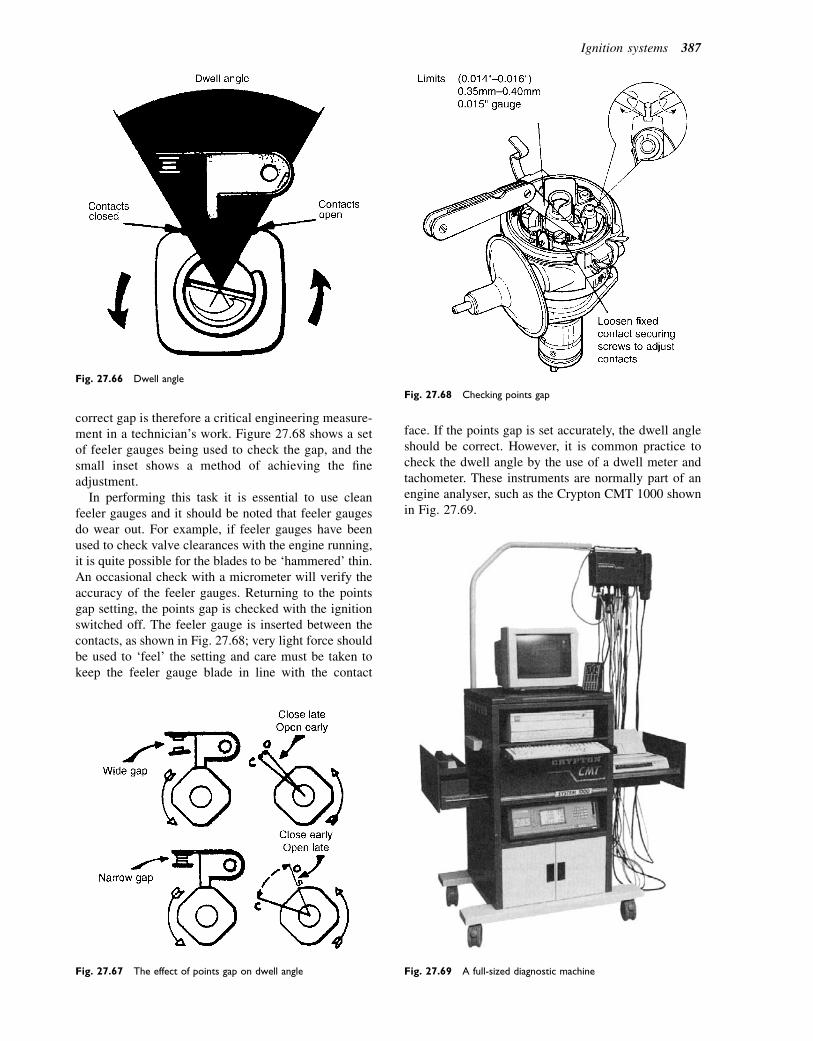
correct gap is therefore a critical engineering measure-ment in a technician’s work. Figure 27.68 shows a setof feeler gauges being used to check the gap, and thesmall inset shows a method of achieving the fineadjustment.
In performing this task it is essential to use cleanfeeler gauges and it should be noted that feeler gaugesdo wear out. For example, if feeler gauges have beenused to check valve clearances with the engine running,it is quite possible for the blades to be ‘hammered’ thin.An occasional check with a micrometer will verify theaccuracy of the feeler gauges. Returning to the pointsgap setting, the points gap is checked with the ignitionswitched off. The feeler gauge is inserted between thecontacts, as shown in Fig. 27.68; very light force shouldbe used to ‘feel’ the setting and care must be taken tokeep the feeler gauge blade in line with the contact
face. If the points gap is set accurately, the dwell angleshould be correct. However, it is common practice tocheck the dwell angle by the use of a dwell meter andtachometer. These instruments are normally part of anengine analyser, such as the Crypton CMT 1000 shownin Fig. 27.69.
Fig. 27.66 Dwell angle
Fig. 27.67 The effect of points gap on dwell angle
Fig. 27.68 Checking points gap
Fig. 27.69 A full-sized diagnostic machine
Ignition systems 387
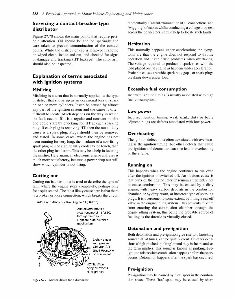
Servicing a contact-breaker-typedistributor
Figure 27.70 shows the main points that require peri-odic attention. Oil should be applied sparingly andcare taken to prevent contamination of the contactpoints. While the distributor cap is removed it shouldbe wiped clean, inside and out, and checked for signsof damage and tracking (HT leakage). The rotor armshould also be inspected.
Explanation of terms associatedwith ignition systems
Misfiring
Misfiring is a term that is normally applied to the typeof defect that shows up as an occasional loss of sparkon one or more cylinders. It can be caused by almostany part of the ignition system and the cause is oftendifficult to locate. Much depends on the way in whichthe fault occurs. If it is a regular and constant misfireone could start by checking for HT at each sparkingplug. If each plug is receiving HT, then the most likelycause is a spark plug. Plugs should then be removedand tested. In some cases, where the engine has notbeen running for very long, the insulator of a non-firingspark plug will be significantly cooler to the touch, thanthe other plug insulators. This may be a help in locatingthe misfire. Here again, an electronic engine analyser ismuch more satisfactory, because a power drop test willshow which cylinder is not firing.
Cutting out
Cutting out is a term that is used to describe the type offault where the engine stops completely, perhaps onlyfor a split second. The most likely cause here is that thereis a broken or loose connection, which breaks the circuit
momentarily. Careful examination of all connections, and‘wiggling’ of cables whilst conducting a voltage drop testacross the connectors, should help to locate such faults.
Hesitation
This normally happens under acceleration; the symp-toms are that the engine does not respond to throttleoperation and it can cause problems when overtaking.The voltage required to produce a spark rises with theload placed on the engine as happens under acceleration.Probable causes are wide spark plug gaps, or spark plugsbreaking down under load.
Excessive fuel consumption
Incorrect ignition timing is usually associated with highfuel consumption.
Low power
Incorrect ignition timing, weak spark, dirty or badlyadjusted plugs are defects associated with low power.
Overheating
The ignition defect most often associated with overheat-ing is the ignition timing, but other defects that causepre-ignition and detonation can also lead to overheatingof the engine.
Running on
This happens when the engine continues to run evenafter the ignition is switched off. An obvious cause isthat parts of the engine interior remain sufficiently hotto cause combustion. This may be caused by a dirtyengine, with heavy carbon deposits in the combustionchamber, or by dirty, worn, or incorrect type of sparkingplugs. It is overcome, to some extent, by fitting a cut-offvalve in the engine idling system. This prevents mixturefrom entering the combustion chamber through theengine idling system, this being the probable source offuelling as the throttle is virtually closed.
Detonation and pre-ignition
Both detonation and pre-ignition give rise to a knockingsound that, at times, can be quite violent. On other occa-sions a high-pitched ‘pinking’soundmay be heard and, asthe term implies, this sound is known as pinking. Pre-ignition ariseswhen combustion happens before the sparkoccurs. Detonation happens after the spark has occurred.
Pre-ignition
Pre-ignition may be caused by ‘hot’ spots in the combus-tion space. These ‘hot’ spots may be caused by sharpFig. 27.70 Service details for a distributor
388 A Practical Approach to Motor Vehicle Engineering and Maintenance
edges and rough metallic surfaces, glowing deposits(carbon), overheated spark plugs, and badly seated valves.As a result of ignition starting before the spark occurs, thepressure and temperature in the cylinder rise to high levelsat the wrong time. This gives rise to poor performance,engine knock, and eventual engine damage. Some of theprobable causes of pre-ignition are listed below:
� Sharp edges and rough metallic surfaces. These arelikely to be caused by manufacturing defects and arenormally rectified at that stage. However, if an enginehas been opened up for repair work it is possible thatcareless use of tools may damage a surface. Shouldthis be the case, the remedy would be to remove theroughness by means of a scraper, a file, or a burr.
� Glowing deposits (carbon). This is most likely tooccur in an engine that has covered a high mileage.Decarbonizing the engine (a decoke) would probablybe the answer here.
� Overheated spark plugs. In this case there arevarious factors to consider: Are the spark plugs of thecorrect type and heat range? Are the spark plugsclean? Are the electrodes worn thin?
� Badly seated valves. If a poppet-type valve does notseat properly it is possible for part of the valve headto form a hot spot. Failure to seat squarely could becaused by a bent valve, a misaligned valve guide and,in the case of older engines, a badly reconditionedvalve. In each case the remedy would be to rectify thefault indicated.
In addition to the above defects, combustion knockcan arise from use of the incorrect fuel. The octanerating of a fuel is the critical factor here. Tetra-ethyllead (leaded fuel) used to be the method of alteringthe octane rating (anti-knock value) of petroleum spirit.Now that most spark ignition engines are fitted withcatalytic converters for emissions control, leaded fuelscannot be used. There are different octane grades ofunleaded fuel and many electronically controlledengines are provided with a simple means of alteringsettings if a driver wishes to use a different octane ratingfuel from the one that she/he has been using.
I hope that you will agree that these are good,commonsense steps to take and feel sure thatmost readers will recognize that these steps bear someresemblance to their own method of working.
In the following cases it is assumed that the abovesteps have been followed and that the fault has beenfound to exist in the area of the ignition system.
Poor starting or failure to start
For current purposes we will assume that the fuel andelectrical systems are in good order. In particular, thatthe battery is fully charged and that the starter motoris capable of rotating the engine correctly. We shall
also assume that the mechanical condition of the engineis good and that the fault has been identified as being inthe area of the ignition system.
Poor starting
If the controls are operated correctly, the engine shouldstart promptly. The time taken to start up may vary withair temperature. For example, when it is very cold thecranking speed of the engine will be affected by theviscosity of the lubricating oil, and the mixture enteringthe engine is affected by contact with cold surfaces.Generally, an engine will start more promptly when ithas warmed up than it will when it is cold.
For ‘poor’ starting we are therefore looking at caseswhere, taking account of the above factors, the engineeither takes a long time to start or is reluctant to startat all.
The ignition system faults that have a bearing on theproblem of poor starting are:
� Weak spark. This could be caused by loss ofelectrical energy in the ignition circuit, or failure togenerate sufficient energy for a spark, in the firstinstance. Loss of electrical energy could be due todefective connection and/or defective insulation ineither the low-tension or the high-tension circuit. Arange of tests and checks that can be carried out isdescribed in the section on servicing and repair.
� Spark occurring sometimes but not at other times.This is known as an intermittent fault. Here again, theproblem could lie in either or both the LT and the HTcircuits.
� Spark occurring at the wrong time. In most casesthis means that the ignition timing is incorrectly set.
Failure to start
As it is ignition faults that we are considering, theobvious place to start is the sparking plug gap. Failureto start is probably due to there being no spark, or a sparkthat is too weak to cause combustion. However, if theignition timing is not correct, or the HT leads havebeen wrongly connected (not in accordance with thefiring order), the engine may also fail to start.
Learning tasks (ignition)
Do not attempt any practical work until you have beenproperly trained. You must always seek the permissionand advice of your supervisor before you attempt any ofthe practical tasks.Much of the NVQ assessment is based on work thatyou have actually performed. Each time youcomplete the tasks you should keep a record andnote down the tools and equipment that you haveused.
Ignition systems 389

1. Make a list of the precautions to be taken whenworking on ignition systems.
2. Describe the procedure for setting the static igni-tion timing on an engine that has a contact-breaker-type ignition system.
3. Give details of the procedure and type of feelergauges used to set the pick-up to rotor air gapin an electronic, contact-breakerless, ignitionsystem.
4. Take a set of ignition HT leads and measure thelength in centimetres and the resistance in kVof each lead. Compare the figures with thosegiven in this book, or in the workshop manualfor the vehicle. Write down the result and statewhether or not the leads are in good condition.
5. Examine a set of sparking plugs from an engine.Measure and record:(a) the spark gaps(b) the reach of each plug(c) the thread diameter(d) the recommended tightening torque(e) note the type of spark plug (not the make)
and state whether they are intended for usein a hot running engine or a cold runningengine.
6. Examine a distributorless ignition system. Writedown the number of ignition coils and theposition of the sensor that triggers the ignitionpulses.
7. Describe, with the aid of diagrams, a simple prac-tical test that can be used to check the electricalcondition of a rotor arm.
8. Perform a test to check the electrical output ofa magnetic-pulse-type generator that is used inan electronic ignition system.
9. Obtain an ignition coil and measure the resistanceof the primary winding and the secondarywinding. Record the figures and compare themwith the figures given in this book, then writedown your opinion about the condition of thecoil. State whether or not the coil is for use ina ballasted ignition system.
10. Describe the procedure for setting up a garage-type oscilloscope to check ignition coil polarity.
Self-assessment questions1. A Hall effect ignition system sensor:
(a) requires a supply of electricity(b) generates electricity by electromagnetism(c) can only be used on ignition systems that have
a distributor(d) can only be used on four-cylinder engines.
2. In a test on a contact-breaker-type ignition systemwith the points closed and the ignition switched on,the voltage drop across the points should be:(a) 14 volts(b) not more than 0.2 volts(c) 2.5 volts(d) 2 volts.
3. In a ‘lost spark’ ignition system each cylinder hasa spark:(a) on the induction stroke as well as at the end of
the compression stroke(b) on the exhaust stroke as well as at the end of
the power stroke(c) twice on the power stroke(d) on the exhaust stroke as well as at the end of
the compression stroke.4. Ignition-related faults that affect the emissions
controls on the vehicle:(a) cause the MIL lamp to illuminate on EOBD
systems(b) cause the vehicle to be disabled(c) require the vehicle to be taken off the road
immediately(d) should be left to rectify themselves.
5. A set of ignition HT leads are required to havea resistance of 18 kV per metre of length. One ofthese leads that is 430 mm long will havea resistance of:(a) 41.86 V(b) 7740 V(c) 4186 V(d) 0.7 kV.
6. Sparking plugs that ‘run’ hot have a long heat path,and sparking plugs that ‘run’ cold have a short heatpath. The sparking plugs fitted to an engine thatruns ‘cool’ would have:(a) a short heat path(b) tapered seats(c) a long heat path(d) short reach.
7. The ‘firing line’ on an oscilloscope trace of ignitionHT voltage represents:(a) the high voltage that is needed to cause the
spark to bridge the sparking plug gap(b) the current in the primary winding of the ignition
coil(c) the condition of the condenser(d) the airefuel ratio of the mixture in the
cylinder.8. A knock sensor is used:
(a) to allow the ECM to alter the ignition timing(b) to alert the driver to mechanical noise from
wide valve clearances(c) to allow catalytic converters to operate on
leaded fuel(d) on contact-breaker-type ignition systems
only.
390 A Practical Approach to Motor Vehicle Engineering and Maintenance
9. Pre-ignition happens:(a) when the static ignition timing is too far
advanced(b) when combustion occurs before the spark(c) when pressure waves cause a region of high
pressure, in the combustion chamber, after thespark has occurred
(d) when the ignition is retarded.10. In engine management the ignition timing can be
altered to suit engine wear. When new parts arefitted to replace worn or damaged ones on thistype of ignition system, the vehicle:(a) should have a new ECM fitted(b) should be operated under normal running
conditions for a length of time that allows theECM to adjust to the new parts
(c) should be returned to the customer withoutadvising them that it may take time for thevehicle to return to its best workingcondition
(d) should have the entire ignition systemrenewed.
11. The vacuum-operated timing control ondistributor-type ignition systems:(a) changes the ignition timing to suit engine
speed(b) changes the ignition timing to suit engine
temperature(c) changes the ignition timing to suit load on the
engine(d) changes the airefuel ratio.
Ignition systems 391
28Electrical systems and circuits
Topics covered in thischapter
Central door locking e remoteScreen wipersScreen washersVehicle security alarmElectric window operationElectrically operated mirrorsVehicle lighting systemsSupplementary restraint systems e air bagsand seat-belt pre-tensionersInstrumentsCircuit protection e fuses and circuit breakers
Central door-locking systems
Manual operation
A central door-locking system permits all doors, oftenincluding the boot lid or tailgate, to be locked centrallyfrom the driver’s door and normally includes the frontpassenger’s door as well.
The locking and unlocking action is produced by anelectromechanical device, such as a solenoid or an elec-tric motor. The door key operates a switch that controlsthe electrical supply that actuates the door lock mecha-nism, and the remote control activates a switchingcircuit in the electronic control module (ECM) thatalso actuates the locking mechanism. For safety andconvenience, the interior door handles also operate theunlocking mechanism.
Remote operation
The remote control operates in much the same way asthe remote control for a domestic television. A uniquecode is transmitted from the remote control that is nor-mally contained in the ignition key. Two types of trans-mitter are used, infrared and radio frequency. Theelectronic control module (ECM) that controls thesupply of current to the door lock actuators contains
a sensor that detects infrared signals or, in the case ofradio frequency systems, an aerial to detect the radiofrequency signal. The remote signal is normally effec-tive over a range of several metres. Figure 28.1 showsthe general principle of central locking systems.
The remote controller
The encoded signals that are transmitted by the remotecontroller are producedby electronic circuits that are ener-gized by a small battery that is housed in the controller. Apad on the controller is pressed for unlocking and anotherpad is pressed for locking purposes. The device may alsobe provided with an LED that indicates battery level.
A simple central locking circuit
Both the manual central lock system and the remotecentral lock systems employ similar circuits and actuatorsinside the doors. A general description of central lockingsystem circuits, of the type shown in Fig. 28.2, shouldserve to bring about the necessary level of understanding.
Solenoid
The type of solenoid used in door-locking systemsis shown in Fig. 28.2(a). The flow of current in onedirection causes the doors to lock and when currentflows in the opposite direction the doors are unlocked.The reversal of current is performed by the ECM.
Motor
The motors (Fig. 28.2(b)) used for door-locking systemsare normally of the permanent magnet type because theyare capable of being reversed by changing the directionof current flow through the motor. The motorized opera-tion is considered to be slightly smoother in operationthan in the solenoid system. The reversal of current flowis achieved through the switching action provided by theECM.
Circuit protection
In addition to a fuse, door-locking circuits are oftenequipped with a thermal circuit breaker.
� 2011 Allan Bonnick and Derek Newbold. Published by Elsevier Ltd. All rights reserved
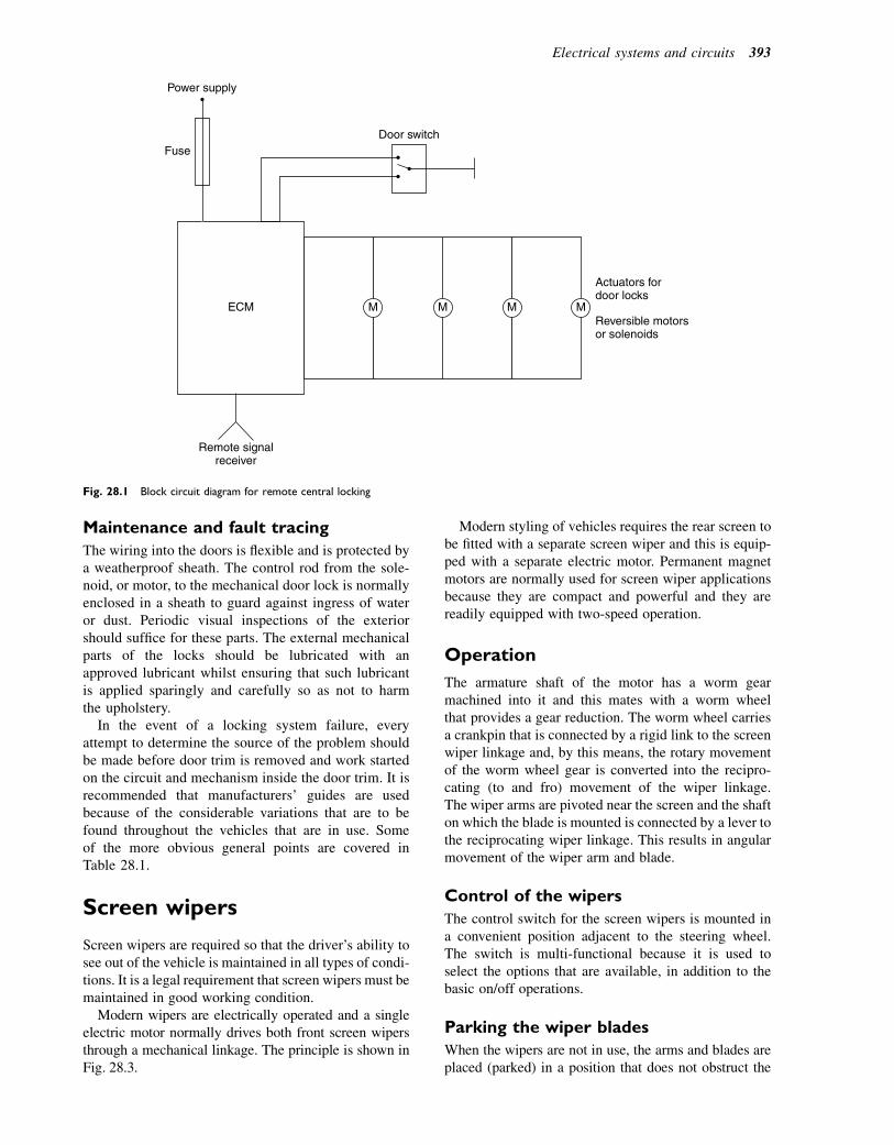
Maintenance and fault tracing
The wiring into the doors is flexible and is protected bya weatherproof sheath. The control rod from the sole-noid, or motor, to the mechanical door lock is normallyenclosed in a sheath to guard against ingress of wateror dust. Periodic visual inspections of the exteriorshould suffice for these parts. The external mechanicalparts of the locks should be lubricated with anapproved lubricant whilst ensuring that such lubricantis applied sparingly and carefully so as not to harmthe upholstery.
In the event of a locking system failure, everyattempt to determine the source of the problem shouldbe made before door trim is removed and work startedon the circuit and mechanism inside the door trim. It isrecommended that manufacturers’ guides are usedbecause of the considerable variations that are to befound throughout the vehicles that are in use. Someof the more obvious general points are covered inTable 28.1.
Screen wipers
Screen wipers are required so that the driver’s ability tosee out of the vehicle is maintained in all types of condi-tions. It is a legal requirement that screen wipers must bemaintained in good working condition.
Modern wipers are electrically operated and a singleelectric motor normally drives both front screen wipersthrough a mechanical linkage. The principle is shown inFig. 28.3.
Modern styling of vehicles requires the rear screen tobe fitted with a separate screen wiper and this is equip-ped with a separate electric motor. Permanent magnetmotors are normally used for screen wiper applicationsbecause they are compact and powerful and they arereadily equipped with two-speed operation.
Operation
The armature shaft of the motor has a worm gearmachined into it and this mates with a worm wheelthat provides a gear reduction. The worm wheel carriesa crankpin that is connected by a rigid link to the screenwiper linkage and, by this means, the rotary movementof the worm wheel gear is converted into the recipro-cating (to and fro) movement of the wiper linkage.The wiper arms are pivoted near the screen and the shafton which the blade is mounted is connected by a lever tothe reciprocating wiper linkage. This results in angularmovement of the wiper arm and blade.
Control of the wipers
The control switch for the screen wipers is mounted ina convenient position adjacent to the steering wheel.The switch is multi-functional because it is used toselect the options that are available, in addition to thebasic on/off operations.
Parking the wiper blades
When the wipers are not in use, the arms and blades areplaced (parked) in a position that does not obstruct the
M M M M
Remote signalreceiver
Power supply
FuseDoor switch
Actuators fordoor locks
Reversible motorsor solenoids
ECM
Fig. 28.1 Block circuit diagram for remote central locking
Electrical systems and circuits 393
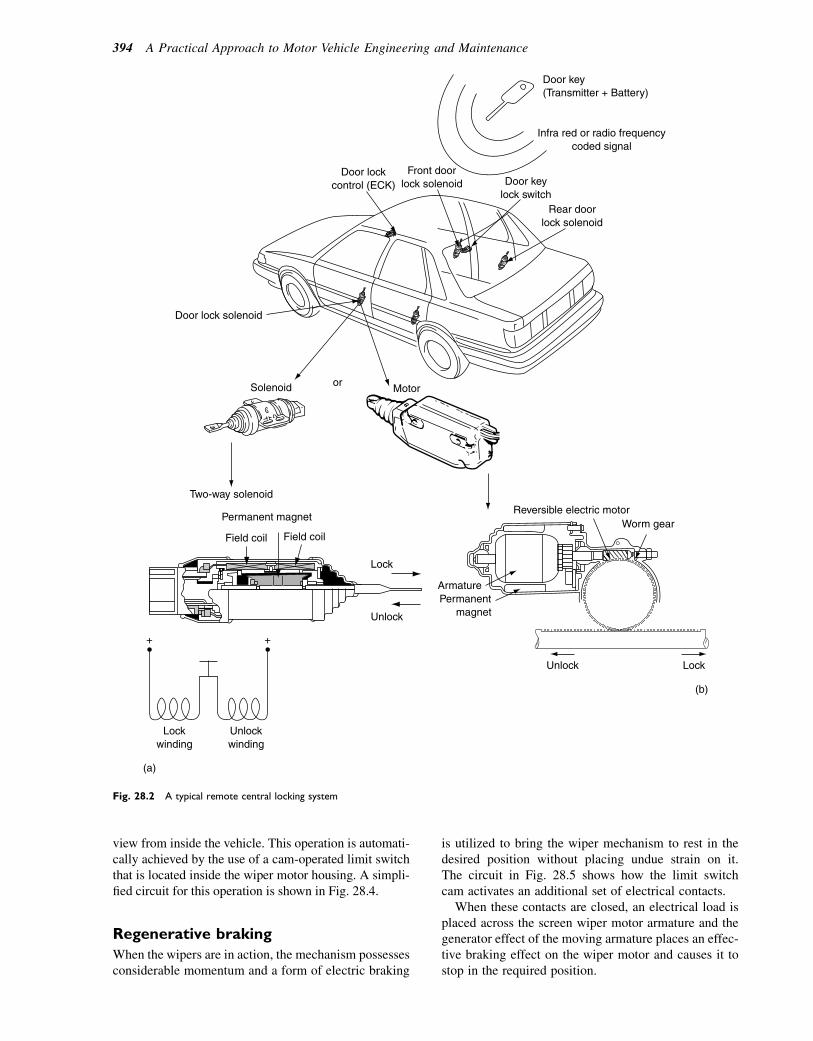
view from inside the vehicle. This operation is automati-cally achieved by the use of a cam-operated limit switchthat is located inside the wiper motor housing. A simpli-fied circuit for this operation is shown in Fig. 28.4.
Regenerative braking
When the wipers are in action, the mechanism possessesconsiderable momentum and a form of electric braking
is utilized to bring the wiper mechanism to rest in thedesired position without placing undue strain on it.The circuit in Fig. 28.5 shows how the limit switchcam activates an additional set of electrical contacts.
When these contacts are closed, an electrical load isplaced across the screen wiper motor armature and thegenerator effect of the moving armature places an effec-tive braking effect on the wiper motor and causes it tostop in the required position.
Door key (Transmitter + Battery)
Infra red or radio frequency coded signal
Door lock control (ECK)
Door lock solenoid
Front door lock solenoid Door key
lock switch Rear door
lock solenoid
Motor or Solenoid
Two-way solenoid
Permanent magnet
Field coil Field coil
Lock
Unlock
Reversible electric motor
Permanent magnet
Armature
Worm gear
Lock Unlock
(a)
(b)
+ +
Lock winding
Unlock winding
Fig. 28.2 A typical remote central locking system
394 A Practical Approach to Motor Vehicle Engineering and Maintenance
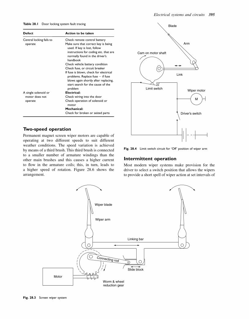
Two-speed operation
Permanent magnet screen wiper motors are capable ofoperating at two different speeds to suit differentweather conditions. The speed variation is achievedby means of a third brush. This third brush is connectedto a smaller number of armature windings than theother main brushes and this causes a higher currentto flow in the armature coils; this, in turn, leads toa higher speed of rotation. Figure 28.6 shows thearrangement.
Intermittent operation
Most modern wiper systems make provision for thedriver to select a switch position that allows the wipersto provide a short spell of wiper action at set intervals of
Table 28.1 Door locking system fault tracing
Defect Action to be taken
Central locking fails to
operate
Check remote control battery
Make sure that correct key is being
used. If key is lost, follow
instructions for coding etc. that are
normally found in the driver’s
handbook
Check vehicle battery condition
Check fuse, or circuit breaker
If fuse is blown, check for electrical
problems. Replace fuse e if fuse
blows again shortly after replacing,
start search for the cause of the
problem
A single solenoid or
motor does not
operate
Electrical:
Check wiring into the door
Check operation of solenoid or
motor
Mechanical:
Check for broken or seized parts
Motor
Worm & wheelreduction gear
Slide block
Linking bar
Wiper blade
Wiper arm
Connecting rod
Fig. 28.3 Screen wiper system
Link
Limit switchWiper motor
Driver’s switch
Arm
Cam on motor shaft
Blade
M
Fig. 28.4 Limit switch circuit for ‘Off’ position of wiper arm
Electrical systems and circuits 395
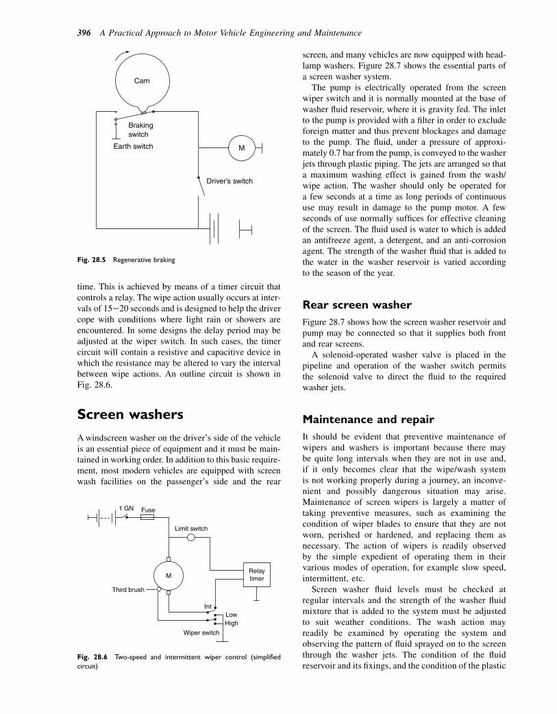
time. This is achieved by means of a timer circuit thatcontrols a relay. The wipe action usually occurs at inter-vals of 15e20 seconds and is designed to help the drivercope with conditions where light rain or showers areencountered. In some designs the delay period may beadjusted at the wiper switch. In such cases, the timercircuit will contain a resistive and capacitive device inwhich the resistance may be altered to vary the intervalbetween wipe actions. An outline circuit is shown inFig. 28.6.
Screen washers
Awindscreen washer on the driver’s side of the vehicleis an essential piece of equipment and it must be main-tained in working order. In addition to this basic require-ment, most modern vehicles are equipped with screenwash facilities on the passenger’s side and the rear
screen, and many vehicles are now equipped with head-lamp washers. Figure 28.7 shows the essential parts ofa screen washer system.
The pump is electrically operated from the screenwiper switch and it is normally mounted at the base ofwasher fluid reservoir, where it is gravity fed. The inletto the pump is provided with a filter in order to excludeforeign matter and thus prevent blockages and damageto the pump. The fluid, under a pressure of approxi-mately 0.7 bar from the pump, is conveyed to the washerjets through plastic piping. The jets are arranged so thata maximum washing effect is gained from the wash/wipe action. The washer should only be operated fora few seconds at a time as long periods of continuoususe may result in damage to the pump motor. A fewseconds of use normally suffices for effective cleaningof the screen. The fluid used is water to which is addedan antifreeze agent, a detergent, and an anti-corrosionagent. The strength of the washer fluid that is added tothe water in the washer reservoir is varied accordingto the season of the year.
Rear screen washer
Figure 28.7 shows how the screen washer reservoir andpump may be connected so that it supplies both frontand rear screens.
A solenoid-operated washer valve is placed in thepipeline and operation of the washer switch permitsthe solenoid valve to direct the fluid to the requiredwasher jets.
Maintenance and repair
It should be evident that preventive maintenance ofwipers and washers is important because there maybe quite long intervals when they are not in use and,if it only becomes clear that the wipe/wash systemis not working properly during a journey, an inconve-nient and possibly dangerous situation may arise.Maintenance of screen wipers is largely a matter oftaking preventive measures, such as examining thecondition of wiper blades to ensure that they are notworn, perished or hardened, and replacing them asnecessary. The action of wipers is readily observedby the simple expedient of operating them in theirvarious modes of operation, for example slow speed,intermittent, etc.
Screen washer fluid levels must be checked atregular intervals and the strength of the washer fluidmixture that is added to the system must be adjustedto suit weather conditions. The wash action mayreadily be examined by operating the system andobserving the pattern of fluid sprayed on to the screenthrough the washer jets. The condition of the fluidreservoir and its fixings, and the condition of the plastic
Brakingswitch
Driver’s switch
M
Cam
Earth switch
Fig. 28.5 Regenerative braking
1 GN Fuse
Limit switch
Third brush
Relaytimer
IntLowHigh
Wiper switch
M
Fig. 28.6 Two-speed and intermittent wiper control (simplified
circuit)
396 A Practical Approach to Motor Vehicle Engineering and Maintenance

tubes that connect the pump outlet to the jets, should bechecked to ensure that they are secure and in goodcondition.
Repairs and fault tracing
For current purposes, screen wiper defects may usefullybe grouped into two categories, namely (1) electricaland (2) mechanical.
Electrical defects
Problem e electrical overload
Possible effect e fuse blown or circuit breakertriggered
Some thermal circuit breakers operate by breaking thecircuit at intervals, in which case the sporadic behaviourof the wipers will indicate that there is somethingwrong. Persistent operation of the circuit breaker meansthat there is a problem that requires attention becausethe wiper circuit is being overloaded. In the case ofa blown fuse, it may be that the fuse has blown becauseof a temporary overload such as ice on the screen orexcessively dirty conditions. In this case it would prob-ably be in order to replace the fuse and perform a fulltest on the wipers, ensuring a clean and wet screenbefore attempting any test. Should the fuse blow again,or the circuit breaker come into operation again, thesystem must be examined to see whether it is anelectrical fault or a mechanical fault.
Electrical overload may arise from a short-circuitwhere some part of the wiring has become damaged,or it may arise from friction in the motor bearing,damage in the linkage, or excessive pressure on the wiperblades. Most manufacturers’ dedicated test equipmentmakes provision for electrical tests on wiper circuits.
In general, the wiper current may be checked by placingan ammeter in series with the motor and then conductinga test to observe the current flow. On a 12-volt system,the wiper motor operating current is approximately1.5e4 A. The diagrams in Fig. 28.8, show the positionsof the ammeter for conducting current tests on Lucas-type wiper motors in the low- and high-speed modes.The procedure for performing such tests varies fordifferent makes of vehicle and electrical equipment,and they should only be attempted by skilled personneland in accordance with the manufacturer’s instructions.
Motor does not operate or motion is weak
� Motor Weak motion of the wipers may arise froma voltage drop in the circuit. Causes may be dirty orloose connections, which may usually be detected bymeans of voltage tests at the motor and the switch andsuitable intermediate points. The brushes in the motormay be worn and, in some cases, these can be replaced.However, the overall efficacy and cost of such workmust be compared with the alternative of a replacementmotor.
� Switch The control switch may fail completely, orit may fail to operate some of the wipe/wash functions.In the case of complete failure, circuit tests should becarried out in order to ascertain that it is switch failureand not some other electrical problem, such as a brokenor disconnected wire or a loose connection. Once thecause of the malfunction has been confirmed as a defec-tive switch, the remedy will probably be to replace theswitch.
Mechanical defects
� Blades Poor wiping action may result fromhardened, cracked or perished blades. Before
Hose
Nozzle
Motor (pump) Tank
Rear washer nozzle
Front washer nozzle
Solenoid
To front washer
Washer valve
From pump
Valve
To rear washer
Washer tank
Fig. 28.7 Front and rear screen washers
Electrical systems and circuits 397

TEST PROCEDURE FOR SCREEN WIPER MOTOR
*Do not disconnect battery supply from plug while the wiper blades are in the parked position.
Note: All tests with screen wet.
CONNECTIONS
Brown/Green All types Motor should run atnormal speed
Motor should run athigh speed
Motor should run topark position then stop
Motor should run toextended park positionthen stop
2-speed motors only
Self-switching types only
Self-parking types only
Brown/Green
Green
Red/Green
Red/Green*TEST 1
Blue/Green
*TEST 2
Red/green
TEST 3
Green TEST 4
TYPE OF MOTOR RESULTBATT. ‘+’ BATT. ‘–’
12 V Supply 12 V Supply
COLOUR CODE
G GREEN
N BROWN U BLUE
R RED
Test 1 Normal speed
Circuit drawn in run position
NOTE: If motor does notoperate, it may have previouslystopped in the ‘PARK’ position.Disconnect supply andre-connect as in Test 1, allowmotor to run for a short period,then repeat Test 3/4.
Circuit drawn in reverse run position
NOTE: If motor does notoperate, it may have previouslystopped in the ‘PARK’ position.Disconnect supply andre-connect as in Test 1, allowmotor to run for a short period,then repeat Test 3/4.
Test 2 High speed
Fig. 28.8 Using an ammeter to test the operating current of a screen wiper system
398 A Practical Approach to Motor Vehicle Engineering and Maintenance
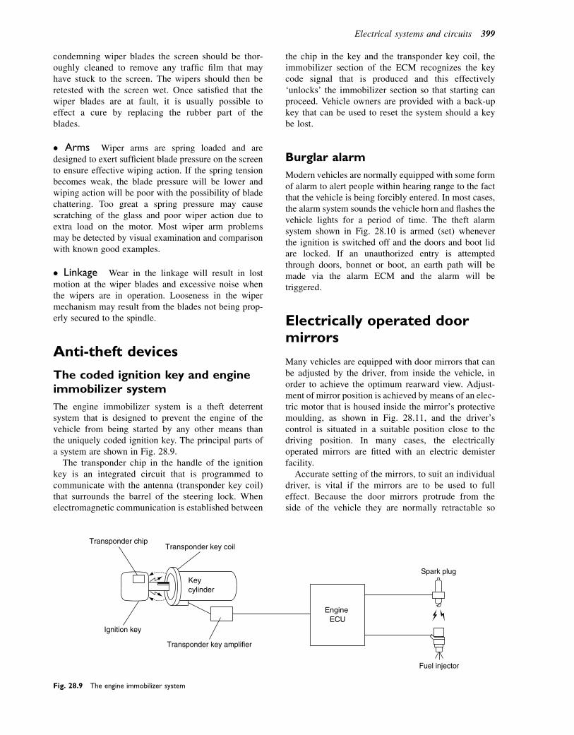
condemning wiper blades the screen should be thor-oughly cleaned to remove any traffic film that mayhave stuck to the screen. The wipers should then beretested with the screen wet. Once satisfied that thewiper blades are at fault, it is usually possible toeffect a cure by replacing the rubber part of theblades.
� Arms Wiper arms are spring loaded and aredesigned to exert sufficient blade pressure on the screento ensure effective wiping action. If the spring tensionbecomes weak, the blade pressure will be lower andwiping action will be poor with the possibility of bladechattering. Too great a spring pressure may causescratching of the glass and poor wiper action due toextra load on the motor. Most wiper arm problemsmay be detected by visual examination and comparisonwith known good examples.
� Linkage Wear in the linkage will result in lostmotion at the wiper blades and excessive noise whenthe wipers are in operation. Looseness in the wipermechanism may result from the blades not being prop-erly secured to the spindle.
Anti-theft devices
The coded ignition key and engineimmobilizer system
The engine immobilizer system is a theft deterrentsystem that is designed to prevent the engine of thevehicle from being started by any other means thanthe uniquely coded ignition key. The principal parts ofa system are shown in Fig. 28.9.
The transponder chip in the handle of the ignitionkey is an integrated circuit that is programmed tocommunicate with the antenna (transponder key coil)that surrounds the barrel of the steering lock. Whenelectromagnetic communication is established between
the chip in the key and the transponder key coil, theimmobilizer section of the ECM recognizes the keycode signal that is produced and this effectively‘unlocks’ the immobilizer section so that starting canproceed. Vehicle owners are provided with a back-upkey that can be used to reset the system should a keybe lost.
Burglar alarm
Modern vehicles are normally equipped with some formof alarm to alert people within hearing range to the factthat the vehicle is being forcibly entered. In most cases,the alarm system sounds the vehicle horn and flashes thevehicle lights for a period of time. The theft alarmsystem shown in Fig. 28.10 is armed (set) wheneverthe ignition is switched off and the doors and boot lidare locked. If an unauthorized entry is attemptedthrough doors, bonnet or boot, an earth path will bemade via the alarm ECM and the alarm will betriggered.
Electrically operated doormirrors
Many vehicles are equipped with door mirrors that canbe adjusted by the driver, from inside the vehicle, inorder to achieve the optimum rearward view. Adjust-ment of mirror position is achieved by means of an elec-tric motor that is housed inside the mirror’s protectivemoulding, as shown in Fig. 28.11, and the driver’scontrol is situated in a suitable position close to thedriving position. In many cases, the electricallyoperated mirrors are fitted with an electric demisterfacility.
Accurate setting of the mirrors, to suit an individualdriver, is vital if the mirrors are to be used to fulleffect. Because the door mirrors protrude from theside of the vehicle they are normally retractable so
Transponder chipTransponder key coil
Keycylinder
Engine ECU
Spark plug
Fuel injector
Transponder key amplifier
Ignition key
Fig. 28.9 The engine immobilizer system
Electrical systems and circuits 399
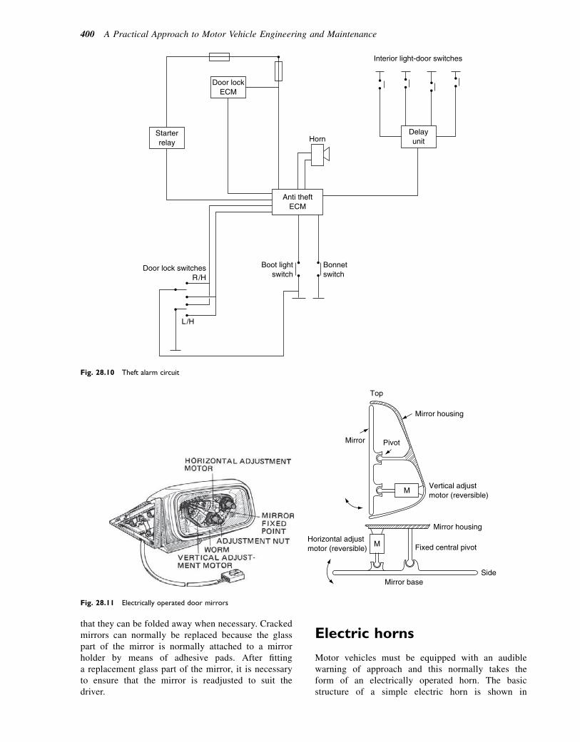
that they can be folded away when necessary. Crackedmirrors can normally be replaced because the glasspart of the mirror is normally attached to a mirrorholder by means of adhesive pads. After fittinga replacement glass part of the mirror, it is necessaryto ensure that the mirror is readjusted to suit thedriver.
Electric horns
Motor vehicles must be equipped with an audiblewarning of approach and this normally takes theform of an electrically operated horn. The basicstructure of a simple electric horn is shown in
Door lock ECM
Starter relay
Door lock switches R/H
Boot light switch
Bonnet switch
Horn
Interior light-door switches
Delay unit
Anti theft ECM
Fig. 28.10 Theft alarm circuit
Top
Mirror Pivot
Horizontal adjust motor (reversible) Fixed central pivot
Mirror housing
Mirror housing
Vertical adjust motor (reversible)
Mirror base Side
M
M
Fig. 28.11 Electrically operated door mirrors
400 A Practical Approach to Motor Vehicle Engineering and Maintenance
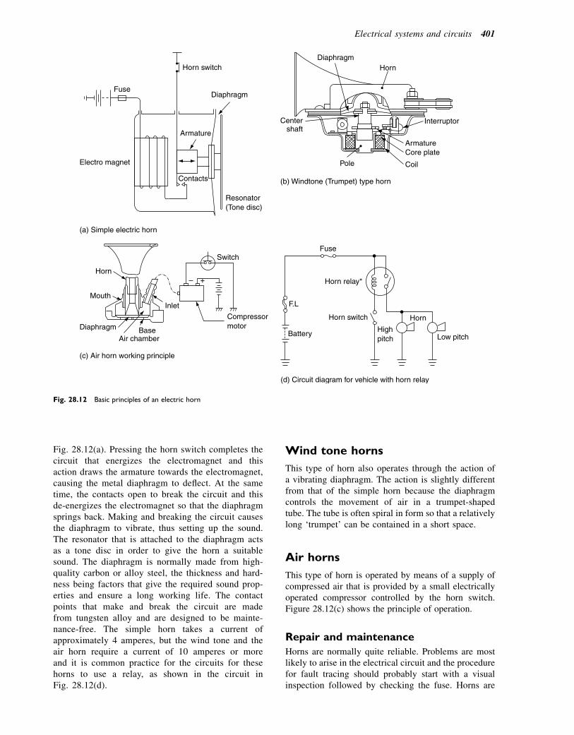
Fig. 28.12(a). Pressing the horn switch completes thecircuit that energizes the electromagnet and thisaction draws the armature towards the electromagnet,causing the metal diaphragm to deflect. At the sametime, the contacts open to break the circuit and thisde-energizes the electromagnet so that the diaphragmsprings back. Making and breaking the circuit causesthe diaphragm to vibrate, thus setting up the sound.The resonator that is attached to the diaphragm actsas a tone disc in order to give the horn a suitablesound. The diaphragm is normally made from high-quality carbon or alloy steel, the thickness and hard-ness being factors that give the required sound prop-erties and ensure a long working life. The contactpoints that make and break the circuit are madefrom tungsten alloy and are designed to be mainte-nance-free. The simple horn takes a current ofapproximately 4 amperes, but the wind tone and theair horn require a current of 10 amperes or moreand it is common practice for the circuits for thesehorns to use a relay, as shown in the circuit inFig. 28.12(d).
Wind tone horns
This type of horn also operates through the action ofa vibrating diaphragm. The action is slightly differentfrom that of the simple horn because the diaphragmcontrols the movement of air in a trumpet-shapedtube. The tube is often spiral in form so that a relativelylong ‘trumpet’ can be contained in a short space.
Air horns
This type of horn is operated by means of a supply ofcompressed air that is provided by a small electricallyoperated compressor controlled by the horn switch.Figure 28.12(c) shows the principle of operation.
Repair and maintenance
Horns are normally quite reliable. Problems are mostlikely to arise in the electrical circuit and the procedurefor fault tracing should probably start with a visualinspection followed by checking the fuse. Horns are
(a) Simple electric horn
Resonator (Tone disc)
Electro magnet
Fuse
Horn switch
Diaphragm
Armature
Contacts
Diaphragm Horn
Interruptor
Armature Core plate
Coil Pole
Center shaft
(b) Windtone (Trumpet) type horn
Horn
Mouth
Diaphragm Base Air chamber
Inlet
Compressor motor
Switch
– +
(c) Air horn working principle
Horn relay*
Fuse
Horn switch
Battery High pitch
F.L
Horn
Low pitch
(d) Circuit diagram for vehicle with horn relay
Fig. 28.12 Basic principles of an electric horn
Electrical systems and circuits 401

normally secured to the vehicle structure by means ofa flexible bracket, the purpose of which is to preventvehicle vibrations from distorting the quality of thesound emitted by the horn. This is a point to notewhen considering the fitment of a different type ofhorn.
Learning task
Inspect the horn installations on several differentvehicles. Pay particular attention to the fixing bracketand the type of horn. With the aid of the notes in thisbook, identify the type of horn in each case and thenlook up the vehicle details to compare your resultwith the horn details provided by the vehicle maker.
Electrically operated windows
Electrically operated windows are commonly used inmany types of vehicle. The two systems, illustrated inFig. 28.13, make use of reversible electric motors.The mechanism that is used to raise and lower thewindows is known as the regulator. In Fig. 28.13(a),the regulator is operated by a small gear on the motorshaft that engages with a quadrant gear on the arm ofthe regulator. Rotation of the motor armature causesa semi-rotary action of the quadrant. This semi-rotaryaction is converted into linear motion by the regulatormechanism. The system shown in Fig. 28.13(b) makesuse of cables that are wound on a drum that is driven bythe operating motor. In both cases, the electric motorsare of the permanent magnet type. The permanentmagnet motor is reversible via the switching systemand this permits the windows to be operated asrequired. An electrically operated window circuit nor-mally contains a thermally operated switch to protectthe circuit in the event of severe icing or other condition
that may lead to an excessive load on the motors andwinding mechanism.
Lighting
The main purpose of lights on a vehicle is to enable thedriver to see and for other road users to be able to seethe vehicle after dark and in other conditions of poorvisibility. In the UK there are legal requirements forthe lights that must be fitted. In summary, theserequirements are:
1. Headlamps (minimum of two, one each side)2. Side, rear, and number plate lamps3. Direction indicator lamps (flashers)4. Stop lamps (brake lights)5. Rear fog lamp (at least one).
All of these lamps must be maintained in workingcondition, including proper alignment.
Lighting regulations
The law relating to vehicle lights is quite complicatedand you are advised to check the regulations to ensurethat you understand them. This is particularly importantwhen fitting extra lights to a vehicle.
Bulbs
The main source of light for the lamps listed above is thetraditional bulb. Electric current in the bulb (lamp) fila-ment causes the filament to heat up and give out whitishlight. Where other colours are required, for example forstop and tail lights, the lamp lens is made from colouredmaterial. Figure 28.14 shows two commonly usedtypes of bulbs.
Power window regulator
Door control relay
Master switch
Sub-switch
Courtesy switch
Junction block
(a)
Fig. 28.13 Electrically operated windows.
(Reproduced with the kind permission of Ford
Motor Company Limited.)
402 A Practical Approach to Motor Vehicle Engineering and Maintenance

Ordinary twin-filament headlamp bulb
The filaments are made from tungsten wire and theglass bulb is often filled with an inert gas such asargon. This permits the filament to operate at a highertemperature and increases the reliability. One of thefilaments provides the main beam and the other
filament, which is placed a little above centre,provides the dipped beam. The effect is shown inFig. 28.15.
In order to locate the bulb accurately in the lampreflector, the metal base of the bulb is equipped witha notch, as shown in Fig. 28.16.
1 Window glass 2 Glass stop damper 3 Mounting screw (4 off) 4 Forward runner 5 Friction pad 6 Glass clamp screw 7 Motor assembly 8 Cable 9 Rear runner
1
9 8
2
3
4
5
6
7
M76 4004
LH regulator shown. RH similar (b)
Power window motor
(Front LH)
Power window main switch (Front LH)
Power window
main relay
: Power window switch (Front RH)
: Power window switch (Rear RH)
: Power window switch (Rear LH)
Battery
Door lock control relay
Door lock motor
IG switch
Power window motor
(Front RH)
Power window motor
(Rear RH)
M M
M 1
1
2
2
M
Power window motor
(Rear LH)
3
3
M
M
M
M
M
(c)
Fig. 28.13 Electrically operated windows (continued).
Electrical systems and circuits 403
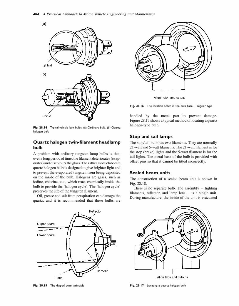
Quartz halogen twin-filament headlampbulb
A problem with ordinary tungsten lamp bulbs is that,over a long period of time, the filament deteriorates (evap-orates) and discolours theglass. The rathermore elaboratequartz halogen bulb is designed to give brighter light andto prevent the evaporated tungsten from being depositedon the inside of the bulb. Halogens are gases, such asiodine, chlorine, etc., which react chemically inside thebulb to provide the ‘halogen cycle’. The ‘halogen cycle’preserves the life of the tungsten filament.
Oil, grease and salt from perspiration can damage thequartz, and it is recommended that these bulbs are
handled by the metal part to prevent damage.Figure 28.17 shows a typical method of locating a quartzhalogen-type bulb.
Stop and tail lamps
The stop/tail bulb has two filaments. They are normally21-watt and 5-watt filaments. The 21-watt filament is forthe stop (brake) lights and the 5-watt filament is for thetail lights. The metal base of the bulb is provided withoffset pins so that it cannot be fitted incorrectly.
Sealed beam units
The construction of a sealed beam unit is shown inFig. 28.18.
There is no separate bulb. The assembly e lightingfilaments, reflector, and lamp lens e is a single unit.During manufacture, the inside of the unit is evacuated
Fig. 28.14 Typical vehicle light bulbs. (a) Ordinary bulb. (b) Quartz
halogen bulb
Fig. 28.15 The dipped beam principle
Fig. 28.16 The location notch in the bulb base e regular type
Fig. 28.17 Locating a quartz halogen bulb
404 A Practical Approach to Motor Vehicle Engineering and Maintenance
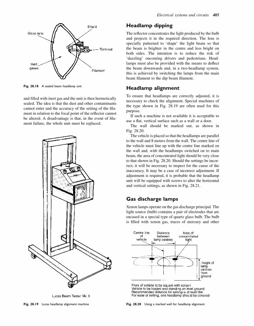
and filled with inert gas and the unit is then hermeticallysealed. The idea is that the dust and other contaminantscannot enter and the accuracy of the setting of the fila-ment in relation to the focal point of the reflector cannotbe altered. A disadvantage is that, in the event of fila-ment failure, the whole unit must be replaced.
Headlamp dipping
The reflector concentrates the light produced by the bulband projects it in the required direction. The lens isspecially patterned to ‘shape’ the light beam so thatthe beam is brighter in the centre and less bright onboth sides. The intention is to reduce the risk of‘dazzling’ oncoming drivers and pedestrians. Head-lamps must also be provided with the means to deflectthe beam downwards and, in a two-headlamp system,this is achieved by switching the lamps from the mainbeam filament to the dip beam filament.
Headlamp alignment
To ensure that headlamps are correctly adjusted, it isnecessary to check the alignment. Special machines ofthe type shown in Fig. 28.19 are often used for thispurpose.
If such a machine is not available it is acceptable touse a flat, vertical surface such as a wall or a door.
The wall should be marked out, as shown inFig. 28.20.
The vehicle is placed so that the headlamps are parallelto the wall and 8 metres from the wall. The centre line ofthe vehicle must line up with the centre line marked onthe wall and, with the headlamps switched on to mainbeam, the area of concentrated light should be very closeto that shown in Fig. 28.20. Should the settings be incor-rect, it will be necessary to inspect for the cause of theinaccuracy. It may be a case of incorrect adjustment. Ifadjustment is required, it is probable that the headlampunit will be equipped with screws to alter the horizontaland vertical settings, as shown in Fig. 28.21.
Gas discharge lamps
Xenon lamps operate on the gas discharge principal. Thelight source (bulb) contains a pair of electrodes that areencased in a special type of quartz glass bulb. The bulbis filled with xenon gas, traces of mercury and other
Fig. 28.19 Lucas headlamp alignment machine Fig. 28.20 Using a marked wall for headlamp alignment
Fig. 28.18 A sealed beam headlamp unit
Electrical systems and circuits 405
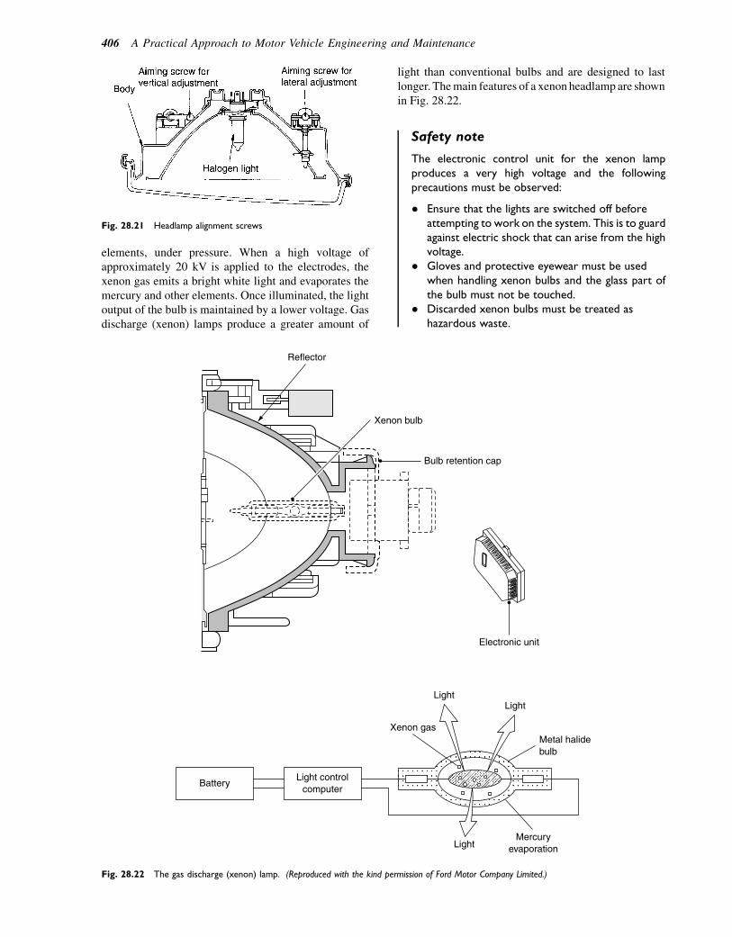
elements, under pressure. When a high voltage ofapproximately 20 kV is applied to the electrodes, thexenon gas emits a bright white light and evaporates themercury and other elements. Once illuminated, the lightoutput of the bulb is maintained by a lower voltage. Gasdischarge (xenon) lamps produce a greater amount of
light than conventional bulbs and are designed to lastlonger. Themain features of a xenon headlamp are shownin Fig. 28.22.
Safety note
The electronic control unit for the xenon lampproduces a very high voltage and the followingprecautions must be observed:
� Ensure that the lights are switched off beforeattempting to work on the system. This is to guardagainst electric shock that can arise from the highvoltage.
� Gloves and protective eyewear must be usedwhen handling xenon bulbs and the glass part ofthe bulb must not be touched.
� Discarded xenon bulbs must be treated ashazardous waste.
BatteryLight control
computer
Xenon gas
LightLight
Light
Metal halidebulb
Mercuryevaporation
Electronic unit
Reflector
Xenon bulb
Bulb retention cap
Fig. 28.22 The gas discharge (xenon) lamp. (Reproduced with the kind permission of Ford Motor Company Limited.)
Fig. 28.21 Headlamp alignment screws
406 A Practical Approach to Motor Vehicle Engineering and Maintenance

Vehicles that are equipped with xenon lamps mustalso be equipped with a means of automaticallyadjusting the lamps to prevent dazzling of oncomingdrivers.
Headlight and rear fog light circuit
In the circuit shown in Fig. 28.23, the rear fog lampcircuit is fed from the main light switch. The purposeof the rear fog lamp is to make the presence of the
vehicle more visible in difficult driving conditions.The headlamps are connected in parallel so thatfailure of one lamp does not lead to failure of theothers.
Direction indicators
Direction indicator lights (flashers) are required so thatthe driver can indicate any intended manoeuvre.Figure 28.24 shows a typical indicator lamp circuit.
Fig. 28.23 Headlamp and rear fog lamp circuit
Fig. 28.24 Indicator lamp circuit
Electrical systems and circuits 407

The ‘flasher’ unit is designed so that the frequency offlashes is not less than 60 per minute and not morethan 120 per minute. The circuit is also designed sothat failure of an indicator lamp will lead to an increasedfrequency of flashing and the driver will notice this atthe warning light.
The ‘flasher’ unit
The unit shown in Fig. 28.24 is marked 8FL. This isa Lucas unit that operates on the basis of thermalexpansion and contraction of a metal strip. The flasherunit shown in Fig. 28.25 employs a capacitor anda relay to provide the flashing action. Examination ofthe circuit diagram shown in Fig. 28.25 shows thatthe contact points are normally at rest in the closedposition. When the indicator switch is moved to indi-cate a turn, to left or right, current flows to the indicatorlamps, through the upper winding of the relay. Thiscurrent energizes the relay and opens the contactpoints, the current flow is interrupted, and the lamps‘go out’. As the lamps go out, the contact points closeand the lights ‘come on’ again. This happens ata frequency of approximately 90 flashes per minuteand the timing of the flash rate is controlled by thecapacitor.
Circuits and circuit principles
Circuit (wiring) diagrams
A complete circuit is needed for the flow of electriccurrent. Figure 28.26 shows two diagrams of a motor ina circuit. Should the fuse be blown, the circuit is incom-plete, current will not flow, and the motor will not run. Inthe right-hand diagram, the fuse has been replaced. Thecircuit is now complete and the motor will run. Basicelectrical principles such as this are fundamental togood work on electronic systems because much of thetesting of electronic systems requires checking of circuitsto ensure that they are complete.
It is essential to be able to understand and followcircuit diagrams and this requires a knowledge of circuitsymbols. There is a set of standard circuit symbols,some of which are shown in Fig. 28.27.
However, non-standard symbols of the type shownin Fig. 28.28 are sometimes used and this can causeconfusion. Fortunately, when non-standard symbols
Fig. 28.25 Capacitor and relay flasher unit and circuit. (a) Con-
struction of the flasher units. (b) Circuits for the two types of flasher
unit
Fig. 28.26 An electric circuit
408 A Practical Approach to Motor Vehicle Engineering and Maintenance
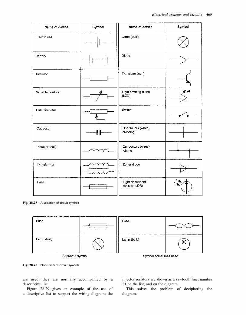
are used, they are normally accompanied by adescriptive list.
Figure 28.29 gives an example of the use ofa descriptive list to support the wiring diagram; the
injector resistors are shown as a sawtooth line, number21 on the list, and on the diagram.
This solves the problem of deciphering thediagram.
Fig. 28.27 A selection of circuit symbols
Fig. 28.28 Non-standard circuit symbols
Electrical systems and circuits 409
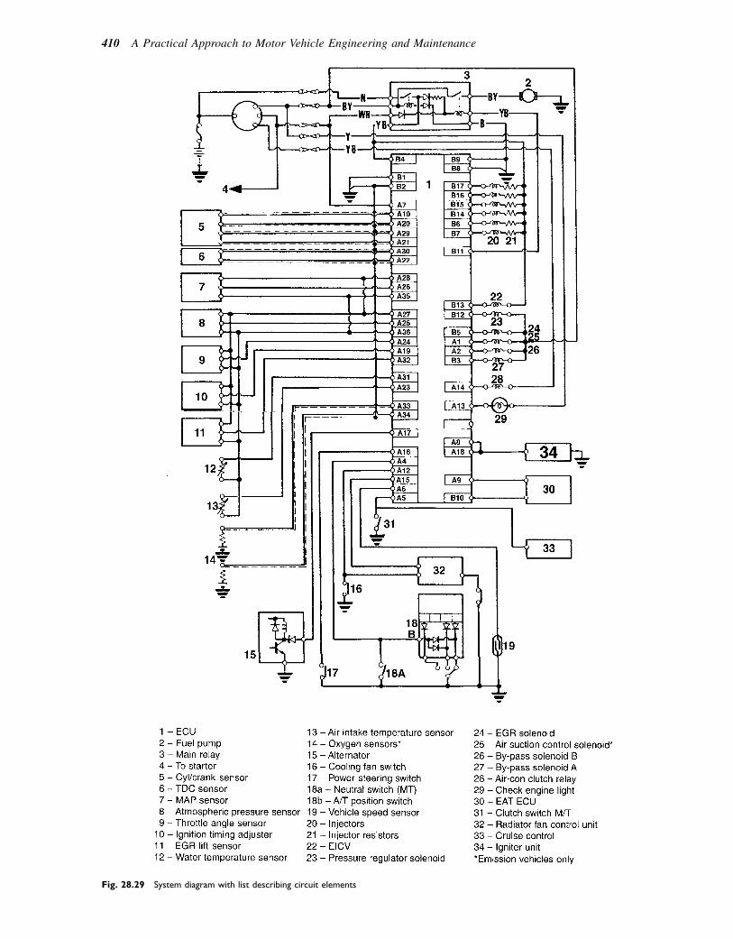
Fig. 28.29 System diagram with list describing circuit elements
410 A Practical Approach to Motor Vehicle Engineering and Maintenance
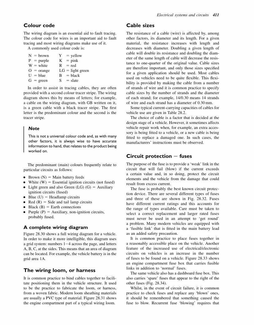
Colour code
The wiring diagram is an essential aid to fault tracing.The colour code for wires is an important aid to faulttracing and most wiring diagrams make use of it.
A commonly used colour code is:
N 5 brown Y 5 yellowP 5 purple K 5 pinkW 5 white R 5 redO 5 orange LG 5 light greenU 5 blue B 5 blackG 5 green S 5 slate
In order to assist in tracing cables, they are oftenprovided with a second colour tracer stripe. The wiringdiagram shows this by means of letters; for example,a cable on the wiring diagram, with GB written on it,is a green cable with a black tracer stripe. The firstletter is the predominant colour and the second is thetracer stripe.
Note
This is not a universal colour code and, as with manyother factors, it is always wise to have accurateinformation to hand, that relates to the product beingworked on.
The predominant (main) colours frequently relate toparticular circuits as follows:
� Brown (N) 5 Main battery feeds� White (W) 5 Essential ignition circuits (not fused)� Light green and also Green (LG) (G) 5 Auxiliary
ignition circuits (fused)� Blue (U) 5 Headlamp circuits� Red (R) 5 Side and tail lamp circuits� Black (B) 5 Earth connections� Purple (P) 5 Auxiliary, non-ignition circuits,
probably fused.
A complete wiring diagram
Figure 28.30 shows a full wiring diagram for a vehicle.In order to make it more intelligible, this diagram usesa grid system: numbers 1e4 across the page, and lettersA, B, C, at the sides. This means that an area of diagramcan be located. For example, the vehicle battery is in thegrid area 1A.
The wiring loom, or harness
It is common practice to bind cables together to facili-tate positioning them in the vehicle structure. It usedto be the practice to fabricate the loom, or harness,from a woven fabric. Modern loom sheathing materialsare usually a PVC type of material. Figure 28.31 showsthe engine compartment part of a typical wiring loom.
Cable sizes
The resistance of a cable (wire) is affected by, amongother factors, its diameter and its length. For a givenmaterial, the resistance increases with length anddecreases with diameter. Doubling a given length ofcable will double its resistance and doubling the diam-eter of the same length of cable will decrease the resis-tance to one-quarter of the original value. Cable sizesare therefore important, and only those sizes specifiedfor a given application should be used. Most cablesused on vehicles need to be quite flexible. This flexi-bility is provided by making the cable from a numberof strands of wire and it is common practice to specifycable sizes by the number of strands and the diameterof each strand; for example, 14/0.30 means 14 strandsof wire and each strand has a diameter of 0.30mm.
Some typical current-carrying capacities of cables forvehicle use are given in Table 28.2.
The choice of cable is a factor that is decided at thedesign stage of a vehicle. However, it sometimes affectsvehicle repair work when, for example, an extra acces-sory is being fitted to a vehicle, or a new cable is beingfitted to replace a damaged one. In such cases, themanufacturers’ instructions must be observed.
Circuit protection e fuses
The purpose of the fuse is to provide a ‘weak’ link in thecircuit that will fail (blow) if the current exceedsa certain value and, in so doing, protect the circuitelements and the vehicle from the damage that couldresult from excess current.
The fuse is probably the best known circuit protec-tion device. There are several different types of fusesand three of these are shown in Fig. 28.32. Fuseshave different current ratings and this accounts forthe range of types available. Care must be taken toselect a correct replacement and larger rated fusesmust never be used in an attempt to ‘get round’a problem. Many modern vehicles are equipped witha ‘fusible link’ that is fitted in the main battery leadas an added safety precaution.
It is common practice to place fuses together ina reasonably accessible place on the vehicle. Anotherfeature of the increased use of electrical/electroniccircuits on vehicles is an increase in the numberof fuses to be found on a vehicle. Figure 28.33 showsan engine compartment fuse box that carries fusiblelinks in addition to ‘normal’ fuses.
The same vehicle also has a dashboard fuse box. Thisalso carries ‘spare’ fuses that appear to the right of theother fuses (Fig. 28.34).
Whilst, in the event of circuit failure, it is commonpractice to check fuses and replace any ‘blown’ ones,it should be remembered that something caused thefuse to blow. Recurrent fuse ‘blowing’ requires that
Electrical systems and circuits 411
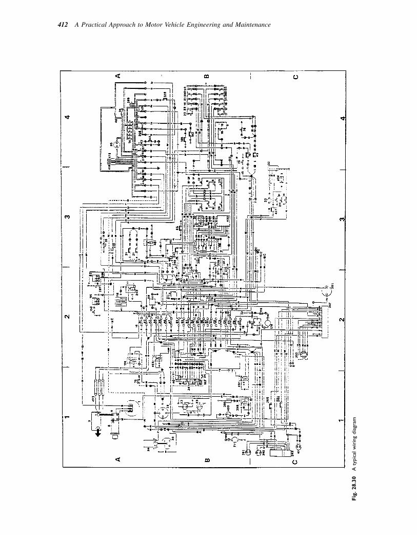
Fig.28.30
Atypicalwiringdiagram
412 A Practical Approach to Motor Vehicle Engineering and Maintenance

circuits should be checked to ascertain the cause of theexcess current that is causing the failure.
The circuit breaker
The thermal circuit breaker relies for its operation on theprinciple of the ‘bimetallic strip’. In Fig. 28.35, thebimetal strip carries the current between the terminalsof the circuit breaker. Excess current, above that forwhich the circuit is designed, will cause the temperatureof the bimetal strip to rise to a level where it will curveand cause the contacts to separate. This will open thecircuit and current will cease to flow. When the
temperature of the bimetal strip falls the circuit willbe remade. This action leads to intermittent functioningof the circuit, which will continue until the fault is recti-fied. An application may be of a 7.5 ampere circuitbreaker to protect a door lock circuit. The advantageof the circuit breaker, over a fuse, is that the circuitbreaker can be reused.
Fig. 28.31 Engine compartment wiring
loom
Table 28.2 Cable current-carrying capacities and use
Size of cable Current rating Typical use
14/0.30 8.75 amps Side and tail lamps
28/0.30 17.5 amps Headlamps
120/0.30 60 amps Alternator to batteryFig. 28.32 Fuse types
Electrical systems and circuits 413
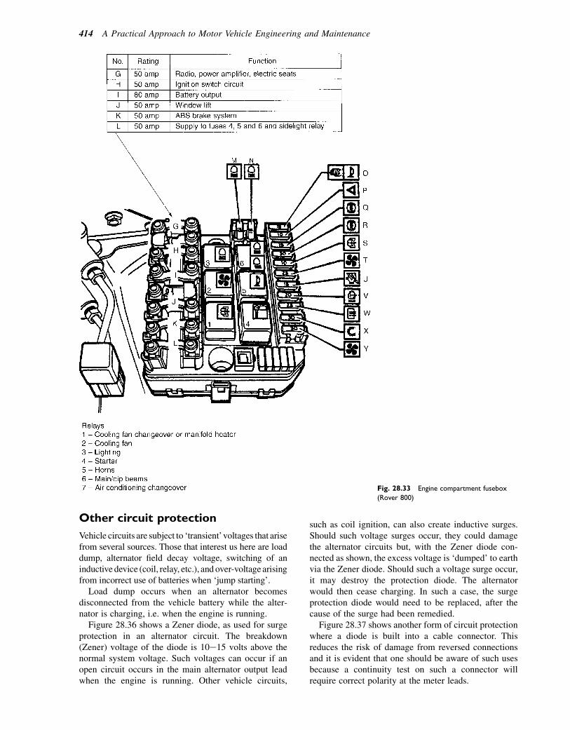
Other circuit protection
Vehicle circuits are subject to ‘transient’voltages that arisefrom several sources. Those that interest us here are loaddump, alternator field decay voltage, switching of aninductive device (coil, relay, etc.), and over-voltage arisingfrom incorrect use of batteries when ‘jump starting’.
Load dump occurs when an alternator becomesdisconnected from the vehicle battery while the alter-nator is charging, i.e. when the engine is running.
Figure 28.36 shows a Zener diode, as used for surgeprotection in an alternator circuit. The breakdown(Zener) voltage of the diode is 10e15 volts above thenormal system voltage. Such voltages can occur if anopen circuit occurs in the main alternator output leadwhen the engine is running. Other vehicle circuits,
such as coil ignition, can also create inductive surges.Should such voltage surges occur, they could damagethe alternator circuits but, with the Zener diode con-nected as shown, the excess voltage is ‘dumped’ to earthvia the Zener diode. Should such a voltage surge occur,it may destroy the protection diode. The alternatorwould then cease charging. In such a case, the surgeprotection diode would need to be replaced, after thecause of the surge had been remedied.
Figure 28.37 shows another form of circuit protectionwhere a diode is built into a cable connector. Thisreduces the risk of damage from reversed connectionsand it is evident that one should be aware of such usesbecause a continuity test on such a connector willrequire correct polarity at the meter leads.
Fig. 28.33 Engine compartment fusebox
(Rover 800)
414 A Practical Approach to Motor Vehicle Engineering and Maintenance
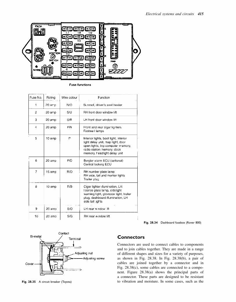
Connectors
Connectors are used to connect cables to componentsand to join cables together. They are made in a rangeof different shapes and sizes for a variety of purposes,as shown in Fig. 28.38. In Fig. 28.38(b), a pair ofcables are joined together by a connector and inFig. 28.38(c), some cables are connected to a compo-nent. Figure 28.38(a) shows the principal parts ofa connector. These parts are designed to be resistantto vibration and moisture. In some cases, such as the
Fig. 28.34 Dashboard fusebox (Rover 800)
Fig. 28.35 A circuit breaker (Toyota)
Electrical systems and circuits 415
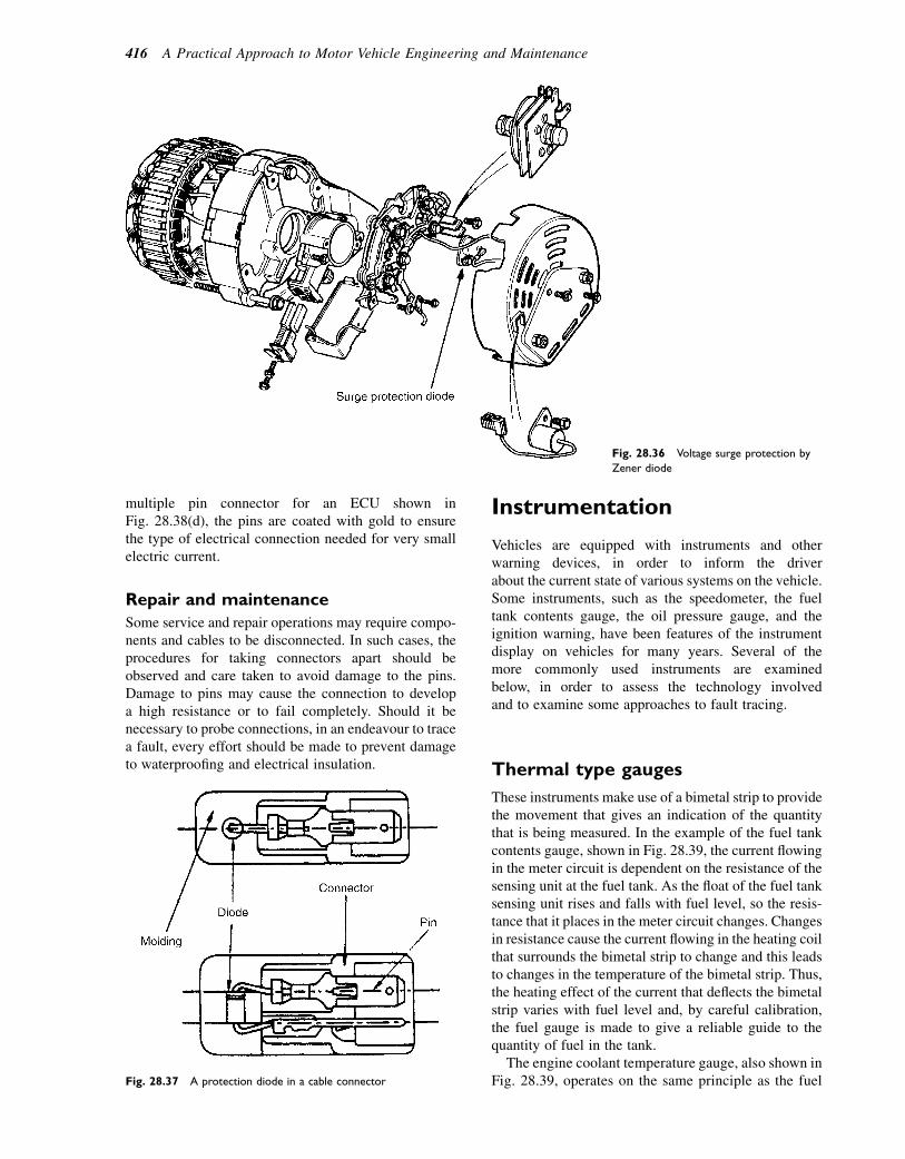
multiple pin connector for an ECU shown inFig. 28.38(d), the pins are coated with gold to ensurethe type of electrical connection needed for very smallelectric current.
Repair and maintenance
Some service and repair operations may require compo-nents and cables to be disconnected. In such cases, theprocedures for taking connectors apart should beobserved and care taken to avoid damage to the pins.Damage to pins may cause the connection to developa high resistance or to fail completely. Should it benecessary to probe connections, in an endeavour to tracea fault, every effort should be made to prevent damageto waterproofing and electrical insulation.
Instrumentation
Vehicles are equipped with instruments and otherwarning devices, in order to inform the driverabout the current state of various systems on the vehicle.Some instruments, such as the speedometer, the fueltank contents gauge, the oil pressure gauge, and theignition warning, have been features of the instrumentdisplay on vehicles for many years. Several of themore commonly used instruments are examinedbelow, in order to assess the technology involvedand to examine some approaches to fault tracing.
Thermal type gauges
These instruments make use of a bimetal strip to providethe movement that gives an indication of the quantitythat is being measured. In the example of the fuel tankcontents gauge, shown in Fig. 28.39, the current flowingin the meter circuit is dependent on the resistance of thesensing unit at the fuel tank. As the float of the fuel tanksensing unit rises and falls with fuel level, so the resis-tance that it places in the meter circuit changes. Changesin resistance cause the current flowing in the heating coilthat surrounds the bimetal strip to change and this leadsto changes in the temperature of the bimetal strip. Thus,the heating effect of the current that deflects the bimetalstrip varies with fuel level and, by careful calibration,the fuel gauge is made to give a reliable guide to thequantity of fuel in the tank.
The engine coolant temperature gauge, also shown inFig. 28.39, operates on the same principle as the fuel
Fig. 28.36 Voltage surge protection by
Zener diode
Fig. 28.37 A protection diode in a cable connector
416 A Practical Approach to Motor Vehicle Engineering and Maintenance
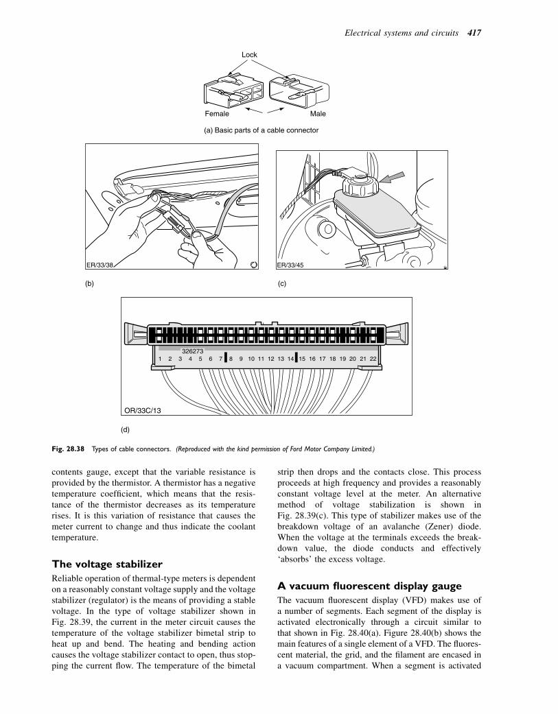
contents gauge, except that the variable resistance isprovided by the thermistor. A thermistor has a negativetemperature coefficient, which means that the resis-tance of the thermistor decreases as its temperaturerises. It is this variation of resistance that causes themeter current to change and thus indicate the coolanttemperature.
The voltage stabilizer
Reliable operation of thermal-type meters is dependenton a reasonably constant voltage supply and the voltagestabilizer (regulator) is the means of providing a stablevoltage. In the type of voltage stabilizer shown inFig. 28.39, the current in the meter circuit causes thetemperature of the voltage stabilizer bimetal strip toheat up and bend. The heating and bending actioncauses the voltage stabilizer contact to open, thus stop-ping the current flow. The temperature of the bimetal
strip then drops and the contacts close. This processproceeds at high frequency and provides a reasonablyconstant voltage level at the meter. An alternativemethod of voltage stabilization is shown inFig. 28.39(c). This type of stabilizer makes use of thebreakdown voltage of an avalanche (Zener) diode.When the voltage at the terminals exceeds the break-down value, the diode conducts and effectively‘absorbs’ the excess voltage.
A vacuum fluorescent display gauge
The vacuum fluorescent display (VFD) makes use ofa number of segments. Each segment of the display isactivated electronically through a circuit similar tothat shown in Fig. 28.40(a). Figure 28.40(b) shows themain features of a single element of a VFD. The fluores-cent material, the grid, and the filament are encased ina vacuum compartment. When a segment is activated
(a) Basic parts of a cable connector
MaleFemale
Lock
ER/33/38
(b) (c)
ER/33/45
(d)
1 2 3 4 5 6 7 8 9 10 11 12 13 14 15 16 17 18 19 20 21 22326273
OR/33C/13
Fig. 28.38 Types of cable connectors. (Reproduced with the kind permission of Ford Motor Company Limited.)
Electrical systems and circuits 417
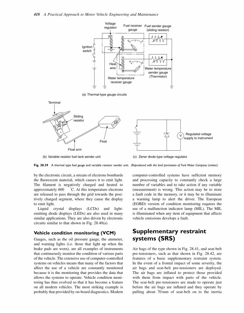
by the electronic circuit, a stream of electrons bombardsthe fluorescent material, which causes it to emit light.The filament is negatively charged and heated toapproximately 600 8C. At this temperature electronsare released to pass through the grid towards the posi-tively charged segment, where they cause the displayto emit light.
Liquid crystal displays (LCDs) and light-emitting diode displays (LEDs) are also used in manysimilar applications. They are also driven by electroniccircuits similar to that shown in Fig. 28.40(a).
Vehicle condition monitoring (VCM)
Gauges, such as the oil pressure gauge, the ammeter,and warning lights (i.e. those that light up when thebrake pads are worn), are all examples of instrumentsthat continuously monitor the condition of various partsof the vehicle. The extensive use of computer-controlledsystems on vehicles means that many of the factors thataffect the use of a vehicle are constantly monitoredbecause it is the monitoring that provides the data thatallows the systems to operate. Vehicle condition moni-toring has thus evolved so that it has become a featureon all modern vehicles. The most striking example isprobably that provided by on-board diagnostics. Modern
computer-controlled systems have sufficient memoryand processing capacity to constantly check a largenumber of variables and to take action if any variable(measurement) is wrong. This action may be to storea fault code in the memory, or it may be to illuminatea warning lamp to alert the driver. The European(EOBD) version of condition monitoring requires theuse of a malfunction indicator lamp (MIL). The MILis illuminated when any item of equipment that affectsvehicle emissions develops a fault.
Supplementary restraintsystems (SRS)
Air bags of the type shown in Fig. 28.41, and seat-beltpre-tensioners, such as that shown in Fig. 28.42, arefeatures of a basic supplementary restraint system.In the event of a frontal impact of some severity, theair bags and seat-belt pre-tensioners are deployed.The air bags are inflated to protect those providedwith them from impact with parts of the vehicle.The seat-belt pre-tensioners are made to operate justbefore the air bags are inflated and they operate bypulling about 70mm of seat-belt on to the inertia
Fuel sender gauge (sliding resistor)
Voltage regulator
Fuel receiver gauge
Water temperature sender gauge (Thermistor) Water temperature
receiver gauge
Heat wire
Ignition switch
E F
H C
(a) Thermal-type gauge circuits
V Regulated voltagesupply to instrument
(c) Zener diode type voltage regulator
Float
Float arm
Sliding resistor
Terminal
(b) Variable resistor fuel tank sender unit
Fig. 28.39 A thermal type fuel gauge and variable resistor sender unit. (Reproduced with the kind permission of Ford Motor Company Limited.)
418 A Practical Approach to Motor Vehicle Engineering and Maintenance
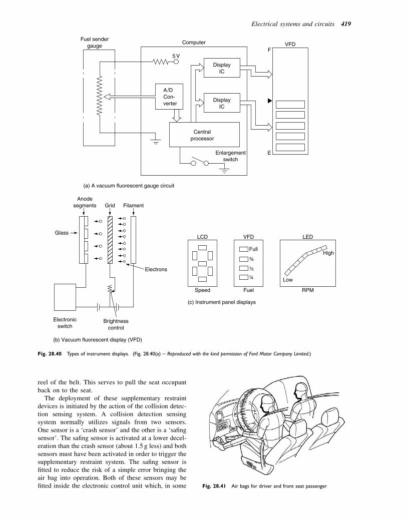
reel of the belt. This serves to pull the seat occupantback on to the seat.
The deployment of these supplementary restraintdevices is initiated by the action of the collision detec-tion sensing system. A collision detection sensingsystem normally utilizes signals from two sensors.One sensor is a ‘crash sensor’ and the other is a ‘safingsensor’. The safing sensor is activated at a lower decel-eration than the crash sensor (about 1.5 g less) and bothsensors must have been activated in order to trigger thesupplementary restraint system. The safing sensor isfitted to reduce the risk of a simple error bringing theair bag into operation. Both of these sensors may befitted inside the electronic control unit which, in some
(c) Instrument panel displays
VFD LCD LED
High
Low
Speed Fuel
Full
RPM
(b) Vacuum fluorescent display (VFD)
Grid Filament
Electrons
Brightness control
Electronic switch
Anode segments
Glass
(a) A vacuum fluorescent gauge circuit
Display IC
Display IC
Fuel sender gauge
Central processor
Enlargement switch
VFD
E
F Computer
Fig. 28.40 Types of instrument displays. (Fig. 28.40(a) e Reproduced with the kind permission of Ford Motor Company Limited.)
Fig. 28.41 Air bags for driver and front seat passenger
Electrical systems and circuits 419
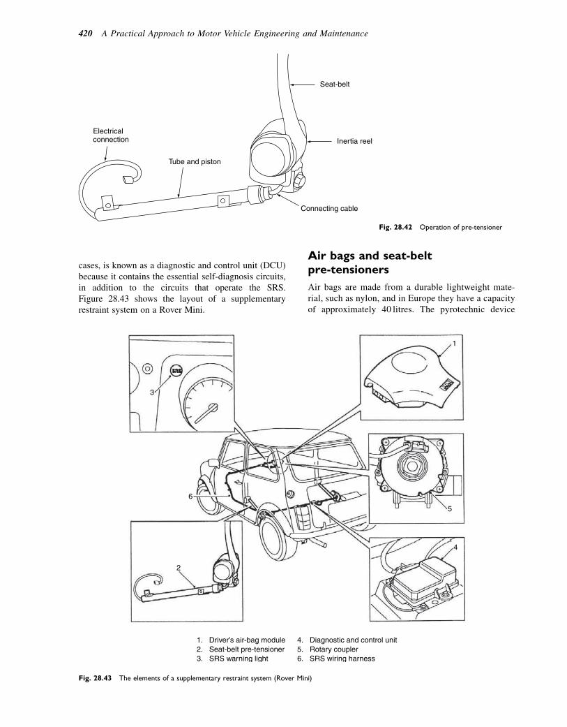
cases, is known as a diagnostic and control unit (DCU)because it contains the essential self-diagnosis circuits,in addition to the circuits that operate the SRS.Figure 28.43 shows the layout of a supplementaryrestraint system on a Rover Mini.
Air bags and seat-beltpre-tensioners
Air bags are made from a durable lightweight mate-rial, such as nylon, and in Europe they have a capacityof approximately 40 litres. The pyrotechnic device
Electrical connection
Tube and piston
Connecting cable
Inertia reel
Seat-belt
Fig. 28.42 Operation of pre-tensioner
3
2
6
1
5
4
Fig. 28.43 The elements of a supplementary restraint system (Rover Mini)
420 A Practical Approach to Motor Vehicle Engineering and Maintenance
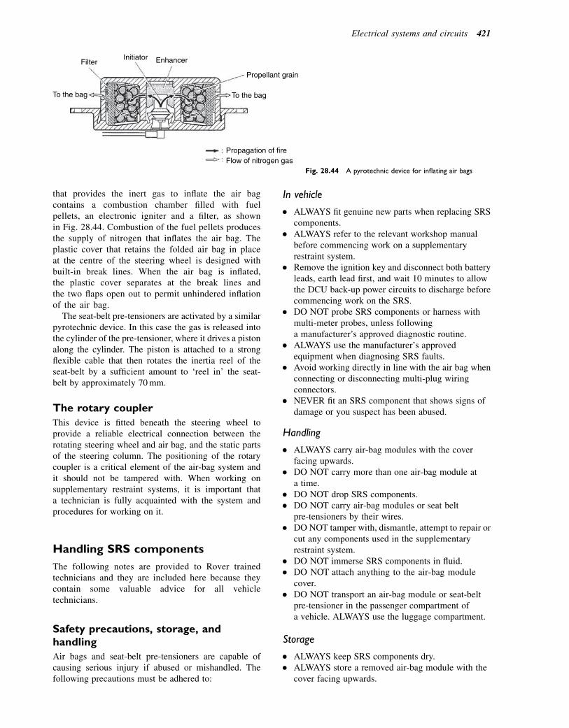
that provides the inert gas to inflate the air bagcontains a combustion chamber filled with fuelpellets, an electronic igniter and a filter, as shownin Fig. 28.44. Combustion of the fuel pellets producesthe supply of nitrogen that inflates the air bag. Theplastic cover that retains the folded air bag in placeat the centre of the steering wheel is designed withbuilt-in break lines. When the air bag is inflated,the plastic cover separates at the break lines andthe two flaps open out to permit unhindered inflationof the air bag.
The seat-belt pre-tensioners are activated by a similarpyrotechnic device. In this case the gas is released intothe cylinder of the pre-tensioner, where it drives a pistonalong the cylinder. The piston is attached to a strongflexible cable that then rotates the inertia reel of theseat-belt by a sufficient amount to ‘reel in’ the seat-belt by approximately 70mm.
The rotary coupler
This device is fitted beneath the steering wheel toprovide a reliable electrical connection between therotating steering wheel and air bag, and the static partsof the steering column. The positioning of the rotarycoupler is a critical element of the air-bag system andit should not be tampered with. When working onsupplementary restraint systems, it is important thata technician is fully acquainted with the system andprocedures for working on it.
Handling SRS components
The following notes are provided to Rover trainedtechnicians and they are included here because theycontain some valuable advice for all vehicletechnicians.
Safety precautions, storage, andhandling
Air bags and seat-belt pre-tensioners are capable ofcausing serious injury if abused or mishandled. Thefollowing precautions must be adhered to:
In vehicle
� ALWAYS fit genuine new parts when replacing SRScomponents.
� ALWAYS refer to the relevant workshop manualbefore commencing work on a supplementaryrestraint system.
� Remove the ignition key and disconnect both batteryleads, earth lead first, and wait 10 minutes to allowthe DCU back-up power circuits to discharge beforecommencing work on the SRS.
� DO NOT probe SRS components or harness withmulti-meter probes, unless followinga manufacturer’s approved diagnostic routine.
� ALWAYS use the manufacturer’s approvedequipment when diagnosing SRS faults.
� Avoid working directly in line with the air bag whenconnecting or disconnecting multi-plug wiringconnectors.
� NEVER fit an SRS component that shows signs ofdamage or you suspect has been abused.
Handling
� ALWAYS carry air-bag modules with the coverfacing upwards.
� DO NOT carry more than one air-bag module ata time.
� DO NOT drop SRS components.� DO NOT carry air-bag modules or seat belt
pre-tensioners by their wires.� DO NOT tamper with, dismantle, attempt to repair or
cut any components used in the supplementaryrestraint system.
� DO NOT immerse SRS components in fluid.� DO NOT attach anything to the air-bag module
cover.� DO NOT transport an air-bag module or seat-belt
pre-tensioner in the passenger compartment ofa vehicle. ALWAYS use the luggage compartment.
Storage
� ALWAYS keep SRS components dry.� ALWAYS store a removed air-bag module with the
cover facing upwards.
FilterInitiator Enhancer
Propellant grain
To the bag
Propagation of fireFlow of nitrogen gas
To the bag
Fig. 28.44 A pyrotechnic device for inflating air bags
Electrical systems and circuits 421
� DO NOT allow anything to rest on the air-bagmodule.
� ALWAYS place the air-bag module or pre-tensionerin the designated storage area.
� ALWAYS store the air-bag module on a flat, securesurface well away from electrical equipment orsources of high temperature.
Note
Air-bag modules and pyrotechnic seat-belt pre-tensioners are classed as explosive articles and, assuch, must be stored overnight in an approved,secure steel cabinet that is registered with the LocalAuthority.
Disposal of air-bag modules and pyrotechnicseat-belt pre-tensioners
If a vehicle that contains air bags and seat-belt pre-tensioners that have not been deployed (activated) isto be scrapped, the air bags and seat-belt pre-tensionersmust be rendered inoperable by activating them manu-ally prior to disposal. This procedure may only be per-formed in accordance with the manufacturer’sinstruction manual.
Learning tasks
1. Identify the headlamp alignment equipment that isused in your workplace. Study the instructionsfor use and consult with your training supervisorto arrange sessions when you will learn how touse the equipment.
2. Examine a number of vehicles and note theprocedures that must be followed in order toreplace headlamp bulbs and bulbs in any otherexternal lamps on the vehicles.
3. Examine a number of screen wiper blades and,with the aid of sketches and a few notes, explainthe procedure for replacing worn squeegees.
4. With the aid of workshop manuals, locate thefuse boxes on a number of vehicles. Makea note of the different types of fuses that youhave seen and discuss with your supervisor theprocedure for replacing blown fuses.
5. Locate the heated rear screen relay on a vehicleand write down an explanation as to why it isplaced where it is. Explain this to your trainingsupervisor.
6. Examine a number of vehicles to locate the posi-tion of the horn. Use the manual to find the posi-tion of the horn relay and fuse.
7. Describe the procedure for dealing with air bagswhen a repair operation entails removal ofa steering wheel.
Self-assessment questions1. The approximate electric current used by a 12-volt
wiper motor, when it is in proper operatingcondition, is:(a) 1.5e4 A(b) 15e40 A(c) 0.15e0.4 A(d) 6 watts.
2. Remote controllers for central locking are infraredor radio frequency devices. The source of energythat provides the power for the remote controldevice is:(a) an electromagnet in the key(b) a small battery in the key(c) static electricity(d) a thermionic valve.
3. Two additives that are added to water to makescreen washer fluid are:(a) liquid paraffin and salt(b) antifreeze and detergent(c) boiling point depressant and descaler(d) distilled water and rubber lubricant.
4. Regenerative braking of a screen wiper motor isachieved by:(a) a clamping action on the wiper mechanism(b) electrically connecting the two main brushes of
a permanent magnet motor(c) a mechanical brake on the wiper motor driving
gears(d) the back e.m.f. from the wiper control switch.
5. By what means is the self-parking action of wiperblades achieved:(a) a cam-operated trip switch at the motor
switches the motor off when the park positionis reached
(b) a mechanism that permits the driver to stop thewiper arms at any point on the screen
(c) a rheostat that is built into the switch circuit(d) a sensor built into the screen.
6. A wind tone horn circuit contains a relay:(a) to reduce power loss(b) because of the high current(c) to vibrate the diaphragm(d) to reduce arcing at the horn switch.
7. Instrument circuits require a steady voltage that isprovided by:(a) a relay(b) a voltage stabilizer(c) a field effect transistor(d) a separate battery.
8. Electrically operated windows are operated by:(a) linear motors(b) semi-rotary induction motors(c) reversible permanent magnet motors(d) powerful solenoids.
422 A Practical Approach to Motor Vehicle Engineering and Maintenance

9. Headlamps are connected:(a) in series(b) in parallel(c) by a Wheatstone bridge(d) by a failure mode analysis circuit.
10. Hazard warning lights:(a) make use of the direction indicator lamps circuit(b) operate in conjunction with the fuel circuit
inertia switch
(c) operate by causing the stop lamps to flash(d) use 5-watt MES bulbs.
11. List three factors that may cause scratching of thewindscreen.
12. Make a list of the possible causes of a weak spray ofwasher fluid from the jets on to the screen.
13. Describe a simple procedure to test a theft alarmsystem.
Electrical systems and circuits 423
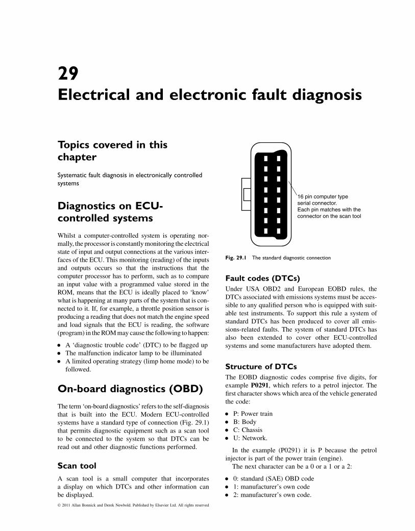
29Electrical and electronic fault diagnosis
Topics covered in thischapter
Systematic fault diagnosis in electronically controlledsystems
Diagnostics on ECU-controlled systems
Whilst a computer-controlled system is operating nor-mally, the processor is constantlymonitoring the electricalstate of input and output connections at the various inter-faces of the ECU. This monitoring (reading) of the inputsand outputs occurs so that the instructions that thecomputer processor has to perform, such as to comparean input value with a programmed value stored in theROM, means that the ECU is ideally placed to ‘know’what is happening at many parts of the system that is con-nected to it. If, for example, a throttle position sensor isproducing a reading that does not match the engine speedand load signals that the ECU is reading, the software(program) in theROMmay cause the following tohappen:
� A ‘diagnostic trouble code’ (DTC) to be flagged up� The malfunction indicator lamp to be illuminated� A limited operating strategy (limp home mode) to be
followed.
On-board diagnostics (OBD)
The term ‘on-board diagnostics’ refers to the self-diagnosisthat is built into the ECU. Modern ECU-controlledsystems have a standard type of connection (Fig. 29.1)that permits diagnostic equipment such as a scan toolto be connected to the system so that DTCs can beread out and other diagnostic functions performed.
Scan tool
A scan tool is a small computer that incorporatesa display on which DTCs and other information canbe displayed.
Fault codes (DTCs)
Under USA OBD2 and European EOBD rules, theDTCs associated with emissions systems must be acces-sible to any qualified person who is equipped with suit-able test instruments. To support this rule a system ofstandard DTCs has been produced to cover all emis-sions-related faults. The system of standard DTCs hasalso been extended to cover other ECU-controlledsystems and some manufacturers have adopted them.
Structure of DTCs
The EOBD diagnostic codes comprise five digits, forexample P0291, which refers to a petrol injector. Thefirst character shows which area of the vehicle generatedthe code:
� P: Power train� B: Body� C: Chassis� U: Network.
In the example (P0291) it is P because the petrolinjector is part of the power train (engine).
The next character can be a 0 or a 1 or a 2:
� 0: standard (SAE) OBD code� 1: manufacturer’s own code� 2: manufacturer’s own code.
16 pin computer typeserial connector.Each pin matches with theconnector on the scan tool
Fig. 29.1 The standard diagnostic connection
� 2011 Allan Bonnick and Derek Newbold. Published by Elsevier Ltd. All rights reserved
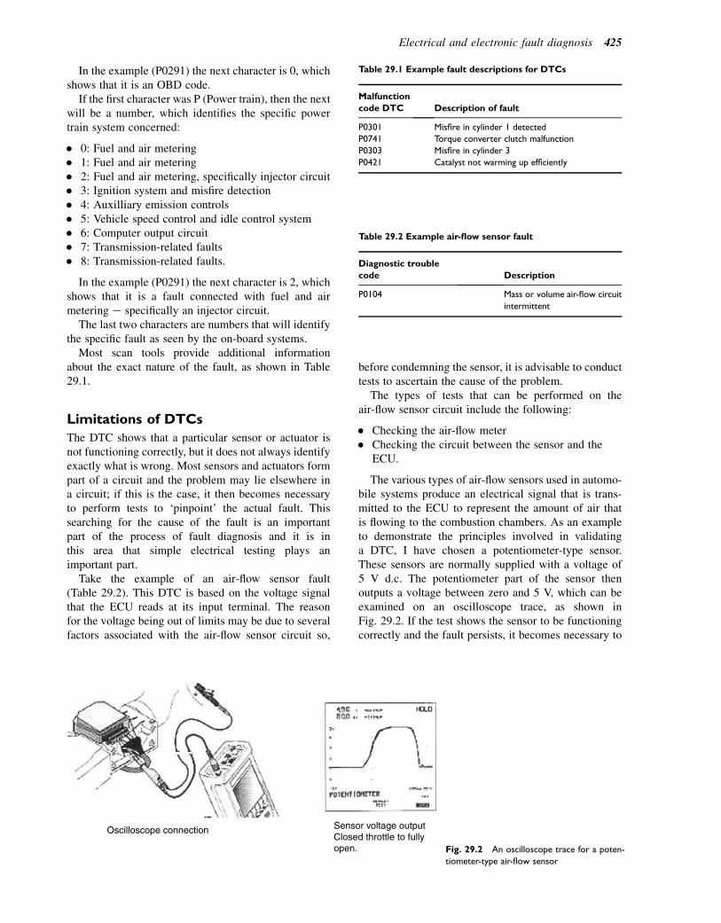
In the example (P0291) the next character is 0, whichshows that it is an OBD code.
If the first character was P (Power train), then the nextwill be a number, which identifies the specific powertrain system concerned:
� 0: Fuel and air metering� 1: Fuel and air metering� 2: Fuel and air metering, specifically injector circuit� 3: Ignition system and misfire detection� 4: Auxilliary emission controls� 5: Vehicle speed control and idle control system� 6: Computer output circuit� 7: Transmission-related faults� 8: Transmission-related faults.
In the example (P0291) the next character is 2, whichshows that it is a fault connected with fuel and airmetering e specifically an injector circuit.
The last two characters are numbers that will identifythe specific fault as seen by the on-board systems.
Most scan tools provide additional informationabout the exact nature of the fault, as shown in Table29.1.
Limitations of DTCs
The DTC shows that a particular sensor or actuator isnot functioning correctly, but it does not always identifyexactly what is wrong. Most sensors and actuators formpart of a circuit and the problem may lie elsewhere ina circuit; if this is the case, it then becomes necessaryto perform tests to ‘pinpoint’ the actual fault. Thissearching for the cause of the fault is an importantpart of the process of fault diagnosis and it is inthis area that simple electrical testing plays animportant part.
Take the example of an air-flow sensor fault(Table 29.2). This DTC is based on the voltage signalthat the ECU reads at its input terminal. The reasonfor the voltage being out of limits may be due to severalfactors associated with the air-flow sensor circuit so,
before condemning the sensor, it is advisable to conducttests to ascertain the cause of the problem.
The types of tests that can be performed on theair-flow sensor circuit include the following:
� Checking the air-flow meter� Checking the circuit between the sensor and the
ECU.
The various types of air-flow sensors used in automo-bile systems produce an electrical signal that is trans-mitted to the ECU to represent the amount of air thatis flowing to the combustion chambers. As an exampleto demonstrate the principles involved in validatinga DTC, I have chosen a potentiometer-type sensor.These sensors are normally supplied with a voltage of5 V d.c. The potentiometer part of the sensor thenoutputs a voltage between zero and 5 V, which can beexamined on an oscilloscope trace, as shown inFig. 29.2. If the test shows the sensor to be functioningcorrectly and the fault persists, it becomes necessary to
Table 29.2 Example air-flow sensor fault
Diagnostic trouble
code Description
P0104 Mass or volume air-flow circuit
intermittent
Oscilloscope connection Sensor voltage outputClosed throttle to fullyopen. Fig. 29.2 An oscilloscope trace for a poten-
tiometer-type air-flow sensor
Table 29.1 Example fault descriptions for DTCs
Malfunction
code DTC Description of fault
P0301 Misfire in cylinder 1 detected
P0741 Torque converter clutch malfunction
P0303 Misfire in cylinder 3
P0421 Catalyst not warming up efficiently
Electrical and electronic fault diagnosis 425
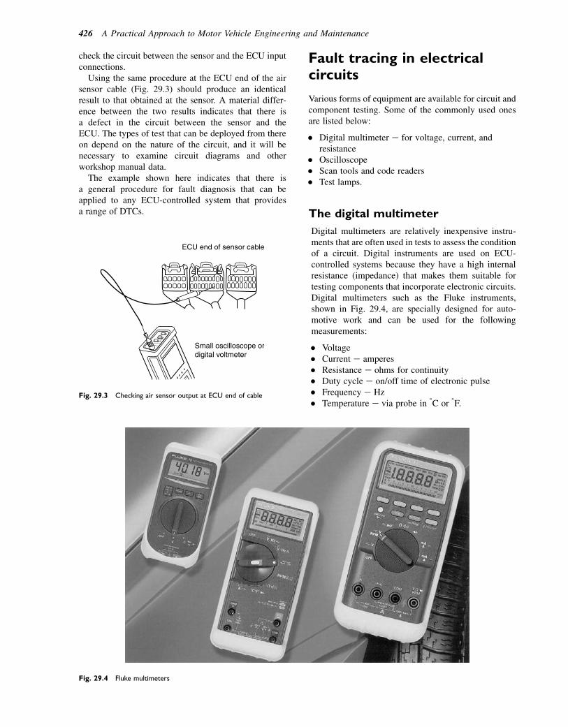
check the circuit between the sensor and the ECU inputconnections.
Using the same procedure at the ECU end of the airsensor cable (Fig. 29.3) should produce an identicalresult to that obtained at the sensor. A material differ-ence between the two results indicates that there isa defect in the circuit between the sensor and theECU. The types of test that can be deployed from thereon depend on the nature of the circuit, and it will benecessary to examine circuit diagrams and otherworkshop manual data.
The example shown here indicates that there isa general procedure for fault diagnosis that can beapplied to any ECU-controlled system that providesa range of DTCs.
Fault tracing in electricalcircuits
Various forms of equipment are available for circuit andcomponent testing. Some of the commonly used onesare listed below:
� Digital multimeter e for voltage, current, andresistance
� Oscilloscope� Scan tools and code readers� Test lamps.
The digital multimeter
Digital multimeters are relatively inexpensive instru-ments that are often used in tests to assess the conditionof a circuit. Digital instruments are used on ECU-controlled systems because they have a high internalresistance (impedance) that makes them suitable fortesting components that incorporate electronic circuits.Digital multimeters such as the Fluke instruments,shown in Fig. 29.4, are specially designed for auto-motive work and can be used for the followingmeasurements:
� Voltage� Current e amperes� Resistance e ohms for continuity� Duty cycle e on/off time of electronic pulse� Frequency e Hz� Temperature e via probe in 8C or 8F.
ECU end of sensor cable
Small oscilloscope ordigital voltmeter
Fig. 29.3 Checking air sensor output at ECU end of cable
Fig. 29.4 Fluke multimeters
426 A Practical Approach to Motor Vehicle Engineering and Maintenance
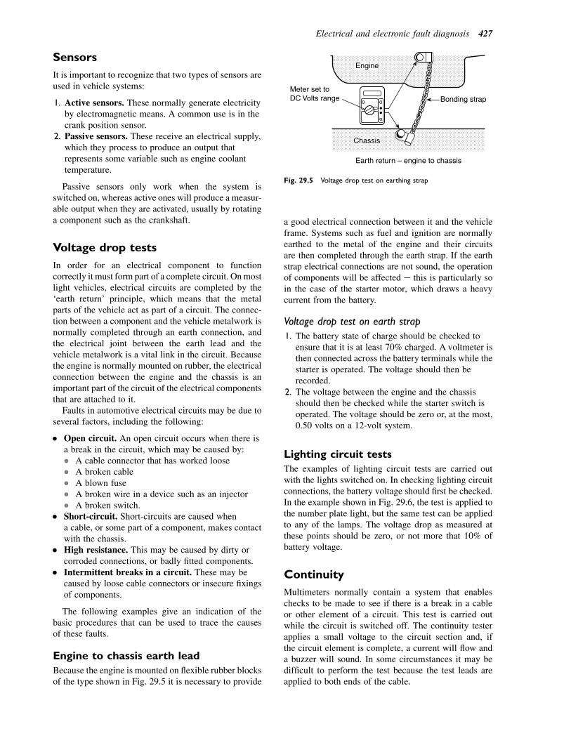
Sensors
It is important to recognize that two types of sensors areused in vehicle systems:
1. Active sensors. These normally generate electricityby electromagnetic means. A common use is in thecrank position sensor.
2. Passive sensors. These receive an electrical supply,which they process to produce an output thatrepresents some variable such as engine coolanttemperature.
Passive sensors only work when the system isswitched on, whereas active ones will produce a measur-able output when they are activated, usually by rotatinga component such as the crankshaft.
Voltage drop tests
In order for an electrical component to functioncorrectly it must form part of a complete circuit. Onmostlight vehicles, electrical circuits are completed by the‘earth return’ principle, which means that the metalparts of the vehicle act as part of a circuit. The connec-tion between a component and the vehicle metalwork isnormally completed through an earth connection, andthe electrical joint between the earth lead and thevehicle metalwork is a vital link in the circuit. Becausethe engine is normally mounted on rubber, the electricalconnection between the engine and the chassis is animportant part of the circuit of the electrical componentsthat are attached to it.
Faults in automotive electrical circuits may be due toseveral factors, including the following:
� Open circuit. An open circuit occurs when there isa break in the circuit, which may be caused by:� A cable connector that has worked loose� A broken cable� A blown fuse� A broken wire in a device such as an injector� A broken switch.
� Short-circuit. Short-circuits are caused whena cable, or some part of a component, makes contactwith the chassis.
� High resistance. This may be caused by dirty orcorroded connections, or badly fitted components.
� Intermittent breaks in a circuit. These may becaused by loose cable connectors or insecure fixingsof components.
The following examples give an indication of thebasic procedures that can be used to trace the causesof these faults.
Engine to chassis earth lead
Because the engine is mounted on flexible rubber blocksof the type shown in Fig. 29.5 it is necessary to provide
a good electrical connection between it and the vehicleframe. Systems such as fuel and ignition are normallyearthed to the metal of the engine and their circuitsare then completed through the earth strap. If the earthstrap electrical connections are not sound, the operationof components will be affected e this is particularly soin the case of the starter motor, which draws a heavycurrent from the battery.
Voltage drop test on earth strap
1. The battery state of charge should be checked toensure that it is at least 70% charged. A voltmeter isthen connected across the battery terminals while thestarter is operated. The voltage should then berecorded.
2. The voltage between the engine and the chassisshould then be checked while the starter switch isoperated. The voltage should be zero or, at the most,0.50 volts on a 12-volt system.
Lighting circuit tests
The examples of lighting circuit tests are carried outwith the lights switched on. In checking lighting circuitconnections, the battery voltage should first be checked.In the example shown in Fig. 29.6, the test is applied tothe number plate light, but the same test can be appliedto any of the lamps. The voltage drop as measured atthese points should be zero, or not more that 10% ofbattery voltage.
Continuity
Multimeters normally contain a system that enableschecks to be made to see if there is a break in a cableor other element of a circuit. This test is carried outwhile the circuit is switched off. The continuity testerapplies a small voltage to the circuit section and, ifthe circuit element is complete, a current will flow anda buzzer will sound. In some circumstances it may bedifficult to perform the test because the test leads areapplied to both ends of the cable.
Bonding strapMeter set toDC Volts range
Chassis
Engine
Earth return – engine to chassis
Fig. 29.5 Voltage drop test on earthing strap
Electrical and electronic fault diagnosis 427
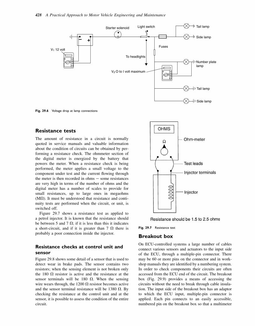
Resistance tests
The amount of resistance in a circuit is normallyquoted in service manuals and valuable informationabout the condition of circuits can be obtained by per-forming a resistance check. The ohmmeter section ofthe digital meter is energized by the battery thatpowers the meter. When a resistance check is beingperformed, the meter applies a small voltage to thecomponent under test and the current flowing throughthe meter is then recorded in ohms e some resistancesare very high in terms of the number of ohms and thedigital meter has a number of scales to provide forsmall resistances, up to large ones in megaohms(MV). It must be understood that resistance and conti-nuity tests are performed when the circuit, or unit, isswitched off.
Figure 29.7 shows a resistance test as applied toa petrol injector. It is known that the resistance shouldbe between 5 and 7 V; if it is less than this it indicatesa short-circuit, and if it is greater than 7 V there isprobably a poor connection inside the injector.
Resistance checks at control unit andsensor
Figure 29.8 shows some detail of a sensor that is used todetect wear in brake pads. The sensor contains tworesistors; when the sensing element is not broken onlythe 180 V resistor is active and the resistance at thesensor terminals will be 180 V. When the sensingwire wears through, the 1200 V resistor becomes activeand the sensor terminal resistance will be 1380 V. Bychecking the resistance at the control unit and at thesensor, it is possible to assess the condition of the entirecircuit.
Breakout box
On ECU-controlled systems a large number of cablesconnect various sensors and actuators to the input sideof the ECU, through a multiple-pin connector. Theremay be 60 or more pins on the connector and in work-shop manuals they are identified by a numbering system.In order to check components their circuits are oftenaccessed from the ECU end of the circuit. The breakoutbox (Fig. 29.9) provides a means of accessing thecircuits without the need to break through cable insula-tion. The input side of the breakout box has an adaptorto which the ECU input, multiple-pin connector isapplied. Each pin connects to an easily accessible,numbered pin on the breakout box so that a multimeter
Fig. 29.7 Resistance test
+–
V1 12 volt
Starter solenoid Light switch
Tail lamp
Tail lamp
Side lamp
Side lamp
Number platelamp
Fuses
To headlights
V2 O to I volt maximum
Fig. 29.6 Voltage drop at lamp connections
428 A Practical Approach to Motor Vehicle Engineering and Maintenance
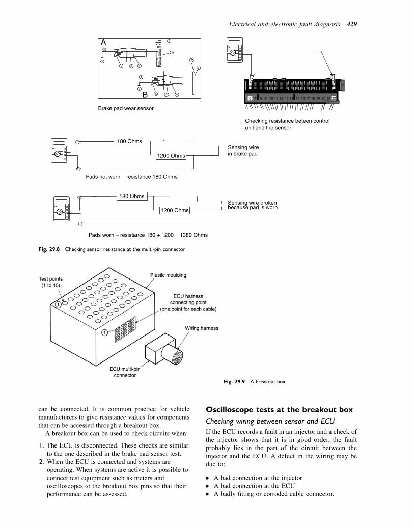
can be connected. It is common practice for vehiclemanufacturers to give resistance values for componentsthat can be accessed through a breakout box.
A breakout box can be used to check circuits when:
1. The ECU is disconnected. These checks are similarto the one described in the brake pad sensor test.
2. When the ECU is connected and systems areoperating. When systems are active it is possible toconnect test equipment such as meters andoscilloscopes to the breakout box pins so that theirperformance can be assessed.
Oscilloscope tests at the breakout box
Checking wiring between sensor and ECU
If the ECU records a fault in an injector and a check ofthe injector shows that it is in good order, the faultprobably lies in the part of the circuit between theinjector and the ECU. A defect in the wiring may bedue to:
� A bad connection at the injector� A bad connection at the ECU� A badly fitting or corroded cable connector.
Fig. 29.9 A breakout box
6 7 8 9 10 11 12 13 14 15 16 17 18 19 20 21 22
180 Ohms
1200 Ohms
Pads not worn – resistance 180 Ohms
Sensing wire broken
Sensing wirein brake pad
because pad is worn
Pads worn – resistance 180 + 1200 = 1380 Ohms
6 5 4
7
13
2A
180 Ohms
1200 Ohms
1
2
3
7
6 5 4B
Brake pad wear sensor
Checking resistance beteen controlunit and the sensor
Fig. 29.8 Checking sensor resistance at the multi-pin connector
Electrical and electronic fault diagnosis 429
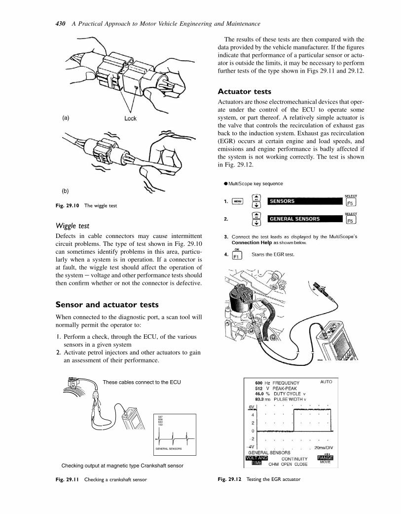
Wiggle test
Defects in cable connectors may cause intermittentcircuit problems. The type of test shown in Fig. 29.10can sometimes identify problems in this area, particu-larly when a system is in operation. If a connector isat fault, the wiggle test should affect the operation ofthe systeme voltage and other performance tests shouldthen confirm whether or not the connector is defective.
Sensor and actuator tests
When connected to the diagnostic port, a scan tool willnormally permit the operator to:
1. Perform a check, through the ECU, of the varioussensors in a given system
2. Activate petrol injectors and other actuators to gainan assessment of their performance.
The results of these tests are then compared with thedata provided by the vehicle manufacturer. If the figuresindicate that performance of a particular sensor or actu-ator is outside the limits, it may be necessary to performfurther tests of the type shown in Figs 29.11 and 29.12.
Actuator tests
Actuators are those electromechanical devices that oper-ate under the control of the ECU to operate somesystem, or part thereof. A relatively simple actuator isthe valve that controls the recirculation of exhaust gasback to the induction system. Exhaust gas recirculation(EGR) occurs at certain engine and load speeds, andemissions and engine performance is badly affected ifthe system is not working correctly. The test is shownin Fig. 29.12.
These cables connect to the ECU
Checking output at magnetic type Crankshaft sensor
597856
150840
GENERAL SENSORS
Fig. 29.11 Checking a crankshaft sensor Fig. 29.12 Testing the EGR actuator
Fig. 29.10 The wiggle test
430 A Practical Approach to Motor Vehicle Engineering and Maintenance
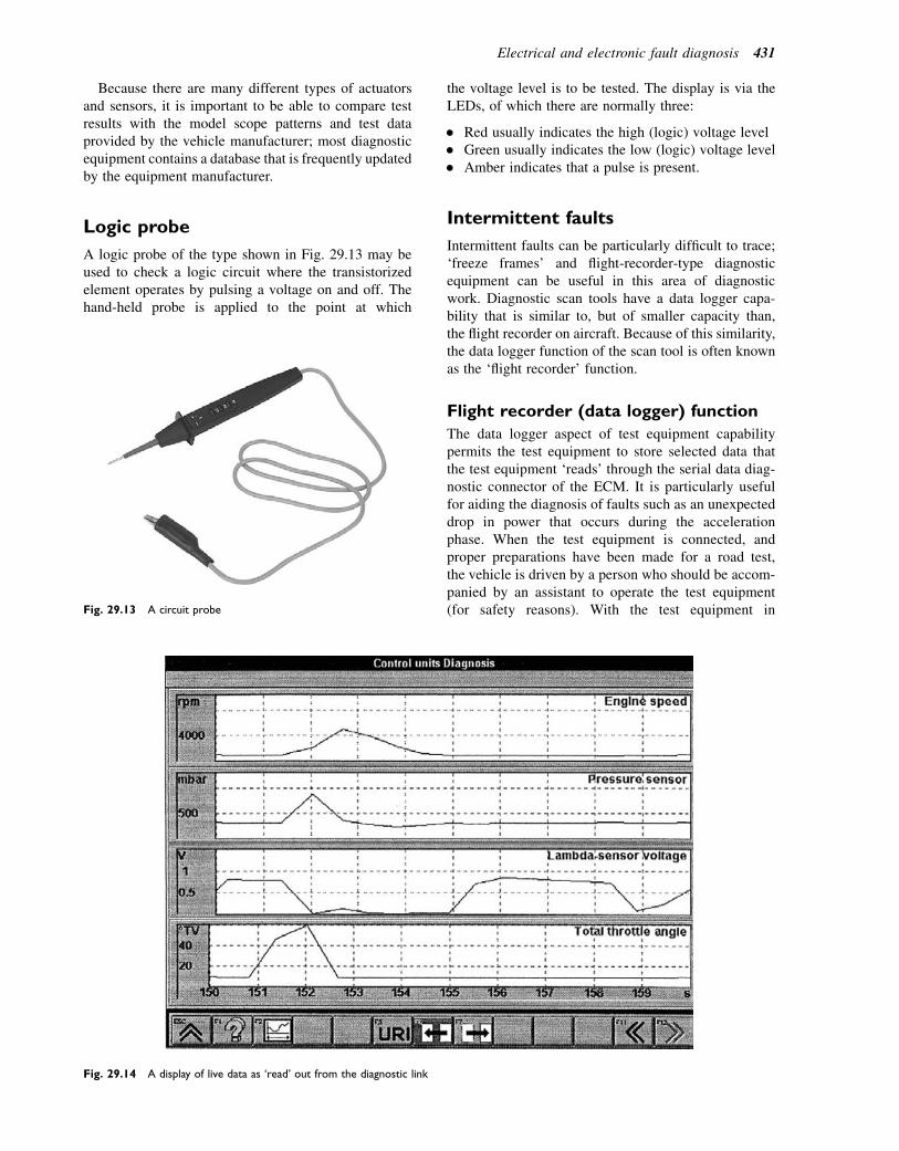
Because there are many different types of actuatorsand sensors, it is important to be able to compare testresults with the model scope patterns and test dataprovided by the vehicle manufacturer; most diagnosticequipment contains a database that is frequently updatedby the equipment manufacturer.
Logic probe
A logic probe of the type shown in Fig. 29.13 may beused to check a logic circuit where the transistorizedelement operates by pulsing a voltage on and off. Thehand-held probe is applied to the point at which
the voltage level is to be tested. The display is via theLEDs, of which there are normally three:
� Red usually indicates the high (logic) voltage level� Green usually indicates the low (logic) voltage level� Amber indicates that a pulse is present.
Intermittent faults
Intermittent faults can be particularly difficult to trace;‘freeze frames’ and flight-recorder-type diagnosticequipment can be useful in this area of diagnosticwork. Diagnostic scan tools have a data logger capa-bility that is similar to, but of smaller capacity than,the flight recorder on aircraft. Because of this similarity,the data logger function of the scan tool is often knownas the ‘flight recorder’ function.
Flight recorder (data logger) function
The data logger aspect of test equipment capabilitypermits the test equipment to store selected data thatthe test equipment ‘reads’ through the serial data diag-nostic connector of the ECM. It is particularly usefulfor aiding the diagnosis of faults such as an unexpecteddrop in power that occurs during the accelerationphase. When the test equipment is connected, andproper preparations have been made for a road test,the vehicle is driven by a person who should be accom-panied by an assistant to operate the test equipment(for safety reasons). With the test equipment inFig. 29.13 A circuit probe
Fig. 29.14 A display of live data as ‘read’ out from the diagnostic link
Electrical and electronic fault diagnosis 431
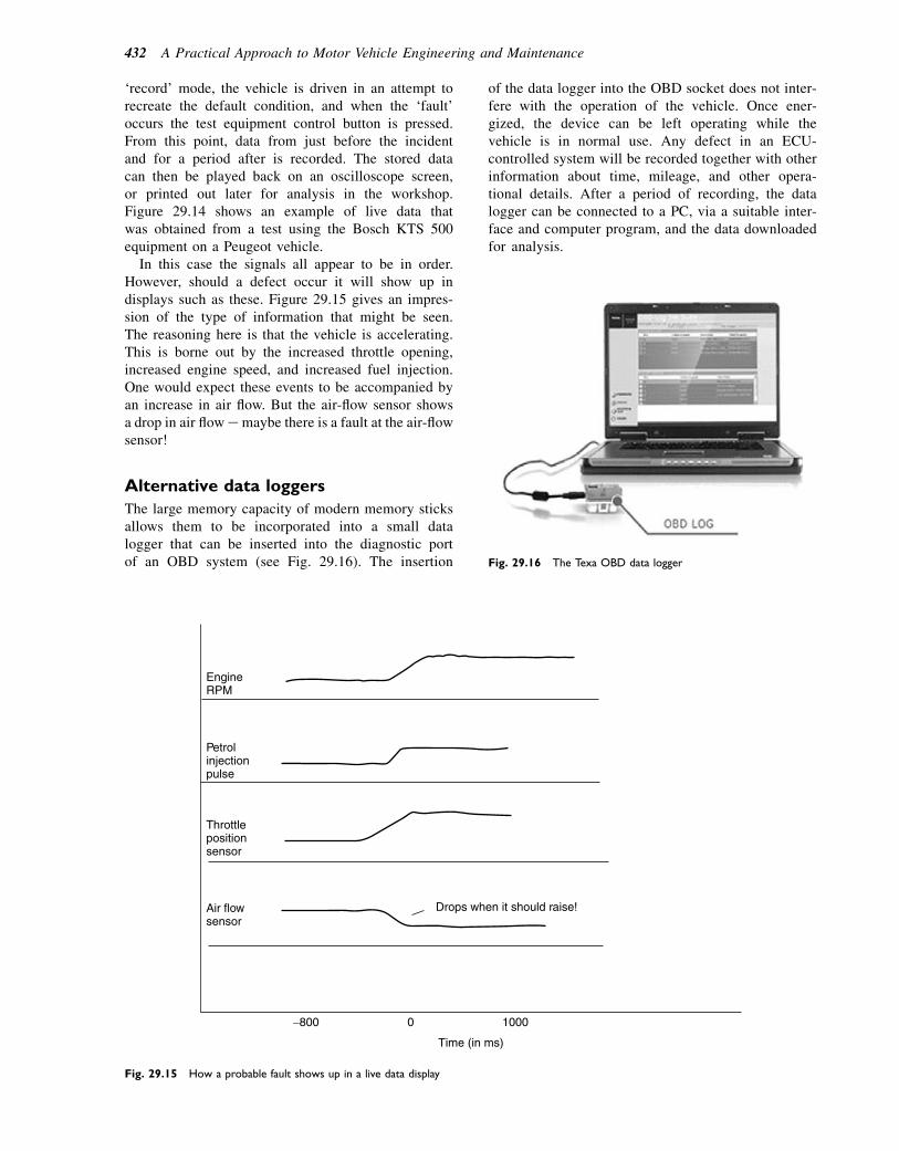
‘record’ mode, the vehicle is driven in an attempt torecreate the default condition, and when the ‘fault’occurs the test equipment control button is pressed.From this point, data from just before the incidentand for a period after is recorded. The stored datacan then be played back on an oscilloscope screen,or printed out later for analysis in the workshop.Figure 29.14 shows an example of live data thatwas obtained from a test using the Bosch KTS 500equipment on a Peugeot vehicle.
In this case the signals all appear to be in order.However, should a defect occur it will show up indisplays such as these. Figure 29.15 gives an impres-sion of the type of information that might be seen.The reasoning here is that the vehicle is accelerating.This is borne out by the increased throttle opening,increased engine speed, and increased fuel injection.One would expect these events to be accompanied byan increase in air flow. But the air-flow sensor showsa drop in air flowemaybe there is a fault at the air-flowsensor!
Alternative data loggers
The large memory capacity of modern memory sticksallows them to be incorporated into a small datalogger that can be inserted into the diagnostic portof an OBD system (see Fig. 29.16). The insertion
of the data logger into the OBD socket does not inter-fere with the operation of the vehicle. Once ener-gized, the device can be left operating while thevehicle is in normal use. Any defect in an ECU-controlled system will be recorded together with otherinformation about time, mileage, and other opera-tional details. After a period of recording, the datalogger can be connected to a PC, via a suitable inter-face and computer program, and the data downloadedfor analysis.
Drops when it should raise!Air flowsensor
Throttlepositionsensor
Petrolinjectionpulse
EngineRPM
−800 0 1000
Time (in ms)
Fig. 29.15 How a probable fault shows up in a live data display
Fig. 29.16 The Texa OBD data logger
432 A Practical Approach to Motor Vehicle Engineering and Maintenance
Self-assessment questions1. Diagnostic trouble codes are:
(a) computer codes that can be displayed at a faultcode reader
(b) only readable through the serial connector ofthe ECM
(c) generated at random whenever there is a faulton any part of the vehicle
(d) information that tells the user exactly what thefault is.
2. A limited operating strategy:(a) permits the vehicle to be driven until a repair
can be made(b) cuts out fuel injection above a certain engine
speed(c) retards igntion timing to stop combustion
knock(d) refers to the limited nature of fault codes for
diagnostic purposes.3. Microprocessor-based diagnostic testers can:
(a) only read fault codes(b) read fault codes and perform actuator tests via
the serial port of the vehicle(c) reset the values stored in a mask programmable
ROM(d) only read out diagnostic data from CAN
systems.4. The standardized serial port for diagnostics that is
used with OBD2 has:(a) a three-pin connector(b) no specified number of pins but its position on
the vehicle is specified(c) a 16-pin connector(d) no pins specifically allocated to the OBD2
emissions systems.5. In order to read out diagnostic trouble codes (fault
codes) it is necessary to:(a) earth the K-line and read the flashing
light(b) carry out the manufacturer’s recommended
procedure(c) have the engine running(d) take the vehicle for a road test first.
6. An ABS ECM should have good self-diagnosticsbecause:(a) the sensor output signals cannot be measured
independently(b) it is difficult to simulate actual anti-lock
conditions with a stationary vehicle(c) if the ABS warning light comes on it will stop the
vehicle(d) the fault codes are always stored in an EEPROM.
7. A ‘freeze frame’ is:(a) a set of ROM data that is used in very cold
weather(b) data that is used by the ECM when there is an
emergency(c) a set of data about operating conditions that is
placed in the fault code memory when the self-diagnostics detects a fault
(d) a diagnostic feature of very early types ofelectronic control only.
8. In standardized fault codes:(a) digit 1, at the left-hand end, identifies the vehicle
system(b) the digit at the far right-hand end identifies the
system(c) all computer-controlled vehicle systems must
use them(d) the identifying digits can appear in any order.
9. Pulse width modulation (PWM) is a system thatuses pulses of electric current to operate actuators.Make a list of ECU-controlled actuators that usethis method of operation. How is the duty cyclemeasurement related to PWM?
10. Why is it that diagnostic fault codes are not alwaysthe complete answer to tracing a fault in an OBDsystem?
11. Make a list of the diagnostic equipment in yourworkshop. Describe the opportunities that areavailable for you to keep abreast of developments invehicle technology.
12. Describe any electronics-related diagnosticproblem that you have experienced. What do youthink that you learned from the experience? Howmuch do think that underpinning knowledge ofvehicle systems helped you and your colleagues inmaking a successful diagnosis?
Electrical and electronic fault diagnosis 433

30Nuts, bolts, and spanners
Topics covered in thischapter
The origin of standards in sizes and thread formsLock nutsSpanner sizesThread restoration
Dimensions of nuts, bolts, andspanners
In the early 1800s, Joseph Whitworth devised a set ofstandards for screw threads and their associated nutsand bolts. Under the Whitworth system the size of thebolt head and nut is determined by the diameter of thethreaded part of the bolt. For engineering drawingpurposes, the distance across the flats of the bolt head(S) was set at:
S 5 1:25D 11
8inch;
where D 5 diameter of the threaded part of the bolt.The size of the spanner required for these nuts and
bolts is marked on the spanner, near the jaws (seeFig. 30.2). A spanner for a half-inch Whitworth bolthas a distance across the jaws of 0.75 inch.
A similar system that is used in modern automobilework makes use of metric dimensions. In this case thesize marked on the spanner is the distance across theflats of the nut as shown in Fig. 30.1. Table 30.1 showsthe relation between thread diameter and spanner size.
Screw threads
The pitch of a screw thread is the distance between cor-responding points on a thread, as measured form peak topeak. The angle of the thread is determined by the typeof thread that is being used (see Fig. 30.3). A number ofdifferent thread types may be found in automobile prac-tice and it is useful to have a thread gauge to hand when-ever there is a question about the exact type of threadthat is in use (see Fig. 30.4).
Studs
Studs are used in many applications, such as that shownin Fig. 30.5. The threaded part that screws into the maincomponent is normally shorter than the thread at theother end of the stud; this is an important point to notebecause damage may be caused if a stud is fitted thewrong way round. Special tools called stud removersare required for removing and fitting studs.
Thread length
Nominal length
Bolt diameter
Size across flats
Fig. 30.1 Dimensions of a bolt
� 2011 Allan Bonnick and Derek Newbold. Published by Elsevier Ltd. All rights reserved
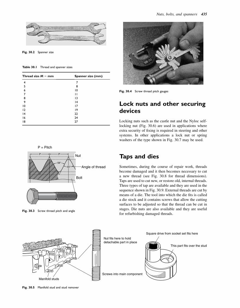
Lock nuts and other securingdevices
Locking nuts such as the castle nut and the Nyloc self-locking nut (Fig. 30.6) are used in applications whereextra security of fixing is required in steering and othersystems. In other applications a lock nut or springwashers of the type shown in Fig. 30.7 may be used.
Taps and dies
Sometimes, during the course of repair work, threadsbecome damaged and it then becomes necessary to cuta new thread (see Fig. 30.8 for thread dimensions).Taps are used to cut new, or restore old, internal threads.Three types of tap are available and they are used in thesequence shown in Fig. 30.9. External threads are cut bymeans of a die. The tool into which the die fits is calleda die stock and it contains screws that allow the cuttingsurfaces to be adjusted so that the thread can be cut instages. Die nuts are also available and they are usefulfor refurbishing damaged threads.
Fig. 30.2 Spanner size
P = Pitch
Nut
Angle of thread
Bolt
P P
58°
55°
Fig. 30.3 Screw thread pitch and angle
Table 30.1 Thread and spanner sizes
Thread size M 5 mm Spanner size (mm)
4 7
5 8
6 10
7 11
8 13
9 14
10 17
12 19
14 22
16 24
18 27
Fig. 30.4 Screw thread pitch gauges
Manifold studs
Screws into main component
Nut fits here to holddetachable part in place
Square drive from socket set fits here
This part fits over the stud
Fig. 30.5 Manifold stud and stud remover
Nuts, bolts, and spanners 435
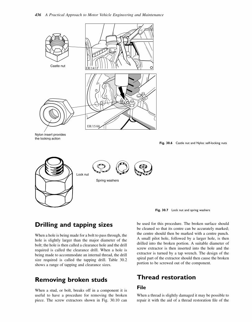
Drilling and tapping sizes
When a hole is being made for a bolt to pass through, thehole is slightly larger than the major diameter of thebolt; the hole is then called a clearance hole and the drillrequired is called the clearance drill. When a hole isbeing made to accommodate an internal thread, the drillsize required is called the tapping drill. Table 30.2shows a range of tapping and clearance sizes.
Removing broken studs
When a stud, or bolt, breaks off in a component it isuseful to have a procedure for removing the brokenpiece. The screw extractors shown in Fig. 30.10 can
be used for this procedure. The broken surface shouldbe cleaned so that its centre can be accurately marked;the centre should then be marked with a centre punch.A small pilot hole, followed by a larger hole, is thendrilled into the broken portion. A suitable diameter ofscrew extractor is then inserted into the hole and theextractor is turned by a tap wrench. The design of thespiral part of the extractor should then cause the brokenportion to be screwed out of the component.
Thread restoration
File
When a thread is slightly damaged it may be possible torepair it with the aid of a thread restoration file of the
Castle nut
Nylon insert providesthe locking action
ER/15/68
ER/14/11
Fig. 30.6 Castle nut and Nyloc self-locking nuts
Lock nut
Spring washers
Fig. 30.7 Lock nut and spring washers
436 A Practical Approach to Motor Vehicle Engineering and Maintenance
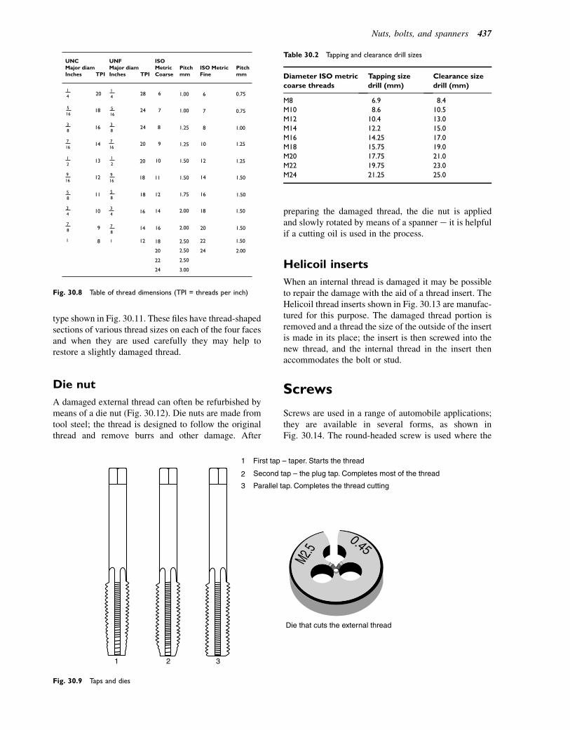
type shown in Fig. 30.11. These files have thread-shapedsections of various thread sizes on each of the four facesand when they are used carefully they may help torestore a slightly damaged thread.
Die nut
A damaged external thread can often be refurbished bymeans of a die nut (Fig. 30.12). Die nuts are made fromtool steel; the thread is designed to follow the originalthread and remove burrs and other damage. After
preparing the damaged thread, the die nut is appliedand slowly rotated by means of a spanner e it is helpfulif a cutting oil is used in the process.
Helicoil inserts
When an internal thread is damaged it may be possibleto repair the damage with the aid of a thread insert. TheHelicoil thread inserts shown in Fig. 30.13 are manufac-tured for this purpose. The damaged thread portion isremoved and a thread the size of the outside of the insertis made in its place; the insert is then screwed into thenew thread, and the internal thread in the insert thenaccommodates the bolt or stud.
Screws
Screws are used in a range of automobile applications;they are available in several forms, as shown inFig. 30.14. The round-headed screw is used where the
TPI TPI
UNCMajor diamInches
UNFMajor diamInches
ISOMetricCoarse
Pitchmm
Pitchmm
ISO MetricFine
8
9
10
11
12
12
13
14
14
16
16
18
18
18
20
20
20
28 1.00
1.00
1.001.25
1.251.25
1.251.50
1.50
1.50
1.50
1.50
1.50
1.50
1.75
2.00
2.00
2.002.50
2.50
3.00
2.50
24
24
6 0.75
0.757
8
9
10
11
12
14
6
7
8
10
12
14
16
18
16
18
20
20
22
22
24
24
14
12
12
916
916
58
58
34
34
78
1 1
78
516
14
516
716
38
716
38
Fig. 30.8 Table of thread dimensions (TPI = threads per inch)M2.5
0.45
1 First tap – taper. Starts the thread
Second tap – the plug tap. Completes most of the thread
Parallel tap. Completes the thread cutting
Die that cuts the external thread
2
3
1 2 3
Fig. 30.9 Taps and dies
Table 30.2 Tapping and clearance drill sizes
Diameter ISO metric
coarse threads
Tapping size
drill (mm)
Clearance size
drill (mm)
M8 6.9 8.4
M10 8.6 10.5
M12 10.4 13.0
M14 12.2 15.0
M16 14.25 17.0
M18 15.75 19.0
M20 17.75 21.0
M22 19.75 23.0
M24 21.25 25.0
Nuts, bolts, and spanners 437
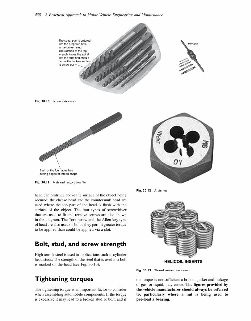
head can protrude above the surface of the object beingsecured; the cheese head and the countersunk head areused where the top part of the head is flush with thesurface of the object. The four types of screwdriverthat are used to fit and remove screws are also shownin the diagram. The Torx screw and the Allen key typeof head are also used on bolts; they permit greater torqueto be applied than could be applied via a slot.
Bolt, stud, and screw strength
High tensile steel is used in applications such as cylinderhead studs. The strength of the steel that is used in a boltis marked on the head (see Fig. 30.15).
Tightening torques
The tightening torque is an important factor to considerwhen assembling automobile components. If the torqueis excessive it may lead to a broken stud or bolt, and if
the torque is not sufficient a broken gasket and leakageof gas, or liquid, may ensue. The figures provided bythe vehicle manufacturer should always be referredto, particularly where a nut is being used topre-load a bearing.
The spiral part is enteredinto the prepared holein the broken stud.The rotation of the tapwrench forces the spiralinto the stud and shouldcause the broken sectionto screw out
Wrench
Fig. 30.10 Screw extractors
Each of the four faces hascutting edges of thread shape
Fig. 30.11 A thread restoration file
Fig. 30.12 A die nut
Fig. 30.13 Thread restoration inserts
438 A Practical Approach to Motor Vehicle Engineering and Maintenance
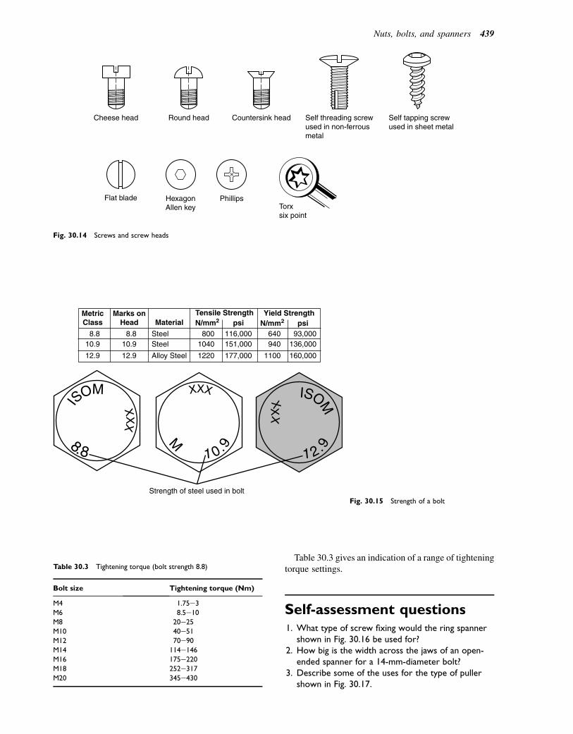
Table 30.3 gives an indication of a range of tighteningtorque settings.
Self-assessment questions1. What type of screw fixing would the ring spanner
shown in Fig. 30.16 be used for?2. How big is the width across the jaws of an open-
ended spanner for a 14-mm-diameter bolt?3. Describe some of the uses for the type of puller
shown in Fig. 30.17.
Cheese head Round head Countersink head Self threading screwused in non-ferrousmetal
Self tapping screwused in sheet metal
Flat blade HexagonAllen key
PhillipsTorxsix point
Fig. 30.14 Screws and screw heads
XX
X
ISOM
8.8 1 0.9
XXX
ISOM
1 2.9
XXXM
Strength of steel used in bolt
MetricClass
Marks onHead Material
Tensile Strengthpsi
Yield Strength
SteelSteel
Alloy Steel
640940
1100
93,000136,000
160,000
8001040
1220
116,000151,000
177,000
8.810.9
12.9
8.810.9
12.9
N/mm2psiN/mm2
Fig. 30.15 Strength of a bolt
Table 30.3 Tightening torque (bolt strength 8.8)
Bolt size Tightening torque (Nm)
M4 1.75e3
M6 8.5e10
M8 20e25
M10 40e51M12 70e90
M14 114e146
M16 175e220M18 252e317
M20 345e430
Nuts, bolts, and spanners 439
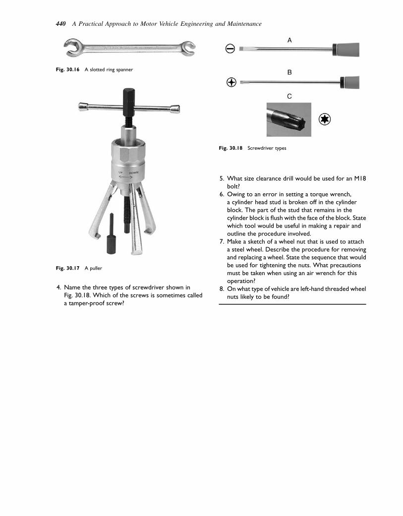
4. Name the three types of screwdriver shown inFig. 30.18. Which of the screws is sometimes calleda tamper-proof screw?
5. What size clearance drill would be used for an M18bolt?
6. Owing to an error in setting a torque wrench,a cylinder head stud is broken off in the cylinderblock. The part of the stud that remains in thecylinder block is flush with the face of the block. Statewhich tool would be useful in making a repair andoutline the procedure involved.
7. Make a sketch of a wheel nut that is used to attacha steel wheel. Describe the procedure for removingand replacing a wheel. State the sequence that wouldbe used for tightening the nuts. What precautionsmust be taken when using an air wrench for thisoperation?
8. On what type of vehicle are left-hand threaded wheelnuts likely to be found?
Fig. 30.17 A puller
Fig. 30.18 Screwdriver types
Fig. 30.16 A slotted ring spanner
440 A Practical Approach to Motor Vehicle Engineering and Maintenance

31Measuring instruments andmeasurement
Topics covered in thischapter
MicrometersVernier calipersFeeler gaugesNumber approximations e typical motor vehiclemeasurementsElectrical test meters
Accurate measurement plays an important part in vehi-cle maintenance and repair. For example, measurementsthat are routinely taken are:
� valve clearances� steering angles and track alignment� exhaust emissions� compression pressures� alternator charging rate� tyre pressures� brake disc ‘run-out’� brake disc thickness, brake pad thickness� shaft and bearing clearances.
Figure 31.1 shows a number of examples of the typesof measurements and the measuring instruments that areused in motor vehicle maintenance and repair work.
Measuring instruments
Feeler gauges
Feeler gauges are used in motor vehicle repair and main-tenance for such purposes as checking valve clearances,piston ring gaps, and many other clearances. The feelergauges, shown in Fig. 31.2, are typical of the type thatform a part of a technician’s tool kit. They are madefrom high-grade steel that is tempered for hard wearand durability and the size of each blade is etched intothe surface.
Figure 31.1(a) shows a feeler gauge in use, measuringvalve clearance. In this example, the feeler gauge isbeing inserted between the heel of the cam and thecam follower, with the valve in the fully closed position.When ready to proceed with the measurement, thegauges of the required thickness are inserted in theclearance between the heel of the cam and the camfollower, and a light-hand force, sufficient to slide thefeeler gauge through the gap, is applied.
Non-magnetic feeler gauges
Feeler gauges made from brass or some other non-magnetic material, such as a suitable plastic, are usedto check the air gap on some types of electronic ignitiondistributors.
Vernier calipers
Figure 31.1(b) shows the depth gauge section ofa vernier caliper being used to check the drive trainend-float in a final drive assembly. In this applicationthe vernier gauge is being used in conjunction with anengineer’s straight edge. Figure 31.3 shows a verniergauge in greater detail. This instrument measures toan accuracy of 0.02 mm, which is quite adequate formost vehicle repair and maintenance work. As indicatedin the diagram, the instrument is versatile as it may beused for internal, external, and depth measurements.The instrument should be treated carefully and kept inclean, dry conditions when not in use.
Reading a vernier scale
For the following explanation please refer to the metricreading at the bottom of Fig. 31.3.
The main scale is graduated in millimetres and arenumbered at every 10 divisions. The vernier scale isdivided into 50 divisions over a distance of 49 mmand each division is equal to 49/50ths of a mm e thatis, 0.98 mm. The difference between the divisions onthe two scales is 1.00 2 0.98 5 0.02 mm.
� 2011 Allan Bonnick and Derek Newbold. Published by Elsevier Ltd. All rights reserved
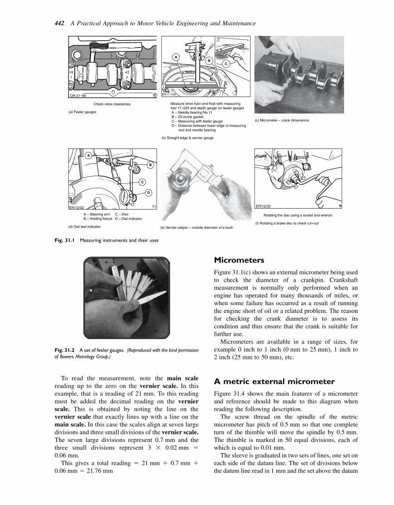
To read the measurement, note the main scalereading up to the zero on the vernier scale. In thisexample, that is a reading of 21 mm. To this readingmust be added the decimal reading on the vernierscale. This is obtained by noting the line on thevernier scale that exactly lines up with a line on themain scale. In this case the scales align at seven largedivisions and three small divisions of the vernier scale.The seven large divisions represent 0.7 mm and thethree small divisions represent 3 3 0.02 mm 50.06 mm.
This gives a total reading 5 21 mm 1 0.7 mm 10.06 mm 5 21.76 mm
Micrometers
Figure 31.1(c) shows an external micrometer being usedto check the diameter of a crankpin. Crankshaftmeasurement is normally only performed when anengine has operated for many thousands of miles, orwhen some failure has occurred as a result of runningthe engine short of oil or a related problem. The reasonfor checking the crank diameter is to assess itscondition and thus ensure that the crank is suitable forfurther use.
Micrometers are available in a range of sizes, forexample 0 inch to 1 inch (0 mm to 25 mm), 1 inch to2 inch (25 mm to 50 mm), etc.
A metric external micrometer
Figure 31.4 shows the main features of a micrometerand reference should be made to this diagram whenreading the following description.
The screw thread on the spindle of the metricmicrometer has pitch of 0.5 mm so that one completeturn of the thimble will move the spindle by 0.5 mm.The thimble is marked in 50 equal divisions, each ofwhich is equal to 0.01 mm.
The sleeve is graduated in two sets of lines, one set oneach side of the datum line. The set of divisions belowthe datum line read in 1 mm and the set above the datum
Fig. 31.2 A set of feeler gauges. (Reproduced with the kind permission
of Bowers Metrology Group.)
(a) Feeler gauges
Check valve clearances. Measure drive train end float with measuringtool 17–025 and depth gauge (or feeler gauge) A – Needle bearing No.11 B – Oil pump gasket C – Measuring with feeler gauge D – Distance between lower edge of measuring tool and needle bearing
(b) Straight edge & vernier gauge
ER/12/32
A – Steering arm B – Holding fixture
C – Disc D – Dial indicator
A
C
D
B
(d) Dial test indicator
T1 ER/12/33
Rotating the disc using a socket and wrench.
(f) Rotating a brake disc to check run-out (e) Vernier caliper – outside diameter of a bush
Fig. 31.1 Measuring instruments and their uses
442 A Practical Approach to Motor Vehicle Engineering and Maintenance
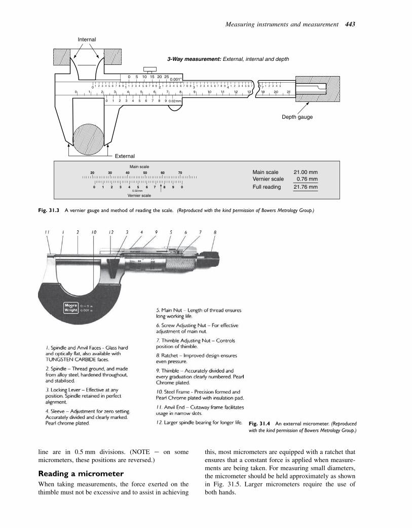
line are in 0.5 mm divisions. (NOTE e on somemicrometers, these positions are reversed.)
Reading a micrometer
When taking measurements, the force exerted on thethimble must not be excessive and to assist in achieving
this, most micrometers are equipped with a ratchet thatensures that a constant force is applied when measure-ments are being taken. For measuring small diameters,the micrometer should be held approximately as shownin Fig. 31.5. Larger micrometers require the use ofboth hands.
0 5 10 15 20 25 0.001"
Main scale
Vernier scale
Main scale Vernier scale
Full reading
21.00 mm0.76 mm
21.76 mm
Internal
Depth gauge
3-Way measurement: External, internal and depth
External
Fig. 31.3 A vernier gauge and method of reading the scale. (Reproduced with the kind permission of Bowers Metrology Group.)
Fig. 31.4 An external micrometer. (Reproduced
with the kind permission of Bowers Metrology Group.)
Measuring instruments and measurement 443
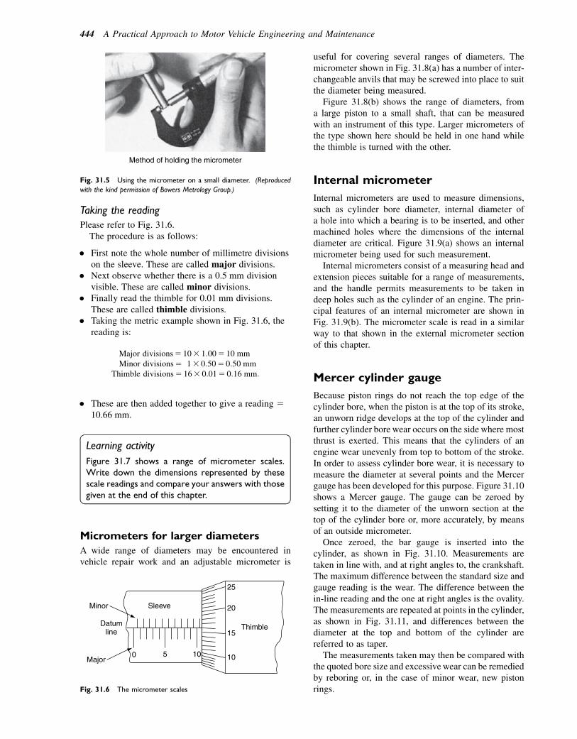
Taking the reading
Please refer to Fig. 31.6.The procedure is as follows:
� First note the whole number of millimetre divisionson the sleeve. These are called major divisions.
� Next observe whether there is a 0.5 mm divisionvisible. These are called minor divisions.
� Finally read the thimble for 0.01 mm divisions.These are called thimble divisions.
� Taking the metric example shown in Fig. 31.6, thereading is:
Major divisions5 103 1:005 10 mmMinor divisions5 13 0:505 0:50 mm
Thimble divisions5 163 0:015 0:16 mm:
� These are then added together to give a reading 510.66 mm.
Learning activity
Figure 31.7 shows a range of micrometer scales.Write down the dimensions represented by thesescale readings and compare your answers with thosegiven at the end of this chapter.
Micrometers for larger diameters
A wide range of diameters may be encountered invehicle repair work and an adjustable micrometer is
useful for covering several ranges of diameters. Themicrometer shown in Fig. 31.8(a) has a number of inter-changeable anvils that may be screwed into place to suitthe diameter being measured.
Figure 31.8(b) shows the range of diameters, froma large piston to a small shaft, that can be measuredwith an instrument of this type. Larger micrometers ofthe type shown here should be held in one hand whilethe thimble is turned with the other.
Internal micrometer
Internal micrometers are used to measure dimensions,such as cylinder bore diameter, internal diameter ofa hole into which a bearing is to be inserted, and othermachined holes where the dimensions of the internaldiameter are critical. Figure 31.9(a) shows an internalmicrometer being used for such measurement.
Internal micrometers consist of a measuring head andextension pieces suitable for a range of measurements,and the handle permits measurements to be taken indeep holes such as the cylinder of an engine. The prin-cipal features of an internal micrometer are shown inFig. 31.9(b). The micrometer scale is read in a similarway to that shown in the external micrometer sectionof this chapter.
Mercer cylinder gauge
Because piston rings do not reach the top edge of thecylinder bore, when the piston is at the top of its stroke,an unworn ridge develops at the top of the cylinder andfurther cylinder bore wear occurs on the side where mostthrust is exerted. This means that the cylinders of anengine wear unevenly from top to bottom of the stroke.In order to assess cylinder bore wear, it is necessary tomeasure the diameter at several points and the Mercergauge has been developed for this purpose. Figure 31.10shows a Mercer gauge. The gauge can be zeroed bysetting it to the diameter of the unworn section at thetop of the cylinder bore or, more accurately, by meansof an outside micrometer.
Once zeroed, the bar gauge is inserted into thecylinder, as shown in Fig. 31.10. Measurements aretaken in line with, and at right angles to, the crankshaft.The maximum difference between the standard size andgauge reading is the wear. The difference between thein-line reading and the one at right angles is the ovality.The measurements are repeated at points in the cylinder,as shown in Fig. 31.11, and differences between thediameter at the top and bottom of the cylinder arereferred to as taper.
The measurements taken may then be compared withthe quoted bore size and excessive wear can be remediedby reboring or, in the case of minor wear, new pistonrings.
Method of holding the micrometer
Fig. 31.5 Using the micrometer on a small diameter. (Reproduced
with the kind permission of Bowers Metrology Group.)
Datumline
Sleeve
Thimble
1010
20
15
25
50
Minor
Major
Fig. 31.6 The micrometer scales
444 A Practical Approach to Motor Vehicle Engineering and Maintenance

Typical applications
(b)
Anvillocknut
Anviladjusting
nuts
Anvil
Frame Anvil peg
Sectionalview
Standards Keys
Interchangeable anvils
50%
25%
75%
(a)
0-100%
Fig. 31.8 Exercises on reading micrometer scales
Datumline
Sleeve
55
1010
15
Thimble
(a)
Datumline
Sleeve
1510
2015
20
Thimble
(b)
Micrometer size 0–25 mm
Micrometer size 25–50 mm
Datumline
Sleeve
100
155
10
Thimble
(c)
Datumline
Sleeve
0
25
530
35
Thimble
(d)
Micrometer size 75–100 mm
Micrometer size 0–25 mm
Fig. 31.7 An adjustable micrometer and its uses. (Reproduced with the kind permission of Bowers Metrology Group.)
Measuring instruments and measurement 445
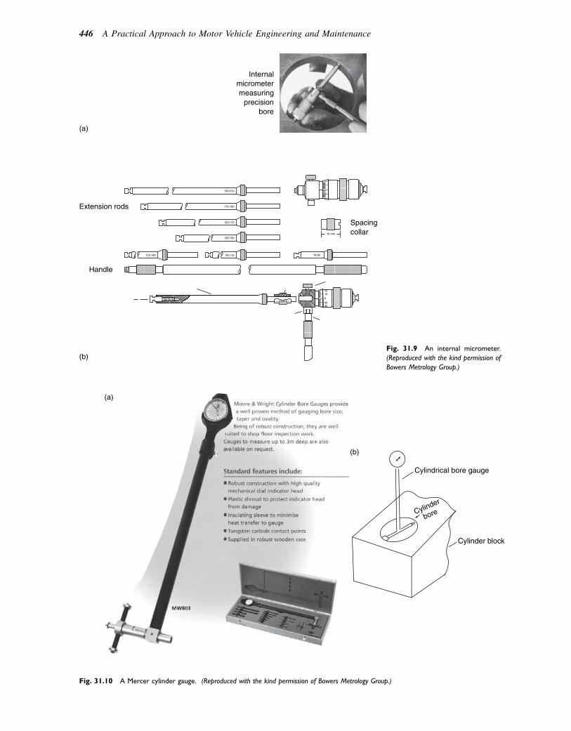
Extension rods
(a)
(b)
Handle
Spacing collar
Internal micrometer measuring
precision bore
Fig. 31.9 An internal micrometer.
(Reproduced with the kind permission of
Bowers Metrology Group.)
(a)
Cylindrical bore gauge
Cylinder block
Cylinder
bore
(b)
Fig. 31.10 A Mercer cylinder gauge. (Reproduced with the kind permission of Bowers Metrology Group.)
446 A Practical Approach to Motor Vehicle Engineering and Maintenance

Calipers, inside and out
Figure 31.11 show internal and external calipers beingset against a steel rule prior to making measurementsof inside and outside diameters. These types of measure-ments may be found useful in assembly work, such asfitting new parts where it may be necessary to checkone diameter against another.
Dial test indicators
Dial test indicators (DTIs) of the type shown inFig. 31.12 are used for measurements, such as check-ing run-out on brake discs and checking end float ona crankshaft.
There are many other instances where a DTI would beused, but the following two examples will suffice toexplain the principles involved.
Brake disc run-out
Figure 31.1(d) shows a dial test indicator that has beenset up to test the axial run-out that occurs when thedisc is rotated, as shown in Fig. 31.1(f). This measure-ment is important because of the effect that excessiverun-out may have on the operation of the brakes.Among the brake problems that may be caused aredefects, such as excessive pad wear and low brakeefficiency.
Excessive disc run-out may be caused by a distorteddisc, dirt between the disc and the flange that it is fittedto, or other problems in the wheel hub. Run-out shouldnot exceed 0.15 mm (0.006 in) when measured in a posi-tion near the edge of the disc, but clear of any corrosionthat may exist on the edge of the disc.
Crankshaft end float
End thrust on the crankshaft occurs when the clutch isoperated and from the weight of the crankshaft whenthe vehicle is operating on an incline. The end thrustis normally taken by thrust bearings that are fitted tothe centre main bearing of the crankshaft, as shown inFig. 31.13.
There must be sufficient clearance between themachined faces on the crankshaft and the thrust facesof the thrust bearing to permit proper lubrication andallow for thermal expansion. If the clearance is toogreat, lubrication may fail because of loss of oil pres-sure; if the clearance is too small, seizure may occur.The clearance is checked by means of a DTI thatmeasures the end float on the crankshaft, as shown inFig. 31.14. A lever, suitably positioned, is used tomove the crankshaft to and fro in order to check theend float.
Setting inside caliper
N.B. Use of tegsquare together with rule providing an abutment face
N.B. Method of entering calipers into bore
Measuring with inside caliper
Measuring withoutside caliper
N.B. Support of caliper at end of rule
Setting outside caliper
N.B. Movement of caliper giving “feet” at measurement
Fig. 31.11 Engineer’s calipersechecking diameters. (Reproduced
with the kind permission of Bowers Metrology Group.)
DIP-502M
DTI mechanical DTI digital
Fig. 31.12 Dial test indicators (DTIs)
Measuring instruments and measurement 447
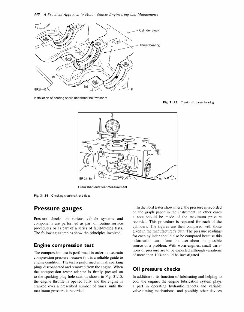
Pressure gauges
Pressure checks on various vehicle systems andcomponents are performed as part of routine serviceprocedures or as part of a series of fault-tracing tests.The following examples show the principles involved.
Engine compression test
The compression test is performed in order to ascertaincompression pressure because this is a reliable guide toengine condition. The test is performed with all sparkingplugs disconnected and removed from the engine. Whenthe compression tester adaptor is firmly pressed onto the sparking plug hole seat, as shown in Fig. 31.15,the engine throttle is opened fully and the engine iscranked over a prescribed number of times, until themaximum pressure is recorded.
In the Ford tester shown here, the pressure is recordedon the graph paper in the instrument, in other casesa note should be made of the maximum pressurerecorded. This procedure is repeated for each of thecylinders. The figures are then compared with thosegiven in the manufacturer’s data. The pressure readingsfor each cylinder should also be compared because thisinformation can inform the user about the possiblesource of a problem. With worn engines, small varia-tions of pressure are to be expected although variationsof more than 10% should be investigated.
Oil pressure checks
In addition to its function of lubricating and helping tocool the engine, the engine lubrication system playsa part in operating hydraulic tappets and variablevalve-timing mechanisms, and possibly other devices
Cylinder block
Thrust bearing
ER21– 42 K
Installation of bearing shells and thrust half washersFig. 31.13 Crankshaft thrust bearing
K ER 21–88
Crankshaft end float measurement
Fig. 31.14 Checking crankshaft end float
448 A Practical Approach to Motor Vehicle Engineering and Maintenance
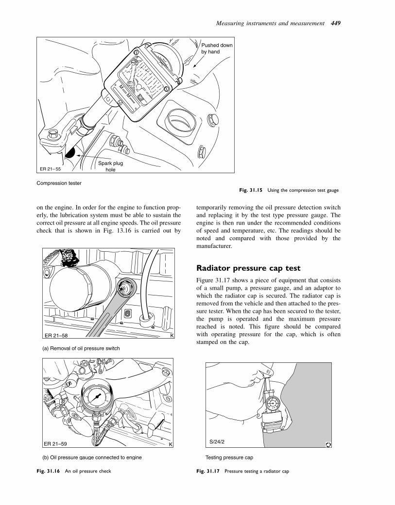
on the engine. In order for the engine to function prop-erly, the lubrication system must be able to sustain thecorrect oil pressure at all engine speeds. The oil pressurecheck that is shown in Fig. 13.16 is carried out by
temporarily removing the oil pressure detection switchand replacing it by the test type pressure gauge. Theengine is then run under the recommended conditionsof speed and temperature, etc. The readings should benoted and compared with those provided by themanufacturer.
Radiator pressure cap test
Figure 31.17 shows a piece of equipment that consistsof a small pump, a pressure gauge, and an adaptor towhich the radiator cap is secured. The radiator cap isremoved from the vehicle and then attached to the pres-sure tester. When the cap has been secured to the tester,the pump is operated and the maximum pressurereached is noted. This figure should be comparedwith operating pressure for the cap, which is oftenstamped on the cap.
M
M
Pushed downby hand
Spark plugholeER 21– 55
Compression testerFig. 31.15 Using the compression test gauge
ER 21–58 K
(a) Removal of oil pressure switch
ER 21–59 K
(b) Oil pressure gauge connected to engine
Fig. 31.16 An oil pressure check
S/24/2
Testing pressure cap
Fig. 31.17 Pressure testing a radiator cap
Measuring instruments and measurement 449
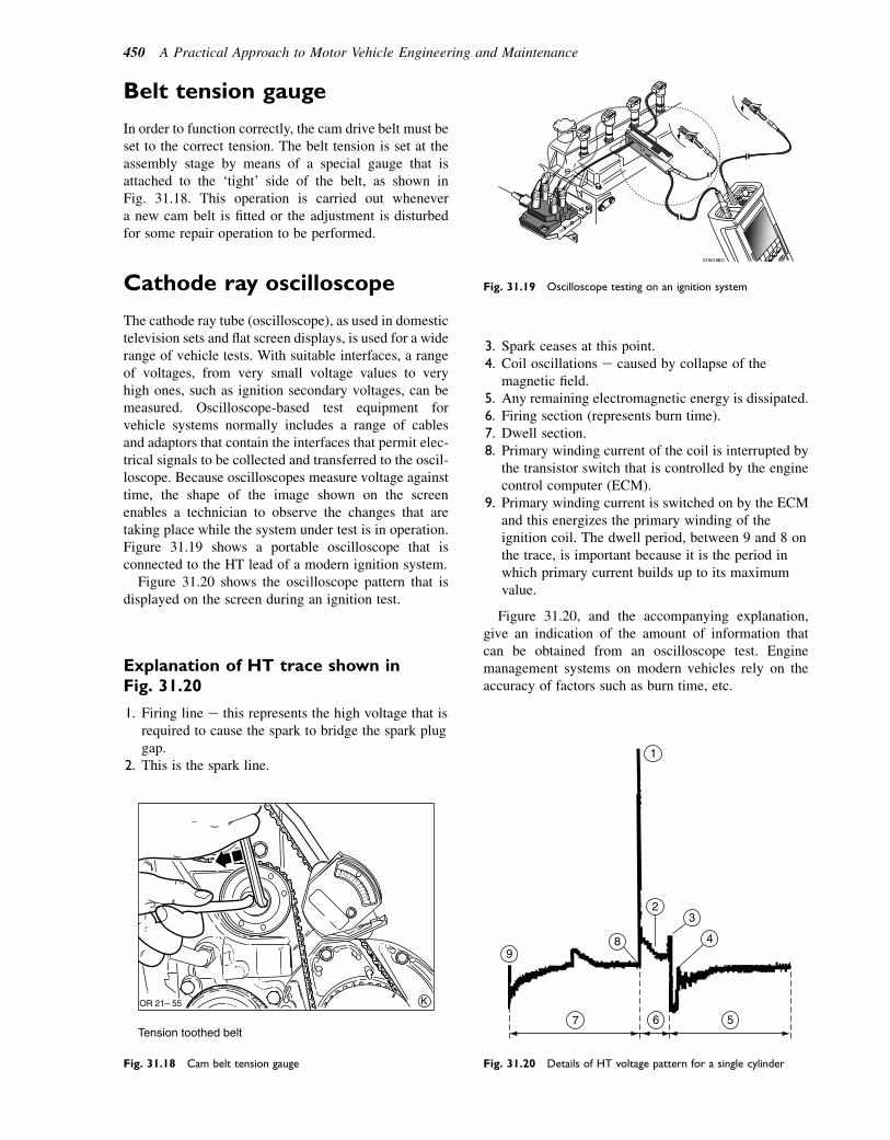
Belt tension gauge
In order to function correctly, the cam drive belt must beset to the correct tension. The belt tension is set at theassembly stage by means of a special gauge that isattached to the ‘tight’ side of the belt, as shown inFig. 31.18. This operation is carried out whenevera new cam belt is fitted or the adjustment is disturbedfor some repair operation to be performed.
Cathode ray oscilloscope
The cathode ray tube (oscilloscope), as used in domestictelevision sets and flat screen displays, is used for a widerange of vehicle tests. With suitable interfaces, a rangeof voltages, from very small voltage values to veryhigh ones, such as ignition secondary voltages, can bemeasured. Oscilloscope-based test equipment forvehicle systems normally includes a range of cablesand adaptors that contain the interfaces that permit elec-trical signals to be collected and transferred to the oscil-loscope. Because oscilloscopes measure voltage againsttime, the shape of the image shown on the screenenables a technician to observe the changes that aretaking place while the system under test is in operation.Figure 31.19 shows a portable oscilloscope that isconnected to the HT lead of a modern ignition system.
Figure 31.20 shows the oscilloscope pattern that isdisplayed on the screen during an ignition test.
Explanation of HT trace shown inFig. 31.20
1. Firing line e this represents the high voltage that isrequired to cause the spark to bridge the spark pluggap.
2. This is the spark line.
3. Spark ceases at this point.4. Coil oscillations e caused by collapse of the
magnetic field.5. Any remaining electromagnetic energy is dissipated.6. Firing section (represents burn time).7. Dwell section.8. Primary winding current of the coil is interrupted by
the transistor switch that is controlled by the enginecontrol computer (ECM).
9. Primary winding current is switched on by the ECMand this energizes the primary winding of theignition coil. The dwell period, between 9 and 8 onthe trace, is important because it is the period inwhich primary current builds up to its maximumvalue.
Figure 31.20, and the accompanying explanation,give an indication of the amount of information thatcan be obtained from an oscilloscope test. Enginemanagement systems on modern vehicles rely on theaccuracy of factors such as burn time, etc.
K OR 21– 55
Tension toothed belt
Fig. 31.18 Cam belt tension gauge
Fig. 31.19 Oscilloscope testing on an ignition system
7 6
89
5
2
1
3
4
Fig. 31.20 Details of HT voltage pattern for a single cylinder
450 A Practical Approach to Motor Vehicle Engineering and Maintenance
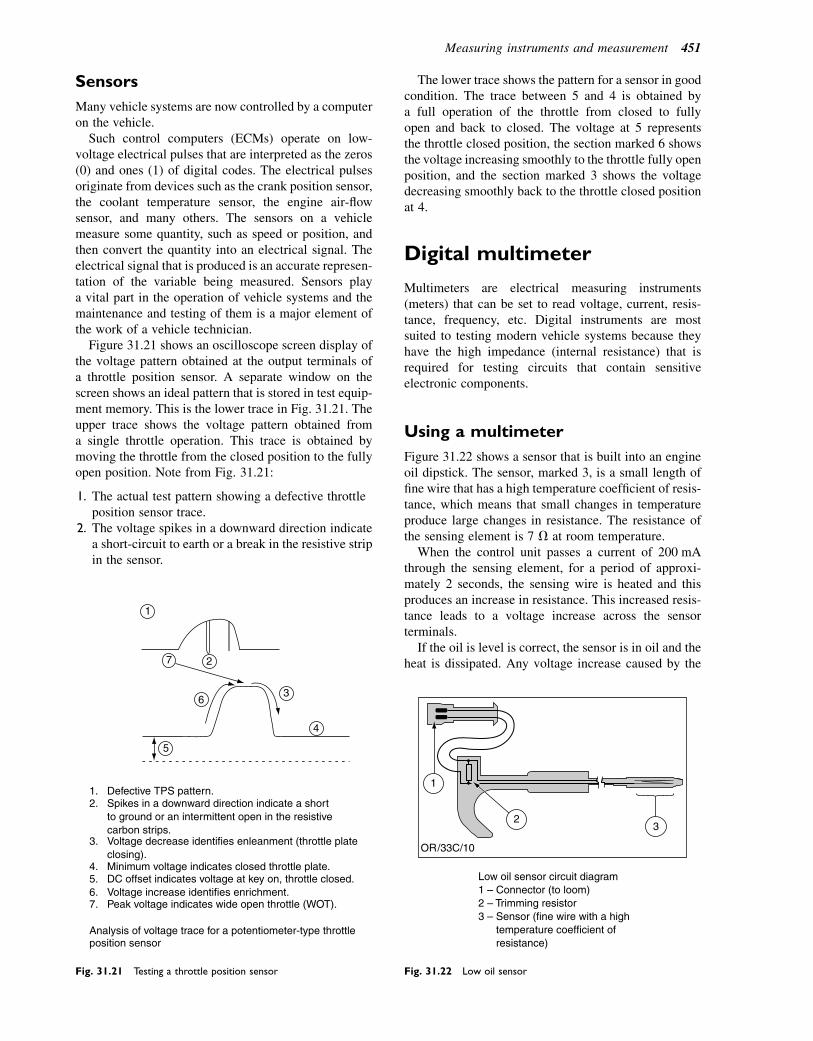
Sensors
Many vehicle systems are now controlled by a computeron the vehicle.
Such control computers (ECMs) operate on low-voltage electrical pulses that are interpreted as the zeros(0) and ones (1) of digital codes. The electrical pulsesoriginate from devices such as the crank position sensor,the coolant temperature sensor, the engine air-flowsensor, and many others. The sensors on a vehiclemeasure some quantity, such as speed or position, andthen convert the quantity into an electrical signal. Theelectrical signal that is produced is an accurate represen-tation of the variable being measured. Sensors playa vital part in the operation of vehicle systems and themaintenance and testing of them is a major element ofthe work of a vehicle technician.
Figure 31.21 shows an oscilloscope screen display ofthe voltage pattern obtained at the output terminals ofa throttle position sensor. A separate window on thescreen shows an ideal pattern that is stored in test equip-ment memory. This is the lower trace in Fig. 31.21. Theupper trace shows the voltage pattern obtained froma single throttle operation. This trace is obtained bymoving the throttle from the closed position to the fullyopen position. Note from Fig. 31.21:
1. The actual test pattern showing a defective throttleposition sensor trace.
2. The voltage spikes in a downward direction indicatea short-circuit to earth or a break in the resistive stripin the sensor.
The lower trace shows the pattern for a sensor in goodcondition. The trace between 5 and 4 is obtained bya full operation of the throttle from closed to fullyopen and back to closed. The voltage at 5 representsthe throttle closed position, the section marked 6 showsthe voltage increasing smoothly to the throttle fully openposition, and the section marked 3 shows the voltagedecreasing smoothly back to the throttle closed positionat 4.
Digital multimeter
Multimeters are electrical measuring instruments(meters) that can be set to read voltage, current, resis-tance, frequency, etc. Digital instruments are mostsuited to testing modern vehicle systems because theyhave the high impedance (internal resistance) that isrequired for testing circuits that contain sensitiveelectronic components.
Using a multimeter
Figure 31.22 shows a sensor that is built into an engineoil dipstick. The sensor, marked 3, is a small length offine wire that has a high temperature coefficient of resis-tance, which means that small changes in temperatureproduce large changes in resistance. The resistance ofthe sensing element is 7 V at room temperature.
When the control unit passes a current of 200 mAthrough the sensing element, for a period of approxi-mately 2 seconds, the sensing wire is heated and thisproduces an increase in resistance. This increased resis-tance leads to a voltage increase across the sensorterminals.
If the oil is level is correct, the sensor is in oil and theheat is dissipated. Any voltage increase caused by the
1
7 2
6
5
3
4
1.2.
3.
4.5.6.7.
Defective TPS pattern.Spikes in a downward direction indicate a shortto ground or an intermittent open in the resistivecarbon strips.Voltage decrease identifies enleanment (throttle plateclosing).Minimum voltage indicates closed throttle plate.DC offset indicates voltage at key on, throttle closed.Voltage increase identifies enrichment.Peak voltage indicates wide open throttle (WOT).
Analysis of voltage trace for a potentiometer-type throttleposition sensor
Fig. 31.21 Testing a throttle position sensor
Low oil sensor circuit diagram1 – Connector (to loom)2 – Trimming resistor3 – Sensor (fine wire with a high temperature coefficient of resistance)
1
3 2
Fig. 31.22 Low oil sensor
Measuring instruments and measurement 451
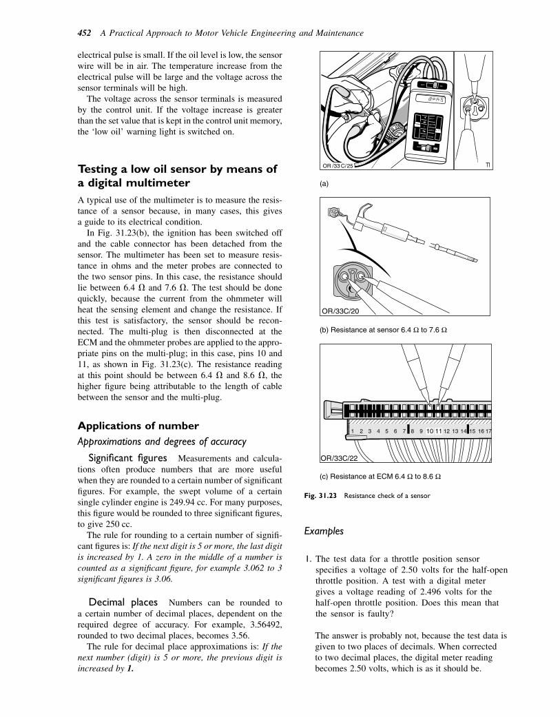
electrical pulse is small. If the oil level is low, the sensorwire will be in air. The temperature increase from theelectrical pulse will be large and the voltage across thesensor terminals will be high.
The voltage across the sensor terminals is measuredby the control unit. If the voltage increase is greaterthan the set value that is kept in the control unit memory,the ‘low oil’ warning light is switched on.
Testing a low oil sensor by means ofa digital multimeter
A typical use of the multimeter is to measure the resis-tance of a sensor because, in many cases, this givesa guide to its electrical condition.
In Fig. 31.23(b), the ignition has been switched offand the cable connector has been detached from thesensor. The multimeter has been set to measure resis-tance in ohms and the meter probes are connected tothe two sensor pins. In this case, the resistance shouldlie between 6.4 V and 7.6 V. The test should be donequickly, because the current from the ohmmeter willheat the sensing element and change the resistance. Ifthis test is satisfactory, the sensor should be recon-nected. The multi-plug is then disconnected at theECM and the ohmmeter probes are applied to the appro-priate pins on the multi-plug; in this case, pins 10 and11, as shown in Fig. 31.23(c). The resistance readingat this point should be between 6.4 V and 8.6 V, thehigher figure being attributable to the length of cablebetween the sensor and the multi-plug.
Applications of number
Approximations and degrees of accuracy
Significant figures Measurements and calcula-tions often produce numbers that are more usefulwhen they are rounded to a certain number of significantfigures. For example, the swept volume of a certainsingle cylinder engine is 249.94 cc. For many purposes,this figure would be rounded to three significant figures,to give 250 cc.
The rule for rounding to a certain number of signifi-cant figures is: If the next digit is 5 or more, the last digitis increased by 1. A zero in the middle of a number iscounted as a significant figure, for example 3.062 to 3significant figures is 3.06.
Decimal places Numbers can be rounded toa certain number of decimal places, dependent on therequired degree of accuracy. For example, 3.56492,rounded to two decimal places, becomes 3.56.
The rule for decimal place approximations is: If thenext number (digit) is 5 or more, the previous digit isincreased by 1.
Examples
1. The test data for a throttle position sensorspecifies a voltage of 2.50 volts for the half-openthrottle position. A test with a digital metergives a voltage reading of 2.496 volts for thehalf-open throttle position. Does this mean thatthe sensor is faulty?
The answer is probably not, because the test data isgiven to two places of decimals. When correctedto two decimal places, the digital meter readingbecomes 2.50 volts, which is as it should be.
Fig. 31.23 Resistance check of a sensor
452 A Practical Approach to Motor Vehicle Engineering and Maintenance
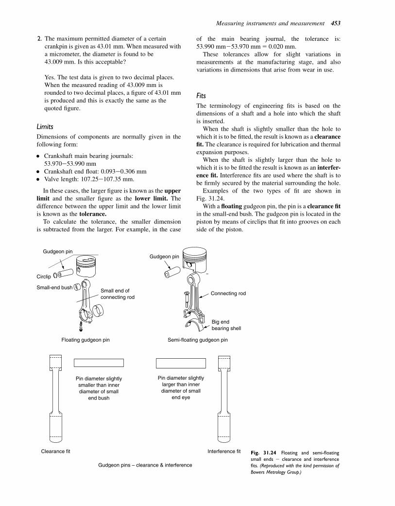
2. The maximum permitted diameter of a certaincrankpin is given as 43.01 mm. When measured witha micrometer, the diameter is found to be43.009 mm. Is this acceptable?
Yes. The test data is given to two decimal places.When the measured reading of 43.009 mm isrounded to two decimal places, a figure of 43.01 mmis produced and this is exactly the same as thequoted figure.
Limits
Dimensions of components are normally given in thefollowing form:
� Crankshaft main bearing journals:53.970e53.990 mm
� Crankshaft end float: 0.093e0.306 mm� Valve length: 107.25e107.35 mm.
In these cases, the larger figure is known as the upperlimit and the smaller figure as the lower limit. Thedifference between the upper limit and the lower limitis known as the tolerance.
To calculate the tolerance, the smaller dimensionis subtracted from the larger. For example, in the case
of the main bearing journal, the tolerance is:53.990 mm253.970 mm5 0.020 mm.These tolerances allow for slight variations in
measurements at the manufacturing stage, and alsovariations in dimensions that arise from wear in use.
Fits
The terminology of engineering fits is based on thedimensions of a shaft and a hole into which the shaftis inserted.
When the shaft is slightly smaller than the hole towhich it is to be fitted, the result is known as a clearancefit. The clearance is required for lubrication and thermalexpansion purposes.
When the shaft is slightly larger than the hole towhich it is to be fitted the result is known as an interfer-ence fit. Interference fits are used where the shaft is tobe firmly secured by the material surrounding the hole.
Examples of the two types of fit are shown inFig. 31.24.
With a floating gudgeon pin, the pin is a clearance fitin the small-end bush. The gudgeon pin is located in thepiston by means of circlips that fit into grooves on eachside of the piston.
Pin diameter slightly smaller than inner diameter of small
end bush
Pin diameter slightly larger than inner diameter of small
end eye
Clearance fit Interference fit
Semi-floating gudgeon pin
Connecting rod
Gudgeon pin
Big end bearing shell
Floating gudgeon pin
Gudgeon pin
Circlip
Small-end bushSmall end of connecting rod
Gudgeon pins – clearance & interference
Fig. 31.24 Floating and semi-floating
small ends e clearance and interference
fits. (Reproduced with the kind permission of
Bowers Metrology Group.)
Measuring instruments and measurement 453
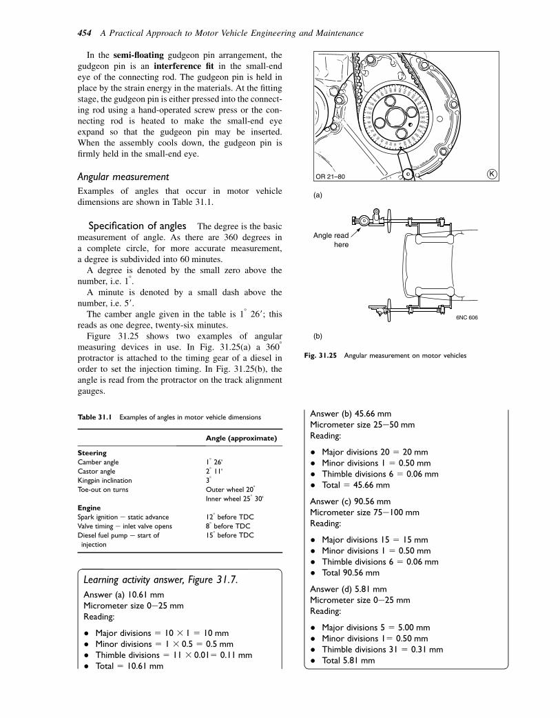
In the semi-floating gudgeon pin arrangement, thegudgeon pin is an interference fit in the small-endeye of the connecting rod. The gudgeon pin is held inplace by the strain energy in the materials. At the fittingstage, the gudgeon pin is either pressed into the connect-ing rod using a hand-operated screw press or the con-necting rod is heated to make the small-end eyeexpand so that the gudgeon pin may be inserted.When the assembly cools down, the gudgeon pin isfirmly held in the small-end eye.
Angular measurement
Examples of angles that occur in motor vehicledimensions are shown in Table 31.1.
Specification of angles The degree is the basicmeasurement of angle. As there are 360 degrees ina complete circle, for more accurate measurement,a degree is subdivided into 60 minutes.
A degree is denoted by the small zero above thenumber, i.e. 18.
A minute is denoted by a small dash above thenumber, i.e. 59.
The camber angle given in the table is 18 269; thisreads as one degree, twenty-six minutes.
Figure 31.25 shows two examples of angularmeasuring devices in use. In Fig. 31.25(a) a 3608
protractor is attached to the timing gear of a diesel inorder to set the injection timing. In Fig. 31.25(b), theangle is read from the protractor on the track alignmentgauges.
Learning activity answer, Figure 31.7.
Answer (a) 10.61 mmMicrometer size 0e25 mmReading:
� Major divisions 5 10 3 1 5 10 mm� Minor divisions 5 1 3 0.5 5 0.5 mm� Thimble divisions 5 11 3 0.015 0.11 mm� Total 5 10.61 mm
Answer (b) 45.66 mmMicrometer size 25e50 mmReading:
� Major divisions 20 5 20 mm� Minor divisions 1 5 0.50 mm� Thimble divisions 6 5 0.06 mm� Total 5 45.66 mm
Answer (c) 90.56 mmMicrometer size 75e100 mmReading:
� Major divisions 15 5 15 mm� Minor divisions 1 5 0.50 mm� Thimble divisions 6 5 0.06 mm� Total 90.56 mm
Answer (d) 5.81 mmMicrometer size 0e25 mmReading:
� Major divisions 5 5 5.00 mm� Minor divisions 15 0.50 mm� Thimble divisions 31 5 0.31 mm� Total 5.81 mm
OR 21–80
(a)
K
Angle read here
(b)
6NC 606
Fig. 31.25 Angular measurement on motor vehicles
Table 31.1 Examples of angles in motor vehicle dimensions
Angle (approximate)
Steering
Camber angle 18 26'Castor angle 28 11'Kingpin inclination 38
Toe-out on turns Outer wheel 208
Inner wheel 258 30'Engine
Spark ignition e static advance 128 before TDC
Valve timing e inlet valve opens 88 before TDC
Diesel fuel pump e start of
injection
158 before TDC
454 A Practical Approach to Motor Vehicle Engineering and Maintenance

Self-assessment questions1. Correct the following figures to two decimal places:
(a) 43.001(b) 0.768(c) 5.887.
2. Correct the following figures to the specifiednumber of significant figures:(a) 19.28 to three significant figures(b) 2.034 to three significant figures(c) 337.9 to three significant figures.
3. The capacity of a certain engine is calculated to be1998 cm3. For descriptive purposes, this figure isexpressed in litres. Calculate the engine capacity inlitres, correct to two significant figures.
4. 43 bolts, priced at 45.6 pence each, are to be addedto an account. Calculate the total amount for the 43bolts, correct to the nearest 1 penny. Give theanswer in pounds and pence.
5. Figure 31.26 shows a feeler gauge being used tocheck the gap in a piston ring. In order to performthis check:(a) the piston ring should just be pushed into the
cylinder(b) the piston ring should be gently pushed into the
cylinder using a piston as a guide to ensure thatthe ring is at right angles to the axis of thecylinder
(c) the ring gap must not exceed 0.001 mm(d) it does not matter if the ring is tilted in the
cylinder.6. Figure 31.27 shows a dial gauge that is set up to
measure the end float on an engine crankshaft. Endfloat is important because:(a) it allows space for lubrication of the crankshaft
thrust bearings(b) it provides free travel at the clutch pedal(c) it helps to keep the timing gears in alignment(d) it allows oil to be sprayed on to the cylinder
walls to lubricate them.
7. A crankpin has a diameter of 58.20 mm and the big-end bearing that is fitted to it has an internaldiameter of 58.28 mm. The clearance between thecrankpin and the big-end bearing is:(a) 1.0013 mm(b) 0.008 mm(c) 0.08 mm(d) 0.48 mm.
8. Figure 31.28 shows a feeler gauge marked 5 beingused to check the clearance between the cammarked 4 and the cam follower. This clearance isknown as the valve clearance and it is checkedwhen:(a) the cam is in the fully closed position(b) when the engine is at the recommended
temperature and the valve is in the fully closedposition
(c) the valve is fully open(d) the cam is at any position between valve fully
open and valve fully closed.9. The crankpin shown in Fig. 31.29 is measured at A,
B, C and D. Dimensions A and B are taken to
TR 21–234 K
Fig. 31.26 Checking a piston ring gap
K ER 21–58
Fig. 31.27 Checking crankshaft end float
1 4
3
2
5
RM1616
Fig. 31.28 Checking valve clearances
Measuring instruments and measurement 455
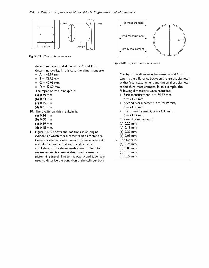
determine taper, and dimensions C and D todetermine ovality. In this case the dimensions are:� A5 42.99 mm� B5 42.75 mm� C5 42.99 mm� D5 42.60 mm.The taper on this crankpin is:(a) 0.39 mm(b) 0.24 mm(c) 0.15 mm(d) 0.01 mm.
10. The ovality on this crankpin is:(a) 0.24 mm(b) 0.00 mm(c) 0.39 mm(d) 0.15 mm.
11. Figure 31.30 shows the positions in an enginecylinder at which measurements of diameter aretaken in order to assess wear. The measurementsare taken in line and at right angles to thecrankshaft, at the three levels shown. The thirdmeasurement is taken at the lowest extent ofpiston ring travel. The terms ovality and taper areused to describe the condition of the cylinder bore.
Ovality is the difference betweeen a and b, andtaper is the difference between the largest diameterat the first measurement and the smallest diameterat the third measurement. In an example, thefollowing dimensions were recorded:� First measurement, a5 74.22 mm,
b5 73.95 mm� Second measurement, a5 74.19 mm,
b5 74.00 mm� Third measurement, a5 74.00 mm,
b5 73.97 mm.The maximum ovality is:(a) 0.22 mm(b) 0.19 mm(c) 0.27 mm(d) 0.03 mm.
12. The taper is:(a) 0.25 mm(b) 0.03 mm(c) 0.19 mm(d) 0.27 mm.
A B
Crankpin Crankpin
Web Web
C
D
Fig. 31.29 Crankshaft measurement
b
a
1st Measurement
2nd Measurement
3rd Measurement
Fig. 31.30 Cylinder bore measurement
456 A Practical Approach to Motor Vehicle Engineering and Maintenance
32Motor industry organizationsand career paths
Topics covered in thischapter
Qualifications and careersOrganizations in the motor trade
Qualifications
It is unfortunate that training and education tend to betreated as separate activities because this leads to diffi-culty when one is attempting to choose a course ofstudy or training. However, there are many fundamen-tals of motor vehicle engineering where the distinctionbetween training and education cannot sensibly bemade. With valve timing of an engine, it is essentialto understand cycles of engine operation, for examplethe four-stroke cycle. The knowledge required isknown as engine technology and is generally consid-ered to be education and therefore is part of thesyllabus for courses such as City and Guilds Progres-sion Award, BTEC First Diploma and Certificate,and similar qualifications. The actual setting of thevalve timing is a practical task and learning how todo it is considered to be training. The instructionand practice that leads to becoming proficient at thetask is also considered to be training and is consideredto be part of the National Vocational Qualification(NVQ). The outcome of this rather artificial distinctionbetween education and training is that educationalcourses contain much that contributes to one’s abilityto be a vehicle technician, while practical trainingcourses for NVQ also contain much that is of educa-tional value and, as a result, there are several routesthat people can follow in order to qualify as a motorvehicle technician.
Modern motor vehiclequalifications
National Vocational Qualification(NVQ), Scottish VocationalQualification (SVQ)
A list of skills that are required for competent perfor-mance of the tasks involved in maintenance and repairof vehicles has been devised and these skills are knownas National Occupational Standards, a typical examplebeing: Carry out routine vehicle maintenance. TheseOccupational Standards are used to design qualificationssuch as the NVQ. Because the work of a motor car tech-nician differs in some respects from that of a heavyvehicle technician, the training programme and coursecontent is not the same and NVQs have been designedto cater for these differences. The same is true of othermotor vehicle occupations, such as Auto ElectricalTechnician, Vehicle Body Repair Technician, PartsDepartment Technician, etc.
Levels
In the school years, levels of attainment tend to beexpressed in terms of year 2, year 6, etc., but in post-school training and education, the use of years asa description of a degree of difficulty involved insome learning step is not appropriate, and the trainingand education courses are classified in Levels. Theresult is that NVQs are available at several Levels, themain ones being at Levels 1, 2, and 3.
Studying for NVQ
To qualify for NVQ, it is necessary to demonstratecompetence, namely ability to perform a given task in
� 2011 Allan Bonnick and Derek Newbold. Published by Elsevier Ltd. All rights reserved

a normal work situation. However, as already explainedin the example of valve timing, the performance of a prac-tical task often requires an underpinning knowledge oftechnology. The result is that courses of study for NVQconsist of a balanced programme that takes place on thejob (in a workshop) for the practical and off the job (ina classroom) for the underpinning knowledge. NVQs inMotor Vehicle Maintenance and Repair certainly requirea good deal of underpinning technical knowledgetogether with practical training, and courses of educationand training are designed to cater for these factors.
Modern apprenticeships
Modern apprenticeships provide paid employment,practical training, and further education. During theapprenticeship, trainees must study for NVQ and KeySkills, and a Technical Certificate, such as City andGuilds or BTEC.
There are two levels of apprenticeships: foundationfor beginners e the training and education programmenormally lasts for approximately 1 year, and theadvanced apprenticeship, which lasts for approximately2 years.
Foundation modern apprenticeship
This first level of apprenticeship trains apprentices forLevel 2 NVQ and the associated Key Skills. In addition,a Technical Certificate is studied and this may bea BTEC First, City and Guilds, or Institute of MotorIndustry Certificate.
Advanced modern apprenticeship
Advanced Apprenticeships are designed to last for 2years. They prepare trainees for Level 3 NVQ and KeySkills, and a Technical Certificate, such as BTECNational or similar educational qualification, is studied.Apprenticeships should, in future, provide the mostattractive and efficient route to qualification and employ-ment in the vehicle maintenance and repair industry.
Courses in colleges
Many Further Education Colleges provide courses ofMotor Vehicle Studies. The courses vary from thosefor beginners, such as the City and Guilds ProgressionAward, to mainstream courses for BTEC NationalCertificates and Diplomas. Many of these courses arelinked to employers so that the students gain work expe-rience and this practical work, plus work done atcollege, may be taken into account when making a laterclaim for NVQ. For students who opt for study ina Further Education College, as opposed to school sixthform, the BTEC National and Higher National
programmes may provide a route into universityeducation.
Courses in secondary schools,technology colleges, etc.
Over the past few years, a number of secondary schoolshave offered motor vehicle courses and, with therenewed emphasis on vocational education, suchcourses are likely to become more widely available.
This book is designed for Levels 1 and 2 of currenttraining and education programmes but there areelements that extend into the Level 3 region ofsome topics. The text shows a large number of engi-neering concepts and it should help readers to makelinks between practical work and other subjects,such as science and number work, and thus assist inproviding students with a balanced educationalexperience.
Career prospects
When embarking on a career in the vehicle repair andmaintenance industry, thoughts about future jobs maynot be uppermost in one’s mind. As one’s career prog-resses this may change and it is useful to have an insightinto the types of jobs that may be open to people whohave trained as technicians. The following list gives anindication of the types of jobs that are often taken bypeople who started work as trainees or apprentices andwho, through gaining experience and qualifications,equipped themselves for promotion:
� Foreman� Technical receptionist� Service manager� Branch manager� Training instructor� Teacher/lecturer� Insurance engineers and assessors� Transport managers.
How to get there
There are approximately 30 000 businesses, large andsmall, in the UK that carry out vehicle repair and main-tenance. There are therefore many opportunities fortrainee technicians to advance to more senior positions,if they so desire. Holders of the jobs in the above listneed management skills and these are often taughtthrough specialized management courses. Managementstudies are also included in higher-level qualificationssuch as Higher National Certificates and Diplomas. Awell-presented curriculum vitae (CV) is likely to be anasset when applying for more senior positions.
458 A Practical Approach to Motor Vehicle Engineering and Maintenance

Apprenticeships and other opportunities for beginnersare likely to be advertised and promoted through thecareer service. College courses that contain an elementof work experience often lead to employment e it isprobably a good idea to shop around in your area tosee what courses are on offer.
Motor industry organizations
The Institute of the Motor Industry (IMI) and theInstitute of Road Transport Engineers (IRTE) are two
of the engineering/management institutes that manypeople engaged in motor vehicle maintenance and repairbelong to. These institutes have regional centres thatarrange lectures and other events relating to the industry.These events provide an opportunity to meet peoplefrom many different companies in an informal setting,in addition to allowing an opportunity to help peoplekeep abreast of developments. Two magazines, MotorIndustry Management published by the IMI and RoadTransport Engineer published by the IRTE, advertiseposts nationally, and the local press normally carriesadvertisements about job vacancies in their areas.
Motor industry organizations and career paths 459

Appendix A
A selection of answers to the numericalexercises
Chapter 2Q1. Exhaust.Q2. (c).Q3. (a) 118; (b) 358; (c) 388; (d) (i) 2248; (ii) 2208.Q4. Transfer port.Q5. Compression stroke.Q6. 720 degrees.Q8. 10.8:1.Q9. 60 mm.Q10. 679 cc.Q13. (a).Q15. (c).Q16. (c).
Chapter 3Q1. (a). 6.03 mm.Q3. (b).Q5. (c).Q6. (b).Q7. 0.16 mm.Q8. (b).
Q19. L.Q21. 0.040 mm.
Chapter 4Q1. (c).Q2. (a).Q4. 0.040 mm.
Chapter 6Q1. 0.24 mm.Q9. 440 N.
Q10. (a).
Chapter 8Q2. (a) 33.89 mpg; (b) 8.3 litres/100 km.Q3. (a) 6250 gallons; (b) £7500.Q4. 6135 gallons. 6250 e 6135 5 115 gallons.
Saving £138.
Chapter 10Q5. Once.Q6. 0.48 ms.Q7. Weaker.
Chapter 13Q2. 40.80 kJ.
Q10. 25A.
Chapter 14Q1. 31.2 kW.Q2. 134 kW; 89.6%.Q3. bp 5 95 kW; ip 5 118.8 kW.Q4. 38.4 kg/h.Q5. 6.7%.Q6. 91 mm.Q7. 28%.Q8. ip 5 33 kW; ME 5 76%.Q9. 5.08 m3/h.Q10. BTE 5 25.6%, 28.2%, 30%, 29.2%, 27.3%.
Chapter 16Q1. 1600 W.Q6. (b).
Q10. (a).
Q17.
Speed Difference in volume % Difference
300 1.6 18.2
600 0.8 7.5
900 1.4 12.3
Q18. 608.Q19. Element 2 minus 18.
Element 4 plus 28.
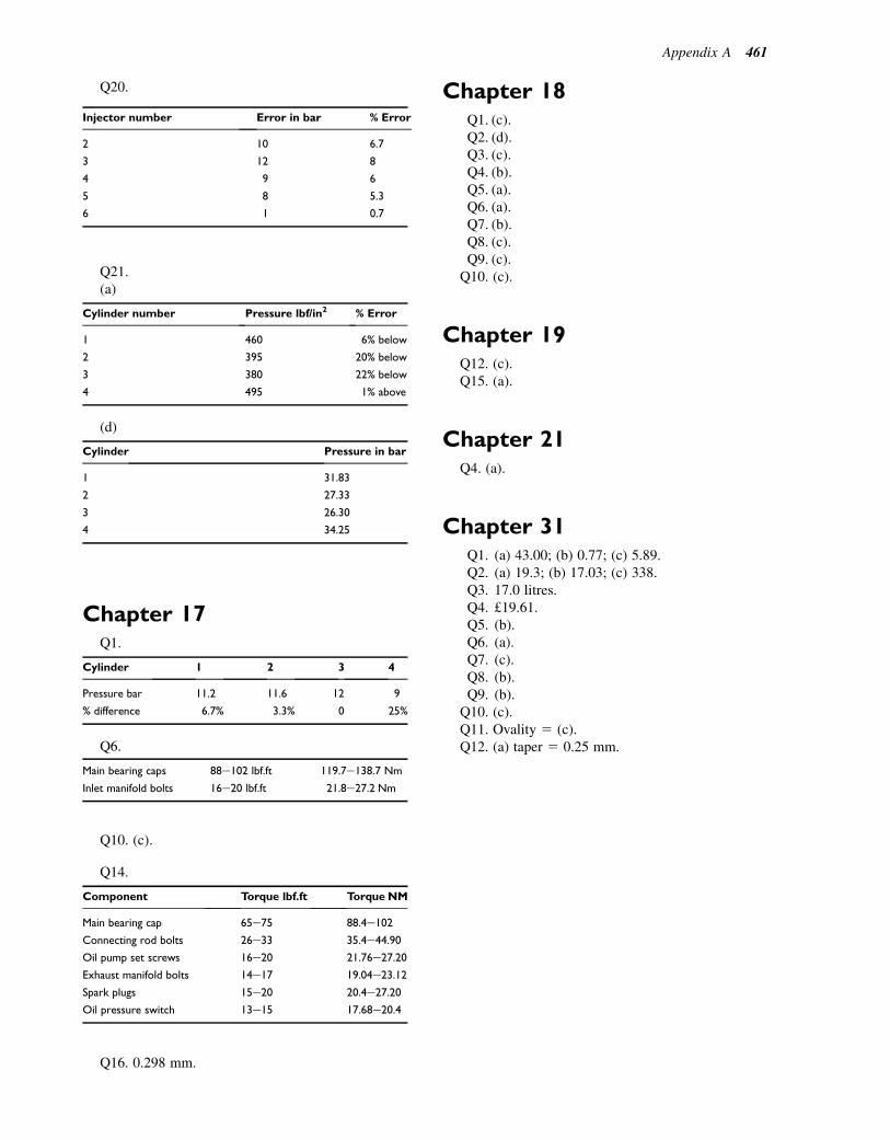
Q20.
Injector number Error in bar % Error
2 10 6.7
3 12 8
4 9 6
5 8 5.3
6 1 0.7
Q21.(a)
Cylinder number Pressure lbf/in2 % Error
1 460 6% below
2 395 20% below
3 380 22% below
4 495 1% above
(d)
Cylinder Pressure in bar
1 31.83
2 27.33
3 26.30
4 34.25
Chapter 17Q1.
Cylinder 1 2 3 4
Pressure bar 11.2 11.6 12 9
% difference 6.7% 3.3% 0 25%
Q6.
Main bearing caps 88e102 lbf.ft 119.7e138.7 Nm
Inlet manifold bolts 16e20 lbf.ft 21.8e27.2 Nm
Q10. (c).
Q14.
Component Torque lbf.ft Torque NM
Main bearing cap 65e75 88.4e102
Connecting rod bolts 26e33 35.4e44.90
Oil pump set screws 16e20 21.76e27.20
Exhaust manifold bolts 14e17 19.04e23.12
Spark plugs 15e20 20.4e27.20
Oil pressure switch 13e15 17.68e20.4
Q16. 0.298 mm.
Chapter 18Q1. (c).Q2. (d).Q3. (c).Q4. (b).Q5. (a).Q6. (a).Q7. (b).Q8. (c).Q9. (c).
Q10. (c).
Chapter 19Q12. (c).Q15. (a).
Chapter 21Q4. (a).
Chapter 31Q1. (a) 43.00; (b) 0.77; (c) 5.89.Q2. (a) 19.3; (b) 17.03; (c) 338.Q3. 17.0 litres.Q4. £19.61.Q5. (b).Q6. (a).Q7. (c).Q8. (b).Q9. (b).
Q10. (c).Q11. Ovality 5 (c).Q12. (a) taper 5 0.25 mm.
Appendix A 461

Appendix B
Conversion factors
Conversion factors and units
Quantity
and
symbol SI unit
Imperial
unit
Conversion
factor
Mass, m Kilogram, kg
Tonne
(1000 kg)
Pound, lb
(Ton 2240 lb)
1 lb5 0.454 kg
Length, l Metre, m
Millimetre, mm
Foot, ft
Inch, in
1 ft5 0.3048 m
1 in5 25.4 mm
Area, A Square
metre, m2Square ft, ft2 1 ft2 5 0.093 m2
Volume, V Cubic
metre, m3Cubic foot, ft3
Capacity, V Litre, L Gallon 1 gallon z4.5 litres
Force, F Newton, N Pound force,
lbf
1 lbf54.448 N
Power, P Kilowatt, kW Horse power,
hp
1 hp50.746 kW
Speed Kilometres per
hour, km/h
Miles per hour,
mph
1 km/h50.622 mile/hour
Velocity, v Metre/second,
m/s
Foot per
second, ft/s
1 ft/s50.3048 m/s
Torque, T Newton metre,
Nm
Pound foot,
lbf.ft
1 lbf.ft51.4 Nm
Pressure, P Pascal, Pa
Kilo pascal, kPa
Bar, bar
Lbf/in2
Atmosphere
1 Lbf/in2 56.89 kPa
1 atmosphere
z1 bar
Some other units:
The short, or USA, ton 5 2000 English pounds.The USA gallon 5 0.83 English gallons.

List of acronyms
ABS anti-lock braking systema.c. alternating currentACEA European Automobile Manufacturers’
AssociationAPI American Petroleum InstituteATDC after top dead centreATF Authorized Treatment FacilityATF automatic transmission fluid
BDC bottom dead centrebmep brake mean effective pressurebsfc brake specific fuel consumptionBTDC before top dead centre
CAN controller area networkCB contact breakerCFPP cold filter plugging pointCGLI City and Guilds of London InstituteCI/CIE compression ignition engineCRC cyclic redundancy checkCV constant velocity
d.c. direct currentDCU diagnostic and control unitDINDIS distributorless ignition systemDPA distributor pump applicationDPF diesel particulate filterDTC diagnostic trouble codeDTI dial test indicator
E4WS electronic four-wheel steeringEA Environment AgencyECM electronic control moduleECU electronic control unitEEPROM electrically erasable programmable read-
only memoryEGR exhaust gas recirculationELV End-of-Life Vehiclee.m.f. electromotive forceEOBD European on-board diagnosticsEP extreme pressureEU European UnionEVAP
FL front leftFR front rightFWD front-wheel drive
GEA Garage Equipment Association
HASAW health and safety at workHC hydrocarbonsHFC hydrofluorocarbonsHRW heated rear windowHSE Health and Safety ExecutiveHT high tension
IFS independent front suspensionimep indicated mean effective pressureIMI Institute of the Motor Industryip indicated powerIRS independent rear suspensionIRTE Institute of Road Transport EngineersISC idle speed controlISO International Standards Organization
KAM keep-alive memoryKPI kingpin inclination
LCD liquid crystal displayLED light-emitting diodeLGV large goods vehicleLPG liquid petroleum gasLT low tension
MACS Mobile air-conditioning systemsMAP manifold absolute pressure sensorMIL malfunction indicator light/lampMON motor octane numberMOT Ministry of TransportMUX multiplexer
NVQ National Vocational Qualification
OBD on-board diagnosticsOBD2 on-board diagnostics (USA)OFT Office of Fair TradingOHC overhead camshaftOHV overhead valve

PAS power-assisted steeringPCV positive crankcase ventilationp.d. potential differenceps pferdestarke (pulling power of a horse)PWM pulse width modulationPZT platinum, zirconium, titanium
RAM random-access memory (read and writememory)
ROM read-only memory (permanent memory)RON research octane numberrpm revolutions per minuteRTL resistor transistor logicRWD rear-wheel drive
SAE Society of Automotive EngineersSCR selective catalyst reduction
sfc specific fuel consumptionSHC specific heat capacitySRS supplementary restraint system
TDC top dead centreTRL British Transport Research LaboratoryTTL transistor-to-transistor logicTWI tread wear indicators
UJ universal joint
VCM vehicle condition monitoringVFD vacuum fluorescent displayVOSA Vehicle and Operator Services Agency
ZEV zero emissions vehicle
464 List of acronyms

Index
Note: Page references followed by “f” and “t” denote figures and tables, respectively.
Acceleration, 76, 83
Acceleration devices, 83
Acceleration enrichment, 76
Accelerator pump, 84f
Accountability, xxi
Ackermann principle, 278, 278f, 279f
Active or ‘live’ hydropneumatic suspension, 254e5, 255f
Active systems, 79
Actuator
rear steering, 307, 307f
tests, 430e1, 430f
valve timing, 12, 14fAdaptive ignition, 368e9
Adblue tank, 176f
Additives, 112
Aeration, 133
Air bags
for driver and front seat passenger, 419f
inflation, pyrotechnic device for, 421f
modules disposal, 422Air bleed compensation, 82
Air cleaner, 102f
Air conditioning, cooling system, 149e3, 151f, 152f
air conditioning fluid, 149e50
computer control of, 150e1
personnel qualifications, 152
refrigerant, 151e2training topics, 153
Air control valve, operation of, 103, 103f
Air cooled diesel engine, 129f
Air dam, 5f
Air filter, 102, 102f
Air flow meter, 103e4, 104f
Air horns, 401e2
repair and maintenance, 401e2Air intake manifold, 104, 105f
Air intake system, 103e4, 103f
Air resistance, 4
power used against, 4fAir supply systems, engine, 101e3, 102f
air control valve, operation of, 103, 103f
air filter, 102, 102f
temperature control of, 102e3, 102fAir suspension, 255e7, 258f
Air-cooling system, 128e9, 128f, 129f
advantages, 131
cooling air circulation, 128
disadvantages, 131
fans, types of, 128e9Air-flow sensor, 93e4, 94f, 104
Airefuel ratio values, 88
Alternating current, 332e6, 351
applications of, 332e6waveform, 332f
Alternative data loggers, 432, 432f
Alternator, 350e6
alternating current, 351
basic vehicle alternator, 350e1, 351f
bearings, 355
brushes and brush box, 354
component parts of, 353f
drive pulley and cooling fan, 355, 355f
full-wave rectifier, 352, 352f
output tests, 355e6, 355frectifier, 353e4
rotor, 352e3, 353f
single diode as a simple half-wave rectifier, 352
stator, 353, 353f
testing, 355, 356f
typical vehicle alternator, 352
voltage regulator, 354Alternator protection diode, 333
Alternator rectifier, 352, 352f
Alternator voltage regulator
protection diode in, 333fAltitude effect on engine performance, 166e7
Ampere, 325
Ampere-hour, 348e9
Anti-foaming agent, 244
Antifreeze, 142e3
function, 142
level checking, 142e3, 143fAnti-lock braking system (ABS), 272e4, 272f, 273f
modulator, 273f
warning light, 274
wheel speed sensor, 272e4Antioxidants, 112
Anti-roll bar, 254
Anti-theft devices, 399
burglar alarm, 399
coded ignition key and engine immobilizer system, 399Anti-wear additives, 112
Atkinson efficiency, 17
Atkinson engine cycle, 16e17
pressureevolume diagram for, 17fAtomization, 74e5
Atoms, 324, 324f
Authority, xxi
Authorized treatment facilities (ATFs), 5
Automatic brake adjuster, 270, 270f
Automatic gearbox, 239e43
epicyclic gear ratios, 239, 240f
friction elements that lock and unlock elements of gear set, 240
gear ratios, 240, 242f, 243f
gear set that produces gear ratios, 240
hydraulic system, 240
oil pressure in, 240e5
sensors, 242e3shift valves, 241e2
Automatic transmission hydraulic circuit, 244f
Automotive computer system, 310e18
adaptive operating strategy, 313
fault codes, 312e13
gateway, 316
multiplexing, 316e17, 317fnetworking and bus systems, 313
power supply and drivers, 316, 317fAxial flow fan, 128e9, 130f

Axial flow pump, 134e5
Axle shaft, 229e30Axles, 227
casings, 227
fully floating, 230, 233f
location, 252e3, 253f
misalignment, 299f
semi-floating axle, 229, 233f
three-quarter floating axle, 229e30, 233f
Back e.m.f., 333
Baffle plates, 115
Ball bearings, 231
Ball-joints, 287, 287f
Ballasted (series resistor) ignition circuit, 377f
Banjo axle casing, 227, 228f
Bath tub chamber, 43
Batteries, 346e50
capacity, 348e9
charging, 349
chemical effect of electric current, 346e7
construction, 348
case, 348, 348f
installation, 347f
lead acid vehicle battery, 347
relative density of electrolyte, 349
reserve capacity, 349e50
testing, 350
typical vehicle battery, 347e8Battery plate, 348f
Baulk-ring synchromesh gearbox, 216, 217f
Beam axle steering arrangement, 276, 276f
Bearing failure, 202e4, 203f
oil pump checks, 203f
crankshaft measurement, 203fBearing lubrication, 111f
Bearings, 31f, 55, 55f, 58, 59f, 355
alternator, 355
ball and roller, 210
combined radial and one-way thrust, 210
double-row journal, 231
metals, 55
copperelead, 55
leadebronze, 55
tinealuminium, 55
needle roller, 234
overhead camshaft, 58
overhead value, 58
parallel-roller journal, 232
plain, 231
shells, 55
fitting, 55, 55f
single-row deep groove radial, 231
taper roller, 232, 234Belt tension gauge, 450, 450f
Belt-driven camshaft drive, 23e4, 25f
Bi-metal elements, 143
Bi-metal spring, 103
Bimetal strip, 413
Binary, 314
Bio-fuels, 79
Bipolar transistors, 339
Birfield joint, 226
Bleeding
brakes, 274
fuel system, 183Block circuit diagram, for remote central locking, 393f
Bluecol hydrometer, 142, 143f
Body panels, 1
Body roll, 252f
Bolts
dimensions of, 434, 434f
drilling and tapping sizes, 436, 437t
strength, 438Boolean logic, 342
Bosch-type direct petrol injection, 97f
Boundary lubrication, 111
Brake adjustment, 269e70
automatic brake adjuster, 270, 270f
manual brake adjuster, 269, 269fBrake fluid, 271
Brake fluid reservoir, 267, 267f
Brake horsepower, 159
Brake linings, xix
Brake mean effective pressure, 165, 165f
Brake pipes and hoses, 267
Brake power, 158
torque and sfc, comparison, 164Brake pressure control valve, 270e1, 271f
Brake servo, 267e9, 268f, 269f
Brake thermal efficiency
petrol vs. diesel, 165, 166tBrake-light switch, 270f
Braking efficiency, 271
Braking systems, 263e74
anti-lock braking system (ABS), 272e4, 272f, 273f
in automatic gearbox, 242f
bleeding, 274
brake adjustment, 269e70
brake fluid, 271
brake fluid reservoir, 267, 267f
brake pipes and hoses, 267
brake pressure control valve, 270e1, 271f
brake servo, 267e9, 268f, 269f
brakes, types of, 263e4
braking efficiency, 271
handbrake, 265, 266f
hydraulic operation, 264e5
regenerative braking, 396f
split, 265e6
stop lamp switch, 270
tandem master cylinder, 266e7, 267f
vehicle, 263
wear indicators, 270, 270f
wheel cylinders, 265Breakout box, 428e30
oscilloscope tests at, 429e30Brush box, 354
Brushes, 354
Bulbs, 402e5. See also Headlamp
Burglar alarm, 399
Burroughs type tension gauge, 356f
Bus, 313
Bushes, 260
Business-line organization chart, xx
Bypass filter system, 118
Cable connectors
protection diode in, 416f
types of, 417fCable-operated clutch arrangement, 212f, 213f
Cable sizes, 411
Calibration, 182
Calipers, 447, 447f
Calorific value, 74
Cam, 19
466 Index

Cam and peg gearbox, 284
Cam profile, 182f
Cam-and-roller steering gearbox. See Worm and roller gearbox
Camber, 279e80, 279f, 294e5, 296f, 298f
Camshaft, 58e1, 58f
bearings, 58, 59f
overhead camshaft, 58
overhead value, 58
condition checks, 59
dimension checks, 59f
tappet rotation, 60e1
valve clearance, 61
valve train, 59e60Camshaft drive, 23e5
belt-driven, 23e4, 25fchain and sprocket, 23, 24f
condition checks, 24, 26f
gear train, 23, 25fCAN, logic levels, 314
Capacitance, 334e5
in circuit, 335, 336fCapacitive discharge, 335
Capacitors (condenser), 334, 335f, 362e3
in circuit, 335
connected in parallel, 335e6, 336f
and relay flasher unit and circuit, 408fCar wheels, types of, 290, 290f
Carbon canister, 70, 70f
Carbon dioxide, 77
global warming and, 91Carbon monoxide, 77
Carburation, 81
Carburettors, 81e6
acceleration, 83
cold starts, 83, 83f
constant-choke, 82
compensating jet and well, 82e3, 82f
diffuser tube, 82
constant-vacuum, 84e5, 85f
idling, 83, 84f
mixture
rich and weak, 82
strength, keeping constant, 82
progression, 83, 84f
running on, 83e4, 85fsimple, 81e2, 81f
limitation of, 81e2, 82fCarburizing, 54
Career prospects, 458e9
Carrier axle casing, 227, 228f
Cartridge filter, 120, 120f, 121f
Case hardening, 54
Castle nut, 436f
Castor action, 281
Castor gauge, 281e2, 281f, 298f
Catalysts, 78
Catalytic converter, 77
Cathode ray oscilloscope, 450e1, 450f
sensors, 451Cavitation, 142
Central door-locking systems, 392e3
circuit protection, 392
maintenance and fault tracing, 393
manual operation, 392
motor, 392
remote controller, 392
remote operation, 392
solenoid, 392
Centre-point steering, 279e80, 279f
camber, 279e80, 279f
kingpin inclination (KPI), 279, 280, 280fCentrifugal advance mechanism, checking, 386
Centrifugal fan, 129
Centrifugal pump, 135f
Centrifugal filter, 121
Chain and sprocket camshaft drive, 23, 24f
Chassis drop test, 299f
Choke, 81
Choke tube, 74
Circuit breakers, 413
Circuits, 408e16, 412f
cable sizes, 411
circuit protection fuses, 411e14circuit breaker, 413, 415f
connectors, 415e16
other circuit protection, 414
repair and maintenance, 416
colour code, 411
diagrams, 408e9, 411
electric circuit, 408f
elements list, system diagram, 410f
for headlamp, 407f
for indicator lamp, 407f
limit switch circuit for ‘off’ position of wiper arm, 395f
non-standard circuit symbols, 409f
for rear fog lamp, 407f
symbols, 326f, 409f
wiring loom (harness), 411Circular arc cam, 19
Clearance drill, 436
Clearance fit, 453
Clearance hole, 436
Clock, 310
Closed carbon cycle, 79
Clutch, 208e11
diaphragm-spring clutch, 208e10, 209ffriction-plate construction, 210
friction-plate materials, 210
hydraulic linkage, 211, 211f, 212f
linings, xix, 210e11
mechanical linkage, 211, 212f
multi-plate, 242f
multi-spring clutch, 208, 209f
operating mechanisms, 211e13
types of bearings used in, 231e4
wear properties, 210Clutch drag, 210, 212
Clutch faults, 212
Clutch judder, 210
Clutch linings, xix
Clutch slip, 212
Clutch vibration, 52
Coasting, overrun braking, 76
Coded ignition key and engine immobilizer system, 399
Coefficient of friction, 110, 110f
Coil ignition systems, 357
Coil polarity, 363, 363f
Coil springs, 248e9, 249f, 250f
Cold filter plugging point (CFPP). See Cloud point
Cold starting, 83, 83f, 94e5, 376, 376f, 377f
aids, 188e9
electrical connections, 189, 189f
heater plugs, 188, 188f
thermo-start unit, 188, 189fColour code, 411
Colour coding of resistors, 326f
Index 467

Combined radial and one-way thrust bearing, 232, 234f
Combustion
diesel engine, 172, 174f
gas leak, 146e7, 147f
chemical analysis for, 146e7
petrol engine, 75Combustion chambers, 40
design, factors that influence, 41e2shapes, 43f
types of, 42e4Combustion knock sensors, 367e8
Common rail diesel fuel system, 189e93, 190f, 191f
fuel rail and pressure-relief valve, 192
high-pressure pump, 191, 192f
pressure-regulating valve, 192
safety precautions, 192e3
sensors, 192e3Compensating jet and well air bleed system, 82e3, 82f
Compensator, 265
Compressed air equipment, xix
Compression height of piston, 27
Compression ignition engine. See Diesel engine
Compression pressure, 201t
Compression ratio, 10, 12f, 42, 42f
Computer, components of, 310e11, 311f
computer memory, 310
internal details of, 311, 313fComputer (ECU)-controlled systems, 310e23
automotive computer system, 310e18
computer memory, 310
diagnostics on, 424
electric throttle, 320e1
engine management systems, 318e20, 318f
stability control, 322e3traction control, 320
Computer-controlled transmission system, 312f
Computer memory, 310
clock, 310
EEPROMs, 310
keep-alive memory (KAM), 310
read and write, or random access memory (RAM), 310
read-only memory (ROM), 310Conductivity, 337
Conductors, 324
current entering and leaving, 330fConnecting rod, 30e2, 31f, 49e50
alignment checking, 32f
big-end eye dimensions, 32, 32f
condition checks, 30e2
gudgeon pin and small-end bush, 32
weight, 32Connectors, 415e16
Constant-choke carburettor, 82
compensating jet and well, 82e3, 82f
diffuser tube, 82Constant-energy ignition system, 364, 364f
Constant-load synchromesh mechanism, 217f
Constant mesh gearbox, 215e19
dog clutch for, 217f
principle, 217fConstant-pressure cycle, 169
Constant-vacuum carburettor, 84e5, 85fConstant-velocity universal joints, 225e7, 225
plunge joints, 226e7Rzeppa-type CV joint, 226, 226f
speed variation, 225, 225f
Tracta CV joints, 226, 226f
Weiss CV joint, 227
Contact breaker ignition systems, 335, 336f, 380e4
capacitor, testing, 383
contact points, condition of, 382
electrical condition of ignition coil, 383e4fault-finding principles, 380
high-tension (HT) leads, 383f, 384
HT sparking, checking for, 381, 381f
points gap, adjusting, 386e7, 387frotor, checking, 381e2, 381f
safety, 380
‘six-step’ approach, 380e1
visual checks, 381, 381f
voltage on the CB side of the coil, 382, 382fContact-breaker-type distributor, servicing, 388, 388f
Contact points, 382
Continuity tests, 427
Controller Area Network (CAN), 313e14
bus, 314
data transmission rates on, 314
layout, 314
cyclic redundancy check (CRC) error detection, 315
error protection, 315
nodes, 314e15, 314ftypes, 315
voltages, 314, 314f, 314tConverter lock-up clutch, 239f
Coolant temperature sensor, 94
thermistor type, 95fCooling fan, 355, 355f. See also Fans
Cooling systems, 126e54
antifreeze, 142e3
corrosion in, 142
engine air-cooling system, 128
engine core plugs, 144e5, 145fengine operating temperature ranges, 126f
engine temperature gauge, 143e4
fan belts, 142
fans, 138e42heating and ventilation, 149
direct ventilation, 149
indirect ventilation, 149
heat loss, 153
heat transfer, 127, 127f
interior heating and air conditioning, 149e53
liquid cooling, 130e1over-cooling, 127e8
overheating, 126e7
pressurized cooling system, 136e8, 137f
radiator and heater matrix, 132e4, 133fradiator blinds and shutters, 141, 142f
service and maintenance, 145e9
combustion gas leak, 146e7, 147f
fault diagnosis and repair, 145
low coolant levels and leaks, 145e6
poor coolant circulation, 147e9
pressure check, 146, 146f
thermostat, 135e6
types of, 128
water pump, 134e5Corrosion in cooling system, 142
cavitation, 142
direct attack, 142
electromechanical attack, 142
mineral deposits, 142, 143fCorrosion inhibitors, 244e5Couples, 52f
and distance between crank throws, 50Cracks in engines, condition check, 40, 41f
468 Index

Crankcase, 44, 44f, 46
Crankpins, 57
connecting rod eye, 57
diameter measurement, 57f
dimensions, 57
flywheel, 57e8, 57f
oil seals, 58, 58fCrankshaft, 30, 31f, 54e8, 54f
bearings, 55, 55f
bearing metals, 55
copperelead, 55
leadebronze, 55tinealuminium, 55
bearing shells fitting, 55, 55f
condition checks, 56
end float, 56, 56f
main bearings, 56, 56f
crankpins, 57
connecting rod eye, 57
diameter measurement, 57f
dimensions, 57
flywheel, 57e8, 57f
oil seals, 58, 58f
four-cylinder engine, 55f
heat treatment, 54
layout, 47e8
six-cylinder-in-line crankshaft and firing order, 47e8, 48fv8 crankshaft and firing order, 48, 48f
nitriding, 54e5
thrust bearing, 448fCrankshaft damper, 52, 52f
Crankshaft sensor, checking, 430f
Crash gearboxes, 215
Crown wheel and pinion, 228, 230f, 232f
Crown wheel teeth workings, 231f
Cruising speed, light engine load, 76
Crumple zones, 2e4
Current, measurement, 328e9
Customer(s)
categories, xxii
informed, xxii
new, xii
non-informed, xiiexxii
regular, xxiiCustomer’s collection points, xiv
Cutting out, 388
Cycle of operations, engine, 8
Cylinder balance test, 200f
Cylinder block, 44, 44f
bore wear, 45f
condition checks, 45
wet liner protrusion for clamping, 45e6, 45fCylinder head, 8, 39, 39f
bolt-tightening sequence, 39, 41f, 201f
condition checks, 39e40
flatness checking, 202f
gasket failure, 198e202, 199f
causes of, 202t
condition check, 40, 40f, 41fCylinder leakage test, 146, 146f
Cylinder liners, 44e5, 44f
Cylinder pressure vs. crank angle, 161e2, 162e3f
Damper. See Suspension systems
Darlington pair, 340, 340f
Dashboard fusebox, 415f
Data (control bus), 314
Dead axle, 227
Decarbonising, 389
Degas system, 137f
Delegating, xxi
Delivery valve, 180
Detergent/dispersant additives, 112
Detonation, 42, 388
Diagnostic and control unit (DCU), 419e20
Diagnostic trouble codes (DTCs), 200, 373, 373f, 374t, 424
limitations of, 425e6, 426f
structure of, 424e5Diagonal split, braking system, 266
Dial test indicators (DTIs), 228, 231f, 447, 447f
brake disc run-out, 447
crank shaft end float, 447Diaphragm-spring clutch, 208e10, 209f
Die nut, 437, 438f
Die stock, 435
Dielectric, 334
Dies, 435, 437f
Diesel cycle, 169, 170f
Diesel engine, 168e76, 169f
combustion, 172, 174f
products, 174
construction, 170e1
diesel cycle, 169, 170f
diesel fuel, 172
dual combustion cycle, 169e70, 170femission control, 175e6, 175f
emission limits, 174e5, 174t
four stroke, 168
turbulence, 172
induction stroke, 172, 173f
two stroke, 170, 170fDiesel fuel, 172
cloud point, 172
flash point, 172
pour point, 172Diesel fuel systems, 177e89, 177f, 178f
bleeding, 183
cold starting aids, 188e89
common rail diesel fuel system, 189e93, 190f, 191fDPA or rotary fuel injection pump, 184e5, 184f, 185f, 186f
fuel filters, 178e9, 179f
injector pump, 179e82
lift pump, 177e8lubrication, 182e183
phasing and calibration, 182
spill timing, 183, 183fDiesel knock, 172
Diesel particulate filters (DPFs), 79
Differential, 228e9, 232fDifferential lock, 222, 223f
Diffuser tube air bleed system, 82
air bleed compensation, 82fDigital electronic ignition, 365
Digital (programmed) ignition system, 364e5, 365f
Digital meter, 428
Digital multimeter, 451e4
applications of number, 452e4
accuracy, approximations and degrees of, 452
angular measurement, 454, 454f
fits, 453e4, 453f
limits, 453
testing low oil sensor by, 452, 452f
using, 451e2Diode, principle, 351f
Diode protection resistor, 338
Dipped beam principle, 404f
Index 469

Direct current (DC), 352
Direct drive, 219
Direct ignition systems, 366, 368f
engine construction, 170e1, 171ftesting, 373
Direct petrol injection, 96e7, 97f
idling and light load crushing, 96
medium and full-load conditions, 96e7Direction indicator lamps, 407e8
Disc brake, 264, 264f
Disc filter, 120e1, 121f
Discipline, xxi
Distributor cam, 375
Distributor pump application (DPA) fuel injection pump. See Rotary
fuel injection pump
Distributor shaft, 364
Distributor-type ignition system, testing, 372, 372f
Distributorless ignition system, 366, 367f
testing, 372e373, 372f, 373tDog clutch, 217f
Door mirrors, electrically operated, 399e400, 400fDopants, 337
Doping, 337
Double-acting wheel cylinder, 265, 265f
Double-row journal bearing, 231, 234f
self-aligning, 231e2, 234fDouble springs, 21e2, 22f
Downstream oxygen sensor, 318e19, 319f
Drag, 141
Drag coefficient, 4
Drag link, 282
Drilling sizes, 436, 437t
Drive belt tension, 356f
Drive pulley, 355, 355f
Drive shafts, 225
Driving hub assembly, 288, 289f
Drop forging, 54
Drum brake, 263, 263f
Dry sump lubrication, 121e2, 121f
Dual combustion cycle, 168, 169e70, 170f
Dual mass flywheel, 52e3, 53f
Dummy first motion shafts, 57
Dunlop optical alignment gauge, 283f
Duty cycle, 96, 96f
Dwell angle, 373e4, 374f, 375f, 386, 387f
Dynamic ignition timing, 385e6
Dynamometer
for high-speed engines, 158e67
for low-speed engines, 158f
Earth circuit
voltage drop on, checking, 359fEEPROMs, 310
Electric current, 324
effects of, 325e8Electric fuel pump, 68f
Electric horns, 400e2
air horns, 401e2
basic principles, 401f
wind tone horns, 401Electric motor effect, 331e2, 331f, 332f
Electric power-assisted steering, 303e4, 305fElectric shock, 380
Electric throttle, 320e1
drive by wire, 320e1Electrical circuits, fault tracing in, 426e32
actuator tests, 430e1, 430f
breakout box, 428e30
continuity tests, 427
digital multimeter, 426, 426f
intermittent faults, 431
logic probe, 431, 431f
resistance tests, 428, 428f
sensor tests, 430
voltage drop test, 427, 427fElectrical connections, 189, 189f
Electrical fuel pump, 68f
Electrical overload, 397
effects of, 397Electrical power sources, 325f
Electrical safety, xix
Electrical units, 325e8
Electrically operated door mirrors, 399e400, 400f
Electrically operated windows, 402, 402e3f
Electricity, 329e32Electrochemical effect, 346
Electrolyte, relative density, 349
Electromagnetic clutch, 153f
Electromagnetic induction, 330e1, 331fElectromagnetic pulse generators, 364
constant-energy ignition system, 364
digital (programmed) ignition system, 364e5, 365fElectromechanical attack, 142
Electromotive force, 324e5
Electronic control module (ECM), 192, 313, 368, 392
controlled electric fan, 148fElectronic control unit (ECU), 87. See also
Computer (ECU)-controlled systems
fault codes, 246
-controlled power-assisted steering, 303, 304f
servotronic operation, 303Electronic ignition system, 363
Electronic module, 369, 369f
Electronic principles, 336e42Electronic type distributor, servicing, 370e1
Electronically controlled automatic transmission, 227e46, 237f
automatic gearbox, 239e43
fluid couplings, 237e9
maintenance and fault tracing, 243e6Electronic-type distributor, servicing, 370e1, 371f
static timing, setting, 370e1Electrons, 324, 324f, 337
Emission control, 77
End float, 56
End-of-life (ELV) directive, 4
implementation of, 5
meaning of, 4Engine core plugs, 144e5, 145f
Engine immobilizer system, 399f
Engine management systems, 318e20, 318f
downstream oxygen sensor, 318e19, 319fexhaust gas recirculation, 319e20, 319f
Engine oil, SAE viscosity classification, 112
Engine power, 158
Engine speed ratio, 164
Engine speed sensor, 94, 95f
Engine temperature gauge, 143e4
Engine
compartment
fusebox, 414f
wiring loom, 413f
components, 8, 9f
dimensions, 9f
operating range, 164
performance, characteristics, 162e3, 163fEpicyclic differential, 224e5, 224f
470 Index

Epicyclic gear ratios, 239, 240f
Epicyclic gear set, 241f
principle used for locking elements of, 241fEpitrochoid, 16
Ethylene-glycol anti-freeze solution, 142
European emission standards EURO, 4, 76
European on-board diagnostics (EOBD), 99, 317e18
EVAP system, 71e2
Evaporator, 150
Excess fuel device, 181e2Excessive fuel consumption, 388
Exhaust catalyst, 318
Exhaust emissions, 97, 99
EU5 regulations, 97
in-service stage, 97e8Exhaust gas analyser, 97
Exhaust gas recirculation (EGR), 77e8, 78f, 96, 176, 176f, 319e20,
319f
Exhaust oxygen sensor vaults, 99
Exhaust valve, 8
Exhaust valve lead, 10
Expansion tank, 138
Failure to start, 389
Fan belts, 142
Fans, 138e42
automatically-controlled, 140
directly driven, 140
drives, 140e1
free-wheeling, 140
torque limiting, 141
variable pitch, 141
variable speed, 140e1, 141f
electrically driven, 138, 139f, 140f
fan blades, 138e9, 140f
surrounded by cowl or attached to radiator, 139e40
with swept tips, 139
free-wheeling, 140Fault codes, 312e13
Fault diagnosis, engine, 198e207
engine faults, 198
mechanical conditions, 198e204components, 198, 199f
Feeler gauges, 441e7, 442f
non magnetic, 441F-gas, 149
Filter circuits, 341
Filters, 70
Final drive, 227e8
hypoid bevel, 227e8
servicing and adjustments, 228
spiral bevel, 227
straight bevel, 227, 230f
worm and wheel, 228Firing interval, 50
Firing orders, 47
Flasher unit, 408
Fleming’s rule, 332, 332f
Flight recorder (data logger) function, 431e2, 431f, 432f
Fluid couplings, 237e9
fluid flywheel, 237e8, 238f
torque converter, 238, 239fFluid flywheel, 237e8, 238f
Fluke multimeters, 426f
Flywheel, 57e8, 57f
assembly, 30Fog lamp circuit, 407f
Followers, 19
Forward bias, 337
currentevoltage in, 338fFour cylinder in-line engine balance, 50, 50f
Four-cylinder-in-line engine crankshaft, 47f
Four stroke compression ignition engine, 168, 169f
Four stroke cycle of operations, 9
Four wheel drive layout, 7, 7f
advantages, 6
disadvantages, 6Four wheel steering, 304e9, 305f, 306fFour-wheel drive system
power transmission, 221e2operation, 222
steering, 304e9, 305f, 306f
ECU inputs and outputs, 306f
front steering sensors, 305e7Free electrons, 324
Free-wheeling device, 140
Friction, 110
coefficient of, 110, 110f
reduction of, 110e11Friction brakes, 263
Friction clutch, 208
Friction pad wear indicator, 270
Friction plate
construction, 210
materials, 210Front axle and one rear wheel split, braking system, 266
Front engine, rear wheel drive layout, 5e6, 6f
advantages, 5
disadvantages, 6Front-hub assemblies
driving hubs, 288, 289f
non-driving hubs, 288, 288fFront main steering angle sensor, 305e6
Front/rear split, braking system, 266, 266f
Front screen washers, 397f
Front steering sub-sensor, 306e7, 307f
Front wheel drive layout, 5, 5f
advantages, 5
disadvantages, 5Front-wheel drive system
gearbox, 219e20, 222fFuel cell, 79, 80f
Fuel consumption, excessive, 388
Fuel delivery, 98
Fuel filters, 98
Fuel gallery, 69
Fuel-injected engine air intake system, 103e4, 103f
air flow meter, 103e4, 104f
air intake manifold, 104, 105f
idle air control, 104, 105f
throttle position sensor, 104, 104fFuel lift pump, 177e8Fuel-line pressure, 98, 98f
Fuel pipes, 98
Fuel pump, 68e9
mechanical, 69, 69fFuel rail and pressure-relief valve, 192
Fuel retrievers, 71, 71f
draining without, 71Fuel return, 69, 69f
Fuel system. See Diesel fuel systems; Petrol fuel system
Fuel tank, 67e8
fixings, 68fFuelling map, 88, 88f
Full-flow filter, 120, 120f
Full-flow system, 118
Index 471

Full load, 96e7
Full-wave rectifier, 352, 352f
Fully-sealed pressurized cooling system, 138
Fundamental frequency, 50
Fuse types, 413f
Fusebox, 414f
Garage industry, xv
Gas discharge lamps, 405e7, 406f
Gas-pressurized dampers, 258
Gasket failure, 198e202, 199f
Gasket-type plug seat, 378e9, 379fGear lever, 215
Gear pump, 117, 117f
Gear ratio, 214, 214f, 219, 219f
Gear selection mechanisms, 217e18, 218fGear train camshaft drive, 23, 25f
Gearbox, 214e15, 216f
baulk ring synchromesh, 216, 217f
constant load synchromesh, 217f
constant mesh, 215e19interlocking mechanism, 218f
Generator, principle, 351f
Global warming and CO2, 91
Gudgeon pin
diameter of, 32f
offset, 27, 28f
Half-wave rectifier, 352, 352f
Hall effect
sensor, 364e5, 366f
distributor, 371f
pulse generator, 371Hall element, 365
Handbrake (parking brake), 265, 266f
Harmonic balancer, 50
Harmonics, 50, 51f
Header tank, 133, 134f
Headlamp
alignment, 405
screws, 406f
using marked wall, 405f
circuit, 407f
dipping, 405
ordinary twin-filament headlamp bulb, 403
quartz halogen twin-filament headlamp bulb, 404, 404f
sealed beam headlamp unit, 405fHealth and safety, xvi
topics, xviHeat energy balance, 166
Heat exchangers, 122, 122f
Heat loss, 153
Heat path, 378
Heat sink, 340e1, 341f
Heat transfer, 127, 127f
Heater plugs, 188, 188f
Heating and ventilation system, 149, 150f
direct ventilation, 149
indirect ventilation, 149Height corrector, 254
Helical gear, 117
Helicoil inserts, 437, 438f
Hemispherical combustion chamber, 44
Hesitation, 388
High-pressure pump, 191, 192f
High rate discharge tester, 349
High-speed, heavy load running, 76
High tension (HT)
leads, 384
sparking, 381High-voltage electrical energy, distribution, 374e6, 375f, 376f
Holes, 337
Honda valve system, 11e12, 13f
Horizontally opposed engine, 37, 38f
Hotchkiss drive, 221f
Hybrid vehicles, 1
Hydraulic accumulator, 254
Hydraulic chain tension adjuster, 24f
Hydraulic cylinder, 265
Hydraulic dynamometer, 159f
Hydraulic fluid, 302
Hydraulic linkage, 211, 211f, 212f
Hydraulic power-assisted steering, 302e3, 302f
Hydraulic system of brakes, 264e5
master cylinder, 264e5, 264f, 265f
principle, 264, 264fHydraulic tappet, 23, 23f
Hydrocarbons (HC), 75e6, 77
Hydrodynamic lubrication, 111
Hydrogas suspension, 254, 254f
Hydrogen, 79e80
Hydrolastic suspension, 253, 254f
Hydrometer, 349f
Hydro-pneumatic suspension. See Hydrogas suspension
Idle air control, 104, 105f
Idle speed control, 95, 95f
Idling, 76, 83, 84f, 96
Ignition circuit, 317f, 363f
Ignition coil, 362f
primary and secondary circuit of, 362f, 363fIgnition systems, 361e90
adaptive ignition, 368e9capacitor, 362e3
coil polarity, 363, 363f
direct ignition systems, 366, 368f
distributorless ignition system, 366, 367f
electromagnetic pulse generators, 364
electronic ignition systems, 363
fault tracing
in contact breaker ignition systems, 380e4
maintenance and repair of, 369e80
inducing high-tension (HT) secondary voltage, 361e2
knock sensing, 367e8opto-electronic sensing, 365e6, 366f, 367f
principle of operation, 361
producing high voltage to cause ignition, 361
refinements, 366
secondary circuit, 362
for spark ignition engines, 361e9, 362fIgnition timing, 12e14, 15f, 384e6
dynamic timing, 385e6
setting, 12, 385
static timing, 384e5Impedance, 336, 337f
Independent front suspension, 250
Independent rear suspension, 250
Independent suspension systems, 250e7
active (live) hydropneumatic suspension, 254e5, 255f
air suspension, 255e7, 258f
axle location, 252e3, 253f
hydrogas suspension, 254, 254f
hydrolastic suspension, 253, 254f
rear wheel ‘suspension steer’, 255, 256f, 257f
rubber suspension, 253, 253fIndicated power, 159, 160f
472 Index

calculation of, 160Indicators, 407e8
circuit, 407f
‘flasher’ unit, 408Indirect injection engines
construction, 171, 171fInductance, 333
Induction stroke, 172, 173f
Inductive reactance, 334, 334f
Inductive-type ignition pulse generator, 369, 369f
Hall-type sensor tests, 370, 370f, 371f
opto-electronic trigger sensor, 370, 371f
resistance check, 370, 370fInformed customers, xxii
Injector pump, 179e82
cam shapes, 182, 182f
delivery value, 181, 181f
excess fuel device, 181e2
multi-element, 179e81, 180f, 181fInjector test bench, 100f
Injectors. See Multi-hole injectors; Single-hole injectors
Inlet valve lag, 10
In-line engine, 37, 38f
four-cylinder layout, 38fInstrument displays, types of, 419f
Instrumentation, 416e18
thermal type gauges, 416e17
vacuum fluorescent display gauge, 417e18
vehicle condition monitoring (VCM), 418
voltage stabilizer, 417Insulators, 324
Intake manifold, 104, 105f
Integrated circuits (I/C), 341. See also Circuits
Intercooler, 107, 107f
Interference fit, 453
Interior heating, 149e53
Intermittent faults, 431
Intermittent wiper control, 395e6, 396f
Internal combustion engines, 1, 158e7
altitude effect on engine performance, 166e7
brake mean effective pressure, 165, 165f
brake power, torque and sfc, comparison, 164
brake thermal efficiency, petrol vs. diesel, 165, 166t
cylinder pressure vs. crank angle, 161e2, 162e3f
dynamometer for high-speed engines, 158e67engine performance, characteristics, 162e3, 163f
engine power, 158
brake power, 158
heat energy balance, 166
horsepower, 159
indicated power, 159, 160f
calculation of, 160
mean effective pressure, 159e60mechanical efficiency of engine, 162
Morse test, 162, 162t
number of working strokes, 160e1pferdestrake, 159
specific fuel consumption vs. engine speed, 163e4, 164f, 164t
thermal efficiency, 165
indicated, 165
torque vs. engine speed, 163, 163f
volumetric efficiency and air flow, 163, 163fInternal micrometer, 444, 446f
Inertia switch, 70
ISO 9141 diagnostic bus system, 315
Jack, xvii
Job card, xxii
Joule, 153
Journal bearing, 231e2Judder, 213
Jump starting, 414
Keep-alive memory (KAM), 310
Kevlar body panel, 3f
Kingpin inclination (KPI), 279, 280, 280f, 298f
K-line diagnostic bus, 316f
Knock sensing, 367e8, 368f
combustion knock sensors, 367e8Knocking, 75
‘L’ split, 266
Lambda (l), 88
Laser type tracking equipment, 297, 298f
Layshaft gears, 215
Lead acid vehicle battery, 347
Leaf springs, 248, 249f
Lenz’s law, 333
Levelling valves, 254
Leverage, 214, 215f
Lift pumps, 177e8Lifting equipment, xvii
Light load crushing, 96
Light-emitting diodes (LEDs), 338e9
voltage and current in, 339Light vehicles, 1
types of, 2f
wheels, 288e90, 290fLighting, 402e8
circuit components bulbs, 402e5ordinary twin-filament headlamp bulb, 403, 404f
quartz halogen twin-filament headlamp bulb, 404, 404f
sealed beam units, 404e5
stop and tail lamps, 404
circuit tests, 427
direction indicators, 407e8
‘flasher’ unit, 408
headlamp
alignment, 405
circuit, 407, 407f
dipping, 405
gas discharge lamps, 405e7rear fog light circuit, 407, 407f
regulations for, 402
safety, 406Limit switch circuit, for off position of wiper arm, 395f
Liquid cooling system, 130e1
advantages, 131e2
disadvantages, 132
fault chart, 144t
pump-assisted circulation, 130e1, 131f
thermo-syphon system, 130Liquid crystal displays (LCD), 418
Liquified petroleum gas (LPG), 79
Live axle, 227
Load dump, 414
Location notch, in bulb base, 404f
Lock nuts, 435, 436f
Logic devices, 341e2
Logic gates, 343
circuit, 342fLogic probe, 431, 431f
Lost spark system, 366
Low compression in engine cylinders
causes, 201tLow oil sensor, 451f
Index 473

Low power, 388
Low-profile tyres, 292
Lubricants, xix, 110e11
friction, 110Lubrication system, 113e22, 114f, 182e3
dry sump lubrication, 121e2, 121f
main components, 114
oil coolers, 122, 122f
oil filter, 118e21, 119f
oil function, 114e15, 115f, 116f
oil level indicators, 115e16, 116f
oil pump, 116e18pressure-relief valve, 118, 118f
sump function, 115, 116f
total loss lubrication, 122Lucas headlamp alignment machine, 405f
Magnetic field
around straight conductor, 330, 330f
caused by coil of wire, 330, 331f
direction of, 330fMagnetic poles, attraction and repulsion of,
330f
Magnetism, 329e32
Manual brake adjuster, 269, 269f
Master cylinder, 264e5, 264f, 265f
tandem, 266e7, 267fMean effective pressure, 159e60
Measuring instruments, 441e7, 442f
belt tension gauge, 450, 450f
calipers, 447, 447f
cathode ray oscilloscope, 450e1, 450f
dial test indicators, 447, 447f
digital multimeter, 451e4
feeler gauges, 441e7internal micrometer, 444, 446f
Mercer cylinder gauge, 444
metric external micrometer, 442e4, 443f
micrometers, 442
pressure gauges, 448e9
vernier calipers, 441Mechanical defects, 397e9
arms, 399
blades, 397e9
linkage, 399Mechanical efficiency of engine, 162
Mechanical fuel pump, 69, 69f
Mechanical linkage, 211, 212f
defects, 399Mercer cylinder gauge, 444, 446f
Meters. See individual entries
Methanol-based anti-freeze, 142
Metric external micrometer, 442e4, 443f
Microcontroller, 311
Micrometers, 442
for larger diameters, 444, 445f
reading in, 443e4, 444fscales, 444f, 445f
Microprocessor-controlled vehicle system semiconductors, 337f
Mineral deposits, 142, 143f
Mineral oil, 111
Misfiring, 388
Mixture enrichment, 76
Modern clutch lining materials, 211
Modern motor vehicle qualifications, 457e8
courses, 458
levels, 457
modern apprenticeships, 458
advanced modern apprenticeship, 458
foundation modern apprenticeship, 458Modulator, 273f
Morse test, 162, 162t
Motor defects, 397
Motor fuels, 74e80
airefuel ratio, 75
calorific value, 74
combustion, 74
products, 74e5
detonation, 75
emissions, causes of, 76e7exhaust emissions, factors affecting, 75e6
controlling methods, 77e80
octane rating, 75
petrol engine combustion, 75
pre-ignition, 75
properties, values of, 74tMotor industry organizations, xv, 459
Motor trade business, 458e9
Motor vehicle maintenance and repair industry, xiv
type of work in, xviMoulded linings, 210e11
Multi-cylinder engines, 37e46
cylinder arrangements, 37
structure, 37e46Multi-element injection pump, 181e2
Multi-grade oils, 112
Multi-hole injectors, 187, 187f
Multiple-plate clutches, 213
in automatic gearbox, 242fMultiplexing, 316e17, 317fMulti-point injection, 91e6, 91f
air-flow sensor, 93e4catalyst, 92
cold start, 94e5
continuous, 91e2
coolant temperature sensor, 94
duty cycle, 96, 96f
engine speed and piston position sensor, 94, 95f
exhaust gas recirculation, 96
fuel requirement, 93
idle speed control, 95, 95f
oxygen sensor, 92e3
petrol injector, 95e6, 96fsequential, 92
throttle position sensor, 93, 93fMulti-spring clutch, 208, 209f
Mutual induction, 384
National Occupational Standards, 457
National Vocational Qualification (NVQ), 457e8
Natural frequency of vibration, 21
Naturally aspirated engines, 105
Needle roller bearing, 234, 234f
Needle valve, 185
Negative castor, 281, 281f
Negative offset, 280
Negative steering roll radius, 280
Negative temperature coefficient of resistance semiconductor, 338, 338f
Neon test lamp, 381
Networking and bus systems, 313
Neutral pressure zones, 149
New customers, xxii
Nitriding, 54e5
Nitrogen oxides (NOx), 76e7Non-driving hub assembly, 288, 288f
Non-independent suspension systems, 248e50
474 Index

coil springs, 248e9, 249f, 250fleaf springs, 248, 249f
torsion bar, 250, 251fNon-informed customers, xxii
Non-standard circuit symbols, 409f
NOR gate, 342f
Nozzle, 187e8, 187f
N-type semiconductor, 337
Nucleus, 324
Number of working strokes, 160e1Nuts, dimensions of, 434
Nyloc self-locking nut, 436f
OBD2, 317
Occasional four-wheel-drive system
gearbox, 222, 223fOctane rating, 75
Offset, 27, 28f
Ohm, 325
Ohm’s law, 327, 327f
Ohmmeter, 328, 329f
Oil, xvii
control piston ring, 29f
coolers, 122, 122f
film, 114
filter, 114, 118e21, 119f, 120f
cartridge filter, 120, 120f, 121f
centrifugal filter, 121
disc filter, 120e1, 121f
full-flow filter, 120, 120f
gallery, 114
handling and waste disposal, 113, 113f
pressure indicator, 114
pressure test, 204f
quantity, 112
seals, 58, 58f
sources, 111e12
types of, 112e13Oil coolers, 122, 122f
Oil filters, 118e21, 119f, 120fOil function, 114e15, 115f, 116f
Oil level indicator, 115e16, 116f
Oil pressure test, 204f, 448e9, 449f
Oil pump, 114, 116e18
gear pump, 117, 117f
rotary pump, 117e18, 117fvane type pump, 118, 118f
Oil seals, 58, 58f
Oil wedge, 115
On-board diagnostics (OBD), 424e6
fault codes (DTCs), 424
scan tool, 424Open circuit, 329, 329f
Open-loop systems, 89
Opposed piston engine, 140
Opto-electronic sensing, 365e6, 366f, 367f
Oscilloscope, 429e30
cathode ray, 450e1, 450fOtto four-stroke cycle, 8
compression ratio, 10, 12f
engine, 8, 10f
ignition timing, 12e14, 15f
operation, 9, 11f
valve timing, 10
and emissions, 11e12
setting, 10e11, 13f
variable valve lift, 12, 13f
variable valve timing, 12, 13f, 14f
Over-cooling, 127e8
Overdrive, 219
types of, 220fOverhead camshaft engines (OCE), 22e3, 22f, 60
Overhead value engines (OHV)
operating mechanism, 22, 22f
valve train, 59, 59fOverheating, 126e7, 388
Oxidation inhibitors, 244
Oxides of nitrogen (NOx), 76e7Oxygen sensor, 92e3
second exhaust, 93f
Pen junction, 337, 338f
diode behaviour, 337e8P-type semiconductor, 337
Panhard rod, 252
Parallel-roller journal bearing, 232, 234f
Particulate matter, 77
Particulate trap, 175e6
Passenger protection, 1e4
crumple zones, 2e4
side impact protection, 4Passive systems, 79
Pawl-type free-wheel, 182
Pent roof combustion chamber, 43
Permanent four-wheel drive system
gearbox, 222, 223f, 224f
via viscous coupling, 223, 224fPermanent magnet motor, 393
Permanent magnets, 329e30
Permittivity, 335
Petrol air mixture, 15
Petrol engine
combustion process, 75
compression test, 200f
emissions, 90e1, 90fPetrol fires, xix
Petrol fuel system, 67e73, 67f
carbon canister, 70, 70f
filters, 70
fuel retrievers, 71, 71f
draining without, 71
fuel return, 69, 69f
fuel tank, 67e8
inertia switch, 70
maintenance and repair, 71e2
pipes, 69e70
precautions, 71
pump, 68e9
mechanical fuel pump, 69, 69f
safe use of, 70e1Petrol injection system, 95e6, 87f, 96f
airefuel ratio values, 88
direct petrol injection, 96e7, 97f
fuelling map, 88
lambda, 88
maintenance and repair, 97e9
exhaust emissions, 97
performance checks, 99
service checks and repairs, 98
multi-point injection, 91e6, 91f
oscilloscope pattern for, 98f
principle, 87
sequential, 92
single point injection, 89e91, 90f
types of, 89, 89fPferdestrake, 159
Index 475

Phasing, 182
Photo-diode, 339
Pick-up assembly, 364f
Piezo-electric combustion knock sensor, 369f
Pinking, 388
Pintaux nozzles, 187e8, 187fPintle, 187, 187f
Pipes/pipelines, 69e70
Piston rings, 27e29, 29f
side clearance of, 29e30, 30f, 33fPiston skirt, 27, 27f
damage at, 30fPiston slap, 27
Pistons, 25e30, 26f, 49e50
condition checks, 29e30
diameter measurement, 29, 29f
melting temperature, 25e6, 26f
offset gudgeon pin, 27, 28f
position sensor, 94
structure, 26e7, 27f
thermal expansion, 26
thrust side of, 27, 28fPivot points, 281
Plain bearings, 231
Plastigage, 56
Platinum, 78
Plenum chamber, 128
Plug reach, 378
Plunge joints, 226e7
Ply, 291
Pneumatic spring, 254
Polarity, 363
Policy
company, xvi
safety, xvi, xixPoor coolant circulation, 147e9
blocked air passages through radiator grill, 149
blocked radiator, 148e9, 148fdefective fan, 147
defective thermostat, 147
defective water pump, 147
electric fan, 147e8, 148fPoor starting, 389
Poppet valves, 19
Positive castor, 281
Potentiometer, 104
Potentiometer-type air-flow sensor
oscilloscope trace for, 425fPour point depressants, 112
Power-assisted steering, 302e9
control valve, 303f
diagnostics, 309
ECU-controlled, 303, 304f
electric, 303e4, 305f
four-wheel steering, 304e9, 305f, 306f
hydraulic, 302e3problems, 308t
Power curves, 164, 196f
Power resistors, 325
Power transmission
by clutch, 213
to driving wheels, 219e25
differential lock, 222
four-wheel drive, 221e2front-wheel drive, 219e20
occasional four-wheel-drive system, 222
permanent four-wheel drive system, 222, 223
rear-wheel drive, 220e1, 222f
transfer box, 222, 222f, 223f
viscous coupling and epicyclic differential, 224e5Powerbus, 317f
Pre-ignition, 127, 388e9
causes, 42Pressure cap, 136e7, 137f
testing, 146, 146fPressure checks, 246
cooling system, 146Pressure gauges, 448e9
engine compression test, 448, 449f
oil pressure checks, 448e9, 449fradiator pressure cap test, 449, 449f
Pressure plate, 208
Pressure-regulating valve, 192
Pressure regulator, 90
Pressure-relief valve, 118, 118f
Pressure test on cooling system, 146
Pressure valve, 136
Pressurized cooling system, 136e8, 137f
fully-sealed system, 138
pressure cap, 136e7, 137f
semi-sealed system, 138, 138fPre-tensioner
operation of, 420f
pyrotechnic seatbelt pre-tensioners, 422Primary circuit, 362f, 363f
Primary force, 49, 49f
Primary winding, 325, 333
Problem solving, six step approach, 380
Progression, 83, 84f
Propeller shafts, 225, 225f
Protection diode, in cable connector, 416f
Pulse generators, 369
Pulse width modulation, 95
Pump-assisted circulation, 130e1, 131fPurging the canister, 70
Pyrotechnic device, for air bags inflation, 421f
Pyrotechnic seatbelt pre-tensioners, 422
Quality control, xxiii
Quartz halogen bulb
locating, 404f
twin-filament headlamp bulb, 404, 404f
Rack and pinion gearbox, 285e6
Rack and pinion steering, 286f, 305f
Radial flow fan, 129, 130f
Radial flow pump, 135, 135f
Radiator, 132e4, 133f
cross-flow, 133, 133f
film core, 132
separate coolant tubes, 132e3separate expansion or header tanks, 133, 134f
tube and corrugated film, 132, 134f
tube and fin, 132Radiator blinds and shutters, 141, 142f
Radiator matrix, 132e4Radio interference, 384
Random access memory (RAM), 310
Read-only memory (ROM), 310
Rear engine, rear wheel drive layout, 6, 7f
advantages, 6
disadvantages, 6Rear fog lamp circuit, 407f
Rear hub bearing and axle shaft arrangements, 229e30
fully floating axle, 230, 233f
lubrication, 230
476 Index

semi-floating axle, 229, 233f
three-quarter floating axle, 229e30, 233fRear main steering angle sensor, 307e9, 308f
Rear screen washer, 396, 397f
Rear steering actuator, 307, 307f
Rear wheel drive, 5e6, 220e1Rear-wheel drive system
gearbox, 220e1with coil spring suspension, 221, 222f
Rear wheel suspension steer, 255, 256f, 257f
Reception, xxi
Reciprocating engines, 8
Recirculating ball gearbox, 284e5, 285fRecords, xxiii
Rectifier, 353e4
Refrigerant, 149
Regenerative braking, 394, 396f
Regular customers, xxii
Regulating valve, 184
Relay, 330
Release bearing, 208
Relief value, 114
Reluctor, 364f
Remote central locking system, 394f
block circuit diagram for, 393fResistance, 99
tests for, 428, 428f
at control unit and sensor, 428, 429fResistance value, 326, 429
Resistors, 325e6
colour coding of, 326f
in parallel, 328, 328f
in series, 327e8, 327fRetarders, 263
Reverse gear arrangement, 216, 218f
Rhodium, 78
Ride height, 300f
Ride height levellers, 256
Ridge dodger, 28
Road springs, 258
Road test, 246
Rocker cover, 38e9, 39f
Rocker shaft, 284
Roller bearings, 231
Roller-type brake tester, 271f
Rolling friction, 110, 111f
Rotary engines, 16, 16f
Rotary fuel injection pump, 184e5, 184f, 185f, 186f
injectors, 185e8operation method, 186
Rotary pump, 117e18, 117fRotor arm, 375f
Rotor checking, 381e2
Rotor field winding, 354
Rotor of alternator, 352e3, 353f
Routine maintenance, 198
Routine service, 61
Rubber bushes, 253
Rubber suspension, 253, 253f
Rule of, 9, 61
Running on, 388
Rust and corrosion inhibitors, 112
Rzeppa joint, 227
Rzeppa-type CV joint, 226, 226f
SAE viscosity classification, 112
Safe working practices, 384
Safety (Health and Safety at Work), xv, 204
Scavenging, 42
Scottish Vocational Qualification (SVQ), 457
Screen washers, 396e9
electrical defects, 397
effects of, 397
electrical overload, 397
maintenance and repair, 396e7
mechanical defects, 397e9arms, 399
blades, 397e9
linkage, 399
motor defects, 397
motor, 397
switch, 397
rear screen washer, 396
repairs and fault tracing, 397Screen wipers, 393e6, 395f
blades parking, 393e4
control of, 393
operating current testing using ammeter, 398f
operation, 393
intermittent operation, 395e6
two-speed operation, 395
regenerative braking, 394Screws, 437e8, 439f
heads, 439f
strength, 438, 439f
threads, 434
pitch and angle, 435f
pitch gauges, 435fSealed beam units, 404e5, 405f
Seals, 40, 58, 58f, 62f
Second gear ratio, 220f
Secondary cell, 346
Secondary force, 49, 49f
balancer, 50, 51fSecondary ignition circuit, 362
Secondary voltage, 361e2
Secondary winding, 333, 325
Selective catalyst reduction (SCR) system, 78e9, 79f, 175e6
Self adjusting hydraulic tappet, 23, 23f
Self induction, 362
Semiconductors, 324
Semi-permanent keep alive memory (KAM), 310
Semi-sealed pressurized cooling system, 138, 138f
Sensor tests, 430
Sensors, 192e3, 427
flap, 104
unit, 416Sequential injection, 92
Service bay, xxiii, xxiv
Shaft lubrication, 111f
Shells, 324
Short-circuit, 329, 329f
Shroud, 139
Shutter, 141
Shuttle valve solenoid, 272
Side impact protection, 4, 4f
Silencer, 102
Silicon, 324, 337
Silicone fluid, 141
Simple carburettor, 81e2, 81f
limitation of, 81e2, 82fSingle-acting wheel cylinder, 265
Single-cylinder engine rotating parts, balance of, 50
couples, 50, 52f
crankshaft damper, 52, 52f
dual mass flywheel, 52e3, 53f
Index 477

Single-cylinder engine rotating parts, balance of (Continued )
individual components, 50e1
torsional vibration, 52, 52f
vibration damper, 52, 53fSingle coil spring, 21, 22f
Single-hole injectors, 187
Single point injection, 89e1, 90f
emissions and control by feedback, 90e1global warming and CO2, 91
Single-row deep groove radial or journal bearing, 231, 234f
Six-cylinder-in-line crankshaft and firing order, 47e8, 48f
Six diode rectifier, 353e4, 354f
Six step approach to problem solving, 380
Sliding contacts, 111
Sliding mesh gearbox
four gear ratios of, 216fSlip, 44, 212, 238e9Slip ring, 355
Slow running, idling system, 75
Solenoid, 95, 330, 358f
shift valves, 245fSolenoid contacts, 358e9
Spanners
dimensions of, 434
and thread diameter, 435tSpark gap (electrode gap), 378, 377f
Spark ignition, 361e9, 362f
Spark timing, 12e14Sparking plugs, 376
cleaning, 379e80compression pressure, 376e8, 377f
construction, 377f
electrodes gap, 379e80
electrodes polarity, 363
gasket or tapered seat, 378e9, 379f
heat range of, 378, 378f
maintenance and servicing, 379e80, 379f, 380f
over-heated, 389
plug reach, 378, 378f
spark gap, 377f, 378
temperature, 376
testing, 380Specific fuel consumption vs. engine speed, 163e4, 164f, 164tSpecific gravity, relative density, 349
Specific heat capacity (SHC), 153
Speed sensor, 308f
Spigot bearing, 57, 208
Spill cut-off, 180
Spill timing, 183, 183f
Splash lubrication, 116f
Split axle casing, 227, 228f
Split braking systems, 265e6
diagonal split, 266
front/rear split, 266, 266fSplit casing, 227
Spur gear, 117
Squish, 43, 171
Stability control, 322e3, 322f
CAN connections for, 322fStall test, 245e6
Stalling speed, 237
Starter motor, 356e60, 356f
circuits, testing, 357
gear ratio, 356f
operating lever, 357f
pinion over-run protection, 357f
starter solenoid, 357f
starter terminal voltage, 357e9
voltage test, 358fStarting, 107
failure, 389
problems, 389Static timing, 384e5, 385f
checking, with engine running, 386
Hall effect pulse generator, 371, 371f
variable-reluctance pulse generator, 371
setting, 385Stator, 353, 353f
Steering
Ackerman layout, 278, 278f, 279f
alignment, tracking and toe in, 282
angles, 297f
beam-axle, 276f
centre-point, 279e80
gearboxes, 282e7
ball-joints, 287, 287f
cam and peg, 284
rack and pinion, 285e6, 286f
recirculating ball, 284e5, 285f
steering rack adjustment, 286e7, 286f, 287f
worm and roller, 284, 285f
geometry, 278
layouts, for light vehicle, 277, 277f
rack adjustment, 286e7, 286f, 287f
roll radius, 280, 280f, 281f
toe-out on turns, 282
track, 294Stop and tail lamps, 404
Stop lamp switch, 270
Stratified charge formation, 96
Streamlining, 4
Stroboscopic timing lamp, 386f
Studs, 434, 435f
removal of broken, 436
removers, 434
strength, 438SU carburettor, 85
Sulphur dioxide, 77
Sump, 46, 46f, 114
Supplementary restraint systems (SRS), 418e22
air bags and seat-belt pre-tensioners, 420e1
rotary coupler, 421
components, 420f, 421
handling, 421
safety precautions, 421e2
storage, 421e2Surge protection in relay, 333e4, 334f
Suspension arm, 221, 254
Suspension dampers, 248
gas-pressurized dampers, 258
materials used in, 258e60operation, checking, 258
twin-tube telescopic damper, 257e8Suspension links, 258
Suspension systems, 248e62
alignment and geometry, 260
independent, 250e7
maintenance checks, 260
materials used, 258e60
non-independent, 248e50
suspension dampers, 248
unsprung mass, 248Swept volume, 8
Swing beam steering, 278f
Swivel axis inclination, 280
Synchromesh gearbox, 215e16
478 Index

Synthetic oil, 112e13
grades, 113
Tandem master cylinder, 266e7, 267f
Taper roller bearing, 232e4, 234f
Tapered-type plug seat, 378e9, 379f
Tappet rotation, 60e1Tapping drill, 436
Tapping sizes, 436, 437t
Taps, 435, 437f
Telescopic shock absorber, 259f
Temperature coefficient of resistance, 329, 329f
Temperature indicators, 143
Temperature sensor, 94
Test card, 359
Texa OBD data logger, 432f
Theft alarm circuit, 400f
Thermal efficiency, 42, 165
indicated, 165Thermal type gauges, 416e17, 418f
vacuum fluorescent display gauge, 417e18
vehicle condition monitoring (VCM), 418
voltage stabilizer, 417Thermistor, 94, 417
Thermo-start unit, 188, 189f
Thermostat, 135e6
bellows type, 135e6, 136ftesting, 136, 136f
wax type, 135, 135fThermo-syphon system, 130
Third differential, 222, 224f
Thread restoration, 436e7
die nut, 437, 438f
file, 436e7
helicoil inserts, 437, 438fThree-way catalyst (TWC), 78f, 175
Throat, 74
Throttle, electric motor, 320e1
Throttle body injection, 89
Throttle butterfly valve, 320
Throttle position sensor, 93, 93f, 104, 104f
testing for, 451fThrottle valve, 81, 83, 87, 106f
Tightening torque, 438, 439t
Time constant for inductive circuit, 334
Time-division multiplexing, 317
Timing device, 177
Timing diagram, 10, 12f
Timing light, 385f
Timing marks, 12, 13f, 371, 384, 385f
Timing of spark, 374
Toe-in optical alignment gauge, 283f, 294, 295f
Toe-out angle on turns, 282, 284f, 294, 296f
Tolerance, 453
Torque, 214, 214f
converter, 238, 239f
vs. engine speed, 163, 163fTorsion bar, 250, 251f
Torsional vibration, 52, 52f
Total loss lubrication, 122
Tracking, 277, 282
Tracta constant velocity joint, 226, 226f
Traction control, 320, 320f, 321f
Tractive effort, 214f
Transfer gearbox, 6, 222, 223f
Transfer pump, 184
Transformer, 332e3, 333f
Transient voltages, 414
Transistor, 339, 340f
circuit used in automotive applications, 340
current flow in, 339, 340f
current gain in, 339Transistors, 95, 339, 340, 341e2
Transmission, 208e36
axles and axle casings, 227
clutch, 208e11constant mesh and synchromesh gearbox, 215e19
constant-velocity universal joints, 225e7
differential, 228e9
engine match to road-going needs, 213e14
gear ratio, 214
leverage and torque, 214
final drive, 227e8gearbox, 214e15
operating mechanisms, 211e13
adjustment, 211e12
clutch drag, 212
clutch faults, 212
clutch slip, 212
hydraulic linkage, 211, 211f, 212f
mechanical linkage, 211, 212f
multiple-plate clutches, 213
power transmission by clutch, 213
vibration or judder, 213
overdrive, 219
power transmission to driving wheels, 219e25
propeller shafts and drive shafts, 225
rear hub bearing and axle shaft arrangements,
229e30Tread wear patterns, 294, 294f
inflation pressures, 294Truth tables, 342, 343f
Turbocharging, 105e6, 106f
intercooler, 107, 107f
maintenance, 107
wastegate, 107, 107fTurbulence, 42
diesel engine, 172Turns ratio, 333
Twin-filament headlamp bulb, ordinary, 403
Twin-tube telescopic damper, 257e8
Twisted pair, 314f
Two-plate clutch, 213f
Two-speed wiper control, 395, 396f
Two stroke compression ignition engine, 170, 170f
Two-stroke cycle, 14
first stroke, 14e15second stroke, 15
Two-stroke engine, 15f, 16f
compression ignition engine, 170
with valves, 15e16Tyres, 291e3
balance, 293
cross-ply tyre, 291, 292, 292f
inspection for wear and damage, 294
load and speed ratings, 292e3
maintenance, 294e5
markings, 293f
pressures, 294e5
radial-ply tyre, 291, 292, 292f
regulations, 293
sizes, 292
tread wear indicators (TWI), 293
Unitary construction, 1, 3f
Universal joint
Index 479

Universal joint (Continued )
constant-velocity, 225
Hooke’s type, 225Unsprung mass, 248
V engine, 37, 38f
V8 crankshaft and firing order, 48, 48f
Vacuum advance mechanism, checking, 386
Vacuum fluorescent display gauge, 417e18
Vacuum valve, 136
Valve clearance, 61, 61f
shims, 60fValve collets, 19
Valve control methods, 11
Valve gear layout, 60f
Valve guide, 21f
condition check, 39e40, 41fValve oil seals
condition check, 40, 41fValve overlap, 10
Valve period, 10
Valve seating, 187
Valve springs, 20e2
double springs, 21e2, 22f
single coil spring, 21, 22f
variable rate spring, 21, 22fValve stem seals, 19, 62f
Valve surge, 21
Valve timing, 10
diagrams, 10
and emissions, 11e12setting, 10e11, 13f
Valve timing actuator, 12, 14f
Valve train, 59e60
Valves, 19, 20f
operating mechanisms, 22e3
operations, 21f
seats, 20f
condition check, 40, 40f, 41f, 42fVane-type pump, 118, 118f
Vapour lock, 70
Variable rate spring, 21, 22f
Variable reluctance pulse generator, 370
Variable resistor sender unit, 418f
Variable valve lift, 12, 13f
Variable valve timing, 12, 13f, 14f
Variable-length induction tract, 104e5, 106fVee cylinder arrangements, 38f
Vegetable oil, 111e12
Vehicle alternator, 332f
Vehicle braking systems, 263
Vehicle condition monitoring (VCM), 418
Vehicle construction, 1
Vehicle electrical systems, 346e59
alternator, 350e6
batteries, 346e50
starter motor, 356e60, 356fVehicle frame, 3f
Vehicle hoists, xvii
Vehicle shape, 4
Vehicle structure, 1
force that act on, 2fVentilation, 149, 150f
Vernier calipers, 441
reading in, 441e2, 443fVibration damper, 52, 53f
Vibrations
and engine balance, 49e53
pistons and connecting rods, 49e50
single-cylinder engine rotating parts,
balance of, 50Viscosity index improvers, 244
Viscosity modifiers, 112
Viscosity of oil, 111
and temperature, 112, 112fViscous coupling, 224e5, 224f
Volt, 325
Voltage
amplifier, 340, 340f
divider, 341, 341f
drop test, 427, 427f
engine to chassis earth lead, 427
at lamp connections, 425e6
measurement, 328e9
regulator, 354
stabilizer, 417
surge protection, by Zener diode, 416fVoltaic oxygen sensor, 92, 92f
Voltmeter, 328, 328f, 335, 382f
Volume control screw, 438
Volumetric efficiency, 163, 163f
Wankel-type rotary engine, 16f
Warm-up, 102
Washer, spring, 435, 436f
Wastegate, 107, 107f
Water cooling system. See Liquid cooling system
Water pump, 134e5
axial flow, 134e5
radial flow, 135, 135fWatt, 327e8
Wear indicators, 270, 270f
Wear properties, 210
Wedge-shaped chamber, 43
Weiss CV joint, 227
Wheel alignment, 282
track adjustment, 282
toe-out angle on turns, 282, 284fWheel and tyre balance, 293
Wheel balancer, 293
Wheel cylinders, 265
double-acting, 265, 265f
single-acting, 265Wheel nut torque, 291
Wheel sensors, 272, 273f
Wheel speed sensor, 272e4
Wheel trims, 291f
Wheels
types, 290, 290fWiggle test, 430, 430f
Wind tone horns, 401
Windows, electrically operated, 402, 402e3fWindscreen wipers, 396
Wire wheels, 291, 291f
Wiring diagram. See Circuits
Wiring harness, 411
Wiring loom, 413f
Workshop activities, xxii
Worm and roller gearbox, 284, 285f
Woven linings, 210
Zener diode, 338, 339f, 416f
Zero emission vehicles (ZEVs), 80
Zirconia, 318
480 Index