motor starter (ampgard) — medium voltage - eatonpub/@electrical/documents/conte… · motor...
TRANSCRIPT
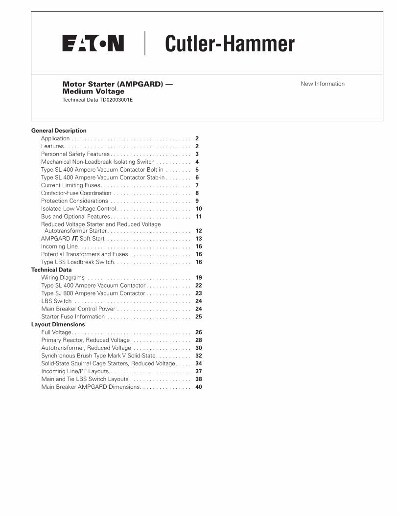
Motor Starter (AMPGARD) — Medium Voltage
Technical Data TD02003001E
New Information
General Description
Application . . . . . . . . . . . . . . . . . . . . . . . . . . . . . . . . . . . . .
2
Features . . . . . . . . . . . . . . . . . . . . . . . . . . . . . . . . . . . . . . .
2
Personnel Safety Features . . . . . . . . . . . . . . . . . . . . . . . . .
3
Mechanical Non-Loadbreak Isolating Switch . . . . . . . . . . .
4
Type SL 400 Ampere Vacuum Contactor Bolt-in . . . . . . . .
5
Type SL 400 Ampere Vacuum Contactor Stab-in . . . . . . . .
6
Current Limiting Fuses. . . . . . . . . . . . . . . . . . . . . . . . . . . .
7
Contactor-Fuse Coordination . . . . . . . . . . . . . . . . . . . . . . . .
8
Protection Considerations . . . . . . . . . . . . . . . . . . . . . . . . .
9
Isolated Low Voltage Control . . . . . . . . . . . . . . . . . . . . . . .
10
Bus and Optional Features. . . . . . . . . . . . . . . . . . . . . . . . .
11
Reduced Voltage Starter and Reduced VoltageAutotransformer Starter . . . . . . . . . . . . . . . . . . . . . . . . . .
12
AMPGARD
IT.
Soft Start . . . . . . . . . . . . . . . . . . . . . . . . . .
13
Incoming Line. . . . . . . . . . . . . . . . . . . . . . . . . . . . . . . . . . .
16
Potential Transformers and Fuses . . . . . . . . . . . . . . . . . . .
16
Type LBS Loadbreak Switch. . . . . . . . . . . . . . . . . . . . . . . .
16
Technical Data
Wiring Diagrams . . . . . . . . . . . . . . . . . . . . . . . . . . . . . . . .
19
Type SL 400 Ampere Vacuum Contactor . . . . . . . . . . . . . .
22
Type SJ 800 Ampere Vacuum Contactor . . . . . . . . . . . . . .
23
LBS Switch . . . . . . . . . . . . . . . . . . . . . . . . . . . . . . . . . . . .
24
Main Breaker Control Power . . . . . . . . . . . . . . . . . . . . . . .
24
Starter Fuse Information . . . . . . . . . . . . . . . . . . . . . . . . . .
25
Layout Dimensions
Full Voltage. . . . . . . . . . . . . . . . . . . . . . . . . . . . . . . . . . . . .
26
Primary Reactor, Reduced Voltage. . . . . . . . . . . . . . . . . . .
28
Autotransformer, Reduced Voltage . . . . . . . . . . . . . . . . . .
30
Synchronous Brush Type Mark
V
Solid-State. . . . . . . . . . .
32
Solid-State Squirrel Cage Starters, Reduced Voltage. . . . .
34
Incoming Line/PT Layouts . . . . . . . . . . . . . . . . . . . . . . . . .
37
Main and Tie LBS Switch Layouts . . . . . . . . . . . . . . . . . . .
38
Main Breaker AMPGARD Dimensions. . . . . . . . . . . . . . . .
40

2 EATON CORPORATION Cutler-Hammer
Motor Starter (AMPGARD) Technical Data TD02003001E Effective: December 2005
General Description
Application
The Cutler-Hammer
�
AMPGARD
�
medium voltage metal-enclosed control family from Eaton’s electrical business provides control and protection of medium voltage motors and equipment rated 2300 to 6600 volts nominal/7200 volts maximum.
AMPGARD control has a complete metal-enclosed offering:
●
Full and reduced voltage starting of medium voltage motors up to 8000 hp.
●
Main breaker metal-enclosed switchgear, a smaller footprint, single integrated assembly direct coupled to the AMPGARD control.
●
Integral LBS load break available as main, tie or feeder. The LBS can be supplied as fused or un-fused.
Features
Personnel safety
: Positive mechanical isolating switch with visi-ble disconnect completely grounds and isolates the starter from the line connectors with a mechanically driven isolating shutter, leaving no exposed high voltage. Medium voltage door is mechan-ically locked closed with the disconnect; low voltage section has separate door and is segregated from the medium voltage section.
Ease of installation:
Current limiting fuses, contactor assembly and isolating switch assembly are easily removed from the enclosure; line and load terminals are completely accessible from the front.
Ease of maintenance:
All components are front accessible, facilitating routine inspection and/or parts replacement. The low voltage compartment is painted white as standard to maximize serviceability.
Simplicity of design:
Component-to-component design eliminates half of the electrical connections.
Time-proven contactor technology: Two vacuum contactor ratings are utilized, 400 ampere and 800 ampere. 400 ampere contactors are available as stab-in or bolt-in design. 800 ampere contactors are available as stab-in design only.
High degree of isolation:
Main bus is located in separate com-partment on top of lineup. Vertical bus is barriered in rear of starter and auxiliary compartments. Load cables are isolated from adja-cent starter in two-high sections. A vertical low voltage wireway is provided for isolation of customer control wiring. The low voltage control compartment is isolated from medium voltage by steel barriers.
AMPGARD Motor Control Assembly
Starter catalog types are available for the following applications:
●
Squirrel cage, full voltage (reversing and non-reversing).
●
Squirrel cage, primary reactor.
●
Squirrel cage, autotransformer.
●
Reduced voltage solid-state.
●
Synchronous full voltage.
●
Synchronous primary reactor.
●
Synchronous auto-transformer (reversing and non-reversing).

EATON CORPORATION Cutler-Hammer
Motor Starter (AMPGARD) Technical Data TD02003001E
©
Copyright 2005
3
Personnel Safety Features
One of the most important considerations in designing the Cutler-Hammer AMPGARD starter was personnel safety. The result is an extensive system of interlocks and other safety features.
Interlocks
Interlocking on AMPGARD starters includes:
●
Isolating switch mechanism locks the medium voltage door closed when the switch is in the ON position.
●
Provision for optional key interlocks.
●
When door is open, interlock prevents operating handle from being moved inadvertently to ON position.
●
When contactor is energized, isolating switch cannot be opened or closed.
Other Safety Features
AMPGARD starters include many additional features designed to protect operating personnel. These features include:
●
Provision for a padlock on the isolating switch handle in OFF position.
●
Shutter barrier between line terminals and isolation switch stabs is mechanically driven.
●
Distinctive marking on back of switch assembly appears when shutter barrier is in position and starter is completely isolated from the line.
●
Grounding clips provide a positive grounding of the starter and main fuses when the isolating switch is opened.
●
High and low voltage circuits are compartmentalized and isolated from each other.
●
The drawout isolation switch is easily removed by loosening two bolts in the back of the switch. The shutter remains in place when the switch is withdrawn.
Isolation Switch Handle
Shutter Mechanism and Finger Barrier Isolation of Incoming Line Bus (Shown with Removable Portion of Isolation Switch Removed)
Isolation SwitchOperating Shaft
Isolation Switch Door Locking Mechanism
Mechanical Interlock with Contactor
Removable Cover Allows Access to Bolted Line Side Connections
Shutter Operated by Stab Motion when Isolation Switch is in Position
Distinctive Marking when Shutter is in Closed Position
Motion of Shutter
4 EATON CORPORATION Cutler-Hammer
Motor Starter (AMPGARD) Technical Data TD02003001E Effective: December 2005
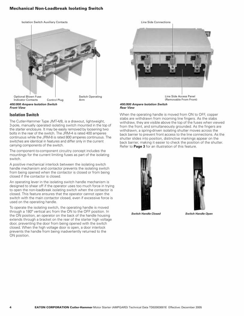
Mechanical Non-Loadbreak Isolating Switch
400/800 Ampere Isolation Switch 400/800 Ampere Isolation Switch Front View Rear View
Isolation Switch
The Cutler-Hammer Type JMT-4/8, is a drawout, lightweight, 3-pole, manually operated isolating switch mounted in the top of the starter enclosure. It may be easily removed by loosening two bolts in the rear of the switch. The JRM-4 is rated 400 amperes continuous while the JRM-8 is rated 800 amperes continuous. The switches are identical in features and differ only in the current carrying components of the switch.
The component-to-component circuitry concept includes the mountings for the current limiting fuses as part of the isolating switch.
A positive mechanical interlock between the isolating switch handle mechanism and contactor prevents the isolating switch from being opened when the contactor is closed or from being closed if the contactor is closed.
An operating lever in the isolating switch handle mechanism is designed to shear off if the operator uses too much force in trying to open the non-loadbreak isolating switch when the contactor is closed. This feature ensures that the operator cannot open the switch with the main contactor closed, even if excessive force is used on the operating handle.
To operate the isolating switch, the operating handle is moved through a 180º vertical arc from the ON to the OFF position. In the ON position, an operator on the back of the handle housing extends through a bracket on the rear of the starter high voltage door, preventing the door from being opened with the switch closed. When the high voltage door is open, a door interlock prevents the handle from being inadvertently returned to the ON position.
When the operating handle is moved from ON to OFF, copper stabs are withdrawn from incoming line fingers. As the stabs withdraw, they are visible above the top of the fuses when viewed from the front, and simultaneously grounded. As the fingers are withdrawn, a spring-driven isolating shutter moves across the back barrier to prevent front access to the line connections. As the shutter slides into position, distinctive markings appear on the back barrier, making it easier to check the position of the shutter. Refer to
Page 3
for an illustration of this feature.
Line Side Access Panel(Removable From Front)
Isolation Switch Auxiliary Contacts Line Side Connections
Optional Blown FuseIndicator Contacts
Switch Operating ArmControl Plug
Switch Handle Closed Switch Handle Open

EATON CORPORATION Cutler-Hammer
Motor Starter (AMPGARD) Technical Data TD02003001E
©
Copyright 2005
5
Type SL 400 Ampere Vacuum Contactor Bolt-in
FIGURE 1. BOLT-IN CONTACTOR REAR/SIDE VIEW
SL 400 Ampere Vacuum Contactor
Cutler-Hammer Type SL Vacuum Contactors were designed and engineered specifically for use in AMPGARD starters. They are self-supporting, compact, drawout, 3-pole, dc magnet closed contactors. To permit application matching of the starter to the motor rating, the SL Contactor is available in 400 ampere standard and high interrupting ratings.
SL Contactors are available in the standard bolt-in configuration and optional stab-in design. Either bolt-in or stab-in designs can be supplied in a two-high configuration, with a starter maximum of 400 full load amperes. The total structure rating cannot exceed 720 amperes for a combination of two starters.
Design
Cutler-Hammer Vacuum Contactors are highly versatile, low-chop contactors that have been designed to meet all applicable NEMA
�
standards and are UL
�
recognized components. The contactors accommodate mechanical interlocks which function with the starter isolation switch and with other contactors. These interlocks provide unmatched safety and service protection.
The contactors consist of a molded frame with moving armature, magnet and vacuum interrupters. The contactor is easily positioned into the starter and long-life vacuum interrupters provide many operations with a minimal maintenance program. The SL operating coils are energized by a control board which provides a pulse-width-modulated dc output. Control voltages and contactor dropout times are programmed using a DIP switch located on the control board. The control board is mounted in a protected cavity in the molded contactor frame to prevent inadvertent access to the voltage and dropout DIP switch. Four auxiliary contacts (2NO, 2NC) are supplied with each contactor and are wired to terminal blocks on the starter control panel.
The vacuum interrupters employ special main contact materials that exhibit a low chop current plus other specially engineered characteris-tics that minimize switching surges. Surge protection is therefore not required due to the use of the vacuum contactor. Surge protection may be required for other reasons such as the high probability of lightning strike, etc.
Maintenance
Reduced maintenance is one of the outstanding features of the Cutler-Hammer Vacuum Contactor line. The special contact material in the vacuum interrupters provides long life even under severe operating conditions. The main coils operate with a very low temperature rise to maximize insulation life. Steel bearings on the main shaft provide long, trouble-free operation.
A simple go/no-go gauge is used for checking contact wear. Wear can be checked without removing the contactor from the starter. The vacuum contactor is much lighter than previous generation air-break or vacuum contactors, which allows for easier insertion and removal from the starter structure.
Contactor Control Board
DIP Switch on Contactor Control Board

6 EATON CORPORATION Cutler-Hammer
Motor Starter (AMPGARD) Technical Data TD02003001E Effective: December 2005
Type SL 400 Ampere Vacuum Contactor Stab-in with Wheels, and Line and Load Fingers
400 Ampere Stab-in Contactor
400 Ampere Bolt-in
The bolt-in version of the Cutler-Hammer SL Contactor is supplied as standard for those applications requiring a 400 ampere contac-tor. The contactor is mounted on wheels and rolls into the AMPGARD structure on steel rails. Bolted bus bars connect the contactor line and load terminals to the power components in the starter cell. A 3-phase current transformer, 3-phase potential trans-former and ground fault current transformer are mounted in the cell when required. A plug on the side of the contactor connects the contactor to the low voltage control panel.
The contactor is easily removed from the structure by removing the six bolts securing the contactor line and load terminals, and the pin connecting the isolating switch interlock arm. The contactor can be removed from the starter without disconnecting any medium voltage cables.
400 Ampere Stab-in
A stab-in version of the SL Contactor is an available option. The stab-in contactor is mounted on wheels and rolls into the AMPGARD structure. Contactor line and load fingers engage cell- mounted stabs as the contactor is inserted into the starter cell. The contactor is held in position by a bolt and bracket combination. It can be easily withdrawn from the starter cell by removing the bolt holding the contactor against the bracket and disconnecting the isolation switch interlock. The contactor can be removed from the starter without disconnecting any medium voltage cables.
800 Ampere Vacuum Contactors
The 800 ampere SL Contactor is available in a one-high configuration and is rated at 720 amperes enclosed. The 800 ampere contactor is available with a stab-in type connection only. The 800 ampere contactor is mounted on wheels and has similar features to the stab-in 400 ampere contactor.
FIGURE 2. STAB-IN CONTACTOR MECHANICAL INTERLOCK
800 Ampere Vacuum Break Contactor 7200 Volt MaximumStab-in with Wheels, and Line and Load Fingers
Mechanical Interlock with Isolation Switch
RolloutWheels
Self-Aligning Contactor Line and Load Fingers
EATON CORPORATION Cutler-Hammer
Motor Starter (AMPGARD) Technical Data TD02003001E
©
Copyright 2005
7
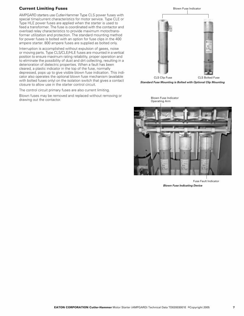
Current Limiting Fuses
AMPGARD starters use Cutler-Hammer Type CLS power fuses with special time/current characteristics for motor service. Type CLE or Type HLE power fuses are applied when the starter is used to feed a transformer. The fuse is coordinated with the contactor and overload relay characteristics to provide maximum motor/trans-former utilization and protection. The standard mounting method for power fuses is bolted with an option for fuse clips in the 400 ampere starter. 800 ampere fuses are supplied as bolted only.
Interruption is accomplished without expulsion of gases, noise or moving parts. Type CLS/CLE/HLE fuses are mounted in a vertical position to ensure maximum rating reliability, proper operation and to eliminate the possibility of dust and dirt collecting, resulting in a deterioration of dielectric properties. When a fault has been cleared, a plastic indicator in the top of the fuse, normally depressed, pops up to give visible blown fuse indication. This indi-cator also operates the optional blown fuse mechanism (available with bolted fuses only) on the isolation switch that gives a contact closure to allow use in the starter control circuit.
The control circuit primary fuses are also current limiting.
Blown fuses may be removed and replaced without removing or drawing out the contactor.
Blown Fuse Indicator
CLS Clip Fuse CLS Bolted Fuse
Blown Fuse Indicator Operating Arm
Fuse Fault Indicator
Blown Fuse Indicating Device
Standard Fuse Mounting is Bolted with Optional Clip Mounting

8 EATON CORPORATION Cutler-Hammer
Motor Starter (AMPGARD) Technical Data TD02003001E Effective: December 2005
Contactor-Fuse Coordination
The AMGARD starter provides ensured coordination between its fuses, contactor, current transformers, protective relays, and the motor it is controlling.
One of the most critical coordination issues is between the contactor and the starter fuses. The fuses must interrupt faults greater than the interrupting rating of the contactor. The AMPGARD 400 ampere high interrupting contactor (SL400A-HI) has an 8-cycle dropout time factory setting as stan-dard and will interrupt at 8500 amperes. The maximum size fuse used with an SL400A-HI contactor is a 450-24R. By comparing the fuse curve with the contactor rating, it can be observed that for faults greater than 8500 amperes, the fuse will open before the contactor. With faults less than 8500 amperes, the contactor may clear the fault before the fuse blows, depending on the settings of the protective relays. Refer to
Figure 3
for an illustration of AMPGARD coordination.
Other vacuum contactors available today may have lower inter-rupting ratings than the AMPGARD Type SL vacuum contactors. Dropout times also vary, and may be as short as two cycles on other starter designs. Lower interrupting ratings and shorter drop-out times can result in fault current levels where the contactor may be required to interrupt a fault greater than its rating. This can result in equipment failure. Refer to
Figure 4
for an illustration of an improperly coordinated starter.
AMPGARD starters also ensure coordination between other starter components. The current transformers and protective relays are selected to work properly with each other, and to protect the motor. Protective relays like the Cutler-Hammer MP-3000 provide optimal motor protection, while also rapidly opening the contactor during fault conditions. This rapid opening signal cannot open the contactor in less than its set dropout time, but it will take the motor off-line in the shortest possible time. This will help minimize mechanical damage to the motor and may prevent the starter fuses from blowing by allowing the contactor to clear the fault (only if the fault is less than the contactor interrupting rating).
AMPGARD starters utilize 400 ampere standard interrupting con-tactors (SL400-SI) when the contactor is not required to coordinate with the starter main fuse. An example of this application is the run contactor of a reduced voltage starter.
FIGURE 3. PROPER CONTACTOR FUSE COORDINATION FOUND IN AMPGARD STARTER
FIGURE 4. CONTACTOR FUSES THAT ARE NOT PROPERLY COORDINATED
ContactorInterrupting Rating
24R FuseCurve
ContactorDropout
Current
Tim
e
ContactorInterrupting Rating
24R FuseCurve
ContactorDropout
Current
Tim
e
Fault Current Rangewhere Contactor canAttempt to Open on a FaultGreater than its Rating

EATON CORPORATION Cutler-Hammer
Motor Starter (AMPGARD) Technical Data TD02003001E
©
Copyright 2005
9
Protection Considerations
Coordinated with the motor’s characteristics, the protective devices in the Cutler-Hammer AMPGARD starter provide motor protection from overload to full system capacity faults.
AMPGARD starters are supplied with an adjustable thermal over-load relay as standard. The overload relay is designed to protect the motor from sustained overloads. A Cutler-Hammer Ground-Gard relay is an available option for protection from ground faults. The factory setting for the GroundGard will initiate a starter trip at approximately 7 amperes ground current.
Multi-function solid-state motor protection relays are a common option on AMPGARD starters. The Cutler-Hammer MP-3000 is typically provided when a multi-function relay is specified. The MP-3000 provides many types of protection including overload, locked rotor, ground fault and phase loss/phase unbalance. The MP-3000 also provides start control logic to protect the motor against excessive starting. The relay may be applied to either across-the-line or reduced voltage starters. On reduced voltage starters, the MP-3000 can control the transition from reduced to full voltage, offering the greatest protection for the motor and starter. An optional RTD module can be supplied for motors with built-in RTDs.
MP-3000 Motor Protective Relay
InsulGard relays are an available option on AMPGARD starters. The InsulGard provides early warning of increasing partial dis-charge levels in the starting equipment, cables and motor. This early warning will help the user to better schedule maintenance and avoid unplanned downtime.
FIGURE 5. FULL RANGE COORDINATED PROTECTION BETWEEN CURRENT LIMITING TYPE CLS FUSES, VACUUM CONTACTOR AND MOTOR PROTECTION RELAY
Ultimate Trip
MP-3000 Motor ProtectionCurve Programmed toFollow Specific MotorDamage Curve – ProvidingMaximum MotorUtilization
Controller MaximumInterrupting Rating
InstantaneousOvercurrent
Full Load Amps
Motor Starting Curve
24R Fuse
Contactor Dropout
AsymmetricalOffset Compensation
Contactor InterruptingCapacity
Current
Tim
e In
Sec
on
ds

10 EATON CORPORATION Cutler-Hammer
Motor Starter (AMPGARD) Technical Data TD02003001E Effective: December 2005
Isolated Low Voltage Control
The low voltage door has four cutouts as standard.
AMPGARD 400 Ampere Starter Door Closed
View of Isolation Switch Through Viewing Window
The Device Panel, MP-3000 and DP-4000 all fit in this same size low voltage door cutout. The low voltage control panel is behind the low voltage door and is completely isolated from the medium voltage compartment. A standard viewing window allows visual verification of the isolation switch status before attempting to open the medium voltage door. The medium voltage door is locked closed whenever the isolation switch is closed.
AMPGARD 400 Ampere Starter — Low Voltage Door Open
AMPGARD 400 Ampere Starter –— Medium Voltage Door Open
Low Voltage Access Door
Digital Meter(When Specified)
Indicating LightsStart/Stop Pushbutton (When Specified)
1/4 Turn Door LatchTop and Bottom
MP-3000 (When Specified)
Distinctive Markings on Isolation Switch Shutter Indicate Shutter is Closed and Switch is Open
Standard Isolation Switch Viewing Window
Isolation Switch Operating Handle (Mechanism Locks Medium Voltage Door When Switch is Closed)
Medium Voltage Access Door
Predrilled Holes for AdditionalControl Devices
Interposing Control RelayDIN-Rail Mounted
Standard Isolation Switch Viewing Window
Vertical Wireway
Bolted Main Fuses
Customer Terminal Blocks for Remote Control Connec-tions
Horizontal Wireway
Motor Load Connec-tions (Accepts 2-Hole Lugs as Standard)
Control Power Transformer (750 VA Standard, up to 4 kVA Available)

EATON CORPORATION Cutler-Hammer
Motor Starter (AMPGARD) Technical Data TD02003001E
©
Copyright 2005
11
Bus and Optional Features
Bus Compartment Top View 3000 A Main Horizontal Bus
Main Bus
When starters are grouped together in a lineup, a typical option is the main bus. The Cutler-Hammer AMPGARD main bus is mounted in its own 12-inch (305 mm) high enclosure, which isolates it from the starter. The connection from the main bus to the starter is done with rigid vertical bus. Insulated barriers are provided for separate top entry of power and control cables. The main bus is top, side and front accessible, which allows for ease of maintenance or extension of lineup without disassembling the starters.
Main bus is available for 1000, 1200, 2000 and 3000 amperes. Main bus is uninsulated as standard. Fully insulated bus is an available option. Bus may be supplied with either tin or silver plat-ing. Crossover bus, busway entry, and pull boxes are not available for the 3000 ampere design (3000 ampere bus duct provisions are available with the Main Breaker AMPGARD, see
Page 17
).
The standard bus short circuit rating is per NEMA standards and is based on the let-through current of the largest fuse used in any starter. An optional 50 kA, 1-second bus rating is available for customers that require a higher rating for the main bus.
Vertical Bus
Vertical bus is located behind a fixed barrier in the rear of the enclosure. It is fully insulated as standard, with plating to match that of the main bus.
UL and CSA Certification
AMPGARD starters are designed, assembled and tested to meet all applicable standards: NEMA/ANSI ICS3, EEMAC E14-1, UL 347 and CSA
�
C22.2 No. 14. The major components i.e., contactor, isolating switch, fuses, MP-3000, IQ DP-4000, and IQ Analyzer are UL recognized.
UL or CSA labeling of a specific starter requires review to ensure that all requested modifications and auxiliary devices meet the appropriate standards. Refer to factory when specified. AMPGARD starters meet the requirements of IEC standards 60694, 60298 and 60470.
Medium Voltage Conduit Area(Upper Starter)
Insulated Barriers to Separate Motor Load Cables from Main Bus
Low Voltage Conduit Area
Phase C
Bus Splice Plates
Vertical Bus Drops
Phase B
Phase A
Medium Voltage Conduit Area(Lower Starter)
Seismic Certification
AMPGARD starters are seismically tested, seismically qualified, and exceed requirements of both the International Building Code
�
(IBC) and California Building Code Title 24. Seismic certified start-ers require the use of special keyed door latches on the medium voltage doors to ensure that the doors do not open during a seismic event. No other special modifications are required.
ABS Certification
Cutler-Hammer AMPGARD Medium Voltage Control assemblies have been certified under the ABS type approval program. ABS (American Bureau of Shipping) develops and verifies standards for design, construction and operational maintenance of marine-related facilities. ABS Type Approval is a means of demonstrating compliance with specifications and recording the compliance in the ABS Web site. AMPGARD is listed in the ABS publications and Web site. AMPGARD may be used onboard a vessel, MODU (mobile offshore drilling unit) or facility classed by ABS with two conditions:
1. The AMPGARD assembly may not be used in the propulsion system.
2. The AMPGARD assembly may not be placed on deck.
The standard AMPGARD assembly will be modified with grab rails, drip shields, insulated bus, and wind latches for the doors to meet all the ABS requirements.
Other Optional Features
AMPGARD starters are available with a variety of accessories and modifications to satisfy a wide range of application requirements. Some of the broad areas covered include:
●
Bus and cable entrance enclosures.
●
Transformers.
●
Power factor correction capacitors.
●
Operators and pilot devices.
●
Instruments and meters.
●
Control relays and timers.
●
Solid-state or selected electromechanical protection devices.
1000 and 1200 A Bus Arrangement
Vertical Bus, Rear View (2-High 400 A)

12 EATON CORPORATION Cutler-Hammer
Motor Starter (AMPGARD) Technical Data TD02003001E Effective: December 2005
Reduced Voltage Starters
Eaton offers traditional electromechanical reduced voltage starters in addition to the AMPGARD IT. solid-state starter. Unless other-wise specified, reactors and autotransformers are NEMA medium duty rated. They are designed for three 30-second starters per hour. Heavy-duty reactors and transformers can be supplied when specified. Locked rotor current must be specified when ordering reduced voltage starters to ensure that the reactors or autotrans-formers are properly sized.
Reduced Voltage Reactor Starter
TABLE 1. TYPE 502 REACTOR STARTING CHARACTERISTICS
� Factory set on 65% tap.
Reactor Starter
Advantages
● Reduces starting currents.● Least costly reduced voltage starting method.
Disadvantages
● Large footprint: 1-1/2 structures at 400 amperes.● “Bump” on transition to full voltage.● Not as efficient as autotransformer.● Due to reduced torque during starting, motor must
typically be unloaded during the start sequence.
Sequence of Operation
● Main contactor (M) closes.● Current flows through reactor reducing voltage to motor
(based on tap setting).● When motor current reaches ~125%, the run contactor
(R) closes providing full voltage to the motor.
Reduced Voltage Autotransformer StarterTABLE 2. TYPE 602 AUTO-TRANSFORMER STARTING CHARACTERISTICS
� Factory set on 65% tap.
Auto Transformer Starter
Advantages
● Produces the most torque per incoming line ampere of any reduced voltage starting method.
● Less costly than RVSS.
Disadvantages
● Large footprint: 1-1/2 structures at 400 amperes.● More costly than reactor.● “Bump” on transition to full voltage.● Due to reduced torque during starting, motor must
typically be unloaded during the start sequence.
Sequence of Operation
● Shorting contactor (S) closes.● Main contactor (M) closes.● Current flows through autotransformer reducing voltage to
motor (based on tap setting).● When motor current reaches ~125%, the shorting contactor (S)
opens and the run contactor (R) closes providing full voltage to the motor.
Note: Since the motor is never disconnected from the supply voltage, the starting is closed transition.
StarterType
%Motor Voltage
%Motor Current
% Line Current % Torque
80% Tap65% Tap �50% Tap
806550
806550
806550
644225
StarterType
%Motor Voltage
%Motor Current
% Line Current % Torque
80% Tap65% Tap �50% Tap
806550
806550
674528
644225

EATON CORPORATION Cutler-Hammer Motor Starter (AMPGARD) Technical Data TD02003001E ©Copyright 2005 13
AMPGARD IT. Soft Start
The 400 ampere AMPGARD IT. Soft Start requires one full height structure with a full voltage starter in the upper compartment bus connected to a soft start truck assembly in the lower compart-ment. The soft starter includes internal fault protection and built-in basic motor protection. The standard assembly includes an MP-3000 motor relay for advanced motor protection.
Why is Soft Starting Desirable?
● Eliminate shock to your mechanical components.● Avoid coupling and shaft damage.● Prevent rotor and winding failure.● Stop drive belt squeal and breakage.● Prevent water hammer in pipes.● Soft stop the pump motors.● Reduce pressure so valves close gently.● Avoid the surge wave.● Reduce peak starting currents.● Reduce voltage drop on motor start.
Ratings
● 2300 – 4800 Vac grounded systems.● 60 kV BIL impulse rating.● Continuous current: to 400 amperes.
The AMPGARD IT. Soft Start is recommended for application only on power systems that are solidly grounded or resistance grounded. Ungrounded systems are not recommended.
Industry Standards
The AMPGARD IT. Soft Start is designed and built to meet all applicable industry standards including UL listing as a complete assembly.● NEMA ICS3 – 1993● UL 347● CSA● EEMAC E14-1● Manufactured in an ISO� 9001 and ISO 14001 certified facility
Starting Characteristics
The soft start controller provides a number of selectable starting characteristics as standard:
Kick Start
Provides an initial boost of current to overcome motor and system inertia.
Ramp Start
Operator sets the initial starting torque value then raises the torque to full voltage.
Current Limit
Limits the maximum starting current. Used in long start time applications and motor protection applications.
Soft Stop
Provides extended coast to rest time. Used in high friction load applications where a sudden stop may cause system damage.
An optional pump control algorithm provides a special S shaped torque curve that can eliminate water hammer in hydraulic systems.
AMPGARD IT. Soft Start
Full VoltageStarter Cubicle
MP-3000 Relay
Soft Start LV Control Compartment
DrawoutSCR Truck(Located Behind MV Door)
14 EATON CORPORATION Cutler-Hammer Motor Starter (AMPGARD) Technical Data TD02003001E Effective: December 2005
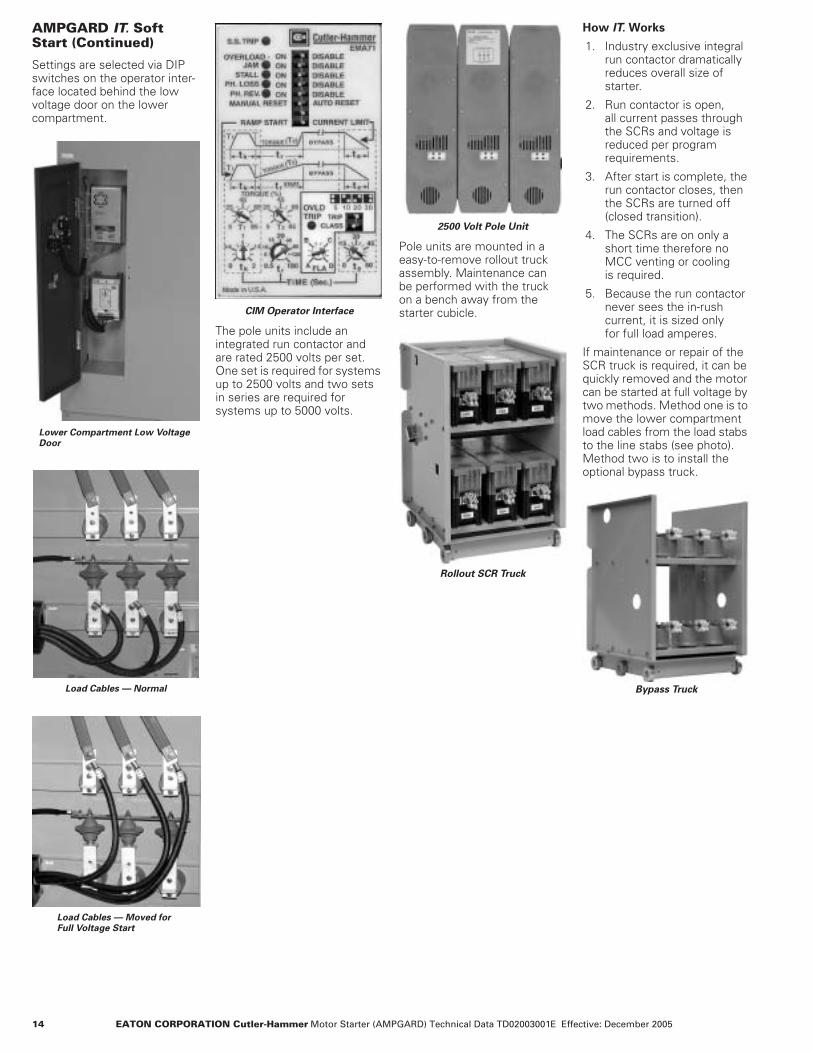
AMPGARD IT. Soft Start (Continued)
Settings are selected via DIP switches on the operator inter-face located behind the low voltage door on the lower compartment.
Lower Compartment Low Voltage Door
Load Cables — Normal
Load Cables — Moved for Full Voltage Start
CIM Operator Interface
The pole units include an integrated run contactor and are rated 2500 volts per set. One set is required for systems up to 2500 volts and two sets in series are required for systems up to 5000 volts.
2500 Volt Pole Unit
Pole units are mounted in a easy-to-remove rollout truck assembly. Maintenance can be performed with the truck on a bench away from the starter cubicle.
Rollout SCR Truck
How IT. Works
1. Industry exclusive integral run contactor dramatically reduces overall size of starter.
2. Run contactor is open, all current passes through the SCRs and voltage is reduced per program requirements.
3. After start is complete, the run contactor closes, then the SCRs are turned off (closed transition).
4. The SCRs are on only a short time therefore no MCC venting or cooling is required.
5. Because the run contactor never sees the in-rush current, it is sized only for full load amperes.
If maintenance or repair of the SCR truck is required, it can be quickly removed and the motor can be started at full voltage by two methods. Method one is to move the lower compartment load cables from the load stabs to the line stabs (see photo). Method two is to install the optional bypass truck.
Bypass Truck

EATON CORPORATION Cutler-Hammer Motor Starter (AMPGARD) Technical Data TD02003001E ©Copyright 2005 15
Synchronous Motor, Brush Type Solid-State Soft Sync Field Control
The synchronous motor starter includes the basic induction motor control in the bottom half of the structure. The synchronous con-trol and protection function fit easily in the upper compartment.
The step down static excitation transformer is connected to the load side of the main contactor and is protected by its own current-limiting fuses.
The static exciter is an SCR type. Its dc voltage output is adjust-able via door-mounted potentiometer. Minimum setting is 50% of rated voltage.
The synchronous control board monitors the induced field during acceleration and energizes the dc rotor field at the optimum speed and rotor-stator pole relationship.
Solid-state, brush-type synchronous motor control includes the following protective features:● Locked rotor protection.● Incomplete sequence.● Failure to synchronize.● Fuse failure.● Pullout protection.● Field loss protection.
The motor windings are protected by the conventional induction motor control protection (thermal, MP-3000).
When ordering you must specify:● dc field amperes.● dc field volts.● Maximum induced field current rms at start (starting and
discharge resistor amperes).● Starting and discharge resistor ohms.
Note: Maximum induced field current multiplied by starting and discharge resistor ohms must be less than 1500 volts to prevent damage to starting equipment and motor.
Synchronous Motor, Brushless ECS/VR Field Controller
The brushless synchronous motor starter includes the basic induc-tion motor control in the bottom half of the structure. The ECS/VR synchronous control and protection module fits easily into the upper compartment.
The step down excitation transformer is connected to the load side of the main contactor and is protected by its own current-limiting fuses.
The ECS/VR uses IGBT technology to control the dc output. The field voltage level can be adjusted from the HMI. The output is adjustable across the full range 0 – 150 Vdc.
The ECS/VR applies field voltage after an adjustable time delay. The controller monitors the stator current and voltage levels for metering and protection purposes. Automatic power factor regulation is an available option.
The ECS/VR brushless motor control includes the following protective features:● Incomplete sequence.● Failure to synchronize.● Pullout protection.● Field loss protection.● Over excitation.
The motor windings are protected by a motor protection relay such as the MP-3000.
When ordering you must specify:● dc field amperes.● dc field voltage.● Complete motor data sheet is preferred.
Brushless ECS/VR Field Controller
16 EATON CORPORATION Cutler-Hammer Motor Starter (AMPGARD) Technical Data TD02003001E Effective: December 2005
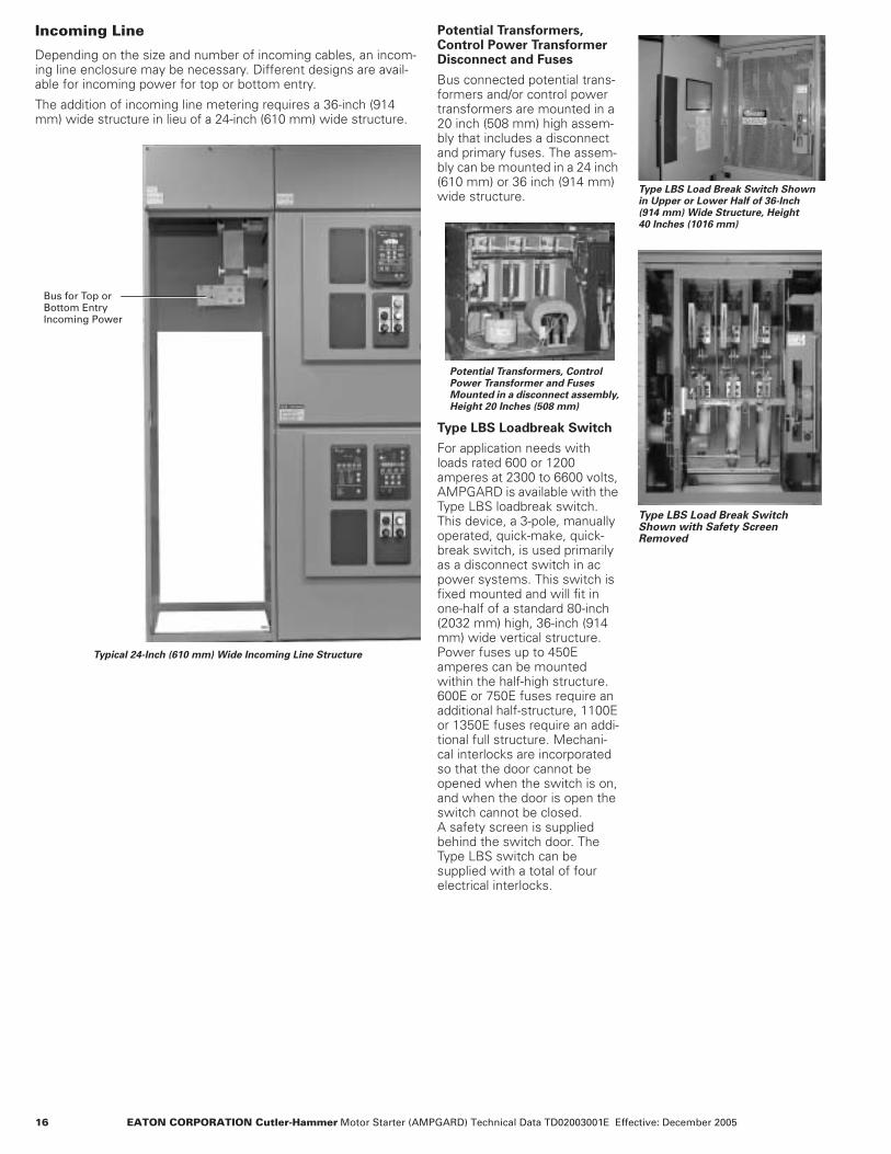
Incoming Line
Depending on the size and number of incoming cables, an incom-ing line enclosure may be necessary. Different designs are avail-able for incoming power for top or bottom entry.
The addition of incoming line metering requires a 36-inch (914 mm) wide structure in lieu of a 24-inch (610 mm) wide structure.
Typical 24-Inch (610 mm) Wide Incoming Line Structure
Bus for Top or Bottom Entry Incoming Power
Potential Transformers, Control Power Transformer Disconnect and Fuses
Bus connected potential trans-formers and/or control power transformers are mounted in a 20 inch (508 mm) high assem-bly that includes a disconnect and primary fuses. The assem-bly can be mounted in a 24 inch (610 mm) or 36 inch (914 mm) wide structure.
Potential Transformers, Control Power Transformer and Fuses Mounted in a disconnect assembly, Height 20 Inches (508 mm)
Type LBS Loadbreak Switch
For application needs with loads rated 600 or 1200 amperes at 2300 to 6600 volts, AMPGARD is available with the Type LBS loadbreak switch. This device, a 3-pole, manually operated, quick-make, quick-break switch, is used primarily as a disconnect switch in ac power systems. This switch is fixed mounted and will fit in one-half of a standard 80-inch (2032 mm) high, 36-inch (914 mm) wide vertical structure. Power fuses up to 450E amperes can be mounted within the half-high structure. 600E or 750E fuses require an additional half-structure, 1100E or 1350E fuses require an addi-tional full structure. Mechani-cal interlocks are incorporated so that the door cannot be opened when the switch is on, and when the door is open the switch cannot be closed. A safety screen is supplied behind the switch door. The Type LBS switch can be supplied with a total of four electrical interlocks.
Type LBS Load Break Switch Shown in Upper or Lower Half of 36-Inch (914 mm) Wide Structure, Height 40 Inches (1016 mm)
Type LBS Load Break Switch Shown with Safety Screen Removed
EATON CORPORATION Cutler-Hammer Motor Starter (AMPGARD) Technical Data TD02003001E ©Copyright 2005 17
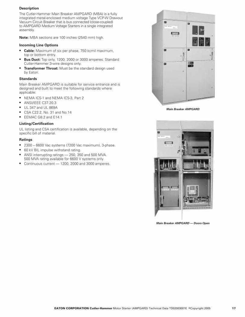
Description
The Cutler-Hammer Main Breaker AMPGARD (MBA) is a fully integrated metal-enclosed medium voltage Type VCP-W Drawout Vacuum Circuit Breaker that is bus connected (close-coupled) to AMPGARD Medium Voltage Starters in a single integrated assembly.
Note: MBA sections are 100 inches (2540 mm) high.
Incoming Line Options
● Cable: Maximum of six per phase, 750 kcmil maximum, top or bottom entry.
● Bus Duct: Top only, 1200, 2000 or 3000 amperes. Standard Cutler-Hammer 3-wire designs only.
● Transformer Throat: Must be the standard design used by Eaton.
Standards
Main Breaker AMPGARD is suitable for service entrance and is designed and built to meet the following standards where applicable:● NEMA ICS-1 and NEMA ICS-3, Part 2● ANSI/IEEE C37.20.3● UL 347 and UL 869A● CSA C22.2, No. 31 and No.14● EEMAC G8.2 and E14.1
Listing/Certification
UL listing and CSA certification is available, depending on the specific bill of material.
Ratings
● 2300 – 6600 Vac systems (7200 Vac maximum), 3-phase.● 60 kV BIL impulse withstand rating.● ANSI interrupting ratings — 250, 350 and 500 MVA.
500 MVA rating available for 6600 V systems only.● Continuous current — 1200, 2000 and 3000 amperes.
Main Breaker AMPGARD
Main Breaker AMPGARD — Doors Open

18 EATON CORPORATION Cutler-Hammer Motor Starter (AMPGARD) Technical Data TD02003001E Effective: December 2005
Requires Less Floor Space
● Only 60 inches (1524 mm) deep, the integrated MBA design provides a bus system that directly connects to AMPGARD motor starters, eliminating space-consuming transition sections. The reduced floor space requirements yield significant cost savings, particularly when installation in a prefabricated electrical house is required.
● Back-to-back design provides for an increase in the number of starters without an increase in floor space.
Front/Side Accessible Connections
● All connections requiring maintenance are front or side accessible.
● Rear access space is not required.● An MBA (excluding back-to-back design) can be installed flush
against the wall.
Circuit Breaker Rating Chart
TABLE 3. ANSI STANDARDS — TYPE VCP-W CIRCUIT BREAKERS RATED ON SYMMETRICAL CURRENT RATING BASIS
Microprocessor-Based Devices
Cutler-Hammer FP-5000 and Digitrip� 3000 Overcurrent Protective Relays provide programmable circuit protection, information and operator conducted testing.
Metering
● IQ DP-4000 meter.● IQ Analyzer meter.
Communications
Cutler-Hammer PowerNet� communications provides for monitor-ing and controlling complete electrical distribution systems of those parts of a system selected by the operator.
Enclosures
The MBA is available in NEMA/EEMAC 1, NEMA/EEMAC 1G/1A, and NEMA/EEMAC 12 enclosures.
Seismic Qualified
The Main Breaker AMPGARD is seismically tested, seismically qualified, and exceeds requirements of the International Building Code (IBC) and the California Building Code (CBC).
AMPGARD 2-High Structure Bus Connected to Main Breaker Section
Low Voltage Equipment Cell Compartment for Metering and Protection Devices
Side Panel Removed to Show IncomingCable Connections
ANSIInterruptingRating
MVA
NominalVoltageClass
kV
ImpulseWithstandRating
kV Peak
Short CircuitCurrentat Rated Maximum kVkA rms
ContinuousCurrentat 60 Hz
Amperes
250 4.16 60 kV BIL 29 at 4760 V 120020003000
350 4.16 60 kV BIL 41at 4760 V 120020003000
500 7.2 60 kV BIL 33 at 8250 V 120020003000
EATON CORPORATION Cutler-Hammer Motor Starter (AMPGARD) Technical Data TD02003001E ©Copyright 2005 19
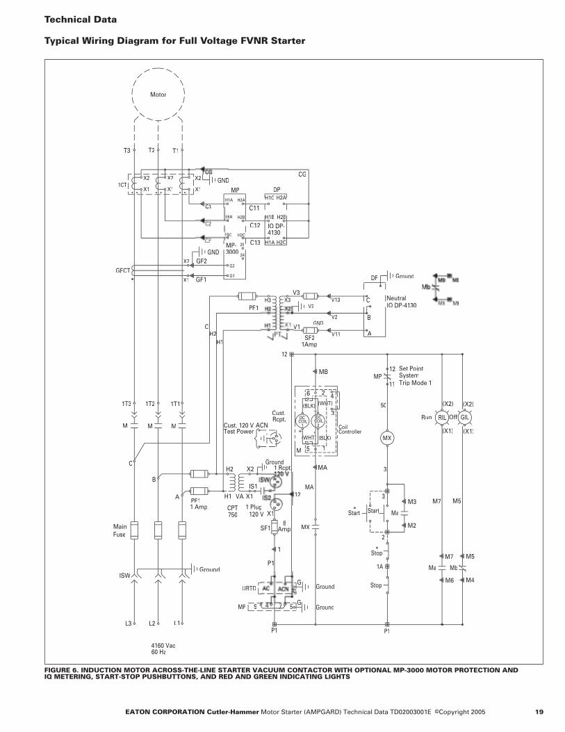
Technical Data
Typical Wiring Diagram for Full Voltage FVNR Starter
FIGURE 6. INDUCTION MOTOR ACROSS-THE-LINE STARTER VACUUM CONTACTOR WITH OPTIONAL MP-3000 MOTOR PROTECTION AND IQ METERING, START-STOP PUSHBUTTONS, AND RED AND GREEN INDICATING LIGHTS
4160 Vac60 Hz
CH2
H1
V2
V3
PF1
GNDV2
SF21Amp
GFCT
GND
MP
GGround
MX
MP
3
50
MX
1
2
5
CoilController
4
3+
(BLK)
-
1 2COILDC
M
MA
11
Set Point SystemTrip Mode 1
MP
GGround
URTD
DP
DP
IQ DP-4130
Ground
CG
7508
*
P1
1A
Ma
Stop
Stop
StartStart
*
M7
Ma
M5
Mb
RILRun Off
8
C13
C12
M M M
1T11T21T3
L1L2
ISW
L3
Ground
MainFuse
A
B
C
X1
X2
X1
X2
X11CT
GND
C3
Motor
T1T2T3
X2
X1
59 4 77
H2C
H1C H2A
H1A
H2BH1B
IQ DP-4130
B
AAA
Neutral
X2
X1
CPT1 AmpPF1
ACNTest PowerCust. 120 V
Rcpt.Cust.
120 V1 Plug
AmpSF1
X1
12
Ground
(X2)
(X1)
(X2)
(X1)
G2
G1
MP-3000
1B
H1A H2A
H2B
1C
25
24
20 EATON CORPORATION Cutler-Hammer Motor Starter (AMPGARD) Technical Data TD02003001E Effective: December 2005
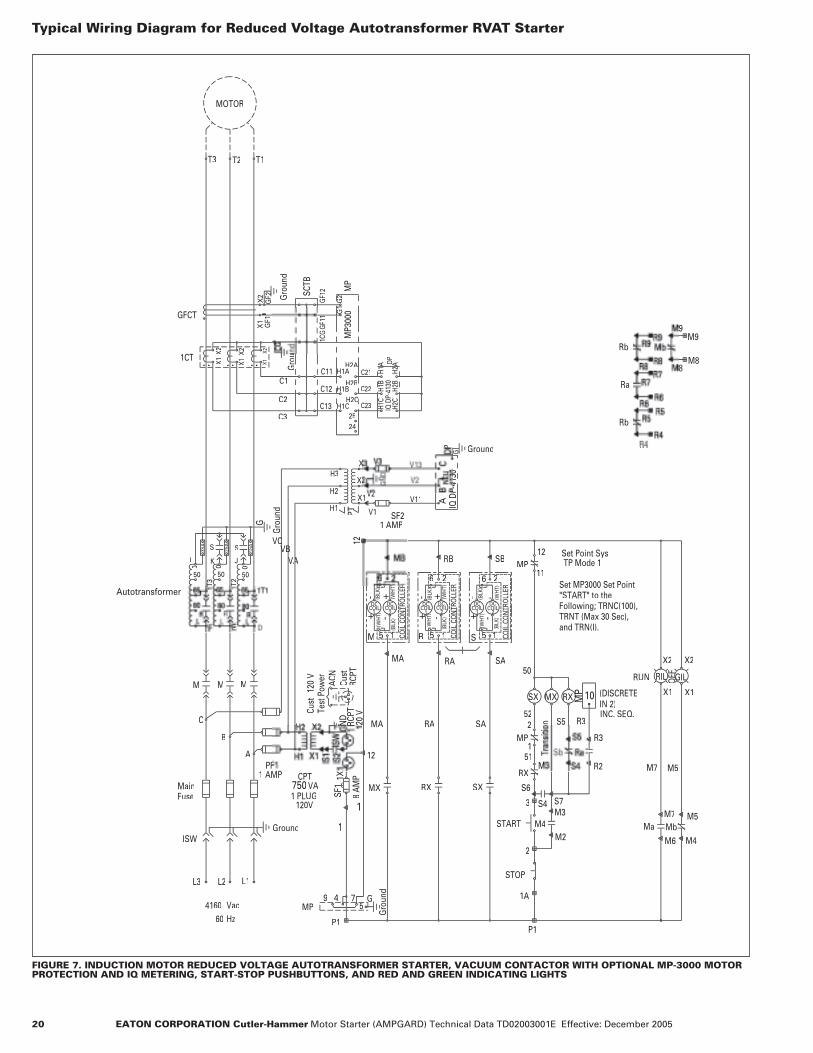
Typical Wiring Diagram for Reduced Voltage Autotransformer RVAT Starter
FIGURE 7. INDUCTION MOTOR REDUCED VOLTAGE AUTOTRANSFORMER STARTER, VACUUM CONTACTOR WITH OPTIONAL MP-3000 MOTOR PROTECTION AND IQ METERING, START-STOP PUSHBUTTONS, AND RED AND GREEN INDICATING LIGHTS
L1L2
Fuse
ISW
L3
Ground
Main
A
B
C
HzVac
604160
3SA
1SA
Gro
und
S
L
0
T2
Autotransformer
M M M
MOTOR
T1T2T3
G
Set MP3000 Set Point "START" to theFollowing; TRNC(100),TRNT (Max 30 Sec),and TRN(I).
MP
50
MP
RX
SX
R3S552
51
MP
MA RA SA
P1
RXMX
12
SX
22
R
6
5
-(B
LK)
(WH
T)+
1M
DCDC
-+
1 COIL
CO
NTR
OLL
ER
1
-
(BLK
)
5
6
SB
SA
11
Set Point SysTP Mode 1MP
CPTVA
AMP750
1
1
ACN
RCPT
Cust
Cust
1 PLUG120V
120
V
SF1
8
STOP
START M4
2
3
1A
M7 M5
M7
RUN OFF
R4Ground
PT
1 AMPSF2
V11
MP
DP
C21
C22
C23
Gro
und
C3
C2
C1
1CT
Gro
u
VC
VAVB
X2
X1
X2
X1
H3
H2
H1
X1X2 X2
X1
9 4
(DISCRETE IN 2)INC. SEQ.
G2
MP3
000
H1AH2A
H2B
H2CCH1C
2524

EATON CORPORATION Cutler-Hammer Motor Starter (AMPGARD) Technical Data TD02003001E ©Copyright 2005 21
Typical Wiring Diagram for AMPGARD IT. Soft Start
FIGURE 8. INDUCTION MOTOR REDUCED VOLTAGE SOLID-STATE STARTER, VACUUM CONTACTOR WITH MP-3000 MOTOR PROTECTION WITH OPTIONAL UNIVERSAL RTD MODULE LOCAL AND REMOTE START-STOP PUSHBUTTONS, AND LOCAL AND REMOTE RED AND GREEN INDICATING LIGHTS
CUSTOMER CONN. = TX TYPE LIGHTTX
3LA
4
7
A
P1
50
60
NOTEPROGRAMMINGSEE MP
MPRX
AUX2 RELAY
CIM
SEENOTE #2
SS T
RIP
DIS
ABL
ED
ISA
BLE
DIS
ABL
E
DIS
ABL
EPH
REV
AU
TOD
ISA
BLE
FEATURES)(SPECIALFOR S.F.NOTE #4SEE
B
HARNESS BELOW
TO T
RIP
CIRC
UIT
ABO
VE
HARNESS TOCONTROL WIRE
RVSS TRUCK ASSY
SEE NOTE #3
24V
++
-
AST
ROD
YNE
S# A
S-32
0-24
CR11
-+
3
COIL
2
MODEBYPASS
START
*
54
55
TDC
FDT
53
RESET
+ -
1
MB
12
P1
M3
G1 GND
51
52
CR
+ +
LN120VAC INPUT
CM
PS
RVSS
SUPPLY
INPUTS24VDC
RESE
T
DIS
ABL
E
4P 1 2 3
STO
P
STA
RT
MA
NU
AL
IN BYPASS
TIMEDELAY
SEE NOTE #1
MXTD
CR
MXTD
FAULT
95
CR
STOP
STOPU GND
23
CUST
CUST 120V
MP
AX2 MOD1SET POINT SYS
M GND
MA
4160 VAC60 HZ
HARNESS TO CMCONTROL WIRE
RVSS TRUCK ASSY
1T3
THEN MXTD TIME SHOULD BE SET AT .1 SEC.STOP IS DISABLED (0 SEC) ON THE RVSS CONTROL,ON THE RVSS CONTROL SETTINGS. IF SOFTTHAN THE SOFT STOP SELECTED TIME (Ts)ADJUST TIME TO BE 5 SEC GREATER SELECT TIMING RANGE ON MXTD AND
-NOTE #1
IN COMPLETELY/CORRECTLY TO RVSS TRUCK ASSY.FROM CONTROL MODULE (CM) PLUGGEDCONNECTION MADE WHEN WIRE HARNESSRVSS WIRE HARNESS SAFETY.
-NOTE #3
-NOTE #2THE S.S. TRIP LIGHT ON THE RVSS CONTROLINTERFACE MODULE IN THE RVSS CONTROLCOMPT WILL COME ON WHEN 'M' ISOPEN. THE S.S. TRIP LIGHT WILL GO OUT APPROX. 2 SEC AFTER 'M' CLOSES.
-NOTE #4S.F. ENABLE/DISABLE (SPECIAL FEATURES)WILL APPEAR ON CIM IF PUMP APPLICATIONSOFTWARE IS INSTALLED IN UNIT.
M5
P
GILOFF
4
M5
WILFAULTRVSS
58
FAX
SET @ 3 SEC.1-30 SECON
DELAY
FDT
P1
12
CON
TIN
UED
FRO
M L
OW
ER L
EFT
T3 T2 T1
MOTOR
FAX
RILRUN
M7
GF1
VACUUM TYPE REDUCED VOLTAGE SOLID STATE 400A STARTER
FAX
FAX
56
CONTINUED AT UPPER RIGHT
56
UPON FAULT
RELAYENERGIZED
X2
X1
TDO
H2
AMP
5
L1L2L3
GND
B
C
X2
X1
X2
X1
X2
X1
MP PROGRAMMING NOTE:MP3000 MUST BE PROGRAMMED FOR AUX2 RELAY OUTPUT TO TRIP ON GROUND FAULT, INSTANTANEOUS OVERCURRENT, AND DIFFERENTIAL (IF USED). REFER TO MP3000MANUAL IL1756B, PAGES 4-14 THROUGH 4-16, SETPOINTS 10-2, 10-15 AND 10-19. THESETIRP CONDITIONS WILL RESULT IN THE IMMEDIATE OPENING OF THE MAIN CONTACTOR(UNCONTROLLED SHUTDOWN). ALL OTHER TRIP FUNCTIONS WILL OPERATE THE TRIP OUTPUT AND ALLOW THE SOFTSTART MODULE TO OPENTHE CIRCUIT (CONTROLLED SHUTDOWN.)
G1
2AA
2BB
25
24

22 EATON CORPORATION Cutler-Hammer Motor Starter (AMPGARD) Technical Data TD02003001E Effective: December 2005
Type SL 400 Ampere Vacuum Contactor RatingsTABLE 4. TYPE SL 400 AMPERE VACUUM CONTACTOR RATINGS
� Time stated in cycles on 60 Hz base.
Rated Utilization Voltage 2200 to 2500 Volts 3000 to 3600 Volts 3800 to 4800 Volts 6000 to 6600 Volts
Interrupting Rating (With 400 A High Interrupting Contactor)
NEMA Unfused (E1)NEMA Fused (E2)
8.5 kA 50 kA200 MVA at 2400 V
8.5 kA 50 kA285 MVA at 3300 V
8.5 kA 50 kA400 MVA at 4600 V
8.5 kA 50 kA570 MVA at 6600 V
Application TableInduction MotorSynchronous Motor (0.8 PF)
(1.0 PF)TransformerCapacitor 3-Phase
1750 hp1750 hp2000 hp1500 kVA1200 kvar
2250 hp2250 hp2500 hp2000 kVA1650 kvar
3000 hp3000 hp3500 hp3000 kVA2100 kvar
4500 hp4500 hp5500 hp4000 kVA3300 kvar
Maximum Insulation Voltage: 7200 Volts
Maximum Interrupting Current(3 Operations) 8500 Amperes (High Interrupting)
4500 Amperes (Standard Interrupting) Rated Current 400 Amperes EnclosedIEC Make-Break Capability-AC4
Make 4000 AmperesBreak 3200 Amperes
Short-Time Current30 Seconds 2400 Amperes1 Second 6000 Amperes8.7 Milliseconds (.5 Cycle) � 63 kA Peak
Standard Service Altitude -1000 to +2000 MetersOptional Service Altitudes -3500 to -1001 Meters
+2001 to +5000 MetersMechanical Life 2.5 Million OperationsElectrical Life 300,000 OperationsBIL 60 kV (1.2 x 50 Microseconds)Dielectric Strength (60 Hz) 20 kV (1 Minute)Closing Time 80 Milliseconds
(Energization to Contact Touch)Opening Time 30 to 330 Milliseconds
(Selectable)
Arcing TimePickup VoltageDropout VoltageControl Voltages
acdc
Control Circuit BurdenClosing (ac)/(dc)Holding (ac)/(dc)
Auxiliary Contact RatingVoltage (Maximum)Continuous CurrentMaking Capacity (ac)Making Capacity (dc)Breaking Capacity (ac)Breaking Capacity (dc)
Latch (When Specified)Mechanical LifeTrip Voltages (dc)Trip Voltages (ac)
Minimum Trip VoltageTrip Burden
24 Vdc125 Vdc110/120 Vac
Trip TimeWeight
12 Milliseconds (3/4 Cycle) or Less80% Rated Coil Voltage60% Rated Coil Voltage
110/120/220/240 (50/60 Hz)125
100 V – 125 V, 1 kVA/200 V – 250 V, 1.8 kVA100 V – 125 V, 40 VA/200 V – 250 V, 50 VA
600 Volts10 Amperes7200 VA125 VA720 VA125 VA
250,000 Operations24 Volts/125 Volts110/120 Volts80% Rated Coil Voltage
400 VA400 VA400 VA30 Milliseconds60 lbs. (27 kg) (Stab-in/bolt-in)
EATON CORPORATION Cutler-Hammer Motor Starter (AMPGARD) Technical Data TD02003001E ©Copyright 2005 23
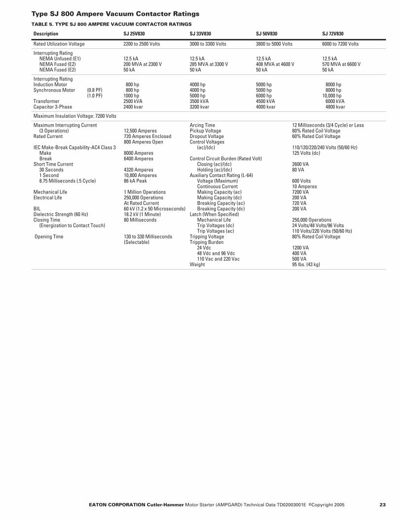
Type SJ 800 Ampere Vacuum Contactor RatingsTABLE 5. TYPE SJ 800 AMPERE VACUUM CONTACTOR RATINGS
Description SJ 25V830 SJ 33V830 SJ 50V830 SJ 72V830
Rated Utilization Voltage 2200 to 2500 Volts 3000 to 3300 Volts 3800 to 5000 Volts 6000 to 7200 Volts
Interrupting RatingNEMA Unfused (E1)NEMA Fused (E2)NEMA Fused (E2)
12.5 kA200 MVA at 2300 V50 kA
12.5 kA285 MVA at 3300 V50 kA
12.5 kA408 MVA at 4600 V50 kA
12.5 kA570 MVA at 6600 V50 kA
Interrupting RatingInduction MotorSynchronous Motor (0.8 PF)
(1.0 PF)TransformerCapacitor 3-Phase
800 hp 800 hp1000 hp2500 kVA2400 kvar
4000 hp4000 hp5000 hp3500 kVA3200 kvar
5000 hp5000 hp6000 hp4500 kVA4000 kvar
8000 hp 8000 hp10,000 hp 6000 kVA 4800 kvar
Maximum Insulation Voltage: 7200 Volts
Maximum Interrupting Current (3 Operations) 12,500 Amperes
Rated Current 720 Amperes Enclosed800 Amperes Open
IEC Make-Break Capability-AC4 Class 3Make 8000 AmperesBreak 6400 Amperes
Short Time Current30 Seconds 4320 Amperes1 Second 10,800 Amperes8.75 Milliseconds (.5 Cycle) 86 kA Peak
Mechanical Life 1 Million OperationsElectrical Life 250,000 Operations
At Rated CurrentBIL 60 kV (1.2 x 50 Microseconds)Dielectric Strength (60 Hz) 18.2 kV (1 Minute)Closing Time 80 Milliseconds
(Energization to Contact Touch)
Opening Time 130 to 330 Milliseconds (Selectable)
Arcing Time 12 Milliseconds (3/4 Cycle) or LessPickup Voltage 80% Rated Coil VoltageDropout Voltage 60% Rated Coil VoltageControl Voltages
(ac)/(dc) 110/120/220/240 Volts (50/60 Hz)125 Volts (dc)
Control Circuit Burden (Rated Volt)Closing (ac)/(dc) 2600 VAHolding (ac)/(dc) 80 VA
Auxiliary Contact Rating (L-64)Voltage (Maximum) 600 VoltsContinuous Current 10 AmperesMaking Capacity (ac) 7200 VAMaking Capacity (dc) 200 VABreaking Capacity (ac) 720 VABreaking Capacity (dc) 200 VA
Latch (When Specified)Mechanical Life 250,000 OperationsTrip Voltages (dc) 24 Volts/48 Volts/96 VoltsTrip Voltages (ac) 110 Volts/220 Volts (50/60 Hz)
Tripping Voltage 80% Rated Coil VoltageTripping Burden
24 Vdc 1200 VA48 Vdc and 96 Vdc 400 VA110 Vac and 220 Vac 500 VA
Weight 95 lbs. (43 kg)
24 EATON CORPORATION Cutler-Hammer Motor Starter (AMPGARD) Technical Data TD02003001E Effective: December 2005
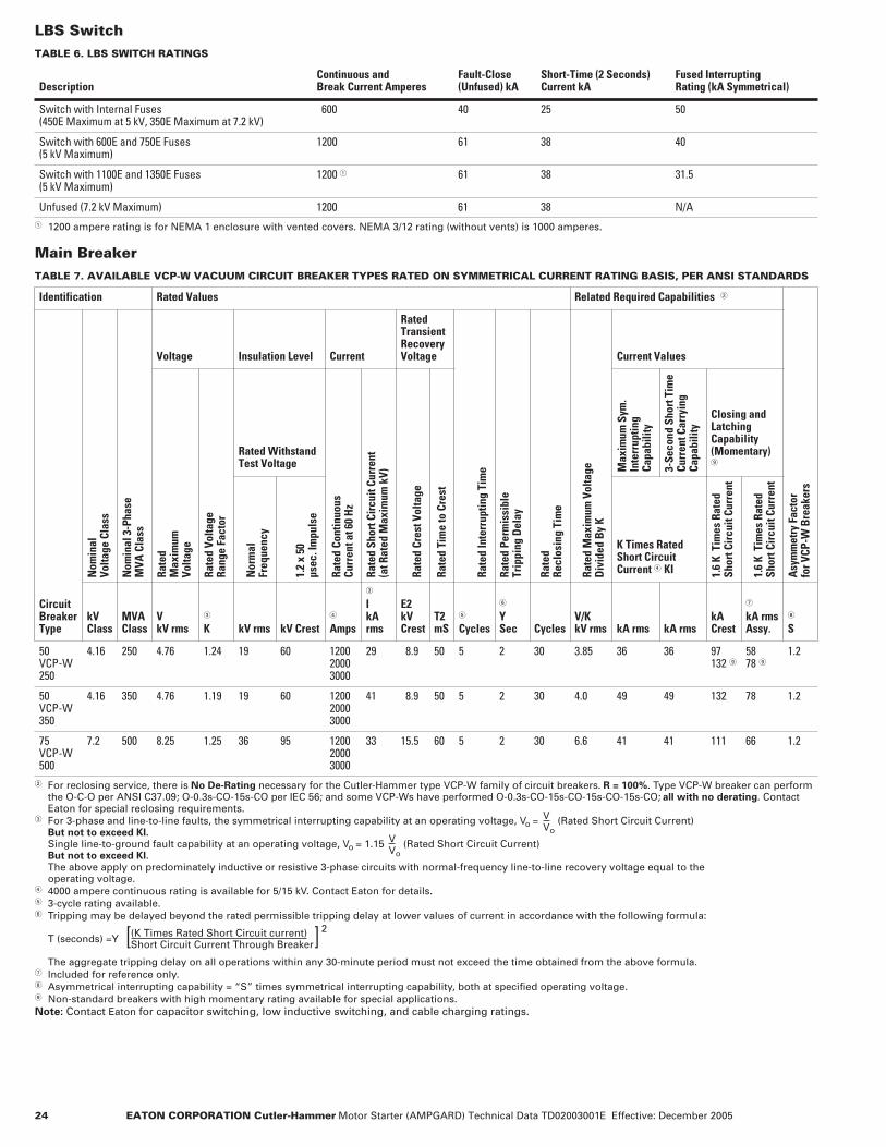
LBS SwitchTABLE 6. LBS SWITCH RATINGS
� 1200 ampere rating is for NEMA 1 enclosure with vented covers. NEMA 3/12 rating (without vents) is 1000 amperes.
Main BreakerTABLE 7. AVAILABLE VCP-W VACUUM CIRCUIT BREAKER TYPES RATED ON SYMMETRICAL CURRENT RATING BASIS, PER ANSI STANDARDS
� For reclosing service, there is No De-Rating necessary for the Cutler-Hammer type VCP-W family of circuit breakers. R = 100%. Type VCP-W breaker can perform the O-C-O per ANSI C37.09; O-0.3s-CO-15s-CO per IEC 56; and some VCP-Ws have performed O-0.3s-CO-15s-CO-15s-CO-15s-CO; all with no derating. Contact Eaton for special reclosing requirements.
� For 3-phase and line-to-line faults, the symmetrical interrupting capability at an operating voltage, Vo = (Rated Short Circuit Current)But not to exceed KI.Single line-to-ground fault capability at an operating voltage, Vo = 1.15 (Rated Short Circuit Current)But not to exceed KI.The above apply on predominately inductive or resistive 3-phase circuits with normal-frequency line-to-line recovery voltage equal to the operating voltage.
� 4000 ampere continuous rating is available for 5/15 kV. Contact Eaton for details.� 3-cycle rating available.� Tripping may be delayed beyond the rated permissible tripping delay at lower values of current in accordance with the following formula:
T (seconds) =Y
The aggregate tripping delay on all operations within any 30-minute period must not exceed the time obtained from the above formula.� Included for reference only.� Asymmetrical interrupting capability = “S” times symmetrical interrupting capability, both at specified operating voltage. Non-standard breakers with high momentary rating available for special applications.Note: Contact Eaton for capacitor switching, low inductive switching, and cable charging ratings.
DescriptionContinuous and Break Current Amperes
Fault-Close(Unfused) kA
Short-Time (2 Seconds)Current kA
Fused Interrupting Rating (kA Symmetrical)
Switch with Internal Fuses(450E Maximum at 5 kV, 350E Maximum at 7.2 kV)
600 40 25 50
Switch with 600E and 750E Fuses(5 kV Maximum)
1200 61 38 40
Switch with 1100E and 1350E Fuses(5 kV Maximum)
1200 � 61 38 31.5
Unfused (7.2 kV Maximum) 1200 61 38 N/A
Identification Rated Values Related Required Capabilities �
Asy
mm
etry
Fac
tor
for V
CP-W
Bre
aker
s
CircuitBreakerType
Nom
inal
Volta
ge C
lass
Nom
inal
3-P
hase
MVA
Cla
ss
Voltage Insulation Level Current
RatedTransientRecoveryVoltage
Rate
d In
terr
uptin
g Ti
me
Rate
d Pe
rmis
sibl
eTr
ippi
ng D
elay
Rate
d Re
clos
ing
Tim
e
Rate
d M
axim
um V
olta
geD
ivid
ed B
y K
Current Values
Rate
dM
axim
um
Volta
ge
Rate
d Vo
ltage
Rang
e Fa
ctor
Rated WithstandTest Voltage
Rate
d Co
ntin
uous
Cu
rren
t at 6
0 H
z
Rate
d Sh
ort C
ircu
it Cu
rren
t(a
t Rat
ed M
axim
um k
V)
Rate
d Cr
est V
olta
ge
Rate
d Ti
me
to C
rest
Max
imum
Sym
.In
terr
uptin
gCa
pabi
lity
3-Se
cond
Sho
rt T
ime
Curr
ent C
arry
ing
Capa
bilit
y
Closing andLatchingCapability(Momentary)
Nor
mal
Freq
uenc
y
1.2
x 50
µsec
. Im
puls
e
K Times Rated Short Circuit Current � KI 1.
6 K
Tim
es R
ated
Sh
ort C
ircu
it Cu
rren
t
1.6
K T
imes
Rat
ed
Shor
t Cir
cuit
Curr
ent
kVClass
MVAClass
VkV rms
�
K kV rms kV Crest�
Amps
�
IkArms
E2kVCrest
T2mS
�
Cycles
�
YSec Cycles
V/KkV rms kA rms kA rms
kACrest
�
kA rmsAssy.
�
S
50 VCP-W250
4.16 250 4.76 1.24 19 60 120020003000
29 8.9 50 5 2 30 3.85 36 36 97132
5878
1.2
50 VCP-W350
4.16 350 4.76 1.19 19 60 120020003000
41 8.9 50 5 2 30 4.0 49 49 132 78 1.2
75 VCP-W500
7.2 500 8.25 1.25 36 95 120020003000
33 15.5 60 5 2 30 6.6 41 41 111 66 1.2
VVo
VVo
(K Times Rated Short Circuit current)Short Circuit Current Through Breaker[ ]
2
EATON CORPORATION Cutler-Hammer Motor Starter (AMPGARD) Technical Data TD02003001E ©Copyright 2005 25
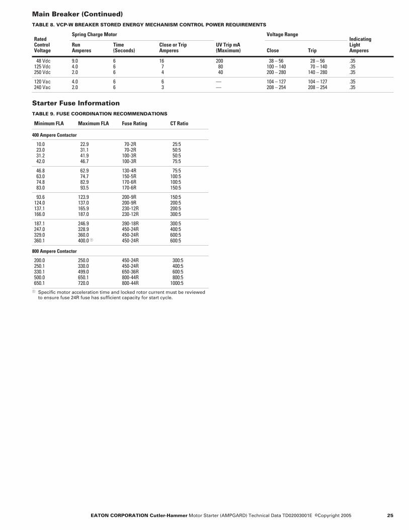
Main Breaker (Continued)TABLE 8. VCP-W BREAKER STORED ENERGY MECHANISM CONTROL POWER REQUIREMENTS
Starter Fuse InformationTABLE 9. FUSE COORDINATION RECOMMENDATIONS
� Specific motor acceleration time and locked rotor current must be reviewed to ensure fuse 24R fuse has sufficient capacity for start cycle.
RatedControl Voltage
Spring Charge Motor
UV Trip mA(Maximum)
Voltage RangeIndicatingLight Amperes
RunAmperes
Time(Seconds)
Close or TripAmperes Close Trip
48 Vdc125 Vdc250 Vdc
9.04.02.0
666
16 7 4
200 80 40
38 – 56100 – 140200 – 280
28 – 56 70 – 140140 – 280
.35
.35
.35
120 Vac240 Vac
4.02.0
66
6 3
——
104 – 127208 – 254
104 – 127208 – 254
.35
.35
Minimum FLA Maximum FLA Fuse Rating CT Ratio
400 Ampere Contactor
10.0 23.0 31.2 42.0
22.9 31.1 41.9 46.7
70-2R 70-2R100-3R100-3R
25:5 50:5 50:5 75:5
46.8 63.0 74.8 83.0
62.9 74.7 82.9 93.5
130-4R150-5R170-6R170-6R
75:5100:5100:5150:5
93.6124.0137.1166.0
123.9137.0165.9187.0
200-9R200-9R230-12R230-12R
150:5200:5200:5300:5
187.1247.0329.0360.1
246.9328.9360.0400.0 �
390-18R450-24R450-24R450-24R
300:5400:5600:5600:5
800 Ampere Contactor
200.0250.1330.1500.0650.1
250.0330.0499.0650.1720.0
450-24R450-24R650-36R800-44R800-44R
300:5 400:5 600:5 800:51000:5

26 EATON CORPORATION Cutler-Hammer Motor Starter (AMPGARD) Technical Data TD02003001E Effective: December 2005
Layout Dimensions
Full Voltage Squirrel Cage Starters Catalog S210 Non-Reversing Catalog S310 Reversing
Equipment Details
Mounted in the Medium Voltage Section
● Three incoming line connectors.
● Drawout 3-pole gang-operated line isolating switch assembly with isolating shutter, external operating handle interlocked to prevent opening the medium voltage compartment door until the isolating switch is open and grounded.
● Vertically mounted current limiting power fuses with pop-up blown fuse indicators.
● One magnetic 3-pole vacuum contactor with dc operating coils and mechanical interlock to prevent opening the isolating switch when contactor is closed.
● One control power transformer (115-volt secondary).
● Two CPT primary current limiting fuses.
● One control circuit secondary fuse.
● One run-test circuit.● Four electrical interlocks
(2NO, 2NC).● Three current transformers.
Reversing Starter
One additional magnetic 3-pole vacuum contactor (duplicate of above), both contactors are mechanically and electrically interlocked.
Mounted in the Low Voltage Compartment
● Control panel with:– One MP-3000 motor
protection relay– One interposing control relay
● Set of control circuit terminal blocks.
Specifications
TABLE 10. STARTER SELECTION INFORMATION — DIMENSIONS IN INCHES (MM)
� Horsepower based on NEMA standard design B motor at 1800 rpm.� When horizontal bus is added, height becomes 92 inches (2337 mm).� At higher hp rating, maximum acceleration time is 3.5 seconds.� At higher hp rating, maximum acceleration time is 6 seconds.� Maximum current for 2 starters in a single structure is 720 amperes.� May be applied on 6900 volt systems where maximum voltage does not exceed 7200 volts.
FIGURE 9. STARTER ARRANGEMENTS
Horsepower � Volts Cont
acto
rA
mpe
re R
atin
g(E
nclo
sed)
Star
ter
Inte
rrup
ting
Ratin
g(k
VA)
Equi
pmen
tA
rran
gem
ent
Num
ber
Dimensions
Add.StarterSpaces
Weight Lbs. (kg)Height � Width Depth
2200 – 2400 Volts Non-Reversing
700/800 �1500/1750 �3000
230023002300
400400720
200,000200,000200,000
112
80 (2032)80 (2032)80 (2032)
36 (914)36 (914)36 (914)
30 (762)30 (762)30 (762)
1 �1 �0
1350 (613)1350 (613)1700 (772)
2200 – 2400 Volts Reversing
700/800 �1500/1750 �3000
230023002300
400400720
200,000200,000200,000
334
80 (2032)80 (2032)80 (2032)
36 (914)36 (914)36 (914)
30 (762)30 (762)30 (762)
000
1800 (817)1800 (817)2400 (1090)
4000 – 4800 Volts Non-Reversing
1250/1500 �2500/3000 �5500
460046004600
400400720
400,000400,000400,000
112
80 (2032)80 (2032)80 (2032)
36 (914)36 (914)36 (914)
30 (762)30 (762)30 (762)
1 �1 �0
1350 (613)1350 (613)1700 (772)
4000 – 4800 Volts Reversing
1250/1500 �2500/3000 �5500
460046004600
400400720
400,000400,000400,000
334
80 (2032)80 (2032)80 (2032)
36 (914)36 (914)36 (914)
30 (762)30 (762)30 (762)
000
1800 (817)1800 (817)2400 (1090)
6600 Volts Non-Reversing
2000/2250 �4000/4500 �8000
6600 �6600 �6600 �
400400720
570,000570,000570,000
112
80 (2032)80 (2032)80 (2032)
36 (914)36 (914)36 (914)
30 (762)30 (762)30 (762)
1 �1 �0
1500 (681)1500 (681)1800 (817)
6600 Volts Reversing
2000/2250 �4000/4500 �8000
6600 �6600 �6600 �
400400720
570,000570,000570,000
334
80 (2032)80 (2032)80 (2032)
36 (914)36 (914)36 (914)
30 (762)30 (762)30 (762)
000
1800 (817)1800 (817)2400 (1090)
Dimensions for estimating purposes only.
M
M
M
RVS
M
RVS
Arrangement 1 Arrangement 4Arrangement 3Arrangement 2

EATON CORPORATION Cutler-Hammer Motor Starter (AMPGARD) Technical Data TD02003001E ©Copyright 2005 27
FIGURE 10. ARRANGEMENT 1 DETAIL (FULL VOLTAGE 400 AMPERES) — SEE TABLE 17 ON PAGE 36 FOR NOTES
FIGURE 11. ARRANGEMENT 2 DETAIL (FULL VOLTAGE 800 AMPERES) — SEE TABLE 17 ON PAGE 36 FOR NOTES
Gnd
Side View
BusPh
Main
caPhb
Con
trol
1200 Amp - 4.00" X 1/Ph
1200 Ampere Main Bus
Co
ntro
l
Note A
Note C1
Note C
Note B
Note D
Note T
Top View
Floor Plan
Main Bus
Front View
Detail A
in Starteron Rear Wall Load PanelW ll L d P
Load TermsT1 T3
Load TermDetail ANote L
Load TermDetail ANote L
4.38(111)
36.00(914)
3.50(89)
5.81(148)
62.00 (1575)
22.00(559)
5.81(148)
7.39(188)
12.00(305)
30.00 (762)
1.50 (38)
2.00 (51)
5.50 (140)
3.00 (76)6.00 (152)
6.00 (152)
3.00 (76)
9.25 (235)
5.50 (140)
6.80 (173)
4.63 (118)
9.32 (237)
1.25 (32)13.50
(343)
36.00(914)
36.00(914)
4.50(114)
1.18(30)
(35)
(51)
2.00(51)
2.00(51)
3.00(76)
80.00(2032)
61.00(1549)
21.00 (533)
7.39(188)1.45
22.85(580)
30.00(762)
30.00 (762)
28.00 (711)
1.00(25)
4.50(114)
13.75(349) (58)2.50
(64)
27.00(686)
21.67 (550)
4.38(111)
12.00(305)
80.00(2032)
31.75 (806)
7.39(188)
1.45(37)
22.85(580)
29.00(737)
5.81(148)
30.00(762)
2.00(51)
2.00(51)
27.00(686)
1.25 (32)13.50
(343)1.50 (38)
30.00 (762)
(237)
3.00 (76)
1.36(35)
36.00(914)
30.00 (762)
28.00 (711)
21.67(550)
1.00(25)
36.00(914)
2.50(64)
13.75 2.31(59)
4.63 (118)
6.00 (152)
5.50 (140)
5.50 (140)
6.80 (173)
4.50 (114)
4.50 (114)3.00 (76)
1.00 (25)
1.18 (30)
Side View
BusPh
Main
ca
Low
Vol
tage
Cont
rol
Front View
800 Ampere Starter
Note A
Note G
Note G
Note D
Note E
Top View
Floor Plan
Main Bus
T3Load Term
on Rear Wall Load Panelin Starter
Detail A
Note LDetail ALoad Term
4.3(109)
4.3(109)

28 EATON CORPORATION Cutler-Hammer Motor Starter (AMPGARD) Technical Data TD02003001E Effective: December 2005
Primary Reactor, Reduced Voltage Starters Catalog S510 Non-Reversing Catalog S710 Reversing — Main Structure
Mounted in the Medium Voltage Section
● Three incoming line connectors.
● One drawout 3-pole gang-operated line isolation switch assembly with isolating shutter, external operating handle interlocked to prevent opening the medium voltage compartment door until the isolating switch is open and grounded.
● One vertically mounted current limiting power fuse with pop-up blown fuse indicators.
● One magnetic 3-pole vacuum contactor with dc operating coils and mechanical interlock to prevent opening the isolation switch when the contactor is closed.
● One control power transformer (115-volt secondary).
● Two CPT primary current limiting fuses.
● One control circuit secondary fuse.
● One run-test circuit.● Four electrical interlocks
(2NO, 2NC).
Reversing Starter
One additional magnetic con-tactor (duplicate of above), both contactors are mechanically and electrically interlocked.
Mounted in the Low Voltage Compartment
● One control panel with:– One MP-3000 motor
protection relay– Two interposing relays
● One set of control circuit terminal blocks.
Reduced Voltage Structure
● One magnetic 3-pole vacuum run contactor with dc operating coil and electrical interlocks.
● Three current transformers.● One medium-duty starting
reactor with 50 – 65 – 80% taps.
Starting Characteristics
TABLE 11. TYPE 502 REACTOR STARTING CHARACTERISTICS
� Factory set on 65% tap.
Specifications
TABLE 12. STARTER SELECTION INFORMATION — DIMENSIONS IN INCHES (MM)
� Horsepower based on NEMA standard design B motor at 1800 rpm.� When horizontal bus is added, height becomes 92 inches (2337 mm).� At higher hp rating maximum acceleration time is 3.5 seconds.� At higher hp rating maximum acceleration time is 6 seconds.
FIGURE 12. STARTER ARRANGEMENTS
StarterType % M
otor
Vol
tage
% Mot
or C
urre
nt
%
Line
Cur
rent
% T
orqu
e
80% Tap65% Tap �50% Tap
806550
806550
806550
644225
Horsepower � Volts Cont
acto
rA
mpe
re R
atin
g(E
nclo
sed)
Star
ter
Inte
rrup
ting
Ratin
g (k
VA)
Equi
pmen
tA
rran
gem
ent
Num
ber
Dimensions
Weight Lbs. (kg)Height � Width Depth
2200 – 2400 Volts Non-Reversing
700/800 �1500/1750 �3000
230023002300
400400720
200,000200,000200,000
112
80 (2032)80 (2032)80 (2032)
72 (1829)72 (1829)72 (1829)
30 (762)30 (762)30 (762)
2800 (1271)2800 (1271)4000 (1816)
2200 – 2400 Volts Reversing
700/800 �1500/1750 �3000
230023002300
400400720
200,000200,000200,000
334
80 (2032)80 (2032)80 (2032)
72 (1829)72 (1829)72 (1829)
30 (762)30 (762)30 (762)
3250 (1476)3250 (1476)4650 (2111)
4000 – 4800 Volts Non-Reversing
1250/1500 �2500/3000 �5500
460046004600
400400720
400,000400,000400,000
112
80 (2032)80 (2032)80 (2032)
72 (1829)72 (1829)72 (1829)
30 (762)30 (762)30 (762)
2800 (1271)2800 (1271)4000 (1816)
4000 – 4800 Volts Reversing
1250/1500 �2500/3000 �5500
460046004600
400400720
400,000400,000400,000
334
80 (2032)80 (2032)80 (2032)
72 (1829)72 (1829)72 (1829)
30 (762)30 (762)30 (762)
3250 (1476)3250 (1476)4650 (2111)
6600 Volts Non-Reversing
2000/2250 �4000/4500 �8000
660066006600
400400720
570,000570,000570,000
112
80 (2032)80 (2032)80 (2032)
72 (1829)72 (1829)72 (1829)
30 (762)30 (762)30 (762)
3300 (1498)3300 (1498)4650 (2111)
6600 Volts Reversing
2000/2250 �4000/4500 �8000
660066006600
400400720
570,000570,000570,000
334
80 (2032)80 (2032)80 (2032)
72 (1829)72 (1829)72 (1829)
30 (762)30 (762)30 (762)
3250 (1476)3250 (1476)4650 (2111)
Dimensions for estimating purposes only.
Reactor
R
Reactor
R
RVS Reactor
R
RVSReactor
R
M
Arrangement 1 Arrangement 2 Arrangement 3 Arrangement 4

EATON CORPORATION Cutler-Hammer Motor Starter (AMPGARD) Technical Data TD02003001E ©Copyright 2005 29
FIGURE 13. ARRANGEMENT 1 DETAIL (REDUCED VOLTAGE, 400 AMPERES) — SEE TABLE 17 ON PAGE 36 FOR NOTES
Floor Plan
Note ABusGnd
Side View
Load Term
Cont
rol
Front View
RVNR 400 Ampere Starter w/Main Bus 1200 Amperes
Note G
Note D
Note G
Load Term
Note L1
Main Bus
bPh
a c
MainPh Ph1200 Amp - 4.00" X 1/Php /
61.00 (1549)
3.50 (89) 12.00
(305)
7.39
80.00 (2032)
61.00 (1549)
22.00(559) 1.45
(37)
22.85(580)
30.00(762)
2.50 (64)
2.00 (51)
2.00(51)
13.50 (343) 1.25
(32)1.50(38)( )
1.70(43)
2.88(73)
27.00(686)
4.50(114)
28.00(711)
21.67(550)
1.00(25)
28.00(711)
4.63(118)
13.75(349)( )
4.50(114)
4.50
36.00(914)
36.00(914)
36.00(914) 27.00 (686)
5.50 (140)5.50 (140)2.00 (51)
36.00 (914)
1.00 (25)
1.00 (25)
1.00 (25)
6.00 (152)2.31 (59)
3.00 (76)
30.00 (762)
30.00 (762)
9.32(237)
5.81(148)
2.92 (74)4.38 (111)4.38 (111)

30 EATON CORPORATION Cutler-Hammer Motor Starter (AMPGARD) Technical Data TD02003001E Effective: December 2005
Reduced Voltage Autotransformer StartersCatalog S610 Non-Reversing Catalog S810 Reversing —Main Structure
Mounted in the Medium Voltage Section
● Three incoming line connectors.
● One drawout 3-pole gang-operated line isolation switch assembly with isolating shutter, external operating handle interlocked to prevent opening the medium voltage compartment door until the isolating switch is open and grounded.
● Three vertically mounted current limiting power fuses with pop-up blown fuse indicators.
● One magnetic 3-pole vacuum contactor with dc operating coils and mechanical interlock to prevent opening the isolation switch when the contactor is closed.
● One control power transformer (115-volt secondary).
● Two CPT primary current limiting fuses.
● One control circuit secondary fuse.
● One run-test circuit.● Four electrical interlocks
(2NO, 2NC).
Reversing Starter
One additional magnetic con-tactor (duplicate of above), both contactors are mechanically and electrically interlocked.
Mounted in the Low Voltage Compartment
● One control panel with:– One MP-3000 motor
protection relay– Three interposing relays
● One set of control circuit terminal blocks.
Reduced Voltage Structure(s)
● One magnetic 3-pole vacuum run contactor with dc operating coil and electrically and mechanically interlocked with the starting contactor.
● One magnetic 2-pole vacuum start contactor with dc operating coil and electrical and mechanical interlocks.
● Three current transformers.● One medium-duty starting
autotransformer with 50 – 65 – 80% taps.
● Three distribution class lightning arresters for high voltage stress protection on the transformer zero tap.
Starting Characteristics
TABLE 13. TYPE 602 AUTO-TRANSFORMER STARTING CHARACTERISTICS
� Factory set on 65% tap.
SpecificationsTABLE 14. STARTER SELECTION INFORMATION — DIMENSIONS IN INCHES (MM)
� Horsepower based on NEMA standard design B motor at 1800 rpm.� When horizontal bus is added, height becomes 92 inches (2337 mm).� At higher hp rating, maximum acceleration time is 3.5 seconds.� At higher hp rating, maximum acceleration time is 6 seconds.
FIGURE 14. STARTER ARRANGEMENTS
StarterType % M
otor
Vol
tage
% Mot
or C
urre
nt
%
Line
Cur
rent
% T
orqu
e
80% Tap65% Tap �50% Tap
806550
806550
674528
644225
Horsepower � Volts Cont
acto
rA
mpe
re R
atin
g(E
nclo
sed)
Star
ter
Inte
rrup
ting
Ratin
g (k
VA)
Equi
pmen
tA
rran
gem
ent
Num
ber
Dimensions
Number ofStructures
WeightLbs. (kg)Height � Width Depth
2200 – 2400 Volts Non-Reversing
700/800 �1500/1750 �3000
230023002300
400400720
200,000200,000200,000
112
80 (2032)80 (2032)80 (2032)
72 (1829) 72 (1829)108 (2743)
30 (762)30 (762)30 (762)
223
3100 (1407)3100 (1407)4800 (2179)
2200 – 2400 Volts Reversing
700/800 �1500/1750 �3000
230023002300
400400720
200,000200,000200,000
334
80 (2032)80 (2032)80 (2032)
72 (1829) 72 (1829)108 (2743)
30 (762)30 (762)30 (762)
223
3650 (1657)3650 (1657)5650 (2565)
4000 – 4800 Volts Non-Reversing
1250/1500 �2500/3000 �5500
460046004600
400400720
400,000400,000400,000
112
80 (2032)80 (2032)80 (2032)
72 (1829) 72 (1829)108 (2743)
30 (762)30 (762)30 (762)
223
3100 (1407)3100 (1407)4800 (2179)
4000 – 4800 Volts Reversing
1250/1500 �2500/3000 �5500
460046004600
400400720
400,000400,000400,000
334
80 (2032)80 (2032)80 (2032)
72 (1829) 72 (1829)108 (2743)
30 (762)30 (762)30 (762)
223
3650 (1657)3650 (1657)5650 (2565)
6600 Volts Non-Reversing
2000/2250 �4000/4500 �8000
660066006600
400400720
570,000570,000570,000
112
80 (2032)80 (2032)80 (2032)
72 (1829) 72 (1829)108 (2743)
30 (762)30 (762)30 (762)
223
3100 (1407)3100 (1407)4800 (2179)
6600 Volts Reversing
2000/2250 �4000/4500 �8000
660066006600
400400720
570,000570,000570,000
334
80 (2032)80 (2032)80 (2032)
72 (1829) 72 (1829)108 (2743)
30 (762)30 (762)30 (762)
334
3650 (1657)3650 (1657)5650 (2565)
Dimensions for estimating purposes only.
Auto
S
R
M
Auto
S
RM
AutoRVS
S
RM Auto
RVS
S
R
M
Arrangement 1 Arrangement 2 Arrangement 3 Arrangement 4
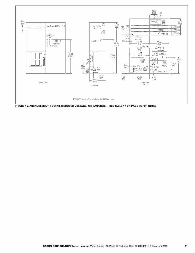
EATON CORPORATION Cutler-Hammer Motor Starter (AMPGARD) Technical Data TD02003001E ©Copyright 2005 31
FIGURE 15. ARRANGEMENT 1 DETAIL (REDUCED VOLTAGE, 400 AMPERES) — SEE TABLE 17 ON PAGE 36 FOR NOTES
Floor Plan
Note ABusGnd
Side View
Load Term
Cont
rol
Front View
RVNR 400 Ampere Starter w/Main Bus 1200 Amperes
Note G
Note D
Note G
Load Term
Note L1
Main Bus
bPh
a c
MainPh Ph1200 Amp - 4.00" X 1/Php /
61.00 (1549)
3.50 (89) 12.00
(305)
7.39
80.00 (2032)
61.00 (1549)
22.00(559) 1.45
(37)
22.85(580)
30.00(762)
2.50 (64)
2.00 (51)
2.00(51)
13.50 (343) 1.25
(32)1.50(38)( )
1.70(43)
2.88(73)
27.00(686)
4.50(114)
28.00(711)
21.67(550)
1.00(25)
28.00(711)
4.63(118)
13.75(349)( )
4.50(114)
4.50
36.00(914)
36.00(914)
36.00(914) 27.00 (686)
5.50 (140)5.50 (140)2.00 (51)
36.00 (914)
1.00 (25)
1.00 (25)
1.00 (25)
6.00 (152)2.31 (59)
3.00 (76)
30.00 (762)
30.00 (762)
9.32(237)
5.81(148)
2.92 (74)4.38 (111)4.38 (111)

32 EATON CORPORATION Cutler-Hammer Motor Starter (AMPGARD) Technical Data TD02003001E Effective: December 2005
Full Voltage Synchronous Starters Brush Type Mark V Solid-State Catalog S241 Non-Reversing Catalog S341 Reversing — Main Structure
Mounted in the Medium Voltage Section
● Three incoming line connectors.
● One drawout 3-pole gang-operated line isolation switch assembly with isolating shutter. External operating handle interlocked to prevent opening the medium voltage compartment door until the isolating switch is open and grounded.
● Three vertically mounted current limiting power fuses with pop-up blown fuse indicators.
● One magnetic 3-pole vacuum contactor with dc operating coils and mechanical interlock to prevent opening the isolation switch when the contactor is closed.
● One control power transformer (115-volt secondary).
● Two CPT primary current limiting fuses.
● One control circuit secondary fuse.
● One run-test circuit.● Four electrical interlocks
(2NO, 2NC).● Three current transformers.
Reversing Starter
One additional magnetic con-tactor (duplicate of above), both contactors are mechanically and electrically interlocked.
Mounted in the Low Voltage Compartment
● One control panel with:– One MP-3000 motor
protection relay– One interposing relay– One set of control circuit
terminal blocks
Mounted in the Upper Compartment or Auxiliary Structure
One brush-type solid-state Mark V field panel with:● Mounted on Door
– One ac line ammeter, panel type
– One dc field ammeter, panel type
– One exciter field potentiometer.
– One set of externally ventilated heatsinks
● Mounted on Inside Compartment– One step-down exciter
transformer 3-phase– One “SCR” power
supply panel– One synchronous
control board
– “MOV” surge protection– One field loss current
relay– One ammeter shunt– One set of control circuit
blocks– Three primary fuses– Three secondary fuses
● Mounted on Top of Starter– One starting and field
discharge resistor
TABLE 15. STARTER SELECTION INFORMATION — DIMENSIONS IN INCHES (MM)
� Horsepower based on NEMA standard design B motor at 1800 rpm.� When horizontal bus is added, height becomes 92 inches (2337 mm).� Starting and discharge resistors are mounted on top, add 13 inches (330 mm) to the height.� At higher hp rating maximum acceleration time is 3.5 seconds.� At higher hp rating maximum acceleration time is 6 seconds.
FIGURE 16. STARTER ARRANGEMENTS� When the field panel requirement exceeds 88 amperes at 125 Vdc or 44 amperes at 250 Vdc, an auxiliary structure 36
inches (914.4 mm) wide is required.� Mounting location of exciter transformer when field panel requirement exceeds 88 amperes at 125 Vdc or 44 amperes at
250 Vdc. Otherwise compartment is blank.
Horsepowerat .8 PF �
Horsepowerat 1.0 PF Volts Co
ntac
tor
Am
pere
Rat
ing
(Enc
lose
d)
Star
ter
Inte
rrup
ting
Ratin
g (k
VA)
Equi
pmen
tA
rran
gem
ent
Num
ber
Dimensions
WeightLbs. (kg)
Height �� Width Depth
2200 – 2400 Volts Non-Reversing
700/800 �1500/1750 �3000
900/1000 �1750/2000 �3500
230023002300
400400720
200,000200,000200,000
112
80 (2032)80 (2032)80 (2032)
36 (914)36 (914)72 (1829)
30 (762)30 (762)30 (762)
1500 (681)1500 (681)2350 (1067)
2200 – 2400 Volts Reversing
700/800 �1500/1750 �3000
900/1000 �1750/2000 �3500
230023002300
400400720
200,000200,000200,000
334
80 (2032)80 (2032)80 (2032)
72 (1829)72 (1829)72 (1829)
30 (762)30 (762)30 (762)
2100 (953)2100 (953)2900 (1317)
4000 – 4800 Volts Non-Reversing
1250/1500 �2500/3000 �5500
1500/1750 �3000/3500 �6000
460046004600
400400720
400,000400,000400,000
112
80 (2032)80 (2032)80 (2032)
36 (914)36 (914)72 (1829)
30 (762)30 (762)30 (762)
1550 (704)1550 (704)2350 (1067)
4000 – 4800 Volts Reversing
1250/1500 �2500/3000 �5500
1500/1750 �3000/3500 �6000
460046004600
400400720
400,000400,000400,000
334
80 (2032)80 (2032)80 (2032)
72 (1829)72 (1829)72 (1829)
30 (762)30 (762)30 (762)
2100 (953)2100 (953)2900 (1317)
6600 Volts Non-Reversing
2000/2250 �4000/4500 �8000
2500/2750 �5000/5500 �10,000
720072007200
400400720
570,000570,000570,000
112
80 (2032)80 (2032)80 (2032)
36 (914)36 (914)72 (1829)
30 (762)30 (762)30 (762)
1700 (772)1700 (772)2500 (1135)
6600 Volts Reversing
2000/2250 �4000/4500 �8000
2500/2750 �5000/5500 �10,000
720072007200
400400720
570,000570,000570,000
334
80 (2032)80 (2032)80 (2032)
72 (1829)72 (1829)72 (1829)
30 (762)30 (762)30 (762)
2100 (953)2100 (953)2900 (1317)
Dimensions for estimating purposes only.
3
6
7
Field Panel
M
3
7
Field Panel
RVS
M
3
7
Field Panel
RVS
M
3
7
Field Panel
M
Arrangement 1 Arrangement 2 Arrangement 3 Arrangement 4

EATON CORPORATION Cutler-Hammer Motor Starter (AMPGARD) Technical Data TD02003001E ©Copyright 2005 33
FIGURE 17. ARRANGEMENT 1 DETAIL (400 AMPERES, SYNCHRONOUS) — SEE TABLE 17 ON PAGE 36 FOR NOTES
12.00(305)
80.00(2032)
22.00(559)
1.45(37)
7.39(188)
21.00(533)
22.85(580)
30.00(762)
2.00(51)
27.00(686)
4.50(114)
21.67(550)
28.00(711)
30.00(762)
2.31(59)
1.00(
(25)5.81(148)
5.50
5.50
6.802.00 (51)
3.00 (76)
6.00 (152)1.00 (25)
13.75 (349)
13.50(343)
1.50(38)12.25
(311)
25.0(635)
3.50(90)
36.00(914)
3.00(76)
1.18(30)
2.50(64)
4.13(105)
36.00(914)
36.00(914)
4.50(114)
2.00(51)
1.25 (32)
30.00
4.38 (111) 4.38 (111)
(140)
(173)
(762)
BusGnd
Side View
BusPhPh
Main
ca
Load Term
T3T2T1
Phb
Load Term
Low
Volt
age
Co
ntro
l
Front View
1000 Amp - 3.00" X 1/Php /
1000 Ampere Main Bus
Note A
Note G
Note G
Note E
Note D
Note E
Top View
Floor Plan
Main Bus
Synchronous Starter
Detail ANote L
On Rear Wall Load PanelW ll L d Pin Starter
Detail A
DC F
ield
Conn
's M
TDon
rh S
ide
Starting &Discharge res.
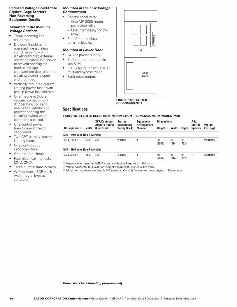
34 EATON CORPORATION Cutler-Hammer Motor Starter (AMPGARD) Technical Data TD02003001E Effective: December 2005
Reduced Voltage Solid-State Squirrel Cage Starters Non-Reversing —Equipment Details
Mounted in the Medium Voltage Sections
● Three incoming line connectors.
● Drawout 3-pole gang-operated line isolating switch assembly with isolating shutter, external operating handle interlocked to prevent opening the medium voltage compartment door until the isolating switch is open and grounded.
● Vertically mounted current limiting power fuses with pop-up blown fuse indicators.
● One magnetic 3-pole vacuum contactor with dc operating coils and mechanical interlock to prevent opening the isolating switch when contactor is closed.
● One control power transformer (115-volt secondary).
● Two CPT primary current limiting fuses.
● One control circuit secondary fuse.
● One run-test circuit.● Four electrical interlocks
(2NO, 2NC).● Three current transformers.● Withdrawable SCR truck
with integral bypass contactor.
Mounted in the Low Voltage Compartment
● Control panel with:– One MP-3000 motor
protection relay– One interposing control
relay● Set of control circuit
terminal blocks.
Mounted in Lower Door
● 24 Vdc power supply.● Soft start control module
and CIM.● Status lights for soft starter
fault and bypass mode.● Fault reset button.
FIGURE 18. STARTER ARRANGEMENT 1
SpecificationsTABLE 16. STARTER SELECTION INFORMATION — DIMENSIONS IN INCHES (MM)
� Horsepower based on NEMA standard design B motor at 1800 rpm.� When horizontal bus is added, height becomes 92 inches (2337 mm).� Maximum acceleration time is 180 seconds. Consult factory for times beyond 180 seconds.
SCR Truck
M
Horsepower � Volts
SCR/ContactorAmpere Rating(Enclosed)
StarterInterruptingRating (kVA)
EquipmentArrangementNumber
Dimensions Add.StarterSpaces
Weight Lbs. (kg)Height � Width Depth
2200 – 2400 Volts Non-Reversing
1500/1750 � 2300 400 200,000 1 80(2032)
36(914)
30(762)
1 2000 (908)
4000 – 4800 Volts Non-Reversing
2500/3000 � 4600 400 400,000 1 80(2032)
36(914)
30(762)
1 2000 (908)
Dimensions for estimating purposes only.

EATON CORPORATION Cutler-Hammer Motor Starter (AMPGARD) Technical Data TD02003001E ©Copyright 2005 35
FIGURE 19. ARRANGEMENT DETAIL (400 AMPERES REDUCED VOLTAGE SOLID-STATE) — SEE TABLE 17 ON PAGE 36 FOR NOTES
27.00 (686)
4.50 (114)
3.00(76)
(76)
6.00(152)
9.25(235)
4.63(118)
3.00(76)
1.36(35)
4.63(118)
1.18(30)
13.50(343)
1.50 (38)
9.32(237)
1.25 (32)
28.00(711)
21.67(550)
1.00(25))
2.31(59)
4.50 (114)
13.75(349)
6.00
30.00(762)
2.50(64)
2.00(51)
1.00(25)
2.00(51)
5.50(140)
(173)
36.00(914)
30.00(762)
36.00(914)
2.002 00(51)
30.00 (762)
22.85 (580)
62.00(1575)
5.81(148)
1.45(37)
7.39(188)1.45
(37)
61.00(1549)
3.50 (89)
12.00(305)
80.00(2032)
2.00(51)
36.00 (914)
Note G
Note E
Note D
Note G
Note E
Note A
Top View
Floor Plan
Main Bus
Load TerminalDetail ANote L
Low
Vol
tage
Con
trol
Side View
GroundBus
BusGround
PHA
PHB C
PH
BusMain
Assembly
In DoorCompt.
D
ControlRVSS Truck
RVSS
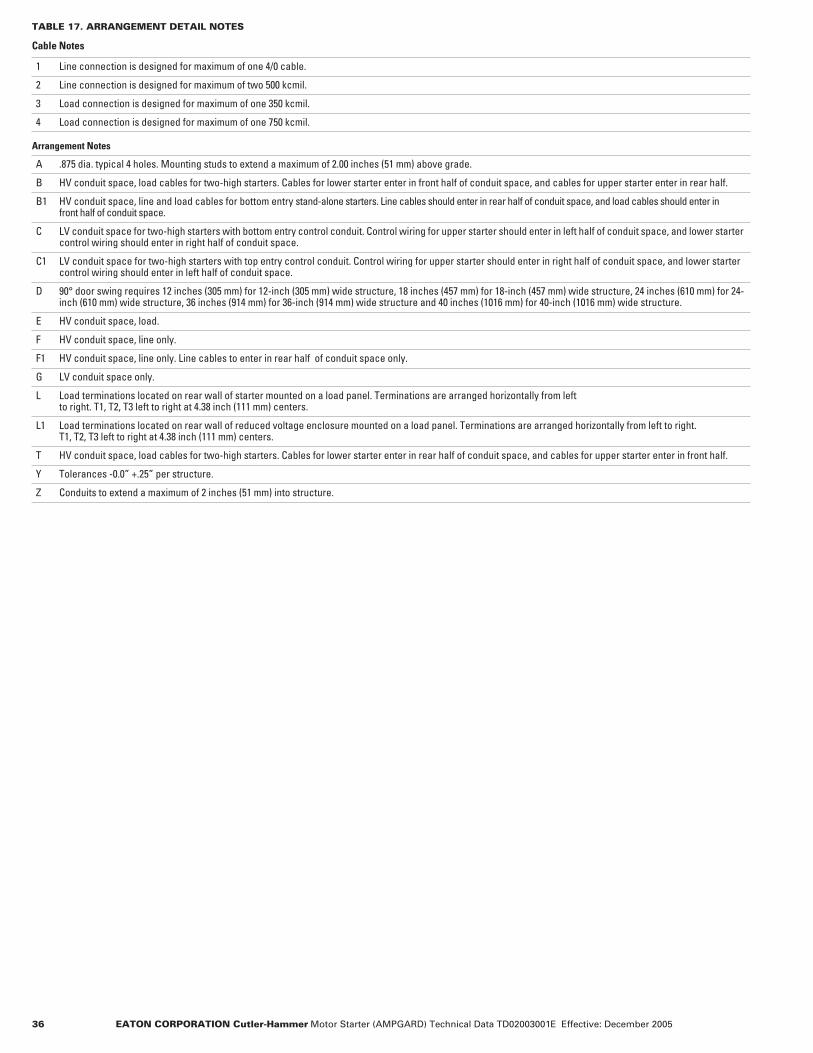
36 EATON CORPORATION Cutler-Hammer Motor Starter (AMPGARD) Technical Data TD02003001E Effective: December 2005
TABLE 17. ARRANGEMENT DETAIL NOTES
Cable Notes
1 Line connection is designed for maximum of one 4/0 cable.
2 Line connection is designed for maximum of two 500 kcmil.
3 Load connection is designed for maximum of one 350 kcmil.
4 Load connection is designed for maximum of one 750 kcmil.
Arrangement Notes
A .875 dia. typical 4 holes. Mounting studs to extend a maximum of 2.00 inches (51 mm) above grade.
B HV conduit space, load cables for two-high starters. Cables for lower starter enter in front half of conduit space, and cables for upper starter enter in rear half.
B1 HV conduit space, line and load cables for bottom entry stand-alone starters. Line cables should enter in rear half of conduit space, and load cables should enter in front half of conduit space.
C LV conduit space for two-high starters with bottom entry control conduit. Control wiring for upper starter should enter in left half of conduit space, and lower starter control wiring should enter in right half of conduit space.
C1 LV conduit space for two-high starters with top entry control conduit. Control wiring for upper starter should enter in right half of conduit space, and lower starter control wiring should enter in left half of conduit space.
D 90° door swing requires 12 inches (305 mm) for 12-inch (305 mm) wide structure, 18 inches (457 mm) for 18-inch (457 mm) wide structure, 24 inches (610 mm) for 24-inch (610 mm) wide structure, 36 inches (914 mm) for 36-inch (914 mm) wide structure and 40 inches (1016 mm) for 40-inch (1016 mm) wide structure.
E HV conduit space, load.
F HV conduit space, line only.
F1 HV conduit space, line only. Line cables to enter in rear half of conduit space only.
G LV conduit space only.
L Load terminations located on rear wall of starter mounted on a load panel. Terminations are arranged horizontally from left to right. T1, T2, T3 left to right at 4.38 inch (111 mm) centers.
L1 Load terminations located on rear wall of reduced voltage enclosure mounted on a load panel. Terminations are arranged horizontally from left to right. T1, T2, T3 left to right at 4.38 inch (111 mm) centers.
T HV conduit space, load cables for two-high starters. Cables for lower starter enter in rear half of conduit space, and cables for upper starter enter in front half.
Y Tolerances -0.0” +.25” per structure.
Z Conduits to extend a maximum of 2 inches (51 mm) into structure.

EATON CORPORATION Cutler-Hammer Motor Starter (AMPGARD) Technical Data TD02003001E ©Copyright 2005 37
Incoming Line/PT Layouts — Dimensions in Inches (mm)
FIGURE 20. INCOMING LINE — 24-INCH (610 MM) WIDE
Note: 24-inch (610 mm) incoming line with 1200 A main bus, PT/CPT disconnect and LV compartment for left-hand end of lineup. Righthand end of lineup is mirror image. As shown for top entry of incoming cable. For bottom entry, PT/CPT disconnect must be deleted. Maximum of 4 – 750 kcmil/phase.
FIGURE 21. INCOMING LINE — 36-INCH (914 MM) WIDE, RIGHT END OF LINEUP
Note: 36-inch (914 mm) incoming line with 1200 A main bus, PT/CPT disconnect and LV compartment for right-hand end of lineup. Top or bottom entry of incoming cable. Maximum of 4 – 750 kcmil/phase.
FIGURE 22. INCOMING LINE — 36-INCH (914 MM) WIDE
Note: 36-inch (914 mm) incoming line with 1200 A main bus, PT/CPT disconnect and LV compartment for lefthand end of lineup. Bottom entry of incoming cable. Maximum of 4 – 750 kcmil/phase.
FIGURE 23. INCOMING LINE WITH PTS — 36-INCH (914 MM) WIDE
Note: 36-inch (914 mm) incoming line with 1200 A main bus, PT/CPT disconnect and LV compartment for left-hand end of lineup. Top entry of incoming cable. Maximum of 4 – 750 kcmil/phase.
LH Top Entry
24.00(610)
Side View
30.00 (762)
22.85(580)
1.45(37)
GroundBus
Low
Vo
ltag
eC
on
tro
l
50.00(1270)
5.81(148)
62.00(1575)
80.00(2032)
12.00(305)
3.50(89)
MainBus
PHA
PHB
PHC
Continuation ofBus from AdjacentStructure
11.50(292)1.25
(32) 1.50(38)
27.50(699)
NoteF
24.00(610)
Main Bus
30.00(762)
5.50(140)
6.92(176)
Top View
Floor PlanNote D
24.00(610)2.00
(51)4.50(114)
30.00(762)
28.00(711)
1.00(25)
4.50(114)
15.00(381)
1.00(25)
19.00(483)
Note F
22.00(559)
RH Bottom/Top Entry
36.00 (914)
PHA B C
Main Bus
PHPH 12.00 (305)
3.50 (89)
80.00 (2032)
62.00 (1575)
Low VoltageControl
5.81 (148)
50.00 (1270)
Ground Bus1.45
(37)
22.90 (582)
30.00 (762)
Continuation of Bus from Adjacent Structure 1.25
(32) 23.50 (597) 1.50
(38)
27.50 (699)Note F
Main Bus36.00 (914)
Top View
30.00 (762)
5.50 (140)
6.92 (176)
2.00 (51)
36.00 (914)4.50
(114)
34.00 (864)Note F
19.00 (483)
1.00 (25)
27.00 (686)
Floor Plan Note D
4.50 (114)
1.00 (25)
28.00 (711)
30.00 (762)
Side View
LH Bottom Entry
36.00(914)
Side View
30.00(762)
22.85(580)
1.45(37)
GroundBus
50.00(1270)
5.81(148)
Low
Vo
ltag
eC
on
tro
l 62.00(1575)
80.00(2032)
3.50(89)
12.00(305)
MainBus
PHC
PHB
PHA
2.00 (51)2.00 (51)
Main Bus
36.00(914)
Top View
5.50 (140)
6.80 (173)
30.00 (762)
36.00 (914)4.50
(114)
2.00 (51)
19.00 (483)
34.00 (864)
Note F
Note D
1.00 (25)
27.00 (686)
Floor Plan
4.50 (114)
1.00 (25)
30.00 (762)
28.00 (711)
36.00 (914)
Side View
22.85 (580)
30.00 (762)
Ground Bus1.45
(37)
Low Voltage Control50.00
(1270)
5.81 (148)
62.00 (1575)
80.00 (2032)
3.50 (89)
12.00 (305)
Main Bus
PHA B C
PHPH
23.50 (597)1.50
(38)
1.25 (32)
27.50 (699) Note F
Main Bus
Top View
36.00 (914)
Continuation of Bus from Adjacent Structure
30.00 (762)
5.50 (140)
6.80 (173)
36.00 (914)4.50
(114)2.00 (51)
19.00 (483)
1.00 (25)
34.00 (864)
Note F
Note D
Floor Plan
27.00 (686)
1.00 (25)
4.50 (114)
28.00 (711)
30.00(762)
LH Top Entry

38 EATON CORPORATION Cutler-Hammer Motor Starter (AMPGARD) Technical Data TD02003001E Effective: December 2005
Main and Tie LBS Switch Layouts — Dimensions in Inches (mm)
FIGURE 24. INCOMING LBS SWITCH WITH 600E/750E FUSES
Note: Left-hand end of lineup, bottom cable entry. Maximum 4 – 750 kcmil/phase.
FIGURE 25. INCOMING LBS SWITCH WITH 600E/750E FUSES
Note: Right-hand end of lineup, bottom cable entry. Maximum 4 – 750 kcmil/phase.
FIGURE 26. INCOMING LBS SWITCH WITH 600E/750E FUSES
Note: Left-hand end of lineup, top cable entry. Maximum 4 – 750 kcmil/phase.
FIGURE 27. INCOMING LBS SWITCH WITH 600E/750E FUSES
Note: Right-hand end of lineup, top cable entry. Maximum 4 – 750 kcmil/phase.
12.00 (304.8)
80.00 (2032.0)
36.00 (914.4)
36.00 (914.4)
1L1, 1L2, 1L3Line Terminals
12.00 (304.8)
80.00 (2032.0)
36.00 (914.4)
36.00 (914.4)
1L1 1L2, 1L3Line Terminals
12.00 (304.8)
80.00 (2032.0)
36.00 (914.4)
36.00 (914.4)
1L1, 1L2, 1L3
Line Connection
12.00 (304.8)
80.00 (2032.0)
36.00 (914.4)
36.00 (914.4)
1L1, 1L2, 1L3
Line Connection

EATON CORPORATION Cutler-Hammer Motor Starter (AMPGARD) Technical Data TD02003001E ©Copyright 2005 39
Main and Tie LBS Switch Layouts (Continued) — Dimensions in Inches (mm)
FIGURE 28. INCOMING LBS SWITCH WITH 1100E/1350E FUSES
Note: Left-hand end of lineup, bottom cable entry. Maximum 4 – 750 kcmil/phase.
FIGURE 29. INCOMING LBS SWITCH WITH 1100E/1350E FUSES
Note: Right-hand end of lineup, bottom cable entry. Maximum 4 – 750 kcmil/phase.
FIGURE 30. INCOMING LBS SWITCH WITH 1100E/1350E FUSES
Note: Left-hand end of lineup, top cable entry. Maximum 4 – 750 kcmil/phase.
FIGURE 31. INCOMING LBS SWITCH WITH 1100E/1350E FUSES
Note: Right-hand end of lineup, top cable entry. Maximum 4 – 750 kcmil/phase.
12.00 (304.8)
80.00 (2032.0)
Line Terminals 1L1, 1L2, 1L3
36.00 (914.4)
36.00 (914.4)
12.00 (304.8)
80.00 (2032.0)
36.00 (914.4)
36.00 (914.4)
Line Terminals 1L1, 1L2, 1L3
12.00 (304.8)
80.00 (2032.0)
36.00 (914.4)
36.00 (914.4)
1L1, 1L2, 1L3
Line Connection
12.00 (304.8)
80.00 (2032.0)
36.00 (914.4)
36.00 (914.4)
1L1, 1L2, 1L3
Line Connection
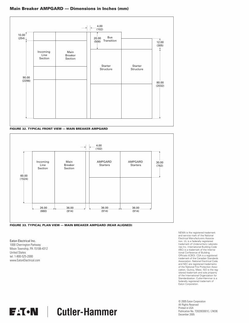
Eaton Electrical Inc.1000 Cherrington ParkwayMoon Township, PA 15108-4312United Statestel: 1-800-525-2000www.EatonElectrical.com
© 2005 Eaton CorporationAll Rights ReservedPrinted in USAPublication No. TD02003001E / Z4036December 2005
Main Breaker AMPGARD — Dimensions in Inches (mm)
FIGURE 32. TYPICAL FRONT VIEW — MAIN BREAKER AMPGARD
FIGURE 33. TYPICAL PLAN VIEW — MAIN BREAKER AMPGARD (REAR ALIGNED)
10.00 (254)
Incoming Line
Section
Main Breaker Section
Bus Transition
20.00 (508)
Starter Structure
Starter Structure
12.00 (305)
80.00 (2032)
90.00 (2286)
4.00 (102)
60.00 (1524)
Incoming Line
Section
Main Breaker Section
AMPGARD Starters
AMPGARD Starters
30.00(762)
36.00 (914)
36.00 (914)
36.00 (914)
26.00 (660)
4.00 (102)
NEMA is the registered trademark and service mark of the National Electrical Manufacturers Associa-tion. UL is a federally registered trademark of Underwriters Laborato-ries Inc. International Building Code (IBC) is a trademark of the Interna-tional Conference of Building Officials (ICBO). CSA is a registered trademark of the Canadian Standards Association. National Electrical Code and NEC are registered trademarks of the National Fire Protection Asso-ciation, Quincy, Mass. ISO is the reg-istered trademark and sole property of the International Organization for Standardization. Cutler-Hammer is a federally registered trademark of Eaton Corporation.