motor control: using the variable frequency drive, plc and ......motor control: using the variable...
TRANSCRIPT

Motor Control: Using the Variable Frequency Drive, PLC and HMI
17 of 58
Section 2: Programming The VFD With Connected Components
Workbench (CCW)
Before you begin
About this lab
In the previous lab we started, operated and did some minor parameter changes to the VFD via the Keypad.
While many applications use this form of setup and operation it can be somewhat cumbersome to configure and operate the
700 plus parameters in the VFD all through the Keypad.
The following section will show you how to use Connected Components Workbench software (CCW) to connect to and
configure the VFD for local operational control (at the Keypad), but eventually for PLC control and then (Section 3) for HMI
control.
This section will walk you through the steps to program and operate the VFD and its motor all through CCW.
Never under any circumstances remove or tamper with any of the covers of the VFD or Motor- or expose any
wiring!
Tools & Prerequisites
Tools
Material
• The PoweFlex 520 User Manual (520-um001) located in the same directory as this lab document.
Software programs required
The following software is required to complete this lab.
• Connected Components Workbench (CCW)
Hardware devices required
The following hardware is required for this lab.
• PowerFlex 525 Variable Frequency Drive (VFD)
• Motor connected to the VFD
• VFD and PC EtherNet cable plugged into the EtherNet Switch
Prerequisites
Understanding of the Rockwell Automation Connected Components Workbench (CCW) Software.
Attending the lecture entitled “VFD basic fundamentals”
Completing part 1 of this 3 part lab, Become familiar with the VFD Keypad

Motor Control: Using the Variable Frequency Drive, PLC and HMI
18 of 58
NOTE: The first three set
of numbers for the IP
address will be the same
for the Computer, PLC,
HMI, and VFD Motor; the
fourth number should be
different
Typical Industry will
follow the following
standard
4th Number of IP
Address will be set within
the range below
Computer/PLC: 1-10
HMI: 11-20
VFD: 21-30
Network Configuration for this part of the Lab:
NOTE: Ethernet Wire Color DOES NOT matter.
PanelView 800 2711 R - T7T or 2711 - T6T
EtherNet/IP Switch Stratix 2000
( no IP Address )
Micro85 0 PLC
Main Drive VFD
De sktop PC Check IP Address
from Computer
To: PLC
To: HMI
To: VFD
To: Computer
To: Ethernet
Wall Connection
UNMANGED
SWITCH

Motor Control: Using the Variable Frequency Drive, PLC and HMI
19 of 58
2.1 Setting Device IP Addresses
In order for CCW on your PC to communicate with the VFD, we first need to set up the Ethernet/IP
addresses in the VFD, AND we need to be sure your PC has an IP address within the same subnet.
Check IP Address of the computer: Start Menu (Bottom Right Corner) > Type Command Prompt >
Select Command Prompt
Type ipconfig > Write down the IPv4 Address and Sub-Net Mask Address
NOTE: These addresses are unique to the computer. (The addresses show are for the teacher’s
computer)
Windows Operating Systems may vary, but this is typically done via the PC’s Local Area Connection or
EtherNet port Configuration

Motor Control: Using the Variable Frequency Drive, PLC and HMI
20 of 58
Setting Static IP Address for the computer
Start Menu > Type Ethernet > Select Change Ethernet Settings
Select Change Adapter Options

Motor Control: Using the Variable Frequency Drive, PLC and HMI
21 of 58
Select Ethernet Icon > Right Click > Select Properties
NOTE: Computer may prompt for Administrator Login > Have Teacher login in with their credentials
Select Internet Protocol Version (TCP/IPv4) >Properties
Select > Properties

Motor Control: Using the Variable Frequency Drive, PLC and HMI
22 of 58
Select Use the Following IP Address (Input IPv4 address from the Ipconfig step above)
NOTE: The first three set of numbers for the IP address will be the same for the Computer, PLC, HMI,
and VFD Motor; the fourth number should be different
Typical Industry will follow the following standard
4th Number of IP Address will be set within the range below
Computer/PLC: 1-10
HMI: 11-20
VFD: 21-30

Motor Control: Using the Variable Frequency Drive, PLC and HMI
23 of 58
Power up the VFD.
In order for the CCW and the PC to connect to the VFD via Ethernet, once the PC’s IP is set we need to
set the IP address and Subnet Mask on the VFD to
IPv4 Address Use Student Computer
Mask Use Student Computer
From what you learned in Section 1 about changing the VFD’s parameters on the Keypad- set the
following.
(Refer back to Tutorial1: VFD and Powerflex Interface Tutorial for reference to the Keypad symbols)
In the Communication Parameters Enter the Following (Use IP Address IPv4 from Ipconfig step and
make sure the 4th number set is different than the computer: Since this is the VFD make it a number
between 21-30)
Parameter Description Enter
C128 Enable Address Select 1
C129 IP address 4th Octet #.x.y.z 21
C130 IP address 3rd Octet x.#.y.z 14
C131 IP address 2nd Octet x.y.#.z 56
C132 IP address 1st Octet x.y.z.# 10
C133 Subnet Mask 4th Octet #.x.y.z 255
C134 Subnet Mask 3rd Octet x.#.y.z 255
C135 Subnet Mask 2nd Octet x.y.#.z 252
C136 Subnet Mask 1st Octet x.y.z.# 0
The VFD must now be power cycled.
Turn off power to the VFD.
Allow enough ‘power off’ time for the KEYPAD to discharge and go off Return power to the VFD
STOP: Check to see if IP Address and Subnet Mask is set in CCW and HMI
Example IP Setup from teachers Computer:
CCW: 10.56.14.1
HMI: 10.56.14.11
VFD: 10.56.14.21

Motor Control: Using the Variable Frequency Drive, PLC and HMI
24 of 58
2.2 Verifying the EtherNet Network using RSLinx
One of the biggest challenges in getting devices to communicate to each other over any Network is
knowing if the Network is functioning correctly and if the device are connected to it.
There are many types of networks and many different protocols (think of hardwired Ethernet, Serial
RS232, DF422…wireless- WiFi, Bluetooth, inferred…. MIMO, SSID, WEP-EAP-WPA2….)
How do you troubleshoot a device on a network system if you can’t communicate to the device?
There are industry standard protocols for hardwired devices that are straight forward (RS232, USB for
example). But when it comes to complex networks with various protocols and configurations- you need
to have something to analyze, diagnose and possibly configure the network if you can’t communicate
over it.
While there can be various methods to look ‘inside’ a network- Rockwell has a software utility that
makes it very easy- its called RSLinx Classic. It runs in the background as soon as you launch and
connect to any Rockwell product (or others) and serves as the Gateway for the devices to connect on
the Network.
For this lab we’ll be using the Ethernet/IP protocol.
IP (or CIP) means Common Industrial Protocol and is an industry standard that suppliers use to
communicate to theirs and other devices.
EtherNet/IP is somewhat similar to your Ethernet at home with the exception that the protocol has been
altered for the data collection of manufacturing automation applications – control, safety,
synchronization, motion, configuration and information.
To verify the integrity of your network and configuration of the devices on the network:
If you have not opened CCW and connected to the PLC yet- use the following
From your PC’s Windows Start Menu;
Click on All Programs and select Rockwell Software
Select RSLinx
Select the application called RSLinxs Classic
Select Configure Driver
Motor Control: Using the Variable Frequency Drive, PLC and HMI
25 of 58
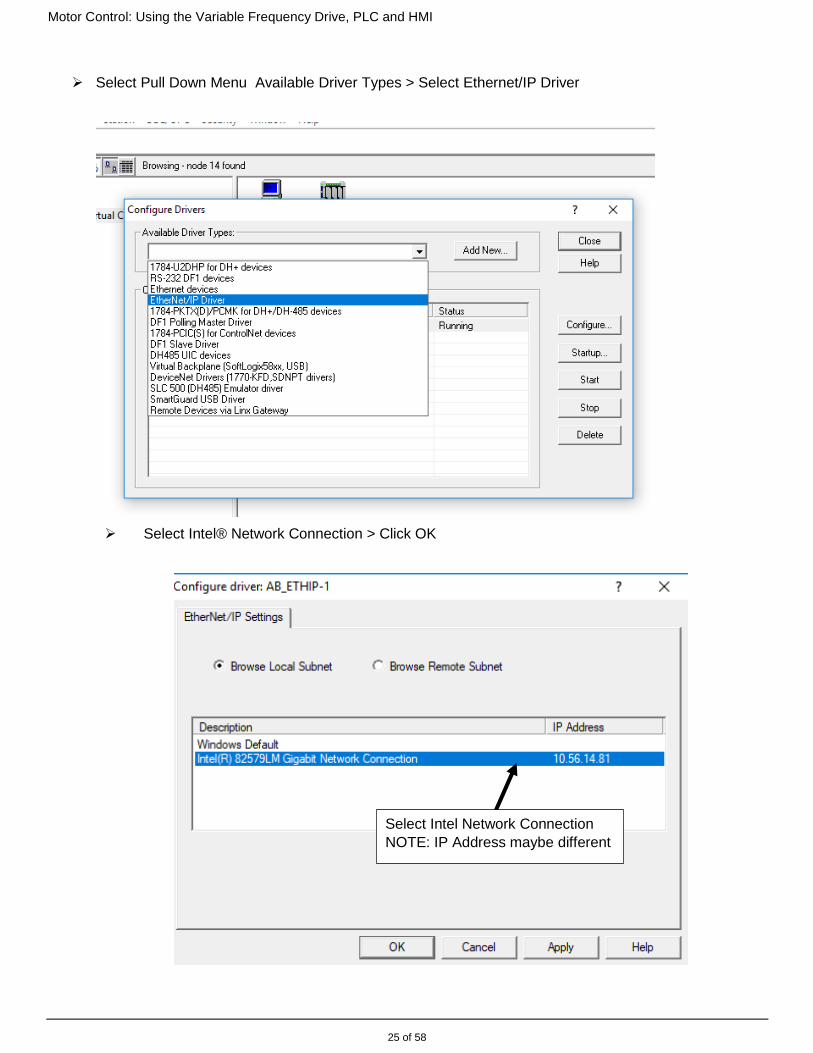
Select Pull Down Menu Available Driver Types > Select Ethernet/IP Driver
Select Intel® Network Connection > Click OK
Select Intel Network Connection
NOTE: IP Address maybe different

Motor Control: Using the Variable Frequency Drive, PLC and HMI
26 of 58
Select + sign next to AB_EthIP-1, Ethernet > The PLC, Powerflex and HMI if it is the T7T model
should show up if the Ethernet cords are plugged in and powered up thru the unmanaged switch
HMI T6T will not show up
on list
HMI T7T will show up on
the list

Motor Control: Using the Variable Frequency Drive, PLC and HMI
27 of 58
Click the icon labeled AB_ETHIP-1, Ethernet
The Network connected to your PC’s EtherNet Port will be displayed as well as all devices that are
correctly addressed and ‘on-line’. (This snapshot also shows a M850 configured and on the Network).
If a device was never configured, it would never show up here. Or if the device was at one time on the
Network but is not now, it will be displayed with a red X on it. Meaning communications to the device that was
there has failed for some reason.
Note: the PanelViewR-T7T when connected will show up in this network listing, (the T6T will not)
Example of a VFD that got disconnected from the Network
If you have opened CCW and connected to the PLC , RSLinx
is already running and you can find it in your system tray in the bottom right side of your PC display
Cl i ck on the C ha i n - li n ke d I co n ( R S Li n x C la ssi c wi l l a p p e a r wh en you h o v er o ve r it )
Cl i c k on the ‘ Ne t wo rk ” i co n The following s hould appear

Motor Control: Using the Variable Frequency Drive, PLC and HMI
28 of 58
NOTE: If your PC were connected to a M850 via the USB cable- the M850 would show up as a node on the
USB connection
.
The USB connection is a single device (Node) connection- not a Network.
The USB connection will only work when a PC is connected to the M850- not the PanelView800 or VFD.
As you continue on with M850, PanelView800-T7T and VFD labs- remember RSLinx. It is the Network trouble
shooting application.
Industry wise- this network would sow all the PLC’s, VFD’s and a host of other devices on a system line as
each PLC would be controlling multiple device and passing data to & from other PLC’s.

Motor Control: Using the Variable Frequency Drive, PLC and HMI
29 of 58
2.3 Connecting with Connected Components Software (CCW) to the VFD
Be sure your PC and VFD are all powered up and connected to the EtherNet Switch.
(the M850 PLC and/or PanelView800 do not have to be connected for this section)
Open up a new session of CCW
In the Project selection area of CCW’s startup page select Discover
RSLinx will launch your Connection Browser showing the available Networks

Motor Control: Using the Variable Frequency Drive, PLC and HMI
30 of 58
Click on the AB_ETHIP-1, Ethernet Network connection to expand the Node display of devices on that
network.
If the IP addresses you set are correct, and all devices that are powered up and plugged into the Network
Switch should be displayed as a Node on your ENet network listing as shown. (Your PanelView800 and
Micro850 may or may not be on the Node List).
Highlight the PowerFlex 525 node and select OK
Your screen should now show that you are connected to the PowerFlex VFD via CCW and will display
some of the basic status of the VFD.
Note: in the up the upper the right hand corner it indicates if you are Connected and On-line to the VFD,
or Disconnected and Off-line.
Also- in the upper right hand corner you’ll see icons referencing Manual and Help.
If you don’t already have the User Manual for the FVD open, you can open CCW’s copy of it from here.

Motor Control: Using the Variable Frequency Drive, PLC and HMI
31 of 58
The VFD configuration display is broken up as follows;
Before we continue- while watching this CCW display-
On the VFD Keypad, press START and vary the SPEED POT. Notice what the CCW VFD Status and
Feedback displays show.
You’ll notice that as you START and vary
the SPEED POT of the VFD, its Status is
displayed in CCW.
This is because you are currently
connected to the VFD while operating it via
the Keypad, and CCW is showing you the
VFD’s Status
Next, click on the pull-down icon located in the
Status window
This displays an Extended Status of the VFD.
START/STOP and adjust the
SPEED on the VFD Keypad while monitoring
this window.
This is very helpful when starting up a VFD or for debug.
VFD configuration, status and operation short cut bar VFD configuration, status and operation short cut bar
User Name of this VFD node in this CCW Project. If a M850 PLC is also part of this project it could be controlling this VFD - or multiple VFDs. - or - This project could be used as an archive file of just this 1
VFD, or several VFD’s. Basic VFD into and status Basic VFD into and status

Motor Control: Using the Variable Frequency Drive, PLC and HMI
32 of 58
Close this Extended Status display.
2.4 Uploading the VFD Parameters
Before we continue, let’s upload, name and save what the Parameters currently are in this VFD.
In the Shortcut bar of the PowerFlex 525, select Upload
The following will be displayed
This is a very important notification:
Its asking if this is the correct IP Node to upload from AND asking if you want to upload all data currently IN the
VFD AND OVERWRITE the current parameter data IN this active CCW project.
It is not critical for these labs, but CCW wants to verify that you really intend to Upload or Download to this
target device and/or overwrite the VFD saved in the Project. The reason for this is to prevent accidental
overwriting of VFD data either in the Off-line or On-line files or into the VFD itself.
For now- click on Upload Entire Device
A window will appear while the upload is proceeding. It may or may not close automatically when
finished. Close the Uploading window if it’s still open.
Next, since the parameters were uploaded are all factory default values (except for the IP address we
set in Section 2.1 and any changes to the Accel/Decel rates in Section 1.4) lets rename this VFD to
PowerFlex_1_Defaults
In the Project Organizer, rename the VFD to
PowerFlex_1_Defaults
Then under the File pull-down of CCW- select ‘Save Project As’- and save it as
PowerFlex_1_Defaults

Motor Control: Using the Variable Frequency Drive, PLC and HMI
33 of 58
Click Yes if asked to Upload Online Devices
And click Yes when it asks you again
This is because CCW wants to make sure you really want to overwrite the Offline file
Once ‘Save Project As ‘is complete CCW redisplays the Project screen, but the VFD Display page has closed
out.
In the Project Organizer, click on the VFD called PowerFlex_1_Defaults
Notice: CCW is Off-Line to the VFD
(There is nothing displayed in the VFD Status Display and in the upper right corner says its Disconnected)
All we’ve done here is simulate the following practice:
Your Supervisor (or Customer) has asked you to change the functionality of a VFD that runs a beverage can
filling machine that currently fills and caps 820 cans per minute.
What he wants you to do is change the Decel rate from 13.12 sec. to 14,27, the Acc rate from 17.34 to 17.01
and the Speed Ratio setting (Parameter A572) that changes the scaling factor of the Speed Command by just
1% in order to fine tune the system.
It’s a good practice to always save the original before editing.
In the Automation Industry, they may only allow you 5 minutes to take this system off line to make this change.
(that’s a production loss of 4,100 cans or 341.6 12 pack cases).
If you didn’t write down or make and saved a copy of the original settings, if a mistake is made or the Customer
wants to revert back the original data, you’ll most likely exceed the 5 minute window you were given trying to
remember the original values and Parameter numbers and/or mistakes can happen which could cause a 5 min
fix into a catastrophe for a few day.

Motor Control: Using the Variable Frequency Drive, PLC and HMI
34 of 58
When you’re about to change the functionality or control of an Automated System- always make a copy of the
original before edits get made.
2.5 CCW’s VFD Shortcut Buttons, Parameter Edits and VFD control
In the Off-Line mode, notice the shortcut buttons of the PowerFlex VFD only show the following.
In the upper Right corner of the display, select the Connect button to go On-line to the VFD again.
Notice the shortcut buttons change:
Only look at the following- make NO EDITS at this time (we’ll get into more details later)
Download/Upload: Self explanatory
Compare: For comparing parameters from one VFD to another. i.e. we could use this to compare an
Off-line VFD’s parameters to that of an On-Line VFD, or between 2 Off-line VFD
Projects.
Parameters: List of all parameters or by function or by grouped parameters
The pull down under Group will allow you to look at certain ‘groups’ of
Parameters.
Properties: This shortcut displays information about the VFD as it was when we uploaded it.
Setup displays the VFD type and firmware level. DO NOT CHANGE ANYTHING
(Any Off-line changes to the type or revision of the VFD will then not load to the VFD if it’s a
mismatch)
Communication displays the IP address settings that we manually set in step Section
2.1 DO NOT CHANGE ANYTHING
(Changing the IP address will prevent communications to the VFD as this lab progresses)
Wizards: Easy to use & configure shortcuts to only the parameters we need.
Control Bar: Allows you to START/STOP & control the VFD from CCW (used in testing and
debug)
Faults: Will display live fault status of the VFD while On-line.
Reset: Resets the VFD if it is in a faulted state, (only if the fault is no longer present).

Motor Control: Using the Variable Frequency Drive, PLC and HMI
35 of 58
So let’s look into changing some things
PARAMETERS
Select Parameters
This VFD has 724 parameters. To make things easier, there is a
‘group’ selector pull-down in the upper left corner.
Click on it and select the group called Basic Program
By selecting Basic Program we’ll see only the group of Parameters we’re
interested in at his time.
Look at Parameters #46 and #47; START Source 1 and SPEED Reference 1
Notice they are set at Keypad and Drive Pot.
This means that the VFD will only START and accept a SPEED Ref from the controls on the Keypad, (when
not using hardwired DigInputs 02 through 08 as terminal connections to change the source to Source 2 or
Source 3.
(Ref the VFD User Manual pg 43- Control I/O Wiring Terminal Block, Control I/O Terminal Designations
Parameters #t062-t068)
Change the START Source from Keypad to EtherNet/IP
Change SPEED Reference 1 from Drive Pot to EtherNet/IP
Close the Parameters window.
Motor Control: Using the Variable Frequency Drive, PLC and HMI
36 of 58
Control Bar:
The Control Bar will allow us to operate the VFD from CCW.
However- since CCW will communicate to the VFD via Enet, had we not just changed the START and
SPEED from Keypad and Drive Pot- to EtherNet/IP- the Control Bar wouldn’t have been able to run the
VFD.
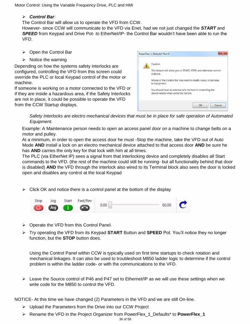
Open the Control Bar
Notice the warning
Depending on how the systems safety interlocks are
configured, controlling the VFD from this screen could
override the PLC or local Keypad control of the motor or
machine.
If someone is working on a motor connected to the VFD or
if they are inside a hazardous area, if the Safety Interlocks
are not in place, it could be possible to operate the VFD
from the CCW Startup displays.
Safety Interlocks are electro mechanical devices that must be in place for safe operation of Automated
Equipment.
Example: A Maintenance person needs to open an access panel door on a machine to change belts on a
motor and pulley.
At a minimum, in order to open the access door he must -Stop the machine, take the VFD out of Auto
Mode AND install a lock on an electro mechanical device attached to that access door AND be sure he
has AND carries the only key for that lock with him at all times.
The PLC (via EtherNet IP) sees a signal from that interlocking device and completely disables all Start
commands to the VFD. (the rest of the machine could still be running- but all functionality behind that door
is disabled) AND the VFD through the interlock also wired to its Terminal block also sees the door is locked
open and disables any control at the local Keypad
Click OK and notice there is a control panel at the bottom of the display
Operate the VFD from this Control Panel.
Try operating the VFD from its Keypad START Button and SPEED Pot. You’ll notice they no longer
function, but the STOP button does.
Using the Control Panel within CCW is typically used on first time startups to check rotation and
mechanical linkages. It can also be used to troubleshoot M850 ladder logic to determine if the control
problem is within the ladder code- or with the communications to the VFD.
Leave the Source control of P46 and P47 set to Ethernet/IP as we will use these settings when we
write code for the M850 to control the VFD.
NOTICE- At this time we have changed (2) Parameters in the VFD and we are still On-line.
Upload the Parameters from the Drive into our CCW Project
Rename the VFD in the Project Organizer from PowerFlex_1_Defaults* to PowerFlex_1

Motor Control: Using the Variable Frequency Drive, PLC and HMI
37 of 58
Save the CCW Project by clicking on File- ‘Save Project As’ and save as PowerFlex_1
You now have (2) CCW Projects of the Parameters of the VFD. (1) with Defaults- and this copy with recent
edits. If anything goes wrong and you need to start over- the Default file will have the correct parameters for
basic startup / start over of this VFD.
It’s always good practice to save as you go. A good rule of thumb; Make a Project change, do a Project save.
After preforming the ‘Save Project As’…Reopen the VFD display by clicking on the PowerFlex_1 as
listed in the Project Organizer and click on Connect.
Stop the VFD if it’s still running.
2.6 Using the CCW Wizard to Setup and Tune the VFD for a specific
application
VFD’s are very versatile and can operate anything from a garage door opener to a highly sophisticated
centrifuge or turbine. Over the years the basic setup parameters for a specific application haven’t changed.
What has changed is the VFD’s ability to work with any application or function. All we need to do is configure
the VFD for the specific application, how we want to control it and what signals or data we want it to provide
back. Then tune the VFD/Motor specifically to the application.
That’s found in the Startup Wizard tab
If you aren’t already On-line and connected to the VFD, open your CCW Project, click on
PowerFlex_1 in the Project Organizer, then click on Connect.
Then Click on Wizards.
A window will pop up showing various
Wizards Select the PowerFlex 525 Startup
Wizard
You’ll notice it uploads a group of parameters then displays the following Startup Wizard display.

Motor Control: Using the Variable Frequency Drive, PLC and HMI
38 of 58
If there are any red ! shown, that means there’s a conflicting parameter set. We’ll get to those as we proceed.
Go through the Wizard list
Reference the PoweFlex User Manual for detailed information on these settings if you have questions.
Note: There is a lot here- and too many screen snapshots to add to this document.
Each item will have a definition, but only those important to this lab will be discussed in detail.
ONLY make changes or preform the requested function where you see the instruction to EDIT or TEST.
Welcome Basic Intro
Reset Parameters Resets VFD Parameters as described.
Language Drive language setting
Motor Control EDIT The Motor Control settings configure how the VFD is to handle the
attached Motor and are specific to the Motor and application.
For this lab- set ONLY the following as follows
Torq Pref Mode: to V/Hz
Max Voltage at 230
What this does is puts the VFD in a Torque ref of Volts per Hertz. (Amount of Volts to the Motor per 1Hz of
Speed Ref).
i.e. 230 Volts DC on the Motor windings at 60Hz is 230/60 = 3.83vdc per 1hz of speed ref.
Remember: Speed is governed by the Voltage & Frequency as the magnets on the rotor of the motor are
pulled by the changing +/- polarity of the AC sinusoidal voltage on the motor windings.
Power (current or torque) required to maintain speed will be available from the VFD if needed. If the motor
demands more torque (current) for an increasing load- the width of the PWM signals will get wider- longer DC
pulses on the windings to create more ‘pulling’ torque on the rotor.

Motor Control: Using the Variable Frequency Drive, PLC and HMI
39 of 58
Motor Data EDIT Programs the Motor specs to the VFD.
This is critical for proper operation of the Motor as the VFD needs to know
the specs of the Motor.
Enter the following data. This is the Motor Nameplate Data of the motor you have connected.
IMPORTANT Note: So, we’ve been talking about the VFD runs in Volts per Hertz…and that there will be
3.83Volts per 1Hz of commanded speed (230v to the motor at 60Hz, 230/60= 3.83v/Hz)
But what’s the actual RPM of the motor at a specific command speed frequency?
The Motor nameplate data tells us that ratio.
1600 max RPM / 60hz Max frequency= 26.66 RPM for every 1Hz of commanded speed reference So,
a 10Hz Command Speed Ref would rotate the motor at 266.66 RPM.
If I want that motor to turn specifically at 525 RPM, that would be (525RPM / 26.66 RPM(per HZ) = 19.7Hz
But what is rotation? What is this motor doing? - Well, what’s it connected to??
If connected to a
Fan We’d need to know the specs of the fan- the volume of air at a set speed (RPM of the fan) Pump
What is the volume output of the pump at a set RPM
Conveyor Belt What is the gear ratio (or belt ratio) between the motor and conveyor wheel, and 1RPM of the
conveyor drive shaft equals now much linear distance?
Linear travel On a table or linear slide. The motor would be connected to a screw (ball screw) and a nut
would be on that screw and welded to the table.
If the screw had a pitch of ¼ inch then 4 revolutions of the screw equals 1”.
If we want the table to move at 50”/min we would calculate the Command frequency to be:
Since 1600 RPM = 60hz
1600 RPM / 4Revs of the screw per inch = 400 IPM max linear speed at 60Hz max command freq.
400 IPM / 60Hz = 6.666 IPM” per 1Hz.
Desired linear speed is 50 IPM, so 50 IPM / 6.66”per 1Hz = 7.50Hz of commanded freq to achieve 50 IPM
linear speed.
Lets double check that:
Max IPM is 400, divide that by our desired speed of 50 IPM = 8 (50 IPM is 1/8th the Max IPM)
Since 50 IPM is at 7.5Hz, if we multiply both by 8, that validates that we’ll be at 400 IPM at 60Hz.
Feedback Only used if a positioning or speed feedback device were attached.
Think of your car sitting on ice- you have your foot to the floor and your speedometer reads that your
speed is 110 MPH and you’ve traveled 1.2 miles- But you’re standing still on the ice and haven’t gone
anywhere.
That’s because the speedometer & odometer are tied into the transmission of the car and are telling
you what the command speed is to the wheels and the distance traveled is from the expected distance
per 1 rev of the car’s tires. The feedback (Velocity & Distance) is not actually tied to the surface contact
of the wheel

Motor Control: Using the Variable Frequency Drive, PLC and HMI
40 of 58
A Quadrature Encoder is an example of a simple feedback device that basically produces (x) amount of
digital pulses per 1 revolution. For example 1,024 5vdc pulses /1 rev and a Marker on the encoder
resets that count every revolution.
Speed Feedback typically ties the Encoder back to the drive to tell it what the actual speed is of the
device the motor is connected to. (referenced to as Closing the Velocity Loop).
Closing the Velocity Loop means the drive can monitor the speed of the device attached to
the motor and keep it at the commanded speed based on the Encoders pulses per rev it reads back.
(i.e. for every 1RPM command the drive should see 1024 Pulses per Min (PPM) back from the end
device).
• If the drive sees the end device is not traveling as fast as its being commanded (wrong
expected PPM vs RPM command) it will self-adjust its PWM Freq output (# of PWM pulses) to
get that end device to the correct speed.
• If the freq output increases and yet the speed hasn’t picked up than an increased load must be
the reason for the reduced speed. If this happens the PWM frequency pulses become wider
providing more torque to the motor to get that end device to the correct speed.
With Speed Feedback the desired effect is to know what the speed of the device connected to the
motor actually is- not what the motor speed is.
Position Feedback typically ties the Encoder back to the PLC if we are concerned about the position
of the end device. (referenced as Closing the Position Loop)
Closing the Position Loop would refer to a PLC controlled system that requires to move a
certain distance and stop, (called Point to Point Programming).
If a PLC commands a speed of 50 IPM and to move only 10”:
The Closed Velocity Loop to the drive will make the drive maintain the commanded speed.
The Closed Position Loop back to the PLC would accumulate the Encoder pulses (1024/rev or
4,096/inch based on 4 revs = 1”), and know the end device has actually mover 10” after its counted
40,096 pulses and stop (0) the Command Speed.
.
Stop/Brake Mode Only used to change how the VFD decelerates or brakes to a stop.
Directional Test TEST This tests the polarity of rotation based off of a FORWARD command.
As the programmer you would check with the Mechanical Eng. to define the names of
direction, and if those directions are defined as forward or reverse.
i.e. Is clockwise motor shaft rotation to be called “forward” or “reverse”,
“up” or “down, “in” or “out” direction for the system?
This page lets you test the direction the motor will turn when given the FORWARD command.
(Notice the warnings on this page).
Enter in a reference speed and click on the Start icon
At this point (in the real world) you’d look at the rotation of the motor and determine if you want this
‘Forward” command to rotate in this direction.

Motor Control: Using the Variable Frequency Drive, PLC and HMI
41 of 58
If it’s what you want than simple click Yes
Try it and see what happens when you check the box that the rotation was not correct.
(but DO NOT change the Motor wiring)
Check the Yes box on the direction correct question before proceeding.
Auto Tune TEST Auto Tune fine-tunes the VFD to the characteristics of the Motor. Read
the procedure and tune.
Ramp Rates Used to set the Acceleration, Deceleration and ‘S’ curve.
Speed Control Determines where the SPEED reference is to come from.
Often, when a system is in Auto Mode the SPEED Ref comes from the PLC via
EtherNet. But if the system goes into Manual Control the SPEED Ref is from
another source (such as the VFD’s Speed Pot)
The (3) SPEED Ref Sources the VFD may use is determined by Digital Inputs wired to the VFD if 2 or 3
sources are required. We’ll use the default Speed Source.
Notice this Parameter Group has a red ! (you may or may not have this as well).
This indicates that there is a conflict or illegal parameter setting.
Hover over the ! to see what’s wrong (if you have one)
The same SPEED Ref Source cannot be used on multiple Speed Ref Inputs. So this is telling us that a
Source is being used more than once.
Remember in Section 2.5 we changed the START and SPEED Ref Source from Keypad to
Ethernet/IP?

Motor Control: Using the Variable Frequency Drive, PLC and HMI
42 of 58
Ethernet/IP (by Factory Defaults) was already programmed as Speed Ref 3, and in Section 2.4 we also
made Speed Ref (0) - Ethernet/IP. So that caused a conflict of the same SPEED Source being used
twice.
Go in and look at the settings on Speed Ref 3
Select 4-20mA input
Notice that the wizard shows you what terminals on the VFD to wire up the 4-20mA to.
For this lab, set Speed Ref 3 to Drive Pot while leaving the Speed Reference tab set to Ethernet/IP
Ethernet/IP Ethernet Port configuration.
There should be no changes needed here. IP address should be 192.168.1.20
and the Mask set to 255.255.255.0
Digital Inputs Determines where the Start reference is to come from.
Unlike the Speed Ref, a Start Source can come from the same source
Relay Outputs
The VFD has (2) hardwired Relay contacts that can open/close depending on the
user defined function
Opto Outputs
Similar to the Relay outputs, but optically isolated.
Analog Outputs Provides a hardwired analog output of used defined functionality- typically an
analog meter.
Pending Changes Allows you to see what you’ve changed.
Notice the changes that were made during the Auto Tune process.
Click Finish when done-
Be sure to ‘Save’ this CCW project as changes had been made.

Motor Control: Using the Variable Frequency Drive, PLC and HMI
43 of 58
Call the Saved file Tuned_VFD
You’ll be prompted to upload from the device. While your edits do reside in the project that you’re
saving, to upload from the VFD again will upload any ‘active’ data as well.
(i.e. if the drive is not running vs if it is- do you want to ‘save’ current conditions? It doesn’t matter for
this lab)
Lab Review:
You have connected to the VFD using the CCW software and found it was much easier to use than the VFD
Keypad.
This is the same software that we will be using to create our M850 Ladder Logic code to communicate and
control the VFD and we’ll be doing that with the PanelView800 HMI- which is why we had to change the
Source of where the VFD will be getting the START and SPEED Ref from.
In the next section we’ll be Importing M850 and HMI code to control the VFD with the PanelView HMI via
EtherNet.
In changing the Source inputs we discussed how there are (3) Source inputs for the START and SPEED Ref.
We also configured and tuned the VFD for the type of Motor it will be running.
In a real application, if the motor ever had to be replaced, the VFD should be re-tuned to the new motor. Even
if it’s the exact same kind of motor as characteristics of the same type of Motors can vary. Motor Name Plate
Data should only change if the new Motor has a different RPM range, Overload Current, voltage etc.
As in a normal installation startup, we operated the VFD and Motor from CCW’s Control Bar and there were
some warnings… Just like the (3) START and SPEED Source inputs that the VFD can operate from- great
care should be taken when operating a VFD from a remote source. Typically Safety Interlocks are physically
paced on the machine to prevent a remote signal from operating the VFD while the machine is in an unsafe
condition. These are typically via a Safety disable switch or input at the machine that maintenance would use
to disable all remote control of the VFD while he/she is working on it.
Your PowerFlex VFD has now been tuned to the specific characteristics of its motor and EtherNet IP has been
configured to control the Start and Speed Reference which will lead into the next section of HMI and PLC code
to control the VFD over Ethernet/IP
End of this Section
Check with the Instructor before proceeding to Section 2.