motor 3500 b cat
TRANSCRIPT

3500B EnginesApplication andInstallation Guide
4-97

1
General Information...................................................................................3General Dimension Drawings..................................................................4Support Literature......................................................................................6Electrical ........................................................................................................7Programmable Options ...........................................................................54Monitoring System Features and Capabilities.................................60Programmable Relay Control Module ................................................78Customer Communications Module ....................................................82Cooling System...........................................................................................86
Radiator Sizing .......................................................................................87Cooling Schematic .................................................................................90Aftercooler Circuit Volumes................................................................92Heat Exchanger Performance ............................................................94Aftercooler................................................................................................99
Emissions _ ISO 8179-1...........................................................................1063508B Performance.................................................................................1073512B Performance.................................................................................1273516B Performance.................................................................................147Partial List of Suppliers of Marine Controls..................................170
Table of Contents
This data contained herewith can be used for preliminary design. Before design is finalized, all data should be confirmed by your Caterpillar® dealer.
Materials and specifications are subject to change without notice.

3
General InformationThe 3500B Family of Caterpillar Engines weredesigned primarily to meet the emissionsstandards of the next century. Their cleanliness isenhanced by significantly higher ratings, betterfuel efficiency, state of the art monitoring andengine protection capability. There are severaldifferences between the 3500B and their 3500predecessors.
Mechanical Differencesbetween the 3500B and Previous3500 Engines
• Electronic control module instead of mechanicalgovernor
• Electric unit injectors with higher injectionpressures
• No Mechanical Rack Control linkage in fuelsystem
• Larger (98 mm) cam bore in cylinder block• Heavier rear gear train• Separate circuit aftercooling (with temperature
control in some applications)• The engine is self-diagnosing• Two piece, steel crown, articulated, piston with
aluminum skirt• Larger (19 in. long) air cleaners on 16 cylinder
B engines (14 in. on 3512 and 3508).• Enhanced aftercooler serviceability
Performance Differencesbetween the 3500B and Previous3500 Engines• Superior emissions• Better fuel consumption• Higher power ratings• Uses lube oil designated CF-4 or CG-4• Optimizes injection timing, throughout the
operating range• Protective power reductions when dangerous
conditions exist; overheating of exhaust or jacket water, fouled air filters, etc. ...
• Programmable, automatic cool-down
Monitoring Differences between the 3500B and Previous3500 Engines• Histograms• Logged engine events• Programmable alarms and controls
(programmable relay module)• Monitoring of engines through computer and
telephone networks (customer communications module)
Similarities between the 3500B and Previous3500 Engines• Envelope _ The basic engine is physically nearly
the same as the previous engines. Mounting isthe same.
• Connection to Driven Equipment _ the boltcircles, flywheel sizes, auxiliary drives...are all the same
• Jacket Water, Oil and Fuel Connections are inthe same location and are the same size as analogous prior 3500 Engines.
• Almost all the attachments are readily usable onprior and B engines.

4
3516B Package Gen Set with Low Fuel Consumption 123-7396
3516B Package Gen Set with Low NOx Emissions 123-3180
3508 Optional Generators 125-7852
3512 Optional Generators 125-7851
3516 Optional Generators 125-0710
3508 Prime and Continuous with FC60 Radiator 106-2090
3508 Prime with FC50 Radiator and 125-3444680 Frame Generator
3508 Prime and Continuos with 690 Frame 125-34452 Bearing Generator
3508 Standby w/FC60 and 72 Radiator with 690 125-3446Single Bearing Generator
3512 Prime, Standby & Continuos with all 108-2091Radiators and Generators
3516 Prime, Standby with 46CV Radiator and 105-2900820 2 Bearing Generators with 2 Turbos
3516 Prime, Continuos & Standby with 46CV Rad and 125-0709and 820 Single Bearing Generators with Quad Turbos
3516 Prime, Continuos & Standby w/FC72 Rad and 4P-3853820 Single Bearing Generators with Quad Turbos
3516 Prime, Continuos FC60 & 72 Radiators and 9Y-4535800 & 820 Single Bearing Generators with 2 Turbos
Market
GeneralDimension
DrawingNumber
3500B Marine Engine General Dimension Drawings(because of the volume and number of the new drawings, access the actual
drawings via the RASTAR or AutoCAD Systems)

5
3500B Marine Engine General Dimension Drawings (continued)(because of the volume and number of the new drawings, access the actual
drawings via the RASTAR or AutoCAD Systems)
3516 Prime, Continuos, and Standby with 46CV Rad and 9Y-5402820 Single Bearing Generator Twin Turbo
3516 Prime Power with Kato Generator 104-8652
3516 Standby Power with Kato Generator 100-8748
3516 Prime, Continuos & Standby FC72 Radiator 125-0708with 696 Frame Generator Quad Turbo
3512B Package Generator Set - Standby 126-5090
3512B Package Generator Set - Prime 126-5091
3508B Package Generator Set - Standby 126-5088
3508B Package Generator Set - Prime 126-5089
3516B SCAC Marine Engine - Heavy Weight 120-4499
3512B Marine Engine - Heavy Weight 115-3615
3508B Marine Engine - Heavy Weight 110-2754
3516B SCAC Marine Engine - Light Weight 125-6281
3512B Marine Engine - Light Weight 115-3610
3508B Marine Engine - Light Weight 116-8022
3516B SCAC Marine Auxiliary 125-6280
3512B Marine Auxiliary 125-6279
3508B Marine Auxiliary 125-6278
Market
GeneralDimension
DrawingNumber
6
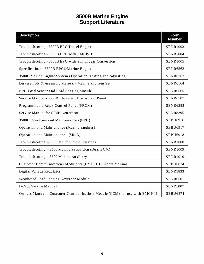
Troubleshooting - 3500B EPG Diesel Engines SENR1003
Troubleshooting - 3500B EPG with EMCP-II SENR1004
Troubleshooting - 3500B EPG with Switchgear Conversion SENR1005
Specifications - 3500B EPG&Marine Engines SENR6562
3500B Marine Engine Systems Operation, Testing and Adjusting SENR6563
Disassembly & Assembly Manual - Marine and Gen Set SENR6564
EPG Load Sensor and Load Sharing Module SENR6565
Service Manual - 3500B Electronic Instrument Panel SENR6587
Programmable Relay Control Panel (PRCM) SENR6588
Service Manual for SR4B Generator SENR8395
3500B Operation and Maintenance - (EPG) SEBU6916
Operation and Maintenance (Marine Engines) SEBU6917
Operation and Maintenance - (SR4B) SEBU6918
Troubleshooting - 3500 Marine Diesel Engines SENR1008
Troubleshooting - 3500 Marine Propulsion (Dual ECM) SENR1009
Troubleshooting - 3500 Marine Auxiliary SENR1010
Customer Communications Module for (EMCPII) Owners Manual SEBU6874
Digital Voltage Regulator SENR5833
Woodward Load Sharing Governor Module SENR6501
DeNox Service Manual SENR1007
Owners Manual - Customer Communications Module (CCM) for use with EMCP-II SEBU6874
Description FormNumber
3500B Marine Engine Support Literature

IndexParts Required ..............................................................8
Service Tools ..................................................................8
3500B Marine Propulsion Electronic Control System ...........................................9
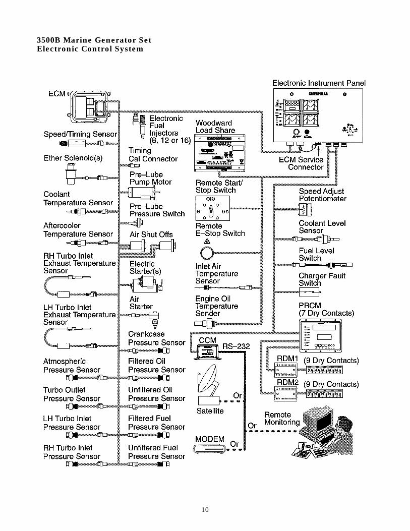
3500B Marine Generator SetElectronic Control System .........................................10
Power Supply Requirements .....................................11
Recommended Wire Size - Customer supplied.........11
Harness Wire Identification ......................................11
Electrical System Grounding Requirements ...........12
Connecting Programmable Relay Control Module(PRCM) to EIP ............................................................13
Connecting Relay & Circuit Breaker inside EIP for PRCM power control ..........................14
Connecting Programmable Relay Control Module(PRCM) to one or two Relay Driver Module(s) ........15
Connecting Relay Driver Module to Relay Board Assembly ...........................................16
Connecting to Relay Contacts on Relay Board Assembly ..........................................17
Connecting Customer Communication Module (CCM) to EIP .......................................18 & 19
Connecting Customer Communication Module (CCM) to a MODEM .....................................20
Connecting Customer Communication Module(CCM) to a Personal Computer .................................21
Connecting Customer Communication Module(CCM) to a Satellite Receiver/Transmitter ..............22
Connecting a Remote Start/Stop Switch to the EIP .....................................................................23
Connecting a Remote E-Stop Switch to the EIP .....................................................................24
Connecting a Coolant Level Sensor to the EIP .......25
Connecting a Fuel Level Switch to the EIP .............26
Marine Propulsion Only ApplicationsConnecting a 4-20 mA Converter for Throttle Input to Engine Electronic Control System .............27
Throttle and Engine Synchronization System forDual Engine control ....................................................28
Throttle and Engine Synchronization System forTriple Engine control by CENTER Throttle ............29
Throttle and Engine Synchronization System forTriple Engine control by PORT Throttle ..................31
Throttle Position Sensor Calibration ........................32
Connecting Backup Throttle Position Sensor forSingle Engine Installation .........................................33
Connecting Premium Pilot House Panel w/Switches to EIP .......................................................34
Connecting Basic Pilot House Panel w/Switches ...................................................................35
Connecting Basic Pilot House Panel w/o Switches to EIP ....................................................36
Using CCM as a CAT Data Link Signal Booster .............................................................37
Connecting a Marine Gear Oil Pressure Sensor to the EIP .....................................................................39
Connecting a Marine Gear Oil Temperature Sensor to the EIP ........................................................40
Connecting a Danfoss (or similar) Shutdown Switchto the EIP for use with PHP with Start/Stop & E-Stop Switches ..........................................................41
Generator Set Only ApplicationsConnecting a Woodward Loadshare Module to the EIP .....................................................................42
Connecting a Speed Adjust Potentiometer to the EIP .....................................................................43
Connecting an Air Temperature Sensor to the EIP .....................................................................44
Connecting an Engine Oil Temperature Sender to the EIP .....................................................................45
Connecting a Battery Charger Fault Switch to the EIP......................................................................46
Adding Circuits inside EIP for CCM Power Control...............................................................47
Connecting Customer Communication Module(CCM) to an Engine Vision Display...........................48
Wiring Diagrams / Harnesses ....................................49
Considerations in Providing Power to the3500B Engines ............................................................50
Tools for 3500B Engines - Electronic and Wiring..................................................51
7
3500B Marine Electrical

Parts RequiredThe Following chart is a reference for ordering theTOTAL parts required. Refer to the individual chartsfor the specific parts (and quantity) required for thatparticular parts installation.
Items and quantity will vary according to theinstallation options chosen.
Electronic Service ToolsThe installation requires the use ET (ElectronicTechnician) Service Tools.
1. Contact the PC hotline at 1-800-THE-PCDR (843-7237) for more information.
2. Refer to Tool Operating Manual SEHS9264, Installation anduse of the 7X-1701 Communication Adapter Tool.
3. This is a subscription, since it is anticipated that it will bechanging at regular intervals
8

9
3500B Marine PropulsionElectronic Control System
10
3500B Marine Generator SetElectronic Control System

Power Supply RequirementsThe Following chart is a reference for specifyingpower supply current requirements of eachsubsystem component. Adding up the supplyrequirements of each component will yield theTOTAL supply requirement for a given system.
Items and quantity will vary according to theinstallation options chosen.
Recommended Wire Size - Customer suppliedConsult the schematic for your application for wiresize recommendation on customer supplied wiring.The circuits breakers inside the E.l.P. are sized towork with the wire gauges shown on the schematics.
Harness Wire IdentificationThe present type of wire identification, used onCaterpillar 3500B Family of Engines, uses onlyeleven solid colors.
In addition to only eleven basic colors of wire, acircuit number is printed on each wire. The circuitnumber is printed approximately every 25 mm forthe length of the entire wire.
For example: A color code of “F702-GN” on theschematic would mean, there is a green wire withthe circuit number “F702” stamped on it. This wire isthe “Rated Speed” signal wire on the 3500B ADEM-II system wire harness. The “F702” circuitcode would be the identification of the “Rated Speed”circuit on all Caterpillar 3500B Family of Engines.
Another wire identification on the schematic is thesize of the wire. The size or gauge of the wire iscalled “AWG”. The gauge of the wire will follow thewire color.
For example: A color code of “103-RD-14” on theschematic would indicate the “103-RD” wire is a 14 AWG wire.
If the gauge of wire is not listed after the wire color,the gauge of the wire will be 18 AWG.
11

Electrical System GroundingRequirementsProper Grounding
Proper grounding for vessel and engine electricalsystems is necessary for proper performance andreliability.
NOTICEImproper grounding will cause uncontrolledand unreliable circuit paths.
This can result in damage to the engine’scrankshaft main bearings, crankshaft journalsurfaces or other engine components, and cancause electrical activity which may degradethe boat’s electronics and electrical communication equipment.
The engine’s alternator, starting motor, and ALLelectrical systems MUST be grounded to (-) Battery,and the alternator and starting motor must meetmarine Isolation requirements.
For engines which have the alternator grounded toan engine component, a ground strap MUST connectthat component to (-) Battery and the componentMUST be electrically isolated from the engine.
For engines which are utilizing the throttlesynchronization capability, it is critical that acommon ground cable be utilized between the (-)Battery connections of each engine’s battery sets.The wire should be a dedicated 00 AWG cable toensure proper synchronization operation.
Ground Plate
A ground plate with a direct path to (-) Battery ispermissible to use as a common ground point for thecomponents of one engine system.
Wire Size
The wire size of a ground plate to which analternator is grounded MUST be of adequate size tohandle full alternator charging current.
12

Connecting Programmable RelayControl Module (PRCM) to EIP
Purpose
To provide a communication link between theADEM-II/EMS-II System and the PRCM. The PRCMis used by the customer to provide 25 relay outputsand six LED outputs from eight Switch Inputs andADEM111/EMS-II System parameters. The PRCMalone controls 7 relays and 6 LED’s. For expansion,the user can add one or two Relay Driver Modules toadd an additional 9 or 18 relays. The outputs arecustomer programmable through a keypad anddisplay on the PRCM.
ValueProvides for customized warning systems using thefollowing ADEM-II/EMS-II System Parameters:
ECM Active Diagnostic PresentECM Voltage WarningEngine Oil Pressure WarningEngine Jacket Water Temperature High WarningEngine Jacket Water Temperature Low WarningEngine Overspeed WarningEngine Air Inlet Restriction WarningEngine Exhaust Temperature High WarningEngine Oil Filter Differential Pressure WarningEngine Fuel Filter Differential Pressure WarningEngine Crankcase Pressure High WarningEngine Aftercooler Temperature High WarningEngine Low Coolant Level WarningEngine Low Fuel Level WarningBattery Charger Diagnostic WarningMarine Gear Oil Temperature High WarningMarine Gear Oil Pressure Low WarningEngine Electronic Fuel Injection DisabledEngine @ 100% Load Factor (i.e. in Rack Limit)Engine Speed above 50 RPM
Engine Starter OvercrankEngine Starter Motor Relay ActiveEIP ECS Switch not in AUTO positionEngine Power Derating ActiveEngine Power Derating Active but not for AltitudeEngine ShutdownEngine Low Oil Pressure ShutdownEngine Jacket Water Temperature High ShutdownEngine Overspeed ShutdownEngine Crankcase Pressure High ShutdownEngine Aftercooler Temperature High Shutdown
Function
The operator will use the PRCM Keypad and Displaypanel to program the various input/output functions.These programmed functions will turn on/off thevarious LED’s and Relays. Refer to CaterpillarPublication SENR6588 Owner’s Manual,Programmable Relay Control Module for moredetails.
13

Connecting Relay & Circuit Breakerinside EIP for PRCM power control
Purpose
To provide a means to switch power to the PRCM viathe four position Engine Control Switch (ECS) on theengine mounted Electronic Instrument Panel (EIP).
Value
Provides on/off control of the PRCM via the ECS andshort circuit protection.
Function
The operator will install the relay, breaker andassociated wiring inside the EiP using the schematicshown above. The PRCM will be turned on via theECS in the “AUTO” (using a Remote Start/StopSwitch), “MAN.START” or “STOP” positions. ThePRCM will be turned off via the ECS in the “OFF”or”AUTO” (using a Remote Start/Stop Switch)positions.
Note: Neither the Remote E-Stop switch or the EIPmounted E-Stop Button will remove power from thePRCM. This is done to maintain relay position statusinside the PRCM in case an emergency stop is performed.
14

Connecting Programmable RelayControl Module (PCRM) to one or twoRelay Driver Modules(s)
Purpose
To provide an additional 9 or 18 relays. The outputsare customer programmable through a keypad anddisplay on the PRCM.
Value
Allows Customer to expand the number of engineparameters monitored through the PRCM.
Function
The operator will use the PRCM Keypad and Displaypanel to program the various input/output functions.These programmed functions will turn on/off theRelays. Refer to Caterpillar Publication SENR6588Owner’s Manual, Programmable Relay ControlModule for more details.
15

Connecting Relay Driver Module toRelay Board Assembly
Purpose
To provide an additional 9 or 18 relays. The outputsare customer programmable through a keypad anddisplay on the PRCM.
Value
Allows Customer to expand the number of engineparameters monitored through the PRCM.
Function
The operator will use the PRCM Keypad and Displaypanel to program the various input/output functions.These programmed functions will turn on/off theRelays. Refer to Caterpillar Publication SENR6588Owner’s Manual, Programmable Relay ControlModule for more details.
16
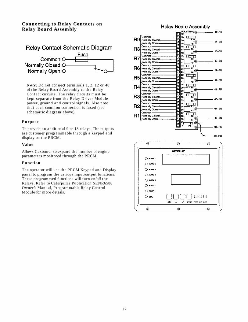
Connecting to Relay Contacts onRelay Board Assembly
Note: Do not connect terminals 1, 2, 12 or 40of the Relay Board Assembly to the RelayContact circuits. The relay circuits must bekept separate from the Relay Driver Modulepower, ground and control signals. Also notethat each common connection is fused (seeschematic diagram above).
Purpose
To provide an additional 9 or 18 relays. The outputsare customer programmable through a keypad anddisplay on the PRCM.
Value
Allows Customer to expand the number of engineparameters monitored through the PRCM.
Function
The operator will use the PRCM Keypad and Displaypanel to program the various input/output functions.These programmed functions will turn on/off theRelays. Refer to Caterpillar Publication SENR6588Owner’s Manual, Programmable Relay ControlModule for more details.
17

Connecting Customer CommunicationModule (CCM) to EIP
Purpose
To provide a two-way communication link betweenthe ADEM-II System and the Operator of a PersonalComputer or Programmable Logic Controller or otherdevice with a RS-232C Port.
Value
Allows Customer to remotely control and monitor theengine.
Function
The operator will use Caterpillar supplied “basic” PCsoftware to create Customer Specific Programs. TheCCM software can be easily upgraded via “Flash”memory programming. Refer to CaterpillarPublication SEBU6997 Owner’s Manual, CustomerCommunication Module for more details. Thefollowing is a list of parameters that can becommunicated via CCM:
Status Parameters:
1) Fault Present2) ECM Voltage Warning3) Engine Jacket Water Temp High Warning4) Engine Jacket Water Temp High Shutdown5) Engine Jacket Water Temp High Derate6) Engine Jacket Water Temp Low Warning7) Engine Oil Pressure Low Warning8) Engine Oil Pressure Low Shutdown9) Engine Oil Pressure Derate
10) Engine Overspeed Warning11) Engine Overspeed Shutdown 12) Air Inlet Restriction Warning 13) Air Inlet Restriction Derate 14) Exhaust Temperature Warning 15) Exhaust Temperature Derate 16) Oil Filter Differential Pressure Warning 17) Fuel Filter Differential Pressure Warning 18) Crankcase Pressure Warning 19) Crankcase Pressure Shutdown 20) Crankcase Pressure Derate 21) Aftercooler Water Temperature Warning 22) Aftercooler Water Temperature Shutdown 23) Aftercooler Water Temperature Derate24) Fuel Injection Disabled 25) Engine Overcrank 26) Air Shut-off Relay Active 27) Start Motor Relay Active 28) Battery Charger Fault Warning
(customer wired)29) Engine Running 30) Engine At Full Load (i.e. at rack limit)31) System not in Auto 32) High Altitude Derate 33) Low Engine Coolant Level Warning (if wired)34) Low Fuel Level Warning (if wired)35) Engine Diagnostic Active 36) Backup ECM Ready 37) Backup ECM Online 38) Marine Gear Oil Pressure Warning
(customer wired)39) Marine Gear Oil Temperature Warning
(customer wired)
18

Connecting Customer CommunicationModule (CCM) to ElP-Continued fromprevious pageOperating Parameters:
1) Engine Speed2) Instantaneous Fuel Rate3) Total Fuel Consumed4) Engine Hours5) Engine Oil Pressure6) Engine Coolant Temperature7) System Voltage8) Engine Fuel Pressure9) Exhaust Manifold Temperature
(Turbine Inlet)-RH10) Exhaust Manifold Temperature
(Turbine Inlet)-LH11) Air Inlet Restriction - RH12) Air Inlet Restriction - LH13) Fuel Filter Differential Pressure14) Oil Filter Differential Pressure15) Turbo Outlet Pressure (Boost)16) Separate Circuit Aftercooler Coolant
Temperature17) Engine Oil Temperature (GSE Only)18) Inlet Air Temperature (GSE Only)19) Marine Gear Oil Pressure (if sensor
installed/wired)20) Marine Gear Oil Temperature
(if sensor installed/wired)21) Crankcase Pressure
Control Parameters:1) Remote Start/Stop - EPG Only2) Emergency Stop- EPG Only3) Fault Reset4) Activate Idle/Rated Speed Contact
(w/EMCP 11)- EPG Only5) Activate Circuit Breaker Shunt Trip
(w/EMCP 11) - EPG Only6) Override Cooldown Timer- EPG Only
19

Connecting Customer CommunicationModule (CCM) to a Modem
Purpose
To provide a two-way communication link betweenthe CCM and a remote operator of a PersonalComputer or Programmable Logic Controller or otherdevice with a RS-232C Port.
Value
Allows Customer to remotely control and monitor theengine.
Function
The operator will use Caterpillar supplied “basic” PCsoftware to create Customer Specific Programs. TheCCM software can be easily upgraded via “Flash”memory programming. Refer to CaterpillarPublication SEBU6997 Owner’s Manual, CustomerCommunication Module for more details.
20

Connecting CustomerCommunication Module(CCM) to aPersonal Computer
Purpose
To provide a two-way communication link betweenthe CCM and an operator of a Personal Computer orProgrammable Logic Controller or other device witha RS-232C Port.
Value
Allows Customer to control and monitor the enginefrom another location in close proximity to theengine.
Function
The operator will use Caterpillar supplied “basic” PCsoftware to create Customer Specific Programs. TheCCM software can be easily upgraded via “Flash”memory programming. Refer to CaterpillarPublication SEBU6997 Owner’s Manual, CustomerCommunication Module for more details.
21
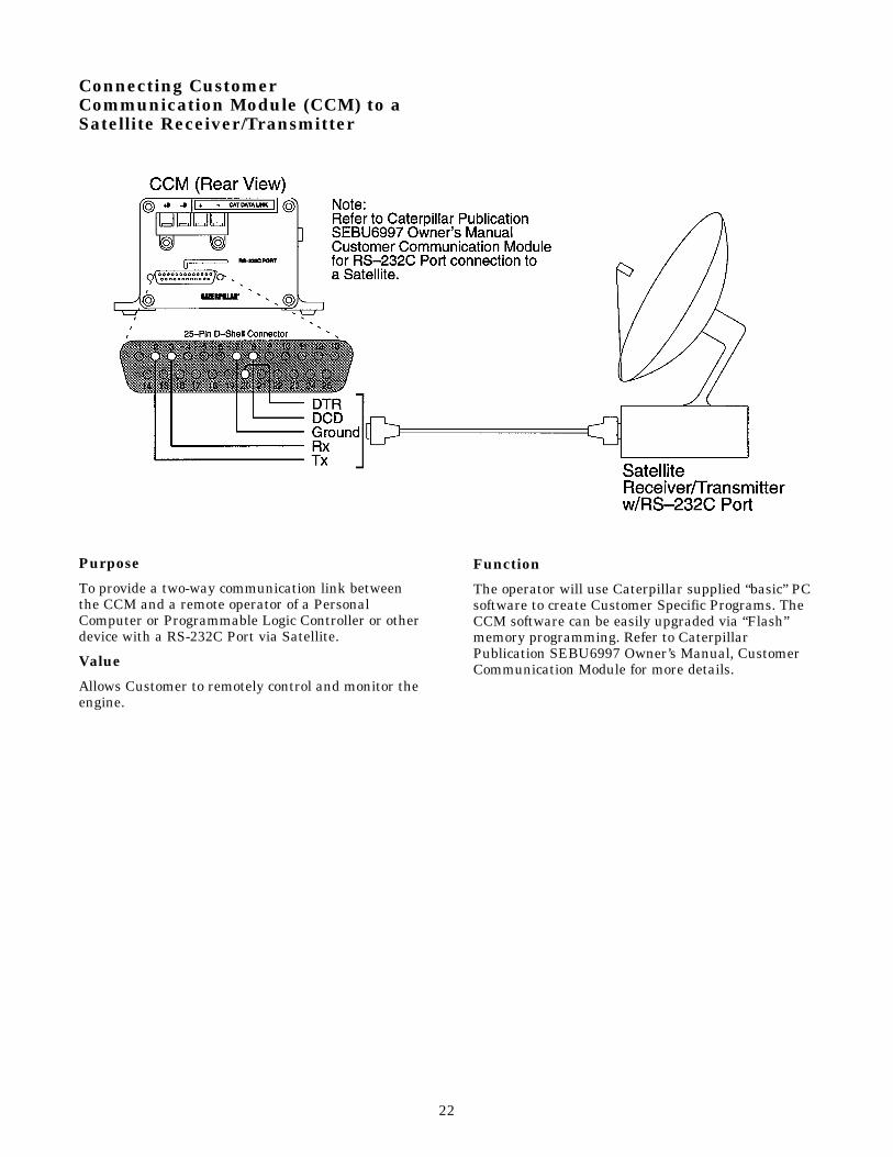
Connecting CustomerCommunication Module (CCM) to aSatellite Receiver/Transmitter
Purpose
To provide a two-way communication link betweenthe CCM and a remote operator of a PersonalComputer or Programmable Logic Controller or otherdevice with a RS-232C Port via Satellite.
Value
Allows Customer to remotely control and monitor theengine.
Function
The operator will use Caterpillar supplied “basic” PCsoftware to create Customer Specific Programs. TheCCM software can be easily upgraded via “Flash”memory programming. Refer to CaterpillarPublication SEBU6997 Owner’s Manual, CustomerCommunication Module for more details.
22
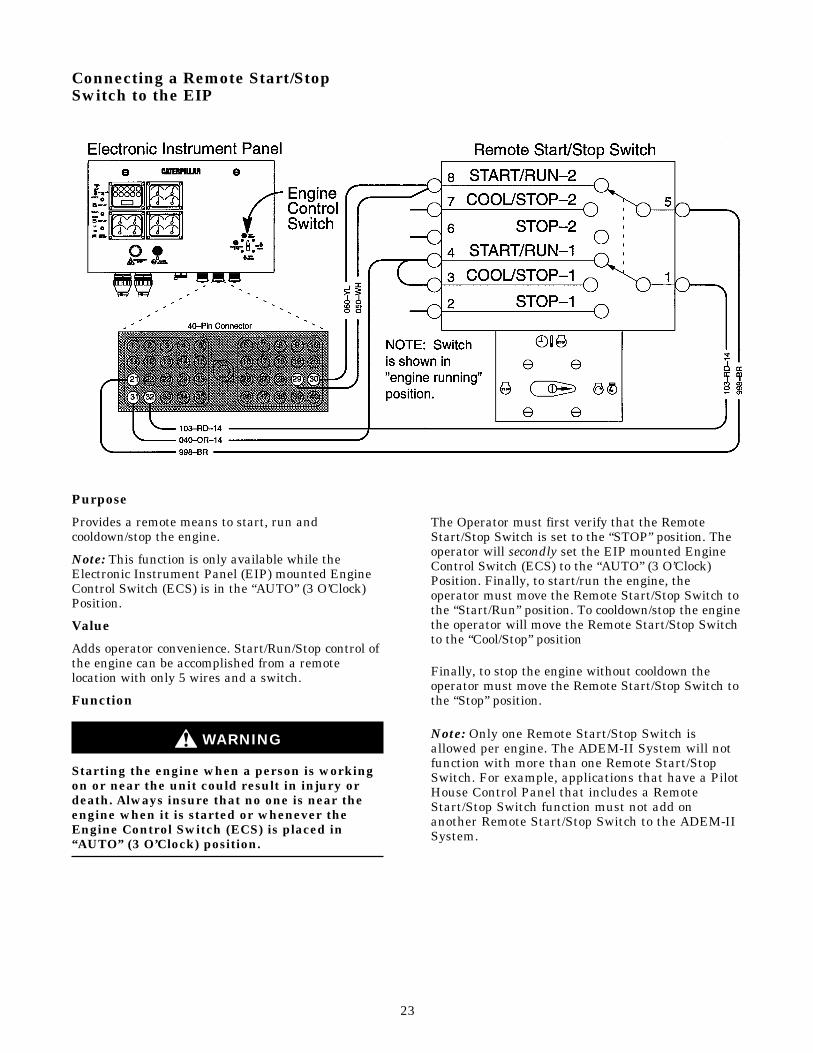
Connecting a Remote Start/StopSwitch to the EIP
Purpose
Provides a remote means to start, run andcooldown/stop the engine.
Note: This function is only available while theElectronic Instrument Panel (EIP) mounted EngineControl Switch (ECS) is in the “AUTO” (3 O’Clock)Position.
Value
Adds operator convenience. Start/Run/Stop control ofthe engine can be accomplished from a remotelocation with only 5 wires and a switch.
Function
WARNING
Starting the engine when a person is workingon or near the unit could result in injury ordeath. Always insure that no one is near theengine when it is started or whenever theEngine Control Switch (ECS) is placed in“AUTO” (3 O’Clock) position.
The Operator must first verify that the RemoteStart/Stop Switch is set to the “STOP” position. Theoperator will secondly set the EIP mounted EngineControl Switch (ECS) to the “AUTO” (3 O’Clock)Position. Finally, to start/run the engine, theoperator must move the Remote Start/Stop Switch tothe “Start/Run” position. To cooldown/stop the enginethe operator will move the Remote Start/Stop Switchto the “Cool/Stop” position
Finally, to stop the engine without cooldown theoperator must move the Remote Start/Stop Switch tothe “Stop” position.
Note: Only one Remote Start/Stop Switch isallowed per engine. The ADEM-II System will notfunction with more than one Remote Start/StopSwitch. For example, applications that have a PilotHouse Control Panel that includes a RemoteStart/Stop Switch function must not add onanother Remote Start/Stop Switch to the ADEM-IISystem.
23

Connecting a Remote E-Stop Switchto the EIP
Purpose
Provides a remote means to stop the engine.
Note: This function is available while the ElectronicInstrument Panel (EIP) mounted Engine ControlSwitch (ECS) is in the “AUTO” (3 O’Clock), “MAN.START (6 O’Clock) and “COOLDOWN STOP” (9 O’Clock) Positions.
Value
Adds operator convenience. E-Stop control of theengine can be accomplished from a remote locationwith only 3 wires and a switch.
Function
NOTICEEmergency Shutoff controls are for EMERGENCY use ONLY. DO NOT useEmergency shutoff devices or controls fornormal stopping procedure. Refer to theEngine Stopping section of CaterpillarPublication SEBU6917 for normal stoppingprocedures.
The Remote E-Stop Switch is used to shut down theengine during an emergency situation by signalingthe ECM to disable fuel injection, and actuate bothair shutoff’s if present and enabled for use via the ET Service Tool.
Note: The EIP mounted Emergency Stop pushbutton has a protective cover around it to preventinadvertent operation. Refer to SENR6587 ServiceManual, 3500B Electronic Instrument Panel formore details.
24

Connecting a Coolant Level Sensor to the EIP
Purpose
To provide a Low Coolant Level indication to theoperator.
Value
Adds a monitoring function to aid the operator inmaintaining proper coolant volume in the engine andtherefor preventing engine overheating.
Function
The operator will use the EMS-II LED correspondingto Low Coolant Level indication on the ElectronicInstrument Panel (EIP) to monitor low coolant levelin the Radiator (Gensets) or Expansion Tank(Marine). Refer to SENR6587 Service Manual, 3500BElectronic Instrument Panel for more details. Lowcoolant level will have a negative impact on enginelife.
Note: Using this Sensor, the operator can alsoreceive an Engine Low Coolant Level Warningindication via the PRCM.
25

Connecting a Fuel Level Switch to the EIP
Purpose
To provide a Low Fuel Level indication to theoperator.
Value
Aids the operator in preventing unexpected engineshutdown because of an empty fuel supply tank.
Function
The operator will use the EMS-II LED correspondingto Low Fuel Level indication on the ElectronicInstrument Panel (EIP) to monitor low fuel level inthe supply tank. Refer to SENR6587 Service Manual,3500B Electronic Instrument Panel for more details.
Note: Using this Switch, the operator can alsoreceive an Engine Low Fuel Level Warningindication via the PRCM.
26

Connecting a 4-20 mA Convertor forThrottle Input to Engine ElectronicControl System (Marine PropulsionOnly)
Purpose
Provides an isolated interface between industrystandard 4-20 mA analog input signal and theCaterpillar Standard Pulse Width Modulated format.
Value
Eliminates the need for customer to custom designpulse width modulated driver modules.
Function
Converts 4-20 mA throttle signal to CaterpillarStandard Pulse Width Modulated format.
27

Throttle and Engine SynchronizationSystem for Dual Engine control(Marine Propulsion Only)
Purpose
To link the engine controls of both engines to a singlethrottle.
Value
Adds operator convenience, vessel control and is astandard practice in marine applications.
Function
The operator will use the Synchronization Switch totransfer the control of both engines to a singlethrottle lever. The Electronic Control Module (ECM)will then control engine speed from the “Master”throttle lever. Engine synchronization can betransferred to either the PORT or STARBOARD(STBD) throttle.
The Operator will set the Synchronization Switchand then adjust the throttles to bring the enginespeeds within 50 rpm of each other. The Enginecontrols will detect if and when the engine speedsare within 50 rpm of one another and then lock ontothe “Master” throttle for engine speed control.
Note: Synchronization can only occur when bothengine speeds are within 50 rpm of each other.Likewise, unsynchronization can only occur whenboth engine speeds are within 50 rpm of each other.
28

Throttle and Engine SynchronizationSystem for Triple Engine control byCENTER Throttle (Marine PropulsionOnly)
29

Purpose
To link the engine controls of all three engines to asingle throttle.
Value
Adds operator convenience, vessel control and is astandard practice in marine applications.
Function
The operator will use the Throttle SynchronizationSwitch to transfer the control of all three engines tothe CENTER throttle lever. The Electronic ControlModule (ECM) of each engine will then governengine speed from the CENTER Engine throttlesignal.
Note: Engine synchronization can not be transferredto either the PORT or STARBOARD (STBD) throttlecontrol. Engine speeds can only be synchronized tothe CENTER throttle control.
The Operator will set the Synchronization Switchand then adjust the PORT and STARBOARDthrottles to bring their engine speeds to within 50 rpm of the CENTER engine. The Engine controlswill detect if and when the PORT and STARBOARDengine speeds are within 50 rpm of the CENTERengine and then “lock” onto the CENTER throttle forengine speed control.
Note: Synchronization can only occur when allengine speeds are within 50 rpm of one another.Likewise, unsynchronization can only occur when allengine speeds are within 50 rpm of one another.
30

Throttle and Engine SynchronizationSystem for Triple Engine control byPORT Throttle (Marine PropulsionOnly)
31

Throttle Position Sensor Calibration(Marine Propulsion Only)Inspect Throttle Linkage
Inspect the Throttle linkage for:
• Loose, bent, broken, missing, worn components.
Also, inspect for interface with the linkage or returnspring.
Throttle linkage should work smoothly withoutexcessive drag, and return to LOW IDLE positionWITHOUT assistance in less than one second.
Adjustment at Low Idle Stop Position(Minimum Throttle)
The calibration of the throttle position sensorrequires the use of an IBM PC compatible LaptopComputer “/Communication Adapter and CaterpillarET Software. Run ET and from the first screen“Click” on the “Service” pull-down menu.
• Turn ECS (Engine Control Switch) to OFFposition.
• Connect to the ECAP or ET System
• Turn ECS to “Cool Down/Stop” (9 O’clock) position.• Access the Monitor Throttle Position Sensor Signal
screen to display the Duty Cycle.
Adjust the throttle linkage, with the throttle at LOWIDLE position, until:• The Duty Cycle reading (display) is between 5%
and 10%.
Note: After adjustment, a slight movement OFF(away from) the LOW IDLE linkage stop shouldincrease the Duty Cycle reading.
When properly adjusted, the rotary disc should bepositioned as shown in Illustration 1 when thethrottle is in the LOW IDLE position.
Adjustment at High Idle Stop Position (Maximum Throttle)
Adjust the throttle linkage, with the throttle at LOWIDLE position, until:• The Duty Cycle reading (display) is between 90%
and 95%.
When properly adjusted, the rotary disc should bepositioned as shown in Illustration 2 when thethrottle is in the HIGH IDLE position.
Repeat the adjustment at LOW IDLE position toverify that the LOW IDLE stop is still properlyadjusted.
32

Connecting Backup Throttle PositionSensor for Single Engine Installation(Marine Propulsion Only)
Purpose
To provide Throttle Position Sensor redundancy.
Value
Adds operator convenience. If diagnostic problem isidentified on Primary Throttle then simply select theBackup Throttle via the Throttle Selection Switch.
Function
The operator will use a switch to transfer the controlof the engine to the Backup Throttle Position Sensor.The Electronic Control Module (ECM) will thencontrol engine speed from the Backup throttle lever.
33
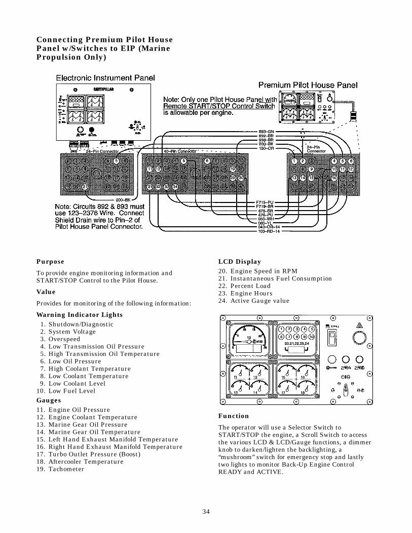
Connecting Premium Pilot HousePanel w/Switches to EIP (MarinePropulsion Only)
Purpose
To provide engine monitoring information andSTART/STOP Control to the Pilot House.
Value
Provides for monitoring of the following information:
Warning Indicator Lights1. Shutdown/Diagnostic2. System Voltage3. Overspeed4. Low Transmission Oil Pressure5. High Transmission Oil Temperature6. Low Oil Pressure7. High Coolant Temperature8. Low Coolant Temperature9. Low Coolant Level
10. Low Fuel LevelGauges11. Engine Oil Pressure12. Engine Coolant Temperature13. Marine Gear Oil Pressure14. Marine Gear Oil Temperature15. Left Hand Exhaust Manifold Temperature16. Right Hand Exhaust Manifold Temperature17. Turbo Outlet Pressure (Boost)18. Aftercooler Temperature19. Tachometer
LCD Display20. Engine Speed in RPM21. Instantaneous Fuel Consumption22. Percent Load23. Engine Hours24. Active Gauge value
Function
The operator will use a Selector Switch toSTART/STOP the engine, a Scroll Switch to accessthe various LCD & LCD/Gauge functions, a dimmerknob to darken/lighten the backlighting, a“mushroom” switch for emergency stop and lastlytwo lights to monitor Back-Up Engine ControlREADY and ACTIVE.
34

Connecting Basic Pilot House Panelw/Switches to EIP (MarinePropulsion Only)
Purpose
To provide basic engine monitoring information andSTART/STOP Control to the Pilot House.
Value
Provides for monitoring of the following information:
Warning Indicator Lights1. Shutdown/Diagnostic2. System Voltage3. Overspeed4. Low Transmission Oil Pressure5. High Transmission Oil Temperature6. Low Oil Pressure7. High Coolant Temperature8. Low Coolant Temperature9. Low Coolant Level
10. Low Fuel LevelGauges11. Engine Oil Pressure12. Engine Coolant Temperature13. Marine Gear Oil Pressure14. Marine Gear Oil Temperature15. Tachometer
LCD Display
16. Engine Speed in RPM17. Instantaneous Fuel Consumption18. Percent Load19. Engine Hours20. Active Gauge value
Function
The operator will use a Selector Switch toSTART/STOP the engine, a Scroll Switch to accessthe various LCD & LCD/Gauge functions, a dimmerknob to darken/lighten the backlighting, a“mushroom” switch for emergency stop and lastlytwo lights to monitor Back-Up Engine ControlREADY and ACTIVE.
35
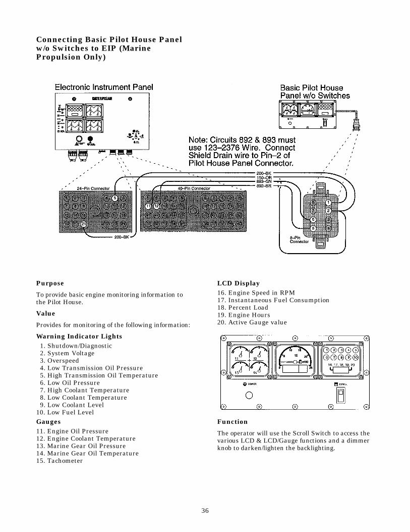
Connecting Basic Pilot House Panelw/o Switches to EIP (MarinePropulsion Only)
Purpose
To provide basic engine monitoring information tothe Pilot House.
Value
Provides for monitoring of the following information:
Warning Indicator Lights1. Shutdown/Diagnostic2. System Voltage3. Overspeed4. Low Transmission Oil Pressure5. High Transmission Oil Temperature6. Low Oil Pressure7. High Coolant Temperature8. Low Coolant Temperature9. Low Coolant Level
10. Low Fuel LevelGauges11. Engine Oil Pressure12. Engine Coolant Temperature13. Marine Gear Oil Pressure14. Marine Gear Oil Temperature15. Tachometer
LCD Display16. Engine Speed in RPM17. Instantaneous Fuel Consumption18. Percent Load19. Engine Hours20. Active Gauge value
Function
The operator will use the Scroll Switch to access thevarious LCD & LCD/Gauge functions and a dimmerknob to darken/lighten the backlighting.
36
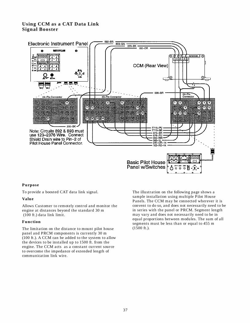
Using CCM as a CAT Data Link Signal Booster
Purpose
To provide a boosted CAT data link signal.
Value
Allows Customer to remotely control and monitor theengine at distances beyond the standard 30 m(100 ft.) data link limit.
Function
The limitation on the distance to mount pilot housepanel and PRCM components is currently 30 m(100 ft.). A CCM can be added to the system to allowthe devices to be installed up to 1500 ft. from theengine. The CCM acts as a constant current sourceto overcome the impedance of extended length ofcommunication link wire.
The illustration on the following page shows asample installation using multiple Pilot HousePanels. The CCM may be connected wherever it isconvent to do so, and does not necessarily need to bein series with the panel or PRCM. Segment lengthmay vary and does not necessarily need to be inequal proportions between modules. The sum of allsegments must be less than or equal to 455 m(1500 ft.).
37

General CCM Installation Information
When a CCM is installed, these requirements mustbe met:• The environmental, mounting, wiring, and cable
specifications must be met.
• The connections diagrams must be followed.
Specifications
• The ambient operating temperature range is from-40°C to + 70°C (-40°F to + 158°F).
• The storage temperature range is from -40°C to + 85°C (-40°F to + 185°F).
• The unit must be protected from direct contactswith liquids (splash-proof). If sealing is required,the CCM must be in a water-tight enclosure.
Mounting
The CCM should be located on a desk or shelf. Therubber feet on the bottom of the CCM can also beremoved to allow panel mounting.
Note: Do not mount the CCM on an engine or withinan engine mounted enclosure. It is not designed forthis environment.
General Wire and Cable Specifications
The following specifications for wire and cable isgiven to reduce voltage drops over long runs of wireand to reduce EMI/RFI interference.• The wires connected to B+ and B- on the CCM
must be at least 16 AWG.• Maximum CAT Data Link cable and ± B wire
length is 455 m (1500 ft.), including wire runsbetween any multiple panels.
• No terminations or splices allowed on the abovewires, except as noted in the connection diagrams.
• The cable connected to CAT Data Link ± must be16 AWG, shielded twisted pair cable. Use 123-2376 Electric Cable, Belden 8719 Cable, orequivalent.
38

Connecting a Marine Gear OilPressure Sensor to the EIP (MarinePropulsion Only)
Purpose
To provide a Marine Gear Oil Pressure indication tothe operator.
Value
Aids the operator in maintaining proper MarineGear Oil Pressure.
Function
The operator will use the EMS-II Gauges on theElectronic Instrument Panel (EIP) to monitor MarineGear Oil Pressure. Refer to SENR6587 ServiceManual, 3500B Electronic Instrument Panel formore details.
Note: Using this Sensor, the operator can alsoreceive a Marine Gear Oil Pressure Low Warningindication via the PRCM.
39

Connecting a Marine Gear OilTemperature Sensor to the EIP(Marine Propulsion Only)
Purpose
To provide a Marine Gear Oil Temperatureindication to the operator.
Value
Aids the operator in maintaining proper MarineGear Oil Temperature.
Function
The operator will use the EMS-II Gauges on theElectronic Instrument Panel (EIP) to monitor MarineGear Oil Temperature. Refer to SENR6587 ServiceManual, 3500B Electronic Instrument Panel formore details.
Note: Using this Sensor, the operator can alsoreceive a Marine Gear Oil Temperature HighWarning indication via the PRCM.
40

Connecting a Danfoss (or similar)Shutdown Switch to the EIP for usewith PHP with Start/Stop & E-StopSwitches (Marine Propulsion Only)
Purpose
Provides a means to stop the engine via a remote drycontact switch.
Value
Provides shutdown function interface for theoperator to allow the use of dry contact switches toshutdown the engine for conditions defined by theoperator for engine/vessel protection.
Function
NOTICEEmergency Shutoff controls are for EMERGENCY use ONLY. DO NOT useEmergency shutoff devices or controls fornormal stopping procedure. Refer to theEngine Stopping section of CaterpillarPublication SEBU6917 for normal stoppingprocedures.
The Shutdown Switch is used to shut down theengine during an emergency situation or condition bysignaling the ECM to disable fuel injection, andactuate both air shutoff’s if present and enabled foruse via the ET Service Tool. The marine engine ECM
monitoring system does not currently allow forengine shutdowns, except for engine overspeedshutdown.
Low oil pressure & high jacket water temperatureDanfoss contactors are available through the PriceList. However, other manufacturer switches may beutilized, as well as additional switches for otherdesired parameters.
The momentary or time delay switch serves twobasic purposes. First, it is required during start-upfor a low oil pressure switch as an override untilengine oil pressure builds up sufficiently. A timedelay of 8-9 seconds would provide acceptableperformance. Second, a momentary switch wouldprovide a means for override of any switch shutdowncondition for emergency engine operation ortroubleshooting.
If more than one shutdown switch is utilized, theswitches must be connected in series on the 99~BRwire.
This shutdown switch wiring instruction is notintended to meet Unattended Machinery Spacemarine society certification requirements. If thiscriteria must be met, please contact the factory forfurther instruction.
41

Connecting a Woodward LoadshareModule to the EIP (Generator SetsOnly)
Purpose
To provide a means of sharing load with multiplegenerator sets.
Value
Allows Woodward Loadshare Module to controlengine speed.
Function
The operator will use the Woodward LoadshareModule’s PWM OUTPUT SIGNALS (+) & (-) toprovide a “Desired Engine Speed” signal to theADEM-II ECM. Refer to SENR6587 Service Manual,3500B Electronic Instrument Panel for more details.
Note: The 9X-9591 Speed Control inside of theElectronic Instrument Panel (EIP) must be removedif present and the “F702-GN” wire connected to the“S” Terminal of the 9X-9591 must then be connectedto Pin-36 of the 40-Pin Customer Connector.
42

Connecting a Speed AdjustPotentiometer to the EIP (GeneratorSets Only)
Purpose
To provide a means of controlling engine speed onGenerator Sets using the 9X-9591 Speed Control.
Value
Allows the operator to adjust the 9X-9591 SpeedControl’s “Desired Engine Speed” Pulse WidthModulated (PWM) output signal. The 9X-9591 SpeedControl resides inside the Electronic InstrumentPanel (EIP). Refer to SENR6587 Service Manual,3500B Electronic Instrument Panel for more details.
Function
The operator will use the Speed AdjustPotentiometer to vary the “Desired Engine Speed”PWM signal’s pulse width. This signal is inputted tothe ADEM-II ECM which in turn governs “ActualEngine Speed”.
43

Connecting an Air TemperatureSensor to the EIP (Generator SetsOnly)
Purpose
To provide temperature measurement of the intakeair prior to entering the cylinder head.
Value
Aids detection of degraded aftercooler performance,and high ambient air temperatures or poor airventilation in the area immediately next to engineair filters.
Function
The operator will use the EMS-II Gauges on theElectronic Instrument Panel (EIP) to monitor inletair temperature. Refer to SENR6587 ServiceManual, 3500B Electronic Instrument Panel formore details. Temperatures 30°C greater thanAftercooler Water Temperature will have a negativeimpact on engine performance.
44
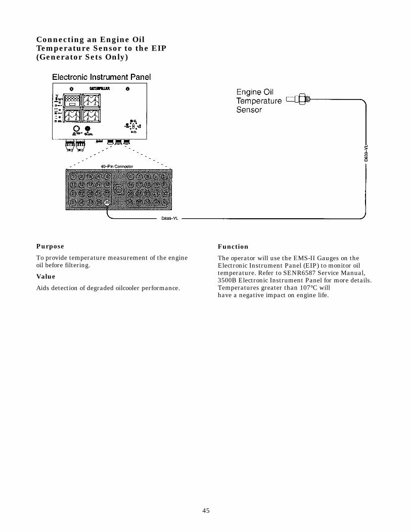
Connecting an Engine OilTemperature Sensor to the EIP(Generator Sets Only)
Purpose
To provide temperature measurement of the engineoil before filtering.
Value
Aids detection of degraded oilcooler performance.
Function
The operator will use the EMS-II Gauges on theElectronic Instrument Panel (EIP) to monitor oiltemperature. Refer to SENR6587 Service Manual,3500B Electronic Instrument Panel for more details.Temperatures greater than 107°C will have a negative impact on engine life.
45

Connecting a Battery Charger FaultSwitch to the EIP (Generator SetsOnly)
Purpose
To provide a means of indicating a failing batterycharger to the operator.
Value
Allows the operator to prevent an undesired engineshutdown caused by a battery charger failure.
Function
The operator will use the EMS-II “System Voltage”warning LED on the Electronic Instrument Panel(EIP) to monitor the battery charger. Refer toSENR6587 Service Manual, 3500B ElectronicInstrument Panel for more details. If a batterycharger failure occurs, the ADEM-II ECM willcontinue to govern the engine down to a minimumbattery voltage of 10 Volts DC.
NOTICEIf the engine has been shut down, and arestart is needed, and the battery voltage is below14.4 Volts DC with the ADEM-II system pow-ered but prior to Cranking the starters thenthe engine may not restart. This is because the ECMRelay (ECMR) inside of the ElectronicInstrument Panel (EIP) has a minimum pull-in voltage of 14.4 Volts DC. The relay’s con-tacts supply (+) Battery voltage to the ECM. If the relay contacts donot close then the ECM will not power-up.The relay’s minimum hold-in voltage is 7.0 Volts DC.
Note: Using this Switch, the operator can alsoreceive a Battery Charger Diagnostic Warningindication via the PRCM.
46

Adding circuits inside EIP for CCMpower control (Genset & MarineAuxiliary Applications ONLY)
PurposeTo provide a means to switch power to the CCM(Customer Communication Module) via the fourposition Engine Control Switch (ECS) on the enginemounted Electronic Instrument Panel (EIP).
Value
Provides on/off control of the CCM via the ECS andshort circuit protection.
Function
The operator will install the wiring inside the EIPusing the schematic shown above. The CCM will beturned on via the ECS in the “AUTO” (using aRemote Start/Stop Switch), “MAN.START” or”STOP”positions. The CCM will be turned off via the ECS inthe “OFF” or “AUTO” (using a Remote Start/StopSwitch) positions. Note: Using the Remote E-Stop switch functionwill not remove power from the CCM. Using theEIP mounted E-Stop Button will remove powerfrom the CCM.
47

Connecting CustomerCommunication Module (CCM) to anEngine Vision Display (MarinePropulsion Only)
Purpose
To provide a two-way communication link betweenthe CCM and the Engine Vision Display.
Value
Allows Customer to remotely monitor the engine.
Function
The operator will use Caterpillar supplied “basic” PCsoftware to create Customer Specific Programs. TheCCM software can be easily upgraded via “Flash”memory programming. Refer to CaterpillarPublication SEBU6874 Owner’s Manual, CustomerCommunication Module for more details.
48

49
Wiring Diagrams and Wiring GroupsUse the following information with caution, as the part numbers are subject to change.
Engine Wiring Diagram Number
Wiring DiagramForm Number
Gen Set (EMCP II)
Gen Set (engine only)
Marine Engine (Dual ECM)
Marine Auxiliary Engine (Single ECM)
121-2027
125-9744
126-7150
126-9193
SENR1004
SENR1005
SENR1009
SENR1010

50
Considerations in ProvidingElectrical Power to the 3500B Marine Engine
(Questions heard and answered during Field EngineInstallation)
What is the acceptable voltage range for inputto the Series B engine? What will be the effectsof the momentary loss of power whileswitching to a backup battery set?
The recommended voltage range is 20 to 28 volts.The Smart Engine Monitoring System (SEMS) willannunciate an alarm condition if the voltage fallsoutside this range. A back-up battery set should bebrought on line as soon as the primary systemvoltage falls outside the recommended range. “Make before break” contacts are preferred.
The engine will continue to run as voltage falls. Thefirst system to drop out will be SEMS. This systemwill not function correctly below 18 volts. However,this will not effect engine operation. The engine willcontinue to run to as low as 10 volts. However,components are not designed to operate in this modeindefinitely and operation at this voltage level ishighly discouraged. A temporary loss of power (as inone or two milli-seconds when switching) will noteffect engine operation. The engine will continue torun normally. A loss of power for a longer period(over 0.25 seconds) could cause the engine to stoprunning, depending on injection duration and otherloads on the ECM.
What connections are necessary to be made bythe customer? What options are available?
There are only two absolutely necessary customerconnections:
• “Throttle sensor”, which tells the engine at whatspeed you want it to run
• Power supply
The following customer connections areoptional:
• Remote Start/Stop switch• Emergency stop switch• Remote annunciation of water temperature and oil
pressure fault conditions
Additional system considerations are usefuland should be considered:
• Backup battery and its control switch• Backup throttle and its control switch
Attachments:• Remote SEMS, up to 4 additional units
(in addition to engine mounted unit). Onlyavailable on marine engines. Wire to remoteSEMS must be a twisted pair (one 360° twist per in).
• Automatic pneumatic or 24 volt direct currentelectric prelube, AC
• Automatic Ether starting aid control with manualinjection override, EPG engine only
• Air Inlet Shutoffs, with 75% overspeed verifyswitch located inside control box
• 2301A Woodward Load Share Module, designedspecifically for Caterpillar Electronic Engine,instead of a 4-20 milliamp actuator, it incorporatesthe Caterpillar pulse width modulated throttlesignal
In designing the engine's power supply, howmuch of what type power should be providedto the engine?
A minimum of 10 amps of 24 volt direct currentpower.
Should you run wires to remote annunciationsites in anticipation of future remote displays?
Yes, but do not connect to the customer connectionuntil the remote displays are installed. If runs ofunused wire are connected without remote displays,there is a risk of malfunction of existing displays.

51
3500B EUI Electronic Service ToolsElectronic Control Analyzer Programmer
Part Number Description
8T86 97 1 Electronic Control Analyzer Programmer (ECAP). Displays codes, values, pulse
width modulated (PWM) signals (with PWM adapter), displays and programs parameters
and calibrates certain sensors.
NEXG4521 2 Machine Functions Duel SPM For 8T8697 ECAP.
7X1700 3 Communication Adapter Group for use between ECAP tool and ECM.
Includes 7X1701 Communication Adapter Tool, 6V3072 Case, 7X1424 Block,
7X1571 Fuse, 7X1569 Fuse, NEEG2464, SEHS9264.
NEXG4523 2 SPM for 7X 1700 Communication Adapter Group.
7X1420 Connector Cable (CA tool to ECAP). Connects ECAP to Communication
Adapter tool Fits old style ECAP with Plastic Connector
7X1570 Connector Cable (CA tool to ECM) Connects 3500B EUI ECM to
Communication Adapter tool.
7X1851 Connector Cable (CA tool to ECAP) Connects ECAP to Communication
Adapter tool. Fits new style ECAP with Metal Connector.
7X1703 Communication Adapter Mounting Plate.
8C9801 Pulse Width Modulated Signal Adapter Group
1 Refer to Special Instruction, SEHS8742, Using the 8T8697 Electronic Control Analyzer and Programmer (ECAP) and SEHS9343.2 This is a Subscription, since it is anticipated that it will be changing at regular intervals.3 Refer to Tool Operating Manual SEHS9264., Installation and Use of the 7X1701 Communication Adapter Tool.
Electronic Control Analyzer and Programmer (ECAP)The basic ECAP tool needs a small plug-in module,called a Service Program Module (SPM NEXG4521),to adapt the basic ECAP tool to the 3500B EPGDiesel Engine application. The ECAP can programsome, but not all System Configuration Parameter,
display the status of up to eight sensors or switches,print parameters when used with the 8C9700Rechargeable Portable Printer, and can be used withmultiple Service Program Modules.
The following table outlines the tools and cablesneeded to use the ECAP to service the 3500B EPGDiesel Engine.
Additional toolingThere are several adapter cables, probes, etc., thatare used with the service tools. These allow themechanic to gain access, for diagnosis, to wirescarrying voltages and signals.
Either the heavy duty multimeter or the standardduty multimeter (listed in the chart) are suitable formaking the necessary voltage and resistancemeasurements on the 3500B EPG Diesel System.These tools are listed in the chart along with theirpart numbers.

52
Electrical ConnectorsMany of the procedures in this guide will direct youto a specific electrical connector. Use the following tohelp determine the connector.
1. Check to make sure all seals are present andproperly seated. Check pins and sockets beforejoining connectors. Verify proper alignment andlocations of pins and sockets in each connector.
2. Check “DT” connector locking and “HD” connectorlock ring. Make sure that the connector isproperly locked (you will hear an audible “click”)together and that the two mating halves cannotbe pulled apart.
3. Do Not exceed 2.25 N•m (20 lb in) of torque on theECM connector bolt when connecting the 40-pin“DRC” connector to the ECM. Make sure theconnector bolt is properly tightened.
4. Perform 44.5 N (10 lb) pull test on each pin/wire.Each pin and connector should easily withstandthe pull test value and remain in the connectorbody. This test ensures the wire was properlycrimped in the pin, and the pin properly insertedin the connector.
The “DT” connectors use an orange wedge to lock thepins in place. Ensure that the orange wedge isproperly installed.
Note: Do Not solder pins/wires. Always crimp pinsonto the wires using the 1U5804 Deutsch CrimpTool.

53
3500B EPG Diesel Electronic Service ToolsElectronic Technician (ET)
Part Number Description
None 1 IBM PC Compatible - Minimum of 386 (25 mHz)
JERD 2124 1 Single User License for ET version 1.4 (Main ET Program) (Min)
JERD 2129 1 Data subscription for all engines and machines.
(Allows ET to communicate with 3500B engines.)
7X1700 3 Communication Adapter Group for use between ET Tool and ECM.
Includes 7X1701 Communication Adapter Tool, 6V3072 Case, 7X1424 Block,
7X1571 Fuse, 7X1569 Fuse, NEEG2464m and SEHS9264
NEXG4523 2 SPM for 7X1700 Communication Adapter Group.
7X1688 Connector Cable (CA to PC) Connects PC (laptop) to Communication Adapter.
7X1570 Connector Cable (CA to ECM) Connects 3500B EPG Diesel ECM to Communication
Adapter tool.
7X1412 Connector Cable - (CA to ECM) ATA Cable connection.
1 Contact the PC hotline at 1-800-THE-PCDR (843-7237) for more information.2 This is a subscription, since it is anticipated that it will be changing at regular intervals.3 Refer to Tool Operating Manual SEHS9264, Installation and Use of the 7X1701 Communication Adapter Tool.
3500B EPG Diesel Electronic Service ToolsThe Caterpillar Service Tools for the 3500B EPGDiesel System are designed to help the servicetechnician analyze and locate problems within thesystem. Their use is required in order to performsensor calibrations and to read or changeprogrammable engine parameters.
Two Service tools can be used with the 3500B EPGDiesel engine. The Electronic Technician (ET) or theElectronic Control Analyzer and Programmer(ECAP). With either ET or ECAP, a CommunicationAdapter tool is required to communicate with the
3500B Electronic Control Module (ECM). ET is thePreferred tool due to its increased functionality,however, the ECAP can be used to perform basictroubleshooting.
Electronic Technician (ET)ET consists of an IBM compatible computer (laptop)and software programs. The software programsallow the laptop to program ECM parameters, readand display sensor values and switches, performdiagnostic test and calibrate sensors.
The following table outlines the tools and cablesneeded to use ET to service the 3500B EPG:

54
EPG Engine Customer Programmable Options(Using Service Tools)
Off Optional Optional Optional Optional Optional Optional Optional Optional Optional Optional Optional Optional
Warning Default Optional Default Optional Optional Optional Optional Default Default Optional Default Optional
Derate N/A Optional N/A N/A Default Default Default N/A N/A N/A Optional N/A
Shutdown N/A Default N/A Default N/A N/A N/A N/A N/A Default Optional Default
Default Delay Time forWarningMode 10 seconds 5 seconds 5 seconds 0 seconds 5 seconds N/A 5 seconds 5 seconds 5 seconds 3 seconds 5 seconds 4 seconds
Default TripPoint forWarning 1.18 x See ChartMode 20.0 volts 102.0°C 80.0°C rated speed 7 Kpa N/A from 2T spec 105 Kpa 70 Kpa 2.0 Kpa 102.0 Kpa Below
Default DelayTime for Start DerateMode N/A 30 seconds N/A N/A 5 seconds N/A 5 seconds N/A N/A N/A N/A N/A
Default StepDelay Time for DerateMode N/A N/A N/A N/A N/A N/A 15 seconds N/A N/A N/A N/A N/A
Default TripPoint forDerate Mode N/A 125.0°C N/A N/A 7 Kpa from 2T spec from 2T spec N/A N/A 6.0 Kpa 125°C N/A
Default DelayTime for ShutdownMode N/A 5 seconds N/A 0 seconds N/A N/A N/A N/A N/A 3 seconds 5 seconds 9 seconds
Default TripPoint forShutdown 1.18 xMode N/A 107.0°C N/A rated rpm N/A N/A N/A N/A N/A 3.5 Kpa 107.0°C MAP
High Low Coolant Coolant Air Inlet Exhaust Oil Filter Fuel Filter Crankcase Aftercooler
Voltage Temperature Temperature Overspeed Restriction Altitude Temperature Differential Differential Pressure Temperature Oil Pressure Monitoring Monitoring Monitoring Monitoring Monitoring Monitoring Monitoring Monitoring Monitoring Monitoring Monitoring Monitoring
55
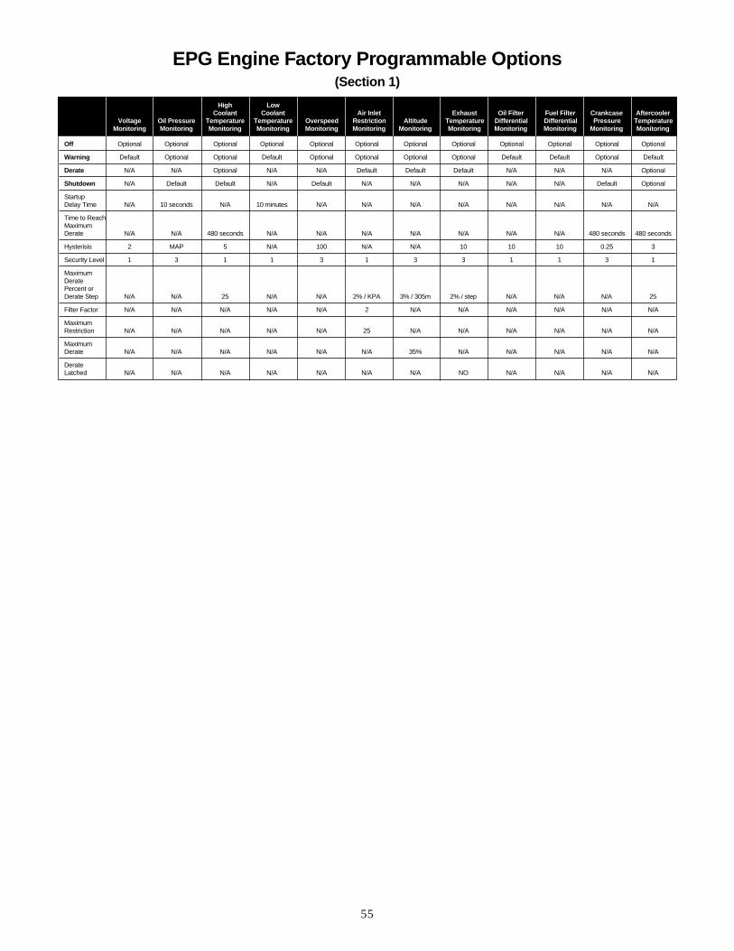
EPG Engine Factory Programmable Options(Section 1)
Off Optional Optional Optional Optional Optional Optional Optional Optional Optional Optional Optional Optional
Warning Default Optional Optional Default Optional Optional Optional Optional Default Default Optional Default
Derate N/A N/A Optional N/A N/A Default Default Default N/A N/A N/A Optional
Shutdown N/A Default Default N/A Default N/A N/A N/A N/A N/A Default Optional
StartupDelay Time N/A 10 seconds N/A 10 minutes N/A N/A N/A N/A N/A N/A N/A N/A
Time to ReachMaximumDerate N/A N/A 480 seconds N/A N/A N/A N/A N/A N/A N/A 480 seconds 480 seconds
Hysterisis 2 MAP 5 N/A 100 N/A N/A 10 10 10 0.25 3
Security Level 1 3 1 1 3 1 3 3 1 1 3 1
MaximumDerate Percent or Derate Step N/A N/A 25 N/A N/A 2% / KPA 3% / 305m 2% / step N/A N/A N/A 25
Filter Factor N/A N/A N/A N/A N/A 2 N/A N/A N/A N/A N/A N/A
Maximum Restriction N/A N/A N/A N/A N/A 25 N/A N/A N/A N/A N/A N/A
MaximumDerate N/A N/A N/A N/A N/A N/A 35% N/A N/A N/A N/A N/A
Derate Latched N/A N/A N/A N/A N/A N/A N/A NO N/A N/A N/A N/A
High Low Coolant Coolant Air Inlet Exhaust Oil Filter Fuel Filter Crankcase Aftercooler
Voltage Oil Pressure Temperature Temperature Overspeed Restriction Altitude Temperature Differential Differential Pressure TemperatureMonitoring Monitoring Monitoring Monitoring Monitoring Monitoring Monitoring Monitoring Monitoring Monitoring Monitoring Monitoring
56
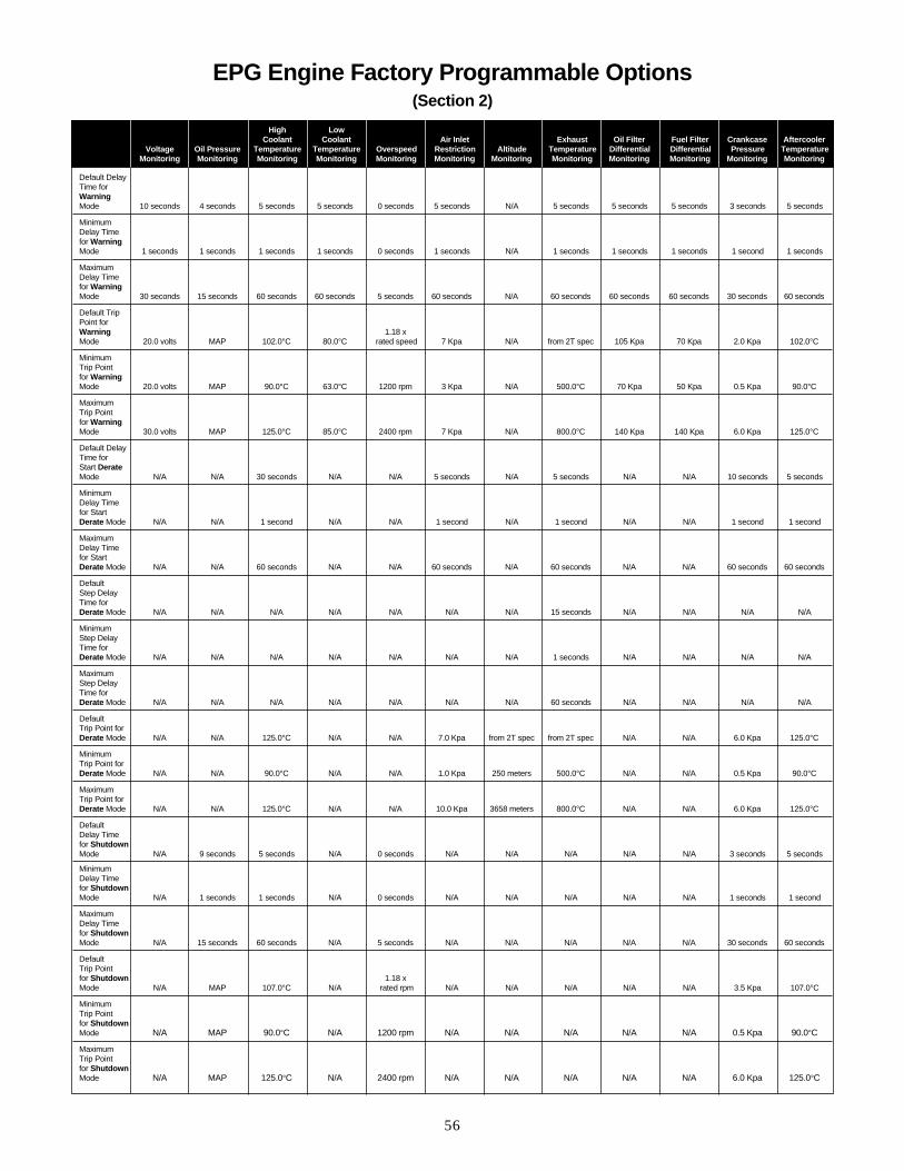
EPG Engine Factory Programmable Options(Section 2)
High Low Coolant Coolant Air Inlet Exhaust Oil Filter Fuel Filter Crankcase Aftercooler
Voltage Oil Pressure Temperature Temperature Overspeed Restriction Altitude Temperature Differential Differential Pressure TemperatureMonitoring Monitoring Monitoring Monitoring Monitoring Monitoring Monitoring Monitoring Monitoring Monitoring Monitoring Monitoring
Default Delay Time forWarningMode 10 seconds 4 seconds 5 seconds 5 seconds 0 seconds 5 seconds N/A 5 seconds 5 seconds 5 seconds 3 seconds 5 seconds
MinimumDelay Time for WarningMode 1 seconds 1 seconds 1 seconds 1 seconds 0 seconds 1 seconds N/A 1 seconds 1 seconds 1 seconds 1 second 1 seconds
MaximumDelay Time for WarningMode 30 seconds 15 seconds 60 seconds 60 seconds 5 seconds 60 seconds N/A 60 seconds 60 seconds 60 seconds 30 seconds 60 seconds
Default Trip Point for Warning 1.18 xMode 20.0 volts MAP 102.0°C 80.0°C rated speed 7 Kpa N/A from 2T spec 105 Kpa 70 Kpa 2.0 Kpa 102.0°C
Minimum Trip Point for WarningMode 20.0 volts MAP 90.0°C 63.0°C 1200 rpm 3 Kpa N/A 500.0°C 70 Kpa 50 Kpa 0.5 Kpa 90.0°C
Maximum Trip Point for WarningMode 30.0 volts MAP 125.0°C 85.0°C 2400 rpm 7 Kpa N/A 800.0°C 140 Kpa 140 Kpa 6.0 Kpa 125.0°C
Default Delay Time for Start DerateMode N/A N/A 30 seconds N/A N/A 5 seconds N/A 5 seconds N/A N/A 10 seconds 5 seconds
MinimumDelay Time for Start Derate Mode N/A N/A 1 second N/A N/A 1 second N/A 1 second N/A N/A 1 second 1 second
MaximumDelay Time for Start Derate Mode N/A N/A 60 seconds N/A N/A 60 seconds N/A 60 seconds N/A N/A 60 seconds 60 seconds
DefaultStep Delay Time for Derate Mode N/A N/A N/A N/A N/A N/A N/A 15 seconds N/A N/A N/A N/A
MinimumStep Delay Time for Derate Mode N/A N/A N/A N/A N/A N/A N/A 1 seconds N/A N/A N/A N/A
MaximumStep Delay Time for Derate Mode N/A N/A N/A N/A N/A N/A N/A 60 seconds N/A N/A N/A N/A
DefaultTrip Point for Derate Mode N/A N/A 125.0°C N/A N/A 7.0 Kpa from 2T spec from 2T spec N/A N/A 6.0 Kpa 125.0°C
MinimumTrip Point for Derate Mode N/A N/A 90.0°C N/A N/A 1.0 Kpa 250 meters 500.0°C N/A N/A 0.5 Kpa 90.0°C
MaximumTrip Point for Derate Mode N/A N/A 125.0°C N/A N/A 10.0 Kpa 3658 meters 800.0°C N/A N/A 6.0 Kpa 125.0°C
DefaultDelay Time for ShutdownMode N/A 9 seconds 5 seconds N/A 0 seconds N/A N/A N/A N/A N/A 3 seconds 5 seconds
MinimumDelay Time for ShutdownMode N/A 1 seconds 1 seconds N/A 0 seconds N/A N/A N/A N/A N/A 1 seconds 1 second
MaximumDelay Time for ShutdownMode N/A 15 seconds 60 seconds N/A 5 seconds N/A N/A N/A N/A N/A 30 seconds 60 seconds
DefaultTrip Point for Shutdown 1.18 xMode N/A MAP 107.0°C N/A rated rpm N/A N/A N/A N/A N/A 3.5 Kpa 107.0°C
MinimumTrip Point for ShutdownMode N/A MAP 90.0°C N/A 1200 rpm N/A N/A N/A N/A N/A 0.5 Kpa 90.0°C
MaximumTrip Point for ShutdownMode N/A MAP 125.0°C N/A 2400 rpm N/A N/A N/A N/A N/A 6.0 Kpa 125.0°C

57
Marine Engine Customer Programmable Options(Using Service Tools)
Off Optional Optional Optional Optional Optional Optional Optional Optional Optional Optional Optional Optional
Warning Default Default Default Default Default Optional Default Default Default Default Default Default
Derate N/A Optional N/A N/A Optional Default Optional N/A N/A N/A Optional N/A
Shutdown N/A Default N/A Optional N/A N/A N/A N/A N/A Optional Optional Optional
Default Delay Time forWarningMode 10 seconds 5 seconds 5 seconds 0 seconds 5 seconds N/A 5 seconds 5 seconds 5 seconds 3 seconds 5 seconds 4 seconds
Default TripPoint forWarning 1.15 x See ChartMode 20.0 volts 102.0°C 80.0°C rated speed 7 Kpa N/A from 2T spec 105 Kpa 70 Kpa 2.0 Kpa 102.0 Kpa Below
Default DelayTime for Start DerateMode N/A 30 seconds N/A N/A 5 seconds N/A 5 seconds N/A N/A N/A N/A N/A
Default StepDelay Time for DerateMode N/A N/A N/A N/A N/A N/A 15 seconds N/A N/A N/A N/A N/A
Default TripPoint forDerate Mode N/A 105.0°C N/A N/A 7 Kpa from 2T spec from 2T spec N/A N/A 6.0 Kpa 125°C N/A
Default DelayTime for ShutdownMode N/A 5 seconds N/A 0 seconds N/A N/A N/A N/A N/A 3 seconds 5 seconds 9 seconds
Default TripPoint forShutdown 1.15 xMode N/A 107.0°C N/A rated rpm N/A N/A N/A N/A N/A 3.5 Kpa 107.0°C MAP
High Low Coolant Coolant Air Inlet Exhaust Oil Filter Fuel Filter Crankcase Aftercooler
Voltage Temperature Temperature Overspeed Restriction Altitude Temperature Differential Differential Pressure Temperature Oil Pressure Monitoring Monitoring Monitoring Monitoring Monitoring Monitoring Monitoring Monitoring Monitoring Monitoring Monitoring Monitoring
58
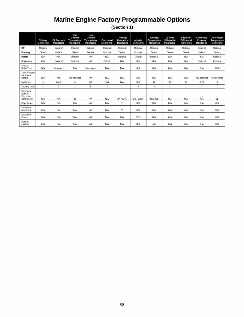
Marine Engine Factory Programmable Options(Section 1)
Off Optional Optional Optional Optional Optional Optional Optional Optional Optional Optional Optional Optional
Warning Default Default Default Default Optional Default Optional Default Default Default Default Default
Derate N/A N/A Optional N/A N/A Optional Default Optional N/A N/A N/A Optional
Shutdown N/A Optional Optional N/A Default N/A N/A N/A N/A N/A Optional Optional
StartupDelay Time N/A 10 seconds N/A 10 minutes N/A N/A N/A N/A N/A N/A N/A N/A
Time to ReachMaximumDerate N/A N/A 480 seconds N/A N/A N/A N/A N/A N/A N/A 480 seconds 480 seconds
Hysterisis 2 MAP 5 N/A 100 N/A N/A 10 10 10 0.25 3
Security Level 1 3 1 1 3 1 3 3 1 1 3 1
MaximumDerate Percent or Derate Step N/A N/A 25 N/A N/A 2% / KPA 3% / 305m 2% / step N/A N/A N/A 25
Filter Factor N/A N/A N/A N/A N/A 2 N/A N/A N/A N/A N/A N/A
Maximum Restriction N/A N/A N/A N/A N/A 25 N/A N/A N/A N/A N/A N/A
MaximumDerate N/A N/A N/A N/A N/A N/A 35% N/A N/A N/A N/A N/A
Derate Latched N/A N/A N/A N/A N/A N/A N/A NO N/A N/A N/A N/A
High Low Coolant Coolant Air Inlet Exhaust Oil Filter Fuel Filter Crankcase Aftercooler
Voltage Oil Pressure Temperature Temperature Overspeed Restriction Altitude Temperature Differential Differential Pressure TemperatureMonitoring Monitoring Monitoring Monitoring Monitoring Monitoring Monitoring Monitoring Monitoring Monitoring Monitoring Monitoring
59
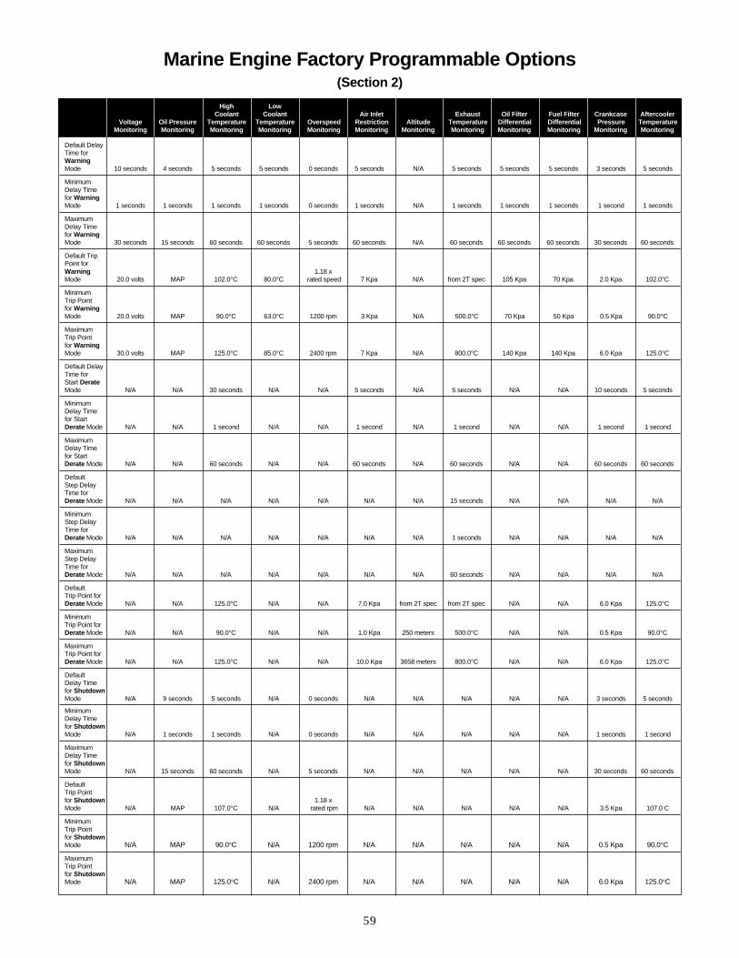
Marine Engine Factory Programmable Options(Section 2)
High Low Coolant Coolant Air Inlet Exhaust Oil Filter Fuel Filter Crankcase Aftercooler
Voltage Oil Pressure Temperature Temperature Overspeed Restriction Altitude Temperature Differential Differential Pressure TemperatureMonitoring Monitoring Monitoring Monitoring Monitoring Monitoring Monitoring Monitoring Monitoring Monitoring Monitoring Monitoring
Default Delay Time forWarningMode 10 seconds 4 seconds 5 seconds 5 seconds 0 seconds 5 seconds N/A 5 seconds 5 seconds 5 seconds 3 seconds 5 seconds
MinimumDelay Time for WarningMode 1 seconds 1 seconds 1 seconds 1 seconds 0 seconds 1 seconds N/A 1 seconds 1 seconds 1 seconds 1 second 1 seconds
MaximumDelay Time for WarningMode 30 seconds 15 seconds 60 seconds 60 seconds 5 seconds 60 seconds N/A 60 seconds 60 seconds 60 seconds 30 seconds 60 seconds
Default Trip Point for Warning 1.18 xMode 20.0 volts MAP 102.0°C 80.0°C rated speed 7 Kpa N/A from 2T spec 105 Kpa 70 Kpa 2.0 Kpa 102.0°C
Minimum Trip Point for WarningMode 20.0 volts MAP 90.0°C 63.0°C 1200 rpm 3 Kpa N/A 500.0°C 70 Kpa 50 Kpa 0.5 Kpa 90.0°C
Maximum Trip Point for WarningMode 30.0 volts MAP 125.0°C 85.0°C 2400 rpm 7 Kpa N/A 800.0°C 140 Kpa 140 Kpa 6.0 Kpa 125.0°C
Default Delay Time for Start DerateMode N/A N/A 30 seconds N/A N/A 5 seconds N/A 5 seconds N/A N/A 10 seconds 5 seconds
MinimumDelay Time for Start Derate Mode N/A N/A 1 second N/A N/A 1 second N/A 1 second N/A N/A 1 second 1 second
MaximumDelay Time for Start Derate Mode N/A N/A 60 seconds N/A N/A 60 seconds N/A 60 seconds N/A N/A 60 seconds 60 seconds
DefaultStep Delay Time for Derate Mode N/A N/A N/A N/A N/A N/A N/A 15 seconds N/A N/A N/A N/A
MinimumStep Delay Time for Derate Mode N/A N/A N/A N/A N/A N/A N/A 1 seconds N/A N/A N/A N/A
MaximumStep Delay Time for Derate Mode N/A N/A N/A N/A N/A N/A N/A 60 seconds N/A N/A N/A N/A
DefaultTrip Point for Derate Mode N/A N/A 125.0°C N/A N/A 7.0 Kpa from 2T spec from 2T spec N/A N/A 6.0 Kpa 125.0°C
MinimumTrip Point for Derate Mode N/A N/A 90.0°C N/A N/A 1.0 Kpa 250 meters 500.0°C N/A N/A 0.5 Kpa 90.0°C
MaximumTrip Point for Derate Mode N/A N/A 125.0°C N/A N/A 10.0 Kpa 3658 meters 800.0°C N/A N/A 6.0 Kpa 125.0°C
DefaultDelay Time for ShutdownMode N/A 9 seconds 5 seconds N/A 0 seconds N/A N/A N/A N/A N/A 3 seconds 5 seconds
MinimumDelay Time for ShutdownMode N/A 1 seconds 1 seconds N/A 0 seconds N/A N/A N/A N/A N/A 1 seconds 1 second
MaximumDelay Time for ShutdownMode N/A 15 seconds 60 seconds N/A 5 seconds N/A N/A N/A N/A N/A 30 seconds 60 seconds
DefaultTrip Point for Shutdown 1.18 xMode N/A MAP 107.0°C N/A rated rpm N/A N/A N/A N/A N/A 3.5 Kpa 107.0 C
MinimumTrip Point for ShutdownMode N/A MAP 90.0°C N/A 1200 rpm N/A N/A N/A N/A N/A 0.5 Kpa 90.0°C
MaximumTrip Point for ShutdownMode N/A MAP 125.0°C N/A 2400 rpm N/A N/A N/A N/A N/A 6.0 Kpa 125.0°C

60
Monitoring System Features and Capabilities
Pilot House Panels for 3500B Marine Engines will include various configurations of the following components:
Control Groups Display fault lights and digital reading of gauges, engine speed, and analog Display of various performance and operation parameters
Toggle switch Control digital display of analog gauge readings
Engine Control Module Green is on while both ECMs are operational, amber comes on if primary monitoring lamps ECM fails
Emergency stop switch Protected against accidental actuation by a protective ring
Dimmer switch Control the amber nightvision lamps inside the control group
Start-stop switch Starts and stops the engine remotely
These panels may be installed a maximum of 100 ft from the engine.
Pilot House Instrument Panels
Part Number
123-8212 Premium Panel
123-8210Basic Panel
123-8211Basic Panelwith Switches
Picture of Panel

61
122-0132 Pilot House Panel(Guages and LED Parameters)
1 - System Shutdown2 - Hi JW Temp3 - Oil Pres4 - Hi Exh Manifold Temp5 - Engine Coolant Level6 - Fuel Pres7 - Mar Gear Oil Temp8 - Mar Gear Oil Pres9 - System Voltage
10 - Diagnostic Indicator
A - Oil PresB - Coolant TempC - Mar Gear Oil Pres D - Mar Gear Oil Temp
E - LH Exh Manifold TempF - RH Exh Manifold TempG - Boost PresH - Aftercooler Temp
Cutouts for various components of Pilot House Panels

62
Marine Engine Monitoring System DefaultsService Tool Customer Programmable Options
Off Optional Optional Optional Optional Optional Optional Optional Optional Optional Optional Optional Optional
Warning Optional Optional Optional Optional Optional Optional Optional Optional Optional Optional Optional Optional
Derate N/A N/A Optional N/A N/A Optional Optional Optional N/A N/A Optional Optional
Shutdown N/A N/A N/A N/A Optional N/A N/A N/A N/A N/A N/A N/A
Default Delay Time forWarningMode 10 seconds 4 seconds 5 seconds 5 seconds 0 seconds 5 seconds N/A 5 seconds 5 seconds 5 seconds 3 seconds 5 seconds
Default TripPoint forWarning 1.18 xMode 20.0 volts MAP 102.0°C 80.0°C rated speed 7 Kpa N/A from 2T spec 105 Kpa 105 Kpa 2.0 Kpa 102.0°C
Default DelayTime for Start DerateMode N/A N/A 30 seconds N/A N/A 5 seconds N/A 5 seconds N/A N/A N/A N/A
Default StepDelay Time for DerateMode N/A N/A N/A N/A N/A N/A N/A 15 seconds N/A N/A N/A N/A
Default TripPoint forDerate Mode N/A N/A 107.0°C N/A N/A 7 Kpa from 2T spec from 2T spec N/A N/A 6.0 Kpa 107.0°C
Default DelayTime for ShutdownMode N/A 9 seconds 5 seconds N/A 0 seconds N/A N/A N/A N/A N/A 3 seconds 5 seconds
Default TripPoint forShutdown 1.18 x Mode N/A MAP 107.0°C N/A rated rpm N/A N/A N/A N/A N/A 3.5 Kpa 107.0°C
High Low Coolant Coolant Air Inlet Exhaust Oil Filter Fuel Filter Crankcase Aftercooler
Voltage Oil Pressure Temperature Temperature Overspeed Restriction Altitude Temperature Differential Differential Pressure TemperatureMonitoring Monitoring Monitoring Monitoring Monitoring Monitoring Monitoring Monitoring Monitoring Monitoring Monitoring Monitoring

63
Marine Engine Monitoring System DefaultsApplication Builder Factory Programmable System Defaults
Off Enabled Enabled Enabled Enabled Enabled Enabled Enabled Enabled Enabled Enabled Enabled Enabled
Warning Enabled Enabled Enabled Enabled Enabled Enabled Enabled Enabled Enabled Enabled Enabled Enabled
Derate N/A N/A Enabled N/A N/A Enabled Enabled Enabled N/A N/A Enabled Enabled
Shutdown N/A N/A N/A N/A Enabled N/A N/A N/A N/A N/A N/A N/A
Startup Delay Time to Reach MaximumDerate N/A 10 seconds N/A 10 minutes N/A N/A N/A N/A N/A N/A N/A N/A
ReachMaximumDerate N/A N/A 480 seconds N/A N/A N/A N/A N/A N/A N/A 480 seconds 480 seconds
Hysterisis 2 MAP 5 N/A 100 N/A N/A 10 10 10 0.25 3
Security Level 1 3 3 3 3 3 3 3 1 1 3 3
MaximumDerate Percent or Derate Step N/A N/A 25 N/A N/A 2% / KPA 3% / 305m 2% / step N/A N/A N/A 25
Filter Factor N/A N/A N/A N/A N/A 2 N/A N/A N/A N/A N/A N/A
Maximum Restriction N/A N/A N/A N/A N/A 25 N/A N/A N/A N/A N/A N/A
MaximumDerate N/A N/A N/A N/A N/A N/A 35% N/A N/A N/A N/A N/A
Derate Latched N/A N/A N/A N/A N/A N/A N/A NO N/A N/A N/A N/A
High Low Coolant Coolant Air Inlet Exhaust Oil Filter Fuel Filter Crankcase Aftercooler
Voltage Oil Pressure Temperature Temperature Overspeed Restriction Altitude Temperature Differential Differential Pressure TemperatureMonitoring Monitoring Monitoring Monitoring Monitoring Monitoring Monitoring Monitoring Monitoring Monitoring Monitoring Monitoring

64
Marine Engine Monitoring System DefaultsApplication Builder Factory Programmable Parameters
High Low Coolant Coolant Air Inlet Exhaust Oil Filter Fuel Filter Crankcase Aftercooler
Voltage Oil Pressure Temperature Temperature Overspeed Restriction Altitude Temperature Differential Differential Pressure TemperatureMonitoring Monitoring Monitoring Monitoring Monitoring Monitoring Monitoring Monitoring Monitoring Monitoring Monitoring Monitoring
Default Delay Time forWarningMode 10 seconds 4 seconds 5 seconds 5 seconds 0 seconds 5 seconds N/A 5 seconds 5 seconds 5 seconds 3 seconds 5 seconds
MinimumDelay Time for WarningMode 1 seconds 1 seconds 1 seconds 1 seconds 0 seconds 1 seconds N/A 1 seconds 1 seconds 1 seconds 1 second 1 seconds
MaximumDelay Time for WarningMode 30 seconds 15 seconds 60 seconds 60 seconds 5 seconds 60 seconds N/A 60 seconds 60 seconds 60 seconds 30 seconds 60 seconds
Default Trip Point for Warning 1.18 xMode 20.0 volts MAP 102.0°C 80.0°C rated speed 7 Kpa N/A from 2T spec 105 Kpa 70 Kpa 2.0 Kpa 50.0°C
Minimum Trip Point for WarningMode 20.0 volts MAP 90.0°C 63.0°C 1200 rpm 3 Kpa N/A 500.0°C 70 Kpa 50 Kpa 0.5 Kpa 40.0°C
Maximum Trip Point for WarningMode 30.0 volts MAP 125.0°C 85.0°C 2400 rpm 7 Kpa N/A 800.0°C 140 Kpa 140 Kpa 6.0 Kpa 125.0°C
Default Delay Time for Start DerateMode N/A N/A 30 seconds N/A N/A 5 seconds N/A 5 seconds N/A N/A 10 seconds 5 seconds
MinimumDelay Time for Start Derate Mode N/A N/A 1 second N/A N/A 1 second N/A 1 second N/A N/A 1 second 1 second
MaximumDelay Time for Start Derate Mode N/A N/A 60 seconds N/A N/A 60 seconds N/A 60 seconds N/A N/A 60 seconds 60 seconds
DefaultStep Delay Time for Derate Mode N/A N/A N/A N/A N/A N/A N/A 15 seconds N/A N/A N/A N/A
MinimumStep Delay Time for Derate Mode N/A N/A N/A N/A N/A N/A N/A 1 seconds N/A N/A N/A N/A
MaximumStep Delay Time for Derate Mode N/A N/A N/A N/A N/A N/A N/A 60 seconds N/A N/A N/A N/A
DefaultTrip Point for Derate Mode N/A N/A 125.0°C N/A N/A 7.0 Kpa from 2T spec from 2T spec N/A N/A 6.0 Kpa 125.0°C
MinimumTrip Point for Derate Mode N/A N/A 90.0°C N/A N/A 1.0 Kpa 250 meters 500.0°C N/A N/A 0.5 Kpa 50.0°C
MaximumTrip Point for Derate Mode N/A N/A 125.0°C N/A N/A 10.0 Kpa 3658 meters 800.0°C N/A N/A 6.0 Kpa 125.0°C
DefaultDelay Time for ShutdownMode N/A 9 seconds 5 seconds N/A 0 seconds N/A N/A N/A N/A N/A 3 seconds 5 seconds
MinimumDelay Time for ShutdownMode N/A 1 seconds 1 seconds N/A 0 seconds N/A N/A N/A N/A N/A 1 seconds 1 second
MaximumDelay Time for ShutdownMode N/A 15 seconds 60 seconds N/A 5 seconds N/A N/A N/A N/A N/A 30 seconds 60 seconds
DefaultTrip Point for Shutdown 1.18 xMode N/A MAP 107.0°C N/A rated rpm N/A N/A N/A N/A N/A 3.5 Kpa 107.0°C
MinimumTrip Point for ShutdownMode N/A MAP 90.0°C N/A 1200 rpm N/A N/A N/A N/A N/A 0.5 Kpa 50.0°C
MaximumTrip Point for ShutdownMode N/A MAP 125.0°C N/A 2400 rpm N/A N/A N/A N/A N/A 6.0 Kpa 125.0°C

65
InstrumentsThere are are a minimum of two standardconfigurations of the 3500B instrument panels.The standby EPG package with switchgearconversion will have two modules as standard,while the other EPG packages with switchgearconversion and all other engine applications willhave three modules as standard with the option toadd a fourth module and a pyrometer. The twomodules included with every instrument box arethe main display module and gauge clustermodule. The main display module controls all theinstruments and gauge cluster module displays:
• Engine oil pressure• Engine coolant temperature• System voltage• Engine fuel pressure
Applications other than standby EPG have asecond gauge cluster module which displays:
• Right hand and left hand air inlet restriction• Right hand and left hand exhaust temperature• Fuel filter differential pressure• Oil filter differential pressure
There is an option to add a third gauge clustermodule. The third gauge cluster module for EPGapplications displays:
• Inlet air pressure (boost)• Separate circuit aftercooler coolant temperature• Engine oil temperature• Inlet air temperature
The third gauge cluster module for marineapplications displays:
• Inlet air pressure (boost)• Separate circuit aftercooler coolant temperature• Marine gear oil temperature• Marine gear oil pressure
3500B Electronic Instrument Panel
66
Engine Control SwitchThe engine control switch has four positions and isused to control the engine.
1. The OFF/RESET position removes power fromthe engine.
2. The AUTO position powers up the enginecontrol module (ECM) and allows the ECM tomonitor the status of a remote start / stopswitch. Note: The customer remote start/stopswitch, if equipped, is a switch that can bewired into the system through the customerconnector “C” to provide a method to remotelystart and stop the engine. When the enginecontrol switch is in the AUTO position, aremote switch can be used to place the engine inthree different states. The remote OFF positionleaves the ECM powered up. The ECM is in apower conserving mode where there is reducedpower usage. The remote COOLDOWN/STOPposition places the engine in a cooldown mode(if programmed to cooldown) and then stops theengine. The remote START/RUN positionstarts the engine cycle crank sequence andallow the engine to continue to run once it is started.
3. The MANUAL/START position starts theengine cycle crank sequence and allow theengine to continue to run once it is started.
4. The STOP position places the engine in acooldown mode (if programmed to cooldown)and then shuts off the engine.
Emergency Stop Push ButtonThe emergency stop push button is used to bringthe engine to a quick stop during emergencysituations. The emergency stop push buttonremoves power from the ECM and activates theair shutoffs (if installed).
Note: The customer remote shutdown switch, ifequipped, is a switch that can be wired into thesystem through customer connection “C”. Thisswitch will disable fuel injection and activate theair shutoffs (if equipped).
Main Display Module Control SwitchesThe electronic instrument panel houses threeswitches that are used to interface with the maindisplay module.
1. The CLEAR/MODE switch is used to movebetween the five available modes of operationand to clear information that is currently beingdisplayed on the main display module. Themain display module will cycle through the fivedifferent modes of operation when theCLEAR/MODE switch is held down in themode position. When the desired mode isreached, release the switch and the maindisplay module will remain in that mode ofoperation until a different switch input isreceived. If the information that is currentlybeing displayed by the main display module isno longer needed and the information is to beremoved from memory, the displayedinformation can be cleared by holding theCLEAR/MODE switch up in the clear positionfor approximately one second until theinformation disappears from the main display module.
2. The SCROLL switch is used to scroll throughthe different parameter information that isavailable in a single mode. The main displaymodule will scroll through the parameterdisplay information that is available in theactive mode when the SCROLL switch is heldin the up position. If a continuous display of aparameter is desired, hold the SCROLL switchin the scroll position until the desiredparameter information is displayed. Release the SCROLL switch when the desiredparameter information is displayed. Theparameter information will be displayed untilthe main display module receives a differentinput.
3. The LH/RH switch is used to display both theright and left hand parameter information on asingle gauge. Instrument boxes that have asecond gauge cluster module (two gauges thatdisplay air inlet restriction pressure andexhaust temperature) can show both right handand left hand values for the engine. Whiledisplaying parameter information for one or theother of these parameters, the right hand andleft hand switch can be toggled back and forthso that all of the information can be displayed.

67
AlarmThe alarm is activated by the main displaymodule. The alarm is turned on anytime there is asystem alarm, a parameter out of range, or thereis an active diagnostic condition.
Alarm Silence SwitchThe alarm silence switch is a push button switchthat allows the operator to turn off the alarm oncethe alarm has sounded. Activating the alarmsilence switch will silence the alarm for fiveminutes. After the the five minute period, if theconditions that initiated the alarm have not beencorrected, the alarm will sound again.
Circuit Breakers and WiringInside the electronic instrument panel arenumerous circuit breakers to protect the electricalsystem and wiring for the control system. Thefollowing circuits are protected by circuit breakers.
• Starter/Emergency Stop Circuit• Battery Power Circuit• Relay Circuit• Starter Relay Circuit• ECM Circuit• SEMS Circuit• Alternator Circuit (an attachment)
Marine applications have these additional circuitbreakers.
• Customer Power Circuit• Control Switch Circuit• Secondary ECM Circuit
Customer Interface ConnectorsThere are two customer interface connectorslocated on the bottom of the electronic instrumentpanel. The customer connector “D” (24 PinConnector) provides access to the battery ground,switched battery positive, and unswitched batterpositive. For marine applications, this connectoralso provides (+) battery and (-) battery access forthe throttle sensor (if equipped), secondary ECMready lamp, and secondary ECM active lamp.

68
The customer connector “C” (40 pin connector)provides access to all customer attachments andsystem enhancements. Attachments that interfacethrough this connector for EPG applicationsinclude: speed adjust potentiometer (when notusing the Woodward Load Share Module), fuellevel switch, charger fault, coolant level switch,customer remote start/stop switch, customer
remote emergency stop switch, inlet airtemperature, and engine oil temperature.Attachments that interface through this connectorfor marine application include: marine gear oiltemperature, marine gear oil pressure, fuel levelswitch, coolant level switch, customer remotestart/stop switch, and customer remote emergencystop switch.
EPG Applications - Customer Connector “D” Pin Number Function Type
1-16 Uncommitted Uncommitted
17 Ground Battery (-)
18 Ground Battery (-)
19 Ground Battery (-)
20 Ground Battery (-)
21-24 Uncommitted Uncommitted
Marine Applications - Customer Connector “D”Pin Number Function Type
1 Throttle Synchronization Switch Battery (+) Switched
2 Throttle Synchronization Switch Battery (+) Switched
3 Port Throttle Position Sensor Battery (+) Switched
4 Starboard Throttle Position Sensor Battery (+) Switched
5 Secondary ECM Ready Lamp Battery (+) Switched
6 Secondary ECM Active Lamp Battery (+) Switched
7 Uncommitted Battery (+) Unswitched
8 Uncommitted Battery (+) Unswitched
9 Uncommitted Battery (+) Unswitched
10 Uncommitted Battery (+) Unswitched
11 Uncommitted Battery (+) Unswitched
12 Uncommitted Battery (+) Unswitched
13 Throttle Synchronization Switch Battery (-)
14 Throttle Synchronization Switch Battery (-)
15 Port Throttle Position Sensor Battery (-)
16 Starboard Throttle Position Sensor Battery (-)
17 Fuel Level Switch Battery (-)
18 Transmission Oil Pressure Sensor Battery (-)
19 Transmission Oil Temperature Sensor Battery (-)
20 Coolant Level Sensor Battery (-)
21 Uncommitted Battery (-)
22 Uncommitted Battery (-)
23 Uncommitted Battery (-)
24 Uncommitted Battery (-)

69
EPG Applications - Customer Connector “C”1-13 Uncommitted
14 Gen Set On Line
15 Uncommitted
16 Battery Charger Fault
17 Uncommitted
18 Fuel Level Switch
19 Digital Return (From Woodward Load Share Module Pin 20)
20 Digital Return (Remote Customer Shutdown Switch)
21 Digital Return (Remote Start / Stop Switch)
22 Uncommitted
23 Uncommitted
24 Uncommitted
25 Coolant Level Sensor
26 Uncommitted
27 Air Inlet Temperature Sensor
28 Coolant Level Sensor (Signal)
29 Remote Start / Stop Switch
30 Remote Start / Stop Switch
31 Remote Start / Stop Switch
32 Remote Start / Stop Switch
33 Remote Start / Stop Switch
34 Remote Start / Stop Switch
35 Engine Oil Temperature Sensor
36 Pulse Width Modulated Signal (from Woodward Load Share Module Pin 19)
37 Speed Adjust Potentiometer (Speed Control Brick)
38 Speed Adjust Potentiometer (Speed Control Brick)
39 Speed Adjust Potentiometer (Speed Control Brick)
40 Uncommitted

70
Marine Applications - Customer Connector “C” 1 Throttle Synchronization Switch
2 Throttle Synchronization Switch
3 Port Throttle Position Sensor (Signal)
4 Starboard Throttle Position Sensor (Signal)
5 Secondary Engine Control Module Ready Lamp
6 Secondary Engine Control Module Active Lamp
7 Connect to Starboard Engine Customer Connector Pin 7
8 Connect to Starboard Engine Customer Connector Pin 8
9 Connect to Starboard Engine Customer Connector Pin 9
10 Connect to Starboard Engine Customer Connector Pin 10
11 Cat Data Link (-)
12 Cat Data Link (+)
13 Shutdown Notify Relay (common)
14 Uncommitted
15 Shutdown Notify relay (Normally Closed)
16 Uncommitted
17 Shutdown Notify relay (Normally Closed)
18 Fuel Level Switch
19 Digital Return (Remote Customer Shutdown Switch)
20 Digital Return (Remote Start / Stop Switch)
21 Digital Return
22 Uncommitted
23 Transmission Oil Pressure Sensor (Voltage Supply)
24 Transmission Oil Temperature Sensor (Voltage Supply)
25 Coolant Level Sensor (Signal)
26 Transmission Oil Pressure Sensor (Signal)
27 Transmission Oil Temperature Sensor (Signal)
28 Coolant Level Sensor (Signal)
29 Remote Start / Stop Switch
30 Remote Start / Stop Switch
31 Remote Start / Stop Switch
32 Remote Start / Stop Switch
33 Remote Customer Shutdown Switch
34 Remote Customer Shutdown Switch
35 Engine Oil Temperature Sensor
36 Uncommitted
37 Uncommitted
38 Uncommitted
39 Uncommitted
40 Uncommitted

71
Internal Instrument Panel SwitchesInside the electronic instrument panel are threeswitches that are located in the upper left corner.For EPG applications, the switches are used for:
• Manual starter crank switch• Overspeed verify switch• Hi / low idle switch
For marine application, the switches are used for:
• Manual starter crank switch• Overspeed verify switch• Prelube override switch
Note: Prelube override switch is present only ifthe prelube pump attachment is part of the enginepackage.
The MANUAL STARTER CRANK SWITCHallows the operator to crank the engine using theengine starters and overriding any other controlor protection systems. Therefore, the starters canbe engaged even when the engine control switch isin the “OFF” position or when the ECM hascompleted the cycle crank sequence. The manualstarter crank switch is intended to be used forsystem troubleshooting and engine maintenance.The manual starter crank switch should not beused for normal operation of the engine.
The OVERSPEED VERIFY SWITCH allows theoperator to verify that the overspeed protectionsystem is working as desired. When the switch isactivated, the ECM will perform an engineoverspeed shutdown (if the Engine MonitoringSystem is programmed for this action) at 75% ofthe engine overspeed trip point. The overspeedverify switch is intended to be used fortroubleshooting and verification of engineprotection systems.
The HIGH/LOW SWITCH allows the operator ofan EPG engine to hold the engine speed at theprogrammed low idle setting. When the high/lowswitch is activated, the engine will remain at thelow idle setting. If the high/low switch is de-activated, the engine will proceed to the high idlesetting. The high/low switch is intended to be usedfor troubleshooting and any time that it is desiredto keep the engine at low idle.
The PRELUBE OVERRIDE SWITCH allows theoperator of a marine engine to override theprelube pump sequence at the beginning of thecycle crank sequence during engine start-up (ifthere is an attached prelube pump as part of theengine system). When the prelube override switchis activated, the ECM will not initiate an engineprelube prior to cranking the engine (the ECMwill immediately begin to crank the enginewithout prelubing). The prelube override switch isintended to be used for troubleshooting and toprovide for immediate engine starting duringemergency situations.
For additional information on the ElectronicInstrument Panel, see “Service Manual - 3500B Electronic Instrument Panel”, Form Number SENR6587 dated July 1995.

72
3500 Caterpillar Electronic TechnicianIntroductionCaterpillar Electronic Technician (ET) is a software program that will help find problems quickly andanalyze how to correct them. ET provides you with the capability to access and program the ElectronicControl Module (ECM) from a personal computer. The functionality is similar to the CaterpillarElectronic Control Analyzer Program (ECAP) tool.
How it worksWith ET you can display the status of a group ofparameters (temperatures, pressures, etc.)simultaneously, view and clear active and loggeddiagnostics, or display the current configuration ofan ECM. These and many other tasks critical toyour job can be performed with ET.
A graphical interface make this Microsoft®
Windows™ based software quick to learn and easyto use. The version and identification of your ECMis automatically retrieved by ET, and displayed onsummary screen when you start the program.Diagnostic tests and calibrations can also beperformed with the software. You’ll find ET mucheasier to use than the ECAP tool.
Features• Display parameter status• View active diagnostics
• View and clear logged diagnostics• View events where irregularities occurred and
where logged by the ECM• Perform diagnostic tests• Perform calibrations• Retrieve engine totals for fuel used, miles
traveled, etc. • Included is Caterpillar Flash Memory Software
used for uploading new Personality Module datato the ECM
• Works with Caterpillar Common ServicesModules
• An on-line help system is available. For additional help, contact the PC Hotline:
USA and Canada _ 1-800-843-7237Other Countries _ 309-674-5290Fax: 1-309 672-1403E-Mail: _ THEPCDR ADCCHOST

73
PC RequirementsMinimum Requirements
IBM PC compatible with 386 25 MHz SL or SXLprocessor
• 4 Mb of RAM• 10 Mb of available hard disk space• 3.5 in. 1.44 Mb diskette Drive• VGA monitor or display• PC or MS DOS® 5.0 or greater• Microsoft Windows version 3.1• RS232 port not used by mouse or printerRecommended Portable Unit
• IBM PC compatible with 486 33 MHz SL or greater
• 16 Mb of RAM• 200 Mb of available hard disk space• 3.5 in. 1.44 Mb diskette Drive• Super VGA monitor or display• OS/2 version 2.1• PC or MS DOS® 6.2 or greater• Microsoft Windows version 3.1• RS232 port with high speed UART chip• Pointing device or mouse
Other Requirements• 7X1700 Communications Adapter• NEXG4523 program module (Software for
7X1700 communications adapter version 1.2• 7X1688 RS232 cable
Wiring (required to install the engines)
• Acceptable Wire Types - Three conductor, 16 gauge, shielded cable (grounded at the endfurthest from the engine) are required forthrottle signal connections.
• “Twisted Pair” (not less than 1 turn per inch), 16 gauge wire must be used for all “DataLink”connections. All other customer connectionsmay be made with 16 gauge.
• Connection Practices - Deutsch connectors arethe approved method of making connections (See tool list)
• Connections paralleling the Family of BGenerator sets with Cummins Generators setsare practical. Special modifications are requiredto connect to Barber Coleman ILS module.
3500B EPG Diesel Electronic Service ToolsThe Caterpillar Service Tools for the 3500B EPGDiesel System are designed to help the servicetechnician analyze and locate problems within thesystem. Their use is required in order to performsensor calibrations and to read or changeprogrammable engine parameters.
Two Service tools can be used with the 3500BEPG Diesel engine. The Electronic Technician(ET) or the Electronic Control Analyzer andProgrammer (ECAP). With either ET or ECAP, aCommunication Adapter tool is required tocommunicate with the 3500B Electronic ControlModule (ECM). ET is the preferred tool due to itsincreased functionality, however, the ECAP can beused to perform basic troubleshooting.

74
Electronic Technician (ET)ET consists of an IBM compatible computer(laptop) and software programs. The softwareprograms allow the laptop to program ECMparameters, read and display sensor values and switches, perform diagnostic test andcalibrate sensors.
The following table outlines the tools and cablesneeded to use ET to service the 3500B EPG Dieselengine:
Part Number Description
None 1 IBM PC Compatible - Minimum of 386 (25 mHz)
JERD 2124 1 Single User License for ET version 1.4 (Main ET Program) (Min)
JERD2129 1 Data subscription for all engines and machines.
(Allows ET to communicate with 3500B engines.)
7X1700 3 Communication Adapter Group for use between ET Tool and ECM.
Includes 7X1701 Communication Adapter Tool, 6V3072 Case, 7X1424 Block,
7X1571 Fuse, 7X1569 Fuse, NEEG2464m and SEHS9264
NEXG4523 2 SPM for 7X1700 Communication Adapter Group.
7X1688 Connector Cable (CA to PC) Connects PC (laptop) to Communication Adapter.
7X1570 Connector Cable (CA to ECM) Connects 3500B EPG Diesel ECM to Communication
Adapter tool.
7X1412 Connector Cable - (CA to ECM) ATA Cable connection.
1 Contact the PC hotline at 1-800-THE-PCDR (843-7237) for more information.2 This is a subscription, since it is anticipated that it will be changing at regular intervals.3 Refer to Tool Operating Manual SEHS9264, Installation and Use of the 7X1701 Communication Adapter Tool.
3500B EPG Diesel Electronic Service Tools
The following Components are required to use Caterpillar Electronic Technician (ET)
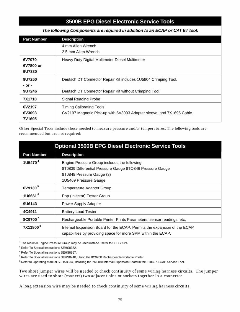
75
Part Number Description
4 mm Allen Wrench
2.5 mm Allen Wrench
6V7070 Heavy Duty Digital Multimeter Diesel Multimeter
6V7800 or
9U7330
9U7250 Deutsch DT Connector Repair Kit includes 1U5804 Crimping Tool.
- or -
9U7246 Deutsch DT Connector Repair Kit without Crimping Tool.
7X1710 Signal Reading Probe
6V2197 Timing Calibrating Tools
6V3093 CV2197 Magnetic Pick-up with 6V3093 Adapter sleeve, and 7X1695 Cable.
7V1695
3500B EPG Diesel Electronic Service Tools
The following Components are required in addition to an ECAP or CAT ET tool:
Part Number Description
1U5470 4 Engine Pressure Group includes the following:
8T0839 Differential Pressure Gauge 8TO846 Pressure Gauge
8T0848 Pressure Gauge (3)
1U5469 Pressure Gauge
6V9130 5 Temperature Adapter Group
1U6661 6 Pop (Injector) Tester Group
9U6143 Power Supply Adapter
4C4911 Battery Load Tester
8C9700 7 Rechargeable Portable Printer Prints Parameters, sensor readings, etc,
7X11800 8 Internal Expansion Board for the ECAP. Permits the expansion of the ECAP
capabilities by providing space for more SPM within the ECAP.
Optional 3500B EPG Diesel Electronic Service Tools
Other Special Tools include those needed to measure pressure and/or temperatures. The following tools arerecommended but are not required:
4 The 6V9450 Engine Pressure Group may be used instead. Refer to SEHS8524.5 Refer To Special Instructions SEHS8382.6 Refer To Special Instructions SEHS8867.7 Refer To Special Instructions SEHS8740, Using the 8C9700 Rechargeable Portable Printer.8 Refer to Operating Manual SEHS8834, Installing the 7X1180 Internal Expansion Board in the 8T8697 ECAP Service Tool.
Two short jumper wires will be needed to check continuity of some wiring harness circuits. The jumperwires are used to short (connect) two adjacent pins or sockets together in a connector.
A long extension wire may be needed to check continuity of some wiring harness circuits.
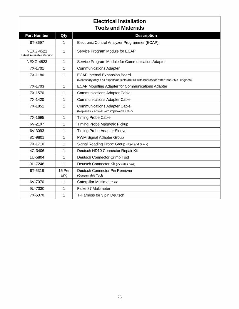
76
Electrical Installation Tools and Materials
Part Number Qty Description
8T-8697 1 Electronic Control Analyzer Programmer (ECAP)
NEXG-4521 1 Service Program Module for ECAPLatest Available Version
NEXG-4523 1 Service Program Module for Communication Adapter
7X-1701 1 Communications Adapter
7X-1180 1 ECAP Internal Expansion Board (Necessary only if all expansion slots are full with boards for other-than-3500 engines)
7X-1703 1 ECAP Mounting Adapter for Communications Adapter
7X-1570 1 Communications Adapter Cable
7X-1420 1 Communications Adapter Cable
7X-1851 1 Communications Adapter Cable(Replaces 7X-1420 with improved ECAP)
7X-1695 1 Timing Probe Cable
6V-2197 1 Timing Probe Magnetic Pickup
6V-3093 1 Timing Probe Adapter Sleeve
8C-9801 1 PWM Signal Adapter Group
7X-1710 1 Signal Reading Probe Group (Red and Black)
4C-3406 1 Deutsch HD10 Connector Repair Kit
1U-5804 1 Deutsch Connector Crimp Tool
9U-7246 1 Deutsch Connector Kit (includes pins)
8T-5318 15 Per Deutsch Connector Pin RemoverEng (Consumable Tool)
6V-7070 1 Caterpillar Multimeter or
9U-7330 1 Fluke 87 Multimeter
7X-6370 1 T-Harness for 3 pin Deutsch

77
Useful Tools For Customers
Part Number Qty Description
8T-8697 1 Electronic Control Analyzer Programmer (ECAP)
NEXG-4521 1 Service Program Module for ECAPLatest Available Version
NEXG-4523 1 Service Program Module for Communication Adapter
7X-1701 1 Communications Adapter
7X-1570 1 Communications Adapter Cable
7X-1851 1 Communications Adapter Cable(Replaces 7X-1420 with improved ECAP)
7X-1695 1 Timing Probe Cable
6V-2197 1 Timing Probe Magnetic Pickup
6V-7070 1 Caterpillar Multimeter or
9U-7330 1 Fluke 87 Multimeter
1U-5804 1 Deutsch Connector Crimp Tool
9U-7246 1 Deutsch Connector Kit (includes pins)
8T-5318 15 Per Deutsch Connector Pin RemoverEng (Consumable Tool)

78
Programmable Relay Control ModuleDescription The Programmable Relay Control Module (PRCM)provides a method of opening or closing relaycontacts based on any parameter that is isavailable on the Cat Datalink. It can also bedriven by a number of other switch closures, suchas a customer-supplied level, pressure ortemperature switch. Any warning, derate,shutdown, or switch closure / opening can beannunciated. The unit is completelyprogrammable as to what relay is tied to eachparameter and whether the relay is normally openor normally closed. There are nine relays in thePRCM. There are also six switch inputs availableto drive relays. There are six light emitting diodes(LED) on the face of the PRCM that can also beprogrammed to light-up based on a systemparameter. There is the option to expand to a totalof twenty five relays by adding two customerinterface modules (CIM) and two relay boards.The PRCM must be located within 100 ft. of theengine. The CIM's and the relay boards may belocated up to 1000 ft. from the PRCM. A picture ofthe PRCM is below:
Operation SummaryEvery relay output or designated LED can becontrolled by any single input. The logic levelrelationship between input and output isprogrammable. A one second debounce iscontinuously active for all inputs. The maximumresponse time from input to output is 2 seconds.The display organization follows that of thestandard Generator Set Controller.
The user programs an output using a specifieddisplay. The user:• Selects the output to be programmed.• Selects the input to control the output.• Selects the logical relationship between the
output and the input.The yellow LED on the PRCM display indicatespredefined fault conditions with the PRCM. Lossof discrete or data link inputs will cause relatedrelay outputs to remain in the state required bythe last valid input state.
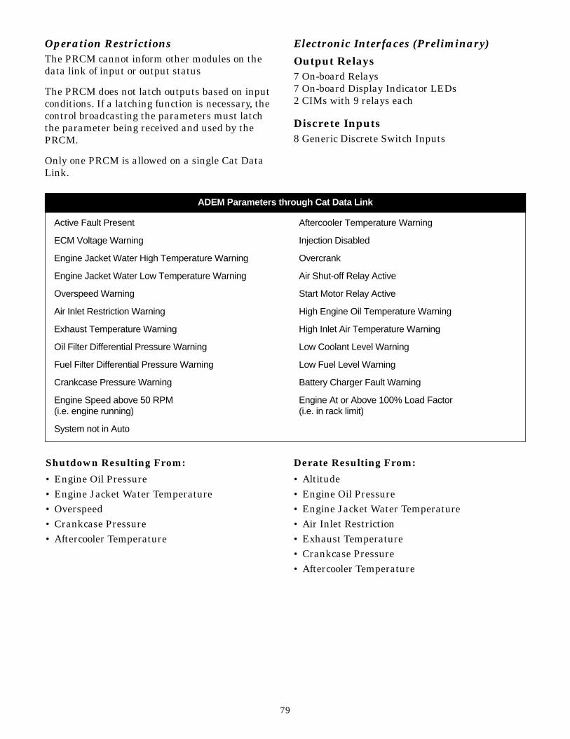
79
Operation RestrictionsThe PRCM cannot inform other modules on thedata link of input or output status
The PRCM does not latch outputs based on inputconditions. If a latching function is necessary, thecontrol broadcasting the parameters must latchthe parameter being received and used by thePRCM.
Only one PRCM is allowed on a single Cat DataLink.
Electronic Interfaces (Preliminary)
Output Relays7 On-board Relays7 On-board Display Indicator LEDs2 CIMs with 9 relays each
Discrete Inputs8 Generic Discrete Switch Inputs
ADEM Parameters through Cat Data Link
Active Fault Present Aftercooler Temperature Warning
ECM Voltage Warning Injection Disabled
Engine Jacket Water High Temperature Warning Overcrank
Engine Jacket Water Low Temperature Warning Air Shut-off Relay Active
Overspeed Warning Start Motor Relay Active
Air Inlet Restriction Warning High Engine Oil Temperature Warning
Exhaust Temperature Warning High Inlet Air Temperature Warning
Oil Filter Differential Pressure Warning Low Coolant Level Warning
Fuel Filter Differential Pressure Warning Low Fuel Level Warning
Crankcase Pressure Warning Battery Charger Fault Warning
Engine Speed above 50 RPM Engine At or Above 100% Load Factor (i.e. engine running) (i.e. in rack limit)
System not in Auto
Shutdown Resulting From:
• Engine Oil Pressure • Engine Jacket Water Temperature • Overspeed • Crankcase Pressure • Aftercooler Temperature
Derate Resulting From:
• Altitude • Engine Oil Pressure • Engine Jacket Water Temperature • Air Inlet Restriction • Exhaust Temperature • Crankcase Pressure • Aftercooler Temperature

80
If the engine is installed at high altitude and repeated notification of high altitude derate is undesirable,the notification of altitude derate may be disabled.
Availability
October 1995
Physical Properties English Units Metric Units
Weight lbs kg
Temperatures:
Maximum Storage Temperature +185°F +85°C
Minimum Storage Temperature -40°F -40°C
Maximum Operating Temperature +158°F +70°C
Minimum Operating Temperature -40°F -40°C
Parameter Being Nominal Total Nominal Nominal Total NominalMeasured Capacitance per Capacitance Resistance per ft Resistance (1500 ft)
ft (m) (1500 ft) (m) @ 20°C @ 20°C
Conductor to 23 µF (75 pF) 0.035 µFConductorConductor to 44 µF (144 pF) 0.066 µF ShieldSingle conductor 4.27 milliOhms 6.41 Ohms series resistance (14.0 milliOhms)(16 AWG,19/29 stranding)
Serial Number
Each PRCM has a serial number on the bottom ofthe flange. It is a five (5) digit number preceded bythe letters “SN”. The Caterpillar Part number willbe on the same flange. It is a seven (7) digitnumber in the following format: “XXX-XXXX”.
Wiring Diagram
Wire and Cable General Specifications
• The wires connected to the PRCM powerconnections (designated B+ and B-) must be atleast 16 AWG.
• The cable connected to the CAT Data Link(designated CDL+ and CDL-) must be 16 AWG,shielded twisted pair cable. Use Belden® 8719(Caterpillar part number 123-2376) orequivalent.
• Maximum CAT Data Link cable and powerconnections ( B+ and B-) wire length is 100 feet.
No terminations or splices allowed on theabove wires, except as noted in theconnection diagrams.
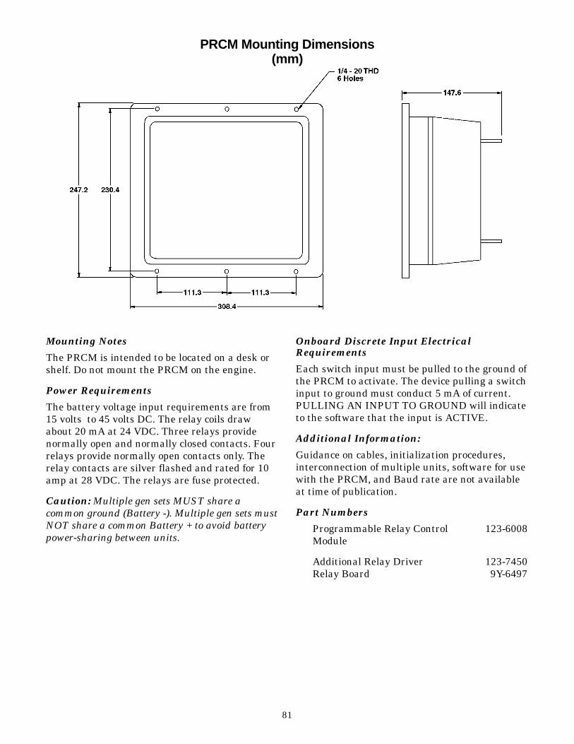
81
PRCM Mounting Dimensions(mm)
Mounting Notes
The PRCM is intended to be located on a desk orshelf. Do not mount the PRCM on the engine.
Power Requirements
The battery voltage input requirements are from15 volts to 45 volts DC. The relay coils drawabout 20 mA at 24 VDC. Three relays providenormally open and normally closed contacts. Fourrelays provide normally open contacts only. Therelay contacts are silver flashed and rated for 10amp at 28 VDC. The relays are fuse protected.
Caution: Multiple gen sets MUST share acommon ground (Battery -). Multiple gen sets mustNOT share a common Battery + to avoid batterypower-sharing between units.
Onboard Discrete Input ElectricalRequirements
Each switch input must be pulled to the ground ofthe PRCM to activate. The device pulling a switchinput to ground must conduct 5 mA of current.PULLING AN INPUT TO GROUND will indicateto the software that the input is ACTIVE.
Additional Information:
Guidance on cables, initialization procedures,interconnection of multiple units, software for usewith the PRCM, and Baud rate are not availableat time of publication.
Part Numbers
Programmable Relay Control 123-6008 Module
Additional Relay Driver 123-7450 Relay Board 9Y-6497
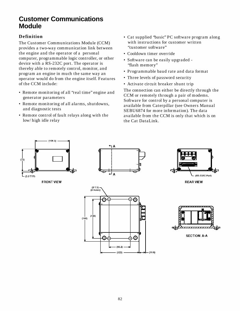
82
Customer CommunicationsModuleDefinitionThe Customer Communications Module (CCM)provides a two-way communication link betweenthe engine and the operator of a personalcomputer, programmable logic controller, or otherdevice with a RS-232C port. The operator isthereby able to remotely control, monitor, andprogram an engine in much the same way anoperator would do from the engine itself. Featuresof the CCM include:
• Remote monitoring of all “real time” engine andgenerator parameters
• Remote monitoring of all alarms, shutdowns,and diagnostic tests
• Remote control of fault relays along with thelow/ high idle relay
• Cat supplied “basic” PC software program alongwith instructions for customer written “customer software”
• Cooldown timer override• Software can be easily upgraded -
“flash memory”• Programmable baud rate and data format• Three levels of password security• Activate circuit breaker shunt tripThe connection can either be directly through theCCM or remotely through a pair of modems.Software for control by a personal computer isavailable from Caterpillar (see Owners ManualSEBU6874 for more information). The dataavailable from the CCM is only that which is onthe Cat DataLink.

83
12 39
17F1
+24
10A
Unit 1
B+ Fused
B- (low current)
CAT Data Link +
CAT Data Link -
DATA +
DATA -
SHEILDNOTE A
CCM
+B
-B
CDL+
CDL-
12
AUX Terminal Strip - located inside EMPC ll panel on left wall
TS1 Terminal Strip - located in generator housing
EMCP ll Genset Control Relay Module terminal
NOTE A: Shield is to be left open at CCM
Physical Properties English Units Metric Units
Weight 1.1 lbs 0.5 kg
Length 5.7 in 145 mm
Width 5.9 in 149 mm
Height 2.9 in 73 mm
Minimum recommended baud rate 9,600
Temperatures:
Maximum Storage Temperature +185°F +85°C
Minimum Storage Temperature -40°F -40°C
Maximum Operating Temperature +158°F +70°C
Minimum Operating Temperature -40°F -40°C
Wiring Diagrams

84
Serial NumberEach CCM has a serial number on the bottom ofthe flange. It is a five (5) digit number preceded bythe letters “SN”. The Caterpillar Part number willbe on the same flange. It is a seven (7) digitnumber in the following format: "XXX-XXXX".
Wiring Diagram
Wire and Cable General Specifications• The wires connected to the CCM power
connections (designated B + and B -) must be atleast 16 AWG.
• The cable connected to the CAT Data Link(designated CDL + and CDL -) must be 16 AWG,shielded twisted pair cable. Use Belden 8719(Caterpillar part number 123-2376) orequivalent.
• Maximum 100 feet, including wire runs betweenany multiple gen sets.
• Maximum total wire length for the RS-232 cableis 50 feet. It should be standard 25 pin “D” typeconnector. Cable must include; transmit,received, DTR, DCD and ground conductors
• Null modem required for direct connectedsystem
No terminations or splices allowed on the abovewires, except as noted in the connection diagrams.
Mounting Notes
The CCM is intended to be located on a desk orshelf. Do not mount the CCM on the engine orwithin the EMCP-II panel.
Battery Power RequirementsThe battery voltage input requirements are from15 to 45 volts DC (24 or 32 volts DC nominal).Power dissipation between the “Battery +” and the“Battery -” is 3.0 W at 24 volts. Caution: Multiplegen sets MUST share a common ground (Battery -). Multiple gen sets must NOT share acommon Battery + to avoid battery power-sharingbetween units.
CCM Battery (Internal)The CCM contains a battery that supplies powerfor internal memory whenever the CCM power isturned off.
Parameter BeingMeasured
Nominal Capacitanceper ft (m)
Total NominalCapacitance
(1500 ft)
Nominal resistance per ft (m) @
20°C
Total NominalResistance (1500 ft)
@ 20°C
Conductor to Conductor
Conductor to Shield
Single conductor seriesresistance (16 AWG,19/29 stranding)
23 µF (75 pF)
44 µF (144 pF)
0.035 F
0.066 F
4.27 milliOhms(14.0 milliOhms)
6.41 Ohms
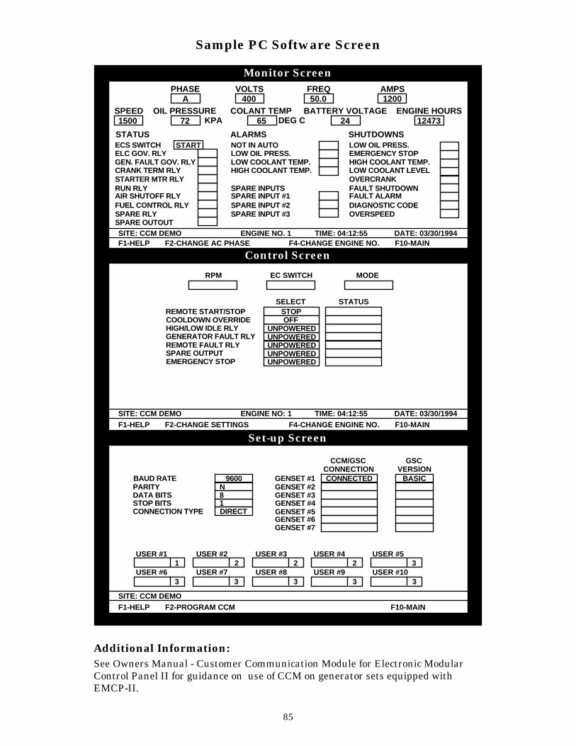
85
Sample PC Software Screen
Additional Information:See Owners Manual - Customer Communication Module for Electronic ModularControl Panel II for guidance on use of CCM on generator sets equipped withEMCP-II.
PHASE VOLTS FREQ AMPS
ENGINE HOURSBATTERY VOLTAGECOLANT TEMPOIL PRESSURESPEED
STATUS ALARMS SHUTDOWNSSTART NOT IN AUTO
LOW OIL PRESS.LOW COOLANT TEMP.HIGH COOLANT TEMP.
SPARE INPUTSSPARE INPUT #1SPARE INPUT #2SPARE INPUT #3
ECS SWITCHELC GOV. RLYGEN. FAULT GOV. RLYCRANK TERM RLYSTARTER MTR RLYRUN RLYAIR SHUTOFF RLYFUEL CONTROL RLYSPARE RLYSPARE OUTOUT
LOW OIL PRESS.EMERGENCY STOPHIGH COOLANT TEMP.LOW COOLANT LEVELOVERCRANKFAULT SHUTDOWNFAULT ALARMDIAGNOSTIC CODEOVERSPEED
KPA DEG C1500 72
A 400 50.0 1200
65 24 12473
F1-HELP F2-CHANGE AC PHASE F4-CHANGE ENGINE NO. F10-MAINSITE: CCM DEMO ENGINE NO. 1 TIME: 04:12:55 DATE: 03/30/1994
F1-HELP F2-CHANGE SETTINGS F4-CHANGE ENGINE NO. F10-MAINSITE: CCM DEMO ENGINE NO: 1 TIME: 04:12:55 DATE: 03/30/1994
F1-HELP F2-PROGRAM CCM F10-MAINSITE: CCM DEMO
RPM EC SWITCH
SELECTSTOPREMOTE START/STOPOFFCOOLDOWN OVERRIDE
UNPOWEREDUNPOWEREDUNPOWEREDUNPOWEREDUNPOWERED
HIGH/LOW IDLE RLYGENERATOR FAULT RLYREMOTE FAULT RLYSPARE OUTPUTEMERGENCY STOP
STATUS
MODE
9600N81DIRECT
BAUD RATEPARITYDATA BITSSTOP BITSCONNECTION TYPE
GENSET #1 CONNECTED BASICCONNECTION
GENSET #2GENSET #3GENSET #4GENSET #5GENSET #6GENSET #7
CCM/GSC GSCVERSION
USER #1
USER #6
USER #2
USER #7
USER #3
USER #8
USER #4
USER #9
USER #5
USER #101
3 3 3 3 3
2 2 2 3
Monitor Screen
Control Screen
Set-up Screen

86
3500B Cooling SystemsThere are several new features of the 3500Bcooling systems. 3500B Marine Engines all haveseparate cooling circuits for their aftercoolers.
• The heavy weight marine engines havethermostats on the aftercooler circuits,controlling the temperature so it never goesbelow 30°C (86°F). They are also designed toallow only treated, fresh water through theiraftercoolers.
• The high performance marine engines pump seawater directly through their aftercoolers and donot use thermostats to control the aftercoolerwater temperature.
• The engine’s performance is tied to thetemperature of the water through theaftercooler. The cooler that water, within certainlimits, the better the fuel efficiency, theemissions, and the life of the engine. This placesa high priority on the proper sizing of theaftercooler circuit heat transfer device (radiator,heat exchanger or keel cooler). The aftercoolercircuit thermostat protects against part loadproblems associated with overcooling.
• The jacket water heat rejection of the 3500B Marine Engine no longer includes theheat rejection of the aftercooler, though the heatrejected by the engine oil cooler is still included.
• The radiator cooled EPG engines deal with theseparate circuits in two ways:
For the ultimate in engine fuelefficiency/emissions, the engine's aftercoolercircuit is expected to be provided by the customer.The customer must provide whatever heattransfer device is most practical to get the lowestaftercooler water temperature year around. Onsome installations this will be a split core radiator,a cooling tower, or a spray pond. In otherinstallations, city water, a well or a submergedpipe cooler will be used. In any case, it is thecustomer's responsibility to provide the coolingmeans for the aftercooler circuit, if ultimateengine performance (lowest aftercooler watertemperature) is needed.
For a more cost effective arrangement, the factorywill provide special radiators with dual inlets andoutlets, so both the jacket water and theaftercooler water are cooled in the same radiatorcore. These radiator arrangements will deliverfairly low aftercooler water temperatures, in allbut extreme conditions. That is, when theengine/generator are not running at full load, atrelatively low ambient air temperatures and if theradiator is oversized. Radiator performance ismore difficult to forecast when operating in thismode. It is recommended that radiatorperformance be obtained from the factory whenusing this cooling strategy, because of therepetitive nature of the calculations:
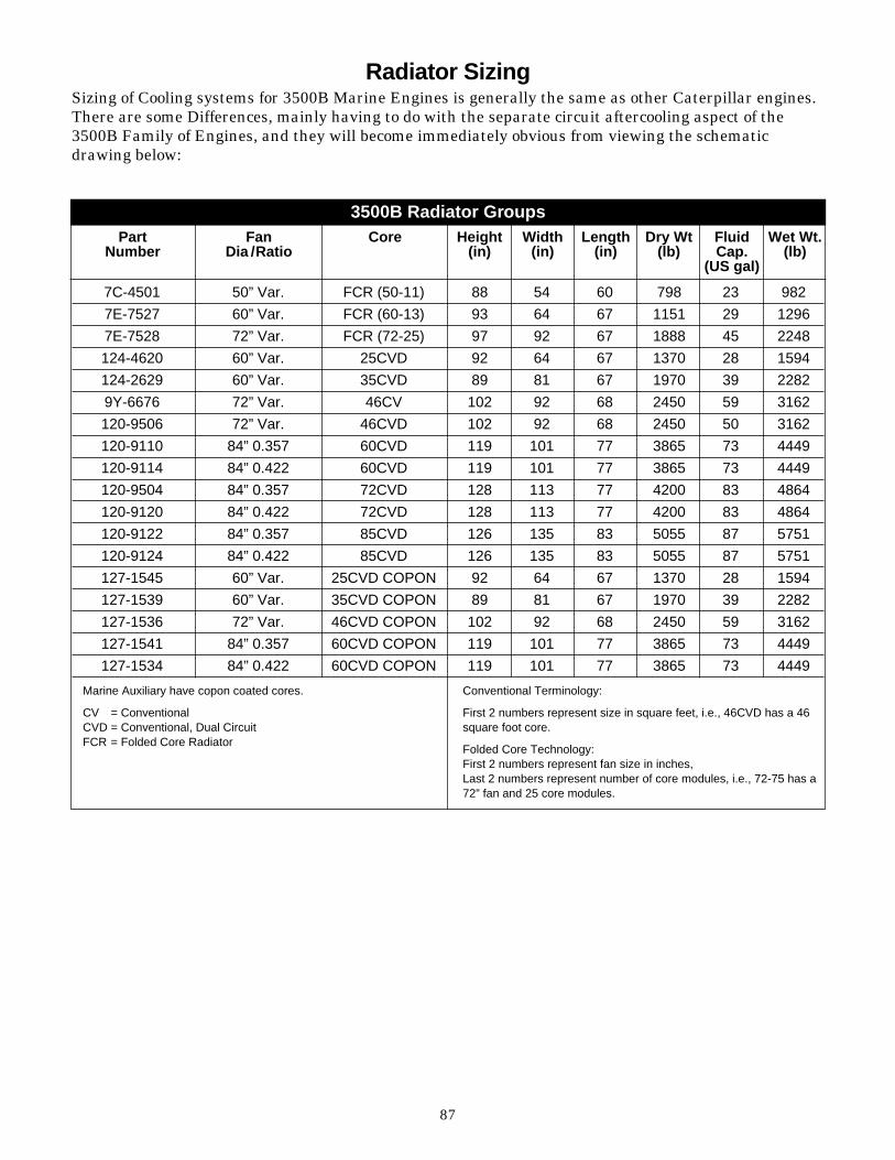
87
3500B Radiator GroupsPart
NumberFan
Dia /RatioCore Height
(in)Width
(in)Length
(in)Dry Wt
(lb)FluidCap.
(US gal)
Wet Wt.(lb)
7C-4501 50” Var. FCR (50-11) 88 54 60 798 23 982
7E-7527 60” Var. FCR (60-13) 93 64 67 1151 29 1296
7E-7528 72” Var. FCR (72-25) 97 92 67 1888 45 2248
124-4620 60” Var. 25CVD 92 64 67 1370 28 1594
124-2629 60” Var. 35CVD 89 81 67 1970 39 2282
9Y-6676 72” Var. 46CV 102 92 68 2450 59 3162
120-9506 72” Var. 46CVD 102 92 68 2450 50 3162
120-9110 84” 0.357 60CVD 119 101 77 3865 73 4449
120-9114 84” 0.422 60CVD 119 101 77 3865 73 4449
120-9504 84” 0.357 72CVD 128 113 77 4200 83 4864
120-9120 84” 0.422 72CVD 128 113 77 4200 83 4864
120-9122 84” 0.357 85CVD 126 135 83 5055 87 5751
120-9124 84” 0.422 85CVD 126 135 83 5055 87 5751
127-1545 60” Var. 25CVD COPON 92 64 67 1370 28 1594
127-1539 60” Var. 35CVD COPON 89 81 67 1970 39 2282
127-1536 72” Var. 46CVD COPON 102 92 68 2450 59 3162
127-1541 84” 0.357 60CVD COPON 119 101 77 3865 73 4449
127-1534 84” 0.422 60CVD COPON 119 101 77 3865 73 4449
Marine Auxiliary have copon coated cores.
CV = ConventionalCVD = Conventional, Dual CircuitFCR = Folded Core Radiator
Conventional Terminology:
First 2 numbers represent size in square feet, i.e., 46CVD has a 46square foot core.
Folded Core Technology:First 2 numbers represent fan size in inches,Last 2 numbers represent number of core modules, i.e., 72-75 has a72” fan and 25 core modules.
Radiator SizingSizing of Cooling systems for 3500B Marine Engines is generally the same as other Caterpillar engines.There are some Differences, mainly having to do with the separate circuit aftercooling aspect of the 3500B Family of Engines, and they will become immediately obvious from viewing the schematicdrawing below:

88
Radiator Sizing Calculation Example3500B dual circuit - refer to 7C-7500 Sizing Chart
3512 - 1360 EkW @ 1800 rpm, Prime, Low NOx
Find Heat Rejection in TMI:
Ta = Tmc _ (Jacket Water Heat Rejection + Aftercooler Heat Rejection x 100)
Effective Heat Load
Where:
Ta = Ambient Temperature
For Prime and Continuos, Tmc = 200°F
For Standby, Tmc = 210°F
Effective Heat Load can be found on Radiator Chart (next page)
Correct Ta for Glycol effect (1.8°F/10% Glycol)
and Altitude Effect (0.5%/200 ft - above 600 ft)
and Air-to-Core Temp Rise Effect (See 7C-7500)
The result is the Ambient Capability.
For Radiator Sizing for cooling of jacket water only, use Jacket Water Heater Rejection in place of(Jacket Water Heat Rejection + Aftercooler Heat Rejection) in the above equation.
For Jacket Water Aftercooled Engines, use Jacket Water Heat Rejection in place of(Jacket Water Heat Rejection + Aftercooler Heat Rejection) in the above equation.
For Folded Core Radiator Sizing use 7C-7500.
For Aftercooler Temperatures for CVD Radiators at part load or at less than maximum ambienttemperature, consult factory.
DM1724 30°C 34,918 25,193
DM1732 60°C 34,918 21,952
DM1740 90°C 34,406 16,890
Add 10%
30°C 38,410 27,712
60°C 38,410 24,147
90°C 37,847 18,579
Data Set A/C Water Temp. Jacket Water HeatRejection (Btu/Min)
Aftercooler HeatRejection (BTU/Min)
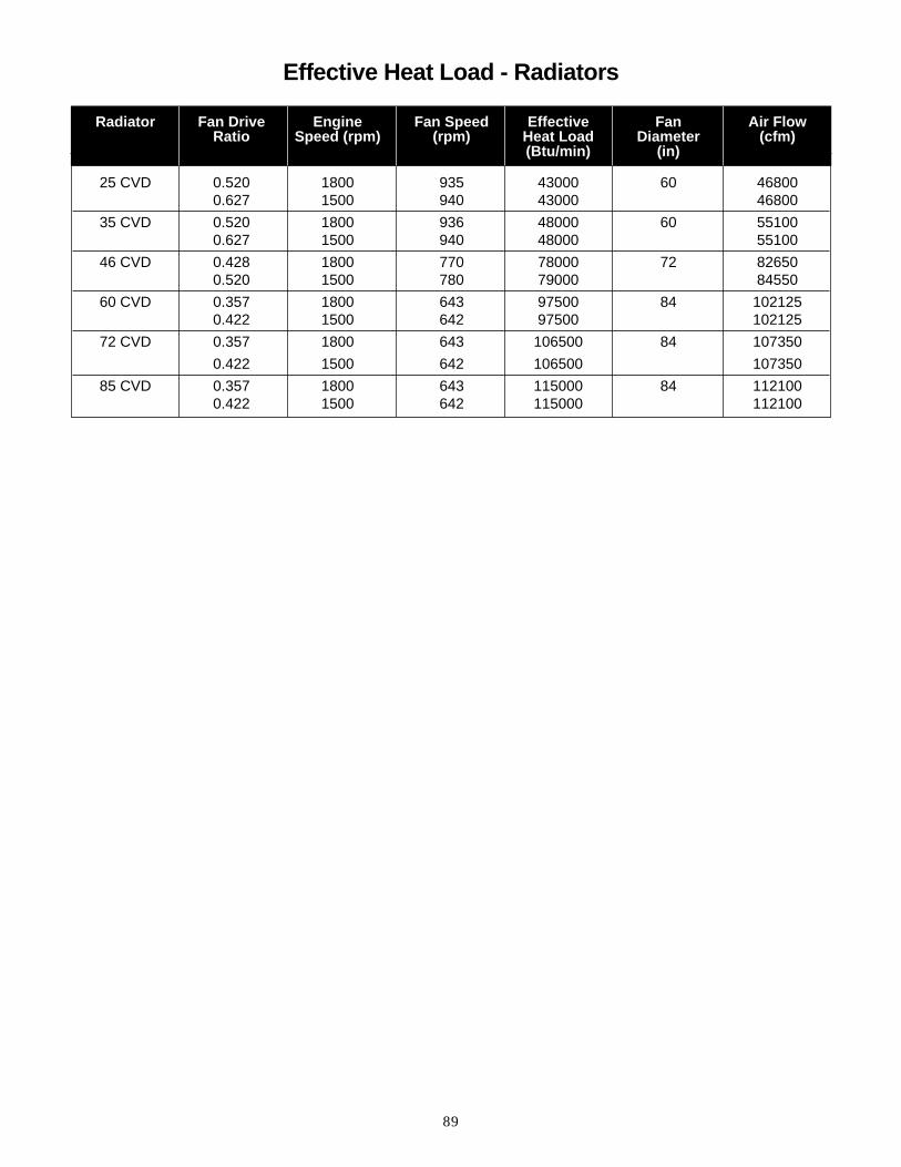
89
25 CVD 0.520 1800 935 43000 60 468000.627 1500 940 43000 46800
35 CVD 0.520 1800 936 48000 60 551000.627 1500 940 48000 55100
46 CVD 0.428 1800 770 78000 72 826500.520 1500 780 79000 84550
60 CVD 0.357 1800 643 97500 84 1021250.422 1500 642 97500 102125
72 CVD 0.357 1800 643 106500 84 107350
0.422 1500 642 106500 107350
85 CVD 0.357 1800 643 115000 84 1121000.422 1500 642 115000 112100
Radiator Fan Drive Engine Fan Speed Effective Fan Air FlowRatio Speed (rpm) (rpm) Heat Load Diameter (cfm)
(Btu/min) (in)
Effective Heat Load - Radiators

90
EPG Engine Cooling Schematic System(Dual Circuit, Single Core Radiator, with auxiliary source for aftercooler circuit coolant)
The information above is to aid thedesigner/installer to use the new features of the3500B cooling system. The most obviousdifference between the B family of engines andtheir predecessors is the use of a separate coolingcircuit for the engine's aftercoolers. Cooler
aftercooler water allows better fuel efficiency andreduced exhaust emissions. There are schematicsof the new systems, a table of system volumes,sample calculations with tables, and graphs of allpumps and heat exchangers.
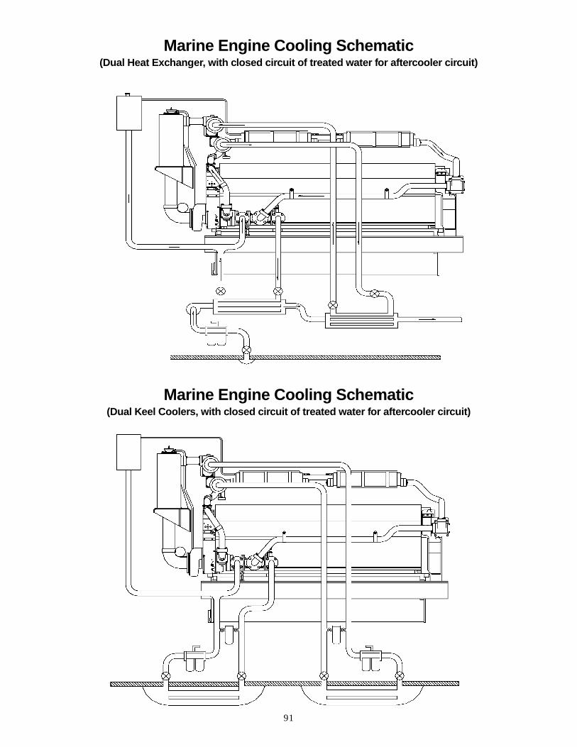
91
Marine Engine Cooling Schematic(Dual Heat Exchanger, with closed circuit of treated water for aftercooler circuit)
Marine Engine Cooling Schematic(Dual Keel Coolers, with closed circuit of treated water for aftercooler circuit)

92
Calculations for Sizing Cooling SystemsChart A: shows all the 3500 heat exchangerperformance curves and their usage, includingshell temperature, shell flow and intended circuit.If your shell temperature and/or flow is expectedto be significantly different than the valuespublished, you will need to generate your ownperformance curves using the Effectiveness Curvesdescribed later.
Chart B: shows the flow rates to use forcalculations, depending on which heat exchanger,engine size, engine rpm, and pump size are used.Flows are based on the following heat exchangerplumbing:
If your plumbing is significantly different thanthat shown, you will need to determine your flowrate by generating a restriction curve for yourplumbing and adding it to the heat exchangerrestriction curves in section B. The intersection ofthis new curve and the applicable pump curve willgive the flow rate of your plumbing configuration.
Pipe Size Pipe (inside dia.) Length No. of 90°
Circuit in. ft. Elbows
Jacket Water 4 or 5 20 6 Shell 1
Separate After- 3 30 8 Cooler Circuit
Sea Water 3 20 8Tubes
3500B Marine EnginesCalculated Aftercooler Circuit Volumes
Model
3508B3512B3516B
Circuit Volume
5.3 U.S. gal6 U.S. gal
7.4 U.S. gal
1Note on Jacket Water Plumbing: Although the Jacket Water pumpinlet and the heat exchanger inlet and outlet are 5 in. ID, 4 in. or 4.5 in. piping may be used for Jacket Water Plumbing if the pipe length and number of elbows does not exceed those listed. If your pipe length and number of elbows are more than those listed, use 5 in. pipe. If the pipe length and the number of elbows are significantly more than those listed, pipe greater than 5 in. may be needed. Plumbing and heat exchanger restriction shoud never be restrictive enough to reduce the flow to less than the lowest point shown on the jacket water pump curve.
Chart C: is for 2 heat exchangers in Series, and shows the flow rates to use for calculations,depending on which heat exchanger, engine size,engine rpm, and pump size are used. Plumbingused is twice the length of pipe and twice thenumber of elbows shown for Chart B.
Chart D: is for three (3) exchangers in series(tube side only, and shows the flow rates to use forcalculations, depending on which heat exchanger,engine size, engine rpm and pump size are used.Plumbing used is three times the length of pipeand three times the number of elbows shown forChart B.
Chart E: is for two (2) heat exchangers inparallel, and shows the the flow rates to use forcalculations, depending on which heat exchanger,engine size, engine rpm and pump size are used.Plumbing used is twice the length of pipe andtwice the number of elbows shown for Chart B.
If NONE appears on a chart for the TMIperformance curve, the flow is outside the rangeof published curves. Curves for these particularflows can be generated using the EffectivenessCurves explained later.

93
JWAC Example
Assumptions: PA2093 - 3512 Marine PropulsionEngine - rated 969.5 kW (1300 bhp) at 1800 rpm CIntermittent from TMI, TM0051, Jacket WaterHeat Rejection = 50330 Btu/min Seawatertemperature is 30°C (86°F). Good engineeringpractice dictates adding 10% safety factor thenominal data:
50330 Btu/min x 1.1 = 55363 Btu/min
Start with the smallest heat exchanger - 4W-4632
From Chart B, shell flow = 400 gpm, and theapplicable performance curve is DM2593. Alsofrom Chart B, seawater flow is 170 gpm with thestandard seawater pump 8N-8466. UsingDM2593, it is seen that heat exchangerperformance for our seawater flow rate andtemperature can be read to be 34,900 Btu/min,well below the required 55,363 Btu/min.
Next try the medium-sized heat exchanger, 4W-4642. From Chart B, shell flow = 400 gpm; theapplicable performance curve is DM2594;seawater flow is 170 gpm. Using DM2594,performance is 50,728 Btu/min, also too small.
Next try the largest heat exchanger, 4W-4652. From Chart B, shell flow = 400 gpm; theapplicable performance curve is TM3833;seawater flow is 170 gpm. Using TM3833,performance is 60,645 Btu/min. This heatexchanger is large enough to cool the 55,363 Btu/min rejected by this engine and rating.Next, make sure the seawater outlet temperatureis less than 54.4°C (130°F) to avoid precipitationof dissolved salts from the sea water which willcoat the heat transfer surfaces of the heatexchanger:
Heat Rejection (Btu/min) 55363∆T = ____________ = _____ = 40.8°FFlow (gpm) x 7.99 170 x 7.99
Sea water outlet temperature = 86°F + 40.8°F = 126.8°F

94
TMI # P/N Shell Temp (°F) Shell Flow (gpm) Typical Shell Circuit
Chart AAvailable Heat Exchanger Performance
DM2593 4W-4632 210 400 JW
TM3968 4W-4632 210 300 JW
DM1290 4W-4632 210 150 90°C SCAC
DM1291 4W-4632 149 150 60°C SCAC
DM1300 4W-4632 106 150 30°C SCAC
DM2594 4W-4642 210 400 JW
TM3969 4W-4642 210 300 JW
DM1292 4W-4642 210 150 90°C SCAC
DM1293 4W-4642 149 150 60°C SCAC
DM1301 4W-4642 106 150 30°C SCAC
TM3833 4W-4652 210 400 JW
DM2595 4W-4652 210 300 JW
DM1294 4W-4652 210 150 90°C SCAC
DM1295 4W-4652 149 150 60°C SCAC
DM2577 4W-4652 106 150 30°C SCAC
For all curves: tube flow range is 55-220 gpm;tube temperature range 41-140°F.
4W-4632 = 3N-8888 = 3N-8889 = 107-17294W-4642 = 3N-8890 = 3N-8891 = 107-17284W-4652 = 3N-8892 = 3N-8893 = 107-1730

95

96

97

98

99
Aftercooler Circuit Expansion TankIf the separate circuit aftercooling (SCAC) coolingsystem is a closed system, an expansion tank isrequired, and should be sized including, the on-engine aftercooler circuit volumes shown. Ifpossible, the expansion tank should provide ashunt line near the aftercooler pump inlet, to helpinsure a positive head on the water pump inlet.The shunt line flow area should be at least 4 timesthe area of all vent lines connected to the tank.
Aftercooler Circuit Air VentingA closed separate circuit aftercooling circuitsystem must be purged of air during filling.
On marine engines, air can be bled out of thesystem by removing the plug on the aftercoolerfront or rear end tank during filling. A bettermethod would be to install a permanent vent linefrom one of the end tanks to the SCAC systemexpansion tank.
The aftercooler system on seawater aftercooled(SWAC) marine engines is an open system anddoes not need to be vented. The seawateraftercooling system should never be vented to thejacketwater system on SWAC engines.
On electric power generator engines, a vent line isinstalled at the factory between the aftercoolerfront end tank and the upper regulator housing.This vent line should be removed if mixing of thejacketwater and aftercooler coolants is notacceptable. If the vent line is removed, othermeans to vent the aftercooler circuit must beprovided.
Vent lines should enter the expansion tank belowthe normal water level, and contain no air traps.
Jacketwater Shunt Tank SystemsIf a jacketwater shunt tank and air separator areused instead of an engine-mounted expansiontank, the shunt tank must be at a sufficient heightto provide enough head for proper air separatoroperation. If the shunt tank is not high enough, anexcess amount of engine outlet water will flow tothe shunt tank through the air separator ventline, and may result in exceeding the shunt tankpressure cap limit.
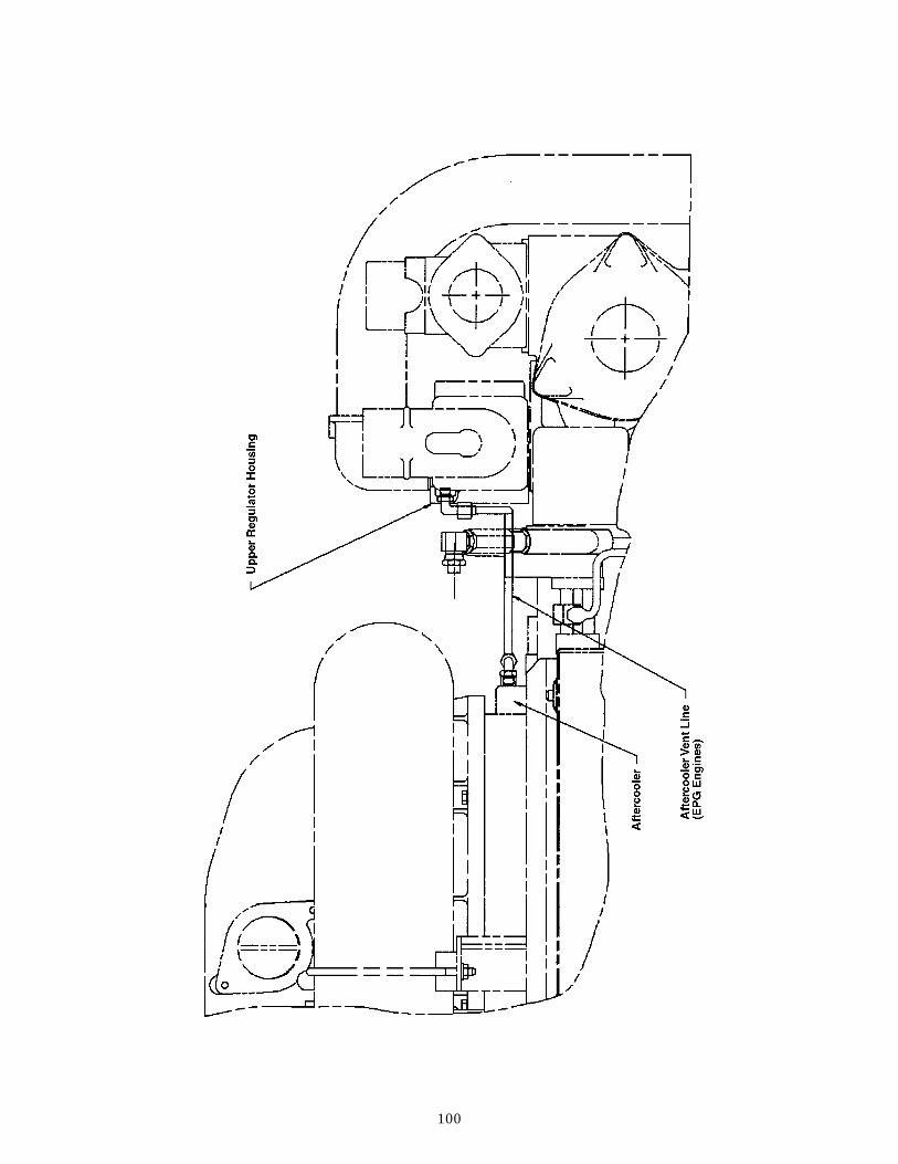
100

101
Separate Circuit Aftercooled (SCAC) Example
Initial assumptions:LA-0272 3516B Marine Prop 1491 kW (2000 hp)@ 1800 rpm A-Cont Set for “Best NOx” FromTMI, DM1491, @ 30°C SCAC: Jacket Water HeatRejection = 31,790 & Aftercooler Heat Rejection =21,724 Btu/min and @ 60°C SCAC: Jacket WaterHeat Rejection = 33,667 & Aftercooler HeatRejection = 18,028 Btu/min.
Add a 10% safety factor to the nominal data:30°C: Jacket Water Heat Rejection = 31,790 x 1.1= 34,969 & Aftercooler Heat Rejection = 21,724 x1.1 = 23,896 Btu/min 60°C: Jacket Water HeatRejection = 33,667 x 1.1 = 37,034 & AftercoolerHeat Rejection = 18,028 x 1.1 = 19,831 Btu/min
Objective: find the smallest pair of heatexchangers that will cool the Jacket Water andcool the Separate Circuit Aftercooler water to 60°C, with a seawater temperature of 30°C(86°F).
Start with two of the smallest heat exchangers,4W-4632. The heat exchangers are in series on theseawater (tube) side, and the seawater flow withpump 8N-8466 can be found on Chart C to be 150 gpm. First look at the heat exchanger used forthe Separate Circuit Aftercooler water. Chart Bshows the Separate Circuit Aftercooler flow rate tobe 150 gpm. Chart A indicates DM1291 is thecorrect heat exchanger performance curve. It isseen that this heat exchanger is capable of onlyabout 17,000 Btu/min, well short of the 19,831 Btu/min required.

102
Next try two of the medium-size heat exchanger,4W-4642. Chart C shows the seawater flow to be150 gpm. Chart B shows the SCAC flow to be 150 gpm. Chart A indicates DM1293 is the correctperformance curve. DM1293 shows a capability of20,947 Btu/min, which is enough to cool the19,831 Btu/min Separate Circuit Aftercooler heatrejection. To find the sea water temperature intothe JW heat exchanger, find the temperature riseand add it to 86°F:
Heat Rejection (Btu/min) 19831∆T = ____________ = _____ = 16.5°FFlow (gpm) x 7.99 150 x 7.99
Seawater outlet temperature = 86°F + 16.5°F = 102.5°F = JW heat exchanger seawater inlet temperature
From Chart B, JW flow is 400 gpm. From Chart Bor Chart A, DM2594 is the performance curve touse. DM2594 shows that 4W-4642 is capable of48,055 Btu/min, which is more than large enoughto cool the 37,034 Btu/min JW heat rejection.
Next make sure the seawater outlet temperaturedoes not exceed 130°F. This is necessary to avoidprecipitation of dissolved salts out of the sea waterwhich will plate out on the heat transfer surfaces,reducing the heat exchanger performance.
Heat Rejection (Btu/min) 37034∆T (deg F) = ____________ = _____ = 30.9°FFlow (gpm) x 7.99 150 x 7.99
Seawater outlet temperature = 102.5°F +30.9°F = 133.4°F
This seawater temperature is over the goal of 130°F. To avoid loss of performance of the heatexchanger, a different sea water pump with higherSCAC flow should be used. The higher seawaterflow may also allow the use of a smaller heatexchanger.
Start again with two of the smallest heatexchanger, 4W-4632.
Chart C shows that sea water pump 4W-6674gives a tube flow of 160 gpm. First look at the heatexchanger used for the SCAC water. From ChartB, SCAC flow rate is 150 gpm. Chart A indicatesDM1291 is the correct heat exchangerperformance curve. It is seen from DM1291 thatthis heat exchanger is capable of only about18,255 Btu/min, well short of the 19,831 Btu/minrequired.
Next look again at two of the medium-size heatexchanger, 4W-4642.
Chart C shows that sea water pump 4W-6674gives a tube flow of 155 gpm. Since two of theseheat exchangers provided adequate cooling with aseawater flow of 150 gpm, they will also beadequate at 155 gpm. All that needs to be done isto check the final sea water outlet temperaturewith the higher sea water flow rate. Calculate thetemperature rise across the SCAC heatexchanger:
Heat Rejection (Btu/min) 19831∆T = ____________ = _____ = 16.0°FFlow (gpm) x 7.99 155 x 7.99
Seawater outlet temperature = 86°F + 16°F= 102°F = JW heat exchanger sea waterinlet temperature
Calculate the final seawater outlet temperatureby finding the temperature rise across the JWheat exchanger:
Heat Rejection (Btu/min) 37034∆T (deg F) = ____________ = _____ = 29.9°FFlow (gpm) x 7.99 155 x 7.99
Final seawater outlet temperature = 102°F +29.9°F = 131.9°F
Since this seawater temperature is still too high,the next larger pump, 9Y-5710, needs to be lookedat.
Start again with 2 of the smallest heat exchanger,4W-4632.
Chart C shows the seawater pump 9Y-5710 givesa tube flow of 245 gpm. To avoid accelerated tubeerosion because of excessive velocity, flow shouldbe kept at 220 gpm or below by adding an orificeor adjustable valve at the pump outlet. Lookingfirst at the heat exchanger used for the SCACwater, Chart B again shows the SCAC flow rate tobe 150 gpm, and Chart A shows DM1291 to be thecorrect heat exchanger performance curve.DM1291 shows the heat rejection capacity to be19,900 Btu/min, which is adequate for cooling therequired 19,831 Btu/min.

103
Next look at the Jacket Water heat exchanger.Calculate the sea water temperature to the JWheat exchanger:
Heat Rejection (Btu/min) 19831∆T = ____________ = _____ = 11.3°FFlow (gpm) x 7.99 220 x 7.99
Jacket Water heat exchanger seawaterinlet temperature = 86°F + 11.3°F =97.3°F
Looking at Chart C, the JW flow is 300 gpm, andTM3968 is the correct performance curve. TM3968shows that this heat exchanger is capable of40,380 Btu/min, which is large enough for therequired 37,304 Btu/min. Now check the final seawater outlet temperature:
Heat Rejection (Btu/min) 37304∆T = ____________ = _____ = 21.2°FFlow (gpm) x 7.99 220 x 7.99
Final sea water outlet temperature =97.3°F + 21.2°F = 118.5°F

104
Sea Water Aftercooled Example
Initial assumptions:LA-0597 3512B Marine Prop 1454 kW (1950 bhp) @ 1835 rpm C-Int
From TMI, DM1835
Jacket Water Heat Rejection = 31051 Btu/min andAftercooler Heat Rejection is 21830 Btu/min
Add 10% safety factor:
Jacket Water Heat Rejection = 1.1 x 31,051 =34,156 and Aftercooler Heat Rejection 1.1 x 21,838= 24,022 Btu/min
Seawater temperature is 30°C (86°F).
In this example, the seawater pump 9Y-5710 isconnected in series with the aftercooler and theheat exchanger. There is also a marine gear coolerconnected in parallel with the aftercooler. Thisparallel flow path increases the total flow, butsince the actual gear cooler water restriction isunknown, it is conservative to assume the flowremains the same as without a gear cooler. Forcalculation purposes, it is also conservative toassume that 40% of the pump flow goes throughthe gear cooler. Using these assumptions, theseawater temperature to the heat exchanger canbe calculated.
Although this rating is 1835 rpm, the 1800 rpmdata can be used. If the engine speed issignificantly different than any of the speedsshown on Charts A-E, the flow rate can beextrapolated or interpolated using the PumpLaws.
Start with the smallest heat exchanger, 4W-4632.
Chart B shows the seawater flow to be 235 gpm,which should be limited to 220 gpm. The seawaterflow through the SWAC is 0.6 x 220 = 132 gpm.
Seawater temperature rise across the aftercooler is:
Heat Rejection (Btu/min) 24022∆T = ____________ = _____ = 22.8°FFlow (gpm) x 7.99 132 x 7.99
Aftercooler seawater outlet temperature =86°F + 22.8°F = 108.8°F
If the marine gear is 95% efficient, 5% of theengine bhp has to be removed by the seawater inthe form of heat: 0.05 x 1950 = 97.5 hp = 4,136 Btu/min = Heat Rejection of the Marine Gear.

105
Seawater flow through the gear cooler is 0.4 x 220= 88 gpm.Seawater temperature rise across the gear cooler is:
Heat Rejection 4136∆T = __________ = _____ = 5.9°FFlow (gpm) x 7.99 88 x 7.99
Gear cooler seawater outlet temperature =86°F + 5.9°F = 91.9°F
Seawater temperature to the heat exchanger is:
132 88(__) 108.8 + (__) 91.9 + 102.0°F220 220
From Chart B, DM2593 is the correct performancecurve to use. From DM2593, the heat rejectioncapacity of this heat exchanger is 38,102 Btu/min,which is large enough for the Jacket Water HeatRejection of 34,156 Btu/min.
Next make sure the final seawater temperaturedoes not exceed 130°F:
Heat Rejection (Btu/min) 34156∆T = ____________ = _____ = 19.4°FFlow (gpm) x 7.99 220 x 7.99
Seawater outlet temperature = 102°F +19.4°F = 121.4°F
Using Effectiveness Data
When any heat exchanger flowrate is outside therange of flows in the published heat exchangerdata, the effectiveness curves can be used todetermine performance.
Heat exchanger restriction curves and pumpperformance curves for all available heatexchangers and pumps are attached. A plumbingrestriction curve should be derived and added tothe heat exchanger restriction curve before theheat exchanger restriction curve is intersectedwith a pump curve to determine flow.
Effectiveness is defined as:
(T shell in - T shell out ) ∆ T shell Effectiveness = ___________ = __________(T shell in - T tubein ) (T shellin - T tube in )
Since Heat Rejection∆T = _______________Flow x Specific Heat x Density
This equation can be rearranged to give heattransfer capacity for a given Effectiveness E:
Heat Rejection = E x Flow x C x (T shell in - T tubein )
For this equation, HEAT REJECTION is inBtu/min, FLOW is in gpm, and Temperatures arein °F. For sea water, C = 7.99; for a 50/50freshwater/glycol mixture, C = 7.31; forfreshwater, C = 8.1
Using this equation, a heat exchangerperformance curve can be generated for anycombination of shell flow, tube flow, shelltemperature, and tube temperature.

106
Emissions Data _ ISO 8179-1ISO Test Cycles
Mode Number 1 2 3 4Cycle E3
% of Rated Speed1
100 91 80 63
% of Rated Power 100 75 50 25
Weighting Factor 0.2 0.5 0.15 0.151See ISO 8179-1 clause 11.5 and clauses 3.4, 3.5 and 3.6 of this international standard
Test Modes and Weighting Factors
7.11
100 100 0.2 7.1 x 0.2 = 1.42
6.021
75 91 0.5 6.02 x 0.5 =3.01
6.21
50 80 0.15 6.2 x 0.15 = 0.93
6.41
25 63 0.15 6.4 x 0.15 = 0.96
NOx(g/hp-hr)
Power(%)
Speed(%)
WeightingFactor Calculations
To comply with ISO 8179-1, an engine must be operated at 100, 75, 50 and 25 percent of rated power, at the speeds tabulated above, and the resulting emissions levels weighted by the weighting factors to arrive at the figure displayed in engine specification sheets.
1 Figures above are offered to illustrate the ISO cycle calculation method only. They are not necessarily representative of any particular engine/s.
Example:
1.42 + 3.01 + 0.93 + 0.96 = 6.321Spec Sheet NOx Rating
@ @ x

107
3508 Jacket Water System Performance DM1297-00
100 170 310 380 450
Ext
ern
al R
estr
icti
on
External Water Flow
g/min
L/min
ft of H2O
m of H2O
240
AC
B
500 17001100 1400800
15
0
30
45
0
3
6
9
12
15
Curve DataCurve Label A B CEngine Speed rpm 1800 1600 1500Pump Speed rpm 2400 2133 2000
External Flow --------------------------External Resistance ---------------------L/min --------------------------Meter of Water -----------------------------
159169180185190201211222232238243254243254264275285291296306317328338349359370
Curve DataCurve Label A B CEngine Speed rpm 1800 1600 1500Pump Speed rpm 2400 2133 2000
External Flow --------------------------External Resistance ---------------------gal/min --------------------------Feet of Water -------------------------------
602640680700720760800840880901920960
1000104010801102112011601200124012801320136014001401
Engine equipped with water cooled exhaustmanifolds or with dry exhaust manifolds.Engine mounted expansion tank.
2W-9726 JW Pump
Drive Ratio 1.33 to 1
For low speed (1300 rpm and below) ratings
Curves indicate maximum allowable externalresistance.
Do not project curves.
39.438.435.8
33.130.227.6
24.922.319.716.714.111.5
8.95.9
37.135.833.531.228.926.2
24.021.719.416.714.4
12.19.87.2
35.833.831.5
29.226.924.622.020.0
17.715.413.511.2
8.97.9
12.011.710.910.1
9.28.4
7.66.86.05.14.33.52.71.81.8
11.310.910.2
9.58.88.0
7.36.65.95.14.4
3.73.02.2
10.910.3
9.6
8.98.27.56.76.1
5.44.74.13.42.72.4

108
3508B Auxiliary Pump Performance TM4143-03
Curve DataCurve Label A B C D EEngine Speed rpm 900 1000 1100 1200 1300Pump Speed rpm 1800 2000 2200 2400 2600
External Flow --------------------------External Resistance ---------------------L/min --------------------------Meter of Water -----------------------------
440450460470480490500510520530540544548550552556560564568572576580584588590600610620630640650660670680690700
Curve DataCurve Label A B C D EEngine Speed rpm 900 1000 1100 1200 1300Pump Speed rpm 1800 2000 2200 2400 2600
External Flow --------------------------External Resistance ---------------------gal/min --------------------------Feet of Water -------------------------------
116119122124127129132135137140143144145146147148149150151152153154155156159161164166169172174177180182185
Self priming pump with 29 mm diameter pumporifice plate
Pump Group 5N-5874, 4W-6674
For low speed (1300 rpm and below) ratings Curves indicate maximum allowable externalresistance.
Do not project curves.
8.07.16.15.04.03.12.2
9.78.97.76.45.34.2
3.3
10.29.58.7
8.17.56.96.35.75.14.43.83.12.42.0 11.5
10.08.56.95.23.51.7
14.213.011.610.0
8.36.54.72.9
26.223.320.016.413.110.2
7.231.829.225.321.017.413.8
10.8
33.531.228.526.624.622.620.718.716.714.412.510.2
7.96.6 37.7
32.827.922.617.111.5
5.6
46.642.738.132.827.221.315.4
9.5
0
Ext
ern
al R
estr
icti
on
External Water Flow
g/min
L/min
ft of H2O
m of H2O
A
0
3
180 200160
600 700
100 140
500400
B
CD
120
E10
20
30
40
6
9
12
15

109
3508B Auxiliary Pump Performance TM4141-03
Curve DataCurve Label A B C DEngine Speed rpm 1200 1500 1600 1800Pump Speed rpm 1600 2000 2133 2400
External Flow --------------------------External Resistance ---------------------L/min --------------------------Meter of Water -----------------------------
375384392400408416425500508516524532540550560570580584590600610620630640650
Curve DataCurve Label A B C DEngine Speed rpm 1200 1500 1600 1800Pump Speed rpm 1600 2000 2133 2400
External Flow --------------------------External Resistance ---------------------gal/min --------------------------Feet of Water -------------------------------
99102106110112132136138139140143145148151153154156159161164166169172
Self priming pump with 29 mm diameter pumporifice plate
Pump Group 5N-5874, 4W-6674
For high speed (1301 - 1800 rpm) ratings Curves indicate maximum allowable externalresistance.
Do not project curves.
7.06.35.64.84.03.12.1
8.97.86.85.85.04.23.3
10.8
9.28.06.75.34.0
2.92.0
12.311.510.0
8.36.75.03.31.7
22.619.415.710.2
6.929.222.3
17.7
13.810.8
35.4
33.530.226.222.017.413.1
9.56.6
40.437.732.827.222.016.410.8
5.6
0
Ext
ern
al R
estr
icti
on
External Water Flow
g/min
L/min
ft of H2O
m of H2O
A
0
3
180 200160
600 700
100 140
500400
B
CD
120
10
20
30
40
6
9
12
15
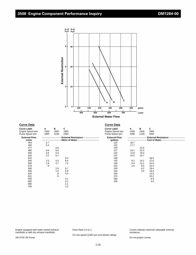
110
Engine equipped with water cooled exhaustmanifolds or with dry exhaust manifolds.
2W-9729 JW Pump
Drive Ratio 2.0 to 1
For low speed (1300 rpm and below) ratings
Curves indicate maximum allowable externalresistance.
Do not project curves.
3508 Engine Component Performance Inquiry DM1284-00
10
0
20
Ext
ern
al R
estr
icti
on
External Water Flow
g/min
L/min
ft of H2O
m of H2O
A
0
3
6
180 200160
600 700
100 140
500400
309
BC
120
Curve DataCurve Label A B CEngine Speed rpm 1500 1600 1800Pump Speed rpm 1995 2128 2394
External Flow --------------------------External Resistance ---------------------L/min --------------------------Metre of Water -----------------------------
454 5.7460 5.4477 6.9480 4.6 6.8500 3.9 5.9520 3.2 5.1522 9.3540 2.5 4.3 8.4560 1.8 3.7 7.5579 .8580 2.9 6.7600 1.9 5.9620 .9 5.0621 .9640 4.1660 3.1680 2.1700 1.2
Curve DataCurve Label A B CEngine Speed rpm 1500 1600 1800Pump Speed rpm 1995 2128 2394
External Flow --------------------------External Resistance ---------------------gal/min --------------------------Feet of Water -------------------------------
120 18.7122 17.7126 22.6127 15.1 22.3132 12.8 19.4137 10.5 16.7138 30.5143 8.2 14.1 27.6148 5.9 12.1 24.6153 2.6 9.5 22.0159 6.2 19.4164 3.0 16.4169 13.5174 10.2180 6.9185 3.9
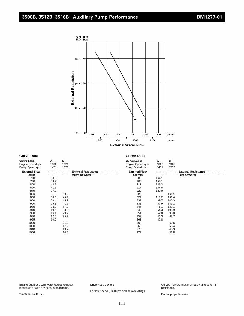
111
3508B, 3512B, 3516B Auxiliary Pump Performance DM1277-01
50
0
100
Ext
ern
al R
estr
icti
on
External Water Flow
g/min
L/min
ft of H2O
m of H2O
0
15
30
260
1000 1100
200 240
900800
15045
220 280 300
A B
Curve DataCurve Label A BEngine Speed rpm 1800 1925Pump Speed rpm 1471 1573
External Flow --------------------------External Resistance ---------------------L/min --------------------------Metre of Water -----------------------------
770 50.0780 48.2800 44.6820 41.1840 37.5856 50.0860 33.9 49.2880 30.4 45.2900 26.8 41.2920 23.2 37.2940 19.6 33.2960 16.1 29.2980 12.6 25.2995 10.0
1000 21.21020 17.21040 13.21056 10.0
Curve DataCurve Label A BEngine Speed rpm 1800 1925Pump Speed rpm 1471 1573
External Flow --------------------------External Resistance ---------------------gal/min --------------------------Feet of Water -------------------------------
203 164.1206 158.1211 146.3217 134.8222 123.0226 164.1227 111.2 161.4232 99.7 148.3238 87.9 135.2243 76.1 122.1248 64.3 108.9254 52.8 95.8259 41.3 82.7263 32.8264 69.6269 56.4275 43.3279 32.8
Engine equipped with water cooled exhaustmanifolds or with dry exhaust manifolds.
2W-9729 JW Pump
Drive Ratio 2.0 to 1
For low speed (1300 rpm and below) ratings
Curves indicate maximum allowable externalresistance.
Do not project curves.

112
Water Temp °C 60 49 38 27 16 5
Cooling Water Flow Heat Transfer Capacity
L/min kW kW kW kW kW kW
Performance Parameters
JW Flow Through Shell: 1514 L/min
JW Press. Drop: 68 kPa
JW Temp to Cooler: 99° C
Curve Limits m/seckPa
Min Flow – Tube Velocity —Min Flow – Pressure Drop 3.3
Max Flow SW– Tube Velocity —Max Flow SW– Pressure Drop 28.8
Max Flow FW– Tube Velocity —Max Flow FW– Pressure Drop —
Water Temp °F 140 120 100 81 61 41
Cooling Water Flow Heat Transfer Capacity
gal/min Btu/min Btu/min Btu/min Btu/min Btu/min Btu/min
Performance Parameters
JW Flow Through Shell: 400 gpm
JW Press. Drop: 10 psi
JW Temp to Cooler: 210° F
Curve Limits ft/secpsi
Min Flow – Tube Velocity —Min Flow – Pressure Drop 0.5
Max Flow SW– Tube Velocity —Max Flow SW– Pressure Drop 4.2
Max Flow FW– Tube Velocity —Max Flow FW– Pressure Drop —
208 243 313 382 448 518 587300 284 365 446 523 604 685400 321 412 504 591 682 774500 354 455 556 652 753 854600 379 488 596 699 808 916700 405 521 637 747 863 978800 424 545 666 781 902 1023833 431 554 677 794 917 1041
55 13819 17800 21724 25478 29459 3338379 16151 20758 25364 29743 34349 38956
106 18255 23430 28662 33610 38785 44017132 20132 25876 31620 37079 42823 48567159 21554 27753 33894 39752 45951 52093185 23032 29629 36226 42482 49079 55619211 24113 30994 37875 44415 51297 58178220 24511 31506 38501 45155 52150 59202
0
2
4
6
8
10
12
0 200 400 600 800 1000
60°
49°
38°
27°
16°
5°
Hea
t T
ran
sfer
Cap
acit
y, k
W x
102
Cooling Water Flow, L/min
0
10
20
30
40
50
60
70
0 50 100 150 200 250
140°
120°
100°
81°
61°
41°
Hea
t T
ran
sfer
Cap
acit
y, B
tu/m
in x
103
Cooling Water Flow, gal/min
Heat Exchanger Data Groups 3N-8888,3N-8889,4W-4632,107-1729 DM2593-00

113
Water Temp °C 60 49 38 27 16 5
Cooling Water Flow Heat Transfer Capacity
L/min kW kW kW kW kW kW
Performance Parameters
JW Flow Through Shell: 1136 L/min
JW Press. Drop: 69 kPa
JW Temp to Cooler: 99° C
Curve Limits m/seckPa
Min Flow – Tube Velocity —Min Flow – Pressure Drop 3.3
Max Flow SW– Tube Velocity —Max Flow SW– Pressure Drop 17.2
Max Flow FW– Tube Velocity —Max Flow FW– Pressure Drop 28.8
Water Temp °F 140 120 100 81 61 41
Cooling Water Flow Heat Transfer Capacity
gal/min Btu/min Btu/min Btu/min Btu/min Btu/min Btu/min
Performance Parameters
JW Flow Through Shell: 300 gpm
JW Press. Drop: 10 psi
JW Temp to Cooler: 210° F
Curve Limits ft/secpsi
Min Flow – Tube Velocity —Min Flow – Pressure Drop 0.5
Max Flow SW– Tube Velocity —Max Flow SW– Pressure Drop 2.5
Max Flow FW– Tube Velocity —Max Flow FW– Pressure Drop 4.2
208 271 334 408 464 533 579300 320 405 489 569 646 710400 361 462 556 648 732 808500 392 501 603 698 788 869600 413 530 639 738 834 919700 429 553 667 773 871 960800 443 572 690 800 900 995833 448 577 696 807 909 1006
55 15412 18995 23203 26388 30312 3292879 18198 23032 27809 32359 36738 40378
106 20530 26274 31620 36852 41629 45951132 22293 28492 34293 39695 44813 49420159 23487 30141 36340 41970 47429 52263185 24397 31449 37932 43960 49534 54595211 25193 32530 39240 45496 51183 56586220 25478 32814 39581 45894 51695 57211
0
2
4
6
8
10
12
0 200 400 600 800 1000
60°
49°
38°
27°
16°
5°
Hea
t T
ran
sfer
Cap
acit
y, k
W x
102
Cooling Water Flow, L/min
0
10
20
30
40
50
60
0 50 100 150 200 250
140°
120°
100°
81°
61°
41°
Hea
t T
ran
sfer
Cap
acit
y, B
tu/m
in x
103
Cooling Water Flow, gal/min
Heat Exchanger Data Groups 3N-8888, 3N-8889, 4W-4632, 107-1729 TM3968-05
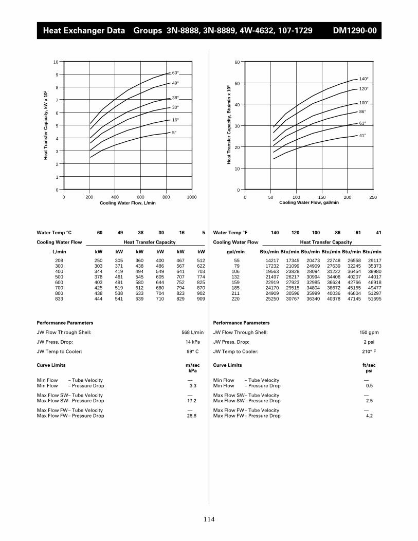
114
Water Temp °C 60 49 38 30 16 5
Cooling Water Flow Heat Transfer Capacity
L/min kW kW kW kW kW kW
Performance Parameters
JW Flow Through Shell: 568 L/min
JW Press. Drop: 14 kPa
JW Temp to Cooler: 99° C
Curve Limits m/seckPa
Min Flow – Tube Velocity —Min Flow – Pressure Drop 3.3
Max Flow SW– Tube Velocity —Max Flow SW– Pressure Drop 17.2
Max Flow FW– Tube Velocity —Max Flow FW– Pressure Drop 28.8
Water Temp °F 140 120 100 86 61 41
Cooling Water Flow Heat Transfer Capacity
gal/min Btu/min Btu/min Btu/min Btu/min Btu/min Btu/min
Performance Parameters
JW Flow Through Shell: 150 gpm
JW Press. Drop: 2 psi
JW Temp to Cooler: 210° F
Curve Limits ft/secpsi
Min Flow – Tube Velocity —Min Flow – Pressure Drop 0.5
Max Flow SW– Tube Velocity —Max Flow SW– Pressure Drop 2.5
Max Flow FW– Tube Velocity —Max Flow FW– Pressure Drop 4.2
208 250 305 360 400 467 512300 303 371 438 486 567 622400 344 419 494 549 641 703500 378 461 545 605 707 774600 403 491 580 644 752 825700 425 519 612 680 794 870800 438 538 633 704 823 902833 444 541 639 710 829 909
55 14217 17345 20473 22748 26558 2911779 17232 21099 24909 27639 32245 35373
106 19563 23828 28094 31222 36454 39980132 21497 26217 30994 34406 40207 44017159 22919 27923 32985 36624 42766 46918185 24170 29515 34804 38672 45155 49477211 24909 30596 35999 40036 46804 51297220 25250 30767 36340 40378 47145 51695
0
1
2
3
4
5
6
7
8
9
10
0 200 400 600 800 1000
60°
49°
38°
30°
16°
5°
Hea
t T
ran
sfer
Cap
acit
y, k
W x
102
Cooling Water Flow, L/min
0
10
20
30
40
50
60
0 50 100 150 200 250
140°
120°
100°
86°
61°
41°
Hea
t T
ran
sfer
Cap
acit
y, B
tu/m
in x
103
Cooling Water Flow, gal/min
Heat Exchanger Data Groups 3N-8888, 3N-8889, 4W-4632, 107-1729 DM1290-00

115
Heat Exchanger Data Groups 3N-8888, 3N-8889, 4W-4632, 107-1729 DM1291-00
Water Temp °C 60 49 38 30 16 5
Cooling Water Flow Heat Transfer Capacity
L/min kW kW kW kW kW kW
Performance Parameters
JW Flow Through Shell: 568 L/min
JW Press. Drop: 14 kPa
JW Temp to Cooler: 65° C
Curve Limits m/seckPa
Min Flow – Tube Velocity — Min Flow – Pressure Drop 3.3
Max Flow SW– Tube Velocity —Max Flow SW– Pressure Drop 17.2
Max Flow FW– Tube Velocity —Max Flow FW– Pressure Drop 28.8
Water Temp °F 140 120 100 86 61 41
Cooling Water Flow Heat Transfer Capacity
gal/min Btu/min Btu/min Btu/min Btu/min Btu/min Btu/min
Performance Parameters
JW Flow Through Shell: 150 gpm
JW Press. Drop: 2 psi
JW Temp to Cooler: 149° F
Curve Limits ft/secpsi
Min Flow – Tube Velocity —Min Flow – Pressure Drop 0.5
Max Flow SW– Tube Velocity —Max Flow SW– Pressure Drop 2.5
Max Flow FW– Tube Velocity —Max Flow FW– Pressure Drop 4.2
208 30 89 148 190 257 300300 38 110 183 235 319 372400 43 126 211 270 366 427500 47 138 230 295 400 466600 51 150 245 315 426 496700 53 154 257 330 447 521800 55 161 269 345 467 545833 56 164 273 350 474 553
55 1706 5061 8417 10805 14616 1706179 2161 6256 10407 13364 18141 21156
106 2445 7166 12000 15355 20814 24283132 2673 7848 13080 16777 22748 26501159 2900 8530 13933 17914 24227 28207185 3014 8758 14616 18767 25421 29629211 3128 9156 15298 19620 26558 30994220 3185 9327 15525 19904 26956 31449
0
1
2
3
4
5
6
0 200 400 600 800 1000
60°
49°
38°
30°
16°
5°
Hea
t T
ran
sfer
Cap
acit
y, k
W x
102
Cooling Water Flow, L/min
0
5
10
15
20
25
30
35
0 50 100 150 200 250
140°
120°
100°
86°
61°
41°
Hea
t T
ran
sfer
Cap
acit
y, B
tu/m
in x
103
Cooling Water Flow, gal/min
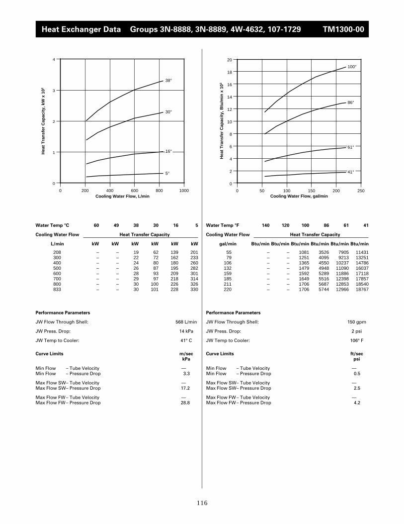
116
Heat Exchanger Data Groups 3N-8888, 3N-8889, 4W-4632, 107-1729 TM1300-00
Water Temp °C 60 49 38 30 16 5
Cooling Water Flow Heat Transfer Capacity
L/min kW kW kW kW kW kW
Performance Parameters
JW Flow Through Shell: 568 L/min
JW Press. Drop: 14 kPa
JW Temp to Cooler: 41° C
Curve Limits m/seckPa
Min Flow – Tube Velocity —Min Flow – Pressure Drop 3.3
Max Flow SW– Tube Velocity —Max Flow SW– Pressure Drop 17.2
Max Flow FW– Tube Velocity —Max Flow FW– Pressure Drop 28.8
Water Temp °F 140 120 100 86 61 41
Cooling Water Flow Heat Transfer Capacity
gal/min Btu/min Btu/min Btu/min Btu/min Btu/min Btu/min
Performance Parameters
JW Flow Through Shell: 150 gpm
JW Press. Drop: 2 psi
JW Temp to Cooler: 106° F
Curve Limits ft/secpsi
Min Flow – Tube Velocity —Min Flow – Pressure Drop 0.5
Max Flow SW– Tube Velocity —Max Flow SW– Pressure Drop 2.5
Max Flow FW– Tube Velocity —Max Flow FW– Pressure Drop 4.2
208 – – 19 62 139 201300 – – 22 72 162 233400 – – 24 80 180 260500 – – 26 87 195 282600 – – 28 93 209 301700 – – 29 97 218 314800 – – 30 100 226 326833 – – 30 101 228 330
55 – – 1081 3526 7905 1143179 – – 1251 4095 9213 13251
106 – – 1365 4550 10237 14786132 – – 1479 4948 11090 16037159 – – 1592 5289 11886 17118185 – – 1649 5516 12398 17857211 – – 1706 5687 12853 18540220 – – 1706 5744 12966 18767
0
1
2
3
4
0 200 400 600 800 1000
38°
30°
16°
5°
Hea
t T
ran
sfer
Cap
acit
y, k
W x
102
Cooling Water Flow, L/min
0
2
4
6
8
10
12
14
16
18
20
0 50 100 150 200 250
100°
86°
61°
41°
Hea
t T
ran
sfer
Cap
acit
y, B
tu/m
in x
103
Cooling Water Flow, gal/min

117
Heat Exchanger Data Groups 3N-8890, 3N-8891, 4W-4642, 107-1728 DM2594-00
Water Temp °C 60 49 38 27 16 5
Cooling Water Flow Heat Transfer Capacity
L/min kW kW kW kW kW kW
Performance Parameters
JW Flow Through Shell: 1514 L/min
JW Press. Drop: 57 kPa
JW Temp to Cooler: 99° C
Curve Limits m/seckPa
Min Flow – Tube Velocity —Min Flow – Pressure Drop 2.1
Max Flow SW– Tube Velocity —Max Flow SW– Pressure Drop 2.3
Max Flow FW– Tube Velocity —Max Flow FW– Pressure Drop 4.0
Water Temp °F 140 120 100 81 61 41
Cooling Water Flow Heat Transfer Capacity
gal/min Btu/min Btu/min Btu/min Btu/min Btu/min Btu/min
Performance Parameters
JW Flow Through Shell: 400 gpm
JW Press. Drop: 8 psi
JW Temp to Cooler: 210° F
Curve Limits ft/secpsi
Min Flow – Tube Velocity —Min Flow – Pressure Drop 0.3
Max Flow SW– Tube Velocity —Max Flow SW– Pressure Drop 2.3
Max Flow FW– Tube Velocity —Max Flow FW– Pressure Drop 4.0
208 287 369 452 530 612 694300 346 445 544 638 737 836400 398 512 625 733 847 961500 435 559 683 801 925 1050600 472 606 741 869 1004 1138700 501 644 787 923 1066 1210800 523 673 822 964 1113 1263833 531 682 834 978 1129 1281
55 16322 20985 25705 30141 34804 3946879 19677 25307 30937 36283 41913 47543
106 22634 29117 35544 41686 48169 54652132 24738 31790 38842 45553 52605 59713159 26843 34463 42141 49420 57097 64718185 28492 36624 44757 52491 60623 68813211 29743 38273 46747 54823 63296 71827220 30198 38785 47429 55619 64206 72850
0
2
4
6
8
10
12
14
0 200 400 600 800 1000
60°
49°
38°
27°
16°
5°
Hea
t T
ran
sfer
Cap
acit
y, k
W x
102
Cooling Water Flow, L/min
0
10
20
30
40
50
60
70
80
0 50 100 150 200 250
140°
120°
100°
81°
61°
41°
Hea
t T
ran
sfer
Cap
acit
y, B
tu/m
in x
103
Cooling Water Flow, gal/min
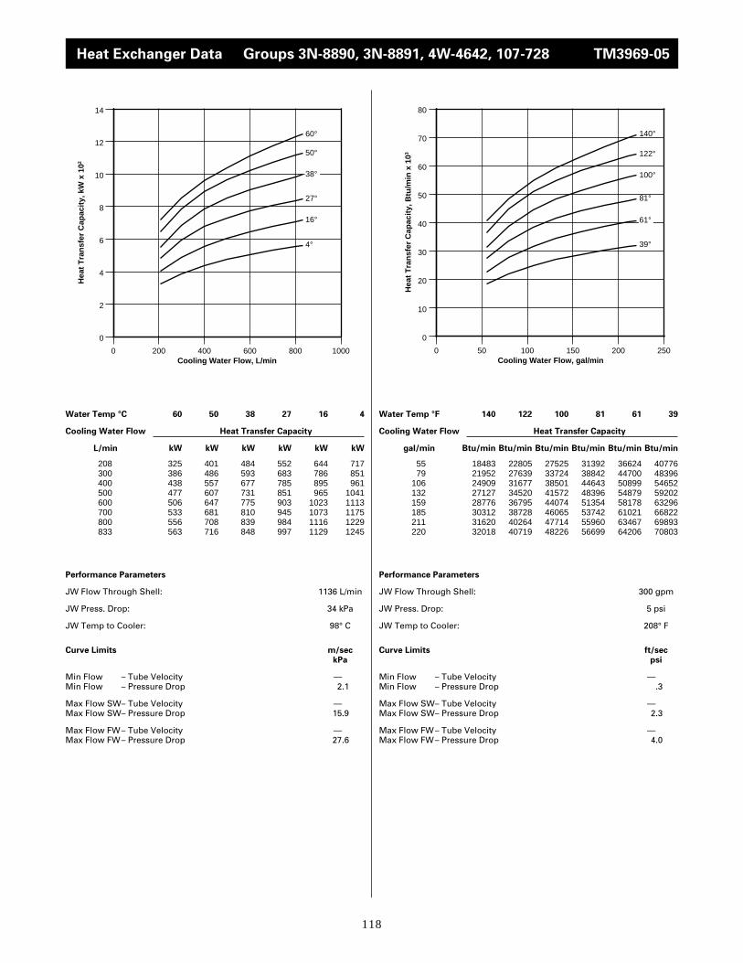
118
Heat Exchanger Data Groups 3N-8890, 3N-8891, 4W-4642, 107-728 TM3969-05
Water Temp °C 60 50 38 27 16 4
Cooling Water Flow Heat Transfer Capacity
L/min kW kW kW kW kW kW
Performance Parameters
JW Flow Through Shell: 1136 L/min
JW Press. Drop: 34 kPa
JW Temp to Cooler: 98° C
Curve Limits m/seckPa
Min Flow – Tube Velocity —Min Flow – Pressure Drop 2.1
Max Flow SW– Tube Velocity —Max Flow SW– Pressure Drop 15.9
Max Flow FW– Tube Velocity —Max Flow FW– Pressure Drop 27.6
Water Temp °F 140 122 100 81 61 39
Cooling Water Flow Heat Transfer Capacity
gal/min Btu/min Btu/min Btu/min Btu/min Btu/min Btu/min
Performance Parameters
JW Flow Through Shell: 300 gpm
JW Press. Drop: 5 psi
JW Temp to Cooler: 208° F
Curve Limits ft/secpsi
Min Flow – Tube Velocity —Min Flow – Pressure Drop .3
Max Flow SW– Tube Velocity —Max Flow SW– Pressure Drop 2.3
Max Flow FW– Tube Velocity —Max Flow FW– Pressure Drop 4.0
208 325 401 484 552 644 717300 386 486 593 683 786 851400 438 557 677 785 895 961500 477 607 731 851 965 1041600 506 647 775 903 1023 1113700 533 681 810 945 1073 1175800 556 708 839 984 1116 1229833 563 716 848 997 1129 1245
55 18483 22805 27525 31392 36624 4077679 21952 27639 33724 38842 44700 48396
106 24909 31677 38501 44643 50899 54652132 27127 34520 41572 48396 54879 59202159 28776 36795 44074 51354 58178 63296185 30312 38728 46065 53742 61021 66822211 31620 40264 47714 55960 63467 69893220 32018 40719 48226 56699 64206 70803
0
2
4
6
8
10
12
14
0 200 400 600 800 1000
60°
50°
38°
27°
16°
4°
Hea
t T
ran
sfer
Cap
acit
y, k
W x
102
Cooling Water Flow, L/min
0
10
20
30
40
50
60
70
80
0 50 100 150 200 250
140°
122°
100°
81°
61°
39°
Hea
t T
ran
sfer
Cap
acit
y, B
tu/m
in x
103
Cooling Water Flow, gal/min

119
Heat Exchanger Data Groups 3N-8890, 3N-8891, 4W-4642, 107-728 TM1292-00
Water Temp °C 60 49 38 30 16 5
Cooling Water Flow Heat Transfer Capacity
L/min kW kW kW kW kW kW
Performance Parameters
JW Flow Through Shell: 568 L/min
JW Press. Drop: 10 kPa
JW Temp to Cooler: 99° C
Curve Limits m/seckPa
Min Flow – Tube Velocity —Min Flow – Pressure Drop 2.1
Max Flow SW– Tube Velocity —Max Flow SW– Pressure Drop 15.9
Max Flow FW– Tube Velocity —Max Flow FW– Pressure Drop 27.6
Water Temp °F 140 120 100 86 61 41
Cooling Water Flow Heat Transfer Capacity
gal/min Btu/min Btu/min Btu/min Btu/min Btu/min Btu/min
Performance Parameters
JW Flow Through Shell: 150 gpm
JW Press. Drop: 1 psi
JW Temp to Cooler: 210° F
Curve Limits ft/secpsi
Min Flow – Tube Velocity —Min Flow – Pressure Drop .3
Max Flow SW– Tube Velocity —Max Flow SW– Pressure Drop 2.3
Max Flow FW– Tube Velocity —Max Flow FW– Pressure Drop 4.0
208 297 362 428 475 555 608300 358 433 513 571 664 731400 403 488 576 641 737 822500 441 534 630 700 816 896600 469 568 672 746 869 956700 496 600 710 790 920 1009800 516 629 743 825 964 1057833 522 638 752 839 978 1074
55 16890 20587 24340 27013 31563 3457779 20359 24625 29174 32473 37762 41572
106 22919 27753 32757 36454 41913 46747132 25080 30369 35828 39809 46406 50955159 26672 32302 38217 42425 49420 54368185 28207 34122 40378 44927 52320 57382211 29345 35771 42254 46918 54823 60111220 29686 36283 42766 47714 55619 61078
0
2
4
6
8
10
12
0 200 400 600 800 1000
60°
49°
38°
30°
16°
5°
Hea
t T
ran
sfer
Cap
acit
y, k
W x
102
Cooling Water Flow, L/min
0
10
20
30
40
50
60
70
0 50 100 150 200 250
140°
120°
100°
86°
61°
41°
Hea
t T
ran
sfer
Cap
acit
y, B
tu/m
in x
103
Cooling Water Flow, gal/min

120
Heat Exchanger Data Groups 3N-8890, 3N8891, 4W-4642, 107-1728 DM1293-00
Water Temp °C 60 49 38 30 16 5
Cooling Water Flow Heat Transfer Capacity
L/min kW kW kW kW kW kW
Performance Parameters
JW Flow Through Shell: 568 L/min
JW Press. Drop: 10 kPa
JW Temp to Cooler: 65° C
Curve Limits m/seckPa
Min Flow – Tube Velocity —Min Flow – Pressure Drop 2.1
Max Flow SW– Tube Velocity —Max Flow SW– Pressure Drop 15.9
Max Flow FW– Tube Velocity —Max Flow FW– Pressure Drop 27.6
Water Temp °F 140 120 100 86 61 41
Cooling Water Flow Heat Transfer Capacity
gal/min Btu/min Btu/min Btu/min Btu/min Btu/min Btu/min
Performance Parameters
JW Flow Through Shell: 150 gpm
JW Press. Drop: 1 psi
JW Temp to Cooler: 149° F
Curve Limits ft/secpsi
Min Flow – Tube Velocity —Min Flow – Pressure Drop .3
Max Flow SW– Tube Velocity —Max Flow SW– Pressure Drop 2.3
Max Flow FW– Tube Velocity —Max Flow FW– Pressure Drop 4.0
208 35 103 172 220 298 348300 45 131 218 280 380 443400 50 152 251 322 434 507500 55 168 275 353 473 552600 61 178 292 376 502 587700 63 184 307 393 528 616800 65 190 316 405 549 640833 66 192 320 410 555 648
55 1990 5858 9782 12511 16947 1979179 2559 7450 12398 15924 21611 25193
106 2843 8644 14274 18312 24682 28833132 3128 9554 15639 20075 26899 31392159 3469 10123 16606 21383 28549 33383185 3583 10464 17459 22350 30027 35032211 3697 10805 17971 23032 31222 36397220 3753 10919 18198 23317 31563 36852
0
1
2
3
4
5
6
7
0 200 400 600 800 1000
60°
49°
38°
30°
16°
5°
Hea
t T
ran
sfer
Cap
acit
y, k
W x
102
Cooling Water Flow, L/min
0
5
10
15
20
25
30
35
40
0 50 100 150 200 250
140°
120°
100°
86°
61°
41°
Hea
t T
ran
sfer
Cap
acit
y, B
tu/m
in x
103
Cooling Water Flow, gal/min

121
Heat Exchanger Data Groups 3N-8890, 3N-8891, 4W4642, 107-1728 DM2576-00
Water Temp °C 60 49 38 30 16 5
Cooling Water Flow Heat Transfer Capacity
L/min kW kW kW kW kW kW
Performance Parameters
JW Flow Through Shell: 568 L/min
JW Press. Drop: 10 kPa
JW Temp to Cooler: 41° C
Curve Limits m/seckPa
Min Flow – Tube Velocity —Min Flow – Pressure Drop 2.1
Max Flow SW– Tube Velocity —Max Flow SW– Pressure Drop 16.0
Max Flow FW– Tube Velocity —Max Flow FW– Pressure Drop —
Water Temp °F 140 120 100 86 61 41
Cooling Water Flow Heat Transfer Capacity
gal/min Btu/min Btu/min Btu/min Btu/min Btu/min Btu/min
Performance Parameters
JW Flow Through Shell: 150 gpm
JW Press. Drop: 1 psi
JW Temp to Cooler: 106° F
Curve Limits ft/secpsi
Min Flow – Tube Velocity —Min Flow – Pressure Drop 0.3
Max Flow SW– Tube Velocity —Max Flow SW– Pressure Drop 2.3
Max Flow FW– Tube Velocity —Max Flow FW– Pressure Drop —
208 – – 22 73 165 239300 – – 26 86 194 280400 – – 29 97 218 314500 – – 31 105 235 340600 – – 33 111 250 362700 – – 35 116 262 378800 – – 36 120 271 391833 – – 37 122 274 395
55 – – 1251 4152 9384 1359279 – – 1479 4891 11033 15924
106 – – 1649 5516 12398 17857132 – – 1763 5971 13364 19336159 – – 1877 6313 14217 20587185 – – 1990 6597 14900 21497211 – – 2047 6824 15412 22236220 – – 2104 6938 15582 22464
0
1
2
3
4
5
0 200 400 600 800 1000
38°
30°
16°
5°
Hea
t T
ran
sfer
Cap
acit
y, k
W x
102
Cooling Water Flow, L/min
0
5
10
15
20
25
0 50 100 150 200 250
100°
86°
61°
41°
Hea
t T
ran
sfer
Cap
acit
y, B
tu/m
in x
103
Cooling Water Flow, gal/min

122
Heat Exchanger Data Groups 3N-8892, 3N-8893, 4W4652, 107-1730 TM3833-06
Water Temp °C 60 50 38 27 16 4
Cooling Water Flow Heat Transfer Capacity
L/min kW kW kW kW kW kW
Performance Parameters
JW Flow Through Shell: 1514 L/min
JW Press. Drop: 91 kPa
JW Temp to Cooler: 98° C
Curve Limits m/seckPa
Min Flow – Tube Velocity —Min Flow – Pressure Drop 2.1
Max Flow SW– Tube Velocity —Max Flow SW– Pressure Drop 19.3
Max Flow FW– Tube Velocity —Max Flow FW– Pressure Drop 34.4
Water Temp °F 136 122 100 81 61 39
Cooling Water Flow Heat Transfer Capacity
gal/min Btu/min Btu/min Btu/min Btu/min Btu/min Btu/min
Performance Parameters
JW Flow Through Shell: 400 gpm
JW Press. Drop: 13 psi
JW Temp to Cooler: 208° F
Curve Limits ft/secpsi
Min Flow – Tube Velocity —Min Flow – Pressure Drop 0.3
Max Flow SW– Tube Velocity —Max Flow SW– Pressure Drop 2.8
Max Flow FW– Tube Velocity —Max Flow FW– Pressure Drop 5.0
208 360 459 550 668 754 853300 449 580 697 812 911 1018400 524 671 809 927 1038 1164500 577 730 881 1009 1129 1280600 615 777 940 1078 1208 1383700 650 817 991 1139 1280 1479800 678 852 1037 1196 1347 1569833 686 863 1050 1213 1368 1597
55 20473 26103 31278 37989 42880 4851079 25535 32985 39638 46178 51808 57894
106 29800 38160 46008 52718 59031 66197132 32814 41515 50102 57382 64206 72793159 34975 44188 53458 61306 68699 78651185 36965 46463 56358 64775 72793 84111211 38558 48453 58974 68016 76604 89229220 39013 49079 59713 68983 77798 90821
0
2
4
6
8
10
12
14
16
18
0 200 400 600 800 1000
60°
50°
38°
27°
16°
4°
Hea
t T
ran
sfer
Cap
acit
y, k
W x
102
Cooling Water Flow, L/min
0
10
20
30
40
50
60
70
80
90
100
0 50 100 150 200 250
136°
122°
100°
81°
61°
39°
Hea
t T
ran
sfer
Cap
acit
y, B
tu/m
in x
103
Cooling Water Flow, gal/min

123
Heat Exchanger Data Groups 3N-8892, 3N-8893, 4W4652, 107-1730 DM2595-00
Water Temp °C 60 49 38 27 16 5
Cooling Water Flow Heat Transfer Capacity
L/min kW kW kW kW kW kW
Performance Parameters
JW Flow Through Shell: 1136 L/min
JW Press. Drop: 54 kPa
JW Temp to Cooler: 99° C
Curve Limits m/seckPa
Min Flow – Tube Velocity —Min Flow – Pressure Drop 2.1
Max Flow SW– Tube Velocity —Max Flow SW– Pressure Drop 19.3
Max Flow FW– Tube Velocity —Max Flow FW– Pressure Drop 34.4
Water Temp °F 140 120 100 81 61 41
Cooling Water Flow Heat Transfer Capacity
gal/min Btu/min Btu/min Btu/min Btu/min Btu/min Btu/min
Performance Parameters
JW Flow Through Shell: 300 gpm
JW Press. Drop: 8 psi
JW Temp to Cooler: 210° F
Curve Limits ft/secpsi
Min Flow – Tube Velocity —Min Flow – Pressure Drop 0.3
Max Flow SW– Tube Velocity —Max Flow SW– Pressure Drop 2.8
Max Flow FW– Tube Velocity —Max Flow FW– Pressure Drop 5.0
208 315 405 495 580 670 –300 381 490 599 703 812 –400 439 565 690 810 935 –500 484 622 760 891 1029 –600 522 671 821 962 1112 –700 553 710 868 1018 1176 –800 575 739 903 1059 1223 –833 586 753 920 1079 1247 –
55 17914 23032 28151 32985 38103 –79 21667 27866 34065 39980 46178 –
106 24966 32131 39240 46065 53173 –132 27525 35373 43221 50671 58519 –159 29686 38160 46690 54709 63239 –185 31449 40378 49363 57894 66879 –211 32700 42027 51354 60225 69552 –220 33326 42823 52320 61363 70917 –
0
2
4
6
8
10
12
14
0 200 400 600 800 1000
60°
49°
38°
27°
16°
Hea
t T
ran
sfer
Cap
acit
y, k
W x
102
Cooling Water Flow, L/min
0
10
20
30
40
50
60
70
80
0 50 100 150 200 250
140°
120°
100°
81°
61°
Hea
t T
ran
sfer
Cap
acit
y, B
tu/m
in x
103
Cooling Water Flow, gal/min

124
Heat Exchanger Data Groups 3N-8892, 3N-8893, 4W-4652, 107-1730 DM1294-00
Water Temp °C 60 49 38 30 16 5
Cooling Water Flow Heat Transfer Capacity
L/min kW kW kW kW kW kW
Performance Parameters
JW Flow Through Shell: 568 L/min
JW Press. Drop: 15 kPa
JW Temp to Cooler: 99° C
Curve Limits m/seckPa
Min Flow – Tube Velocity —Min Flow – Pressure Drop 2.1
Max Flow SW– Tube Velocity —Max Flow SW– Pressure Drop 19.3
Max Flow FW– Tube Velocity —Max Flow FW– Pressure Drop 34.4
Water Temp °F 140 120 100 86 61 41
Cooling Water Flow Heat Transfer Capacity
gal/min Btu/min Btu/min Btu/min Btu/min Btu/min Btu/min
Performance Parameters
JW Flow Through Shell: 150 gpm
JW Press. Drop: 2 psi
JW Temp to Cooler: 210° F
Curve Limits ft/secpsi
Min Flow – Tube Velocity —Min Flow – Pressure Drop 0.3
Max Flow SW– Tube Velocity —Max Flow SW– Pressure Drop 2.8
Max Flow FW– Tube Velocity —Max Flow FW– Pressure Drop 5.0
208 338 412 486 540 631 691300 401 489 577 641 749 820400 459 559 659 729 855 939500 500 612 720 800 934 1024600 537 654 771 856 1000 1097700 567 692 815 906 1058 1160800 594 724 855 950 1110 1217833 600 731 867 964 1125 1235
55 19222 23430 27639 30710 35885 3929779 22805 27809 32814 36454 42596 46633
106 26103 31790 37477 41458 48624 53401132 28435 34804 40946 45496 53116 58235159 30539 37193 43847 48681 56870 62386185 32245 39354 46349 51524 60168 65969211 33781 41174 48624 54026 63126 69211220 34122 41572 49306 54823 63979 70234
0
2
4
6
8
10
12
14
0 200 400 600 800 1000
60°
49°
38°
30°
16°
5°
Hea
t T
ran
sfer
Cap
acit
y, k
W x
102
Cooling Water Flow, L/min
0
10
20
30
40
50
60
70
80
0 50 100 150 200 250
140°
120°
100°
86°
61°
41°
Hea
t T
ran
sfer
Cap
acit
y, B
tu/m
in x
103
Cooling Water Flow, gal/min

125
Heat Exchanger Data Groups 3N-8892, 3N-8893, 4W-4652, 107-1730 DM1295-00
Water Temp °C 60 49 38 27 16 5
Cooling Water Flow Heat Transfer Capacity
L/min kW kW kW kW kW kW
Performance Parameters
JW Flow Through Shell: 568 L/min
JW Press. Drop: 15 kPa
JW Temp to Cooler: 65° C
Curve Limits m/seckPa
Min Flow – Tube Velocity —Min Flow – Pressure Drop 2.1
Max Flow SW– Tube Velocity —Max Flow SW– Pressure Drop 19.3
Max Flow FW– Tube Velocity —Max Flow FW– Pressure Drop 34.4
Water Temp °F 140 120 100 81 61 41
Cooling Water Flow Heat Transfer Capacity
gal/min Btu/min Btu/min Btu/min Btu/min Btu/min Btu/min
Performance Parameters
JW Flow Through Shell: 150 gpm
JW Press. Drop: 2 psi
JW Temp to Cooler: 149° F
Curve Limits ft/secpsi
Min Flow – Tube Velocity —Min Flow – Pressure Drop 0.3
Max Flow SW– Tube Velocity —Max Flow SW– Pressure Drop 2.8
Max Flow FW– Tube Velocity —Max Flow FW– Pressure Drop 5.0
208 50 129 212 267 352 400300 60 153 252 315 419 477400 67 170 280 360 474 542500 75 192 316 395 520 596600 81 207 340 424 558 636700 85 217 356 450 590 673800 89 229 376 470 622 708833 90 231 380 475 630 717
55 2843 7336 12056 15184 20018 2274879 3412 8701 14331 17914 23828 27127
106 3810 9668 15924 20473 26956 30823132 4265 10919 17971 22464 29572 33894159 4606 11772 19336 24113 31733 36169185 4834 12341 20246 25591 33553 38273211 5061 13023 21383 26729 35373 40264220 5118 13137 21611 27013 35828 40776
0
1
2
3
4
5
6
7
8
0 200 400 600 800 1000
60°
49°
38°
27°
16°
5°
Hea
t T
ran
sfer
Cap
acit
y, k
W x
102
Cooling Water Flow, L/min
0
5
10
15
20
25
30
35
40
45
0 50 100 150 200 250
140°
120°
100°
81°
61°
41°
Hea
t T
ran
sfer
Cap
acit
y, B
tu/m
in x
103
Cooling Water Flow, gal/min

126
Heat Exchanger Data Groups 3N-8892, 3N-8893, 4W-4652, 107-1730 DM2577-00
Water Temp °C 60 49 38 30 16 5
Cooling Water Flow Heat Transfer Capacity
L/min kW kW kW kW kW kW
Performance Parameters
JW Flow Through Shell: 568 L/min
JW Press. Drop: 15 kPa
JW Temp to Cooler: 41° C
Curve Limits m/seckPa
Min Flow – Tube Velocity —Min Flow – Pressure Drop 2.1
Max Flow SW– Tube Velocity —Max Flow SW– Pressure Drop 19.3
Max Flow FW– Tube Velocity —Max Flow FW– Pressure Drop 34.4
Water Temp °F 140 120 100 86 61 41
Cooling Water Flow Heat Transfer Capacity
gal/min Btu/min Btu/min Btu/min Btu/min Btu/min Btu/min
Performance Parameters
JW Flow Through Shell: 150 gpm
JW Press. Drop: 2 psi
JW Temp to Cooler: 106° F
Curve Limits ft/secpsi
Min Flow – Tube Velocity —Min Flow – Pressure Drop 0.3
Max Flow SW– Tube Velocity —Max Flow SW– Pressure Drop 2.8
Max Flow FW– Tube Velocity —Max Flow FW– Pressure Drop 5.0
208 – – 24 81 181 262300 – – 29 96 215 310400 – – 32 108 242 350500 – – 35 117 264 381600 – – 37 124 280 404700 – – 39 130 293 423800 – – 41 135 304 439833 – – 41 137 307 444
55 – – 1365 4606 10293 1490079 – – 1649 5460 12227 17630
106 – – 1820 6142 13763 19904132 – – 1990 6654 15014 21667159 – – 2104 7052 15924 22975185 – – 2218 7393 16663 24056211 – – 2332 7677 17288 24966220 – – 2332 7791 17459 25250
0
1
2
3
4
5
0 200 400 600 800 1000
38°
30°
16°
5°
Hea
t T
ran
sfer
Cap
acit
y, k
W x
102
Cooling Water Flow, L/min
0
5
10
15
20
25
30
0 50 100 150 200 250
100°
86°
61°
41°
Hea
t T
ran
sfer
Cap
acit
y, B
tu/m
in x
103
Cooling Water Flow, gal/min

127
3512B Jacket Water System Performance DM1298-00
15
0
30
45
250 300 400 450 500
Ext
ern
al R
estr
icti
on
External Water Flow
g/min
L/min
ft of H2O
m of H2O
C
350
A B
0
3
6
9
12
15
1000 180016001200 1400
Curve DataCurve Label A B CEngine Speed rpm 1800 1600 1500Pump Speed rpm 2400 2133 2000
External Flow --------------------------External Resistance ---------------------L/min --------------------------Meter of Water -----------------------------11021120115811601200124012801298130013201360140014401480149915001520156016001632170018001900
Curve DataCurve Label A B CEngine Speed rpm 1300 1200 1100Pump Speed rpm 2600 2400 2200
External Flow --------------------------External Resistance ---------------------gal/min --------------------------Feet of Water -------------------------------
291296306317328338343349359370380391396402412423431449476502
Engine equipped with water cooled exhaustmanifolds or with dry exhaust manifolds.Engine mounted expansion tank.
2W-9729 JW Pump
Drive Ratio 1.33 to 1
11.011.0
9.8
8.6
7.3
6.25.13.9
8.58.58.17.77.3
6.96.56.05.65.2
4.84.33.93.6
7.37.1
6.76.35.95.6
5.24.84.44.03.63.4
36.1
32.2
28.2
24.0
20.316.712.8
27.926.625.324.0
22.621.319.718.417.1
15.714.112.811.8
24.023.322.020.719.418.417.115.7
14.413.111.811.2
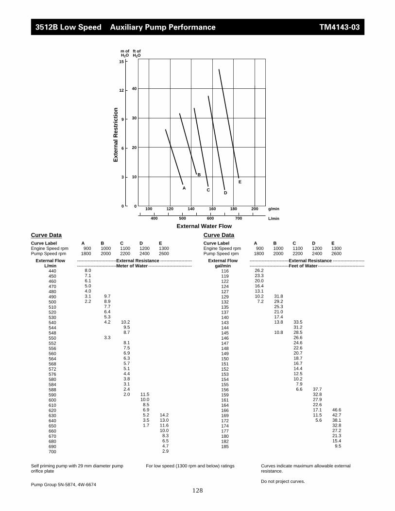
128
3512B Low Speed Auxiliary Pump Performance TM4143-03
Curve DataCurve Label A B C D EEngine Speed rpm 900 1000 1100 1200 1300Pump Speed rpm 1800 2000 2200 2400 2600
External Flow --------------------------External Resistance ---------------------L/min --------------------------Meter of Water -----------------------------
440450460470480490500510520530540544548550552556560564568572576580584588590600610620630640650660670680690700
Curve DataCurve Label A B C D EEngine Speed rpm 900 1000 1100 1200 1300Pump Speed rpm 1800 2000 2200 2400 2600
External Flow --------------------------External Resistance ---------------------gal/min --------------------------Feet of Water -------------------------------
116119122124127129132135137140143144145146147148149150151152153154155156159161164166169172174177180182185
Self priming pump with 29 mm diameter pumporifice plate
Pump Group 5N-5874, 4W-6674
For low speed (1300 rpm and below) ratings Curves indicate maximum allowable externalresistance.
Do not project curves.
8.07.16.15.04.03.12.2
9.78.97.76.45.34.2
3.3
10.29.58.7
8.17.56.96.35.75.14.43.83.12.42.0 11.5
10.08.56.95.23.51.7
14.213.011.610.0
8.36.54.72.9
26.223.320.016.413.110.2
7.231.829.225.321.017.413.8
10.8
33.531.228.526.624.622.620.718.716.714.412.510.2
7.96.6 37.7
32.827.922.617.111.5
5.6
46.642.738.132.827.221.315.4
9.5
0
Ext
ern
al R
estr
icti
on
External Water Flow
g/min
L/min
ft of H2O
m of H2O
A
0
3
180 200160
600 700
100 140
500400
B
CD
120
E10
20
30
40
6
9
12
15

129
3512 High Speed Auxiliary Pump Performance TM4141-03
Curve DataCurve Label A B C DEngine Speed rpm 1200 1500 1600 1800Pump Speed rpm 1600 2000 2133 2400
External Flow --------------------------External Resistance ---------------------L/min --------------------------Meter of Water -----------------------------
375384392400408416425500508516524532540550560570580584590600610620630640650
Curve DataCurve Label A B C DEngine Speed rpm 1200 1500 1600 1800Pump Speed rpm 1600 2000 2133 2400
External Flow --------------------------External Resistance ---------------------gal/min --------------------------Feet of Water -------------------------------
99102106110112132136138139140143145148151153154156159161164166169172
Self priming pump with 29 mm diameter pumporifice plate
Pump Group 5N-5874, 4W-6674
For high speed (1301 - 1800 rpm) ratings Curves indicate maximum allowable externalresistance.
Do not project curves.
7.06.35.64.84.03.12.1
8.97.86.85.85.04.23.3
10.8
9.28.06.75.34.0
2.92.0
12.311.510.0
8.36.75.03.31.7
22.619.415.710.2
6.929.222.3
17.7
13.810.8
35.4
33.530.226.222.017.413.1
9.56.6
40.437.732.827.222.016.410.8
5.6
0
Ext
ern
al R
estr
icti
on
External Water Flow
g/min
L/min
ft of H2O
m of H2O
A
0
3
180 200160
600 700
100 140
500400
B
CD
120
10
20
30
40
6
9
12
15
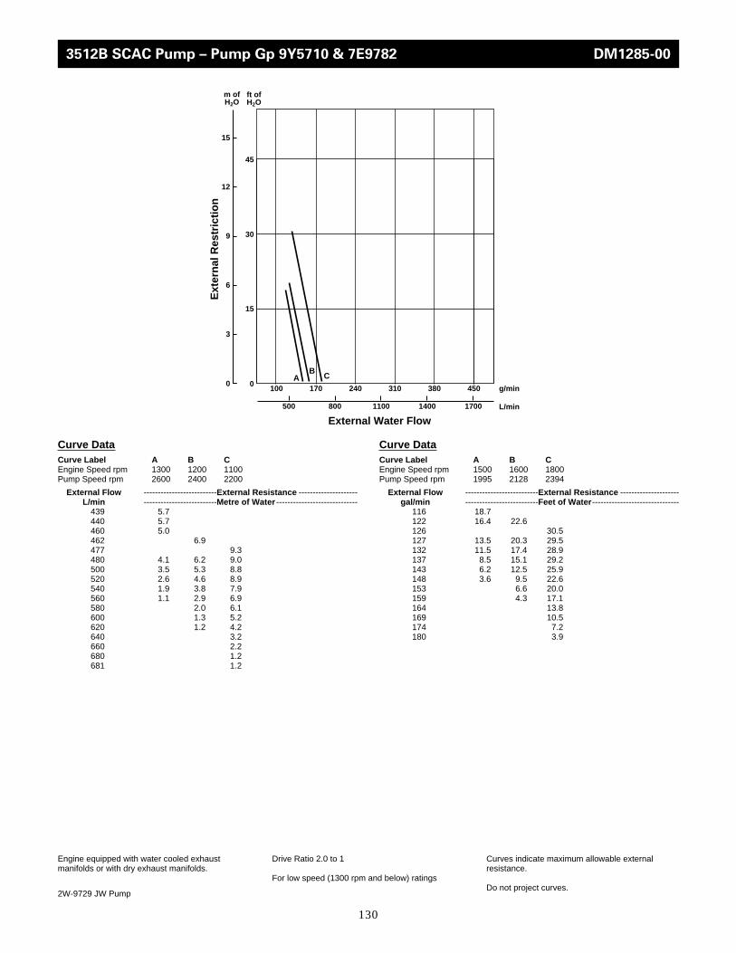
130
100 170 310 380 450
Ext
ern
al R
estr
icti
on
External Water Flow
g/min
L/min
ft of H2O
m of H2O
240A C
B
500 17001100 1400800
15
0
30
45
0
3
6
9
12
15
Curve DataCurve Label A B CEngine Speed rpm 1300 1200 1100Pump Speed rpm 2600 2400 2200
External Flow --------------------------External Resistance ---------------------L/min --------------------------Metre of Water -----------------------------
439 5.7440 5.7460 5.0462 6.9477 9.3480 4.1 6.2 9.0500 3.5 5.3 8.8520 2.6 4.6 8.9540 1.9 3.8 7.9560 1.1 2.9 6.9580 2.0 6.1600 1.3 5.2620 1.2 4.2640 3.2660 2.2680 1.2681 1.2
Curve DataCurve Label A B CEngine Speed rpm 1500 1600 1800Pump Speed rpm 1995 2128 2394
External Flow --------------------------External Resistance ---------------------gal/min --------------------------Feet of Water -------------------------------
116 18.7122 16.4 22.6126 30.5127 13.5 20.3 29.5132 11.5 17.4 28.9137 8.5 15.1 29.2143 6.2 12.5 25.9148 3.6 9.5 22.6153 6.6 20.0159 4.3 17.1164 13.8169 10.5174 7.2180 3.9
Engine equipped with water cooled exhaustmanifolds or with dry exhaust manifolds.
2W-9729 JW Pump
Drive Ratio 2.0 to 1
For low speed (1300 rpm and below) ratings
Curves indicate maximum allowable externalresistance.
Do not project curves.
3512B SCAC Pump – Pump Gp 9Y5710 & 7E9782 DM1285-00

131
3508B,3516B,3512B Auxiliary Pump Performance DM1277-01
50
0
100
Ext
ern
al R
estr
icti
on
External Water Flow
g/min
L/min
ft of H2O
m of H2O
0
15
30
260
1000 1100
200 240
900800
15045
220 280 300
A B
Curve DataCurve Label A BEngine Speed rpm 1800 1925Pump Speed rpm 1471 1573
External Flow --------------------------External Resistance ---------------------L/min --------------------------Metre of Water -----------------------------
770 50.0780 48.2800 44.6820 41.1840 37.5856 50.0860 33.9 49.2880 30.4 45.2900 26.8 41.2920 23.2 37.2940 19.6 33.2960 16.1 29.2980 12.6 25.2995 10.0
1000 21.21020 17.21040 13.21056 10.0
Curve DataCurve Label A BEngine Speed rpm 1800 1925Pump Speed rpm 1471 1573
External Flow --------------------------External Resistance ---------------------gal/min --------------------------Feet of Water -------------------------------
203 164.1206 158.1211 146.3217 134.8222 123.0226 164.1227 111.2 161.4232 99.7 148.3238 87.9 135.2243 76.1 122.1248 64.3 108.9254 52.8 95.8259 41.3 82.7263 32.8264 69.6269 56.4275 43.3279 32.8
Engine equipped with water cooled exhaustmanifolds or with dry exhaust manifolds.
2W-9729 JW Pump
Drive Ratio 2.0 to 1
For low speed (1300 rpm and below) ratings
Curves indicate maximum allowable externalresistance.
Do not project curves.

132
0
2
4
6
8
10
12
0 200 400 600 800 1000
60°
49°
38°
27°
16°
5°
Hea
t T
ran
sfer
Cap
acit
y, k
W x
102
Cooling Water Flow, L/min
0
10
20
30
40
50
60
70
0 50 100 150 200 250
140°
120°
100°
81°
61°
41°
Hea
t T
ran
sfer
Cap
acit
y, B
tu/m
in x
103
Cooling Water Flow, gal/min
Water Temp °C 60 49 38 27 16 5
Cooling Water Flow Heat Transfer Capacity
L/min kW kW kW kW kW kW
Performance Parameters
JW Flow Through Shell: 1514 L/min
JW Press. Drop: 68 kPa
JW Temp to Cooler: 99 °C
Curve Limits m/seckPa
Min Flow – Tube Velocity —Min Flow – Pressure Drop 3.3
Max Flow SW – Tube Velocity —Max Flow SW – Pressure Drop 28.8
Max Flow FW – Tube Velocity —Max Flow FW – Pressure Drop —
Water Temp °F 140 120 100 81 61 41
Cooling Water Flow Heat Transfer Capacity
gal/min Btu/min Btu/min Btu/min Btu/min Btu/min Btu/min
Performance Parameters
JW Flow Through Shell: 400 gpm
JW Press. Drop: 10 psi
JW Temp to Cooler: 210° F
Curve Limits ft/secpsi
Min Flow – Tube Velocity —Min Flow – Pressure Drop 0.5
Max Flow SW – Tube Velocity —Max Flow SW – Pressure Drop 4.2
Max Flow FW – Tube Velocity —Max Flow FW – Pressure Drop —
208 243 313 382 448 518 587300 284 365 446 523 604 685400 321 412 504 591 682 774500 354 455 556 652 753 854600 379 488 596 699 808 916700 405 521 637 747 863 978800 424 545 666 781 902 1023833 431 554 677 794 917 1041
55 13819 17800 21724 25478 29459 3338379 16151 20758 25364 29743 34349 38956
106 18255 23430 28662 33610 38785 44017132 20132 25876 31620 37079 42823 48567159 21554 27753 33894 39752 45951 52093185 23032 29629 36226 42482 49079 55619211 24113 30994 37875 44415 51297 58178220 24511 31506 38501 45155 52150 59202
Heat Exchanger Data Groups 3N-8888,3N-8889,4W-4632,107-1729 DM2593-00
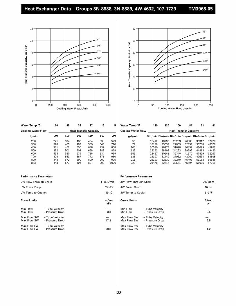
133
Water Temp °C 60 49 38 27 16 5
Cooling Water Flow Heat Transfer Capacity
L/min kW kW kW kW kW kW
Performance Parameters
JW Flow Through Shell: 1136 L/min
JW Press. Drop: 69 kPa
JW Temp to Cooler: 99 °C
Curve Limits m/seckPa
Min Flow – Tube Velocity —Min Flow – Pressure Drop 3.3
Max Flow SW – Tube Velocity —Max Flow SW – Pressure Drop 17.2
Max Flow FW – Tube Velocity —Max Flow FW – Pressure Drop 28.8
Water Temp °F 140 120 100 81 61 41
Cooling Water Flow Heat Transfer Capacity
gal/min Btu/min Btu/min Btu/min Btu/min Btu/min Btu/min
Performance Parameters
JW Flow Through Shell: 300 gpm
JW Press. Drop: 10 psi
JW Temp to Cooler: 210 °F
Curve Limits ft/secpsi
Min Flow – Tube Velocity —Min Flow – Pressure Drop 0.5
Max Flow SW – Tube Velocity —Max Flow SW – Pressure Drop 2.5
Max Flow FW – Tube Velocity —Max Flow FW – Pressure Drop 4.2
208 271 334 408 464 533 579300 320 405 489 569 646 710400 361 462 556 648 732 808500 392 501 603 698 788 869600 413 530 639 738 834 919700 429 553 667 773 871 960800 443 572 690 800 900 995833 448 577 696 807 909 1006
55 15412 18995 23203 26388 30312 3292879 18198 23032 27809 32359 36738 40378
106 20530 26274 31620 36852 41629 45951132 22293 28492 34293 39695 44813 49420159 23487 30141 36340 41970 47429 52263185 24397 31449 37932 43960 49534 54595211 25193 32530 39240 45496 51183 56586220 25478 32814 39581 45894 51695 57211
0
2
4
6
8
10
12
0 200 400 600 800 1000
60°
49°
38°
27°
16°
5°
Hea
t T
ran
sfer
Cap
acit
y, k
W x
102
Cooling Water Flow, L/min
0
10
20
30
40
50
60
0 50 100 150 200 250
140°
120°
100°
81°
61°
41°
Hea
t T
ran
sfer
Cap
acit
y, B
tu/m
in x
103
Cooling Water Flow, gal/min
Heat Exchanger Data Groups 3N-8888, 3N-8889, 4W-4632, 107-1729 TM3968-05
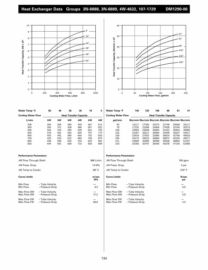
134
Water Temp °C 60 49 38 30 16 5
Cooling Water Flow Heat Transfer Capacity
L/min kW kW kW kW kW kW
Performance Parameters
JW Flow Through Shell: 568 L/min
JW Press. Drop: 14 kPa
JW Temp to Cooler: 99° C
Curve Limits m/seckPa
Min Flow – Tube Velocity —Min Flow – Pressure Drop 3.3
Max Flow SW – Tube Velocity —Max Flow SW – Pressure Drop 17.2
Max Flow FW – Tube Velocity —Max Flow FW – Pressure Drop 28.8
Water Temp °F 140 120 100 86 61 41
Cooling Water Flow Heat Transfer Capacity
gal/min Btu/min Btu/min Btu/min Btu/min Btu/min Btu/min
Performance Parameters
JW Flow Through Shell: 150 gpm
JW Press. Drop: 2 psi
JW Temp to Cooler: 210° F
Curve Limits ft/secpsi
Min Flow – Tube Velocity —Min Flow – Pressure Drop 0.5
Max Flow SW – Tube Velocity —Max Flow SW – Pressure Drop 2.5
Max Flow FW – Tube Velocity —Max Flow FW – Pressure Drop 4.2
208 250 305 360 400 467 512300 303 371 438 486 567 622400 344 419 494 549 641 703500 378 461 545 605 707 774600 403 491 580 644 752 825700 425 519 612 680 794 870800 438 538 633 704 823 902833 444 541 639 710 829 909
55 14217 17345 20473 22748 26558 2911779 17232 21099 24909 27639 32245 35373
106 19563 23828 28094 31222 36454 39980132 21497 26217 30994 34406 40207 44017159 22919 27923 32985 36624 42766 46918185 24170 29515 34804 38672 45155 49477211 24909 30596 35999 40036 46804 51297220 25250 30767 36340 40378 47145 51695
0
1
2
3
4
5
6
7
8
9
10
0 200 400 600 800 1000
60°
49°
38°
30°
16°
5°
Hea
t T
ran
sfer
Cap
acit
y, k
W x
102
Cooling Water Flow, L/min
0
10
20
30
40
50
60
0 50 100 150 200 250
140°
120°
100°
86°
61°
41°
Hea
t T
ran
sfer
Cap
acit
y, B
tu/m
in x
103
Cooling Water Flow, gal/min
Heat Exchanger Data Groups 3N-8888, 3N-8889, 4W-4632, 107-1729 DM1290-00

135
Heat Exchanger Data Groups 3N-8888, 3N-8889, 4W-4632, 107-1729 DM1291-00
Water Temp °C 60 49 38 30 16 5
Cooling Water Flow Heat Transfer Capacity
L/min kW kW kW kW kW kW
Performance Parameters
JW Flow Through Shell: 568 L/min
JW Press. Drop: 14 kPa
JW Temp to Cooler: 65° C
Curve Limits m/seckPa
Min Flow – Tube Velocity — Min Flow – Pressure Drop 3.3
Max Flow SW – Tube Velocity -------—Max Flow SW – Pressure Drop -------17.2
Max Flow FW– Tube Velocity —Max Flow FW– Pressure Drop 28.8
Water Temp °F 140 120 100 86 61 41
Cooling Water Flow Heat Transfer Capacity
gal/min Btu/min Btu/min Btu/min Btu/min Btu/min Btu/min
Performance Parameters
JW Flow Through Shell: 150 gpm
JW Press. Drop: 2 psi
JW Temp to Cooler: 149° F
Curve Limits ft/secpsi
Min Flow – Tube Velocity —Min Flow – Pressure Drop 0.5
Max Flow SW – Tube Velocity -------—Max Flow SW – Pressure Drop -------2.5
Max Flow FW– Tube Velocity —Max Flow FW– Pressure Drop 4.2
208 30 89 148 190 257 300300 38 110 183 235 319 372400 43 126 211 270 366 427500 47 138 230 295 400 466600 51 150 245 315 426 496700 53 154 257 330 447 521800 55 161 269 345 467 545833 56 164 273 350 474 553
55 1706 5061 8417 10805 14616 1706179 2161 6256 10407 13364 18141 21156
106 2445 7166 12000 15355 20814 24283132 2673 7848 13080 16777 22748 26501159 2900 8530 13933 17914 24227 28207185 3014 8758 14616 18767 25421 29629211 3128 9156 15298 19620 26558 30994220 3185 9327 15525 19904 26956 31449
0
1
2
3
4
5
6
0 200 400 600 800 1000
60°
49°
38°
30°
16°
5°
Hea
t T
ran
sfer
Cap
acit
y, k
W x
102
Cooling Water Flow, L/min
0
5
10
15
20
25
30
35
0 50 100 150 200 250
140°
120°
100°
86°
61°
41°
Hea
t T
ran
sfer
Cap
acit
y, B
tu/m
in x
103
Cooling Water Flow, gal/min

136
Heat Exchanger Data Groups 3N-8888, 3N-8889, 4W-4632, 107-1729 TM1300-00
Water Temp °C 60 49 38 30 16 5
Cooling Water Flow Heat Transfer Capacity
L/min kW kW kW kW kW kW
Performance Parameters
JW Flow Through Shell: 568 L/min
JW Press. Drop: 14 kPa
JW Temp to Cooler: 41° C
Curve Limits m/seckPa
Min Flow – Tube Velocity —Min Flow – Pressure Drop 3.3
Max Flow SW – Tube Velocity —Max Flow SW – Pressure Drop 17.2
Max Flow FW – Tube Velocity —Max Flow FW – Pressure Drop 28.8
Water Temp °F 140 120 100 86 61 41
Cooling Water Flow Heat Transfer Capacity
gal/min Btu/min Btu/min Btu/min Btu/min Btu/min Btu/min
Performance Parameters
JW Flow Through Shell: 150 gpm
JW Press. Drop: 2 psi
JW Temp to Cooler: 106° F
Curve Limits ft/secpsi
Min Flow – Tube Velocity —Min Flow – Pressure Drop 0.5
Max Flow SW – Tube Velocity —Max Flow SW – Pressure Drop 2.5
Max Flow FW – Tube Velocity —Max Flow FW – Pressure Drop 4.2
208 – – 19 62 139 201300 – – 22 72 162 233400 – – 24 80 180 260500 – – 26 87 195 282600 – – 28 93 209 301700 – – 29 97 218 314800 – – 30 100 226 326833 – – 30 101 228 330
55 – – 1081 3526 7905 1143179 – – 1251 4095 9213 13251
106 – – 1365 4550 10237 14786132 – – 1479 4948 11090 16037159 – – 1592 5289 11886 17118185 – – 1649 5516 12398 17857211 – – 1706 5687 12853 18540220 – – 1706 5744 12966 18767
0
1
2
3
4
0 200 400 600 800 1000
38°
30°
16°
5°
Hea
t T
ran
sfer
Cap
acit
y, k
W x
102
Cooling Water Flow, L/min
0
2
4
6
8
10
12
14
16
18
20
0 50 100 150 200 250
100°
86°
61°
41°
Hea
t T
ran
sfer
Cap
acit
y, B
tu/m
in x
103
Cooling Water Flow, gal/min

137
Heat Exchanger Data Groups 3N-8890, 3N-8891, 4W-4642, 107-1728 DM2594-00
Water Temp °C 60 49 38 27 16 5
Cooling Water Flow Heat Transfer Capacity
L/min kW kW kW kW kW kW
Performance Parameters
JW Flow Through Shell: 1514 L/min
JW Press. Drop: 57 kPa
JW Temp to Cooler: 99° C
Curve Limits m/seckPa
Min Flow – Tube Velocity —Min Flow – Pressure Drop 2.1
Max Flow SW – Tube Velocity -------—Max Flow SW – Pressure Drop -------2.3
Max Flow FW– Tube Velocity —Max Flow FW– Pressure Drop 4.0
Water Temp °F 140 120 100 81 61 41
Cooling Water Flow Heat Transfer Capacity
gal/min Btu/min Btu/min Btu/min Btu/min Btu/min Btu/min
Performance Parameters
JW Flow Through Shell: 400 gpm
JW Press. Drop: 8 psi
JW Temp to Cooler: 210° F
Curve Limits ft/secpsi
Min Flow – Tube Velocity —Min Flow – Pressure Drop 0.3
Max Flow SW – Tube Velocity -------—Max Flow SW – Pressure Drop -------2.3
Max Flow FW– Tube Velocity —Max Flow FW– Pressure Drop 4.0
208 287 369 452 530 612 694300 346 445 544 638 737 836400 398 512 625 733 847 961500 435 559 683 801 925 1050600 472 606 741 869 1004 1138700 501 644 787 923 1066 1210800 523 673 822 964 1113 1263833 531 682 834 978 1129 1281
55 16322 20985 25705 30141 34804 3946879 19677 25307 30937 36283 41913 47543
106 22634 29117 35544 41686 48169 54652132 24738 31790 38842 45553 52605 59713159 26843 34463 42141 49420 57097 64718185 28492 36624 44757 52491 60623 68813211 29743 38273 46747 54823 63296 71827220 30198 38785 47429 55619 64206 72850
0
2
4
6
8
10
12
14
0 200 400 600 800 1000
60°
49°
38°
27°
16°
5°
Hea
t T
ran
sfer
Cap
acit
y, k
W x
102
Cooling Water Flow, L/min
0
10
20
30
40
50
60
70
80
0 50 100 150 200 250
140°
120°
100°
81°
61°
41°
Hea
t T
ran
sfer
Cap
acit
y, B
tu/m
in x
103
Cooling Water Flow, gal/min

138
Heat Exchanger Data Groups 3N-8890, 3N-8891, 4W-4642, 107-728 TM3969-05
Water Temp °C 60 50 38 27 16 4
Cooling Water Flow Heat Transfer Capacity
L/min kW kW kW kW kW kW
Performance Parameters
JW Flow Through Shell: 1136 L/min
JW Press. Drop: 34 kPa
JW Temp to Cooler: 98° C
Curve Limits m/seckPa
Min Flow – Tube Velocity —Min Flow – Pressure Drop 2.1
Max Flow SW – Tube Velocity —Max Flow SW – Pressure Drop 15.9
Max Flow FW – Tube Velocity —Max Flow FW – Pressure Drop 27.6
Water Temp °F 140 122 100 81 61 39
Cooling Water Flow Heat Transfer Capacity
gal/min Btu/min Btu/min Btu/min Btu/min Btu/min Btu/min
Performance Parameters
JW Flow Through Shell: 300 gpm
JW Press. Drop: 5 psi
JW Temp to Cooler: 208° F
Curve Limits ft/secpsi
Min Flow – Tube Velocity —Min Flow – Pressure Drop .3
Max Flow SW – Tube Velocity —Max Flow SW – Pressure Drop 2.3
Max Flow FW – Tube Velocity —Max Flow FW – Pressure Drop 4.0
208 325 401 484 552 644 717300 386 486 593 683 786 851400 438 557 677 785 895 961500 477 607 731 851 965 1041600 506 647 775 903 1023 1113700 533 681 810 945 1073 1175800 556 708 839 984 1116 1229833 563 716 848 997 1129 1245
55 18483 22805 27525 31392 36624 4077679 21952 27639 33724 38842 44700 48396
106 24909 31677 38501 44643 50899 54652132 27127 34520 41572 48396 54879 59202159 28776 36795 44074 51354 58178 63296185 30312 38728 46065 53742 61021 66822211 31620 40264 47714 55960 63467 69893220 32018 40719 48226 56699 64206 70803
0
2
4
6
8
10
12
14
0 200 400 600 800 1000
60°
50°
38°
27°
16°
4°
Hea
t T
ran
sfer
Cap
acit
y, k
W x
102
Cooling Water Flow, L/min
0
10
20
30
40
50
60
70
80
0 50 100 150 200 250
140°
122°
100°
81°
61°
39°
Hea
t T
ran
sfer
Cap
acit
y, B
tu/m
in x
103
Cooling Water Flow, gal/min
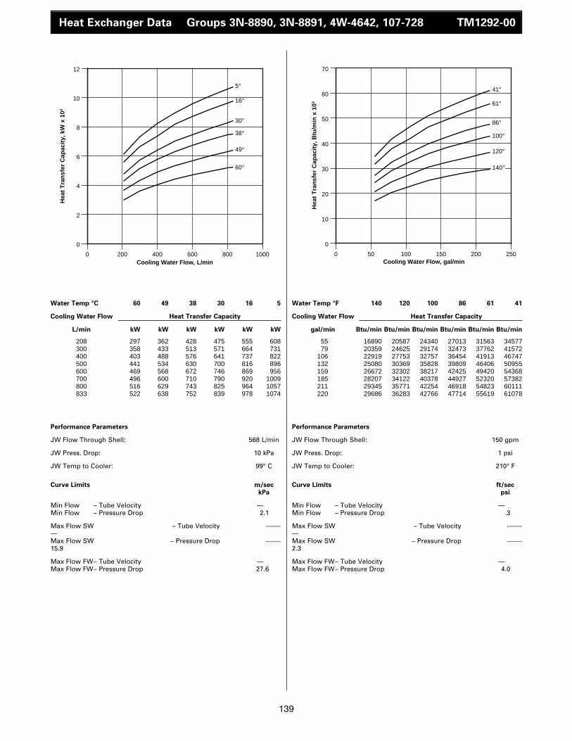
139
Heat Exchanger Data Groups 3N-8890, 3N-8891, 4W-4642, 107-728 TM1292-00
Water Temp °C 60 49 38 30 16 5
Cooling Water Flow Heat Transfer Capacity
L/min kW kW kW kW kW kW
Performance Parameters
JW Flow Through Shell: 568 L/min
JW Press. Drop: 10 kPa
JW Temp to Cooler: 99° C
Curve Limits m/seckPa
Min Flow – Tube Velocity —Min Flow – Pressure Drop 2.1
Max Flow SW – Tube Velocity -------—Max Flow SW – Pressure Drop -------15.9
Max Flow FW– Tube Velocity —Max Flow FW– Pressure Drop 27.6
Water Temp °F 140 120 100 86 61 41
Cooling Water Flow Heat Transfer Capacity
gal/min Btu/min Btu/min Btu/min Btu/min Btu/min Btu/min
Performance Parameters
JW Flow Through Shell: 150 gpm
JW Press. Drop: 1 psi
JW Temp to Cooler: 210° F
Curve Limits ft/secpsi
Min Flow – Tube Velocity —Min Flow – Pressure Drop .3
Max Flow SW – Tube Velocity -------—Max Flow SW – Pressure Drop -------2.3
Max Flow FW– Tube Velocity —Max Flow FW– Pressure Drop 4.0
208 297 362 428 475 555 608300 358 433 513 571 664 731400 403 488 576 641 737 822500 441 534 630 700 816 896600 469 568 672 746 869 956700 496 600 710 790 920 1009800 516 629 743 825 964 1057833 522 638 752 839 978 1074
55 16890 20587 24340 27013 31563 3457779 20359 24625 29174 32473 37762 41572
106 22919 27753 32757 36454 41913 46747132 25080 30369 35828 39809 46406 50955159 26672 32302 38217 42425 49420 54368185 28207 34122 40378 44927 52320 57382211 29345 35771 42254 46918 54823 60111220 29686 36283 42766 47714 55619 61078
0
2
4
6
8
10
12
0 200 400 600 800 1000
60°
49°
38°
30°
16°
5°
Hea
t T
ran
sfer
Cap
acit
y, k
W x
102
Cooling Water Flow, L/min
0
10
20
30
40
50
60
70
0 50 100 150 200 250
140°
120°
100°
86°
61°
41°
Hea
t T
ran
sfer
Cap
acit
y, B
tu/m
in x
103
Cooling Water Flow, gal/min

140
Heat Exchanger Data Groups 3N-8890, 3N8891, 4W-4642, 107-1728 DM1293-00
Water Temp °C 60 49 38 30 16 5
Cooling Water Flow Heat Transfer Capacity
L/min kW kW kW kW kW kW
Performance Parameters
JW Flow Through Shell: 568 L/min
JW Press. Drop: 10 kPa
JW Temp to Cooler: 65° C
Curve Limits m/seckPa
Min Flow – Tube Velocity —Min Flow – Pressure Drop 2.1
Max Flow SW – Tube Velocity —Max Flow SW – Pressure Drop 15.9
Max Flow FW – Tube Velocity —Max Flow FW – Pressure Drop 27.6
Water Temp °F 140 120 100 86 61 41
Cooling Water Flow Heat Transfer Capacity
gal/min Btu/min Btu/min Btu/min Btu/min Btu/min Btu/min
Performance Parameters
JW Flow Through Shell: 150 gpm
JW Press. Drop: 1 psi
JW Temp to Cooler: 149° F
Curve Limits ft/secpsi
Min Flow – Tube Velocity —Min Flow – Pressure Drop .3
Max Flow SW – Tube Velocity —Max Flow SW – Pressure Drop 2.3
Max Flow FW – Tube Velocity —Max Flow FW – Pressure Drop 4.0
208 35 103 172 220 298 348300 45 131 218 280 380 443400 50 152 251 322 434 507500 55 168 275 353 473 552600 61 178 292 376 502 587700 63 184 307 393 528 616800 65 190 316 405 549 640833 66 192 320 410 555 648
55 1990 5858 9782 12511 16947 1979179 2559 7450 12398 15924 21611 25193
106 2843 8644 14274 18312 24682 28833132 3128 9554 15639 20075 26899 31392159 3469 10123 16606 21383 28549 33383185 3583 10464 17459 22350 30027 35032211 3697 10805 17971 23032 31222 36397220 3753 10919 18198 23317 31563 36852
0
1
2
3
4
5
6
7
0 200 400 600 800 1000
60°
49°
38°
30°
16°
5°
Hea
t T
ran
sfer
Cap
acit
y, k
W x
102
Cooling Water Flow, L/min
0
5
10
15
20
25
30
35
40
0 50 100 150 200 250
140°
120°
100°
86°
61°
41°
Hea
t T
ran
sfer
Cap
acit
y, B
tu/m
in x
103
Cooling Water Flow, gal/min

141
Heat Exchanger Data Groups 3N-8890, 3N-8891, 4W4642, 107-1728 DM2576-00
Water Temp °C 60 49 38 30 16 5
Cooling Water Flow Heat Transfer Capacity
L/min kW kW kW kW kW kW
Performance Parameters
JW Flow Through Shell: 568 L/min
JW Press. Drop: 10 kPa
JW Temp to Cooler: 41° C
Curve Limits m/seckPa
Min Flow – Tube Velocity —Min Flow – Pressure Drop 2.1
Max Flow SW – Tube Velocity -------—Max Flow SW – Pressure Drop -------16.0
Max Flow FW– Tube Velocity —Max Flow FW– Pressure Drop —
Water Temp °F 140 120 100 86 61 41
Cooling Water Flow Heat Transfer Capacity
gal/min Btu/min Btu/min Btu/min Btu/min Btu/min Btu/min
Performance Parameters
JW Flow Through Shell: 150 gpm
JW Press. Drop: 1 psi
JW Temp to Cooler: 106° F
Curve Limits ft/secpsi
Min Flow – Tube Velocity —Min Flow – Pressure Drop 0.3
Max Flow SW – Tube Velocity -------—Max Flow SW – Pressure Drop -------2.3
Max Flow FW– Tube Velocity —Max Flow FW– Pressure Drop —
208 – – 22 73 165 239300 – – 26 86 194 280400 – – 29 97 218 314500 – – 31 105 235 340600 – – 33 111 250 362700 – – 35 116 262 378800 – – 36 120 271 391833 – – 37 122 274 395
55 – – 1251 4152 9384 1359279 – – 1479 4891 11033 15924
106 – – 1649 5516 12398 17857132 – – 1763 5971 13364 19336159 – – 1877 6313 14217 20587185 – – 1990 6597 14900 21497211 – – 2047 6824 15412 22236220 – – 2104 6938 15582 22464
0
1
2
3
4
5
0 200 400 600 800 1000
38°
30°
16°
5°
Hea
t T
ran
sfer
Cap
acit
y, k
W x
102
Cooling Water Flow, L/min
0
5
10
15
20
25
0 50 100 150 200 250
100°
86°
61°
41°
Hea
t T
ran
sfer
Cap
acit
y, B
tu/m
in x
103
Cooling Water Flow, gal/min

142
Heat Exchanger Data Groups 3N-8892, 3N-8893, 4W4652, 107-1730 TM3833-06
Water Temp °C 60 50 38 27 16 4
Cooling Water Flow Heat Transfer Capacity
L/min kW kW kW kW kW kW
Performance Parameters
JW Flow Through Shell: 1514 L/min
JW Press. Drop: 91 kPa
JW Temp to Cooler: 98° C
Curve Limits m/seckPa
Min Flow – Tube Velocity —Min Flow – Pressure Drop 2.1
Max Flow SW – Tube Velocity —Max Flow SW – Pressure Drop 19.3
Max Flow FW – Tube Velocity —Max Flow FW – Pressure Drop 34.4
Water Temp °F 136 122 100 81 61 39
Cooling Water Flow Heat Transfer Capacity
gal/min Btu/min Btu/min Btu/min Btu/min Btu/min Btu/min
Performance Parameters
JW Flow Through Shell: 400 gpm
JW Press. Drop: 13 psi
JW Temp to Cooler: 208° F
Curve Limits ft/secpsi
Min Flow – Tube Velocity —Min Flow – Pressure Drop 0.3
Max Flow SW – Tube Velocity —Max Flow SW – Pressure Drop 2.8
Max Flow FW – Tube Velocity —Max Flow FW – Pressure Drop 5.0
208 360 459 550 668 754 853300 449 580 697 812 911 1018400 524 671 809 927 1038 1164500 577 730 881 1009 1129 1280600 615 777 940 1078 1208 1383700 650 817 991 1139 1280 1479800 678 852 1037 1196 1347 1569833 686 863 1050 1213 1368 1597
55 20473 26103 31278 37989 42880 4851079 25535 32985 39638 46178 51808 57894
106 29800 38160 46008 52718 59031 66197132 32814 41515 50102 57382 64206 72793159 34975 44188 53458 61306 68699 78651185 36965 46463 56358 64775 72793 84111211 38558 48453 58974 68016 76604 89229220 39013 49079 59713 68983 77798 90821
0
2
4
6
8
10
12
14
16
18
0 200 400 600 800 1000
60°
50°
38°
27°
16°
4°
Hea
t T
ran
sfer
Cap
acit
y, k
W x
102
Cooling Water Flow, L/min
0
10
20
30
40
50
60
70
80
90
100
0 50 100 150 200 250
136°
122°
100°
81°
61°
39°
Hea
t T
ran
sfer
Cap
acit
y, B
tu/m
in x
103
Cooling Water Flow, gal/min
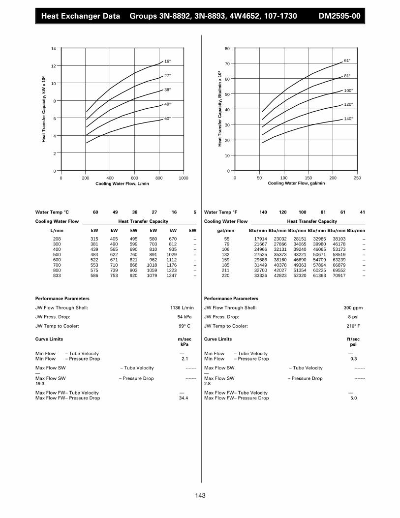
143
Heat Exchanger Data Groups 3N-8892, 3N-8893, 4W4652, 107-1730 DM2595-00
Water Temp °C 60 49 38 27 16 5
Cooling Water Flow Heat Transfer Capacity
L/min kW kW kW kW kW kW
Performance Parameters
JW Flow Through Shell: 1136 L/min
JW Press. Drop: 54 kPa
JW Temp to Cooler: 99° C
Curve Limits m/seckPa
Min Flow – Tube Velocity —Min Flow – Pressure Drop 2.1
Max Flow SW – Tube Velocity -------—Max Flow SW – Pressure Drop -------19.3
Max Flow FW– Tube Velocity —Max Flow FW– Pressure Drop 34.4
Water Temp °F 140 120 100 81 61 41
Cooling Water Flow Heat Transfer Capacity
gal/min Btu/min Btu/min Btu/min Btu/min Btu/min Btu/min
Performance Parameters
JW Flow Through Shell: 300 gpm
JW Press. Drop: 8 psi
JW Temp to Cooler: 210° F
Curve Limits ft/secpsi
Min Flow – Tube Velocity —Min Flow – Pressure Drop 0.3
Max Flow SW – Tube Velocity -------—Max Flow SW – Pressure Drop -------2.8
Max Flow FW– Tube Velocity —Max Flow FW– Pressure Drop 5.0
208 315 405 495 580 670 –300 381 490 599 703 812 –400 439 565 690 810 935 –500 484 622 760 891 1029 –600 522 671 821 962 1112 –700 553 710 868 1018 1176 –800 575 739 903 1059 1223 –833 586 753 920 1079 1247 –
55 17914 23032 28151 32985 38103 –79 21667 27866 34065 39980 46178 –
106 24966 32131 39240 46065 53173 –132 27525 35373 43221 50671 58519 –159 29686 38160 46690 54709 63239 –185 31449 40378 49363 57894 66879 –211 32700 42027 51354 60225 69552 –220 33326 42823 52320 61363 70917 –
0
2
4
6
8
10
12
14
0 200 400 600 800 1000
60°
49°
38°
27°
16°
Hea
t T
ran
sfer
Cap
acit
y, k
W x
102
Cooling Water Flow, L/min
0
10
20
30
40
50
60
70
80
0 50 100 150 200 250
140°
120°
100°
81°
61°
Hea
t T
ran
sfer
Cap
acit
y, B
tu/m
in x
103
Cooling Water Flow, gal/min

144
Heat Exchanger Data Groups 3N-8892, 3N-8893, 4W-4652, 107-1730 DM1294-00
Water Temp °C 60 49 38 30 16 5
Cooling Water Flow Heat Transfer Capacity
L/min kW kW kW kW kW kW
Performance Parameters
JW Flow Through Shell: 568 L/min
JW Press. Drop: 15 kPa
JW Temp to Cooler: 99° C
Curve Limits m/seckPa
Min Flow – Tube Velocity —Min Flow – Pressure Drop 2.1
Max Flow SW – Tube Velocity —Max Flow SW – Pressure Drop 19.3
Max Flow FW – Tube Velocity —Max Flow FW – Pressure Drop 34.4
Water Temp °F 140 120 100 86 61 41
Cooling Water Flow Heat Transfer Capacity
gal/min Btu/min Btu/min Btu/min Btu/min Btu/min Btu/min
Performance Parameters
JW Flow Through Shell: 150 gpm
JW Press. Drop: 2 psi
JW Temp to Cooler: 210° F
Curve Limits ft/secpsi
Min Flow – Tube Velocity —Min Flow – Pressure Drop 0.3
Max Flow SW – Tube Velocity —Max Flow SW – Pressure Drop 2.8
Max Flow FW – Tube Velocity —Max Flow FW – Pressure Drop 5.0
208 338 412 486 540 631 691300 401 489 577 641 749 820400 459 559 659 729 855 939500 500 612 720 800 934 1024600 537 654 771 856 1000 1097700 567 692 815 906 1058 1160800 594 724 855 950 1110 1217833 600 731 867 964 1125 1235
55 19222 23430 27639 30710 35885 3929779 22805 27809 32814 36454 42596 46633
106 26103 31790 37477 41458 48624 53401132 28435 34804 40946 45496 53116 58235159 30539 37193 43847 48681 56870 62386185 32245 39354 46349 51524 60168 65969211 33781 41174 48624 54026 63126 69211220 34122 41572 49306 54823 63979 70234
0
2
4
6
8
10
12
14
0 200 400 600 800 1000
60°
49°
38°
30°
16°
5°
Hea
t T
ran
sfer
Cap
acit
y, k
W x
102
Cooling Water Flow, L/min
0
10
20
30
40
50
60
70
80
0 50 100 150 200 250
140°
120°
100°
86°
61°
41°
Hea
t T
ran
sfer
Cap
acit
y, B
tu/m
in x
103
Cooling Water Flow, gal/min
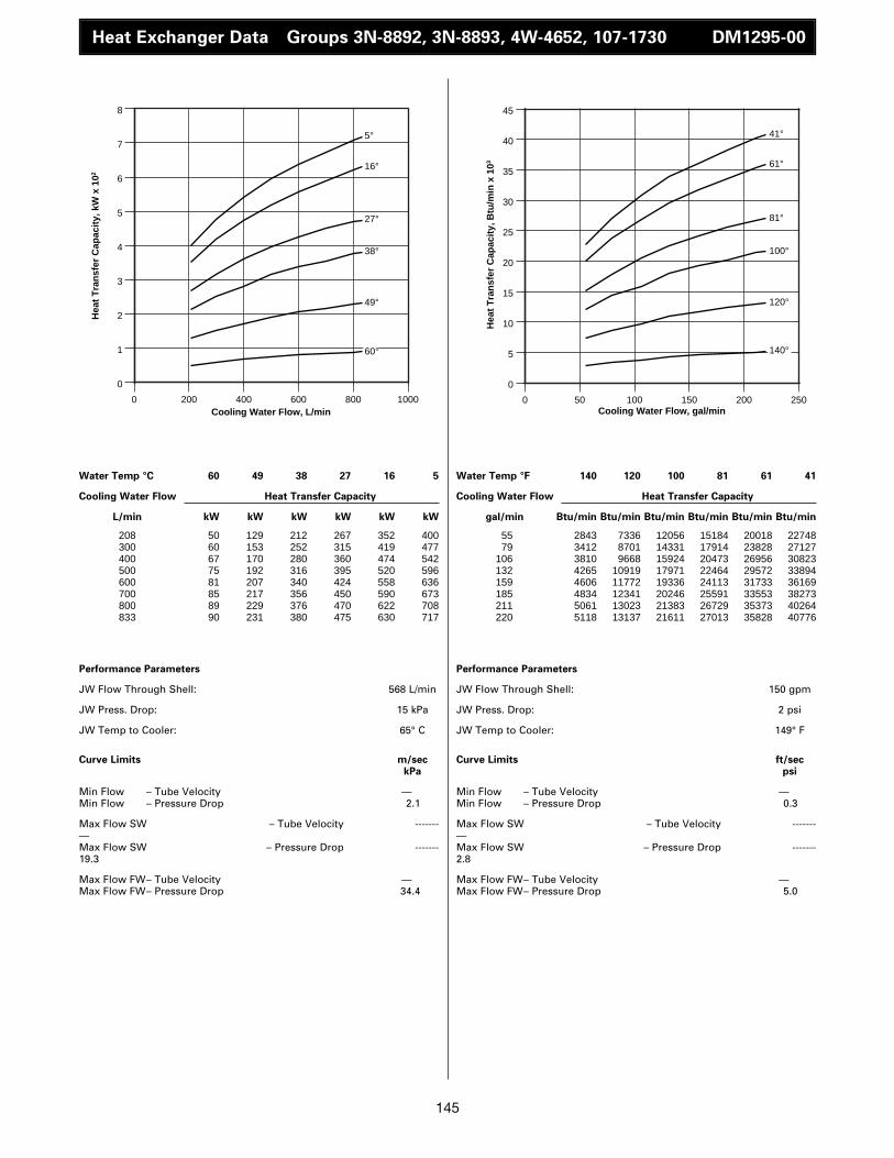
145
Heat Exchanger Data Groups 3N-8892, 3N-8893, 4W-4652, 107-1730 DM1295-00
Water Temp °C 60 49 38 27 16 5
Cooling Water Flow Heat Transfer Capacity
L/min kW kW kW kW kW kW
Performance Parameters
JW Flow Through Shell: 568 L/min
JW Press. Drop: 15 kPa
JW Temp to Cooler: 65° C
Curve Limits m/seckPa
Min Flow – Tube Velocity —Min Flow – Pressure Drop 2.1
Max Flow SW – Tube Velocity -------—Max Flow SW – Pressure Drop -------19.3
Max Flow FW– Tube Velocity —Max Flow FW– Pressure Drop 34.4
Water Temp °F 140 120 100 81 61 41
Cooling Water Flow Heat Transfer Capacity
gal/min Btu/min Btu/min Btu/min Btu/min Btu/min Btu/min
Performance Parameters
JW Flow Through Shell: 150 gpm
JW Press. Drop: 2 psi
JW Temp to Cooler: 149° F
Curve Limits ft/secpsi
Min Flow – Tube Velocity —Min Flow – Pressure Drop 0.3
Max Flow SW – Tube Velocity -------—Max Flow SW – Pressure Drop -------2.8
Max Flow FW– Tube Velocity —Max Flow FW– Pressure Drop 5.0
208 50 129 212 267 352 400300 60 153 252 315 419 477400 67 170 280 360 474 542500 75 192 316 395 520 596600 81 207 340 424 558 636700 85 217 356 450 590 673800 89 229 376 470 622 708833 90 231 380 475 630 717
55 2843 7336 12056 15184 20018 2274879 3412 8701 14331 17914 23828 27127
106 3810 9668 15924 20473 26956 30823132 4265 10919 17971 22464 29572 33894159 4606 11772 19336 24113 31733 36169185 4834 12341 20246 25591 33553 38273211 5061 13023 21383 26729 35373 40264220 5118 13137 21611 27013 35828 40776
0
1
2
3
4
5
6
7
8
0 200 400 600 800 1000
60°
49°
38°
27°
16°
5°
Hea
t T
ran
sfer
Cap
acit
y, k
W x
102
Cooling Water Flow, L/min
0
5
10
15
20
25
30
35
40
45
0 50 100 150 200 250
140°
120°
100°
81°
61°
41°
Hea
t T
ran
sfer
Cap
acit
y, B
tu/m
in x
103
Cooling Water Flow, gal/min

146
Heat Exchanger Data Groups 3N-8892, 3N-8893, 4W-4652, 107-1730 DM2577-00
Water Temp °C 60 49 38 30 16 5
Cooling Water Flow Heat Transfer Capacity
L/min kW kW kW kW kW kW
Performance Parameters
JW Flow Through Shell: 568 L/min
JW Press. Drop: 15 kPa
JW Temp to Cooler: 41° C
Curve Limits m/seckPa
Min Flow – Tube Velocity —Min Flow – Pressure Drop 2.1
Max Flow SW – Tube Velocity —Max Flow SW – Pressure Drop 19.3
Max Flow FW – Tube Velocity —Max Flow FW – Pressure Drop 34.4
Water Temp °F 140 120 100 86 61 41
Cooling Water Flow Heat Transfer Capacity
gal/min Btu/min Btu/min Btu/min Btu/min Btu/min Btu/min
Performance Parameters
JW Flow Through Shell: 150 gpm
JW Press. Drop: 2 psi
JW Temp to Cooler: 106° F
Curve Limits ft/secpsi
Min Flow – Tube Velocity —Min Flow – Pressure Drop 0.3
Max Flow SW – Tube Velocity —Max Flow SW – Pressure Drop 2.8
Max Flow FW – Tube Velocity —Max Flow FW – Pressure Drop 5.0
208 – – 24 81 181 262300 – – 29 96 215 310400 – – 32 108 242 350500 – – 35 117 264 381600 – – 37 124 280 404700 – – 39 130 293 423800 – – 41 135 304 439833 – – 41 137 307 444
55 – – 1365 4606 10293 1490079 – – 1649 5460 12227 17630
106 – – 1820 6142 13763 19904132 – – 1990 6654 15014 21667159 – – 2104 7052 15924 22975185 – – 2218 7393 16663 24056211 – – 2332 7677 17288 24966220 – – 2332 7791 17459 25250
0
1
2
3
4
5
0 200 400 600 800 1000
38°
30°
16°
5°
Hea
t T
ran
sfer
Cap
acit
y, k
W x
102
Cooling Water Flow, L/min
0
5
10
15
20
25
30
0 50 100 150 200 250
100°
86°
61°
41°
Hea
t T
ran
sfer
Cap
acit
y, B
tu/m
in x
103
Cooling Water Flow, gal/min

147
3516B Jacket Water System Performance DM1299-00
15
0
30
45
250 300 400 450 500
Ext
ern
al R
estr
icti
on
External Water Flow
g/min
L/min
ft of H2O
m of H2O
350
A
C
0
3
6
9
12
15
1000 180016001200
B
1400
Curve DataCurve Label A B CEngine Speed rpm 1800 1600 1100Pump Speed rpm 2400 2133 2200
External Flow --------------------------External Resistance ---------------------L/min --------------------------Meter of Water -----------------------------18021800170016011600150014991480144014001360132013001280124012001160112011001080106710401000
999
Curve DataCurve Label A B CEngine Speed rpm 1300 1200 1500Pump Speed rpm 2600 2400 2000
External Flow --------------------------External Resistance ---------------------gal/min --------------------------Feet of Water -------------------------------
264275282285291296306317328338343349359370380391396423449476
Engine equipped with water cooled exhaustmanifolds or with dry exhaust manifolds.Engine mounted expansion tank.
2W-9729 JW Pump
Drive Ratio 1.33 to 1
6.86.88.4
9.811.4
12.9
14.3
16.1
5.75.77.0
8.4
9.7
11.1
12.4
12.8
5.15.45.86.36.87.2
7.68.28.69.09.4
10.0
10.711.211.2
52.8
46.9
42.3
37.432.227.622.3
42.0
40.7
36.4
31.8
27.6
23.018.7
36.735.1
32.8
30.829.528.226.924.9
23.622.320.719.017.716.7

148
3516B Low Speed Auxiliary Pump Performance TM4143-03
Curve DataCurve Label A B C D EEngine Speed rpm 900 1000 1100 1200 1300Pump Speed rpm 1800 2000 2200 2400 2600
External Flow --------------------------External Resistance ---------------------L/min --------------------------Meter of Water -----------------------------
440450460470480490500510520530540544548550552556560564568572576580584588590600610620630640650660670680690700
Curve DataCurve Label A B C D EEngine Speed rpm 900 1000 1100 1200 1300Pump Speed rpm 1800 2000 2200 2400 2600
External Flow --------------------------External Resistance ---------------------gal/min --------------------------Feet of Water -------------------------------
116119122124127129132135137140143144145146147148149150151152153154155156159161164166169172174177180182185
Self priming pump with 29 mm diameter pumporifice plate
Pump Group 5N-5874, 4W-6674
For low speed (1300 rpm and below) ratings Curves indicate maximum allowable externalresistance.
Do not project curves.
8.07.16.15.04.03.12.2
9.78.97.76.45.34.2
3.3
10.29.58.7
8.17.56.96.35.75.14.43.83.12.42.0 11.5
10.08.56.95.23.51.7
14.213.011.610.0
8.36.54.72.9
26.223.320.016.413.110.2
7.231.829.225.321.017.413.8
10.8
33.531.228.526.624.622.620.718.716.714.412.510.2
7.96.6 37.7
32.827.922.617.111.5
5.6
46.642.738.132.827.221.315.4
9.5
0
Ext
ern
al R
estr
icti
on
External Water Flow
g/min
L/min
ft of H2O
m of H2O
A
0
3
180 200160
600 700
100 140
500400
B
CD
120
E10
20
30
40
6
9
12
15

149
3516 High Speed Auxiliary Pump Performance TM4141-03
Curve DataCurve Label A B C DEngine Speed rpm 1200 1500 1600 1800Pump Speed rpm 1600 2000 2133 2400
External Flow --------------------------External Resistance ---------------------L/min --------------------------Meter of Water -----------------------------
375384392400408416425500508516524532540550560570580584590600610620630640650
Curve DataCurve Label A B C DEngine Speed rpm 1200 1500 1600 1800Pump Speed rpm 1600 2000 2133 2400
External Flow --------------------------External Resistance ---------------------gal/min --------------------------Feet of Water -------------------------------
99102106110112132136138139140143145148151153154156159161164166169172
Self priming pump with 29 mm diameter pumporifice plate
Pump Group 5N-5874, 4W-6674
For high speed (1301 - 1800 rpm) ratings Curves indicate maximum allowable externalresistance.
Do not project curves.
7.06.35.64.84.03.12.1
8.97.86.85.85.04.23.3
10.8
9.28.06.75.34.0
2.92.0
12.311.510.0
8.36.75.03.31.7
22.619.415.710.2
6.929.222.3
17.7
13.810.8
35.4
33.530.226.222.017.413.1
9.56.6
40.437.732.827.222.016.410.8
5.6
0
Ext
ern
al R
estr
icti
on
External Water Flow
g/min
L/min
ft of H2O
m of H2O
A
0
3
180 200160
600 700
100 140
500400
B
CD
120
10
20
30
40
6
9
12
15
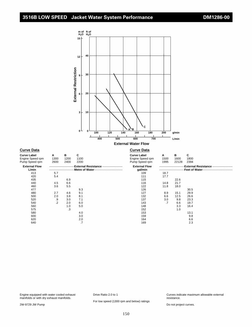
150
0
Ext
ern
al R
estr
icti
on
External Water Flow
g/min
L/min
ft of H2O
m of H2O
A0
3
180 200160
600 700
100 140
500400
BC
120
10
20
30
40
6
9
12
15
Curve DataCurve Label A B CEngine Speed rpm 1300 1200 1100Pump Speed rpm 2600 2400 2200
External Flow --------------------------External Resistance ---------------------L/min --------------------------Metre of Water -----------------------------
413 5.7420 5.4435 6.9440 4.5 6.6460 3.6 5.5477 9.3480 2.7 4.6 9.1500 2.0 3.8 8.1520 .9 3.0 7.1540 .2 2.0 6.0560 1.0 5.0575 .3580 4.0600 3.0620 2.0640 .7
Curve DataCurve Label A B CEngine Speed rpm 1500 1600 1800Pump Speed rpm 1995 22128 2394
External Flow --------------------------External Resistance ---------------------gal/min --------------------------Feet of Water -------------------------------
109 18.7111 17.7115 22.6116 14.8 21.7122 11.8 18.0126 30.5127 8.9 15.1 29.9132 6.6 12.5 26.6137 3.0 9.8 23.3143 .7 6.6 19.7148 3.3 16.4152 1.0153 13.1159 9.8164 6.6169 2.3
Engine equipped with water cooled exhaustmanifolds or with dry exhaust manifolds.
2W-9729 JW Pump
Drive Ratio 2.0 to 1
For low speed (1300 rpm and below) ratings
Curves indicate maximum allowable externalresistance.
Do not project curves.
3516B LOW SPEED Jacket Water System Performance DM1286-00

151
3508B,3516B,3512B Auxiliary Pump Performance DM1277-01
50
0
100
Ext
ern
al R
estr
icti
on
External Water Flow
g/min
L/min
ft of H2O
m of H2O
0
15
30
260
1000 1100
200 240
900800
15045
220 280 300
A B
Curve DataCurve Label A BEngine Speed rpm 1800 1925Pump Speed rpm 1471 1573
External Flow --------------------------External Resistance ---------------------L/min --------------------------Metre of Water -----------------------------
770 50.0780 48.2800 44.6820 41.1840 37.5856 50.0860 33.9 49.2880 30.4 45.2900 26.8 41.2920 23.2 37.2940 19.6 33.2960 16.1 29.2980 12.6 25.2995 10.0
1000 21.21020 17.21040 13.21056 10.0
Curve DataCurve Label A BEngine Speed rpm 1800 1925Pump Speed rpm 1471 1573
External Flow --------------------------External Resistance ---------------------gal/min --------------------------Feet of Water -------------------------------
203 164.1206 158.1211 146.3217 134.8222 123.0226 164.1227 111.2 161.4232 99.7 148.3238 87.9 135.2243 76.1 122.1248 64.3 108.9254 52.8 95.8259 41.3 82.7263 32.8264 69.6269 56.4275 43.3279 32.8
Engine equipped with water cooled exhaustmanifolds or with dry exhaust manifolds.
2W-9729 JW Pump
Drive Ratio 2.0 to 1
For low speed (1300 rpm and below) ratings
Curves indicate maximum allowable externalresistance.
Do not project curves.

152
Heat Exchanger Data Groups 3N8890, 3N8891, 4W4642 TM3969-04
Water Temp °C 60 49 38 27 16 5
Cooling Water Flow Heat Transfer Capacity
L/min kW kW kW kW kW kW
Performance Parameters
JW Flow Through Shell: 1514 L/min
JW Press. Drop: 68 kPa
JW Temp to Cooler: 99° C
Curve Limits m/seckPa
Min Flow – Tube Velocity —Min Flow – Pressure Drop 3.3
Max Flow SW– Tube Velocity —Max Flow SW– Pressure Drop 28.8
Max Flow FW– Tube Velocity —Max Flow FW– Pressure Drop —
Water Temp °F 140 120 100 81 61 41
Cooling Water Flow Heat Transfer Capacity
gal/min Btu/min Btu/min Btu/min Btu/min Btu/min Btu/min
Performance Parameters
JW Flow Through Shell: 400 gpm
JW Press. Drop: 10 psi
JW Temp to Cooler: 210° F
Curve Limits ft/secpsi
Min Flow – Tube Velocity —Min Flow – Pressure Drop 0.5
Max Flow SW– Tube Velocity —Max Flow SW– Pressure Drop 4.2
Max Flow FW– Tube Velocity —Max Flow FW– Pressure Drop —
208 243 313 382 448 518 587300 284 365 446 523 604 685400 321 412 504 591 682 774500 354 455 556 652 753 854600 379 488 596 699 808 916700 405 521 637 747 863 978800 424 545 666 781 902 1023833 431 554 677 794 917 1041
55 13819 17800 21724 25478 29459 3338379 16151 20758 25364 29743 34349 38956
106 18255 23430 28662 33610 38785 44017132 20132 25876 31620 37079 42823 48567159 21554 27753 33894 39752 45951 52093185 23032 29629 36226 42482 49079 55619211 24113 30994 37875 44415 51297 58178220 24511 31506 38501 45155 52150 59202
0
2
4
6
8
10
12
0 200 400 600 800 1000
60°
49°
38°
27°
16°
5°
Hea
t T
ran
sfer
Cap
acit
y, k
W x
102
Cooling Water Flow, L/min
0
10
20
30
40
50
60
70
0 50 100 150 200 250
140°
120°
100°
81°
61°
41°
Hea
t T
ran
sfer
Cap
acit
y, B
tu/m
in x
103
Cooling Water Flow, gal/min
Heat Exchanger Data Groups 3N-8888,3N-8889,4W-4632,107-1729 DM2593-00
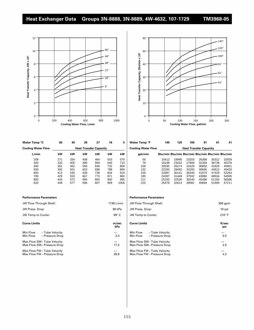
153
Water Temp °C 60 49 38 27 16 5
Cooling Water Flow Heat Transfer Capacity
L/min kW kW kW kW kW kW
Performance Parameters
JW Flow Through Shell: 1136 L/min
JW Press. Drop: 69 kPa
JW Temp to Cooler: 99° C
Curve Limits m/seckPa
Min Flow – Tube Velocity —Min Flow – Pressure Drop 3.3
Max Flow SW– Tube Velocity —Max Flow SW– Pressure Drop 17.2
Max Flow FW– Tube Velocity —Max Flow FW– Pressure Drop 28.8
Water Temp °F 140 120 100 81 61 41
Cooling Water Flow Heat Transfer Capacity
gal/min Btu/min Btu/min Btu/min Btu/min Btu/min Btu/min
Performance Parameters
JW Flow Through Shell: 300 gpm
JW Press. Drop: 10 psi
JW Temp to Cooler: 210° F
Curve Limits ft/secpsi
Min Flow – Tube Velocity —Min Flow – Pressure Drop 0.5
Max Flow SW– Tube Velocity —Max Flow SW– Pressure Drop 2.5
Max Flow FW– Tube Velocity —Max Flow FW– Pressure Drop 4.2
208 271 334 408 464 533 579300 320 405 489 569 646 710400 361 462 556 648 732 808500 392 501 603 698 788 869600 413 530 639 738 834 919700 429 553 667 773 871 960800 443 572 690 800 900 995833 448 577 696 807 909 1006
55 15412 18995 23203 26388 30312 3292879 18198 23032 27809 32359 36738 40378
106 20530 26274 31620 36852 41629 45951132 22293 28492 34293 39695 44813 49420159 23487 30141 36340 41970 47429 52263185 24397 31449 37932 43960 49534 54595211 25193 32530 39240 45496 51183 56586220 25478 32814 39581 45894 51695 57211
0
2
4
6
8
10
12
0 200 400 600 800 1000
60°
49°
38°
27°
16°
5°
Hea
t T
ran
sfer
Cap
acit
y, k
W x
102
Cooling Water Flow, L/min
0
10
20
30
40
50
60
0 50 100 150 200 250
140°
120°
100°
81°
61°
41°
Hea
t T
ran
sfer
Cap
acit
y, B
tu/m
in x
103
Cooling Water Flow, gal/min
Heat Exchanger Data Groups 3N-8888, 3N-8889, 4W-4632, 107-1729 TM3968-05

154
Water Temp °C 60 49 38 30 16 5
Cooling Water Flow Heat Transfer Capacity
L/min kW kW kW kW kW kW
Performance Parameters
JW Flow Through Shell: 568 L/min
JW Press. Drop: 14 kPa
JW Temp to Cooler: 99° C
Curve Limits m/seckPa
Min Flow – Tube Velocity —Min Flow – Pressure Drop 3.3
Max Flow SW– Tube Velocity —Max Flow SW– Pressure Drop 17.2
Max Flow FW– Tube Velocity —Max Flow FW– Pressure Drop 28.8
Water Temp °F 140 120 100 86 61 41
Cooling Water Flow Heat Transfer Capacity
gal/min Btu/min Btu/min Btu/min Btu/min Btu/min Btu/min
Performance Parameters
JW Flow Through Shell: 150 gpm
JW Press. Drop: 2 psi
JW Temp to Cooler: 210° F
Curve Limits ft/secpsi
Min Flow – Tube Velocity —Min Flow – Pressure Drop 0.5
Max Flow SW– Tube Velocity —Max Flow SW– Pressure Drop 2.5
Max Flow FW– Tube Velocity —Max Flow FW– Pressure Drop 4.2
208 250 305 360 400 467 512300 303 371 438 486 567 622400 344 419 494 549 641 703500 378 461 545 605 707 774600 403 491 580 644 752 825700 425 519 612 680 794 870800 438 538 633 704 823 902833 444 541 639 710 829 909
55 14217 17345 20473 22748 26558 2911779 17232 21099 24909 27639 32245 35373
106 19563 23828 28094 31222 36454 39980132 21497 26217 30994 34406 40207 44017159 22919 27923 32985 36624 42766 46918185 24170 29515 34804 38672 45155 49477211 24909 30596 35999 40036 46804 51297220 25250 30767 36340 40378 47145 51695
0
1
2
3
4
5
6
7
8
9
10
0 200 400 600 800 1000
60°
49°
38°
30°
16°
5°
Hea
t T
ran
sfer
Cap
acit
y, k
W x
102
Cooling Water Flow, L/min
0
10
20
30
40
50
60
0 50 100 150 200 250
140°
120°
100°
86°
61°
41°
Hea
t T
ran
sfer
Cap
acit
y, B
tu/m
in x
103
Cooling Water Flow, gal/min
Heat Exchanger Data Groups 3N-8888, 3N-8889, 4W-4632, 107-1729 DM1290-00

155
Heat Exchanger Data Groups 3N-8888, 3N-8889, 4W-4632, 107-1729 DM1291-00
Water Temp °C 60 49 38 30 16 5
Cooling Water Flow Heat Transfer Capacity
L/min kW kW kW kW kW kW
Performance Parameters
JW Flow Through Shell: 568 L/min
JW Press. Drop: 14 kPa
JW Temp to Cooler: 65° C
Curve Limits m/seckPa
Min Flow – Tube Velocity — Min Flow – Pressure Drop 3.3
Max Flow SW– Tube Velocity —Max Flow SW– Pressure Drop 17.2
Max Flow FW– Tube Velocity —Max Flow FW– Pressure Drop 28.8
Water Temp °F 140 120 100 86 61 41
Cooling Water Flow Heat Transfer Capacity
gal/min Btu/min Btu/min Btu/min Btu/min Btu/min Btu/min
Performance Parameters
JW Flow Through Shell: 150 gpm
JW Press. Drop: 2 psi
JW Temp to Cooler: 149° F
Curve Limits ft/secpsi
Min Flow – Tube Velocity —Min Flow – Pressure Drop 0.5
Max Flow SW– Tube Velocity —Max Flow SW– Pressure Drop 2.5
Max Flow FW– Tube Velocity —Max Flow FW– Pressure Drop 4.2
208 30 89 148 190 257 300300 38 110 183 235 319 372400 43 126 211 270 366 427500 47 138 230 295 400 466600 51 150 245 315 426 496700 53 154 257 330 447 521800 55 161 269 345 467 545833 56 164 273 350 474 553
55 1706 5061 8417 10805 14616 1706179 2161 6256 10407 13364 18141 21156
106 2445 7166 12000 15355 20814 24283132 2673 7848 13080 16777 22748 26501159 2900 8530 13933 17914 24227 28207185 3014 8758 14616 18767 25421 29629211 3128 9156 15298 19620 26558 30994220 3185 9327 15525 19904 26956 31449
0
1
2
3
4
5
6
0 200 400 600 800 1000
60°
49°
38°
30°
16°
5°
Hea
t T
ran
sfer
Cap
acit
y, k
W x
102
Cooling Water Flow, L/min
0
5
10
15
20
25
30
35
0 50 100 150 200 250
140°
120°
100°
86°
61°
41°
Hea
t T
ran
sfer
Cap
acit
y, B
tu/m
in x
103
Cooling Water Flow, gal/min

156
Heat Exchanger Data Groups 3N-8888, 3N-8889, 4W-4632, 107-1729 TM1300-00
Water Temp °C 60 49 38 30 16 5
Cooling Water Flow Heat Transfer Capacity
L/min kW kW kW kW kW kW
Performance Parameters
JW Flow Through Shell: 568 L/min
JW Press. Drop: 14 kPa
JW Temp to Cooler: 41° C
Curve Limits m/seckPa
Min Flow – Tube Velocity —Min Flow – Pressure Drop 3.3
Max Flow SW– Tube Velocity —Max Flow SW– Pressure Drop 17.2
Max Flow FW– Tube Velocity —Max Flow FW– Pressure Drop 28.8
Water Temp °F 140 120 100 86 61 41
Cooling Water Flow Heat Transfer Capacity
gal/min Btu/min Btu/min Btu/min Btu/min Btu/min Btu/min
Performance Parameters
JW Flow Through Shell: 150 gpm
JW Press. Drop: 2 psi
JW Temp to Cooler: 106° F
Curve Limits ft/secpsi
Min Flow – Tube Velocity —Min Flow – Pressure Drop 0.5
Max Flow SW– Tube Velocity —Max Flow SW– Pressure Drop 2.5
Max Flow FW– Tube Velocity —Max Flow FW– Pressure Drop 4.2
208 – – 19 62 139 201300 – – 22 72 162 233400 – – 24 80 180 260500 – – 26 87 195 282600 – – 28 93 209 301700 – – 29 97 218 314800 – – 30 100 226 326833 – – 30 101 228 330
55 – – 1081 3526 7905 1143179 – – 1251 4095 9213 13251
106 – – 1365 4550 10237 14786132 – – 1479 4948 11090 16037159 – – 1592 5289 11886 17118185 – – 1649 5516 12398 17857211 – – 1706 5687 12853 18540220 – – 1706 5744 12966 18767
0
1
2
3
4
0 200 400 600 800 1000
38°
30°
16°
5°
Hea
t T
ran
sfer
Cap
acit
y, k
W x
102
Cooling Water Flow, L/min
0
2
4
6
8
10
12
14
16
18
20
0 50 100 150 200 250
100°
86°
61°
41°
Hea
t T
ran
sfer
Cap
acit
y, B
tu/m
in x
103
Cooling Water Flow, gal/min
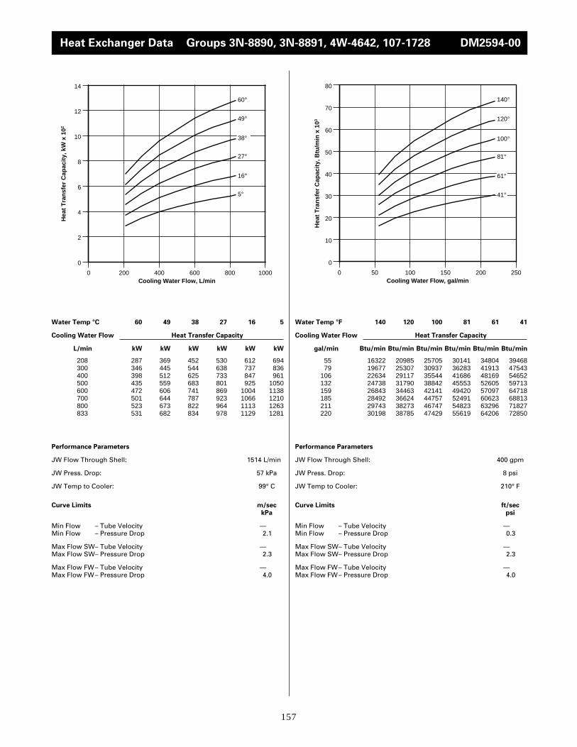
157
Heat Exchanger Data Groups 3N-8890, 3N-8891, 4W-4642, 107-1728 DM2594-00
Water Temp °C 60 49 38 27 16 5
Cooling Water Flow Heat Transfer Capacity
L/min kW kW kW kW kW kW
Performance Parameters
JW Flow Through Shell: 1514 L/min
JW Press. Drop: 57 kPa
JW Temp to Cooler: 99° C
Curve Limits m/seckPa
Min Flow – Tube Velocity —Min Flow – Pressure Drop 2.1
Max Flow SW– Tube Velocity —Max Flow SW– Pressure Drop 2.3
Max Flow FW– Tube Velocity —Max Flow FW– Pressure Drop 4.0
Water Temp °F 140 120 100 81 61 41
Cooling Water Flow Heat Transfer Capacity
gal/min Btu/min Btu/min Btu/min Btu/min Btu/min Btu/min
Performance Parameters
JW Flow Through Shell: 400 gpm
JW Press. Drop: 8 psi
JW Temp to Cooler: 210° F
Curve Limits ft/secpsi
Min Flow – Tube Velocity —Min Flow – Pressure Drop 0.3
Max Flow SW– Tube Velocity —Max Flow SW– Pressure Drop 2.3
Max Flow FW– Tube Velocity —Max Flow FW– Pressure Drop 4.0
208 287 369 452 530 612 694300 346 445 544 638 737 836400 398 512 625 733 847 961500 435 559 683 801 925 1050600 472 606 741 869 1004 1138700 501 644 787 923 1066 1210800 523 673 822 964 1113 1263833 531 682 834 978 1129 1281
55 16322 20985 25705 30141 34804 3946879 19677 25307 30937 36283 41913 47543
106 22634 29117 35544 41686 48169 54652132 24738 31790 38842 45553 52605 59713159 26843 34463 42141 49420 57097 64718185 28492 36624 44757 52491 60623 68813211 29743 38273 46747 54823 63296 71827220 30198 38785 47429 55619 64206 72850
0
2
4
6
8
10
12
14
0 200 400 600 800 1000
60°
49°
38°
27°
16°
5°
Hea
t T
ran
sfer
Cap
acit
y, k
W x
102
Cooling Water Flow, L/min
0
10
20
30
40
50
60
70
80
0 50 100 150 200 250
140°
120°
100°
81°
61°
41°
Hea
t T
ran
sfer
Cap
acit
y, B
tu/m
in x
103
Cooling Water Flow, gal/min

158
Heat Exchanger Data Groups 3N-8890, 3N-8891, 4W-4642, 107-728 TM3969-05
Water Temp °C 60 50 38 27 16 4
Cooling Water Flow Heat Transfer Capacity
L/min kW kW kW kW kW kW
Performance Parameters
JW Flow Through Shell: 1136 L/min
JW Press. Drop: 34 kPa
JW Temp to Cooler: 98° C
Curve Limits m/seckPa
Min Flow – Tube Velocity —Min Flow – Pressure Drop 2.1
Max Flow SW– Tube Velocity —Max Flow SW– Pressure Drop 15.9
Max Flow FW– Tube Velocity —Max Flow FW– Pressure Drop 27.6
Water Temp °F 140 122 100 81 61 39
Cooling Water Flow Heat Transfer Capacity
gal/min Btu/min Btu/min Btu/min Btu/min Btu/min Btu/min
Performance Parameters
JW Flow Through Shell: 300 gpm
JW Press. Drop: 5 psi
JW Temp to Cooler: 208° F
Curve Limits ft/secpsi
Min Flow – Tube Velocity —Min Flow – Pressure Drop .3
Max Flow SW– Tube Velocity —Max Flow SW– Pressure Drop 2.3
Max Flow FW– Tube Velocity —Max Flow FW– Pressure Drop 4.0
208 325 401 484 552 644 717300 386 486 593 683 786 851400 438 557 677 785 895 961500 477 607 731 851 965 1041600 506 647 775 903 1023 1113700 533 681 810 945 1073 1175800 556 708 839 984 1116 1229833 563 716 848 997 1129 1245
55 18483 22805 27525 31392 36624 4077679 21952 27639 33724 38842 44700 48396
106 24909 31677 38501 44643 50899 54652132 27127 34520 41572 48396 54879 59202159 28776 36795 44074 51354 58178 63296185 30312 38728 46065 53742 61021 66822211 31620 40264 47714 55960 63467 69893220 32018 40719 48226 56699 64206 70803
0
2
4
6
8
10
12
14
0 200 400 600 800 1000
60°
50°
38°
27°
16°
4°
Hea
t T
ran
sfer
Cap
acit
y, k
W x
102
Cooling Water Flow, L/min
0
10
20
30
40
50
60
70
80
0 50 100 150 200 250
140°
122°
100°
81°
61°
39°
Hea
t T
ran
sfer
Cap
acit
y, B
tu/m
in x
103
Cooling Water Flow, gal/min

159
Heat Exchanger Data Groups 3N-8890, 3N-8891, 4W-4642, 107-728 TM1292-00
Water Temp °C 60 49 38 30 16 5
Cooling Water Flow Heat Transfer Capacity
L/min kW kW kW kW kW kW
Performance Parameters
JW Flow Through Shell: 568 L/min
JW Press. Drop: 10 kPa
JW Temp to Cooler: 99° C
Curve Limits m/seckPa
Min Flow – Tube Velocity —Min Flow – Pressure Drop 2.1
Max Flow SW– Tube Velocity —Max Flow SW– Pressure Drop 15.9
Max Flow FW– Tube Velocity —Max Flow FW– Pressure Drop 27.6
Water Temp °F 140 120 100 86 61 41
Cooling Water Flow Heat Transfer Capacity
gal/min Btu/min Btu/min Btu/min Btu/min Btu/min Btu/min
Performance Parameters
JW Flow Through Shell: 150 gpm
JW Press. Drop: 1 psi
JW Temp to Cooler: 210° F
Curve Limits ft/secpsi
Min Flow – Tube Velocity —Min Flow – Pressure Drop .3
Max Flow SW– Tube Velocity —Max Flow SW– Pressure Drop 2.3
Max Flow FW– Tube Velocity —Max Flow FW– Pressure Drop 4.0
208 297 362 428 475 555 608300 358 433 513 571 664 731400 403 488 576 641 737 822500 441 534 630 700 816 896600 469 568 672 746 869 956700 496 600 710 790 920 1009800 516 629 743 825 964 1057833 522 638 752 839 978 1074
55 16890 20587 24340 27013 31563 3457779 20359 24625 29174 32473 37762 41572
106 22919 27753 32757 36454 41913 46747132 25080 30369 35828 39809 46406 50955159 26672 32302 38217 42425 49420 54368185 28207 34122 40378 44927 52320 57382211 29345 35771 42254 46918 54823 60111220 29686 36283 42766 47714 55619 61078
0
2
4
6
8
10
12
0 200 400 600 800 1000
60°
49°
38°
30°
16°
5°
Hea
t T
ran
sfer
Cap
acit
y, k
W x
102
Cooling Water Flow, L/min
0
10
20
30
40
50
60
70
0 50 100 150 200 250
140°
120°
100°
86°
61°
41°
Hea
t T
ran
sfer
Cap
acit
y, B
tu/m
in x
103
Cooling Water Flow, gal/min

160
Heat Exchanger Data Groups 3N-8890, 3N8891, 4W-4642, 107-1728 DM1293-00
Water Temp °C 60 49 38 30 16 5
Cooling Water Flow Heat Transfer Capacity
L/min kW kW kW kW kW kW
Performance Parameters
JW Flow Through Shell: 568 L/min
JW Press. Drop: 10 kPa
JW Temp to Cooler: 65° C
Curve Limits m/seckPa
Min Flow – Tube Velocity —Min Flow – Pressure Drop 2.1
Max Flow SW– Tube Velocity —Max Flow SW– Pressure Drop 15.9
Max Flow FW– Tube Velocity —Max Flow FW– Pressure Drop 27.6
Water Temp °F 140 120 100 86 61 41
Cooling Water Flow Heat Transfer Capacity
gal/min Btu/min Btu/min Btu/min Btu/min Btu/min Btu/min
Performance Parameters
JW Flow Through Shell: 150 gpm
JW Press. Drop: 1 psi
JW Temp to Cooler: 149° F
Curve Limits ft/secpsi
Min Flow – Tube Velocity —Min Flow – Pressure Drop .3
Max Flow SW– Tube Velocity —Max Flow SW– Pressure Drop 2.3
Max Flow FW– Tube Velocity —Max Flow FW– Pressure Drop 4.0
208 35 103 172 220 298 348300 45 131 218 280 380 443400 50 152 251 322 434 507500 55 168 275 353 473 552600 61 178 292 376 502 587700 63 184 307 393 528 616800 65 190 316 405 549 640833 66 192 320 410 555 648
55 1990 5858 9782 12511 16947 1979179 2559 7450 12398 15924 21611 25193
106 2843 8644 14274 18312 24682 28833132 3128 9554 15639 20075 26899 31392159 3469 10123 16606 21383 28549 33383185 3583 10464 17459 22350 30027 35032211 3697 10805 17971 23032 31222 36397220 3753 10919 18198 23317 31563 36852
0
1
2
3
4
5
6
7
0 200 400 600 800 1000
60°
49°
38°
30°
16°
5°
Hea
t T
ran
sfer
Cap
acit
y, k
W x
102
Cooling Water Flow, L/min
0
5
10
15
20
25
30
35
40
0 50 100 150 200 250
140°
120°
100°
86°
61°
41°
Hea
t T
ran
sfer
Cap
acit
y, B
tu/m
in x
103
Cooling Water Flow, gal/min
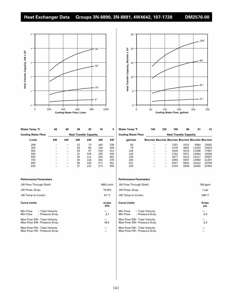
161
Heat Exchanger Data Groups 3N-8890, 3N-8891, 4W4642, 107-1728 DM2576-00
Water Temp °C 60 49 38 30 16 5
Cooling Water Flow Heat Transfer Capacity
L/min kW kW kW kW kW kW
Performance Parameters
JW Flow Through Shell: 568 L/min
JW Press. Drop: 10 kPa
JW Temp to Cooler: 41° C
Curve Limits m/seckPa
Min Flow – Tube Velocity —Min Flow – Pressure Drop 2.1
Max Flow SW– Tube Velocity —Max Flow SW– Pressure Drop 16.0
Max Flow FW– Tube Velocity —Max Flow FW– Pressure Drop —
Water Temp °F 140 120 100 86 61 41
Cooling Water Flow Heat Transfer Capacity
gal/min Btu/min Btu/min Btu/min Btu/min Btu/min Btu/min
Performance Parameters
JW Flow Through Shell: 150 gpm
JW Press. Drop: 1 psi
JW Temp to Cooler: 106° F
Curve Limits ft/secpsi
Min Flow – Tube Velocity —Min Flow – Pressure Drop 0.3
Max Flow SW– Tube Velocity —Max Flow SW– Pressure Drop 2.3
Max Flow FW– Tube Velocity —Max Flow FW– Pressure Drop —
208 – – 22 73 165 239300 – – 26 86 194 280400 – – 29 97 218 314500 – – 31 105 235 340600 – – 33 111 250 362700 – – 35 116 262 378800 – – 36 120 271 391833 – – 37 122 274 395
55 – – 1251 4152 9384 1359279 – – 1479 4891 11033 15924
106 – – 1649 5516 12398 17857132 – – 1763 5971 13364 19336159 – – 1877 6313 14217 20587185 – – 1990 6597 14900 21497211 – – 2047 6824 15412 22236220 – – 2104 6938 15582 22464
0
1
2
3
4
5
0 200 400 600 800 1000
38°
30°
16°
5°
Hea
t T
ran
sfer
Cap
acit
y, k
W x
102
Cooling Water Flow, L/min
0
5
10
15
20
25
0 50 100 150 200 250
100°
86°
61°
41°
Hea
t T
ran
sfer
Cap
acit
y, B
tu/m
in x
103
Cooling Water Flow, gal/min

162
Heat Exchanger Data Groups 3N-8892, 3N-8893, 4W4652, 107-1730 TM3833-06
Water Temp °C 60 50 38 27 16 4
Cooling Water Flow Heat Transfer Capacity
L/min kW kW kW kW kW kW
Performance Parameters
JW Flow Through Shell: 1514 L/min
JW Press. Drop: 91 kPa
JW Temp to Cooler: 98° C
Curve Limits m/seckPa
Min Flow – Tube Velocity —Min Flow – Pressure Drop 2.1
Max Flow SW– Tube Velocity —Max Flow SW– Pressure Drop 19.3
Max Flow FW– Tube Velocity —Max Flow FW– Pressure Drop 34.4
Water Temp °F 136 122 100 81 61 39
Cooling Water Flow Heat Transfer Capacity
gal/min Btu/min Btu/min Btu/min Btu/min Btu/min Btu/min
Performance Parameters
JW Flow Through Shell: 400 gpm
JW Press. Drop: 13 psi
JW Temp to Cooler: 208° F
Curve Limits ft/secpsi
Min Flow – Tube Velocity —Min Flow – Pressure Drop 0.3
Max Flow SW– Tube Velocity —Max Flow SW– Pressure Drop 2.8
Max Flow FW– Tube Velocity —Max Flow FW– Pressure Drop 5.0
208 360 459 550 668 754 853300 449 580 697 812 911 1018400 524 671 809 927 1038 1164500 577 730 881 1009 1129 1280600 615 777 940 1078 1208 1383700 650 817 991 1139 1280 1479800 678 852 1037 1196 1347 1569833 686 863 1050 1213 1368 1597
55 20473 26103 31278 37989 42880 4851079 25535 32985 39638 46178 51808 57894
106 29800 38160 46008 52718 59031 66197132 32814 41515 50102 57382 64206 72793159 34975 44188 53458 61306 68699 78651185 36965 46463 56358 64775 72793 84111211 38558 48453 58974 68016 76604 89229220 39013 49079 59713 68983 77798 90821
0
2
4
6
8
10
12
14
16
18
0 200 400 600 800 1000
60°
50°
38°
27°
16°
4°
Hea
t T
ran
sfer
Cap
acit
y, k
W x
102
Cooling Water Flow, L/min
0
10
20
30
40
50
60
70
80
90
100
0 50 100 150 200 250
136°
122°
100°
81°
61°
39°
Hea
t T
ran
sfer
Cap
acit
y, B
tu/m
in x
103
Cooling Water Flow, gal/min
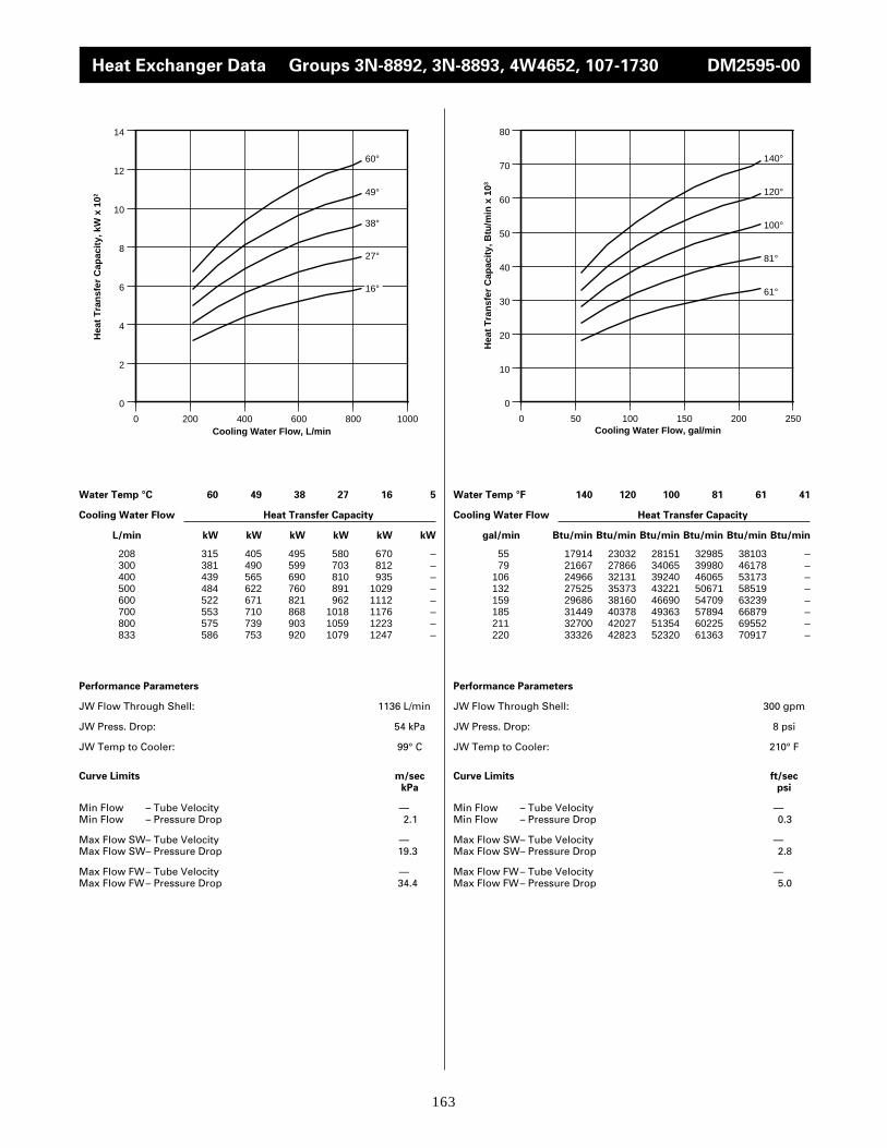
163
Heat Exchanger Data Groups 3N-8892, 3N-8893, 4W4652, 107-1730 DM2595-00
Water Temp °C 60 49 38 27 16 5
Cooling Water Flow Heat Transfer Capacity
L/min kW kW kW kW kW kW
Performance Parameters
JW Flow Through Shell: 1136 L/min
JW Press. Drop: 54 kPa
JW Temp to Cooler: 99° C
Curve Limits m/seckPa
Min Flow – Tube Velocity —Min Flow – Pressure Drop 2.1
Max Flow SW– Tube Velocity —Max Flow SW– Pressure Drop 19.3
Max Flow FW– Tube Velocity —Max Flow FW– Pressure Drop 34.4
Water Temp °F 140 120 100 81 61 41
Cooling Water Flow Heat Transfer Capacity
gal/min Btu/min Btu/min Btu/min Btu/min Btu/min Btu/min
Performance Parameters
JW Flow Through Shell: 300 gpm
JW Press. Drop: 8 psi
JW Temp to Cooler: 210° F
Curve Limits ft/secpsi
Min Flow – Tube Velocity —Min Flow – Pressure Drop 0.3
Max Flow SW– Tube Velocity —Max Flow SW– Pressure Drop 2.8
Max Flow FW– Tube Velocity —Max Flow FW– Pressure Drop 5.0
208 315 405 495 580 670 –300 381 490 599 703 812 –400 439 565 690 810 935 –500 484 622 760 891 1029 –600 522 671 821 962 1112 –700 553 710 868 1018 1176 –800 575 739 903 1059 1223 –833 586 753 920 1079 1247 –
55 17914 23032 28151 32985 38103 –79 21667 27866 34065 39980 46178 –
106 24966 32131 39240 46065 53173 –132 27525 35373 43221 50671 58519 –159 29686 38160 46690 54709 63239 –185 31449 40378 49363 57894 66879 –211 32700 42027 51354 60225 69552 –220 33326 42823 52320 61363 70917 –
0
2
4
6
8
10
12
14
0 200 400 600 800 1000
60°
49°
38°
27°
16°
Hea
t T
ran
sfer
Cap
acit
y, k
W x
102
Cooling Water Flow, L/min
0
10
20
30
40
50
60
70
80
0 50 100 150 200 250
140°
120°
100°
81°
61°
Hea
t T
ran
sfer
Cap
acit
y, B
tu/m
in x
103
Cooling Water Flow, gal/min

164
Heat Exchanger Data Groups 3N-8892, 3N-8893, 4W-4652, 107-1730 DM1294-00
Water Temp °C 60 49 38 30 16 5
Cooling Water Flow Heat Transfer Capacity
L/min kW kW kW kW kW kW
Performance Parameters
JW Flow Through Shell: 568 L/min
JW Press. Drop: 15 kPa
JW Temp to Cooler: 99° C
Curve Limits m/seckPa
Min Flow – Tube Velocity —Min Flow – Pressure Drop 2.1
Max Flow SW– Tube Velocity —Max Flow SW– Pressure Drop 19.3
Max Flow FW– Tube Velocity —Max Flow FW– Pressure Drop 34.4
Water Temp °F 140 120 100 86 61 41
Cooling Water Flow Heat Transfer Capacity
gal/min Btu/min Btu/min Btu/min Btu/min Btu/min Btu/min
Performance Parameters
JW Flow Through Shell: 150 gpm
JW Press. Drop: 2 psi
JW Temp to Cooler: 210° F
Curve Limits ft/secpsi
Min Flow – Tube Velocity —Min Flow – Pressure Drop 0.3
Max Flow SW– Tube Velocity —Max Flow SW– Pressure Drop 2.8
Max Flow FW– Tube Velocity —Max Flow FW– Pressure Drop 5.0
208 338 412 486 540 631 691300 401 489 577 641 749 820400 459 559 659 729 855 939500 500 612 720 800 934 1024600 537 654 771 856 1000 1097700 567 692 815 906 1058 1160800 594 724 855 950 1110 1217833 600 731 867 964 1125 1235
55 19222 23430 27639 30710 35885 3929779 22805 27809 32814 36454 42596 46633
106 26103 31790 37477 41458 48624 53401132 28435 34804 40946 45496 53116 58235159 30539 37193 43847 48681 56870 62386185 32245 39354 46349 51524 60168 65969211 33781 41174 48624 54026 63126 69211220 34122 41572 49306 54823 63979 70234
0
2
4
6
8
10
12
14
0 200 400 600 800 1000
60°
49°
38°
30°
16°
5°
Hea
t T
ran
sfer
Cap
acit
y, k
W x
102
Cooling Water Flow, L/min
0
10
20
30
40
50
60
70
80
0 50 100 150 200 250
140°
120°
100°
86°
61°
41°
Hea
t T
ran
sfer
Cap
acit
y, B
tu/m
in x
103
Cooling Water Flow, gal/min

165
Heat Exchanger Data Groups 3N-8892, 3N-8893, 4W-4652, 107-1730 DM1295-00
Water Temp °C 60 49 38 27 16 5
Cooling Water Flow Heat Transfer Capacity
L/min kW kW kW kW kW kW
Performance Parameters
JW Flow Through Shell: 568 L/min
JW Press. Drop: 15 kPa
JW Temp to Cooler: 65° C
Curve Limits m/seckPa
Min Flow – Tube Velocity —Min Flow – Pressure Drop 2.1
Max Flow SW– Tube Velocity —Max Flow SW– Pressure Drop 19.3
Max Flow FW– Tube Velocity —Max Flow FW– Pressure Drop 34.4
Water Temp °F 140 120 100 81 61 41
Cooling Water Flow Heat Transfer Capacity
gal/min Btu/min Btu/min Btu/min Btu/min Btu/min Btu/min
Performance Parameters
JW Flow Through Shell: 150 gpm
JW Press. Drop: 2 psi
JW Temp to Cooler: 149° F
Curve Limits ft/secpsi
Min Flow – Tube Velocity —Min Flow – Pressure Drop 0.3
Max Flow SW– Tube Velocity —Max Flow SW– Pressure Drop 2.8
Max Flow FW– Tube Velocity —Max Flow FW– Pressure Drop 5.0
208 50 129 212 267 352 400300 60 153 252 315 419 477400 67 170 280 360 474 542500 75 192 316 395 520 596600 81 207 340 424 558 636700 85 217 356 450 590 673800 89 229 376 470 622 708833 90 231 380 475 630 717
55 2843 7336 12056 15184 20018 2274879 3412 8701 14331 17914 23828 27127
106 3810 9668 15924 20473 26956 30823132 4265 10919 17971 22464 29572 33894159 4606 11772 19336 24113 31733 36169185 4834 12341 20246 25591 33553 38273211 5061 13023 21383 26729 35373 40264220 5118 13137 21611 27013 35828 40776
0
1
2
3
4
5
6
7
8
0 200 400 600 800 1000
60°
49°
38°
27°
16°
5°
Hea
t T
ran
sfer
Cap
acit
y, k
W x
102
Cooling Water Flow, L/min
0
5
10
15
20
25
30
35
40
45
0 50 100 150 200 250
140°
120°
100°
81°
61°
41°
Hea
t T
ran
sfer
Cap
acit
y, B
tu/m
in x
103
Cooling Water Flow, gal/min

166
Heat Exchanger Data Groups 3N-8892, 3N-8893, 4W-4652, 107-1730 DM2577-00
Water Temp °C 60 49 38 30 16 5
Cooling Water Flow Heat Transfer Capacity
L/min kW kW kW kW kW kW
Performance Parameters
JW Flow Through Shell: 568 L/min
JW Press. Drop: 15 kPa
JW Temp to Cooler: 41° C
Curve Limits m/seckPa
Min Flow – Tube Velocity —Min Flow – Pressure Drop 2.1
Max Flow SW– Tube Velocity —Max Flow SW– Pressure Drop 19.3
Max Flow FW– Tube Velocity —Max Flow FW– Pressure Drop 34.4
Water Temp °F 140 120 100 86 61 41
Cooling Water Flow Heat Transfer Capacity
gal/min Btu/min Btu/min Btu/min Btu/min Btu/min Btu/min
Performance Parameters
JW Flow Through Shell: 150 gpm
JW Press. Drop: 2 psi
JW Temp to Cooler: 106° F
Curve Limits ft/secpsi
Min Flow – Tube Velocity —Min Flow – Pressure Drop 0.3
Max Flow SW– Tube Velocity —Max Flow SW– Pressure Drop 2.8
Max Flow FW– Tube Velocity —Max Flow FW– Pressure Drop 5.0
208 – – 24 81 181 262300 – – 29 96 215 310400 – – 32 108 242 350500 – – 35 117 264 381600 – – 37 124 280 404700 – – 39 130 293 423800 – – 41 135 304 439833 – – 41 137 307 444
55 – – 1365 4606 10293 1490079 – – 1649 5460 12227 17630
106 – – 1820 6142 13763 19904132 – – 1990 6654 15014 21667159 – – 2104 7052 15924 22975185 – – 2218 7393 16663 24056211 – – 2332 7677 17288 24966220 – – 2332 7791 17459 25250
0
1
2
3
4
5
0 200 400 600 800 1000
38°
30°
16°
5°
Hea
t T
ran
sfer
Cap
acit
y, k
W x
102
Cooling Water Flow, L/min
0
5
10
15
20
25
30
0 50 100 150 200 250
100°
86°
61°
41°
Hea
t T
ran
sfer
Cap
acit
y, B
tu/m
in x
103
Cooling Water Flow, gal/min

167
Heat Exchanger Data Groups 3N-8888, 3N-8889, 4W-4632, 107-1729
0
0.05
0.10
0.15
0.20
0.25
0.30
0 50 100 150 200 250 300 350 400
Cooling Water Flow, gal/min
Hea
t T
ran
sfer
Cap
acit
y, B
tu/m
in
0
0.05
0.1
0.15
0.2
0.25
0.3
0 200 400 600 800 1000 1200
Cooling Water Flow, L/min
Hea
t T
ran
sfer
Cap
acit
y, k
W
3N-8888 3N-8889 4W-4632 107-1729 EffectivenessCoolant Flow JW Flow (gpm) gpm 150 200 250 300 350 400 450
50 0.152 0.118 0.096 0.082 0.071 0.063 0.05575 0.177 0.14 0.115 0.098 0.085 0.075 0.067
100 0.199 0.157 0.131 0.112 0.096 0.085 0.076125 0.216 0.172 0.143 0.122 0.105 0.094 0.084150 0.23 0.183 0.153 0.131 0.114 0.102 0.091175 0.241 0.193 0.16 0.139 0.12 0.108 0.096200 0.25 0.2 0.167 0.145 0.127 0.113 0.101225 0.258 0.207 0.173 0.15 0.131 0.117 0.105250 0.264 0.213 0.177 0.154 0.135 0.12 0.109275 0.269 0.217 0.18 0.157 0.138 0.123 0.111300 0.273 0.22 0.183 0.16 0.14 0.125 0.113
3N-8888 3N-8889 4W-4632 107-1729 EffectivenessCoolant Flow JW Flow (L/min)L/min 568 757 946 1136 1325 1514 1703
189 0.152 0.118 0.096 0.082 0.071 0.063 0.055284 0.177 0.14 0.115 0.098 0.085 0.075 0.067379 0.199 0.157 0.131 0.112 0.096 0.085 0.076473 0.216 0.172 0.143 0.122 0.105 0.094 0.084568 0.23 0.183 0.153 0.131 0.114 0.102 0.091662 0.241 0.193 0.16 0.139 0.12 0.108 0.096757 0.25 0.2 0.167 0.145 0.127 0.113 0.101852 0.258 0.207 0.173 0.15 0.131 0.117 0.105946 0.264 0.213 0.177 0.154 0.135 0.12 0.109
1041 0.269 0.217 0.18 0.157 0.138 0.123 0.1111136 0.273 0.22 0.183 0.16 0.14 0.125 0.113

168
Heat Exchanger Data Groups 3N-8890, 3N-8891, 4W-4642, 107-1728
0
0.05
0.10
0.15
0.20
0.25
0.30
0.35
0 50 100 150 200 250 300 350 400
Cooling Water Flow, gal/min
Hea
t T
ran
sfer
Cap
acit
y, B
tu/m
in
0
0.05
0.1
0.15
0.2
0.25
0.3
0.35
0 200 400 600 800 1000 1200
Cooling Water Flow, L/min
Hea
t T
ran
sfer
Cap
acit
y, k
W
3N-8890 3N-8891 4W-4642 107-1728 EffectivenessCoolant Flow JW Flow (gpm)gpm 150 200 250 300 350 400 450
50 0.178 0.139 0.114 0.098 0.085 0.075 0.06775 0.214 0.166 0.137 0.118 0.103 0.091 0.082
100 0.24 0.189 0.157 0.135 0.118 0.105 0.094125 0.26 0.206 0.172 0.149 0.131 0.116 0.104150 0.277 0.222 0.185 0.16 0.141 0.125 0.113175 0.29 0.234 0.196 0.17 0.15 0.134 0.12200 0.301 0.243 0.205 0.177 0.156 0.14 0.126225 0.31 0.251 0.212 0.183 0.162 0.145 0.131250 0.317 0.257 0.218 0.188 0.167 0.149 0.135275 0.323 0.262 0.222 0.192 0.17 0.152 0.138300 0.327 0.266 0.225 0.195 0.173 0.155 0.14
3N-8890 3N-8891 4W-4642 107-1728 EffectivenessCoolant Flow JW Flow (L/min)L/min 568 757 946 1136 1325 1514 1703
189 0.178 0.139 0.114 0.098 0.085 0.075 0.067284 0.214 0.166 0.137 0.118 0.103 0.091 0.082379 0.24 0.189 0.157 0.135 0.118 0.105 0.094473 0.26 0.206 0.172 0.149 0.131 0.116 0.104568 0.277 0.222 0.185 0.16 0.141 0.125 0.113662 0.29 0.234 0.196 0.17 0.15 0.134 0.12757 0.301 0.243 0.205 0.177 0.156 0.14 0.126852 0.31 0.251 0.212 0.183 0.162 0.145 0.131946 0.317 0.257 0.218 0.188 0.167 0.149 0.135
1041 0.323 0.262 0.222 0.192 0.17 0.152 0.1381136 0.327 0.266 0.225 0.195 0.173 0.155 0.14

169
Heat Exchanger Data Groups 3N-8892, 3N-8893, 4W-4652, 107-1730
0
0.05
0.10
0.15
0.20
0.25
0.30
0.35
0.40
0 50 100 150 200 250 300 350 400
Cooling Water Flow, gal/min
Hea
t T
ran
sfer
Cap
acit
y, B
tu/m
in
0
0.05
0.10
0.15
0.20
0.25
0.30
0.35
0.40
0 200 400 600 800 1000 1200
Cooling Water Flow, L/min
Hea
t T
ran
sfer
Cap
acit
y, k
W
3N-8892 3N-8893 4W-4652 107-1730 EffectivenessCoolant Flow JW Flow (gpm)gpm 150 200 250 300 350 400 450 500
50 0.195 0.157 0.128 0.109 0.095 0.084 0.074 0.06875 0.235 0.191 0.158 0.134 0.117 0.104 0.093 0.085
100 0.267 0.217 0.18 0.155 0.136 0.121 0.108 0.099125 0.292 0.238 0.199 0.172 0.151 0.135 0.122 0.11150 0.309 0.255 0.215 0.185 0.163 0.146 0.132 0.12175 0.325 0.268 0.227 0.197 0.173 0.155 0.141 0.128200 0.338 0.28 0.237 0.205 0.182 0.163 0.148 0.135225 0.347 0.29 0.245 0.213 0.189 0.17 0.153 0.14250 0.356 0.297 0.252 0.219 0.195 0.175 0.158 0.145275 0.364 0.303 0.257 0.224 0.2 0.179 0.162 0.149300 0.37 0.308 0.261 0.228 0.204 0.182 0.165 0.152
3N-8892 3N-8893 4W-4652 107-1730 EffectivenessCoolant Flow JW Flow (L/min)L/min 568 757 946 1136 1325 1514 1703 1893
189 0.195 0.157 0.128 0.109 0.095 0.084 0.074 0.068284 0.235 0.191 0.158 0.134 0.117 0.104 0.093 0.085379 0.267 0.217 0.18 0.155 0.136 0.121 0.108 0.099473 0.292 0.238 0.199 0.172 0.151 0.135 0.122 0.11568 0.309 0.255 0.215 0.185 0.163 0.146 0.132 0.12662 0.325 0.268 0.227 0.197 0.173 0.155 0.141 0.128757 0.338 0.28 0.237 0.205 0.182 0.163 0.148 0.135852 0.347 0.29 0.245 0.213 0.189 0.17 0.153 0.14946 0.356 0.297 0.252 0.219 0.195 0.175 0.158 0.145
1041 0.364 0.303 0.257 0.224 0.2 0.179 0.162 0.1491136 0.37 0.308 0.261 0.228 0.204 0.182 0.165 0.152
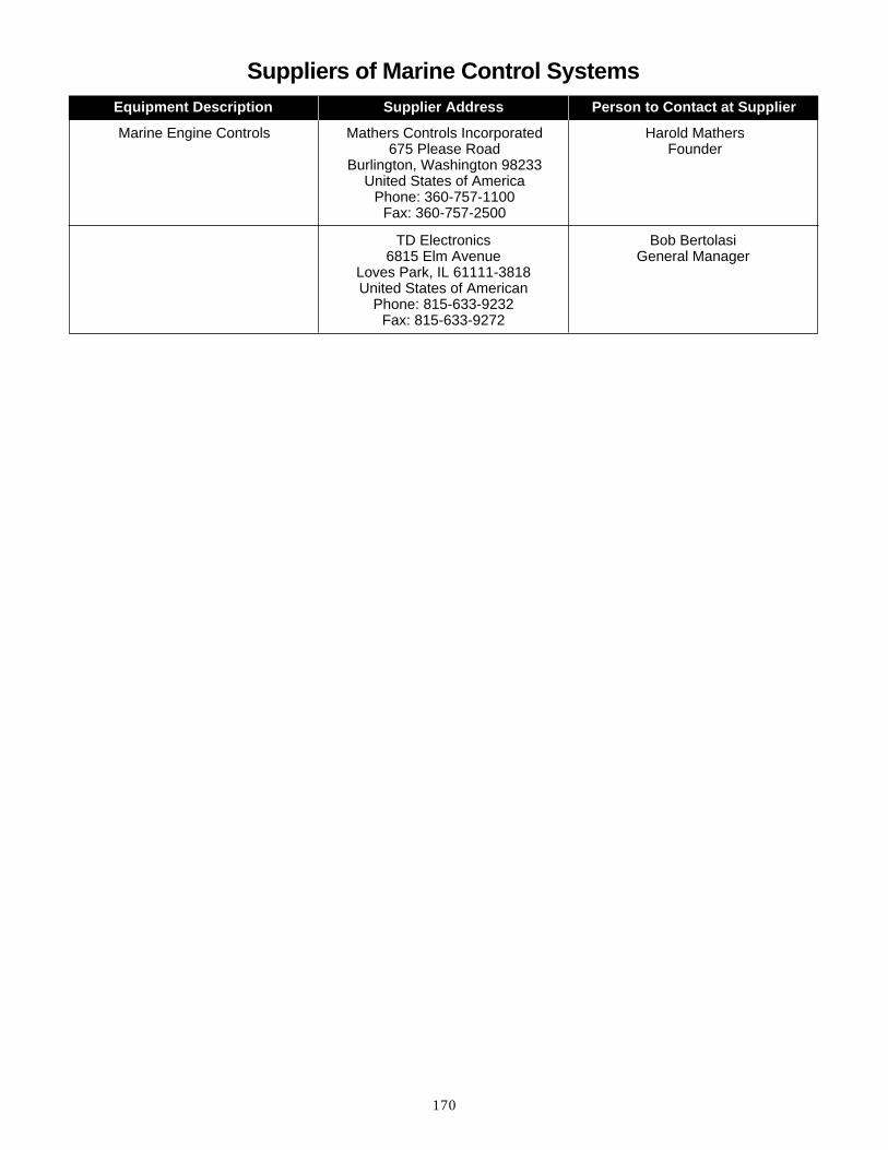
170
Suppliers of Marine Control Systems
Marine Engine Controls Mathers Controls Incorporated675 Please Road
Burlington, Washington 98233United States of America
Phone: 360-757-1100Fax: 360-757-2500
Harold MathersFounder
TD Electronics6815 Elm Avenue
Loves Park, IL 61111-3818United States of American
Phone: 815-633-9232Fax: 815-633-9272
Bob BertolasiGeneral Manager
Equipment Description Supplier Address Person to Contact at Supplier

LEBM7301 ©1997 Caterpillar Inc. Printed in U.S.A.
®