motiva port arthur refinery sbu2 commissioning and start-up · 2020-03-03 · restricted presenters...
TRANSCRIPT

RESTRICTED
Presenters
John Bagley – Motiva Port Arthur
Jim Jenkins – Shell International E&P
Shamara Manora – Motiva Port Arthur
September 2012
Motiva Port Arthur Refinery SBU2 Commissioning And Start-Up

RESTRICTED
OVERVIEW
Introduction
New Sulfur Complex Overview
Challenge Statement and Details
Conclusion
2 CONFIDENTIAL

RESTRICTED
Sulfur Complex 2 Design Basis
Need To Support 325 MBPD Refinery Crude Expansion
SWS2/3
800 GPM Each Unit
ARU5/6
3900 GPM Each Unit
SRU5/6/7
350 LTD Air Only Each Train
525 LTD Air With Oxygen Enrichment (28%) Each Train
CONFIDENTIAL

RESTRICTED
New Sulfur Complex Overview
CONFIDENTIAL

RESTRICTED CONFIDENTIAL

RESTRICTED
East/West Pipe Rack
(Our Conference Room)
CONFIDENTIAL CONFIDENTIAL

RESTRICTED
East/West Pipe Rack
CONFIDENTIAL CONFIDENTIAL

RESTRICTED
SWS Configuration
SWS2
– “Clean” – Non-Phenolic Water Service
– Water Segregation From “New Side Only”
– Side Draw For Wash Water Recycle
SWS3
– Phenolic Sour Water Service
– Water Integration With SBU1 (Old Side)
– Stripped Sour Water Recycle
CONFIDENTIAL CONFIDENTIAL

RESTRICTED
SWS2
CONFIDENTIAL
CLEAN SOUR WATER DEGASSING
DRUM
CLEAN SOUR WATER
VAPOR RECOVERY
CLEAN SOUR WATER TANK
FINFANS SWS ACID GAS K.O.DRUM HEADER
STR
IPP
ER
TO
WE
R
50#STEAM
WASH WATER
ASTU
CONFIDENTIAL

RESTRICTED
SWS3
CONFIDENTIAL
PHENOLIC SOUR WATER DEGASSING
DRUM
PHENOLIC SOUR WATER
VAPOR RECOVERY
PHENOLIC SOUR WATER
TANK
FINFANS SWS ACID GAS K.O.DRUM HEADER
STR
IPP
ER
TO
WE
R
50#STEAM
WASH WATER
ASTU
CONFIDENTIAL

RESTRICTED
SWS3 Degassing Drum
CONFIDENTIAL CONFIDENTIAL

RESTRICTED
ARU Configuration
3900 GPM Each Train
– Dedicated Or Combined Amine Separators
– Rich Flash Drum
– Swing & Surge Tank Capability
– Lean And Rich Transfer Lines With SBU1
– Active Flow Maintained
– AAG Supplied To SBU2 Only
– Dedicated SBU2 Acid Gas Header
– Segregated From SBU1
CONFIDENTIAL CONFIDENTIAL

RESTRICTED
ARU
CONFIDENTIAL
SEPARATOR
SEPARATOR
RICH AMINE
LEAN AMINE COOLERS
RE
GE
NE
RA
TOR
TO
WE
RA
RU
5
AM
INE
FI
LTER
S
LEAN AMINE
REFLUXDRUM
50# STEAM
CONDENSATE
ARU6AMINE ACID GASINTERCONNECT
LEAN AMINE SURGE TANK
OVERHEAD FINFAN
CONDENSERS

RESTRICTED
Amine Seperators
CONFIDENTIAL CONFIDENTIAL CONFIDENTIAL

RESTRICTED
Amine Carbon Filter
CONFIDENTIAL CONFIDENTIAL CONFIDENTIAL

RESTRICTED
SRU Configuration
3 Two Stage Claus Trains
– Dedicated Tail Gas Unit For Each Train
– Oxygen Enrichment (28%)
– 2 Zone Reaction Furnace Configuration
– High Pressure Steam WHB (2 Pass)
– Shell Sulfur Degassing
– Three Compartment Pit Design
– Remote Sulfur Loading
CONFIDENTIAL CONFIDENTIAL CONFIDENTIAL

RESTRICTED
SRU
CONFIDENTIAL
THERMAL REACTOR
WASTE HEAT BOILER1ST PASS
WASTE HEAT BOILER2ND PASS
WASTE HEAT BOILER STEAM DRUM
600# STEAM HEADER
OXYGEN 1ST SULFURCONDENSER
1ST CLAUSCONVERTER
2ND SULFUR CONDENSER
2ND CLAUS CONVERTER
FINAL SULFUR CONDENSER
SULFUR TANK
SULFUR LOADING RACK
TGTU
1ST CHAMBER
2ND CHAMBER
3RD CHAMBER
AC
ID G
AS
K.O
.DR
UM
AMINE ACID GASINTERCONNECT
SWS GASINTERCONNECT
SW
SK
.O.D
RU
M
ATMOS.
CONFIDENTIAL

RESTRICTED
Thermal Reactor & WHB
CONFIDENTIAL

RESTRICTED
Thermal Reactor
CONFIDENTIAL CONFIDENTIAL CONFIDENTIAL CONFIDENTIAL

RESTRICTED
Converters
CONFIDENTIAL CONFIDENTIAL CONFIDENTIAL CONFIDENTIAL

RESTRICTED
Condensers
CONFIDENTIAL CONFIDENTIAL CONFIDENTIAL CONFIDENTIAL

RESTRICTED
Sulfur Pit
CONFIDENTIAL CONFIDENTIAL CONFIDENTIAL CONFIDENTIAL

RESTRICTED
Pre-Loading Sulfur Pit
CONFIDENTIAL CONFIDENTIAL CONFIDENTIAL CONFIDENTIAL

RESTRICTED
ControTrace – Pit Vent Line
CONFIDENTIAL CONFIDENTIAL CONFIDENTIAL CONFIDENTIAL

RESTRICTED
TGTU Configuration
3 SCOT Units
– Dedicated For Each Claus Train
– “Standard” Temperature SCOT
– 650 PSI Superheated Steam Self Supplied
– Incinerator Waste Heat Recovery
– Robust MDEA Stripper
– Formulated MDEA
– Aqueous Ammonia For Quench Buffer
CONFIDENTIAL CONFIDENTIAL CONFIDENTIAL CONFIDENTIAL

RESTRICTED
TGTU
CONFIDENTIAL
INCINERATOR BURNER
WASTE HEAT
BOILER
STEAM DRUM
600#SUPERHEATED
STEAM
INC
INER
ATO
RS
TAC
K
ATMOS.
NATURAL GAS
AB
SO
RB
ER
TGTU REACTOR
TAILGAS FROM SRU
WASTE HEAT BOILER
QU
EN
CH
TO
WE
R
STR
IPP
ER
REBOILER
RE
FLU
X D
RU
M
SRU ACID GAS
K.O.DRUMCOND.
CONFIDENTIAL CONFIDENTIAL

RESTRICTED
Incinerator
CONFIDENTIAL CONFIDENTIAL CONFIDENTIAL CONFIDENTIAL CONFIDENTIAL

RESTRICTED
Incinerator
CONFIDENTIAL CONFIDENTIAL CONFIDENTIAL CONFIDENTIAL CONFIDENTIAL

RESTRICTED
Incinerator
CONFIDENTIAL CONFIDENTIAL CONFIDENTIAL CONFIDENTIAL CONFIDENTIAL

RESTRICTED
Sulfur Loading Configuration
Remote From SBU2
Jacketed Sulfur Transfer Line
– Approximately 10,000 Feet Of Line
Automated Loading
– Weigh Scale – Auto Stop Fill
– BOL Printed At The Rack
Vapor Scrubbing
CONFIDENTIAL CONFIDENTIAL CONFIDENTIAL CONFIDENTIAL CONFIDENTIAL

RESTRICTED
Sulfur Loading Area
CONFIDENTIAL
Sulfur from Sulfur Pit
Sulfur Storage Tank
Sulfur Loadout
Truck
Sulfur Truck Weigh Scale
Truck Vapor to Scrubber
Tank Vapor to Scrubber
Caustic Storage/Loadout Vent Scrubber
Vent to Atmosphere
Sulfur Storge/Loadout Vent Blower
CONFIDENTIAL CONFIDENTIAL CONFIDENTIAL CONFIDENTIAL

RESTRICTED
Sulfur Loading Area
CONFIDENTIAL CONFIDENTIAL CONFIDENTIAL CONFIDENTIAL CONFIDENTIAL

RESTRICTED
Sulfur Loading Area
CONFIDENTIAL CONFIDENTIAL CONFIDENTIAL CONFIDENTIAL CONFIDENTIAL

RESTRICTED
SLR Panel
CONFIDENTIAL CONFIDENTIAL CONFIDENTIAL CONFIDENTIAL CONFIDENTIAL

RESTRICTED
Provide a safe, reliable way to dryout the refractory in several vessels within three new sulfur recovery units without plant utilities
(i.e. no natural gas, boiler feed water (BFW), etc.)
Challenge Statement and Details
CONFIDENTIAL CONFIDENTIAL CONFIDENTIAL CONFIDENTIAL

RESTRICTED CONFIDENTIAL CONFIDENTIAL CONFIDENTIAL CONFIDENTIAL

RESTRICTED
Refractory
A refractory material is one that retains its strength at high temperatures and are used in linings for furnaces, boilers, incinerators and reactors.
ASTM C71 defines refractories as non-metallic materials having certain chemical and physical properties that make them applicable for structures, or as components of structures, that are exposed to operating conditions greater than 1,000 °F.
Refractory materials must be chemically and physically stable at high temperatures. Depending on the operating environment, they need to be
– resistant to thermal shock
– be chemically inert to the process (acidic, neutral or basic refractory material)
– have specific ranges of thermal conductivity
– consider coefficient of thermal expansion
The refractory lining in these vessels use a combination of shaped (firebrick) and unshaped/monolithic (castable) refractories.
CONFIDENTIAL CONFIDENTIAL CONFIDENTIAL CONFIDENTIAL

Refractory
All refractory require anchorage systems such as wire formed anchors, formed metal or ceramic tiles to support the refractory linings.
The anchorage used for refractory on roofs and vertical walls are more critical as they must remain able to support the weight of refractory even at the elevated temperatures and operating conditions.
These units employ a “steerhorn” anchor for support
CONFIDENTIAL CONFIDENTIAL CONFIDENTIAL CONFIDENTIAL

RESTRICTED
Terminology
CONFIDENTIAL
Curing - The process of bond formation with water at ambient temperature in cement based castables while
keeping the refractory material wet or the surrounding atmosphere humid for 24-48 hours prior to applying
heat for drying.
Dryout - Dry out is the process for removing both the mechanical water and chemical water from the refractory.
– Free or Physical Water – Excess water not retained in the bond structure that boils off at normal temperatures for
free water.
– Chemically Combined Water - Water that is tied up in the cement bond structure and released in stages at
elevated temperatures.
CONFIDENTIAL CONFIDENTIAL CONFIDENTIAL CONFIDENTIAL

RESTRICTED
Importance of Curing and Dryout
An improperly performed heat-up can trap moisture within the refractory.
– If residual moisture remains in the refractory, this moisture can interact negatively with process chemicals, such as sulfur, that should not be exposed to moisture.
– Water trapped within a refractory leads to a pressure buildup and the potential for dangerous explosive spalling.
A consistent dry-out ensures that a dual-component lining will not form slip planes where surface refractory “droops” or separates from anchored refractory.
All of these problems result in a shortened refractory life, and possibly even damage to costly equipment.
A controlled dry-out gradually forces the migration of free and chemically held water through the refractory lining, removing moisture.
Ceramic bonding occurs when dry-outs are performed at temperatures approximating 1,000°F (538°C). With the application of both heat and pressure, thermal penetration assures cross-sectional ceramic bonding within the refractory. This bond equates to refractory strength. With improved bonding, refractory campaign life should increase.
CONFIDENTIAL CONFIDENTIAL CONFIDENTIAL CONFIDENTIAL
RESTRICTED
Conventional Castables
CONFIDENTIAL
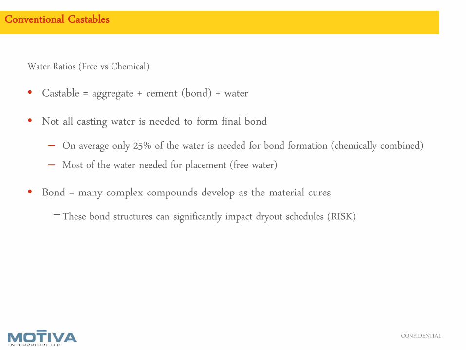
Water Ratios (Free vs Chemical)
• Castable = aggregate + cement (bond) + water
• Not all casting water is needed to form final bond
– On average only 25% of the water is needed for bond formation (chemically combined)
– Most of the water needed for placement (free water)
• Bond = many complex compounds develop as the material cures
−These bond structures can significantly impact dryout schedules (RISK)
CONFIDENTIAL CONFIDENTIAL CONFIDENTIAL CONFIDENTIAL

RESTRICTED
Conventional Castables
CONFIDENTIAL
Water Ratios (Free vs Chemical)
Free water fills and creates porosity
Bond structures formed in curing temperatures below manufacturers' guidelines can result in bond formations that result in:
– Higher % chemical water, lower % free water
– Less free water means less porosity
– More chemical water released at higher temperatures deeper in the lining passing thru lower
porosity material
– SIGNIFICANT increase in dryout time and risk
CONFIDENTIAL CONFIDENTIAL CONFIDENTIAL CONFIDENTIAL

RESTRICTED
Conventional Castables
CONFIDENTIAL
Free water
• Fills and adds to porosity of the material
• Not combined in bond structure
• Moves at approximately 212°F in lining
• The first hold point is the most critical for cement-bonded refractory for removing the mechanical water and is usually between 220ºF and 400ºF.
• The mechanical water is turned into steam and forced out of the refractory by the heat
Chemically combined water
• Used in development of bond as temperature increases
• The upper hold points remove the chemical water and form the final bond within the refractory for maximum strength.
• Some of the water is released at various temperatures, examples might be:
400°F
600°F
800°F
1,000 °F
Heat-up must be
designed to accommodate
type & thickness
CONFIDENTIAL CONFIDENTIAL CONFIDENTIAL CONFIDENTIAL

Heat-Up Guidelines

RESTRICTED
Complex Linings
Sections of linings that would normally require different dryout schedules
– Changes in lining composition (number of layers)
– Significant change in lining thicknesses (even if the same materials)
– Changes in material or refractory product form (ie. Cement castable, chem-bonded
castable, refractory plastic, etc.)
Normally increases the dryout time to account for all of the critical release points
CONFIDENTIAL CONFIDENTIAL CONFIDENTIAL CONFIDENTIAL CONFIDENTIAL

RESTRICTED
Lining As Installed
CONFIDENTIAL
Unit size:
• 12’6” ID Shell X ~48’ long
Water behind 9” brick:
• 20,500 pounds, or
• 2500 gallons
CONFIDENTIAL CONFIDENTIAL CONFIDENTIAL CONFIDENTIAL

RESTRICTED
Thermal Profiles
9˝HOTFACE
BRICK
3˝DENSE
CASTABLE
3˝INSULATINGCASTABLE
STEELSHELL
1500 ˚F (815 ˚C)1400 ˚F (760 ˚C)1300 ˚F (704 ˚C)1200 ˚F (649 ˚C)1100 ˚F (593 ˚C)1000 ˚F (538 ˚C)
900 ˚F (482 ˚C)800 ˚F (427 ˚C)700 ˚F (371 ˚C)600 ˚F (316 ˚C)500 ˚F (260 ˚C)400 ˚F (204 ˚C)300 ˚F (149 ˚C)200 ˚F (93 ˚C)100 ˚F (38 ˚C)
0 ˚F (-18 ˚C)
Inside Gas VesselTemperature ºF Hot Face ºF Intermediate ºF Backup ºF Shell ºF
200ºF 193 184 149 115250ºF 239 226 174 125300ºF 285 267 199 133350ºF 332 309 223 141400ºF 378 350 247 149450ºF 424 391 270 156500ºF 470 432 293 162550ºF 516 473 316 168600ºF 562 514 339 1751000ºF 931 839 520 223
Mean Temperatures of Refractory Layers
CONFIDENTIAL
Refractory cement has elements that trap many microscopic air pockets in the mix that provide a high degree of insulation.
CONFIDENTIAL CONFIDENTIAL CONFIDENTIAL CONFIDENTIAL

RESTRICTED
Required Utilities & Preliminary Tasks
Instrument Quality Air
Combustion Air
Fuel Supply
Boiler Feed Water
Process Safety Interlocks and Safety Equipment
Complete Boil-Out of New Boilers
Obtaining and managing all these utilities and process parameters was a joint effort between five companies
CONFIDENTIAL CONFIDENTIAL CONFIDENTIAL CONFIDENTIAL

RESTRICTED
Instrument Air Supply
Provide instrument air at 90 psig and a dewpoint of -40 degF for instrumentation and regulator control
Ensured all instrumentation was lined up and energized
CONFIDENTIAL CONFIDENTIAL CONFIDENTIAL CONFIDENTIAL

RESTRICTED
Combustion Air
Electric Combustion Air Blower
– Blowers had a rated capacity of 100,000 ft³/hr
– Primary and Secondary CAB were installed
– Set up of blowers ensured that heat is distributed evenly regardless of a vessel’s geometry.
– Blowers contained a step-down transformer to supply current to the system’s flame failure device. Thus a fan
failure would shut down the burner system.
CONFIDENTIAL CONFIDENTIAL CONFIDENTIAL CONFIDENTIAL

RESTRICTED
Fuel Supply
Provided propane from two 1990 gallon LPG tanks
Liquid propane was converted into gas via four 80 gph direct fired vaporizer units working in parallel
A gallon of liquid propane will become ~36 cubic feet of vapor
A direct fired vaporizer uses a direct flame to vaporize liquid LPG inside a heat exchanger/pressured vessel.
Requiring no electricity, the direct fired vaporizer utilizes LPG itself as its source of energy and provides a constant supply of LPG to the process unit
CONFIDENTIAL CONFIDENTIAL CONFIDENTIAL CONFIDENTIAL

Fuel Supply
= 234,000 ft3/train
= 151,200 ft3/train
= 27,000 ft3/train
= 72,000 ft3/train
CONFIDENTIAL CONFIDENTIAL CONFIDENTIAL CONFIDENTIAL

Fuel Supply
CONFIDENTIAL

Fuel Supply
CONFIDENTIAL CONFIDENTIAL CONFIDENTIAL

Boiler Feed Water
CONFIDENTIAL CONFIDENTIAL CONFIDENTIAL

RESTRICTED CONFIDENTIAL CONFIDENTIAL CONFIDENTIAL CONFIDENTIAL

RESTRICTED
Dryout Equipment Apparatus
The combustion set consisted of a burner, combustion air blower and flame safety control cabinet. All were
interconnected with gas and air hosing.
CONFIDENTIAL CONFIDENTIAL CONFIDENTIAL CONFIDENTIAL

RESTRICTED
Dryout Burner Apparatus
The refractory was heated in accordance with manufactures heat up schedule using a supplemental burner as the heat source.
The burner was mounted onto the equipment within a sufficient distance away from the tube and wall surface to prevent any flame impingement or overheating.
The burner assembly included an integral or an independent observation port to view the flame throughout the dry-out process.
Thermocouples were installed to calculate the average gas temperature throughout the dry out process. Thermocouples were installed at multiple points as directed by the manufacture of the refractory.
A vent was installed in the rear of the equipment to allow for proper venting of the flue gasses.
Boilers had adequate liquid level to prevent WHB tubes, tubesheets, drums, etc from being damaged from over-expansion of these components
CONFIDENTIAL CONFIDENTIAL CONFIDENTIAL CONFIDENTIAL

Thermal Reactor and WHB Pass 1/2
CONFIDENTIAL CONFIDENTIAL CONFIDENTIAL CONFIDENTIAL

Thermal Reactor and WHB Pass 1/2
CONFIDENTIAL

2nd Sulfur Condenser & SCOT WHB
CONFIDENTIAL

Second Sulfur Condenser
CONFIDENTIAL

SCOT Reactor WHB
CONFIDENTIAL

Incinerator Dryout Apparatus
CONFIDENTIAL

Incinerator
CONFIDENTIAL

SCOT Reactor and Claus Converters
CONFIDENTIAL

Claus Converters and SCOT Reactor

RESTRICTED
Burner Management Plan
Burner
– A high velocity, excess air burner
– Rated capacity of 10MM BTU/hr with a high turndown ratio approaching 100/1.
– The turndown capability enabled precise temperature control at full combustion air rates ensuring minimum
gradients throughout the heat cycle.
– The high velocity provided a turbulent atmosphere within the vessel or duct eliminating stagnant areas and
minimizing temperature differentials.
Combustion Air Blower
– Blowers had a rated capacities of 100,000 ft³/hr.
– Blowers contained a step-down transformer to supply current to the system’s flame failure device. Thus a fan
failure would shut down the burner system.
– Set up to ensure that heat is distributed evenly regardless of a vessel’s geometry.
CONFIDENTIAL CONFIDENTIAL CONFIDENTIAL CONFIDENTIAL CONFIDENTIAL

RESTRICTED
Burner Management Plan
Flame Safety Control Cabinet
– The control cabinet contained various valves that control the gas flow rates to the burner
– Automatic safety valves shut down the system when
– Flame failure device, with scanner built into the burner, was unable to detect flame. The combustion sets were
equipped with Fire-eye brand flame failure system. The flame scanner was built deep into the burner body so that
burners in close proximity would not influence the interlock.
Temperature Recorder
– The system consisted of 24-point recorders, producing a continuous permanent chart of all thermocouples.
CONFIDENTIAL CONFIDENTIAL CONFIDENTIAL CONFIDENTIAL CONFIDENTIAL

RESTRICTED
Burner Management Plan
Thermocouples
– Used Type K (chromel-alumel) made of 1/8" stainless steel sheath and 18-gage thermocouple wire.
– Ensured the proper length was used to ensure a satisfactory position inside the vessel.
– All were connected via type K compensating wire and routed as not to interfere with traffic during the dryout
process.
– Skin thermocouples were installed via a capacitor discharge unit to the shell.
Redundant Equipment (e.g. a spare combustion set) was provided as well.
CONFIDENTIAL CONFIDENTIAL CONFIDENTIAL CONFIDENTIAL CONFIDENTIAL

RESTRICTED
Boil Out
The internal surfaces of a new boiler contain deposits of residual oil, grease and protective coating inherent in manufacturing procedures.
It is important that these deposits be removed from the heating surfaces since this contamination will lower the heat transfer rate and possibly cause overheating of pressure vessel metal.
These deposits can generally be removed by an alkaline boil-out
Boil-out chemicals are highly caustic. Caustic Soda Ash will produce a violent flash if introduced to water too rapidly. Employees handling the chemicals must wear protective equipment, I.E. Goggles, gloves, aprons, etc.. and an emergency shower should be nearby. Typically a mild acid like vinegar serves as an antidote.
Boiler Feed Water is needed and a proper steam drum level needs to be maintained
Fire the boiler at the proper temperature as indicated by water treatment specialist(s)
Continue the boil out for at least 60 hours until the blowdown is clean.
When blowdown is clean, remove the heat source, and allow the unit to cool gradually.
Drain the boiler when water temperature drops below 200°F.
Remove the inspection covers, flush the system with treated water at least three to four times.
Inspect pressure parts internally. If any remnant oil is found, repeat the boil-out procedure.
Take the necessary precautions to protect boiler internal surfaces from corrosion by utilizing the appropriate lay up
CONFIDENTIAL CONFIDENTIAL CONFIDENTIAL CONFIDENTIAL CONFIDENTIAL

Timeline
CONFIDENTIAL CONFIDENTIAL CONFIDENTIAL CONFIDENTIAL CONFIDENTIAL

RESTRICTED
Ensuring Safety Always
Steam Drum Low Level Interlock
Steam PRVs with Silencer on new equipment
Temporary boiler high pressure steam shutdown and fire detection shutoff
Temperature controls
Air to Gas Ratio Controls
LPG Tank location, PRVs, effluent line design and pressure testing
LEL monitoring
CONFIDENTIAL CONFIDENTIAL CONFIDENTIAL CONFIDENTIAL CONFIDENTIAL

RESTRICTED
Lessons Learned
Of the 27 vessels in need of dryout, there was one vessel that needed refractory repairs
Partially dryout was not favorable due to the potential of alkali hydrolysis
No more than a few weeks (usually not more than 3 or 4) should pass after installation until dryout should begin. Providing some kind of air movement (such as a dehumidifier or dryer of some kind) would extend that time somewhat.
Heat transfer calculations and resulting skin temperatures for various hot face temperatures allowed the engineering team to decide on the max heat-up temperature during dry-out for the various vessels
The hold temperatures for dryout are based on the thermal conductivity amongst the refractory and the water of hydration temperature throughout the refractory. For example, the 4th water of hydration temperature for the 3” insulating castable in the Thermal Reactor is reached around 825-850F. This requires getting the intermediate castable layer to above 1000F. Thus, the target dry-out temperature at the hot face has to be 1500F.
CONFIDENTIAL CONFIDENTIAL CONFIDENTIAL CONFIDENTIAL CONFIDENTIAL

RESTRICTED
Conclusion
New Sulfur Complex
– Two – 3900 gpm capcaity ARUs
– Two – SWS (Phenolic and Clean)
– Three – 507 LTPD SRU Trains
Need Refractory Dryout in a Tight Startup Schedule with limited plant utilities
Provided ways to get
– Instrument Quality Air
– Boiler Feed Water
– Burner Assembly
– Boil Out, Curing and Dryout
CONFIDENTIAL CONFIDENTIAL CONFIDENTIAL CONFIDENTIAL CONFIDENTIAL
A Disciplined Plan, Purposely Executed, as ONE Site, with Full Transparency, and NO Freelancing…....And Before You Know
it, We’re Running an Entire Refinery!!!

Questions?
CONFIDENTIAL CONFIDENTIAL CONFIDENTIAL CONFIDENTIAL CONFIDENTIAL