motion control solutions - panasonic electric works sales western
TRANSCRIPT

Motion Control SolutionsMinas A4/A4N/E Servo Drives/FP-Series PLCs
04/2008

22
Page 3
Page 11
Page 29
2008Panasonic Electric Works Europe AG
Made in Germany
© 2008Panasonic Electric Works Europe AG
Made in Germany
Control Configurator PMControl Configurator PM
20082008
Overview
Panasonic Motion Control Solutions
FP-SERIESThe compact FP (Sigma) is suitable for most applications. The FP (Sigma) PLC itself has powerful features for up to two axes. Add FP (Sigma) positioning units to control up to10 inde-pendent axes. The new FP-X PLC with transistor outputs offers functionality similar to the FP(Sigma). The FP2/FP2SH is also suitable for complex positioning applications, while the com-pact FP0 and FP-e can handle simple positioning tasks. RTEX units for FP (Sigma) and FP2offer real-time access to multiple Minas A4N drivers.
MINAS A4/A4N/A4P/E SERIES SERVO MOTORS AND DRIVERSPowerful servo drives with cutting edge technology, high power density and a power range of 50W to 5kW. [Minas A4/A4N/Minas E (100 to 400W)].
SOFTWAREUse any of the built-in functions for FP (Sigma) or FP-X for up to two axes or the certified Motion Control Library for more complex tasks that require positioning units. PANATERM® and Configurator PM allow set-up, tuning, monitoring and analysis of the driven system.
A
C
B
AC
B
MINAS A4/A4N/A4P/E SERIES SERVO DRIVES
FP-SERIES PLCs
SOFTWARE
04/2008

3
PLC FP0 / FPe FP-X FP (Sigma FP2 / FP2SHType Transistor Relay with cassette Transistor Relay Transistor
Number of axes supported
2x5kHz (1x10kHz) pulse train
–4 (2x100kHz+2x20kHz) pulse train
–2x60kHz(1x100kHz) pulse train
–
Functions Positioning –Linear interpolation 2x100kHz +2x20kHz
–Linear interpolation 100kHz, circular 20kHz
–
Number of axes supported using expansion units
–2x80kHz (1x100kHz) pulse train
–8x500kHz (2MHz line driver) pulse train, 16 x Ethernet 100MHz (RTEX)
64 (88 for FP2SH) x 500kHz (2MHz line driver) pulse train, 112 x Ethernet 100MHz (RTEX)
Number of axes per expansion unit
– 1 pulse train –1 or 2 pulse train, 2,4 or 8 via Ethernet (RTEX)
1 or 2 pulse train, 2, 4 or 8 via Ethernet (RTEX)
Functions –Independent positio-ning,linear interpolation
–Independent positioning (pulse train), linear interpolation 2 or 3 axes, circular 2 axes, spiral 3 axes (Ethernet/RTEX)
FP-Series PLCsOverview
A
B
E
FP (SIGMA)Program capacity: 32k steps
Memory capacity: 32k words
Expansion capacity: 4 modules (left side) 3 modules (right side) up to 384 I/Os
Processing speed: 0.32μs/basic instruction
FP-XProgram capacity: FPXC30, FPXC60 32k steps
FPXC14 16k steps
Memory capacity: 32k words
Expansion capacity: Up to 8 units + up to 2 cassettes for FPXC14 or + up to 3 cassettes for FPXC30/C60
Up to 300 I/Os possible
Processing speed: 0.32μs/basic instructions
FP2 / FP2SHProgram capacity: FP2 16 or 32k steps
FP2SH 60 or 120k steps
Memory capacity: FP2 6000 wordsFP2SH 10,240 words
Expansion capacity: Up to 28 modules or 2048 I/Os
Processing speed: FP2 0.35μs/basic instruction FP2SH 0.03μs/basic instruction
04/2008

4
Positioning with FP (Sigma)
FP-Series PLCs
Pulse output of up to 4Mpps and high-speed startup at 0.005ms enable linear servo motor control.
FP (Sigma) positioning unit
The linear and circular interpolation functions support a wide va-riety of applications.
These interpolation functions enable simultaneous two-axis control, which can support applications that up to now have been difficult to handle using conventional compact PLCs.
Error detection is available by using the high-speed counter in com-bination.
Unexpected accidents, such as errors in the driving system, can be de-tected by setting the counter so that it counts the feedback pulses from the encoder during positioning.
Smooth acceleration/deceleration enables smooth startup. Accelerates/decelerates in a maximum of60 steps depending on preset parameters
Open-loop control
Motordriver
Pulseroutput Motor
Encoder(for error detection)
FP (Sigma)positioning unit
Pulser inputfrom the encoderCounts feedback
pulses from the encoder to detect errors
Adhesive
Linear interpolation Circular interpolation
CW/CCW is also supported.
Pulse+Sign method. Cost reduction of the whole system can be achieved by using FP (Sigma) with small stepping motors or servo motors that do not support the pulse-and-sign method.
CW/CCW method Pulse+Sign method
The control unit on its own can provide two-axis control.
The control unit has a pulse output of 100kpps and startup speed of 0.02ms, which provide sufficient performance for normal po-sitioning.
Circular interpolation
Positioning locusCurrent position S(X 5000, Y 8660)
Passing position P(X 9396, Y -3420)
Target position E(X 8660, Y -5000)
A center-radius setting method is also available.
Convenient and easy programming and selectable home return mode.
• Uses a data table for setting parameters, such as startup speed, target speed, acceleration/de-celeration time.
• Comes with dedicated instructions for each mode: trapezoidal control, home return, JOG opera-tion, free table operation, linear interpolation and circular interpolation.
• The home return method is selectable depending on the design, e.g. when only a single sensor is being used.
• Output of the deviation counter reset signal upon completion of return to home position is also available.
Type Output type Product number
FP (Sigma) CPU Transistor output type NPN FPG-C32T2H-A
FP (Sigma) CPU Transistor output type PNP FPG-C28P2H-A
Type Output type Product number
1-axis type Transistor output type FPGPP11
2-axis type Transistor output type FPGPP21
1-axis type Line driver output type FPGPP12
2-axis type Line driver output type FPGPP22
Unit type and product number
The FP (Sigma) positioning unit supports ultra-high speed linear servo motors.
All-purpose device capable of linear interpolation and circular interpolation.
Example
Centerposition O(Xo, Yo)
(Sigma) (Sigma)
A
04/2008

5
+
Positioning with FP-X
FP-Series PLCsA
on)
sive
ion
po-
sition S8660)
ng position P96, Y -3420)osition EY -5000)
ber
-A
-A
Built-in 4-axis pulse output (transistor output type).
The transistor output type C14 comes with 3-axis pulse output while C30/40 comes with 4-axis pulse output inside the control unit. Multi-axis control, which previously required a higher-level PLC, additional positioning unit, or two or more PLC units, can now be achieved with only one FP-X transistor output type unit in a small space at a low cost. In addition, as this type does not require a pulse I/O cassette as needed for a relay output type, other function expansion cassettes such as communication or analog input can be attached for more di-versified applications.
Item Specification
Pulse output Max. frequency
C14: 100kHz (CH0,1), 20kHz (CH2)C30, C60: 100kHz (CH0,1), 20kHz (CH2,3)
Output type Transistor output type PNP
Function Trapezoidal control, multi-stage operation, jog operation, origin return, 2-axis linear interpolation
The relay output type can control two axes by using ex-pansion cassettes.
2-axis 80kHz pulse output is possible by attaching two pulse I/O cassettes (AFPX-PLS). This type is also capable of perfor-ming 2-axis linear interpolation. The pulse I/O cassette does not work with the control unit transis-tor output type.
100kHzx 2 axes
20kHzx 2 axes
3-axis control with C14 4-axis control with C30/C60
2-axis linear interpolation simultaneously in two sets (transistor output type).
2-axis linear interpolation simultaneously controls two motor shafts, allowing you, for example, to move a robot arm diagonally. It is used for palletising, component pick and place, XY table control, contour cutting of a PC board, etc. The FP-X transistor output type is capable of simultaneously controlling 2-axis linear interpolation, for the first time in the industry with a compact pulse-output PLC. This unit greatly expands the range of applications as well as providing the added convenience of programming by using the linear interpolation command F175 (SPSH).
Simultaneous control of two mechanisms
Controls two units of 2-axis XY table
Maximumcompositespeed100kHz
Maximumcompositespeed20kHz
Y-axis(CH1)
Y-axis(CH3)
X-axis (CH0) X-axis (CH2)
C30/C60
The relay output type is also capable of 2-axis linear interpolation.
By adding two pulse I/O cassette units, linear interpolation is possible at a maximum composite speed of 80kHz. The command used for this unit is F175 (SPSH) as for the transistor output types.
FP-X perfectly fits the need for low cost “multi-axis positioning control in small-scale equipment”.
FP-X type overview
Power supply Output type In-puts
Out-puts
AFPXC14TD 24VDC Transistor NPN 8 6
AFPXC14T 100 to 240VAC Transistor NPN 8 6
AFPXC14PD 24VDC Transistor PNP 8 6
AFPXC14P 100 to 240VAC Transistor PNP 8 6
AFPXC30TD 24VDC Transistor NPN 16 14
AFPXC30T 100 to 240VAC Transistor NPN 16 14
AFPXC30PD 24VDC Transistor PNP 16 14
AFPXC30P 100 to 240VAC Transistor PNP 16 14
FP-X type overview
Power supply Output type In-puts
Out-puts
AFPXC60TD 24VDC Transistor NPN 32 28
AFPXC60T 100 to 240VAC Transistor NPN 32 28
AFPXC60PD 24VDC Transistor PNP 32 28
AFPXC60P 100 to 240VAC Transistor PNP 32 28
XY table + processing head Semiconductor wafer takeout blade
First axis80kHz
Secondaxis
80kHz
04/2008

6
FP2 and FP2SH positioning units
FEATURESMaximum 4Mpps command gives high-speed, high-precision positioning.
0.005ms high-speed drive reduces tact-time (start-up time is the time from reception of the CPU unit start-up command to release of the pulse output by the positioning unit).
4 axes per unit means versatility and saves space.
S (sight-shaped) acceleration/deceleration function provides smooth starting and stopping.
Feedback pulse count function makes output pulse counting possible for encoders, etc.
The pulse input function allows users to generate pulses manually to adjust machines, for example.
•
•
•
•
•
•
Operation modes:
E-point control
P-point control
Homing function
Jog operation function
Pulser input function
Interpolation
Single speed acceleration/deceleration
Multistage acceleration/deceleration
Fast startup of 0.02 or 0.005ms makes cycle time reduc-tion possible
Acceleration /deceleration control: Linear or 4 types of S-curve: Sine, quadratic, cycloid and cubic curves (for smooth startup and stopping)
•
•
•
•
•
•
•
•
•
•
FP-Series PLCsA
FP2 CPU typesType Program capacity Product number
FP2 Standard CPU 16k steps FP2C1
FP2SH CPU 60k steps FP2C2
FP2SH CPU 120k steps FP2C3
FP2 positioning unitsNumber of axes Output type Product number
2 Transistor FP2PP21
2 Line driver FP2PP22
4 Transistor FP2PP41
4 Line driver FP2PP42
FP2 power suppliesSupply voltage Power Product number
200–240VAC 2.5A FP2PSA2
100–240VAC 5A FP2PSA3
FP2 backplanesDescription Product number
FP2 backplane 5 modules FP2BP05
FP2 backplane 7 modules FP2BP07
FP2 backplane 9 modules FP2BP09
FP2 backplane 12 modules FP2BP12
FP2 backplane 14 modules FP2BP14
UP TO 4 AXESPER POSITIONING MODULE:
Motor
Motor
Driver
Driver
4-axis typeFP2PP42
Driver
Driver
Motor
Motor
04/2008

7
RTEX positioning units for FP (Sigma) and FP2/FP2SH
A FP-Series PLCs
er
er
er
REAL-TIME ETHERNET SERVO SYSTEMFOR MINAS A4N SERVO DRIVES
SYSTEM CONFIGURATION
ADVANTAGES:Easy control of network servos with an ultracompact PLC.
Allows highly accurate control of multi-axis positioning using high-speed 100Mbps communication.
Commercial LAN cables greatly reduce wiring costs.
New product lineup includes a new 2-axis unit in addition to the 4-axis and 8-axis units.
Dedicated software tool ConfiguratorPM provides total support, from configuration and startup to monitoring.
Includes manual pulser input allowing support for precision teaching.
•
•
•
•
•
•
No. of positioning units per RTEX unit
FP (Sigma): 2 units
FP2: 14 units (limited by consumption current)
Control of 2 to 8 axes in one positioning unit
Commercially available LAN cable(Ethernet category 5 shielded type)
CPU unitTool port
Positioning unit RTEX dedicated software toolConfigurator PM
Programming toolControl FPWIN Pro
PANATERM Vers. 3.70.1 and higher
Software tool for Minas A4/AN servo drives
I/O signals, such as origin proximity, limit,
etc., sent to A4N.
Positioning units for FP (Sigma) and FP2 PLCs support Minas A4N network servo drives. A mutually optimised system consisting of PLC and servo drive greatly simplifies installation.
04/2008
FP Positioning unit RTEX Configuration example: 16 axes + I/O (256)
FP Dedicated Expansion Unit
(Max. of 4 units in combination with Positioning Unit)
Positioning Unit RTEX
(Max. 2 units)Control Unit
FP /FP0 Common Expansion Unit
(Max. 3 units)
Pulser InputTerminal
Network Port(Transmit)
Monitor LEDsStatus DisplayLink StatusError DisplayPulser Input Status
Network Port(Receive)
Pulser InputTerminal
Network Port(Transmit)
Monitor LEDsStatus DisplayLink StatusError DisplayPulser Input Status
Configuration example: 8 axes x 14 modules = 112 axes
Master backplane
Expansion backplane
FP2/FP2SH Positioning Unit RTEX
Network Port(Receive)
8
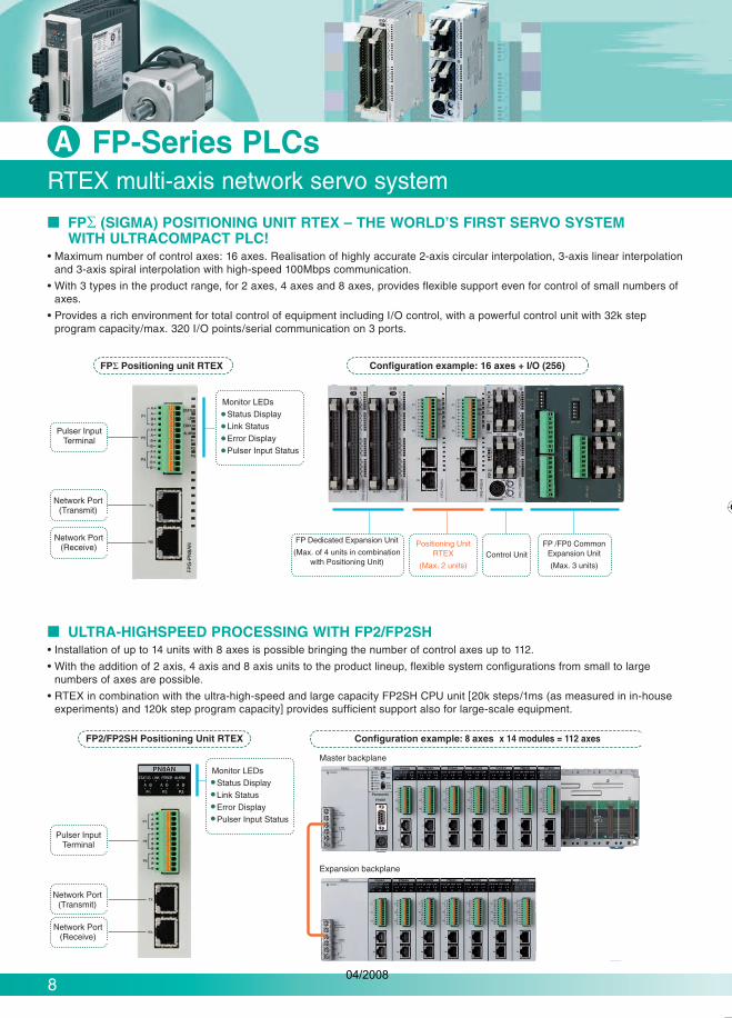
RTEX multi-axis network servo system
FP-Series PLCsA
FP (SIGMA) POSITIONING UNIT RTEX – THE WORLD’S FIRST SERVO SYSTEMWITH ULTRACOMPACT PLC!
• Maximum number of control axes: 16 axes. Realisation of highly accurate 2-axis circular interpolation, 3-axis linear interpolation and 3-axis spiral interpolation with high-speed 100Mbps communication.
• With 3 types in the product range, for 2 axes, 4 axes and 8 axes, provides flexible support even for control of small numbers of axes.
• Provides a rich environment for total control of equipment including I/O control, with a powerful control unit with 32k step program capacity/max. 320 I/O points/serial communication on 3 ports.
ULTRA-HIGHSPEED PROCESSING WITH FP2/FP2SH• Installation of up to 14 units with 8 axes is possible bringing the number of control axes up to 112.
• With the addition of 2 axis, 4 axis and 8 axis units to the product lineup, flexible system configurations from small to largenumbers of axes are possible.
• RTEX in combination with the ultra-high-speed and large capacity FP2SH CPU unit [20k steps/1ms (as measured in in-house experiments) and 120k step program capacity] provides sufficient support also for large-scale equipment.
04/2008

Servo AmpMINAS A4N
Commercially available LAN cable(Ethernet category 5e shielded type)
Data communication flow
Servo AmpMINAS A4N
Keine Verdrahtung erforderlich
No wiringrequired Sensor signal
Save wiring
Servo AmpMINAS A4N
Sensor signal Sensor signal Sensor signal
Reduction in wiring errors and debug time
9
RTEX multi-axis network servo system
FP-Series PLCsA
tion
of
e
BROAD REDUCTION IN WIRING COSTSRealtime Express* uses commercially available LAN cables as wiring for its network. In terms of cost efficiency, availability and workability, this is a great benefit.* Matsushita Electric Industrial network servo systems
HIGH RELIABILITY WITH LOOP WIRINGTransmitted and received data in serial communication is normally sent and received at frequent intervals in the same cable making the communication state extremely sensitive to environmental conditions such as noise. However, by using loop wiring as shown in the figure below, Realtime Express provides high reliability by creating smooth communication conditions with the data flow al-ways in the same direction. In addition, by utilising the 100Mbps high communication speed, Realtime Express reads the data transmissions which occur every 0.5ms twice and carries out data transfer in the extremely short period of 1ms, further improving reliability.
ADVANCED WIRING METHODSensor input (origin proximity, limit) is wired directly to the servo amp of each axis and the signal is transferred through the network to the positioning unit. This enables you to check at a glance which sensor input is connected to which axis. Wiring errors are re-duced and the time required for debugging shortened, especially when the system deals with large numbers of axes. In addition, even if the positioning unit and servo amp are far apart, it is not necessary to wire the signal from a sensor which is close to the servo amp to the distant positioning unit, further reducing the amount of wiring.
04/2008

10
RTEX multi-axis network servo system
FP-Series PLCsA
FUNCTIONS
Operating patterns
• E-point trapezoidal control (PTP control)
• P-point change speed control (CP control)
• C-point repeated trapezoidal control (PTP control)
Low speed test operation mode (speed setting)
• The acceleration/deceleration time and target speed for each point indicated in the data table can be set to a low speed in the range of 1 to 100% without actually changing the data itself. Test operations can be carried out safely by checking the operation of the device at low speed.
Interpolation operation modes
2-axis circular, 2-axis linear• 3-axis spiral, 3-axis linear•
Control methods
• Absolute method, increment method
Auxiliary output
Codes can be output during operation according to the data table number.
•
Movement unit settings
• Pulse (pulse), scale (μm, inch), angle (degree)
JOG operation
Speed and acceleration/deceleration time can be changed during operation.
•
Acceleration/deceleration method
• Linear, S-curve
Pulser input
2-phase quad edge – max. 1Mpps • Division ratio setting possible by specification of numera-
tor/denominator.
•
Origin return
• Origin proximity (DOG) search method
Un
it s
pec
ific
atio
ns
2-axis type 4-axis type 8-axis type
Product number FP (Sigma)/FP2 FPGPN2AN FP2PN2AN FPGPN4AN FP2PN4AN FPGPN8AN FP2PN8AN
Positioning controlfunctions
Control method PTP Control, Cursor Path (CP) Control
Interpolation control 2-axis/3-axis linear interpolation • 2-axis circular interpolation • 3-axis spiral interpolation
Control units Pulse/μm/inch/degree
Position data 600 points for each axis
Backup Parameters and data file can be saved to FROM
Acceleration/deceleration method Linear acceleration/deceleration/S-curve acceleration/deceleration
Acceleration/deceleration time 0 to 10,000ms (1ms units) different settings for acceleration and deceleration are possible
Positioning area (-1,073,741,823 to 1,073,741,823 pulse) increment and absolute specification
Speed control functions Supported with JOG operation (free rund operation)
Origin functions Search method Origin proximity (DOG) search
Creep speed Free settings possible
Other functions Pulser input operation support
Auxiliary output code, auxiliary output contact support
Dwell time support
Co
mm
un
icat
ion
sp
ecif
icat
ion
s Communication speed 100Mbps
Cable Commercially available LAN straight cable (shielded category 5e)
Connection method Ring method
Communication cycle/no. of terminals 0.5ms: Max. 8 axes/system (command cycle: 1ms)
Transmission distance Between terminals: 60m; total length: 200m
SPECIFICATIONS OF RTEX POSITIONING UNITS
04/2008
11
g by
r
ed
-
AN
ation
sible
Main features – increased performance and accuracy
Minas A4/A4P/A4N/E Series Servo Drives
Fast response frequency: 1000Hz (Minas E 400Hz)
Completely adjustment-free, real-time auto-gain tuning
High performance vibration control
Command input up to 2Mpps
Smaller motors and drivers versus the former series
Position, velocity and torque control support – a wide range of applications in one driver
Many more additional functions (Minas A4/A4N/A4P): - Hit & Stop homing, i.e. homing without a switch - Press/Tension control - 8 internal JOG speeds - Others
Minas A4P Drivers- For simple positioning control. No positioning unit or pulse control necessary- Preset up to 60 position points with Software Tool PANATERM- Postioning with digital I/O
•
•
•
•
•
•
•
•
B
Minas series A4 AN A4P A4 AN A4P Minas E
Rated power 50W to 5kW 400W to 7.5kW 50W to 400W
Velocity response frequency 1000Hz 400Hz
Rated/max. rotational speed 3000/5000 rpm
Rated torque 0.16 to 15.8Nm – 1.9 to 57.2Nm – 0.16 to 1.3Nm
Peak torque 0.48 to 47.6Nm – 5.3 to 137Nm – 0.48 to 3.8Nm
Moment of inertia 0.025 to 19.7 x 10⁻⁴kg m² – 2.45 to 288 x 10-4kg m² – 0.021 to 0.2 x 10⁻⁴kg m²
Encoder
IncrementalPulses 2500 pulses/rev.
Resolution 10,000
AbsolutePulses 17-bit resolution
Resolution 131,072
Control method Pulse train Ethernet Digital input Pulse train Ethernet Digital input Pulse train
Control modes Position, velocity, torque, full-closed Position,internal speed
04/2008

12
Details of features
Minas A4/A4N/A4P/E Series Servo Drives B
ADJUSTMENT-FREE OPERATIONHigh-functionality real-time auto-gain tuning
Automatically tunes in real-time to variations in load inertia. Real-time auto-gain tuning for machines with low or high stiffness.
Supports vertical axis applications where the load torque varies depending on rotational direction.
An over-travel detection function prevents the machine from over-travelling during real-time auto-gain tuning.
Enables you to set and check while monitoring real-time automatic gain tuning conditions on the front panel.
•
•
•
•
HIGH-SPEED AND FAST RESPONSEVelocity response (bandwidth) of 1kHz
The instantaneous Velocity Observer detects the motor speed more quickly and with a higher resolution than the previous models.
•
High-functionality real-time auto-gain tuning
Enables low stiffness machines (e.g. belt-driven machines) and high stiffness machines (e.g. short stroke ball-screw driven machines) to be used in high-speed positioning applications.
•
Corresponds to wide frequency range (-1500Hz)Suppresses vibration quickly
4000
3200
2400
1600
800
0
-800
-1600
-2400
-3200
-4000
180
160
140
120
100
80
60
40
20
0
-20
Actual speed (r/min)
W
W
E A4 A4N A4P
E A4 A4N A4P
Legend: not possible
possible
04/2008

13
* On demand only
es
ss.
Details of features
Minas A4/A4N/A4P/E Series Servo Drives B
REDUCTION VIBRATIONAdaptive Filter
Enables the notch filter frequency to automatically follow the machine resonance frequency.
Suppresses judder noise of the machine caused by a chan-ge in the resonance frequency (e.g. resutling from aging ef-fects or changeovers).
•
•
DAMPING CONTROLThe driver is equipped with a 2-channel damping filter. You can suppress vibration occurring at both starting and stopping in low stiffness machines by manually setting up vibration frequencies in 0.1Hz units.
You can switch between the channels with the direction command or with an external input.
Easy setup with input of only frequency and filter values. Incorrect setup values do not result in unstable operation.
•
•
•
Effect of notch filter
Without notch filter With notch filter
50ms/div 50ms/div
Motor movement Machine movement
Without damping control
With damping control
2-CHANNEL NOTCH FILTERSAdaptive Filter
The driver is equipped with 2-channel notch filters which operate independently from the adaptive filter.
Both frequency and width for each of the 2 filters can be set. Frequency can be defined in units of 1Hz.
Suppress judder noise of machines with multiple resonance points.
•
•
•
4P
4P
E A4 A4N A4P E A4
E A4 A4N A4P
A4N A4P
04/2008

14
Additional features
Minas A4/A4N/A4P/E Series Servo Drives B
SETUP SUPPORT WITHHELPFUL MONITORING FUNCTIONS
Faster communication speed of RS232C/RS485 (max. 57,600bps) establishes easy and comfortable operating con-ditions for setup support software PANATERM®.
PANATERM® displays useful status information, e.g. to help you analyse motor problems.
You can enable the panel operation lock via the front panel to inhibit operation, e.g. to prevent parameters from being changed unintentionally.
COMMAND CONTROL MODESOffers you “Position”, “Velocity (including internal 8-speed)” and “Torque” command control modes.
You can select any one of the above command control modes, or select two command control modes by defining the parameters.
You can combine command control modes in a hybrid mode and switch between them.
MONITORING FUNCTIONWITH FRONT PANEL
LED display and analog monitor terminals are installed in the front panel.
Displays “Motor speed”, “Motor torque”, “Position deviation”, “Motor load factor” and “Regeneration load factor”.
You can monitor “Motor speed”, “Motor torque” and “Position deviation" with analog monitor terminals.
TRIAL RUN (JOG)Features the function for trial run (JOG) through the front panel or console (option) without connecting to a host controller.
Shortens machine setup time.
FULL-CLOSED CONTROL(HIGH PRECISION POSITIONING)
Features the full-closed control of position and velocity, using the signals from the linear scale installed on the load side and the high resolution encoder.
Best suited for high precision machines.
•
•
•
•
•
•
•
•
•
•
•
•
•
INRUSH CURRENTSUPPRESSING FUNCTION
The driver is equipped with an inrush suppressing resistor which prevents circuit breaker shutdown of the power supply caused by inrush current at power-on.
Prevents unintentional shutdown of the power supply circuit breaker in multi-axis applications and does not add load to the power line.
REGENERATIONDISCHARGING FUNCTION
Discharges regenerative energy, which is returned from the motor to the driver with a resistor, e.g. stopping a load with a large moment of inertia or with the up-down operation.
Frame A and Frame B drivers do not have a built-in regene-ration discharge resistor. We recommend connecting an opti-onal regenerative resistor.
Frame C – Frame F drivers have a built-in regeneration discharge resistor. However, connecting an optional regene-rative resistor will add even more regenerative capability.
BUILT-IN DYNAMICBRAKE
The driver is equipped with a dynamic brake for emergency stop.
The dynamic brake can be used in the following instances:- Main power OFF- Servo OFF- A protective function- Over-travel inhibit is activated
POSITIONING PULSEUp to 2Mpps of pulse input at positioning control possible.
TORQUE LIMITVALUE SWITCHING
You can set up 2 torque limits and use them for tension control or press & hold control.
APPROVALS
•
•
•
•
•
•
•
•
•
E A4 A4N A4P
E A4 A4N A4P
E A4 A4N A4P
E A4 A4N A4P
E A4 A4N A4P
E A4 A4N A4P
E A4 A4N A4P
E A4 A4N A4P
Legend: not possible
possible
E A4 A4N A4P
E A4 A4N A4P
E A4
A4N A4P
04/2008

15
Overview drivers
es Minas A4/A4N/A4P/E Series Servo Drives B
r ply
uit o
he h a
e-opti-
ne-
cy
s:
.
Minas A4/A4N/A4P
Bas
ic s
peci
ficat
ions
Input power Mai
n c
ircu
it Frame A, B Single phase, 200–240V+10%
50/60Hz-15%
Frame C, D Single/3-phase, 200–240V+10%
50/60Hz-15%
Frame E, F Single/3-phase, 200–240V+10%
50/60Hz-15%
Co
ntr
ol
circ
uit
FrameA to D Single phase, 200–240V
+10%50/60Hz-15%
Frame E, F Single phase, 200–230V+10%
50/60Hz-15%
Environment
Temperature Operating: 0 to 55°C , Storage: -20 to +80°C
Humidity Both operating and storage : 90%RH or less (free from condensation)
Altitude 1000m or lower
Vibration 5.88m/s2 or less, 10 to 60Hz (no continuous use at resonance frequency)
Control method IGBT PWM sinusoidal wave drive
Encoder feedback 17-bit (131,072 resolution) absolute/incremental encoder (on demand only)2500P/r (10,000 resolution) incremental encoder (standard)
External scale feedback Compatible with AT500 series, ST771 by Mitsutoyo
Control signal
Input10 inputs(1) Servo-ON, (2) Control mode switching, (3) Gain switching/torque limit switching, (4) Alarm clearother inputs vary depending on the control mode, (5) CW drive prohibition, (6) CCW driver prohibition
Output6 outputs(1) Servo alarm, (2) Servo ready, (3) Release signal of external brake (4) Zero speed detection,(5) Torque in-limit. Other outputs vary depending on the control mode
Analog signal
Input 3 inputs (16Bit A/D : 1 input, 10Bit A/D : 2 inputs)
Output
2 outputs (for monitoring)(1) Speed monitor (actual motor speed or command speed). Select the content and scale with parameter. (2) Torque monitor [torque command (approx. 3V/rated torque)], deviation counter or full-closed deviation is enabled. Select the content or scale with parameter
Pulse signalInput 2 inputs. Select the exclusive input for line driver or photo-coupler input with parameter
Output 4 outputs. Feed out the encoder pulse (A, B and Z-phase) or external scale pulse (EXA, EXB and EXZ-phase) in line driver. Z-phase and EXZ-phase pulse is also fed out in open collector
Communicationfunction
RS232C 1:1 communication to a host with RS23C interface is enabled
RS485 1:n communication up to 15 axes to a host with RS485 interface is enabled
Front panel (1) 5 keys (MODE, SET, UP, DOWN, SHIFT), (2) LED (6-digit)
Regeneration Frame A, B: no built-in regenerative resistor (external resistor only), Frame C to F: built-in regenera-tive resistor (external resistor is also enabled)
Dynamic brake Setup of action sequence at power-OFF, servo-OFF, at protective function activation and over-travel inhibit input is enabled
Control modeSwitching among the following 7 modes is enabled, (1) Position control, (2) Velocity control, (3) Tor-que control, (4) Position/Velocity control, (5) Position/Torque control, (6) Velocity/Torque control and (7) Full-closed control
Ratedpower
Minas A4 Drivers
Minas A4N Drivers
Minas A4P Drivers
FrameMinas A4, A4N, A4P
Minas E Drivers
FrameMinas E
50WMADDT1205 MADDT1205N MADDT1205P
AMKDET1505P K
100W
200W MADDT1207 MADDT1207N MADDT1207P MLDET2210PL
400W MBDDT2210 MBDDT2210N MBDDT2210P B MLDET2510P
750W MCDDT3520 MCDDT3520N MCDDT3520P C – –
1kWMDDDT5540 MDDDT5540N MDDDT5540P D
– –
1.5kW – –
2kW MEDDT7364 MEDDT7364N MEDDT7364P E – –
3kW MFDDTA390 MFDDTA390N MFDDTA390P
F
– –
4kWMFDDTB3A2 MFDDTB3A2N MFDDTB3A2P
– –
5kW – –
4P
4P
4P
4P
4P
4P
04/2008

16
Ana
log
func
tions
Pos
ition
con
trol
Control input (1) Deviation counter clear, (2) Command pulse inhibition, (3) Electronic gear switching, (4) Damping control switching
Control output Positioning complete (In-position)
Pul
se in
put
Max. command pulse frequency Exclusive interface for line driver: 2Mpps, Line driver: 500kpps, Open collector: 200kpps
Input pulse signal format Support (1) RS422 line drive signal and (2) Open collector signal from controller
Type of input pulse Differential input. Selectable with parameter, [(1) CW/CCW, (2) A and B-phase, (3) Command and Direction]
Electronic gear (division/multi- plication of command pulse) Process the command pulse frequency x (1 to 10,000) x 2(0-17)
1 to 10,000 as a position command input
Smoothing filter Primary delay filter or FIR type filter is selectable to the command input
Analo
g-in
put
Torque limit command input Individual torque limit for both CW and CCW direction is enabled (3V/rated torque)
Instantaneous speed observer Usable
Damping control Usable
Velo
city
con
trol
Control input (1) Zero speed clamp, (2) Selection of internal speed setup, (3) Gain switching or torque limit switching input
Control output Speed arrival (at-speed)
An
alo
gin
pu
t Velocity command input Setup of scale and rotational direction of the motor against the command voltage is enabled with parameter, with the permissible max. voltage input = 10V and 6V/rated speed (default setup)
Torque limit command input Individual torque limit for both CW and CCW direction is enabled (3V/rated torque)
Speed control range 1 : 5000
Internal speed command 8-speed with parameter setup
Soft-start/down function Individual setup of acceleration and deceleration is enabled, with 0 to 10s/1000r/min. Sinusoidal acceleration/deceleration is also enabled
Zero speed clamp Zero speed clamp for internal speed command
Instantaneous speed observer Usable
Speed command filter Usable
Torq
ue c
ontr
ol
Control input (1) CW over-travel inhibition, (2) CCW over-travel inhibition, (3) Zero speed clamp
Control output Speed arrival (at-speed)
An
alo
gin
pu
t Speed command input Setup of scale and CW/CCW torque generating direction of the motor against the command voltage is enabled with parameter, with the permissible max. voltage input = 10V and 3V/rated speed (default setup)
Speed limit input Speed limit input by analog voltage is enabled. Scale setup with parameter
Speed limit function Speed limit value with parameter or analog input is enabled
Full-
clos
ed c
ontr
ol
Control input (1) CW over-travel inhibition, (2) CCW over-travel inhibition, (3) Deviation counter clear, (4) Command pulse input inhibition, (5) Electronic gear switching, (6) Damping control switching
Control output Full-closed positioning complete (in-position)
Pul
se in
put
Max. command pulse frequency Exclusive interface for line driver: 2Mpps, Line driver: 500kpps, Open collector : 200kpps
Input pulse signal format Differential input. Selectable with parameter (1) CCW/CW, (2) A and B-phase, (3) Command and direction
Electronic gear division/multiplica-tion of command pulse Process the command pulse frequency x (1 to 10,000) x 2(0-17)
1 to 10,000 as a position command input
Smoothing filter Primary delay filter is adaptable to the command input
An
alo
g
inp
ut
Torque limit command input Individual torque limit for both CW and CCW direction is enabled (3V/rated torque)
Setup range of division/multiplication of external scale
Setting of ratio between encoder pulse (denominator) and external scale pulse (numerator) isenabled within a range of (1 to 10,000) x 2(0-17) / (1 to 10,000)
Com
mon
Aut
o-ga
intu
ning
Real-time Corresponds to load inertia fluctuation, possible to automatically set up parameters related to notch filter
Normal mode Estimates load inertia and sets up an appropriate servo gain
Fit-gain function Automatically searches and sets up the value which makes the fastest settling time with external command input
Masking of unnecessary input Masking of the following input signal is enabled(1) Over-travel inhibition, (2) Torque limit, (3) Command pulse inhibition, (4) Speed-zero clamp
Division of encoder feedback pulse Set up of any value is enabled (encoder pulses count is the max.)
Prote
ctive
functi
on Soft error Over-voltage, under-voltage, over-speed, over-load, over-heat, over-current and encoder error etc.
Hard error Excess position deviation, command pulse division error, EEPROM error etc.
Traceability of alarm data Traceable up to past 14 alarms including the present one
Damping control function Manual setup with parameter
Set
up Manual 5-push switches on front panel
Setup support software PANATERM® (Supporting OS: Windows95, Windows98, Windows ME, Windows2000, Windows.NET and Windows XP)
Common driver specifications
Minas A4/A4N/A4P Series Servo Drives B
MODE SET
04/2008

17
Connector for communication
Name plate
Name plate
Air current
(from bottom
to top)
Air current
(from bottom
to top)
Connector for control signal connection
Connector for motor connection, CNX3
Connector for encoder connection, CNX4
Earth terminal screws
Connector for main circuit connection, CNX1
Connector for communication
Connector for control signal connection
Connector for motor connection, CNX3
Connector for encoder connection, CNX4
Earth terminal screws
Connector for main circuit connection, CNX1
x.
ed
he
Driver dimensions
s Minas E Series Servo Drives B
FRAME KMKDET1505P
FRAME LMLDET2210P, MLDET2510P
All measurements in mm
04/2008

18
RB2RB3
Rack mount type(Option: Front-end mounting)
Driver dimensions
Minas A4/A4N/A4P Series Servo Drives B
FRAME A
FRAME B
FRAME C
Minas A4N
Minas A4N
Minas A4N
Minas A4
Minas A4
Minas A4
All measurements in mmSame dimensions for Minas A4P drivers
— Rotary switch for node address— Network link LEDs
— RX Ethernet connection
— TX Ethernet connection
— Parallel I/O connection
— Rotary switch for node address— Network link LEDs
— RX Ethernet connection
— TX Ethernet connection
— Parallel I/O connection
— Rotary switch for node address— Network link LEDs
— RX Ethernet connection
— TX Ethernet connection
— Parallel I/O connection
Base mount type(Standard: Back-end mounting)
Base mount type(Standard: Back-end mounting)
Rack mount type(Option: Front-end mounting)
Rack mount type(Option: Front-end mounting)
Base mount type(Standard: Back-end mounting)
Rack mount type
04/2008

19
Mounting bracket(install the standard to back end)
Base mount type(Standard: Back-end mounting)
RB2RB3
5.22.55.2
2.5
50 17.585
5.25.2
881861
8
3.532
200
2.6
Mounting bracket(install the standard to back end)
19
Mounting bracket(install the standard to back end)
Driver dimensions
s Minas A4/A4N/A4P Series Servo DrivesB
FRAME E
FRAME F
FRAME DMinas A4N
Minas A4N
Minas A4N
Minas A4
Minas A4
Minas A4
All measurements in mm
— Network link LEDs
— RX Ethernet connection
— TX Ethernet connection
— Parallel I/O connection
— Network link LEDs
— RX Ethernet connection
— TX Ethernet connection
— Parallel I/O connection
Rotary switch for node address
— Network link LEDsRX Ethernet connectionTX Ethernet connection
— Parallel I/O connection
t typend mounting)
nt typend mounting)
Rack mount type(Option: Front-end mounting)
t typend mounting)
Rotary switch for node address
Rotary switch for node address
04/2008

20
Motor types
Minas A4/A4N/A4P/E Series Servo Drives B
Motorproduct number
Ratedpower
Driverproductnumber
Torque Moment of inertia
*10-4kgm²Shaft Oil
sealHoldingbrake Encoder With IP67
connectorsRated Momentarymax. peak
MSMD5AZP1A
50WMADDT1205 or
MADDT1205N or MADDT1205P
0.16Nm 0.48Nm
0.025 Round Incremental Option available*
MSMD5AZP1C 0.025 Round x Incremental Option available*
MSMD5AZP1D 0.027 Round x x Incremental Option available*
MSMD5AZP1S 0.025 Keyway Incremental Option available*
MSMD5AZP1T 0.027 Keyway x Incremental Option available*
MSMD5AZS1S 0.025 Keyway Absolute Option available*
MSMD012P1A
100WMADDT1205 or
MADDT1205N or MADDT1205P
0.32Nm 0.95Nm
0.051 Round Incremental Option available*
MSMD012P1C 0.051 Round x Incremental Option available*
MSMD012P1D 0.054 Round x x Incremental Option available*
MSMD012P1S 0.051 Keyway Incremental Option available*
MSMD012P1T 0.054 Keyway x Incremental Option available*
MSMD012S1S 0.051 Keyway Absolute Option available*
MSMD022P1A
200WMADDT1207 or
MADDT1207N or MADDT1207P
0.64Nm 1.91Nm
0.14 Round Incremental Option available*
MSMD022P1C 0.14 Round x Incremental Option available*
MSMD022P1D 0.16 Round x x Incremental Option available*
MSMD022P1S 0.14 Keyway Incremental Option available*
MSMD022P1T 0.16 Keyway x Incremental Option available*
MSMD022S1C0.14
Round x Absolute Option available*
MSMD022S1S Keyway Absolute Option available*
MSMD022S1T 0.16 Keyway x Absolute Option available*
MSMD042P1A
400WMBDDT2210 or
MBDDT2210N or MBDDT2210P
1.3Nm 3.8Nm
0.26 Round Incremental Option available*
MSMD042P1C 0.26 Round x Incremental Option available*
MSMD042P1D 0.28 Round x x Incremental Option available*
MSMD042P1S 0.26 Keyway Incremental Option available*
MSMD042P1T 0.28 Keyway x Incremental Option available*
MSMD042S1C 0.26 Round x Absolute Option available*
MSMD042S1S 0.26 Keyway Absolute Option available*
MSMD082P1A
750WMCDDT3520 or MCDDT3520N
or MCDDT3520P2.4Nm 7.1Nm
0.87 Round Incremental Option available*
MSMD082P1C 0.87 Round x Incremental Option available*
MSMD082P1D 0.97 Round x x Incremental Option available*
MSMD082P1S 0.87 Keyway Incremental Option available*
MSMD082P1T 0.97 Keyway x Incremental Option available*
MSMD082S1S 0.87 Keyway Absolute Option available*
MSMA102P1G1kW MDDDT5540,
MDDDT5540Nor MDDDT5540P
3.18Nm 9.5Nm1.69 Keyway x Incremental x
MSMA102P1H 1.88 Keyway x x Incremental x
MSMA152P1G1.5kW 4.77Nm 14.3Nm
2.59 Keyway x Incremental x
MSMA152P1H 2.84 Keyway x x Incremental x
MSMA202P1G2kW
MEDDT7364,MEDDT7364N,MEDDT7364P
6.36Nm 19.1Nm3.46 Keyway x Incremental x
MSMA202P1H 3.81 Keyway x x Incremental x
MSMA302P1G3kW
MFDDTA390, MFDDTA390N, MFDDTA390P
9.54Nm 28.6Nm6.77 Keyway x Incremental x
MSMA302P1H 7.45 Keyway x x Incremental x
MSMA402P1G4kW MFDDTB3A2 or
MFDDTB3A2Nor MFDDT-
B3A2P
12.6Nm 37.9Nm12.7 Keyway x Incremental x
MSMA402P1H 14.1 Keyway x x Incremental x
MSMA502P1G5kW 15.8Nm 47.6Nm
17.8 Keyway x Incremental x
MSMA502P1H 19.7 Keyway x x Incremental x
Minas E
MUMA012P1S100W MKDET1505P 0.32Nm 0.95Nm
0.032 Keyway Incremental
MUMA012P1T 0.036 Keyway x Incremental
MUMA022P1S200W MLDET2210P 0.64Nm 1.91Nm
0.10 Keyway Incremental
MUMA022P1T 0.13 Keyway x Incremental
MUMA042P1S400W MLDET2510P 1.3Nm 3.8Nm
0.17 Keyway Incremental
MUMA042P1T 0.20 Keyway x Incremental
* To order a motor with IP67 connectors, simply add an X to the PN, e.g. MSMD042P1SX, or MSMD042P1TX (brake motor).
04/2008

21
Motor specifications
es B Minas E Series Servo Drives
AC200VMotor model MUMA 5AZP1 012P1 022P1 042P1
Applicable driverModel no. MKDET1505P MKDET1310P MLDET2310P
Frame symbol Frame K Frame L
Power supply capacity (kVA) 0.3 0.5 0.9
Rated output (W) 50 100 200 400
Rated torque (N • m) 0.16 0.32 0.64 1.3
Momentary max. peak torque (N • m) 0.48 0.95 1.91 3.8
Rated current (Arms*) 1.0 1.6 2.5
Max. current (Ao-p) 4.3 7.5 11.7
Regenerative brake frequency(times/min)1
Without option No limit 2
DV0P2891 1 No limit 2
Rated rotational speed (r/min) 3000
Max. rotational speed (r/min) 5000
Moment of inertiaof rotor(x10-4 kg • m2)
Without brake 0.021 0.032 0.10 0.17
With brake 0.026 0.036 0.13 0.20
Recommended moment of inertia ratio of the load and the rotor 3 Smaller than 30 times
Rotary encoder specifications 2500P/rIncremental
Resolution per single turn 10,000
Protective enclosure rating IP65 (except shaft through hole and cable end connector)
Environment
Ambienttemperature 0°C to 40°C, storage: -20°C to + 80°C
Ambient humidity 85%RH or lower (free of condensation)
Installation location Indoors (no direct sunlight), free from corrosive gas, inflammable gas, oil mist and dust
Altitude 1000m or lower
Vibration resistance 49m/s2 or less
Mass (kg), ( ) represents holding brake type 0.4 (0.6) 0.5 (0.7) 0.96 (1.36) 1.5 (1.9)
Brake specifications (This brake will be released when it is energized. Do not use this for braking the motor while it is running.)
Static friction torque (N • m) 0.29 1.27
Engaging time (ms) 25 50
Releasing time (ms) 4 20 (30) 15 (100)
Operating current (DC) (A) 0.26 0.36
Releasing voltage DC 1V or more
Operating voltage DC 24V ±10%
Permissible load
During assembly
Radial load P-direction (N) 147 392
Thrust load A-direction (N) 88 147
Thrust load B-direction (N) 117 196
During operation
Radial loadP-direction (N) 68 245
Thrust loadA-direction (N) 58 98
Thrust loadB-direction (N) 58 98
50W–400W
For notes 1–4, see page 26*rms = root mean squareNote: Driver for 50W and 100W has a comon power supply of single phase and 3-phase, 200V
s
le*
le*
le*
le*
le*
le*
le*
le*
le*
le*
le*
le*
le*
le*
le*
le*
le*
le*
le*
le*
le*
le*
le*
le*
le*
le*
le*
le*
le*
le*
le*
le*
le*
04/2008

22
Minas A4/A4N/A4P Series Servo DrivesMotor specifications
B
AC200VMotor model MSMD5AZP1 MSMD012P1 MSMD022P1 MSMD042P1 MSMD082P1
Applicable driverModel no. MADDT1205 / MADDT1205N MADDT1207 (N) MBDDT2210 (N) MCDDT3520 (N)
Frame symbol Frame A Frame B Frame C
Power supply capacity (kVA) 0.3 0.5 0.9 1.3
Rated output (W) 50 100 200 400 750
Rated torque (N • m) 0.16 0.32 0.64 1.3 2.4
Momentary max. peak torque (N • m) 0.48 0.95 1.91 3.8 7.1
Rated current (Arms*) 1.1 1.6 2.6 4
Max. current (Ao-p) 4.7 6.9 11.0 17.0
Regenerative brake frequency(times/min)1
Without option No limit 2
With external brake resistor No limit 2
Rated rotational speed (r/min) 3000
Max. rotational speed (r/min) 5000 4500
Moment of inertiaof rotor(x10-4 kg • m2)
Without brake 0.025 0.051 0.14 0.26 0.87
With brake 0.027 0.054 0.16 0.28 0.97
Recommended moment of inertia ratio of the load and the rotor 3 Smaller than 30 times Smaller than 20 times
Rotary encoder specifications 2500P/rIncremental
Resolution per single turn 10,000
Protective enclosure rating IP65 (except shaft through hole and cable end connector)
Environment
Ambienttemperature 0°C to 40°C, storage : -20°C to + 80°C
Ambient humidity 85%RH or lower (free of condensation)
Installation location Indoors (no direct sunlight), free from corrosive gas, inflammable gas, oil mist and dust
Altitude 1000m or lower
Vibration resistance 49m/s2 or less
Mass (kg), ( ) represents holding brake type 0.32 (0.53) 0.47 (0.68) 0.82 (1.3) 1.2 (1.7) 2.3 (3.1)
Brake specifications (This brake will be released when it is energized. Do not use this for braking the motor while it is running.)
Static friction torque (N • m) 0.29 1.27 2.45
Engaging time (ms) 35 50 70
Releasing time (ms) 4 20 (–) 15 (–) 20 (–)
Operating current (DC) (A) 0.30 0.36 0.42
Releasing voltage DC 1V or more
Operating voltage DC 24V ±5%
Permissible load
During assembly
Radial load P-direction (N) 147 392 686
Thrust load A-direction (N) 88 147 294
Thrust load B-direction (N) 117 196 392
During operation
Radial loadP-direction (N) 68 245 392
Thrust loadA-direction (N) 58 98 147
Thrust loadB-direction (N) 58 98 147
50W–750W
For notes 1–4, see page 26*rms = root mean square
04/2008

23
Torque characteristics
Minas A4/A4N/A4P Series Servo Drives
0.5
0 1000 2000 3000 4000 5000
1.0
�
�5
50
0 10 20 30 40
100
757050
0 10 20 30 40
100
0.5
0 1000 2000 3000 4000 5000
1.0
�
�0.�5��
�0.32��
�0.�5��
�0.32��
℃
℃
8070
0 10 20 30 40
100
1.0
0 1000 2000 3000 4000 5000
2.0
2.0
0 1000 2000 3000 4000 5000
4.0�0
50
0 10 20 30 40
100
�
2.0
0 1000 2000 3000 4000 5000
4.0
�
75
50
0 10 20 30 40
100
1.0
0 1000 2000 3000 4000 5000
2.0
�
50
0 10 20 30 40
100�1.�1��
�0.64��
�1.�1��
�0.64��
�3.8��
�1.3��
�3.8��
�1.3��
℃
℃
℃
℃
50
0 10 20 30 40
100
4.0
0 1000 2000 3000 4000 5000
8.0
�
4.0
0 1000 2000 3000 4000 5000
8.0
�
50
0 10 20 30 40
100�7.1��
�2.4��
�7.1��
�2.4��
℃
℃
0.25
0 1000 2000 3000 4000 5000
0.5 �5
50
0 10 20 30 40
100
�
0.25
0 1000 2000 3000 4000 5000
0.5
706050
0 10 20 30 40
100
�
�0.48��
�0.16��
�0.48��
�0.16��
℃
Torque
Rotational speed [r/min]
1.91
1.91
)
mes
B
MSMD5AZ 1 MSMD012 1
MSMD022 1 MSMD042 1
MSMD082 1
Wit
h o
il se
alW
ith
ou
t o
il se
al
Wit
h o
il se
alW
ith
ou
t o
il se
al
Wit
h o
il se
alW
ith
ou
t o
il se
al
Wit
h o
il se
alW
ith
ou
t o
il se
al
Wit
h o
il se
alW
ith
ou
t o
il se
al
Torque
Torque
Torque
Torque
Torque
Torque
Torque
Torque
Torque
Rotational speed [r/min] Ambient temperature [°C]
Rotational speed [r/min]
Rotational speed [r/min] Ambient temperature [°C]
Rotational speed [r/min] Ambient temperature [°C] Rotational speed [r/min] Ambient temperature [°C]
Ambient temperature [°C]
Rotational speed [r/min] Ambient temperature [°C]
Rotational speed [r/min] Ambient temperature [°C]
Rotational speed [r/min] Ambient temperature [°C]
Rotational speed [r/min] Ambient temperature [°C] Rotational speed [r/min]
Ver
sus
rate
d to
rque
(%
)V
ersu
s ra
ted
torq
ue (
%)
Ver
sus
rate
d to
rque
(%
)V
ersu
s ra
ted
torq
ue (
%)
Ver
sus
rate
d to
rque
(%
)V
ersu
s ra
ted
torq
ue (
%)
Ver
sus
rate
d to
rque
(%
)V
ersu
s ra
ted
torq
ue (
%)
Ver
sus
rate
d to
rque
(%
)V
ersu
s ra
ted
torq
ue (
%)
Ambient temperature [°C]
with brake
with brake
without brake
with brake
with brake
with brake
without brake
without brake
04/2008

�
�
□
�
��7���7��
24
MSMD 50W–750W (LOW INERTIA)
Dimensions are subject to change without notice. Contact us or a dealer for the latest information.
Minas A4 series (low inertia)Motor output 50W 100W 200W 400W 750W
Motor model MSMD5AZP1 MSMD012P1 MSMD022P1 MSMD042P1 MSMD082P1
Rotary encoder specifications 2500P/r incremental
LLWithout brake 72 92 79 98.5 112
With brake 102 122 115.5 135 149
LR 25 30 35
S 8 11 14 19
LA 45 70 90
LB 30 50 70
LC 38 60 80
LD —
LE 3
LF 6 6.5 8
LG —
LH 32 43 53
LN 26.5 46.5 —
LZ 3.4 4.5 6
Keyway
LW 14 20 25
LK 12.5 18 22.5 22
KW 3h9 4h9 5h9 6h9
KH 3 4 5 6
RH 6.2 8.5 11 15.5
TP M3 x 6 (depth) M4 x 8 (depth) M5 x 10 (depth)
Mass (kg)Without brake 0.32 0.47 0.82 1.2 2.3
With brake 0.53 0.68 1.3 1.7 3.1
HIGH QUALITY CONNECTORS
Minas A4/A4N/A4P Series Servo Drives Motor dimensions
B
04/2008

For notes 1–4 see Page 26*rms= root mean square
25
Motor specifications
Minas A4/A4N/A4P Series Servo Drives B
ORS
s
1kW–5kWAC200V
Motor model MSMA102P1 MSMA152P1 MSMA202P1 MSMA302P1 MSMA402P1 MSMA502P1
Applicable driverModel no. MDDDT5540/N MEDDT7364/N MFDDTA390/N MFDDTB3A2/N
Frame symbol Frame D Frame E Frame F
Power supply capacity (kVA) 1.8 2.3 3.3 4.5 6.0 7.5
Rated output (W) 1000 1500 2000 3000 4000 5000
Rated torque (N • m) 3.18 4.77 6.36 9.54 12.6 15.8
Momentary max. peak torque (N • m) 9.5 14.3 19.1 28.6 37.9 47.6
Rated current (Arms*) 7.2 9.4 13.0 18.6 24.7 28.5
Max. current (Ao-p) 30 40 56 80 105 120
Regenerativebrake frequency(times/min) 1
Without option No limit 2 326
With external brake resistor
No limit 2
–– No limit 2
Rated rotational speed (r/min) 3000
Max. rotational speed (r/min) 5000 4500
Moment of inertiaof rotor(x10-4 kg • m2)
Without brake 1.69 2.59 3.46 6.77 12.7 17.8
With brake 1.88 2.84 3.81 7.45 14.1 19.7
Recommended moment of inertia ratio of the load and the rotor 3 Smaller then 15 times
Rotary encoder specifications 2500P/rIncremental
Resolution per single turn 10,000
Protective enclosure rating IP65 (except shaft through hole and cable end connector)
Environment
Ambienttemperature 0°C to 40°C (free from freezing), Storage : -20°C to + 80°C
Ambient humidity 85%RH or lower (free from condensing)
Installationlocation Indoors (no direct sunlight), free from corrosive gas, inflammable gas, oil mist and dust
Altitude 1000m or lower
Vibrationresistance 49m/s2 or less
Mass (kg), ( ) represents holding brake type 4.5 (5.1) 5.1 (6.5) 6.5 (7.9) 9.3 (11.0) 12.9 (14.8) 17.3 (19.2)
Brake specifications (This brake will be released when it is energized. Do not use this for braking the motor in motion.)
Static friction torque (N • m) 4.9 7.8 11.8 16.1
Engaging time (ms) 50 80 110
Releasing time (ms) 4 15 (100) 50 (130)
Operating current (DC) (A) 0.74 0.81 0.81 0.90
Releasing voltage DC 2V or more
Operating voltage DC 24V ±10%
Permissible load
During assembly
Radial load P-direction (N) 686 980
Thrust load A-direction (N) 392 588
Thrust load B-direction (N) 490 686
During operation
Radial loadP-direction (N) 392 490 784
Thrust loadA-direction (N) 147 196 343
Thrust loadB-direction (N) 147 196 343
04/2008

5
0 1000 2000 3000 4000 5000
10
50
0 10 20 30 40
100��.5��
�3.18��
℃
10
0 1000 2000 3000 4000 5000
20
0 10 20 30 40
100857050
�1�.1��
�6.36��
℃
15
0 1000 2000 3000 4000 5000
30
0 10 20 30 40
100�08550
28.6��
�.54��
℃
℃
7.5
0 1000 2000 3000�3500��
4000 5000
15
0 10 20 30 40
10085
50
�14.3��
�4.77��
20
0 1000 2000 3000 4000 5000
40
0 10 20 30 40
100�08550
�37.���
�12.6��
℃
25
0 1000 2000 3000 4000 5000
50
0 10 20 30 40
100
7050
�47.6��
�15.8��
℃
Ver
sus
rate
d to
rque
(%
)
Ver
sus
rate
d to
rque
(%
)
19.1
9.54
37.9
19.1
26
MSMA202 1
MSMA152 1MSMA102 1
Notes:
1. Regenerative brake frequency represents the frequency of the motor’s stops from the rated speed with deceleration without load.
If the load is connected, frequency will be defined as 1/(m+1), where m=load moment of inertia/rotor moment of inertia.
When the motor speed exceeds the rated speed, regenerative brake frequency is in inverse proportion to the square of (running speed/rated speed).
Power supply voltage is AC230V (at 200V of the main voltage). If the supply voltage fluctuates, frequency is in inverse proportion to the square of (running supply voltage/230) relative to the value in the table.
When regeneration occurs continuously, e.g. frequent changes in running speed or vertical feeding, consult either us or a dealer.
•
•
•
•
MSMA302 1
MSMA402 1 MSMA502 1
2. If the effective torque is within the rated torque, there is no limit in generative brake.
3. Consult us or a dealer if the load moment of inertia exceeds the specified value.
4. Specified releasing time is obtained with the use of surge absorber for brake (Z15D151 by Ishizuka Electronic or equivalent).
( ) Represents the actually measured value using a diode (200V, 1A or equivalent).
*Continuous torque, ambient temperature
*Continuous torque, ambient temperature
*Continuous torque, ambient temperature
*Continuous torque, ambient temperature
Radial load (P) direction Thrust load (A, B) direction
Torque
Rotational speed [r/min] Ambient temperature [°C]
Torque
TorqueTorque
Torque Torque
Ver
sus
rate
d to
rque
(%
)
Ver
sus
rate
d to
rque
(%
)
Ver
sus
rate
d to
rque
(%
)
Ver
sus
rate
d to
rque
(%
)
Rotational speed
Rotational speed [r/min] Ambient temperature [°C]
Rotational speed [r/min] Ambient temperature [°C]Rotational speed [r/min] Ambient temperature [°C]
Rotational speed [r/min] Ambient temperature [°C] Rotational speed [r/min] Ambient temperature [°C]
*Continuous torque, ambient temperature
Running range (Torque limit setup: 300%)
Running range (Torque limit setup: 200%)
Running range (Torque limit setup: 200%)
with brake
without brake
with brake
without brake
with brake
without brake
with brake
without brake
Motor characteristics 1kW to 5kW
Minas A4/A4N/A4P Series Servo Drives B
*Continuous torque, ambient temperature
04/2008

27
�W�� �W
��
��
�� ��
�� ��
����7
��
��
�S�6
�
��ø
Motor dimensions
B Minas A4/A4N/A4P Series Servo Drives
ke
ke
s
MSMA 1kW–5kW (LOW INERTIA)
Dimensions are subject to change without notice. Contact us or a dealer for the latest information.
Minas A4 series (low inertia)Motor output 1.0kW 1.5kW 2.0kW 3.0kW 4.0kW 5.0kW
Motor model MSMA102P1 MSMA152P1 MSMA202P1 MSMA302P1 MSMA402P1 MSMA502P1
Rotary encoder specifications 2500P/r incremental
LLWithout brake 175 180 205 217 240 280
With brake 200 205 230 242 265 305
LR 55 55 65
S 19 22 24
LA 100 115 130/145 (slot) 145
LB 80 95 110
LC 90 100 120 130
LD 120 135 162 165
LE 3 6
LF 7 10 12
LG 84
LH 98 103 111 118
LZ 6.6 9
Keyway
LW 45 55
LK 42 41 51
KW 6h9 8h9
KH 6 7
RH 15.5 18 20
Mass (kg)Without brake 4.5 5.1 6.5 9.3 12.9 17.3
With brake 5.1 6.5 7.9 11.0 14.8 19.2
Connector/Plug specifications Refer to Minas A4 Manual
LL
LG
LR
LF
LHLW
LKKW
RH
LE
ø L
B h
7
Sh6
4- ø LZ
04/2008
28
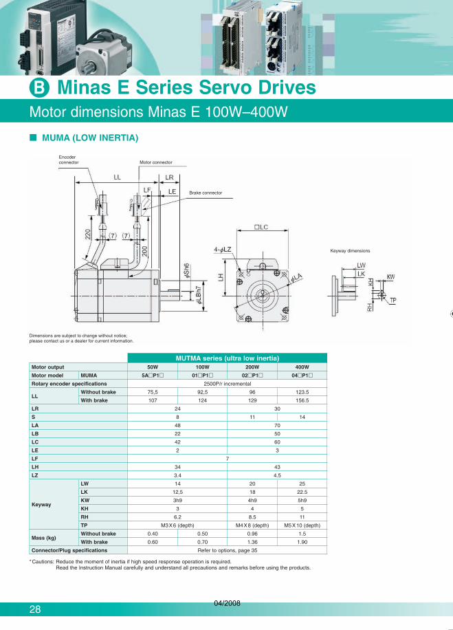
Motor dimensions Minas E 100W–400W
Minas E Series Servo Drives B
MUMA (LOW INERTIA)
Encoderconnector Motor connector
Dimensions are subject to change without notice; please contact us or a dealer for current information.
Brake connector
Keyway dimensions
MUTMA series (ultra low inertia)Motor output 50W 100W 200W 400W
Motor model MUMA 5A P1 01 P1 02 P1 04 P1
Rotary encoder specifications 2500P/r incremental
LLWithout brake 75,5 92,5 96 123.5
With brake 107 124 129 156.5
LR 24 30
S 8 11 14
LA 48 70
LB 22 50
LC 42 60
LE 2 3
LF 7
LH 34 43
LZ 3.4 4.5
Keyway
LW 14 20 25
LK 12,5 18 22.5
KW 3h9 4h9 5h9
KH 3 4 5
RH 6.2 8.5 11
TP M3X6 (depth) M4X8 (depth) M5X10 (depth)
Mass (kg)Without brake 0.40 0.50 0.96 1.5
With brake 0.60 0.70 1.36 1.90
Connector/Plug specifications Refer to options, page 35
*Cautions: Reduce the moment of inertia if high speed response operation is required.Read the Instruction Manual carefully and understand all precautions and remarks before using the products.
04/2008

29
Setup support software
C Software
SETUP SUPPORT SOFTWARE PANATERM® FOR MINAS SERIES AC SERVO MOTOR & DRIVER
BASIC FUNCTIONParameter setup
After a parameter has been defined on the screen, it will immediately be sent to the driver.
Once you register the parameters you frequently use, they can easily be set up on the screen.
Enter position data for Minas ACP drivers.
•
•
•
Graphic waveform display
Parameter
Monitor
PANATERM® assists users in setting parameters, monitoring control conditions, setup support and analysing mechanical operation data on the PC screen when installed in a commer-cially available personal computer and connected to the Minas series through the RS232C serial interface.
ANALYSIS OF MECHANICAL OPERATION DATAFrequency analysis
Measures frequency characteristics of the machine; displays Bode diagram.
Product number: DVOP4460
•
MONITORING CONTROL CONDITIONSMonitor
Control conditions: control mode, velocity, torque, error and warning.
Driver input signal.
Load conditions: total count of command/feedback pulses, load ratio, regenera-tive resistor load ratio.
Alarm
Displays the numbers and contents of the current alarm and a history of the last 14 error events.
Clears the numbers and contents of the current alarm and a history of the last 14 error events.
•
•
•
•
•
SETUPAuto tuning
Gain adjustment and inertia ratio measurement.
Graphic waveform display
The graphic display shows command velocity, actual velocity, torque, and error waveforms.
Absolute encoder setup
Clears absolute encoder at the origin.
Displays single revolution/multirevolution data.
Displays absolute encoder status.
•
•
•
•
•
04/2008

FFWD FWD DWELL REV
v
s
t
t
FF F
REV
30
20082008
PROGRAM, LADDER DIAGRAM BODY
Drilling setupTiming diagram
EXAMPLE FOR CONSECUTIVE MOVEMENT IN A DRILLING APPLICATION
See also: www.plcopen.org/MC_Certification/Panasonic/shortform_statement_Panasonic.htm
Motion Control Library for FPWIN Pro
SoftwareC
ADVANTAGES OF PLC PROGRAMS USING THE MOTION CONTROL LIBRARY COMPLIANT WITH THE PLCOPEN STANDARD:
Simple – Easy programming and installation, even for complex applications
Efficient – In the number of function blocks and in design and understanding
Consistent – Compliant with the IEC 61131-3 PLC programming standard
Universal – Hardware-independent
Flexible – Add hardware or expand range of applications at any time
Complete – Comprehensive product line solves typical positioning applications easily
•
•
•
•
•
•
Panasonic’s Motion Control Library is designed to save programming time with a sophisticated yet user-friendly software solution. Our library includes function blocks programed according to PLCopen’s speci-fications. Developed to simplify programming of FP2 and FP (Sigma) positioning units.
PLCopen, an independent international organization, aims to harmonize access across platforms during development, installation and maintenance based on the IEC61131-3 environment.
Administrative MotionSingle Axis Multiple Axis Single Axis Multiple Axis
MC_Power MC_CamTableSelect MC_MoveAbsolute MC_CamInMC_ReadStatus MC_MoveRelative MC_CamOutMC_ReadAxisError MC_MoveAdditive* MC_GearInMC_ReadParameter MC_MoveSuperimposed MC_GearOutMC_ReadBoolParameter MC_MoveVelocityMC_WriteParameter MC_HomeMC_WriteBoolParameter MC_StopMC_ReadActualPosition MC_PositionProfileMC_Reset MC_VelocityProfile
MC_AccelerationProfile
* If executed, the current motion is briefly interrupted due to hardware reasons.
Motion Control Library
Note: FP2 positioning unit multifunction type version 5.4 or newer usable with FP (Sigma) positioning unit
Product number NCL-MC-LIB D
04/2008

31
Configurator PM software tool for RTEX
C Software
TOOL OPERATIONS• Each axis can be operated by tool operation independently from the operation
modes (PROG and RUN) of the FP control unit (or the FP2CPU unit).
• JOG operation and teaching can be carried out easily to index positioning points. Test operation is possible without having to create a rudder program.
DATA MONITORData table no. during operation
Auxiliary output
Current position, speed and vector
Error code, warning code (Errors and warnings can also be cleared)
•
•
•
•
The Configurator PM provides powerful yet simple full support ranging from configuration settings and startup to opera-tion monitoring. This reduces the time and man hours required for system setup.
Axis settings
Check the axis to be used. Select axis no. used.
Grouping of axes for in-terpolation operations is carried out simply by dragging and dropping the relevant axes.
Parameter settings
The details of the settings can be displayed in a table. Details on how to create settings for each category are explained in the box below.
Parameters can be copied between axes. In instances where many settings are shared among the axes, this can reduce the number of repeat inputs.
Each axis (or each interpolation axis group) has a separate sheet, and data tables for each axis are displayed in an easy-to-understand manner.
Data tables can be exported as text files in CSV format.This is effective when making printouts for document management.
You can copy parts of a CSV file to a data table using Cut & Paste.
Data table creation
STATUS MONITORConnection status of each axis
Model code of each motor amp and motor connected
Servo lock status
Origin proximity input, limit input
•
•
•
•
Simple input as in Excel.
04/2008

XXXXXXXX
32
��
�37.3
Encoder cables
SoftwareC
MFECA0 0EAM
Encoder cables for Minas A4 and E servo drives, standard connectors, usable for drag chainProduct number Power range Minas A4 Power range Minas E Length L
MFECA0010EAM 50–750W 50–400W 1mMFECA0020EAM 50–750W 50–400W 2mMFECA0030EAM 50–750W 50–400W 3mMFECA0050EAM 50–750W 50–400W 5mMFECA0100EAM 50–750W 50–400W 10m
Encoder cable for Minas A4 servo drives, high quality connectors, IP67, usable for drag chain
Product number Power range Minas A4 Length LMFECA0020EAB 50–750W 2mMFECA0030EAB 50–750W 3mMFECA0040EAB 50–750W 4mMFECA0050EAB 50–750W 5mMFECA0070EAB 50–750W 7mMFECA0100EAB 50–750W 10mMFECA0150EAB 50–750W 15mMFECA0200EAB 50–750W 20m
Encoder cable for Minas A4 with 17-bit absolute encoder, standard connectors, without battery holder
Product number Power range Minas A4 Length LMFECA0030EAD 50–750W 3mMFECA0050EAD 50–750W 5mMFECA0100EAD 50–750W 10m
Encoder cable for Minas A4 with 17-bit absolute encoder, standard connectors, with battery holder
Product number Power range Minas A4 Length LMFECA0030EAE 50–750W 3mMFECA0050EAE 50–750W 5mMFECA0100EAE 50–750W 10m
Encoder cable for Minas A4 with incremental encoder, IP67 metal connectors, usable for drag chain
Product number Power range Minas A4 Length LMFECA0030ESD 1–5kW 3mMFECA0050ESD 1–5kW 5mMFECA0100ESD 1–5kW 10m
MFECA0 0EAB
MFECA0 0ESD
MFECA0 0EAD
MFECA0 0EAE
L
04/2008

XXXXXXXX
33
Motor and brake cables
Accessories
Motor cable for Minas A4 servo drives, usable for drag chainProduct number Power range Length L
MFMCA0010EED 50 – 750W 1m
MFMCA0020EED 50 – 750W 2m
MFMCA0030EED 50 – 750W 3m
MFMCA0050EED 50 – 750W 5m
MFMCA0100EED 50 – 750W 10m
Motor cable for Minas E servo drives, usable for drag chainProduct number Power range Length L
MFMCA0050AEB 50 – 400W 5m
MFMCA0100AEB 50 – 400W 10m
MFMCA0200AEB 50 – 400W 20m
Motor cable for Minas A4, high quality connectors, IP67, usable for drag chainProduct number Power range Length L
MFMCA0020EBD 50 – 750W 2m
MFMCA0030EBD 50 – 750W 3m
MFMCA0040EBD 50 – 750W 4m
MFMCA0050EBD 50 - 750W 5m
MFMCA0100EBD 50 – 750W 10m
MFMCA0150EBD 50 – 750W 15m
MFMCA0200EBD 50 – 750W 20m
Motor cable for Minas A4 motors with brake, high quality connectors, IP67, usable for drag chain
Product number Power range Length LMFMCA0020EBDB 50 – 750W 2m
MFMCA0030EBDB 50 – 750W 3m
MFMCA0050EBDB 50 – 750W 5m
MFMCA0070EBDB 50 – 750W 7m
MFMCA0100EBDB 50 – 750W 10m
Motor cable for Minas A4, without brake, usable for drag chainProduct number Power range Length L
MFMCD0032ECD 1 – 1.5kW 3m
MFMCD0052ECD 1 – 1.5kW 5m
MFMCD0102ECD 1 – 1.5kW 10m
Motor cable for Minas A4, without brake, usable for drag chainProduct number Power range Length L
MFMCD0032ECT 2kW 3m
MFMCD0052ECT 2kW 5m
MFMCD0102ECT 2kW 10m
MFMCD0152ECT 2kW 15m
Motor cable for Minas A4, without brake, usable for drag chainProduct number Power range Length L
MFMCA0033ECT 3–5kW 3m
MFMCA0053ECT 3–5kW 5m
MFMCA0103ECT 3–5kW 10m
Motor cable for Minas A4, with brake, usable for drag chainProduct number Power range Length L
MFMCA0032FCD 1–1.5kW 3m
MFMCA0052FCD 1–1.5kW 5m
MFMCA0102FCD 1–1.5kW 10m
Motor cable for Minas A4, with brake, usable for drag chainProduct number Power range Length L
MFMCA0032FCT 2kW 3m
MFMCA0052FCT 2kW 5m
MFMCA0102FCT 2kW 10m
Motor cable for Minas A4, with brake, usable for drag chainProduct number Power range Length L
MFMCA0033FCT 3–5kW 3m
MFMCA0053FCT 3–5kW 5m
MFMCA0103FCT 3–5kW 10m
Brake junction cable for Minas A 4 and E motors with brake, usable for drag chainProduct number Power range Minas A Power range Minas E Length L
MFMCB0030GET 50 – 750W 50 – 400W 3m
MFMCB0050GET 50 – 750W 50 – 400W 5m
MFMCB0100GET 50 – 750W 50 – 400W 10m
(50) (50)�
(�11)
(10.0)
(12.0)
(4) (4)
MFMCA0 0EED
MFMCA0 0EBD
(50)�
(�12.5)
�37.3
MFMCD0 2ECD MFMCD0 2ECT
� (50)
�
(50)
(�12.5)
�37.3
(��.8)
MFMCA0 2FCD
MFMCA0 2FCT
(��.8)
(40) (50)�
(5.6)
(12.0)
(10.0) V
MFMCB0 0GET
MFMCA0 0AEB
MFMCA0 0EBDB
04/2008

XXXXXXXX
34
Direct connection cables to FP (Sigma) and FP2
Accessories
Product number Description Number of axes Power range Length Connectors
DVOP0980W-1 FP (Sigma) NPN to CN I/F 1 0.05–5kW 1m 50 pin Molex to 2x10 pin MIL
DVOP0981W-1 FP (Sigma) NPN to CN I/F 2 0.05–5kW 1m 2x50 pin Molex to 3x10 pin MIL
DVOP0982W-1 FP (Sigma) PNP to CN I/F 1 0.05–5kW 1m 50 pin Molex to 2x10 pin MIL
DVOP0983W-1 FP (Sigma) PNP to CN I/F 2 0.05–5kW 1m 2x50 pin Molex to 3x10 pin MIL
DVOP0984W-1 FP (Sigma) NPN to CN I/F, with TLC-signal 2 0.05–5kW 1m 50 pin Molex to 2x10 pin MIL, with TLC-signal
DVOP0985W-1 FP (Sigma) / FP2 Positioning units transistor type 2 0.05–5kW 1m 50 pin Molex to 1x40 pin MIL
DVOP0986W-1 FP (Sigma) / FP2 Positioning units line driver type 2 0.05–5kW 1m 50 pin Molex to 1x40 pin MIL
In/out connectors for the PLC FP (Sigma). Unused inputs/outputs can be used for other purposes.
DVOP0980W-1
DVOP0982W-1
DVOP0983W-1
DVOP0984W-1
DVOP0981W-1
For pulse control, not for Minas A4N / RTEX
DVOP0985W-1DVOP0986W-1
DIRECT CONNECTION TO FP (SIGMA) AND FP2 POSITIONING UNITS(Not for Minas A4N/ RTEX transistor or line driver types)
For FP (Sigma) CPU PNP or NPNOne axis
Two axes
Two axes
04/2008

XXXXXXXX
35
Other cables, connectors, brake resistors, filters
Accessories
gnal
a). ther
Product number Description
DVOP1960 RS232C communication cable to PC9 pin Sub-D
DVOP1972 RS485 communication cable Mini-DIN 8Pin-MD connector, 1m
CONNECTOR UNITSProduct number Description
DVOP3670 Connector kit for motor and encoder
DVOP4310 Connector kit for Minas A4 servo drives 1 to 2kW, without brake
DVOP4320 Connector kit for Minas A4 servo drives 3 to 5kW, without brake
DVOP4330 Connector kit for Minas A4 servo drives 1 to 2kW, with brake
DVOP4340 Connector kit for Minas A4 servo drives 3 to 5kW, with brake
DVOP4350 Connector for Minas A4 drivers for external equipment
DVOP4380 Connector kit for Minas A4 servo for encoder- and motor connection
FILTERSProduct number Description
FN2060-6-06 EMC filter for control circle, Minas A4 servo drives 1 to 2kW
FN2090-10-06 Multi-stage EMI filter, 1-phase, for Minas A4/N servo driver MDDT5540, 1 to 1.5kW
FN2410-32-33 Multi-stage EMI filter, 1-phase, for Minas A4/N servo driver 2 to 5kW
FS21238-6-07 FS21238-6-07 EMC filter for Minas A4 servo drives 50 to 750W
DVOP4160 EMC filter for Minas E
BRAKE RESISTORSProduct number Power range Additional
information / description
BWD250100 30–750W 100 Ohm/100W
BWD600027 1–5kW 27 Ohm/240W
MANUALSProduct number Additional information / description
DVOP4210 Minas A4-series manual
DVOP4490 Minas A4P-series manual
DVOP3700 Minas E-series manual
Minas A4N manual is only available as PDF file from panasonic-electric-works.com
OTHER ACCESSORIESProduct number Description
DVOP2990 Lithium battery for absolute encoder, Minas A4, 3.6V 2000mAh
DVOP37300 Cable set (3m) interface, encoder and motor cable and connector kit of drive power
DVOP3811 DIN rail mounting kit for Minas E drivers
DVOP39200 Cable set (5m) interface, encoder and motor cable and connector kit of drive power
DVOP4420 Operating Console for Minas A4 and E servo drivers
DVOP4460 PANATERM Software for Minas servo drives, CD-ROM
COMMUNICATION CABLES
INTERFACE CABLESProduct number Description
DVOP0800 Interface cable for Minas E driver 26 pins
DVOP4360 Interface Connector cable for Minas A4 drivers, length 2m
DVOP4510 I/O Interface cable for Minas A4N and A4P servo drivers, length 2m
04/2008

Panasonic Electric Works
Please contact our Global Sales Companies in:Europe
Headquarters Panasonic Electric Works Europe AG Rudolf-Diesel-Ring 2, 83607 Holzkirchen, Tel. (08024) 648-0, Fax (08024) 648-111, www.panasonic-electric-works.comAustria Panasonic Electric Works Austria GmbH
PEW Electronic Materials Europe GmbHRep. of PEWDE, Josef Madersperger Str. 2, 2362 Biedermannsdorf, Tel. (02236) 26846, Fax (02236) 46133, www.panasonic-electric-works.atEnnshafenstraße 9, 4470 Enns, Tel. (07223) 883, Fax (07223) 88333, www.panasonic-electronic-materials.com
Benelux Panasonic Electric WorksSales Western Europe B.V.
De Rijn 4, (Postbus 211), 5684 PJ Best, (5680 AE Best), Netherlands, Tel. (0499) 372727, Fax (0499) 372185, www.panasonic-electric-works.nl
Czech Republic Panasonic Electric Works Czech s.r.o. Prumyslová 1, 34815 Planá, Tel. 374 799 990, Fax 374 799 999, www.panasonic-electric-works.czFrance Panasonic Electric Works
Sales Western Europe B.V.French Branch Office, B.P. 44, 91371 Verrières le Buisson CEDEX, Tél. 01 60135757, Fax 01 60135758, www.panasonic-electric-works.fr
Germany Panasonic Electric Works Deutschland GmbH Rudolf-Diesel-Ring 2, 83607 Holzkirchen, Tel. (08024) 648-0, Fax (08024) 648-555, www.panasonic-electric-works.deHungary Panasonic Electric Works Europe AG Magyarországi Közvetlen Kereskedelmi Képviselet, 1117 Budapest, Neumann János u. 1., Tel. 06 1 482 9258, Fax 06 1 482 9259,
www.panasonic-electric-works.huIreland Panasonic Electric Works UK Ltd. Dublin, Tel. (01) 4600969, Fax (01) 4601131, www.panasonic-electric-works.co.ukItaly Panasonic Electric Works Italia s.r.l. Via del Commercio 3-5 (Z.I. Ferlina), 37012 Bussolengo (VR), Tel. (045) 6752711, Fax (045) 6700444, www.panasonic-electric-works.it
PEW Building Materials Europe s.r.l. Piazza della Repubblica 24, 20154 Milano (MI), Tel. (02) 29005391, Fax (02) 29003466, www.panasonic-building-materials.comNordic Countries Panasonic Electric Works Nordic AB
PEW Fire&Security Technology Europe ABSjöängsvägen 10, 19272 Sollentuna, Sweden, Tel. (08) 59476680, Fax (08) 59476690, www.panasonic-electric-works.seCitadellsvägen 23, 21118 Malmö, Tel. (040) 6977000, Fax (040) 6977099, www.panasonic-fire-security.com
Poland Panasonic Electric Works Europe AG Przedstawicielstwo w Polsce, Al. Krakowska 4/6, 02-284 Warszawa, Tel. 22 338-11-33, Fax 22 338-12-00, www.panasonic-electric-works.plPortugal Panasonic Electric Works España S.A. Portuguese Branch Office, Avda Adelino Amaro da Costa 728 R/C J, 2750-277 Cascais, Tel. (21) 4812520, Fax (21) 4812529Spain Panasonic Electric Works España S.A. Barajas Park, San Severo 20, 28042 Madrid, Tel. (91) 3293875, Fax (91) 3292976, www.panasonic-electric-works.esSwitzerland Panasonic Electric Works Schweiz AG Grundstrasse 8, 6343 Rotkreuz, Tel. (041) 7997050, Fax (041) 7997055, www.panasonic-electric-works.chUnited Kingdom Panasonic Electric Works UK Ltd. Sunrise Parkway, Linford Wood, Milton Keynes, MK14 6 LF, Tel. (01908) 231555, Fax (01908) 231599, www.panasonic-electric-works.co.uk
North & South America
USA PEW Corporation of America 629 Central Avenue, New Providence, N.J. 07974, Tel. 1-908-464-3550, Fax 1-908-464-8513, www.pewa.panasonic.com
Asia Pacific /China / Japan
China Panasonic Electric Works (China) Co., Ltd. Level 2, Tower W3, The Towers Oriental Plaza, No. 2, East Chang An Ave., Dong Cheng District, Beijing 100738, Tel. (010) 8518-5988, Fax (010) 8518-1297
Hong Kong Panasonic Electric Works(Hong Kong) Co., Ltd.
RM1205-9, 12/F, Tower 2, The Gateway, 25 Canton Road, Tsimshatsui, Kowloon, Hong Kong, Tel. (0852) 2956-3118, Fax (0852) 2956-0398
Japan Matsushita Electric Works, Ltd. 1048 Kadoma, Kadoma-shi, Osaka 571-8686, Japan, Tel. (06) 6908-1050, Fax (06) 6908-5781, www.mew.co.jp/e-acg/Singapore Panasonic Electric Works Asia Pacific Pte. Ltd. 101 Thomson Road, #25-03/05, United Square, Singapore 307591, Tel. (06255) 5473, Fax (06253) 5689
Copyright © 2008 • Printed in Germany4152 euen 04/08
Asia Pacific China JapanNorth America Europe
Global Network
04/2008