motion compensation based video coder
TRANSCRIPT

7/30/2019 Motion Compensation based Video Coder
http://slidepdf.com/reader/full/motion-compensation-based-video-coder 1/72

7/30/2019 Motion Compensation based Video Coder
http://slidepdf.com/reader/full/motion-compensation-based-video-coder 2/72
II
Information Engineering and Technology Faculty
German University in Cairo
Motion Compensation Based video
coder on a DSP board
Bachelor Thesis
Author: Mohamed Ismail Mohamed
Supervisor: Dr.Gamal Fahmy
Submission Date: 13 July, 2009

7/30/2019 Motion Compensation based Video Coder
http://slidepdf.com/reader/full/motion-compensation-based-video-coder 3/72
III
This is to certify that:
(i) The thesis comprises only my original work towards the Bachelor Degree
(ii) Due acknowledgement has been made in the text to all other material used
Mohamed Ismail Mohamed
13 July , 2009

7/30/2019 Motion Compensation based Video Coder
http://slidepdf.com/reader/full/motion-compensation-based-video-coder 4/72
IV
Abstract
The goal in video compression is to remove the redundancy in a video sequence while preserving its
fidelity. Video sequence experiences both temporal and spatial redundancies, „temporal‟ due to
correlation between consecutive frames in the sequence and spatial due to correlation between
neighboring elements inside each frame. Motion estimation/compensation is used to predict frame for the
issue of temporal redundancy, while transform coding as discrete cosine transform is used to remove
spatial redundancy in visual data. Consequently, encoder uses fewer bits allowing a more efficient
transmission and storage of the visual data.
This thesis has two major purposes: (1) to design a hybrid motion compensated discrete cosine transform
video coder based on the block matching algorithm. (2) is to investigate the effect of changing some of
video coding parameters and strategies on the reconstructed video‟s visual quality and also on the coder
complexity. Three video sequences were involved in the empirical part, videos contain different scenes
with various specifications to demonstrate the results and to highlight the difference between each of the
reconstructed sequence‟s quality to the change of coding parameters. Analysis showed that using a
smaller block of the frame to search for in the reference frame will always result in better quality,
however this will also require dividing the frame into more blocks and will be more complex. Results also
proved that searching in a larger region in the reference frame for a specific block, will give a better
chance finding the best matching block. Furthermore, results illustrated the exceptions for the non
improved quality for low motion videos when increasing the search region. In addition this thesis
explores three different search strategies and distinguishes between each one‟s performance. Finally,
testing the full coder took place, including the discrete cosine transform applied to frames that are
unpredicted to minimize their encoded bits and to notice the effect on the reconstructed sequences quality.

7/30/2019 Motion Compensation based Video Coder
http://slidepdf.com/reader/full/motion-compensation-based-video-coder 5/72
V
Dedication
To my Parents, Ismail Hafez and Safaa Moghazy
I am grateful to my supervisor Dr.Gamal Fahmy for all the support during the process.

7/30/2019 Motion Compensation based Video Coder
http://slidepdf.com/reader/full/motion-compensation-based-video-coder 6/72
VI
Contents
Chapter 1 Introduction ....................................................................................... 1
1.1 Importance of Video Compression .................................................................................................. 1
1.2 Objective .......................................................................................................................................... 2
1.3 Methodology .................................................................................................................................... 3
1.4 Thesis Organization ......................................................................................................................... 4
Chapter 2 Background ........................................................................................ 5
2.1 Digital Video .................................................................................................................................... 6
2.2 Objective Video Quality .................................................................................................................. 7
2.3 Color Spaces .................................................................................................................................... 7
2.3.1 RGB...................................................................................................................................... 8
2.3.2 YCbCr .................................................................................................................................. 8
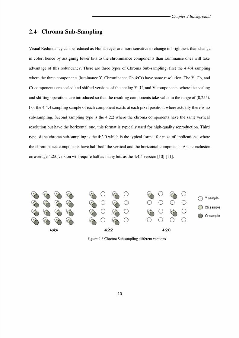
2.4 Chroma Sub-Sampling ................................................................................................................... 10
2.5 Digital Video Formats and Applications......................................................................................... 11
Chapter 3 Video Compression Fundamentals ................................................ 13
3.1 Video Coding Standards ................................................................................................................ 14
3.2 MPEG-2 Coding Standard ............................................................................................................. 16
3.2.1 Group of Pictures............................................................................................................... 18
3.3 Motion Estimation and Compensation ........................................................................................... 19

7/30/2019 Motion Compensation based Video Coder
http://slidepdf.com/reader/full/motion-compensation-based-video-coder 7/72

7/30/2019 Motion Compensation based Video Coder
http://slidepdf.com/reader/full/motion-compensation-based-video-coder 8/72
VIII
List of Figure
Figure 1.1 A Typical Video Encoder ............................................................................................................... 4
Figure 2.1 Example for an image along with its RGB components .............................................................. 8
Figure 2.2 Example for an image along with its YCbCr components........................................................... 9
Figure 2.3 Chroma Subsampling different versions .................................................................................... 10
Figure 3.1 MPEG Group of pictures ............................................................................................................ 18
Figure 3.2 Video codec with prediction ...................................................................................................... 19
Figure 3.3 Video codec with motion estimation and compensation .......................................................... 20
Figure 4.1 Block matching process.............................................................................................................. 22
Figure 4.2 Full search ‘Raster’ and ‘Spiral’ algorithms ................................................................................ 24
Figure 4.3 Fast search ‘Logarithmic’ algorithm ........................................................................................... 26
Figure 5.1 2-D DCT performed on an 8x8 block of an image ..................................................................... 28
Figure 5.2 An image with the intensity map along with the compacted version ....................................... 29
Figure 5.3 Inverse DCT of Trees; (a) DCT(100%); (b) DCT(75%); (c) DCT(50%); (d) DCT(25%). ................... 30
Figure 6.1 Image for BF561 Hardware ........................................................................................................ 31
Figure 6.2 Connector Locations .................................................................................................................. 32
Figure 6.3 Visual DSP++ Release 5.0 ........................................................................................................... 34
Figure 6.4 Connection to Video In and Video Out devices ......................................................................... 36
Figure 7.1 PSNR for {p} and {B} predicted frames using „Logarithmic search‟ ....................................... 41
Figure 7.2 PSNR for {p} and {B} predicted frames using „Raster full search‟ .......................................... 42
Figure 7.3 PSNR for {p} and {B} predicted frames using „Spiral full search‟ ........................................... 42

7/30/2019 Motion Compensation based Video Coder
http://slidepdf.com/reader/full/motion-compensation-based-video-coder 9/72
IX
Figure 7.4 PSNR for predicted frames “Foreman video” using „Raster full search‟ different search
window size ............................................................................................................................. 43
Figure 7.5 PSNR for {p} and {B} predicted "Stephan video" frames using 'Logarithmic search‟ ............. 44
Figure 7.6 PSNR for {p} and {B} predicted "Stephan video" frames 'Full search algorithms‟.................. 44
Figure 7.7 PSNR for {p} and {B} predicted "Stephan video" frames for different search windows 'Raster
full search algorithm‟ ................................................................................................................ 45
Figure 7.8 PS NR for {p} and {B} predicted "Fish video" frames using 'Logarithmic fast search algorithm‟
.................................................................................................................................................. 46
Figure 7.9 PSNR for {P} and {B} predicted “Fish video” frames using „Raster full search algorithm‟ .... 46
Figure 7.10 PSNR for {p} and {B} predicted "Fish video" frames different search windows using 'Raster
full search algorithm‟ .............................................................................................................. 47
Figure 7.11 Foreman video predicted frames macroblock size 1 "Logarithmic search" ............................ 48
Figure 7.12 Foreman video predicted frames macroblock size 8 "Logarithmic search" ............................ 48
Figure 7.13 Foreman video predicted frames macroblock size 16 "Logarithmic search" .......................... 48
Figure 7.14 Stephan video predicted frames macroblock size 1 "Logarithmic search" ............................. 48
Figure 7.15 Stephan video predicted frames macroblock size 8 "Logarithmic search" ............................. 48
Figure 7.16 Stephan video predicted frames macroblock size 16 "Logarithmic search" ........................... 48
Figure 7.17 Fish video predicted frames macroblock size 1 "Logarithmic search" .................................... 48
Figure 7.18 Fish video predicted frames macroblock size 8 "Logarithmic search" .................................... 48
Figure 7.19 Fish video predicted frames macroblock size 16 "Logarithmic search" .................................. 48
Figure 7.20 Foreman video predicted frames macroblock size 1 "Raster search" ..................................... 48
Figure 7.21 Foreman video predicted frames macroblock size 8 "Raster search" ..................................... 48
Figure 7.22 Foreman video predicted frames macroblock size 16 "Raster search" ................................... 48
Figure 7.23 Stephan video predicted frames macroblock size 1 "Raster search" ...................................... 48

7/30/2019 Motion Compensation based Video Coder
http://slidepdf.com/reader/full/motion-compensation-based-video-coder 10/72
X
Figure 7.24 Stephan video predicted frames macroblock size 8 "Raster search" ...................................... 48
Figure 7.25 Stephan video predicted frames macroblock size 16 "Raster search" .................................... 48
Figure 7.26 Fish video predicted frames macroblock size 1 "Raster search" ............................................. 48
Figure 7.27 Fish video predicted frames macroblock size 8 "Raster search" ............................................. 48
Figure 7.28 Fish video predicted frames macroblock size 16 "Raster search" ........................................... 48
Figure 7.29 PSNR values for "Foreman video" with search window 7 using 'Raster full search' ............... 48
Figure 7.30 PSNR values for "Foreman video" with search window 15 using 'Raster full search' ............. 48
Figure 7.31 PSNR values for "Foreman video" with search window 25 using 'Raster full search' ............. 48
Figure 7.32 PSNR values for "Stephan video" with search window 7 using 'Raster full search'................. 48
Figure 7.33 PSNR values for "Stephan video" with search window 15 using 'Raster full search' .............. 48
Figure 7.34 PSNR values for "Stephan video" with search window 25 using 'Raster full search' .............. 48
Figure 7.35 PSNR values for "Fish video" with search window 7 using 'Raster full search' ...................... 48
Figure 7.36 PSNR values for "Fish video" with search window 15 using 'Raster full search' ..................... 48
Figure 7.37 PSNR values for "Fish video" with search window 25 using 'Raster full search' ..................... 48
Figure 7.38 PSNR for predicted frames using different 2D-DCT Compression Qualities ............................ 48
Figure 7.39 foreman video predicted frames "NO DCT" ............................................................................ 48
Figure 7.40 foreman video predicted frames "DCT 36:64"......................................................................... 48
Figure 7.41 foreman video predicted frames "DCT 21:64"......................................................................... 48
Figure 7.42 foreman video predicted frames "DCT 10:64"......................................................................... 48
Figure 7.43 foreman video predicted frames "DCT 1:64" ........................................................................... 48
Figure 8.1 Block diagram for Search window size decision after motion is detected ................................ 48

7/30/2019 Motion Compensation based Video Coder
http://slidepdf.com/reader/full/motion-compensation-based-video-coder 11/72
XI
List of Tables
Table 2.1 Video formats with each format specifications………...………………………………………13
Table 3.1 Digital video formats with no. of frames per second and bit rate ………...……………………15

7/30/2019 Motion Compensation based Video Coder
http://slidepdf.com/reader/full/motion-compensation-based-video-coder 12/72
XII
Abbreviations
ADSL Asymmetric Digital Subscriber Line
AVC Advanced Video Coding
B-frame Bi-directionally predicted frame
BDS Block Distortion Surface
BMA Block Matching Algorithm
CIF Common Intermediate Format
CMY Cyan, Magenta, Yellow
CMYK Cyan, Magenta, Yellow, Black
DCT Discrete Cosine Transform
DPCM Differential Pulse Code Modulation
DVD Digital Versatile Disk
GOP Group of Pictures
HDTV High Definition Television
I-frame Intra-coded frame
IDCT Inverse Discrete Cosine Transform
ISDN Integrated Services Digital Network
ISO International Organization for Standardization
ITU International Telecommunication Union
JPEG Joint Photographic Experts Group
7/30/2019 Motion Compensation based Video Coder
http://slidepdf.com/reader/full/motion-compensation-based-video-coder 13/72
XIII
MAE Mean Absolute Error
MC Motion Compensation
ME Motion Estimation
MSE Mean Squared Error
MPEG Moving Pictures Expert Group
NTSC National Television System Committee
P-frame Predictive frame
PAL Phase Alternating Line
PSNR Peak Signal to Noise Ratio
QCIF Quarter Common Intermediate Format
RGB Red, Green, Blue
SAE Sum of Absolute Errors
SIF Source Intermediate Format
SDTV Standard Definition Television
UMTS Universal Mobile Telecommunications System
VDSL Very High Speed Subscriber Line
YCbCr Luminance, Chrominance blue, Chrominance red

7/30/2019 Motion Compensation based Video Coder
http://slidepdf.com/reader/full/motion-compensation-based-video-coder 14/72
Chapter 1 Introduction
1
Chapter One
1. Introduction
1.1 Importance of video compression
Video communication is a rapidly evolving field for several applications which include video telephony,
videoconference, remote surveillance, remote working and learning, etc. It is also a key feature for the
upcoming information and communication technologies based on residential digital lines (VDSL, ADSL
and ISDN) and the 3rd generation of mobile telephony system (UMTS). In this scenario, video image
compression plays a fundamental role in reducing the enormous bit-rate for transmission and storage. For
example a high quality HDTV picture which has spatial resolution 1920 x 1080 square pixels and
digitized as 8-bit per pixel, its uncompressed bit rate is about 1.3905G bit/sec. Consider also the Common
Intermediate Format (CIF), the standard for video conferencing that has spatial resolution 352x288. At 30
picture per second video signal and 8 bits per pixel, the uncompressed bit rate is about 36.5M bit/sec.
Even for smaller format, the Quarter CIF (QCIF) the uncompressed bit rate is about 9.1M bit/sec. ISDN
channel for example has only 64k bit/sec, which means that without compression, it is impossible or non
realistic to transmit over network or store such high-volume video data[1] [2]. To this objective, the ISO
and the ITU-T committees have worked on several compression standards such as JPEG, MPEG

7/30/2019 Motion Compensation based Video Coder
http://slidepdf.com/reader/full/motion-compensation-based-video-coder 15/72

7/30/2019 Motion Compensation based Video Coder
http://slidepdf.com/reader/full/motion-compensation-based-video-coder 16/72
Chapter 1 Introduction
3
1.3 Methodology
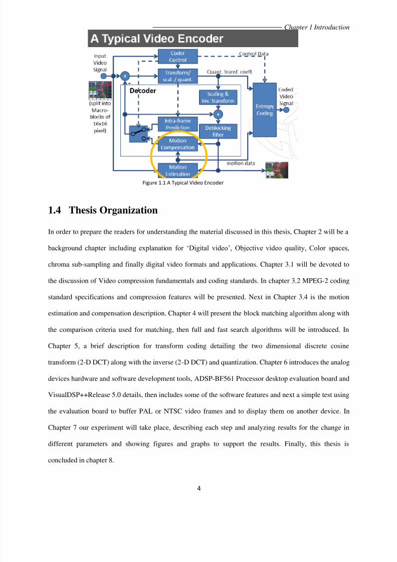
A typical encoder shown in figure 1.1 has an input video signal as a sequence of pictures, first these
pictures are processed one by one, divided into equal sized non-overlapping rectangular blocks ‘Macro-
blocks’ of on average 16x16 pixel. Ideally the frame dimensions are multiples of the block size and
square blocks are most common. If the ‘frame’ is one that will be used as reference to other frames
„intraframe‟, then it will be coded without any reference to others and will pass through the transform
coding and quantization block and then transmitted to the receiver. Otherwise if it is an „interframe‟ then
it will pass through the motion estimation and compensation blocks, where block matching algorithms
take place to search the reference frame for the best match and specify its location to create motion
vectors to point to this location.
Block size affects the performance of compression techniques. The larger the block size, the fewer the
number of blocks for each frame, and hence fewer motion vectors need to be transmitted. However,
borders of moving objects do not normally coincide with the borders of blocks and so larger blocks
require more correction data to be transmitted. Small blocks result in a greater number of motion vectors,
but each matching block is more likely to closely match its target and so less correction data is required.
Thus block size represents a tradeoff between minimizing the number of motion vectors and maximizing
the quality of the matching blocks. The relationship between block size, image quality, and compression
ratio has been the subject of much research and is well understood. Also the searching region ‘Search
Window’ (i.e. Number of candidate blocks to search) in the reference frame is represents a tradeoff
between finding the best match, hence better quality and exhaustive computations and waste of time [5].
7/30/2019 Motion Compensation based Video Coder
http://slidepdf.com/reader/full/motion-compensation-based-video-coder 17/72

7/30/2019 Motion Compensation based Video Coder
http://slidepdf.com/reader/full/motion-compensation-based-video-coder 18/72
Chapter 2 Background
5
Chapter Two
2. Background
Video (In Latin: “I see”), is a sequence of images referred to as “frames” and the number of still pictures
per unit of time of video is called the frame rate , Obviously the increase in the frame rate comes with
increase in the observed video quality, many standards specify on average 25 to 30 frames/sec. The main
point is that the frame rate must exceed 15 frames per sec to achieve the illusion of moving image.
A visual scene is continuous both spatially and temporally. In order to represent and process a visual
scene digitally it is necessary to sample the real scene spatially (typically on a rectangular grid” frame” in
the video image plan) and also temporally (typically as a series of still frames sampled at regular intervals
of time). Each frame element is known as pixel is represented digitally as one or more numbers that
describe the brightness and color of the sample [6].
7/30/2019 Motion Compensation based Video Coder
http://slidepdf.com/reader/full/motion-compensation-based-video-coder 19/72
Chapter 2 Background
6
2.1 Digital Video
‘Digital video’ refers to the capturing, manipulation and storage of video in digital formats, obtaining
digital video is done using two way (1) Directly from Digital cameras. (2) Conversion of an analog video
signal using both “Sampling and Quantization”. Video in digital domain is characterized by more than
one property, or in other words is preferable compared to analog video; Digital video is less subjective to
noise, higher visual quality than analog, allows advanced editing and processing, allows repeated
reproduction without losses and finally the most important feature, it allows better compression and
encryption schemes. Before examining methods for compressing and transporting digital video, it is
necessary to establish the concepts for video in digital domain [7]. Digital video is visual information
represented in a discrete form, suitable for digital electronic storage or transmission. In this part concepts
of digital video will be described such as: Color spaces (RGB and YCrCb) and Measuring and qualifying
visual quality. Video frames are formed using tri-chromatic color mixing theory which states that any
color can be formed by mixing three primary colors (RED, GREEN, BLUE) with the right proportion,
Also that is the way color monitors works, by exciting primary color phosphors using separate electronic
guns. Reflecting sources “Secondary colors” are cyan, magenta, yellow (CMY) these colors are used to
operate the color printers, but sometimes black (K) is added to these colors the enhance quality of printing
which results in the (CMYK) model.

7/30/2019 Motion Compensation based Video Coder
http://slidepdf.com/reader/full/motion-compensation-based-video-coder 20/72

7/30/2019 Motion Compensation based Video Coder
http://slidepdf.com/reader/full/motion-compensation-based-video-coder 21/72
Chapter 2 Background
8
as color spaces. Two of the most common color spaces are: RGB (red/green/blue) and YCrCb
(luminance/red chrominance/blue chrominance).
2.3.1 RGB
In the red/green/blue color space, each pixel is represented by three numbers indicating the relative
proportion of red, green and blue. Because the three components have equal importance to the final color,
RGB systems usually represent each component with the same precision and therefore the same number
of bits. Using 8 bits per component is quite common: 3 × 8 = 24
are required to represent each
pixel. Figure (2.1), shows an RGB image, along with its separate R, G and B components; Note that the
white snow consists of strong red, green, and blue; the brown barn is composed of strong red and green
with little blue; the dark green grass consists of strong green with little red or blue; and the light blue sky
is composed of strong blue and moderately strong red and green [6] [8].
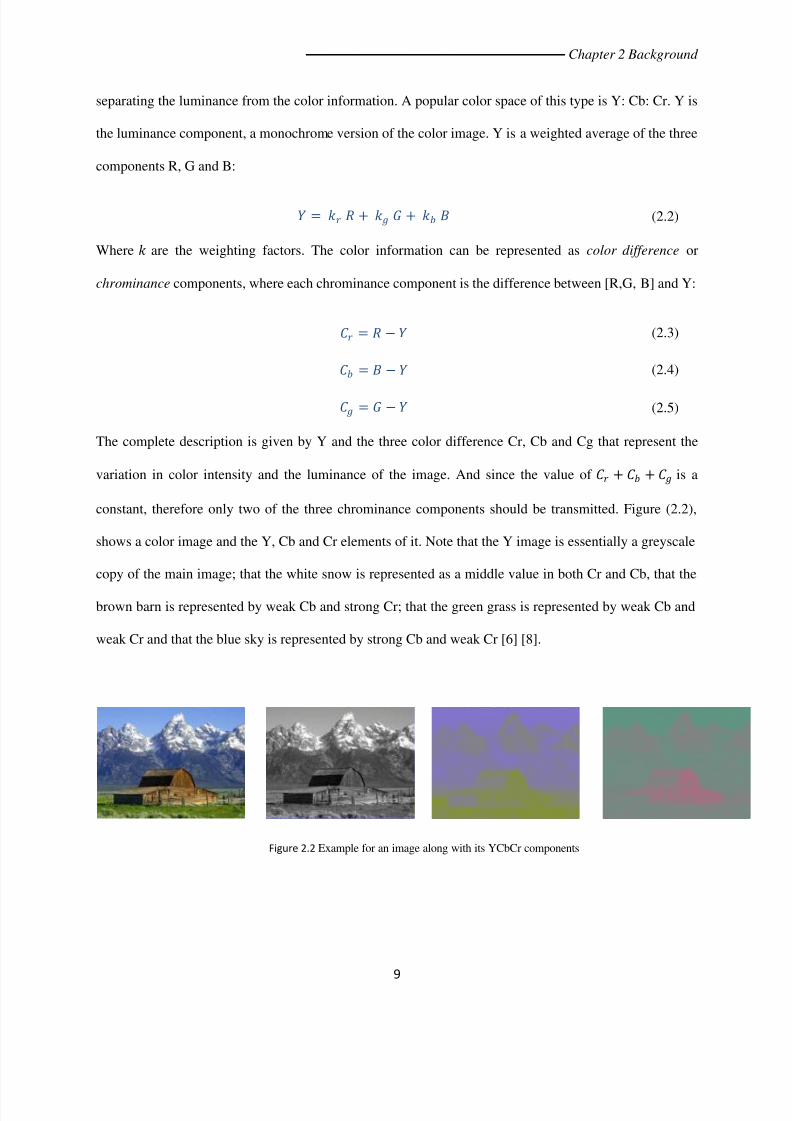
2.3.2 YCbCr
The human visual system is less sensitive to color than to luminance (brightness), however the RGB
system does not take advantage of this since the three colors are equally important and the luminance is
present in all the three color components. It is possible to represent the color image more efficiently by
Figure 2.1 Example for an image along with its RGB components
7/30/2019 Motion Compensation based Video Coder
http://slidepdf.com/reader/full/motion-compensation-based-video-coder 22/72
Chapter 2 Background
9
separating the luminance from the color information. A popular color space of this type is Y: Cb: Cr. Y is
the luminance component, a monochrome version of the color image. Y is a weighted average of the three
components R, G and B:
= + + (2.2)
Where are the weighting factors. The color information can be represented as color difference or
chrominance components, where each chrominance component is the difference between [R,G, B] and Y:
= − (2.3)
= − (2.4)
= − (2.5)
The complete description is given by Y and the three color difference Cr, Cb and Cg that represent the
variation in color intensity and the luminance of the image. And since the value of + + is a
constant, therefore only two of the three chrominance components should be transmitted. Figure (2.2),
shows a color image and the Y, Cb and Cr elements of it. Note that the Y image is essentially a greyscale
copy of the main image; that the white snow is represented as a middle value in both Cr and Cb, that the
brown barn is represented by weak Cb and strong Cr; that the green grass is represented by weak Cb and
weak Cr and that the blue sky is represented by strong Cb and weak Cr [6] [8].
Figure 2.2 Example for an image along with its YCbCr components
7/30/2019 Motion Compensation based Video Coder
http://slidepdf.com/reader/full/motion-compensation-based-video-coder 23/72

7/30/2019 Motion Compensation based Video Coder
http://slidepdf.com/reader/full/motion-compensation-based-video-coder 24/72
Chapter 2 Background
11
2.5 Digital Video Formats and Applications:
Many digital video formats are being used nowadays for example the CIF (Common intermediate format )
which has a size of 352x288 and is color sampled by the 4:2:0 technique, CIF uses 30 frames per second
and its raw data is 37 Mbps which can be compressed to about 128-384 Kbps, CIF is used for Video
conferencing over ISDN/internet. While QCIF is a quarter of CIF with size of 176x144 and also uses
4:2:0 color sampling and 30 frames per second, on the other hand its raw data is 9 Mbps and can be
compressed to about 64-128 Kbps and QCIF is used for Video telephony over wired/wireless modems.
The new H.263 video codec standard which is better than the H.261 and which can compress the QCIF to
about 20 Kbps with better quality than the H.261.
The SIF (Source Intermediate Format) size is 352x240 for the 30 frames per second technique and
352x288 for the 25 frames per second technique. And as well SIF uses 4:2:0, with a raw data of 30 Mbps.
This format is targeted for video applications which require medium quality such as video games and CD
movies. SIF is compressed using the MPEG-1 ( Motion Picture Expert Group) technique to 1.1 Mbps, SIF
is used for intermediate quality video distribution VCD.
Table 2.1 Video formats with each format specifications
Video format Size Color sampling Frame rate Raw data (Mbps)
SIF 352x240/288 4:2:0 30/25 fps 30
CIF 352x288 4:2:0 30 fps 36.5
QCIF 176x144 4:2:0 30 fps 9.1

7/30/2019 Motion Compensation based Video Coder
http://slidepdf.com/reader/full/motion-compensation-based-video-coder 25/72
Chapter 2 Background
12
The Last decade has seen a rapid increase in applications for digital video technology and new, innovative
applications continue to emerge, such as; Video Conferencing, video telephony, Remote learning, Remote
medicine, Games and entertainment [6] [8] [11].

7/30/2019 Motion Compensation based Video Coder
http://slidepdf.com/reader/full/motion-compensation-based-video-coder 26/72
13
Chapter 3 Video Compression Fundamentals
Chapter Three
3. Video Compression
Fundamentals
Video represented in a digital form requires large number of bits, volume of data for this representation is
too large for most of storage and transmission systems which exceeds the continual increase in storage
capacity and transmission bandwidth. Table (2) shows the uncompressed bit rates of several video
formats. From this table it can be seen that even the QCIF at 15 frames per second (Low quality video)
requires 4.6Mbps for transmission or storage.
Table 3.1 Digital video formats with no. of frames per second and bit rate
Format Frames per second Bit rate (uncompressed)
ITU-R 601 30 fps 216Mbps
CIF 30 fps 36.5Mbps
QCIF 15 fps 4.6Mbps

7/30/2019 Motion Compensation based Video Coder
http://slidepdf.com/reader/full/motion-compensation-based-video-coder 27/72
14
Chapter 3 Video Compression Fundamentals
Now it is clear that there is a reason for presence of video compression, due to that large gap between
high bit rate for uncompressed video data and the available capacity of transmission and storage systems.
Video compression systems aim to reduce the amount of data required to store or transmit videos while
maintaining an acceptable level of video quality (described in part (2.2)) and also it is obvious that higher
compression will result in a greater loss of quality[6].
3.1 Video Coding Standards
Most of practical systems and standards for video compression are known to be „lossy‟, (The volume of
data is reduced at the expense of a loss of visual quality).There are several video coding standards as:
• H.261:
– First video coding standard, targeted for video conferencing over ISDN
– Uses block-based hybrid coding framework with integer-pel MC
• H.263:
– Improved quality at lower bit rate, to enable video conferencing/telephony below 54 kbps
– Half-pixel MC and other improvement
• MPEG-1 video
– Video on CD and video on the Internet (good quality at 1.5 mbps)
– Half-pixel MC and bidirectional MC
• MPEG-2 video
– SDTV/HDTV/DVD (4-15 mbps)
– Extended from MPEG-1, considering interlaced video

7/30/2019 Motion Compensation based Video Coder
http://slidepdf.com/reader/full/motion-compensation-based-video-coder 28/72
15
Chapter 3 Video Compression Fundamentals
MPEG-4
– To enable object manipulation and scene composition at the decoder -> interactive TV/virtual reality
– Object-based video coding: new shape coding tools
– Coding of synthetic video and audio: animation tools
• MPEG-7
– To enable search and browsing of multimedia documents
– Defines the syntax for describing the structural and conceptual content
– To be covered later when discussing multimedia databases
These standards use several techniques such as:
DPCM (Differential Pulse Code Modulation)
Transform Coding
Predictive Coding
Model-based Coding
Predictive Coding or as known also “Motion-compensated Prediction”, the encoder forms a model of the
current frame based on the samples of a previously coded and transmitted frame. The encoder tries to
compensate the motion in a video sequence by moving and warping the samples of the previously
transmitted frame “reference” frame. The resulting predicted frame is subtracted from the current frame to
produce a residual “error” frame and always further coding follows motion-compensated prediction, e.g.
transform coding for the residual frame [12].

7/30/2019 Motion Compensation based Video Coder
http://slidepdf.com/reader/full/motion-compensation-based-video-coder 29/72
16
Chapter 3 Video Compression Fundamentals
3.2 MPEG-2 Coding Standard
MPEG-2 is a video coding standard created by the Moving Picture Experts Group (MPEG). Now, it is
the standard format used for satellite TV, digital cable TV, DVD movies, and HDTV. In addition, MPEG-
2 is a commonly used format to distribute video files on the internet [12] [13].
MPEG-2 is an evolution of MPEG-1, an earlier MPEG coding standard. In fact, MPEG-2 decoder can decode an
MPEG-1 video. The additions to MPEG-2, therefore, are what make it a separate standard. The major additions are:
Support for higher resolution video
Support for interlaced video (as used on standard definition TV (SDTV))
Optimized for higher bit rates (typically 4 Mb/s and above, versus 1.5 Mb/s and below for MPEG-1)
Scalability via layered encoding to support a variety of quality levels/transmission bandwidths from one
coded source
MPEG-2 Compression:
Color Space: YCbCr
Chroma Sub-sampling: 4:2:0

7/30/2019 Motion Compensation based Video Coder
http://slidepdf.com/reader/full/motion-compensation-based-video-coder 30/72
17
Chapter 3 Video Compression Fundamentals
Block based coding: MPEG-2 uses block based coding for motion estimation and compensation. This
means that a frame is not encoded as a whole; it is divided into many independently coded blocks. A
macroblock is 16x16 pixels and is a basic unit of MPEG-2 coding. However, each macroblock is further
divided into 8x8 pixelblocks
. This results in 6 blocks per macroblock.
Types of Frames:
1. I-frame: Intra-coded frame, coded independently of all the other frames in the
sequence, they are the most important frames in the sequence, used as reference to
other frames and can be compressed using only transform coding “DCT” giving
moderate compression performance.
2. P-frame: Predictively coded frame, coded based on previously coded frames that
precede that frame. The MPEG-2 standard dictates that the past frame must be an I or
P frame, but not a B frame. Coding is achieved using motion vectors. The basic idea is to
match each macroblock in the current frame with the corresponding area in the past reference
frame as closely as possible.
3. B-frame: Bi-directionally predicted frame, coded based on previously coded frames
that precede or succeed the current frame (I or P-frames) in temporal order of images
sequence. B-frame is simply a more general version of a P frame. Motion vectors can
refer not only to a past frame, but to a future frame, or both a past and future frame.

7/30/2019 Motion Compensation based Video Coder
http://slidepdf.com/reader/full/motion-compensation-based-video-coder 31/72
18
Chapter 3 Video Compression Fundamentals
Using future frames is exactly like a P frame except for referencing the future. Using
past and future frames together works by averaging the predicted past macroblock
with the predicted future macroblock . The main advantage of the usage of B frames is
coding efficiency. In most cases, B frames will result in less bits being coded overall.
Backward prediction in this case allows the encoder to make more intelligent
decisions on how to encode the video within these areas. Also, since B frames are not
used to predict future frames, errors generated will not be propagated further within
the sequence. One disadvantage is that the frame reconstruction memory buffers
within the encoder and decoder must be doubled in size to accommodate the 2
reference frames. This is almost never an issue for the relatively expensive encoder;
another disadvantage is that there will necessarily be a delay throughout the system as
the frames are delivered out of order [6] [9] [12] [13].
3.2.1 Group of Pictures
An I-frame with all other frames before the next I-frame is referred to as group of pictures (GOP).There
are various possible GOP structures, such as the [IIIIII...] which uses no temporal prediction and need a
high bit rate. Second the [IBIBIB...] which uses less bit rate than the all I-frame structure, third the
[IBBPBBPB...] shown in figure (3.1) Which uses forward and bi-directional prediction and give the best
compression, but needs large decoder memory and finally the [IPPIPPIP...] with uses only forward
prediction and needs less decoder memory[12] [13].
Figure 3.1 MPEG Group of pictures

7/30/2019 Motion Compensation based Video Coder
http://slidepdf.com/reader/full/motion-compensation-based-video-coder 32/72

7/30/2019 Motion Compensation based Video Coder
http://slidepdf.com/reader/full/motion-compensation-based-video-coder 33/72
20
Chapter 3 Video Compression Fundamentals
Frame difference gives better compression performance when successive frames are very similar, but
does not perform well if there is a significant change between the current and previous frames. Such
changes are usually due to movement in the video scene and a significantly better prediction can be
achieved estimating this movement and compensating for it. Figure (3.3) has shown a video codec
which has motion prediction [15]. Two new steps are required in the encoder:
1. Motion estimation: A region of current frame is compared with neighboring region of the
previous frame, motion estimator attempts to find the best match macroblock.
2.
Motion compensation: the best match macroblock from the reference frame is subtracted
from the current macroblock.
The decoder has the same motion compensation operation to reconstruct the current frame. This
means that the encoder has to transmit the coordinates (usually it is named motion vector) of the best
matching macroblock to the decoder [15].
Figure 3.3 Video codec with motion estimation and compensation

7/30/2019 Motion Compensation based Video Coder
http://slidepdf.com/reader/full/motion-compensation-based-video-coder 34/72
21
Chapter 4 Block Matching Algorithms
Chapter Four
4. Block Matching
Algorithm
In the popular video coding Standards (H.261, H.263, MPEG-1, MPEG-2 and MPEG-4), motion
estimation and compensation are carried out on non-overlapping small regions “Blocks” in the current
frame. Motion estimation on a complete block is known as block matching Algorithm (BMA).
For each block of a certain size in the current frame, the motion estimation algorithm searches a
neighboring area of the reference frame for a „matching‟ same block size area. The best one is the one
that minimizes the energy of the difference between the current and the matching block. The area in
which the search is carried out may be centered around the position of the current block, because (a) it
is likely to be a good match due to the high correlation between sub-sequent video frames and (b) it
would be computationally intensive to search the whole reference frame.

7/30/2019 Motion Compensation based Video Coder
http://slidepdf.com/reader/full/motion-compensation-based-video-coder 35/72
22
Chapter 4 Block Matching Algorithms
Figure (4.1) illustrates the block matching process,
the current „block‟ in this case is a (3x3) pixels,
which is compared to the same position in the
reference frame (5x5) and the immediate
neighboring positions ( +/−1 pixels in each
direction). The mean squared error (MSE) between
the current block and the same position in the
reference frame position (0,0) is given by the
equation in the figure to be 2.44, and also showing
the complete set of MSE values for each search position, Of the candidate positions available, (-1,1)
gives the smallest MSE and therefore the best match [13] [14].
A video encoder carries out this process for each block in the current frame using the following steps:
1. Calculate the energy of the difference between current block and a set of neighboring blocks
in the reference frame.
2. Select the block that gives the lowest error ( for example: “MSE”)
3. Subtract the matching bock from the current block producing the difference block.
4. Encode and transmit the difference block.
5. Encode and transmit a „motion vector‟ that indicates the position of the matching region,
relative to the current block position. (In the above example, the motion vector (-1, 1).
Steps 1 and 2 correspond to motion estimation and step 3 to motion compensation.
The Video decoder reconstructs the block as follows:
1. Decode the difference block and the motion vector.
2. Add the difference block to the matching region (pointed to by the motion vectors) in the
reference frame.
Figure 4.1 Block matching process
7/30/2019 Motion Compensation based Video Coder
http://slidepdf.com/reader/full/motion-compensation-based-video-coder 36/72
23
Chapter 4 Block Matching Algorithms
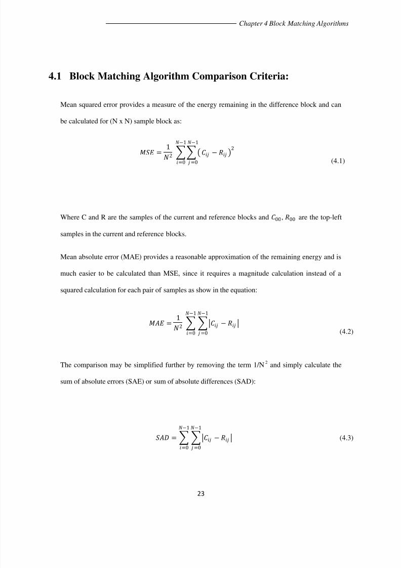
4.1 Block Matching Algorithm Comparison Criteria:
Mean squared error provides a measure of the energy remaining in the difference block and can
be calculated for (N x N) sample block as:
=1
2 − 2
−1
=0
−1
=0
(4.1)
Where C and R are the samples of the current and reference blocks and 00, 00 are the top-left
samples in the current and reference blocks.
Mean absolute error (MAE) provides a reasonable approximation of the remaining energy and is
much easier to be calculated than MSE, since it requires a magnitude calculation instead of a
squared calculation for each pair of samples as show in the equation:
=1
2 −
−1
=0
−1
=0
(4.2)
The comparison may be simplified further by removing the term 1/N2
and simply calculate the
sum of absolute errors (SAE) or sum of absolute differences (SAD):
= − −1
=0
−1
=0
(4.3)

7/30/2019 Motion Compensation based Video Coder
http://slidepdf.com/reader/full/motion-compensation-based-video-coder 37/72
24
Chapter 4 Block Matching Algorithms
Figure 4.2 Full search ‘Raster’ and ‘Spiral’ algorithms
4.2 Search Algorithm for Motion Estimation
In order to find the best matching region in the reference frame, theoretical caring out a
comparison of the current block with every possible candidate in the reference frame, which of
course is impractical because of the large number of comparisons required. In practice a good
match for the current block can usually be found in the immediate neighborhood of the block
position in the reference frame. Hence, in practice the search for a matching region is limited to a
“search widow”, which is centered on the current block position. Search window optimum size
depends on several factors (1) Resolution of each frame (Larger window for higher resolution),
(2) Type of scene (High motion scenes benefit from a larger search window) and finally (3) the
available processing resources as larger window would requires more comparisons and therefore
more processing.
4.2.1 Full Search Block Matching Algorithm
Figure 4.2 Full search ‘Raster’ and ‘Spiral’ algorithms

7/30/2019 Motion Compensation based Video Coder
http://slidepdf.com/reader/full/motion-compensation-based-video-coder 38/72
25
Chapter 4 Block Matching Algorithms
This type of search calculates the comparison criteria at each available position in the search
window, which is computationally intensive especially in large search windows. Raster Full
search motion estimation processes the locations starting from the top-left location as shown in
the figure (4.2) or in a spiral order starting from the position (0, 0) shown in figure (4.2) .The
spiral search order has an advantage over the raster when early termination algorithm are used
because the best match is most likely to be near the center of the search region. Due to the
intensive computations required by the full search, various fast algorithms have been developed ,
which trade off estimation accuracy for reduced computation [6] [12] [13] [14].
4.2.2 Fast Search Block Matching Algorithm
This type of algorithms aims to reduce the number of comparison operations compared to the full
search algorithm, for example; Logarithmic search, Three-step search, Cross search, On-at a time
search, Nearest Neighbors search and the Hierarchical search. Fast search will sample the only
some of the possible locations in the search region. The difference in results is that the difference
block contains more energy than that found by the full search and hence the number of coded bits
generated by the video encoder increase increasing the errors and therefore poorer compression
performance than the full search.
4.2.2.1 Logarithmic Search Strategy
The Logarithmic search is one of the popular techniques used which starts from the position
corresponding to zero displacement and each step tests five points in a diamond arrangement. In
the next step, the diamond search is repeated with its center shifted to the best matching point
resulting from the previous step, while not searching a candidate position if it is outside the search
window. The step size of the search (radius of the diamond) is reduced if the best matching point

7/30/2019 Motion Compensation based Video Coder
http://slidepdf.com/reader/full/motion-compensation-based-video-coder 39/72
26
Chapter 4 Block Matching Algorithms
is the center it‟s self or if it is on the maximum search border range. Otherwise the search step
stays the same. The Logarithmic search is typically accurate for large searching windows and it
returns fast and reasonable quality [6] [12] [13] [14].
Figure 4.3 Fast search ‘Logarithmic’ algorithm

7/30/2019 Motion Compensation based Video Coder
http://slidepdf.com/reader/full/motion-compensation-based-video-coder 40/72
27
Chapter 5 Transform Coding
Chapter Five
5. Transform Coding
Transform Coding is a main point for most of the video coding systems and standards. Spatial image data
(image samples or motion-compensated residual samples) are transformed into a different representation,
the reason is that spatial image data is difficult to compress, neighboring samples are highly correlated
and the energy is distributed across the image, which makes it difficult to discard data or even reduce the
precision of data without disturbing the image quality. This type of coding should compact the image
energy (concentrate the energy into a small number of significant values), decorrelate the data (so that
discarding insignificant data has minimal effect on the image quality) and it should be suitable for
practical implementation in software and hardware.

7/30/2019 Motion Compensation based Video Coder
http://slidepdf.com/reader/full/motion-compensation-based-video-coder 41/72
28
Chapter 5 Transform Coding
5.1 Two Dimensional Discrete Cosine Transform (2-D DCT)
The 2-D DCT version transforms a 2-D block
of samples into a block of coefficients. Figure
(5.1), shows a 720x572 pixel image then taken
an 8x8 block, the next step shows the block
samples values and finally the block is
transformed with 2-D DCT to produce the
coefficients shown in the last part.
The compaction and decorretation performance
of the DCT increases with the increase of block
size, but also computational complexity increases with the block size. A block size of 8x8 is commonly
used in image and video coding applications. This size gives a good compromise between compression
efficiency and computational efficiency. Equation (5.1), is used to calculate the forward DCT for an 8x8
block of image samples [16].
, =()
4 , cos2 + 1
16
7
=0
7
=0
cos2 + 116
(5.1)
The inverse DCT reconstructs a block of image samples from an array of DCT coefficients. The IDCT
takes as its input a block of 8x8 DCT coefficients , and reconstructs a block of 8x8 image samples , Equation (5.2).
, = ()4
, cos2 + 116
7
=0
7
=0
cos2 + 116
(5.2)
Figure 5.1Figure 5.1 2-D DCT performed on an 8x8 block of an image

7/30/2019 Motion Compensation based Video Coder
http://slidepdf.com/reader/full/motion-compensation-based-video-coder 42/72
29
Chapter 5 Transform Coding
Figure (5.2) shows the intensity map for a block
of image samples and next the 2-D DCT
coefficients, which shows that the energy in the
transformed coefficients is concentrated about
the top-left corner of the array of coefficients
“Compaction”. The top-left coefficients
correspond to low frequencies, where there is a
peak in energy in this area and the values
decrease to the bottom right of the array (higher
frequency coefficients)[17] .
5.2 Quantization
The function of the coder is to transmit the DCT block to the decoder, in a bit rate efficient manner, so
that it can perform the inverse transform to reconstruct the image. It has been observed that the numerical
precision of the DCT coefficients may be reduced while still maintaining good image quality at the
decoder. Quantization is used to reduce the number of possible values to be transmitted, reducing the
required number of bits. In practice, this results in the high-frequency coefficients being more quantized
than the low-frequency coefficients. Note that the quantization noise introduced by the coder is not
reversible in the decoder, making the coding and decoding process 'lossy'. At quality 50 (i.e. 84% zeros)
there is almost no visible loss in the image, but there is high compression. At lower quality levels, the
quality goes down by a lot but the compression does not increase that much [16] [17].
Intensity map
DCT coefficients
Figure 5.2 An image with the intensity map along with the compacted vers

7/30/2019 Motion Compensation based Video Coder
http://slidepdf.com/reader/full/motion-compensation-based-video-coder 43/72
30
Chapter 5 Transform Coding
This part shows that the DCT exploits interpixel
redundancies to render excellent decorrelation for most
natural images. Thus, all (uncorrelated) transform
coefficients can be encoded independently without
compromising coding efficiency. In addition, the DCT
packs energy in the low frequency regions. Therefore,
some of the high frequency content can be discarded
without significant quality degradation. Such a
quantization scheme causes further reduction in the
average number of bits per pixel. Lastly, it is concluded
that successive frames in a video transmission exhibit
high temporal correlation. This correlation can be
employed to improve coding efficiency [16] [17].
Figure 5.3 Inverse DCT of Trees; (a) DCT(100%); (b) DCT(75%
DCT(50%); (d) DCT(25%).

7/30/2019 Motion Compensation based Video Coder
http://slidepdf.com/reader/full/motion-compensation-based-video-coder 44/72
31
Chapter 6 Analog Devices Hardware & Software Experience
Chapter six
6. Analog Devices Hardware &
Software Experience
The EZ-KIT Lite includes an ADSP-BF561 Processor desktop
evaluation board along with an evaluation suite of the
VisualDSP++® development and debugging environment with
the C/C++ compiler, assembler, and linker. It also includes
sample processor application programs.
Figure 6.1 Image for BF561 Hardware
7/30/2019 Motion Compensation based Video Coder
http://slidepdf.com/reader/full/motion-compensation-based-video-coder 45/72
32
Chapter 6 Analog Devices Hardware & Software Experience
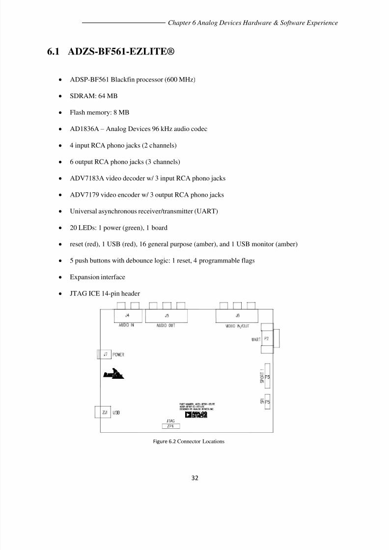
6.1 ADZS-BF561-EZLITE®
ADSP-BF561 Blackfin processor (600 MHz)
SDRAM: 64 MB
Flash memory: 8 MB
AD1836A – Analog Devices 96 kHz audio codec
4 input RCA phono jacks (2 channels)
6 output RCA phono jacks (3 channels)
ADV7183A video decoder w/ 3 input RCA phono jacks
ADV7179 video encoder w/ 3 output RCA phono jacks
Universal asynchronous receiver/transmitter (UART)
20 LEDs: 1 power (green), 1 board
reset (red), 1 USB (red), 16 general purpose (amber), and 1 USB monitor (amber)
5 push buttons with debounce logic: 1 reset, 4 programmable flags
Expansion interface
JTAG ICE 14-pin header
Figure 6.2 Connector Locations

7/30/2019 Motion Compensation based Video Coder
http://slidepdf.com/reader/full/motion-compensation-based-video-coder 46/72
33
Chapter 6 Analog Devices Hardware & Software Experience
6.2 VisualDSP++® Release 5.0
The ADSP-BF561 is supported with a complete set of CROSSCORE®† software and hardware
development tools, including Analog Devices emulators and the VisualDSP++®‡ development
environment. The same emulator hardware that supports other Analog Devices processors also fully
emulates the ADSP-BF561. The VisualDSP++ project management environment lets programmers
develop and debug an application. This environment includes an easy to use assembler that is based on an
algebraic syntax, an archiver (librarian/library builder), a linker, a loader, a cycle-accurate instruction-
level simulator, a C/C++ compiler, and a C/C++ runtime library that includes DSP and mathematical
functions. A key point for these tools is C/C++ code efficiency. The compiler has been developed for
efficient translation of C/C++ code to Blackfin assembly.
VisualDSP++ Features:
The Blackfin processor has architectural features that improve the efficiency of compiled C/C++ code.
The VisualDSP++ debugger has a number of important features. Data visualization is enhanced by a
plotting package that offers a significant level of flexibility. This graphical representation of user data
enables the programmer to quickly determine the performance of an algorithm. As algorithms grow in
complexity, this capability can have increasing significance on the designer‟s development schedule,
increasing productivity. Statistical profiling enables the programmer to nonintrusively poll the processor
as it is running the program. This feature, unique to VisualDSP++, enables the software developer to
passively gather important code execution metrics without interrupting the real-time characteristics of the
program. Essentially, the developer can identify bottlenecks in software quickly and efficiently. By using
the profiler, the programmer can focus on those areas in the program that impact performance and take
corrective action.

7/30/2019 Motion Compensation based Video Coder
http://slidepdf.com/reader/full/motion-compensation-based-video-coder 47/72
34
Chapter 6 Analog Devices Hardware & Software Experience
Debugging both C/C++ and assembly programs with the VisualDSP++ debugger, programmers can:
• View mixed C/C++ and assembly code (interleaved source and object information).
• Insert breakpoints.
• Set conditional breakpoints on registers, memory, and stacks.
• Trace instruction execution.
• Perform linear or statistical profiling of program execution.
• Fill, dump, and graphically plot the contents of memory.
• Perform source level debugging.
• Create custom debugger windows
Figure 6.3 Visual DSP++ Release 5.0

7/30/2019 Motion Compensation based Video Coder
http://slidepdf.com/reader/full/motion-compensation-based-video-coder 48/72
35
Chapter 6 Analog Devices Hardware & Software Experience
6.3 Implementation and Testing
Using the hardware ADSP-BF561 Processor desktop evaluation board along with VisualDSP++ software
to test their performance; Supplying the board with a PAL or NTSC video signal, then buffering the data
in SDRAM. The buffered video frame is then sent out to the video monitor. In this application, no
processing is done on buffered video frames. Connect the board to power supply, Pc with the USB cable
provided then follow these steps to test this application:
1. ADSP-BF561 EZ-KIT LITE SETTINGS
SW2: 1-OFF 2-OFF 3-OFF 4-OFF 5-OFF 6-ON
SW3: 1-OFF 2-ON 3-ON 4-OFF
SW4: 1-ON 2-ON 3-ON 4-ON 5-OFF 6-OFF
SW5: 1-OFF 2-ON 3-ON 4-ON
SW10: 1-OFF 2-OFF 3-OFF 4-OFF 5-OFF 6-OFF
SW11: 1-OFF 2-OFF 3-OFF 4-OFF
SW12: 1-ON 2-ON 3-ON 4-ON
SW13: 1-ON 2-ON

7/30/2019 Motion Compensation based Video Coder
http://slidepdf.com/reader/full/motion-compensation-based-video-coder 49/72
36
Chapter 6 Analog Devices Hardware & Software Experience
2. External connections
Connect a monitor to the EZ-Kit video-out connector and a video source to the EZ-Kit video-in.
The video connectors are the bank of 6 RCA-style jacks nearest the serial cable connector on the
EZ-Kit labeled as J6.
3. Operational Description
Open the "VideoInVideoOut.dpj" project in the VisualDSP++ Integrated Development
Environment.
Under the "Project" tab, select "Build Project" (program is then loaded automatically into
DSP).
Run the executables by pressing "multiprocessor run" (CTRL-F5) on the toolbar.
Halt the processor ("multiprocessor halt" button). If you open a memory window and go to
the addresses of sFrame0, 1, 2, 3, you see the video data of the four frames.
Figure 6.4 Connection to Video In and Video Out devices

7/30/2019 Motion Compensation based Video Coder
http://slidepdf.com/reader/full/motion-compensation-based-video-coder 50/72
37
Chapter 7 Experiment & Analysis
Chapter Seven
7. Experiments &
Analysis
In this part some of the MPEG-2 video compression standard properties and enhancements will be tested,
Using MATLAB® that is a high-level language and interactive environment that enables you to perform
computationally intensive tasks faster than with traditional programming languages. First steps is to load
a video into Matlab and to divide it into number of frames as mentioned before, and then comes the
important part which is to divide each one of these frames into same parts ”macroblocks” which is the
small element that will undergo each operation till the end.
7.1 Exact Procedure
[1] Use command „ fopen’ to load the video file, and then adjust the frame components as the given ratio
4:2:0 for luminance and chrominance ratios. Also calculate the new frame size with the luminance
and chrominance ratios and specify the new number of frames by dividing the file size by the new
frame size.

7/30/2019 Motion Compensation based Video Coder
http://slidepdf.com/reader/full/motion-compensation-based-video-coder 51/72
38
Chapter 7 Experiment & Analysis
[2] The GOP used for this test is [ IBBPBBPBBI ]; therefore the next step is classifying each frame type
so that it‟s easy to call each frame through the process. Using „ fread’ command that reads the video
file data loaded to Matlab as binary format into matrices. Next using „ fseek’ to move between video
frames and classify them.
[3] In this step the P and B-frames should pass through the motion estimation and compensation part.
The main part in this step as mentioned before is to get the motion vectors for each frame along with
the difference frame, introducing the motion estimation function that takes as an input the current
frame that needed to be coded, the reference one, type of search , macroblock size and for sure the
search window size. Dividing the search into three branches; Raster, Spiral and logarithmic search:
Raster search function: This function will calculate first the number of macroblocks
within each frame and then move through these macroblocks within the fixed search
window in a raster way from the beginning of the search window, block by block to the
end to calculate the minimum difference macroblock and to get the motion vectors.
Spiral search function: Operates the same as the raster search function, the only
difference is that this function moves between the macroblocks in a spiral way starting
from the current frame macroblock current location which is the center of the search

7/30/2019 Motion Compensation based Video Coder
http://slidepdf.com/reader/full/motion-compensation-based-video-coder 52/72
39
Chapter 7 Experiment & Analysis
window, that has a computational advantage because the best match is likely to occur
near the center of the search window.
Logarithmic search function: Searches for the best match block in a logarithmic way
that was mentioned in part (4.2.2.1), and also there is another difference as logarithmic
search is a fast search technique not like the raster and spiral full searches. It does take
account for the search window, it searches the whole frame for the best match, but it
takes another parameter as an input rather than the search window, which is the number
of steps in each move “N”.
[4] Second main part for the experiment is the motion compensation; taking as an input the calculated
motion vectors, macroblock size and the reference frame. It creates a new frame with the reference
frame size and first fills it with zeros, then divides the frame into non-overlapping macroblocks and
finally gets the matching macroblock the reference frame.
[5] Introducing the Peak-signal-to-noise-ratio function, which is the main point for all analysis and
measurements, this function takes two frames and calculates the PSNR, actually it takes the current
and the compensated frames to calculate the PSNR for the compensated frame, using Equation (2.1)
and gives the final value in „dB‟.
[6] Discrete cosine transform function is very useful for our analysis, which simply works on an
individual frame to calculate its 2-D DCT coefficients for each block 8x8 pixels and to construct the
DCT image with the preferred quantization weight of compression. First it reads the input image

7/30/2019 Motion Compensation based Video Coder
http://slidepdf.com/reader/full/motion-compensation-based-video-coder 53/72
40
Chapter 7 Experiment & Analysis
using ‘imread’ command, then using ‘Double’ to get better precision for the loaded values of the
image. Next dividing the image into non-overlapping blocks of 8x8 to perform DCT on each block
using ‘dct2’ built-in function on each block. After that multiplying the outcome block by a block of
values which specify the quantization weight (i.e. “1:64”,”10:64”,”32:64”). Inverse DCT is done
easily, again divide the frame into block and perform ‘idct2’ function on each to get the reconstructed
image.
[7] Finally plotting figures and graphs that shows the real and the predicted frames, PSNR for different
frames and different searching types, Complexity for each operation and also DCT and IDCT with
different compression ratios figures.
7.2 Results for Different Schemes
In this part of the thesis, Variation of some parameters will take place and observing there effect on
quality. It is clear and mentioned before that minimizing the macroblock size will give better performance
for this technique of compression that could be easily observed from the outputs quality. Trying to
calculated the PSNR for the first GOP in this video for different macroblock sizes [ 1 , 8 , 16 ] and also
with different search algorithms [Logarithmic, Raster and Spiral search]. Before going through the test
steps, it is important to mention the “uncompressed” video file used and its specifications: The video file
is Foreman.yuv which is very popular in video processing and testing issues. The video was converted
from avi format to yuv format using the Windows Command Processor , this video is a QCIF with 30
frames per second and of resolution 176x144 and of 4:2:0 sub-sampling. Now using different
macroblocks size and keeping the search window constant of 25x25 macroblocks for full search
algorithms and observe the variation of quality for different type of searches.

7/30/2019 Motion Compensation based Video Coder
http://slidepdf.com/reader/full/motion-compensation-based-video-coder 54/72
41
Chapter 7 Experiment & Analysis
Figure 7.1 PSNR for {p} and {B} predicted frames using „Logarithmic search‟
In the above graphs the predicted frames from one to eight between two I-frames are [ B{1} B{2} P{1}
B{3} B{4} P{2} B{5} B{6} ]. Also it is clear that the very small macroblock of 1x1 would result in a
high quality, especially with the full search that tries to find the best match from all the macroblocks. Also
putting into account that the search window is constant of ±7. Moving between the PSNR values, B{1}
and B{2} are of the best PSNR and this was predicted because they use the first “I” frame with first “P”
frame for motion estimation and compensation, Where I-frames are not compressed at all they are sent
with full details and the first P-frame is always not that bad because it is predicted from an I-frame,
therefore the first two Bs are of the highest PSNR values. Next mentioning the second P frame that has
the worst PSNR value because it was predicted from a predicted frame P{1}. After that the last two Bs
again rise to high quality as they got near to an I-frame.

7/30/2019 Motion Compensation based Video Coder
http://slidepdf.com/reader/full/motion-compensation-based-video-coder 55/72
42
Chapter 7 Experiment & Analysis
Figure 7.2 PSNR for {p} and {B} predicted frames using „Raster full search‟
Figure 7.3 PSNR for {p} and {B} predicted frames using „Spiral full search‟

7/30/2019 Motion Compensation based Video Coder
http://slidepdf.com/reader/full/motion-compensation-based-video-coder 56/72
43
Chapter 7 Experiment & Analysis
Now it is very clear and obvious that the performance of the two full search algorithms is higher than the
fast search algorithm “Logarithmic search”. Also it is important to mention that both “Raster and Spiral
full search algorithms” resulted in the same PSNR values as they work the same way by searching the
whole search window, but only differs in technique.
Figure 7.4 PSNR for predicted frames “Foreman video” using „Raster full search‟ different search window size
In Figure( 7.4), the PSNR values for the predicted frames with the change in the search window keeping a
constant macroblock size of 8x8 pixels, Using the “raster full search” it is obvious that increasing the
region of search will result in more precision and accuracy in finding the best match. Also Figure (7.4)
shows that all the predicted frame PSNR will change together as the macroblock size is constant, taking a
wise look at the figure, it can be concluded that the differ ence between search window “±7” and “±15”
is larger than the difference between “±15” and “±25”, as increasing the search window so much will
not give much better quality as the macoblock being searched for, will likely be near its original position
for most of the video scenes.

7/30/2019 Motion Compensation based Video Coder
http://slidepdf.com/reader/full/motion-compensation-based-video-coder 57/72
44
Chapter 7 Experiment & Analysis
Testing another video file “Stephan”, which is important for our test as this video scenes contain a lot of
motion and variation between its frames in a tennis match, this video is a CIF with 30 frames per second
and of resolution 352x288 and of 4:2:0 sub-sampling. Testing for different macroblock size keeping a
constant search window of ±25 for full search algorithms and observe the variation of quality for
different type of searches. Also testing different search window size and keeping the macrobloack size
constant of 8x8.
Figure 7.5 PSNR for {p} and {B} predicted "Stephan video" frames using 'Logarithmic search‟
Figure 7.6 PSNR for {p} and {B} predicted "Stephan video" frames 'Full search algorithms‟

7/30/2019 Motion Compensation based Video Coder
http://slidepdf.com/reader/full/motion-compensation-based-video-coder 58/72
45
Chapter 7 Experiment & Analysis
A noteworthy point out of the previous two graphs is that, for a macroblock size of 1x1 there is a huge
difference in the resulting PSNR between fast and full search algorithms, but the both macroblock sizes
8x8 and 16x16 the PSNR values are almost the same, which means that in a rapid motion scene “Tennis
match” using different search techniques with a large block size will not improve the quality and the only
way to increase the PSNR values is to minimize the macroblock size.
As more support for our compression technique, testing another video file “Fish”, which is also well
known for video processing and testing issues, this video is a CIF with 30 frames per second and of
resolution 352x288 and of 4:2:0 sub-sampling. Testing with different macroblock size and different
search algorithms, keeping a constant search window of ±25 for full search algorithms. Also testing
different search window size and keeping the macroblock size constant of 8x8.
Figure 7.7 PSNR for {p} and {B} predicted "Stephan video" frames for different search windows 'Raster full search algorithm‟

7/30/2019 Motion Compensation based Video Coder
http://slidepdf.com/reader/full/motion-compensation-based-video-coder 59/72
46
Chapter 7 Experiment & Analysis
Figure 7.8 PSNR for {p} and {B} predicted "Fish video" frames using 'Logarithmic fast search algorithm‟
Figure 7.10Figure 7.9 PSNR for {P} and {B} predicted “Fish video” frames using „Raster full search algorithm‟

7/30/2019 Motion Compensation based Video Coder
http://slidepdf.com/reader/full/motion-compensation-based-video-coder 60/72
47
Chapter 7 Experiment & Analysis
Figure 7.10 PSNR for {p} and {B} predicted "Fish video" frames different search windows using 'Raster full search algorithm‟
Fine looking to the above figure, it can be observed that the PSNR values for both search windows
[±15 ± 25] are the same, Since “Fish” video is a yellow fish moving along with the capturing
device, there is no need for a large window size and exhaustive searching between the block, as it is likely
to find the matching region very near to the current frame original position. Therefore increasing the
search window than ±15 will increase nothing to quality.

7/30/2019 Motion Compensation based Video Coder
http://slidepdf.com/reader/full/motion-compensation-based-video-coder 61/72
48
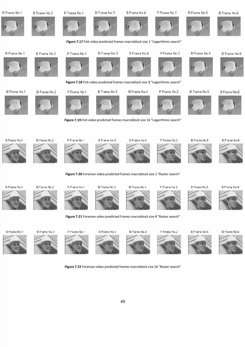
Chapter 7 Experiment & Analysis
Figure 7.11 Foreman video predicted frames macroblock size 1 "Logarithmic search"
Figure 7.12 Foreman video predicted frames macroblock size 8 "Logarithmic search"
Figure 7.13 Foreman video predicted frames macroblock size 16 "Logarithmic search"
Figure 7.14 Stephan video predicted frames macroblock size 1 "Logarithmic search"
Figure 7.15 Stephan video predicted frames macroblock size 8 "Logarithmic search"
Figure 7.16 Stephan video predicted frames macroblock size 16 "Logarithmic search"
7/30/2019 Motion Compensation based Video Coder
http://slidepdf.com/reader/full/motion-compensation-based-video-coder 62/72
49
Chapter 7 Experiment & Analysis
Figure 7.17 Fish video predicted frames macroblock size 1 "Logarithmic search"
Figure 7.18 Fish video predicted frames macroblock size 8 "Logarithmic search"
Figure 7.19 Fish video predicted frames macroblock size 16 "Logarithmic search"
Figure 7.20 Foreman video predicted frames macroblock size 1 "Raster search"
Figure 7.21 Foreman video predicted frames macroblock size 8 "Raster search"
Figure 7.22 Foreman video predicted frames macroblock size 16 "Raster search"

7/30/2019 Motion Compensation based Video Coder
http://slidepdf.com/reader/full/motion-compensation-based-video-coder 63/72
50
Chapter 7 Experiment & Analysis
Figure 7.24 Stephan video predicted frames macroblock size 8 "Raster search"
Figure 7.23 Stephan video predicted frames macroblock size 1 "Raster search"
Fi ure 7.26 Fish video redicted frames macroblock size 1 "Raster search"
Figure 7.25 Stephan video predicted frames macroblock size 16 "Raster search"
Figure 7.28 Fish video predicted frames macroblock size 16 "Raster search"
Figure 7.27 Fish video predicted frames macroblock size 8 "Raster search"

7/30/2019 Motion Compensation based Video Coder
http://slidepdf.com/reader/full/motion-compensation-based-video-coder 64/72
51
Chapter 7 Experiment & Analysis
Figure 7.29 PSNR values for "Foreman video" with search window 7 using 'Raster full search'
Figure 7.30 PSNR values for "Foreman video" with search window 15 using 'Raster full search'
Figure 7.31 PSNR values for "Foreman video" with search window 25 using 'Raster full search'
Figure 7.32 PSNR values for "Stephan video" with search window 7 using 'Raster full search'
Figure 7.33 PSNR values for "Stephan video" with search window 15 using 'Raster full search'
Figure 7.34 PSNR values for "Stephan video" with search window 25 using 'Raster full search'

7/30/2019 Motion Compensation based Video Coder
http://slidepdf.com/reader/full/motion-compensation-based-video-coder 65/72

7/30/2019 Motion Compensation based Video Coder
http://slidepdf.com/reader/full/motion-compensation-based-video-coder 66/72
53
Chapter 7 Experiment & Analysis
Introducing “Transform coding” as two-dimensional discrete cosine transform to the compression coder,
passing the I-frames over the 2-D DCT for more compression as the I-frames or only coded without any
prediction, where there isn‟t any compression. Hence, 2-D DCT will effectively improve the compression
technique, testing the performance and the quality of the predicted frames using several DCT
compression qualities (i.e. Different Quantization compression ratios 1:64, 10:64, 21:64 and 36:64) on
video sequence “foreman” for a macroblock size of 8x8 and a search window ±7 for simplicity and
noticing the variation of the predicted frames.
Figure 7.38 PSNR for predicted frames using different 2D-DCT Compression Qualities

7/30/2019 Motion Compensation based Video Coder
http://slidepdf.com/reader/full/motion-compensation-based-video-coder 67/72
54
Chapter 7 Experiment & Analysis
Figure 7.39 foreman video predicted frames "NO DCT"
Figure 7.40 foreman video predicted frames "DCT 36:64"
Figure 7.41 foreman video predicted frames "DCT 21:64"
Figure 7.42 foreman video predicted frames "DCT 10:64"
Figure 7.43 foreman video predicted frames "DCT 1:64"

7/30/2019 Motion Compensation based Video Coder
http://slidepdf.com/reader/full/motion-compensation-based-video-coder 68/72
55
Chapter 8 Conclusion & Future Work
Chapter Eight
8. Conclusion &
Future Work
8.1 Conclusion
In this thesis, various techniques for motion estimation block matching algorithm were implemented and
tested, then the complete hybrid motion estimator and compensator with discrete cosine transform was
also tested. Results from the previous chapter conducted that; (1) Full search algorithms will always lead
to a better visual quality than fast search algorithms, but unfortunately with a significant increase in
execution time due to the search strategy complexity. (2) Smaller macroblock size will enhance the block
matching algorithm therefore will increase the probability of finding the best match block in the reference
frame which will result in better quality for all video sequences tested. (3) Increasing the Search window
will also give more flexibility for the algorithm to find the best matching block, trying different search
window sizes for various videos, it was obvious that in terms of PSNR the result was significantly
improved. As an important point to mention, Fish video gave the same results for both search windows
(15, 25) which means that increasing the search window more than a certain threshold for video with low

7/30/2019 Motion Compensation based Video Coder
http://slidepdf.com/reader/full/motion-compensation-based-video-coder 69/72
56
Chapter 8 Conclusion & Future Work
motion characteristics will increase nothing to quality and will increase execution time. On the other hand
for Stephan video the frames difference is high recognized which means that block (if they are the same
ones) will change their locations rapidly and therefore increasing the search window and searching in a
larger region will obviously give better quality. Next the part containing the DCT for the I-frames, we can
conclude that, DCT will increase the compression as I-frames are coded without any prediction, therefore
transform coding these frames will be an effective step for minimization of data. As the DCT is one of the
lossy types of compression, therefore it will show degradation in visual quality. Testing different
quantizer compression matrices will lead to different visual qualities as shown in part (7.2) as the
compression increases from 64:64 (i.e. no compression) till 1:64 (i.e. Highest compression) the quality
also inversely changes with the compression ratio.
8.2 Future work:
Techniques enhancing the Motion estimation block matching coder performance
Many empirical researches are being tested nowadays to:
1. Improve the predicted frames (decoded frames) quality.
2. Decrease the algorithm computational complexity.
3. Modify the coder to achieve efficient execution time.
4. Increase coding efficiency.
Describing some of the most obvious and novel improvements to our thesis, we concluded that changing
the search window for example for different videos yield different results and hence quality differs, there
are many experiments done to try to take
advantage of changing the search window with
the type of video, “Search Window Size
Decision‟, is an innovative topic enhancing this
Figure 8.1 Block diagram for Search window size decision after motion is detect

7/30/2019 Motion Compensation based Video Coder
http://slidepdf.com/reader/full/motion-compensation-based-video-coder 70/72
57
Chapter 8 Conclusion & Future Work
hybrid coder efficiency, where its main idea is applying a Motion Detection Algorithm for the decision of
the search window in the motion estimation, which will reduce the coder‟s complexity[20]. Another
innovative feature used in H.264/MPEG-4 AVC is the Block Size Selection Algorithm for inter-frame
coding, which will increase the encoder efficiency, but with insignificant degradation in the picture
quality. Results of the algorithm demonstrate a speed up in encoding time of up to 73% compared with
the H.264 benchmark. Block size is no longer fixed, but ranges from 4x4 to 16x16 for inter-frame coding
[21].
Since the performances of any of the mentioned algorithms highly depend on the characteristics of the
video contents, there is no single algorithm that can adapt to all kinds of video contents. A multiple stage
motion estimation scheme for video compression was proposed that tackles this issue, which is called
Content Adaptive Search Technique (CAST) and can provide adaptability to the video contents to
maximize the overall performance. CAST scheme consists of four stages; motion vector field prediction,
block-based segmentation, motion parameter extraction, and adaptive search strategy. Through pre-
processing the motion vector field of the previous reference frame in the first three stages, CAST extracts
the motion parameters for each region. The 4th
stage is a combination of various techniques including
motion vector prediction, search area decision and an adaptive fast search algorithm that is adjusted by a
mathematical model for the block distortion surface (BDS). CAST scheme improves the visual quality,
while yielding a faster speed, comparing with the other predictive ME algorithms [22].

7/30/2019 Motion Compensation based Video Coder
http://slidepdf.com/reader/full/motion-compensation-based-video-coder 71/72
58
References
[1] S.Dhahri, A.Zitouni, H. Chaouch, and R. Tourki, “ Adaptive Motion Estimator Based on Variable Block Size Scheme”, Proceedings of World Academy of Science, Engineering and Technology,
Volume: 38, February 2009.
[2] U-V.Koc, “Low Complexity and High Throughput Fully DCT-Based Motion Compensated Video
Coders”, National Science Foundation Engineering Research Center Program, University of Maryland, Harvard University, 1996
[3] Fayez M.Idris, “ An Algorithm and Architecture for Video Compression”, School of GraduatesStudies and Research, University of Ottawa, 1993.
[4] Lai Kam Cheong, “ Enhancing Techniques for a Standard Conforming Real-Time Video Codec”,
Department of Electronic and Information Engineering The Hang Kong Polytechnic University,September 2002
[5] Colin E.manning, “Motion Compensated Video Compression Overview”,http://www.newmediarepublic.com/dvideo/compression/adv08.html#blockmatching
[6] Iain E. G. Richardson, “VIDEO CODEC DESIGN: Developing Image and Video Compression
Systems”, Chichester : Wiley, 2002.
[7] John G. Proakis, Dimitris G. Manolakis, “ DIGITAL SIGNAL PROCESSING”, 4th edition,
Prentice Hall, 2007.
[8] Yao Wang, Jorn Ostermann, Ya-Qin Zhang, “VIDEO PROCESSING AND
COMMUNICATIONS ”, Prentice Hall, Upper Saddle River, NJ 07458, 2002.
[9] Dave Marshall, http://www.cs.cf.ac.uk/Dave/Multimedia/node256.html, April 2001.
[10] Dr. Leonardo Chiariglione, http://www.chiariglione.org/mpeg/index.asp, I-10040 Villar Dora,
ITALY.
[11] A. Zakhor, “ EECS 290T: Multimedia Signal Processing, Communications and Networking”,University of California at Berkeley department of Electrical Engineering & Computer Sciences,
Spring 2004, http://inst.eecs.berkeley.edu/~ee290t/sp04/
[12] K. R. Rao, Z. S. Bojkovic, D. A. Milovanovic, “ Multimedia Communication Systems:
Techniques, Standard and Networks”, Prentice Hall PTR, 2002.

7/30/2019 Motion Compensation based Video Coder
http://slidepdf.com/reader/full/motion-compensation-based-video-coder 72/72
[13] J.G. Apostolopoulos and S.J. Wee, ``Video Compression Standards'', Wiley Encyclopedia of
Electrical and Electronics Engineering, John Wiley & Sons, Inc., New York, 1999.
[14] V. Bhaskaranand K. Konstantinides, Image and Video Compression Standards: Algorithms and
Architectures, Boston, Massachusetts: KluwerAcademic Publishers, 1997.
[15] Yu- Nan Pan, “ A Fast Search Algorithm for Motion Estimation on H.264/AVC ”, Department of
Electrical Engineering National Central University, Jhongli 320, Taiwan, July 2004.
[16] Syed Ali Khayam,” The Discrete Cosine Transform (DCT): Theory and Application”, Department of Electrical & Computer Engineering, Michigan State University, March 2003.
[17] Ken Kabeen, Peter Gent, “ Image Compression and the Discrete Cosine Transform”, College of the Redwoods.
[18] Processor Development Tools http://www.autex.ru/dspa/dspa2008/04.pdf
[19] ADSP-BF561 EZ-KIT Lite® Evaluation System Manual, 2008 Analog Devices, Inc.,
http://www.analog.com/static/imported-files/eval_kit_manuals/ADSP-BF561%20EZ-
KIT%20LIte%20Manual%20Rev%203-2%20March%202008.pdf
[20] Gianluca Bailo, Massimo Bariani, Ivano Barbieri, Marco Raggio,” Search Window Size Decision
for Motion Estimation Algorithm in H.264 Video Coder ”, Department of Biophysical andElectronic Engineering, University of Geova, ITALY, 2004
[21] Hyungjoon Kim and Yucel Altunbasak,” Low-Complexity Macroblock Mode Selection for
H.264/AVC Encoders”, Center of Signal and Image processing, Georgia Institute of Technology,
Atlanta, 2004.
[22] Jiancong Luo, Ishfaq Ahmed, Yu Sun and Yongfang Liang,” A Multistage Fast Motion
Estimation Scheme for Video Compression”, Department of computer Science and Engineering,
University of Texas, Arlington, 2004.