motherboaga-7vkmp series amd athlon™/athlon™ xp/duron™ socket a processor motherboard
DESCRIPTION
GA-7VKMP SeriesAMD Athlon™/Athlon™ XP/Duron™ Socket AProcessor MotherboardUSER'S MANUALTRANSCRIPT

M The author assumes no responsibility forany errors or omissions that may appearin this document nor does the author makea commit ment to up date the informationcontained herein.
M Third-party brands and names are theproperty of their respective owners.
M Please do not remove any labels onmotherboard, this may void the warranty ofthis motherboard.
M Due to rapid change in technology, someof the specifications might be out of datebefore publication of this booklet.


Declaration of ConformityWe, Manufacturer/Importer
(full address)G.B.T. Technology Träding GMbH
Ausschlager Weg 41, 1F, 20537 Hamburg, Germany
declare that the product( description of the apparatus, system, installation to which it refers)
Mother BoardGA-7VKMP
is in conformity with(reference to the specification under which conformity is declared)
in accordance with 89/336 EEC-EMC Directive
EN 55011 Limits and methods of measurementof radio disturbance characteristics ofindustrial,scientific and medical (ISMhigh frequency equipment
EN 61000-3-2* EN 60555-2
Disturbances in supply systems causeby household appliances and similarelectrical equipment “Harmonics”
EN 55013 Limits and methods of measurementof radio disturbance characteristics ofbroadcast receivers and associatedequipment
EN 61000-3-3* Disturbances in supply systems causeby household appliances and similarelectrical equipment “Voltage fluctuations”
EN 55014 Limits and methods of measurementof radio disturbance characteristics ofhousehold electrical appliances,portable tools and similar electricalapparatus
EN 50081-1 Generic emission standard Part 1:
Residual commercial and light industry
EN 50082-1 Generic immunity standard Part 1:Residual commercial and light industry
EN 55015 Limits and methods of measurementof radio disturbance characteristics offluorescent lamps and luminaries
Generic emission standard Part 2:Industrial environment
EN 55081-2
Immunity from radio interference ofbroadcast receivers and associatedequipment
Generic emission standard Part 2:
Industrial environment
EN 55082-2
EN 55022 Limits and methods of measurementof radio disturbance characteristics ofinformation technology equipment
lmmunity requirements for householdappliances tools and similar apparatus
ENV 55104
Cabled distribution systems; Equipmentfor receiving and/or distribution fromsound and television signals
EMC requirements for uninterruptiblepower systems (UPS)
EN50091-2
EN 55020
DIN VDE 0855 part 10 part 12
(EC conformity marking) CE marking
The manufacturer also declares the conformity of above mentioned productwith the actual required safety standards in accordance with LVD 73/23 EEC
Safety requirements for mains operatedelectronic and related apparatus forhousehold and similar general use
EN 60950 EN 60065
Safety of household and similarelectrical appliances
EN 60335
Manufacturer/Importer
Signature:Name:(Stamp)
Date : July 23, 2002
EN 60555-3
Timmy HuangTimmy Huang
EN 50091-1
Safety for information technology equipmentincluding electrical bussiness equipment
General and Safety requirements foruninterruptible power systems (UPS)

FCC Part 15, Subpart B, Section 15.107(a) and Section 15.109(a),Class B Digital Device
DECLARATION OF CONFORMITYPer FCC Part 2 Section 2.1077(a)
Responsible Party Name:
Address:
Phone/Fax No:hereby declares that the product
Product Name:
Conforms to the following specifications:
This device complies with part 15 of the FCC Rules. Operation issubject to the following two conditions: (1) This device may notcause harmful and (2) this device must accept any inference received,including that may cause undesired operation.
Representative Person’s Name:
Signature: Eric Lu
Supplementary Information:
Model Number:
17358 Railroad StreetCity of Industry, CA 91748
G.B.T. INC. (U.S.A.)
(818) 854-9338/ (818) 854-9339
MotherboardGA-7VKMP
Date:
ERIC LU
July 23, 2002

USER'S MANUAL
GA-7VKMP SeriesAMD Athlon™/Athlon™ XP/Duron™ Socket A
Processor Motherboard
AMD Athlon™/Athlon™ XP/Duron™ Socket A Processor MotherboardRev. 3401
12ME-7VKMP-3401

- 2 -GA-7VKMP Series Motherboard
Engl
ish
Table of Content
Item Checklist ......................................................................................... 4WARNING ! .............................................................................................. 4
Chapter 1 Introduction ............................................................................ 5Features Summary ...................................................................................... 5GA-7VKMP / GA-7VKMP-P Motherboard Layout ........................................ 7GA-7VKMP-SI Motherboard Layout ............................................................ 8
Chapter 2 Hardware Installation Process ............................................... 9Step 1: Install the Central Processing Unit (CPU) .....................................10
Step 1-1: CPU Speed Setup .......................................................................................... 10Step 1-2: CPU Installation .............................................................................................. 11Step 1-3: CPU Heat Sink Installation ............................................................................12
Step 2: Install memory modules ................................................................ 13Step 3: Install expansion cards .................................................................14Step 4: Connect ribbon cables, cabinet wires and power supply ............ 15
Step 4-1 : I/O Back Panel Introduction ......................................................................... 15Step 4-2 : Connectors Introduction ................................................................................ 17
Chapter 3 BIOS Setup .........................................................................25The Main Menu (For example: BIOS Ver. : F1h) ...................................... 26Standard CMOS Features .........................................................................28BIOS Features Setup .................................................................................31Chipset Features Setup .............................................................................33Power Management Setup .......................................................................36

Table of Content
English
- 3 -
PNP/PCI Configuration .............................................................................. 39Load Fail-Safe Defaults .............................................................................41Load Optimized Defaults ...........................................................................42Integrated Peripherals ...............................................................................43Hardware Monitor & MISC Setup .............................................................. 47Set Supervisor / User Password ................................................................ 49IDE HDD Auto Detection............................................................................ 50Save & Exit Setup .......................................................................................51Exit Without Saving .................................................................................... 52
Chapter 4 Technical Reference ........................................................... 55Block Diagram ...........................................................................................55Q-Flash Utility Introduction ........................................................................ 56@BIOS™ Introduction.................................................................................58EasyTune ™ 4 Introduction .........................................................................592- / 4- / 6-Channel Audio Function Introuction( ) ............................................................... 60
Chapter 5 Appendix .............................................................................67
For GA-7VKMP only. For GA-7VKMP-P only. For GA-7VKMP-SI only.
- 4 -GA-7VKMP Series Motherboard
Engl
ish Item Checklist
The GA-7VKMP Series motherboardIDE cable x 1 / Floppy cable x 1CD for motherboard driver & utilityGA-7VKMP Series user's manualI/O ShieldQuick PC Installation GuideRAID Manual
2 Port USB Cable x 14 Port USB Cable x 1SPDIF KIT x 1 (SPD-KIT)IEEE 1394 Cable x1Center/Subwoofer Cable x 1 (SURROUND-KIT)
Motherboard Settings Label
Computer motherboards and expansion cards contain very delicate Integrated Circuit (IC) chips. Toprotect them against damage from static electricity, you should follow some precautions whenever youwork on your computer.
1. Unplug your computer when working on the inside.2. Use a grounded wrist strap before handling computer components. If you do not have one, touch
both of your hands to a safely grounded object or to a metal object, such as the power supplycase.
3. Hold components by the edges and try not touch the IC chips, leads or connectors, or othercomponents.
4. Place components on a grounded antistatic pad or on the bag that came with the componentswhenever the components are separated from the system.
5. Ensure that the ATX power supply is switched off before you plug in or remove the ATX powerconnector on the motherboard.
If the motherboard has mounting holes, but they don't line up with the holes on the base and thereare no slots to attach the spacers, do not become alarmed you can still attach the spacers to themounting holes. Just cut the bottom portion of the spacers (the spacer may be a little hard to cut off, sobe careful of your hands). In this way you can still attach the motherboard to the base without worryingabout short circuits. Sometimes you may need to use the plastic springs to isolate the screw from themotherboard PCB surface, because the circuit wire may be near by the hole. Be careful, don't let thescrew contact any printed circuit write or parts on the PCB that are near the fixing hole, otherwise itmay damage the board or cause board malfunctioning.
Installing the motherboard to the chassis…
WARNING!

Introduction
English
- 5 -
Form Factor 24.3cm x 21.0cm Micro ATX size form factor, 4 layers PCBMotherboard GA-7VKMP Series Motherboard:
GA-7VKMP, GA-7VKMP-P or GA-7VKMP-SICPU Socket A processor
AMD Athlon™/Athlon™ XP/Duron™ (K7) Socket A processor128K L1 & 256K/64K L2 cache on die200/266MHz FSB and DDR bus speedsSupports 1.4GHz and faster
Chipset VIA KM266 Memory/AGP/PCI Controller(PAC)VT8235V-LINK Client Highly Integrated
Memory 2 184-pin DDR DIMM socketsSupports DDR DRAM PC1600/PC2100Supports up to 1GB DDR (Max)Supports only 2.5V DDR DIMM
I/O Control ITE8705FSlots 1 Universal AGP slot (1X/2X/4X) device support
3 PCI slot supports 33MHz & PCI 2.2 compliantOn-Board IDE 2 IDE bus master (DMA33/ATA66/ATA100/ATA133) IDE ports
for up to 4 ATAPI devicesSupports PIO mode3,4 (UDMA 33/ATA66/ATA100/ATA133) IDE& ATAPI CD-ROM
On-Board Peripherals 1 Floppy port supports 2 FDD with 360K, 720K, 1.2M, 1.44M and 2.88M bytes1 Parallel port supports Normal/EPP/ECP mode2 Serial ports (COM A, Internal COM B), 1 VGA port6 USB ports (2 x Rear, 4 x Front by cable)1 Front Audio connector1 IrDA connector for IR
Chapter 1 Introduction
to be continued......
Features Summary

- 6 -GA-7VKMP Series Motherboard
Engl
ish
Please set the CPU host frequency in accordance with your processor's specifications.We don't recommend you to set the system bus frequency over the CPU's specificationbecause these specific bus frequencies are not the standard specifications for CPU, chipsetand most of the peripherals. Whether your system can run under these specific busfrequencies properly will depend on your hardware configurations, including CPU, Chipsets,SDRAM, Cards…etc.
On-Board Sound Realtek ALC101 CODEC( ) or Realtek ALC650 CODEC( )
Line Out / 2 front speaker ( )
Line In / 2 rear speaker (by s/w switch)( )
Mic In / center & subwoofer (by s/w switch)( )
SPDIF In ( ) / out ( )
1 BuzzerLine Out / Line In / Mic In / CD In / AUX In / Game port
On-Board LAN Build in RTL8100BL ChipsetHardware Monitor CPU/System Fan Revolution detect
CPU/System Fan ControlCPU Overheat WarningSystem Voltage Detect
PS/2 Connector PS/2 Keyboard interface and PS/2 Mouse interaceBIOS Licensed AMI BIOS, 2M bit FWH
Supports Q-FlashAdditional Features PS/2 KB/Mouse wake up from S1
USB KB/Mouse wake up from S3AC RecoverySupports STR (Suspend-To-RAM)Supports @BIOS™
Supports EasyTune™ 4
For GA-7VKMP only. For GA-7VKMP-P only. For GA-7VKMP-SI only.

Introduction
English
- 7 -
For GA-7VKMP only. For GA-7VKMP-P only. For GA-7VKMP-SI only.
GA-7VKMP / GA-7VKMP-P Motherboard Layout
GA-7V
KMP
KB_MS
COMA
LPT
GAME
LINE_
INLINE_
OUT
MIC_
INUS
B
LAN
COMB
CD_IN
F_AUDIO
F_PANEL
BATTERY
PWR_LED
VIA KM266
SOCKET A
CPUFAN
ATX
FDD ID
E1
IDE2
PCI1
PCI2
PCI3
DDR2
DDR1
CODEC
ITE8
705F
BIOS
F_USB1
VGA
SYSFAN
AGP
VIA VT8235
CLK_JP
RAM_LED
RTL8100BL
AUX_IN
CI
IR
F_USB2
BUZZER
SUR_CEN( )
SPDIF( ) SPDIF_IN( )
-P
- 8 -GA-7VKMP Series Motherboard
Engl
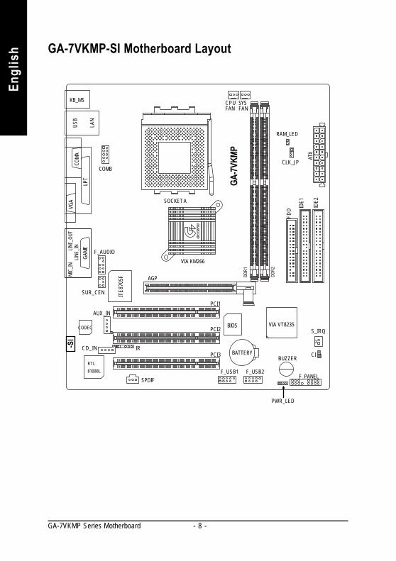
ish GA-7VKMP-SI Motherboard Layout
GA-7V
KMP
KB_MS
COMA
LPT
GAME
LINE_
INLINE_
OUT
MIC_
INUS
B
LAN
COMB
CD_IN
F_AUDIO
F_PANEL
BATTERY
PWR_LED
VIA KM266
SOCKET A
CPUFAN
ATX
FDD ID
E1
IDE2
PCI1
PCI2
PCI3
DDR2
DDR1
CODEC
ITE8
705F
BIOS
F_USB1
VGA
SYSFAN
AGP
VIA VT8235
CLK_JP
RAM_LED
RTL8100BL
AUX_IN
CIIR
F_USB2
BUZZER
SUR_CEN
SPDIF
S_IRQ
-SI

- 9 - Hardware Installation Process
EnglishTo set up your computer, you must complete the following steps:Step 1 -Set system Jumper (CLK_JP)Step 2 - Install the Central Processing Unit (CPU)Step 3 - Install memory modulesStep 4 - Install expansion cardsStep 5 -Connect ribbon cables, cabinet wires and power supplyStep 6 -Setup BIOS softwareStep 7 - Install supporting software tools
Chapter 2 Hardware Installation Process
Step 3
Step 4
Step 5
Step 5
Step2Step 1

- 10 -GA-7VKMP Series Motherboard
Engl
ish Step 1: Install the Central Processing Unit (CPU)
Step 1-1: CPU Speed SetupThe system bus frequency can be switched at 100/133MHz and auto by adjusting CLK_JP.(The frequency ratio depend on CPU.)
1-2 close: 100MHz
1
1
2-3 close: 133MHz
CLK_JP
- 11 - Hardware Installation Process
English
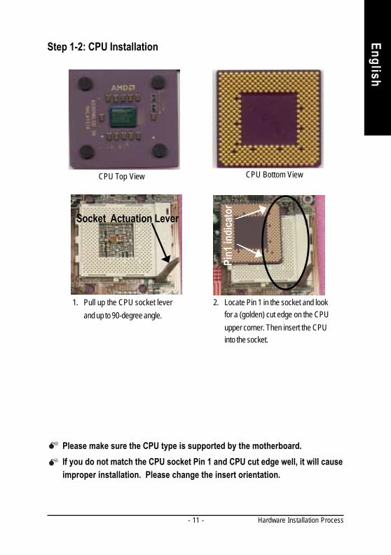
Step 1-2: CPU Installation
If you do not match the CPU socket Pin 1 and CPU cut edge well, it will cause improper installation. Please change the insert orientation.
CPU Top View CPU Bottom View
1. Pull up the CPU socket leverand up to 90-degree angle.
2. Locate Pin 1 in the socket and lookfor a (golden) cut edge on the CPUupper corner. Then insert the CPUinto the socket.
Please make sure the CPU type is supported by the motherboard.
Socket Actuation LeverPi
n1 in
dica
tor

- 12 -GA-7VKMP Series Motherboard
Engl
ish Step 1-3: CPU Heat Sink Installation
1. Press down the CPU socket lever and finish CPU installation.
Please use AMD approved cooling fan.We recommend you to apply the thermal paste to provide better heatconduction between your CPU and heatsink.Make sure the CPU fan power cable is plugged in to the CPU fan connector,this completes the installation.Please refer to CPU heat sink user's manual for more detail installationprocedure.
3. Fasten the heatsink supporting-base onto the CPU socket on themotherboard.
2. Use qualified fan approved by AMD.
4. Make sure the CPU fan is pluggedto the CPU fan connector, than in-stall complete.

- 13 - Hardware Installation Process
English
When RAM_LED is ON, you do not install / remove DDR from socket.Please note that the DIMM module can only fit in one direction due to the twonotches. Wrong orientation will cause improper installation. Please changethe insert orientation.
DDR
1. The DIMM socket has a notch, so the DIMMmemory module can only fit in one direction.
2. Insert the DIMM memory module vertically into theDIMM socket. Then push it down.
3. Close the plastic clip at both edges of the DIMMsockets to lock the DIMM module.
Reverse the installation steps when you wish toremove the DIMM module.
Step 2: Install memory modulesThe motherboard has 2 dual inline memory module (DIMM) sockets. The BIOS will automatically
detects memory type and size. To install the memory module, just push it vertically into the DIMMsocket. The DIMM module can only fit in one direction due to the notch. Memory size can varybetween sockets.
Total Memory Sizes With Unbuffered DDR DIMM Devices used on DIMM 1 DIMM x 64 / x 72 2 DIMMs x 64 / x 72 64 Mbit (2Mx8x4 banks) 128 MBytes 256 MBytes 64 Mbit (1Mx16x4 banks) 32 MBytes 64 MBytes 128 Mbit(4Mx8x4 banks) 256 MBytes 512 MBytes 128 Mbit(2Mx16x4 banks) 64 MBytes 128 MBytes 256 Mbit(8Mx8x4 banks) 512 MBytes 1 GBytes 256 Mbit(4Mx16x4 banks) 128 MBytes 256 MBytes 512 Mbit(8Mx16x4 banks) 256 MBytes 512 MBytes

- 14 -GA-7VKMP Series Motherboard
Engl
ish
Step 3: Install expansion cards1. Read the related expansion card’s instruction document before install the expansion card into the
computer.2. Remove your computer’s chassis cover, necessary screws and slot bracket from the computer.3. Press the expansion card firmly into expansion slot in motherboard.4. Be sure the metal contacts on the card are indeed seated in the slot.5. Replace the screw to secure the slot bracket of the expansion card.6. Replace your computer’s chassis cover.7. Power on the computer, if necessary, setup BIOS utility of expansion card from BIOS.8. Install related driver from the operating system.
AGP Card
Please carefully pull out the small white-drawable bar at the end of the AGP slot whenyou try to install/ uninstall the AGP card. Pleasealign the AGP card to the onboard AGP slotand press firmly down on the slot. Make sureyour AGP card is locked by the small white-drawable bar.
Established on the existing SDRAM industry infrastructure, DDR (Double Data Rate) memory isa high performance and cost-effective solution that allows easy adoption for memory vendors, OEMsand system integrators.
DDR memory is a sensible evolutionary solution for the PC industry that builds on the existingSDRAM infrastructure, yet makes awesome advances in solving the system performance bottleneckby doubling the memory bandwidth. DDR SDRAM will offer a superior solution and migration path fromexisting SDRAM designs due to its availability, pricing and overall market support. PC2100 DDRmemory (DDR266) doubles the data rate through reading and writing at both the rising and falling edgeof the clock, achieving data bandwidth 2X greater than PC133 when running with the same DRAMclock frequency. With peak bandwidth of 2.1GB per second, DDR memory enables system OEMs tobuild high performance and low latency DRAM subsystems that are suitable for servers, workstations,high-end PC's and value desktop SMA systems.
DDR Introduction
- 15 - Hardware Installation Process
English
Step 4: Connect ribbon cables, cabinet wires andpower supply
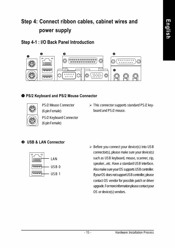
Step 4-1 : I/O Back Panel Introduction
PS/2 Keyboard and PS/2 Mouse Connector
This connector supports standard PS/2 key-board and PS/2 mouse.
USB & LAN ConnectorBefore you connect your device(s) into USBconnector(s), please make sure your device(s)such as USB keyboard, mouse, scanner, zip,speaker...etc. Have a standard USB interface.Also make sure your OS supports USB controller.If your OS does not support USB controller, pleasecontact OS vendor for possible patch or driverupgrade. For more information please contact yourOS or device(s) vendors.
PS/2 Mouse Connector(6 pin Female)
PS/2 Keyboard Connector(6 pin Female)
USB 0
USB 1
LAN

- 16 -GA-7VKMP Series Motherboard
Engl
ish Parallel Port and VGA Port / COMA Port
Parallel Port(25 pin Female)
This motherboard sutports 1 standard COMport,1 VGA port and 1 LPT port. Device likeprinter can be connected to LPT port; mouseand modem etc. can be connected to COMport.
COMA VGA
Game / MIDI Ports
Joystick/ MIDI (15 pin Female)
This connector supports joystick, MIDI keyboardand other relate audio devices.
Audio ConnectorsAfter install onboard audio driver, you may con-nect speaker to Line Out jack, microphone toMIC In jack. Device like CD-ROM,walkmanetc. can be connected to Line-In jack.Please note: ( )
You are able to use 2-/4-/6-channel audio fea-ture by S/W selection.If you want to enable 6-channel function, youhave 2 choose for hardware connection.Method1:Connect "Front Speaker" to "Line Out"Connect "Rear Speaker" to "Line In"Connect "Center and Subwoofer" to "MIC Out ".Method2:You can refer to page 21, and contact yournearest dealer for optional SUR_CEN cable.
Serial Port(9 pin Male)
VGA Port(15 pin Female)
MIC In(Center and Subwoofer( ))
Line Out(Front Speaker( ))
Line In(Rear Speaker ( ) )
** Only for GA-7VKMP-SI.
For GA-7VKMP only. For GA-7VKMP-P only. For GA-7VKMP-SI only.
If you want the detail information for 2-/4-/6-channel audio setupinstallation, please refer to page 60.

- 17 - Hardware Installation Process
English
Step 4-2 : Connectors Introduction
For GA-7VKMP only. For GA-7VKMP-P only. For GA-7VKMP-SI only.
3
5
20
7
1
8
10
2
11 17
9
4
14 ( ) 19
6
16
1) CPU_FAN2) SYS_FAN3) ATX4) FDD5) IDE1 / IDE26) RAM_LED7) F_PANEL8) PWR_LED9) F_AUDIO
10) AUX_IN
11) CD_IN12) SUR_CEN ( )
13) SPDIF ( )
14) SPDIF_IN ( )
15) IR16) COMB17) F_USB1 / F_USB218) S_IRQ ( )
19) BATTERY20) CI
12( )
13( )
18( )15

- 18 -GA-7VKMP Series Motherboard
Engl
ish 1) CPU_FAN (CPU Fan Connector) Please note, a proper installation of the CPU
cooler is essential to prevent the CPU fromrunning under abnormal condition or damagedby overheating. The CPU fan connectorsupports Max. current up to 600 mA.
1
+12V/ControlGND Sense
2) SYS_FAN (System Fan Connector) This connector allows you to link with thecooling fan on the system case to lower thesystem temperature.
1
+12V/ControlGND Sense
3) ATX (ATX Power) AC power cord should only be connected toyour power supply unit after ATX power cableand other related devices are firmly connectedto the motherboard.
PS-ON(Soft On/Off)
3.3V3.3V
GND
GND
GND
VCC
VCC
+12V
5V SB (Stand by +5V)Power Good
3.3V
GND
GND
GNDGND
VCC
VCC
-12V
1
20
-5V

- 19 - Hardware Installation Process
English
4) FDD (Floppy Connector) Please connect the floppy drive ribbon cablesto FDD. It supports 360K, 1.2M, 720K, 1.44Mand 2.88M bytes floppy disk types.The red stripe of the ribbon cable must be thesame side with the Pin1.
FDD
1
5) IDE1 / IDE2 (IDE1 / IDE2 Connector)
IDE1
1
IDE2
1
Important Notice:Please connect first hard disk to IDE1 andconnect CD-ROM to IDE2.The red stripe of the ribbon cable must be thesame side with the Pin1.
6) RAM_LED Do not remove memory modules whileDIMM LED is on. It might cause short or otherunexpected damages due to the 2.5V standby voltage. Remove memory modules onlywhen AC Power cord is disconnected.
+_

- 20 -GA-7VKMP Series Motherboard
Engl
ish 7) F_PANEL (2x10 pins connector)
Please connect the power LED, PC speaker, reset switch and power switch etc. of yourchassis front panel to the F_PANEL connector according to the pin assignment above.
SPK+
GN (Green Switch) Open: Normal OperationClose: Entering Green Mode
GD (Green LED) Pin 1: LED anode(+)Pin 2: LED cathode(-)
HD (IDE Hard Disk Active LED) Pin 1: LED anode(+)Pin 2: LED cathode(-)
SPK (Speaker Connector) Pin 1: VCC(+)Pin 2- Pin 3: NCPin 4: Data(-)
RST (Reset Switch) Open: Normal OperationClose: Reset Hardware System
PW (Soft Power Connector) Open: Normal OperationClose: Power On/Off
MPD (Message LED/Power/ Pin 1: LED anode(+)Sleep LED) Pin 2: LED cathode(-)N C N C
NC
HD+
MPD
+
2 20
1 19
GD-
PW-
PW+
RST-
SPK-
1
RST+HD
-
GD+1
MPD
-
GN-
GN+
NC
1 1
111 NC
8) PWR_LED
MPD+MPD-
MPD-
1
PWR_LED is connect with the system powerindicator to indicate whether the system ison/off. It will blink when the system enterssuspend mode.If you use dual color LED, Power LED willturn to another color.

- 21 - Hardware Installation Process
English
9) F_AUDIO (Front Audio Connector) If you want to use Front Audio connector, youmust remove 5-6, 9-10 Jumper. In order toutilize the front audio header, your chassis musthave front audio connector. Also please makesure the pin assigment on the cable is the sameas the pin assigment on the MB header. To findout if the chassis you are buying support frontaudio connector, please contact your dealer.
Front Audio (L)
1
Reserved
GND
Rear Audio (R)
Rear Audio (L)
Front Audio (R)
2
910
MICREFPOWER
For GA-7VKMP only. For GA-7VKMP-P only. For GA-7VKMP-SI only.
11) CD_IN (CD In Connector)
1
CD-LCD-RGND
10) AUX_IN (AUX In Connector)
1
AUX-R
AUX-LGND
Connect CD-ROM or DVD-ROM audio out tothe connector.
Connect other device (such as PCI TV Tunneraudio out) to the connector.
12) SUR_CEN (Surround Center Connector)( )
Please contact your nearest dealer for optionalSUR_CEN cable.
SUR OUT(R) SUR OUT(L)GNDCENTER_OUTBASS_OUT
12

- 22 -GA-7VKMP Series Motherboard
Engl
ish
For GA-7VKMP only. For GA-7VKMP-P only. For GA-7VKMP-SI only.
15) IRBe careful with the polarity of the IR connector.Check the pin assignment carefully while youconnect the IR cable, incorrect connectionbetween the cable and connector will make thedevice unable to work or even damage it. Foroptional IR cable, please contact your localdealer.
13) SPDIF (SPDIF Out) ( ) The SPDIF output is capable of providingd i g i t a l a u d i o t o e x t e r n a l s p e a k e r s o rcompressed AC3 data to an external DolbyDigital Decoder. Use this feature only whenyour stereo system has digital input function.6 Channel output : A "S/PDIF output" connectoris available on the motherboard. Be carefulwith the polarity of the SPDIF out connector.Check the pin assignment carefully while youconnect the SPDIF out cable, incorrect connec-tion between the cable and connector will makethe device unable to work or even damage it.For optional SPDIF out cable, please contactyour local dealer.
SPDIF Out
GND
1
VCC
16) COMB (COMB Port)
Be careful with the polarity of the COMBconnector. Check the pin assignment carefullywhile you connect the COMB cable, incorrectconnection between the cable and connectorwill make the device unable to work or evendamage it. For optional COMB cable, pleasecontact your local dealer.
RXD2DTR2
DSR2CTS2
N C
DCD2TXD2
GNDRTS2
RI2 9 10
1 2
VCC(+5V)IR Data Input
GND
IR Data Output
1
14) SPDIF_IN (SPDIF In)( ) Use this feature only when your device hasdigital output function. Be careful with the polar-ity of the SPDIF in connector. Check the pinassignment carefully while you connect theSPDIF in cable, incorrect connection betweenthe cable and connector will make the deviceunable to work or even damage it. For optionalSPDIF in cable, please contact your local dealer.SPDIF In
GND
1
VCC
- 23 - Hardware Installation Process
English
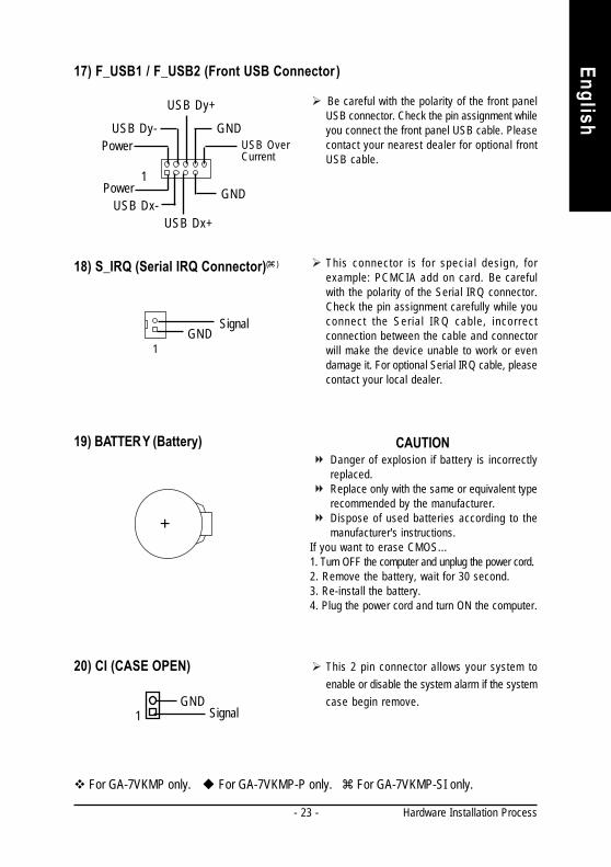
19) BATTERY (Battery) CAUTIONDanger of explosion if battery is incorrectlyreplaced.Replace only with the same or equivalent typerecommended by the manufacturer.Dispose of used batteries according to themanufacturer's instructions.
If you want to erase CMOS...1. Turn OFF the computer and unplug the power cord.2. Remove the battery, wait for 30 second.3. Re-install the battery.4. Plug the power cord and turn ON the computer.
For GA-7VKMP only. For GA-7VKMP-P only. For GA-7VKMP-SI only.
20) CI (CASE OPEN)
SignalGND
This 2 pin connector allows your system toenable or disable the system alarm if the systemcase begin remove.
1
18) S_IRQ (Serial IRQ Connector)( )
SignalGND
This connector is for special design, forexample: PCMCIA add on card. Be carefulwith the polarity of the Serial IRQ connector.Check the pin assignment carefully while youconnect the Ser ia l IRQ cable, incorrectconnection between the cable and connectorwill make the device unable to work or evendamage it. For optional Serial IRQ cable, pleasecontact your local dealer.
1
+
Be careful with the polarity of the front panelUSB connector. Check the pin assignment whileyou connect the front panel USB cable. Pleasecontact your nearest dealer for optional frontUSB cable.
17) F_USB1 / F_USB2 (Front USB Connector )
USB Dy-
Power
USB Dx+
1
USB Dy+
USB OverCurrent
PowerGND
GNDUSB Dx-

- 24 -GA-7VKMP Series Motherboard
Engl
ish

- 25 - BIOS Setup
English
Chapter 3 BIOS Setup
< > Move to prev ious item
< > Move to next item
< > Move to the item in the left hand
< > Move to the item in the right hand
<Enter> Select Item
<Esc> Main Menu - Quit and not save changes into CMOS Status Page Setup Menu andOption Page Setup Menu - Ex it current page and return to Main Menu
<+/PgUp> Increase the numeric value or make changes
<-/PgDn> Decrease the numeric value or make changes
<F1> General help, only for Status Page Setup Menu and Option Page Setup Menu
<F2> Item Help
<F3> Reserved
<F4> Reserved
<F5> Restore the prev ious CMOS value from CMOS, only for Option Page Setup Menu
<F6> Load the file-safe default CMOS value from BIOS default table
<F7> Load the Optimized Defaults
<F8> Q-Flash function
<F9> Reserved
<F10> Save all the CMOS changes, only for Main Menu
BIOS Setup is an overv iew of the BIOS Setup Program. The program that allows users to modify thebasic system configuration. This type of information is stored in battery-backed CMOS RAM so that itretains the Setup information when the power is turned off.
ENTERINGPowering ON the computer and pressing <Del> immediately will allow you to enter Setup. If you requiremore advanced BIOS settings, please go to "Advanced BIOS" setting menu. To enter Advanced BIOSsetting menu, press "Ctrl+F1" key on the BIOS screen.
CONTROL
SETUP
KEYS

- 26 -GA-7VKMP Series Motherboard
Engl
ish
l Standard CMOS SetupThis setup page includes all the items in standard compatible BIOS.
l BIOS Features SetupThis setup page includes all the adjustable items of AMI special enhanced features.
l Chipset Features SetupThis setup page includes all the adjustable items of chipset special features.
GETTING HELPMain Menu
The on-line description of the highlighted setup function is displayed at the bottom of the screen.
Status Page Setup Menu / Option Page Setup MenuPress F1 to pop up a small help window that describes the appropriate keys to use and the possibleselections for the highlighted item. To ex it the Help Window press <Esc>.
The Main Menu (For example: BIOS Ver. : F1h)Once you enter AMI BIOS CMOS Setup Utility, the Main Menu (Figure 1) will appear on the screen.The Main Menu allows you to select from eight setup functions and two ex it choices. Use arrow keys toselect among the items and press <Enter> to accept or enter the sub-menu.
Figure 1: Main Menu
AMIBIOS SIMPLE SETUP UTILITY - VERSION 2.00
(C) 2001 American Megatrends, Inc. All Rights Reserv ed
STANDARD CMOS SETUP INTEGRATED PERIPHERALS
BIOS FEATURES SETUP HARDWARE MONITOR & MISC SETUP
CHIPSET FEATURES SETUP SUPERVISOR PASSWORD
POWER MANAGEMENT SETUP USER PASSWORD
PNP / PCI CONFIGURATION IDE HDD AUTO DETECTION
LOAD FAIL-SAFE DEFAULTS SAVE & EXIT SETUP
LOAD OPTIMIZED DEFAULTS EXIT WITHOUT SAVING
ESC: Quit hifg: Select Item F5: Old Values F6: Fail-Safe Values
F7: Optimized Values F8: Q-Flash Utility F10:Sav e & Ex it
Time, Date, Hard Disk Ty pe...
- 27 - BIOS Setup
English
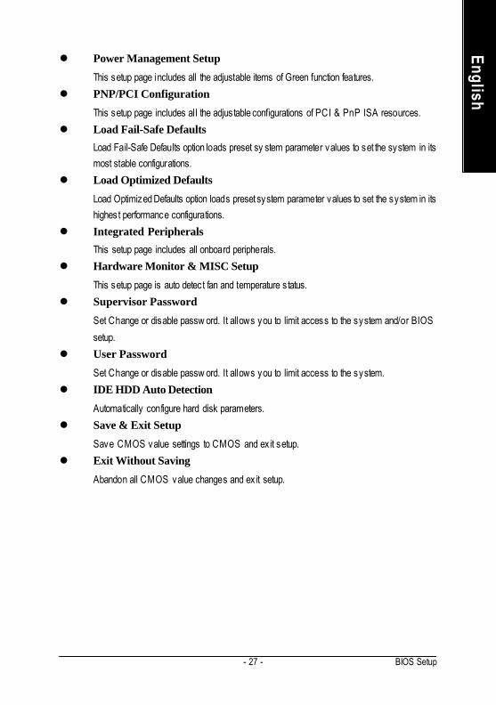
l Power Management SetupThis setup page includes all the adjustable items of Green function features.
l PNP/PCI ConfigurationThis setup page includes all the adjustable configurations of PCI & PnP ISA resources.
l Load Fail-Safe DefaultsLoad Fail-Safe Defaults option loads preset sy stem parameter values to set the system in itsmost stable configurations.
l Load Optimized DefaultsLoad Optimized Defaults option loads preset system parameter values to set the system in itshighest performance configurations.
l Integrated PeripheralsThis setup page includes all onboard peripherals.
l Hardware Monitor & MISC SetupThis setup page is auto detect fan and temperature s tatus.
l Supervisor PasswordSet Change or disable passw ord. It allows you to limit access to the system and/or BIOS
setup.
l User PasswordSet Change or disable passw ord. It allows you to limit access to the system.
l IDE HDD Auto DetectionAutomatically configure hard disk parameters.
l Save & Exit SetupSave CMOS value settings to CMOS and ex it setup.
l Exit Without SavingAbandon all CMOS value changes and ex it setup.

- 28 -GA-7VKMP Series Motherboard
Engl
ish Standard CMOS Features
DateThe date format is <week> , <month>, <day>, <y ear>.
Week The w eek, from Sun to Sat, determined by the BIOS and is display only
Month The m onth, Jan. Through Dec.
Day The day , from 1 to 31 (or the max imum allow ed in the m onth)
Year The y ear, from 1990 through 2099
TimeThe times format in <hour> <minute> <second> . The time is calculated base on the 24-hour
military time clock. For ex ample, 1 p.m. is 13:00:00.
Figure 2: Standard CMOS Setup
AMIBIOS SETUP - STANDARD CMOS SETUP
( C ) 2001 American Megatrends, Inc. All Rights Reserv ed
Sy stem Date : Jul 01 2002 Mon
Sy stem Time : 16:10:49
TYPE SIZE CYLS HEAD PRECOMP LANDZ SECTOR MODE
Pri Master : Auto
Pri Slav e : Auto
Sec Master : Auto
Sec Slav e : Auto
Floppy Driv e A : 1.44 MB 31/2 Base Memory : 640 Kb
Floppy Driv e B : Not Installed Other Memory : 384 Kb
Ex tended Memory : 127 Mb
Virus Protection : Disabled Total Memory : 128 Mb
Date is standard format ESC : Ex it
Month : Jan - Dec hi : Select Item
Day : 01- 31 PU / PD / + / - :Modify
Year : 1990 - 2099 (Shift) F2 : Color
- 29 - BIOS Setup
English
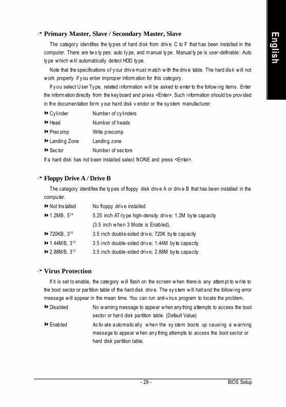
Primary Master, Slave / Secondary Master, SlaveThe category identifies the ty pes of hard disk from driv e C to F that has been insta lled in the
computer. There are tw o ty pes: auto ty pe, and m anual ty pe. Manual ty pe is user-definable; Autoty pe w hich w il l automatically detect HDD ty pe.
Note that the specifications of y our driv e must m atch w ith the driv e table. The hard dis k w ill notw ork properly if y ou enter improper inform ation for this category .
If y ou select U ser Ty pe, related information w ill be asked to enter to the follow ing items. Enterthe inform ation directly from the key board and press <Enter>. Such information should be prov ided
in the documentation form y our hard disk v endor or the sy stem manufacturer.
Cy linder Number of cy linders
Head Number of heads
Prec omp Write precomp
Landing Zone Landing zone
Sec tor Number of sec tors
If a hard disk has not been instal led select NONE and press <Enter>.
Floppy Drive A / Drive BThe category identi fies the ty pes of floppy disk driv e A or driv e B that has been installed in the
computer.
Not Ins talled No floppy driv e insta lled
1.2MB, 51/4 5.25 inch AT-ty pe high-density dr iv e; 1.2M by te capacity
(3.5 inch w hen 3 Mode is Enabled).
720KB, 31/2 3.5 inch double-sided dr iv e; 720K by te capacity
1.44M B, 31/2 3.5 inch double-sided driv e; 1.44M by te capacity .
2.88M B, 31/2 3.5 inch double-sided driv e; 2.88M by te capacity .
Virus ProtectionIf it is set to enable, the category w ill flash on the screen w hen there is any attem pt to w ri te to
the boot sector or par tition table of the hard disk driv e. The sy s tem w ill halt and the follow ing errormessage w ill appear in the mean time. You can run anti-v irus program to locate the problem.
Disabled No w arning message to appear w hen any thing attempts to access the bootsector or hard disk partition table. (Default Value)
Enabled Ac tiv ate automatic ally w hen the sy stem boots up causing a w arningmessage to appear w hen any thing attempts to access the boot sector orhard disk par tition table.
- 30 -GA-7VKMP Series Motherboard
Engl
ish Memory
The category is display-only which is determined by POS T (Power On Self Test) of the BIOS.
-- Base MemoryThe POST of the BIOS w ill determine the amount of base (or conv entional) m emory installedin the sy stem.
The v alue of the base memory is ty pically 512K for s y stems w i th 512K memory installedon the motherboard, or 640K for s y stems w ith 640 K or more m emory instal led on themotherboard.
-- Other MemoryThis refers to the memory located in the 640K to 1024K address space. This is memory thatcan be used for different applications.
DOS uses this area to load dev ice driv ers to keep as much base memory free for applicationprograms. Most use for this area is Shadow RAM.
-- Extended MemoryThe BIOS determines how much ex tended memory is present during the POST.
This is the am ount of memory located abov e 1MB in the CPU 's memory address map.

- 31 - BIOS Setup
English
BIOS Features Setup AMIBIOS SETUP - BIOS FEATURES SETUP
( C ) 2001 American Megatrends, Inc. All Rights Reserv ed
Figure 3: BIOS Features Setup
BIOS Flash ProtectionThis field lets y ou determine the states that flash BIOS.
Auto BIOS enables flash w rite access automatica lly w hen updating BIOS data/DMI/ESCD. (Default Value)
Enabled During POST, DMI/ESCD w ould not be updated. But flash tools can update BIOSalw ay s.
1st / 2nd / 3rd Boot DeviceDisabled Dis abled th is function.
Floppy : 1.44M B 31/2 Select y our boot dev ice prior ity by Floppy .
BBS-0(Netw ork ): Realtek Boot Agent Select y our boot dev ice priori ty by Netw ork.
IDE-0: ST320420A Select y our boot dev ice priority by IDE Dev ice.
USB RM D-FDD: Apacer Handy Driv e Select y our boot dev ice priority by USB Dev ice.
Boot order depends on the dev ices you use, for example: Floppy, HDD, CD-ROM...
BIOS F lash Protection : Auto
1st Boot Dev ice : Floppy
2nd Boot Dev ice : Disabled
3rd Boot Dev ice : Disabled
Floppy Driv e Seek : Disabled
BootUp Num-Lock : On
Passw ord Check : Setup
S.M. A.R.T. for Hard Disk : Disabled
Interrupt Mode : APIC
ESC: Quit hifg: Select Item
F1 : Help PU/PD/+/- : Modify
F5 : Old Values (Shift)F2: Color
F6 : Fail-Safe F7 : Optimized
F8 : Q-Flash Utility

- 32 -GA-7VKMP Series Motherboard
Engl
ish Floppy Drive Seek
During POST, BIOS w ill determine the floppy disk dr iv e insta lled is 80 tracks. 720K, 1.2M and1.44M are al l 80 tracks.
Enabled BIOS s earches for floppy disk driv e to determine it is 80 track s. Note that BIOScan not tell from 720K, 1.2M or 1.44M driv e ty pe as they are all 80 tracks.
Disabled BIOS w ill not search for the ty pe of floppy disk driv e by track number. N ote thatthere w ill not be any w arning message if the driv e ins talled is 360K.(Default v a lue)
BootUp Num-LockOff When bootup, setting key pad is arrow key s.
On When bootup, setting key pad is num ber key s. (Default v alue)
Password CheckPlease refer to the detail on page 49.
Setup The user must enter correct passw ord in order to ac cess BIOS setup uti lity .(Default Value)
Alw ay s The user must enter correct pass w ord in order to access the sy stem and/orBIOS Setup.
S.M.A.R.T. for Hard DisksEnabled Enable HDD S. M.A.R.T. Capabil ity .
Disabled Disable HDD S.M .A.R.T. Capability . (Default v alue)
APIC Interrupt ModeAPIC Through IOAPIC generate more IRQ for sy stem use. (Default Value)
PIC Use AT standard IRQ controllers to generate IRQ.
When y ou already hav e IOAPIC enable sy stem and w ant to upgrade the sy stem please note,since running an IOAPIC enabled OS (like Window s NT, Window s 2000, Window s XP...) sy stemw ith none IOAPIC HW support w ill cause the sy stem to hang. Follow ing are some situations usersmight run into: 1.An IOAPIC enabled OS and change the BIOS setting from IOAPIC to PIC, this w illcause y our sy stem to hang.

- 33 - BIOS Setup
English
Figure 4: Chipset Features Setup
Chipset Features Setup
Configure SDRAM by SPDDisabled Disable Configure SDRAM by SPD.
Enabled Enable Configure SDRAM by SPD. (Default Value)
SDRAM Frequency200MHz Set SDRAM Frequency to 200MHz.
266MHz Set SDRAM Frequency to 266MHz.
Auto Set SDRAM Frequency to Auto. (Default Value)
SDRAM CAS# LatencyThis item w ill be av ailable w hen "Configure SDRAM by SPD" set to Disabled.
2.5 For Slow er SDR AM DIMM m odule. (Default Value)
2 For F astest SDR AM DIMM module.
We would not suggest you change the chipset default setting unless you really need it.
AMIBIOS SETUP - CHIPSET FEATURES SETUP
( C ) 2001 American Megatrends, Inc. All Rights Reserv ed
Configure SDRAM by SPD : Enabled
SDRAM Frequency : Auto
SDRAM CAS# Latency : 2.5
SDRAM Command Rate : 2T Command
AGP Mode : 4X
AGP Comp. Driv ing : Auto
Manual AGP Comp. Driv ing : DA
AGP Fast Write : Disabled
AGP Aperture Size : 64MB
AGP Read Sy nchronization : Disabled
PCI Delay Transaction : Disabled
USB Controller : 6 USB Ports
USB 1.1 Legacy Support : Disabled
USB 1.1 64/60 Emulation : Disabled
ESC : Quit hifg : Select Item
F1 : Help PU/PD/+/- : Modify
F5 : Old Values (Shift)F2 : Color
F6 : Fail-Safe F7 : Optimized
F8 : Q-Flash Utility
- 34 -GA-7VKMP Series Motherboard
Engl
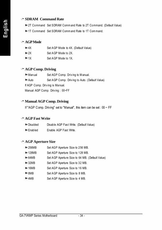
ish SDRAM Command Rate
2T Command Set SDRAM Comm and Rate to 2T Command. (Default Value)
1T Command Set SDRAM Comm and Rate to 1T Com mand.
AGP Mode4X Set AGP Mode to 4X. (Default Value)
2X Set AGP Mode to 2X.
1X Set AGP Mode to 1X.
AGP Comp. DrivingManual Set AGP Comp. Dr iv ing to M anual.
Auto Set AGP Comp. Driv ing to Auto. (Default Value)
If AGP Comp. Driv ing is Manual.
Manual AGP Comp. Driv ing : 00~FF
Manual AGP Comp. DrivingIf "AGP Comp. Driv ing" set to "Manual", this item can be set : 00 ~ FF
AGP Fast WriteDisabled Disable AGP Fas t Write. (Default Value)
Enabled Enable AGP Fast Write.
AGP Aperture Size256MB Set AGP Aperture Size to 256 MB.
128MB Set AGP Aperture Size to 128 MB.
64MB Set AGP Aperture Size to 64 MB. (Default Value)
32MB Set AGP Aperture Size to 32 MB.
16MB Set AGP Aperture Size to 16 MB.
8MB Set AGP Aperture Size to 8 MB.
4MB Set AGP Aperture Size to 4 MB.
- 35 - BIOS Setup
English
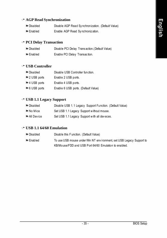
AGP Read SynchronizationDisabled Disable AGP Read Sy nchronization. (Default Value)
Enabled Enable AGP Read Sy nchroniz ation.
PCI Delay TransactionDisabled Disable PCI Delay Trans action.(Default Value)
Enabled Enable PCI Delay Transac tion.
USB ControllerDisabled Disable USB Controller function.
2 USB ports Enable 2 USB ports.
4 USB ports Enable 4 USB ports.
6 USB ports Enable 6 USB ports. (Default Value)
USB 1.1 Legacy SupportDisabled Disable USB 1. 1 Legacy Support Function. (Default Value)
No M ice Set USB 1.1 Legacy Support w ithout mouse.
All Dev ice Set USB 1.1 Legacy Support w ith all dev eces.
USB 1.1 64/60 EmulationDisabled Disable this F unction. (Default Value)
Enabled To use USB mouse under Win NT env i ronment, set USB Legacy Support to
KB/Mouse/FDD and USB Port 64/60 Emulation to enabled.

- 36 -GA-7VKMP Series Motherboard
Engl
ish Power Management Setup
Figure 5: Pow er Management Setup
ACPI Standby StateS1/ POS Set ACPI standby state to S1. (Default Value)
S3/ STR Set ACPI standby state to S3.
Power LED in S1 stateBlinking In standby mode(S1), pow er LED w il l blink. (Default Value)
Dual /OFF In standby mode(S1):
a. If use single color LED, pow er LED w ill turn off.
b. If use dual color LED, pow er LED w ill turn to another c olor.
AMIBIOS SETUP - POWER MANAGEMENT SETUP
( C ) 2001 American Megatrends, Inc. All Rights Reserv ed
ACPI Standby State : S1/POS
Pow er LED in S1 State : Blinking
USB Dev . Wakeup F rom S3 : Dis abled
Suspend Time Out (Min.) : Dis abled
IRQ 3 : Monitor
IRQ 4 : Monitor
IRQ 5 : Ignore
IRQ 7 : Monitor
IRQ 9 : Ignore
IRQ 10 : Ignore
IRQ 11 : Ignore
IRQ 13 : Ignore
IRQ 14 : Monitor
IRQ 15 : Ignore
Soft-Off by Pow er Button : Instant off
AC Back Func tion : Soft-Off
Modem Ring/Wake On Lan : Enabled
PME Ev ent Wak e Up : Enabled
Key board Wakeup From : S1(Suspend)
PS/2 M ouse Wakeup From : S1(Suspend)
ESC: Quit hifg: Select Item
F1 : Help PU/PD/+/- : Modify
F5 : Old Values (Shift)F2: Color
F6 : Fail-Safe F7 : Optimized
F8 : Q-Flash Utility
Resum e On RTC Alarm : Dis abled
RTC Alarm Date : 15
RTC Alarm Hour : 12
RTC Alarm Minute : 30
RTC Alarm Second : 30
- 37 - BIOS Setup
English
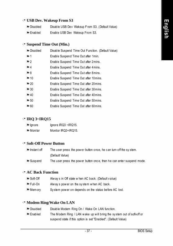
USB Dev. Wakeup From S3Disabled Disable USB Dev Wakeup F rom S3. (Default Value)
Enabled Enable USB Dev Wakeup From S3.
Suspend Time Out (Min.)Disabled Disable Suspend Time Out Function. (Default Value)
1 Enable Suspend Time Out after 1min.
2 Enable Suspend Time Out after 2mins.
4 Enable Suspend Time Out after 4mins.
8 Enable Suspend Time Out after 8mins.
10 Enable Suspend Time Out after 10mins.
20 Enable Suspend Time Out after 20mins.
30 Enable Suspend Time Out after 30mins.
40 Enable Suspend Time Out after 40mins.
50 Enable Suspend Time Out after 50mins.
60 Enable Suspend Time Out after 60mins.
IRQ 3~IRQ15Ignore Ignore IRQ3 ~IRQ15.
Moni tor Monitor IRQ3~IRQ15.
Soft-Off Power ButtonInstant off The user press the pow er button once, he c an turn off the sy stem.
(Default Value)
Suspend The user press the pow er button onc e, then he can enter suspend mode.
AC Back FunctionSoft-Off Alw ay s in Off state w hen AC back. (Default v a lue)
Full -On Alw ay s pow er on the sy stem w hen AC back.
Mem ory Sy stem pow er on depends on the status before AC lost.
Modem Ring/Wake On LANDisabled Disable Modem Ring On / Wake On LAN func tion.
Enabled The M odem Ring / LAN w ake up w ill bring the sy stem out of soft-o ff orsuspend state if this option is set "Enabled". (Default Value)
- 38 -GA-7VKMP Series Motherboard
Engl
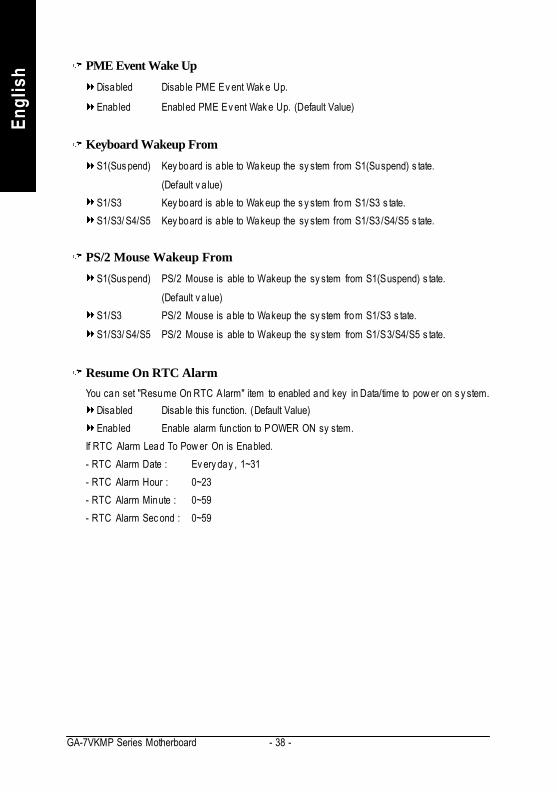
ish PME Event Wake Up
Disabled Disable PME Ev ent Wak e Up.
Enabled Enabled PME Ev ent Wak e Up. (Default Value)
Keyboard Wakeup FromS1(Sus pend) Key board is able to Wakeup the sy stem from S1(Suspend) s tate.
(Default v a lue)
S1/S3 Key board is ab le to Wak eup the s y stem from S1/S3 s tate.
S1/S3/ S4/S5 Key board is able to Wakeup the sy stem from S1/S3/S4/S5 s tate.
PS/2 Mouse Wakeup FromS1(Sus pend) PS/2 Mouse is able to Wakeup the sy stem from S1(Suspend) s tate.
(Default v a lue)
S1/S3 PS/2 Mouse is able to Wakeup the sy stem from S1/S3 s tate.
S1/S3/ S4/S5 PS/2 Mouse is able to Wakeup the sy stem from S1/S3/S4/S5 s tate.
Resume On RTC AlarmYou can set "Resume On RTC Alarm" item to enabled and key in Data/time to pow er on s y stem.
Disabled Disable this function. (Default Value)
Enabled Enable alarm function to POWER ON sy stem.
If RTC Alarm Lead To Pow er On is Enabled.
- RTC Alarm Date : Ev ery day , 1~31
- RTC Alarm Hour : 0~23
- RTC Alarm Minute : 0~59
- RTC Alarm Sec ond : 0~59

- 39 - BIOS Setup
English
PNP/PCI Configuration
Figure 6: PNP/PCI Configuration
OnChip VGA Frame BufferNone Disable this function.
8MB Set OnChip VGA Frame Buffer to 8MB.
16MB Set OnChip VGA Frame Buffer to 16MB.
32MB Set OnChip VGA Frame Buffer to 32MB. (Default Value)
VGA Boot FromPCI Set VGA Boot from PCI VGA Card.
AGP Set VGA Boot from AGP VGA Card. (Default Value)
AMIBIOS SETUP - PNP/PCI CONFIGURATION
( C ) 2001 American Megatrends, Inc. All Rights Reserv ed
OnChip VGA Frame Buffer : 32MB
VGA Boot From : AGP
PCI Slot 1 IRQ Pr iority : Auto
PCI Slot 2 IRQ Pr iority : Auto
PCI Slot 3 IRQ Pr iority : Auto
Realtek LAN ROM initial : Yes
ESC: Quit hifg: Select Item
F1 : Help PU/PD/+/- : Modify
F5 : Old Values (Shift)F2: Color
F6 : Fail-Safe F7 : Optimized
F8 : Q-Flash Utility

- 40 -GA-7VKMP Series Motherboard
Engl
ish PCI Slot 1, 2, 3 IRQ Priority
Auto The sy stem w ill reserv ed a free IRQ for PCI slot 1, 2, 3 dev ice. (Default Value)
3 The s y stem w i ll reserv ed IRQ3 for PCI s lot 1, 2, 3 dev ice if no legacyISA dev ice using IRQ3.
4 The s y stem w i ll reserv ed IRQ4 for PCI s lot 1, 2, 3 dev ice if no legacyISA dev ice using IRQ4.
5 The s y stem w i ll reserv ed IRQ5 for PCI s lot 1, 2, 3 dev ice if no legacyISA dev ice using IRQ5.
7 The s y stem w i ll reserv ed IRQ7 for PCI s lot 1, 2, 3 dev ice if no legacyISA dev ice using IRQ7.
10 The s y stem w il l reserv ed IRQ10 for PCI s lot 1, 2, 3 dev ic e if no legacyISA dev ice using IRQ10.
111 The s y stem w il l reserv ed IRQ11 for PCI s lot 1, 2, 3 dev ic e if no legacyISA dev ice using IRQ11.
Realtek LAN ROM initialNo Disable Realtek LAN ROM in itial.
Yes Enable Realtek LAN ROM initial. (Default Value)

- 41 - BIOS Setup
English
Load Fail-Safe DefaultsAMIBIOS SIMPLE SETUP UTILITY - VERSION 2.00
(C) 2001 American Megatrends, Inc. All Rights Reserv ed
STANDARD CMOS SETUP INTEGRATED PERIPHERALS
BIOS FEATURES SETUP HARDWARE MONITOR & MISC SETUP
CHIPSET FEATURES SETUP SUPERVISOR PASSWORD
POWER MANAGEMENT SETUP USER PASSWORD
PNP / PCI CONFIGURATION IDE HDD AUTO DETECTION
LOAD FAIL-SAFE DEFAULTS SAVE & EXIT SETUP
LOAD OPTIMIZED DEFAULTS EXIT WITHOUT SAVING
ESC: Quit hifg: Select Item F5: Old Values F6: Fail-Safe Values
F7: Optimized Values F8: Q-Flash Utility F10:Sav e & Ex it
Load Fail-Safe Defaults
Figure 7: Load Fail-Safe Defaults
Load Fail-Safe DefaultsFail-S afe defaults contain the most appropriate system parameter values of to configurethe system to achieve max imum stability .
Load Fail-Safe Defaults (Y/N) ? N

- 42 -GA-7VKMP Series Motherboard
Engl
ish Load Optimized Defaults
AMIBIOS SIMPLE SETUP UTILITY - VERSION 2.00
(C) 2001 American Megatrends, Inc. All Rights Reserv ed
STANDARD CMOS SETUP INTEGRATED PERIPHERALS
BIOS FEATURES SETUP HARDWARE MONITOR & MISC SETUP
CHIPSET FEATURES SETUP SUPERVISOR PASSWORD
POWER MANAGEMENT SETUP USER PASSWORD
PNP / PCI CONFIGURATION IDE HDD AUTO DETECTION
LOAD FAIL-SAFE DEFAULTS SAVE & EXIT SETUP
LOAD OPTIMIZED DEFAULTS EXIT WITHOUT SAVING
ESC: Quit hifg: Select Item F5: Old Values F6: Fail-Safe Values
F7: Optimized Values F8: Q-Flash Utility F10:Sav e & Ex it
Load Optimized Defaults
Figure 8: Load Optimized Defaults
Load Optimized DefaultsOptimized defaults contain the most appropriate system parameter values to configurethe s y stem to achiev e max imum perform ance.
Load Optimized Defaults (Y/N) ? N

- 43 - BIOS Setup
English
Integrated Peripherals
Figure 9: Integrated Peripherals
OnBoard IDEDisabled Disable OnBoard IDE.
Prim ary Only Primary IDE channel is enabled.
Secondary Only Secondary IDE channel is enabled.
Both Both Primary & Secondary IDE channel w ill be enabled. (Default Value)
AMIBIOS SETUP - INTEGRATED PERIPHERALS
( C ) 2001 American Megatrends, Inc. All Rights Reserv ed
OnBoard IDE : Both
IDE1 Conductor Cable : Auto
IDE2 Conductor Cable : Auto
OnBoard FDC : Auto
OnBoard Serial Port 1 : Auto
OnBoard Serial Port 2 : Auto
Serial Port2 Mode : Normal
OnBoard Parallel Port : Auto
Parallel Port Mode : ECP
Parallel Por t IRQ : Auto
Parallel Por t DMA : Auto
OnBoard MIDI Port : 300
MIDI Port IRQ : 5
OnBoard Game Port : 201
OnBoard AC’97 Audio : Auto
Onboard Lan Chip : Enabled
ESC: Quit hifg: Select Item
F1 : Help PU/PD/+/- : Modify
F5 : Old Values (Shift)F2: Color
F6 : Fail-Safe F7 : Optimized
F8 : Q-Flash Utility

- 44 -GA-7VKMP Series Motherboard
Engl
ish IDE1 Conductor Cable
Auto Will be automatically detected by BIOS. (Default Value)
ATA66/100/133 Set IDE1 Conduc tor Cable to ATA66/ 100/133 (Please mak e sure y our IDEdev ic e and cable is compatible w ith ATA66/100/133)
ATA33 Set IDE1 Conduc tor Cable to ATA33 (Please m ake sure y our IDE dev iceand cable is compatible w ith ATA33)
IDE2 Conductor CableAuto Will be automatically detected by BIOS. (Default Value)
ATA66/100/133 Set IDE1 Conductor Cable to ATA66/100. (Please make sure y our IDEdev ic e and cable is com patible w ith ATA66/100)
ATA33 Set IDE1 Conduc tor Cable to ATA33. (Please m ake sure y our IDE dev iceand cable is compatible w ith ATA33)
On Board FDCAuto Set On Board FDC to Auto. (Default Value)
Disabled Disable On Board FDC.
Enabled Enable On Board FDC.
Onboard Serial Port 1Auto BIOS w ill automatically setup the port 1 address. (Default Value)
Disabled Disable onboard Serial port 1.
3F8/ COM1 Enable onboard Serial port 1 and address is 3F8.
2F8/ COM2 Enable onboard Serial port 1 and address is 2F8.
3E8/ COM3 Enable onboard Serial port 1 and address is 3E8.
2E8/ COM4 Enable onboard Serial port 1 and address is 2E8.
Onboard Serial Port 2Auto BIOS w ill automatically setup the port 2 address. (Default Value)
Disabled Disable onboard Serial port 2.
3F8/ COM1 Enable onboard Serial port 2 and address is 3F8.
2F8/ COM2 Enable onboard Serial port 2 and address is 2F8.
3E8/ COM3 Enable onboard Serial port 2 and address is 3E8.
2E8/ COM4 Enable onboard Serial port 2 and address is 2E8.

- 45 - BIOS Setup
English
Serial Port 2 ModeNormal Normal operation. (Default Value)
IrDA Onboard I/O chip supports IrDA.
ASKIR Onboard I/O chip supports ASKIR.
OnBoard Parallel portAuto Set On Board LPT port is Auto. (Default Value)
Disabled Disable On Board LPT port.
378 Enable On Board LPT port and address is 378.
278 Enable On Board LPT port and address is 278.
3BC Enable On Board LPT port and address is 3BC.
Parallel Port ModeNormal Normal Operation.
EPP Using Parallel port as Enhanced Parallel Port.
ECP Using Parallel port as Ex tended C apabilities Port. (Default Value)
EPP+ECP Using Parallel port as Enhanced Parallel Port & Ex tended Capabilities Port.
Parallel Port IRQAuto Set Auto to parallel Por t IRQ DMA Channel. (Default Value)
5 Set Parallel Port IRQ to 5.
7 Set Parallel Port IRQ to 7.
Parallel Port DMAAuto Set Auto to parallel port mode DMA Channel. (Default Value)
0 Set Parallel Port DMA to 0.
1 Set Parallel Port DMA to 1.
3 Set Parallel Port DMA to 3.
OnBoard MIDI PortDisabled Disable this function.
300 Set OnBoard MIDI Port to 300. (Default Value)
310 Set OnBoard MIDI Port to 310.
320 Set OnBoard MIDI Port to 320.
330 Set OnBoard MIDI Port to 330.

- 46 -GA-7VKMP Series Motherboard
Engl
ish MIDI Port IRQ
5 Set M IDI Port IRQ to 5. (Default Value)
10 Set MIDI Por t IRQ to 10.
111 Set MIDI Por t IRQ to 11.
OnBoard Game PortDisabled Disable this function.
201 Set game port at 201. (Default Value)
209 Set game port at 209. (Default Value)
OnBoard AC'97 AudioAuto Enable onboard AC'97 audio function. (Default Value)
Disabled Disable this function.
Onboard Lan ChipDisabled Disable this function.
Enabled Enable Onboard Lan Chip function. (Default Value)

- 47 - BIOS Setup
English
Hardware Monitor & MISC Setup
Figure 10: Hardw are Monitor & MISC Setup
Thermal Shut Down Temp.Disabled Norm al Function.
80°C / 176°F Set T heraml Shut Dow n tem perature at 80°C / 176°F.
85°C / 185°F Set T heraml Shut Dow n tem perature at 85°C / 185°F.
90°C / 194°F Set T heraml Shut Dow n tem perature at 90°C / 194°F.
95°C / 203°F Set T heraml Shut Dow n tem perature at 95°C / 203°F.
100°C / 212°F Set Theraml Shut Dow n temperature at 100°C / 212°F.
105°C / 221°F Set Theraml Shut Dow n temperature at 105°C / 221°F.
110°C / 230°F Set Theraml Shut Dow n temperature at 110°C / 230°F. (Default Value)
AMIBIOS SETUP - HARDWARE MONITOR & MISC SETUP
( C ) 2001 American Megatrends, Inc. All Rights Reserv ed
Thermal Shut Dow n Temp. : 110°C / 230°F
Reset Case Open Status : No
Case Status : Open
CPU Host Clock (Mhz) : 100
CPU Temp. : 35°C / 95°F
Sy stem Temp. : 33°C / 91°F
CPU Fan Speed : 7031 RPM
Sy stem Fan Speed : 0 RPM
Vcore : +1.760V
Vtt : +1.264V
+3.300V : +3.280V
+5.000V : +4.999V
+12.000V : +12.352V
5VSB : +4.999V
ESC: Quit hifg: Select Item
F1 : Help PU/PD/+/- : Modify
F5 : Old Values (Shift)F2: Color
F6 : Fail-Safe F7 : Optimized
F8 : Q-Flash Utility

- 48 -GA-7VKMP Series Motherboard
Engl
ish Reset Case Open Status
Case StatusIf the case is closed, "Case Status" w ill show "Closed".
If the cas e hav e been opened, "Case Status" w il l show "Open".
If y ou w ant to reset "Case Status" v alue, set "Reset Cas e Open Status"
to "Yes" and sav e C MOS, y our computer w ill res tart.
CPU Host Clock (Mhz)By Hw Set C PU Host C lock by Hw setup. (Default Value)
133 Set C PU Host C lock to 133MHz~200MHz.
100 Set C PU Host C lock to 100Mhz~167MHz.
CPU / System Temp.Detect CPU / Sy stem Temperature automatica lly..
CPU / System Fan SpeedDetec t CPU / Sy stem F an speed status automatic ally .
Current Voltage (V) Vcore / Vtt / +3.3V / +5V / +12V / 5VSBDetec t sy stem' s v oltage status automatic ally .

- 49 - BIOS Setup
English
Set Supervisor / User PasswordWhen you select this function, the following message will appear at the center of the screen to assist
you in creating a password.
AMIBIOS SIMPLE SETUP UTILITY - VERSION 2.00
(C) 2001 American Megatrends, Inc. All Rights Reserv ed
STANDARD CMOS SETUP INTEGRATED PERIPHERALS
BIOS FEATURES SETUP HARDWARE MONITOR & MISC SETUP
CHIPSET FEATURES SETUP SUPERVISOR PASSWORD
POWER MANAGEMENT SETUP USER PASSWORD
PNP / PCI CONFIGURATION IDE HDD AUTO DETECTION
LOAD FAIL-SAFE DEFAULTS SAVE & EXIT SETUP
LOAD OPTIMIZED DEFAULTS EXIT WITHOUT SAVING
ESC: Quit hifg: Select Item F5: Old Values F6: Fail-Safe Values
F7: Optimized Values F8: Q-Flash Utility F10:Sav e & Ex it
Change / Set / Disable Passw ord
Figure 11: Passw ord Setting
Type the password, up to six characters, and press <Enter>. You will be asked to confirm thepassword. Type the password again and press <Enter>. You may also press <Esc> to abort theselection and not enter a password.To disable password, just press <Enter> when you are prompted to enter password. A message"PASSWORD DISABLED" will appear to confirm the password being disabled. Once the passwordis disabled, the system will boot and you can enter Setup freely .The BIOS Setup program allows you to specify two separate passwords: a SUPERVISOR PASSWORD and a USER PASSWORD. When disabled, anyone may access all BIOS Setup programfunction. When enabled, the Superv isor password is required for entering the BIOS Setup program andhaving full configuration fields, the User password is required to access only basic items.If you select "Always" at "Password Check" in BIOS Features Setup Menu, you will beprompted for the password every time the system is rebooted or any time you try to enter SetupMenu.If you select "Setup" at "Password Check" in BIOS Features Setup Menu, you will be promptedonly when you try to enter Setup.
Enter new supervisor password:

- 50 -GA-7VKMP Series Motherboard
Engl
ish
AMIBIOS SETUP - STANDARD CMOS SETUP
( C ) 2001 American Megatrends, Inc. All Rights Reserv ed
Sy stem Date : Jul 01 2002 Mon
Sy stem Time : 16:10:49
TYPE SIZE CYLS HEAD PRECOMP LANDZ SECTOR MODE
Pri Master : Auto
Pri Slav e : Auto
Sec Master : Auto
Sec Slav e : Auto
Floppy Driv e A : 1.44 MB 31/2 Base Memory : 640 Kb
Floppy Driv e B : Not Installed Other Memory : 384 Kb
Ex tended Memory : 127 Mb
Virus Protection : Disabled Total Memory : 128 MbDate is standard format ESC : Ex it
Month : Jan - Dec hi : Select Item
Day : 01- 31 PU / PD / + / - :Modify
Year : 1990 - 2099 (Shift) F2 : Color
IDE HDD Auto Detection
Figure 12: IDE HDD Auto Detection
Type "Y" will accept the H.D.D. parameter reported by BIOS.Type "N" will keep the old H.D.D. parameter setup. If the hard disk cy linder number is over 1024, thenthe user can select LBA mode or LARGER mode for DOS partition larger than 528 MB.

- 51 - BIOS Setup
English
Save & Exit SetupAMIBIOS SIMPLE SETUP UTILITY - VERSION 2.00
(C) 2001 American Megatrends, Inc. All Rights Reserv ed
STANDARD CMOS SETUP INTEGRATED PERIPHERALS
BIOS FEATURES SETUP HARDWARE MONITOR & MISC SETUP
CHIPSET FEATURES SETUP SUPERVISOR PASSWORD
POWER MANAGEMENT SETUP USER PASSWORD
PNP / PCI CONFIGURATION IDE HDD AUTO DETECTION
LOAD FAIL-SAFE DEFAULTS SAVE & EXIT SETUP
LOAD OPTIMIZED DEFAULTS EXIT WITHOUT SAVING
ESC: Quit hifg: Select Item F5: Old Values F6: Fail-Safe Values
F7: Optimized Values F8: Q-Flash Utility F10:Sav e & Ex it
Sav e Data to CMOS & Ex it SETUP
Figure 13: Sav e & Ex it Setup
Type "Y" will quit the Setup Utility and save the user setup value to RTC CMOS.Type "N" will return to Setup Utility.
SAVE to CMOS and EXIT (Y/N) ? Y

- 52 -GA-7VKMP Series Motherboard
Engl
ish Exit Without Saving
Type "Y" will quit the Setup Utility without sav ing to RTC CMOS.Type "N" will return to Setup Utility.
AMIBIOS SIMPLE SETUP UTILITY - VERSION 2.00
(C) 2001 American Megatrends, Inc. All Rights Reserv ed
STANDARD CMOS SETUP INTEGRATED PERIPHERALS
BIOS FEATURES SETUP HARDWARE MONITOR & MISC SETUP
CHIPSET FEATURES SETUP SUPERVISOR PASSWORD
POWER MANAGEMENT SETUP USER PASSWORD
PNP / PCI CONFIGURATION IDE HDD AUTO DETECTION
LOAD FAIL-SAFE DEFAULTS SAVE & EXIT SETUP
LOAD OPTIMIZED DEFAULTS EXIT WITHOUT SAVING
ESC: Quit hifg: Select Item F5: Old Values F6: Fail-Safe Values
F7: Optimized Values F8: Q-Flash Utility F10:Sav e & Ex it
Abandon all Datas & Ex it SETUP
Figure 14: Ex it Without Sav ing
Quit without saving (Y/N) ? N

- 53 - BIOS Setup
English

- 54 -GA-7VKMP Series Motherboard
Engl
ish

Technical Reference- 55 -
English
Revision HistoryChapter 4 Technical Reference
Block Diagram
v For GA-7VKMP only . u For GA-7VKMP-P only . z For GA-7VKMP-SI only .
AMD-K7™
VIAKM266
VIAVT8235
CPU CLK (100/133MHz)
Host Bus 100/133MHz
2.5V DDR100/133 MHz
66 MHz14.318 MHz
48 MHz
PCI BUS
3 PCIRTL8100BL
RJ4
5
CODECReal tek ALC 101(v)
orReal tek ALC 650(uz)
MIC
LINE-IN
LINE-OUT
AGP 1X/2X/4X
AGPCLK(66MHz)
HCLK (100/133MHz)NPCLK (66MHz)
AGPCLK(66MHz)
ATA66/100/133IDE Channels
6 USBPorts
ITE 8705F
Gam
e Port
Floppy
LPT Port
PS/2 KB/M
ouse
2 COM
Ports
PCICLK(33MHz)
VGA Port
ICS950902DF
HCLK (66MHz)CPU CLK(100/133MHz)AGPCLK (66MHz)NPCLK (33MHz)
PCICLK (33MHz)USBCLK (48MHz)
14.318 MHz33 MHz

- 56 -GA-7VKMP Series Motherboard
Engl
ish Q-Flash Utility Introduction
A. What is Q-Flash Utility?Q-Flash utility is a pre-O.S. BIOS flash utility enables users to update its BIOS within BIOS
mode, no more fooling around any OS.
B. How to use Q-Flash?a. After power on the computer, pressing <Del> immediately during POST (Power On Self Test) it willallow you to enter A MI BIOS CMOS SETUP, then press <F8> to enter Flash utility.
b. Q-Flash Utility
Q-Flash Utility
Flash ROM Type.........................................SST 39SF020 256K
Enter: Run hi: Move ESC: Reset F10: Power Off
AMIBIOS SIMPLE SETUP UTILITY - VERSION 2.00
(C) 2001 American Megatrends, Inc. All Rights Reserv ed
STANDARD CMOS SETUP INTEGRATED PERIPHERALS
BIOS FEATURES SETUP HARDWARE MONITOR & MISC SETUP
CHIPSET FEATURES SETUP SUPERVISOR PASSWORD
POWER MANAGEMENT SETUP USER PASSWORD
PNP / PCI CONFIGURATION IDE HDD AUTO DETECTION
LOAD FAIL-SAFE DEFAULTS SAVE & EXIT SETUP
LOAD OPTIMIZED DEFAULTS EXIT WITHOUT SAVING
ESC: Quit hifg: Select Item F5: Old Values F6: Fail-Safe Values
F7: Optimized Values F8: Q-Flash Utility F10:Sav e & Ex it
Time, Date , Hard Disk Ty pe…
ENTER BIOS FLASH UTILITY (Y/N)? Y
Load BIOS from FloppySave BIOS to Floppy

Technical Reference- 57 -
English
Congratulation! You have completed the flashed and now can restart system.
Load BIOS From Floppy!In the A:drive, insert the "BIOS" diskette, then Press Enter to Run.
XXXX.XX 256K
Total Size: 1.39M Free Size: 1.14MF5: Refresh DEL: Delete
!Press Enter to Run.
1 File(s) found
Are you sure to update BIOS?[Enter] to contiune Or [ESC] ot abort...
!! COPY BIOS Completed -Pass !!Please press any key to continue
!Press Enter to Run.
Where XXXX.XX is name of the BIOS file.

- 58 -GA-7VKMP Series Motherboard
Engl
ish @BIOS™ Introduction
Gigabyte announces @BIOSWindows BIOS live update utility
Have y ou ever updated BIOS by yourself? O r likemany other people, you just know what BIOS is,but always hesitate to update it? Because you thinkupdating newest BIOS is unnecessary and actuallyyou don’t know how to update it.
Maybe not like others, you are very experienced in BIOS updating and spend quite a lot of time todo it. But of course you don’t like to do it too much. First, download different BIOS from website and thenswitch the operating system to DOS mode. Secondly , use different flash utility to update BIOS . Theabove process is not a interesting job. Besides, always be carefully to store the BIOS source codecorrectly in your disks as if you update the wrong BIOS , it will be a nightmare.
Certainly , you wonder w hy motherboard vendors could not just do something right to save yourtime and effort and save you from the lousy BIOS updating work? Here it comes! Now Gigabyteannounces @BIOS - the first Windows BIOS live update utility . This is a smart BIOS update software.It could help y ou to download the BIOS from internetand update it. Not like the other BIOS updatesoftware, it’s a Windows utility . With the help of “@BIOS’, BIOS updating is no more than a click.
Besides, no matter which mainboard you are using, if it’s a Gigabyte’s product* , @BIOS help youto maintain the BIOS. This utility could detect your correct mainboard model and help you to choose theBIOS accordingly . It then downloads the BIOS from the nearest Gigabyte ftp site automatically . Thereare several different choices; you could use “Internet Update” to download and update your BIOSdirectly . Or you may want to keep a backup for your current BIOS, just choose “Save Current BIOS”to save it first. You make a wise choice to use Gigabyte, and @BIOS update your BIOS smartly. Youare now worry free from updating wrong BIOS, and capable to maintain and manage y our B IOSeasily. Again, Gigabyte’s innovative product erects a milestone in mainboard industries.
For such a wonderful software, how much it costs? Impossible! It’s free! Now, if you buy aGigabyte’s motherboard, y ou could find this amazing software in the attached driver CD. But pleaseremember, connected to internet at first, then you could have a internet BIOS update from yourGigabyte @BIOS.

Technical Reference- 59 -
English
EasyTune™ 4 IntroductionGigabyte announces EasyTune™ 4Windows based Overclocking utilityEasyTune 4 carries on the heritage so as to pave the way for future generations.
Overclock" might be one of the most common is-sues in computer field. But hav e many users evertried it? The answer is probably " no" . Because"Overc lock" is thought to be very difficult and in-cludes a lot of technical know-how , sometimes"Overc lock" is even considered as special skil lsfound only in some enthusiasts. But as to the expertsin " Overclock", w hat's the truth? They may spendquite a lot of time and money to study, try and use
many different hardware or BIOS tools to do "Overclock". And even with these technologies, they stilllearn that it's quite a risk because the safety and stability of an "Ov erclock" system is unknown. Noweverything is different because of a Windows based overclocking utility "EasyTune 4" --announced byGigaby te. This windows based utility has totally changed the gaming rule of "Overclock". This is thefirst windows based overclocking utility is suitable for both normal and power users. Users can chooseeither "Easy Mode" or " Advanced Mode" for overc lock ing at their convenience. For users whochoose "Easy Mode", they just need to click "Auto Optimize" to have autoed and immediate CPUoverclocking. This software will then overdrive CP U speed automatically with the result being shownin the control panel. If users prefer "Overclock" by them, there is also another choice. Click "AdvancedMode" to enjoy " sport drive" class Ov erclocking user interface. "Advanced Mode", allows users tochange the system bus / AGP / Memory working frequency in small increments to get ultimate systemperformance. It operates in coordination with Gigabyte motherboards. Besides, it is different from othertraditional over-clocking methods, E asyTune 4 doesn't require users to change neither B IOS norhardware switch/ jumper setting; on the other hand, they can do "Overclock" at easy step . Therefore,this is a safer way for "Overc lock" as nothing is changed on software or hardware. If user runsEasyTune 4 over system's limitation, the biggest lost is only to restart the computer again and the sideeffect is then well controlled. Moreov er, if one well-performed system speed has been tested inEasyTune 4, user can "Sav e" this setting and "Load" it in next time. Obviously , Gigabyte EasyTune4 has already turned the " Overclock" technology toward to a new er generation. This wonderfulsoftware is now free bundled in Gigabyte motherboard attached in driver CD. Users may make a testdrive of "EasyTune 4" to find out more amazing features by themselves.*Some G igabyte products are not ful ly supported by EasyTune 4. Please find the products supportedlist in the web site.*Any "Overclocking action" is at user's risk, Gigabyte Technology w ill not be responsible for anydamage or instability to your processor, motherboard, or any other components.

- 60 -GA-7VKMP Series Motherboard
Engl
ish 2- / 4- / 6-Channel Audio Function Introuction(uz)
Stereo Speakers Connection and Settings:
STEP 3:
Select "Speaker Configuration", and choose the
"2 channels for stereo speakers out put".
We recommend that y ou use the speaker w ith amplifier to acqiire the best sound effect if the stereo outputis applied.
STEP 1:
Connec t the stereo speakers or earphone to "LineOut".
STEP 2 :
After installation of the audio driv er, y ou'll find an icon on the taskbar's status area. Cl ick the audioicon "Sound Effect" from the w indow s tray at thebottom of the screen.
The installation of Windows 98S E/2K/ME /XP is very s imple. Please follow next step to install thefunction!
Line Out
v For GA-7VKMP only . u For GA-7VKMP-P only . z For GA-7VKMP-SI only .

Technical Reference- 61 -
English
4 Channel Analog Audio Output Mode
STEP 1 :Connect the front channels to "Line Out", the rearchannels to "Line In".
STEP 3 :Selec t "Speaker Configuration", and choose the "4channels for 4 speakers out put".Disable "Only SURROUND-KIT",and press "OK".
When the "Env ironment settings" is "None", the soundw ould be per formed as stereo mode (2 channelsoutput). Please select the other settings for 4 chan-nels output.
STEP 2 :
After installation of the audio driv er, y ou' ll find an
ic on on the taskbar's status area. Click the
audio icon "Sound Effect" from the w indow s tray atthe bottom of the screen.
Line Out
Line In
- 62 -GA-7VKMP Series Motherboard
Engl
ish
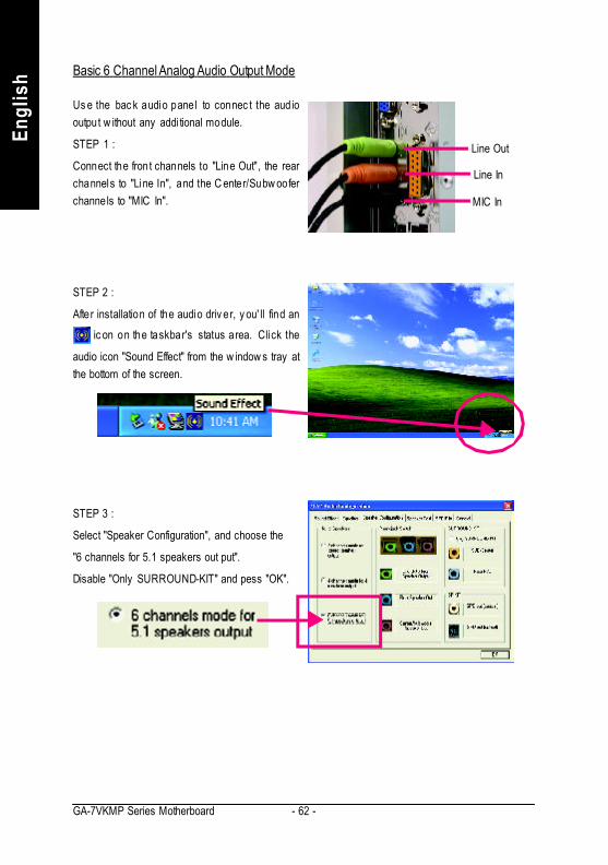
Us e the bac k audio panel to connec t the audiooutput w ithout any addi tional module.
STEP 1 :
Connect the front channels to "Line Out", the rearchannels to "Line In", and the C enter/Subw ooferchannels to "MIC In".
Basic 6 Channel Analog Audio Output Mode
Line Out
Line In
MIC In
STEP 2 :
After installation of the audio driv er, y ou' ll find an
ic on on the taskbar's status area. Click the
audio icon "Sound Effect" from the w indow s tray atthe bottom of the screen.
STEP 3 :
Select "Speaker Configuration", and choose the
"6 channels for 5.1 speakers out put".
Disable "Only SURROUND-KIT" and pess "OK".

Technical Reference- 63 -
English
STEP 1 :
Insert the "Audio Combo Kit" in the back of the case,and fix it w ith the screw .
Advanced 6 Channel Analog Audio Output Mode (using Audio Combo Kit, Optional Device)
(Audio Combo Kit prov ides SPDIF output port : optical & coax is and SURROUND-KIT : Rear R /L &
CEN /Subw oofer)
SU RROUN D-KIT ac ces s analog output to rearchannels and Center/Subw oofer channels. It is thebest solution if y ou need 6 channel output, Line Inand MIC at the same time. "SU RROUND-KIT" isincluded in the GIGABYTE unique "Audio C omboKit" as picture.
STEP 2 :
Connect the "SURR OUND-KIT" to SUR_CEN onthe M/B.

- 64 -GA-7VKMP Series Motherboard
Engl
ish
STEP 4 :
Clic k the audio icon "Sound Effect" from the w in-dow s tray at the bottom of the screen.
STEP 3 :
Connect the front channels to back audio panel's
"Line Out", the rear channels to SURROUND-KIT'sREAR R/L, and the Center/Subw oofer channels toSURROUND-KIT's SUB CENTER.
STEP 5 :
Select "Speaker Configuration", and choos e the "6channels for 5.1 speakers out put".
Enable "Only SURROUND-KIT" and press "OK".
When the "Env ironment settings" is "None", the soundw ould be per formed as stereo mode (2 channelsoutput). Please select the other settings for 6 chan-nels output.
Basic & Advanced 6 Channel Analog Audio Output Mode Notes

Technical Reference- 65 -
English
SPDIF Output Device (Optional Device)
3. Connect co-ax ia l or optical output to the AC3decoder.
1. Connect the SPDIF output dev ic e to the rear bracket of PC, and fix it w ith s crew .
2. Connect SPDIF w ire to the motherboard.
A "S/PDIF output" dev ice is available on themotherboard. Cable with rear bracket is prov idedand could link to the "S/PDIF output" connector (Aspic ture.) For the further l inkage to decoder, rearbracket prov ides coaxial cable and Fiber connect-ing port.

- 66 -GA-7VKMP Series Motherboard
Engl
ish

Appendix
English
- 67 -
Revision HistoryChapter 5 AppendixPictures below are shown in Windows XP (VUCD driver version 2.1)Appendix A: VIA KM266 / 8235 Chipset Driver Installation
A. VIA 4 in 1 Service Pack Driver:Insert the driver CD-title that came with your motherboard into your CD-ROM driver, the driverCD-title will auto start and show the installation guide. If not, please double click the CD-ROMdevice icon in "My computer", and execute the 'setup.exe'.
1. Click "VIA 4in1 ServicePack Driver" item.
(1)(2)
(3) (4)
(5) (6)
2. Click "Next". 3. Click "Yes".
4. Click "Next". 5. Click "Next".

- 68 -GA-7VKMP Series Motherboard
Engl
ish
(7) (8)
6. Click "Next". 7. Click "Next".
(9)
(10)
8. Click "Finish" to restart computer.
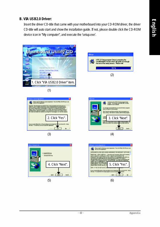
Appendix
English
- 69 -
B. VIA USB2.0 Driver:Insert the driver CD-title that came with your motherboard into your CD-ROM driver, the driverCD-title will auto start and show the installation guide. If not, please double click the CD-ROMdevice icon in "My computer", and execute the 'setup.exe'.
(1)
(2)
(3) (4)
(5) (6)
2. Click "Yes". 3. Click "Next".
4. Click "Next". 5. Click "Yes".
1. Click "VIA USB2.0 Driver" item.

- 70 -GA-7VKMP Series Motherboard
Engl
ish
(7)
(8)
(9)
(10)
7. Click "Print to File"icon.
(11)
9. Click "Finish" to restart computer.
6. Click "OK".
8. Click "OK".

Appendix
English
- 71 -
C. USB Patch Driver:Insert the driver CD-title that came with your motherboard into your CD-ROM driver, the driverCD-title will auto start and show the installation guide. If not, please double click the CD-ROMdevice icon in "My computer", and execute the 'setup.exe'.
(1)
(2)
(3)
1. Click "USB Patch Driver" item.
2. Click "Finish" to restart computer.

- 72 -GA-7VKMP Series Motherboard
Engl
ish D. KM266 VGA Driver:
Insert the driver CD-title that came with your motherboard into your CD-ROM driver, the driverCD-title will auto start and show the installation guide. If not, please double click the CD-ROMdevice icon in "My computer", and execute the 'setup.exe'.
(1)
(2)
(3) (4)
(5)
3. Click "Next".
1. Click "KM266 VGA Driver" item.
2. Click "Next".
(6)
4. Click "Finish" to restart computer.

Appendix
English
- 73 -
(1)
Revision HistoryAppendix B: RealTek AC'97 Audio DriverInsert the driver CD-title that came with your motherboard into your CD-ROM driver, the driver CD-title will auto start and show the installation guide. If not, please double click the CD-ROM device iconin "My computer", and execute the setup.exe.
Press "Audio" icon.
1. Click "Realtek AC'97 Audio Driver" item.
(2)
(3) (4)
(5)
3. Click "Next".2. Click "Next".
4. Click "Finish" to restart computer.

- 74 -GA-7VKMP Series Motherboard
Engl
ish Revision HistoryAppendix C: RealTek 8139/8100 LAN Driver
Insert the driver CD-title that came with your motherboard into your CD-ROM driver, the driver CD-title will auto start and show the installation guide. If not, please double click the CD-ROM device iconin "My computer", and execute the setup.exe.
(1)
(2)
(3) (4)
(5)
2. Click "Next".
1. Click "RealTek 8139/8100 LAN Driver" item.
Press "Network" icon.
3. Click "Finish" to restart computer.
(6)

Appendix
English
- 75 -
Appendix D: EasyTune 4 Utilities InstallationInsert the driver CD-title that came with your motherboard into your CD-ROM driver, the driver CD-title will auto start and show the installation guide. If not, please double click the CD-ROM device iconin "My computer", and execute the setup.exe.
(1) (2)
(3)
(4)
(5)
2. Click "Next".
(6)
1. Click "Gigabyte Utilities".
Press "Tools" icon.
3. Click "Next".
4. Click "Finish" to restart computer.
2. Click "EasyTune 4 (Trial Version)".

- 76 -GA-7VKMP Series Motherboard
Engl
ish Appendix E: BIOS Flash Procedure
BIOS update procedure:Method 1:We use GA-7VTX motherboard and Flash841 BIOS flash utility as example.Please flash the BIOS according to the following procedures if you are now under the DOS mode.
Flash BIOS Procedure:STEP 1:(1) Please make sure your system has installed the extraction utility such as winzip or pkunzip.
Firstly you have to install the extraction utility such as winzip or pkunzip for unzip the files. Both ofthese utilities are available on many shareware download pages like http://www.shareware.cnet.com
STEP 2:Make a DOS boot diskette. (See example: Windows 98 O.S.)Beware: Windows ME/2000 are not allowed to make a DOS boot diskette.(1) With an available floppy disk in the floppy drive. Please leave the diskette "UN-write protected"
type. Double click the "My Computer" icon from Desktop, then click "3.5 diskette (A)" and rightclick to select "Format (M)".

Appendix
English
- 77 -
(2) Select the "Quick (erase)" for Format Type, and pick both "Display summary when finished" and"Copy system files", after that press "Start". That will format the floppy and transfer the neededsystem files to it.Beware: This procedure will erase all the prior data on that floppy, so please proceed accordingly.
(3) After the floppy has been formatted completely, please press "Close".

- 78 -GA-7VKMP Series Motherboard
Engl
ish
Methods and steps: I. Update BIOS through Internet
a. Click "Internet Update" iconb. Click "Update New BIOS" iconc. Select @BIOS™ severd. Select the exact model name on your motherboarde. System will automatically download and update the BIOS.
(3)
Click " ". Click here.
Method 2:If your OS is Win9X, we recommend that you used Gigabyte @BIOS™ Program to flash BIOS.
(1) (2)
1. Click "Gigabyte Utilities".
Press "Tools" icon.
2. Click "@BIOS Writer Ver.1.08q".
Appendix
English
- 79 -
II. Update BIOS NOT through Internet:a. Do not click "Internet Update" iconb. Click "Update New BIOS"c. Please select "All Files" in dialog box while opening the old file.d. Please search for BIOS unzip file, downloading from internet or any other methods (such as:
7VKMP.F1h).e. Complete update process following the instruction.
III. Save BIOSIn the very beginning, there is "Save Current BIOS" icon shown in dialog box. It means to savethe current BIOS version.
IV. Check out supported motherboard and Flash ROM:In the very beginning, there is "About this program" icon shown in dialog box. It can help youcheck out which kind of motherboard and which brand of Flash ROM are supported.
Note:a. In method I, if it shows two or more motherboard's model names to be selected, please make
sure your motherboard's model name again. Selecting wrong model name will cause thesystem unbooted.
b. In method II, be sure that motherboard's model name in BIOS unzip file are the same as yourmotherboard's. Otherwise, your system won't boot.
c. In method I, if the BIOS file you need cannot be found in @BIOS™ server, please go ontoGigabyte's web site for downloading and updating it according to method II.
d. Please note that any interruption during updating will cause system unbooted

- 80 -GA-7VKMP Series Motherboard
Engl
ish STEP 3: Download BIOS and BIOS utility program.
(1) Please go to Gigabyte website http://www.gigabyte.com.tw/index.html, and click "Support".
(2) From Support zone, click the "Motherboards BIOS & Drivers".

Appendix
English
- 81 -
(3) We use GA-7VTX motherboard as example. Please select GA-7VTX by Model or Chipsetoptional menu to obtain BIOS flash files.
(4) Select an appropriate BIOS version (For example: F4), and click to download the file. It will popup a file download screen, then select the "Open this file from its current location" and press "OK".

- 82 -GA-7VKMP Series Motherboard
Engl
ish (5) At this time the screen shows the following picture, please click "Extract" button to unzip the files.
(6) Please extract the download files into the clean bootable floppy disk A mentioned in STEP 2, andpress "Extract".

Appendix
English
- 83 -
STEP 4: Make sure the system will boot from the floppy disk.(1) Insert the floppy disk (contains bootable program and unzip file) into the floppy drive A. Then,
restart the system. The system will boot from the floppy disk. Please press <DEL> key to enterBIOS setup main menu when system is boot up.
(2) Once you enter the BIOS setup utility, the main menu will appear on the screen. Use the arrowsto highlight the item "BIOS FEATURES SETUP".
7VTX F1Check System Health OKAMD-Athlon(tm)Processor-900MHzChecking NVRAM...262144KB
Wait...Press F1 to enter Dual BIOS Utility. Press ESC to quitPress any key to contiune
( C ) American Megatrends Inc.,63-0001-001199-00101111-071595-VIA_K7-GA7VTX1-F
American Release:09/16/99Megatrends AMIBIOS (C) 1999 American Megatrend
AMIBIOS SIMPLE SETUP UTILITY - VERSION 1.24b
(C) 1999 American Megatrends, Inc. All Rights Reserved
STANDARD CMOS SETUP INTEGRATED PERIPHERALS
BIOS FEATURES SETUP HARDWARE MONITOR & MISC SETUP
CHIPSET FEATURES SETUP SUPERVISOR PASSWORD
POWER MANAGEMENT SETUP USER PASSWORD
PNP / PCI CONFIGURATION IDE HDD AUTO DETECTION
LOAD BIOS DEFAULTS SAVE & EXIT SETUP
LOAD SETUP DEFAULTS EXIT WITHOUT SAVING
ESC: Quit : Select Item (Shift)F2 : Change Color F5: Old Values
F6: Load BIOS Defaults F7: Load Setup Defaults F10:Save & Exit
Time, Date , Hard Disk Type…

- 84 -GA-7VKMP Series Motherboard
Engl
ish (3) Press "Enter" to enter "BIOS FEATURES SETUP" menu. Use the arrows to highlight the item
"1st Boot Device", and then use the "Page Up" or "Page Down" keys to select "Floppy".
(4) Press "ESC" to go back to previous screen. Use the arrows to highlight the item "SAVE & EXITSETUP" then press "Enter". System will ask "SAVE to CMOS and EXIT (Y/N)?" Press "Y"and "Enter" keys to confirm. Now the system will reboot automatically, the new BIOS settingwill be taken effect next boot-up.
AMIBIOS SETUP - BIOS FEATURES SETUP
( C ) 2001 American Megatrends, Inc. All Rights Reserved
1st Boot Device : Floppy
2nd Boot Device : IDE-0
3rd Boot Device : CDROM
S.M.A.R.T. for Hard Disks : Disabled
BootUp Num-Lock : On ESC: Quit : Select Item
Floppy Drive Seek : Disabled F1 : Help PU/PD/+/- : Modify
Password Check : Setup F5 : Old Values (Shift)F2: Color
F6 : Load BIOS Defaults
F7 : Load Setup Defaults
AMIBIOS SIMPLE SETUP UTILITY - VERSION 1.24b
(C) 2001 American Megatrends, Inc. All Rights Reserved
STANDARD CMOS SETUP INTEGRATED PERIPHERALS
BIOS FEATURES SETUP HARDWARE MONITOR & MISC SETUP
CHIPSET FEATURES SETUP SUPERVISOR PASSWORD
POWER MANAGEMENT SETUP USER PASSWORD
PNP / PCI CONFIGURATION IDE HDD AUTO DETECTION
LOAD BIOS DEFAULTS SAVE & EXIT SETUP
LOAD SETUP DEFAULTS EXIT WITHOUT SAVING
ESC: Quit : Select Item (Shift)F2 : Change Color F5: Old Values
F6: Load BIOS Defaults F7: Load Setup Defaults F10:Save & Exit
Save Data to CMOS & Exit SETUP
Save to CMOS and EXIT (Y/N)? Y
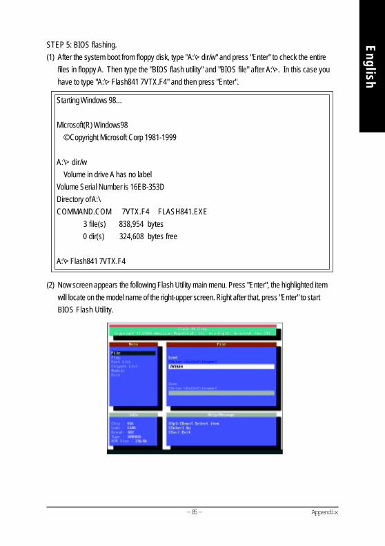
Appendix
English
- 85 -
STEP 5: BIOS flashing.(1) After the system boot from floppy disk, type "A:\> dir/w" and press "Enter" to check the entire
files in floppy A. Then type the "BIOS flash utility" and "BIOS file" after A:\>. In this case youhave to type "A:\> Flash841 7VTX.F4" and then press "Enter".
(2) Now screen appears the following Flash Utility main menu. Press "Enter", the highlighted itemwill locate on the model name of the right-upper screen. Right after that, press "Enter" to startBIOS Flash Utility.
Starting Windows 98…
Microsoft(R) Windows98 © Copyright Microsoft Corp 1981-1999
A:\> dir/w Volume in drive A has no labelVolume Serial Number is 16EB-353DDirectory of A:\COMMAND.COM 7VTX.F4 FLASH841.EXE 3 file(s) 838,954 bytes 0 dir(s) 324,608 bytes free
A:\> Flash841 7VTX.F4
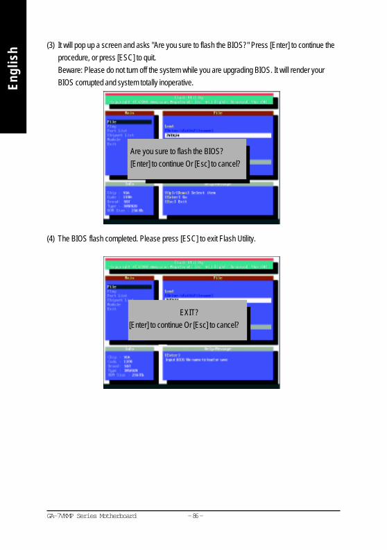
- 86 -GA-7VKMP Series Motherboard
Engl
ish (3) It will pop up a screen and asks "Are you sure to flash the BIOS?" Press [Enter] to continue the
procedure, or press [ESC] to quit.Beware: Please do not turn off the system while you are upgrading BIOS. It will render yourBIOS corrupted and system totally inoperative.
(4) The BIOS flash completed. Please press [ESC] to exit Flash Utility.
Are you sure to flash the BIOS?[Enter] to continue Or [Esc] to cancel?
EXIT?[Enter] to continue Or [Esc] to cancel?

Appendix
English
- 87 -
STEP 6: Load BIOS defaults.Normally the system redetects all devices after BIOS has been upgraded. Therefore, we highlyrecommend reloading the BIOS defaults after BIOS has been upgraded. This important stepresets everything after the flash.
(1) Take out the floppy diskette from floppy drive, and then restart the system. The boot up screen willindicate your motherboard model and current BIOS version.
(2) Don't forget to press <DEL> key to enter BIOS setup again when system is boot up. Use thearrows to highlight the item "LOAD SETUP DEFAULTS" then press "Enter". System will ask"Load Setup Defaults (Y/N)?" Press "Y" and "Enter" keys to confirm.
7VTX F4Check System Health OKAMD-Athlon(tm)Processor-900MHzChecking NVRAM...262144KB
Wait...Press F1 to enter Dual BIOS Utility. Press ESC to quitPress any key to contiune
( C ) American Megatrends Inc.,63-0001-001199-00101111-071595-VIA_K7-GA7VTX1-F
American Release:09/16/99Megatrends AMIBIOS (C) 1999 American Megatrend
AMIBIOS SIMPLE SETUP UTILITY - VERSION 1.24b
(C) 2001 American Megatrends, Inc. All Rights Reserved
STANDARD CMOS SETUP INTEGRATED PERIPHERALS
BIOS FEATURES SETUP HARDWARE MONITOR & MISC SETUP
CHIPSET FEATURES SETUP SUPERVISOR PASSWORD
POWER MANAGEMENT SETUP USER PASSWORD
PNP / PCI CONFIGURATION IDE HDD AUTO DETECTION
LOAD BIOS DEFAULTS SAVE & EXIT SETUP
LOAD SETUP DEFAULTS EXIT WITHOUT SAVING
ESC: Quit : Select Item (Shift)F2 : Change Color F5: Old Values
F6: Load BIOS Defaults F7: Load Setup Defaults F10:Save & Exit
Load Setup Defaults
Load Setup Defaults? (Y/N)?N

- 88 -GA-7VKMP Series Motherboard
Engl
ish (3) Use the arrows to highlight the item "SAVE & EXIT SETUP" and press "Enter". System will
ask "SAVE to CMOS and EXIT (Y/N)?" Press "Y" and "Enter" keys to confirm. Now thesystem will reboot automatically, the new BIOS setting will be taken effect next boot-up.
(4) Congratulate you have accomplished the BIOS flash procedure.
AMIBIOS SIMPLE SETUP UTILITY - VERSION 1.24b
(C) 2001 American Megatrends, Inc. All Rights Reserved
STANDARD CMOS SETUP INTEGRATED PERIPHERALS
BIOS FEATURES SETUP HARDWARE MONITOR & MISC SETUP
CHIPSET FEATURES SETUP SUPERVISOR PASSWORD
POWER MANAGEMENT SETUP USER PASSWORD
PNP / PCI CONFIGURATION IDE HDD AUTO DETECTION
LOAD BIOS DEFAULTS SAVE & EXIT SETUP
LOAD SETUP DEFAULTS EXIT WITHOUT SAVING
ESC: Quit : Select Item (Shift)F2 : Change Color F5: Old Values
F6: Load BIOS Defaults F7: Load Setup Defaults F10:Save & Exit
Save Data to CMOS & Exit SETUP
Save to CMOS and EXIT (Y/N)? Y

Appendix
English
- 89 -
Appendix F: AcronymsAcronyms MeaningACPI Advanced Configuration and Power InterfaceAPM Advanced Power ManagementAGP Accelerated Graphics PortAMR Audio Modem RiserACR Advanced Communications RiserBIOS Basic Input / Output SystemCPU Central Processing UnitCMOS Complementary Metal Oxide SemiconductorCRIMM Continuity RIMMCNR Communication and Networking RiserDMA Direct Memory AccessDMI Desktop Management InterfaceDIMM Dual Inline Memory ModuleDRM Dual Retention MechanismDRAM Dynamic Random Access MemoryDDR Double Data RateECP Extended Capabilities PortESCD Extended System Configuration DataECC Error Checking and CorrectingEMC Electromagnetic CompatibilityEPP Enhanced Parallel PortESD Electrostatic DischargeFDD Floppy Disk DeviceFSB Front Side BusHDD Hard Disk DeviceIDE Integrated Dual Channel EnhancedIRQ Interrupt RequestI/O Input / OutputIOAPIC Input Output Advanced Programmable Input ControllerISA Industry Standard ArchitectureLAN Local Area Network
to be continued......
- 90 -GA-7VKMP Series Motherboard
Engl
ish Acronyms Meaning
LBA Logical Block AddressingLED Light Emitting DiodeMHz MegahertzMIDI Musical Instrument Digital InterfaceMTH Memory Translator HubMPT Memory Protocol TranslatorNIC Network Interface CardOS Operating SystemOEM Original Equipment ManufacturerPAC PCI A.G.P. ControllerPOST Power-On Self TestPCI Peripheral Component InterconnectRIMM Rambus in-line Memory ModuleSCI Special Circumstance InstructionsSECC Single Edge Contact CartridgeSRAM Static Random Access MemorySMP Symmetric Multi-ProcessingSMI System Management InterruptUSB Universal Serial BusVID Voltage ID

Appendix
English
- 91 -
Technical Support/RMA SheetCustomer/Country: Company: Phone No.:Contact Person: E-mail Add. :
Model name/Lot Number: PCB revision:BIOS version: O.S./A.S.:
Hardware Mfs. Model name Size: Driver/Utility:ConfigurationCPUMemoryBrandVideo CardAudio CardHDDCD-ROM /DVD-ROMModemNetworkAMR / CNRKeyboardMousePower supplyOther Device
Problem Description:

- 92 -GA-7VKMP Series Motherboard
Engl
ish