morphological evolution of block copolymer nanocomposites
TRANSCRIPT

Morphological evolution of block copolymer nanocomposites submittedto extensional flows
Leice G. Amurin
Mechanical Engineering Department, �Ecole de Technologie Sup�erieure (ETS), Montreal, Qu�ebec H3C 1 K3,Canada and Metallurgical and Materials Engineering Department, Escola Polit�ecnica, University of S~ao Paulo,
S~ao Paulo, Brazil
Danilo J. Carastan
Center for Engineering, Modeling and Applied Social Sciences, Federal University of ABC (UFABC), Santo Andr�e,S~ao Paulo, Brazil
Nicole R. Demarquettea)
Mechanical Engineering Department, �Ecole de Technologie Sup�erieure (ETS), Montreal, Qu�ebec H3C 1 K3, Canada
(Received 1 July 2015; final revision received 22 November 2015; published 30 December 2015)
Abstract
In this work, the effect of extensional flow on the morphology of polystyrene-b-poly(ethylene-co-butylene)-b-polystyrene (SEBS) triblock
copolymers and their clay-containing nanocomposites was evaluated. Four types of SEBS copolymers with different block compositions and
cylindrical morphology were chosen to understand the effects of cylinder orientation and state of clay dispersion on the evolution of mor-
phology during extensional flow. The effect of clay concentration (ranging from 2.5 to 7.5 wt. %) was also studied. The samples were sub-
jected to extensional flow using a Sentmanat extensional rheometer attached to a rotational rheometer at Hencky strain rates varying from
0.01 to 20 s�1. Small angle X-ray scattering analysis was subsequently performed to evaluate the morphological changes caused by exten-
sional flow. When preoriented block copolymers [SEBS-30% PS (polystyrene)] and their nanocomposites undergo elongation, the styrene
cylinders and clay nanoparticles align themselves in the flow direction and their rheological behavior and morphological evolution are influ-
enced by the stretching direction (longitudinal and transverse), strain rate magnitude, clay concentration, and dispersion state of the clay
nanoparticles. When isotropic block copolymers (SEBS-13% PS) undergo elongation, it was observed that the PS cylinders only exhibit
structural alignment in the stretching direction in the presence of clay. Block copolymer molecules can exhibit different relaxation times
depending upon the volume fraction of PS domains (13% or 30%). The addition of clay, however, hinders complete relaxation, helping to
promote a permanent domain alignment after flow cessation, especially in hard-to-align copolymers. VC 2016 The Society of Rheology.[http://dx.doi.org/10.1122/1.4938278]
I. INTRODUCTION
Block copolymers are materials that can be used in sev-
eral applications due to their molecular characteristics.
Their molecules are composed of blocks usually immisci-
ble with each other, resulting in phase-separated structures
at the nanometer level. According to the thermodynamic
affinity between the blocks of a copolymer, as well as their
absolute and relative length, block copolymers can present
different types of morphologies, the most common ones
being the spherical, lamellar, and cylindrical structures
[1–6]. In particular, styrenic block copolymers such as
polystyrene-b-polyisoprene-b-polystyrene (SIS) and poly-
styrene-b-poly(ethylene-co-butylene)–b-polystyrene triblock
copolymers (SEBS) have drawn the attention of the industry,
as they can be used as thermoplastic elastomers (TPE) due
to their structure composed of immiscible rigid (styrene) and
flexible blocks (such as ethylene-co-butylene (EB), butadi-
ene, or isoprene) [7–9].
More recently, these materials have gained attention for a
different reason, as they can present piezoelectric properties
[10–12], and thus can be used as sensors, actuators for artifi-
cial muscles, and other applications [13–16]. Whether block
copolymers are used for their mechanical or electrical prop-
erties, there is a need to control their morphology [17]. In the
case of a block copolymer with a certain chemical structure
and molecular weight, this control can be achieved during
processing and through the addition of well-tailored nanopar-
ticles [18–22]. In particular, the morphology of block
copolymers can be controlled by subjecting them to shear or
extensional flows. Moreover, the addition of nanoparticles
can induce morphological changes on a block copolymer,
depending on the chemical affinity between the nanoparticles
and the different domains present in the copolymer [23–26].
Few studies have been published regarding the morpho-
logical evolution of block copolymer nanocomposites above
a)Author to whom correspondence should be addressed; electronic mail:
VC 2016 by The Society of Rheology, Inc.J. Rheol. 60(1), 175-189 January/February (2016) 0148-6055/2016/60(1)/175/15/$30.00 175

the glass transition temperature of the hard domains, espe-
cially when the block copolymers are subject to extensional
flows at high Hencky strain rates. Burghardt et al. [27,28]
studied the morphological evolution of SEBS block copoly-
mers containing 13 wt. % PS blocks, using a uniaxial elonga-
tion device attached to a small angle X-ray scattering
(SAXS) line. They revealed details about structural changes
of the polymeric chains such as the structural deformation
and rotation of the PS domains in the stretching direction. As
the structural relaxation time was very small, the PS domain
alignment was not maintained after extensional flow
cessation.
Aiming at future applications, tailoring the morphology
of these copolymers by avoiding such relaxation processes is
important to keep the structural alignment after flow cessa-
tion. One strategy is to evaluate how the presence of nano-
particles affects the final morphology. Very few works have
been published focusing on the rheological behavior and
morphological changes in block copolymer nanocomposites
under extensional flow. In a previous work, we evaluated the
effects of extensional flow on the morphology of SEBS
copolymers containing 30 wt. % PS domains, which pre-
sented a cylindrical structure, and on the morphology of their
nanocomposites containing 5 wt. % clay [29]. Both the cylin-
ders and the clay particles were initially aligned by extru-
sion, and the samples were tested in uniaxial extensional
flow in directions parallel and perpendicular to the axis of
the PS cylinders [29]. When the materials were tested in the
direction of extrusion (direction of flow parallel to the axis
of the cylinders), the copolymers and nanocomposites
behaved according to Trouton’s rule and the clay particles
did not seem to affect the rheological behavior of the block
copolymers. When the materials were tested in a direction
perpendicular to the cylinders, the materials exhibited strain
softening followed by strain hardening. In that case, the
presence of clay affected the rheological behavior of the
copolymers. SAXS experiments revealed that the cylindri-
cal domains and clay nanoparticles tend to align in the
drawing direction regardless of previous cylinder and clay
orientation. The magnitude and speed of alignment of the
cylinders and clay particles were shown to depend on the
Hencky strain rate and state of clay dispersion: exfoliated
clay nanoparticles forming a network probably hindered
cylinder alignment, while intercalated clay nanoparticles
within the cylinders probably caused the opposite effect,
enhancing the alignment of the cylindrical domains. The
orientation of the nanostructure was shown to be affected
by a competition between the relaxation of the block
copolymer molecules and hydrodynamic effects promoted
by the clay nanoparticles.
In order to complement the observations obtained by
Carastan et al. [29], other samples with different clay con-
centrations and nonoriented (isotropic) domains were
obtained and tested in the present work. Four types of block
copolymers were used, all presenting a morphology of cylin-
drical styrene blocks within an EB matrix, but containing
different fractions of polystyrene blocks (13 and 30 wt. %).
While the copolymers containing 30 wt. % PS were aligned
during extrusion, those containing 13 wt. % presented an iso-
tropic morphology after processing. The effect of clay con-
centration (varying from 2.5 to 7.5 wt. %) on the
morphological evolution of the samples containing 30 wt. %
PS was also studied. After characterization by X-ray diffrac-
tion (XRD) and SAXS to determine the nanocomposites
structure and orientation induced during processing, the sam-
ples were subjected to extensional flow using a Sentmanat
extensional rheometer [30] (SER) coupled to a rotational
rheometer and their morphology was studied by SAXS after
elongation.
II. EXPERIMENTAL
A. Materials and processing
1. Materials
Four SEBS block copolymers supplied by Kraton
Polymers were used. The characteristics of the copolymers
are shown in Table I. All samples presented morphology of
PS cylinders within the EB phase, as shown further in this
work. The molecular weight was determined by gel permea-
tion chromatography (GPC) in THF (tetrahydrofuran) solution
using Viscotek HT-GPC (350A) equipment. The organoclay
used in this study was a commercial montmorillonite Cloisite
20A modified with a quaternary ammonium salt, supplied by
Southern Clay Products, Inc (Gonzales, USA).
a. Processing. The copolymers and their nanocompo-
sites were melt processed in a Haake Rheomix PTW-16
double-screw extruder attached to a Thermo Haake
PolyLab 900 torque rheometer, using a ribbon die 55-2301
having a 25 mm width and 1 mm thickness. The processing
conditions were 150 �C (SEBS-13 and SEBS-13-MA) and
220 �C (SEBS-30 and SEBS-30-MA) in the six temperature
zones of the extruder and screw speed of 100 rpm. Details
of the preparation technique were reported in a previous
related work [26].
TABLE I. Properties of the SEBS block copolymers.
Polymer Grade wt. % PS Mw (g/mol) Mn (g/mol) Mw/Mn Clay concentration (wt. %)
SEBS-30 G1652 30 73 000 68 000 1.08 2.5, 5, 7.5
SEBS-30-MAa FG1901 30 77 000 44 000 1.74 2.5, 5, 7.5
SEBS-13 G1645 13 122 000 85 000 1.43 5
SEBS-13-MAb FG1924 13 127 000 87 000 1.46 5
aContains 1%–2% maleic anhydride grafted in the PEB phase.bContains 0.7%–1.3% maleic anhydride grafted in the PEB phase.
176 AMURIN, CARASTAN, AND DEMARQUETTE

B. Characterization
1. Structural and morphological characterization of
the block copolymers and nanocomposites
a. Small-angle X-ray scattering. The morphology of the
block copolymers and nanocomposites before and after
extensional deformation was evaluated by SAXS. The tests
were carried out using the synchrotron source of the
National Synchrotron Light Laboratory (LNLS), Campinas,
Brazil, with an X-ray wavelength of 1.488 A and a sample-
to-detector distance of 950 mm and also using a Bruker
NanoSTAR equipped with 1.5 kV CuKa radiation and a
sample-to-detector distance of 650 mm. The data were proc-
essed using the software Fit2D. Bidimensional detectors
were used in order to evaluate anisotropic features of the
samples. Corresponding 1D SAXS curves were plotted as a
function of the scattering vector q from the integration of 2D
patterns over a sector covering an azimuthal angle range
between 60� and 90�, depending on the sample.
b. X-ray diffraction. The clay interlayer distance was
evaluated by XRD, using an X’Pert PRO Diffractometer de-
tector X’Celerator, with a 40 kV, 40 mA CuKa source. The
x-ray beam scanned angles ranging from 1.15� to 10� at a
0.05� step. The samples (clay and nanocomposites) were an-
alyzed in powder form, which was obtained after grinding
the samples previously frozen in liquid nitrogen.
c. Transmission electron microscopy. Transmission elec-
tron microscopy (TEM) was performed with a Carl Zeiss
CEM 902 transmission electron microscope for the SEBS-
30. The samples were cut into ultrathin slices (40–60 nm
thick) using an ultramicrotome at �100 �C. The slices were
stained for 30 min with RuO4 vapor in order to reveal the
block copolymer morphology, as RuO4 stains preferentially
the PS domains preferentially.
2. Rheological measurements
Different techniques can be used to study the rheological
behavior under extensional flow [31–34]. In the present work,
the samples were subjected to extensional flow using an SER
geometry [35] coupled to an ARES rheometer controlled
strain rheometer from TA instruments. The SER geometry
consists of two rolls rotating in opposite directions.
Rectangular samples are fixed to each roll and due to the
stretching created by the roll motion at the same angular ve-
locity, a tangential force is generated and consequently a uni-
form extensional deformation is applied along the specimens.
The extensional viscosity (gEþ) can then be calculated by
knowing the resistance to the deformation. Rectangular sam-
ples with dimensions of (20� 6� 1) mm were cut from the
extruded strips in directions parallel [longitudinal direction
(L)] and perpendicular [transverse direction (T)] to the extru-
sion direction. Figure 1 presents the directions and dimen-
sions of the extruded ribbon samples. Rheological tests in
extensional flow, for the samples containing 13 and 30 wt. %
PS, were carried out at 120 and 200 �C, respectively. The tem-
peratures were chosen in order to maintain the morphological
structure after extrusion. Four strain rates were applied to the
samples: 0.01, 0.1, 1, and 20 s�1. Steady shear tests were also
carried out on some samples using a 25 mm rotational geome-
try. These samples were prepared by compression molding at
200 �C, being molded into 25� 1 mm disks.
After the rheological tests, just after the failure, the sam-
ples were cooled down to room temperature using a com-
pressed air jet. The cooled samples were then analyzed at
different spots along the deformed samples following the
procedures reported in Carastan et al. [26]. The position of
the different spots corresponded to different Hencky strains,
as can be seen in Fig. 2.
The Hencky strain (e) of each spot analyzed (ui) was cal-
culated by the following Eq. (1)
e ¼ lnDui0 þ 6:36ð Þ
6:36
� �; (1)
where Dui0 represents the difference between the analyzed
deformation point (ui) and zero deformation (u0). The value
6.36 mm is half of the distance between the axis of the SER
geometry rolls.
FIG. 1. Scheme shows how the specimens were cut for the extensional tests
from tape samples obtained by melt extrusion: x is the direction parallel to
the extrusion flow, y is the direction perpendicular to the extrusion flow, and
z is perpendicular to the tape plane.
FIG. 2. Scheme of the specimens analyzed by SAXS after the extensional
test.
177BLOCK COPOLYMER NANOCOMPOSITES IN EXTENSIONAL

3. Dynamic mechanical analysis
Dynamic mechanical analysis (DMA) was done using a
Q800 DMA from TA Instruments in tensile mode. Rectangular
samples of 20� 6.5� 1 mm were cut from the extruded strips in
directions parallel [longitudinal direction (L)] and perpendicular
[transverse direction (T)] to the extrusion direction, as shown in
Fig. 1. The samples were tested in oscillating mode, being heated
from �100 to 140 �C at a 5 �C/min rate. The oscillation fre-
quency was set at 1 Hz and the amplitude was 0.2lm. The ten-
sile storage modulus (E0) and loss modulus (E00) were evaluated.
III. RESULTS AND DISCUSSION
A. Morphology characterization
The morphological characterization of the samples will
be discussed in two parts. First, the state of clay dispersion
assessed by XRD will be presented. Then, the results of the
SAXS analysis of the block copolymers prior to rheological
tests and the influence of the addition of clay on the copoly-
mer structure will be reported.
1. Clay nanostructure
Table II reports the diffraction angle (2h) related to the
(001) plane of the clay, the basal spacing [d(001)] and the ba-
sal spacing variation after clay being added to the non-
maleated copolymers [Dd(001)]. It can be seen that for all the
composites the interlayer distance between the clay platelets
increased about 1 nm, indicating that polymeric chains were
intercalated between clay multilayers. It can also be seen
that the interlayer distance between the clay platelets
decreases as a function of clay concentration (SEBS-
30þ20A). This result can be in parts due to the effect of a
partial exfoliation, which is common to this type of SEBS
nanocomposite [36]. Especially at lower clay concentrations
the clay tactoids are very small, and the combination of par-
tial exfoliation and disordered intercalation can shift the dif-
fraction peaks to lower Bragg angles [37].
The results corroborate the works previously reported
[25,26] who studied the state of clay dispersion in triblock
copolymers. Clay particle surfaces were shown to have
higher interaction with the PS chains, which exhibit a mild
polarity, necessary to promote the intercalation into the clay
galleries, which are also slightly polar, despite the presence
of the double-tailed apolar ammonium cations [38].
The XDR patterns (not shown) for maleated SEBS nano-
composites did not exhibit any diffraction peak, indicating
the probable formation of exfoliated structures. Exfoliation
may have occurred due to the better affinity between the
maleated groups and the clay, as discussed in previous stud-
ies [26].
2. Morphological structure of block copolymers
Figure 3 shows 1D SAXS plots obtained with the X-ray
beam parallel to the z direction (perpendicular to the tape
plane, as shown in Fig. 1). Samples were tested in three dif-
ferent clay concentrations, but 1D SAXS curves are shown
only for samples containing 5 wt. % clay, because in this
study clay concentration does not interfere in the morpholog-
ical structure of the block copolymers. It can be seen that in
1D SAXS plots no changes were observed in the features of
the patterns upon clay addition. Bragg peak maxima appear
at angles for which the ratios qn/q1 are equal to 1, �3, �7, and
�9, indicating that the pure copolymers and their nanocom-
posites present similar cylindrical hexagonal structures. It
can be also seen from Fig. 3(b) that the peak sequences for
SEBS-13 and SEBS-13-MA are less defined than the ones
TABLE II. Diffraction angle of the basal plane (2h), clay interlayer spacing
[d(001)] and variation of the clay spacing in the nanocomposites [Dd(001)].
Samples 2h (deg) d(001) (nm) Dd(001) (nm)
SEBS-30þ20A (2.5 wt. %) 2.37 3.73 1.27
SEBS-30þ20A (5 wt. %) 2.49 3.55 1.09
SEBS-30þ20A (7.5 wt. %) 2.55 3.47 1.01
SEBS-13þ20A (5 wt. %) 2.54 3.47 1.01
Clay (Cloisite 20A) 3.58 2.46 —
FIG. 3. 1D SAXS plots [intensity I(q) vs scattering vector, q obtained by
SAXS patterns for pure copolymers and nanocomposites]. (a) SEBS-30
and SEBS-30-MA and its nanocomposites (5 wt. % clay concentration) and
(b) SEBS-13/0, SEBS-13/0-MA and their nanocomposites (5 wt. % clay
concentration).
178 AMURIN, CARASTAN, AND DEMARQUETTE

for SEBS-30 copolymers. This could be an indication of a
poorer long-range order of the PS cylinders, once PS blocks
are shorter for SEBS-13 copolymers.
A small peak at a value of q of roughly 1.8 nm�1 can be
observed for the SEBS-30þ20 A (5 wt. %) nanocomposite.
This peak corresponds to the diffraction of the clay platelets,
which are intercalated in this sample. Such a peak cannot be
observed in the case of SEBS-13þ20A, most likely due to
the fact that the clay platelets were oriented parallel to the
x-y plane, which was perpendicular to the x-ray beam during
the observation, as will be shown later.
Using the value of the first Bragg peak (q*), it was possi-
ble to calculate the distance between the (100) planes of the
cylindrical structure [d(100)]. Table III presents these values
for all the systems studied here. It can be seen that the values
of d(100) for the copolymers containing 30 wt. % PS are
around 22.5 and 23.5 nm (SEBS-30 and SEBS-30-MA),
whereas those for SEBS containing 13 wt. % are around
24 nm, being all similar values. It can also be observed that
upon clay addition the distance between the styrene cylindri-
cal domains had a small increase [Dd(100)]. This increase was
much larger for the samples that did not contain maleic an-
hydride grafted to the EB block. A possible explanation is
that clay stacks usually try to maximize their contact with PS
domains in nonmaleated samples, whereas the presence of
MA in EB blocks favors the dispersion and exfoliation of
clay particles within the EB matrix.
In order to evaluate the alignment of the cylinder domains
and clay nanoparticles, SAXS analysis of the copolymer and
composite samples after extrusion was performed in the x, y,
and z directions, according to Fig. 1.
For the pure block copolymers, two different behaviors
were observed. Figure 4 shows the 2D SAXS patterns
obtained for the copolymers containing 30 wt. % PS [Fig.
4(a)] and 13 wt. % PS [Fig. 4(b)]. In this example, only the
SAXS patterns for SEBS-30-MA and for SEBS-13 are
shown, but the results are similar for other copolymers with
the same amount of PS. In the case of the SEBS-30 copoly-
mers, the 2D SAXS patterns indicate that the PS cylinders
are aligned parallel to the extrusion flow after processing.
The 2D SAXS pattern corresponding to the x-axis direction
also reveals that the cylinders are arranged almost in a single
crystal-like structure due to the shear occurring in a die with
planar geometry. These results corroborate the ones we
obtained previously [26]. In the case of the SEBS-13 copoly-
mers, the 2D SAXS patterns are similar in all three direc-
tions, exhibiting concentric circles indicating that the PS
cylinders were not aligned during the extrusion process. This
is probably due to the lower viscosity of these copolymers,
and the smaller fraction of PS blocks.
The presence of clay adds distinctive features to the 2D
SAXS patterns of the nanocomposites. Figures 5(a) and 5(b)
present SAXS patterns for SEBS-13þ20A and SEBS-13-
MAþ20A in the x, y, and z directions. The patterns for
SEBS13þ20A reveal a set of halos/spots marked as C1 in
Fig. 5(a), which correspond to the Bragg peaks associated
with the layers of the clay stacks. The maxima of these halos
are aligned in the z direction, indicating that the clay plate-
lets are parallel to the x-y plane, which contains the extrusion
direction x. A different pattern is seen for SEBS-13-
MAþ20A, as no sharp Bragg peak from the clay nanopar-
ticles can be identified, probably because they are dispersed
individually within the matrix. However, the scattering pat-
tern indicates that even these particles lie parallel to the
plane of the tape, as their maximum scattering intensities are
parallel to the z-axis, indicating that most of the clay plate-
lets are parallel to the x-y plane, along the extrusion direc-
tion. It should be noted that the presence of clay did not
enhance the alignment of PS cylinders, and as a result they
remain isotropic despite the alignment of the clay. On the
other hand, the addition of clay to SEBS-30 and SEBS-30-
MA resulted in the formation of nanocomposites with an
aligned morphology (results not shown), where the cylinders
were oriented in the direction of extrusion, and most clay
TABLE III. Average distance between the (100) planes of the cylindrical
structure [d(100)] calculated from the SAXS results. Dd(100) is the difference
between d(100) of the nanocomposites and their respective pure copolymers.
Samples d(100) (nm) Dd(100) (nm)
SEBS-30 22.54 *a
SEBS-30-MA 23.51 *a
SEBS-13 24.03 *a
SEBS-13-MA 24.52 *a
SEBS-30þ20A (2.5%) 22.86 0.32
SEBS-30þ20A (5%) 24.72 2.18
SEBS-30þ20A (7.5%) 25.04 2.50
SEBS-30-MAþ20A (2.5%) 23.94 0.43
SEBS-30-MAþ20A (5%) 24.16 0.65
SEBS-30-MAþ20A (7.5%) 24.18 0.67
SEBS-13þ20A (5%) 25.08 1.05
SEBS-13-MAþ20A (5%) 24.75 0.23
a“*” not applicable.
FIG. 4. 2D SAXS patterns of extruded copolymer ribbons containing 13 and
30 wt. % PS in the directions x, y, and z, as defined in Fig. 1: (a) SEBS-30-
MA and (b) SEBS-13.
FIG. 5. 2D SAXS patterns of extruded SEBS 13 wt. % PS nanocomposite
ribbons in the directions x, y, and z, as defined in Fig. 1: (a) SEBS-13þ20A
and (b) SEBS-13-MAþ20A. C1: halos/spots corresponding to the Bragg
peaks associated to clay stacks and C2: x-ray scattering promoted by exfoli-
ated clay nanoparticles.
179BLOCK COPOLYMER NANOCOMPOSITES IN EXTENSIONAL
nanoparticles were also aligned parallel to the x-y plane (the
plane of the ribbon). Just like in their 13 wt. % PS counter-
parts, SEBS-30 nanocomposite exhibited an intercalated struc-
ture, whereas in SEBS-30-MA the resulting morphology was
exfoliated, due to the presence of maleic anhydride. More
details in the description of the morphology of these samples
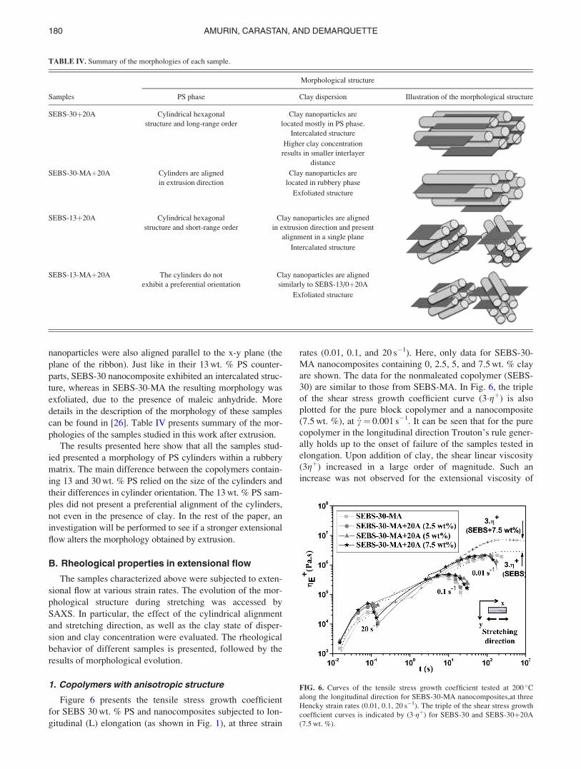
can be found in [26]. Table IV presents summary of the mor-
phologies of the samples studied in this work after extrusion.
The results presented here show that all the samples stud-
ied presented a morphology of PS cylinders within a rubbery
matrix. The main difference between the copolymers contain-
ing 13 and 30 wt. % PS relied on the size of the cylinders and
their differences in cylinder orientation. The 13 wt. % PS sam-
ples did not present a preferential alignment of the cylinders,
not even in the presence of clay. In the rest of the paper, an
investigation will be performed to see if a stronger extensional
flow alters the morphology obtained by extrusion.
B. Rheological properties in extensional flow
The samples characterized above were subjected to exten-
sional flow at various strain rates. The evolution of the mor-
phological structure during stretching was accessed by
SAXS. In particular, the effect of the cylindrical alignment
and stretching direction, as well as the clay state of disper-
sion and clay concentration were evaluated. The rheological
behavior of different samples is presented, followed by the
results of morphological evolution.
1. Copolymers with anisotropic structure
Figure 6 presents the tensile stress growth coefficient
for SEBS 30 wt. % PS and nanocomposites subjected to lon-
gitudinal (L) elongation (as shown in Fig. 1), at three strain
rates (0.01, 0.1, and 20 s�1). Here, only data for SEBS-30-
MA nanocomposites containing 0, 2.5, 5, and 7.5 wt. % clay
are shown. The data for the nonmaleated copolymer (SEBS-
30) are similar to those from SEBS-MA. In Fig. 6, the triple
of the shear stress growth coefficient curve (3�gþ) is also
plotted for the pure block copolymer and a nanocomposite
(7.5 wt. %), at _c¼ 0.001 s�1. It can be seen that for the pure
copolymer in the longitudinal direction Trouton’s rule gener-
ally holds up to the onset of failure of the samples tested in
elongation. Upon addition of clay, the shear linear viscosity
(3gþ) increased in a large order of magnitude. Such an
increase was not observed for the extensional viscosity of
TABLE IV. Summary of the morphologies of each sample.
Samples
Morphological structure
PS phase Clay dispersion Illustration of the morphological structure
SEBS-30þ20A Cylindrical hexagonal
structure and long-range order
Clay nanoparticles are
located mostly in PS phase.
Intercalated structure
Higher clay concentration
results in smaller interlayer
distance
SEBS-30-MAþ20A Cylinders are aligned
in extrusion direction
Clay nanoparticles are
located in rubbery phase
Exfoliated structure
SEBS-13þ20A Cylindrical hexagonal
structure and short-range order
Clay nanoparticles are aligned
in extrusion direction and present
alignment in a single plane
Intercalated structure
SEBS-13-MAþ20A The cylinders do not
exhibit a preferential orientation
Clay nanoparticles are aligned
similarly to SEBS-13/0þ20A
Exfoliated structure
FIG. 6. Curves of the tensile stress growth coefficient tested at 200 �Calong the longitudinal direction for SEBS-30-MA nanocomposites,at three
Hencky strain rates (0.01, 0.1, 20 s�1). The triple of the shear stress growth
coefficient curves is indicated by (3�gþ) for SEBS-30 and SEBS-30þ20A
(7.5 wt. %).
180 AMURIN, CARASTAN, AND DEMARQUETTE

the nanocomposites tested in the L direction. This can be
explained by the preferential orientation of the clay and PS
cylinders in the L direction. As the samples are stretched in
the same direction of the clay, the addition of nanoparticles
does not have a significant effect. However, in the case of
shear flow, the rotational geometry makes clay particles and
PS cylinders deviate from their original alignment, so they
exhibit more interaction with each other, increasing the over-
all viscosity of the system.
Figure 7 presents the tensile stress growth coefficient
(gEþ) as a function of time for SEBS-30, SEBS-30-MA, and
their nanocomposites tested in the transverse (T) direction.
The results are shown at four Hencky strain rates (0.01, 0.1,
1, and 20 s�1) for three clay concentrations (2.5, 5, and
7.5 wt. %). The samples elongated in the transverse direction
exhibit extension thinning for all strain rates, except 20 s�1,
which is characterized by a primary drop/plateau in the gEþ
curves. Note that in the transverse direction the gEþ plots
exhibit a three step behavior as a function of time. In the
first step, the tensile stress growth coefficient increases up
to Hencky strain values between 0.1 and 0.3, which
correspond to deformation of the PEB [poly(ethylene-co-
butylene)] domains without any significant morphological
change [27]. The second step is an extensional viscosity
decrease/plateau in the strain range 0.1< e< 1, which is the
main region where occurs strain softening and the morpho-
logical changes initiate. At the final step gEþ increases again
up to around e¼ 1, which corresponds to the completion of
morphological changes and onset of sample rupture. Due to
the extension thinning effect Trouton’s rule does not hold in
the transverse direction.
It can also be seen that in the case of the nonmaleated co-
polymer (SEBS-30), the addition of clay seemed to have a
greater effect on the tensile stress growth coefficient for
Hencky strains corresponding to the extension thinning
behavior. In this direction, the effect of clay is more evident,
and it postpones the yielding related to the rotation of the
cylinders to higher values of Hencky strain values, increas-
ing the overall transient extensional viscosity. The measured
Hencky strain values for the onset of extensional thinning at
0.01 s�1 for SEBS-30 and nanocomposites containing 2.5, 5,
and 7.5 wt. % clay are 0.10, 0.10, 0.14, and 0.17, respec-
tively. The extensional thinning occurs because as the nano-
particles are inserted within the PS cylinders, the rotation of
the cylinders becomes more difficult, and as a result there is
an increase of initial resistance to the extensional flow. For
the maleated copolymer (SEBS-30-MA), the addition of clay
was felt on the full Hencky strain range as the clay was dis-
tributed within the soft PEB phase, but not in the PS cylin-
ders. However, the overall effect on gEþ curves is less
intense. For these samples, the onset of yielding, which cor-
responds to the start of extensional thinning occurs at a
Hencky strain of about 0.21 at 0.01 s�1. This value is slightly
higher than for the nonmaleated copolymer samples, and it is
apparently not affected by the presence of clay. This is prob-
ably also due to the fact that in these samples the clay is not
in preferential contact with the PS cylinders and can thus
rotate more freely.
The rheological behavior in extensional flow in both
directions (longitudinal and transverse) corroborates the data
obtained previously by Carastan et al. [29]. These results can
be explained as follows: (i) longitudinal direction: the rheo-
logical behavior is governed by PS cylinders that are able to
slide over the PEB phase and no significant morphological
change occurs during the test and (ii) transverse direction:
the rheological behavior is first governed by an affine defor-
mation of the whole multiphase system and followed by a
yielding of the structure that causes the rearrangement of the
PS cylinders in the stretching direction by rotation.
These rheological results are supported by the mechanical
characterization performed by DMA presented in Fig. 8. It
can be seen that at temperatures above the glass transition of
the EB phase (around �50 �C), the addition of clay only
affects the storage modulus of the copolymers tested in the T
direction [Fig. 8(b)], as the mechanical behavior is domi-
nated by the soft EB matrix in this direction. In the L direc-
tion the mechanical properties are dominated by the stiff PS
cylinders, so the presence of clay particles has little effect on
E0 [Fig. 8(a)]. The reinforcing effect of clay particles,
FIG. 7. Curves of the tensile stress growth coefficient tested at 200 �C along
the transverse direction: (a) SEBS-30 nanocomposites and (b) SEBS-30-MA
nanocomposites. Samples were tested at four Hencky strain rates (0.01, 0.1,
1, 20 s�1). The triple of the shear stress growth coefficient curves is indi-
cated by (3�gþ) for SEBS-30 and SEBS-30þ20A (7.5 wt. %).
181BLOCK COPOLYMER NANOCOMPOSITES IN EXTENSIONAL

however, appears at temperatures below �50 �C, when the
EB matrix goes to the glassy state.
The morphological evolution of the samples was eval-
uated by SAXS at several stages of elongation at Hencky
strain rates of 0.01 and 20 s�1. Figure 9 shows the scattering
intensity plots of the (100) peak as a function of the azi-
muthal angle and their corresponding 2D SAXS patterns for
pure SEBS-30 elongated in the longitudinal (L) direction at a
strain rate of 0.01 s�1. Similarly, Fig. 10 shows the scattering
intensity plots as a function of the azimuthal angle for the
SEBS-30 nanocomposites containing 2.5 and 7.5 wt. % clay
tested at 0.01 s�1. The results include both the (100) Bragg
peak associated with the cylindrical block copolymer struc-
ture and the (001) peak associated with the intercalated clay
structure. Only the SEBS-30 data are presented, because
SEBS-30-MA samples exhibited a similar behavior.
The azimuthal curves and the 2D SAXS patterns reveal
that the structure of the block copolymer remains essentially
unaltered with deformation at a low rate. The cylinders are
aligned in the test direction and the structure is maintained.
There is only a sharpening of the peaks associated to the
block copolymer structure, indicating that the cylinders
become even more aligned with the elongation. In the case
of the nanocomposites, the behavior is similar for the PS cy-
lindrical domains. The clay particles, on the other hand,
show significant orientation changes during the test. Initially,
a diffraction halo related to the clay particles is formed, cor-
responding to a fraction of the clay particles that were not
aligned in the x-y plane. This halo is more evident at high
clay concentrations. During the extensional tests, the clay
FIG. 8. Mechanical characterization performed by DMA: (a) Storage modulus E0 in the L direction, (b) storage modulus E0 in the T direction, (c) loss modulus
E00 in the L direction, and (d) loss modulus E00 in the T direction for SEBS-30 and SEBS-30þ20A (7.5 wt. %).
FIG. 9. Azimuthal x-ray scattering intensity distribution for the (100) Bragg
peak related to the cylindrical block copolymer structure at different Hencky
strain values along of the sample tested, according to Fig. 2, and their
respective 2D-SAXS patterns for the SEBS-30 sample elongated in the lon-
gitudinal direction (L) at a strain rate of 0.01 s�1.
182 AMURIN, CARASTAN, AND DEMARQUETTE
particles exhibit an increasing alignment with increasing
strain, becoming parallel to the x-z plane. This effect is seen
in both strain rates analyzed (the results for 20 s�1 are not
shown). This alignment of clay particles is not strong enough
to be sensed by the rheological measurements for the sam-
ples containing 2.5 and 5 wt. % clay (Fig. 6). At a higher
clay content (7.5 wt. %), however, there are fewer clay par-
ticles previously aligned in the extrusion direction, being
required a greater effort to align the clay particles and PS
cylinders, resulting in a slightly more viscous behavior dur-
ing extension in the L direction.
In order to evaluate the degree of alignment of the PS cylin-
ders at a strain rate of 20 s�1 the order parameter (f) was calcu-
lated [39]. This parameter is an average value that correlates
the direction of the PS cylinder axes which the direction of
testing (b), and it can be calculated from the azimuthal SAXS
intensity distribution curves [I(b)] by the Eq. (2) [40]
f ¼ 3 cos2 b� �
� 1
2¼
ðI bð Þj sin bj 3
2cos2 b� 1
2
� �dbð
I bð Þj sin bjdb: (2)
Figure 11 shows the values of f as a function of Hencky
strain for SEBS-30 and its nanocomposites along the L direc-
tion at a high Hencky strain rate (_e¼ 20 s�1). The order
parameter was calculated from the azimuthal scattering in-
tensity distributions for the (100) Bragg peak associated with
the cylindrical block copolymer structure. It can be seen that
the samples deformed at 20 s�1 initially exhibit an increasing
alignment of the cylinders, followed by a misalignment at
high Hencky strains. The presence of clay at a low concen-
tration (2.5 wt. %) is apparently hindering this misalignment
at high strain rates, an effect not observed in the other
concentrations.
FIG. 10. Azimuthal x-ray scattering intensity distribution for the (100) peak of the block copolymer cylindrical structure and the (001) peak of the intercalated
clay nanoparticles of the SEBS-30þ20A nanocomposites elongated in the longitudinal direction at a strain rate of 0.01 s�1. Clay concentration: (a) 2.5 wt. %
and (b) 7.5 wt. %. The corresponding 2D SAXS patterns are shown in the insets.
183BLOCK COPOLYMER NANOCOMPOSITES IN EXTENSIONAL

The cylinder misalignment may also correspond to a
decrease of long-range order: Figure 12 displays the radial
SAXS plots as a function of Hencky strain for SEBS-30 and
its nanocomposites elongated in the longitudinal direction at
a 20 s�1 strain rate. The secondary diffraction peaks become
less visible at high Hencky strain values, indicating the for-
mation of a more poorly ordered structure. However, the
arrangement of the PS cylinders continues to be hexagonal.
This behavior is related to a competition among structural
features of the block copolymer at different scales [29] (see
Fig. 13). On the nanoscale, the structure is composed of the
copolymer ordered domains, which tend to align in the extru-
sion direction. On the molecular level, however, the block
molecules usually remain perpendicular to the cylinder axis
in order to form the structure. As the individual molecules
have higher mobility/short relaxation times, deformation at
low strain rates favors the alignment of the nanostructures,
FIG. 11. SAXS order parameter (f) calculated from the azimuthal scattering
intensity distribution for SEBS-30 nanocomposites elongated in the longitu-
dinal direction at a strain rate of 20 s�1.
FIG. 12. 1D SAXS plots as a function of Hencky strain for samples tested in the longitudinal direction (L) at a strain rate of 20 s�1: (a) pure SEBS-30, (b)
2.5 wt. % 20A, (c) 5 wt. % 20A, and (d) 7.5 wt. % 20A.
FIG. 13. Schematic diagram of cylindrical domains and block copolymer
molecules after being stretched by an extensional flow in the L direction at
(a) a low strain rate and (b) a high strain rate.
184 AMURIN, CARASTAN, AND DEMARQUETTE

and the molecules remain perpendicular to the flow
[Fig. 13(a)]. When high strain rates are applied, at high
Hencky strains the molecules themselves tend to align paral-
lel to the flow, as there is not enough time for them to relax
[Fig. 13(b)]. This happens at the expense of the original cyl-
inder alignment and overall long-range order, as the cylin-
ders probably break in shorter domains.
These hypotheses are supported by TEM observation, as
shown in Fig. 14. Carastan et al. [26] reported the morphol-
ogy of SEBS-30 before stretching, which exhibits a cylindri-
cal structure perfectly aligned in the x direction, arranged in
a nearly single-crystal-like structure. Figure 14 shows the
morphology of SEBS-30 observed in the x direction after
stretching at 20 s�1. It can be seen that after the extensional
flow the samples are no longer homogeneously oriented.
Even though some cylinder cross sections can still be seen
arranged in local hexagonal patterns (circles), other regions
show deviation from uniaxial alignment (squares). The sin-
gle-crystal-like ordering has also completely disappeared.
The presence of clay nanoparticles may affect this misalign-
ment. The diffraction peaks of the sample containing 2.5 wt. %
clay remain sharp during elongation (as shown by the constant
value of the order parameter in Fig. 11), probably because the
smaller tactoids are better dispersed within the copolymer.
Because the clay remains in direct contact with the PS cylin-
ders in this SEBS sample, clay particles should hinder the
movement of the cylinders in another direction. In the case of
the nanocomposites with higher clay loadings (5 and 7.5 wt.
%), the larger tactoids are not sufficiently well dispersed in the
copolymer to prevent the misalignment of the cylinder.
The effects of the extensional tests on the morphological
changes of the block copolymers and nanocomposites were
also evaluated for the transverse direction. The azimuthal
peak angle of the PS cylinder (100) Bragg peak was eval-
uated as a function of Hencky strain for SEBS-30, SEBS-30-
MA and their nanocomposites elongated in the transverse
(T) direction at the strain rates of 0.01 s�1 (Fig. 15) and 20 s�1
(Fig. 16).
In general, the PS cylinders tend to align with the flow
direction, i.e., rotate as extension proceeds. However, the strain
at which this phenomenon starts to occur and its speed depends
on the presence of clay, the state of clay dispersion, and the
Hencky strain rate. The results indicate that at a strain rate of
0.01 s�1 the rotation begins at Hencky strains ranging between
0.2 and 0.5 depending on the sample. These values are qualita-
tively similar to the ones at the onset of yielding, as measured
by the rheological tests, although they are not exactly the same.
Once the yielding has occurred, the presence of clay appears to
speed up the rotation process. At a Hencky strain rate of
20 s�1, the rotation of PS cylinders is not fully complete unless
a larger concentration of clay is added to the copolymer.
PS cylinders perpendicular to the stretching direction are
forced to get on the PEB domain, but both domains do not
mingle due to their mutual immiscibility and so there can be
no flow occurring unless the domains are rotated in the
stretching direction. The presence of clay nanoparticles
increases the viscosity during the rotation process, but the
clay nanoparticles also rotate, and consequently, the reorien-
tation of the cylindrical domains is improved. Larger clay
particles have a stronger tendency to align with the cylinders
mainly at high clay concentrations, as the particles are
attached to the PS cylinders, and they are easily dragged
alongside them. Even the clay nanoparticles, which are in
contact with the PEB matrix, do not impede the reorientation
of the cylinders.
At high strain rates, the incomplete rotation of the cylin-
ders is another result of the competition between the align-
ment of domains and copolymer molecules (Fig. 13). The
presence of higher concentrations of clay ensures complete
rotation, although a decrease in the order of the domains still
occurs (not shown) [29].
2. Copolymers with isotropic structure
Figure 17 shows the tensile stress growth coefficient for
the SEBS-13 triblock copolymers (13 wt. % PS) at different
FIG. 14. TEM micrographs for SEBS-30 stretched in the L direction at high Hencky strain rate (20 s�1). The x direction is perpendicular to the micrographs.
185BLOCK COPOLYMER NANOCOMPOSITES IN EXTENSIONAL

Hencky strain rates (0.01, 0.1, 1, and 20 s�1). Figure 17(a)
shows the effects of the test direction for the pure copolymer
(SEBS-13). Figure 17(b) compares the rheological behavior
of SEBS-13 to that of the maleated copolymer (SEBS-13-
MA) and their respective nanocomposites. It can be seen that
for all the samples, the tensile stress growth coefficient
increases steadily with stretching time indicating that most
likely, there is no significant change in the orientation of PS
cylinders occurs during stretching. The tensile stress growth
coefficient is not influenced by the test direction, which is an
expected result, because the block copolymers with 13 wt. %
PS present isotropic structure after extrusion, as shown in
Fig. 4(b). In Fig. 17(b), we can see the triple of the shear
stress growth coefficient curve (3�gþ) for the pure SEBS-13,
at _c¼ 0.001 s�1. These results indicate that Trouton’s rule
holds up to the onset of failure of the elongated samples.
SEBS-13-MA is considerably less viscous than its non-
maleated counterpart, as can be seen in Fig. 17(b). While the
addition of clay does not influence on the rheological behav-
ior for SEBS-13, it however does increase the extensional
viscosity of the maleated copolymer. The 2D SAXS patterns
from Fig. 5 might help explain this behavior. According to
Fig. 5(a), the intercalated clay particles lie essentially paral-
lel to the tape plane. As the copolymer structure is isotropic,
there is no difference in rheological behavior between the L
and T directions, as clay particles are planar structures.
Therefore, when the sample SEBS-13þ20A is elongated, the
clay particles can slide freely during the test, and as such
that they do not need to rotate or disturb the flow of the block
copolymer. A similar behavior could be expected from the
SEBS-13-MAþ20A sample, as the scattering of the nanopar-
ticles indicates that most of the exfoliated clay platelets
should also lie parallel to the tape plane. However, the clay
platelets being so small, it is probable that they aligned in
other directions as well, which would disturb the flow of the
copolymer, increasing its extensional viscosity. This would
FIG. 16. Azimuthal peak angle plots from SAXS patterns of the (100)
Bragg peaks of the cylindrical structure of the copolymers and their nano-
composites elongated in the transverse direction (T) at a high strain rate
(20 s�1): (a) SEBS-30 and (b) SEBS-30-MA.FIG. 15. Azimuthal peak angle plots from the SAXS patterns of the (100)
Bragg peaks of the cylindrical structure of the copolymers and their nano-
composites elongated in the transverse direction (T) at a low strain rate
(0.01 s�1): (a) SEBS-30 and (b) SEBS-30-MA.
186 AMURIN, CARASTAN, AND DEMARQUETTE

be true, especially in the case of these copolymers containing
13 wt. % PS, which do not exhibit an anisotropic arrange-
ment of the PS cylinders. In the case of the copolymers con-
taining 30 wt. % PS, because their structure was anisotropic
since the beginning of the tests, their rheological behavior
was dictated mostly by the cylinder structure, and the clay
particles had a significant effect only at higher concentra-
tions in the T direction.
The morphological evolution of these samples was also
studied by SAXS. The results from the mapping (not shown)
of the pure SEBS-13 and SEBS-13-MA samples after elon-
gation at 0.01 s�1 revealed the absence of any permanent
structural alignment. The addition of clay, however, resulted
in a different response after elongation. Figure 18 shows the
scattering intensity plots of the Bragg peak referring to the
(100) plane as a function of azimuthal angle distribution for
SEBS-13þ20A and SEBS-13-MAþ20A elongated in the
transverse (T) direction, at a strain rate of 0.01 s�1. The addi-
tion of clay nanoparticles promotes a partial alignment of the
cylindrical domains in both copolymers, but the effect
appears to be more prominent in the nonmaleated sample.
The comparison of the different block copolymers (30
and 13 wt. % PS) studied here is important for understanding
the distinctive microstructural features promoted by stretch-
ing. Both SEBS-30 and SEBS-13 and their maleated counter-
parts have cylindrical structures, but as the SAXS tests
revealed, the cylinders have a better ordered structure in the
SEBS-30 samples. The cylindrical domains of the SEBS-30
samples readily align with shear and/or elongation, and this
alignment is maintained after flow cessation. However, in the
case of the SEBS-13 copolymers, it is likely that their mor-
phology may have changed during the cooling process. Other
studies have shown that similar copolymers (SEBS-13) do ex-
hibit an alignment of cylindrical structures under elongation,
but these materials relax their structure very quickly [27,28].
This probably occurs due to the tendency of the materials to
form spherical structures, and so the cylinders are not long or
perfect enough, and they end up relaxing quickly.
The presence of clay nanoparticle does however affect
this relaxation, promoting a permanent alignment of the PS
domains after extensional flow cessation. As the clay
FIG. 17. Curves of steady elongation at 120 �C for (a) SEBS-13 in both
directions and (b) SEBS-13, SEBS-13-MA and their nanocomposites in the
T direction.
FIG. 18. Azimuthal plot from the SAXS patterns for the (100) peak of the
block copolymer cylindrical structure of elongated samples along the trans-
verse direction (T) at 0.01 s�1: (a) SEBS-13þ20A and (b) SEBS-13-
MAþ20A. The corresponding 2D SAXS patterns are shown in the insets.
187BLOCK COPOLYMER NANOCOMPOSITES IN EXTENSIONAL

nanoparticles align in the direction of flow, they act somewhat
as templates to induce the alignment of the cylindrical domains
and prevent a postflow misalignment due to relaxation. This
seems to be more effective in the nonmaleated copolymer, as
the clay nanoparticles are in preferential contact with the PS
domains. Nevertheless, the SEBS-13-MA nanocomposite also
exhibits some permanent alignment, in this case probably due
to the better dispersion of the clay nanoparticles, even though
they are not in direct contact with the PS domains. These ani-
sotropic features could, however, be directly related to the scat-
tering of aligned exfoliated clay particles instead of the
cylinders. In this case, SEBS-13-MAþ20A could contain
some clay particles perpendicular to the x-y plane which would
rotate after stretching. Therefore, it is not possible to resolve
unambiguously if the anisotropy in SEBS-13-MAþ20A is
caused by the PS cylinders of by clay nanoparticles. In other
samples, this seems not to be a relevant issue.
IV. CONCLUSIONS
We have studied the melt rheological properties in exten-
sional flow of several SEBS block copolymers with cylindrical
morphology and their clay-containing nanocomposites. The
structure of the samples was monitored by SAXS after the
extensional tests, in order to evaluate the orientation of the co-
polymer domains and clay nanoparticles during elongation,
and so see if the latter persisted after the cessation of flow. It
was shown that the rheological behavior depends on the initial
morphological orientation of the copolymer domains and pres-
ence of clay nanoparticles. The anisotropic cylindrical PS
domains and clay particles in the samples with long range
order PS cylindrical morphology (SEBS containing 30 wt. %
PS) are easily aligned with flow, and their rheological proper-
ties are strongly affected by this effect. On the other hand,
samples with small range order PS cylindrical morphology
(SEBS containing 13 wt. % PS) are isotropic, and only exhibit
permanent alignment after elongation in the presence of clay.
The results also showed that the relaxation of the polymer
chains is greatly affected by the presence of nanoparticles.
ACKNOWLEDGMENTS
The authors would like to acknowledge Fundac~ao
de Amparo �a Pesquisa (FAPESP), Coordenac~ao de
Aperfeicoamento de Pessoal de N�ıvel Superior (CAPES),
Conselho Nacional de Desenvolvimento Cient�ıfico e
Tecnol�ogico (CNPq), Natural Sciences and Engineering
Research Council of Canada (NSERC), and �Ecole de
technologie sup�erieure (ETS) for financial support, Kraton
for materials supply, the Crystallography Laboratory of the
Physics Institute at the University of S~ao Paulo and the
National Laboratory of Synchrotron Light in Campinas
(LNLS) for the SAXS experiments.
References
[1] Ohta, T., and K. Kawasaki, “Comment on the free energy functional of
block copolymer melts in the strong segregation limit,”
Macromolecules 23, 2413–2414 (1990).
[2] Helfand, E., “Block copolymer theory. III. Statistical mechanics of the
microdomain structure,” Macromolecules 8, 552–556 (1975).
[3] Semenov, A. N., “Theory of block copolymer interfaces in the strong
segregation limit,” Macromolecules 26, 6617–6621 (1993).
[4] Hamley, I. W., “Structure and flow behaviour of block copolymers,”
J. Phys.: Condens. Matter 13, R643–R671 (2001).
[5] Sakurai, S., T. Momii, K. Taie, M. Shibayama, S. Nomura, and T.
Hashimoto, “Morphology transition from cylindrical to lamellar
microdomains of block copolymers,” Macromolecules 26, 485–491
(1993).
[6] Peter, D. O., T. M. Scott, and S. T. Milner, “Strong segregation theory
of bicontinuous phases in block copolymers,” Macromolecules 31,
4011–4022 (1998).
[7] Holden, G., N. R. Legge, P. Quirk, and H. E. Schroede, Thermoplastic
Elastomers, 2nd ed. (Hanser, Munich, 1996).
[8] Korcz, W. H., “Styrene-ethylene butylene-styrene block copolymers:
The theory and practice of one thermoplastic elastomer,” in 2nd
European Conference of Plastic and Rubber, Technology of Plastics
and Rubber Interface (The Plastics and Rubber Institute, Brussels,
Belgium, 1976), pp. 1–10.
[9] Balsamo, V., A. T. Lorenzo, A. J. M€uller, T. L. M. Fraga, and V. R.
Santa Quiteria, “Structure, properties and applications of ABA and
ABC triblock copolymers with hydrogenated polybutadiene blocks,”
in Block Copolymers in Nanoscience (Wiley, New York, 2008), Chap.
16, pp. 367–389.
[10] Pester, C. W., K. Schmidt, C. Liedel, K. A. Schindler, and A. B€oker,
“Piezoelectric properties of non-polar block copolymers,” Adv. Mater.
23, 4047–4052 (2011).
[11] Toprakci, H. A. K., S. K. Kalanadhabhatla, R. J. Spontak, and T. K.
Ghosh, “Polymer nanocomposites containing carbon nanofibers as soft
printable sensors exhibiting strain-reversible piezoresistivity,” Adv.
Funct. Mater. 23, 5536–5542 (2013).
[12] Ramadan, K. S., D. Sameoto, and S. Evoy, “A review of piezoelectric
polymers as functional materials for electromechanical transducers,”
Smart Mater. Struct. 23, 1–26 (2014).
[13] Shankar, R., T. K. Ghoshc, and R. J. Spontak, “Dielectric elastomers
as next-generation polymeric actuators,” Soft Matter 3, 1116–1129
(2007).
[14] Koo, C. M., “Electroactive thermoplastic dielectric elastomers as a
new generation polymer actuators,” in Thermoplastic Elastomers
(INTECH Open Access Publisher, South Korea, 2012), pp. 399–416.
[15] Brochu, P., and Q. Pei, “Advances in dielectric elastomers for actua-
tors and artificial muscles,” Macromol. Rapid Commun. 31, 10–36
(2010).
[16] Kim, H.-C., S.-M. Park, and W. D. Hinsberg, “Block copolymer based
nanostructures: Materials, processes, and applications to electronics,”
Chem. Rev. 110, 146–177 (2010).
[17] Helal, E., N. R. Demarquette, L. G. Amurin, E. David, D. J. Carastan,
and M. Fr�echette, “Styrenic block copolymer-based nanocomposites:
Implications of nanostructuration and nanofiller tailored dispersion on
the dielectric properties,” Polymer 64, 139–152 (2015).
[18] Vaia, R. A., and E. P. Giannelis, “Polymer melt intercalation in
organically-modified layered silicates: Model predictions and
experiment,” Macromolecules 30, 8000–8009 (1997).
[19] Dennis, H. R., D. L. Hunter, D. Chang, S. Kim, J. L. White, J. W. Cho,
and D. R. Paul, “Effect of melt processing conditions on the extent of
exfoliation in organoclay-based nanocomposites,” Polymer 42,
9513–9522 (2001).
[20] Saito, T., M. Okamoto, R. Hiroi, M. Yamamoto, and T. Shiroi,
“Delamination of organically modified layered filler via solid-state
processing,” Macromol. Rapid Commun. 27, 1472–1475 (2006).
188 AMURIN, CARASTAN, AND DEMARQUETTE

[21] Carastan, D. J., and N. R. Demarquette, “Polystyrene/clay nano-
composites,” Int. Mater. Rev. 52, 345–380 (2007).
[22] Ray, S. S., and M. Okamoto, “Polymer/layered silicate nanocompo-
sites: A review from preparation to processing,” Prog. Polym. Sci. 28,
1539–1641 (2013).
[23] Folkes, M. J., and A. Keller, “Optical and swelling properties of mac-
roscopic “single crystals” of an S–B–S copolymer. I. Samples possess-
ing a lamellar morphology,” J. Polym. Sci. B: Polym. Phys. 14,
833–846 (1976).
[24] Pakula, T., K. Saijo, H. Kawai, and T. Hashimoto, “Deformation
behavior of styrene-butadiene-styrene triblock copolymer with cylin-
drical morphology,” Macromolecules 18, 1294–1302 (1985).
[25] Silva, A. S., C. A. Mitchell, M. F. Tse, H.-C. Wang, and R.
Krishnamoorti, “Templating of cylindrical and spherical block copoly-
mer microdomains by layered silicates,” J. Chem. Phys. 115,
7166–7174 (2001).
[26] Carastan, D. J., L. G. Amurin, A. F. Craievich, M. C. Goncalves, and
N. R. Demarquette, “Clay-containing block copolymer nanocompo-
sites with aligned morphology prepared by extrusion,” Polym. Int. 63,
184–194 (2013a).
[27] Mao, R., E. M. McCready, and W. R. Burghardt, “Structural response
of an ordered block copolymer melt uniaxial extensional flow,” Soft
Matter 10, 6198–6207 (2014).
[28] McCready, E. M., and W. R. Burghardt, “In situ studies of structure
relaxation of an ordered block copolymer melt following cessation of
uniaxial extensional flow,” Macromolecules 48, 264–271 (2015).
[29] Carastan, D. J., L. G. Amurin, A. F. Craievich, M. C. Goncalves, and
N. R. Demarquette, “Morphological evolution of oriented clay-
containing block copolymer nanocomposites under elongational flow,”
Eur. Polym. J. 49, 1391–1405 (2013b).
[30] Publication Number SER-HV-P01_IM2005A #2005 Xpansion
Instruments, LLC, Universal Testing Platform Instrument Manual
(Xpansion Instruments, Tallmadge, Ohio, 2005), Chap. 1.
[31] Okamoto, M., A. Kojima, and T. Kotaka, “Elongational flow and bire-
fringence of low density polyethylene and its blends with ultrahigh
molecular weight polyethylene,” Polymer 39, 2149–2153 (1998).
[32] Kano, Y., M. Okamoto, and T. Kotak, “Elongational flow birefrin-
gence of poly(methyl methacrylate)/poly(vinylidene fluoride-co-hexa-
fluoro acetone) blends,” Polymer 40, 2459–2463 (1999).
[33] Kim, Y. H., M. Okamoto, T. Kotaka, T. Ougizawa, T. Tchi, and T.
Inoue, “Phase structure development in poly(styrene-co-acrylonitrile)/
poly(methyl methacrylate) blend under elongational flow,” Polymer
41, 4747–4749 (2000).
[34] Kotaka, T., M. Okamoto, A. Kojima, Y. K. Kwon, and S. Nojima,
“Elongational flow-induced morphology change of block copolymers:
Part 1. A polystyrene-block-poly(ethylene butylene)-block-polystyre-
neblock-poly(ethylene butylene) tetrablock copolymer with polysty-
rene spherical microdomains,” Polymer 42, 1207–1217 (2001).
[35] Sentmanat, M. L., “Miniature universal testing platform: From exten-
sional melt rheology to solid-state deformation behaviour,” Rheol.
Acta 43, 657–669 (2004).
[36] Carastan, D. J., A. Vermogen, K. Masenelli-Varlot, and N. R.
Demarquette, “Quantification of clay dispersion in nanocomposites of
styrenic polymers,” Polym. Eng. Sci. 50, 257–267 (2010).
[37] Vaia, R. A., and W. Liu, “X-ray powder diffraction of polymer/layered
silicate nanocomposites: Model and practice,” J. Polym. Sci. B:
Polym. Phys. 40, 1590–1600 (2002).
[38] Vaia, R. A., K. D. Jandt, E. J. Kramer, and E. P. Giannelis, “Kinetics
of polymer melt intercalation,” Macromolecules 28, 8080–8085
(1995).
[39] Lee, K. M., and C. D. Han, “Linear dynamic viscoelastic properties of
functionalized block copolymer/organoclay nanocomposites,”
Macromolecules 36, 804–815 (2003).
[40] Stasiak, J., M. R. Mackley, A. M. Squires, V. Castelletto, I. W. Hamley,
and G. D. Moggridge, “Dynamics of shear-induced orientation transi-
tions in block copolymers,” Soft Matter 6, 1941–1947 (2010).
189BLOCK COPOLYMER NANOCOMPOSITES IN EXTENSIONAL