morphogenesis and propagation of complex cracks induced by
TRANSCRIPT
HAL Id: hal-00911118https://hal.archives-ouvertes.fr/hal-00911118
Submitted on 28 Nov 2013
HAL is a multi-disciplinary open accessarchive for the deposit and dissemination of sci-entific research documents, whether they are pub-lished or not. The documents may come fromteaching and research institutions in France orabroad, or from public or private research centers.
L’archive ouverte pluridisciplinaire HAL, estdestinée au dépôt et à la diffusion de documentsscientifiques de niveau recherche, publiés ou non,émanant des établissements d’enseignement et derecherche français ou étrangers, des laboratoirespublics ou privés.
Morphogenesis and propagation of complex cracksinduced by thermal shocks
Blaise Bourdin, Jean-Jacques Marigo, Corrado Maurini, Paul Sicsic
To cite this version:Blaise Bourdin, Jean-Jacques Marigo, Corrado Maurini, Paul Sicsic. Morphogenesis and propagationof complex cracks induced by thermal shocks. Physical Review Letters, American Physical Society,2013. hal-00911118
Morphogenesis and propagation of complex cracks induced by thermal shocks
Blaise Bourdin,1, ∗ Jean-Jacques Marigo,2 Corrado Maurini,3, 4 and Paul Sicsic2, 5
1Department of Mathematics and Center for Computation & Technology,Louisiana State University, Baton Rouge, LA 70803, USA
2Laboratoire de Mecanique des Solides (UMR-CNRS 7649), Ecole Polytechnique, 91128 Palaiseau Cedex3Institut Jean Le Rond d’Alembert (UMR-CNRS 7190),
Universite Pierre et Marie Curie, 4 place Jussieu, 75252 Paris, France4Institut Jean Le Rond d’Alembert (UMR-CNRS 7190), CNRS, 4 place Jussieu, 75252 Paris, France
5Lafarge Centre de Recherche, 95 Rue de Montmurier 38290 St-Quentin-Fallavier, France(Dated: November 28, 2013)
We study the genesis and the selective propagation of complex crack networks induced by thermalshock or drying of brittle materials. We use a quasi-static gradient damage model to perform largescale numerical simulations showing that the propagation of fully developed cracks follows Griffithcriterion and depends only on the fracture toughness, while crack morphogenesis is driven by thematerial’s internal length. Our numerical simulations feature networks of parallel cracks and selectivearrest in two dimensions and hexagonal columnar joints in three dimensions, without any hypotheseson cracks geometry and are in good agreement with available experimental results.
PACS numbers: 46.15.Cc 62.20.mt
Complex crack patterns are ubiquitous in nature and intechnology applications. Yet the theoretical understand-ing and predictive numerical simulation of how and whencomplex crack patterns arise (nucleation) and how theyevolve (crack propagation) is fraught with challenges. Al-though approaches based on phase fields [1] or variationalregularizations [2] have led to significant advance in thenumerical simulation of complex crack patterns, short ofintroducing initial flaws at the structural scale [3], pre-scribing ad-hoc stress criteria [4], or accepting global en-ergy minimization arguments whose physical relevanceis debated [5–7], the predictive understanding of cracknucleation is still an elusive goal.
It is well-accepted that while Griffith–like models areappropriate for crack propagation at the scale of a struc-ture, they are inadequate for the modeling of crack nu-cleation in brittle materials. Arguably, finer models,where a microscopic (material) length scale plays a fun-damental role, are necessary to determine the criticalload and crack geometry at the onset, especially in situ-ations where complex crack patterns arise straight fromthe nucleation. The consistent combined modeling andnumerical simulation of crack nucleation and propaga-tion from the material to the structural length-scale is achallenging and largely open issue.
In this Letter, we study the morphogenesis and theselective growth of complex crack patterns induced bymaterial shrinking under thermal shock. We reportunprecedented quantitative agreement between numer-ical simulations, a theoretical model, and experimentsat scales spanning from the material internal length tothe structural length-scale. Our numerical simulationspredict key features of fracture patterns observed inexperiments, such as the formation of periodic patternsand the scaling laws governing their selective propaga-tion in two and three dimensions, and do not require any
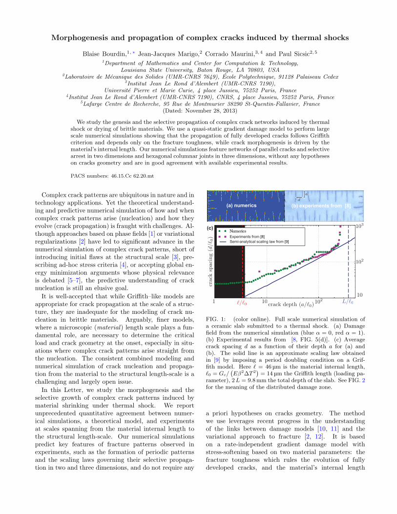
(a) numerics (b) experiments from [8]
Experiments from [8]
Numerics
Distributed
damage
Semi-analytical scaling law from [9]
(c)
FIG. 1: (color online). Full scale numerical simulation ofa ceramic slab submitted to a thermal shock. (a) Damagefield from the numerical simulation (blue α = 0, red α = 1).(b) Experimental results from [8, FIG. 5(d)]. (c) Averagecrack spacing d as a function of their depth a for (a) and(b). The solid line is an approximate scaling law obtainedin [9] by imposing a period doubling condition on a Grif-fith model. Here ℓ = 46 µm is the material internal length,ℓ0 = Gc/
(
Eβ2∆T 2)
= 14 µm the Griffith length (loading pa-rameter), 2L = 9.8mm the total depth of the slab. See FIG. 2for the meaning of the distributed damage zone.
a priori hypotheses on cracks geometry. The methodwe use leverages recent progress in the understandingof the links between damage models [10, 11] and thevariational approach to fracture [2, 12]. It is basedon a rate-independent gradient damage model withstress-softening based on two material parameters: thefracture toughness which rules the evolution of fullydeveloped cracks, and the material’s internal length
2
which controls the initial stages of crack nucleation.
We investigate the thermal shock of a brittle ceram-ics, a now classical experimental setup [3, 13, 14] where asample initially at a uniform temperature T0 is quenchedin a cold bath at temperature T0 − ∆T . We consider arectangular slab Ω exposed to the thermal shock throughits thin faces only. We focus first on very thin slabs,which we represent by a two–dimensional body in planestress. We assume that within the range of temperaturesinvolved, the material properties remain constant. De-noting by u the displacement field and ε = (∇u+∇T
u)/2the linear strain tensor, we consider for the sound mate-rial a linear elastic behavior of energy density ψt(ε) =A0(ε− ε
tht ) · (ε− ε
tht )/2 where A0 is the isotropic elastic
stiffness tensor. The inelastic deformation induced by thetime-dependent temperature field Tt is ε
tht = β(Tt−T0)I,
where I is the identity matrix. The index t is meant tohighlight the dependence on time. We neglect the cracksinfluence on heat transfer so that the temperature fieldTt solves the heat equation ∂tTt − kc∇2Tt = 0 on Ω.Phase changes, non-uniform convection and other non-linear aspects of the heat exchange between the fluid andthe sample are neglected by assuming that the temper-ature of the domain boundary exposed to the thermalshock is constant and equal to that of the water bath,i.e. Tt = T0 − ∆T . Inertial effects are not consideredbecause the diffusion velocity of the temperature fieldis much slower than the wave speed in the material atthe relevant scales in time and space. This hypothesis isuniversally accepted in the literature on thermal shockproblems [3, 4, 9, 14, 15]. We model material failure us-ing a gradient damage model characterized by the energyfunction
Et(u, α) =∫
Ω
ψt(ε)
s(α)+
Gc
4cw
(
w(α)
ℓ+ ℓ |∇α|2
)
dx, (1)
where α is a scalar damage field varying between 0 (soundmaterial) and 1 (fully damaged material), Gc is thematerial’s fracture toughness, ℓ an internal length, and
cw =∫ 1
0
√
w(s) ds a normalization constant. In a time-discrete setting, the quasi-static evolution is obtained bysolving at time ti the following minimization problemminu,α≥αi−1
Eti(u, α), where the unilateral constraint onα enforces the irreversibility condition on the damage.The compliance function s and the energy dissipationfunction w should be chosen such that (1) converges asℓ → 0 to a Griffith–like energy
∫
Ω\Γψt(ε) dx + GcS(Γ),
where S is the surface measure of the crack Γ [2, 16, 17].In this model, material interpenetration in the fully dam-aged area is possible. In all the simulations presentedhere, it can be checked a posteriori that this issue doesnot present itself. Here, we use s(α) = 1/(1 − α)2 andw(α) = α, a choice motivated by the convenience of itsnumerical implementation and specific analytical stud-ies [11, 18]. With this choice the damage model has a
stress-softening behavior and remains purely elastic with-out damage until the stress reaches the critical value:
σc :=
√
GcE w′(0)
2 cw ℓ s′(0)=
√
3GcE
8ℓ. (2)
The relation above may be used to determine the numeri-cal value of the internal length for a specific material fromthe knowledge of its elastic limit σc, Young modulus E,and fracture toughness Gc [18]. The present model is inmany aspects similar to the phase-field models of frac-ture developed independently [19]. Those with single–well dissipation potentials [1, 20] are in the form of (1)with w(α) = c(1 − g(1 − α)), where g(φ) = 4φ3 − φ4.One significant difference is that while phase-field mod-els typically involve some form of viscous regularizations,our formulation is rate-independent. In addition, the cur-rent literature based on phase-field models is concernedonly with the propagation of a pre-existing cracks anddoes not consider the initiation problem.The dimensional analysis of the energy (1) highlights
three characteristic lengths: the geometric dimensionof the domain L, the internal length ℓ and the Griffithlength ℓ0 = Gc/
(
Eβ2∆T 2)
. Using the material’sinternal length as the reference unit, the problem canbe reformulated in terms of two dimensionless param-eters, the dimension of the structure L/ℓ (a geometricparameter) and the intensity of the thermal shock ℓ0/ℓ(a loading parameter). This is a significant departurefrom the classical Griffith setting where the only relevantparameter is L/ℓ0 [4, 5, 9].
Figure 1 compares the experiment from [8, FIG. 5(d)](1mm × 9.8mm × 50mm ceramic slab, ∆T = 380 C)with the damage field from a numerical solution ofthe gradient damage model. The material properties,communicated by the authors of [8] are E = 340GPa,ν = 0.22, Gc = 42.47 Jm−2, σc = 342.2MPa, andβ = 8× 10⁻⁶ K−1, which using (2) gives ℓ = 46µmand ℓ0 = 14µm. As our model is rate independentits solution are independent of kc, up to a changeof time scale. The numerical results are obtainedthrough a finite element discretization and the approachof [2, 18, 21]. The main technical difficulties are theconstrained minimization of a non-convex energy, andthe need for a spatial discretization adapted to thematerial length-scale scale ℓ. Cracks correspond to thelocalized bands where α goes from 0 to 1 and back to0. The qualitative agreement between experiments andsimulation is very good. In particular, our simulationsreproduce the key phenomenon: the emergence of aperiodic array of parallel short cracks at the initiationand their selective propagation toward the interior ofthe slab. Figure 1(c) shows a quantitative comparisonbetween the numerical simulation of FIG. 1(a) andexperimental data from [8] by plotting the average crack
3
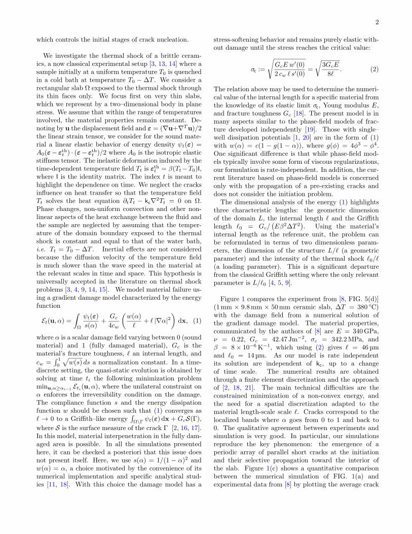
(a)
(b)
FIG. 2: (color online). Crack nucleation: (a) Damage fieldnear the shock surface before (left) and after (right) bifur-cation time t∗ for ℓ0/ℓ = 0.107 showing the bifurcation of ahorizontally-homogeneous damaged band of depth D∗ towarda periodic solution with wavelength λ∗. (b) Wavelength, timeand damage penetration in numerical simulations for severalintensities of the thermal shock ℓ0/ℓ (dots), compared to thesemi-analytical results from [23] (solid lines).
spacing d as a function of the distance a to the edgeexposed to the thermal shock for the final configuration,the agreement is striking. Note that in the experimentalresults shorter cracks are probably filtered out by theadopted experimental crack detection methods [18]. In afirst regime, very short equi-distributed cracks nucleate(the plateaus of the crack spacing for short depthin the numerical experiments), followed by selectivearrest and period doubling [22]. In the central regionof the plot, we can compare experimental and simu-lation data with a scaling law obtained in [9] throughlinear fracture mechanics calculations by imposing abifurcation condition between crack propagation modeswith period doubling or not (solid line). For largervalues of a, we observe the final crack arrest causedby the finite size of the sample, again in very goodagreement with the experiments. Whereas classicaltheories can be applied in the second and third regimesconsisting of fully developed cracks, they cannot prop-erly account for the nucleation phenomenon observedhere without preexisting flaws. Our simulations areinitialized with a null damage field, an homogenous ma-terial, and an unflawed geometry. The crack nucleationis due to the softening character of the material behavior.
The second series of simulations focuses precisely onthe crack nucleation process and hence on short times.In this setting, one can assume that the domain is semi-infinite so that the geometric parameter L/ℓ is infiniteand the only parameter is the intensity of the thermalshock ℓ0/ℓ. For an undamaged material, the stress isuniaxial and reaches its maximum value σmax = Eβ∆Tat the surface of the thermal shock. Since (σmax/σc)
2 =
3ℓ/8ℓ0, for mild-enough thermal shocks (ℓ0/ℓ > 8/3), thecritical stress is never reached and the solution remainselastic at all time. If ℓ0/ℓ < 8/3, damage takes place att = 0, is homogeneous in the horizontal direction, andnon-null in a band of finite thickness D, which pene-trates progressively inside the body until a critical timet∗. At t = t∗ the horizontally–homogeneous solution be-comes unstable and the damage field develops oscillationsof periodicity λ∗ (FIG. 2(a)). An analytical solutionfor the damage field in the first stage of the evolutionand its bifurcation and stability analysis is reported in[23], providing semi-analytical results for the periodicityλ∗, the damage penetration D∗, and the time t∗ at thebifurcation. Here we perform several simulations vary-ing ℓ0/ℓ and detect the critical parameter at the bifurca-tion. In Figure 2(b) the numerical simulations (dots) arecompared to [23] (solid lines). The good agreement pro-vides an excellent verification of our numerical model.For severe shocks (ℓ0 ≪ ℓ), the results disclose a well-definite asymptotic behavior with λ∗ ∼
√ℓ0ℓ, D
∗ ∼ ℓ,and t∗ ∼ ℓ0ℓ/kc. In this regime we observe numericallythat all oscillations at the bifurcation develop in fullyformed cracks (maxα = 1), which is not the case formilder shocks (ℓ0 ∼ ℓ). However, the full post-bifurcationanalysis remains an open problem at this time.
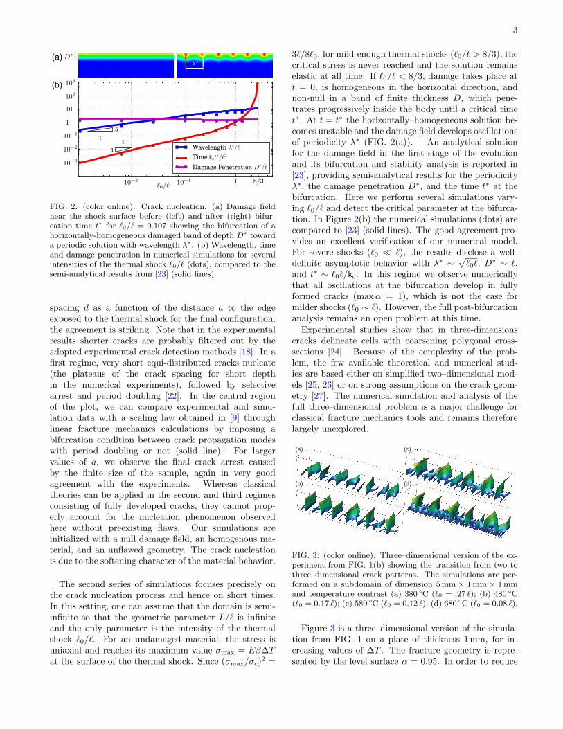
Experimental studies show that in three-dimensionscracks delineate cells with coarsening polygonal cross-sections [24]. Because of the complexity of the prob-lem, the few available theoretical and numerical stud-ies are based either on simplified two–dimensional mod-els [25, 26] or on strong assumptions on the crack geom-etry [27]. The numerical simulation and analysis of thefull three–dimensional problem is a major challenge forclassical fracture mechanics tools and remains thereforelargely unexplored.
(a)
(b)
(c)
(d)
FIG. 3: (color online). Three–dimensional version of the ex-periment from FIG. 1(b) showing the transition from two tothree–dimensional crack patterns. The simulations are per-formed on a subdomain of dimension 5mm × 1mm × 1mmand temperature contrast (a) 380 C (ℓ0 = .27 ℓ); (b) 480 C(ℓ0 = 0.17 ℓ); (c) 580 C (ℓ0 = 0.12 ℓ); (d) 680 C (ℓ0 = 0.08 ℓ).
Figure 3 is a three–dimensional version of the simula-tion from FIG. 1 on a plate of thickness 1mm, for in-creasing values of ∆T . The fracture geometry is repre-sented by the level surface α = 0.95. In order to reduce
4
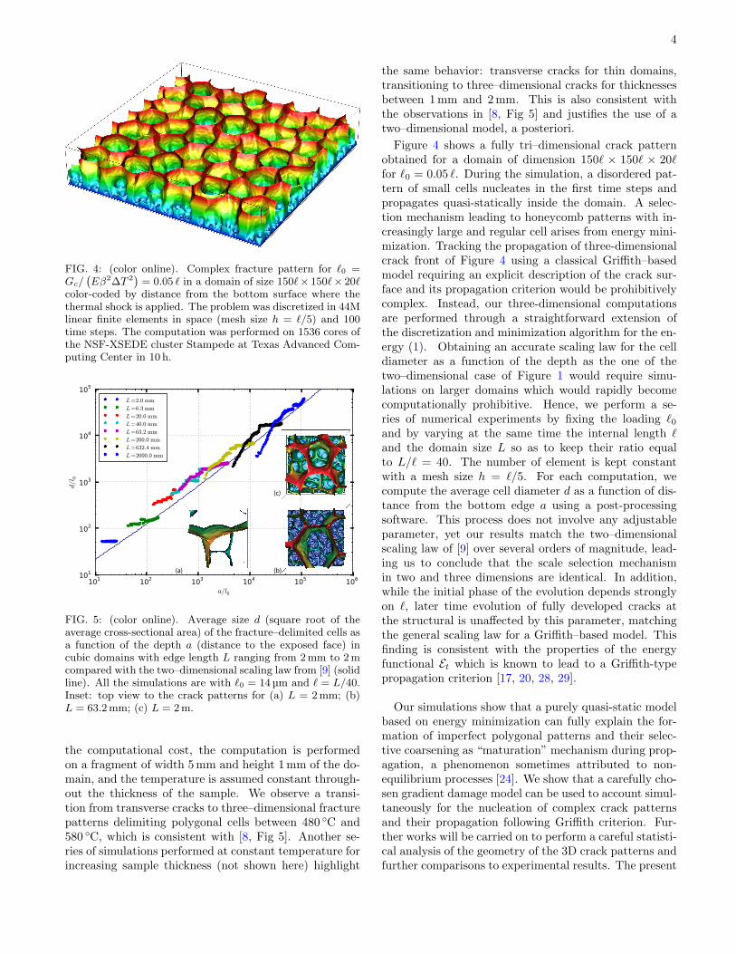
FIG. 4: (color online). Complex fracture pattern for ℓ0 =Gc/
(
Eβ2∆T 2)
= 0.05 ℓ in a domain of size 150ℓ× 150ℓ× 20ℓcolor-coded by distance from the bottom surface where thethermal shock is applied. The problem was discretized in 44Mlinear finite elements in space (mesh size h = ℓ/5) and 100time steps. The computation was performed on 1536 cores ofthe NSF-XSEDE cluster Stampede at Texas Advanced Com-puting Center in 10 h.
(a) (b)
(c)
FIG. 5: (color online). Average size d (square root of theaverage cross-sectional area) of the fracture–delimited cells asa function of the depth a (distance to the exposed face) incubic domains with edge length L ranging from 2mm to 2mcompared with the two–dimensional scaling law from [9] (solidline). All the simulations are with ℓ0 = 14 µm and ℓ = L/40.Inset: top view to the crack patterns for (a) L = 2mm; (b)L = 63.2mm; (c) L = 2m.
the computational cost, the computation is performedon a fragment of width 5mm and height 1mm of the do-main, and the temperature is assumed constant through-out the thickness of the sample. We observe a transi-tion from transverse cracks to three–dimensional fracturepatterns delimiting polygonal cells between 480 C and580 C, which is consistent with [8, Fig 5]. Another se-ries of simulations performed at constant temperature forincreasing sample thickness (not shown here) highlight
the same behavior: transverse cracks for thin domains,transitioning to three–dimensional cracks for thicknessesbetween 1mm and 2mm. This is also consistent withthe observations in [8, Fig 5] and justifies the use of atwo–dimensional model, a posteriori.
Figure 4 shows a fully tri–dimensional crack patternobtained for a domain of dimension 150ℓ × 150ℓ × 20ℓfor ℓ0 = 0.05 ℓ. During the simulation, a disordered pat-tern of small cells nucleates in the first time steps andpropagates quasi-statically inside the domain. A selec-tion mechanism leading to honeycomb patterns with in-creasingly large and regular cell arises from energy mini-mization. Tracking the propagation of three-dimensionalcrack front of Figure 4 using a classical Griffith–basedmodel requiring an explicit description of the crack sur-face and its propagation criterion would be prohibitivelycomplex. Instead, our three-dimensional computationsare performed through a straightforward extension ofthe discretization and minimization algorithm for the en-ergy (1). Obtaining an accurate scaling law for the celldiameter as a function of the depth as the one of thetwo–dimensional case of Figure 1 would require simu-lations on larger domains which would rapidly becomecomputationally prohibitive. Hence, we perform a se-ries of numerical experiments by fixing the loading ℓ0and by varying at the same time the internal length ℓand the domain size L so as to keep their ratio equalto L/ℓ = 40. The number of element is kept constantwith a mesh size h = ℓ/5. For each computation, wecompute the average cell diameter d as a function of dis-tance from the bottom edge a using a post-processingsoftware. This process does not involve any adjustableparameter, yet our results match the two–dimensionalscaling law of [9] over several orders of magnitude, lead-ing us to conclude that the scale selection mechanismin two and three dimensions are identical. In addition,while the initial phase of the evolution depends stronglyon ℓ, later time evolution of fully developed cracks atthe structural is unaffected by this parameter, matchingthe general scaling law for a Griffith–based model. Thisfinding is consistent with the properties of the energyfunctional Et which is known to lead to a Griffith-typepropagation criterion [17, 20, 28, 29].
Our simulations show that a purely quasi-static modelbased on energy minimization can fully explain the for-mation of imperfect polygonal patterns and their selec-tive coarsening as “maturation” mechanism during prop-agation, a phenomenon sometimes attributed to non-equilibrium processes [24]. We show that a carefully cho-sen gradient damage model can be used to account simul-taneously for the nucleation of complex crack patternsand their propagation following Griffith criterion. Fur-ther works will be carried on to perform a careful statisti-cal analysis of the geometry of the 3D crack patterns andfurther comparisons to experimental results. The present

5
modeling framework has a general validity and can beapplied to other domains including for example the for-mation of basalt columns with uniform cross-sectionaldiameters through the solidification of lava fronts [24] orshaping of biological systems as observed of the scaleson the heads of crocodiles [30]. We are also consideringstronger thermo-mechanical coupling including the effectof cracks on heat transfer as in [15, 31].
The authors wish to thank Yingfeng Shao for provid-ing the experimental data used in FIG. 1. B.B. work wassupported in part by the National Science Foundationgrant DMS-0909267. Some numerical experiments wereperformed using resources of the Extreme Science andEngineering Discovery Environment (XSEDE), which issupported by National Science Foundation grant num-ber OCI-1053575 under the Resource Allocation TG-DMS060014. J.J.M. and C.M. gratefully acknowledge thefunding of the ANR program T-Shock OTP J11R087.
∗ Corresponding author[1] A. Pons and A. Karma, Nature 464, 85 (2010).[2] B. Bourdin, G.-A. Francfort, and J.-J. Marigo, J. Elas-
ticity 91, 5 (2008).[3] H. A. Bahr, G. Fischer, and H. J. Weiss, J. Mater. Sci.
21, 2716 (1986).[4] E. A. Jagla, Phys. Rev. E 65, 046147 (2002).[5] D. R. Jenkins, Phys. Rev. E 71, 056117 (2005).[6] C. Maurini, B. Bourdin, G. Gauthier, and V. Lazarus,
Int. J. Fracture (2013), to appear.[7] J.-J. Marigo, J. Nonlinear Sci. 20, 831 (2010).[8] Y. Shao, Y. Zhang, X. Xu, Z. Zhou, W. Li, and B. Liu,
J. Am. Ceram. Soc. 94, 2804 (2011).[9] H.-A. Bahr, H.-J. Weiss, U. Bahr, M. Hofmann, G. Fis-
cher, S. Lampenscherf, and H. Balke, J. Mech. Phys.Solids 58, 1411 (2010).
[10] K. Pham and J.-J. Marigo, CR Mecanique 338, 199(2010).
[11] K. Pham and J.-J. Marigo, Continuum Mech. Thermo-dyn. 25, 147 (2013).
[12] G. Francfort and J.-J. Marigo, J. Mech. Phys. Solids 46,1319 (1998).
[13] C. Jiang, X. Wu, J. Li, F. Song, Y. Shao, X. Xu, andP. Yan, Acta Mater. 60, 4540 (2012).
[14] J. Geyer and S.Nemat-Nasser, Int. J. Solids Struct. 18,137 (1982).
[15] T. Boeck, H.-A. Bahr, S. Lampenscherf, and U. Bahr,Physical Review E 59, 1408 (1999).
[16] B. Bourdin, G. Francfort, and J.-J. Marigo, J. Mech.Phys. Solids 48, 797 (2000).
[17] A. Braides, Approximation of Free-Discontinuity Prob-lems, Lecture notes in Mathematics, vol. 1694 (Springer,1998).
[18] See Supplemental Material at [URL will be inserted bypublisher] for more details on the damage model, its nu-merical implementation, and the postprocessing meth-ods.
[19] A. Karma, D. A. Kessler, and H. Levine, Phys. Rev.
Lett. 87, 045501 (2001).[20] V. Hakim and A. Karma, Phys. Rev. Lett. 95, 235501
(2005).[21] B. Bourdin, Interface Free Bound. 9, 411 (2007).[22] See Supplemental Material at [URL will be inserted by
publisher] for the entire evolution from nucleation tocrack selection.
[23] P. Sicsic, J.-J. Marigo, and C. Maurini, J. Mech. Phys.Solids (2013), to appear.
[24] L. Goehring, L. Mahadevan, and S. W. Morris, Proc.Natl. Acad. Sci. USA 106, 387 (2009).
[25] E. A. Jagla and A. G. Rojo, Phys. Rev. E 65, 026203(2002).
[26] M. Jungen, Mathematical Models and Methods in Ap-plied Sciences 22, 1150006 (2012).
[27] H.-A. Bahr, M. Hofmann, H.-J. Weiss, U. Bahr, G. Fis-cher, and H. Balke, Physical Review E 79 (2009).
[28] V. Hakim and A. Karma, J. Mech. Phys. Solids 57, 342(2009).
[29] P. Sicsic and J.-J. Marigo, Journal of Elasticity 113, 55(2013).
[30] M. C. Milinkovitch, L. Manukyan, A. Debry, N. Di-Poı,S. Martin, D. Singh, D. Lambert, and M. Zwicker, Sci-ence 339, 78 (2013).
[31] P. Budkewitsch and P.-Y. Robin, Journal of Volcanologyand Geothermal Research 59, 219 (1994).