mormon slough project san joaquin county, california · pdf fileoperation and maintenance...
TRANSCRIPT

~..~--=================OPERATION AND MAINTENANCE MANUAL
FOR
MORMON SLOUGH PROJECT
SAN JOAQUIN COUNTY, CALIFORNIA
PART No. 1- LEVEES AND CHANNELSSAN JOAQUIN RIVER TO BELLOT A
Jr',..• " ..
..'"~ .~~
DEPARTMENT OF THE ARMYSACRAMENTO DISTRICT, CORPS OF ENGINEERS
SACRAMENTO. CALIFORNIA
'"7"~ ==========================-

DISPOSITION FORMFor ule of Ihls form, seeAR 340-15; the proponenl agency Is TAGO.
CMT1
River, California
FROM Ch, Engineering Div DATE 28 December 1984POTTER/lp/3572
I~ Ch, C-Ops Division
REFERENCE OR OFFICE SYMBOL SUBJECT
Mormon Slough, CalaverasAdditions to O&M Manual~ SPKED-D
1. Inclosed are two copies of additions to the operation and maintenance manual forthe Mormon Slough project, Part No.1, Levees and Channels, San Joaquin River to Bellota.The additions reflect completed construction work for the Jack Tone Road Bridge EmergencyBank Protection project.
2. A copy of the additions has been furnished to the Division Engineer. Copies of theadditions have been furnished to the Reclamation Board and the Department of WaterResources.
Incl (dupe)as
GEORGE C. WEDDELLChief, Engineering Division
cc:Civ Des Br
Civ Des Sec CCiv Des Sec D
DA FORMAUG 80 2496 PREVIOUS EDITIONS WILL BE USED
fl'u,s. Ga..ramo"t ",nUIlI Offl,,", 1113-40''''2

OPERATION AND MAINTENANCE MANUAL MORMON SLOUGH PROJECT
SAN JOAQUIN COUNTY, CALIFORNIA
PART NO. 1 LEVEES AND CHANNELS
SAN JOAQUIN RIVER TO BELLOTA
LOCATION ADDITION OR REVISION DATE Section I Add paragraph 1-01a 5 Dec 1984 Section I Add paragraph 1-03h 5 Dec 1984 Section I Add paragraph 1-05f 5 Dec 1984 Section II Add paragraph 2-02a 5 Dec 1984 Section II Add paragraph 2-03a 5 Dec 1984 Paragraph 4-03e Add subparagraphs 2(a), (b), (c), (d) 5 Dec 1984 Exhibit B Add drawing File No. SJ-4-103 5 Dec 1984 Exhibit H Add copy of letter of transfer dated 17 Apr 1984 5 Dec 1984 Exhibit F Add copy of transfer letter dated 19 Aug 1968 26 Mar 2010 Exhibit F Add copy of Summary of Mormon Slough inspection
Contract 68-0020 Unit No. 2 26 Mar 2010
Exhibit F Add copy of transfer letter dated 9 Jan 1969 26 Mar 2010 Exhibit F Add copy of Summary of Mormon Slough inspection
referenced Contract 68-0060 Unit No. 1 26 Mar 2010
Exhibit F Add copy of transfer letter dated 30 Oct 1969 26 Mar 2010 Exhibit F Add copy of Summary of Mormon Slough inspection
Contract 69-0078 Unit No. 3 26 Mar 2010
Section I Add second paragraph to section 1-02 6 Apr 2010 Section I Add Description of Additional Project Works paragraph
and paragraphs i, j, k, l to section 1-03 6 Apr 2010
Section I Add second paragraph 1-04. Protection Provided and table
6 Apr 2010
Section I Add paragraphs g, h, i, j to section 1-05 6 Apr 2010 Section III Add subparagraphs (c) and (h) to section 3-07 part g 6 Apr 2010 Section III Add subparagraphs (c) and (h) to section 3-07 part h 6 Apr 2010 Section III Add table and following paragraph to 3-07 h(3) 6 Apr 2010 Section III Add paragraphs l, m, n, o, p, q, r, s to section 3-08 6 Apr 2010 Section IV Add second paragraph to section 4-02 6 Apr 2010 Section IV Add second description paragraph and 4 following tables
in section 4-04 6 Apr 2010
Section IV Add second description paragraph, bridges table and following paragraph to section 4-05.a.1
6 Apr 2010
Section IV Add entire section 4-06. Floodwalls 6 Apr 2010 Section V Add Floodwalls paragraph to section 5-02 6 Apr 2010 Section V Add second paragraph to section 5-08 6 Apr 2010

LOCATION ADDITION OR REVISION DATE Exhibit B Add as-built number E-2060 Mormon Slough and Potter
Creek Levee Improvement Plans, in 50 pages. 6 Apr 2010
Exhibit B Add drawing named CALDEM14.DWG Upper Calaveras River Levee Improvement Plans, in 75 pages.
6 Apr 2010
Exhibit B Add drawing named ACCESS.DWG Upper Calaveras River Cherry Lane, in 4 pages.
6 Apr 2010
Exhibit B Add as-built file no. E-2059 Stockton Diverting Canal Levee Improvement Plans, in 77 pages.
6 Apr 2010
Exhibit F Add copy of letter of transfer dated 1 Jul 2003 6 Apr 2010

Paragraph
TABIE OF CONTENTS
Subject
SECTION I - INTROOUCTION
1-011-~
1-0:51-041-051-06
3-013-023-033-Q43-053-063-073-08
Authorization • • • • • • • • • • • • • • • • • • • • • • • 1Location • • • • • • • • • • • • • • • • • • • • • • • •• 1Description of the Project Works ••••••••••••• 1Protection Provided • • • • • • • • • • • • • • • • • • •• 2Construction Data and Contractor ••••••••••••• 2Flood Flows • • • • • • • • • • • • • • • • • • • • • • •• 3
SECTION II - LOCAL COOPERATION REQUffiEMENTS
Requirements of weal Cooperation • • • • • • • • • • • •• 4Assurances Provided by wcal Interests •••••••••• 4Acceptance by the State Reclamation Board • • • • • • • •• 4
SECTION III - MAINTENANCE AND OPERATION - GENERAL PROCEDURE
Reference to Approved Regulations • • • • • • • • • • • •• 5Intent of Regulations • • • • • • • • • • • • • • • • • •• 5Purpose of this Manual •• • • • • • • • • • • • • • • •• 5Definitiona • • • • • • • • • • • • • • • • • • • • • • •• 6General Provisions of Regulations • • • • • • • • • • • •• 6Assistance to be Furnished by the District Engineer • • •• 8Responsibilities of the Superintendent •••••••••• 8Inspection Procedure ••• • • • • • • • • • • • • • • • • 12
SECTION IV - FEATURES OF THE PROJECTSUBJECT TO FlOOD CONTROL REnUIATIONS
~ 4-01 Project Works • • • • • · • • • • • • • • • • • • • · • • · 14\ 4-()2 Levees 14• • • • • • • • • • • • • • · • · • • • • • • · · ·4-03 Channels and Floodways · • · • • • • • • • • • • • • • • • 19
4-04 Drainage and Irrigation Structures · · • • • • • • · · 244-05 Miscellaneous Facilities • • • • • • · • • • • • • • • • · 34
SECTION V - SOOG&STED ME:l'HOOO OF COMBATING FLOOD CONDITIONS
5-015-~
5-035-045-055-065-075-08
Methods Suggested • • • • • • • • • • • • • • • • • • • • • 39Earthen Levees • • • • • • • • • • • • • • • • • • • • • • 39Premeditated Damage • • • • • • • • • • • • • • • • • • • • 39Secl.U'"ity • • • • • • • • • • • • • • • • • • • • • • 39Inspection of Flood Control Works • • • • • • • • • • • • • 40Preliminary RePair Work • • • • • • • • • • • • • • • • • • 40Disaster Relief • • • • • • • • • • • • • • • • • • • • • • 4lFlood Fight • • • • • • • • • • • • • • • • • • • • • • • • 41
i
/
Pare.e;raph
TABIE OF CONTENTS (Cont'd)
Subject
5-095-105-11
Topping • • • • • • • • • • • • • • •Transportation •• • • • • • • • • •Use of Government Plant • • • • • • •
EXHIBrrs
• • •• • •• • •
• • • • • • • • 43· "'· "'
4Jfift!\.r
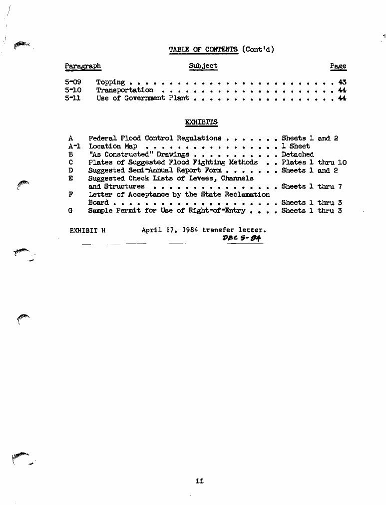
A Federal Flood. Control Regulations • • • • • • • Sheets 1 and 2A-l Location Map •••• • • • • • • • • • • • • • 1 SheetB "As Constructed" Drawings • • • • • • • • • • • DetachedC Plates of Suggested Flood Fighting Methods • • Plates 1 thru 10D Suggested Semi -Annual Report Form • • • • • • • Sheets 1 and 2E Suggested Check llsts of Levees I Channels
and Structures ••••••• • • • • • • • • • Sheets 1 thru 7F Letter of Acceptance by the State Reclamation
Board • • • • • • • • • • • • • • • • • • • • • Sheets 1 thru 3G Sample Permit for Use of Right-or-Entry •••• Sheets 1 thru 3
EXHIBIT H April 17. 1984 transfer letter.f)_~ 5-6+
ii

OPERATION AND MAINTENANCE MANUAL MORMON SLOUGH PROJECT – SAN JOAQUIN COUNTY
PART NO. 1 – LEVEES AND CHANNELS
SAN JOAQUIN RIVER TO BELLOTA
SECTION I
INTRODUCTION
1-01. Authorization. The Mormon Slough Project, San Joaquin County, California, was authorized by the Flood Control Act approved 23 October 1962 in Public Law 87-874, 87th Congress, Second Session, which states in part:
“The project for flood protection on Mormon Slough, Calaveras River, California, is hereby authorized substantially in accordance with the recommendations of the Chief of Engineers in House Document Numbered 576, 87th Congress, at an estimated cost of - - - -.”
In the report of the Chief of Engineers to the Secretary of the Army, dated 28 August 1962, the Chief of Engineers stated that he concurred in the Recommendations of the Board of Engineers for Rivers and Harbors. In paragraph 10 of House Document No. 576, the recommendations of the Board were as follows: “Recommendations . . . Accordingly, the Board recommends improvement for
flood control on Mormon Slough, the Diverting Canal, and the Calaveras River, California, consisting of channel enlargement and clearing, slope paving, levees, gated drainage structures, a pumping plant, railroad adjustments, and appurtenant works; all generally in accordance with the plan of the District Engineer and with such modifications thereof as in the discretion of the Chief of Engineers may be advisable . . . .”
1-01a Construction of emergency bank protection work along the right bank Mormon Slough at the Jack Tone Road bridge under authority of Section 14 of the 1946 Flood Control Act, as amended, was approved by the Office of the Chief of Engineers on October 29, 1981. Funding for construction was approved on December 1, 1982. 1-02. Location. The Mormon Slough Flood Control Project is located in San Joaquin County and in the general vicinity north and east of the city of Stockton, California. Channel improvement begins at the San Joaquin River and proceeds upstream on the Stockton Diverting Canal to Mormon Slough; thence upstream on Mormon Slough to Bellota, California, a total distance of about 24.5 miles. A backwater levee has been constructed on the left bank of the Calaveras River upstream from the Stockton Diverting Canal for about 0.75 miles and on the left bank of Potter Creek from Mormon Slough upstream to Jack Tone Road.
1

The project has been extended with local funding to include levee modifications along Mormon Slough, Potter Creek, Upper Calaveras River, and Stockton Diverting Canal. The project location is indicated on the vicinity map included in EXHIBIT APPENDIX -1. 1-03. Description of the Project Works. The three pumping plants are covered under another manual designated Part No. 2. The project works covered by this manual (Part No.1) include the following:
a. The improved channel and levees along both banks of the Calaveras River from the Stockton Deep Water Ship Channel to its junction with the Stockton Diverting Canal, a distance of about 5.7 miles.
b. The improved channel and levee along both banks of the Calaveras River
from the Stockton Diverting Canal to the McAllen Road, a distance of about 0.6 miles.
c. The improved channel and levees along both banks of the Stockton Diverting
Canal from the Calaveras River to its junction with Mormon Slough, a distance of about 5.0 miles.
d. The improved channel and levees along both banks of Mormon Slough from
the Diverting Canal to Potter Creek, a distance of about 2.3 miles.
e. The improved channel and levee along the left bank of Potter Creek from the Mormon Slough to the Jack Tone Road, a distance of about 0.9 miles.
f. The improved channel and intermittent spoil dikes and levees along Mormon
Slough from Potter Creek to Bellota, a distance of about 11.2 miles.
g. Intermittent irrigation and drainage structures and intermittent bank protection along the above described levees and channels.
h. Gabion bank protection on the right bank of Mormon Slough at Jack Tone
Road Bridge under authority of Section 14 of the 1946 Flood Control Act, as amended.
Description of Additional Project Works. The original Mormon Slough project works are described in “Operations and Maintenance Manual for Mormon Slough Project San Joaquin County, California, Part No. 1 – Levees and Channels San Joaquin River to Bellota” U.S. Army Corps of Engineers, Sacramento, California 1970, and “Operations and Maintenance Manual for Mormon Slough Project San Joaquin County, California, Part No. 2 – Pumping Plants” U.S. Army Corps of Engineers, Sacramento, California 1970. Additional project works added through this addendum include the following:
2

i. Improvement of levees on both banks of the Mormon Slough upstream from the Stockton Diverting Canal to the confluence with Potter Creek. The right bank of Mormon Slough has been modified 400 feet upstream from its confluence with Potter Creek.
j. Improvement of levee on left side of Potter Creek from Mormon Slough to
Jack Tone Road.
k. Improvements of levee on both sides of Stockton Diverting Canal from the Mormon Slough northwest to the confluence with the Upper Calaveras River. Intermittent floodwall construction on the right bank along the same reach.
l. Improvements of Levee on both sides of Upper Calaveras River from the
junction with the Stockton Diverting Canal to the Central California Traction railroad tracks.
1-04. Protection Provided. The project provides flood protection from flood flows on
the Calaveras River, Mormon Slough, the Stockton Diverting Canal and Potter Creek to adjacent agricultural lands consisting of about 37,000 acres of orchards, vineyards and cultivated fields; the city of Stockton; three mainline railroads, two local railroads and one branch line; US Highway 99 and numerous State highways and County roads. The project design flow for Mormon Slough is 12,500 cubic feet per second; for Potter Creek 1,000 cubic feet per second; and for the Stockton Diverting Canal and lower reach of the Calaveras River 13,500 cubic feet per second. For the project levees, at least 3 feet of freeboard has been provided over the project design flood plane. The adopted flood plane for Mormon Slough varies from elevation 124.1 at the upper end near Bellota to elevation 44.5 at the Stockton Diverting Canal; for the Stockton Diverting Canal the adopted flood plane varies from elevation 44.5 at Mormon Slough to elevation 24.8 at its junction with the Calaveras River; for the Calaveras River the adopted flood plane varies from 24.8 at the Diverting Canal to elevation 7.4 at its junction with the San Joaquin River; for Potter Creek the adopted flood plane varies from elevation 57.8 at Jack Tone Road to elevation 51.2 at Mormon Slough. All elevations refer to mean sea level datum, 1929 adjustment.
For the additional project works, the peak design flows at various location and corresponding 100-yr. floodplain elevations are indicated in the following table: 3

Segment Location Peak Design Flow (cfs)
100-Yr Floodplain Elevation (ft)
Upper Calaveras River
Highway 99 1,176 31.8
Stockton Diverting Canal
Main Street 14,843 39
Stockton Diverting Canal
Hwy 99 Bridge 14,817 33
Mormon Slough At Potter A 15,143 54 Potter Creek Jack Tone Road 1,319 59.9
For additional project works 3.3 feet of freeboard has been provided over the project design floodplain for all areas in which the levee was raised. 1-05. Construction Data and Contractor. Work required by the Corps of Engineers to
bring the levees on the Mormon Slough Project to project standards and to excavate the channels was accomplished under the following contracts:
a. Channel improvement from Jack Tone Road to Bellota was accomplished
under Contract No. DACW05-68C-0060 by H. Earl Parker, Inc. during the period from 8 April 1968 to 13 January 1969. Specification No. 3321, Drawing No. CA-4-48.
b. Levee construction and channel improvement from the mouth of the Stockton
Diverting Canal to Jack Tone Road was accomplished under Contract No. DACW05-68C-0020 by R.P. Burrus during the period from 3 October 1967 to 15 August 1968, Drawing No. 3-4-147.
c. Railroad relocation for the Southern Pacific Railroad and Stockton Terminal
& Eastern Railroad was accomplished under Contract No. DACW05-68C-0074 by Hertel Construction Co. during the period from 24 April 1968 to 30 September 1968. Specification No. 3486, Drawing No. CA-5-56.
d. Levee crown surfacing and bank protection from the mouth of the Calaveras
River upstream to McAllen Road bridge was accomplished under Contract No. DACW05-69-C-0078 by Claude C. Wood Co. during the period from 17 June 1969 to 16 October 1969. Specification No.3600, Drawing No.3-4-148.
e. Bank protection and structure modifications on Mormon Slough from the
mouth of Potter Creek upstream to Bellota was accomplished under Contract No. DACW05-70-C-0036 by E.W. Eldridge and Roy D. Garren Jr. during the periodfrom 10 October 1969 to 12 May 1970. Specification No. 3642A, Drawing No. CA-13-60.
f. Section 14 emergency bank protection along Mormon Slough right bank at
Jack Tone Road Bridge was accomplished on April 13, 1984 under Contract
3a

DACW05-84-C-0041 by James Ferry Construction, AJV, James L. Ferry & Sons, Inc. and James L. Ferry, Jr. – Specification No. 6844, Drawing File No. SJ-4-103.
Construction required to bring the additional project works described in this addendum to project standard was accomplished under the following contracts: g. Levee modification along both banks of the Mormon Slough and the left bank
of Potter Creek was accomplished by Teichert Construction, during the period from August 1997 to October 1998.
h. Levee modification on both banks of the Stockton Diverting Canal and
floodwall construction was accomplished by Teichert Construction, during the period from August 1997 to October 1998.
i. Levee modification on both banks of the Upper Calaveras River was
accomplished by Teichert Construction, during the period from January 1998 to October 1998.
j. Bridge parapet modifications and floodproofing for Cal-Trans Bridges was
accomplished by Benco Construction, during the period from April 1998 to October 1998.
1-06. Flood Flows. For purposes of this project, the term “Flood” or “high water period” for Mormon Slough shall refer to flows when the water surface in the stream reaches or exceeds the reading of 12.0 on the gage located on the left bank of the Mormon Slough near Bellota and approximately 1,400 feet upstream from the Escalon-Bellota Road. (This stage reading corresponds to a flow of about 10,000 cfs in Mormon Slough at the gage)
3b
SECTION II
LOCAL COOPERATION REQUIR~M!:NTS
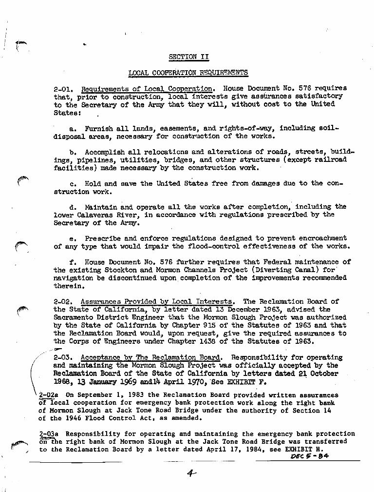
2-01. Requirements of Local Cooperation. House Do~nt No. 576 requiresthat, prior to construction, local interests give assUrances satisfactoryto the Secretary of the Army that they Will, without cost to the UnitedStates:
a. Furnish all lands, easements, and rights-of-way, including soildisposal areas, necessary for construction of the works.
b. Accomplish all relocations and alterations of roads, streets, bUildings, pipelines, utilities, bridges, and other structures (except railroadfacilities) made necessary by the construction work.
c. Hold and save the United States free from da.nages due to the construction work.
. .d. Maintain and operate all the 'Works after completion, inclUding the
lower Calaveras River, in accordance with regulations prescribed by theSecretary of the Army.
e. Prescribe and enforce regulations designed to prevent encroachmentof any type that would impair the flood-control effectiveness of the works.
f. House Document No. 576 further requires that Federal maintenance ofthe existing Stockton and Mormon Channels Project (Diverting Canal) for'naVigation be discontinued upon. completion of the improvements recommendedtherein.
2-02. Assurances Provided by Local Interests. The Reclarna.tion Board ofthe State of California, by letter dated 13 December 1963, advised thesacramento District Engineer that the Mormon Slough Project was authorizedby the State of California by Chapter 915 of the Statutes of 1963 and thatthe Reclamation Board 'Would, upon request, give the required assurances tothe Corps of Engineers under Chapter 1438 of the Statutes of 1963•
.,/ 2-03. Acceptance by The Reclamation Board. Responsibility for operating
(
and maintaining the Mormon Slough Project was officially accepted by theReclamation Board of the State of California by letters dated 21 October
. 1968, 13 J8Z!UBZY 1969 and14 AprU 1':170, 'See EXHIBIT F. .
\i-02a On September 1, 1983 the Reclamation Board provided written assurancesof iocal cooperation for emergency bank protection work along the right bankof Mormon Slough at Jack Tone Road Bridge under the authority of Section 14of the 1946 Flood Control Act, as amended.
2-03a Responsibility for operating and maintaining the emergency bank protection~rFihe right bank of Mormon Slough at the Jack Tone Road Bridge was transferredto the Reclamation Board by a letter dated April 17, 1984, see EXHIBIT H.
DEC ~-84

~\
Sl]CTION III
MAINTENANCE AND OPERATION - mmERAL PROCErxrnE
3-01. Reference to Approved Regulations. This manual is submitted inaccordanc.e with provisions of Title :3:3 - Navigation and Navigable Waters,as of 1 January 1962, Chapter II, Corps of Engineers, Department of theArmy, Part 208 - Flood Control Regulations, Maintenance and Operation ofFlood Control Works, a capy of which is included as Exhibit A, Sheets1 and 2.
:3-02. Intent of Regulations. The general intent of the regulationsapproved by the Secretary of the Army is stated in paragraph 208.10(a)(1)as follows: "The structures and facilities constructed by the UnitedStates for local flood protection shall be continuously maintained insuch a manner and operated at such times and for such periods as may benecessary to obtain the maximum benefits."
The principle mission of the Corps of Engineers, during flood emergencies, is to insure that flood control works are properly operated andmaintained and offer technical advice to enable local interests to obtainmaximum flood protection. All other matters become secondary and willyield precedence to the accomplishment of the above-stated missions.During flood periods local interests maintain close liaison with the officeof the District Engineer, Corps of Engineers. However, in the event itis evident that all available county and local resources are inSUfficientto cope with the situation and the necessity for an emergency proclarrationis anticipated, requests for State assistance in flood fighting shouldproperly be made direct to the Department of Water Resources, which isthe State agency designated by the Director of Public Works, to receiverequests from local agencies for assistance in flood fighting. Thisagency is authorized to request Federal assistance from the Corps of ~ngi
neers when State and local resources are insufficient to cope with thesituation. Therefore, it is desired to emphasize that requests for Federal assistance in flood fighting should be made only when it is evidentthat County, state and/or other local equipment and manpower will beexhausted and local resources are inSUfficient to cope with the floodemergency situation.
:3-0:3. Purpose of this Manual. In view of the large number of localflood protection projects authorized by Congress and the repetitiousnature of regulations to govern maintenance and operation of each ioo.ividual project, and in order that local interests may be fully avare ofthe extent of the obligations asswned by them in fUrnishing assurancesof local cooperation for projects to be constructed in the :future, thegeneral regulations described above were established by the Secretary ofthe Army. The general regulations approved by the Secretary of the Arm:!,August 1944, were intended to be SUfficiently broad in scope and generalin nature as to be applicable to all flood protection projects for whichsuch regulations are required by law.
5

Section 208.l0(a)(lO) of the regulations read as follows: TheDepartment of the Army will furnish local interests with an Operationand Maintenance M:l.nual for each conpleted project, or separate usefulpart thereof, to assist them in carrying out their obligations underthis part. I! This manual has, therefore, been prepared to furnish localinterests with information on the project works and advise as to thedetails of the operation and maintenance requirements applicable to thisparticular project, to state procedure required by the Department of theArrrry, and to indicate satisfactory methods of floodfighting operationsand emergency repairs. The project works are to be mintained and operated in accordance with the Flood Control Regulations referred to aboveand interpretations thereof contained herein.
:3-04. Definitions. The Reclamation Board is the State agency whichprovided the assurances for the project; The Department of Water Resourcesis the responsible State agency who has supervisory power over the mainten- ~ance and operation of the flood control project; The assurer shall desig-nate a local agency to act for the assurer and 1mp1enent the instructionscontained herein; This agency shall hereinafter be designated as the "Superintendent.1! The term "District Engineer" shall be defined to mean theDistrict Engineer of the US Army 'Engineer District, Se.cranento, or hisauthorized representative. The term "flood" shall mean any flow in MormonSlough when the water surface reaches or exceeds the reading of 12.0 onthe California Department of Water Resources gaging station located on ~
the left bank 1,400 feet upstream from the Escalon-Bel1ota Road. Theterm "right bank" or "left bank" shall be defined to mean the right orleft bank or side, respectively, of a stream or channel when facing down-stream.
:3-05. General Provisions of Regulation. In addition to that quoted inparagraph :3-02 above, the general provisions of the Flood Control Regu-lations, contained in paragraphs 208 .10( a)( 2), to 208. lO( a)(9), both ~inclusive, are quoted as follows:
(2) The State, political SUbdivision thereof, or otherresponsible local agency, which furnished assurancethat it will maintain and. operate flood controlworks in accordance with regulations prescribed bythe Secretary of the Army, as required by law, shallappoint a permanent committee consisting of, orheaded by an official hereinafter called the "SUperintendentll
, who shall be responsible for the development and maintenance of, and directly in charge ofan organization responsible for structures and facilities during flood periods and for continuous inspection and maintenance of the project works duringperiods of low water, all without cost to the UnitedStates.
6

(3) A reserve supply of materials needed during a floodemergency shall be kept on hand at all times.
(4) No encroachment or trespass which will adverselyaffect the efficient operation or maintenance ofthe project works shall be permitted upon therights-of-way for the protective facilities.
(5) No improvement shall be passed over, under orthrough the walls, levees, improved channels orfloodways, nor shall any excavation or construction be permitted within the limits of the project right-of-way, nor shall any change be madein any feature of the works without prior determination by the District Engineer of the Department of the~ or his authorized representativethat such improvements, excavation, construction,or alteration will not adversely affect the functioning of the protective facilities. Suchimprovements or alterations as may be found to bedesirable shall be constructed in accordance withstandard engineering practice. Advice regardingthe effect of proposed improvements or alterationson the functioning of the project and infornationconcerning methods of construction acceptableunder standard engineering practice shall be obtained from the District Engineer, or, if otherwise obtained, shall be submitted for his approval.Drawings or prints showing such improvements oralterations as finally constructed shall be furnished the District Engineer after completion ofthe works.
( 6) It shall be the dUty of the Superintendent tosubmit a semi-annual report to the District Engineer covering inspection, maintenance, and operation of the protective works.
(7) The District Engineer or his authorized representative shall have access at all times to allportions of the protective works.
(8) J.aintenance measures or repairs which the District~ngineer deems neceseary, shall be promptlytaken or made.
7

(9) Appropriate measures shall be taken by local authorities to insure that the activities of all localorganizations operating pUblic or private facilitiesconnected with the protective works are coordinatedwith those of the SUperintendent's organizationduring flood periods.
3-06. Assistance to be Furnished by the District Engineer. The DistrictEngineer will:
a. Furnish the State ReclanBtion Board "As Constructed" drawings ofthe project works at the time they are transferred.
b. M:Lke periodic inspections of the project works and notify theState Reclamation Board of any repairs or maintenance measures 'Whichthe District Engineer deems necessary in addition to measures taken bythe SUperintendent.
c. SUbmit to the Office, Chief of Engineers, all cases of noncompliance with full details thereof for determination of corrective measuresto be taken.
d. Make prior determination that any proposed encroachment, improve-ment, excavation, or construction within the right-of-way, or alteration ~
of the project works, will not adversely' affect the functioning of theprotective facilities.
e. Assist local interests as may be practicable, in their duties ofascertaining storm developments having flood-producing potentialities,assembling flood-fighting forces and materialS, and initiating and carrying out fiood-fighting operations to the extent permitted by existinglaws and regulations.
3-07. Responsibilities of the Superintendent. In line with the provisions of the Flood Control Regulations, the general duties of the Superintendent include the following:
a. Trainine; of Key Personnel. Key personnel shall be trained inorder that regular maintenance work may be performed efficiently and toinsure that unexpeeted problems related to flood control may be handledin an expeditious and orderly manner. The Superintendent should haveavailable the names, addresses, and telephone numbers of all his key menand a reasonable number of substitutes. These key men should, in turn,have similar data on all of the men who will assist them in the dischargeof their duties. The organization of key men should inclUde the following:
8

(l) An assistant to act in the place of the Superintendent incase of his absence or indisp.osition.
(2) Sector foremen in sUfficient nwnber to lead maintenancepatrol work of the levee, inspect the channel, and operate the gatestructures properly during flood periods. High qualities of leadershipand responsibility are necessary for their positions.
b. Files and Records. The Superintendent shall maintain a file ofreports, records, and drawings concerning the project works, readilyavailable at all times to the District Engineer.
c. Encroaclunent or Trespass on Right-of-way. In accordance withthe provisions of Flood Control Regulations 208 .10(a)( 4), no encroachment or trespass which will adversely affect the efficient operationor maintenance of the project works shall be perm!tted on the rightsof-way for the protective facilities. The Superintendent will, therefore, cause notices to be posted at conspicuous places along the projectright-of-way directing public attention to this regulation. The Superintendent shall take whatever action is necessary under his own authorityto remove any unauthorized encroachment or to prosecute the trespassers.Some encroachment permits (landscaping and fencing) have been granted tovarious owners along the lower reaches of the Calaveras River by theReclamation Board, see paragraph 4-02c(4) of this manual.
d. Permits for RiPiht-of-entry or Use of Portion of Right-of-way.Permits for temporary right-of-entry or use of portion of the right-ofway shall not be issued without prior determination by the State Reclamation Board sufficiently in advance of issuance to permit adequate studyand consideration and determination of conditions to be embodied in thepermit document.
e. Permits for Improvements or Construction within the ProjectRight-Of-way. All requests for permits for construction of any improvements of any nature within the limits of the project right-of-way shallbe referred to the District Engineer through the State ReclaDation Boardfor determination that such construction will not adversely affect thestability, safety, and functioning of the protective facilities, and fordefinition of conditions under which permit should be granted. Theseconditions will include, among others, the following items:
( 1) That all work shall be performed:
(a) In accordance with standard engineering practice;drawings or prints of proposed improvements or alterations to the existing flood control works must be submitted for apProval to the DistrictEngineer sufficiently in advance of the proposed construction to permitadequate study and consideration of the work.
9

(b) To the satisfaction of the District Engineer. (2) After completion of the work, “As Constructed” drawings of prints, in duplicate, showing such improvements as finally constructed shall be furnished the District Engineer.
f. Coordination of Local Activities. In accordance with the provisions of Flood Control Regulations, paragraph 208.10(a)(9), the Superintendent will, during periods of flood flow, coordinate the functions of all agencies, both public and private, that are connected with the protective works. Arrangements shall be made with the local law enforcement agencies, street departments, and railroad and utility companies for developing a coordinated flood-fighting program; and an outline of this program shall be filed with the District Engineer.
g. Inspection.
(1) Flood Control Regulations, paragraph 208.10(b)(1), 208.10(c)(1) and 208.10(h)(1), are quoted in part as follows:
“(b) Levees (1) Maintenance . . . Periodic inspections shall be made by
the Superintendent to insure that . . . . maintenance measures are being effectively carried out . . . Such inspections shall be made immediately prior to the beginning of the flood season, immediately following each major high water period, and otherwise at intervals not exceeding 90 days and such intermediate times as may be necessary to insure the best possible care of the levee.”
“(c) Flood walls (1) Maintenance. Periodic inspections shall be made by
the Superintendent to be certain that . . . . maintenance measures are being effectively carried out . . . . Such inspections shall be made immediately prior to the beginning of the flood season, immediately following each major high water period, and otherwise at intervals not exceeding 90 days.
“(h) Miscellaneous facilities (Bridge Parapets and Retaining Walls) (1)
Maintenance. Miscellaneous structures and facilities constructed as a part of the protective works and other structure and facilities which function as a part of or affect the efficient functioning of the protective works, shall be periodically inspected by the Superintendent……”
(2) For sake of uniformity, and to the extent practicable, the dates of inspection shall be as follows: 1 November, 1 May, and immediately following each flood flow in excess of a reading of 12.0 on the State Department of Water Resources gage located on the left bank of Mormon Slough just upstream from the Escalon-Bellota Road.
10

(3) The suggested check lists and instructions shown in EXHIBIT E, Sheets 1 to 7 inclusive, should be followed in each inspection to insure that no features of the protective system are overlooked. Check lists locally typed or printed in conformity with sheets 2, 4 and 6 shall have printed on the reverse side of the applicable instructions shown on sheets 3, 5 and 7 EXHIBIT E. Carbon copy of the inspector’s original field notes as recorded on the check list shall be transmitted to the District Engineer immediately following each inspection, and one copy included as an enclosure to the semi-annual report as provided in paragraph 3-07(i)(1) of this manual.
h. Maintenance.
(1) Flood Control Regulations, paragraph 208.10(b)(1), 208.10(c)(1) and 208.10(h)(1), are quoted in part as follows: “(b)(1) Maintenance. The Superintendent shall provide at all times such
maintenance as may be required to insure serviceability of the structures in time of flood. Measures shall be taken to promote the growth of sod as required, . . . exterminate burrowing animals, and to provide for . . . removal of wild growth and drift deposits, and repair of damage caused by erosion or other forces . . . Immediate steps will be taken to correct dangerous conditions disclosed by such inspections. Regular maintenance repair measures shall be accomplished during the appropriate season as scheduled by the Superintendent.”
“(c) Flood walls – (1) Maintenance. Measures to eliminate encroachments
and effect repairs found necessary by such inspections shall be undertaken immediately. All repairs shall be accomplished by methods acceptable in standard engineering practice.”
“(h) Miscellaneous facilities (Bridge Parapets and Retaining Walls)(1)
Maintenance. Damaged or unserviceable parts shall be repaired or replaced without delay.” It is the Bridge Owner’s responsibility to clean debris that affects the bridge openings. The Flood Control District Superintendent will only take action if the restriction caused by the debris affects the safety and functionality of the flood control channel. Please refer to O&M Manual, page 37, item b. (3).
(2) Full responsibility for making the repairs and the methods used is placed
on the Superintendent but the experience and facilities of the District Engineer will be available to him for advice and consultation.
(3) All repairs shall be made in accordance with standard engineering
practice, to line and grade and in accordance with details shown on the construction drawings for the project works, copies of which are included
11

in EXHIBIT B. No change or alteration shall be made in any feature of the project works without prior determination by the District Engineer that such alteration will not adversely affect the stability and functioning of the protective facilities. Plans and specifications of all changes or alterations that may be proposed by the Superintendent shall be submitted to the District Engineer for investigation and approval before prosecution of the work.
Effort shall be made to maintain the original design roughness in each channel segment the original design roughness for each segment is included in the following table:
Segment Approximate Stations
Channel Manning’s
n-value
Start Location Stop Location
Diverting Canal 0+00 – 258+00 0.030 Confluence with
Upper Calaveras River
Confluence with Mormon Slough
Mormon Slough 330+00 – 496+56 0.030 Confluence with
Stockton Diverting Canal
Confluence with Potter Creek
Potter Creek 0+00 – 49+30 0.030 Confluence with
Potter Creek Jack Tone Road
Upper Calaveras River
308+00 – 338+00 0.030 Confluence of Diverting Canal and Calaveras River
1000 ft Downstream of McAllen Road
338+00 – 384+00 0.040 1000 ft Downstream of McAllen Road
700 ft Downstream of Hwy 99
384+00 – 391+00 0.050 700 ft Downstream of Hwy 99
Highway 99 Bridge
391+00 – 450+00 0.030 Highway 99 Bridge
Central California Traction Railroad
450+00 – 460+00 0.035 Central California Traction Railroad
Maintenance Reach Area
460+00 – 497+47 0.040 Maintenance Reach Area
Maintenance Reach Area
497+47 – 497+97 0.035 Maintenance Reach Area
Solari Ranch Road
Lower Calaveras River
0+00 – 191+45 0.035 Confluence with San Joaquin River
Pacific Avenue
191+45 – 293+00 0.030 Pacific Avenue Confluence of Diverting Canal and Calaveras River
12

All maintenance and any wildlife and habitat mitigation measures undertaken in connection with the additional project works will be accomplished in accordance with the Final Environmental Impact Report, Final Supplemental Environmental Impact Report, and the Findings Mitigation Monitoring Program and Statement of Overriding Considerations for this project. These documents are on file with the San Joaquin Area Flood Control Agency.
i. Reports. (1) Semi-Annual Report. The Department of Water Resources shall submit within a 10-day period following 1 December and 1 June of each year, a semi-annual report to the District Engineer covering inspection, maintenance, and operation of the protective works. This report will present a statement of:
(a) The physical conditions of the protective works as summarized from the logs of inspection
(b) Flood occurrences and behavior of the protective works, and
flood-fighting activities during the period.
(c) Prosecutions for encroachment or trespass.
(d) Permits issued for right-of-way or use of right-of-way.
(e) Permits issued for improvements or construction within the project right-of-way.
(f) Maintenance measures taken; nature, date of construction, and
date of removal of temporary repairs; date of permanent repairs.
(g) Fiscal statement of cost of maintenance and operation for the period.
A suggested form for submission of the semi-annual report is included as EXHIBIT D, Sheets 1 and 2.
3-08. Inspection Procedure. Since the enactment of State Legislation of Chapter 1528, Statutes of 1947, the Department of Water Resources, State of California, has made semi-annual inspections of all levees of authorized flood control projects in the Sacramento-San Joaquin drainage basin pursuant to the Federal Regulations as of 1 January 1962 (Title 33) and reports its findings to the local agency, the State Reclamation Board and the District Engineer of the U. S. Army Engineer District, Sacramento. At the discretion of the responsible State agency which provided the assurances for the project, the report submitted pursuant to Chapter 1528, Statutes of 1947 by the Department of Water Resources may be considered to fulfill the requirements of paragraph 3-07i above
13

provided the report complies with all provisions of that paragraph and provided the State Reclamation Board so indicates in writing to the District Engineer. The following procedure is used in inspecting the levees of the responsible maintaining agency: Personnel of the State Department of Water Resources make a detailed inspection of the levees in the spring and fall of each year and note any required maintenance. The levee inspection objectives are to determine if the following items, which are a condensation of Federal Regulations, are being adhered to:
a. That all brush, trees and wild growth other than sod are removed from levee crown and slopes.
b. That all weeds, grass and debris on the levee have been burned during the
appropriate season, where not dangerous or impractical.
c. That all grass and weeds on the levee have been mowed where removal by burning is dangerous or impracticable. This applies only on peat levees or where burning would constitute a hazard to improvement.
d. That all burrowing animals have been exterminated.
e. That all caves, sloughs, burrows, holes, slips, or other damaged portions of the
levee has been repaired.
f. That all irrigation and drainage structures through the levees are in good working condition.
g. That no revetment work or riprap have been displaced, washed out or removed.
h. That the crown of the levee is well shaped and maintained, and that unauthorized
vehicular travel is restricted.
i. That stock grazing on the levee is restricted to conditions and seasons when the levee would not be seriously scarred or otherwise damaged thereby.
j. That encroachments are not being erected on the levee which would hinder travel
by authorized patrol vehicles.
k. Prevent the erection of structures on, additions to, or alterations of, the levee unless authorized by permit from the State Reclamation Board.
This section shall be amended to include inspection and subsequent report of inspection of floodwalls, bridge parapets, and retaining walls. The following items shall be included as floodwall, bridge parapet and retaining wall items to be inspected:
13a

l. That no seepage is occurring under the structure, no soil piping or undue
settlement has occurred which affects the stability of the wall and no trees exist, the roots of which might extend under the wall and offer accelerated seepage paths.
m. That concrete is maintained such that cracking, chipping, or breaking is not
occurring to an extent which might affect the stability of the wall.
n. That encroachments are not being erected which might endanger the structure or hinder its functioning in time of flood.
o. That trash and debris adjacent to walls is removed periodically and that no fires
are built near floodwalls.
p. That no bank caving or bed scour conditions riverward of the wall exists which might endanger its stability.
q. That trash and debris are removed periodically from bridge openings. Please refer
to O&M Manual, page 37, item b. (3).
r. That rock slope protection (revetment) is inspected and replaced as necessary as described under section 4-03.e.1 of the original Operations and Maintenance Manual for Mormon Slough Project.
s. That graffiti or other improper markings are removed from concrete surfaces at
the discretion of the Flood Control District. Following this detailed inspection, a joint field inspection is made by the Superintendent and representatives of the State Department of Water Resources to review and discuss the inspection report. Upon completion of the fall inspection the State Department of Water Resources publishes an annual report entitled, “Status of Project Levee Maintenance” which indicates the degree of proficiency attained by each obligated local agency in providing required maintenance.
13b

SECTION IV
FEATURES OF THE PROJECT SUBJECT TO FLOOD CONTROL REGULATIONS
4-01. Project Works. Construction on the Mormon Slough Project consists of channel improvement extending from the San Joaquin River to high ground at Bellota, intermittent levees, spoil banks, irrigation and drainage structures and intermittent bank protection. For further details see the drawings of EXHIBIT B. 4-02. Levees. a. Description. Levees have been built along the Calaveras River, Stockton Diverting Canal, Potter Creek and at intermittent locations along Mormon Slough. Existing levees along both banks of the Calaveras River, along the left bank of the Diverting Canal and along the right bank of Mormon Slough upstream from Tobacco Road for a distance of about 2.6 miles have been provided with access ramps and crown surfacing. New levees have been built to adopted grade and section with a 12-foot crown width and side slopes of 1 on 3 waterside and 1 on 2 landside. The patrol road surfacing consists of 4 inches of crushed mineral aggregate 10 feet in width. Surfaced access ramps and the necessary turnouts and turnaround have been provided. For more complete detail of items included in construction of the above-mentioned levee, refer to the “As Constructed” drawings of EXHIBIT B. Regulations regarding inspection, maintenance and operation will be found in paragraphs 4-02b, 4-02c, and 4-02d of this manual. Levee modifications, and new levees for most additional works have been constructed to adopted grade and section with 12-foot crown width and side slopes of 1 on 3 waterside and 1 on 2 on the landside. Existing levees have been raised over 3 feet in some locations to provide the designed 3.3 feet of freeboard. In situations where existing levees have been raised, the top 6 inches of the existing levee has been sacrificed and re-compacted after stripping. For levee fill sections in locations where the levee needed to be raised more than 1 foot, minimum 2 foot bench cuts were used on the landside to support the fill. A 3 foot keyway was constructed on the landside for required fills less than or equal to 1 foot. A 12 foot keyway was constructed on the landside for required fills of greater than 1 foot. A minimum 4 inch aggregate base course has been included on top of the levees. Newly constructed levees were constructed according to the descriptions in the original operations and maintenance manuals. For more complete detail of items included in construction of the aforementioned levee modifications and new levees, refer to the As Constructed Drawings which are on file with the San Joaquin Area Flood Control Agency. b. Inspection. (1) Pertinent Requirements of the Code of Federal Regulations. Flood Control Regulations, paragraph 208.10 (b)(1), are quoted in part as follows:
14

“(b) Levees – (1) Maintenance . . . Periodic inspection shall be made by the Superintendent . . . to be certain that (i) No unusual settlement, sloughing or material loss of grade or levee cross section has taken place; (ii) No caving has occurred on either the landside or the Riverside of the levee which might affect the stability Of the levee section; (iii) No seepage, saturated areas, or sand boils are occurring.
14a
~
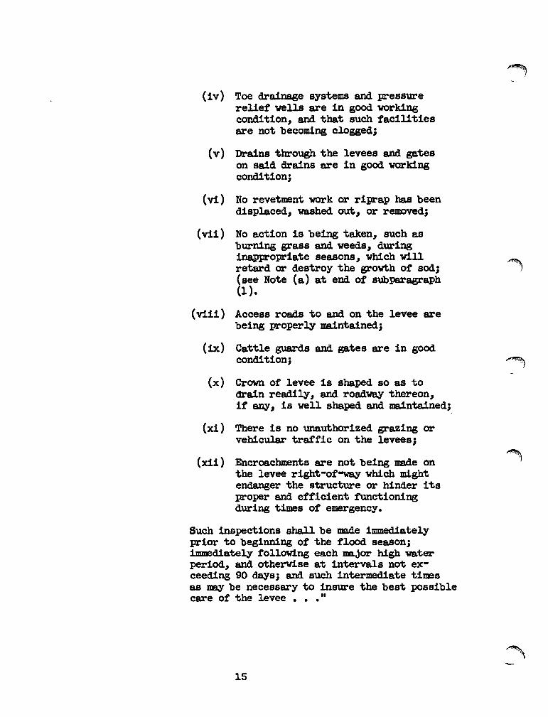
(iv) Toe drainage systems and pressurerelief wells are in good. workingcondition, and that such facilitiesare not becoming clogged;
(v) Drains through the levees and gateson said drains are in good workingcondition;
(vi) No revetment work or riprap has beendisplaced, washed out I or removed;
(vii) No action is being taken, such asburning grass and weeds, duringinappropriate seasons, which will
~retard or destroy the growth of sod;(see Note (a) at end of subParagraph(1 ).
(viii) Access roads to and on the levee arebeing properly maintained;
(ix) Cattle guards and gates are in goodcondition; ~
(x) Crown of levee is shaped so as todrain readily, and roadway thereon,if anyI is well shaped and maintained;
(xi) There is no unauthorized grazing orvehicular traffic on the levees j
(xii) Encroachments are not being made on ~the levee right-of-way which mightendanger the structure or hinder itsproper and efficient fUnctioningduring times of emergency.
Such inspections shall be made immediatelyprior to beginning of the flood season;~diately following each major high waterperiod, and otherwise at intervals not ex-ceeding 90 days; and such intermediate timesas JIlBY be necessary to insure the best possiblecare of the levee • • • II
'-15
Note (a)
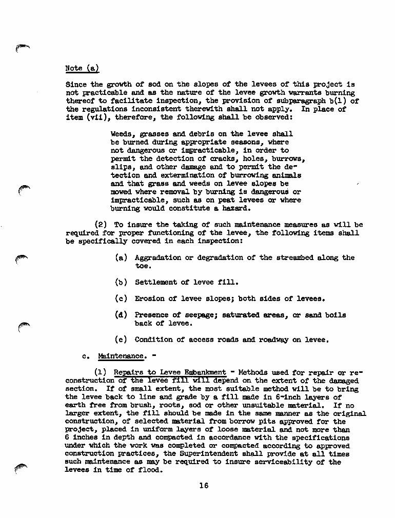
Since the growth of sod on the slopes of the levees of this project isnot practicable and as the nature of the levee growth warrants burningthereof to facilitate inspection, the provision of subparagraph b(l) ofthe regulations inconsistent therew1th shall not apply. In place ofitem (vii), therefore, the following shall be observed:
Weeds, grasses and debris on the levee shallbe burned during appropriate seasons, wherenot dangerous or impracticable, in order topermit the detection of cracks, holes, burrows,slips, and other damage and to permit the detection and extermination of burrowing animalsand that grass and weeds on levee slopes bemowed where removal by burning is dangerouS orimpracticable, such as on peat levees or whereburning would constitute a hazard.
(2) To insure the tak1ng of such maintenance measures as will berequired for proper functioning of the levee, the following items shallbe specifically covered in each inspection:
(a) Aggradation or degradation of the streambed along thetoe.
(b) Settlement of levee fill.
(c) Erosion of levee slopes; both sides of levees.
(4) Presence of seepage; saturated areas, or sand boilsback of levee.
(e) Condition of access roads and roadway on levee.
c. Maintenance.-
(1 ) Repairs to Levee Embankment - Methods used for repair or reconstruction of the ievee fill Viii depend on the extent of the damagedsection. If of small extent, the most suitable method will be to bringthe levee back to line and grade by a fill made in 6-inch layers ofearth free from brush, roots, sod or other unsuitable material. If nolarger extent, the f'ill should be made in the same manner as the originalconstruction, of' selected material from borrow pits approved f'or theproject, placed in unif'orm layers of' loose material and not more than6 inches in depth and co~cted in accordance with the specif'icationsunder which the work was completed or compacted according to approvedconstruction practices, the Superintendent shall provide at all timessuch maintenance as may be required to insure serviceability of' thelevees in time of' flood.
16

(2) Depredations of Burrowing Animal s. Dens and runwayS formedwi'th1n the levee by burrowing ani I!l8' s are frequently the causes oflevee failures during flood stages. Burrowing animals such as muskrats,ground hogs, ground squirrels, JlX)les and gophers.. found in the leveeshould be exterm1nated. The dens and runways should be opened up andthoroughly cODJ.P&cted as they are backfilled. Levees kept properlycleared are not seriously menaced by burrowing animals as they preferareas where a protective cover, such as high grass, weeds, and brushis found. Several methods of extermination are found effective, suchas trapping, baiting and poison gases, depending on the type of animalpresent and the time of year the work is done. Advice concerning thebest methods in each locality can be obtained from the County Agricultural Agent.
(3) Access Roads. Access roads to the levees shall be maintained in suCh coIidItIon that they will be accessible at all timesto trucks used to transport equipment and supplies for maintenanceof flood fighting.
(4) Levee Encroachments. (Calaveras River in the reach fromthe Southern PacifIc Railroad downstream to its JlX)uth at the SanJoaquin River.)
(a) GENERAL:
1 Certain existing encroachments have been placedunder an encroachiiient permit and approved by the State ReclamationBoard.
2 Maintenance of the encroachment and encroachmentarea will be the responsibility of the property owner.
3 Liability for daI!!8.ges due to the encroachmentswill run to the property owner •.
4 Failure on the part of the permittee to maintainthe encroachment rn an acceptable manner will result in action by' theSuperintendent to effect removal.
(b) VEGErATION:
1 Existing. Trees, shrubs and ground cover on theland8ide levee slope existing 1 November 1969 have been permitted toreDB1n, under permit, with the following exceptions: Pampas Grass,Pyracantha species, Bamboo, Berry Vines, and Cactus species.
2 New. New plantings will be considered on anindividual basis when permit application is made. All new plantings will conform to criteria in the "Levee Encroachment-Quide forFencing and Vegetation on Project Levees, Mormon Slough Unit No.3".
17
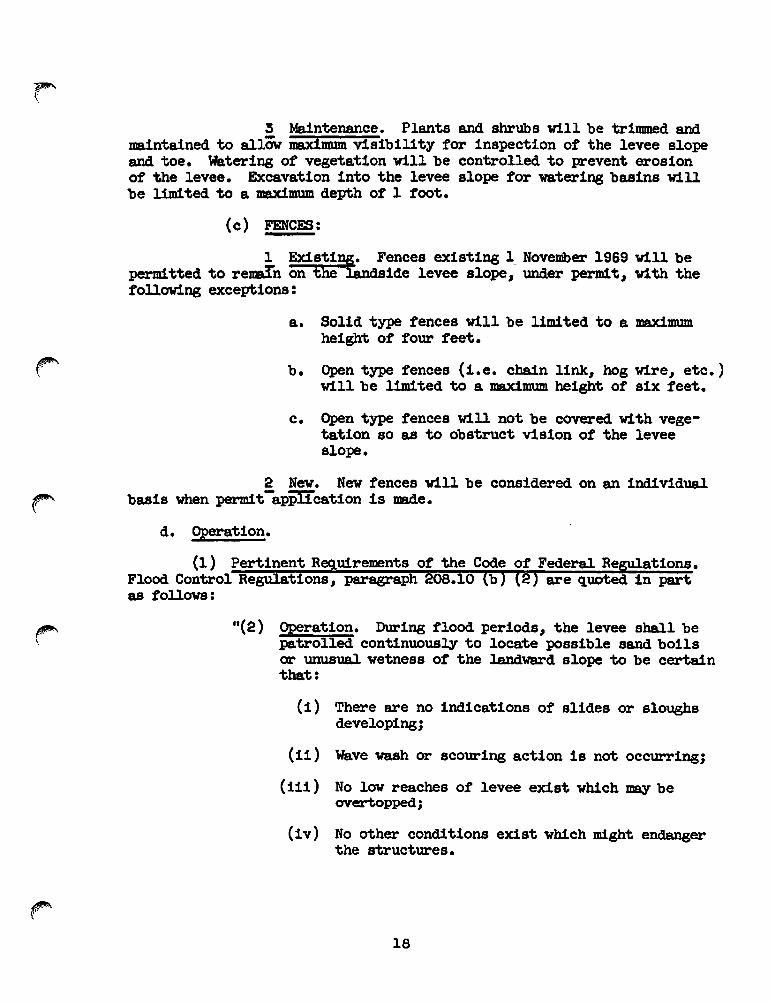
3 Maintenance. Plants and shrubs will be trimmed andmaintained to allOW Di8Jdmum visibility for inspection of the levee slopeand toe. Watering of vegetation will be controlled to prevent erosionof the levee. Excavation into the levee slope for watering basins willbe l1m1ted. to a maximum depth of 1 foot.
(c) FENCES:
1 Existing. Fences existing l November 1969 vill beperm!tted to remI'n on the landside levee slope, under perm1t, with thefollowing exceptions:
a. Solid type fences will be limited to a maximumheight of four feet.
b. Open type fences (i.e. chain link, hog wire, etc.)will be limited to a maximum height of six feet.
c. Open type fences vill not be covered. with vege"tation so as to obstruct vision of the leveeslope.
2 New. New fences will be considered on an ind1vidualbasis when perm1t-apP'ITcation is made.
d. Operation.
(1) Pertinent Requirements of the Code of Federal Re ations.Flood Control Re :tions, paragraph 08.10 b are quoted in partas follows:
"(2) Operation. During flood periods, the levee shall bepatrolled. continuously to locate possible sand boilsor unusual wetness of the land'WBrd slope to be certainthat:
(i) There are no indications of slides or sloughsdeveloping;
(ii) Wave wash or scouring action is not occurring;
(11i ) No low reaches of levee exist which may beovertopped;
(iv) No other conditions exist which m1ght endangerthe structures.
18

Appropriate advance meaS'lU"es will be taken to insm-e theavailabillty of adequate labor and materials to meet allcontingencies. Immediate steps will be taken to controlany condition which endangers the levee and to repa:1rthe damaged section. II
(2) It shall be the duty of the Superintendent to keep incontact with the State Department of Water Resources' Flood OperationCenter d'lU"ing all Periods of flood danger as necessary to take advantage of its forecasts and maintain a patrol of the project works intheir area d'lU"ing Periods of flood in excess of reading of 12.0 on thegage located on the lett bank of Mormon Slough about 1400 feet ~stream from Escalon-Bellota Road as referred to in paragraph 1-06 ofthis manual.
The Flood Operations Center is responsible for data collectionand issuance of a joint stream forecast with the U. S. weather B'lU"eauand coordinates with the Sacramento District Engineer and other agencies to keep appraised of the cm-rent situation in accordance withterms of the Memorandum of Understanding dated 1 NOVember 1956, between the Division Engineer, U. S. Arrrry Engineer Division, SouthPacific, and the Director, Department of Water Reso'lU"ces, State ofCalifornia, for cooperative action during flood emergencies.
4-03. Channels and Floodways.
a. Description. The channel of this project extends: along theCalaveras River from the San Joaquin River upstream to McAllen Road;along the Diverting Canal from the Calaveras River ~stream to MormonSlough; along Mormon Slough from the Diverting Canal upstream to Belleta; and along Potter Creek from Mormon Slough upstream to Jack ToneRoad, a total distance of about 25.7 miles. The channel improvementsconsisted Jmstly of clearing between the levees or banks and channelenlargement from degrading and borroving operations. Regulations regarding inspection, maintenance, and operation of channels and floodways will be found in paragraph 4-o3b, c and d of this manual.
b. Inspection.
:tiona.are quoted in part
lI(g) Channels and floodways ••• (1) Maintenance.Periodic inspections ••• shall be DIlde by the Superintendent to be certain that:
(i) The channel or floodWB¥ is clear of debris, weeds,and wild growth;
19
~I

(ii) The channel or f'loodway is not being restricted bythe depositing of' waste materials, building of' unauthorized structures or other encroachments;
(iii) The capacity of the channel or f'lood'W8Y is not beingreduced by the f'ormation of' shoals;
(iv) Banks are not being damaged by rain or wave wash,and that no sloughing of banks has occurred j
(v) Riprap sections and deflection dikes and \I8.lls arein good condition;
(vi) Approach and egroess channels adjacent to the improved channel or f'loodway are sufficiently clearof obstructions and debris to permit proPer :functioning of the project works.
Such inspections shall be made by the Superintendent priorto the beginning of the flood season and otherwise at intervals not to exceed 90 days. Immediate steps will betaken to remedy any adverse conditions disclosed by suchinspections • • ."
(2) The Purpose of the flood-flow channels inspection is toinsure that conditions which affect the channel capacity will remainthe same, as far as possible, as those considered in the design assumptions and that no new conditiona develop that may effect the stabilltyof the project structures. At each inspection required byparagraph 208.10(g)(l) of the Flood Control Regulations, particularattention will, therefore, be given the following:
(a) location, extent and size of vegetal growth.
(b) Unauthorized operations within the flood-flow channelright-of-way, such as excavations, buildings and otherstructures, levees" bank protection, or training dikes.
(c) Rubbish and industrial waste disposal.
(d) Changes in the channel bed such as aggradation or degradation, which would interfere with :tree-tlow :tromside drainage structures or induce local meanders thatwould scour the banks.
( e ) Operations of any nature upstream :trom the project thatwould affect flow conditions within the lim!ts of theflood control project.
20

(f) Condition of project structure.
1. Channel walls:
~. Deviation from alignment and grade.
Eo. Development of cracks and spalls.
,=,. Mechanical injuries.
2. Fencing:
a. Injuries to post, fencing or barbed wire.
:2,. Damage to galvan1zing.
3. Earth fills:
a. Settlement.-~. Erosion of both slopes.
,=,. Excessive seepage or saturation area back of~~. ~
d. Condition of bank protection - concrete orstone blanket.
4. Right-of-way:-a. Presence of dumped refuse.
~. Encroachment or trespass.
(3) No excavation within the limits of this unit of the MormonSlough Project will be permitted unless an excavation permit has beenapproved by the State Reclamation Board and the District Engineer.
(4) If any work is done to improve flow conditions in MormonSlough Project an excavation permit must be obtained from the Superintendent and approved by the District Engineer.
(5) The intent of these inspections is to disclose all conditions which in any way affect the stabillty of the structures and theirf'unctioning for the control of floods. Each inspection report shouldnote and comment on any repair measures that have been taken since thelast inspection. In mak1ng these inspections I the check sheets includedas EXHIBrr E shall be expllcitly followed.
2l

c. Maintenance.
of Federal Re tions.are quoted in part
" • • • Immediate steps will be taken to remedy any adverse conditions disclosed by such inspection ••• "
(2) Shoaling or aggradation at the inlets or outlets of sidedrainage structures may render them inoPerative. It is" therefore"imperative that all drains be kept open and unobstructed at all times.
(3) 'Dumped rock or other suitable types of protection should beplaced at locations found by experience to be critical trouble' points"with a view to stabilizing the channel alignment and preserving thegeneral uniform1ty of the bank lines.
(4) Sediment and debris plugs or other obstructions should beremoved from the channel to prevent any tendency for the flows to be deflected within the channel. The heavy material likely to accumulate inthe new channel at the mouths of tributaries should be reJOOved to keepthe channel clear.
(5) The channel and right-of-way shall be kept reasonably clearof debris" refuse matter" or industrial wastes in accordance with criteria of the California State Water Control Boards.
( 6 ) weeds and other vegetal growth in the channel shall be cutin advance of flood season and together with all debris" removed fromthe channel.
('" ( 7 ) All eroded concrete shall be rePaired as soon as any re-inforcing steel is exposed or erosion approaches a depth of 4 inches.For this purpose" it is recommended that the repair be made by thoroughlyclearing the surface by sandblasting and building up the section withpneumatically placed Portland cement mortar. All eVidence of settlement"uplift" or failure of concrete structures shall be referred to the stateDePartment of Water Resources for analysis and remedial measures.
(8) All damage to fencing" whether resulting from accidental orwillful injuries or from corrosion" shall be promptly rePaired with newmaterial in order to maintain satisfactory protection to the public.
~. Operation.
(1 ) Pertinent R uirements of the Code of Federal ReParagraph 208. g are quoted in Part as follows:
22
tions"

Il(g) Channels and floodways ••• (2) Operation. Bothbanks of the channel shall be patrolled during periods ofhigh water • • • Appropriate measures shall be taken toprevent the formation of jams ••• ot debris. large objects which become lodged against the bank shall be removed.The improved channel or floodway shall be thoroughly inspected 1mmed1ately following each major high water period.As soon as practiCable thereafter all snags and other debrisshall be removed and all damage to ••• wallS, drainageoutlets or other flood control structures repaired. II
e. Special Instructions.
(1 ) Revetment Work. Due to the fact that many reaches of con-tiguous bank h&ve been constructed with stone protection work consisting "'"of quarry stone or cObbles" the provisions of paragraphs 4-o3b(1)(v) and'4-o3b(2)(f)3.d. are expanded to include the following:--
(a) Where scour, wash, settlement or failure of a Portionof the originally provided stone protection has beennoted" or where inspection indicates th8.t such damagemay result during the next flood or high water period,the scour or wash shall be filled with earth tree fromb~h, roots, sodoro~er~smtablematerialandm
d1tional stone shall be placed upon the earth fill tobring the stone protection to its original section.In case of emergency and when stone is not available,sand bags or bags filled with gravel may be used fortemporary rePair measures.
(b) When permanent rePair of the stone protection is made,the stone used shall" as far as possible, be similar ~
to the kind and gradation as originally used, and shallbe placed to the thickness as shown on ~e drawings ofExhibit B.
(c) In the event an inspection reveals that due to scour,settlement or other causes, stone protection on thelevee Or bank is reqmred beyond the 11mits of the original construction or in reaches of the levee or banknot originally provided w1:th such protection, local interests will provide mditiona! sloping of the bank andplacement of stone protection as needed to protect completed work. The work shall be done in a manner acceptable under standard engineering practice.
(d) Trees and brush should not be allowed to grow throughthe stone blanket to the extent that it displaces thestone or causes increase in velocities against the
23
4-03e.
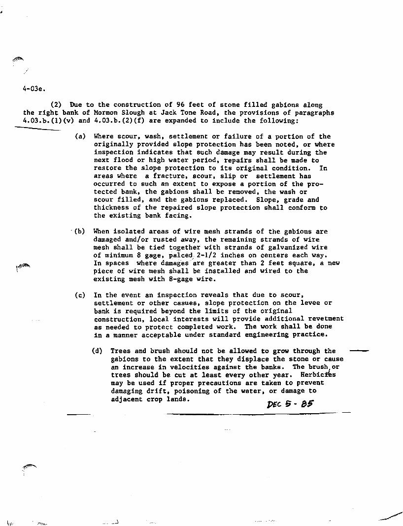
(2) Due to the construction of 96 feet of stone filled gabions alongthe right bank of Mormon Slough at Jack Tone Road, the provisions of paragraphs4.03.b.(I)(v) and 4.03.b.(2)(f) are expanded to include the following:
(a) Where scour, wash, settlement or failure of a portion of theoriginally provided slope protection has been noted, or whereinspection indicates that such damage may result during thenext flood or high water period, repairs shall be made torestore the slope protection to its original condition. Inareas where a fracture, scour, slip or settlement hasoccurred to such an extent to expose a portion of the protected bank, the gabions shall be removed, the wash orscour filled, and the gabions replaced. Slope, grade andthickness of the repaired slope protection shall conform tothe existing bank facing •
. (b) When isolated areas of wire mesh strands of the gabions aredamaged and/or rusted away. the remaining strands of wiremesh shall be tied together with strands of galvanized wireof minimum a gage, palce~. 2-1/2 inches on centers each way.In spaces where damages are greater than 2 feet square, a newpiece of wire mesh shall be installed and wired to theexisting mesh with a-gage wire.
(c) In the event an inspection reveals that due to scour,settlement or other casues. slope protection on the levee orbank is required beyond the limits of the originalconstruction. local interests will provide additional revetmentas needed to protect completed work. The work shall be donein a manner acceptable under standard engineering practice.
(d) Trees and brush should not be allowed to grow through thegabions to the extent that they displace the stone or causean increase in velocities against the banks. The brus~Jor
trees should be cut at least every other year. Herbic%esmay be used if proper precautions are taken to preventdamaging drift, poisoning of the water, or damage toadjacent crop lands.

bank. The brush or trees should be cut at least everyother year. Herbicides may be used if proper precautions are taken to prevent damaging drift, poisoningof the water or damage to adjacent crop lands.
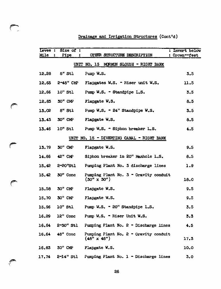
4-04. Drainage and Irrigation Structures.
a. Description. Drainage and irrigation structures which extendthrough the levee are listed as follows:
levee Size of Invert belowMile Pipe 01'HER STRUCTURE DESCRIPl'ION . Crown--feet•
UNIT NO. 15 MORK>N SLOOGH - RIGHI' BANKr
Ca)1.18 18" CMF Drain Inlet - Ungated 7.0
1.49 18" CMF Drain Inlet - Ungated Ca) 6.0
1.52 12" St.l 2-inch breather WS - Pump L.S. 11.0
2.10 14" Stl Valve W.S. • Pump L.S. 9.5
2.64 8" Stl Abandoned 1.0
3.64 10" Stl Pump W.S. - 24 II St.andpipe L.S. 4.5
3.88 lO" Stl Pump W.S. • 2411 St.andpipe L.S. 5.0
3.98 8" Stl Pump W.S. • 30 11 Standpipe L.S. 4.0
4.75 12" St.l Pump W.S. - 30" St.andpipe L.S. 14.3
5.28 14" Conc 2411 Standpipe W.S. 7.5
5.46 14" Conc 8 11 St.andpipe W.S. :5.5
5.58 18" CMF Drain Inlet - Ungated Ca) 3.5
6.54 16" Conc Siphon across channel 4.0
6.75 12" Cone 24" Standpipe W.S. - Pump W.S. 5.0
7.15 8" Stl Abandoned :5.0
7.15 12" Conc 36" Standpipe L.S. 1.5
7.38 10" Cone Pump W.S. - 30" Standpipe W.S. 4.0
24


~.,-
Drainage and Irrigation Structures (Cont'd)
Levee Size of : Invert belowMile . Pipe arHER STRUCTURE DESCRIPl'ION Crown--feet.
UNIT NO. 15 - CAlAVERAS RIVER - RIGHT BANK
24.14 8 11 Cone Severl1ne - Siphon breaker W.S. 3.1
24.14 1211 Cone Sewerl1ne - Siphon breaker W.S. 4.0
24.24 1411 St1 Pump W.S. - Standpipe W.S. 12.0
24.24 1011 St1 Pump W.S. - Standpipe 'W.S. 12.0
25.05 12" St1 Pump W.S. - Riser Unit L.S. 5.3
25.26 4 11 Stl Pump W.S. 2.0
25.38 1211 stl Riser Unit W.S. - Standpipe L.S. 5.0
UNIT NO. 16 - l«>RMOO SLWGH - IEF1' BANK
r 0.27 12" Cone Pump L.S. • Standpipe L.S. 14.0
0.44 14" Cone Pump W.S. - Standpipe W.S. 3.5
0.82 18" CMP Drain Inlet - Ungated (a) 4.5
0.96 2-12 11 Cone Pump W.S. - 36 11 Standpipe W.S. 12.0
" 1.16 12" Cone Pump W.S. • 3011 Standpipe W.S. 4.0(
1.52 1411 Cone Pump W.S. • 3011 Standpipe W.S. 3.3
1.69 1211 Cone Pump W.S. • 3011 Standpipe W.S. 3.0
1.95 12" Cone Pump W.S. - Distribution box W.S. 3.0
2.47 12" Cone Pump W.S. - 3011 Standpipe L.S. 3.0
2.52 18" CMP Drain Inlet - Ungated (a) 3.5
2.82 36" CMP Ungated (a) 10.0
3.53 1211 Cone PUllW W.S. • 30" Standpipe W.S. 4.3
3.53 2411 Cone Pump W.S. - 30" Standpipe W.S. 6.9
,f""/
28


Drainage and Irrigation Structures (Cont I d)
~1I
LeveeMile
Size ofPipe DrHER STRUCTURE DESCRIPrION
: Invert belowCrOlm--feet
UNIT NO. 16 - DIVERTING CANAL - lEFT BANK
16.53 24" Stl
16.69 6" & 24"Stl
16.91 24" Stl
Flapgate W.S. - Riser unit W.S.
F1apgate W.S. - Manhole L.S.
Pump L.S. - Flapgate W.S.
4.5
8.0
8.5
17.79 18"&24"St1 Flapgates W.S. - Riser units L.S.
UNIT NO. 16 - CALAVERAS RIVER - I.EFr BANK
18.98 16" & 20"Stl Pump L.S. - Flapgate W.S.
19.68 1-20" St1& 2-16 11 Stl Pump L.S. - Flapgate W.S.
4.5
5.8
20.27 3" Stl
20.53 12" Stl
20.92 10" St1
21.36 4" Stl
21.54 12" Conc
21.55 8" Stl
22.21 6" Conc
22.27 g" Stl
22.37 7" Stl
22.47 10'1 Stl
22.88 1811 Stl
23.36 18" Stl
23.36 2011 Stl
Ungated (a)
Waterma1n
Pump L.S. - Gate valve L.S.
Pump W.S.
Siphon under channel - Riser unit W.S.
Capped L.S.
Pump W.S.
Pump W.S.
(Abandoned)
Pump L.S. - Riser unit W.S.
Pump L.S. - Siphon breaker W.S.
Pump L.S. - Siphon breakers W.S.
Pump L.S. - Siphon breakers W.S.
8.0
1.0
5.0
5.1

Drainage and Irrigation Structures (Cont’d)
Levee Mile Size of Pipe
Other Structure Description Invert Below Crown Feet
UNIT NO. 17 – POTTER CREEK – RIGHT BANK 0.33 16” Conc Siphon under channel – 30” Standpipe
L.S. 4.0
0.59 14” Conc Siphon under channel 3.0 0.60 18” CMP Drain Inlet – Ungated (a) 3.8
UNIT NO. 18 – POTTER CREEK – LEFT BANK 0.00 30” CMP Flapgate W.S. 6.0 0.28 30” CMP Flapgate W.S. 6.0 0.29 14” Conc Siphon under channel – Riser unit L.S. 3.3 0.54 30” CMP Flapgate W.S. 6.0 0.55 16” Conc Siphon under channel 5.0
Note on abbreviations: W.S. = Waterside L.S. = Landside
(a) = Landside adjacent ground elevation above Project Design Flood Plane
Added February 1999: Description. Drainage and irrigation structure construction, extension or replacement has been completed according to As Constructed Drawings. Levee mile and station references are relative to the As Constructed Drawings. Newly constructed, extended, or protected drainage structures are listed in the following table. Segments identified in the following table are defined in the Vicinity Map (see EXHIBIT APPENDIX-1). Segment: Upper Calaveras Approximate
Station Corresponding
Levee Mile Bank Pipe
Diameter (inches)
Remarks
310 + 46 5.88 L Double 6’x 6’ Box
New return structure constructed
310 + 80 5.89 L 56 Protected in Place 318 + 30 6.03 L 30 Extended 15-feet 345 + 65 6.55 R 30 New Culvert constructed 351 + 10 6.65 L 30 New Culvert constructed 393 + 00 7.44 L Protected in place 395 + 00 7.48 L 30 New culvert constructed 404 + 10 7.65 R 12 Protected in Place 418 + 40 7.92 L 12 Removed existing 419 + 50 7.95 R Removed existing 420 + 45 7.96 R 30 New culvert constructed 433 + 00 8.20 L 18 Removed existing
32

434 + 65 8.23 L 30 New culvert constructed 449 + 00 8.50 R Extended 10-feet
Segment: Stockton Diverting Canal
93 + 85 1.78 R 30 Protected in place 154 + 20 2.92 R 30 Protected in place
Segment: Mormon Slough
0 + 79 0.01 R 36 Protected in place 17 + 28 0.33 R 15 Protected in place 47 + 50 0.90 L 32 Protected in place 48 + 45 0.92 R 32 Protected in place 57 + 68 1.09 R 2 x 48 Protected in place 66 + 15 1.25 L 30 Protected in place 84 + 10 1.59 L 30 Protected in place 109 + 60 2.08 R 18 Protected in place 125 + 00 2.37 L 30 Protected in place
Section: Potter Creek
145 + 26 2.75 L 30 Protected in place 150 + 50 2.85 L 30 Protected in place 173 + 30 3.28 L 30 Protected in place
For specific locations and detailed descriptions of drainage and irrigation structures please see As Constructed Drawings which are on file with the San Joaquin Area Flood Control Agency. b. Inspection. (1) Pertinent Requirements of the code of Federal Regulation. Flood Control Regulations, paragraph 208.10(d) (1), are quoted in part as follows: “(d) Drainage Structures (1) Maintenance – Adequate measures
shall be taken to insure that inlet and outlet channels are kept open and that trash, drift, or debris is not allowed to accumulate near drainage structures.
Flap gates and manually operated gates and valves on drainage
structures shall be examined, oiled and trial operated at least once every 90 days . . . Periodic inspections shall be made by the Superintendent to be certain that:
(i) Pipes, gates, operating mechanism, riprap and
headwalls are in good condition;
32a

(11) Inlet and outlet channels are openj
(i11) Care is being exercised to prevent the accumulation of trash and debris near the structuresand that no fires are being built near bitum!nous coated pipesj
(iv) Erosion is not occurring adjacent to the structure which m:l.ght endanger its water tightnessor stability. Immediate steps will be taken torepair damage, replace m:l.ssing or broken parts,or remedy adverse conditions disclosed by suchinspections."
(2) At each inspection the following items, if applicable,shall be particularly noted:
(a) Debris or other obstructions to flow.
(b) Condition of pipes and gates.
( c ) Damage or settlement of pipe.
(d) Condition of concrete-cracks .. spalla, erosion.
c. Maintenance.
(1) All eroded concrete shall be repaired as soon as erosionreaches a depth of 4 inches or any reinforcing steel is exposed. Forthis purpose it is recommended that the repair be made by thoroughlycleaning the surface by sandblasting and building up the concrete toits original section with pneumatically-placed Portland cement mortar.All evidence of settlement, uplift, or failure of concrete structuresshould be referred to the State Department of Water Resources for analysis and recommendation of remedial measures.
(2) If the inspection shows that the automatic drainage structures have been jammed in an open position by debris or other obstruc"tions, they shall be thoroughly cleaned so that they swing freely to atrue closure. If any parts of the gates have been c1amaged or broken,they shall be replaced by new parts.
( 3 ) Compliance with the provisions prescribed above pertainingto drainage structures is essential for proper maintenance of the leveesystem covered by this manual. U!vee failures caused by neglected drainage structures are of cODDllOn occurrence j it is.. therefore, of utmost importance that these structures always be kept in perfect working condition in accordance with the regulations.
33
""""I
~, -'

(4) Care should be taken not to bury any of the side drainageinlets in the event that it becomes necessary to fill any of the low·lying pockets in back of the levee. Plans for the maintenance of drain"age faci11ties at any such points should be subml.tted to the State Rec1all:B.tion Board for approval before such work is started.
d. Operation.
n(2) Operation. Whenever high water conditions impend..all gates will be inspected a short time before waterreached the invert of the pipe and objects which mightprevent closl.U"e of the gate shall be removed. Automaticgates shall be closely observed until it has been ascertained that they are securely closed • • • All drainagestructl.U"es in the levee shall be inspected frequentlyduring floods to ascertain whether seepage is taking placealong the 11nes of their contract with the embankment.Immediate steps shall be taken to correct any adverseconditions. "
(2) The outlets of the side drainage structures inundate atrelatively low river stages. They should.. therefore .. be inspected atthe first sign of a rise in the river to make certain that the gatesare not jammed in an open position and thus allow flood waters to enterbehind the levee.
4-05. Miscellaneous Faci11ties.
a. Description. Miscellaneous structures or facilities which wereconstructed as a part of, or existed in conjunction with, the protectiveworks, and which might affect their :f'unctioning, include the following:
(1) Bridges.
Levee Mile - left Bank
0.15
2.80
4.06
•• Stream
Unit No. 16
Mormon Slough
Mormon Slough
Mormn Slough
•. Name of Road
Escalon - Bellota Road
Fine Road.
Flood Road.

Ievee Mile - L;f'£ Bank • Stream Name of Road•
Unit No. 16
6.48 Mormon Slough Milton Road
7.09 Mormn Slough Duncan Road
7.34 Marmn Slough SF Railroad
8.32 MorJOOn Slough Copperopolis Road
10.51 Mormn Slough Jack Tone Road
11.58 Mormon Slough Farm Bridge (Panella)
13.87 Diverting Canal East Main Street
15.04 Diverting Canal SP Railroad
15.59 Diverting Canal Linden Road
16.38 Diverting Canal S.T. & E. Railroad ~
16.71 Diverting Canal US Highway 99 (2)
16.89 Diverting Canal Waterloo Road
17.26 Diverting Canal Cherokee Road
17.61 Diverting Canal C.C.T. Railroad
17.83 Diverting Canal Wilson Way
18.31 Diverting Canal Sanguinetti lane
18.67 Calaveras River SP Railroad
18.99 Calaveras River West lane (2)
19.22 Calaveras River W.P. Railroad
19.93 Calaveras River El Dorado Avenue
20.54 Calaveras River Pacific Avenue
20.84 Calaveras River Pedestrian Bridge
21.16 Calaveras River Pershing Avenue ~,
35

~\' .. ..,
Levee Mile - felt Bank
22.48
22.50
0.00
0.29
0.56
Stream
Unit No. 16
Calaveras River
Calaveras River
Unit No. 18
Potter Creek
Potter Creek
Potter Creek
•• Name of Road
Interstate 5 (North)
Interstate 5 (South)
Jack Tone Road
Farm Bridge (Magnacco)
Farm Bridge (Iavaggi)
(2) Utility Relocations. Because of the nature of the construction of the utilities by ioC8i interests, records of utility relocationsare not available.
(3) Hydrologic Facilities. A continuous water stage recorder~ and staff gage located on the left bank of MorJoon Slough about 1400 feett . upstream from Escalon-Bellota Road. Another continuous water stage re
corder with associated staff gages is located on the right bank of theDiverting Canal about 200 feet downstream from Cherokee lane. Thesestations to be operated and. maintained by the State of California Department of Water Resources, in cooperation with the San Joaquin CountyFlood Control and Water Conservation District.
(4) Low Water Crossings. Low water crossings are listed asfollows:
ulilt
15
15
15
•• Levee Mile - Right Bank
4.91
8.79
11.10
36
•. Stream
Marmon Slough
Mormon Slough
Mormon Slough
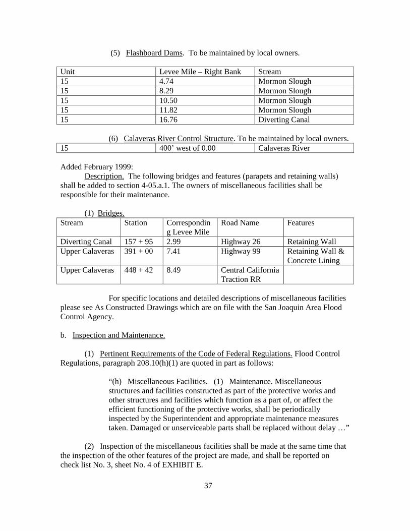
(5) Flashboard Dams. To be maintained by local owners. Unit Levee Mile – Right Bank Stream 15 4.74 Mormon Slough 15 8.29 Mormon Slough 15 10.50 Mormon Slough 15 11.82 Mormon Slough 15 16.76 Diverting Canal
(6) Calaveras River Control Structure. To be maintained by local owners. 15 400’ west of 0.00 Calaveras River Added February 1999: Description. The following bridges and features (parapets and retaining walls) shall be added to section 4-05.a.1. The owners of miscellaneous facilities shall be responsible for their maintenance.
(1) Bridges. Stream Station Correspondin
g Levee Mile Road Name Features
Diverting Canal 157 + 95 2.99 Highway 26 Retaining Wall Upper Calaveras 391 + 00 7.41 Highway 99 Retaining Wall &
Concrete Lining Upper Calaveras 448 + 42 8.49 Central California
Traction RR
For specific locations and detailed descriptions of miscellaneous facilities please see As Constructed Drawings which are on file with the San Joaquin Area Flood Control Agency. b. Inspection and Maintenance. (1) Pertinent Requirements of the Code of Federal Regulations. Flood Control Regulations, paragraph 208.10(h)(1) are quoted in part as follows: “(h) Miscellaneous Facilities. (1) Maintenance. Miscellaneous
structures and facilities constructed as part of the protective works and other structures and facilities which function as a part of, or affect the efficient functioning of the protective works, shall be periodically inspected by the Superintendent and appropriate maintenance measures taken. Damaged or unserviceable parts shall be replaced without delay …”
(2) Inspection of the miscellaneous facilities shall be made at the same time that the inspection of the other features of the project are made, and shall be reported on check list No. 3, sheet No. 4 of EXHIBIT E.
37

(3) The interest of the Corps of Engineers and the responsibility of the local interests in the existing highway and railroad bridges is confined to their effect on the safety and functioning of the flood control channel, but any conditions noted in the inspections that may affect them in any way should, as a matter of courtesy, be brought to the attention of the agencies maintaining and operating them. If the inspection of any miscellaneous structure, either existent or constructed in the future under permit, discloses any condition that indicates the probability
37a
../
_~rt .I~.<--<!£.,(/ .
of failure during periods of high 'Water I the Superintendent shall addressa letter to the owner of the structure I quoting this manual as authorityand inviting attention to the conditions observed and requesting that immediate steps be taken to correct them. A copy of such letter shall beforwarded to the District Engineer for his information. A report on theaction taken by the owner shall be sUbmitted to the District Engineer toaccompany the next semi-annual report. A suggested report form is ineluded as EXHIBIT D of this manual.
(4) The purpose of maintenance work is to insure continuous satisfactory operation of equipment. It is I therefore I important in suchwork that all possible causes of future troUble be found and corrected.Particular attention should be given to minor weaknesses which may be anindication of future troUble.
c. Operation.
"(2) Operation. Miscellaneous facilities shall be operated to prevent or reduce flooding during periods of high'Water. Those facillties constructed as a part of the protective works shall not be used for purposes other thanflood protection without approval of the District Engineerunless designed therefore. II
(2) The flashboard dams listed under paragraph 4-05a. (5) shallbe operated to prevent bank caving and sloughing by reason of rapid drawdown. All required flashboards may be placed in the dams during theperiod from 15 April to 15 OC"tober. All flashboards shall normally beout during the 15 October to 15 April flood period. ,Howeverj- fluhboard,Dl8\V' be tf#~ily 1mlta1~ed dur1!lg.~s flood period-1ipc)n rece:tPtat i L
'spec1f1cwrlt'teI! -~pprova1 tram ~~1nte~~.Th1s apprcmu. wiUmclude instructions far prompt remov8J. at these flashboardS whenever,;floods are 1mm1nen1i.
j,
(3) It is estimated that the Calaveras River Control Structurelisted under paragraph 4-05a. (6) will pass approximately 600 c.f.s.during a project design flow of 12, 500 c. f. s. in the Calaveras River atBe1lota. This is less than the estimated non-d.a:maging flow capaci1iy of1ihe Calaveras River below the dam. The Mormon Slough channel has beendesigned and constructed to pass the design f~ow of 12, 500 c.f.s. AccordinglyI local interests if they so desire I can co~1etely shut offfloodfloWB from the Calaveras River by closure of the gates in theirdam. To prevent tloodfloWB in the Calaveras River the gates shouldbe closed in the period from 1 November to 15 Apr1~ of each year.
38
4-06. Floodwalls.
a. Description. Floodwalls have been built where raising the levee using fill was not possible. The floodwalls were constructed near the hinge point of the land or water side of the existing levee. For specific locations and detailed descriptions of water side of floodwalls please see As Constructed Drawings which are on file with the San Joaquin Area Flood Control Agency. Regulations regarding inspection, maintenance and operation are included in paragraphs 4-06.b., 4-06.c., and 4-06.d. of this addendum.
b. Inspection.
(1) Pertinent Requirements of the Code of Federal Regulations. Flood Control Regulations, paragraph 208.10(c)(1), are quoted in part as follows: “(c) Flood walls – (1) Maintenance. Periodic inspections shall be made by the Superintendent to be certain that:
(i) No seepage, saturated areas, or sand boils are occurring;
(ii) No undue settlement has occurred which affects the
stability of the wall or its water tightness; (iii) No trees exist, the roots of which might extend
under the wall and offer accelerated seepage paths;
(iv) The concrete has not undergone cracking, chipping, or breaking to an extent which might affect the stability of the wall or its water tightness;
(v) There are no encroachments upon the right-of-way
which might endanger the structure or hinder its functioning in time of flood;
(vi) Care is being exercised to prevent accumulation of
trash and debris adjacent to walls, and to insure that no fires are being built near them;
(vii) No bank caving conditions exist riverward of the
wall which might endanger its stability;
(viii) The drainage systems and pressure relief wells are in good working condition, and that such facilities are not becoming clogged.
38a
Such inspections shall be made immediately prior to the beginning of the flood season, immediately following each major high water period, and otherwise at intervals not exceeding 90 days. Measures to eliminate encroachments and effect repairs found necessary by such inspections shall be undertaken immediately….”
(1) During periodic inspections specified in section 4-06.b.1
notice shall also be taken of graffiti and other improper markings hindering the aesthetic value of floodwalls. All graffiti abatement repairs shall be accomplished by methods acceptable in standard engineering practice.
c. Maintenance. (1) Pertinent Requirements of the Code of Federal Regulations.
Flood Control Regulations, paragraph 208.10(c)(1), are quoted in part as follows:
“All repairs shall be accomplished by methods acceptable
in standard engineering practice.”
c. Operation.
(1) Pertinent Requirements of the Code of Federal Regulations. Flood Control Regulations, paragraph 208.10(c)(2), are quoted in part as follows:
“(2) Operation. Continuous patrol of the wall shall be maintained during flood periods to locate possible leakages at monolith joints or seepage underneath the wall. Floating plant or boats will not be allowed to lie against or to tie up to the wall. Should it become necessary during a flood emergency to pass anchor cables over the wall, adequate measures shall be taken to protect the concrete and construction joints. Immediate steps shall be taken to correct any condition which endangers the stability of the wall.”
38b
SECTION V
SUGGESTED METHODS OF COMBATING FLOOD CONDITIONS
This section shall be amended to include floodwalls in addition to earthen levees.
5-01. Methods Suggested. Most of the methods described herein have been developed during years of experience with the various problems that often come up during periods of high water, and they are not intended to restrict the Superintendent, or others concerned, to a rigid set of rules for every condition that may arise. The remarks are primarily concerned with the earthen portions of the levee system. If problems not covered by these suggestions arise, where the Superintendent is in doubt as to the procedure to be taken, he will be expected to consult the State Department of Water Resources, and follow standard engineering practices in meeting the situation. It should be noted that it is much better to be over-prepared for a “flood-fight” than to find at the last moment that preparations were incomplete or unsatisfactory. Confidence of the protected persons and firms is a valuable asset that should not be carelessly lost through inefficient operation of the protection system in time of emergency.
5-02. Earthen Levees. An earthen levee is in danger whenever there is water against it.
This danger is directly proportional to the height of the water, the duration of the flood stage, and the intensity of either the current or wave action. The danger is inversely proportional to the cross-sectional area of the levee, the levee’s height, and the degree of maintenance. A well constructed levee of proper section should, if maintained and not overtopped, hold through any major flood. However, a serious accident may result in a break. Foundation troubles result in sand boils or a sinking levee, and the local use of unsatisfactory materials causes slides and sloughs. However, such threatened failures can be met if prompt action is taken and proper methods of treatment are used. Wave wash is to be expected whenever the levee is exposed to a wide stretch of open water and is serious if permitted to continue over a considerable length of time. Floodwalls. A floodwall is in danger whenever there is water against it. This danger is directly proportional to the height of the water, the duration of the flood stage, and the intensity of either the current or wave action. A well constructed floodwall with proper foundation should, if maintained and not overtopped, hold through any major flood. Seepage under the floodwall or leakage through joints may result in failure.
5-03. Premeditated Damage. Local interests should continually guard against
premeditated damage to the levee. In the event of an extraordinary flood requiring a fight over long stretches of levee on both sides of the river, there is a natural temptation to relieve the strain by premeditated breaking of the opposite levee.
39

5-04. Security. Personnel of the Corps of Engineers, whether military or civilian, are not vested with any civil police authority in the performance of their engineering duties, and they will not attempt to exercise any such authority. The responsibility for protecting flood control works against sabotage, acts of depredation or other unlawful acts rests with the local interests through local and State Governmental agencies.
39a
5-05. Inspection of Flood Control Works. Immediately upon receipt ofinformation that high water is imminent, local interests responsible formaintenance should form a skeleton organization, capable of quick expansion, and assign individuals (sector Foremen) to have charge of definit~
sections of levees. As his initial activity, each sector Foreman shouldgo over his entire sector and Parts of adjacent sectors, making a detailedinspection, Particularly with reference to the following matters:
a. sector limits; ascertain that the dividing line between sectorsis plainly determined and, if necessary, marked.
b. Condition of new levees and recent rePairs.
c. Condition of culverts, flap gates, and sluice gates.
d. Transportation facilities; roads, rail and water communications.
e. Material supply; quantity, location, and condition.
f. Communications; locate and check all necessary telephones in thesector.
5-06. Preliminary Repair Work. After the initial inspection has beenmade, each sector Foreman should recruit a labor crew and proVide it withtools such as shovels, axes, wheelbarrows, etc. In addition, bulldozers,scrapers, trucks, etc. should be located and made ready for use in caseof emergency. Then immediate action should be taken to perform the following work:
a. Fill up holes or washes in the levee crown, slopes, and landsideberms. Where new construction has been completed during the year, rainwashes and deep gullies may have developed. While the levee is new, preparations should be made to advance to combat wave wash along the exposedreaches.
b. RePair gaps where road crossings have been worn down and the leveeis below grade. In filling the road crossings, it may be necessary toobtain material from landside borrow pits, in which case excavation forthe material should be kept at least 50 feet from the toe of the levee./my filling done in this connection should be tamped in place and, if inan exposed reach.. subject to wave wash, the new section should be facedwith bags of sand.
c. RePair and close all flap gates on culverts and see that they areseated properly before they are covered with flood waters.
40
d. Ascertain that all roads to and along the levee are in a good state of repair. The Superintendent should obtain assistance from the county road forces to have all roads put in first-class condition. e. Locate necessary tools and materials (sacks, sandbags, brush, lumber, lights, etc.), and distribute and store the same at points where active maintenance is anticipated. f. Check and obtain repair of all telephone lines necessary for operation, obtain lists of all team forces, motorboats, motor cars, and truck transportation that can be made available g. Make thorough arrangements with reliable citizens of the community for the supply transportation, subsistence, and shelter for the necessary labor. h. Communicate directly with owners of all stock pastured on the levee and direct that all stock be removed from the levee right-of-way. Cut all fences crossing the levee that do not have gates provided. i. Investigate all drainage ditches on the landside of the levee and open these drains when obstructions exist. Prepare to cut the necessary seep drainage ditches; however, no attempt should be made to drain the levee slope until actual seepage takes place. j. Remove all dynamite and explosives of any kind from the vicinity of the levee. 5-07. Disaster Relief. It is the responsibility of local, state, municipal authorities, supported by and/or working connection with the American Red Cross to adopt measures for the relief of flood disaster victims. Relief measures can be undertaken by the Department of the Army through its Army Area Commander under existing Army Regulations, but such measures will be undertaken only as a last resort, in extreme cases and under compelling circumstances where local resources are clearly inadequate to cope with the situation. 5-08. Flood Fight. After the above preliminary organization and precautions have been completed, the “flood fight” itself commences. The methods of combating various defects in the earthen levee described in the following paragraphs have been proved effective during many years of use by the Corps of Engineers. Floodwalls installed as part of this project are founded in levees, therefore the methods suggested for combating various defects in the earthen levees shall also apply to floodwalls. a. Drainage of slopes. This work can be done economically while awaiting developments and will serve to make the levees more efficient. Crews should be organized to cut seep drains at all places on the levee and berm when seepage appears.
41

The drains should be V-shaped, no deeper than necessary, and never more than 6” deep. Care mush be taken not to
41a

cut the sod unnecessarily. In all instances, drains should be cutstraight down the levee slope or nearly so. Near the toe of the slopethe small drains should be YI d together and led into larger drains,which, in general, should lead straight across the landside berm intothe landside pits or nearest natural or artificial drain.
b. sand Boils. These danger spots are serious if dischargingmaterial. The common method of controlling sand boils consists of walling up a watertight sack ring around the boil up to a height necessaryto reduce the velocity of flow to a point at which material is no longer discharged from the boil. See Exhibit "c" Plate 1. The sack ringaround the boil should be large enough to protect the defective areaimmediately surrounding the boil. If several boils of sufficient forceto displace sand are observed a sack sublevee may be built around theentire nest of boils, rising to such a height that none of the boilswill discharge with enough force to displace sand.
c. Wave Wash. The Supervisor for local interests and Sector Foreman should study the levee beforehand to determine the possibility ofwave wash. All such reaches will be located well in advance and for usein emergency, a reserve supply of filled sacks and rolls of polyethylenesheeting or canvas will be kept on board flats. If the slope is wellsodded, a storm of an hour rs duration should cause very little damage.During periods of high wind and high water, ample labor should stand byand experienced persormel should observe where the washouts are begirmingby sounding or by actually wading along the submerged slope. Sections ofcanvas or polyethylene sheeting should be placed over the washed areas,as shown on Exhibit "C", Plate 3. As an alternative, filled sacks shouldbe placed in the cut in an effective manner and as soon as possible. Thefilled sacks should be laid in sections of sufficient length to give protection well above the anticipated rise. Bagging so laid must be thoroughly weighted down to be effective. Plate 2, Exhibit "c" shows amovable tyPe of wave wash protection, also used with good results. Itsadvantage is that it can be rapidly built at any convenient place andeasily set in place on the Job.
d. Scours. A careful observation should be made of the riversideof the levee at all localities where a current of more than two feet persecond is observed, or where profiles show a high water slope of two feetper mile or greater. Trouble may be looked for at the ends of old leveedikes, road-crossing ramps, old traverses, and places where pipes, sewersand other structures penetrate the levee. If any sign of scour is observed in the pits or at the ends of the dikes, soundings should betaken to observe the amount and progress of the scour. The approvedmethod of construction to check scour in the pits, on the slopes, or atthe ends of dikes will be to construct deflection dikes using brush,treetops, or lumber, driving stakes and wiring together, and filling inbetween with brush and filled Sacks or stone.
42
'.
'---
~r .
e. Caving Bank Protection. As protection against active cavingof riverbanks, rock-filled cribs are very effective if properly placed.Cribs are usually 14 by 14 feet in plan by 10 to 14 inches in insidedepth. The cribs are constructed on a double thickness of 1" x 4" X 14 1
lumber" equivalent to 2" x 4" pieces, lapped rail fence fashion at allcorners and intersections. They are divided into four compartments ofabout equal area by two perpendicular cross valls constructed in thesame IIB11Iler as the side valls. The floors and covers are built up ofdouble 1" x 4" boards spaced about 911 center to center. Under the floorand perpendicular to the direction of the floor boards are five equallyspaced Pairs of 1" x 4" boards about 3 feet center to center. On top ofthe cover" perpendicular to the direction of the cover boards, are threePairs of top boards, one over each of the side valls and one over thecentral division vall. All intersections are nailed with one 20d nail.The compartments are filled with rock before covering. Each wall intersection of the fabricated cribs is securely fastened by a loop of No. 9wire. see Exhibit "C"" Plate 4.
5-09. Topping. Immediate consideration should be given the grade lineof each levee section by comparison of existing grades with those shownon the drawings" Exhibit "B". If any reaches show a grade below theprevious highest water" emergency topping should be undertaken at once tosuch a grade as may be established by the District Engineer of the U. S.Array Engineer District, sacramento, as follows:
a. sack Topping. Sack topping may be used to raise the crown of thelevee about three feet. The sacks should be laid stretcher-wise or alongthe levee for the first layer" crosswise for the second layer" and so on.Sacks should be lapped at least 1/3 either way and well mauled intoplace. When properly sacked and tamped" one sack will give about threeto four inches of topping. If gravel is available" it should be used forthe front facing so as to avoid washing out.
b. Lumber and sack Topping. This is the most cOIDln:mly used methodof raising low reaches in emergencies. In putting on this topping" aswell as other topping" a careful line of levels should be run and gradestakes set in advance. 2" x 4" X 6 1 stakes should then be driven on theriverside of the crown six feet apart Jl1 and 1" x 12" boards nailed to the1andside of the stakes. This Wall" backed with a single tier of sacks"will hold out at least one foot of water. If a second foot is necessary"the layers of sacks will have to be increased in number and reinforced.The stakes should be driven three feet in the ground" and should projectout three :feet" thus providing" in extreme cases" a three- foot toppingif properly braced behind with sacks and earth. In some instances" itmay be practicable to back up the planking with tamped earth obtained inthe vicinity in 1iew of the sacks as shown on the drawing" Exhibit "C""Plate 5.

5-10. Transportation. In instances where it is necessary to send equipment over roads that are impassable due to mud or sand" their passage ~be PrOvided by the use of a plant road or by means of steel or wire mats.Telephone communication should be provided along dangerous stretches ofthe levee when travel or other satisfactory means of communication cannotbe maintained.
5-11. Use of Government Plant. The District Engineer is authorized touse or loan Government PrOperty and plant in cases of emergency wherelife is in danger and there is no opportunity to secure prior authorityfor such use. The authority also extends to saving of property where nosuitable private equipment is aVailable" provided such use is withoutdetriment to the Government.
44

~.\
EXHIBIT It.

rTITL! Jj • NAVIGATION AND
(N~I ~AY~~••W·flli)('t\.P\:.~~I' ••I\~O~'l' :,,~ ~~~"•• ,.
rAJIT 10•• ,I...udl ~ftt.tta' a..... I.uo....• AINTINANCI AND orERATION OF fLOOD
CONTROL WORkS
AUTHORITIES' '§201.10 I •••• d Mnd •••••• T. II S .... 190, U v.a.c. TO'.(I.~. 3, 4' ltet. "'1 ••••••"ded: 33V.S.C. TOle) [,r,R. tlln. AM•• IT. 1'4.) ,, r.R. [10202. Au •• 22. 1'40).
I 201.10 Local flood prot.ctlon 'WO.lu:•• intlnlnee end oper."on 0' Itruc.tu••• and '.e' Ut ••••
(a) G,,,.,..I. (1) 'the atructu,•• In',.tllt., •• eon •• ructed b7 the United1'1'" 'or Aoc." Hood p,ot.etlln ,hellb. ~ont'ftUou.a, .,'nt"n'. ,~ luch •••nn., and opelettd It luch t, ••• endtor lucia 01'1' lad••••IY b. n.c••••r' toobtain the ••• l.v. bIIn." 'I.
(2) Th' 8tl'l. p-aUUcll lubd, .. ialonthlt.o'. 01' othe, , •• ponl'ltl, 10':11
' ••n ..,. Ihtch '",nl,bael "Ullr'"~' 'h.'It wIll •• &nteln .nd op.r.,. flood aOIl.
'f.I .ork. in aceord.llc. with , ••ula.tion. p.. eec .. ib,d b1 the I.er.'or" of tl\aAf••••• t,quir.d b, la•••".U .,"11l' •p.t••n.n' co•• l.t ••• con,i.tAft. 0' orh ••d.d by .n olUel,. "'o ...."a"ol aoll.dtau ·."p.,hlCe"dent.' "'0 .... U be re·.pon,lbl. fOl tl•• d ••• lope.ftt and •• 'n.'e,.oftc. of••,,4 dlreoth' In oil" •• of••ft
or.anll.Uon .0.paft.1t~1. 'or the ,'Uchntop.'atlon .ad •• Int.".nce 0' all 0' the,t'''ctlllr •• anell '.elll t I •• du,l,.. 'loodp.tlod. and fot continuou. In.p.ctloft,n4 •• Int.nanct 0' tb. PfOJ.ct work..",1". p.,lod. 0' 109 .a'.... aU .ithoutCo., to tho UnUed Ita'•••
(3) A .. a •• r •••uppl~ of •• ,.r1aln ••d,d du .. lnl • '1004 ••• , ••nc, ahallb. Il.pt Oft hand It III U ••••
Cl6) No Iftluoach••nt 01' tr •••••• which.U 1 .4......1' ,fflct the .ftiel ... t op.ro·Uon 0" •• Int.n.na. 0' the prot la' wcull.• hall b. pe ... i t t.4 upon 'h. rl.ht ...o' ....,'or tho pro'ooU•• '.oUitl •••.
(') No ••pr •••••nt .h.ll b. p••••do •• r. \Jnd.r. o. th.oup 'h••• 11 .iepro •• d ch.~n.J. or Ilood•• ~ •• noralt.l1 .n~ ••e,""Ilon or con.truelien b.p.,.1 "ad .&lhift the 11.1 t. of the p.oJ ...el .. ilht.o' ••". "olf ,hall any Ch'R'.b••ad. In .~, f •• tu •• of 'h••ork..llhout prior d.ta'.'n,Uon b:r tb. DI ••t .. ict !n,in•• r of the D.p.rt••nt 01 theAt.~ or hi ••vtho,l ••d t.pr ••ent.tl ••that .ueh I.pro.,•••nt •••~ .... 'tlon. eon"uructlon••' .S tuation .1 Uno' .d••r.al,.• 'het the funetlonlna of the Itrot.c'I.a'.clUth.. SUli:h I.p.o••••nt. or att.r.at£o.'\8 .a ••,. b. found to b. d •• lr.bS.and p.r.i •• ibl. und•• th_ .bo•• d••ta,etn.'t1oft ah,11 b. cDn.tructa" In .e.co ..d.nc•. wi ttl .ta"d.rd .n.ID.... I ...• ,acUe.. Ad.lce r •••,dln. the .".ct. 0'propo~.d i.pto••••n •• or .I"'atlon.Oft the 'ufllctlonl"a 01 tb_ JI ..oJ.et and In.for.atlon _onc••nlnl •• thoda o' Con ..,truetlon .cc.pt.bl. und.r .te..ul•• eI .tII ..
aln'."lna pr.ctit:••h.U b. ob'alned ho.t". Dlatrlot Incln •• r or. A' otb.,e' ••obt.ined••h.1I be .",b.ltt.d for 1\1••,,_p ..o.... Dr ••ln •• or p.lnt ••how'nc• uch I.pro••••n'. or .1"I'.tlon•••111'.11" cot'll.t'\lcttd .h•• 1 \te furnl ....d till.DI.trlet ••lft••1' .ft.t cc..pl.Uoft of thewar".
(a·) It .... 11 '" the d,,'" 0' the .u,.....Int.nd.nt to 'UM&I ••••i.nft"•• t'po,tto the Di.trhtt "Cln••, co•• r'n. h,.paetbn ••• lnt.fII.nc•••nd ••a•• tlon of 'h.......oU•••rln.
(7) Tha Dlltl'tc:t ••In.... at' h,. au.'''orl ••d ...pr •••nt.U.,••h.J. h••••e·c,., .t .11 tl ..... to a,1 por.'on. 0' 'h.prottct , .....Ic••
tl) ,.t.,..,. , •• 0' t.p.l ••.h'c" .tII. DI.trlltt Inc.n .... d •••• nec ..••••• , .hell b••r ••,'I, ',k•• o•••ele.
(') App .. op.J.t* ••••qr •••h.11 b.
t.ka" "" loc.' .\lth.,ltl •• to '''.u'' 'h.'the oeU.ltI •• of .U local or ••nJ •• Uo,..op.,.Un, pqbllcor p .. l ••,. '.eUUJ •• coon ..".eta" .ittt the pte-t.etl •• ft••, arl eo..rdlnat.d .ith tho.a 0' the Sup•• lnt.ncl..'nt'. or••ftl •• 'ton chuln. 'lo~ p.rlod••
(10) Th. Deport••nt 01 th. Ar., .11''ur,,' ,h loe•• Int.r•• " •• ,tI .,., Op•••t10nand K.lnt.n.nc•••nu.1 for ••~h co••pl.t.eI pro; .ct. 4>" ••pa,.t. u •• h~' p.rttJl.r.of. to ••• 1•• th•• in c.,t,ln. outth.l. abU ••ttva, "I\dlr lht. Da't.
(b) , (I) •• In,.n.nc.. Th.Sup.rint.ndent .h.ll pto.14••t aU ,i.l,.uch .alntan.ftc••1 ••,. b. r.quir.d toIn.,,..... r.hr••bUtt.. of the .ttllet",•• 'Ittl•• of (Jood. "' ••u'•••"all b. ,.k.nto pro.o'. tb•• rowtlll of aoel ••• t ....l ..n.'. bu, rowl"l an ••al•••nd to p ..o.id.'0' ,ou,h...owl". of the .r ••••and•••d......0 •• 1 of .11••,o••h ."d clr.ftd.po.Jt •••nd ,.p.I, 01 d••••• c.y.ed b7• foaloll 0' o'he, forc... 'Ib.r. "I"C ..
Ucattl......'1••••hal1 be t •••n '0 ra'ardb.nk .rollon la, pl.ntln. of .1110•• oroth.r '\ll,.bl, .,owt" on ...... ti ...... 'daf the 1'1"", P.rlodle "'.plCUO'" ,h.Ub••od. tt,. ,h. Sup.rlnt.nd.nt '0 In.y,.tho' th••bo..... Ift'.n.ne•••••u•••.r. b.lna .'f.ett •• t,. car.I.d out an'.further. to be 4).,t.l" th.' t
(I) No ynu.u.l ••I'I•••nt •• JOUIt.Ifl ••or .., •• Iea loa. of .r.d. 0 .. 1•••• cro••.actlon ha. t.Il.,. ploG'~
(U) No c••in, ha. oecurr.d on ."".1'the hllId .lda or the rl ••r dd. of 'he I ••••-whIch .la"t .ff.ct the .,.blllt,. o' , ...1••••••eUon;
(11J) No •••p•••••• tuf.tad .,••••.enel boA J. .,. OCCu' r In.:
(I.) To.· d,.J"••••,..t••••Illd pr.,.eur. r.U., •• U ••r. In lood .rkinc con..dltlotll. en4 thet .~eh f.citltl ...... notbee_ln. clo••ad;
(.) Dt.ln. throuch th. 1••••••t'd..t•• 01\ e.'d drain••r. In 1004 wo~kln.
cortdllion:
(.1) No ..... t ••"t work or rip•• p h ••b••" dl.pl.c.d ••••h.dout. o••••o ••d;
(.1&) No a(ttlon i. bainl t.ll.n ••u~n
•• ~urnln••ra •• and •••d. d\lrlnl In·'PP'opr'., •••••on •• which .1 &1 ... t ••dor da.'ro, th. I ..owth 01 eodt
(.111) Ace••• ro.d. to .nd on ,b. a••••• ... bel". p"op.rl, ..lntalned;
('.) C.ttl••".rd. and I.'" .r. In100d e.4itlon:
(.) Cro_of 1 p a •• to4,.11' , ••dll¥ and roadwa~ 'h.r.o~. If•n,. a. _u .tII.p.d IflId _'"t.'nM;
(.1) Th.r. 'a no un,ulb.r'.M .r•• I'"or ••blcul., ".'flet OR .... I ••••••
(all) anero.ch••nt •• r. not b.ln.••d. on the I •••• r ••ht.o .....~ which.I,ht ."d.n•• r tho ,I"\lct"r. or hinderIt. proO'., ."d .'Uol."t 'u"ctlo.d,nl 4", ..Inc u ••• o' ._'••nc~.
Such 'n,p.ertlon ••h.ll b•••d. ,._••dl.'.l, p .. ior to 'b. b ••lnnh, • • 1 ,h.'100' ••••on; I_.dlat.l~ followln. a.~h
•• Jor b ••h •• t.r pa"ed••ReI olh.r.i ••
.t .nt.' .... I. lI ... t ... r tlinK 94) d"',., .ntl
... eh jnta, ••dia'" • i Ill" (IU., tor ........ ~.
..r, to in .... r., tt•• 10 , Pet•• U,liP ~.'4" ."the I • .,••• ,_.,dht •• r.p. _ill I,.. "~"n
to corr.rt d.n,.".,ua run4t.tion. d'.f· ........1It l' .uch &... p tio,. •• M...."I.' __ tnt •.n.ne. 'top.i ~.~r ... ,,1."'1 h .. ".-ft•.pll.b"d du' I,.. th .. ""'P' "".',."' n••••h.~ul ... d h~ tl ... ~~p~'.nt"'h~."t.
(2) Op-..",;"". noar.ftc 'Iood "-..tC/.t,,the I •••• th.1I b. ".t'lJlI.~ to.1'I1 uU.OIu.l,.10 lora'. po•• 'bl •••nff bol h 0' unusual.otn••• 01 ttl. tanll•• rd • top. an4 to b.c.rtain th.t:
(I) The"." no huUc.tlon. 0' .'·id..01' .IOVlh. d••• lopln.;
(il) lIh 0 cou.. ln••C'tlon hnot ocarrrin,;
(iil) No 10. r.ach•• of 1."iP" •• ,sl
ohlch ••" boa o".ftopp.d:
(1.) Ho otk.r condiU9n••.d., 'lrhich.jlllt .nd.n.... t"•• t ..uctun.
Appropr •• t ••d ••nc, tI•• ',ur ••• i 11 t ...
t ...." to huu • the ."ai hblaU, of .d",.quatl lebo nd a.,.rl.l. t~ a t .11cont In ••ncl... hullS'" I.tl .t i 11 b.tak.n to co~t .. ol an) condition which1"4.,, •• ,. the I •••••nd to ,.palr th.d.....d ••ct ion •
(c) "ood "all • ... (1) '.'ntan_nC'••hrl04' .. In.pectlons Ih.11 b. iliad. h,. lh•......? ,,,t,,,d.n t to biP ee. t. ill' the t :
(1) No •••9 •••• e. tur.t.d .r.a •• Clor..ad bolh .... ocou .. rin.;
(ll) No vndu••,tth.nnt h•• oc""r,.d.Ich aUect. the ,'_'ilit" o' ttl•••U orU •••t.r tlptna•• ~
(Ul) "0 tt••• , ••• t. the rnoh 01 ..... eh.1.ht a.tand unet.t the •• U .nd off.r.cc.l....t.d •••pa•• p.th.;
(I.) TIll, con",r.'. h •• nol und.rlil;lln.c,.ckiftl. chappl"a. ot br •• ki.n& to en..t.nt 1ihich .iaht .ff.et th. et.bUIl,.of tho ••U or It••at ... U.htneui
c.) Th., ••• 1 no eonc'oaeh••nts uponthe ,ilht.of ••• , which .ilht .ndanl.'the ,'ruelu., or hind.r 1 h 'unet ionin •In u •• D' flood:
(.1) C.r. I. btinl ..... coi ••d to p,.••nt 'CCu.ula'ion 0' t, ••h and debris.dj.c.n' to .... 111 ••nd '0 in.\I" th.t 1\0
Ii .... ar. bein. Milt n••• th••;
("U) No banlr c •• In. I!Ctoditiona ••hlt
tl •• r •• rd of the •• 11 which ~i,ht
d.n•• r ita •••biUt,:
(.'Ii) To. dr.in_.S' ay.ltea••nd p' •••sur. t.U.f .e.&•• ,@ in "cod eflrkinl C'ton.dillon••nd that luch I.-.:.I'lI:i ••• 'e notb.co.ln& clot••d •
Such In.p.ction••h.IJ b•••~S' .~~•.di.t_" pl'iil;ll' to th. bor.dnninc 01 th. 'I"rod• •••""'. i •••dl.t.l, rollo_inl ... ch "'AJO'
hlah •• ter period ••nd othe'.,s~ .tint•••• I. not •• C' ••din. 90 da,.. .......ur•• '0 .1i.ln.t ••qe.l;taeh~ent••nd ef •'.c' ••paJ,. loul'lld neC' •••• r' b)' .u..h in..p.ct lon,' .hell b. und.l't.lren lc:a••d i·.'el,. All ...p.ir. sh.ll bt u'l;'oapH.h.d~~ •• thocl••cc.pt.bl. In atand ••d '1'11..In•• rin, p,.~tJc••
,2) Op.r.tlolt. Cnntin·.Ious patrol 01
ttll••• 11 .b.1l b••• int.ined du.ion. flo-odpt.lod. to lveat. po•• U... I ••" ••' .t ....ollth join'. 0 .. "'p••• un4.,n•• th the..11. "lo.Unt phnt Of' bo.ta _I 11 not b..Uo••d to U. e •• in.' ot ti. up to the..U. Should 11 bo.co•• ,..C'•••• " du,i.n.• flood ••• r ••nC', to " •• S .nchor ~:labl••o •• r tb••• 11, '''.quat•••••ur •••heUb. t.k.n to ,roteet ttll. CMc,e t. ando CDG·.'ructlon jol...,.. __.dl.te .tap••h.llb. t.'a,. to co.r.et .Ill, condition ."le"aD••acer. 'h••'ablI1t,. of th••• 11 •
EXHIBIT ASheet 1 of 2
(d) "raJ..a,_ "rlJC'.'.' .. (I) .....f.·....c.. Ad••" •••••••tII,••• lkl" , •••k.n.......,. tk.t 1"I.t .~ , •• cha"".I..n .'.' .,." ..1411 ,It•• , t.. "."••'d_b,a ••• ,..t .1 ....4 , ••••u.ul". 11II'"dr.lftl,•• ttuet.r... '1•• ,at•••~4••n".II, ••• r .t•••• tl••ft•• , a......4Ir .... I,•• "ue.",...... ,. ~•••••In•• ~
....d...... ,.l.a ••• r •••••, 1••,. enc.- ... " III •• ,.. _.,. " •• In ••' •• ,,,.••, .., •••r' pro"I'" .&l1Ia a•••••••, .t....••., ••"c, tl.,.,••• ,,,. c•••• UVft of tb..".. ' •••n' and It. h.".l".....11 ba I".• pee·'ad "''111,1, 11ft•• t,1.1 1"."Il.tlon.' the ••• r••"e., Cll••",••"all ••••cl.• , h ••• o"c••ach .,•• r. ..,t•.llc In•••e.'lon. ,h.' I b•••d. " tb. "p.,la,.nd..A' to b. ell ",,, tb., 1
el) Piptl.~ .at•• ~ op.,a.laa ..ehlftl •••t'p'.P. 'tid b ••d... ,l. ar. III .o.d CO"·d"lon;
(U) Inlet .n••"th' ea.I••l ••r ,.=(til) Ca... I. b.ln. , •• r"l••d to pt tftt
'b. Ice".ul.tlon ., ".,~ 'Q' d.b,l,n_., ,t., ,,',uctu',•• and tb.t "0 fI, •••,.b.ln. bu4lt '"•• 1' bltwel".u•••• 'ad pl,.••
( •• ) Iroalon h not oecutrl,.••d ••e.ntto the .truetur••~lc~ el.ht tn4.o •• ri.U ..,.r Ulh'"••, at .tab.. I"tw.
1•••4111'" .t.p••111 b. ,.,." t. r ••pel. d•••••• ,.pllc, .1•• lnl.r b,•••,.p.,te. D' r...eI,. .d".t•• eOAdIU... cU.tlo,.d ~ .".h In'...tl....
(2) Op.r•• 'o......" .... t ..,1 ... w.'.,cond! ti.,.. 1••'Ad••11 ••••••111 b. IA.• ptc" •••hort .... , •••,.• ••• t r •••h••lnt In... rt 0' the pIp••nd ,ft,. eb••e'nlch •••hl pr ...... ' cSo.ut•• , .hl ••••1''1111 b. ,a••••eI. Aut•••tl ••• t •• Ih.Ubl clo•• I,. ob••r .... wnt'. I' lI.a hln •••CI,t,'nl' th•• 'h., .r•••cu,.I, clo••d.• ,nu.ll,. .p.t.t nd ".a ,hallb. cl ".e••••r,. to pt•••nt I .. U ••01 tI.ed ..at.r. AU .t.lft••• ,t ..uatut••In I••••••bea. tI. "n•••c ••d ".qulnta,durl". f1Dod. t. I.e.rt.ln .....h.' •••,I._ I. t.lI:lftl pl.a•• Ion••". lin •• Df•ra." eonte.t .lth til •••b."k••ftt.1•••• 1.,•• ta._ .".11 b, t,"'. ,. ~ot....et .n, .d...r.. conell t I ....
(I) Clo.",.. S'r.c,.,r•••• (1) ••, ••••n ••et•• Clo.u" ".uetu,•• '0' 't."l.op.nln, U b. h"p.etlcl " 'h. ,u••, ..1n.,n••ft' , '0 d.,.. t. b. c.,t.ln'h.tt
(11) M.,.l p... tl .1'1 .d.qyet.I, '0"....d wU" ..l"t I
(UI) AJI .o••bl. p,," I'" 1ft "",heto" -o,lIlft. o.d.r I
(I.) P,op... elo •• ,a o.n b ......pro-pUr _an n.e•••• " I
(., .. 'fl.l."t .. t.,l....,. Oft h .for ah.....atloa ., ••nd b•• crl••u lIdth.t th. 10e.U." ., .\I.tII ..te,I.I••111b......1., .c......bl. '&I II...., ••,,.........
Too•••It" .ar••••• 11 ".t be ..'.t .th., u... T,I.I .,••tl.._ O ,• 0 •••1 "u"u••••lIa.' b••,41,0"" •••" ~"" .'t.,,..tl•••b••t,uo_tu, •••h•••" •• tllat ••ch .at••111 b..r.et.eI .t 1•••• enea In ••ob I.,.•• , p••,Iod. ",h.....cU... 0' .11 o&••ur. ",•••tu .....b.ll II••••• n , • oh..... II...d.· in ,.,. 'P.,.ll f._...l. ....,.1'., ...... opt,a"lft .".t trl.1 'f.alloa ofI eJo.u'l .huetu,. la ..... bl•• r',o,ou.1......ll.ft .nd thlll .f .p.r.tl... ,.r.••0"" •• , b. lub •• ltut.d tb.r.'."
Ttl" ...a.Uon ., ••ft4I Me '0&01\&'" It not, ••"".d. Clol"" "'.rlal••111 ba 0." •''Ill, c~,Ck" .,10' to In4 'ollo_lAI'IDOd ptrloda••~d •••••••• , .".'.1•• , •• Ih.ll •• ,.,•• f.' ., ,.plec,4 I ••_hUI••
(1) 0,. ,... .f.eU.n 0' .aeh MY..bh cl••ur U !I. "a,••4 In .uffhl.".tl•• t •••".'t cr••••• ' ••n b,'.'1 fl •••..",. ,.ach tit. 'op e' t"', ",ua,v,••'ll. In'o,.,U,,, , •••tdl .... th'. ".,.,..tlll•• 0' .....t'nl •• ,tt .adl.ldlu.l cl•• or••hual", •• t ••• th., •• th .n •• U ••••• f 'h, tl•• ,.qul,.d b, 'n ••p.,1."aI4or•• t."••l.,. It. ""'left wl.a b••, ••la 'h. O•• tltlt...a' •• Ia ••"ane. M.a ..'I'. which .lSl ... rur"hbtdl 100a. 'ftt.".t.upon -oOltpl.'lcn 0' tb. 1"0. I~', Clo.ur.• "UG'Ut•••111 b, hup.at.4 ''''Q\I•• tl,'tnln. flood p... iod••••1.,.r ••IA th.t n.wlldu. 1••_••' 1. oo.Ur.lnl .n' ,h.'d,.lal ..,oy14•• '0 c.,. fo, or~iD.r,. 1••11:·••• • ,. 'ynotionl". ".,.rl,. h.,. or1I."t1... ,,1o..a oholl .... t ollo.ocI a.. Uoup to clo'"'' .ttU"~'.' to d'.oh.,••.....n••r. a" ."ao o...r th••
(II ru••'., rio.' • •• (I) _., .. , ••....c.. Pv.apbt. pla"t. s"ell be In.,.ct.d.b, tit. lup.rla',nd...t .t tnt..... i. nette ••0••eI '0 d.,. 'u,l"l '10" ••• ,.n.• nd '0 d.,.. drula. o ••• I&e.' ••••oa. toI",.u,. tb•• ell .qul..,.cat I' I" ord., ,.,I... t .... t u... At "auI., In'.,... 1a~ .,oper••••Ul'•••h.ll b. tlk.... to pr."ad. '.rcl ••"ln••Ian'~ bulldID'.~ .nd .qul.-eat.t.pal.U"••• n.e••••'I'. a,,4 ",b.. 'catln.ell .achlna,~. A••qu." .u~pll••••lubrl.'''t. '0" .11 tl"" 0' _Chin••• fu.l, ......0Un••f' ......1 , •• 'lIIuIPII.ftt~
IA4 Ila.'" \apt, 01' lant n•••••"1"-'"ll._tln. tb.ll ,. '.pt Oft b'Ad I' .l~
tl.... T.l.pII.ft•••,.Ie••h.1l b•••1a.t.'n.' .t PU.pJal plla'.. All .qy"p..,.t. I.cludln••witah ••• r~ ,ran.'o,••.,.~ .otor.~ .".p'~ ",I.". and .,•••Ih. I a b. ,,1.a .,.... t.d .nd eheck.d .tI,•• t onea •••• , to d.,. , t •• ,..f all '".ul.'I.n .11.11 b d••t,.•••,.1,1ft, h•••"ft lub. I~••d to un'u, ......r." .od .·tbet.'•••• Int.,•• ,. D.t '0•.c••d' Oft' , ••,. A , ••otd ,h.U b. ,."Iho.ln. tb. "'IiII'••, .uch t •• t.. Wlr.Inl dl •• ,o••• to b. In .n un•• U.I.ate.. ,.cDft'It1.n b,. .\loh t •• , ••hall tt. b ..a,,_tto a •• tl.'.cto" c••dltl.n 0" ,hall b.pr.-ptl, t.p.aClad. Dl•••• and •••0Un.'''Iln•• ,h.ll b••t.rt.d .t ....clt Ifttl ......1. anel .ll•••d. to tun 'Dr .ueh I.",tho. tl••••••, b. ft.c •••• ', to 1n.ur.'hllr •• , ... Ie••bl.lt, "n ,I••• o' ••• ,.....c,.. Onl,. .klll,d .a.et,lcI.ft. and •••chanle••h •• l b•••plo,..4 on t •• t ••n.~.p,lt.. Op.,atl"•••raonn.l •• , theph,.t .h.11 be p'••·.at du,ln•••,... AnI'••.,I,••nt d '''0. th. l'aUon '0', ••• lr 0' I'.pl." •••nt ah.U b. r.turn.d0.. t.pllc.d ., 'OOA •• p,.ctlo.bl••nd.... 11 b. t,lel op.,.,.d aft., r.la.tel.I.tlen. a•••• ,. ,.qul,ln. , ••0 •• 1 .,.qulp.ant 'r•• the pl.a••ball b•••••du,I". 0".'101«1 ••••on. I.n,o'.r •• ",.0.Uc.ble.ii) Op.r."o". Co.p••,n' op.I".tOr.
• h.ll b. on 'ut,. .t pu.pl... p,... lo. DIA_a.'r It .p•••r ••b••••••• ,1tw fo, pu.pop••• tloft ,. 1•• ln ... ,. n. 0""".'.h.lI thDt.".bl, l.up."t. t,la' .p.t",.an" pl.cr. ht dlne•••u pl.n' .qul,.••nt. ~ • ••_ ,.t .h.la b. , ••lli.,_Ith the IQ"lpe1.ett ••,ou'.ctJl""· I,,·• '"yotleft' 'ftd d, •• l ••••nd _Itt. th.·O..... tln. In.'r"ctla... • 'at ••eh .t._tlon. 'th••quip.... t .hall •• op.,.t.dh•• e-co .. eI.no. wIth th••bo•• •••"t'on••·Op.~.tlft. IA"'uO'.loD'· aAd ••t. ,b.,ab••••tcl ••d 'h•• pro••,· , ..b,Ie."on Ieb.l"l ....p.lI.d .U .qul,.."t. and th.t "0o... ,h•• t l"t. und". "lb,.tlon 0' ...01 •• I.ocour,I"I. I_.dl.t.l,. upon Una .....e••alon 0' Ueod •••• , •• the pu.,.ln•• 'a•tloiJt .h.,. b." tho.ou.hl, cl ••n.d. 1''1_bo p. flu.h.4. .ftel ,.ulp.e"t".'OUlhl. lo'p.et.d. oil...."eI .'••••d.A reco,d o' I•• 0' puap'A, pl.o' op".,
lion ahaU be lI.pt '0' .eel .t.don•• eo".0' ... Ioh .h.al b. fU ..IIII.h.d the DI.'tlt't'e-I''''.'' followi", ••ctIi II"'.
el) CA ..... ,. ,.d "ood••, •• __ (I)
..'w'.n••c.. P,"104Ic 1n.r.~aian. 0'I••'o...d ch.nn_l ••nd flood••••• ~.I'
~••••• b~ the .~•• rlnt.nd.nt '0 b_o.".tn th.a:
(I' n.. ch.nn.' or "OOrl.l. ,. "I ~. ord.t.,I •• , ••d•••nd ., Id .ro.ah:
( II ) Th, cha...n.l or flood••, I. no'b.I"1 , •• "Ictld br the 4.p~.la.h' o •.alt•••t.rl•••• buladlnl .f u ....Qthor.1,.4 .t,uctur., 0' .th., .".. ,o.eh.... t. ~
(UI) Th. ca",lcU, 0' th. ch."ne1 0''Iood•• ~ ,. not bel"l .. eduo.d b7 th •'or..Uon 0' .hoalt:
(1 .. ) Dankl 8'" not b.4n. d•••••d b,."1" 0" •••••••h ••nd th.t no slo\llih •In. of bank. ti•• o.cu.....d~
(") Rlp p ••ctlone .nd dlafl_cUoft4.k•• Ind 1• • t. In '004 .o~dltl... r
(.1) A,pr.aab .nd e.,.,. ehannll •.d ••c.nt to the I.p,o... d eb.nn.' otn ..eI.., e,' .,,'flcllfttl, al.ar 0' ob,Uuc.tl.n. a"d ••,,1. ,.' ••r.lt p,o•• r IVAC•U.ni". o••h. p"le•• eo" ••
Iu~h I".peotlon, .... 11 b. _d. prior '0tb. b'llnnl"l 0' t~. 'lood •••• on .n'.th.,.l•••• liJt,.,... I. not to •••••41 90••~.. I_ t. It••• wlll b. t ...." to, •••41, aJli, 'Con'l tlon. dl..alo••4b~ ."c!ll ia.,.~tlo"•• III •••",•• wIll a..tall'A b, tb••up.,IAt.nli.nt tD .,••ot.the .towth o' I'." Oft banll alop•••" ..•• rtb "".etl." dUt... Th. Sup.,i" •t.a'.nt '''111 .ro.14. fot ,.,10cUe ...p.lraa. al .... lft' .f ••b,l. b•• Int. ch ••~4•••.•"d ,.l.,.d .truot"r••••••,. tI.n.c......,..
(2) O,..,.tJOft. loth b.n•• 0' theob."".1 .... 11 bl tNIt"eU.d du,lna pe,lod••• ~4.h •• t.,~ .nd ••••ut•••h.11 b.t.",,, '0 P'O'.lft ._••• , ••eb•• ,.In••t·t ••II.d b" tb. cU'r"n' 0' It,. •••••••h.AC-p,.p,le'•••••"r•••ball be ••k.a to."•••n, thl 'o,•• tloJII 0' •••• of Ie. ord.b..... L.t •••bject. whl.h, b.co••locl••d ••• In •• the "eft' .b.ll b. ,..o••d. TIl. I.p,•••d cla.n"ll 0" '10041 •.., ,b..11 la. tho,.y,bl, In.p.et.d 1_••dl.t.l,. 'oJlowln•••clt .aJor hl,h •• t.1'p.,lod. ". 'oon ., ",re.tla.bl. 'h.,.·.ttar••U la.,li a"d.oth... d.b" ••haU b.• .....el .,,41 .11 d••••• to belllll •• ,i,.. ap.d,' ••ctloa ••k•• and w.ll•• ',.l",•• outl.t•• o. otea., 'lood cont ..ol .',u~tur••'.pal,ed.
(h) .,.~.JI.A'OU' '.cJ"'I., •• (I)•• J.,.,.."o.. ."I~.li.naoua ."uelll,,,la.... fa.lllt1 •• con.t,uct.d •••••,. 01the ""o••ctlw. _ .. II••nd othe, .t .."e'......• ... ,.t:III.II. _leh 'unctlon , •• p."0'. 0' _If.et th••ffiel .... t 'u.netloftln. 0't'h. proteeU.....rll:.~ .h.ll be pe..lodlcllh'I .....ct.d b. the S"p"lnt.ftcl."t ."d .p..,o"la,••• lnt.n...c ......u, •• ,.k.n.D•••••d Ot t.&" .... wle••bl. p.,t. th.ll b•'.p.I,.' Dr '.pl.o.d .,.hout d.,.,~
At ••• u,.d for pondln. In t:oaa.atlon.1tb ",u.pi"••lan.e 0' 10. t ••p.... ,,.Ito,e•• of lft' •••o .. 'UII.O,t 'utln, flooel..'1.4..... 11 not b••• Iow.d t. be••••Ull•• with .11t. 1II.IIi,l_. ot ..".",.d ..., ...i.l. 'lb. Sup... lAt.n'a.t .h.ll I" •prop.' .t • .,. to .,•••m' r •• trl""tloft ••b,14.....tl""•••ft.~ p ...otlo.ba••...... c- ..eyl•• fot t r." ,.l.la. du,.In. ft..._ .1 brld••• _ieb trlet chaD_..01 ••poclUoo dur&". hillo n .
('~) Os-e ..l. &on. .1.0'.11 '.el11-tl•• ,bea. b. op.,a'ad to "', ,.••, , ••duo. floodln. du.ln. p.,lod. 0' hl.b._.t..,. Tko•• I.ollitl•• oon"'lIe,.d ••• ..,t 0' Ih. pro••o.I........118 ·.h•• l Qot1M u••d ,., $'U''''.'' othet th.n • ,...s .1'0...ct.l.n .ltbeut ••",.0•• 1 ., .h. DI" .. lat.,..1..... "ft.!.,. d •• l ..... tll.r,'ot.
EXHIBIT ASheet. 2 of 2
~.:.) I

--------~-- ------------------------_... ~-
1
c::: ,...~.
.... ~'1'
C).....01<:)
C)
~11 AP
___ Project levee
/-- ,Project Ifmits4
LEGEND
UN / T /5
L.M. 0.00
"'0"
~I
~,~.
PART I - FROMSAN JOAQUIN RiVER
TO
BELLOTA
LOCATION
."J~~._-'MORMON SLOUGH PROJ ECT
SAN JOAQUIN COUNTY, CALIFORNIA
.~_f-y----- ... J
3
K :.-~ ..........., -=..-
~~
oi'(
LINDEN
• .r .• ', I ,EXHIBIT A-I
L. M. 0.00
END UNIT /7
SCALE IN MILESI 2o
wA T£RLo.0
UNIT /7
._~~.t~.~ L.M. 0.88
RAILRoAO
r-
~
'\o't:
E'Asr~~N
EN 0 UNIT /8~OAD
12L.M.O.92
UNIT /8L. M. 0.00
.__.__ ..-
\
/1
\/OJr
oQ"
... /'
I -~C'" ,,~,~~ II .~~;.- -~ 7 I .,... ~ .....~ ---- CAD _'
- .
..
/)¢V./ .AIN"_~~/
,(.7 -r~~--
_J-'.-rO~~r 0 ........------
/'>'
o.~·~.~~\
__---'~<L.....__• .. __
II'\
\
r;;;.: .(j' - .....,...f ~:.." 1) "A. 1/";';~!? .,
tr/.
N
\
II.~~
/i......:.
•

EXHIBIT B “AS CONSTRUCTED”
DRAWINGS
File No. Title CA-4-48 Channel Improvement from Jack Tone Road to Bellota, in 40
sheets. 3-4-147 Levee Construction and Channel Improvement from the Mouth of
the Diverting Canal to Jack Tone Road, in 52 sheets. CA-5-56 Railroad Relocation for Southern Pacific Railroad and Stockton
Terminal & Eastern Railroad, in 17 sheets. 3-4-148 Levee Crown Surfacing and Bank Protection from San Joaquin
River to McAllen Road Bridge, in 14 sheets. CA-13-60 Project Modification Under Public Law 99/84, in 22 sheets. SJ-4-103 Gabion Bank Protection at right bank of Jack Tone Bridge Under
Sec 14. E-2060 Mormon Slough and Potter Creek Levee Improvement Plans, in 50
pages. CALDEM14.DWG Upper Calaveras River Levee Improvement Plans, in 75 pages. ACCESS.DWG Upper Calaveras River Cherry Lane, in 4 pages. E-2059 Stockton Diverting Canal Levee Improvement Plans, in 77 pages.
EXHIBIT B Unattached

EXHIBIT C
PIASS (6 SUGaEsrEn ll'LOQ1) FIGBftNG )sT11Q1)8
EXBIBIT C
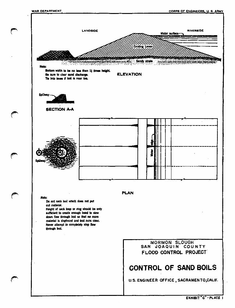
r
WAR DEPARTMENT
LANDSIDE
Note:IlottDm width to be no Itu than It lima MJatrt.lie sure to clear sand dllctwp.TIl Into ... If boll II nair toe.
SpUhr:""SECTION A-A
CORPS OF ENGINEERS U. S. ARMY
RIVERSIDEWater surflco
ELEVATION
--~- -------~---------
- ~_. --------------------I I
-!-- -----------~--------I
PLANNote:
Do not sack boll which does not putout material.Heilht of GICll loop or rilll shouIcI be onlysufficient to create enouah head to slowclown flow throush boil so that no moremalerial Is displaced and boll runs clear.Never attampt to completety stop flowttlrouah boll.
MORMON SLOUGHSAN JOAQUI N COU NTY
FLOOD CONTROL PROJECT'
CONTROL OF SAND ~OILS
U.S. ENGINEER OFFICE. SACRAMENTO.CALIF.
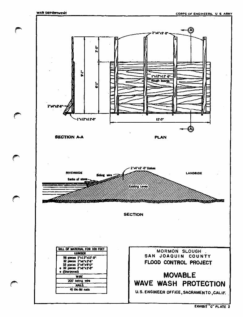
•..."
•...fA
•"xl2"lI2'.{f'
CORPS OF ENGINEERS. U $. ARMV
SECTION A-A
RIVERSIDE
8lU Of MATERIAL fOti 100 fEfTWMW
156 pioca •"l12"a12' .0"32 pIecoa ........2'"..32 pieces rx4"l9'.0"
• 32 piKes 2"114".2'.cr'• (SMtpentd)
WIRE.200' bllina wile
NAlLS4t 1bI.-8d nIIII
PLAN
LAND8ID£
SECTION
MORMON SLOUGH.SAN JOAQUIN COUNTYFLOOD CONTROL PROJECT
MOVABLEWAVE WASH PROTECTIONU.S. ENGINEER OFFICE. SACRAMENTO ,CALif..
EXHIBIT "c" PLATE 2

CORPS OF ENt.NEERS U. S. ARMY
Waterside edge of levee crown
Tie wi re around gatheredPolyethylene to ovoid tearing
II I\ \~ \ \
- --:..-=t").,..,.,.,;;:,..~-",= =--- - ~-~~~~- - - _--.-~~=;, =---~..' \ C
Filled sacks wired to stakes as needed______ .....!yOhol.
//r'
",..,~'
CORPS 01' I.NGINEEltS U. S. ARMV
1ColI: .CriIlI ClIftIIrUCtId of clouJlIt IbIcMIu ttA1.......14'00" 111m... Hili .. III1Inellaoa
. wItb l40d IIIIL £ada IntllllCllDn of .aaMCliIOIY futIned btJ • Iaap~ No. , ....1liII~ twlat8d.
130 pial 1"14".14'00"RE
30' o. 9 wInI
MORMON SLOUGHSAN JOAQUIN C'OUNTY
FLOOD CONTROL PROJECT
CAVING BANK PROTECTION
U. S. ENGINEER OFFICE. SACRAMENTO. CAlif.

• WAR DEPARTMENT COHPS OF E.NGINEERS U. 8. ARMY
SECTION
6'.(1'
FRONT ELEVATION
BILL Of MATERIAL fOR 100UNEAR FEET OF LEVE£
WMBEft26 pItceIl"a12"Xl2'.q"17 plica 2".4".10'.(1'
• 17 p/tCeI 2"14".6'.(1'• 17 .... 2"a4".2'.o"•
NAILS1 /II. .ad naiII2 IbI.·l6d nalls
SANDBAGS1100 baSI
MORMON 'SLOUGHSAN JOAQUIN COUNTYFLOOD CONTROL PROJECT
WMBER AND SACK TOPPING
U. S. ENGINEER OFfICE, SACRAMENTO. CALIf.
EXHI8tT "c" PLATE 0

CORPS OF ENGINEERS U. S. ARMY
r LEVEE CONSTRUCTION REVETMENTS
ELEVATION
uno ,DA "Wlll""" IANIl I'llDlf.CfIOll 10 PIlIV"NT UtIOIIlcunIHG AND GOIt'''QL 01 ~s" Of fLOOD ,",""ILl.
MORMO~N SLOUGHSAN JOAQU'IN COUNTY
FLOOD CONTROL PROJECT
INSTRUCTIONS FORPLACING SANDBAGS
~J(t:AVAT~ RJR IKJTfQM «J(IIf#
SECTION
INSTRUCTIONS:I 'ILL IAMOIAGI aIS 'ULL, ANO III Cll'IN IND.a· TUca IN IOnow GORIUAS Of OAO MICII "WHO•t ""AGI IAOI '1IlPlHOlGULAR 10 llLOPC •4 LAI 1I1l11CfIP AND "(AOlA couaSf.O WII" CtlOICIl AII0 ...
eu»t III. 'l1li1'·
fiLL MATERIAL;
THl CllAL MAtllllAL ,Oft 'ILLIIIG liAIIO IIAGI II A '111& IINIO ORCOAASl SILt. AVOID, A$,.lICIt A$ POSSllIl&, THI UIl 01 COAA5f;GRAVEL AWl HlAVI c:LAYS.
ESTIMATING DATA:
I AlIllWll wf.lGltT Of (ACtt 'ILUO SAN08AO AI'l'IlClllIMATI£.YULU.
I· AI'f'fIOIIIllAln' uo ""'OIlAGI AIlI IlIQUIAlO ,DA lAGIt100 so ... Of IUflfAU TO Of. fllYllm.
ELEVATI°tf
SKETCH
llAlllOeAGCllHG uKD 10 I'lllV1HI OVllltOl'l'IIUi 01 UISIIIIG UWlSallO '011 llllAllllllG 'UlClO WAtlll1 WKlAl liD 8AI:ll''''' IlAUIlIA&. ISINAILAILI.
iNSTRUCTIONS:L 'IU. IAIIlllIAGIlla 10 a/) 'u\L IUT UAVl IIlOUGH 'LA' 10
tuU UNOIA. 00 NOT Til. ~VC lllDS CIl'''II... fOIl lIIIGHTl Of I 'OOT AIIIl Lilli, 1.10' • llIIGU COUAUI
• '" 1ACIl' LlICOT..WISC" SHOWN III SIlITCH·A'.U.OW.I. fOIl KlIClH11 GAUnA fltAH I '00' ,""AU AI IIIOI'AIIO
• IIIl'Qt'.' 1lLOW•.. ..... lIAOI _ PLACCO 'LAnlN OUI AIID 'ILL \I0IO$ IIY
M&IKlIIO lAGS WITH fllT IoIID VIGClllOUSLY 'AAIU' UCH CllUlISit1I1IC uva Ke'lllN. '111111 All P'IlIIo1lLY ~I"" OI'PAllOIIfOIl NOVIlIlIIO' UYllllllGtt WILL III AllMI'ClMClUI TO a'pAlI'OISlBU AIIIl TO IHSOM "'IIILITY Of ""ION. LOOSlLY I'UCIOIAIIIIIAGI IIlPIlOPlIII.Y ""'O TOGITKP MAY filS"'" 1M 'AlLIIIlIMO CIU8& WllClUI llAUAM.
LEVEE SECnON. HIlt tClGHI$ .. CIIClII 01 flU AOOVl IAPPflOll. ) ••••• KOU»
..... 1IA1TIIl AIIO lUlU» ClIt THI lIIAJ AI llIOICATlO III OAStlIOUlIU AOOVl. ALTlIlllATC IlCAllIA GOURHS IIIAGI PUUO aIOSIWlS(lAIIO ItRlJQlEA CIllURIlS IGAGll PLAC&O LIItG'hmIlI.
SKETCH B
ESnMATING DATAl, AVPAC!l WllGltT 01 IACIt 'ILLID SANDBAG. APPROli. 10 Lal.,. APf'lIOlIdoIATlLI 1000 SANDIIAG$ Alii "lQUlll"O 'OfllAGit 100
lIQ. ". 01 lUll'A" ttlllGlt' MUL11l'Lg0 0' IIIItAIICII.
U. S. ENGINEER OfFICE, SACRAMENTO, CALIF.
f;XHIBIT "0" PLATE 6
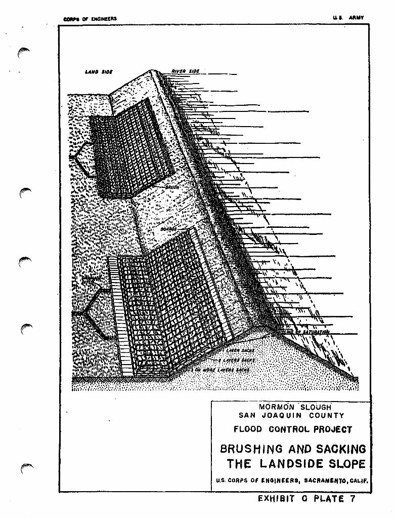
CIDRH or lN4lHltRS u.'o AI'''.
MORMON SLOUGHSAN JOAQUIN COUNTY
fLOOD CONTROL PROJECT
BRUSHING AND SAOKINGTHE LANPSIDE SLOPE
U.S. CORPS Of ~NGINUR8. SACftAMI'no, GALIf.
EXHISIT 0 PLATE 7
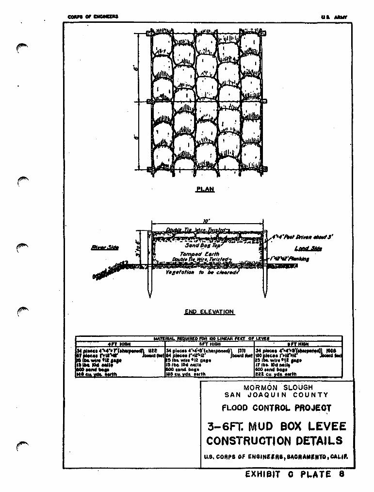
UI. MtIt
PLAN
ENP ELEVATION
:nAIAL U1A£D f'OA 100 L1NrAR 1lt1' 0' LIVE,., H
MOORMON SLOUGHSAN JOAQUIN COUNTY
FLOOD CONTROL PAOJEOT
3-6Ft MUD BOX LEVEECONSTRUOTION DETAILS
EXHlfllT 0 P'-ATE 8

}u""""""""""""" ..."..,,,,,,,,,.A
1 "uOt
Land Nt!
MORM-6N SLOUGHSAN JOAQUIN COUNTY
FLOOD OONTROL PROJeCT
,•.-.., BOX BULKHEADCONSTRUCTION DETAILS~F .
EXHIBIT C PLATE 9

"ANIl 61.
:.:••:.... • '.:,:.:. 't .'.", .:. -:••,: ~'::\.:.::.:••••• "t, :.'. ,.....: •••. :. :.". 't: ....':.
",-.----'\'
\\ .\
\
\
MORMON SLOUGHSAN JOAQUIN COUNTY
fLOOD OONTROL PROJECT
METHOD OFDRAINING LEVEE SLOPE
U.S. CORPS Of ENGINEERS, SAORA"ltnO.G~LI~
EXHIBIT c PLATE to

EXHIBrl D
S'OOGESTED SEMI-AmroAL REPOM' FOBM
EXHIBrr D

TO: The District Engineeru.S. Arrrry EngineerDistrict Sacramento650 capitol AvenueSacramento, California
Dear Sir:
(l May 19 )(1 Nov 19 )
. The semi-annual report for the period (1 May 19 ) to 31 October19 ) (1 November 19 to 30 April 19 ) Mormon Slough Project leveesand'Channels, San Joaquin, is as f~llowS:-
a. The physical condition of the protective works is indicatedby the inspector's report, copies of which are inclosed, and may be summarized as follows:
(Superintendent's summary of conditions)
It is our intention to pertorm the tollowing maintenancework in order to repair or correct the conditions indicated:
(outline the anticipated maintenance operations tor thefollowing 6 months.)
b. During this report period, major high water periods (watersurtace in Mormon Slough reached or exceeded the reading ot 12.0 on theState Department ot Water Resources gage (located on the lett bank of MormonSlough about 1,400 feet upstream from the Escalon-Bellota Road Bridge)occurred on the tollowing dates:
Dates Maximum Elevation
EXHIBIT DSheet 1 of 2
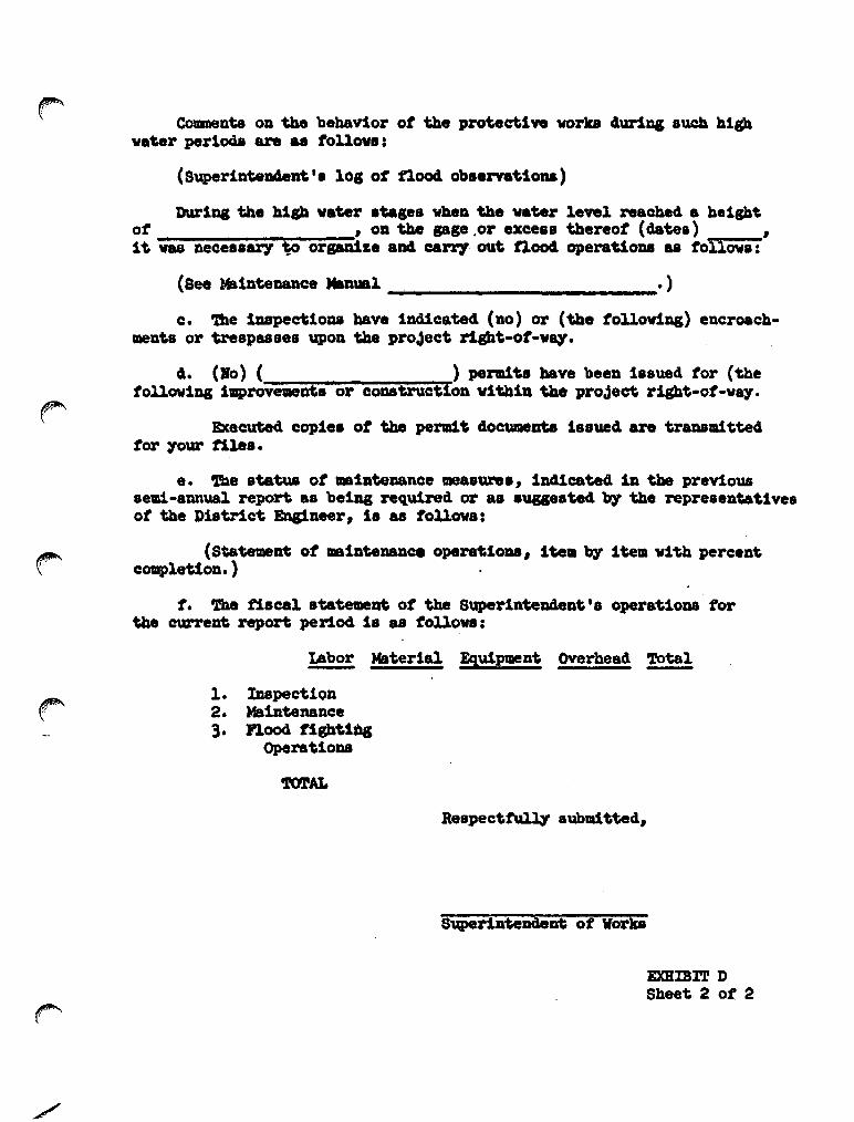
Cementa on the behavior ot the prouctlve vorks 4ur1D& such Alghv.~r perloQa are as tollow.:
(Super1nwD4eDt '. 101 ot flood ob.enatloDa)
»ur1Do1 the hlp vater stages vhen the vater level reached a A.1sh~
ot , on the pge ,or excess thereof (dates) ,1t vas llecessa17 ~ orjiiiize aDd. ce.rry out noaA opera"ioDB aa tollowlI:
(See MalnteD.81lce Man\Bl • )
c. 'l'he inspec'tioDII bave lndicated (no) or (the folloviDg) encroachmen"s or trespasses upon the proJec't riP"-ot-vq.
4. (Bo) ( ) pendt. bave been ll1sued tor (thefollowing improvements or cODBtructloD wlthln the proJect right-ot-way.
Executed coplea ot the pend.t documeata 18sued are traDBaittedtor your tiles.
e. 'l'11e statua ot _laW_Dee measurea , ln41cate4 ln the previousaem-annual report as being required or as auge.ted'b7 the repreeenta"lveeot the ])1etrlct Englneer, i. •• tollows:
(Statement ot ain'temnc. opera1fioDB, i'tea'b7 item with percentcompletloD. )
t. 'lhe t18ca1 statealeDt ot tbe Superin'teDdent's operatioDB torthe current report period 18 as tollow:
Labor Material Equipment Overhead 'ro'tal
1. Inspection2. MalnteDaDce3. nood tigb"l_
Opera"loDB
Resp8cttulq 800udtted,
SuperiD'teDdeDt ot Wora
EXHIBIT DSheet 2 ot 2
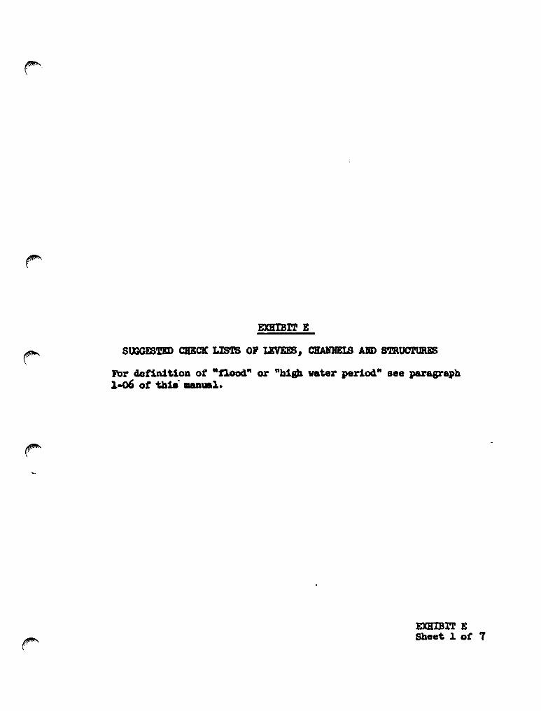
For definition of "flood" or "hip vater period" Bee paragraph1-06 of t.hi.....1.
EXHIBIT ESheet 1 of 7
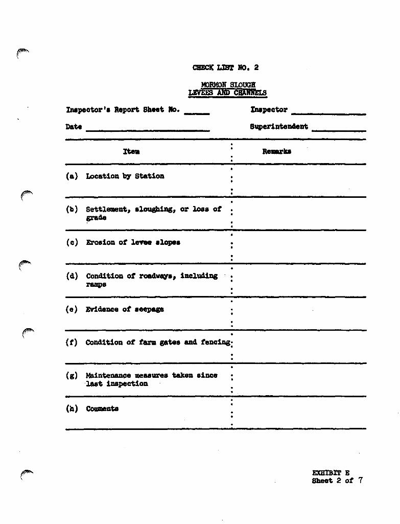
CIIECIC LIft 10. 2
Iupeowr'. aeport Sheet 10. __Date _
lupecwr _
8vper1DteD4eDt _
rtea Re.-ra••
(a> LocatioD b7 Station
••
(b) SettlemeDt, 81o\18b1aa, or loss of •grade •
EXHIBrr ESheet 2 of 7

/
DSTRUC"rlom FOR COMPLE'!'!m SHEET 2, EXHIBIT E(To b. prlliteCl on back ot alieet 2)
Itea (a) ID4icate levee station ot obael"VaDce, obta1Ded 'b7 paciDgtroa Deareat retereDCe poiatJ iDll1cate risht or lett bau.
Ite. (b) It sufficient settle_nt ot earthwork baa taken place to benoticeable by Y1sual observation, iDC11cate eaoUDt ot 8ettle-.eDt in tenths ot a toot. It sloughing baa caused a changein 810pe ot the nbaDkmeDt sectioaa, 4etel'll1D8 the DeW slope,Bote areas where erosion or gulqiac ot the aectlon baa occ\IJTed.
rte. (c) It sufticient erosion or gu:lqtag ot back tace ot back toe otlevee baa taken place to be noticeable 'b7 'ri8_1 iupect10n,lDd1cate area attectecl aDd depth.
Itea (d) Bote an.y aa\ltral chADp 1n al\1 section ot roadvq or J'8IIP8.ID4Jcate a~ 1ua4eqaaq 11l 8UJ'tace c1raiaap 87ate••
Itea (.) Incl1cate alV' .n4eDce ot seepap tIaJ'ou&b the nbaDkmeDtaectioD.
rtn (t) Indicate the .el'Y1ceabl1lty ot all tara pte8 across the emb8DlaDe1lU aDd roaclvq, aDd 1nd1cate it repaiDtlag i. required.
Itea (I) Incl1cate ulntelWlce measures that have beeD performed aincelast ill8pectiOll aU their col141tlon at the ti_ ot We InSpectiOll.
%tea (h) Record oplnion, 1t arI7, ot contribU'tar7 causes tor conditioDBobsene4 and alao a:t1¥ obaern..UOIl8 DOt covered UDder other·colillDa.
1I1lB: ODe caw ot the Inspector's Report 18 to be IBlledto the D1atrict Bngineer 111D8d1ate~ on completion, andODe cOW i8 to be attached to aDd aubll1tted with theSuperillten4eDt's s.ld.-ann\l&l report.
EXBIBlT ESheet 3 ot 7

CHECK LlBT JrO. 3
CJWmEL AIfD 810ft-Or-WAYMORMON SLOUGH
Iupeeto!' -. Report aben 110. __
Date _
••••
Iupector _
Super1DteD4e1l1; _
(a) Name ot cbannel UI4 location'b7 statlons
(b) Vegetal grovtb In cb8nDel
(c) Debris Md retwse In cbam1el
(cl) New coastructlon v1tb1nrigbt-ot-wq
·•••••
••••
·•
••
.,..,"
(. ) Extent ot aggradatlon OJ'degradation
(t) CoDd1tloD of rlprappec1 8ectlon:••
(g) Condition of briclgea
••
(b) Measures taken .ace laatinspection
(1) CoaIeats
•••·••••••
EXlUBl'r ESheet 4 ot 7

IRSTRUC'l'IONS FOR cx)MPLE'l'DO SBEE'r 4 EXHIBIT E('ro be prliltiCl 011 bick of sb:et 4)
Item (a) IDdicate atation ot oba.rvation obtaiaed b7 paciag trOllaearest reterence point.
Itn (b) Rote Dature, extent, aDd ai&. ot veptal growth within tbe11111108 ot flood flov cbalmel.
Itell (c) Rote nature and extent ot debria and refuse that; Idght causecloggiag ot the conduits ot the irrigation Intake works, fouliDg ot the '-inter ptes, or the bridtea oYer the chaDDel.
Ite. (d) Report artt cOIl8VRC'tion aloll8 the diversion channel or abovethe cl1version cbauel' or above the diveraion works that basCOllll!l to the attention ot the ill8pector and that Idgbt atfectthe tunctioD1D& ot the proJeet.
Itell (e) IDd1cate artt change in grade or alignment ot the cbazmels,either b7 depoaition ot aed1lDelit or acour, that i. noticeablelr,( v1a\l&l 1upection. Eatlma'te .lIOut eDd exteut.
Ite. (t) IDd1cate a~ change that has taken place in the riprap suchlUI disintegration ot the rock, eros10n, or movement.. ot therock. Iote tbe pl'8aence ot vegetal grovtll 'tbI'ouab the rlprap.
Ite. (S) Rote 8D;V' damage or aettleme. ot ~e tootinp ot the bridges.Indicate coDd1t1on ot wooden structures and 1t repaintiDg 1&required. Ind1cate coDdlt1on ot bridge approaches, headwalls,and other appurtenances.
Ite. (h) Indicate mainteDallce meaaures tbat have been performed aince~e 1aat inspection and 'their collCUt101l at t11118 ot till.'1DBpect101l.
Itea (i) Record opinion, lt any, ot contributor)" causes tor conditloDSob8erved, alao 8rtt obaervatioDa DOt cOYered under othercolumna. .
1O'lB: ODe copy ot the Inspector' a Report 18 to be _11ed tothe Diatr1ct Engineer laDecl1atel)t on complet10n, aDdone can is to be attached to aDd aubll1ttecl Vith theSuperiatendellt '. aell1-aDDual report.
EXBIBl'.r ESheet 5 ot 7

~.
~e COIIIIIIeDta
-gI~
'&Q)
~Repair ;Measures taken Pt
I-- since last $.tGJ
~ inspection §Condition ot ir1gb't-of-way 0
r-o adJacent to iCDt, structure ·asrn
Condition of !.concrete ...-4
~
....... headwall or .-..~ invert paving 0
Os::a
Damage or ......'t;settlement v
r-' ot pipe or .s~ conduit
Debris orr- other~ obstruction
to flo"r-. Banket-- Location by~ levee Mile
EXHIBIT ESheet 6 ot 7

IHST'RUC'l'IOHS FOR (X)MPLETDG SBEE'l' 6, EXHIBl'l E('l'o be printed on back ot sheet 6)
(1) Enter station ot aU etructure. udal' Col\llllll Ca) tor check list.
(2) IDapect inlet, barrel, aDd outlet tor accUDNlation ot secUmeDt,rubb1ah, aDd veptal matter. IIote condition UDder Column (c).
(3) . It any settlement or damage to the pipe, barrel, or invert ot tbedraln has occurred, estimate the location aDd amoWlt. Bote particular~ it aD1' backfill bas come into the pipe or been disturbed.Record observatioDB WIder ColUIDD (d).
(4) Inspect the concrete portions ot the structures tor evidence otsettlement, cracka, "pop-outs", apaces, abras1ve wear, or otherdeterioration. Record COnditioDB UDder ColUIIID (e).
(5) Inspect backfill area adJacent to structure tor evidence ot erosloDcaused b;y overfiov ot the 4ra1Dage structure aDc1 Dote coDdltloDBin ColUlllll (t) •
(6) Under Colwm (g) 1nd1cate physical _asures that have been taken tocorrect conditions reported1n last iDBpectlon, aDd their coD41t10nat time ot thi8 1D8pect10n.
(7) UDder ColWDll (h) record opiD1on, it any, ot contributory' causes torconc11t1oDB observecl, alllo aD7 ob8ervatioDB not covered UDder othercol\llllDll.
(8) A cOW ot the inspector'a report i8 to be mailed to the DistrictEIIg1neer iUllD8cUate~ on completion, and a record caw .hall beattached to the Superintendent'. ani-annual report.
EXHIB1'l' ESheet 7 ot 7

EXHIBIT'
LETTER 01 ACCEPl'ANCE BY THE STA'l'E RECLAMATION BOARD
EXHIBI1' F

Co
py
The Reclamation Board
State ot california
Cop
y
JAN 13 1969Refer to: 4130.50.101
District EngineerCorps at EngineersU. S. Army650 capitol Mallsacramento" california 95814
Dear Sir:
Reference is made to your letter of January 9" 1969 concerningtransfer to the state of Ca.lifornia of the Mormon. Sloogb Flood ControlProJect" Unit No.1 (Jack Tone Road to Bellota)" for maintenance andoperation.
This work was constructed in accordance with Specification No.3321" Contract No. DAai05-68-C-0060,, Drawing No. CA.-4-48.
The Reclamation Board" at its meeting of January 10" 1969"formaJ.l.y accepted the above referred to work for operation and maintenance"with the exception" as indicated in your letter of transfer" that thisunit of work is subject to additional work as appropriate to cover itemsfound deficient at the t1me of the Joint inspection of Ja.nuary 1" ~969.
Sincerely yoors"
/s/ A. E. McCOLIAMA. E. McCOLIAMChief Engineer and
General Manager
EXHIBITFSheet 1 of 3

Cop
y
The Reclamation Board
state of california
Cop
y
oar 21 1968Refer to: 4130.50.102
if1!I"i't'
District EngineerCorps of Engineersu. S. Army650 capitol Mallsacramento.. California 95814
Dear Sir:
Reference is made to your letter at August 19.. 1968 concerningtransfer to the state of California at the Mormon Sloogb Flood ControlProject.. Unit No.2 (mouth at Diverting C8.Dal to Jack Tone Road) formaintenance and operation.
This work was constructed in accordance with Specification No.3356.. Contract No. DA.CW05-68-c-0020.. Dra.wing No. 3-4-147.
The Reclamation Beard.. at its meeting of september 6~ 1968~
forma.lly accepted the above referred to work for operation and maintenance.
Sincerely yours..
lsI A. E. McCOLU\MA. E. McCOLIAMChief Engineer and
General Manager
JBMacC:pa.
ElCKIBrI'FSheet 2 of 3

THE RECLAMATION BOARDSTATE OF CALIFORNIA
Co
py
District EngineerCorps of Engineersu. S. Army650 Capitol MaJ.lSacramento, California 95814
Refere to: 4130.50.104
Dear Sir:
April14, 1970Co
py
Reference is made to your letter of October 30, 1969concerning transfer to the state of California of the lobrmonSlough Flood Control Project, unit No.3, right and left banksof the Calaveras River from the San Joaquin River to the McAllenRoad Bridge for maintenance and operation.
This work was constructed in accordance with SpecificationNo. 3600, Contract No. DACW05-69-C-0078, Drawing No. 3-4-148.
The Reclamation Board, at its meeting of April 10, 1970,formally accepted the above-referred to work for operation andmaintenance.
Sincerely yours,
/s/ A. E. McCOLLAMChief Engineer and
General Manager
EXHIBIT FSheet 3 of 3


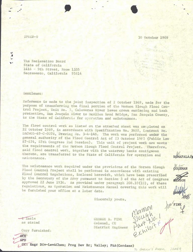


EXBIBl't a
8AMPLI PERMrr
tor \188 ot.
RIGB'l-OF-EJrmr
EXHIBIT G

~~ ..
(kime or Levee commI••lon or Clti)
(toeatlon)
Pel'1l1ss10n i. hereb7 granted to:
(Na_ ot ifiIIi or liidIVldual )- (Ad.dr8•• )
'1'0: (Describe in ~es spaces the proposal, 1nclwl1ng JdDCl aDd type otconatruc1;ion, purpose intended, locaUon ~ statioD1ng. IDd1cate passagevs::I prov1ded 'by meaDS ot p'tes, etc. Use separate shee'ta it Decesaary,i4entit71D& each ~ reterence herein.)
PJ'ov1ded that:
Upon teraa1nation or expiration ot this perm1t (whether by vol~tary
relinquishment by the grantee, by revocation by the grantor or otherwise)the grantee shall remove all structures, i111provementB, or appurtenances .which _y have.been erected or constructed UDder this permit, and shallrepair or replace aD7 portion ot the flood pro'tec1;ion structure or rightot-way which 1IlaY have been da_sed by his operations (including grading andseeding, or sodd1ng, it Decessary), to the satistaction ot the grantor.
The s'tructure or operation tor vhich this perm:1t 18 issued shall be1181ntained by the grantee in such ....lmer as shall not injure or damagethe flood pro1;ec't1on stru=ure, or interfere vith its operation and11811ltenance in accordance with regula'tioDB ot the Secre'taz7 ot the ArrIJ:I.
i'he struc'ture or operation covered 'by th1s permit III8Y be damged, reIIOved or destroyed by the grantor in time ot flood emergency it such ac'tion18 determined 'by the grantor to be necessary in order to preserve lite orproper.ty or prevent damage or impairment to the use ot satet)' 01' the floodprotection struc1;ure, aDd the grantor shall DOt be 11&ble to the grantee torsuch damage or destruction.
EXHIBl'1' GShee't 1 ot 3
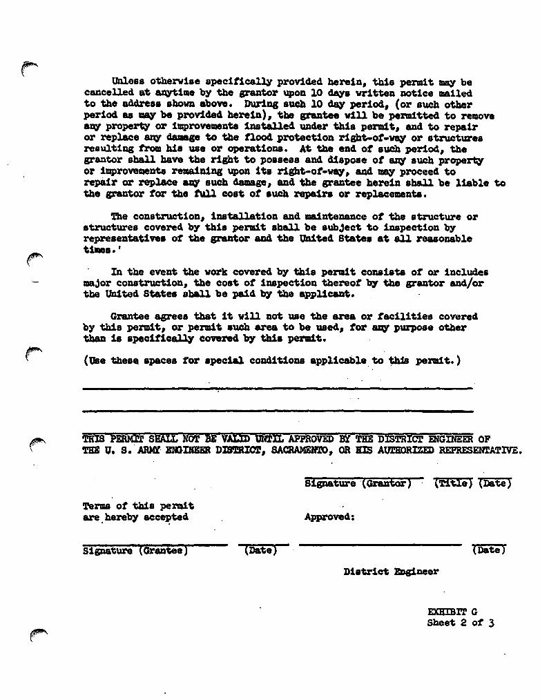
Unless otherwise spee1t1ce.ll¥ provided herein, this pena1't JIJIq beeancelled at u;yt1l1e by the arantor upon 10 days vr1t'teD notice _11edto the address sbow above. DuJ'1q such 10 dq period, (or such otberperiod as ~ be provided herein), the grutee will be pel"ll1tte4 to removea~ property or improvements installed under this Perm1t, and to repairor replace ~ c1aaIap to the fiood protection right-ot-vq or structuresresu1t1ag tJ'oll his Wle or operations. At t.be eDd of such period, thegrantor sball have the right to pOlseas and d1spose ot ars:I sw:b propert7or improvementa rella1n:1na upon its rigb't-ot-way, and .., proceed torepidr or replace arq such clamage, and. the grantee herein 8ball be liable tothe grantor tor the tuU C08t ot .uch repa:1ra or replace_Dta.
The construc't1oD, installation and. ma1ntenance ot the s'tructure or8'tructure8 covered 'by this permit shall be 8ubJect to 1napect1on 'byrepre8entative. ot the srantor aDd the UIl:1ted State. at aU reasonablet:1.s. r
. In the event the work covered b7 this permit consists ot or include._Jor eonstrw:'tion, the C08t ot iMpection thereot b7 the grantor and/or'the t1n1ted States 8ball be paid b)" the appl1c:ara1;.
Grantee agrees that it will not use the area or facilities coveredb;y t.b1s pel"ll1t, or permit such area to be used, tor 8ZI¥ p\II"p08e othertbaD 18 spec1t1calq covered. 'b7 thi. pentt.
(Use 'theae spaces tor spec:1al coDditioDS applicable. to~ pel"ll1t.)
'rHIS PERMrr sHALt NOT BE vitID UtflIL APPROVED Br THE DISTRICT mGINEER OFTHE u. S.· A1U({ mGIJiBiR DIS'lRIO'l, SACRAMEIfm, OR !lIS AurmRIZED REPRESENTATIVE.
s1iD&ture 'CGi"8DtOi') . (HEl.) (Da'te )
Terms ot Wa pe1'll1tare. hereb)" acc8]?ted
S:l.gna'ture (GranGe) (Date)
Approved:
(Date)
EXBIBl'l' GShee't 2 ot 3

RIDULATIONS GOVERNING ISSUANCE OF PERMITS FOR mE OFRIGlfl'S-OF-WAY FOR FlOOD PROTECTION PROJEC'rS
As the tlood protection works and rights-ot-wq are owned b)' theLocal Interests and will be operated and maintained b)' them in accordancewith the Regulations ot the Secretary ot the Arrrq, and issUr&nce ot an;yperaa1't8 to \188 t1::&e reatnGt10n ~t DO .\lab peZ'll1'ta ~ 'be to."'84 w1t.boutthe approval ot the District Engineer, as stated in Paragraph No. 208.10<a) General, (5) ot the Regulations, a coW ot which is attached hereto.
Applications tor use of the rights-ot-w~ should be addressed tothe City or Levee Commission having jurisdiction over the local floodprotection project. '!'he City or Levee Commission will then forward tbeapplication to the District Engineer, of the U. S. A.rTay Engineer District,Sacramento, Cal1forn1a, with its recommendation, with reasons for suchrecommendation. It is suggested that the application and recommendations'be forwarded with a draft coW of the permit, in order that all objectionablefeatures ~ 'be eliadnated prior to its protfer to the applicant as thisma,y prevent adsunderstandinga and arguments. It for au:! reason it isdesired to forward the permit itself without this intervening step,fiye copies ot the proposed permit should be included on which is statedthe exact use of the ri&hts-of-w~, for which permission is beingrequested, together with any condition or restriction of the peradt. Thepermit should be signed b)' the applican1i and an ottic1al of theLocal Interests. A drawing, sketch or detail plana as ma,y 'be requiredto show the exact location, nature of work and proposed method ofconstructlon should 'be attached to each cOW of the permit. It thepermit is approved b)' the District Engineer, three copies will 'bereturned. 1'h1s w1ll enable each part)' concerned to bave a -eaw of theapproved perm1.:t.
In au:I case where a permit is requested for any purpose which mightcause disfigurement or damage to the flood. protection rights-of-way orstructure in its erection, use, or removal, it is suggested that theapplicant be required to post a 'bond ot sufficient amount to protect theLocal Interests trom 8I\Y cost of repair or removal, am to guarantee faith:f\Lperformance of the perm110 conditiona. In such cases the permit shouldstate the amount and conditions of the 'bond.
In cases involving major construction or other work which ma;y d1rect~·
affect the flood protecu. on structure, it will be necessar,y that theUnited States inspect 'the work and too Local Interests ma::I also desire 'toinspect it. As stated in the permit form, such inspection will 'be at theexpense ot the grantee, and this should 'be called to his attention. Exceptin cases of known financial seeurity, arrangements should be made with thegrantee tor an advance clepoait or bond to cover such costs.
There 'is attached hereto a copy of a permit form which has been succe66~ used b)' a number of cities and levee comadttees.
EXBDl'l' GShee'" 3 or 3

C-O-p-y
April 17. 1984
Navigation and Flood Control Unit
The Reclamation BoardState of California1416 Ninth Street. RoomSacramento. California
Members of the Board:
445-695814
~"..
This is in regard to resolution of September 1. 1983providing assurance of local cooperation by your Board foremergency bank protection work to be accomplished by the Corpsof Engineers under authority of Section 14 of the 1946 FloodControl Act and Section 2304 (2). Title 10. U.S.C.
The authorized work was completed on April 13. 1984. inaccordance with the Contract No. DACW05-84-C-0041 and +Specification No. 6844. and consisted of about 100 feet ofgabion bank protection along Mormon Slough right bank at-JackTone Road in San Joaquin County.
The completed work. together with the waterway bankscontiguous thereto. is hereby transferred on April 16. 1984 tothe Reclamation Board. State of California. for operation andmaintenance. in accordance with Title 33. Part 208. FloodControl Regulations enclosed.
An operation and maintenance manual for the completed workwill be furnished your Board at a later date. This manual willfully outline your responsibilities as the operating agency.Written acceptance of the completed work is requested.
Sincerely.
Arthur E. WilliamsColonel. Corps of EngineersDistrict Engineer
Enclosure
EXHIBIT H
ADDITIONSPage 4 of 4December 5. 1984

,
,i
E'L,.c.N
c',,'
F',le No. 3-'-13=143--
'''e~1
LEGEND B NorE
~ S,olle pl(!,ecri(!n
TftJicol .f1C1;QII. 311d,,,ftft!'lltt numbtr.
..._PQW~I pole
r~r gener-1I1 nO!('!5 ~~" ~h~~t fJlJm~~1 !4C/C:
flC::==t __ 5p(!'-'
-------,,1,:iOc'B5 - TYPE PA.MP'
.~,
~\ S u '"
A'/en!/;'n /5 d(nd~d.l~ rl<,7!~rc{/5 j;~!/; .'-",;",~
ol'ld f)l1dugnc'l1d, /ljI;'g wir:,in th~ IJre~ (J1rn9 Ihj~rl ~(MJ:. (~rt .hr:;li b~lqk,YI by !M :-:'fJ/rucfor 1'10/ /~
11!'snp!Hrmt
NOTE'
,.,1-\"'''-'
,'I
iii SAFETY PAYS iii(Orlo,+ ruct Ion and_ Cho')nel \mprc;vemerd --------==-fopo GRA P
--I
" .,y,<:i;":,lAd,' //'--'---__.. 'l.-..;-'
>clt" r~.{0f":>/'----, -;-. ~",y "\~,;:</ ,~+,.~_' ;' ,;.~ _, '" I., ". , ." ·~ti ~~ . -, - ""-,.,,,.
~_ " '7-,';•• ,,,,.
\ " ." " .,' '1"" " ..." ~ " / /," ," ",,,~,,,// ~ =,;.\C, ., ~_,,~,,~c'c _ .' ,~> ,,' "• C •••••• c: >-....... .' ..A S?~~,~~-~ </,-1'"'' V·f;l~" ,<o~ #,
,.:7_~-«_-.3~~ __ 'x, V 5tc,,'~'c ' 'I, J""'" -<:\,~" f -,,_. ,. _"v."'" ",,". "., ., : "', .' ,,~." ' ,_ ::mr~~"'-:" .)Y:,~~"m,~"~f.H1WMWID.ltg I n- 1~~ ~<t~\" c,' 1;0'/ /"-' p~ -----!':\f~1'I' ,1.'f"--~,"' .... ,~.. ,'" ., ,.---_ ,'\ ,!/~ /~.~;;~!~.~ "~,,,,,"',,,,.,, fr'- cc, ' :i' , ::-.. • ;' '" -~-H " ~p ,~~,u.G.vote"lln. )1.v~'!1 I,~~'o -~ ," - ~ '- -, / "
• '" ' " C • A"""" ", " ; .-". ~ ,. - c, 7-" "...7.:-'-" , • ..-' "" ,,/I /. c - ,.-'>,- .,1; "'"""0",'0'''''- >;~'-::-- ...--0,.,'7,1;" " ~+ '0' -~: p~""""' .:._ I' ~, _>""""",q,, c., " " !:: ",'rVGerT'eter I r____.--,.'" _~" /' I -,.:,.:!' 1
0
.. ~~~ ~~5URfA,; _' .. ' --4,,:C'. -. v,- - -- ~, ., ", '¥" -; '," ,,'_ ' .. ', ••' • , , ..,..,," "0" '"''
II '" i', c,< f%;,---""" --'0,"' " ..-- ,~, " ""
,0',"'('j
li\
£
CROCKER CITIZENS Ill.TlON!Il
.1,Re"'~,e (I"soer I~"eCU$ per""'.1 p,~oe"yl"'p~,"0(0..-0'. eo ~mb,~ ",,,~l .. Re~o',~ "u ~'",e ,I, trees f'o~ oro_,' o' e:"st"'i< I.',ee.
~ ~
_ r'",e ,II remove, ,,~ """~ ,t~m,oo "'0' '1"'0'",",.,,",.,·,1~' .... ~"",," 'e',e~ l~ Or~, ,1e ,," .". I:
,1. ~~;':';:I'~ :~~'';:~n~ ~;:"; n~'l"t'" bQ~r d;~ i ~f~~:laSL" ace 4' , >0R""~,,, ,,0 W"~t, ,·~be' i<ale "",(,,~", F"','," 'I '''~,:,,t,100,,1 ,'"og ",t~ "c,~" ,','"" :,cor, 50 fH' '",,~roa.
'CT. Re, ,"' A,'e--",~.
"~~O'O d'C '.~o\, :,G,:' c' 'ooce '"", w~\e'f;' Olo (")<' ..
fe'""', L '-,'10" 0\0"'"'' ,. o~ ~H' I~'e''~~'"t',~c' 7:; ,j' cr,O" '''',ce
Remo,e oM ..O"~ ,~,~'orced Co~cfete b.,'d,n9
- - f'lemo.e 0"1 '~o .." sHeer C':I'
.",; 'r'
"'JG ,.
"A'IE~SES'lT'O'j
""lace .. ·' ,.'.
.". " :;:;::,'::;::h~;,;";;;:; ::,;;, ":::;,;,"'::,
/7'-"''''~/
" •• ~ ';! :'
,:<j 'b'
t)
1/, 1~'''[ Jl~-~. -~-'-,oN.JA!4<JJ-!O-,~ "r<r</UA~/4d/J
",,:'" . M()[)I[..i-I';;<o)Jf'lf No,,~"r=;:, ';' ~i"::
.~.', ~SlJ
-·C'~·
!CAI'eRSEc·'!'''N-8'OC
.1, "0' c"~
&'2-9G'C"- -
&'4'30·C- -
&:I'CJD ''[:'' '0 IS.97"C"
'-'j':;'; 'e
,'_(,C-'
2-'<'; '"
o5<G~R'
.1 '9_25 '13" - -
Li\" "jC~
~~,>\
'..
",
-----------
"'E~£"'E>iC£ ,.~~'!"'St ol."\-I3S6 "&$ ~6-~O, 5~-4~L "Go:5,le-L~,~-1 "O'-'N"""Ci~ "~-I~Op<:'':.,Sl·L~_,____ ?1l,""'LL£ ~ "-$~"""O>i'S 53- ItO ",,"S. [1- l0 5~ .','1' ~&, '3 ~ 53-4)1 ~~ " ~ tt.Sd .~ P(;~ ~:,,--4~'-3C) ~"~~~-:;~Q ",s,~----'---.:.,~,1.~-'"
CORN Of" a-IGlNEEM
s,,;o.Vi.1 ,",OT'-!>', I ---...-~
:,~LO~~~e~¥;"o;,\C\~~[~~V'i:::g ~g...,.~~L~;~~~~'i. LgO..",.~;~...Tt~ ..:;~~ ... , to,,';: m
,n;cCI"~£ ',QiE ~B~
r'lId,-R~ -AI',ER,f~ l,!,'--'-.QI:'.. 2-,,1.'.'e-2'0·4",
~ '~~ JJ j JfJl~~.,
J~ "".-", 'H/ii'"""Xj"~.,.'0' '0 .."":,;~'o,, ..~
1
1~ '>__ /1 ,_, /' "'PM''"'L ~_ _,~~_/ r"" d u~-.i:i------------·/"""""
I ",Jh,-,('" ,I:>rok-:;Nc"--- . ~,."'
;I;'';/''_C~-~''''' ~-. ---",-/,/~ ,,/ /'__~ C"C" ~'
'-'" _J/ ,'" /-.-~---- ~-- ~
:p.. ~<:::,.::~:~~~-> %

OPERATION AND MAINTENANCE MANUAL
FOR
MORMON SLOUGH PROJECT
SAN JOAQUIN COUNTY, CALIFORNIA
PART No. 2- PUMPING PLANTS
DEPARTMENT OF THE ARMYSACRAMENTO DISTRICT 1 CORPS OF ENGINEERS
SACRAMENTO, CALIFORNIA

OPERATION AND MAINTENANCE MANUAL MORMON SLOUGH PROJECT
SAN JOAQUIN COUNTY, CALIFORNIA
PART NO. 2 PUMPING PLANTS
LOCATION ADDITION OR REVISION DATE Exhibit G Add copy of letter of transfer dated 19 Aug 1968 26 Mar 2010

OPERATION AND MAINTENANCE MANUALMORMON SLOUGH PROJECT
PART NO. 2 - PUMPING PLANrS
TABLE OF CONrENl'S
Paragraph
1-011-021-031-01..
2-012-022-03
Subject
SECTION I - INTRODUCTION
AuthorizationLocationProject De~;cription
Construction Data and Contractor
SECTION II - LOCAL COOPERATION REQUmEMENrS
Requirements for Local CooperationAssurances Provided by Local InterestsAcceptance by the State Reclamation Board
1122
333
3-013-023-033-043-053-063-073-08
1.;'-014-024-03
5-015-025-035-04
SECTION III - MAINTENANCE AND OPERATION - GENERAL PROCEDURE
Reference to Approved RegulationsIntent of RegulationsPurpose of this ManualDefinitionsGeneral Provisions of RegulationsAssistance to be Furnished by the District EngineerResponsibilities of the SuperintendentInspection Procedure
SECTION IT - FEATURES OF THE PROJECTSUBJECT TO FLOOD CONl'ROL REGULATIONS
l.eveesStructuresPumping Plant
SECTION V - OPERATION REGULATIONS
ObjectivesBasis of OperationRegulationsOperation Procedures Summary
i
4445517
10
121212
14141415

Paragraph
6-016-026-036-04
Number
ABCDEF·GHIJ
TABLE OF CONl'ENTS (Cont I d)
Subject
SECTION VI - MECHANICAL AND ELECTRICAL FEATURES
DescriptionInspectionMaintenanceRecords
EXHIBITS
Subject
Federal Flood Control RegulationsLocation MapStage - Time - Flow Curves"As Constructed" DrawingsManufacturer's DataPhotogrs!,hic Prints of StructureLetter of Acceptance by State Reclamation BoardLubrication ScheduleInspection Check ListSample Log of Operation
it
16182430
Sheets
land 21 Sheet1 thru 3DetachedDetached1 thru 221 Sheet1 thru 41 thru 71 thru 5
.'

""""'"F'\
OPERATION AND MAINTENANCE MANUALFOR ltDRMON SIDUGH PROJECT
SAN JOAQUIN COUNTY, CALIFORNIAPART NO. 2 - RJMPING PlANTS
SECTION I
INTRODUCTION
1-01. Authorization. The Mormon Slough Project, San Joaquin County, California, was authorized by the Flood Control Act approved 2:3 October 1962in Public law 87-874, 87th Congress, second session, loIhich states in part:
"The project for flood protection on Mormon Slough, Calaveras River, California, is hereby authorized SUbstantiallyin accordance with the recommendations of the Chief ofEngineers in House Document Numbered 576, 87th Congress,at an estimated cost of $1,960,000."
In the report of the Chief of Engineers to the secretary of the Army, dated28 August 1962, the Chief of Engineers stated that he concurred in theRecollllDendations of the Board of' Engineers f'or Rivers and Harbors. In paragraph10 of House Document No. 576, the recommendations of' the Board were asfollows:
''Recommendations • • • AccOrdingly, the Board recoDDllendsimprovement for flood control on l-brmon Slough, the Diverting Canal, and the Calaveras River, California, consistingof channel enlargement and clearing, slope paving, levees,gated drainage structures, a pumping plant, railroad adJustments, and appurtenant works; all generally in accordancewith the plan of the District Engineer and with such modifications thereof as in the discretion of' the Chief' ofEngineers may be advisable • • • ."
1-02. Location. The Mormon Slough Flood Control Project is located inSan Joaquin County and in the general vicinity north and east of the Cityof stockton, California. Operation and maintenance of the levees and channels on the lobrmon Slough Project is covered in Operation and MaintenanceManual, Part No. I - Levees and Channels. This manual covers the threepumping plants located on the right bank of the stockton Diverting Canaland tvo precipitation gages. Plant No. 1 is located a short distance upstream from Wilson Way, Plant No.2 is uPStream from US HighwBy 99, andPlant No.3 is located a short distance upstream from Linden Road. Forlocation of the precipitation gages see section VI, paragraph 6-01(d).For further location details see Exhibit B.

1-03. Project Description. Facilities provided for the three pumpingplants are as follows:
Plant No. H.P. Rated Capacity Size Gravity Provtsion ForNo. Pumps c.f.s. DrainPipe Future Pump
1 2 20 8 each 30" x 30" 12 2 125 50 each 48" x 48" 23 2 50 20 each 30" x 30" 1
For more detailed description of the pumping plant facilities see paragraph6-01 of this manual.
1-04. Construction Data and COntractor. Work required to complete thepumping plants was accomplished under COntract No. DACW05-68C-0020 by R.P. Burris during the period from 1 October 1967 to 19 August 1968. Specification 1No. 3356, Drawing No. 3-4-147.
2

SECTION II
LOCAL COOPERATION REQUIREMENTS
2-01. Requirements of Local Coo.peration. House Document No. 576 requiresthat" prior to construction" local interests give assurances satisfactoryto the Secretary of the krmy that they will, 'Without cost to the UnitedStates:
a. Furnish all lands, easements, and rights-of-way, including spoildisposal areas, necessary for construction of the works.
b. Accomplish all relocations and alterations of roads" streets" buildings" pipelines" utilities" bridges" and other structures (except rail-road facilities) made necessary by the construction work.
c. Hold and save the United states free from damages due to the construction works.
d. Maintain and operate all the works after completion, includingthe lower Calaveras River" in accordance 'With regulations prescribed bythe Secretary of the Army.
e. Prescribe and enforce regulations designed to prevent encroachmentof any type that would impair the flood-control effectiveness of the Yorks.
f. House Document No. 576 further requires that Federal maintenanceof the existing stockton and Mormon Channel Project (Diverting Canal) fornavigation be discontinued upon completion of the improvements recommendedtherein.
2-02. Assurances Provided by Local Interests. The Reclamation Board ofthe state of California" by letter dated 13 December 1963" advised theSacramento District Engineer that the Mormon Slough Project was authorizedby the state of California by Chapter 915 of the Statutes of 1963 and thatthe Reclamation Board would, upon request, give the required assurancesto the Corps of Engineers under Chapter 1438 of the statutes of 1963.
2-03. Acceptance by the State Reclamation Board. Responsibility for operating and maintaining the Mormon Slough Project" Un!t No.2, was officiallyaccepted by the Reclamation Board of the State of California by letterdated. 21 October 1968" see Exhibit G. The three pumping plants coveredby this manual are a Part of Unit No.2 of the project.
3
SEm'ION III-MAINTENANCE AND OPERATION - GENERAL PROCEDURE
3-01. Reference to A oved Re ations. This manual is submitted inaccordance vith provis ons 0 t1e 33 - Navigation and Navigable Waters,as of 1 January 1962, Chapter II, Corps of Engineers, Department of theArmy, Part 208 - Flood Control Regulations, Maintenance and Operation ofFlood Control Works, a copy of which is included as Exhibit A, Sheets 1and 2.
3-02. Intent of Regulations. The general intent of the regulations approved by the Secretary of the Army is stated in paragraph 208.10(a)(1)as follows: tiThe structures and facilities constructed by the United statesfor local flood protection shall be continuously maintained in such a mannerand operated at such times and for such periods as may be necessary toobtain the maximum benefits. tI
The princiPal mission of the Corps of Engineers, during flood emergencies,is to insure that flood control works are properly operated and maintainedand offer technical advice to enable local interests to obtain maximumflood protection. All other matters become secondary and vill yield precedence to the accomplishment of the above-stated mission. During flood periodslocal interests maintain close liaison with the office of the DistrictEngineer, Corps of Engineers. However, in the event it is evident thatall available county and. local resources are insufficient to cope withthe situation and. the necessity for an emergency proclamation is anticipated, requests for state assistance in flood fighting should properlybe made direct to the Department of Water Resources, which is the stateagency designated by the Director of Public Works, to receive requestsfrom local agencies for assistance in flood fighting. This agency is authorized to request Federal assistance from the Corps of Engineers when stateand local resources are insufficient to cope vith the situation. Therefore, it is desired to emphasize that requests for Federal assistance inflood fighting should be made only when it is evident that COunty, stateand/or other local equ1:PDent and manpower vill be exhausted and local resourcesare insufficient to cope vith the flood emergency situation.
3-03. Purpose of This Manual. In view of the large nwnber of local floodprotection projects authorized by Congress and -the repetitious nature,of regulations to govern maintenance and operation of each individual project,and. in order that local interests may be tully aware of the extent of theobligat.ions assumed by t.hem in f'urn1shlng assurances of local cooperationfor projects to be constructed in the future, the general regulations described above were established by the secretary of the~. The generalregulations approved by the Secretary of the Army, August 1944, were int.ended to be sufficiently broad in scope and general in nature as to beapplicable to all flood protection projects for which such regulationsare required by law. Section 208.l0(a)(10) of the regulations reads asfollows: tiThe Department of the Army will furnish local interests wit.han Operation and Maintenance Manual for each completed project, or separate
4
~I
useful part thereof, to assist them in carrying out their obligations underthis part." This manual has, therefore, been prepared to furnish localinterests with information on the project works and advice as to the detailsof the operation and maintenance requirements applicable to this particularproJect, to state procedure required by the Department of the Army, andto indicate satisfactory methods of flood-fighting operations and emergencyrepairs. The project works are to be maintained and operated in accordance with the Flood Control Regulations referred to above and interpretations thereof contained herein.
3-04. Definitions. As used hereina:ft.er, the term "SUperintendent" shallmean the responsible state agency which provided the assurances for theproject; the term "District Engineer" shall mean the District Engineerof the US Army Engineer District, Sacramento, or his authorized representative. The term "flood" shall mean any flow in M:lrmon Slough when thewater surface reaches or exceeds the reading of 12.0 on the CaliforniaDepartment of Water Resources Bellota gaging station located on the leftbank about 1,400 feet upstream from the Escalon-Bellota Road. This gagereading corresponds to a streamflow of about 10,000 c. f. s. The term "rightbank" or "left bank" shall mean the right or left bank or side, respec-tively, of a stream or channel when facing downstream.
3-05. General Provisions of Regulation. In addition to that quoted inparagraph 3-02 above, the general provisions of the Flood Control Regulations, contained in paragraphs 208.10(a)(2), to 208.10(a)(9), both inclusive,are quoted as follows:
"(2) The state, political SUbdivision thereof, or other responsible local agency, which furnished assurance that it willmaintain and operate flood control works in accordance withregulations prescribed by the Secretary of the Army, as required by law, shall appoint a permanent committee consisting of, or headed by an official hereinafter called the"Superintendent", who shall be responsible for the development and maintenance of, and directly in charge of an organization responsible for the efficient operation and maintenance of all structures and facilities during flood periodsand for continuous inspection and maintenance of the project works during periods of low water, all without cost tothe United States.
( 3 ) A reserve supply of materials needed during a flood emergency shall be kept on hand at all times.
5

(4) No encroachment or trespass which will adversely affectthe efficient operation or maintenance of the projectworks shall be permitted upon the rights-of-way for theprotective facilities.
(5) No improvement shall be passed over, under or through the'WB.1ls, levees J improved channels or floodways , nor shallany excavation or construction be perm1tted within thelimits of the project right-of-way, nor shall any changebe made in any features of the works without prior determination by the District Ilhgineer of the Department ofthe Arr1Jy or his authorized representative that such improvements, excavation, construction, or alteration willnot adversely attect the functioning of the protectivefacilities. SUch improvements or alterations as may befound to be desirable shall be constructed in accordancewith standard engineering practice. Advice regarding theeffect of proposed improvements or alterations on thefunctioning of the project and information concerningmethods of construction acceptable under standard engineering practice shall be obtained from the DistrictEngineer, or, if otherwise obtained, shall be submittedfor his approval. Drawings or prints showing such improvements or alterations as finally constructed shallbe furnished the District Engineer atter completion ofthe works.
(6) It shall be the duty of the SUperintendent to submit asemiannual report to the District Engineer covering inspection, maintenance, and operation of the protectiveworks.
(7) The District Engineer or his authorized representativeshall have access at all times to all portions of theprotective works.
(8) Maintenance measures or repairs which the District Engineer deems necessary, shall be promptly 'taken or made.
(9) Appropriate measures shall be 'taken by local authoritiesto insure that the activities of all local organizationsoperating public or private facilities connected With theprotect!ve works are coordinated with those of the SUperintendent's organization during flood periods."
6
~)

3-06. Assistance to be Furnished by the District Engineer. The DistrictEngineer will:
a. Furnish to the state Reclamation Board "As Constructed" drawingsof the project works at the time they are transferred.
b. Make periodic inspections of the project works and notify the stateReclamation Board of any repairs or maintenance measures which the DistrictEngineer deems necessary in addition to measures taken by the SUperintendent.
c. SUbmit to the Office, Chief of Engineers, all cases of noncompliancewith full details thereof for determination of corrective measures to betaken.
d. Make prior determination that any proposed encroachment, improvement,excavation, or construction within the right-of-wB\Y, or alteration of theproject llOrks, will not adversely affect the functioning of the protect1vefacilities.
e. Assist local interests as may be practicable, in their duties ofascertaining storm deve10pnents having flood-producing potentialities,assembling flood-fighting forces and materials, and initiating and carryingout f100d-fighting operations to the extent permitted by existing law andregulations.
3-07. ReSpOnsibilities of the SUperintendent. In line with the provisionsof the Flood Control Regulations, the general duties of the SUperintendentinclude the following:
a. Training of Key Personnel. Key personnel shall be trained in orderthat regular maintenance work may be performed efficiently and to insurethat unexpected problems related to flood control may be handled in anexpeditious and orderly manner. The Superintendent should have availablethe names, addresses, and telephone numbers of all his key men and a reasonablenumber of substitutes. These key men should, in turn, have similar dataon all of the men who will assist them in the discharge of their duties.The organization of key men should include the following:
(1) An assistant to act in the place of the SUperintendent 1n caseof his absence or indisposition.
(2) Sector foremen in sufficient number to lead maintenance patrolwork of the levee, inspect the channel, and operate the gate structuresproperly during flood periods. High qualities of leadership and responsibilityare necessary for their positions.
b. Files and Records. The SUperintendent shall maintain a file ofreports, records, and drawings concerning the project works, readily available at all times to the District Engineer.
7
c. Encroachment or Tres ss on Ri ht-of • In accordance with theprovisions of Flood Control Regulations 208.10 a)(4), no encroachment ortrespass which wiLl adversely affect the efficient operation or maintenanceof the project works shall be permitted on the rights·of~ for the protective facilities. The Superintendent will, therefore, cause noticesto be posted at conspicuous places along the project right-of~ directingpublic attention to this regulation. The Superintendent shall take whateveraction is necessary under its own authority to remove the encroachment.
d. Permits for Right-of-entry or Use of Portion of Right-of-way.Permits for temporary right-of-entry or use of portion of the right-ofway shall not be issued without prior determination by the District Engineer sufficiently in advance of issuance to perm!t adequate study and consideration and determination of conditions to be embodied in the permitdocument.
e. Permits for Improvements or Construction within the Project Rightof::way. All requests for permits for construction of any improvementsof any nature within the limits of the project right-of-way shall be referredto the District Engineer for determination that such construction willnot adversely affect the stability, safety, and functioning of the protectivefacilities, and for definition of conditions under which permit shouldbe granted. These conditions will include, among others, the followingitems:
(1) That all work shall be performed:
(a) In accordance with standard engineering practice; drawings orprints of proposed improvements or alterations to the ex1sting flood controlworks must be submitted for approval to the District Engineer sufficientlyin advance of the proposed construction to permit adequate study and considerationof the work.
(b) To the satisfaction of the District Engineer.
(2) After completion of the work, liAs Constructed It drawings of prints,in duplicate, showing such improvements as finally constructed shall befUrnished the District Engineer.
f. Coordination of local Activities. In accordance with the provisionsof Flood Control Regulations, paragraph 208.10(a)( 9 ), the Superintendentwi11, during periods of :f'lood:f'low, coordinate the :functions of all agencies,both public and private, that are connected with the protective works.Arrangements shall be made with the local law enforcement agencies, streetdepartments, and railroad and utility companies for developing a coordinatedflood-fighting program; and an outline of this program shall be filed withthe District Engineer.
8
g. Inspection.
(1 ) Flood Control Regulations I paragraph 208 .10(b )(1) I are quotedin part as follows:
"(b) (1) Maintenance ••• Periodic inspectionsshall be made by the superintendent to insure that • • •maintenance measures are being effectively carried out •• • SUch inspections shall be made immediately prior tothe beginning of the flood season, immediately followingeach major high water period, and otherwise at intervalsnot exceeding 90 days and such intermediate times as maybe necessary to insure the best possible care •••••• 11
(2) For sake of uniformity, and to the extent practicable, the datesof inspection shall be as follows: 1 November, 1 May I and immediatelyfollowing each floodflow in excess of a reading of 12.0 on the state Department of Water Resources gage located on the left bank of Mormon Sloughabout 1,400 feet upstream from the Escalon-Bellota Road.
(:5 ) The suggested check lists and instructions shown in Exhibit I,Sheets 1 to 7 inclusive, are to be followed in each inspection to insurethat no features of the protective system are overlooked. Carbon copyof the inspector's original field notes as recorded on the check list shallbe transmitted to the District Engineer immediately following each inspection,and one copy included as an inclosure to the semiannual report as providedin IJaragraph :5-07(h)(l) of this manual.
h. Maintenance.
(1) Flood Control Regulations, paragraph 208.l0(b)(l) are quoted inpart as follows:
"(b)(l) Maintenance. The SUperintendent shall provide atall times such maintenance as may be required to insureserviceability of the structures in time of flood. • • • •. • • • • Immediate steps will be taken to correct dangerousconditions disclosed by such inspections. Regular maintenance repair measures shall be accomplished during the appropriate season as scheduled by the Superintendent."
(2) Full responsibility for making the repairs and the methods usedis placed on the SUperintendent, but the experience and facilities of theDistrict Engineer will be available to him for advice and consultation.
9

( 5) All repairs shall be made in accordance with standard engineeringpractice, to line and grade and in accordance with details shown on theconstruction drawings for the project works, copies of which are includedin Exhibit B. No change or alteration shall be made in any feature ofthe project works without prior determination by the District Engineerthat such alteration will not adversely affect the stability and functioningof the protective facilities. Plans and specifications of all changesor alterations that may be proposed by the Superintendent shall be submittedto the District Engineer for investigation and approval before prosecutionof the work.
i. Reports.
(1) semiannual Report. The responsible state agency which providedthe assurances shall submit within a lO-day period following 1 Decemberand 1 June of each year, a semiannual report to the District Engineer coveringinspection, maintenance, and operation of the protective works. This rePOrtwill present a statement of:
(a) The physical conditions of the protective works as summarizedfrom the logs of inspection.
(b) Flood occurrences and behavior of the protective works, and flood-fighting activities during the period.
(c) Precipitation records from recording gages.
(d) Prosecutions for encroachment or trespass.
(e) Permits issued for right-of-way or use of right-of~.
(f) Permits issued for improvements or construction within the projectright-of-way•
(g) Maintenance measures taken; nature, date of construction, anddate of removal of temporary repairs; date of permanent repairs.
(h) Fiscal statement of cost and maintenance and operation for theperiod.
3-08. Inspection Procedure. Since the enactment of State Legislationof Chapter 1528, Statutes of 1947, the Department of Water Resources, Stateof California, has made semiannual inspections of all levees of authorizedflood control projects in the Sacramento-San Joaquin drainage basin pursuant to the Federal Regulations as of 1 January 1962 (Title 53) and reportsits findings to the local agency, the responsible state agency which provided the assurances for the project and the District Engineer of the USArmy Engineer District, Sacramento. At the discretion of the responsi-ble state agency, the report submitted pursuant to Chapter 1528, statute
10

of 1947 by the Department of Water Resources may be considered to fulfillthe requirements of paragraphs 3-07 i above provided the report complies\lith all provisions of that paragraph and provided the state ReclamationBoard so indicates in writing to the District Engineer.
Upon completion of the fall inspection the state Department of Water Resources publishes an annual report entitled, "Status of Project Levee Maintenance" which indicates the degree of proficiency attained by each obligated local agency in providing required maintenance.
11

SECTION IV
FEATURES OF THE PROJECT SUBJECT TO FLOOD CONTROL REGULATIONS
4-01. Levees. The levees are subject to Flood Control Regulations whichare more-fully outlined in the Operation and Maintenance Manual, entitled,"Operation and Maintenance Manual for Monnon Slough Project - San JoaquinCounty, California, Part No.1 - Levees and Channels, San Joaquin River toBellota."
4-02. Structures. The pumping plants, sumps, and outlet channels are subject to the same Flood Control Regulations as the levees; therefore, theoperation, maintenance and inspection of these features should be coordinated witt that of the levees.
4-03. Pumping Plant.
a. Description. The Pumping Plants are described 1n paragraph 6-01 ofthis manual.
b. Maintenance. Pertinent Requirements of the Code of Federal Regula-tions, paragraph 208.10(f)(1) are quoted in part as follows:
" ( f) Pumping Plants (1 ) Maintenance. Pumping plants shallbe inspected by the Superintendent at intervals not to exceed30 days during flood seasons and 90 days during off-flood season to insure that all equipnent is in order for instant use.At regular intervals, plant, buildings, and equipment, repainting as necessary, proper measures shall be taken to provide for cleaning and lubricatinf! all machinery. Adequatesupplies of lUbricants for all types of machines shall be kepton hand at all times. All equipment, inclUding switch gear,transfonners, motors, pumps, val.ves, and gates shall be trialoperated and checked at least once every 90 days. Megger testsof all insulation shall be made whenever wiring has been subjected to undue dampness and otherwise at intervals not toexceed one year • • • Only skilled electricians and mechanicssrBll be employed on tests and repairs . • . . Repairs requiring removal of equipnent from the plant shall be made duringoff-flood seasons insofar as practicable. 1I
c. Operation. Pertinent Requirements of the Code of Federal Regulations, Exhibit A, paragraph 208.10(1')(2) are quoted in part as follows:
"( f)(2) Operation ••• The operator shall be familiar withthe equipment manufacturer's instructions and drawings andwitl: tl1e "Operating Instructions" for each station . . •Inrnediately upon final recession of floodwaters, the pumpingstation shall be thoroughly cleaned and equipment thoroughlyinspected, oiled and greased. A record or log or pumping
12

,,,....,\
plant operation shall be kept for each station, a copy ofwhic:-: shall be furnished the District Engineer followingeach flood season."
The frequency of visits by competent operators to check pumpin~ operationswill vary greatly and schedules will have to be flexible enough to meetc~angin~ conditions, from extreme emereency flood conditions where continuous duty of operator is warranted, to visits eve-:y 4 hours, 8 hours, or24 hours.
13

SECTION V
OPERATION REGULATIONS
5-01. Objectives. The operational objectives of the pumping plants are toprevent flooding along the landside of the right bank levee of the DivertingCanal from interior drainage at times when the flood stage in the DivertingCanal limits or prevents flow throug!' the gravity conduits.
5-02. Basis of OPeration. Pumps at all three plants can be set to operateautomatically throughout the year. Under automatic operation the pumps goon and off accordinf, to the water level in the landside sumps and are independent of the \lB.ter level in the stream. The automatic operation sequencesfor eac pump are as descdbed in Section VI - Mecl;anical and ElectricalFeatures. Each plant is provided with a reinforced concY-ete conduit designedto pass interior draina~e from the landslde to the waterside when the streamstage is low enough to permit gravity flow. These conduits have an automaticflaprate on the waterside end and a concrete ~te well with slide headgate at ~tr.e waterside C"own edge. The slide gate serves as a positive shut off to beused for closure under emergency conditions sucr as an inoperative flapgateor fracture in tte gravity conduit. All three plants will be manually oper-ated until sufficient experience r~s been acqUired to determine when theplants should be set for automatic operation.
5-03. Regulations. The following regulations are prescribed to accomplishthe operational objectives in accordance with the foregoing basis of opera- ~
tion:')
a. Automatic Operation. All pumps shall be set for automatic operationwith the selector SWitch set in the automatic position. All gravity conduitslide headgates will be in the open position.
b. Emergency Operation. In the event of a failure of the automaticcontrols for the pumps, t"e operator shall control the pumps manually toeffect an operation comparable to the automatic schedule outlined in paragraph 6-01(c). As mentioned above, l.n the event of a failure of the waterside flapgate on the gravity conduit to close or a fracture ocpurs in thegravity conduits, the slide headga.te will be closed manually.
c. Development of Automatic Operat1on Schedule. During the first fiveyears of operation an automatic pump scl'edule will be developed for eachpump1n~ plant by the State Reclamation Board for approval by the DistrictEnsineer and inclusion in this manual. The proposed initial settings ofpump controllers shown in paragraph 6-01(c) may be modified to settings demonstrated by operation experience to be more suitable to actual pumpingrequirements. A revised automatic operation schedule will require approvalof the District Engineer with the installation of adrlitional pumps.
14

5-04. Operation Procedures Sununary. Physical operations of the pumps andslide headgates to carry out theforegoing regulations are outlined below:
a. Pump Operations.
( I) Starting Pumps:
(a) Insure that pump suction bells are properly submerged as prescribedin paragraph 6-01(c) for pumping plants Nos. 1, 2, and 3, respectively.
(b) Make a physical check of pump, sump and trashrack structure andremove material that might interfere W1th operations or damage the pumps.
(c) Insure that the pumps are properly lubricated in accordance withmanufacturer's recommendations. See Exhibit E. The pump bearings are lubricated by a combination manual and solenoid operated liquid oiler. All of theupper motor bearings and the lower motor bearings at pumping plant No. 2 are011 lubricated. The lower motor bearings at pumping plants No.1 and No. 3are grease lubricated with Jerk-type fittings.
(d) Control Sequence.
1. To start the Pumps for manual operation, turn the applicable pumpmotor circuit breaker to the "on" position. Turn the H.O.A. switch to "H"or "hand" position. There is a short time delay (approximately 10 seconds)between the time the switch is turned on until the pump motor actuallystarts. There is also a 10-minute time delay before the second pump can bestarted after the first pump is started. If the switches to start the secondpump are turned on prior to the elapse of the 10 minute delay period, thepump motor will not start until tl:is time has passed.
2. To c~jange f~om manual to automatic operations, it is necessary tostop-the pump by turning the H.O.A. switch to "off" position. Then turnte H.O.A. switch to the "A" position. The pump will not start until theautorratic float control setting calls for pumping
J. To stop the pumps, turn the H.O.A. switch to "off" posi'tion.
b. Slide Headgates.
(1) The slide headga'tes are manually operated by hand cranks which arestored in the pumphouses.
15

SECTION VI
MECHANICAL AND ElECTRICAL FEATURES
6-01. Description.
a. Pwnping Plants.
(1) General. The pumping facilities consist of 3 pumping plants, witheach having a collecting sump, 2 pumps with discharge lines t'lrough the leveeabove flood plane, a gravity drain wit'! a slide gate on the riverside crownof levee, flap gates on all discr..arge lines, conc:'ete sump with trashrackinlet and a metal housing over the pump motors and controls. The pumps areautomatically controlled by float operated electrical switch controllers,whic__ have sufficient contacts, etc., to operate the future pumps of eachplant The switch controllers have adjustable stages to control the startingand stopping of each pump at specific sump wter surface elevations to suitthe predete~ined plan of operation in accordance wit; the estimated rainfalland runoff data. These stage settings can be changed easily to suit the conditions whic:~ operating experience may wrrant.
(2) Drainage Pumps:
(a) Type: Each pump is a vertical, axial :flow with SUbmerged, open impeller, directly connected to a vertical electric motor. Pwnps are designedto pennit ready withdrawal of the entire pump, inclUding the disc:~arge elbow,housing and suction bell, through the opening in t~e floor at the motor base.The pumps are supported at the pumping plant structure deck.
(b) Tec:mical data:
1. Plant No.1. Layne &: Bowler Pump Co , I-stage, 12 1M bowls, 3600gpm @ 13:3 ft., TDH curve D-18439-l, 14" O.D. discr.arge elbow and co'.umnpipe, I-gal oil reservoir with combination manual and automatic oiler U.S.motor, 20 H.P., vertical hollow shaft, electric, 1170 rpm, 60 cycles, 3 p~ase,460 volts, W.P.I. Class liB" insulation.
2. Plant No.2. Layne &: Bowler Pump Co., I-stage, 24P36 bowls, 22,500gpm @14- 9 :rt., TDH curve D-18440-l, 30" O.D. discharge elbow and column pipe,I-gal oil rese!voir with combination manual and automatic oiler. U.S. motor,125 H.P., vertical hollow shaft, electric, 880 rpm, 60 cycles, 3 phase, 460volts, l~.P.I. Class "B" insulation.
3. Plant No.3. Layne &: Bowler Pump Co., I-stage, 20P20 bowls, 9,000gpm @15.3 :rt , TDH curve D-1844l-l, 20" O.D. disc1large elbow and columnpi ne, I-gal. oil :'eservoir wittl combination manual and automatic oilerU.S. motor, 50 H.P., vertical hollow shaft, electric, 880 rpm, 60 cycles,3 p ase, 460 volts, W.P.I. Class liB" insulation.
16

(c) Pump Operating Condi'tiona: Two pumps are installed in each pumpingplant. Provision is made for installation of a third pump in Pumping PlantsNo. 1 and 3, and a third and fourth pump in Pumping Plant No. 2 at some futuredate. One float-operated controller is installed in each plant to control theoperation of the pumps in that plant. The float-operated controllers are designed to accomodate the presently installed and future pumps. The proposedinitial setting of the pump controllers is as follows:
Pumping Plant No. 1
Pump No. 1 set to:Start at W.S. Elev. 20.0Stop at w.S. Elev. 18.0
Pump No. 2 set to:Start at W.S. Elev. 22.5stop at W.S. Elev. 21.0
Pum~ing Plant No.2
Pump No. 1 set to:Start at W.S. Elev. 23.0Stop at W.S. Elev. 21.5
Pump No. 2 set to:Start at W. S. Elev. 24.0Stop at W.S. Elev. 23.0
Pumping Plant No.3
Pump No. 1 set to:Start at W.S. Elev. 24.0Stop at W.S. Elev. 23.5
Pump No. 2 set to:Start at W.S. Elev. 25.3Stop at W.S. Elev. 24.3
T'nese settings may be changed when a need therefore is demonstrated by operation experience and after approval by the District Engineer is granted.
(d) Precipitation Gages. Two Fisher-Porter recording precipitation gageshave been installed within the drainage basin of the Mormon Slough Project.One is located at Pumping Plant No.2 and the other is located on the northside of Comstock Road one mile east of Waterloo. These gages shall be operatedand maintained in accordance with the manufacturer's manuals which have beenfurnished the Superintendent.
11

6-02. Inspection.
a. General. Periodic inspections are required to detect incipientfaults before serious damage takes place, therefore, the importance ofmaking these inspections cannot be over emphasized. The frequency and extent of inspection required in a measure will be influenced by the conditions under which the equipment is required to operate inclUding whether ornot the particular operation is relatively continuous or periodic for theperiod concerned. Once each year the entire mechanical and electrical installation shall be given a thorough detailed inspection. The regular morefrequent inspections are made to make certain that all parts of the equipmentincluding controls are in operable condition and properly lubricated; that noparts are missing; that all painted surfaces are covered with adequate coatsof protective paints; that there is no evidence of rust; and that the entireplant is in a clean and presentable condition. In order that no items ofinspection will be overlooked, an inspection schedule listin~ all items re- ~qui ring inspection shall be carried during the inspection as guide, checklist and record. Exhibits included as part of this manual will serve as aguide and check list for conducting the inspections and preparation of reports.
b. Pumping Plant.
(1) Pumps.
(a) During periods of pumping operations, daily inspections should bemade to ascertain that there is sufficient lUbricant for the pump bearingsand that the pump and motor are operating smoothly, and that there is noabnonnal vibration of the assembly. The operator should be instructed toimmediately shut off the pump, should an unusual noise or vibration develop,rather than wait to consult with someone else, inasmuch as by prompt actionat the moment trouble first develops, serious damage to the pump may be prevented. Noise, vibration, etc., may be due to a worn or damaged bearing,loose anchors, obstruction in pump such as rocks, wood, etc., or other possible causes.
(b) Check the oil and grease lubricating pipes provided to carry thelubricant to the pump bearings and note any indication of leakage at anypoint with particular attention to the connection at the pump housing.,uso, make note of any unusual noise that might indicate that the lubricantis not reaching the bearings. The grease seal packing rings on the pumpdrive shaft should be cl:ecked occasionally as they may become dry and hardento the extent of scoring the shaft and/or failing to adequately retain thelUbricant. For location of the packing rings, refer to the applicable shopdrawings. Occasionally, check the grease lubrication pipe which runs to thebottom of the pump suction bowl to insure that it has not been broken off orotherwise damaged.
18

(c) Inspect the anchors at the pump operating floor, and note any indication of movement of the pump units, and loose bolts.
(d) Inspect the discharge connections for signs of leakage at the couplings or vibration while the pump is operating. Check flap gates in the discharge lines, note any abnormal noise or sluggishness of movement in openingor closing. Also, check the discharge lines, inclUding the accessible pipeconnections and the air release and siphon breaker at the top of the levee.
(e) Inspect each pump drive shaft and couplings for alignment, and noteany tendency for the shaft to vibrate, or any looseness in the couplings andconnections. Worn shaft bearings will cause the shaft to Vibrate, however,in some instances it may not be easily detected without the use of specialinstruments.
(f) Carefully inspect all metal work, and note any indications of rust,leakage when pump is operating, abnormal. wear or other signs of deterioration.
(g) Insofar as practical, occasionally check the ability of the pump todeliver the required capacity and note any indication that the pump is inneed of adjustment, suction lines restricted, or debris in the suction bell.
(2) Motors.
(a) Carefully inspect the motor to insure that it is being properly lUbricated. Check to insure that the oil is at proper level especially as pertains to the pump motors. The oil level should be between the maximum-minimummarkings on the site gage. (Check instructions on motor name plate and othermanufacturer's data.) Note especially any leakage at the connections. Feelthe bearing housings while the motor is operating and note any indication ofabnormal heating at these points. Also note any unusual noise or vibrationwhich would indicate that the bearings require attention and/or the unit isout of balance. Any clicking noise while the motor is running may be due toa cracked ball in the bearings, or some loose part and must be immediatelycorrected.
(b) Note any oil leaking by the oil seals, or any oil on the outside orinside of the motor housing.
(c) Check the motor for smoothness of operation under full load and noteany abnormal noise or vibration of the assembly.
(d) Inspect the motor for signs of excessive temperature rise due to anapparent overload or other causes.
(e ) Check the functioning of the motor controls especially when startingup under load.
19

(f) Check the motor base anchor bolts to· insure tightness; also note,any indication ttat the motor base has shifted on its support. While checkingthe motor base also inspect the coupling connection at the juncture of the motor pump drive shaft, and note any indication of wear, looseness or start offracture.
(g) Check supply of spare parts, if any, on hand and note need for repainting or repair.
(h) Note collections of Oil, dust or other material on or around themotor assembly which may constitute a possible fire hazard.
(i) When initially starting a motor after it has been previously removedand reinstalled, check for correct direction of rotation before applying load.
(3) Trashracks.
(a) Occasionally check the metal work and note any rust spots, need forpainting or other maintenance.
(b) Note the presence of debris including rags, weeds, etc., which maybe clogging the openings through the vertical bars. Also note the presenceof debris in the collection sump, immediately upstream from the trashracks,which can be expected to move against the rack and which should be removed. ~
(4) Discharge Flap Gates.
(a) Inspect the metal work, and seals and note need for maintenance.
(b) Note any improper functionings of the gate, including any indicationof leakage when closed, limited or sluggish travel when operating as well asany debris which may be present to foul the movement of the flap in openingor closing. Check looseness of hinge anchor bolts and hinge pin wear.
(c) Note need for painting or other maintenance.
(5) Pumping Plant Structure. At least once each year thorouBhly inspectthe entire structure and note need for painting or other maintenance requiredto restore to its original condition. Pay particular attention to junctionof steel and concrete. (Persons should not be permitted in the pump sump oron tte outside of the structure in front of the trashracks when the pumps areoperating. )
c. Electrical System:
(l) Float Operated Controls.
20

(a) Check the controls for proper functioning. Insofar as practical,inspect the inside and outside of the float wells for any indication ofdebris which may interfere with the operation of the float, including possible restriction of water inlets.
(b) Inspect all metal work for indications of rusting, objectionableaccumulation of dust, etc.
(c) Insure that the operatinp; mechanism is properly lubricated andsealed. At least twice a year remove the cover and inspect the mechanismlocated therein for proper functioning, adequate lubrication and note anyindications of water, dirt, etc., which may have accumulated.
(d) Insure that the base anchor bolts are secure and that float lineis in true alignment with centerline of the float. Also, note any indication of wear or other deterioration of the line assembly including connections at float and driving unit. Occasionally inspect the float for possible damage.
(e) Check electrical wiring and connections from controller unit. Inspect mercury contacts and check all tenninals for tightness. Use an electriCian's insulated screwdriver suitable for the service to avoid injury toperson making inspection.
( f) Transfer plugs shall be periodically transposed for manual alternation of pump programming to provide even wear on all pumping units duringthe operating season. Test plug provided shall also be operated to penuitchecking of float switch circuit continUity.
(2) Main Switchboard.
(a) The main switchboard Panel, SWitches, instruments, and appurtenancesshould be kept clean and free from dust. Doors of all cabinets should be keptclosed, and locked. Power supply should be "ON" at all times and PUmping plantset for automatic operation during the pumping season.
(b) Check the switches and controls to insure that they are mechanicallyand electrically operable. Note especially any indication of sluggish operation.
(c) Note any of the instruments such as meters which are not registeringproperly.
(d) Note especially any indication of loose connections, insulation deterioration, unusual odors or mechanical failure within or around the switchboards.
2l

(e) Note any failure of the controls on the respective panels to controlthe operation of the units for which they are intended.
(f) Note the need for cleaning or other maintenance and insure that theaccess is properly locked at all times except during necessary inspectionand maintenance periods.
(g)resets.heaters.
Check pilot lights for correct operation.Check operation of float control system.
Check thermal overloadCheck operation of strip
(h) Circuit Breakers.
1. Air Type. The main points to be observed in the inspection of an airtype circuit breaker are: condition of contacts, condition of arC-Chutes, andwhether the operating mechanism works freely yet is positive in closing, latching and tripping. The inspector should, whUe observing their condition, lubricate pins and bushings subject to wear, see trAt all others are in place,and that all bolts, nuts and set screws having to do with the breaker structureare set tight. Note also any evidence of heating, wipe off all the breakerbushings and check for cracked bushings.
2. Safety. Before approaching a circuit breaker for general inspection,SUffIcient precautions should be taken to guarantee the safety of the personneland also prevent damage to the apparatus. The circuit breaker shall be deenergized by opening the breaker and also the disconnecting switch on theSWitchboard. The control circuit and closing source of power should be clearedto prevent damage or injury from mechanical operation.
(i) Starters.
1. Yearly inspection of all motor starters should be made at the beginning-of the winter season, with partial inspection continuing at regularmonthly intervals throughout the operating season.
2. Check all connections and note any that are not adequately secure.
3. Check the contact gap With the contactor fUlly open and note any needfor adjustment or other attention.
(3) Miscellaneous.
(a) Note whether all light fixtures and controls are functioning properly and are clean. The flood light fixtures should be clean inside and out.Check the flood lights at night for proper adjustment.
(b) Inspect the circuit breakers and switches and note any indicationthat maintenance is reqUired. Also, check adequacy of the number of sparefuses on hand.
22

(c) Periodic inspections at least ever,y year should be made o~ the entire electrical system provided ~or operation o~ the main pumping units.
(d) Reliance ~or power to operate the electrical ~acilities is placedon the Utility Company. Any conditions noted in the inspection that maya~~ect in any way the reliability o~ the power supply should be especiallynoted and brought to the attention o~ the Utility Company in writing orother accepted practice Without delay.
d. Miscellaneous:
(1) Painting. At least once each year carefully inspect all paintedsurfaces and note need ~or repainting or other maintenance.
(2) Hazards.
(a) Check to insure that the proper warning notices are legible andproperly posted.
(b) Check all access manholes and note any covers not in place or inneed of maintenance.
(c) Insure that access gates provided to exclude unaut:'orized personsare kept adequately locked.
(d) Note presence of any grease or oil accumulations on floor which maycontribute to a fire or slipping hazard.
(e) Inspect the concrete structure for siens o~ abnormal cracks or otherconditions requiring maintenance.
(~) Be certain no tools, rags, etc., are left on oil switcnes, circuitbreakers, motors or any other electrical equipment before applying power.
(a) Sumps shall be given visual inspection periodically ~or depositsof sediment that might tend to reduce the storage capacity. Any depositssllall be removed. Desig,n storage capacity must be maintaj.ned.
(b) The sump shall be kept clean of debris, thistles, etc., that maybe blown or worked through the trashrack.
(c) The areas draining into the pump sump ShAll be kept clean of debris,weeds, etc., that could wash against the trashracks or otherwise prevent efficient function o~ the drainage system as a whole.
23

6-03. Maintenance.
a. General. Since proper functionin<r of the pumpinp; plants is vi talto adequate operation, the equipment, controls and appurtenances must becontinuously maintained in good operatine condition. The sub,ject of maintenance and procedures can only be briefly touched upon herein and shouldbe expanded and improved upon as continued experience is gained in operationof the equipment, and as new improved procedures are developed to expeditiously and efficiently handle the special problem which may arise. Alldamaged or unserviceable parts shall be repaired or replaced, without delay.Before attemptinr major repair, the applicable contract plans, shop drawings,specifications, as well as catalogs, descriptive data and operating proceduressupplied by the manufacturers of the equipment installed should be carefullyreviewed. Certain specific points as pertains to the principal units are discussed below; however, full use shall be made of all pertinent technical datafurnished with the respective units. For special points requiring maintenance, "")refe:;' to t11e periodic inspection reports. Use high grade lubricants which aresuitable for the service. In all instances lUbricant specifications shall bein accordance with the equipment manUfacturer's recommendations; or if none inaccordance with best practice for the service. The lUbricant schedule includedas part of this manual will serve as a guide; however, before ordering lubri-cants for standard manufacturer's assemblies such as pumps and pump motors, acheck should be made as to equipment and lUbricant supplier's recommendations,not only to insure selection of the right type and grade, but also to take ~
advantage of t:-:e most recent developments. Painting required should be per-· --fonned in accordance wit:1 the original contract specifications. All necessarymaintenance work shall be performed by skilled mechanics and electricians;where peplacements are made the replacement parts shall be equal in qualityto those originally installed or of suitable later improved design. EXhibitsincluded as part of t is manual will serve as guides and check lists for con-ductinc tte inspections, maintenance and preparation of reports.
(1) ~:J..:P-~.
(a) I1' excessive vibration or noise occurs when the pump is operatine;,t::e cause for wldc is not readily apparent, the operator shall immediatelysto}.' the plUllp inasmuch as pl'ompt action may avoid serious damage to the pump.A relative sudden development of abnormal noise or vibration may be due tonumerous causes such as bearing failure, loose anchors, or debris sucked intotl:e pump. Consult with an authorized representative of the pump manufacturer.It is necessalj-' to detennine whether me~hanical or fJydraulic conditions arecausing t:1e trouble in order to determine wIJat corrective action is requi.red.Persons untrained in pump engineering and operation should not be engaged to"trouble shoot" concerning major problems relating to the pump unit itself.
24

(b) imen installing, adjusting and performing general maintenance, makefull use of the "Installation and Operating Instructions" prepared by thepump manufacturer for the pumps installed.
(c) The pumps are of relatively simple, rugged design and normally willrequire very little maintenance except for keeping the machinery clean andproperly lubricated. Lubricants of the proper type and quality shall be usedin each instance. However, use of more oil than called for by the manufacturer might result in vaste. Careful and frequent inspections will in mostinstances reveal sources of possible trouble before they have had a chanceto require a major repair operation to be performed. Insure that the greaseand oil applications are functioning properly and that the lubricant is reaching the bearings.
(d) When it becomes necessary to pull or disassemble the pump unit toinspect, adjust and repair, all parts put back shall be thoroughly cleaned.At this time, the bearings should also be carefully cleaned including removalof the old lubricant. The points required to be lubricated and methods provided are indicated on the approved shop drawings. Lubricating is the mostimportant phase of pump maintenance and should be checked daily (during periodsof pumping operations) but the lubricant should only be added as required. Itis not enough merely to apply the lubricant at the points provided as it mus~a!sobe-S:ssurecfthii"ttheOlubricaritis reaching the -bearings in each instance:---- .... _ _ .. •. 4 ~ _ • __.•• •• _
(e) Note location of oil seals provided for the pump bearinf,s to preventleakage of lubricant from the bearings and also to prevent foreign matter fromentering the bearings. Excessive lubricant consumption requires replacementof seals. Replace the seals with new ones when the pump is disassembled forservicing or more frequently if required.
(f) In tightening bolted connections, use suitable size and proper typeof wrench to avoid possible undesired overstressing of the threads and/ormarring the heads of the bolts and nuts. When assembling the discrarge lineto the pump, tighten the bolts, each a little at a time to pull the sealstogether evenly and exercise care to insure against the possibility of pulling the pump out of line or throwing an undesired strain on the pump unit.After completing the assembly of the pump to the discharge line, carefullyrecheck the alignment of the pumping unit.
(g) A flap gate is installed at the end of each discharge pipe. Theseflap Gates must be in proper operating condition at all times and any failureof t:~is gate to operate properly shall be carefully investigated and the neCeSS8.1')' maintenance performed without delay. Inspect those points noted onthe inspect~on report anti perform such maintenance as required. Give part:!oculat' attention to the gate Ilinge bearinp; assembly and to the seals.
2')

(!~) The pump sump is protected by a trashrackj however, it is possiblethat rags, and other mate~ials may work through which could wrap around andrestrict the pump operation. Any debris noted within the inclosure whic~
might clog or damage the pumps should be removed from tr.e pump sump.
( i) Any rust spots noted during the inspection shall be carefullycleaned with a wire brush or other suitable means and repainted in accordance wit: the ori/dnal specifications. Unpainted surfaces such as exposedshafting, etc., whic:l have corroded shall be carefully cleaned and coatedwith wa.terp~oof rrease or suitable rust preventative. This and similarmaintenance not classed as an emergency should be performed once a year andduring t e non-operatinv period when most practical.
(2) ~in ~JL~~~~~.
(a) Carefully investi["8.te all items noted on the inspection report andperform suc!, maintenance as found to be required. Read "Manufacturer's Instructions" carefully before installing or operating. Refer to "Motor NamePlate" for proper instruction inclUding bearing adjustment and type of lubricant. The motor is built to resist momentary upthrust. During reassemblyof t:e motor special care shall be exercised to avoid damage to the lowerbearing. Assure that the motor bearings are being adequately but not excessively lUbricated at the points provided in each instance and that thelubricant is reaching the bearings. Refer to the data provided on the nameplate of the motor in each instance as well as the applicable Manufacturer'sInstruction sheet. Note for signs of any oil leakage around the oil reservoiror oil piping and feel the bearings to determIne whether or not there is anyindication of te bearing becoming overheated and if so, shut down tne unitand see instructions on the name plate and other pertinent manufacturer'sinstructions. Change oil yearly or oftener depending on service conditions.
(b) When installing the pump motors, insure that the base when installedis level and that the connecting coupling is tight. When tightening tre anchorbolts, tiften down the nuts gradually and uniform all around using a wrenchof suitable size to pel~it adequate but not excessive tightening. Before installint: si~aft coupling, start motor and check to insure that the rotationis in t!,e proper direction, as the pump unit must not be allowed to operatein reverse rotation.
(c) Should t:'e motor pump unit remain idle for any extended len~th oftime, occasionally make a start and short runnin~ tests to determine whethert;:e unit inclUding the starter and control are in proper operating condition.Any majo" repairs or adjustments must be performed only b;v skUled mechanicsand/or electricians t~orouf.hly experienced with the type of equipment involved.
26
'".:)

(3) Trasl:racks.
(a) The trashracks are provided primar1ly to prevent debris fro~ entering the pumping compartment that might otherwise tend to clog or damage tr.epumps. These racks should be kept free from debris. (Persons should not be;pe~itted in the water in front of these trashracks when the pumps are operating. )
(b) When corrosion of the metal work occurs, it shall be thoroug~ly
cleaned and painted.
(4) Flap Gates. Disc'large pipe flap gates that have become unserviceable shall be replaced or repaired at the earliest practical date. Keepthe hinBes adequately lubricated as required to insure proper functioning.
(5) Pwnping Plant Structure. At least once eaci-: year thoroug'ly inspectthe entire structure and perform any required maintenance to restore to itsoriginal condition
c. ~~r:~ .!t:0te_<:.~'!.o~. Refer to applicable p!"ovisions of "Recommended Goor5.Practices of the National Board of Fire Underwriters", and app'icable safetymanuals. Fire extinr.uishers have not been prOVided, because their use wouldnot be effective in preventin~ dama~e to mac~1ne~.. and electrical equipmentby fire. Proper emphasis shall be di"'ected to strictly enforce all fire prevention rules by frequent and carefUl inspections. No combustible materialsshall be allowed to accumulate on or around tre pumpin~ plant Any rafs,pape~, or other combustible materials containin~ Oil, paint or cleaninF. fluidshall not be allowed to accumulate, not even for a period of one day. Oiland t~rease dripping or ot,er undesired accumulations shall be prollptly removed.Du:'ing any welding operations be especially careful to remove or- properly isolate any rraterial that mie~t ignite or be damaged by tte welding procedureTake prompt corrective action relative to any electrical equipment which showssiens of spar-king. Approved fire prevention instructions and warnings shallbe properly posted.
d Elect 'teal System.
(1) General. Gi.ve pat'Ucular attentIon to t!e items listed on t!";e inspection report and perfonn such maintenance required in accordance with tnebest standard practice for the service with riue consideration of all safetyp!"ecautions Only qualified mec1anics and electricians experienced in t~e
t~rpe of equipment involved shall be allowed to perform SUc~) maintenance.Maintenance of the powerline 1s the responsibility of t;'e Utility Company.A large percentage of electrical failures are due to mechanical failuresGenerally, no simple device is available for locating the source of or analyZing a noise problem 'With the consequence that the action taken must dependpr~maril;;' upon t'e judgment and experience of tr:e maintenance personnel.
2'(

~nen cleaning any part of electrical equipment, use ample precautions to prevent explosions, fires or toxic conditions. Use only approved cleaners withrelative low flash points.
(2) Main Switchboards.
(a) General. Main sWitchboards, panel boards, switches,' controllers,and appurtenances shall be kept clean and free from dust preferably by blowing witil dry compressed ai r if available. Care should be taken to insurethat the air does not contain moisture. Air should not be used for cleaninginstruments. Air in excess of 30 pounds should not be used on insulation orcoils such as motors or solenoids. Doors of all cabinets shall be kept closedto exclUde dust. Switches shall be kept mechanically and electrically operable at all times.
(b) Circuit Breakers. Periodically inspect, test, adjust and overhaul,if required, circuit breakers about once each year. Before attempting theseor similar maintenance operations, first insure that power is disconnectedfrom the board; also, consult the applicable catalogs and technical bulletinssupplied by the manufacturer of the equipment for a detailed description ofthe unit and recommended procedures for operation and maintenance.
(c) Starters.
!. Carefully investigate all points noted on the inspection reports asrequiring attention. Before removing cover to inspect or to adjust, makesure that disconnecting switch is open and control circuit is de-enerp,ized.
2. Insure that all parts are clean and move freely.
1. Any excess deposits should be removed from the inside surfaces ofthe arc boxes adjacent to the contacts, and any broken arc boxes should bereplaced.
(d) Electrical Contacts.
!. Copper or Silver Contacts. If excessive heating is noticed during't:.e inspection period, the most likely point of high resistance (and resultant heating) is where the movable tips make contacts with the stationary tips.If ti'is condition is noticed, dress the contacts with a few strokes of a file.Since copper oxide has a very high resistance and forms on copper contactsrapidly at a high temperature, a few strokes with a file will remove theoxide and reduce tile resistance to a low value aga1n. It should be pointedout, :lowever, tiJat contact tips which have been roughened by ordinary service,:0 not have to be kept smoothed so that tbey will carry the load. A roughcned tip will cal'ry current .lust as well as a smooth tip; however, if largepl·0.lcct1ons should appear on u tip because of unusual arcing, they should bel·cmovcu. Contacts plated with a small layer'of silver should be cleaned,

wit·· a clean cloth or brus~ dipped i n cleanin~ fluid After be1nf cleanedpolis,-; t;'e contacts with a clean dry cloth Tle brown discoloration thatis found on silver and silver-plated contacts is silve oxide whic. is agood conductor It should be left alone unless t' e contacts must be cleanedfor some other reason. When corroded, contacts si-.ould be cleaned wit:' No0000 sandpaper. This must be done very carefully so as not to remove tooroucD of the silver plating After the corrosion has been removed, polishte contacts with a clean, dry cloth making certain that all abrasive particles are removed and that the shape of tr.e contact has not been changed.Silve::-plated contacts t'·at are badly burned or pitted should be replacedIn t e event no replacement is on hand at the site, the contacts may bedressed wit:1 sandpaper until the burned or pitted spots are removed. Ift e burns or p:l.ts can not be removed by using sandpaper, tr.en use a burnis~ing tool very carefully. In only extreme emergencies will the use of afIle on silver-plated contacts be pe~itted In no instance shall righlyabrasive matedals, such as emery clot, heavy sandpaper or carborundum pape::be used. for surfacing relay contacts In adjusting t'e contact pressure, refer to t"-e manufacturer's recommendations and check by the spring balance orot er approved met:· ods In case tr.e contact pressure is below the minimumvalue required, adjust or install a new spring. Low pressure should be avo5'1ed to minimize possibility of excessive heating of the contacts. On multiplepole devices, t.e spring tension on all poles should be approximately t.-:e SaJlieand if one is considerably lower than t~e others, tr.e spring should be replaced
2. Avoid t e use of lubricant on contacts or bearings of a contactor asoil qUickly collects du::;t and unless parts are frequently cleaned, will i nterfere with te operation of the contactor
3. Mainta~n t e contact gap in accordance wit the manUfacturer's 1nst!'uctions
4. Failure to close may be iue to one of the follo~ing:
s.. Operating coil IIlB\Y be open-circuited.
b. Lead wires to operating coil may be loose or disconnected.
c. Excessive mechanical friction.
d. Power off or voltage below normal.
2.. Failure to open may be due to one of the following:
a. Mechanical interference or friction.
b. Helded contacts.
c. Broken contact spring.
29

(e) Wiring Connections. All wiring connections in the rear of theswitchboards shall be inspected yearly especially before the winter pumpingseason in order to insure that there are no loose contacts and that properclearances are maintained. All Parts of the panel board should be keptclean. Branch circuit breakers which are not normally required to be closedshall be kept in the "OFF" position. The bus voltage should be checked periodically for phase balance and especially after utility service has been restored following an outage.
(3) Miscellaneous.
(a) Lighting. The lighting circuits shall be maintained in operablecondition at all times. Lamps which have burned out shall be replacedwithout delay. The lighting fixture shall be cleaned at least once a year,removing all dust and insects. Keep an adequate supply of fuses and lightbulbs on hand at all times.
(b) Maintain all other electrical equipment clean, adequately lubricatedand in proper operating condition at all times in accordance with best practice for the service, with particular attention to those items noted on theinspection report.
(4) Cleaning Electrical Equiprnen~.
(a) Compressed Air. Air pressure used for cleaning electrical eqUipmentshould not exceed 30 p.s.i. When using compressed air certain precautionsshould be exercised as set forth in (2) above.
(b) Vacuum. This method of cleaning is especially applicable in removinEcopper dust and other waste materials.
(c) Solvent. If dry cloth or compressed air is not sufficient to remove ~GUmMed dirt or grease from electrical apparatus, use carbon tetrachloride asa solvent for cleaning. Moisten the cloth sparingly with carbon tetrachlorideand wipe off the dirt from the parts to be cleaned. Be sure to have adequateventilation and avoid inhaling the fumes. Never use gasoline, benzene or ben-zol for cleaning as these solvents are highly inflammable; their vapors areexplosive, and may be corrosive or will dissolve certain types of insulation.
6-04 • Records.
a. Procedures for inspection, maintenance, and testing of the pumpingplant equipment and appurtanances shall inclUde requirements set forth inthis manual. Inspection Check List, Lubrication Schedule, and other descriptive material contained in Exhibit H, I & J of this manual will serveas a guide in meeting these requirements, and in the maintenance of requiredrecords and logs.
30

b. Maintenance card or cards should be kept for each major piece ofequipment for recording a summary of test results, inspection and repairs,and any pertinent comments regarding the condition of the equipment. Suchcards should be kept up to date and filed at an approved location so as tobe readily available to those responsible for inspection, testing and maintenance. A data card should be prepared for each piece of equipment or component thereof consistent with the maintenance program breakdown to providea record of project equipment. The data card records should indicate allname plate data and other historic information that would indicate, at least,but not necessarily be limited to, source of manufacture, physical characteristics, date of purchase, cost of procurement and list of spare parts available.
31

~'{"r
.- .
EXHIBIT A
Federal Flood Control Regulations
EXHIBIT A

(d) Dra~,.a.e 'Ir.e'.,., .. (1) .....f.·••"c_. ......., •••••"••••lIIall 1M ,ell,,,,. &~,.,. t"al I.t., t'a, clll."••,.er. "'.' ••••••4 '1IIi., t I-. drl ft ••'debr., I •••, 4 •••••" 1'
4r.I~•••• "~et.r... rl •• I"" .ad• ,"w•• I••••,.,•••at•••n••" •••••4' '''ch 1IIi•• 1 ,,,•••.1 l' , If 'el '."I"ct ••••••, ."•••__ r, .q ..,.. ~ ,.'.... .,..~..h"•••r. pro...", __ u •• I', II .,...,
'.'''I,,-Cat CI"Q"'•••• CI.4ltloa .f theeq"',••nt ••d I,. h ••• lnl .~.II •• 1ft.....rt.d ,.,.1.,1, ISUS • I,l.l •••,.U.,t.....0' t , •• t.,.ef' al ' .• , h ••t OfIIC•••ch , ••r. ..,l..l ••".,-••• Ioftl .h.I' b•••d, b, 'hi ....... ,llllt.fIId.I,.t I. lb. c,rtll. 'he"
(I) Pi,. •• '1"'. ol" tlf!l...eh.ft' •••rill"'.' .nd h ••••• II l ••••d eOQ-
diU_.
(.11) • III let .nd.u,II' eke ,.a,.",(ilA) Car. II b.ln••••,d ta pr...."t
'bl ••c...vl.tlen ., t, aftd ••b,i.ne.r the e'l,vetu·,•••ad 'h•• "0 fir•••r.bet,.. bldlt .".... blt_l"e.,•••••141 pl",U
(I.) &,••1M 1a not oec.,rr1"•••••c ..... t'0 tb•• t,u.tv,••hich .I.h, end.n •• rit. _,., II t t ••la1l,.
t •••ell.,•• '.P••1 aI b......n t. re.p.lr d•••••• ".pl.c••1a.I". 0" b'...."p.rt •••• , ...41,. ••••1' dltl_••1••c10••tt _ .uch In...cU .
(2) 0"'.'.'",0'" Wh."..... III.h •••• ,coftlll Uon. '."llId. aJ' •• t •• w.1 I b. 1"..p.ct••• elllo,t tl•• b.'.,...ter , •••".,the 1"••• , .f the pip••nd .a, .bJ.etonle" _l.ht pr •••at cl••ul" ., t"•••••eh.ll b••••0.... Aut ••• tle •• t •• eh.1Ib. c.ctl.l,. o"•• ,.••eI ""tl' It I". Inll' •• _c.rt.'ft.4 that th., .,•••eu,.l:r clo••d.lI.nu.1I1' .,.,a'•••• t •••ft' •• 1••••h.Ulb. e ••••d •• n.c••••r. t. '1" ••'" 111111110w0' fI••d ••,.,. AU tlr.II'•••• tructu....ln ••"'••••111, .... ''',e....t.d "tq".n'.,du,l·". fl.och , •••c.rt••" •• ther I",.••' I. t._tft. ,I,•• aa.". th. II,.••• ft'.,1' eO.. t,al wa., ,III •••".a....."t.••••dl.i•• t.,1 ehala b. tak•••••'1'.rtet e", .tt" cIlU .
(.) CI•••,. S'rllc'.,•••• (I) ••J.,•.n••ce, Clo.u,e .tru.tur•• 10' ".Ifleopenl"•• eh.lI b. lft.p.cted ~ ih. '''••1'.1nt ...d.,., ••• r. eo 4a,. t. b. c.r'.'nthat:
(11) lI.tal p.,t u.,.I, eo"-.,...&tll ..lnt,
(Ul) All .a...bl. p.,t. e... I" •• tl••f.cto,,. ..rllina ord.r,
(I.) P,ep•• eJ••• ,. oen ••••••p,e.p' a,. _. n.c••••,f',
(.) ... 'fl.,... t ..t.,i." 0" ......41'.' 'he .reetllft .1 ••" , •• el••",••••dth•• I'"~ l.c.U.... f IYell!! "I.rlaa. wl1ib••••dll, .cc••• J1~I. , .. tl...., •••r••ac,..
1'••a. '1!Ie1 p.rt an.' b ., ....tho,. •••• T,.,•••r ••".e •••••r• 0••••••• r. ,er••tlln., .h.al b.....• ., ,.•• r •••to ..".t t., 'h. atrue.''I'" 0 ,~., ••ch •• t_ w.ll .0
e"eted at I ••• t ...e. In •••11 ,.,.••1' •••
• Iect. Trhl .,.cHon."" cl••ul'••'r•••tu,.•••hlU b r • eh.",•• 1.••d...'" ••, •••••tlftl ••r....... ....,...oUreott •••,..'lon _ .... "l.1 .ro.U_ .f• cl••u,••true'"... In,•••lbl., ••••••••If!lapo.'IOb .ad d .. lll .f o••r.'I"1 ... r.• oftn.I ••,. b •••b.tltat•• tll.r.'.".
T.loa .,.cUen .f .&IMI ... C11.,,,,•• l. ".t•••"h.ct. Ca••"r rt••••UI be e.r••full,. ch.cll.4 .r , ••,,4 ,.II••ln.fl ••d .",.d •• oftd eI•••••eI or .1 ••1•••• ,t••h.11 .. ,.,.Ir•••r .epa•••d .........t.,,..
(I) O".r.tl... Ji' ••tl.lII.f .ach .....,bl. cl••u,....... tt. ".rtad 1ft "."'"lo"ttt•• " ••"."1 a•••I.'I•• b.,.... fl ••'•• t.r. , •• c'" , __ • top 01 'h•• tru~'ur.
., II. 1ft f •••• tl ... r ......lni th·••'.p.'
......... , .r••tl"••e.1I IftcU.&duol el•••urI .t.UI,.,".,., te,.thor with ••••tl_'•.f th. ,I•• , ••vl,.d b:r ." •• " .. l",".• , •• t. e••pa.,. It. I'.U...111 b••1••1ft t'. Op.ratl." .n••• I",.ft ... eo ••" •Q" .... ch will btl 'u.nl,h.d I.e. I lft'.r.' ..upon ·c_ple'.oft D' ttJ...r.J.... Clo,ur.• truet-.r •• wlaa b. ItUIt.et ... 'r''lllll.ntt,.'.rln. tlaad pet'od, , •••••rt.ln th.t ft.u.d•• l.ek••• 1. o ••urrl"••~. \ha,41,.1., ,ro..ld•• '0 c.". for ol'dlf!l.'" a....•••• '1" funetlonlB, pr.....,l,. """1'n..tl"••I.Dt .h.U ft.' " allo..d to U.up to clo.url .t,.,.,~r..... to dl ••h.,••..........t • • r a....o ••er th_.
(I) 'u.~I., " •• t ••• (1) _.'.f.·".K'. Pu.pi"l pl t. '''.11 he ' ••p.ct.db,. the Su... rlnt.l'lId t et lnte,•• ae "atto •• e••• 30 da,. du,If!l. 'Io.d •••••n.• ftd _0 d••• d., Inc 0". fl•••••••a". t.I••" ... tb.t .U ''l\lll..."t I. I" .,do.. f.r'ft.taftt u... At ....ul•• l"t ",.a•• 'ro.,....••••" .... ,b.11 b. , ....... t a4. '.r.1••"1,,. pl.nt, bvlldlft._, .nd ••ul,...t.,ep.lftll"••• n.c••••r:r ••ft' lub,l••tt"..11 •••'1"'''7. A4 ••u••••v..pll.e ••'ub..le'f!lt. for .U "p., o' _ehln••• 'u.'f., ••••Ua. 0' IISl••,1 ,......d ,q,u.,..et.IIIId 'l.ah ll"", 0' 'eft'.rn_ ••, •••••.,."'I.~.I•• o~oll bo '.pt o. bo.d o' ol~'I.... Tel."'e.o ...... lae ....n lb...IDe'ol.od O. '.0,1.1 plo••o. All .qulp..''''. iaaludllft' .wata" ••• r. ".".fo....'''' ••olor •• ,u.pl, ••1•••• e"d I"".h.11 b. t .. I.1 ••• r.t•••ft. cb,ell.d .,1••• t ene..... ,. to d.,.. • •••• , t.".., ••• 'n.vl.tl." .h.11 b••d......" ......wl,i". h•••••" .Ub••e'." ,••ft'•• d••,.r ••• • p. 0'••'••••• t 1"'.1'••1. nel to......11 Oft. ,..... A r •••rd IlIIall b. Il"t.h••I". the r ••ul'a ., I.,.h ,..... W.,.I". dl •• I•••• t. It. 1ft .n un••tl.'••••r'eoftd.".on br lueh t •• te .h.l1 bl ",.uptte •••",'.ote.., ••"dl'l.n .r Ih.,. h.p....pll:r ••,I.eld. DI ••• I Iful •••• Ilft.• ".,,,•••h.IJ b. It.r,e" .t lach I"t.r....a. •n' .11•••• ,. ,Uft ,., "Sf:1\ 11ft.''''0' ti•••••a, ~. a.e •••• r' '0 ....ur.,h.I, •• r.le••blllt7 'n tl••• 0' •••,.••"e,. Onl., .kJ .'od •••elrlel.n••fIId •••cheftl c••h.J I b•••plo.,., On , •• t ••n4...p."'. Op.retla......on".1 f.r theplent .h.U be pr,.'.e' dlll,ln. , ••t.. MI'e.&II"••", ,ei••••• "0_ lb•••• tloft '0.., •••11' a .. ro,lee•••ft' .... 11 ....etu'ft.do .... ,a.e.d •••••ft •• praetlc.bl••ft..h.ll "'. t,I.1 .p.r.t.d .h... ,.1",'.1.I.tlo,.. • •••1'. w.qolrlnl ' •••••1 .1••ul.,..llIt , the .a.", .b.ll b•••••clIIa'l••••,.n .,.. J"IO'..... pr•••t1c,b•••
(2) O".r."ett, Co.p".a, .p.... 'o...IIh.ll ... 0" dut, .t p"••'". P.I..". _1ft.••• r I' •••••r. '~It •••••• llr fo .. pili••
o•• r.tloft •• 1•• I"... t. Th. op., ••• r.".ll '..0'0'1..... ,. In.p••'. ',I.J 0ll....t,..ncl gl.e. 1ft t ••eSl"••••11 .,.", 'ClIul,.••".. Th, •••,.t., ,h.11 •• f ••II~er• 1 th t ••••u .. ,.."t.••au'.et..... ,.' 1".• true'le"••ecl .,•• In •••ftd .It' the·Op.r.tl". 1".trllactlo"l· f.r ,.e'" .t••tlo". Th, .taul...nt .h.ll -.••'.1"'"In .ceo.d."a••Ith Uti .t.••••••"tl.n••·O••r.tl... I".t.ultlee.' .n4 •• , .....alb••••,cl,.d that pre••r, I.IlI,II!.tle" I.".'ftC .uppU.d ." .qul....ftt ••"cI that a.• n •• \ln4u••1h•• tlen .1' n.l •• I.Dceu &ft.. l_eIlU.t.a, upon II".' , ••••••Ioa e' IIooct ••,.r,. thl "",.."1,,•••••tlOD .h.11 1b.
4
.ho,_u.bl, ea.,,,ad. IP~•ho~•••u.p. ,.~.h.d. ."d .qulp~ef!l
th.r....h'7 la.p.et.d. 01 t ... and .1'••••41.A ,.e.,. or 1•• 0' .,.,.,1f!l' p .... , ...r ••
t'" ."all 'be _ep' 'or ••c~ .... {Oft•• C'n'.f whle" Ih.ll b. fu'ltl.h.d 'h. DI.t,let'a.ln••r foU••lft, ••~ fI..d.
(C) C••" ..... '.4 "o&d.'ra ••. (I)..i"'•••• c.,~ p.r'od.c 'n.p.~'l'd' o'' •• r •••4 c~.ftft.l••nd flood•••• ,~.II
b••••• bF t~. lu •• ,lnt."d.nt '0 h •a,,..lft th.t:
( I' ft_ ch.n".... 0' fleo..... , I. II" I· '. .'••b,I, ••••d•• an••, •••fo.'h;
(" J Th. ch.",,,.a Op f leo....~ I. notb.lnl t'etrlct •• b, the d••o.ltlnl 0'w•• t ••,t...1.1•• bulldh,. 0' v"authot •1•• 1It .',aetu'" 0 .. ethel' , .. r,o.eh••nt ••
(lU) the eapaeit,. .f tht ch.nn.J or'leod•• ~ 1. no, h.l". ,..cluc.d b~ 'h •'op_Uon e' .ho.h;
(1.1 Safll" not "'.lft' d•••••d b,.r.'" .1' ••"••••1\ d tba' n•• I.~.h •'ft. of Mnka .... occurred;
(.) .ipr.p ••etlona end •• fl_eUondill•••"d •• ll. at. in •••d condltl.nr
(.1) Appt.,ch .~d ••••• , ehann.l.adJ,.'''' '0 'h. 1.pr.y.d ch'fII"ol orfleod_, .r••"Ulelltll't,. el•• f O. o'bU,uc.tiM' ."d d.brla t.' ••,." p'••" fune •tlonln•• f .h. ,,..t••, work••
"eb Ift.pactlo"••11.11 b...4. p,I ... toth. b.,'"nAn. 0' ,_. lao.d •••• 0" .n4otl\....., •• et l,,\ ..... l. ftot to ••c••d totI.,.. I_•••• t ••, ••• wl.l b. t.llte to, •••d,. ....,. ••••,.•••o.dl,lo". dl.elo.ectb,. lueh '".p.ct'o",. 1I•••u .....111 b.tell.,. b,. 'h. "perlat.".... t to ItfO.O",It. " ...t" e' .,••• en baall .Iop•••" ..•• rtb 4,'I.eti." dIll... Th. Supe .. ift.t."d.nt Ihall .,o.ltt, 1o.. ,.,locll•••pal,••d el ••"If!l•• f d.b,l. h•• la•••~.ckd••• , ,nd ••a.,.d .' ..Ila.tu,•••••'1' b.".c••••r'.
(2) O~or.lle•••e.~ b••'. el .hoell.""•• eh.1I b. ,.1 ..oll.d du,I". ,... Iod.o •• I.h •• ter. and ••••ur•••h.11 b.t.II... to , ..ot.c' tho......ell •• b.l",••t.t ••••d b, the cut ", 0" til, .A",.,ri." ••••ur•• ahol' 'I n '0.r•• oat the f.r••tl.,. of J••••• tee or••brie. L.r•••bJ"" .bleh. b•••••a.dl.d a.olnlt tho b • ."k ....11 b......."'041. Th. 1.'1'•••4 ....ft.".1 .r fl ••••.., .ltal' 'b. 'ho"ulllha, lft.plct.d 1_••41.'e':r '011...1"••••••• to.. ht." •• t.rporlo.. A. 'OOft •• pr.etle.bl. th.,••.fI.,..•11 .aa.li .ftet. otbe. cI.'b .. I ••a.ell b.........4 .nd .11 d••••• t. '.lbtr: •• rlpr•••d. U.etIon .Ut•••nd .,11.. clr.l"a•• out.l.t., 0' .'hor flood eont,ol .'ruclur••r.pelr.4.
(h) .I.eal'.neoo. "elll" •• •• (.)..'IS t.n.""'o. IIl.e.ll.neo". I' u.etur"la4 '.elllti •• con.truct.d e••••rt ofthe p..otectl•• 'WUtll.... oth., ",,,ctu"".nd '.elll" lell f ..nctlon ••• p."0'. 0' ,ffoct , ficl .... 'ulllcHenln. 01t'ls. p.o••et'", ,lIa. ,h.U 1M ,.r'odlcan,.• .....et.4 'h•••p.rlntnd'f!lt '1'11I •••p ..op,lat lnt'ft.ftC•••••ur•••ak.ft.D•••••d 0' ' .. le••bl. p.tt••11I.1 •••r ••• lr.4 01' '.plae.d _ithout d.I.,~
A..... u ••d '.r pondl". In coftn.,.,tlon.ith pu.p'na pl.at. 01' f ......p.t...~.to 0' lat.rlo' ,&leo.o" dU"It. flood,.,Iod 11 "et b••llo...d t •••••••'111•••Ith .llt•••Ib,a•••, .~....d ...'.rlel. n. lup... let.nd.at .h•• a ,.11•pr•••, .t••• t ••r •••• t r •• tl'l,.,II••• fluld ~lft r. pr•• tlcabl.,.'.11 .,••1•• 'or t r' ,.l.tn, du••tel la...... b.ld••• _lcb ",,'..Iet ••a.aal e.pacltl•• 'IIIrla. hlp fl....
('i) Qp,r.,.o•• •••••11."••..,• •••llltl •••h.l1 b. op.r.'" t. , ••••"t 0" ....d~e. floedtf!ll du,' •• perIod••• bl.h
.... t.r. Tho•• f •• tlltl•• coa.,r.ct.ct ••• Pll't o. the pt.teo.l.......II:. ·.11I.11 e.'M 'I'.. ,., ..r,..•• o'h... th." fl.od .'0·t.etl.ft .ltb.." .PJlro.,.a ., tho Di ••rlct~.la.o.. ua•••• et•• l .... th.r.for.
EXHIBIT ASheet 2 of 2

l~.
TITL~ JJ • NAVIGATION AND(1tA~' '\AY~.fu.~~T~I")
('h.P,,~.~ ••••,.~~,. lt~ ~~"••t.
r~.t '01 • ,Inbtf r,etlHI' ....'1 ........
• AINTINANCE AND OPERATION OF FLOODCONTROL WORkS
AUTHD.ITIIR· §§201.10 I ••u •• un••••••• t. I' Slot. "0, n U••• C. JU.(lee. S. 49 Stet. '1'1 ••••••nd.d: ,,,U.I.C. '010) [0 ...... tiOOO. Au•• n. IOU) I• ..... [10202. Au•. 22. 1044).
I 201 •• 0 Local flootS Plotlctlon .o,kl,."n'I,.lnc. an. ope"t10,. of a.ruc_tu••• an. tiel Ut1•••
fa) ,.,..,.1. ll) The I,rueturl' andfarlaltl •• tonltruetld b~ lh. Unl'l.I." •• '0' lecal fleo' .,otlctlon ,haUb. ~ontln~o~.17 •• 'nt,'na' 1ft .~ah •••nn'~ .~4 op.ra.e' .t .uoh fl •• , en'fer ,"c" pll'i04_ ••••, ". n.C••••,,. ••ollt.ln th ,-"e"ti.
(2) 'The "ate. pallUr.a. lutl-cU.i.lonth.'lo'. ot .thl .. "'poftllbl. leral••• ftC', ..... lch 'u,nl,bles 1,lur.ncl th••it .111 •• lnttln and ope",1 flood oon ..t,.a .u,\' 1ft .eeordaft~' wltb ,.,ul ••lion. p, ••eUt..d " th. Ile'lta" 0' theA , ••• ,.quh.d br I U appoll\t I
,.,•• ftlftt c•••ltt'•••onel.tln, 01 .rh••ded 11, IA 0' flcl.t b.r.lllla "., ••11••the ·Slot.-.,Int.ndant.·· ftO .".11 'b. , ....pon.fbl. ,., U•• d••• I...."t and •• l".'.nane. of. l:ltd dlr••tl, 1ft Iha" ••,. an.• r.'nl.atIOft "'lIOftai'ble '.r .....'Ue'lntoplrltlon 0'" •• Iae.a.nel, 0' oIl 01 the• t,uetUlr •• and , •• llltl •• 4u .. I". Ileodp.rled. and 'ur contlnuou, 1ftap.ctlonand •• I.'.nanc, 0' the p,o'.et work.du,lna p.rlod••f 10e ..t.,. all .Ithou'ao.t to ,h. UnUI'd .•'.,....
(3) A r ••• , •••up~l, ., •• t.,l.1d.edad du,lft •• fl ••d ••• , ••nc, Ihall... ....pt Oft hind ae .11 U ••• ~
(4) No I"creach••nt e" Ir"p'" which.ll' Id"., •• I~ .n••t th••fUel_t .p.....tlOft or ••Int.nanc. of .hl p,e'.e. lIOrk,.hall b ,.,tt•• upon th. rl." ,lor 'h. JII,ot••U •••••1UU•••.
el) "e l.p'o••••nl ahall b. p••••d0.". und....., "','oulll tllie ••U •• I."••••l.oro••4 ch.ft~.I. or flood•• ~ •• ftO~
.hell .n)' •• c •••'lon 0' coft.true,'." b.•• ,.1 n.d .Uhin the U •• " of the P,oJ...et .1,h'.o' •••" nor thell aft,. ch.,. ••b•••de 1,. .ft, ' •• 'Ul" 0' the •• r ....el'''eut p••o' d.'.r.l".tion b, the DI".t,le' In.ln.... ef the Dlp... t ••nt: of U••Ar., or hi ••uthor1a.d ,.pr 'l ••that .urb 1."'0••••"••••c••• t10n. COlli.
•• rucUon. or .1t.,.U••111 ftot ad...... I,..'f.et the 'unctlonlne 0' d •• p,.,e.tl ••'.eUlll".. Such a ,,,. 0' .U ..at lona •••• )1 b. found to b. d •• l ...bl.an4 p.,.l •• lbl. unde .. the .bo•• d••••••1....tlol.I .h.ll h. 00I.la',,,c'.4 1" .e ..eo'da"c•.•t." •t.nd.,d .n.I".... I".pr.cUc.. Ad.ie••••• 'IU". the .'f•• t 0'P,.po••d I.pt •••••nt•• t .It.r.tJo,,.on tt.. ·'\JftctlOftln.- 01 .h. p..oJ_et .nd In ..'o .... tlon e.~e_ .. nin••• thod. of eon..t'uctlon .cc.,t."I. 'lad.' .t.neS.,d .a ..aln.... ln. p,artlc••hall be obt.ln.d It..th. Dl.t .. lo. &II.I"•• r .'. I' oth.r••••olbtale.d••h.11 1M ....... tt.d fe' III••,_pro.... D..a.l ...a., PI' In e••h o.in.• uch l.pr•••••" •• or .It.r.tlo~•••11".U, e••ttuct.d ."'.11 be , ..tftl.h.d theDI'.ttlet ••1"...... 'te, ea.plethtft lb' thewark.
(6.) It .".11 to. th...... 0' ."....~r.h.t.nd.nt to .u_lt ••••I.nnual ,.po,.te the DI.trlat In••,,••, e.....1". I"....e.tlClft ••• In'.n.ne•••nd op.r.tlo.. 0' .b...._.eU•••, ....
(7) n. DI.trlet an,ln•• ' 0' .thort ••d ... .,r•••~t.U",••h•• 1 h••••e.e••••t .11 , •••• to .1. ,..r&loft• • 1 U"JII••t.IIlU •• 'Or•••
(a) "t.n.n , ,.,.Ir..h6Clh th. DI •• ,ICI In•• ' cI .•••• " .h.11 It. It, ••,t I, t.'.n o •••d••
(') APIt'OJII".ee ••••u, •• eh.11 h., ...... '" 'oa.1 .uehora .... to ""'I". ttl.tthe .oU."'•••r .u ao.a' o, ••"I •• ue...ep.,.U•• ""bltc or p'I.... 'leU lU •• con·fI.ct.d .Uh ,h. pretecU"1 ...11••,. eo·.,~Ulllat.d with th••• ef till. lup.,llllt.nd..'ftt'. ot....l ••U ... du,ln, Uo~ ,erlod••
(to) Th. De,.,t••nt of the A,•••11 r'u,nl.h local In •• ' •••••&tlt .n Op.,.Uonand Meintlft.nc, ••nu., '01 .eeb co.·pl., .... p,oj.et. 0' ••••,.t. u,,'ul pI"th...I.'. to ••• I.t th•• In ear"I", out,,,.t, ohU,.ttas. _d., thai pa,t ..
(b) I.••••••• (I) •• '"'e,,...o... Th.1u,.,Int ...d.nt .hall p,o.&d. at .11 U •••aueh .alnt.nuure ••••~ b. ,.qu&.,.6 tolnau,•••r.le••billt, 0' the .Uuetu," Intl•• 0' flood. 1II•••ur•••".Ia b. t.llento p,••ote the .,o.tll 0' 10.1••• t.,.I •fta'. bu"o.In••fta ••••••ftd t••ro•• de'0' routl"e .owln. 0' tlli. "1••.a"d• ••d •• , ••••al of .114 "0.'" .nd ~hl Itdepealt •••nd ,.,.1' of d••••• eauI.d til,• re.lon ., oth., fo,e... ",.r. p, •••tlc.ble.....u,•••h.U be t.l&'n to ...tardb.nll .r•• l." 1:1, pl.ftt In. of .1 lIe•• 01
othe' aUltabae l'O.tll Oft I'." ,l•• ,.a,d•• the I....... ,.,Iodie tn.pacUoa. ab.U, ••ada b, the S"p.rlnt.n6.ftt to ,,,.,,, •'b.' ."••' ••e .,lntenane•••••u, ••a'" b,Inl .'f.ell•• I,. ca .... l.d out ."d •'urth.,. to b. e.,t.ln th.tl
(I) "0 vnu.u.l a••"e....c. eloupl"••0' ....,1.1 lei' of .r.d. or 1•••• c'o••••et'u h.. .ak." pl••••
(U) No c."lnl h•• oeeur,.d Oft •• th.,the I.nd .ld. or 'he rl••r .Iet•• f the I••••.... Ie" .1..... 'het ."••"blllll' 0' ....I••••••eU__
CUI) No u,a'ad ."'." 0'••ftd bell••" oee ,rln,:
Ca.) To': 41,.1"••••,., ••• 1ft. p'.'..ur. t.U.' a,. .ood we,1I.1n. con:.dJ tlon'••nd th•••uch 'aeIIUI•••r. eotbee..ln. e llOl••d I
C.) D,.ln. throu.h 'h. I••••••nd..t.. on .aid dt.ln••r. aft 1004 9O"kl".coftCl'''.n:
(.') No , t work 0' rlp,ap h••be.e dl.pl •••d h.4 out ••r r .....d:
(.11) No .et loft II b.ln. ta'.n••ueh•• '-u .."ln••r.·•••Dd •••d. du .. lnl 1111·• PP'.a-rl.t••••• on .....bleb .111 ..... rder d ••lr.,. the .,owth tt' eod:
(.111) Ace••• ro.d. 10 1A4 Oft tbe I••••.,. "lnl ,,,oP"" ..I"talned;
('.) C•• tl••u.rd. and .at•• ar. In100d eMCUUOftl
(a) C..o_ 01 I.... II .h.ped .0 •• todr.ln , ••dlt, and 1'0.de.7 .h...aon. i'en,.. a...u .h• .,.d net .I.t.'nedl
«.1) Thar. I. ao uaauth.tla" ,r••lnlOf' "."'eul., .... Ifle Oft Ut. 1••••• ,
(all) Iftc ..o••".''''••r. "ot b.ln..ad. 0" the I ......l.ht .. ol ••a~ whl.h"1.'" ."d.n•• r tIt•• t ..uctu,••I' hind...it. ,.op.r and .ffle'IDt '_ft•• lonl,.. do, ..,.. tI... _, ...,.etIIe,..
Sueh '".,.etlon••hall b•••d. I ......d ••t.l, ,,10' to the b••hs,,' ... 0' 'h.flood •••••nl 1_.dl••• I, fol10.1ftl ••0••,., hl.b •• t., p.,l_d •••d ••It.,el ••
a, lat.r •• I. '~flt ".tln. 91) d.,.I ••n"• ..ch ;nt•• ,....di .t .. t a "P fU· 'I·
•• " to 'nUl ... t ... b-.t po•• ibl. coer ,the a...... '_..di.t. ".p••ill I,,. t.~pn
to e...... , Ii.ft'.""'''_ t"ultditicn. di.rIQ,r,1h••ueh inep.et.en.. k ...~le •••• n .nenc .. r "1'." til. I .pl,.h.......... Inl ehl' .Pp'f11I" 1.'" _"a".n••••h.duJ .. d h, tl.~ ~Yp.'6nt.nd*'~t.
(2) 0p.f,.thtft. nil',,," 'loOtl puuuhthe , •••• ah.1 a b. p.t'I)II • .t f!',...t umftu.I,to Joc.te ",.Ib" ,.n" bola. 01 un,uual.e'n'.' 01 the ._I'1".. rlll • ao",•••d to b.clft.ln th.t:
(I) Th.,. .t. no ""Ue.Uo". of .11d••01" .Iou.h. d••• loplnt:
(11) •••••••h o' Icou,ln••etlon Itnot OCcu It '1";
(ili) No 'g.....eb•• of l ••e••• i ••whlch ..,. b. o•• rtopp.cS;
(h') No etth., eOftd'Uon' •• i.t -tliC'h.Jlbt Ift'.n•• , th. ,t,uelurl.
App.oprl.t••d••nc. a ••·.u•••• i II t.,.t.k." to Inlur. th••".llab'lit,. 0' ,d('.qu.'. labo, .nd •• ,,,,1.11 In '''lft _11conlln••ncl... ll!l!nd leC••,.p••,II blf'.k.n to control .n, condition .hichan4en•• r. tb. I •••••nd to tep.ir th.d•••• td ••ctl~n.
(c) "ood r." •.. (1) •• ~nf.n.nC'••peUocUtl lnapecUona ,h.' 1 b...,de bJ' th •1u.,.... lntlftdl1llt te ". cu •• in th.t:
(1) "0 •••pa.e ••• tut.t.d or.aad boll••u oec." .. in.:
(U) No u~du•••tt la••nt h•• oc'"'vl'udwhich aff.eu the ...'ililJ' of the •• 11 orI" ••t., 'lpt""'i
CIU) "0 tr ••••ailt. th.rooh 01 wtuch.I.~t •• '.nd 'Ind., the •• il and olf.,.e.G.t.,.t.d •••p••• p.t.... :
(1.) 'nil. COftCO,.t. h •• nol "nd.r.on.cr.ckln •• chippinl. 01 br.akin. to .n••t.nt iahleh .I.ht .rr.et Ih•• tabIUe,0' the ••ll 0' It••• t •• U.htn....
(.)Th.,••r. no .ncre_eh...nla upon'h. ,,1.bt.o' •••7 .b'ch allht .nd.n •• 'th. ,t,uetu'. 0" hlnd.r 1 ta lunet 10nin.In U •• 01 flo04=
(.1) C.r. J. b.in•••• ,,:,i ••et to p' ••••nt .e.u.ul•• ioft of tr ••h .,,4 d.br'_.dt.eent to ••11....nd to In.u•• th.' nofl,•••t. beln. bull' n••, tb...;
( ..11) Ko b.nk c•• lnl rondltlofu .dlt,l •• ,.a~d 01 the •• 11 .hicoh .i,ht .n·dan••r ttl .t.blUt)';
C.111) To. d,ain••• '7'1.," .nd p .....ura ,.U., •• lle .,e in "ood w<trllinl conn.dJUon••nd th.t .ueh '.\:Hiti ••• ,'. notb.co.lnK e 10.1.011•
Surb 1n.p.ct1onl .h.JJ b. m.dll' ie'll••dlat.l,. p"lo, to lh. bl!l'h'lnina 01 tt,. f1Gt'4• •••-nII. l ....... ht.h' fo1&owin. "ach ,... jo,bt.b •• t." p •• lod ...nd othw,••••• t
'n'.,.al. not •• c••di"l 90 d.,... .......",•• to .ll.lft.'••ncro.ch".nC_ .nd ef.f.ct '.1'11 r. lound nee••••• J' b)' .uch ift·.paetlon.· .hall b. undert.k"n leaI'd!..t.l,.. All r.p.l" .h.l1 b••cco~pU.he"b,. •• thod. aec"p'abl" In a,.nd.,d en.Il....Uftl pr.cUC'".
,,2) 0''''.'10'.. C<tnllnuo". p.' rol o~
the _11 .hal1 b••l1nt.'ned du.lnl flood....loci. Co loc.t. po•• ibJ. llf.ka." at ....oU.h Joint. Of •••p••• "nd.,n... th the..U. ,.1...Un. pl.nt 01' tto.tt .11 I not beaUo.ael to II•••aln.' -or tie up to the.al1.. ShouJd It b.eoa. n.C'•••• ,y du,i".a flood ••'''I.nC', '0 p•• ' .ncho, e.bl ••• ..... tb••• IS. ad.quat•••••\1, •••hall'h•••,.ft '0 p'ot.e, the .Me... ,. Ind cors ...truetlOB tolnt.. I_.dlat••"1" .h.S Ib. 'a"n te co,r.et .n,. C!on.. 6tlon .hieh.adalll •• '. lh•• tabillt, e' 'h••• 11 •
EXHIBIT ASheet 1 of 2
EmIBIT B
Location r.kp
Mormon Slough Project
Part 2

· :...
EXHIBIT C
stage - Time - Flow curves
EXHIBl1.r c

MAPSCALE IN MILES
o !l 10I I I I I I I
/'
LOCAT ION IV1APMORt/ION SLOUGH PROJECT
o. a M. MANU AL
PAR T 2
PUMPING PLANTS
N
. __ ~. . 1 _
EXHIBIT B
o<lo0::
I IN, :: 4000 FT.:::CL.LE:
ROAD
r'J (). 2
=;===. " ,RO A D __, . .II~==/ / / / / / /77 / / / / / / / / 7/177m / / / / / /11'
1
0'.;lloi
BAKE~_j/ / IllTl /7
itotlonGoae
~~_':".---.--:-
~
f\OAD Il-.'-=-==:--.,:.. Ir------
~
D R (~"~ ~':~'~' '~~ ~"~ ;U, , ',AST,H/f , , .---~
Project L~ bA./evee-J'
IiIt:
~t::~q
~q
~It:
~....."~""l:Q:
~t...... 'I.J_
f
~'I-,I" 01," " ,~~;:; ~I" o'~d~\" 1''1LI..~~~ul ,/U~~
~///I//IJ;r/~~"< c11\.\~ot ,-,-~",,,,, :::: ;;,1I,' D ' , .,I' ~ z "RAINAGE ~ I ~ /1f\ttl'-bC)\\~':''- h,O,] " ~ "J
4
~=~~'_ ~,_, 4' > 0 t[ {o'>~'__I' " A R [,1 ~ I/~"" co ' _,' ~ 0//1~~'" " ' "",.....-. , \,,'oP,!1,,-,hN, c'IIA
, :::1, i ,,"if~ "'i;;~f: r--Pro/c:?cr Cr E' / - ,~ffElF Ie'" :' "of "0_~_-' .A~:L n, k I ',e / ' ""~ I' I n A D
"T Existing Ll.B/(./e'lee-'/ "'~'~__ ' "V N 0, 3 ::::~ ,,' . ." ,R, ,.r=-.o~~-==--,;/I jl
Joe K T .-<' 'i;-.~- 'I ~\\.,O N
- " - ,'~ - ,Q _,_ _ ," p' c -"'i>~"'"VI ' ' ~_'" ' ' , ,-,,-' ,,-,,_0 FJ''' hOP 0 L IS ~__ -:: _, / //_1- -"'~.~~~ i~ " " '- '- '-.> ~ -,.~' -' -,' -_ " ~-.~' ,v~-- ,,'~~,~ ",,,. """...... ", ~>. \ '''l - .==. f\ 0 .:. 0 ~
'"T'?--'" '" -" ,--, /, ",,""'co"''"'"'' - =' ' ,,--___~ , _-., :._'J 0' ~.-q N ./ ----==-- -r --~".<",i--"-'->---. ," '. '::. -~~::::::' . 1-'-~'~-... ChEEK
~-=- --~
I: .'--...,
~
'IfQ."
~
fTI
,III>....
;, ----~-- ---- ..._.

NlJ '\,,1, H UlrTZGCN ORAPli PAPI:..,
.:of. ~ ~~IJ PlR INCHr.UG£NC UIl,I.LbL", <.U.
M.60t. IN tJ. !J. A
+-.. +-
-(,',:rrT'If!-of
r-""'!,""":'-C::-~~t .-.-r......"!".....-:-.""!""'-----r--~;,...~-r---,r_-----_.::_:__r~-.~.,.l~:-_:-."J::-_:i''-T'"'~-:-~r]"T'~:-r-:-;~-:-'"!i'''''r..-;-.-,...r-~~~-:-~;:-:---:r~~-~r-:'----r-----:--~-r-...,
i f ~ :. J . .. . J • :-!.U . ! i : i :~.: r:~ . t",' ····:~r:·· :!':::.':'.~:" .::.' ~ _... -:__~~ ~~:Ct:~'':~ _:._.--- .. _.~~._._---_.
:;cs:.~i.~~)4i.: :i-~: ;~ :.~.
. . I
.-. ~~..i ....---:......~~--+--+ ---~_ .....~ .•-~-.
.- .... ~ .... .- ..----_.. ' --.-.-.~.... - ------ - ......---- ....-....-. -------,.-.-... ~.... _..-.... -- ~ .
--_ -to----
.... -- .- --. --.' ...-:~:~.:_: :1' : ~:.i·S~~:-.-: ~:-~'-~i' ~~-:2~_:?_.
~~=-:'-== -: -: .-: .. :....z--:=-:

.-
i==
.,
I,
1I
..-~
:I...0
IC\I
,~
,-;Ie
cI',
;--'-
-l-
I"'"--- -
-~"'I---'
-+~~
+_-U-I
i-.1-
M~
.+~:
-f-,-0
,II
Tl-ii
....X
·:.~
I.
)(
111&.1
IJ
1
:,1-++
-f+II
,r'
1-,l-
t--;-T
'
f--.i:+-t:.
I+
1+
JH
-t--0
-tI
I"~
-I
I"-.i.l-t
H-
.::g-'+
+.i-t-i
-~
,
-4-l'-'-~
+I-
1+
+-+
+1
++
++
+
.tIIIl
I
1-+
-f-H-+
-++
++
4-,H
-+-J+
++
-+-H
-+-.;.-
I..++
+-+
-J-l-++
++
i'\
-HH.oH-+-H+-'-r+-t-+-~+··..
'c.';"
,i
,t-i-"
+-
-H-i""H
-H-+
+-H
-J--++
+"-'.'++-'~-t..
<.+...H
l'~tl,.J..
Lt-1..
',...-+
++
1--1-++
t++
+--I-+
++
++
++
1r+A
-+-t-+
-J-+-+
++
+-+
+1
'~!-++I
.""rr-r,h
'r-
;,.
-·H
--tI
Ic
H-+
-r+
+<.
,H--t-~
"
a~
~"
AlO
00
1X
05
1·.A
'f'N\
H

.ff'"-j-tt
tI·~·t
-.,..,
-r---~.
i__
:~-~;,
..I'.,
t.....1
+,l_
J..l.,1I
t.,.--_
...!
I--~-:--
~
j,
...,-_,-,......
f!I.,••\

.-
i==
.,
I,
1I
..-~
:I...0
IC\I
,~
,-;Ie
cI',
;--'-
-l-
I"'"--- -
-~"'I---'
-+~~
+_-U-I
i-.1-
M~
.+~:
-f-,-0
,II
Tl-ii
....X
·:.~
I.
)(
111&.1
IJ
1
:,1-++
-f+II
,r'
1-,l-
t--;-T
'
f--.i:+-t:.
I+
1+
JH
-t--0
-tI
I"~
-I
I"-.i.l-t
H-
.::g-'+
+.i-t-i
-~
,
-4-l'-'-~
+I-
1+
+-+
+1
++
++
+
.tIIIl
I
1-+
-f-H-+
-++
++
4-,H
-+-J+
++
-+-H
-+-.;.-
I..++
+-+
-J-l-++
++
i'\
-HH.oH-+-H+-'-r+-t-+-~+··..
'c.';"
,i
,t-+-"
+-
-H-i""H
-H-+
+-H
-J--++
+"-'.,++_.~-t..
<.+...H
l'~tl,.J..
Lt-1..
',...-+
++
1--1-++
t++
+--I-+
++
++
++
1r+A
-+-t-+
-J-+-+
++
+-+
+1
'~!-++I
.""rr-r,h
'r-
;,.
-·H
--tI
Ic
H-+
-r+
+<.
,H--t-~
"
a~
~"
AlO
00
1X
05
1·.A
'f'N\
H

.ff'"-j-tt
tI·~·t
-.,..,
-r---~.
i__
:~-~;,
..I'.,
t.....1
+,l_
J..l.,1I
t.,.--_
...!
I--~-:--
~
j,
...,-_,-,......
f!I.,••\

EXHmlT D
"As ConstructedII Drawings
EXHIBIT D
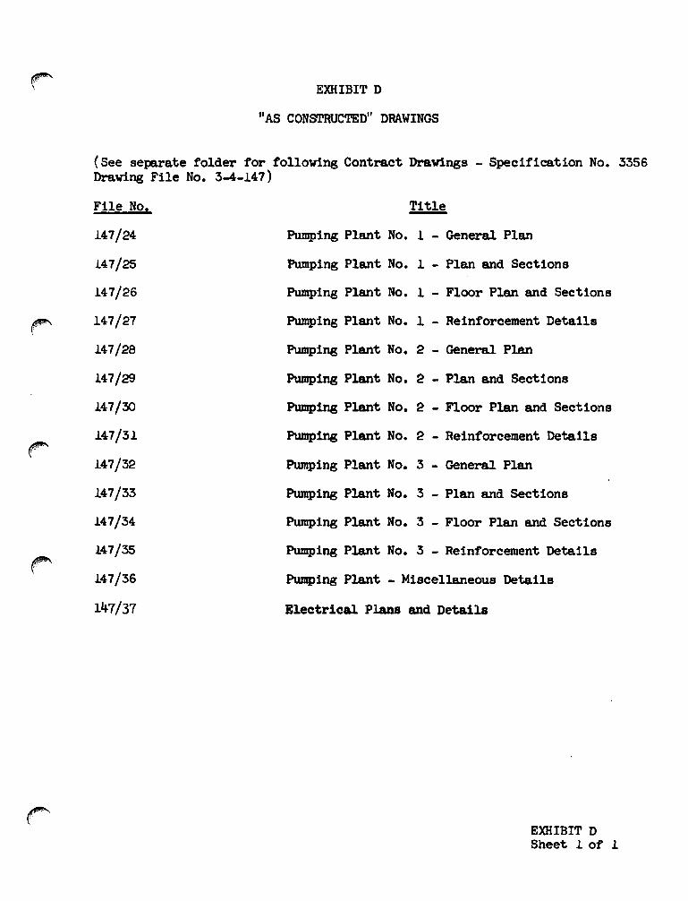
r
EXHIBIT D
"AS CONSTRUCTED" DRAWINGS
(See separate folder for following Contract Drawings - Specification No. 3356Drawing File No. 3-4-147)
File No. Title
147/24 Pumping Plant No. 1 - General Plan
147/25 Pumping Plant No. 1 - Plan and Sections
147/26 Pumping Plant No. 1 - Floor Plan and Sections
147/27 Pumping Plant No. 1 - Reinforcement Details
147/28 Pumping Plant No. 2 - General Plan
147/2!3 Pumping Plant No. 2 - Plan and Sections
147/30 Pumping Plant No. 2 - Floor Plan and Sections
147/31 Pumping Plant No. 2 - Reinforcement Details
147/32 Pumping Plant No. 3 - General Plan
147/33 Pumping Plant No. 3 - Plan and Sections
147/34 Pumping Plant No. 3 - Floor Plan and Sections
147/35 Pumping Plant No. 3 - Reinforcement Details
147/36 Pumping Plant - Miscellaneous Details
147/37 Electrical Plans and Details
EXHIBIT DSheet 1 of 1

EXHIBIT E
Manufacturer I s Data
EXHIBIT E
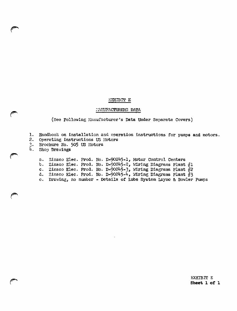
1.2.?....4.
mmIDIT E
;.:>\NUFACTURERS DATA
(See Following Manufacturer's Data Under Separate Covers)
Handbook on installation and operation instructions for pumps and motors.Operating instructions US I·IotorsBrochure No. 505 US r·10torsShop Dra"lings
r' n. Zinseo Elec. Prod. No. D-90245-l, Motor Control Centersb. Zinseo Elee. Prod. No. D-90245-2, vlir1.ng Diagrams Plant IIIc. Zinsco Elec. Prod. No. D-90245-3, Wiring Diagrams Plant #2d. Zinsco Elec. Prod. No. D-90245-4, Wiring Diagrams Plant 1/3c. Drawing, no number - Details of Lube System Layne & Bowler Pumps
~
EXHIBIT ESheet 1 of 1
!·lOm':ON SLOUGH MA.NUAL
EXHIBIT F
PHCYl'OGRA.PllIC PRIm'S OF STRUCTURES
EXHIBIT F
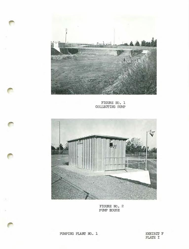
FIGURE NO.1COrn:CJrING SU/1P
FIGURE NO.2PU!1P HOUSE
PU!1PING PIANr 00. 1 EXHIBIT FPLATE I

r'\
pm·P
IN:;
PlJ\!'n'
NO
.1
E',(JIIB
ITF
PLATE
II

FIGURE HO. 5Pffi.W MOTOR
PUMPING PLANr NO. 1
A\1l'OMATICOILER
EXHIBrr FPLATE III

..-• • •...~•
• •
- .. ~~
FIGURE No.6PUMP COIll'ROL SHITCHES
-FIGURE NO. 7
HAnl COI'lrROL Sl.HTCll
PlJ!·!PIHG "?LAhT NO. 1 EXEIilIT FPlATE TV

FLOATI-/ELL
FIGURE !'Ie. '1PU;·IP DISCFJulGE FLEX CONNECTIONS
FIGURE NC. 8PUMP COLUMNS & FLOAT ;JELL

FIGURE ~'O. 10SIPHON BREAKER HOUSIJIG
...... -.~a···..·····.:'VOla ••- ••••••••• '
"" .It ••••••••••••.. .-.- '•••••••••••••••••••••• •• • •••••••••••.... ... . '.... ..-. .- ..... -.- :.. ........-.- ... .. .- - -,••••!._ _._ _·1
FIGURE 110. 11SIPHON BREAKER
PUJ>!PING PlANr NO. 1 EXHIBIT FPlATE VI
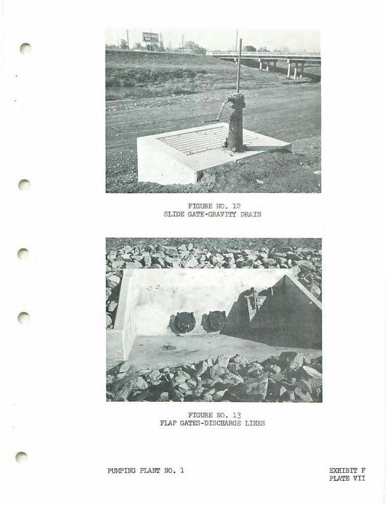
FIGURE HO. 12SLIDE GATE-GRAVrry DRAIlI
FIGURE NO. 13FlAP GATES-DISCHARGE LINES
PUMPING PLANT NO. 1 EXHIBIT FPLATE VII

FIGURE t • 14COJ.FcriliG Str.w 11-26-68
...
FIGURE NO. 15COLLEcrING SU!·l!' 1-21-69
PUJ·1?ING PlAlfIl NO. 2 EXHIBIT FPLATE VIII

FIGURE NO. 16TRASlIRACK
=
FIGURE NO. 17PUl1PING PLA~T
PUNPING PLAN!' NO. 2 EXHIBIT FPlATE IX

FIGURE NO. 18TRASH RACK
FIGURE NO. 19DISCHARGE COLUl·fil
PUHPING PLA!>T NO. 2 EXHIBIT FFlATE X
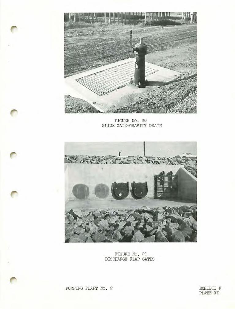
FIGURE ~;O. 20SLIDE GATE-GRAVITY DR4IN
FIGURE NO. 21DISCHARGE FlAP GATES
PUMPING PLA~1r NO. 2 EXHIBIT FPLATE XI
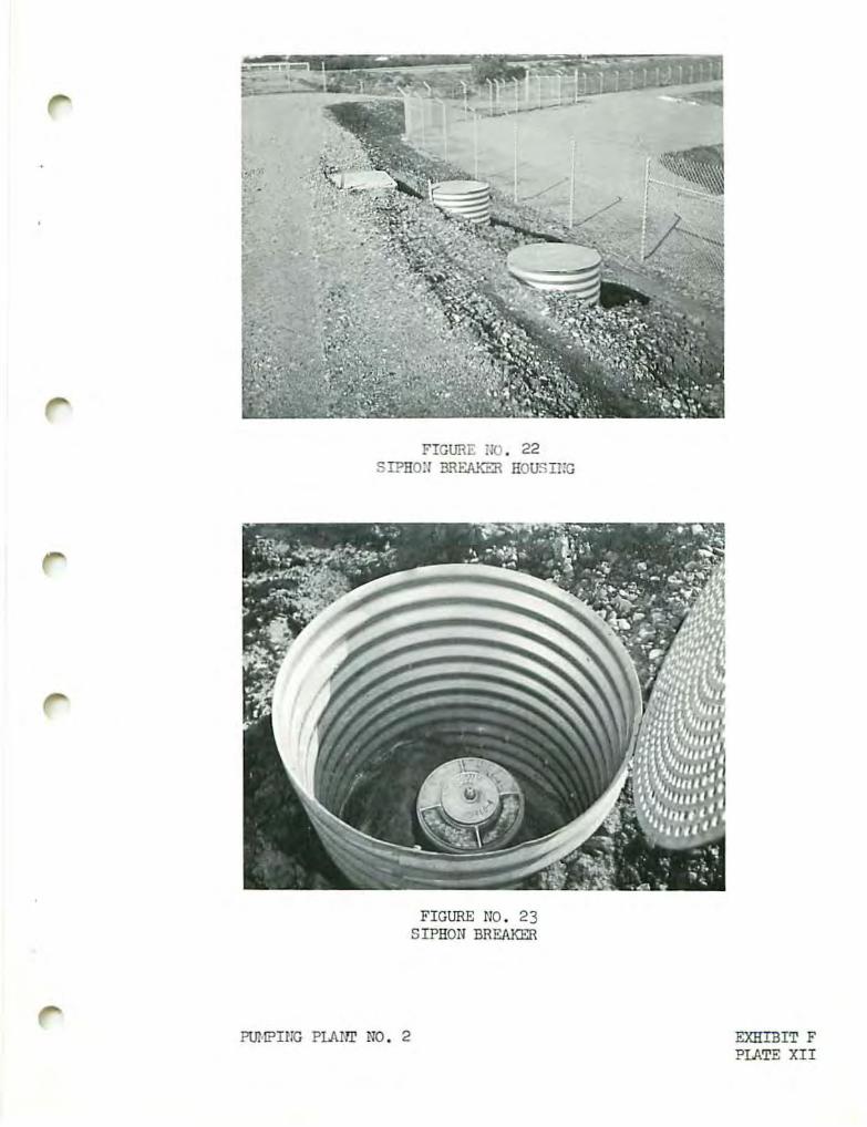
FIGURE iJO. 22SIPHOH B.'qEAKER HOUSIi:G
FIGURE NO. 23SIPHON BREAKER
PUH?ING PlAIn' NO. 2 EXHIBIT FPLATE XII
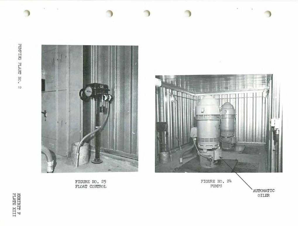
Pln·1PIM:i
PlA
ilr110.
2
••
EX
HIB
ITF
PIM
EX
III

~
I-
'",
,N
fj-
'/::1
@~U
>
'"15;';l~
.11"~:1:
11---
--
-.
-.
.-,.
I.
.<!JliJ
1~•
•
I
1'I
()•
••
~
Im
II
.•
••
-
If'
PU
MP
ING
PlA
UT
NO
.2
EX
HIB
ITF
PLATE
XIV

FIGURE NO. 28TRANSFORJ.lER
PUi.IPING PLAllr NO. 2
EXHIBrr FPLATE Y:Y

•
FIGURE 110. 29COu.EarING SUl·!P
FIGURE NO. 30COu.Earm:; SUl·!P
PUMPING PlAN!' NO. 3 EX!lIllrr FPLATE XVI
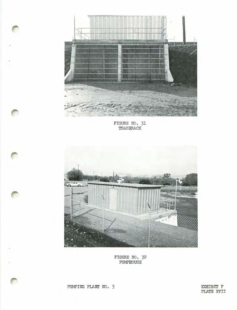
.............,..,............. "" , " " " 1 1 ]'
I '
FIGURE NO. 31TRASHRACK
FIGURE NO. 32PUlolPl!OUSE
PUJ·lPIN:: PlANr NO. 3 EXHIBIT FPlATE XVII

FIGURE NO. 33SLIDE GATE-GRAVITY DRAIN
FIGURE NO. 34FLAP GATES-DISCHARGE LINES
GRAVITYDRAIN
PU!·lPING PLANI NO. 3 EXHIBIT FPLATE XVIII
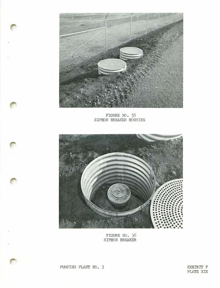
FIGURE NO. 35SIPHON BREAKER HOUSIIlG
........•••••••.... ......... ... .. "...........: ......... .. ..... -...... .. .... ,.......................... .. ..-. - .... : ..... . .................. ...... : ........ ...... ..~ '.- , ...- -...- ....- _..
FIGURE 110. 36SIPHON BREAKER
PlJl·lPING PLAJ:T NO. 3 EXllIBIT FPlATE XIX

FIGURE NO. 38PUNP FWAT CONTROL
FIGURE NO. 37PUMPS
AuroJ-lATICOILER
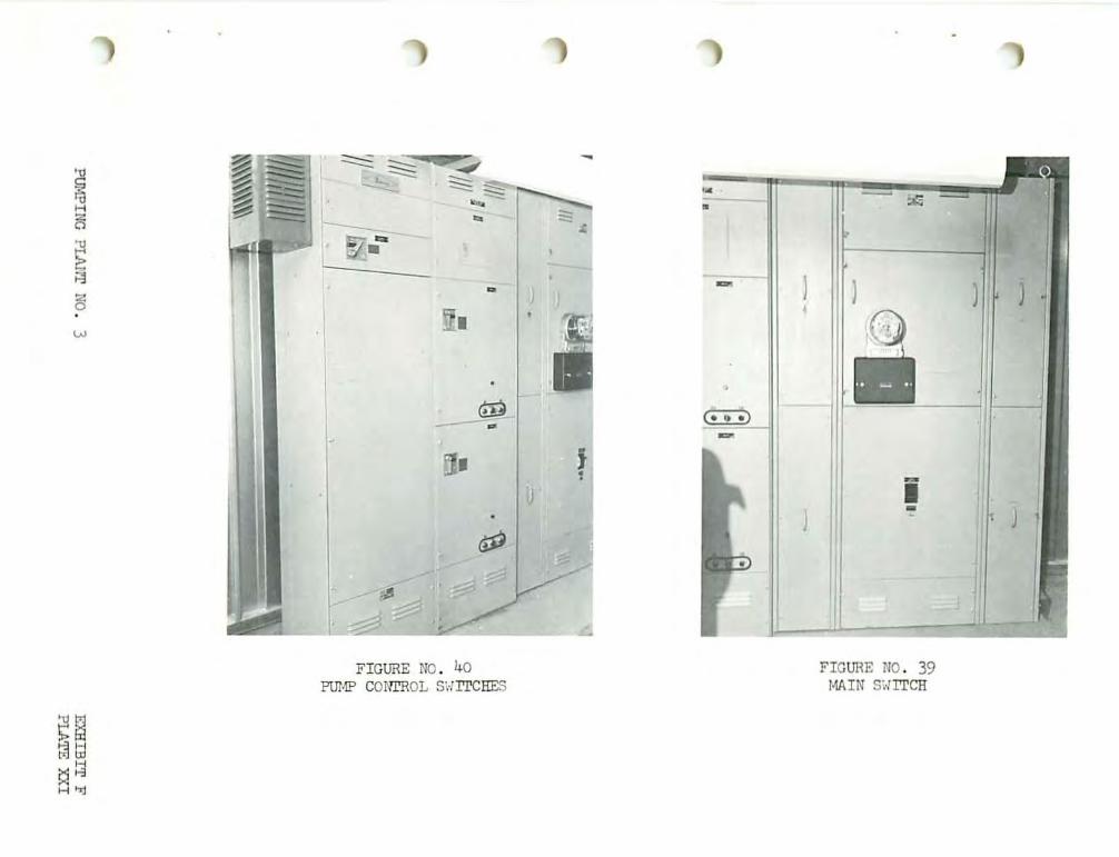
,11/
.....-
1//,••
.~\
.~
~
III•
•51~',-
·iiiit,.,,.~
t!§
"0
0H
U..
IIeIi:
--
P\Ji·iPINC
?LI\rlT
NO
.3
EX
HIB
ITF
PLATE
XX
I

FIGURE NO. I~l
TRP.58RACKE~TRANCE TO SUl·lP
FIGURE NO. 1'2PmlP DISCHARGE COWl·iNS
PUJ.lPING Ph4I~ NO. 3 EXHIBIT FPlATE XXII
tJ1f'"~.. ,
EXHIBIT G
Letter of Acceptance by
state Reclamation Board
EXHIBIT G
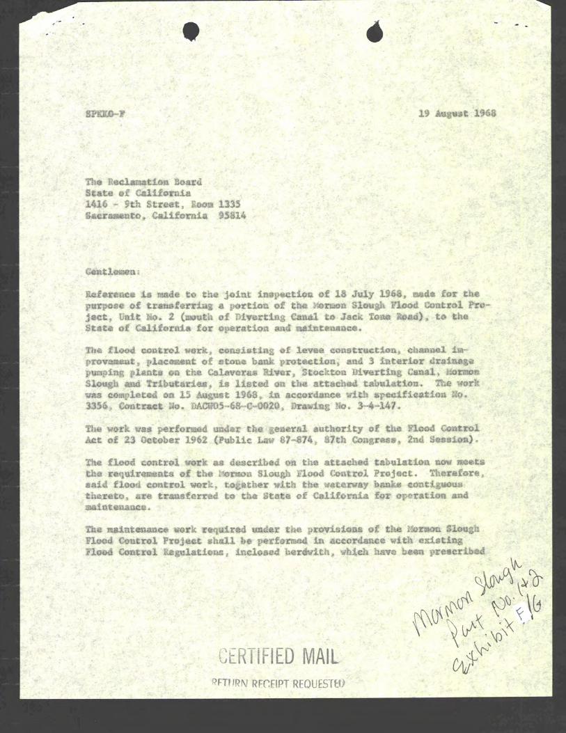


co
py
The Reclamation Board
state of california
co
py
OCT 21 19684130.50.102
"..,r
District EngineerCorps of EngineersU. S. Arasy650 capitol MallSacramento, california 95814
Dear Sir:
Reference is made to your letter of August 19, 1968 concerningtransfer to the State of california of the Mormon Slough Flood ControlProject, Unit No. 2 (mouth of Diverting canal to Jack Tone Road) for maintenance and operation.
This work was constructed in accordance with Specification No.3356, Contract No. DACW05-68-c-0020, Drawing No. 3-4-147.
The Reclamation Board, at its meeting of September 6, 1968,formally accepted the above referred to work for operation and maintenance.
Sincerely yours,
/s/ A. E. McCOLLAMA. E. McCOLLAMChief Engineer and
GeDeral Manager
EXHIBIT G

".~. .-/
EXHIBIT H
Mechanical - Electrical Equipment
Lubrication Schedule
EXHIBIT H
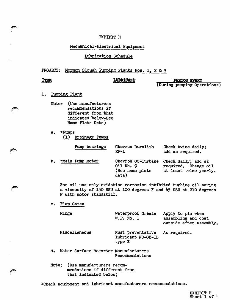
EXHIBIT H
Mechanical-Electrical Equipment
Lubrication Schedule
PROJECT: Mormon Slough Pumping Plants Nos. 1, 2 & 3
1. Pumping Plant
Note: (Use manufacturersrecommendations ifdifferent from thatindicated belOW-SeeName Plate Data)
PERIOD EVBRY(During pumping Operations)
a. *Pumps{l) Drainage Pumps
Pump bearings
b. '*Main Pump Motor
Chevron DuralithEP-l
Chevron OC-TurbineOil No. 9(See name platedata)
Check twice daily;add as required.
Check daily; add asrequired. Change oilat least twice yearly.
For oil use only oxidation corrosion inhibited turbine oil havinga viscosity of 150 SSU at 100 degrees F and 45 SSU at 210 degreesF with motor standstill.
c. Flap Gates
Hinge
Miscellaneous
Waterproof GreaseW.P. No. 1
Rust preventativelubricant NO-OX-IDtype E
Apply to pin whenassembling and coatoutside after assembly.
As required.
-r'
d. Water Surface Recorder Manua:t'acturersRecommendations
Note: (Use manufacturers recommendations if different fromthat indicated below)
*Check equipment and lubricant manufacturers recommendations.
EXHIBIT HSheet 1 of 4
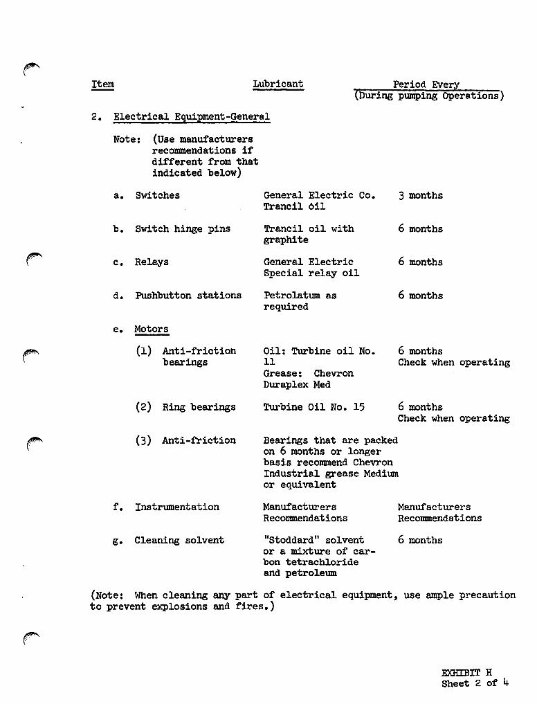
Period Every(During pumping Operations)
LubricantItem
2. Electrical Equipment-General
Note: (Use manufacturersrecommendations ifdifferent from thatindicated below)
a. Switches General Electric Co. 3 monthsTrancil 6il
b. Switch hinge pins Trancil oil with 6 monthsgraphite
c. Relays General Electric 6 monthsSpecial relay oil
d. Pushbutton stations Petrolat\Dll as 6 monthsrequired
e. Motors
(1) Anti-frictionbearings
Oil: Turbine oil No.11Grease: ChevronDuraplex Med
6 monthsCheck when operating
(2) Ring bearings Turbine Oil No. 15 6 monthsCheck when operating
(3) Anti-friction Bearings that are packedon 6 months or longerbasis recommend ChevronIndustrial grease Medi\Dllor equivalent
f. Instrumentation ManufacturersRecommendations
ManufacturersRecommendations
6 monthsg. Cleaning solvent "Stoddard" solventor a mixture of carbon tetrach10rideand petro1e\Dll
(Note: When c1eaning any part of electrical equipment, use ample precautionto prevent explosions and fires.)
EXHIBIT HSheet 2 of 4

3. General Notes
a. The above lubrication schedule is prepared as a general guide. Itshould be revised and expanded as experience is gained in the operation ofthe particular units of equipment. Refer to catalog data and manualssupplied with equipment for location of lubrication points and pertinentdata.
b. When contracting for lubricants recommend using U. S. GovernmentMilitary, Federal and AGMA specifications when available. Any reputablesupplier of suitable lubricants can advise as to what specificationscorresponds to branded products listed or recommended for a particularapplication, or if none, approved brands of other manufacturer. The brandnames indicated are to facilitate identification only as to type and gradeof lubricant recommended for a particular application, and is not intendedto limit the procurement of lubricants to any one particular supplier.
c. Manufacture of lubricants specified above.
(1)
(2)
(3)
(4)
(5)
(6)
(7)
UNO - Union Oil Co.
NO-C)X-ID - Dearborn Chemical Co.
Chevron - Standard Oil Co. of California
Tranoil - General Electric Co.Special oil for electrical equipment.
RPM - Standard Oil Co. of California
"Stop-Rust" - The Delta Mfg. Co., Milwaukee, Wisconsin
Stoddard Solvent - Described in U. S. Bureau of Standardsas "Commercial Standard 05-3-28"
d. Electrical equipment shall be lubricated only when recommendedby the equipment manufacturers or in accordance with best acceptedpractice for the service. Where lubrication is required, lubricateadequately but sparingly, wiping off any excess lubricant, as oilysurfaces collect dust and may result in an arc between live parts.
e. The above schedule is provided as a general guide in the absenceof specific recommendations from the manufacturer of the respectiveitems of equipment. Use only the best grades of lubricants and of thetype and in accordance with the manufacturer' s recommendation whereavailable. When in doubt, consult with one of the manufacturers of lubricants suitable for the service.
EXHIBIT HSheet 3 of 4

f. Daily checks pertain to actual operating periods. Check shouldalso be made periodically during any extended periods when equipment isnot operated.
g. Lubricant storage and handling. Lubricant reserves should be keptin closed containers and stored in a clean, well-ventilated, dry place.Lubricants shall be kept free from grit or other foreign material, at alltimes. When applying lubricant with a pressure grease gun, the fittingsshall be wiped clean just before and just after the application.
EXHIBIT HSheet 4 of 4

EXHIBIT I
Mechanical-Electrical Equipment
Inspection Check List
EXHIBIT I
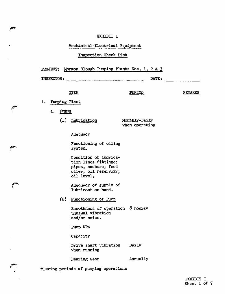
EXHIBIT I
Mechanical-Electrical Equip!ent
Inspection Check List
PROJECT: Mormon Slough Pumping Plants Nos. 1, 2 & 3
INSPECTOR: _ DATE: _
ITEM-1. Pumping Plant
a. Pumps
(1) Lubrication
Adequacy
Functioning of oilingsystem..
Condition of lubrication lines fittings;pipes, anchors; feedoiler; oil reservoir;oil level.
r"" Adequacy of supply oflubricant on hand.
PERIOD
Monthly-Dailywhen operating
REr4ARKS
(2) Functioning of Pump
Smoothness of operation 8 hours*unusual vibrationand/or noise.
Pump RPM
Capacity
Drive shaft vibrationwhen running
Bearing wear
*During periods of pumping operations
Daily
Annually
EXHJJ3IT ISheet 1 of 7

~.
ITEM PERIOD REMARKS
(3) Adjustment Yearly
Check Adjustment(See Pump Manual)
Miscellaneous
(4) Condition of Pump Yearly
BearingsDrive shaftDrive shaft connections
r Grease packing rings
(5) Pu;m.P anchorage Week1y*
(6) Debris in pumping Daily*pit around pumpsuction
r"(7) Discharge line 6 months
Discharge pipesPipe couplingsFlap gatesAir reliefs
(8) Condition of metal work 6 months
r (9) Miscellaneous
b. Pump Motors
(1) Lubrication
Adequacy Daily*
Bearing temp., noise, Daily*vibration.
Functioning of bearing 8 hours*
nubricant piping,fittings 8 hours*
Note signs of oil leak-age at any point 8 hours*
r-*During periods of pumping operations.
EXHIBIT ISheet 2 of 7

~
IT»! PERIOD REMARKS-(2) Motor Operation
Note any indication of Daily*'excessive temperaturerise W1der load
Abnormal vibration Dai1y*and/or noise
Check function of Dai1y*motor controls
Note any failure of Dai1y*motor to pull inthroughout the loadrange
Inspect for moisture 3 monthsinside the motor housing
MOtor base anchorage 3 months
(3) Drive shaft & coupling
Inspect for fW1ctioning Monthlyand condition
(4) Note accumulations of Dai1y*oil on or aroW1d themotor
(5) Metal Work
Note rust spots wear & 6 monthscondition of paints
(6) Spare Parts
Adequacy of supply 6 months
c. Floatwells and house
Floatwells Month
House and appurtenances Month
Pump controller Month
*During periods of pumping operations.
EXHIBIT ISheet 3 of 7

,..ITEM PERIOD REMARKS-
d. Trashracks
Condition of metal work Annually
Anchorage Annually
Note debris in rack & pool Dai1y*that should be removed
e. Flap Gates
Condition of sealS 6 months
Condition of metal work 6 months
Functioning during Dailyoperation
Note any indication of Dai1y*leakage when closed
r-- Miscellaneous
f. Pump Discharge Pipes
Air release pipes 6 months
Miscellaneous 6 months
r 2. Electrical Systems
a. Main Switch Board
(1) Inspect all equipment andnote need for cleaning Monthly
(2) Check switches and con-trols to insure that they Montblyare mechanicallyoperable
(Note indications of sluggishoperation or sparking)
(3) Report any failure of thecontrols to control the DaUY*
~operation of the unitsfor which they areintended
*During periods of pumping operations.EXHIBIT ISheet 4 of 7
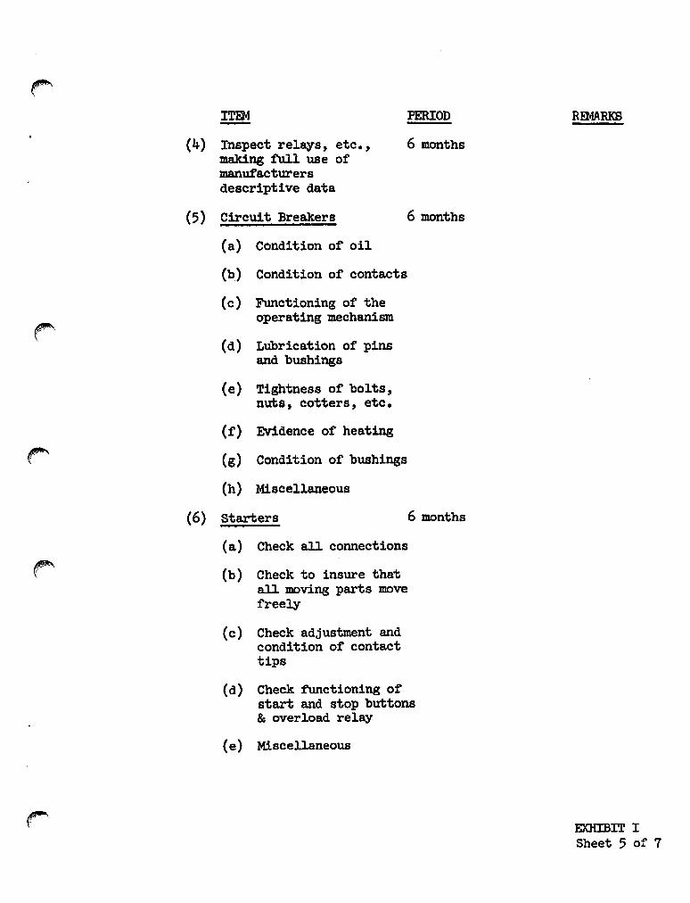
r-ITEM PERIOD Ra.mRKS-
(4) Inspect relays, etc., 6 monthsmaking full use ofmanufacturersdescriptive data
(5) Circuit Breakers 6 months
(a) Condition of oil
(b) Condition of contacts
(c) Functioning of theoperating mechanism
(d) Lubrication of pinsand bushings
(e) Tightness of bolts,nuts, cotters, etc.
(f) Evidence of heating
(g) Condition of bushings
(h) Miscellaneous
(6) starters 6 months
(a) Check all connections
r" (b) Check to insure thatall moving parts movefreely
(c) Check adjustment andcondition of contacttips
(d) Check functioning ofstart and stop buttons& overload relay
(e) Miscellaneous
EXHIBIT ISheet 5 of 7

,...ITEM PERIOD REMARKS
(7) Contactors 6 Months
(a) Check for proper func-tioning, includingopening and closingoperation
(b) Inspect contacts
(c) Check adjustment ofcontact gap
(d) Check contact pressurer'"
(e) Miscellaneous
b. Miscellaneous 6 Months
(1) Lighting System
(a) Check light fixtures
r"and controls forproper functioning
(b) Check adjustment Every monthof floodlight
(c) Inspect circuit Every monthbreakers
r-- (d) Check supply of Every monthfuses and lightbulbs on hand
(2) Pu!P Motor Controls
Check the entire electricsystem provided for YearJ.yoperating the mainpmaping units
(3) Power Supply
Generally inspect thePower Co.'s transmission MontbJ.yline installations in thevicinity of the pumping
r~l plant
EXHIBIT ISheet 6 of 7
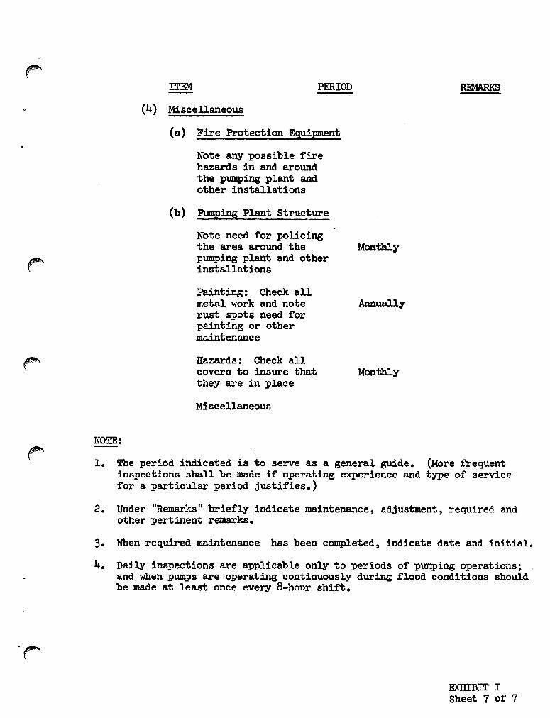
PERIODITEM
(4) Miscellaneous
(a) Fire Protection Equipment
Note any possible firehazards in and arolUldthe pumping plant andother installations
(b) Pumping Plant structure
NOTE:
Note need for policingthe area arolUld thepumping plant and otherinstallations
Painting: Check allmetal work and noterust spots need forpainting or othermaintenance
Hazards: Check allcovers to insure thatthey are in place
Miscellaneous
Monthly
Annually
Monthly
1. The period indicated is to serve as a general guide. (More frequentinspections shall be made if operating experience and type of servicefor a Particular period justifies.)
2. Under "Remarks" briefly indicate maintenance, adjustment, required andother pertinent remarks.
3. When required maintenance has been completed, indicate date and initial.
4. Daily inspections are applicable only to periods of pumping operations;and when pumps are operating continuously during t~ood conditions shouldbe made at least once every a-hour shift.
EXHIBIT ISheet 7 of 7

EXHIBIT J
Sample Log Form, Recording and
Reporting Operation of Pumping
Plant During Flood Period
EXHIBIT J

SAMPLE WG FORM FOR RECORDING AND REPORTINGOPERATION OF PUMPING PIANT DURING EXTREME EMERGENCY FLOOD CONDITIONS
DATE: -------------- PLANT: ----------- SUPERINTENDENT: _
start stopWater Level Water Level Remarks*'
Pump No. Time Sumo River Time Sump River
*Brief note under Remarks with reference to more detailed comments on an attached sbeet.Service interruptions, if any: abnormal high temperature of motor; abnormal noise;improper functioning of automatic controls and appurtenances, including time durationand cause. This form should be ~sed only when operators are on duty continuously.

SAMPLE LOG FORM FOR RBX>RDDfG AND REPORTINGOPERATION OF PUMPING PLANT DURING PERIODIC VISITS
DATE: PlANT:----------- ----------- SUPERINTENDENT: _
Pump Operating Water LevelPump No. Time (yes - no) Sump River Remarks*'
*Brief note under Remarks with reference to more detailed comments on attached sheetdescribing any unusual or abnormal conditions observed.
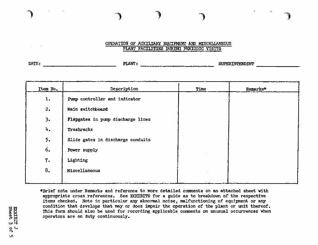
)
OPERATION OF AUXILIARY EQUIPMENT AND MISCELLANEOUSPlANT FACILITIES DURING PERIODIC VISITS
DATE: ------------- PLANT: ------------- SUPERINTENDENT _
Item No. Description Time Remarks*
1. Pump controller and indicator
2. Main switchbOsrCl
3. Flapgates in pump discharge lines
4. Trashracks
5. Slide gates in discharge conduits
6. Power supply
7. Lighting
8. Miscellaneous
*Brief note under Remarks and reference to more detailed comments on an attached sheet withappropriate cross references. See EXHIBITS for a guide as to breakdown o~ the respectiveitems checked. Note in particular any abnormal noise, malfunctioning of equipment or anycondition that develops that mayor does impair the operation of the plant or unit thereof.This form shouLd also be used for recording applicable comments on unusual occurrences whenoperators are on duty continuously.

)
(Attachment for Sheet 1 of EXHIBIT J)OPERATION OF PUMPING PLANT DURING EXTREME EMERGENCY FLOOD CONDITIONS
DATE: ----------- PIANT: ---------- SUPERINTENDENT: _
PU!1IP No. Time Remarks (Reference Sheet 1 of Exhibit J)
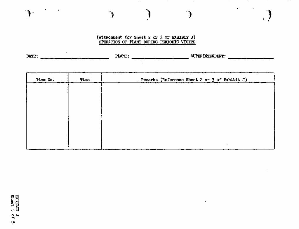
) ,
1 ) ') 1t Y'
(Attachment for Sheet 2 or 3 of EXHIBrT J)OPERATION OF PlANT DURING PERIODIC VISITS
DATE: _ PLANT: SUPERINTENDENT:---------- --------
Item No. Time Remarks (Reference Sheet 2 or 3 of Exhibit J)

I' I--- I I--- l .'._.....
, By Act of California Legislature" Chapter 1438 of the Statutes of 1963(California,Water Code Section 12657), the Reclamation Board is authorized togive assurances satisfactory to the Secretary of the Army that the localcooperation required by Section 3 of the Act of Congress" approved December 22,1944 (Public Law 534" 78th Congress, Second Session)" and Section 2 of the Actof Congress" approved August 18, 1941 (Public Law 228" 77th Congress, .FirstSession)" will be fUrnished by the State in connection with the M:lrmon SloughProject.
Section 3 of Public Law 534 and Section 2 of Public Law 228 provide thatthe authorization for any flood control project ~equiring local cooperationshall expire five years from the date on which local interests are notifiedin writing by the lfar Department of the requirements of local cooperation" unless said interests shall" within said time" furnish assurances satisfactory "to the Secretary of War that the required coopera.tion will be, furnished. T'neReclamation Board was notified by the District Engineer, ,Sacramento District,,'by letter dated 25 March 1966 of the requirements of local cooperation.
, ,
By Resolution adopted by the State ReClamation Board at its meeting of ','7 July 1966, the General Manager of the Reclamation Board was authorized tofurnish the required assurances to the Corps of Engineers in accordance 'v.lththe requirements in House Document No. 576 as ,set forth above in accordancewith ,this authorization,. '
Mr. A. E. McCollam" General.l'o1a.nager of the Reclamation Board, by lett~r;
dated 7 July 1966" has furnished the required assurances" A review of theassurances discloses that they comply ~dth the requirements of the authorizing I
act and with the recommendations of the Chief of Engineers.
In view of the foregoing facts" it is concluded that: (1) the ReclamationBpard has been authorized by the Legislature to give the assurances; (2) the
(,. Legislature has provided adequate funds and has authorized the project; and(3) the Reclamation·Board has" in accordance with Public Law 534" furnishedthe assurances within five years of the date of notification by the Secretaryof the Army of the requirements of local cooperation. The assurances, asgiven" are therefore considered legally and financially adequate.
#/)" /"1 c//4.;y~/ 1""'.4~ ,,~,. _;/ , ;I "$b:'-"--'-'-0e. " ~e,-..z--._,,-'h /~ .",v ~ -~ ... .. -"
H.'BOYD JjD»ISON, Attorney, Real Estate DiVisionu. S. Army Engineer District, SacramentoCorps of Engineers
.~.

.'
I .--
ME:~~RANDUM OPINION OF ASSURANCES
M:>rmon Slough Project" Calaveras River, California
Public Law 87-874, approved 23 October 1962" authorized a project forflood protection on M:>rmon Slough, Calaveras River, California, substantiallyin accordance·with the recommendations of the Chief of Engineers in House .Document numbered 576, 87th Congress, Second Session.
The Chief of Engineers, in said House Document numbered 576, recommendedIconstruction of the project at an estimated total cost of' $3,460,000 of which,$1,,960,000 would be the federal cost of construction, and $1,500,000 non-federalcosts for lands., easements, rights':'c)f-\iay alld relocations, provided that priorto construction local interests sive assurances satisfactory to the Secretaryof the Army and that they would" without cost to the United States:
a. furnish all lands, easements, and rights-of-way" including spoildisposal areas, necessary f'or constr-..tction of the works;
b. accomplish all relocations and alterations of' roads, streets,buildings, pipelines" utilities" bridges, and other structures (except railroad facilities) made necessary by the construction work;
, - '-~
~)
c. hold and· save the United States free from damages due to theconstruction works;
d. maintain and operate all the works after completion" includingthe lower Calaveras River, in accordance with regulations prescribed by theSecretary of the Army; and
e. prescribe and enforce regulations designed to prevent encroachment of any type that would impair the flood control effectivenes~ of the works •
•j
By Act of the California legislature, Chapter 915 of the Statutes of 1963(California Water Code Section 12648.6), the 2-brmon Slough Channel ImprovementProject was adopted and authorized substantially in accordance. wi°tih the recommendations of the Chief of Engineers in House Document No. 576" 87th Congress.,at the estimated State cost of $2,260,,000.
The following items have been included in Budget Acts enacted by theCalifornia Legislature:
a. Item 396 (f)., Chapter 2 of 1964 Budget Act (authorized $65,000)
b. Item 308 (e)., Chapter 757 of 1965 Budget Act (authorized $1,,230,395)
c. Item 353 (e)., Chapter 2 of 1966 Budget Act (authorized $1,999,817)
\

" ,
:orATE Of CAlIFCRNIA-RESOURCES AGENCY
rHE RECLAlv\ATION BOARDRESOURCES IlUILDING, 1416 9TH STREET 0 SACRAMENTO 95814
STANLEY W. KRONICK, Pr..ldonlJ. J. MADIGAN. Vic. Pra.ldan'WALLACE McCORMACK. So.rolarrGEORGE W. NICKEL. JR.HAROLD J. O'BANIONH. TERRILL SARTAINDONALD L. WEILER
COL A. E. ~COLLAM. Gonora' Mana".,
District EngineerSacramento DistrictU. S. Corps of Engineers650 Capitol Mall ..Sacramento, California
July 7, 1966
R.'", tOI
, , ,./' '/" ..~_/."--.. "- .l( <" ,)
EDMUND G:. &ROWN, Gov.rnor
,,; .I,'
Dear Sir:
. Reference is made to the authorized Mormon SloughCalaveras River Project, California, and to your letter of25 March 1966 requesting that the State Reclamation Board furnish you the assurances of local cooperation as required byFederal law. .
This will inform you that the Reclamation Board, atits meeting'on July 7, authorized the General Manager to furnishyou with the required assurances for the project. The ReclamationBoard, for the State of California, under the authoritygranted~t under Chapte~ 1438 of the Statutes of 1963, herebyfurnishes the following assurances to you with respect to theMormon Slough~Calaveras River Project.
The Board will, without cost to the United States:
a) Furnish all lands, easements and rights of way,including spoil-disposal areas, necessary for constructionof the works;
b) Accomplish all relocations and alterations ofroads, streets, buildings, pipelines, utilities, bridgesand other structures, (except railroad facilities) madenecessary by the construction work;
c) Hold and save the United States free fromdamages due to the construction works;
d) Maintain and operate all thl! works aftercompletion, including the lower Calaveras River, inaccordance with regulations prescribed by the Secretaryof the Army: .
' .•• -.....- .... ~ . -,' I" ' ....-.- •.-. -~ " ,,
"

•• : ,I .•
u. ' s. Corps ot Engineers ,: . -2- July 7, 1966
e) Prescribe and enforce regulations designedto prevent encroachment of any type that would impairthe flood-control effectiveness of the work.
Attached to this letter you will find a certified copyof the Board's resolution which authorizes the General Managerto to furnish to you the required assurances.
,1
~ ~,.j
ENC.
. .:
,J' •• '
.; ~ ...
, ,• _ ..... ,.. I
Very truly yours,
tf-~?J1 Q C.:-C{:~
A. E. McCOLLAMGeneral Manager
. c." ~
.. \ ......-.
..... ~. -.. ", ..'..-".~ -"-
, .. . . . ~ .,
\ '. "., .
" '
.,"1.
'/
- ." .....
.. ,. ,.
, ,','" .~. ._' o,.4O\J ••• '_... ~ ... , .• '_ •
. . • I • • ' •
.. , • - •••••• ',. -0 .', ' .. ;.
:-":. ,;,:. ,: ••• : • ,I
.,.... ..'1 \..... ::

.!
.'...I'
"~. ,
-
,It..., .. ,........-"'.
RESOLUTION ADOPTED BY THE STATE RECLN'~TION BOARDAT ITS MEETING OF JULY 7, 1966
WHEREAS, the Mormon Slough, Calaveras River Project wasI
authorized by the Flood Control Act of 1962 substantially in a~cora
ance with the recommendations of the Chief of Engineers as outlinedI
in House Document No. 576, 87th Congress, Second Session; and I
WdEREAS, House Document No" 576, the authorizing docu."Uent,'I
requires that prior to construction local interests give assurancesI
satisfactory to the Secretary of the Army that they will without
cost to the United States:
a) Furnish all lands; easements and rights of way,
including spoil-disposal areas, necessary for construction
of the works;
b) Accomplish all relocations and alterations of
roads, streets, buildings, pipelines, utilities, bridges
and other structures (except railroad facilities) made
necessary by the construction work;
c) Hold and save the United States free from
damages due to the construction works;
d) Maintain and operate all the works after
completion, inclUding the lower Calaveras River, in
accordance with regulations prescribed by the Secretary
of the Army;
e) Prescribe and enforce regulations designed to
prevent encroachment of any type that would impair the
flood-control effectiveness of the work; and
WrlEREAS, the Legislature of the State of California auth
orized the Mormon Slough Channel Improvement Project on the Calaveras
River substantially in accordance with the recommendations contained

, ,
p~oject'and will without cost'to the United. States:
~.' "(.
-2-I
WHEREAS, the Legislature'of'the State of California
authorized the Reclamation Board or the State of California to give
the required assurances to the Corps of Engineers:under Chapter 1438"
of the Statutes of 1963:
NOW, THEREFORE BE 'IT RESOLVED that the Reclamation Boardi
of the State of California shall furnish the necessary assurances, . • !
to the Corps of Engineers on the Mormon ,Slough Calaveras River, I·· ,I
.~'. .. ..J ~ J. .... ,_, . "
--", a) Furnish all lands, easements and rights of way,
including spoil-disposal areas,.· necessary for construc-
... 'tion'of the works: .....~ '-
b) Accomplish all relocations and alterations of
roads, "s;tree·t~,· bui·ldings·, pipelines, uti,lities, bridges
::"a:rid oth:;;r"'structures" (except.railroad..facil~_tie~) mad.~
'ne'cessaryby the construction work; ,:
c) . Hold and save the United States free from
damages due to the construction works;
d) Maintain and operate all the works after
completion, including the lower Calaveras River, in
'accordance with regulations prescribed by the Secretary
., of the Army:
" e)" Prescribe and enforce regulations designed to
"...\
prevent encroachment of any type that would impair the
'j:: 'frood~controi' effectiveness of~ .thework.i .an¢1 '"
.. ' . ,:•...... BE' IT FURTHER RESOLVED that.'. the General Manager of the
Reclamati~n'Board'of 'the State of California is authorized to.
furnish the required assurances to the Corps of Engineer~ in,.
accordance with the requirements set. forth in Hou~.e Document,:No •. '.' .... , -." - -..... 0,: L.... _ :-. "-. • , - - ..... .:l t::-.- __ ,: ........... ,',", :

,:~.....
STATE OF CALIFORNIA )COUNTY OF SACRAMENTO ) s s •Office of The Reclamation Board )
I, P. H. SERVEN, Chief, Administrative Services ofThe Reclamation Board, do hereby certify that the foregoingis a true and correct copy of a resolution adopted by theReclamation Board. at the meeting of said Board held on July 7,1966.
IN WITNESS WHEREOF, I have hereunto set my hand andaffixed the official seal of The Reclamation Board this 7thday of July, 1966 •
(SEAL)
P. H. SERVENchief, Administrative ServicesThe Reclamation Board
dc