morbark parts and service the solution to your problems ... · pdf filemorbark parts and...
TRANSCRIPT

3.24
Morbark parts and service the solution to your problems. Buying your parts
elsewhere just does not pay.
To keep your equipment performing at its peak use
GENUINE MORBARK PARTS800-255-8839 800-832-5618fax
www.morbark.com
76345-276 • 12-08
4.1
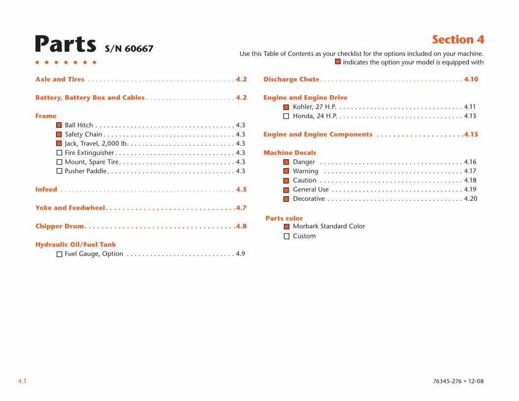
Section 4
Axle and Tires . . . . . . . . . . . . . . . . . . . . . . . . . . . . . . . . . . . . . . 4.2
Battery, Battery Box and Cables . . . . . . . . . . . . . . . . . . . . . . . 4.2 Frame Ball Hitch . . . . . . . . . . . . . . . . . . . . . . . . . . . . . . . . . . . . 4.3 Safety Chain . . . . . . . . . . . . . . . . . . . . . . . . . . . . . . . . . . 4.3 Jack, Travel, 2,000 lb. . . . . . . . . . . . . . . . . . . . . . . . . . . . 4.3 Fire Extinguisher . . . . . . . . . . . . . . . . . . . . . . . . . . . . . . . 4.3 Mount, Spare Tire. . . . . . . . . . . . . . . . . . . . . . . . . . . . . . 4.3 Pusher Paddle . . . . . . . . . . . . . . . . . . . . . . . . . . . . . . . . . 4.3 Infeed . . . . . . . . . . . . . . . . . . . . . . . . . . . . . . . . . . . . . . . . . . . . . 4.5 Yoke and Feedwheel. . . . . . . . . . . . . . . . . . . . . . . . . . . . . . .4.7 Chipper Drum. . . . . . . . . . . . . . . . . . . . . . . . . . . . . . . . . . . .4.8 Hydraulic Oil/Fuel Tank Fuel Gauge, Option . . . . . . . . . . . . . . . . . . . . . . . . . . . . 4.9
Parts S/N 60667
Discharge Chute . . . . . . . . . . . . . . . . . . . . . . . . . . . . . . . . . . . . . 4.10
Engine and Engine Drive Kohler, 27 H.P. . . . . . . . . . . . . . . . . . . . . . . . . . . . . . . . . 4.11 Honda, 24 H.P. . . . . . . . . . . . . . . . . . . . . . . . . . . . . . . . . 4.13 Engine and Engine Components . . . . . . . . . . . . . . . . . . . . .4.15
Machine Decals Danger . . . . . . . . . . . . . . . . . . . . . . . . . . . . . . . . . . . . . 4.16 Warning . . . . . . . . . . . . . . . . . . . . . . . . . . . . . . . . . . . . 4.17 Caution . . . . . . . . . . . . . . . . . . . . . . . . . . . . . . . . . . . . . 4.18 General Use . . . . . . . . . . . . . . . . . . . . . . . . . . . . . . . . . . 4.19 Decorative . . . . . . . . . . . . . . . . . . . . . . . . . . . . . . . . . . . 4.20
Parts color Morbark Standard Color
Custom
Use this Table of Contents as your checklist for the options included on your machine.indicates the option your model is equipped with
76345-276 • 12-08
4.2
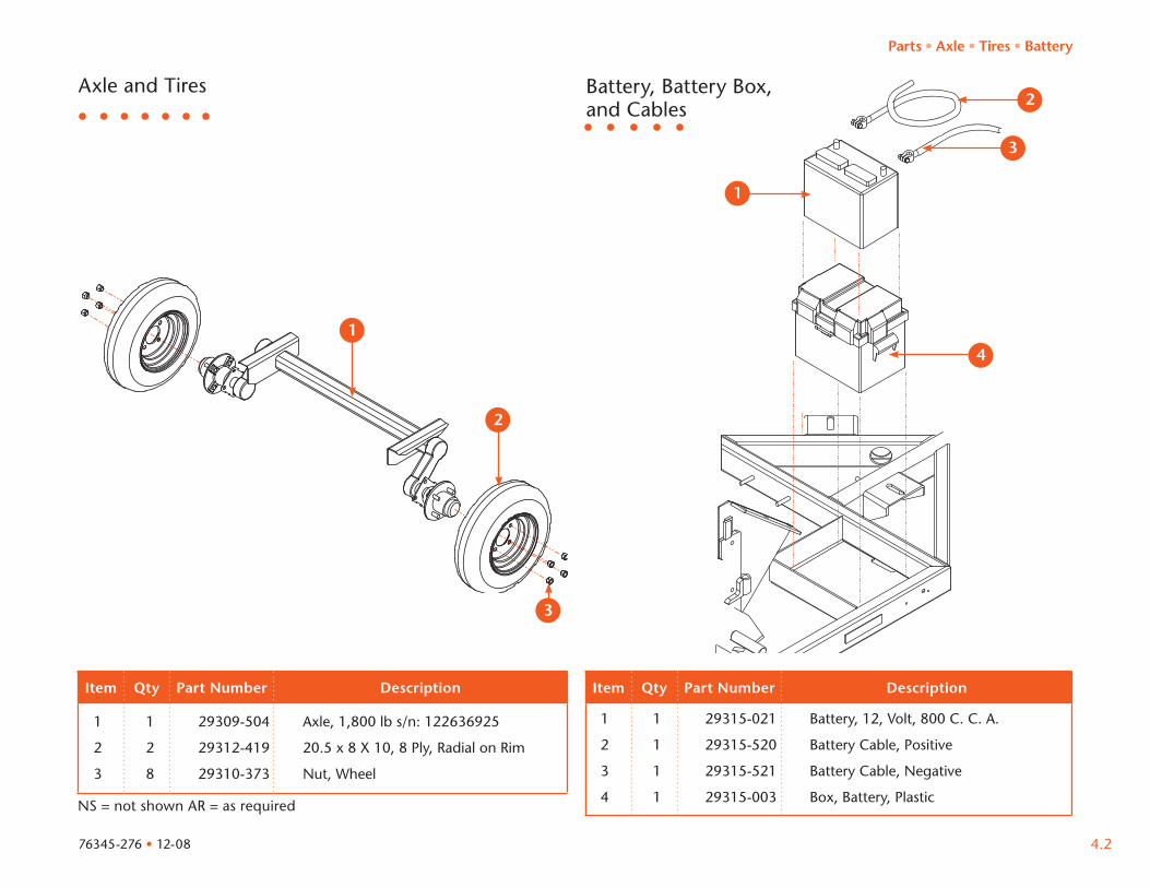
Axle and Tires
Item Qty Part Number Description
Battery, Battery Box, and Cables
Item Qty Part Number Description
NS = not shown AR = as required
1 1 29309-504 Axle, 1,800 lb s/n: 122636925
2 2 29312-419 20.5 x 8 X 10, 8 Ply, Radial on Rim
3 8 29310-373 Nut, Wheel
1 1 29315-021 Battery, 12, Volt, 800 C. C. A.
2 1 29315-520 Battery Cable, Positive
3 1 29315-521 Battery Cable, Negative
4 1 29315-003 Box, Battery, Plastic
Parts • Axle • Tires • Battery
76345-276 • 12-08
1
2
3
31
34
32
33
4.3
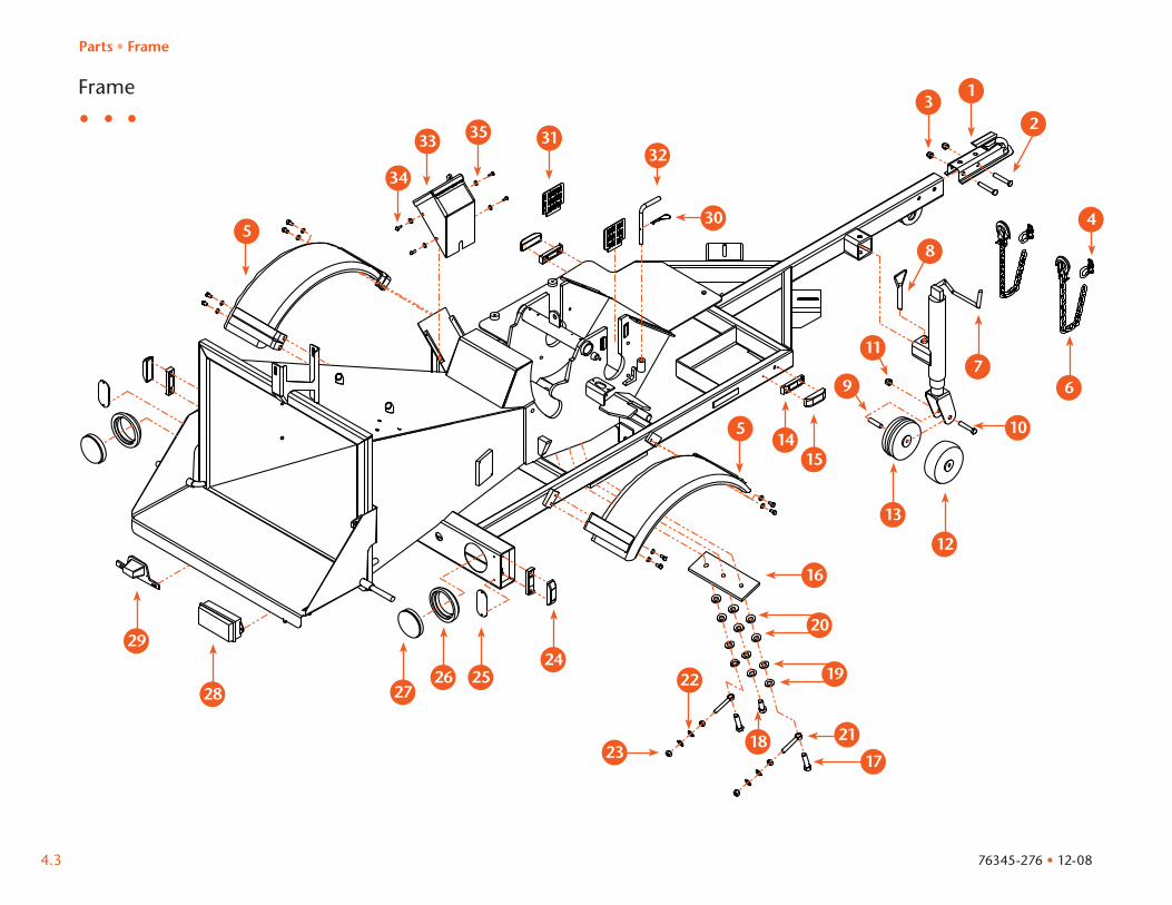
Frame
Parts • Frame
76345-276 • 12-08
4
18
32
17
21
6
12
13
9
11
10
7
8
13
22
1415
30
23
5
34
33 35
5
19
16
2
28
2924
252627
20
31

4.4
Item Qty Part Number Description Item Qty Part Number Description
NS = not shown
1 1 29341-939 Hitch, Ball Assembly, 2”
2 2 21624-261 Bolt, 1/2”-13 x 3”
3 2 21733-305 Nut, Lock, 1/2”-13
4 2 24711-206 Screw Pin, Anchor Shackle, 7/16”
5 2 40201-201 Fenders
6 2 29313-530 Safety Chain with Hook, 44”
7 1 29341-843 Jack, 2000 LB
NS 1 29340-302 Jack, 2000 LB
8 1 29341-846 Pin, Jack
9 1 32111-460 Bushing, Jack
10 1 21625-260 Bolt,, 1/2” - 13 x 2 3/4”
11 1 21733-305 Nut, Lock, 1/2” - 13
12 1 29312-139 Wheel, Steel
13 1 29312-138 Wheel, Plastic
14 4 Light, Marker, Mount, See Schematic
15 2 Light, Marker, Amber, See Schematic
16 1 30087-061 Base, Anvil
17 2 21624-357 Bolt, 5/8”-11 x 2 1/2”
18 1 21624-353 Bolt, 5/8”-11 x 1 1/2”
19 6 21161-046 Washer, Flat, 5/8”
20 6 21161-359 Washer, Flat, 5/8”
21 2 21711-018 Bolt, Eye, 1/2” x 3”
22 4 21161-044 Washer, Flat, 1/2”
23 4 21731-068 Nut, 1/2”-13
24 2 Light, Marker, Red, See Schematic
25 2 29316-301 Reflector, Red
26 2 29316-313 Seal, Tail Light
27 2 Tail Light, Red, See Schematic
28 1 Box, Junction, See Schematic
29 1 Holder, License Plate, See Schematic
30 1 21129-313 Hair Pin, 3/16” x 3 1/4”
31 2 30428-201 Cover, Base, Drum Shaft
32 1 30323-201 Pin, Drum
33 1 40283-455 Autofeed Box
34 4 21624-003 Bolt, 1/4” - 20 x 3/4”
35 4 21161-061 Washer, Flat, 1/4”
NS 1 59501-021 Fire Extinguisher
NS 1 59501-022 Mount, Fire Extinguisher
NS 1 40236-201 Mount, Spare Tire
NS 1 39234-251 Pusher Paddle
NS 1 41215-462 Mount, Pusher Paddle
Parts • Frame
76345-276 • 12-08
4.5
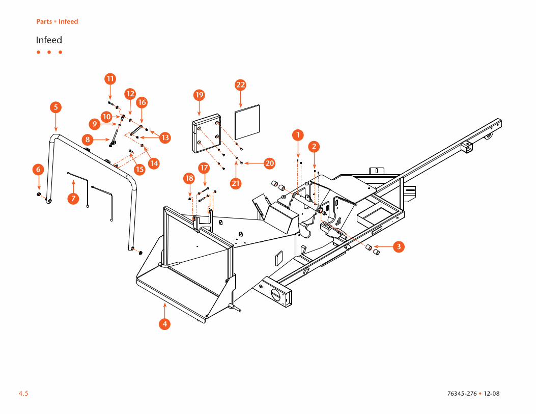
Infeed
Parts • Infeed
76345-276 • 12-08
32
35
34
319316
311
312
38
39310
36
33
313
320314315321
317318
31
322
37

4.6
Item Qty Part Number Description Item Qty Part Number Description
NS = not shown
1 2 26891-005 Grease, Fitting, 1/4”
2 2 22255-005 Screw, 1/4”-28 x 3/8”
3 4 23131-108 Bushing, Fiber, 1 1/2”
4 1 24717-270 Latch, 1/2”
5 1 40198-201 Control Bar
6 2 21733-201 Nut, Lock, 3/4”-10
7 2 24714-308 Cable, Safety
8 1 40321-901 Linkage, Valve
9 1 22531-006 Nut, 3/8”-24
10 1 24733-026 Ball Joint
11 1 21625-108 Bolt, 3/8”-16 x 1 3/4”
12 2 21161-661 Washer, Flat, 3/8”
13 2 21733-303 Nut, Lock, 3/8”-16
14 1 21161-311 Washer, Flat, 3/8”
15 1 21624-105 Bolt, 3/8”-16 x 1”
16 1 31168-462 Linkage, Valve
17 2 21624-061 Bolt, 5/16”-18 x 2 1/2”
18 4 21733-406 Nut, Lock, 5/16”-18
19 1 39234-205 Holder, Manual, Plastic
20 4 21661-114 Bolt, 1/4”-20 x 3/4”
21 4 21733-301 Nut, Lock, 1/4”-20
22 1 76345-276 Manual, Part
23 1 76347-276 Manual, Operator
Parts • Infeed
76345-276 • 12-08

4.7
Yoke and Feedwheel
Item Qty Part Number Description Item Qty Part Number Description
NS = not shown
1 1 40141-201 Feedwheel
2 2 23918-018 Bearing, FB, 1 1/2”
3 8 21624-107 Bolt, 3/8”-16 x 1 1/2”
4 8 21161-042 Washer, Flat, 3/8”
5 2 40200-061 Pivot Pin
6 2 21161-044 Washer, Flat, 1/2”
7 2 21624-253 Bolt, 1/2”-13 x 1”
8 1 40200-201 Yoke
9 2 24741-601 Spring
10 2 21711-203 Bolt, Eye, 1/2”-13 x 6”
11 4 21731-068 Nut, 1/2”-13
12 1 24114-726 Bushing, B-Loc
13 1 39216-416 Torque Arm
14 1 30880-701 Guard, Drive
15 2 21646-148 Bolt, 5/16”-18 x 1”
16 2 21167-017 Washer, Flat, 5/16”
17 1 26735-011 Motor, Hydraulic, 32.3 C.I.
18 4 21624-254 Bolt, 1/2”-13 x 1 1/4”
19 4 21161-044 Washer, Flat, 1/2”
20 1 40153-201 Pin, Yoke Lock
21 1 21129-313 Pin, Hair, 3/16” x 3 1/4”
Parts • Yoke and Feedwheel
76345-276 • 12-08
36
312
37
31
310
32
39
34
35
33
38
311
313314
316
315
319 318
317
320
321

4.8
Chipper Drum
Item Qty Part Number Description Item Qty Part Number Description
NS = not shown
1 2 23918-629 Bearing, FB, 2 7/16”
2 8 21624-255 Bolt, 1/2”-13 x 1 1/2”
3 8 21161-044 Washer, Flat 1/2”
4 2 24114-572 Bushing, B-Loc
5 2 39233-692 Knife
6 8 22424-404 Bolt, 3/4”-16 x 1 3/4”
7 1 30375-201 Drum
8 1 30392-201 Shaft, Drum
9 1 26709-003 Gear Pump
10 2 21624-254 Bolt, 1/2”-13 x 1 1/4”
11 2 21161-044 Washer, Flat 1/2”
12 1 30331-201 Guard, Drive
13 2 21646-148 Bolt, 5/16”-18 x 1”
14 2 21161-017 Washer, Flat 5/16”
15 1 30876-701 Torque Arm
16 1 24114-724 Coupler, B-Loc
Parts • Chipper Drum
76345-276 • 12-08
31
32
3334 38
310
311
312
31639
314
313
315
35
36
37
4.9
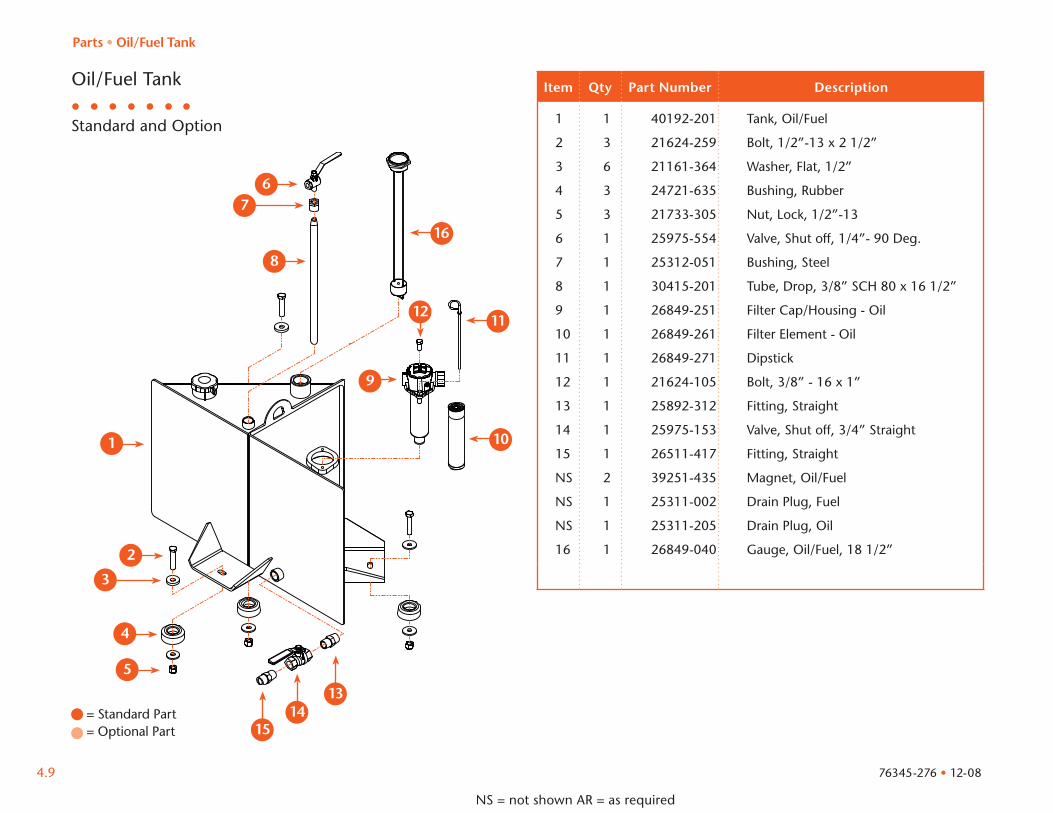
Standard and Option
= Standard Part= Optional Part
Oil/Fuel Tank Item Qty Part Number Description
NS = not shown AR = as required
1 1 40192-201 Tank, Oil/Fuel
2 3 21624-259 Bolt, 1/2”-13 x 2 1/2”
3 6 21161-364 Washer, Flat, 1/2”
4 3 24721-635 Bushing, Rubber
5 3 21733-305 Nut, Lock, 1/2”-13
6 1 25975-554 Valve, Shut off, 1/4”- 90 Deg.
7 1 25312-051 Bushing, Steel
8 1 30415-201 Tube, Drop, 3/8” SCH 80 x 16 1/2”
9 1 26849-251 Filter Cap/Housing - Oil
10 1 26849-261 Filter Element - Oil
11 1 26849-271 Dipstick
12 1 21624-105 Bolt, 3/8” - 16 x 1”
13 1 25892-312 Fitting, Straight
14 1 25975-153 Valve, Shut off, 3/4” Straight
15 1 26511-417 Fitting, Straight
NS 2 39251-435 Magnet, Oil/Fuel
NS 1 25311-002 Drain Plug, Fuel
NS 1 25311-205 Drain Plug, Oil
16 1 26849-040 Gauge, Oil/Fuel, 18 1/2”
Parts • Oil/Fuel Tank
76345-276 • 12-08
312
38
3637
39
310
311
16
313314
315
31
3233
34
35
4.10
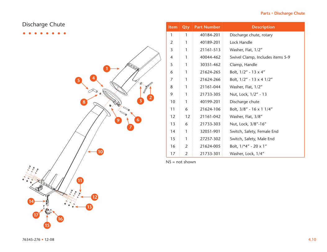
Discharge Chute Item Qty Part Number Description
NS = not shown
1 1 40184-201 Discharge chute, rotary
2 1 40189-201 Lock Handle
3 1 21161-513 Washer, Flat, 1/2”
4 1 40044-462 Swivel Clamp, Includes items 5-9
5 1 30351-462 Clamp, Handle
6 1 21624-265 Bolt, 1/2” - 13 x 4”
7 1 21624-266 Bolt, 1/2” - 13 x 4 1/2”
8 1 21161-044 Washer, Flat, 1/2”
9 1 21733-305 Nut, Lock, 1/2” - 13
10 1 40199-201 Discharge chute
11 6 21624-106 Bolt, 3/8” - 16 x 1 1/4”
12 12 21161-042 Washer, Flat, 3/8”
13 6 21733-303 Nut, Lock, 3/8”-16”
14 1 32051-901 Switch, Safety, Female End
15 1 27257-302 Switch, Safety, Male End
16 2 21624-005 Bolt, 1/*4” - 20 x 1”
17 2 21733-301 Washer, Lock, 1/4”
Parts • Discharge Chute
76345-276 • 12-08
1
8
9
1615
45
3637
3233
410
1412
13
17
11
4.11
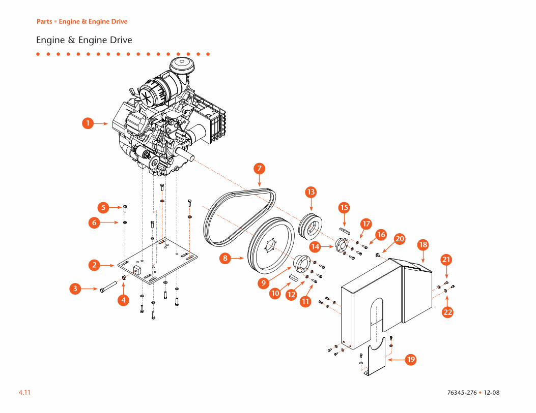
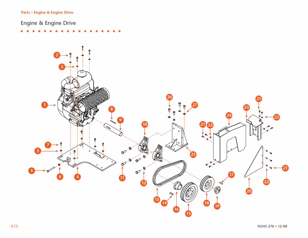
Engine & Engine Drive
Parts • Engine & Engine Drive
76345-276 • 12-08
37
316 320
317
31438
39310 312 311
322
318
31
32
313
315
321
34
33
35
36
319
4.12
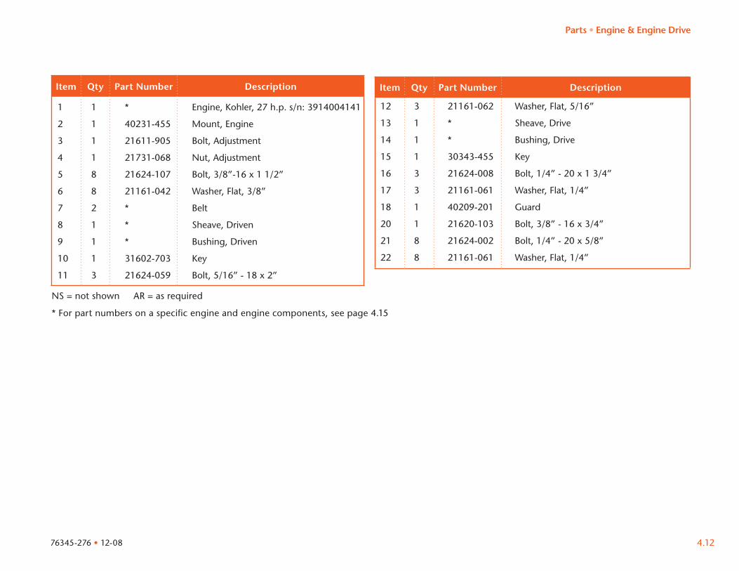
Item Qty Part Number Description Item Qty Part Number Description
1 1 * Engine, Kohler, 27 h.p. s/n: 3914004141
2 1 40231-455 Mount, Engine
3 1 21611-905 Bolt, Adjustment
4 1 21731-068 Nut, Adjustment
5 8 21624-107 Bolt, 3/8”-16 x 1 1/2”
6 8 21161-042 Washer, Flat, 3/8”
7 2 * Belt
8 1 * Sheave, Driven
9 1 * Bushing, Driven
10 1 31602-703 Key
11 3 21624-059 Bolt, 5/16” - 18 x 2”
12 3 21161-062 Washer, Flat, 5/16”
13 1 * Sheave, Drive
14 1 * Bushing, Drive
15 1 30343-455 Key
16 3 21624-008 Bolt, 1/4” - 20 x 1 3/4”
17 3 21161-061 Washer, Flat, 1/4”
18 1 40209-201 Guard
20 1 21620-103 Bolt, 3/8” - 16 x 3/4”
21 8 21624-002 Bolt, 1/4” - 20 x 5/8”
22 8 21161-061 Washer, Flat, 1/4”
NS = not shown AR = as required
* For part numbers on a specific engine and engine components, see page 4.15
Parts • Engine & Engine Drive
76345-276 • 12-08
Engine & Engine Drive
Parts • Engine & Engine Drive
39
38
317
313 314
321
322310
36
321 322
324
323
321326
327
325
31
32
311312
316
320
322
34
315
318 319
33
3733
35
4.13 76345-276 • 12-08
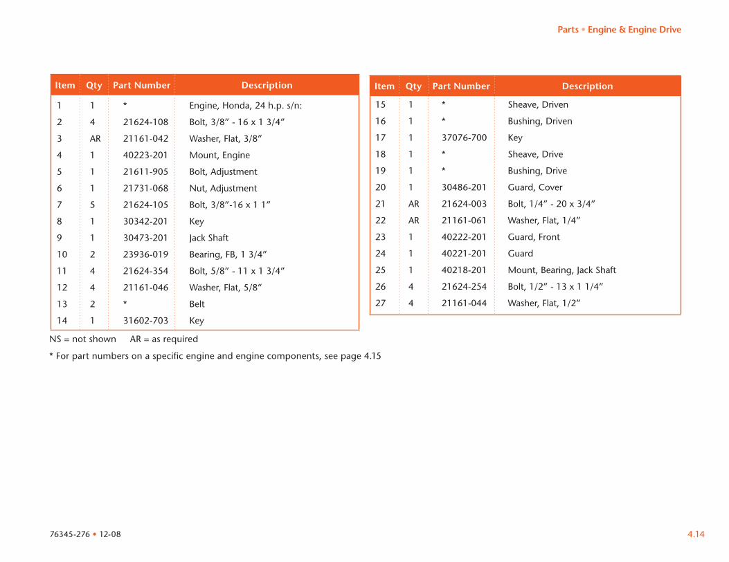
Item Qty Part Number Description Item Qty Part Number Description
1 1 * Engine, Honda, 24 h.p. s/n:
2 4 21624-108 Bolt, 3/8” - 16 x 1 3/4”
3 AR 21161-042 Washer, Flat, 3/8”
4 1 40223-201 Mount, Engine
5 1 21611-905 Bolt, Adjustment
6 1 21731-068 Nut, Adjustment
7 5 21624-105 Bolt, 3/8”-16 x 1 1”
8 1 30342-201 Key
9 1 30473-201 Jack Shaft
10 2 23936-019 Bearing, FB, 1 3/4”
11 4 21624-354 Bolt, 5/8” - 11 x 1 3/4”
12 4 21161-046 Washer, Flat, 5/8”
13 2 * Belt
14 1 31602-703 Key
15 1 * Sheave, Driven
16 1 * Bushing, Driven
17 1 37076-700 Key
18 1 * Sheave, Drive
19 1 * Bushing, Drive
20 1 30486-201 Guard, Cover
21 AR 21624-003 Bolt, 1/4” - 20 x 3/4”
22 AR 21161-061 Washer, Flat, 1/4”
23 1 40222-201 Guard, Front
24 1 40221-201 Guard
25 1 40218-201 Mount, Bearing, Jack Shaft
26 4 21624-254 Bolt, 1/2” - 13 x 1 1/4”
27 4 21161-044 Washer, Flat, 1/2”
NS = not shown AR = as required
* For part numbers on a specific engine and engine components, see page 4.15
Parts • Engine & Engine Drive
4.1476345-276 • 12-08
4.15
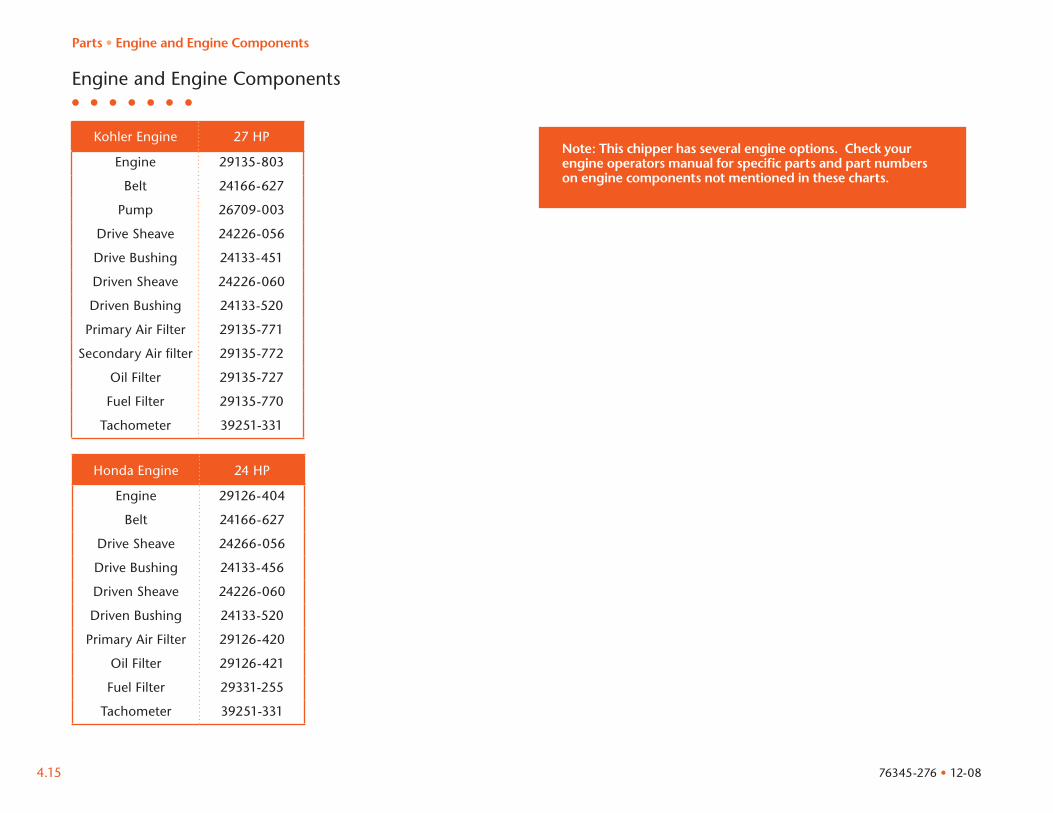
Kohler Engine 27 HP
Engine 29135-803
Belt 24166-627
Pump 26709-003
Drive Sheave 24226-056
Drive Bushing 24133-451
Driven Sheave 24226-060
Driven Bushing 24133-520
Primary Air Filter 29135-771
Secondary Air filter 29135-772
Oil Filter 29135-727
Fuel Filter 29135-770
Tachometer 39251-331
Honda Engine 24 HP
Engine 29126-404
Belt 24166-627
Drive Sheave 24266-056
Drive Bushing 24133-456
Driven Sheave 24226-060
Driven Bushing 24133-520
Primary Air Filter 29126-420
Oil Filter 29126-421
Fuel Filter 29331-255
Tachometer 39251-331
76345-276 • 12-08
Engine and Engine Components
Note: This chipper has several engine options. Check your engine operators manual for specific parts and part numbers on engine components not mentioned in these charts.
Parts • Engine and Engine Components
Moving parts can crush and cutFollow lockout proceduresbefore servicing.
39511-320
DANGER!39511-427
NEVER reach into the infeed chute.
wear loose clothing,scarves,gauntlet style gloves or gloves with holes while operating.
operate machine while alone. and operators manual
before operating.
DO NOT
NEVERREAD UNDERSTAND
39511-425
Remove tension springs and install yoke lockwhen working or reachingunder feed wheelFollow all lockout procedures beforeservicing.
4.16
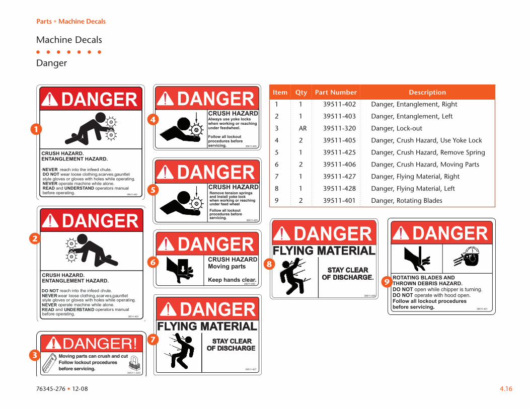
Machine Decals
Danger
Item Qty Part Number Description
1 1 39511-402 Danger, Entanglement, Right
2 1 39511-403 Danger, Entanglement, Left
3 AR 39511-320 Danger, Lock-out
4 2 39511-405 Danger, Crush Hazard, Use Yoke Lock
5 1 39511-425 Danger, Crush Hazard, Remove Spring
6 2 39511-406 Danger, Crush Hazard, Moving Parts
7 1 39511-427 Danger, Flying Material, Right
8 1 39511-428 Danger, Flying Material, Left
9 2 39511-401 Danger, Rotating Blades
Parts • Machine Decals
76345-276 • 12-08
1
2
5
3
8
4
6
7
9
39511-423
Raise Infeed tray and secure before towing.
WARNING
39511-424
DIRECT DRIVEWARNING
ALWAYS remove key before performing any maintenance.DO NOT use starter to unplug chipper.
4.17
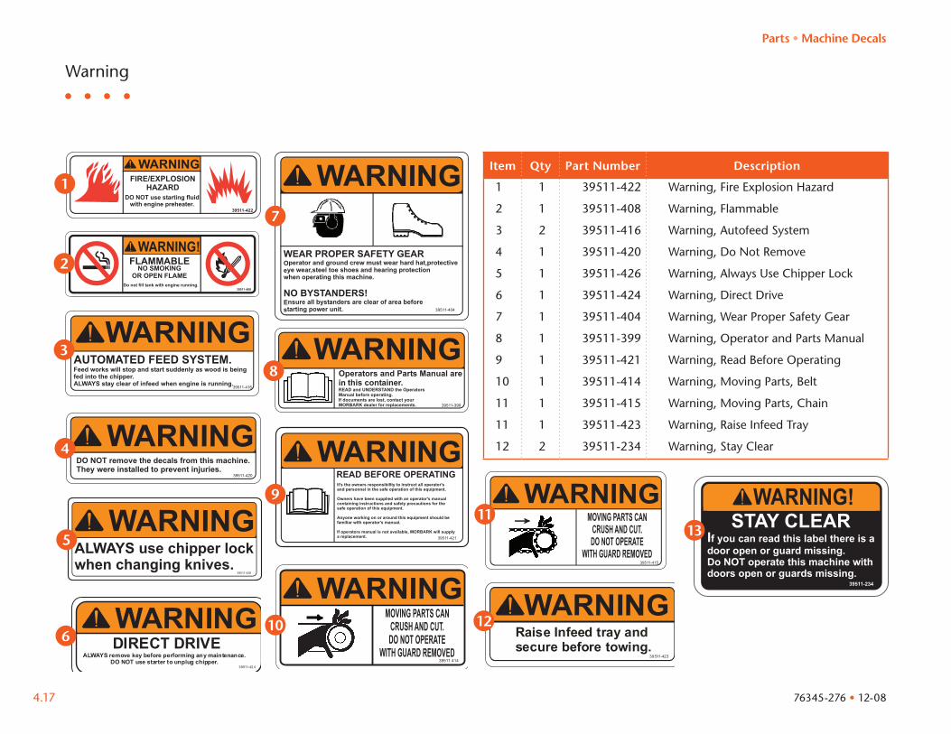
Warning
Item Qty Part Number Description
1 1 39511-422 Warning, Fire Explosion Hazard
2 1 39511-408 Warning, Flammable
3 2 39511-416 Warning, Autofeed System
4 1 39511-420 Warning, Do Not Remove
5 1 39511-426 Warning, Always Use Chipper Lock
6 1 39511-424 Warning, Direct Drive
7 1 39511-404 Warning, Wear Proper Safety Gear
8 1 39511-399 Warning, Operator and Parts Manual
9 1 39511-421 Warning, Read Before Operating
10 1 39511-414 Warning, Moving Parts, Belt
11 1 39511-415 Warning, Moving Parts, Chain
11 1 39511-423 Warning, Raise Infeed Tray
12 2 39511-234 Warning, Stay Clear
Parts • Machine Decals
76345-276 • 12-08
1
2
3
4
5
6
7
8
9
10
11
12
13
4.18
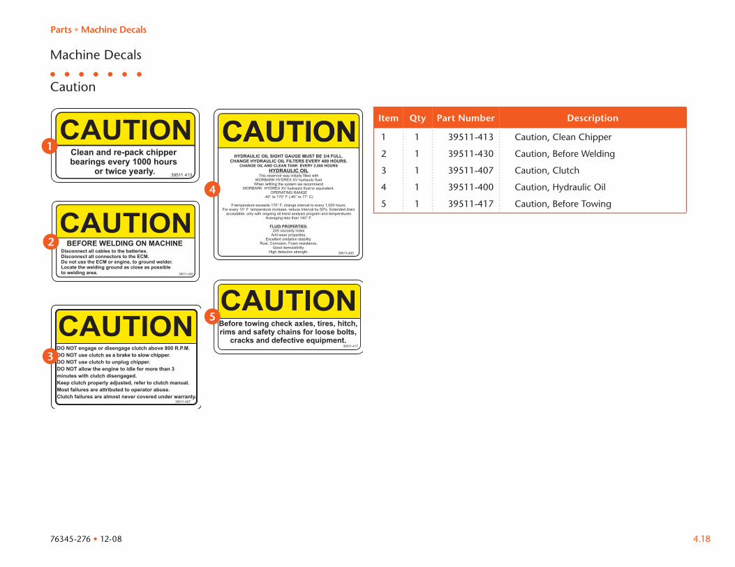
Machine Decals
Caution
Item Qty Part Number Description
1 1 39511-413 Caution, Clean Chipper
2 1 39511-430 Caution, Before Welding
3 1 39511-407 Caution, Clutch
4 1 39511-400 Caution, Hydraulic Oil
5 1 39511-417 Caution, Before Towing
Parts • Machine Decals
76345-276 • 12-08
1
2
3
4
5
4.19
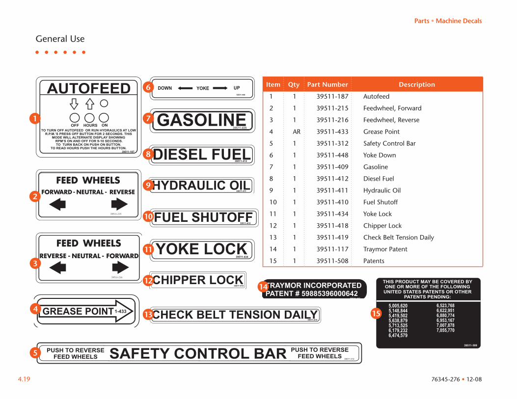
General Use
Item Qty Part Number Description
1 1 39511-187 Autofeed
2 1 39511-215 Feedwheel, Forward
3 1 39511-216 Feedwheel, Reverse
4 AR 39511-433 Grease Point
5 1 39511-312 Safety Control Bar
6 1 39511-448 Yoke Down
7 1 39511-409 Gasoline
8 1 39511-412 Diesel Fuel
9 1 39511-411 Hydraulic Oil
10 1 39511-410 Fuel Shutoff
11 1 39511-434 Yoke Lock
12 1 39511-418 Chipper Lock
13 1 39511-419 Check Belt Tension Daily
14 1 39511-117 Traymor Patent
15 1 39511-508 Patents
Parts • Machine Decals
76345-276 • 12-08
1
2
3
5
4
6
7
8
9
10
11
12
13
14
15
Item Qty Part Number Description
1
3
4
2
4.20
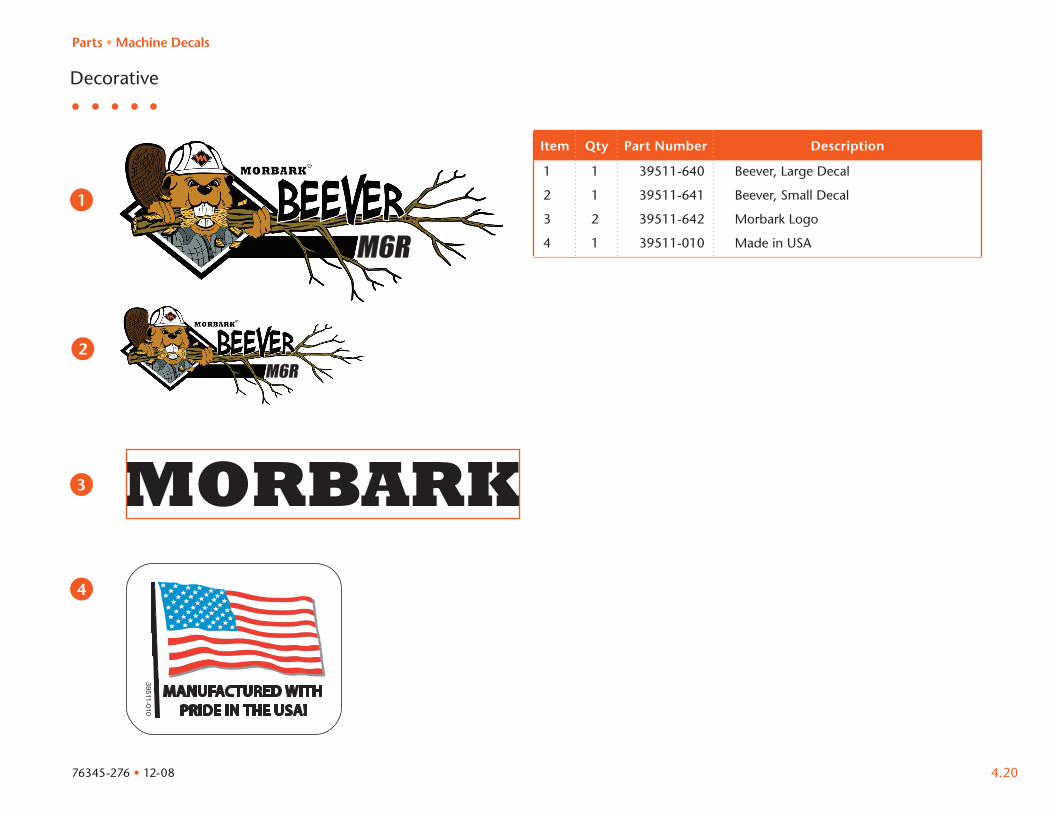
Decorative
1 1 39511-640 Beever, Large Decal
2 1 39511-641 Beever, Small Decal
3 2 39511-642 Morbark Logo
4 1 39511-010 Made in USA
Parts • Machine Decals
76345-276 • 12-08
General Maintenance
76345-276 • 12-08 5.1
Maintenance Overview . . . . . . . . . . . . . . . . . . . . . . . . . . . . . . . . . . . . . . 5.2
Air Filter. . . . . . . . . . . . . . . . . . . . . . . . . . . . . . . . . . . . . . . . . . . . . . . . . . 5.3
Lubrication . . . . . . . . . . . . . . . . . . . . . . . . . . . . . . . . . . . . . . . . . . . . . . . 5.4
Lubrication Points . . . . . . . . . . . . . . . . . . . . . . . . . . . . . . . . . . . . . . . . . . 5.4
Bolts & Torque . . . . . . . . . . . . . . . . . . . . . . . . . . . . . . . . . . . . . . . . . . . . 5.6
Belt Tension. . . . . . . . . . . . . . . . . . . . . . . . . . . . . . . . . . . . . . . . . . . . . . . 5.8
Chipper Knife . . . . . . . . . . . . . . . . . . . . . . . . . . . . . . . . . . . . . . . . . . . . . 5.10
Knife Anvil . . . . . . . . . . . . . . . . . . . . . . . . . . . . . . . . . . . . . . . . . . . . . . . . 5.14
Chipper Flange Bearing. . . . . . . . . . . . . . . . . . . . . . . . . . . . . . . . . . . . . . 5.16
Hydraulics . . . . . . . . . . . . . . . . . . . . . . . . . . . . . . . . . . . . . . . . . . . . . . . . 5.18
Hydraulic Pump Troubleshooting Guide . . . . . . . . . . . . . . . . . . . . . . . . . 5.20
Engine. . . . . . . . . . . . . . . . . . . . . . . . . . . . . . . . . . . . . . . . . . . . . . . . . . . 5.21
Fuel . . . . . . . . . . . . . . . . . . . . . . . . . . . . . . . . . . . . . . . . . . . . . . . . . . . . . 5.22
Tires . . . . . . . . . . . . . . . . . . . . . . . . . . . . . . . . . . . . . . . . . . . . . . . . . . . . 5.23
Chipper Troubleshooting Guide . . . . . . . . . . . . . . . . . . . . . . . . . . . . . . . 5.24
Pressure Guide . . . . . . . . . . . . . . . . . . . . . . . . . . . . . . . . . . . . . . . . . . . . 5.24
Electrical Schematic . . . . . . . . . . . . . . . . . . . . . . . . . . . . . . . . . . . . . . . . 5.25
Electrical Schematic . . . . . . . . . . . . . . . . . . . . . . . . . . . . . . . . . . . . . . . . 5.26
Hydraulic Schematic . . . . . . . . . . . . . . . . . . . . . . . . . . . . . . . . . . . . . . . . 5.27
Warranty . . . . . . . . . . . . . . . . . . . . . . . . . . . . . . . . . . . . . . . . . . . . . . . . . 5.28
Warranty Claims . . . . . . . . . . . . . . . . . . . . . . . . . . . . . . . . . . . . . . . . . . . .
5.292
Section 5

76345-276 • 12-085.2
General Maintenance • Overview
Maintenance Overview
Chipper Component Required Maintenance Start Up
8 hours
40 hours
400 hours
1000hours
Complete machine Visual inspection (see Safety section) X XClean machine X
Fasteners (except knife bolts) Assemble using Loc-Tite 242 (blue)
Engine oil Maintain according to OEM manual X XEngine air filter Tap filter and blow out with compressed air (see page 5.3) XDrum knife Inspect, sharpen or replace when chip quality deteriorates (see page 5.12) XDrum knife bolts Inspect when checking the knife, replace when worn or damaged1 XDrum knife clearance Adjust when changing knife XDrum anvil Inspect when changing knife, adjust or replace when worn or damaged XDrum drive belts Inspect, tighten to proper tension, replace when worn3 X XFeed wheel teeth Cut off and replace when worn
Tires Check air pressure before moving
Oil filters Replace XHydraulic oil Replace, check, increase to 3/4 full 2
Table 5.1 • Routine Maintenance Schedule
1. Apply a coating of anti-seize lubricant before tightening2. Change every 2,000 hours.
76345-276 • 12-08 5.3
General Maintenance • Air Filter
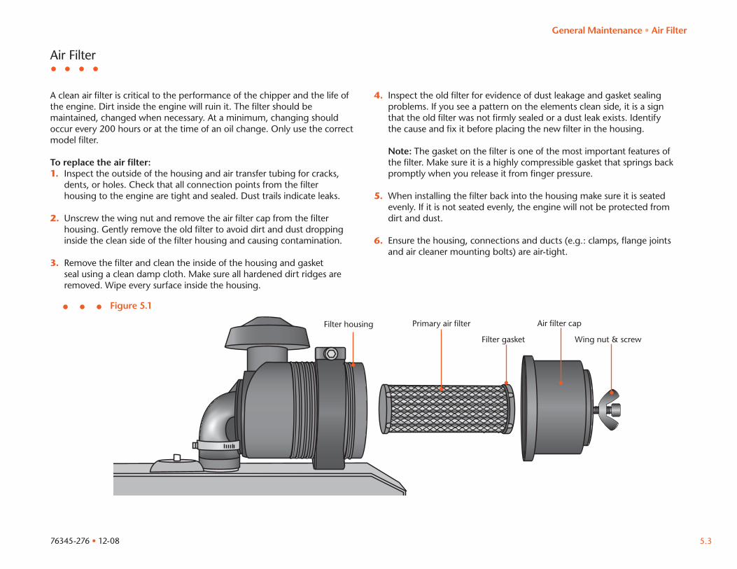
Air filter capPrimary air filter
Filter gasket
Filter housing
Air Filter
A clean air filter is critical to the performance of the chipper and the life of the engine. Dirt inside the engine will ruin it. The filter should be maintained, changed when necessary. At a minimum, changing should occur every 200 hours or at the time of an oil change. Only use the correct model filter.
To replace the air filter:1. Inspect the outside of the housing and air transfer tubing for cracks,
dents, or holes. Check that all connection points from the filter housing to the engine are tight and sealed. Dust trails indicate leaks.
2. Unscrew the wing nut and remove the air filter cap from the filter housing. Gently remove the old filter to avoid dirt and dust dropping inside the clean side of the filter housing and causing contamination.
3. Remove the filter and clean the inside of the housing and gasket seal using a clean damp cloth. Make sure all hardened dirt ridges are removed. Wipe every surface inside the housing.
4. Inspect the old filter for evidence of dust leakage and gasket sealing problems. If you see a pattern on the elements clean side, it is a sign that the old filter was not firmly sealed or a dust leak exists. Identify the cause and fix it before placing the new filter in the housing.
Note: The gasket on the filter is one of the most important features of the filter. Make sure it is a highly compressible gasket that springs back promptly when you release it from finger pressure.
5. When installing the filter back into the housing make sure it is seated evenly. If it is not seated evenly, the engine will not be protected from dirt and dust.
6. Ensure the housing, connections and ducts (e.g.: clamps, flange joints and air cleaner mounting bolts) are air-tight.
Figure 5.1
Wing nut & screw
Additional lubrication point on opposite side
76345-276 • 12-085.4
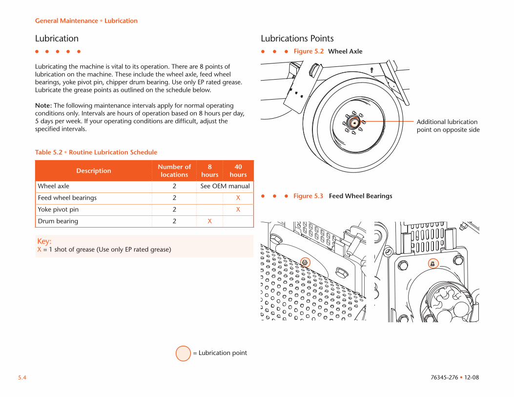
Lubricating the machine is vital to its operation. There are 8 points of lubrication on the machine. These include the wheel axle, feed wheel bearings, yoke pivot pin, chipper drum bearing. Use only EP rated grease. Lubricate the grease points as outlined on the schedule below.
Note: The following maintenance intervals apply for normal operating conditions only. Intervals are hours of operation based on 8 hours per day, 5 days per week. If your operating conditions are difficult, adjust the specified intervals.
Lubrication Lubrications PointsFigure 5.2
= Lubrication point
General Maintenance • Lubrication
Key:X = 1 shot of grease (Use only EP rated grease)
Description Number of locations
8 hours
40 hours
Wheel axle 2 See OEM manual
Feed wheel bearings 2 X
Yoke pivot pin 2 X
Drum bearing 2 X
Table 5.2 • Routine Lubrication Schedule
Figure 5.3 Feed Wheel Bearings
Wheel Axle
Additional lubrication point on opposite side
76345-276 • 12-08 5.5
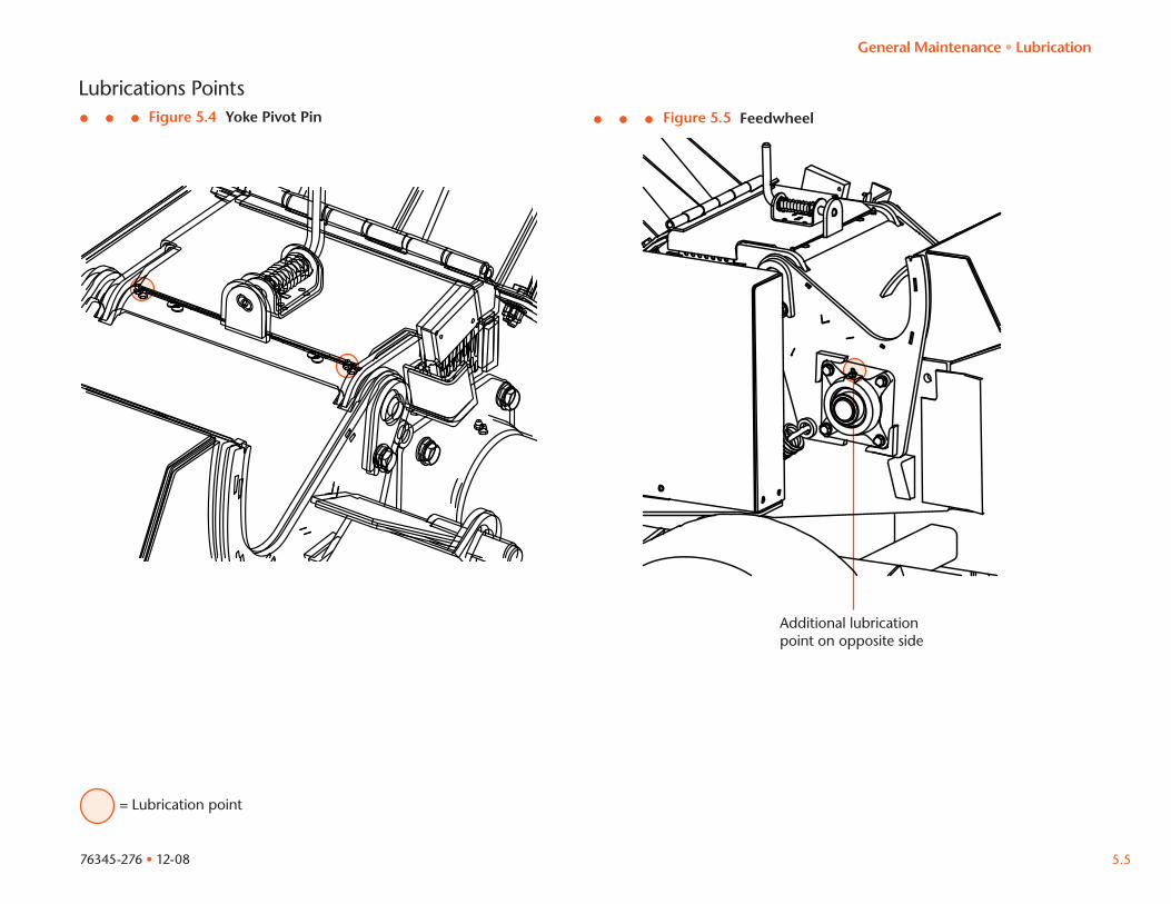
Lubrications PointsFigure 5.4
= Lubrication point
Yoke Pivot Pin Figure 5.5 Feedwheel
General Maintenance • Lubrication
76345-276 • 12-085.6
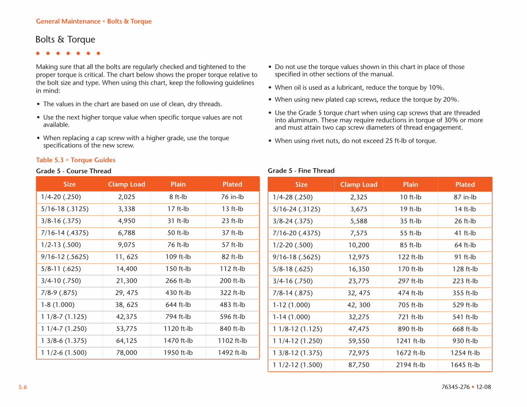
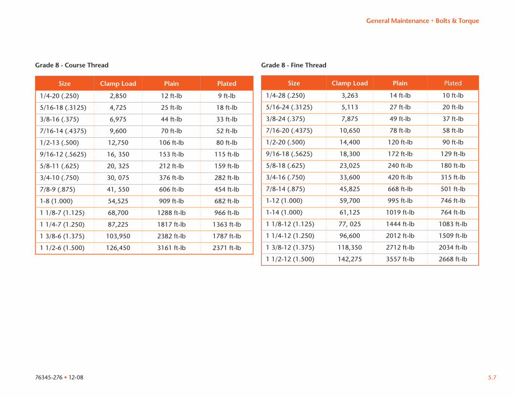
Making sure that all the bolts are regularly checked and tightened to the proper torque is critical. The chart below shows the proper torque relative to the bolt size and type. When using this chart, keep the following guidelines in mind:
• The values in the chart are based on use of clean, dry threads.
• Use the next higher torque value when specific torque values are not available.
• When replacing a cap screw with a higher grade, use the torque specifications of the new screw.
• Do not use the torque values shown in this chart in place of those specified in other sections of the manual.
• When oil is used as a lubricant, reduce the torque by 10%.
• When using new plated cap screws, reduce the torque by 20%.
• Use the Grade 5 torque chart when using cap screws that are threaded into aluminum. These may require reductions in torque of 30% or more and must attain two cap screw diameters of thread engagement.
• When using rivet nuts, do not exceed 25 ft-lb of torque.
Bolts & Torque
Table 5.3 • Torque Guides
Grade 5 - Course Thread
Size Clamp Load Plain Plated
1/4-20 (.250) 2,025 8 ft-lb 76 in-lb
5/16-18 (.3125) 3,338 17 ft-lb 13 ft-lb
3/8-16 (.375) 4,950 31 ft-lb 23 ft-lb
7/16-14 (.4375) 6,788 50 ft-lb 37 ft-lb
1/2-13 (.500) 9,075 76 ft-lb 57 ft-lb
9/16-12 (.5625) 11, 625 109 ft-lb 82 ft-lb
5/8-11 (.625) 14,400 150 ft-lb 112 ft-lb
3/4-10 (.750) 21,300 266 ft-lb 200 ft-lb
7/8-9 (.875) 29, 475 430 ft-lb 322 ft-lb
1-8 (1.000) 38, 625 644 ft-lb 483 ft-lb
1 1/8-7 (1.125) 42,375 794 ft-lb 596 ft-lb
1 1/4-7 (1.250) 53,775 1120 ft-lb 840 ft-lb
1 3/8-6 (1.375) 64,125 1470 ft-lb 1102 ft-lb
1 1/2-6 (1.500) 78,000 1950 ft-lb 1492 ft-lb
Size Clamp Load Plain Plated
1/4-28 (.250) 2,325 10 ft-lb 87 in-lb
5/16-24 (.3125) 3,675 19 ft-lb 14 ft-lb
3/8-24 (.375) 5,588 35 ft-lb 26 ft-lb
7/16-20 (.4375) 7,575 55 ft-lb 41 ft-lb
1/2-20 (.500) 10,200 85 ft-lb 64 ft-lb
9/16-18 (.5625) 12,975 122 ft-lb 91 ft-lb
5/8-18 (.625) 16,350 170 ft-lb 128 ft-lb
3/4-16 (.750) 23,775 297 ft-lb 223 ft-lb
7/8-14 (.875) 32, 475 474 ft-lb 355 ft-lb
1-12 (1.000) 42, 300 705 ft-lb 529 ft-lb
1-14 (1.000) 32,275 721 ft-lb 541 ft-lb
1 1/8-12 (1.125) 47,475 890 ft-lb 668 ft-lb
1 1/4-12 (1.250) 59,550 1241 ft-lb 930 ft-lb
1 3/8-12 (1.375) 72,975 1672 ft-lb 1254 ft-lb
1 1/2-12 (1.500) 87,750 2194 ft-lb 1645 ft-lb
Grade 5 - Fine Thread
General Maintenance • Bolts & Torque
76345-276 • 12-08 5.7
Size Clamp Load Plain Plated
1/4-20 (.250) 2,850 12 ft-lb 9 ft-lb
5/16-18 (.3125) 4,725 25 ft-lb 18 ft-lb
3/8-16 (.375) 6,975 44 ft-lb 33 ft-lb
7/16-14 (.4375) 9,600 70 ft-lb 52 ft-lb
1/2-13 (.500) 12,750 106 ft-lb 80 ft-lb
9/16-12 (.5625) 16, 350 153 ft-lb 115 ft-lb
5/8-11 (.625) 20, 325 212 ft-lb 159 ft-lb
3/4-10 (.750) 30, 075 376 ft-lb 282 ft-lb
7/8-9 (.875) 41, 550 606 ft-lb 454 ft-lb
1-8 (1.000) 54,525 909 ft-lb 682 ft-lb
1 1/8-7 (1.125) 68,700 1288 ft-lb 966 ft-lb
1 1/4-7 (1.250) 87,225 1817 ft-lb 1363 ft-lb
1 3/8-6 (1.375) 103,950 2382 ft-lb 1787 ft-lb
1 1/2-6 (1.500) 126,450 3161 ft-lb 2371 ft-lb
Grade 8 - Course Thread
Size Clamp Load Plain Plated
1/4-28 (.250) 3,263 14 ft-lb 10 ft-lb
5/16-24 (.3125) 5,113 27 ft-lb 20 ft-lb
3/8-24 (.375) 7,875 49 ft-lb 37 ft-lb
7/16-20 (.4375) 10,650 78 ft-lb 58 ft-lb
1/2-20 (.500) 14,400 120 ft-lb 90 ft-lb
9/16-18 (.5625) 18,300 172 ft-lb 129 ft-lb
5/8-18 (.625) 23,025 240 ft-lb 180 ft-lb
3/4-16 (.750) 33,600 420 ft-lb 315 ft-lb
7/8-14 (.875) 45,825 668 ft-lb 501 ft-lb
1-12 (1.000) 59,700 995 ft-lb 746 ft-lb
1-14 (1.000) 61,125 1019 ft-lb 764 ft-lb
1 1/8-12 (1.125) 77, 025 1444 ft-lb 1083 ft-lb
1 1/4-12 (1.250) 96,600 2012 ft-lb 1509 ft-lb
1 3/8-12 (1.375) 118,350 2712 ft-lb 2034 ft-lb
1 1/2-12 (1.500) 142,275 3557 ft-lb 2668 ft-lb
Grade 8 - Fine Thread
General Maintenance • Bolts & Torque
CAUTION
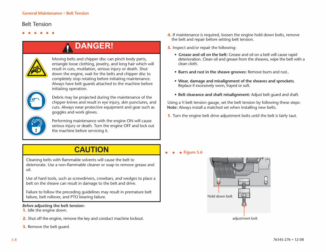
DANGER!Moving belts and chipper disc can pinch body parts, entangle loose clothing, jewelry, and long hair which will result in cuts, mutilation, serious injury or death. Shut down the engine, wait for the belts and chipper disc to completely stop rotating before initiating maintenance. Always have belt guards attached to the machine before initiating operation.
Debris may be projected during the maintenance of the chipper knives and result in eye injury, skin punctures, and cuts. Always wear protective equipment and gear such as goggles and work gloves.
Performing maintenance with the engine ON will cause serious injury or death. Turn the engine OFF and lock out the machine before servicing it.
Cleaning belts with flammable solvents will cause the belt to deteriorate. Use a non-flammable cleaner or soap to remove grease and oil.
Use of hard tools, such as screwdrivers, crowbars, and wedges to place a belt on the sheave can result in damage to the belt and drive.
Failure to follow the preceding guidelines may result in premature belt failure, belt rollover, and PTO bearing failure.
Belt Tension
Before adjusting the belt tension:1.Idle the engine down.
2. Shut off the engine, remove the key and conduct machine lockout.
3. Remove the belt guard.
Figure 5.6
4. If maintenance is required, loosen the engine hold down bolts, remove the belt and repair before setting belt tension.
5. Inspect and/or repair the following:
• Grease and oil on the belt: Grease and oil on a belt will cause rapid deterioration. Clean oil and grease from the sheaves, wipe the belt with a clean cloth.
• Burrs and rust in the sheave grooves: Remove burrs and rust..
• Wear, damage and misalignment of the sheaves and sprockets. Replace if excessively worn, frayed or soft.
• Belt clearance and shaft misalignment: Adjust belt guard and shaft.
Using a V-belt tension gauge, set the belt tension by following these steps:Note: Always install a matched set when installing new belts.
1. Turn the engine belt drive adjustment bolts until the belt is fairly taut.
adjustment bolt
Hold down bolt
General Maintenance • Belt Tension
76345-276 • 12-085.8
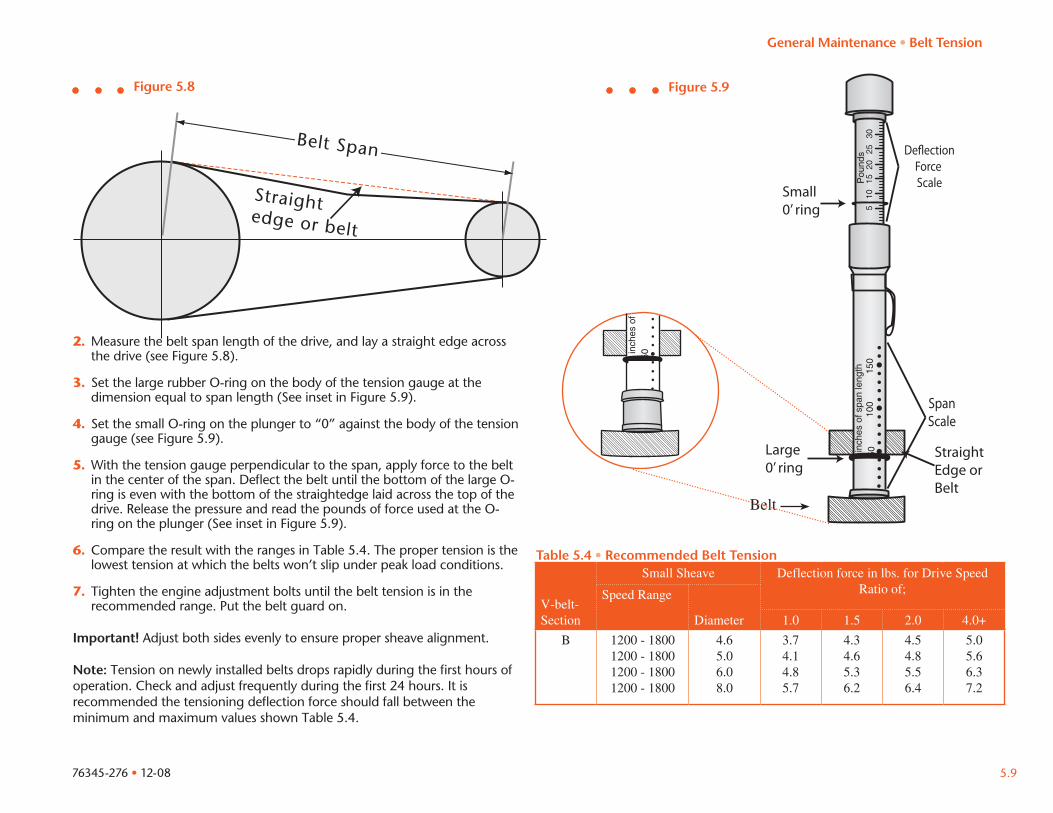
Belt Span
Straight edge or belt
2. Measure the belt span length of the drive, and lay a straight edge across the drive (see Figure 5.8).
3. Set the large rubber O-ring on the body of the tension gauge at the dimension equal to span length (See inset in Figure 5.9).
4. Set the small O-ring on the plunger to “0” against the body of the tension gauge (see Figure 5.9).
5. With the tension gauge perpendicular to the span, apply force to the belt in the center of the span. Deflect the belt until the bottom of the large O- ring is even with the bottom of the straightedge laid across the top of the drive. Release the pressure and read the pounds of force used at the O- ring on the plunger (See inset in Figure 5.9).
6. Compare the result with the ranges in Table 5.4. The proper tension is the lowest tension at which the belts won’t slip under peak load conditions.
7. Tighten the engine adjustment bolts until the belt tension is in the recommended range. Put the belt guard on.
Important! Adjust both sides evenly to ensure proper sheave alignment.
Note: Tension on newly installed belts drops rapidly during the first hours of operation. Check and adjust frequently during the first 24 hours. It is recommended the tensioning deflection force should fall between the minimum and maximum values shown Table 5.4.
Figure 5.8 Figure 5.9
5010
015
0in
ches
of s
pan
leng
thP
ound
s30
2520
1510
5
Small 0’ ring
Large 0’ ring
De�ectionForce Scale
SpanScale
StraightEdge or Belt
Belt
Table 5.4 • Recommended Belt Tension
V-belt-Section
Small Sheave Deflection force in lbs. for Drive Speed Ratio of;Speed Range
Diameter 1.0 1.5 2.0 4.0+
B 1200 - 1800 1200 - 1800 1200 - 1800 1200 - 1800
4.65.06.08.0
3.74.14.85.7
4.34.65.36.2
4.54.85.56.4
5.05.66.37.2
General Maintenance • Belt Tension
50in
ches
of
76345-276 • 12-08 5.9
OFF ON START
ENGINE SW.
76345-276 • 12-085.10
Chipper Knife
DANGER!A rotating chipper disc can pinch body parts, entangle loose clothing, jewelry, and long hair which may result in cuts, mutilation, serious injury or death. Before initiating maintenance throttle the engine down and shut the engine OFF. Wait for the chipper disc to completely stop rotating and insert the disc lock pin.
The chipper disc will coast for several minutes after the machine is shut off. Do not open the chipper hood until the disc rotation has completely stopped. Serious injury, mutilation or death can occur.
Debris may be projected during the maintenance of the chipper knife and result in eye injury, skin punctures, and cuts. Always wear protective equipment and gear such as goggles and work gloves.
CAUTIONExcessive heat, indicated by discoloration of the knife edge, will lead to microscopic cracks that can cause the knife to break when it is put back into service. Do not use knife that have been exposed to excessive heat from sharpening.
To ensure maximum efficiency of the chipping operation the chipper knife must be properly maintained. The time between sharpening or replacement will depend on the type of wood and operating conditions. Indication of dull knife include poor quality, excessive oversize chips and poor feed characteristics. Always maintain proper knife sharpness. It is important to follow these guidelines to ensure efficient chipping:
• Use original Morbark Inc. knife with the correct steel composition and hardness. Immediately replace worn knife.
• Keep the knife edge sharp and anvil square.
• Maintain the proper clearance between the chipper knife and anvil.
• Use the correct hardware to mount the knife to the holder and maintain the correct torque to the bolt. Keep the knife pocket and holder clean and free of debris.
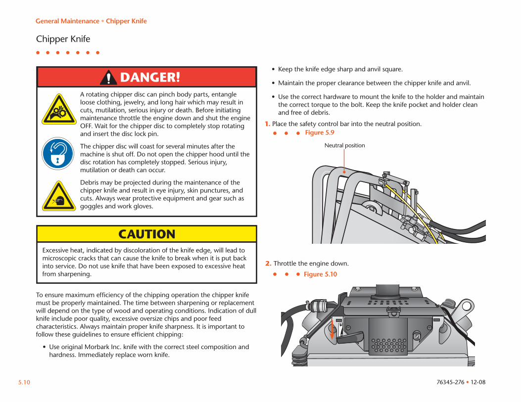
1. Place the safety control bar into the neutral position.
2. Throttle the engine down.
Figure 5.9
Neutral position
Figure 5.10
General Maintenance • Chipper Knife
OFF ON START
ENGINE SW.
76345-276 • 12-08 5.11
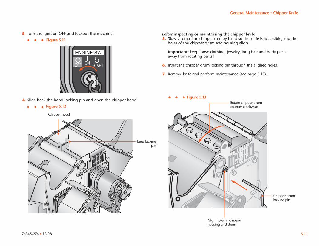
3. Turn the ignition OFF and lockout the machine.
Figure 5.11Before inspecting or maintaining the chipper knife:5. Slowly rotate the chipper rum by hand so the knife is accessible, and the
holes of the chipper drum and housing align. Important: keep loose clothing, jewelry, long hair and body parts
away from rotating parts!
6. Insert the chipper drum locking pin through the aligned holes.
7. Remove knife and perform maintenance (see page 5.13).
Chipper hood
Figure 5.12
4. Slide back the hood locking pin and open the chipper hood.Figure 5.13
Rotate chipper drumcounter-clockwise
Hood locking pin
Align holes in chipper housing and drum
Chipper drum locking pin
General Maintenance • Chipper Knife
76345-276 • 12-08 5.13
To Sharpen the Knife Edge:When sharpening the knife edge use proper grinding techniques (hand file, power belt sander with fine paper or conventional knife grinder with coolant system) to reduce the possibility of excessive heat build up and provide a good cutting edge. Do not use straight wheel grinding. This method will result in a hollow or concave effect and shorten the life of the knife.
Use a non-petroleum base coolant such as De Santo (orange label) grinding coolant when using a grinding machine. Mix approximately one part coolant to 50 parts of water. The coolant should be applied on the wheel about 1” above the knife with full pressure. This will keep the wheel clear and free to cut without burning or damaging knife. Do not overfeed the grinding machine.
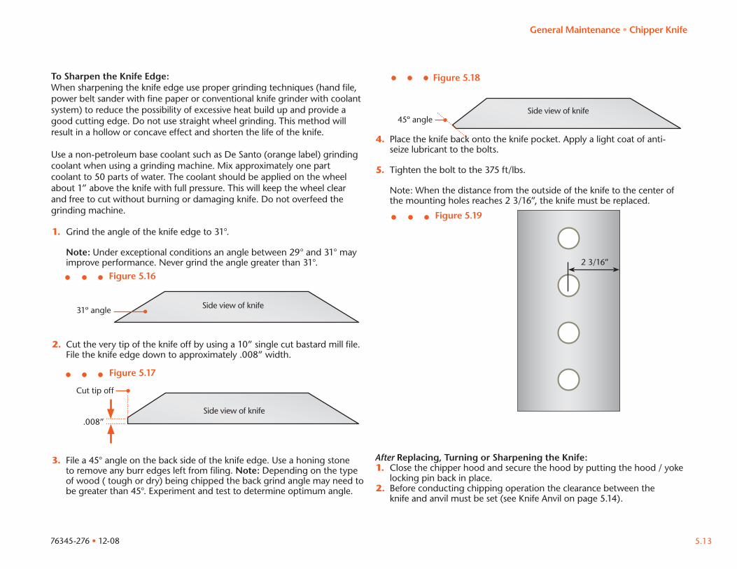
1. Grind the angle of the knife edge to 31°.
Note: Under exceptional conditions an angle between 29° and 31° may improve performance. Never grind the angle greater than 31°.
2. Cut the very tip of the knife off by using a 10” single cut bastard mill file. File the knife edge down to approximately .008” width.
Figure 5.16
31º angle Side view of knife
Cut tip off
.008”Side view of knife
3. File a 45° angle on the back side of the knife edge. Use a honing stone to remove any burr edges left from filing. Note: Depending on the type of wood ( tough or dry) being chipped the back grind angle may need to be greater than 45°. Experiment and test to determine optimum angle.
45º angleSide view of knife
Figure 5.17
Figure 5.18
4. Place the knife back onto the knife pocket. Apply a light coat of anti- seize lubricant to the bolts.
5. Tighten the bolt to the 375 ft/lbs.
Note: When the distance from the outside of the knife to the center of the mounting holes reaches 2 3/16”, the knife must be replaced.
After Replacing, Turning or Sharpening the Knife:1. Close the chipper hood and secure the hood by putting the hood / yoke
locking pin back in place.2. Before conducting chipping operation the clearance between the knife and anvil must be set (see Knife Anvil on page 5.14).
Figure 5.19
2 3/16”
General Maintenance • Chipper Knife
76345-276 • 12-08 5.13
WARNING!Sharp edges and flying debris may cause serious injury. Always wear protective gloves and goggles while maintaining the chipper knife.
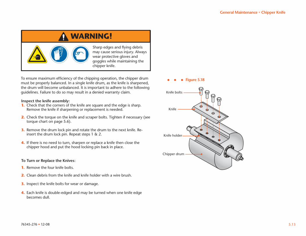
To ensure maximum efficiency of the chipping operation, the chipper drum must be properly balanced. In a single knife drum, as the knife is sharpened, the drum will become unbalanced. It is important to adhere to the following guidelines. Failure to do so may result in a denied warranty claim.
Figure 5.18
Knife
Knife bolts
Inspect the knife assembly:1. Check that the corners of the knife are square and the edge is sharp.
Remove the knife if sharpening or replacement is needed.
2. Check the torque on the knife and scraper bolts. Tighten if necessary (see torque chart on page 5.6).
3. Remove the drum lock pin and rotate the drum to the next knife. Re-insert the drum lock pin. Repeat steps 1 & 2.
4. If there is no need to turn, sharpen or replace a knife then close the chipper hood and put the hood locking pin back in place.
Chipper drum
Knife holder
To Turn or Replace the Knives:
1. Remove the four knife bolts.
2. Clean debris from the knife and knife holder with a wire brush.
3. Inspect the knife bolts for wear or damage.
4. Each knife is double-edged and may be turned when one knife edge becomes dull.
General Maintenance • Chipper Knife
76345-276 • 12-085.14
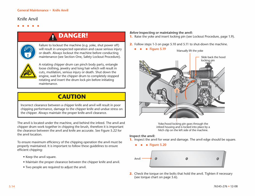
Knife Anvil
DANGER!Failure to lockout the machine (e.g. yoke, shut power off) will result in unexpected operation and cause serious injury or death. Always lockout the machine before conducting maintenance (see Section One, Safety Lockout Procedure).
A rotating chipper drum can pinch body parts, entangle loose clothing, jewelry and long hair which will result in cuts, mutilation, serious injury or death. Shut down the engine, wait for the chipper drum to completely stopped rotating and insert the drum lock pin before initiating maintenance.
CAUTIONIncorrect clearance between a chipper knife and anvil will result in poor chipping performance, damage to the chipper knife and undue stress on the chipper. Always maintain the proper knife-anvil clearance.
The anvil is located under the machine, and behind the infeed. The anvil and chipper drum work together in chipping the brush, therefore it is important the clearance between the anvil and knife are accurate. See Figure 5.22 for the anvil location.
To ensure maximum efficiency of the chipping operation the anvil must be properly maintained. It is important to follow these guidelines to ensure efficient chipping:
• Keep the anvil square.
• Maintain the proper clearance between the chipper knife and anvil.
• Two people are required to adjust the anvil.
Before inspecting or maintaining the anvil:1. Raise the yoke and insert locking pin (see Lockout Procedure, page 1.9).
2. Follow steps 1-3 on page 5.10 and 5.11 to shut-down the machine.
Inspect the anvil:1. Inspect the anvil for wear and damage. The anvil edge should be square.
Yoke/hood locking pin goes through the infeed housing and is locked into place by a hitch clip on the left side of the machine.
Figure 5.19 Manually lift the yoke
2. Check the torque on the bolts that hold the anvil. Tighten if necessary (see torque chart on page 5.6).
Figure 5.20
Anvil
Slide back the hood locking pin
General Maintenance • Knife Anvil
76345-276 • 12-08 5.15
General Maintenance • Knife Anvil
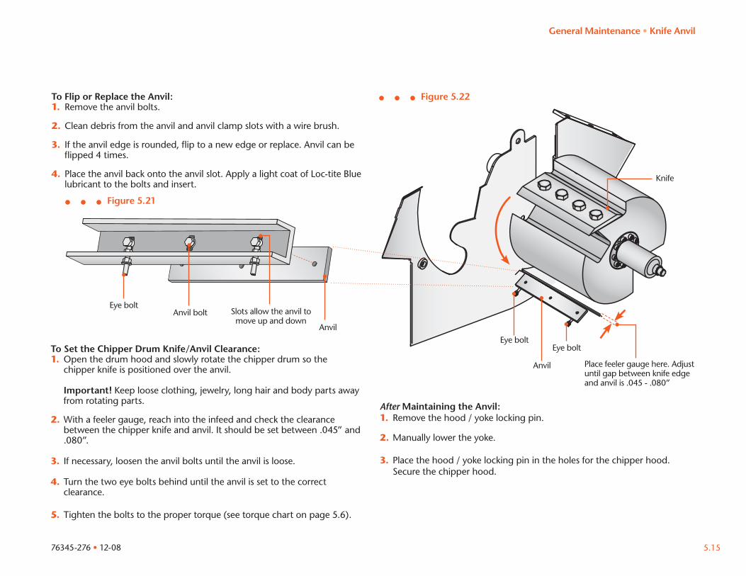
To Flip or Replace the Anvil:1. Remove the anvil bolts.
2. Clean debris from the anvil and anvil clamp slots with a wire brush.
3. If the anvil edge is rounded, flip to a new edge or replace. Anvil can be flipped 4 times.
4. Place the anvil back onto the anvil slot. Apply a light coat of Loc-tite Blue lubricant to the bolts and insert.
To Set the Chipper Drum Knife/Anvil Clearance:1. Open the drum hood and slowly rotate the chipper drum so the chipper knife is positioned over the anvil. Important! Keep loose clothing, jewelry, long hair and body parts away from rotating parts.
2. With a feeler gauge, reach into the infeed and check the clearance between the chipper knife and anvil. It should be set between .045” and .080”.
3. If necessary, loosen the anvil bolts until the anvil is loose.
4. Turn the two eye bolts behind until the anvil is set to the correct clearance.
5. Tighten the bolts to the proper torque (see torque chart on page 5.6).
Figure 5.21
Anvil boltEye bolt
Anvil
Slots allow the anvil to move up and down
Figure 5.22
Place feeler gauge here. Adjust until gap between knife edge and anvil is .045 - .080”
Anvil
Eye boltEye bolt
After Maintaining the Anvil:1. Remove the hood / yoke locking pin.
2. Manually lower the yoke.
3. Place the hood / yoke locking pin in the holes for the chipper hood. Secure the chipper hood.
Knife
DANGER!
76345-276 • 12-085.16
Chipper Flange Bearing
Performing maintenance with the power source ON may result in unexpected operation of the machine and may cause serious injury or death. Turn OFF and lock out the power source before servicing.
The chipper flange bearings support the chipper drum shaft and should be greased according to the maintenance schedule.
Before performing maintenance on the chipper bearings:1. Follow steps 1-3 on page 5.10 and 5.11 to shut-down the machine.
2. Inspect the chipper drum shaft. Ensure that it is smooth, free of any nicks or cuts, straight and clean.
3. Inspect the bearing for contamination.
4. Protect the bearing from exposure to dirt or moisture.
After performing maintenance on the chipper bearings:1. Slide the chipper bearings on both the idler and drive side of the drum
after you have inserted the drum into the base.
2. Start the bolts into both the flange bearings after applying a coat of Loc Tite Blue, then tighten.
3. Spin the drum, if it hits on any side of the inside of the drum, move the drum to the opposite side just enough to clear the drum side. Re-spin the drum and repeat if necessary until the drum does not hit on any side and is centered into the base.
4. Slide the flange bearing lock collars onto the drum shaft and lock onto the bearings. Tighten the lock collar allen head bolts until tight. Then take out the allen head bolts and identify the mark left by the bolt making contact with the shaft and drill a hole in the shaft to seat the end of the bolt into the shaft
5. With a torque wrench, torque the flange bearing bolts to correct torque.
General Maintenance • Chipper Flange Bearing
76345-276 • 12-08 5.17
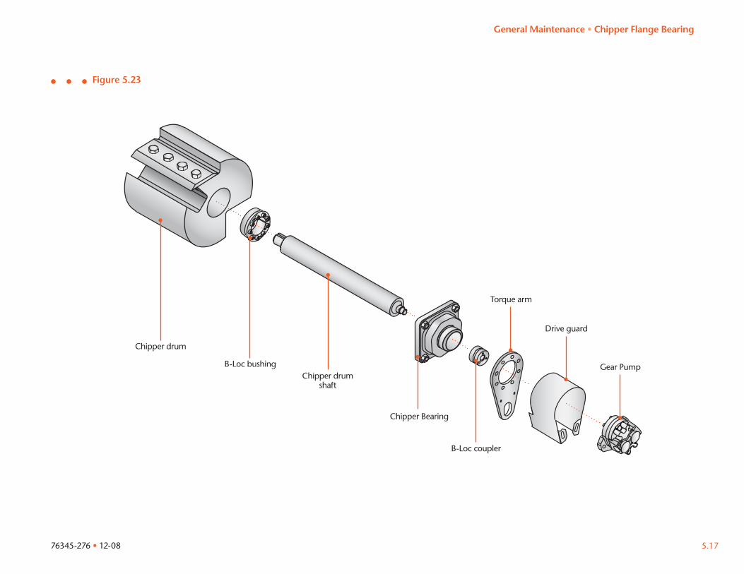
Figure 5.23
Chipper Bearing
Torque arm
Chipper drum shaft
Chipper drum
B-Loc bushing
B-Loc coupler
Drive guard
Gear Pump
General Maintenance • Chipper Flange Bearing
76345-276 • 12-085.18
Hydraulics
CAUTIONNever increase hydraulic pressure settings. Doing so voids the manufacturer’s warranty.
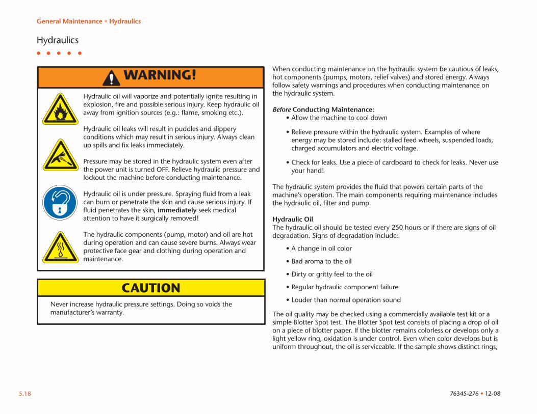
When conducting maintenance on the hydraulic system be cautious of leaks, hot components (pumps, motors, relief valves) and stored energy. Always follow safety warnings and procedures when conducting maintenance on the hydraulic system.
Before Conducting Maintenance:• Allow the machine to cool down
• Relieve pressure within the hydraulic system. Examples of where energy may be stored include: stalled feed wheels, suspended loads, charged accumulators and electric voltage.
• Check for leaks. Use a piece of cardboard to check for leaks. Never use your hand!
The hydraulic system provides the fluid that powers certain parts of the machine’s operation. The main components requiring maintenance includes the hydraulic oil, filter and pump.
Hydraulic OilThe hydraulic oil should be tested every 250 hours or if there are signs of oil degradation. Signs of degradation include:
• A change in oil color
• Bad aroma to the oil
• Dirty or gritty feel to the oil
• Regular hydraulic component failure
• Louder than normal operation sound
The oil quality may be checked using a commercially available test kit or a simple Blotter Spot test. The Blotter Spot test consists of placing a drop of oil on a piece of blotter paper. If the blotter remains colorless or develops only a light yellow ring, oxidation is under control. Even when color develops but is uniform throughout, the oil is serviceable. If the sample shows distinct rings,
WARNING!Hydraulic oil will vaporize and potentially ignite resulting in explosion, fire and possible serious injury. Keep hydraulic oil away from ignition sources (e.g.: flame, smoking etc.).
Hydraulic oil leaks will result in puddles and slippery conditions which may result in serious injury. Always clean up spills and fix leaks immediately.
Pressure may be stored in the hydraulic system even after the power unit is turned OFF. Relieve hydraulic pressure and lockout the machine before conducting maintenance.
Hydraulic oil is under pressure. Spraying fluid from a leak can burn or penetrate the skin and cause serious injury. If fluid penetrates the skin, immediately seek medical attention to have it surgically removed!
The hydraulic components (pump, motor) and oil are hot during operation and can cause severe burns. Always wear protective face gear and clothing during operation and maintenance.
General Maintenance • Hydraulics
76345-276 • 12-08 5.19
the fluid should be changed. When a dark spot remains in the middle but lighter-colored oil migrates outward in the blotter paper, the oil has or is about to dump sludge or other products into the system. This indicates that the time for fluid replacement has passed.
Under normal conditions hydraulic oil should be changed every 2,000 operating hours or yearly, which ever comes first. In more severe conditions it should be changed every 1,000 hours or six months. Always use hydraulic oil that contains anti-wear additives. Always keep the level of oil in the tank at 3/4 full. Failure to do so can result in air getting into the pump, a reduction of oil pressure, and slow operation.
Hydraulic Oil FilterThe hydraulic oil filter should be replaced after 500 hours of operation or when the hydraulic oil is changed. Always use a filter rated at 10 micron.
Hydraulic Oil PumpThe hydraulic pump is critical to the operation of the chipper. Operators should always be alert for possible problems with the pump during operation. Symptoms indicating problems with the pump include (see Table 5.6):
• A noisy pump
• Overheating
• High discharge pressure
• Pump not pumping
• Low system pressure
• Sluggish start-up
Troubleshooting the hydraulic system involves talking with the operators, understanding the schematics and inspection of the machine. After identifying the problem determine the root causes. It is possible there is more than one cause of the malfunction.
Start by creating a list of possible causes. Put the easiest ones to eliminate and do not require dis-assembly or down time first. Systematically test, eliminate or repair possible causes.
Initiate corrective action to avoid future maintenance problems and operation downtime.
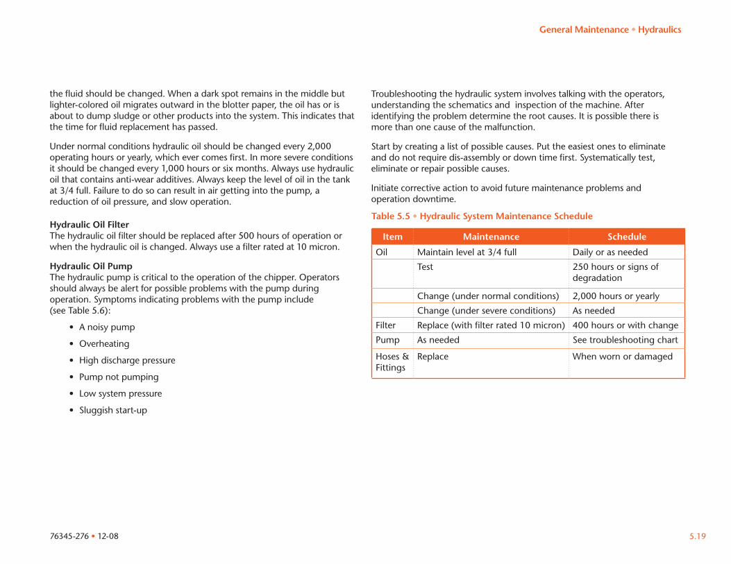
Table 5.5 • Hydraulic System Maintenance Schedule
Item Maintenance Schedule
Oil Maintain level at 3/4 full Daily or as needed
Test 250 hours or signs of degradation
Change (under normal conditions) 2,000 hours or yearly
Change (under severe conditions) As needed
Filter Replace (with filter rated 10 micron) 400 hours or with change
Pump As needed See troubleshooting chart
Hoses & Fittings
Replace When worn or damaged
General Maintenance • Hydraulics
76345-276 • 12-085.20
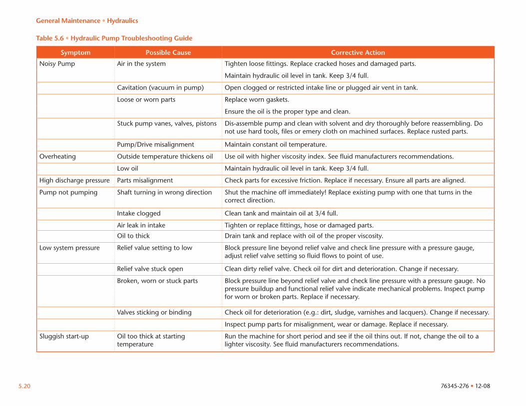
Symptom Possible Cause Corrective Action
Noisy Pump Air in the system Tighten loose fittings. Replace cracked hoses and damaged parts.
Maintain hydraulic oil level in tank. Keep 3/4 full.
Cavitation (vacuum in pump) Open clogged or restricted intake line or plugged air vent in tank.
Loose or worn parts Replace worn gaskets.
Ensure the oil is the proper type and clean.
Stuck pump vanes, valves, pistons Dis-assemble pump and clean with solvent and dry thoroughly before reassembling. Do not use hard tools, files or emery cloth on machined surfaces. Replace rusted parts.
Pump/Drive misalignment Maintain constant oil temperature.
Overheating Outside temperature thickens oil Use oil with higher viscosity index. See fluid manufacturers recommendations.
Low oil Maintain hydraulic oil level in tank. Keep 3/4 full.
High discharge pressure Parts misalignment Check parts for excessive friction. Replace if necessary. Ensure all parts are aligned.
Pump not pumping Shaft turning in wrong direction Shut the machine off immediately! Replace existing pump with one that turns in the correct direction.
Intake clogged Clean tank and maintain oil at 3/4 full.
Air leak in intake Tighten or replace fittings, hose or damaged parts.
Oil to thick Drain tank and replace with oil of the proper viscosity.
Low system pressure Relief value setting to low Block pressure line beyond relief valve and check line pressure with a pressure gauge, adjust relief valve setting so fluid flows to point of use.
Relief valve stuck open Clean dirty relief valve. Check oil for dirt and deterioration. Change if necessary.
Broken, worn or stuck parts Block pressure line beyond relief valve and check line pressure with a pressure gauge. No pressure buildup and functional relief valve indicate mechanical problems. Inspect pump for worn or broken parts. Replace if necessary.
Valves sticking or binding Check oil for deterioration (e.g.: dirt, sludge, varnishes and lacquers). Change if necessary.
Inspect pump parts for misalignment, wear or damage. Replace if necessary.
Sluggish start-up Oil too thick at starting temperature
Run the machine for short period and see if the oil thins out. If not, change the oil to a lighter viscosity. See fluid manufacturers recommendations.
Table 5.6 • Hydraulic Pump Troubleshooting Guide
General Maintenance • Hydraulics
122º
104º
86º
68º
50º
32º
14º
-4º
-22º
-40º
-67º
50º
40º
30º
20º
10º
0º
-10º
-20º
-30º
-40º
-55º
Single Viscosity
Air Temperature
ºC ºF
Multi Viscosity
SAE
40
SAE
30
SAE
10W
SAE
20W
40SW
20
SAE
15W
40
SAE
15W
30
SAE
10W
20
Arc
tic o
il
76345-276 • 12-08 5.21
Engine
WARNING!Wood dust and chipping material in the engine area may ignite and result in fire, burns or serious injury. Clean the engine area before operation of the machine and when excessive material build-up occurs. Do not clean the engine area with the engine running!
CAUTIONRefer to the engines OEM manual for specific maintenance guidelines and procedures. Failure to follow the engine OEM guidelines and procedures may result in a void of the engine OEM warranty.
The engine area should be cleaned before every use and if there is excessive material build-up (wood dust, chips) during operation. Always turn the engine OFF before cleaning the engine area.
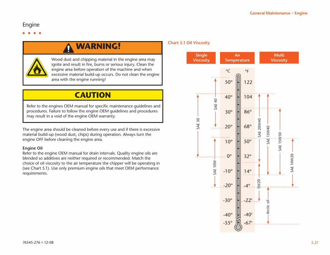
Engine OilRefer to the engine OEM manual for drain intervals. Quality engine oils are blended so additives are neither required or recommended. Match the choice of oil viscosity to the air temperature the chipper will be operating in (see Chart 5.1). Use only premium engine oils that meet OEM performance requirements.
Chart 5.1 Oil Viscosity
General Maintenance • Engine
1/4 3/4
1/2
E F
76345-276 • 12-085.22
Fuel
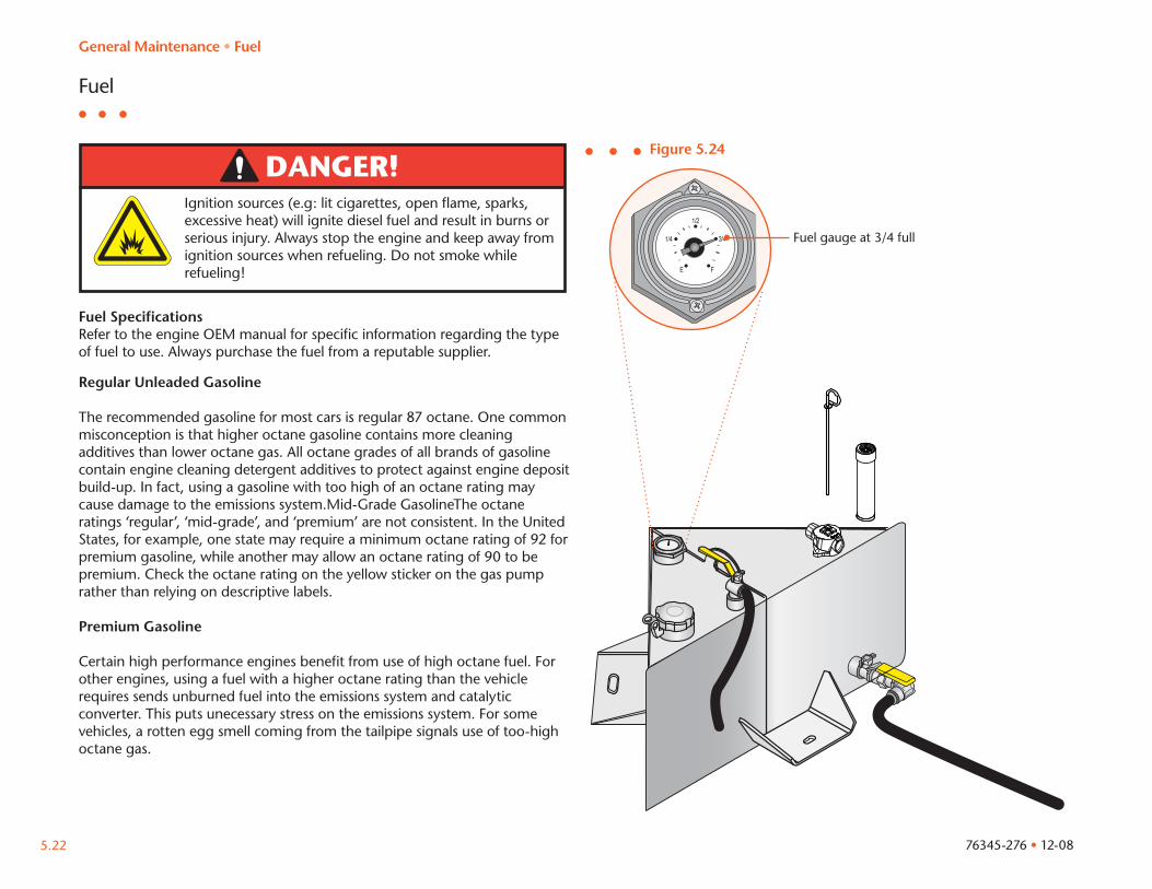
DANGER!Ignition sources (e.g: lit cigarettes, open flame, sparks, excessive heat) will ignite diesel fuel and result in burns or serious injury. Always stop the engine and keep away from ignition sources when refueling. Do not smoke while refueling!
Fuel SpecificationsRefer to the engine OEM manual for specific information regarding the type of fuel to use. Always purchase the fuel from a reputable supplier.
Regular Unleaded Gasoline
The recommended gasoline for most cars is regular 87 octane. One common misconception is that higher octane gasoline contains more cleaning additives than lower octane gas. All octane grades of all brands of gasoline contain engine cleaning detergent additives to protect against engine deposit build-up. In fact, using a gasoline with too high of an octane rating may cause damage to the emissions system.Mid-Grade GasolineThe octane ratings ‘regular’, ‘mid-grade’, and ‘premium’ are not consistent. In the United States, for example, one state may require a minimum octane rating of 92 for premium gasoline, while another may allow an octane rating of 90 to be premium. Check the octane rating on the yellow sticker on the gas pump rather than relying on descriptive labels.
Premium Gasoline
Certain high performance engines benefit from use of high octane fuel. For other engines, using a fuel with a higher octane rating than the vehicle requires sends unburned fuel into the emissions system and catalytic converter. This puts unecessary stress on the emissions system. For some vehicles, a rotten egg smell coming from the tailpipe signals use of too-high octane gas.
Fuel gauge at 3/4 full
Figure 5.24
General Maintenance • Fuel
Tires
WARNING!
76345-276 • 12-08 5.23
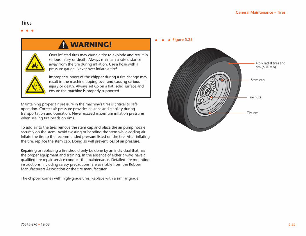
Maintaining proper air pressure in the machine’s tires is critical to safe operation. Correct air pressure provides balance and stability during transportation and operation. Never exceed maximum inflation pressures when sealing tire beads on rims.
To add air to the tires remove the stem cap and place the air pump nozzle securely on the stem. Avoid twisting or bending the stem while adding air. Inflate the tire to the recommended pressure listed on the tire. After inflating the tire, replace the stem cap. Doing so will prevent loss of air pressure.
Repairing or replacing a tire should only be done by an individual that has the proper equipment and training. In the absence of either always have a qualified tire repair service conduct the maintenance. Detailed tire mounting instructions, including safety precautions, are available from the Rubber Manufacturers Association or the tire manufacturer.
The chipper comes with high-grade tires. Replace with a similar grade.
Over inflated tires may cause a tire to explode and result in serious injury or death. Always maintain a safe distance away from the tire during inflation. Use a hose with a pressure gauge. Never over inflate a tire!
Improper support of the chipper during a tire change may result in the machine tipping over and causing serious injury or death. Always set up on a flat, solid surface and ensure the machine is properly supported.
Figure 5.25
Stem cap
Tire rim
Tire nuts
4 ply radial tires and rim (5.70 x 8)
General Maintenance • Tires
76345-276 • 12-085.24
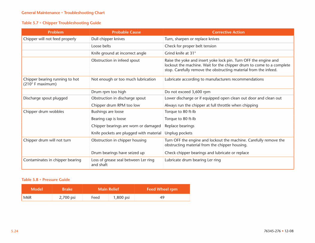
Problem Probable Cause Corrective Action
Chipper will not feed properly Dull chipper knives Turn, sharpen or replace knives
Loose belts Check for proper belt tension
Knife ground at incorrect angle Grind knife at 31°
Obstruction in infeed spout Raise the yoke and insert yoke lock pin. Turn OFF the engine and lockout the machine. Wait for the chipper drum to come to a complete stop. Carefully remove the obstructing material from the infeed.
Chipper bearing running to hot(210° F maximum)
Not enough or too much lubrication Lubricate according to manufacturers recommendations
Drum rpm too high Do not exceed 3,600 rpm
Discharge spout plugged Obstruction in discharge spout Lower discharge or if equipped open clean out door and clean out
Chipper drum RPM too low Always run the chipper at full throttle when chipping
Chipper drum wobbles Bushings are loose Torque to 80 ft-lb
Bearing cap is loose Torque to 80 ft-lb
Chipper bearings are worn or damaged Replace bearings
Knife pockets are plugged with material Unplug pockets
Chipper drum will not turn Obstruction in chipper housing Turn OFF the engine and lockout the machine. Carefully remove the obstructing material from the chipper housing.
Drum bearings have seized up Check chipper bearings and lubricate or replace
Contaminates in chipper bearing Loss of grease seal between Ler ring and shaft
Lubricate drum bearing Ler ring
General Maintenance • Troubleshooting Chart
Table 5.7 • Chipper Troubleshooting Guide
Table 5.8 • Pressure Guide
Model Brake Main Relief Feed Wheel rpm
M6R 2,700 psi Feed 1,800 psi 49
76345-276 • 12-08 5.25
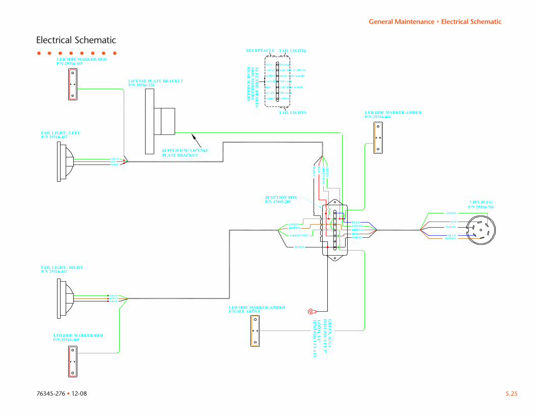
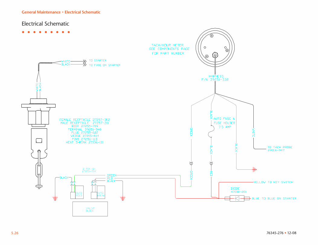
Electrical Schematic
General Maintenance • Electrical Schematic
76345-276 • 12-085.26
Electrical Schematic
General Maintenance • Electrical Schematic
76345-276 • 12-08 5.27
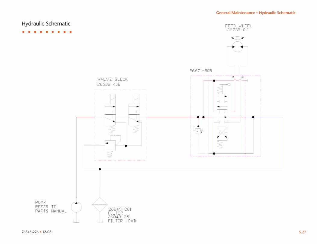
Hydraulic Schematic
General Maintenance • Hydraulic Schematic
76345-276 • 12-085.28
Purchasers Exclusive Remedy. The exclusive remedy for the purchaser in the event the equipment does not conform to this Warranty, shall be the repair or replacement of the equipment is returned to Morbark’s factory 8507 Winn Road, Winn, Michigan, or at such other location designated in writing by Morbark. Morbark is not responsible for the cost of transport or related charges in connection with return of any equipment to Morbark under this Warranty. Morbark shall have sole discretion to determine whether, and to what extent, the equipment is defective. If Morbark determines the equipment is not covered by this Warranty, the equipment shall be returned to the purchaser at purchasers expense.
Warranty Validation. Morbark shall be under no warranty obligation unless a Warranty Validation Report is completed and returned to Morbark, Inc., 8507 Winn Road, Winn Michigan, properly dated and signed by the purchaser within thirty (30) days of delivery of the equipment.
Disclaimer of Warranties. This Warranty is in lieu of all other Warranties express or implied. Morbark makes no other Warranties as to the equipment, and in particular, makes no implied Warranty of merchantability or fitness for a particular purpose, which are expressly disclaimed.
Limitation of Damages. Morbark shall not be liable for any incidental or consequential damages, directly or by subrogation, including but not limited to any claims for lost profits, downtime, or loss of use, in the event the equipment is defective or does not comply with any Warranty.
Warranty
,
,
®
8507 Winn Road, Winn Michigan989•866•2381
Morbark, Inc. (Morbark) warrants to the original purchaser that this product will be free from defects in materials and workmanship under normal use and operating conditions subject to the conditions and exclusions stated below. No representative, agent, dealer of Morbark, or any other person is authorized to modify, expand, or extend this warranty in any manner, or make any representation on Morbark’s behalf in connection with the sale of any equipment covered by this Warranty.
Warranty Period. The Warranty period is as follows: 1. One (1) years from the date of original delivery with extended one - year warranty on Morbark manufactured components only
for hand fed brush chippers.
Exclusions. This Warranty shall not apply to: 1. Equipment that has been subjected to misuse, neglect,
modification, alteration, accident, or lack of normal maintenance or service.
2. Replacement of routine maintenance items and wear parts such
as knives, anvils, hammers, screens, belts, bearings, etc. 3. Fire damage. 4. Components manufactured by others that are warranted by the
manufacturers thereof, including engines, engine components, batteries, tires, etc.
General Maintenance • Warranty
76345-276 • 12-08 5.29
Morbark, Inc. is committed to making sure that your machine is operational and productive at all times. We carry an extensive inventory of parts so that if a part on your machine fails, we’ll get a replacement part to you as soon as possible.
To better help you please follow these steps:
1. Contact us at (800) 255-8839 and order the part • Let us know whether the part is under warranty. We will send
to you a claim form(s) that includes instructions for filling it out.
2. Fill out the claim form(s) • If there are labor expenses that need to be reviewed for
reimbursement, then a completed and approved “Prior Authorization” form must be attached to the warranty claim form and sent to Morbark, Inc.
• All replacement parts are invoiced to the customer. A credit is issued after the completed warranty claim form and failed part are received at Morbark, Inc. and the cause of failure determined to be a defect in materials or workmanship.
3. Install the new part and send the defective part to Morbark, Inc.
Warranty Claims • Attach the Morbark, Inc. invoice received for the replacement
part. If the replacement part was purchased from a Morbark distributor, then attach the distributor’s invoice. Morbark retains the right to refuse any claim when original Morbark replacement parts have not been used.
• Ship the defective part to Morbark, Inc., 8507 S. Winn Road, Winn, MI, 48896 Attention: Warranty Returns. All returned parts must be shipped freight prepaid.
Use the pink copy and Morbark invoice as a packing slip. Keep the golden rod copy for your records and any future inquiries concerning the claim.
• The white, yellow, and green copies need to be mailed to Morbark Warranty, PO Box 1000, Winn, MI, 48896. Both the part and claim form need to be received for warranty consideration.
If you have any questions about the warranty claim process, please call us and ask for the warranty department.
General Maintenance • Warranty Claims

76345-276 • 12-085.30
,
,
®
P.O. Box 100Winn, Michigan 48896www.morbark.com
OFF ON START
ENGINE SW.
©2008 Morbark, Inc.