monthly progress report nofederalelectricityandwaterauthority.gov.ae/en/opendata/documents/3... ·...
TRANSCRIPT

WAM
Client: FEDERAL ELECTRICITY AND WATER AUTHORITY (FEWA) Project: STANDARD SPECIFICATIONS FOR WATER WORKS
Engineer WATER DIRECTORATE / ASSET MANAGEMENT DEPARTMENT
Title: Technical Terms / Chapter 4/ Engineering Specifications / Pipeline Works Specifications.
PS03-GRP PIPES MATERIALS & INSTALLATION
Office: DUBAI Order: Document: MWA_PRO_07/WAM-04-PS03 Rev:
DEC/20142
Sheet: 1 Of: 28
Federal Electricity & Water Authority
Water Directorate
Asset Management Department
STANDARD SPECIFICATIONS
FOR WATER WORKS
TECHNICAL TERMS
Chapter – 4
Engineering Specifications
E – Pipeline works Specifications
PS 03
GRP PIPES - MATERIALS & INSTALLATION

WAM
Client: FEDERAL ELECTRICITY AND WATER AUTHORITY (FEWA) Project: STANDARD SPECIFICATIONS FOR WATER WORKS
Engineer WATER DIRECTORATE / ASSET MANAGEMENT DEPARTMENT
Title: Technical Terms / Chapter 4/ Engineering Specifications / Pipeline Works Specifications.
PS03-GRP PIPES MATERIALS & INSTALLATION
Office: DUBAI Order: Document: MWA_PRO_07/WAM-04-PS03 Rev:
DEC/20142
Sheet: 2 Of: 28
SPECIFICATION FOR GRP PIPES-MATERIALS & INSTALLATION
TABLE OF CONTENT
A. SPECIFICATION FOR GRP PIPES, FITTINGS AND ACCESSORIES
1. GENERAL
2. CODES AND STANDARDS
3. SITE CONDITION
4. DESIGN CONSIDERATIONS
5. TECHNICAL REQUIREMENTS
5.1 General
5.2 Materials
5.3 Raw Material
5.4 Wall Thickness:
5.5 Length
5.6 Diameter
5.7 Stiffness
5.8 Axial Tensile Strength
5.9 Hoop Tensile Strength
5.10 Ignition Loss
5.11 Joints
5.11.1 Flexible Joints
5.11.2 Rigid Joints
5.11.3 Reinforced Overlay Joints ( butt & wrap)
6. WORKMANSHIP
7. FITTINGS
8. ULTRA-VIOLET RESISTANT
9. INSPECTION & TESTING
9.1 Inspection
9.2 Testing
9.2.1 Testing Reports to be Submitted by Manufacturer
9.3 Acceptance Criteria
9.4 Rejection
10. PACKING AND SHIPMENT
10.1 Storage
10.2 Marking
11. VENDOR DOCUMENTATION
12. WARRANTY

WAM
Client: FEDERAL ELECTRICITY AND WATER AUTHORITY (FEWA) Project: STANDARD SPECIFICATIONS FOR WATER WORKS
Engineer WATER DIRECTORATE / ASSET MANAGEMENT DEPARTMENT
Title: Technical Terms / Chapter 4/ Engineering Specifications / Pipeline Works Specifications.
PS03-GRP PIPES MATERIALS & INSTALLATION
Office: DUBAI Order: Document: MWA_PRO_07/WAM-04-PS03 Rev:
DEC/20142
Sheet: 3 Of: 28
B. SPECIFICATION FOR INSTALLATION, TESTING AND COMMISSIONING
OF GRP PIPING SYSTEM
1. SCOPE
2. APPLICABLE STANDARDS AND CODES
3. SITE CONDITIONS
4. DESIGN CONSIDERATIONS
4.1 Trench
4.1.1 Soft Spots
4.1.2 Hard Spots
4.1.3 Corrective Action
4.1.4 Over Excavation
4.1.5 Ground Water
4.2 Pipe Bed
4.3 Trench Construction
4.4 Thrust and Anchor Blocks To Pressure Pipelines
5. CONSTRUCTION REQUIREMENTS
5.1 Pipe Installation
5.2 Concrete Surround
5.3 Backfilling /Pipe Surround Material
5.4 Embankment for Pipelines
5.5 Road Crossings
5.6 Connection to Existing Pipelines
6. TESTING AND COMMESSIONING
6.1 Hydrostatic Pressure Tests
6.2 Precautions Prior to Testing
6.3 Apparent losses
6.4 Repair
6.5 Flushing and Disinfection
7. PACKING AND SHIPMENT

WAM
Client: FEDERAL ELECTRICITY AND WATER AUTHORITY (FEWA) Project: STANDARD SPECIFICATIONS FOR WATER WORKS
Engineer WATER DIRECTORATE / ASSET MANAGEMENT DEPARTMENT
Title: Technical Terms / Chapter 4/ Engineering Specifications / Pipeline Works Specifications.
PS03-GRP PIPES MATERIALS & INSTALLATION
Office: DUBAI Order: Document: MWA_PRO_07/WAM-04-PS03 Rev:
DEC/20142
Sheet: 4 Of: 28
A. SPECIFICATION FOR GRP PIPES, FITTINGS AND ACCESSORIES 1. GENERAL
This specification covers the requirement for material, Construction, Testing and Commissioning of the Glass Reinforced Plastic (GRP) Piping Systems for water transmission and distribution pipelines conveying pressurized, desalinated, chemically treated and brackish water.The requirement for pipes which are laid down in this specification are also valid for GRP- fittings.
2. CODES AND STANDARDS
a) International Organization for Standardization (ISO)
ISO 62 Plastics – Determination of Water Absorption. ISO 1172 Textile Glass Reinforced Plastics – Determination of Loss on Ignition.
b) American Water Works Association
AWWA C950 Glass Fibre Reinforced Thermosetting Resin Pressure Pipes. AWWA M 45 Manual of water supply practiced Fibre glass pipe design.
c) American Society for Testing and Materials (ASTM)
ASTM C-581 Standard test method for Chemical resistance of Thermosetting
resins used in glass fibre reinforced structures. ASTM D 638 Test Method for Tensile Properties of Plastics
ASTM D 695 Compressive Properties of Rigid Plastics ASTM D 696 Coefficient of liner Thermal Expansion of plastics.
ASTM F477 Standard Specification for Elastomeric Seals (Gaskets) for Joining Plastic Pipe ASTM D 1599 ASTM D 1599 Short – Time Hydraulic Failure Pressure of Plastic Pipe, Tubing and Fittings. ASTM D- 2240 Test Method for Rubber Property- Durometer Hardness. ASTM D 2290 Apparent Tensile Strength of Ring or Tubular Plastics and
Reinforced Plastics by split Disk Method. ASTM D-2310 Standard Classification for Machine – Made Reinforced
Thermosetting –Resin pipe. ASTM D 2412 External loading Properties of Plastic Pipe by Parallel – Plate
Loading. ASTM D 2563 Classifying Visual Defects in Glass- Reinforced Plastic Laminate
Parts. ASTM D 2583 Identification Hardness of Rigid Plastics by Means of a Barcol
Impressor.
ASTM C613 / C613M - 97(2008) Standard Test Method for Constituent Content of Composite Prepreg
ASTM D 2924 External Pressure Resistance of Fibre glass Pipe and Fittings ASTM D 2925 Beam Deflection of reinforced thermosetting Plastic Pipe UNDER
full Bore Flow.

WAM
Client: FEDERAL ELECTRICITY AND WATER AUTHORITY (FEWA) Project: STANDARD SPECIFICATIONS FOR WATER WORKS
Engineer WATER DIRECTORATE / ASSET MANAGEMENT DEPARTMENT
Title: Technical Terms / Chapter 4/ Engineering Specifications / Pipeline Works Specifications.
PS03-GRP PIPES MATERIALS & INSTALLATION
Office: DUBAI Order: Document: MWA_PRO_07/WAM-04-PS03 Rev:
DEC/20142
Sheet: 5 Of: 28
ASTM D-2992 Standard Practice for Obtaining Hydrostatic or Pressure Design Basis for “Fibreglass” (Glass-Fibre-Reinforced Thermosetting-Resin) Pipe and Fittings
ASTM D 2996 Filament wound Reinforced Thermosetting Resin Pipe.
ASTM D 3517 Standard Specification for Glass Fibre Reinforced Thermosetting Resin Pressure Pipe.
ASTM D 3567 Dimensions of Reinforced Thermosetting Resin Pipe and Fittings
ASTM D 4024 Reinforced Thermosetting Resin Flanges.
ASTM D 4161 Bell and Spigot Reinforced Thermosetting Resin pipe joint Using
Flexible Elastomeric Seals d) American Petroleum Institute
API 15 LR Low Pressure Fibreglass Line Pipe. e) British Standards Institution BS EN 1796:2006+A1:2008 Plastic piping systems for water supply with or without
pressure. Glass-reinforced thermosetting plastics (GRP) based on unsaturated polyester resin (UP)
BS 3396 Woven glass Fibre fabrics for plastics reinforcement. BS EN 14118 Reinforcement. Specifications for textile glass mats (chopped strand
and continuous filament mats) BS 3532 Method of specifying unsaturated polyester resin systems. BS 3749 Specification For E glass fiber roving for reinforcement of
polyester and epoxy resin systems.
BS EN 1092-2 Cast Iron Circular flanges for pipes valves and fittings (PN Designated)
BS EN 14364 Glass Fibre Reinforced Plastics (GRP) Pipes and Fittings for use For Water Supply or Sewerage.
BS 6920-2-1:2008 Suitability of non- metallic products for use in contact with water for
human consumption with regard to their effect on the quality of the water
BS 7159 Code of Practice for Design and construction of Glass Reinforced
Plastics (GRP) Piping systems for individual plants or sites.
BS EN 681-1 Elastomeric seals. Material requirements for pipe joint seals used in water and drainage applications. Vulcanized rubber
BS EN ISO 3506-1:2009 Mechanical properties of corrosion-resistant stainless steel
fasteners. Bolts, screws and studs BS EN 10204-3.1 Types of inspection documents

WAM
Client: FEDERAL ELECTRICITY AND WATER AUTHORITY (FEWA) Project: STANDARD SPECIFICATIONS FOR WATER WORKS
Engineer WATER DIRECTORATE / ASSET MANAGEMENT DEPARTMENT
Title: Technical Terms / Chapter 4/ Engineering Specifications / Pipeline Works Specifications.
PS03-GRP PIPES MATERIALS & INSTALLATION
Office: DUBAI Order: Document: MWA_PRO_07/WAM-04-PS03 Rev:
DEC/20142
Sheet: 6 Of: 28
3. SITE CONDITION For site and climatic conditions refer " General Requirements " document.
4. DESIGN CONSIDERATIONS GRP pipe and fittings shall be manufactured by an established pipe Manufacturer in a purpose - built facility for the production of such materials. The Manufacturer shall have experience in the production of the similar pipe sizes and lengths. Evidence of previous experience shall be presented to the main Project Contractor during the bidding stage. The Manufacturer shall have an approved Quality Management System complying with ISO 9001 which shall cover all activities being undertaken during the manufacturing, of the subject pipe systems. The GRP pipe system Manufacturer will be responsible for the following:
a) Manufacturer and supply of the GRP pipe, fittings, flanges, saddles and pipe closing (make
-up) pieces. Manufacturer to also supply the gaskets for use in flange connections and provide general recommendations on installation of associated equipment such as valves, expansion bellows, nuts and bolts and other accessories.
b) Design of any above ground (or in chambers) GRP pipe system including Stress Analysis (Surge and Flexibility), Support Location / Function Analysis and the Conceptual Support Design where necessary for the given design and routing.
c) Inspection and testing at the Manufacture's works in accordance with specified requirements herein.
d) Marking of pipe for identification as described here in this specification. e) Provision of a Site Supervisor (s) to assist the Contractor during erection. f) All lamination work of GRP pipe joints and fittings shall be executed by the Manufacturer or
by the Contractor under the direct supervision of the Manufacturer. In any case, the Manufacturer shall be responsible for all lamination work.
The pipes and fittings shall be resistant to ultra violet rays and the joints shall be capable of withstanding axial tensile strength. Pipe shall meet the following minimum design requirements.
Maximum Operating Pressure (Pw) 16 bar / unless otherwise specified.
Maximum Site test pressure 1.5 x operation pressure /16 bar, whichever greater
Surge Pressure (Ps) 40% of 'Pw' unless otherwise specified.
Maximum Vacuum (Pv) -1 bar
Truck loading (wheel load) 90 KN
Earth Cover Minimum 1.0 m or as shown on drawings for buried pipe. Maximum 8 meters.
Initial Installed Deflection for Buried Pipe
2.0% Max
Maximum service temperature o50
Stiffness( EI / D³ ) for DN 50 – 300
for DN 350- 2000
210,000 N/M 25,000 N/M

WAM
Client: FEDERAL ELECTRICITY AND WATER AUTHORITY (FEWA) Project: STANDARD SPECIFICATIONS FOR WATER WORKS
Engineer WATER DIRECTORATE / ASSET MANAGEMENT DEPARTMENT
Title: Technical Terms / Chapter 4/ Engineering Specifications / Pipeline Works Specifications.
PS03-GRP PIPES MATERIALS & INSTALLATION
Office: DUBAI Order: Document: MWA_PRO_07/WAM-04-PS03 Rev:
DEC/20142
Sheet: 7 Of: 28
Safety Factors Pressure rating >= 2 Ring bending strain(stress) >= 1.5 Combined strain(stress) >= 1.5 Buckling >= 2.5
The Contractor shall be responsible for implementing / installing the correct design for each GRP Pipe system.
5. TECHNICAL REQUIREMENTS
5.1 General GRP pipe shall be machine-made consisting of a corrosion resistant liner, one or more structural walls and a resin rich exterior layer.
a) Liner Pipe and Fittings shall have a resin rich internal liner of a minimum 1.0mm thickness. The liner surface will be reinforced with "C" glass mat or veil and impregnated with Vinylester.
No sand fillers may be present in the inner corrosion resistant layer .
b) Structural Walls The pipe structural walls shall be as specified in AWWA C 950. consisting of Isophthalic, vinyl ester and glass reinforcements.
c) The pipe also shall includes a stiffness wall section (core) of resin and glass reinforcement
without aggregate.
d) External Layer Pipe shall have a 0.01" (0.25 mm) thick resin rich exterior surface impregnated with resin.
5.2 Materials Glass reinforcement shall be compatible with the impregnating resin used.As reinforcement of thermosetting resin two types of glass shall be used with a low alkali content. The glass reinforcement materials shall be dry stored and protected against dust or other negative influences. C-glass shall be used as reinforcing material for the chemical resistant inner liner. This type of glass shall appear in the form of a fleece with a surface weight of 25 – 50 g/m2 and shall be provided with a special finish to assure a good adhesion with the resin.
E-glass shall be used as reinforcing material for the mechanical resistant layers. This type of glass shall appear in the form of roving or woven cloth. Rovings shall be used in the filament winding process for the production of pipes and elbows. Woven cloth shall be used for the production of fittings and as local reinforcement of all products. The glass shall be provided with a special finish to assure a good adhesion with the resin. Rovings used in the structural wall shall not exceed 4800 Tex.

WAM
Client: FEDERAL ELECTRICITY AND WATER AUTHORITY (FEWA) Project: STANDARD SPECIFICATIONS FOR WATER WORKS
Engineer WATER DIRECTORATE / ASSET MANAGEMENT DEPARTMENT
Title: Technical Terms / Chapter 4/ Engineering Specifications / Pipeline Works Specifications.
PS03-GRP PIPES MATERIALS & INSTALLATION
Office: DUBAI Order: Document: MWA_PRO_07/WAM-04-PS03 Rev:
DEC/20142
Sheet: 8 Of: 28
Glass Reinforcements shall have a finish compatible with the impregnating resin used.Resins used shall be a commercial high grade thermosetting resin of the Isophthalic type. No resin fillers shall be used.No dark pigments shall be used in the GRP pipe or joints. No additives shall be used except when required for viscosity or degassing control.
5.3 Raw Material All incoming raw material shall be subjected to a receiving inspection and shall be checked for compliance with the manufacturers specification suited only material that conforming to the manufacturers specification sheets shall be used in the process.
a) Resins The resins shall comply with BS 3532 and ASTM D 1763.The resins shall be cured to a hardness of not less than 90 percent of the Barcol Hardness recommended by the resin manufacturers when measured in accordance to ASTM D 2583. The temperature of deflection of the resin shall not be less than 20°C higher than the maximum service temperature at which the pipe work is to be used, if known, and otherwise not less than 50°C. The resins shall have the following characteristics:
Property Unit Liquid Resin Cured Resin
Appearance Visual Yellowish -
Colour Gardner Max. 5 -
Specific Gravity g/cc 1.1 to 1.2 1.2 - 1.3
Viscosity @ 25°C cps 450 ± 50 -
Styrene Content % Max. 45 -
Acid Number mg/KOH/g Max. 15 -
Flash Point Min. 34 -
Shelf Life @ 25°C Months 6 months -
Barcol Hardness (934-1) Units - Min. 40
Tensile Strength mpa - Min. 70
Tensile Modulus mpa - Min.3500
Tensile Elongation % - Min.3
Flexural Strength mpa - Min.120
Flexural Modulus (Bend) mpa - Min.3500
Heat Distortion Temperature °C - Min.80
b) Glass Reinforcement: Fibrous Glass Reinforcement shall be of E-glass type complying with BS EN 14118 or BS 3749. The glass reinforcement can be of different forms viz. Continuous Roving, Chopped Roving, Chopped Strand Mat or Woven Roving Mat. In all cases, the following carrier shall be applicable to the reinforcement.
Moisture Content (Rovings & Mats)
Max. 0.15%
Size Content (Rovings & Mats)
Max. 1.7%

WAM
Client: FEDERAL ELECTRICITY AND WATER AUTHORITY (FEWA) Project: STANDARD SPECIFICATIONS FOR WATER WORKS
Engineer WATER DIRECTORATE / ASSET MANAGEMENT DEPARTMENT
Title: Technical Terms / Chapter 4/ Engineering Specifications / Pipeline Works Specifications.
PS03-GRP PIPES MATERIALS & INSTALLATION
Office: DUBAI Order: Document: MWA_PRO_07/WAM-04-PS03 Rev:
DEC/20142
Sheet: 9 Of: 28
c) Additional Material: c.1 Aggregate
No Aggregate shall be used in the resin. c.2 Fillers
No Fillers shall be used in the resin.
5.4 Pipe Thickness The pipe thickness for specified pressure rating shall be based on the Hydrostatic design basis (HDB) obtained using ASTM D 2992 of the pipe with minimum Safety Factor of 2. Evidence of long term regression curve in accordance with ASTM D – 2992 procedure - B .conducted at a maximum design temperature, shall be submitted for approval.
Hydrostatic Design Stress The hydrostatic design stress (HDS) is the estimated maximum tensile stress in the pipe wall in circumferential direction due to internal hydrostatic pressure that can be applied continuously with a high degree of certainty that failure will not occur.
The hydrostatic design stress shall be obtained by multiplying the hydrostatic design basis (HDB) by the service (design) factor. The hydrostatic design basis shall be the extrapolated value of the long term hydrostatic strength (LTHS) to 50 years and shall be determined in accordance with ASTM D 2992.
5.5 Length GRP pipe shall be manufactured in standard lengths of 10 or 12 Meters Random short lengths, if supplied, shall not exceed 10% of the quantity supplied of each size. The tolerance on the Manufacturer's declared laying length shall not exceed ± 25 mm.
5.6 Diameter Pipe shall be manufactured in standard metric sizes based on the pipe nominal inside diameter. The actual inside diameter shall not vary from the nominal inside diameter by more than 1% or 4mm whichever is greater.
5.7 Stiffness The pipe stiffness shall be determined by the Manufacturer to meet the design requirement with particular regards to installation method, burial depths, deflection limits, buckling and vacuum requirements. The manufacturer shall perform stiffness tests at a frequency of one test for each 100 lengths of pipe produced from each manufacturing run, which ever provides the most frequency sampling of each class and size. The minimum pipe stiffness shall be determined at 5 percent deflection using the approvals and procedure of ASTM D2412. The acceptance levels shall be as per AWWA C950 standard.
5.8 Axial Tensile Strength The GRP pipe shall meet the minimum longitudinal tensile strength requirements in AWWA C950 for the appropriate pressure class specified when tested in accordance with ASTM D638.The test results shall meet or exceed the minimum axial tensile strength requirements as per AWWA C950 or one – half of hoop tensile strength whichever is greater.

WAM
Client: FEDERAL ELECTRICITY AND WATER AUTHORITY (FEWA) Project: STANDARD SPECIFICATIONS FOR WATER WORKS
Engineer WATER DIRECTORATE / ASSET MANAGEMENT DEPARTMENT
Title: Technical Terms / Chapter 4/ Engineering Specifications / Pipeline Works Specifications.
PS03-GRP PIPES MATERIALS & INSTALLATION
Office: DUBAI Order: Document: MWA_PRO_07/WAM-04-PS03 Rev:
DEC/20142
Sheet: 10 Of: 28
Axial tensile strength for flange/flanged fittings shall be 70 M Pa.The above requirements are intended to provide adequate strength for normal handling and under ground conditions. Pipe intended to withstand the end load resulting from internal pressure at changes of direction or the beam load resulting from above ground installation shall require higher longitudinal strengths and have a suitably designed, fully restrained, jointing system.
5.9 Hoop Tensile Strength GRP pipe systems shall meet the minimum hoop tensile strength requirements specified in AWWA C950 for the appropriate pipe operating pressure class, when tested in accordance with ASTM D 2290. The test results shall meet or exceed the minimum axial tensile strength requirements as per AWWA C950.
5.10 Ignition Loss A minimum of one pipe for every 30 pipes manufactured shall be tested in accordance with ASTM – D 2583 “standard Method pf Test for Ignition Loss of Cured Reinforced Resins”
5.11 Joints 5.11.1 Flexible Joints
i) Standard buried pipe with unrestrained joints shall be filament wound GRP coupling, with confined EDPM Rubber gaskets. Bell and spigot joints with rubber rings may only be used subject to approval by FEWA.
EDPM Rubber shall conform to BS EN 681-1or ASTM F477. Joints shall allow for at least 1 degree deviation while remaining water tight at 1.5 times the pipe operating pressure. EDPM Rubber shall be the sole element depended upon for water tightness. These joints shall be used where no unbalanced forces exits.
At the change of directions and where unbalanced forces occurs (inside the restrained length) restrained joints as described below shall be used. No thrust block will be necessary.
ii) EDPM Rubber Seal Locked Joints may also be used. This system is considered to be fully restrained and requires no thrust blocks at changes in direction.
iii) Spigot End to Suit Asbestos Cement Pipe Connection Spigot joints, where specified, shall
have the same outside diameter as the asbestos cement pipe class 20 to which it is to be jointed. The joint dimensions and tolerances shall be equal to AC pipe spigots such that the joint remains watertight under all normal operating and surge conditions. The spigot ends shall be clearly marked with a "home line" indicating the proper insertion limit for the AC couplings. The spigot width shall not be less than half the AC coupling joint width. Spigot ends shall have bevelled edges.

WAM
Client: FEDERAL ELECTRICITY AND WATER AUTHORITY (FEWA) Project: STANDARD SPECIFICATIONS FOR WATER WORKS
Engineer WATER DIRECTORATE / ASSET MANAGEMENT DEPARTMENT
Title: Technical Terms / Chapter 4/ Engineering Specifications / Pipeline Works Specifications.
PS03-GRP PIPES MATERIALS & INSTALLATION
Office: DUBAI Order: Document: MWA_PRO_07/WAM-04-PS03 Rev:
DEC/20142
Sheet: 11 Of: 28
Dimension of Outer Diameter at Mechanical End to Suit AC Pipe (or to be checked against existing condition).
Nominal bore of pipe Outer diameter at machined end
80 mm 106 mm
100 mm 126 mm
150 mm 178 mm
200 mm 234 mm
250 mm 288 mm
300 mm 344 mm
400 mm 456 mm
500 mm 560 mm
600 mm 668 mm
5.11.2 Rigid Joints i) Flanges
GRP flanges where used shall be machine filament wound. moulded flanges may be used for sizes 2000 mm and larger.Flanges shall be manufactured with Epoxy or vinylester Resin. Gasket material and design shall be per the Manufacturer's recommendations. Manufacturer shall provide “Non Toxic Certificate” for gasket material in contact with potable cold and hot water in accordance with BS 6920 from WRAS or equivalent. The pipe Manufacturer shall provide the torque sequence and maximum tightening torque as appropriate for each flange size and design. Washers shall be used under all nuts and bolts heads with special spacers to be used at connections with raised faced flanges as required. Flanged joints shall be tensile resistant and suitable for use above or under ground with no thrust blocks.Flange drilling and rating shall be in accordance with BS EN 1092-2 PN16 or approved equivalent. Flanged branch tees used for air valves shall be provided with additional reinforcement support under the branch flange to withstand safely the air valve assembly weight. Bolts and nuts shall be stainless steel, Grade 316, conforming to BS EN 10085- 2001. Washers shall be used under all nuts and bolt heads.
ii) Flange thickness The wall thickness and the thickness of flange shall be determined by the manufacturer to meet the design requirements of this specification, but the following thickness shall be consider as the minimum.

WAM
Client: FEDERAL ELECTRICITY AND WATER AUTHORITY (FEWA) Project: STANDARD SPECIFICATIONS FOR WATER WORKS
Engineer WATER DIRECTORATE / ASSET MANAGEMENT DEPARTMENT
Title: Technical Terms / Chapter 4/ Engineering Specifications / Pipeline Works Specifications.
PS03-GRP PIPES MATERIALS & INSTALLATION
Office: DUBAI Order: Document: MWA_PRO_07/WAM-04-PS03 Rev:
DEC/20142
Sheet: 12 Of: 28
Nominal diameter (mm)
Minimum GRP flange thickness (mm)
50 35
80-100 40
150-200 45
250-300 55
350 65
400 70
450 80
500 85
600 90
800 120
900 130
1000 145
1100 160
1200 175
5.11.3 Reinforced Overlay Joints ( butt & wrap) Butt and Wrap joints where used shall consist of layers of Glass fibre reinforcement impregnated with vinylester or epoxy resin. The wall thickness, tensile and axial strength of the reinforced overlay shall meet or exceed the design strength of the adjoining pipe sections. Butt & Wrap joints on site shall be performed only by or under the supervision of the pipe Manufacturer. The joints shall be tensile resistance and suitable for use above or under ground with no thrust blocks.
Note: Only vegetable based lubricant shall be used while connecting the joints. The
lubricant may be supplied by the pipe manufacturer.
6. WORKMANSHIP GRP pipe, fittings and joints shall be commercially free from delaminations, crazing, dry areas or cracks, bubbles, pinholes, pits, blisters, foreign particle inclusions and resin-starved areas that due to their nature, degree or extent can detrimentally affect the strength and serviceability of the pipe. No glass fiber reinforcements shall penetrate the interior surface of the pipe wall. Joint sealing surfaces shall be free of dents, gouges, de-laminations, or other surface irregularities that will affect the integrity of the joints. All laminate surfaces internally and externally shall be fully cured with a minimum Barcol hardness of 30 when tested in accordance with ASTM 2583. The inside liner of the GRP fittings shall be free of cracks. GRP pipe, fittings and joints shall be as uniform as commercially practicable in color, capacity, density and other physical properties.
7. FITTINGS GRP fittings such as bends, tees, junctions and reducers shall be equal or superior in performance to the GRP pipe of the same diameter and pressure. All fittings shall have a smooth internal surface with similar wall construction. Standard fittings shall be filament wound on a collapsible mould (25-300 mm Diameter) or mitred (350-1200mm Diameter).

WAM
Client: FEDERAL ELECTRICITY AND WATER AUTHORITY (FEWA) Project: STANDARD SPECIFICATIONS FOR WATER WORKS
Engineer WATER DIRECTORATE / ASSET MANAGEMENT DEPARTMENT
Title: Technical Terms / Chapter 4/ Engineering Specifications / Pipeline Works Specifications.
PS03-GRP PIPES MATERIALS & INSTALLATION
Office: DUBAI Order: Document: MWA_PRO_07/WAM-04-PS03 Rev:
DEC/20142
Sheet: 13 Of: 28
All GRP flanges and blind flanges up to 2000 mm diameter shall be machine filament wound. For GRP fittings, the deviation from the state value of the angle of change of direction of a bend, tee, junction etc. shall not exceed ± 1 degree.
The tolerance on the Manufacturer's declared length of fitting shall be ± 10 mm taken from the point of intersection to the end of the fitting or ± 10mm on a straight fittings.
All GRP fittings shall be fabricated in the factory to ensure Quality Control. Complex fittings arrangements may be pre-assembled by the pipe Manufacturer in the factory such that field joints are kept to a minimum.
8. ULTRA-VIOLET RESISTANT All above ground pipes shall be resistant to ultra-violet light at the design operating characteristics for 25 years.
9. INSPECTION & TESTING 9.1 Inspection The Manufacturer shall take adequate measures in the production of the products covered by this specifications to assure compliance with the requirements herein. An Inspection and Testing Plan (ITP) should be forwarded to FEWA for approval prior to start of manufacture. Plant inspection by FEWA qualified personnel shall not relieve the Manufacturer of the responsibility to furnish products complying with the requirements of these specifications.
Reporting should be done in accordance with BS EN 10204-3.1 certificate should be issued accordingly. Production and Testing Notice: When plant inspection is required by FEWA Engineer, the Manufacturer shall provide adequate advance notice of when and where production and testing of ordered products will commence. FEWA shall have free access with reasonable advance notice to the Manufacturer's plant areas that are necessary to assure that products comply with all requirements herein.
9.2 Testing As a minimum, the following tests shall be performed at the indicated intervals and shall form part of the Manufacturers overall quality control program. The following tests shall be conducted on every pipe:
Visual Inspection
Dimensional Measurements
Resin cure (Barcol Hardness) ASTM D 2583
All pipe, fittings and spools shall be hydrostatically leak tested at the factory in accordance with AWWA C950, to a test pressure equal to twice the pressure rating.
The following tests shall be conducted on pipe samples at a frequency of not less than one per 50 pipes (one lot) of the same Diameter and Pressure.
Stiffness ASTM D 2412
Hoop Tensile Strength ASTM D 2290
Longitudinal Tensile Strength ASTM D 638
Loss on ignition ( composition ) ASTM D 2583 / ASTM C613 / C613M - 97(2008)
Deflection to crack/damage ASTM D 3517

WAM
Client: FEDERAL ELECTRICITY AND WATER AUTHORITY (FEWA) Project: STANDARD SPECIFICATIONS FOR WATER WORKS
Engineer WATER DIRECTORATE / ASSET MANAGEMENT DEPARTMENT
Title: Technical Terms / Chapter 4/ Engineering Specifications / Pipeline Works Specifications.
PS03-GRP PIPES MATERIALS & INSTALLATION
Office: DUBAI Order: Document: MWA_PRO_07/WAM-04-PS03 Rev:
DEC/20142
Sheet: 14 Of: 28
Test methods shall be in accordance with AWWA C950. Copies of all test reports shall be submitted by the Contractor for each lot delivered to Site. Pipe dimensions, test pressure requirements, minimum pipe stiffness shall be in accordance with section V of AWWA C950 standard.
9.2.1 Test Reports to be Submitted by Manufacturer The following test reports shall be submitted by manufacturer for the purpose of evaluation:
a) Long term hydrostatic Pressure test report as per ASTM D2992 procedure-B with
full regression data. The test shall have been conducted at or above the design maximum temperature.
b) Joint Tightness Test as per AWWA C950-01 Clause 4.9.3.1 or as per ASTM D3517-06 clause 6.7
c) Test reports for:
Test Test Method Minimum Value
Hoop Tensile for Pipe ASTM D 2290 As per table 10 of AWWAC950
Axial Tensile Stress pipe
ASTM D 638 As per table 11 of AWWA C950
Initial Hoop stress failure for pipe
ASTM D 1599 3.5 x rated pipe design pressure
Initial Pipe Stiffness ASTM D 2412 Declared design value
d) For potable water service, a certificate and detailed report from Water Regulations
Advisory Scheme Ltd., U.K. or equivalent, showing fitness to use with cold and hot potable water in accordance with BS 6920 for pipes up to maximum design temperature.
e) Pipe Design Data Sheet f) Pipe Design Thickness Calculations
9.3 Acceptance Criteria The order shall meet the following criteria:
Copy of the raw material Manufacturer's "Certificate of Quality Control Testing" covering each batch of raw material used for pipes purchased under this specification, shall be available for inspection by FEWA on request.
Pipe wall thickness shall be controlled by continuous scanning using gamma ray or other qualified devices. These devices shall be regularly calibrated for accuracy.
Successful test performance and acceptable results for the testing program outlined in this specification. An acceptable inspection report from a third party inspection company (at the option of FEWA).

WAM
Client: FEDERAL ELECTRICITY AND WATER AUTHORITY (FEWA) Project: STANDARD SPECIFICATIONS FOR WATER WORKS
Engineer WATER DIRECTORATE / ASSET MANAGEMENT DEPARTMENT
Title: Technical Terms / Chapter 4/ Engineering Specifications / Pipeline Works Specifications.
PS03-GRP PIPES MATERIALS & INSTALLATION
Office: DUBAI Order: Document: MWA_PRO_07/WAM-04-PS03 Rev:
DEC/20142
Sheet: 15 Of: 28
9.4 Rejection FEWA may reject any item that does not fully comply with the requirements of this specification.The results of any QC test which do not conform to the requirements of this specification, the test shall be repeated on two additional samples from the same lot of pipe. Each of the two samples shall conform to the requirements of this specification and If either of the two additional samples fail, the lot shall be rejected.
10. PACKING AND SHIPMENT 10.1 Storage GRP pipes shall be handled, stored, transported in strict accordance to the manufacturer's written instructions.No nesting during storage or transport shall be allowed.While storing the GRP pipes they shall be supported (at least four) by wooden beam. When pipes are stored directly on the ground, it should be ensured that the surface is smooth and rock free. All pipes should be lifted at their mid-point; if this is not possible, a spreader beam is required. A suitable textile sling or slings must be used. Pipes must not be lifted with chains, wire ropes etc. Pipes shall be lifted and lowered using fabric straps only.Each row of pipes with wooden supports shall be firmly secured. Pipes shall not be rolled along the ground. The pipes and fittings shall be packed in a manner which shall ensure arrival at site in satisfactory condition, acceptable to FEWA Engineer.
Pipe ends shall be protected with suitable protective covers securely attached. The bottom of the crates shall be provided with skids to facilitate handling by forklift truck.All pipes and fittings shall be permanently marked with the manufacturer's name, the pressure class, the nominal diameter and identification code. Markings for identification shall be made in such a manner as not to impair the integrity of pipes/fittings material.
10.2 Marking
Each pipe and fitting shall be indelibly marked with the following information. Manufacturers Name or trademark Manufacturing date Manufacturing number Nominal diameter in mm Design Standard Rated Operating pressure in bar Pipe stiffness class Coupling "home line" position on spigot ends Manufacturers Inspection mark Client’s name, i.e. “FEWA”. Contract title and number Drawing and spool numbers - where applicable Lot No.
11. Vendor Documentation The Contractor shall furnish the following vendor data as a minimum, with the bid:
- Manufacturer pre qualification documents. - Catalogues/Brochures. - Dimensional details of pipes and fittings. - Detailed material specifications. - Manufacturer's drawings.

WAM
Client: FEDERAL ELECTRICITY AND WATER AUTHORITY (FEWA) Project: STANDARD SPECIFICATIONS FOR WATER WORKS
Engineer WATER DIRECTORATE / ASSET MANAGEMENT DEPARTMENT
Title: Technical Terms / Chapter 4/ Engineering Specifications / Pipeline Works Specifications.
PS03-GRP PIPES MATERIALS & INSTALLATION
Office: DUBAI Order: Document: MWA_PRO_07/WAM-04-PS03 Rev:
DEC/20142
Sheet: 16 Of: 28
- Complete details of testing facilities available at manufacturer's works. - Local (UAE) agent name and address. - Type Test Certificate - Materials Non Toxic to water Certificate “WRAS” - Technical Data Sheet.
- Reference list showing experience details of supply & installation for minimum three years of performance history in Government utilities in UAE/GCC Countries.
Bids not accompanied by any of above mentioned information/data shall be considered incomplete, and liable to be rejected.
12. WARRANTY The manufacturer must give warranty for 5 years for all G.R.P. Pipes & Fittings from the date of the issue of the Provisional Taking-Over Certificate (PTOC).
B. SPECIFICATION FOR INSTALLATION, TESTING AND COMMISSIONING OF GRP PIPING
SYSTEM
1. SCOPE This specification covers the general requirements for the Installation, Testing and Commissioning of the Glass Reinforced Plastic (GRP) Piping Systems for water transmission and distribution pipelines. All materials shall be supplied as specified and subject to FEWA's approval. The material of pipes and fittings shall be free from any defects. It shall be manufactured, inspected and tested in accordance with the accepted codes and standards and shall be capable of withstanding all stated pressures and temperatures. The specifications provided herein shall be supplemented with those provided in the Data Sheets.
2. APPLICABLE STANDARDS AND CODES All material and workmanship shall comply with the latest editions of applicable standards and codes which includes but not limited to the following.
ASTM D 3517 Specification for Fibre glass Pressure Pipe
BS EN 1092-1 Circular flanges for pipes valves and fittings (PN Designated) BS 7159 Code of practice for design and construction of glass reinforced
plastics (GRP) piping systems for individual plants or sites. AWWA 651 Disinfecting water mains ISO 9001 Quantity management and quality assurance standards Guidelines
for selection and use.
3. SITE CONDITIONS For site and climatic conditions refer "General Informations" document.

WAM
Client: FEDERAL ELECTRICITY AND WATER AUTHORITY (FEWA) Project: STANDARD SPECIFICATIONS FOR WATER WORKS
Engineer WATER DIRECTORATE / ASSET MANAGEMENT DEPARTMENT
Title: Technical Terms / Chapter 4/ Engineering Specifications / Pipeline Works Specifications.
PS03-GRP PIPES MATERIALS & INSTALLATION
Office: DUBAI Order: Document: MWA_PRO_07/WAM-04-PS03 Rev:
DEC/20142
Sheet: 17 Of: 28
4. DESIGN CONSIDERATIONS 4.1 Trench When the specified trench depth is achieved, then the trench bottom must be inspected and may have to be improved, if soft spots or hard spots or over excavation occurs.
4.1.1 Soft Spots These can occur in weak soils, or soils that exhibit a volume change due to change in moisture content. They can also occur in reclaimed land or where pipelines or services have previously been installed.
4.1.2 Hard Spots These may occur in the following conditions:
(a) Changes in strata (b) Mixture of soils containing boulders (c) Crossing of other services (d) Old foundations (e) Excavations in rock
4.1.3 Corrective Action Remove, where necessary, any unsuitable material, and replace with material whose properties are equal to the bedding materials.
4.1.4 Over Excavation Over excavation shall be backfilled, watered and compacted in 200mm layers and to the satisfaction of FEWA. Backfill material shall be sand containing no gravel, rock or lumps of hard materials.
4.1.5 Ground Water Where ground water is encountered, the water table must be lowered by using dewatering techniques or pumping from a subsidiary side trench. The trench bottom or pipe bed must be free from water until the pipe has been installed, bedded, tested and backfilled to a height sufficient to prevent flotation. The cost for this shall be added in the relevant items in the BOQ.
4.2 Pipe Bed The surface on which the pipes are to be laid shall be even so that the pipe is supported uniformly. In suitable native soils the pipe bed can be produced without the need of imported material. Where rocks or hardpan are encountered the trench bottom should be over excavated and replaced with fine sand bed, well compacted, not less than the thickness shown in table -1, and also must be surrounded and covered on top with fine sand. The sand must be such that 100% passes through BS sieve No. 16 (1.00 mm) and not more than 50% pass through BS sieve No. 100 (0.152 mm). Pipeline in sandy areas, where in the opinion of the FEWA, the excavated material is suitable for bedding and filling on sides and top, the extra excavation for sand bedding shall not be carried out. In such cases the pipes shall be laid after levelling and compacting the trench bottom and removing stones and other sharp objects. The excavated material shall be used for filling on sides and top. The Contractor in this instance shall neither be paid for sand bedding nor for sand filling on sides and top. He shall only be paid for the item of backfilling.

WAM
Client: FEDERAL ELECTRICITY AND WATER AUTHORITY (FEWA) Project: STANDARD SPECIFICATIONS FOR WATER WORKS
Engineer WATER DIRECTORATE / ASSET MANAGEMENT DEPARTMENT
Title: Technical Terms / Chapter 4/ Engineering Specifications / Pipeline Works Specifications.
PS03-GRP PIPES MATERIALS & INSTALLATION
Office: DUBAI Order: Document: MWA_PRO_07/WAM-04-PS03 Rev:
DEC/20142
Sheet: 18 Of: 28
Table-1
Nominal Diameter (mm)
Sand Bedding thickness (mm)
Sand Cover Thickness (mm)
Up to 300 150 150
350 - 600 200 200
700 - 1200 250 250
Above 1200 300 300
4.3 Trench Construction The construction of the trench depends on the soil conditions. Soils can be classified as stable or unstable. Each type has a different method of construction. In stable soil the walls of the trench shall be made as normal trenching practice. Such soils, when undisturbed, also provide sufficient support for the backfilling. With unstable soils do not dig too long a trench. This will prevent penetration by ground water or collapse of the trench walls. Generally, two or three pipe lengths will be sufficient depending on the excavator's capacity. The trench shall be kept dry during installation e.g. by well drainage or a pumped system. The shape of the trench shall be in slope from the bottom; min 30º. If the trench wall is of a soil type which gives insufficient support, the trench shall be widened and backfilled with a high degree of compaction (min. 95% Proctor and 70% relative density). Alternatively, support sheeting shall be left in place. The trench floor must be stabilized if it is very soft or uneven is expected.All sharp particles shall be removed from the trench floor before pipe installation. A hard uneven trench floor should be loosened to prevent point loading. Alternatively the trench floor shall be deepened by about 250mm below the recommended installation level and this area can be filled with sand after which it must be compacted to a degree of compaction at least equal to the backfill material. In order to achieve sufficient compaction of the side fill and to have pressure in the side fill material well distributed and transmitted to the trench walls, the width of the trench at the crown level of the pipe should be at least:
for pipes < 250 mm: W = pipe diameter + 300 mm for pipes > 250 mm: W = pipe diameter + 500 mm
4.4 Thrust and Anchor Blocks To Pressure Pipelines Underground pressure pipelines shall be provided with concrete Thrust / Anchor blocks as follows: Thrust/anchor blocks shall be provided at every installed bend, tee, angle branch, dead end and as otherwise required by site conditions.

WAM
Client: FEDERAL ELECTRICITY AND WATER AUTHORITY (FEWA) Project: STANDARD SPECIFICATIONS FOR WATER WORKS
Engineer WATER DIRECTORATE / ASSET MANAGEMENT DEPARTMENT
Title: Technical Terms / Chapter 4/ Engineering Specifications / Pipeline Works Specifications.
PS03-GRP PIPES MATERIALS & INSTALLATION
Office: DUBAI Order: Document: MWA_PRO_07/WAM-04-PS03 Rev:
DEC/20142
Sheet: 19 Of: 28
Anchor/thrust blocks shall be provided on pipelines laid on slopes. The spacing of thrust anchor blocks for pipeline laid on slope shall be as follows:
Gradient Spacing
Less than 1:20 NIL
1: 20 to 1: 15 Every 3rd pipe.
1: 15 to 1: 10 Every 2nd pipe.
1: 10 to 1: 5 Every pipe.
greater than 1:5 Installation not recommended.
Thrust blocks shall be reinforced with high yield strength reinforcing bars and shall be sized as to transfer vertical loads and horizontal thrusts to the ground by ensuring that the following criteria are satisfied:
a) Stability against sliding. b) Stability against overturning. c) Bearing pressures within allowable limits as to avoid overstressing of founding
soil. d) Structural capacity of reinforced concrete sufficient to resist the applied forces at
the ultimate limit state conditions.
Concrete shall extend to undisturbed ground on thrust faces of thrust blocks and on both faces of anchor blocks. Straps and bolts if used in anchor / thrust blocks shall be of Stainless Steel Grade 316. Where special details are not shown on the drawings the CONTRACTOR shall prepare proposals for thrust and anchor blocks and submit same to FEWA for approval. Such approval shall not relieve the CONTRACTOR of his responsibility for the adequacy of his proposals. The thrust blocks shall be designed by the CONTRACTOR in accordance with BS EN 1992-1-1:2004. The design of thrust blocks shall not be less than the dimensions given on the drawings. This design is always subject to FEWA's approval.Before any internal pressure is applied to a pipeline, all the permanent concrete thrust blocks shall be casted in contact with the undisturbed ground and cured for a minimum of 7 days. To prevent the curing time, alternatively, curing chemicals can be added to the concrete.
Thrust blocks shall be placed where the resulting force is directed, and such that the joints remain accessible. For drag anchors the joints may be embedded in the block.
Furthermore, the thrust blocks are to be placed against undisturbed soil. Whenever possible, recesses to form shear keys for thrust blocks shall be excavated vertically or near vertically. In such cases concrete shall be poured directly against the side walls of the excavation.
Where conditions are deemed to make this impossible, wood shuttering may be used. Wood shuttering, however, shall be removed after the concrete has sufficiently hardened. Any space between the block and the excavation shall be filled with approved fill material and thoroughly compacted. Filling shall be done in layers not exceeding 300 mm after which the soil shall be compacted by using explosion or other approved compactors. Backfilled soil shall be compacted to reach sufficient load bearing capacity corresponding with a Standard Penetration Test value of 25. The thrust blocks shall be constructed on a 100 mm blinding layer of un-reinforced concrete with polyethylene of gauge 1000, placed beneath the layer.

WAM
Client: FEDERAL ELECTRICITY AND WATER AUTHORITY (FEWA) Project: STANDARD SPECIFICATIONS FOR WATER WORKS
Engineer WATER DIRECTORATE / ASSET MANAGEMENT DEPARTMENT
Title: Technical Terms / Chapter 4/ Engineering Specifications / Pipeline Works Specifications.
PS03-GRP PIPES MATERIALS & INSTALLATION
Office: DUBAI Order: Document: MWA_PRO_07/WAM-04-PS03 Rev:
DEC/20142
Sheet: 20 Of: 28
5. CONSTRUCTION REQUIREMENTS 5.1 Pipe Installation Pipe and Joint Inspection Prior to laying, the pipe and joint shall be thoroughly checked for damage, joint position, and cleanliness. Joint holes To ensure clean assembly and to prevent the weight of the pipe being taken on the joint, a hole should be excavated at the joint position prior to laying the pipe. When the joint has been made, the hole shall be filled and compacted with bedding material. Pipe jointing The following sequence shall be adopted.
Mark Following inspection, mark the spigot (if not already marked) to ensure correct position in the collar. Lower the pipe into the trench using a textile sling around the mid-point.
Clean Whilst suspended, clean the end of the pipe and check for anything which could impair the performance of the joint.
Inspect Inspect and clean the rubber profile ensuring that the fins and grooves are completely free of dirt, pebbles, debris, cuts etc.
Lubricate Lubricate the rubber with the proprietary pipe joint lubricant supplied by the manufacturer. Check Prior to entering the pipe into the joint check that the previously laid pipe has not been distorted by backfilling. Also check that the pipe bed is at the correct level and provides even support to the pipe along its length. Enter the pipe so that it is square with the previously laid pipe and on line and level.
Push Permitted jointing techniques are :-
- Bucket and strap This method applies the jointing force through the strap or sling which is attached to the excavator bucket that is being used to suspend the pipe. The strap is placed around the mid-point of the pipe barrel. Locate the pipe in the joint and with a forward motion of the excavator bucket, push or pull the pipe home, keeping the bucket as low as possible. A handful of sand when placed under the lifting strap may prevent the strap sliding along the pipe barrel. When the strap is removed the void formed under the pipe barrel must be filled and compacted with bedding material. This jointing method is normally used for pipes up to 1000mm diameter.

WAM
Client: FEDERAL ELECTRICITY AND WATER AUTHORITY (FEWA) Project: STANDARD SPECIFICATIONS FOR WATER WORKS
Engineer WATER DIRECTORATE / ASSET MANAGEMENT DEPARTMENT
Title: Technical Terms / Chapter 4/ Engineering Specifications / Pipeline Works Specifications.
PS03-GRP PIPES MATERIALS & INSTALLATION
Office: DUBAI Order: Document: MWA_PRO_07/WAM-04-PS03 Rev:
DEC/20142
Sheet: 21 Of: 28
- Hydraulic jack and timber This method applies the jointing force produced by a horizontally operating hydraulic jack pushing against a rigid support through a block of timber across the end of the pipe. The rigid support is usually the excavator bucket. Position a jack of suitable capacity between the timber and bucket at a point which coincides with the axis of the pipe. Push the pipe at a controlled rate, into the joint. The timber can be positioned at either end of the pipe. If extreme care is taken, it is possible to use the excavator bucket to push directly against the timber.
- Ropes or cables Under some site conditions and with larger diameter pipes it may be necessary to use ropes or cables to apply the jointing force.
Forming Radius
When laying pipes to a radius, first mark the pipe at the spigot end to ensure that the spigot stops short of the central register by the amount required to produce the angular deflection. Apply evenly sufficient force to push the pipe into the joint to the mark on the spigot. Pull the pipe to the angle required. The maximum angular deflection must not exceed the values as shown. Do not attempt to join pipes at an angle.
Nominal Dia. Degrees Radius (m) Offset per 6m pipe (mm)
200 – 500 3 115 314
600 – 900 2 217 209
1000 – 1200 1 134 105
Inspect After jointing, check for squareness and that the pipe has not passed the central register. Verify that other joints adjacent to the jointing operation have not been disturbed.
Carefully remove the temporary support and correct any hard spots in the bedding. Lower the pipes onto the bed.
5.2 Concrete Surround Detailing Where the flexibility of the joints needs to be retained to accommodate movement, suitable packing materials must be positioned in the concrete at the pipe joints.
Joint position at structures The location of a joint adjacent to a structure, thrust block, bend or manhole needs consideration. When a pipe is cast into concrete its shape after casting cannot change, whereas a pipe in a granular material can change its shape many times. to accommodate these two conditions a short transition pipe is required. This will also act as a rocker pipe to accommodate angular deflection to the joint caused by settlement. Prior to concreting, the short pipe should be jointed to the pipe to be cased.
Where the flexibility of the joint needs to be retained to accommodate movement, packing materials must be positioned in the concrete at the pipe joint.
WAM
Client: FEDERAL ELECTRICITY AND WATER AUTHORITY (FEWA) Project: STANDARD SPECIFICATIONS FOR WATER WORKS
Engineer WATER DIRECTORATE / ASSET MANAGEMENT DEPARTMENT
Title: Technical Terms / Chapter 4/ Engineering Specifications / Pipeline Works Specifications.
PS03-GRP PIPES MATERIALS & INSTALLATION
Office: DUBAI Order: Document: MWA_PRO_07/WAM-04-PS03 Rev:
DEC/20142
Sheet: 22 Of: 28
5.3 Backfilling /Pipe Surround Material Before backfilling all temporary leveling pegs must be removed, The selected backfill material shall be compacted in layers of 150mm taking into account that the pipe shall not be displaced. This compaction shall be done manually as well as mechanically. Avoid any contact between tools and pipe. When the compacted area has reached a level of 30% of the diameter below the crown of the pipe, fill and compact the remaining backfill up to the crown of the pipe in layers of 300mm. After compacting these layers, the procedure shall be continued by putting a minimum layer of 300mm over the pipe. This layer may only be tamped on both sides of the pipe and never across the pipe. This can be done by using a vibrating plate with an impact of 3000 N. The trench backfilling shall be done with excavated original soil in layers of 300 mm. Each layer must be carefully compacted to a minimum of 85% (standard) Proctor density.
Do not use heavy pneumatic hammers or vibrating equipment unit a level of about 500 mm over the crown of the pipe is reached. After this a vibrating drum with an impact force of 20 KN may be used. If the excavated material can be easily compacted, this shall be used as backfill material. Cohesive material like clay shall not be used as sidefill material. In such cases special material must be used. Be sure that any sidefill material that will soften or break when saturated with water is not used. If gravel is used for backfilling, the maximum particle size must be 20 mm.
Backfilling precautions
Avoid displacement of the pipe during placement of the material under the pipe's haunches. Trench support shields must be designed to allow the specified compaction to be achieved and it shall be left in place after compaction.
During backfilling prevent falling objects or compaction equipment impacting on the pipe. Before using mechanical compaction above the top of the pipe ensure that there is sufficient cover.
The surround must be placed in even layers on each side of the pipe and compacted to the degree and height specified. To prevent undue settlement or to comply with highway construction, compaction is required. It is important that site vehicles do not cross a pipeline as high loading can occur. Where crossing is unavoidable load bearing crossing places must be constructed and clearly marked.
5.4 Embankment for Pipelines
a) General As directed by the FEWA or as may be required in accordance with the scope of work, pipelines shall be constructed on the natural ground surface or in shallow trenches and protected with an embankment. The relevant project drawings shall be referred. The embankment shall be constructed in accordance with the relevant tender drawing using selected fill material obtained from sources approved by the FEWA.
b) Preparation of Surface The ground surface or shallow trench shall be cut where necessary to a grade that shall provide a firm, uniform and continuous support for the pipe.

WAM
Client: FEDERAL ELECTRICITY AND WATER AUTHORITY (FEWA) Project: STANDARD SPECIFICATIONS FOR WATER WORKS
Engineer WATER DIRECTORATE / ASSET MANAGEMENT DEPARTMENT
Title: Technical Terms / Chapter 4/ Engineering Specifications / Pipeline Works Specifications.
PS03-GRP PIPES MATERIALS & INSTALLATION
Office: DUBAI Order: Document: MWA_PRO_07/WAM-04-PS03 Rev:
DEC/20142
Sheet: 23 Of: 28
- The Contractor shall lay the pipe to conform to the general contour of the ground and maintain a normal cover as per the project drawings. Approaches to road crossings shall require excavation from such a distance so as to eliminate sharp bends of the pipeline.
- The Contractor shall ensure that the bedding surface of the pipe is free from loose rock and hard
lumps of material.
c) Preparation of the Embankment After laying of the pipeline sections in lengths as agreed by the FEWA, the Contractor shall begin preparation of the protective embankment around and above the pipeline. The embankment fill material shall be placed and compacted with mechanical compactors, to 95% proctor density, in layers not exceeding 300mm thick and up to a height of 600 mm above the crown of the pipe.
The embankment shall be finished with a 300mm thick layer of well compacted gatch material to a level of 1000 mm above the crown of the pipe all according to the relevant tender drawing. The gatch material shall be granular dry soil material with high level of cementation content, such as gypsum or clay which when watered, mixed and compacted, gives a firm and solid mass of material. The compacted surface of gatch shall not contain loose patches of soil and shall not break or erode during normal use or due to rainstorms.
The Contractor shall ensure that the embankment in low laying areas or crossing small natural
water courses will not erode or wash away in the event of rainstorms.
d) Clean Up and Restoration of Right-Of-Way Immediately following a completed embankment construction, the Contractor shall clean up the right-of-way and dispose of all surplus and defective construction materials. Contractor shall dispose of all refuse such as broken skids, debris, etc. to the complete satisfaction of the FEWA and government authority having jurisdiction thereof. On completion of clean-up, the ground and access ways etc. shall be restored to such stable condition as may be reasonably consistent with the condition of the ground prior to laying the pipeline. Any plantation area shall be repaired and restored to original condition to the complete satisfaction of FEWA. The Contractor shall completely indemnify FEWA against all claims, demands, losses, expenses, etc., that may arise as a result of Contractor’s use of the Right-of-Way during the execution of the Work. Any fences damaged by construction activities shall be replaced and reinstated by Contractor at no extra cost to the FEWA.
5.5 Road Crossings
a) Pipes Crossing Existing Roads (General) Before cutting into roads the Contractor shall obtain all necessary permits from the relevant
authorities, to meet all their requirements and take into account required advance periods. The Contractor is responsible for all the charges/deposits/Bank Guarantees to be paid to the local authority, for crossing.
Concrete protection for pipes crossing roads shall be extended at least 1500 mm beyond the edge of the asphalt side and/or footpath (according to tender drawings).
Crossing of dual carriageway with a mid section of 3000 mm or less shall be considered as one continuous road crossing. When mid sections are wider than 3000 mm, then the roads shall be considered as two separate roads.
WAM
Client: FEDERAL ELECTRICITY AND WATER AUTHORITY (FEWA) Project: STANDARD SPECIFICATIONS FOR WATER WORKS
Engineer WATER DIRECTORATE / ASSET MANAGEMENT DEPARTMENT
Title: Technical Terms / Chapter 4/ Engineering Specifications / Pipeline Works Specifications.
PS03-GRP PIPES MATERIALS & INSTALLATION
Office: DUBAI Order: Document: MWA_PRO_07/WAM-04-PS03 Rev:
DEC/20142
Sheet: 24 Of: 28
Methods and scheduling of road crossing shall be such as to minimize delay or obstruction to traffic. Where instructed, crossings shall be constructed a half width at a time to maintain traffic movement.
b) Major Road Crossing Major road crossings and highway crossing will not be permitted to be made by using open cut methods, under shown dimension on the drawings.
Pipeline crossings shall be made by the use of special techniques involving Auger boring, pipe jacking or any other similar approved method.
The Contractor may propose to use the services of other specialist CONTRACTOR(s) or Sub-Contractor to carry out the work for him. Detailed method statement and job specifications shall be submitted for FEWA's review and approval. The Contractor is responsible for all the consultant charges as required by Roads Authority.
Whilst this arrangement may be allowed, the main Contractor shall remain fully responsible for the work carried out by his Sub-Contractor, also for locating, protecting, supporting and preventing damage to existing services and structures which may be within the limits of influence of thrust walls, vibration or any other disturbances.
The Contractor shall also ensure that an experienced FEWA of his is present at all times during the works to check line and level of the work.
5.6 Connection to Existing Pipelines a) General
The Contractor shall make connections to existing pipelines generally where indicated on the drawings or as directed by the FEWA.
The Contractor shall drain off existing lines for making the necessary connections and disconnections and shall also dispose of the contents through approved methods and shall maintain the water supply as far as possible during the execution of the Works.
The exact locations in the field shall be determined from local sources of information and exploratory excavations. Any such trial excavations to locate or expose existing pipelines shall be made at the Contractor's own cost.
Before the Contractor connects into any existing lines, he shall have completely flushed, tested and disinfected the new lines or as directed by the FEWA.
b) Tapping Sleeves
Where branch connections have to be relocated on important mains, which cannot be shut down, tapping sleeves may be used. These tapping sleeves shall be in the form of split sleeves with flanged branch, which are sealed by means of rubber rings. Material shall be ductile iron, or an approved equivalent in steel of adequate stiffness and with comprehensive corrosion protection.
Alternatively for certain combinations of main line and branch sizes, the application of so called tapping saddles may be used. These saddles are flanged ductile iron branch nozzles, sealed with rubber rings, placed against the pipe and fastened by means of stainless steel straps around the pipe.

WAM
Client: FEDERAL ELECTRICITY AND WATER AUTHORITY (FEWA) Project: STANDARD SPECIFICATIONS FOR WATER WORKS
Engineer WATER DIRECTORATE / ASSET MANAGEMENT DEPARTMENT
Title: Technical Terms / Chapter 4/ Engineering Specifications / Pipeline Works Specifications.
PS03-GRP PIPES MATERIALS & INSTALLATION
Office: DUBAI Order: Document: MWA_PRO_07/WAM-04-PS03 Rev:
DEC/20142
Sheet: 25 Of: 28
Tapping saddles are restricted to :
a) branch size shall not exceed dia. 300mm b) branch size shall not exceed one third of the main line size.
In principle these branch connections have to be made while the main line is under pressure. This involves the installation of the sleeve and a special tapping valve through which drilling equipment is applied to drill a hole in the existing pipe. After removal of the drilling equipment the tapping valve shall be closed and the branch line be connected.The Contractor shall pressure test the joints of the tapping sleeve and valve prior to drilling of the main line.
All costs for making the branch connection, including but not limited to additional excavation and dewatering, draining the main line if required, and all equipment and labour working outside normal working hours, shall be included in the B.O.Q. item for installation of tapping sleeves with all ancillaries.
c) Connection to Existing Valves
When connecting to existing valves the Contractor shall remove the existing blank flange and transport it to FEWA's store yard at no extra cost.
d) Dimensions of Existing Lines
The attention of the Contractor is drawn to the possibility that connections may have to be made to existing pipelines of different standard. When in doubt the Contractor shall inform himself about the exact dimensions of the existing line. Transition pieces shall be provided as required, payment being made according to the relevant items in the B.O.Q.
6. TESTING AND COMMESSIONING 6.1 Hydrostatic Pressure Tests At least one month prior to the proposed commencement of the first hydrostatic test, the Contractor shall submit a detailed programme and method of operation for carrying out the whole of the hydrostatic testing, sterilization and commissioning procedures to the FEWA for approval. Any amendments required by the FEWA to the details submitted shall be carried out by the Contractor at his own expense.
Written notice shall be delivered to the FEWA a minimum of ten days prior to the date required for any filling or flushing of pipelines such that arrangements may be made with the FEWA for the supply of water form the existing distribution network. The responsibility for the disposal of all water not accepted into supply and the cost of its disposal shall be borne by the Contractor. However, FEWA is not bound to supply water for any purpose. It is the responsibility of the Contractor to arrange the water from any source. Deflection checks shall be carried out during and on completion of the backfilling to ensure that the maximum permissible deflections given, are not exceeded. If the allowable deflections are exceeded the pipe shall be excavated and the deflection corrected.
Pipe stiffness N/m2
Maximum deflection %
2500 3.0
5000 2.5
10000 2.0
WAM
Client: FEDERAL ELECTRICITY AND WATER AUTHORITY (FEWA) Project: STANDARD SPECIFICATIONS FOR WATER WORKS
Engineer WATER DIRECTORATE / ASSET MANAGEMENT DEPARTMENT
Title: Technical Terms / Chapter 4/ Engineering Specifications / Pipeline Works Specifications.
PS03-GRP PIPES MATERIALS & INSTALLATION
Office: DUBAI Order: Document: MWA_PRO_07/WAM-04-PS03 Rev:
DEC/20142
Sheet: 26 Of: 28
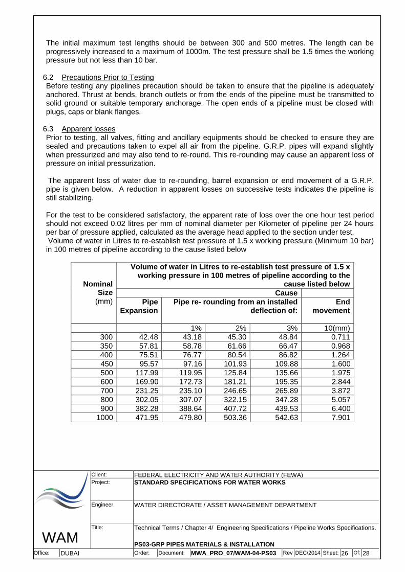
The initial maximum test lengths should be between 300 and 500 metres. The length can be progressively increased to a maximum of 1000m. The test pressure shall be 1.5 times the working pressure but not less than 10 bar.
6.2 Precautions Prior to Testing Before testing any pipelines precaution should be taken to ensure that the pipeline is adequately anchored. Thrust at bends, branch outlets or from the ends of the pipeline must be transmitted to solid ground or suitable temporary anchorage. The open ends of a pipeline must be closed with plugs, caps or blank flanges.
6.3 Apparent losses Prior to testing, all valves, fitting and ancillary equipments should be checked to ensure they are sealed and precautions taken to expel all air from the pipeline. G.R.P. pipes will expand slightly when pressurized and may also tend to re-round. This re-rounding may cause an apparent loss of pressure on initial pressurization.
The apparent loss of water due to re-rounding, barrel expansion or end movement of a G.R.P. pipe is given below. A reduction in apparent losses on successive tests indicates the pipeline is still stabilizing.
For the test to be considered satisfactory, the apparent rate of loss over the one hour test period should not exceed 0.02 litres per mm of nominal diameter per Kilometer of pipeline per 24 hours per bar of pressure applied, calculated as the average head applied to the section under test. Volume of water in Litres to re-establish test pressure of 1.5 x working pressure (Minimum 10 bar) in 100 metres of pipeline according to the cause listed below
Nominal Size
(mm)
Volume of water in Litres to re-establish test pressure of 1.5 x working pressure in 100 metres of pipeline according to the
cause listed below
Cause
Pipe Expansion
Pipe re- rounding from an installed deflection of:
End movement
1% 2% 3% 10(mm)
300 42.48 43.18 45.30 48.84 0.711
350 57.81 58.78 61.66 66.47 0.968
400 75.51 76.77 80.54 86.82 1.264
450 95.57 97.16 101.93 109.88 1.600
500 117.99 119.95 125.84 135.66 1.975
600 169.90 172.73 181.21 195.35 2.844
700 231.25 235.10 246.65 265.89 3.872
800 302.05 307.07 322.15 347.28 5.057
900 382.28 388.64 407.72 439.53 6.400
1000 471.95 479.80 503.36 542.63 7.901

WAM
Client: FEDERAL ELECTRICITY AND WATER AUTHORITY (FEWA) Project: STANDARD SPECIFICATIONS FOR WATER WORKS
Engineer WATER DIRECTORATE / ASSET MANAGEMENT DEPARTMENT
Title: Technical Terms / Chapter 4/ Engineering Specifications / Pipeline Works Specifications.
PS03-GRP PIPES MATERIALS & INSTALLATION
Office: DUBAI Order: Document: MWA_PRO_07/WAM-04-PS03 Rev:
DEC/20142
Sheet: 27 Of: 28
6.4 Repair Defects in pipes may be repaired by trained personnel only and shall be carried out according to the instruction and procedure as described in the manufacturer installation manual. Not more than one repair per pipe is acceptable and this repair shall extend over at least 50 mm of sound material on either side of the defect, but shall not extend over more than 7% of the length of the individual pipe spool. Repair by patching is not recommended.
6.5 Flushing and Disinfection Before the pipeline is placed in services, and before issue of the Provisional Taking Over Certificate by the FEWA, all pipelines shall be flushed and disinfected as per AWWA C651 or as directed by the FEWA. Pipelines shall be flushed with sufficiently high velocities to remove any sand or debris which has remained in the pipelines. The velocities shall not be less than 1.0 m/s. The time required for flushing shall be at least the time required to discharge three (3) times the contents of the pipeline section to be flushed.
Flushing water shall be discharged via temporary discharge lines into the sea or if feasible into road tankers. Any temporary connections required for flushing and washout shall be at the Contractor's cost, to be included in his unit rates for construction. All other materials, equipment and labour required for the flushing, disinfection operation and discharge of water shall also be furnished by the Contractor and included in his construction rates. Four (4) weeks before the Contractor intends to undertake flushing/disinfecting of all or part of the pipelines, the Contractor shall submit a detailed proposal also showing the quantity of water required. In general, FEWA has the water source, close to must off sites, for washing & sterilization, but the Contractor needs to fix a temporary meter for using this water near the water source and the tariff will be charged as per FEWA rules and regulations. However, if there is no FEWA water source nearby, or facing shortage in supply, then the Contractor should arrange the water for flushing by himself from the nearest available source and shall remain the property of the FEWA. The payment for this item shall be made as mentioned in the Schedule of Quantities and Rates.Pipeline should be sterilized by introducing water with a chlorine dose of 30 to 50 mg/I (30 to 50 ppm). After standing for 12 hours to 24 hours the water should be tested for residual chlorine to ensure that satisfactory sterilization has been achieved. Potable water may then be used to displace the chlorinated water, but the pipeline shall not be put into the service until bacteriological tests of water delivered at the end of the pipeline show that a satisfactory potable standard has been achieved. The pipeline shall be washed with potable water and commissioned at working pressure. The bacteriological tests shall be carried out only at the FEWA laboratory at Sharjah lab. Cost of tests / (and retests if required so) shall be borne by the Contractor. The cost of testing will be charged according to the prevailing FEWA rates and the Contractor shall include these in the relevant items of the schedules.
7. PACKING AND SHIPMENT
a) Offloading Care
Care must be taken when unloading and handling the pipes. Pipes must not be dropped on the ground. All pipes should be lifted at their mid-point; if this is not possible a spreader beam is required. A suitable textile sling or slings must be used. Pipes must not be lifted with chains, wire ropes etc.
WAM
Client: FEDERAL ELECTRICITY AND WATER AUTHORITY (FEWA) Project: STANDARD SPECIFICATIONS FOR WATER WORKS
Engineer WATER DIRECTORATE / ASSET MANAGEMENT DEPARTMENT
Title: Technical Terms / Chapter 4/ Engineering Specifications / Pipeline Works Specifications.
PS03-GRP PIPES MATERIALS & INSTALLATION
Office: DUBAI Order: Document: MWA_PRO_07/WAM-04-PS03 Rev:
DEC/20142
Sheet: 28 Of: 28
Unloading of specials Where a textile lifting strap has to be placed through the unit, care must be taken to avoid damaging or displacing the joint. Any displacement must be corrected. Units with branches must be lifted by the main pipe and not the branch.
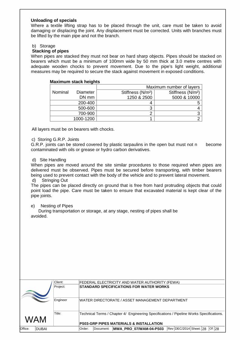
b) Storage Stacking of pipes
When pipes are stacked they must not bear on hard sharp objects. Pipes should be stacked on bearers which must be a minimum of 100mm wide by 50 mm thick at 3.0 metre centres with adequate wooden chocks to prevent movement. Due to the pipe's light weight, additional measures may be required to secure the stack against movement in exposed conditions.
Maximum stack heights
Nominal Diameter
DN mm
Maximum number of layers
Stiffness (N/m²) 1250 & 2500
Stiffness (N/m²) 5000 & 10000
200-400 4 5
500-600 3 4
700-900 2 3
1000-1200 1 2
All layers must be on bearers with chocks.
c) Storing G.R.P. Joints
G.R.P. joints can be stored covered by plastic tarpaulins in the open but must not n become contaminated with oils or grease or hydro carbon derivatives.
d) Site Handling When pipes are moved around the site similar procedures to those required when pipes are delivered must be observed. Pipes must be secured before transporting, with timber bearers being used to prevent contact with the body of the vehicle and to prevent lateral movement.
d) Stringing Out The pipes can be placed directly on ground that is free from hard protruding objects that could point load the pipe. Care must be taken to ensure that excavated material is kept clear of the pipe joints.
e) Nesting of Pipes During transportation or storage, at any stage, nesting of pipes shall be avoided.