monograph on rock mass classification systems and applications
TRANSCRIPT
Monograph
On
Rock Mass Classification Systems and Applications
2011
Hari Dev, Scientist ‘C’
S.K. Sharma, Chief Research Officer (Retd.) Publication-2
Central Soil and Materials Research Station, New Delhi
Monograph on Rock Mass Classification Systems and Applications
Monograph
On
Rock Mass Classification Systems and Applications
2011
By
Hari Dev, Scientist ‘C’
&
S.K. Sharma, Chief Research Officer (Retd.)
Central Soil and Materials Research Station Olof Palme Marg, Outer Ring Road, Hauz Khas, New Delhi-110016
Monograph on Rock Mass Classification Systems and Applications
i
FOREWORD
The Central Soil and Materials Research station (CSMRS), an attached office of the Ministry of
Water Resources, is a premier institute in the country at New Delhi which deals with field and
laboratory investigations, basic and applied research in problems on geomechanics, concrete
technology, construction materials and associated environment issues, having direct bearing on the
development of irrigation and power in the country and functions as an adviser and consultant in
the above fields to various projects and organisations in India and abroad.
So far in India, the excavation of large cavities has been restricted to underground power houses.
The first underground power house was constructed at Maithen for Damodar Valley Corporation,
way back in 1953, followed by Koyna in Maharashtra. Since then, a number of underground
excavations for hydropower development are in progress. Recently, road and rail tunnels have also
been successfully executed. Delhi Metro Rail Corporation (DMRC) bored tunnels with the help of
Tunnel Boring Machines (TBM). Rail link between Jammu and Srinagar has also become a reality
with many tunnels in between. Border Roads Organisation (BRO) has also taken up the task of
connecting the Lahaul and Spiti valley with Kullu-Manali through 9 km long all weather road
tunnel at Rohtang Pass to connect Leh and Ladakh area of Jammu and Kashmir. Scores of
underground excavations for hydropower development are either coming up or are in final stages of
execution.
Though lot of innovations have taken place in the field of rock engineering, still rock classification
and support systems are based on empirical calculations. The first engineering approach was
developed by the great genius Karl Terzaghi in 1946 followed by some other engineers. Deere gave
his concept of rock quality criteria on the basis of the drill core recovery. Later on, in 1970's some
development took place with the evolution of classification systems like Rock Structure Rating
(RSR) by Wickham, Rock Mass Rating (RMR) by Bieniawski and Q system by Nick Barton. RMR
and Q systems were immediately adopted by professionals working in the field of rock mechanics.
This monograph contains information about the developments in the field of rock classification
systems and their applications. Case studies of various underground structures viz. power houses
and water conveyance tunnels have also been included. The rock mass has been classified using
various classification methods. Support pressures have also been worked out. Attempt has been
made to compile the actual support systems adopted in underground excavations and correlate with
rock classification systems. Support pressures accommodated by the actual supports have also been
worked out. Observed support pressures for different projects from the instrumentation data have
been provided wherever available. Relative utilities of classification systems have been discussed.
This monograph is therefore informative and will be useful to the engineers and geologists working
in the field of rock mechanics dealing with underground structures in particular.
(Murari Ratnam)
Dated August 16, 2011 Director, CSMRS

Monograph on Rock Mass Classification Systems and Applications
ii
CONTENTS
Page No. 1. INTRODUCTION 1
2. UTILITIES OF ROCK MASS CLASSIFICATIONS 2
3. ROCK MASS CLASSIFICATION SYSTEMS 2
3.1. Terzaghi’s Rock Load Classification System 4
3.2. Classification System of Stini and Lauffer 7
3.3. Deere’s Rock Quality Designation (RQD) Classification System 8
3.3.1. Rock Quality Designation, RQD 8
3.4. Rock Structure Rating Classification System 11
3.5. Geomechanics Classification System of rock masses, Rock Mass Rating 14
(RMR)
3.6. NGI Tunnelling Quality Index Classification System or Q-System 21
3.6.1. Correlation between RMR and Q Values 28
4. APPLICATIONS OF ROCK MASS CLASSIFICATION SYSTEMS FOR 29
DESIGN OF SUPPORTS FOR UNDERGROUND EXCAVATIONS
4.1. Nathpa Jhakri H. E. Project, H.P. 30
4.1.1. Geology 30
4.1.2. Rock Mass Classification and Rock Pressures 30
4.1.3. Supports Actually Provided 31
4.2. Sardar Sarovar Project, Gujarat 32
4.2.1. Geology 32
4.2.2. Rock Mass Classification and Rock Pressures 33
4.2.3. Supports Actually Provided 33
4.3. Sanjay Vidyut Pariyojna, H.P. 35
4.3.1. Geology 35
4.3.2. Rock Mass Classification and Rock Pressures 35
4.3.3. Supports Actually Provided 35
4.4. Baspa H.E. Project, H.P. 36
4.4.1. Geology 36
4.4.2. Rock Mass Classification and Rock Pressures 37
4.4.3. Supports Actually Provided 37
4.5. Yamuna Hydroelectric Scheme Stage II (Chhibro Power House), Uttrakhand 37
4.5.1. Geology 37
4.5.2. Rock Mass Classification and Rock Pressure 38
4.5.3. Supports Actually Provided 38

Monograph on Rock Mass Classification Systems and Applications
iii
4.6. Lakhwar H.E. Project, Uttrakhand 40
4.6.1. Geology 40
4.6.2. Rock Mass Classification and Rock Pressures 40
4.6.3. Supports Actually Provided 40
4.7. Chamera H.E. Project, H.P. 43
4.7.1. Geology 43
4.7.2. Rock Mass Classification and Rock Pressures 43
4.7.3. Supports Actually Provided 44
4.8. Kadamparai Pumped Storage H.E. Project, Tamilnadu 45
4.8.1. Geology 45
4.8.2. Rock Mass Classification and Rock Pressures 45
4.8.3. Supports Actually Provided 45
4.9. Chukha H.E. Project, Bhutan 46
4.9.1. Geology 46
4.9.2. Rock Mass Classification and Rock Pressures 46
4.9.3. Supports Actually Provided 47
4.10. Tala H.E. Project, Bhutan 47
4.10.1. Power House 48
4.10.1.1 Geology 48
4.10.1.2 Rock Mass Classification and Rock Pressures 49
4.10.1.3 Supports Actually Provided 49
4.10.2 Head Race Tunnel 50
4.10.2.1 Geology 51
4.10.2.2 Rock Mass Classification and Rock Pressures 51
4.10.2.3 Supports Actually Provided 52
4.11. Ramganga Project Tunnels, U.P. 53
4.11.1. Geology 54
4.11.2. Rock Mass Classification and Rock Pressures 54
4.11.3. Supports Actually Provided 54
4.12. Narmada Sagar Project, M.P. 56
4.12.1. Geology 56
4.12.2. Rock Mass Classification and Rock Pressures 56
4.12.3. Supports Actually Provided 57
4.13. Giri Project Head Race Tunnel, H.P. 57
4.13.1. Geology 58
4.13.2. Rock Mass Classification and Rock Pressures 59
4.13.3. Supports Actually Provided 59
4.14. Uri Project, J & K 59
4.14.1. Geology 60
4.14.2. Rock Mass Classification and Rock Pressures 60
4.14.3. Supports Actually Provided 61

Monograph on Rock Mass Classification Systems and Applications
iv
4.15. Loktak H.E. Project, Manipur 61
4.15.1. Geology 61
4.15.2. Rock Mass Classification and Rock Pressures 63
4.15.3. Supports Actually Provided 63
4.16. Salal H.E. Project, J & K 63
4.16.1. Geology 64
4.16.2. Rock Mass Classification and Rock Pressures 65
4.16.3. Supports Actually Provided 65
4.17. Yamuna Hydroelectric Scheme, Stage II, Part I 65
4.17.1. Geology 66
4.17.2. Rock Mass Classification and Rock Pressures 67
4.17.3. Supports Actually Provided 67
4.18. Yamuna Hydroelectric Scheme, Stage II, Part II 67
4.18.1. Geology 67
4.18.2. Rock Mass Classification and Rock Pressures 68
4.18.3. Supports Actually Provided 68
4.19. Maneri Bhali Hydel Project, Stage I, U.P. 69
4.19.1. Geology 69
4.19.2. Rock Mass Classification and Rock Pressures 70
4.19.3. Supports Actually Provided 70
4.20. Khara Hydel Project, U.P. 71
4.20.1. Geology 71
4.20.2. Rock Mass Classification and Rock Pressures 72
4.20.3. Supports Actually Provided 72
4.21. Tehri Hydroelectric Project, U.P. 73
4.21.1. Geology 73
4.21.2. Rock Mass Classification and Rock Pressures 74
4.21.3. Supports Actually Provided 74
4.22. Bodhghat Hydel Project, M.P. 74
4.22.1. Geology 75
4.22.2. Rock Mass Classification and Rock Pressures 76
5. OBSERVED SUPPORT PRESSURES 77
6. COMPARISON OF ROCK CLASSIFICATION METHODS 78
RECOMMENDATIONS 79
REFERENCES 80
Monograph on Rock Mass Classification Systems and Applications
1
ROCK MASS CLASSIFICATION SYSTEMS AND APPLICATIONS
1.0 INTRODUCTION
In rock mechanics, the designer deals with complex rock masses and specific properties
of rock mass cannot be determined to meet design requirements. The forces resulting
from the redistribution of the virgin stresses existing before the excavation was made, are
more important than the applied loads in rock masses. An underground excavation is an
extremely complex structure and it is seldom possible, theoretically, to determine the
influence and interaction of various parameters (structural discontinuities, in-situ stresses
and weathering profile etc.) which control the stability of the excavation.
Analytical design methods utilize the analysis of stresses and deformations around
openings. They include such techniques as closed form solutions, numerical methods
(finite elements, finite difference and boundary elements etc.), analog simulations
(electrical and photo elastic) and physical modelling.
The design methods which are available for assessing the stability of underground
structures are analytical, observational and empirical methods i.e. to base the design on
precedent practice and experience.
Observational design methods rely on actual monitoring of ground movement during
excavation to detect measurable instability and on analysis of ground-support interaction.
Empirical design methods assess the stability by the use of statistical analysis of
underground observations. Engineering classifications of rock masses constitute the best
known empirical approach for assessing the stability of openings in rock. Empirical
design approach is recognized still as a primary approach to a wide range rock
engineering design problems. The continued reliance of the rock engineering designer on
this approach is a function of the difficulty in predicting or modelling the behaviour of a
complex system of fractured rock in response to, for example, the excavation of a large
cavern or series of caverns. Thus, all currently available forms of analysis generally
require the application of engineering judgement in one form or another and many
designers prefer to exercise this judgement via the recommendations of a rock mass
classification system rather than to apply their own judgement directly to the geological
data available to them.
Rock mass classifications have provided the systematic approach in an otherwise
haphazard trial and error procedure on many underground construction projects.
However, modern rock mass classifications have never been intended as the ultimate
solution to design problems, but only a device toward this end. Rock mass classifications
were developed to create some order out of the chaos in site investigation procedures and
to provide the desperately needed design approaches. They were not intended to replace
analytical studies, field observations and measurements.
Monograph on Rock Mass Classification Systems and Applications
2
There are various classifications of rock masses developed and adopted through out the
world. The aims and objectives of classifications along with description of the most
popular classifications, their merits and demerits and solution of a practical problem have
been presented in this monograph. Summaries of some important classification systems
are presented in this monograph, and although every attempt has been made to present all
of the pertinent data from original texts, there are numerous texts and comments which
can not be included. The interested reader should make every effort to read the cited
reference for a full appreciation of the use, applicability and limitations of each system.
2.0 UTILITIES OF ROCK MASS CLASSIFICATIONS
A rock mass classification system has the following utilities in an engineering application
(Bieniawski, 1989):
1. To divide a particular rock mass into groups of similar behaviour;
2. To provide a good basis for understanding the characteristics of each group;
3. To identify the most significant parameter influencing the behaviour of a rock mass;
4. To relate the experience of rock conditions at one site to the conditions and
experience encountered at other sites;
5. To facilitate the planning and design of structures in rock by yielding quantitative
data required for the solution of real engineering problems; and
6. To provide a common basis for communication among the engineering geologists,
rock mechanicians, design engineers and contractors.
These utilities can be fulfilled by ensuring that a classification system has the following
characteristics:
1. It is simple, easily remembered and understandable;
2. Each term is clear and the terminology used is widely accepted by engineers and
geologists;
3. The most significant properties of rock mass are included;
4. It is based on measurable parameters which can be determined by relevant tests
quickly and cheaply in the field;
5. It is based on rating system that can weigh the relative importance of the
classification parameters; and
6. It is functional by providing quantitative data for the design of rock support.
3.0 ROCK MASS CLASSIFICATION SYSTEMS
Rock mass classification schemes have been developing for over 100 years since Ritter
(1879) attempted to formalise an empirical approach to tunnel design, in particular for
determining support requirements. While the classification schemes are appropriate for
their original application, especially if used within the bounds of the case histories from
Monograph on Rock Mass Classification Systems and Applications
3
which they were developed, considerable caution must be exercised in applying rock
mass classification to other rock engineering problems.
Rock mass classifications have been successfully applied throughout the world: United
States (Deere et al., 1967; Wickham et al., 1972; Bieniawski, 1979), Canada (Coates,
1963; Franklin, 1975), Western Europe (Lauffer, 1958; Pacher et al., 1974; Barton et al.,
1974), South Africa (Bieniawski, 1973; Laubscher, 1977; Olivier, 1979), Australia
(Baczynski, 1980), New Zealand (Rutledge, 1978), Japan (Nakao, 1983), India (Ghose
and Raju, 1981), USSR (Protodyakonov, 1974), and in Poland (Kidybinski, 1979).
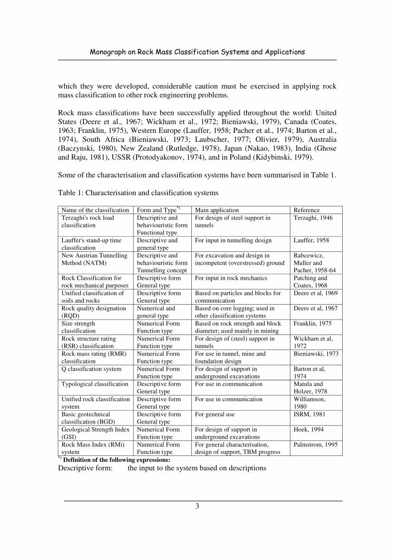
Some of the characterisation and classification systems have been summarised in Table 1.
Table 1: Characterisation and classification systems
Name of the classification Form and Type
*) Main application Reference
Terzaghi's rock load
classification
Descriptive and
behaviouristic form
Functional type
For design of steel support in
tunnels
Terzaghi, 1946
Lauffer's stand-up time
classification
Descriptive and
general type
For input in tunnelling design Lauffer, 1958
New Austrian Tunnelling
Method (NATM)
Descriptive and
behaviouristic form
Tunnelling concept
For excavation and design in
incompetent (overstressed) ground
Rabcewicz,
Muller and
Pacher, 1958-64
Rock Classification for
rock mechanical purposes
Descriptive form
General type
For input in rock mechanics Patching and
Coates, 1968
Unified classification of
soils and rocks
Descriptive form
General type
Based on particles and blocks for
communication
Deere et al, 1969
Rock quality designation
(RQD)
Numerical and
general type
Based on core logging; used in
other classification systems
Deere et al, 1967
Size strength
classification
Numerical Form
Function type
Based on rock strength and block
diameter; used mainly in mining
Franklin, 1975
Rock structure rating
(RSR) classification
Numerical Form
Function type
For design of (steel) support in
tunnels
Wickham et al,
1972
Rock mass rating (RMR)
classification
Numerical Form
Function type
For use in tunnel, mine and
foundation design
Bieniawski, 1973
Q classification system Numerical Form
Function type
For design of support in
underground excavations
Barton et al,
1974
Typological classification Descriptive form
General type
For use in communication Matula and
Holzer, 1978
Unified rock classification
system
Descriptive form
General type
For use in communication Williamson,
1980
Basic geotechnical
classification (BGD)
Descriptive form
General type
For general use ISRM, 1981
Geological Strength Index
(GSI)
Numerical Form
Function type
For design of support in
underground excavations
Hoek, 1994
Rock Mass Index (RMi)
system
Numerical Form
Function type
For general characterisation,
design of support, TBM progress
Palmstrom, 1995
*) Definition of the following expressions:
Descriptive form: the input to the system based on descriptions
Monograph on Rock Mass Classification Systems and Applications
4
Numerical form: the input parameters are given numerical ratings according to their
character
Behaviouristic form: the input is based on the behaviour of the rock mass in a tunnel
General type: the system is worked out to serve as a general characterisation
Functional type: the system is structured for a special application (for example for
rock support)
Of many rock mass classification systems in existence, six require special attention
because they are most common, namely Terzaghi (1946), Lauffer (1958), Deere et al.
(1967), Wickham et al. (1972), Bieniawski (1973), and Barton et al. (1974).
The concept of rock structure rating (RSR), developed in the United States by Wickham
et al. (1972,1974), was the first system featuring classification ratings for weighing the
relative importance of classification parameters. The Geo-mechanics Classification
(RMR System), proposed by Bieniawski (1973), and the Q-System, proposed by Barton
et al. (1974), were developed independently and both provide quantitative data for the
selection of modern tunnel reinforcement measures such as rock bolts and shotcrete.
The Q-system has been developed specifically for tunnels and chambers, whereas the
Geo-mechanics Classification, although also initially developed for tunnels, has been
applied to rock slopes and foundations, ground rippability assessment, and mining
problems (Laubscher, 1977; Ghose and Raju, 1981; Kendorski et al. 1983).
3.1 Terzaghi’s Rock Load Classification System
In 1946, Terzaghi proposed a simple rock classification system for use in estimating the
loads to be supported by steel arches in tunnels. He described various types of ground
and, based upon his experience in steel-supported rail and road tunnels in them Alps, he
assigned ranges of rock loads for various ground conditions.
Terzaghi stresses the importance of the geological survey which should be carried out
before a tunnel design is completed and particularly the importance of obtaining
information on the defects in the rock mass. To quote from his original classification:
“From an engineering point of view, knowledge of the type and intensity of the rock
defects may be much more important than the type of rock which will be encountered.
Therefore, during the survey, rock defects should receive special consideration. The
geological report should contain a detailed description of the observed defects in
geological terms. It should also contain a tentative classification of the defective rock in
the tunnel man’s terms, such as blocky and seamy, squeezing or swelling rock.”
He then defined these tunnelling terms as follows:
Intact rock contains neither joints nor hair cracks. Hence, if it breaks, it breaks across
sound rock. On account of the injury to the rock due to blasting, spalls may drop off the
roof several hours or days after blasting. This is known as a spalling condition. Hard,
Monograph on Rock Mass Classification Systems and Applications
5
intact rock may also be encountered in the popping condition involving the spontaneous
and violent detachment of rock slabs from the sides or roof.
Stratified rock consists of individual strata with little or no resistance against separation
along the boundaries between strata. The strata may or may not be weakened by
transverse joints. In such rock, the spalling condition is quite common.
Moderately jointed rock contains joints and hair cracks, but the blocks between joints
are locally grown together or so intimately interlocked that vertical walls do not require
lateral support. In rocks of this type, both spalling and popping conditions may be
encountered.
Blocky and seamy rock consists of chemically intact or almost intact rock fragments
which are entirely separated from each other and imperfectly interlocked. In such rock,
vertical walls may require lateral support.
Crushed but chemically intact rock has the character of a crusher run. If most or all of
the fragments are as small as fine sand grains and no recementation has taken place,
crushed rock below the water table exhibits the properties of water-bearing sand.
Squeezing rock slowly advances into the tunnel without perceptible volume increase. A
pre-requisite for squeeze is a high percentage of microscopic and sub-microscopic
particles of micaceous minerals or of clay minerals with a low swelling capacity.
Swelling rock advances into the tunnel chiefly on account of expansion. The capacity to
swell seems to be limited to those rocks which contain clay minerals such as
montmorillonite, with a high swelling capacity.
The rock load classification of Terzaghi (1946) was the first practical classification
system introduced and has been dominant in the United States for over 40 years, proving
very successful for tunnelling with steel supports.
A liner has to support the entire weight of overlying rock and soil only in extreme case of
shallow tunnel where the rock contains smooth vertical joints and where a little or no
horizontal stress acts to enhance friction. Stresses are redistributed around opening by
dilation and mobilization of strength along the joints in a mechanism known as arching
(Terzaghi 1946). The liner has to support only these stresses not carried by rock arch.
Terzaghi’s rock load concept has been explained in Fig. 1.
Terzaghi carried out numerous model tests using cohesion less sand to study the shape of
what he termed the “ground arch” above the tunnel. On the basis of these tests and on his
experience in steel –supported tunnels, he proposed the range of rock load values listed in
Table 2. The footnotes which accompanied this table in the original paper are included
for completeness. However, Cecil found that Terzaghi’s classification was too general to
permit an objective evaluation of rock quality and that it provides no quantitative

Monograph on Rock Mass Classification Systems and Applications
6
information on the properties of the rock mass. He recommended that its use be limited
to estimating rock loads for steel arch-supported tunnels.
Fig. 1: Terzaghi’s ground arch concept
Table 2 – Terzaghi’s rock load classification for steel arch-supported tunnels
{Rock load Hp in feet of rock on roof of support in tunnel with width B (feet) and height
Ht (feet) at a depth of more than 1.5 (B+Ht)*}
Rock condition Rock load Hp in feet Remarks
1. Hard and intact. Zero Light lining required only if
spalling or popping occurs
2. Hard stratified or
schistose**
.
0 to 0.25 B Light support, mainly for protection
against spalls.
Load may change erratically from
point to point. 3. Massive, moderately
jointed.
0 to 0.5 B
4. Moderately blocky and
seamy.
0.25 B to 0.35 (B+Ht) No side pressure
5. Very blocky and seamy 0.35 to 1.10(B+Ht) Little or no side pressure
6. Completely crushed but
chemically intact.
1.10(B+Ht) Considerable side pressure.
Softening effects of seepage
towards bottom of tunnel requires
either continuous support for lower
ends of ribs or circular ribs.
7. Squeezing rock, moderate
depth
1.10 to 2.10(B+Ht) Heavy side pressure, invert struts
required. Circular ribs are
recommended 8. Squeezing rock, great depth. 2.10 to 4.50(B+Ht)
9. Swelling rock Up to 250 feet,
irrespective of the value
of (B+Ht)
Circular ribs are required. In
extreme cases use yielding support.

Monograph on Rock Mass Classification Systems and Applications
7
*The roof of the tunnel is assumed to be located below the water table. If it is located
permanently above the water table, the values given for types 4 to 6 can be reduced by
fifty percent.
**Some of the most common rock formations contain layers of shale. In an unweathered
state, real shales are no worse than other stratified rocks. However, the term shale is often
applied to firmly compacted clay sediments which have not yet acquired the properties of
rock. Such so-called shale may behave in a tunnel like squeezing or even swelling rock.
If a rock formation consists of a sequence of horizontal layers of sandstone or limestone
and of immature shale, the excavation of the tunnel is commonly associated with a
gradual compression of the rock on both sides of the tunnel, involving a downward
movement of the roof. Furthermore, the relatively low resistance against slippage at the
boundaries between the so-called shale and the rock is likely to reduce very considerably
the capacity of the rock located above the roof to bridge. Hence, in such formations, the
roof pressure may be as in very blocky and seamy rock.
3.2 Classification System of Stini and Lauffer
Lauffer’s classification (1958) was based on the work of Stini (1950) and was a
considerable step forward in the art of tunnelling since it introduced the concept of stand-
up time of the active span in a tunnel, which is highly relevant in determining the type
and amount of tunnel support.
Lauffer suggested that the stand-up time for any given active span is related to the rock
mass characteristics in the manner illustrated in Fig. 2. Stand-up time is the length of time
which an underground opening will stand unsupported after excavation and barring down
while active span is the largest unsupported span in tunnel section between the face and
supports. In a tunnel, the unsupported span is defined as the span of the tunnel or the
distance between the face and the nearest support, if this is greater than the tunnel span.
Fig. 2: Relation between active span and stand-up time for different classes of rock mass
(After Lauffer 1958)

Monograph on Rock Mass Classification Systems and Applications
8
In this figure, the letters refer to the rock class. A is very good rock, corresponding to
Terzaghi’s hard and intact rock, while G is very poor rock which corresponds roughly to
Terzaghi’s squeezing or swelling rock.
Lauffer's original classification has since been modified by a number of authors, notably
Pacher et al (1974), and now forms part of the general tunnelling approach known as the
New Austrian Tunnelling Method (NATM).
3.3 Deere’s Rock Quality Designation (RQD) Classification System
The classification of Deere et al. (1967) introduced the rock quality designation (RQD)
index, which is a simple and practical method of describing the quality of rock core from
boreholes.
A proposal for providing uniform terminology for the description of joints was made by
Deere as given in Table 3.
Table 3: Descriptive terminology for joint spacing
Descriptive term Spacing of joints
English Metric
Very Close Less than 2 in Less than 5 cm
Close 2 in-1 ft 5 cm-30 cm
Moderately Close 1 ft-3 ft 30 cm-1 m
Wide 3 ft-10 ft 1 m-3 m
Very wide Greater than 10 ft Greater than 3 m
For RQD values greater than 60, they recommended support consisting of rock bolts,
mesh and strapping whereas for RQD values less than 40, steel sets or ribs were
specified. RQD values between 40 and 60, called for linear interpolation of support
requirements. RQD method is of interest as it can be used for the preliminary choice of
support as well as a constitutive parameter for more elaborate systems.
The following is general method of obtaining the quality of the rock at a site based on the
relative amount of fracturing and alteration.
3.3.1 Rock Quality Designation, RQD
The rock quality designation (RQD) is based on a modified core recovery procedure
which, in turn, is based indirectly on the number of fractures and the amount of softening
or alteration in the rock mass as observed in the rock cores from a drill hole.
Total length of core is summed up by counting only those pieces of core which are 10 cm
in length or longer and which are hard and sound. RQD is defined as the percentage of
intact core pieces longer than 100 mm (4 inches) in the total length of core. The core
Monograph on Rock Mass Classification Systems and Applications
9
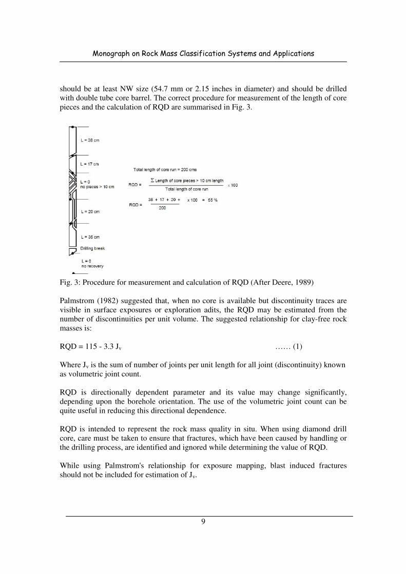
should be at least NW size (54.7 mm or 2.15 inches in diameter) and should be drilled
with double tube core barrel. The correct procedure for measurement of the length of core
pieces and the calculation of RQD are summarised in Fig. 3.
Fig. 3: Procedure for measurement and calculation of RQD (After Deere, 1989)
Palmstrom (1982) suggested that, when no core is available but discontinuity traces are
visible in surface exposures or exploration adits, the RQD may be estimated from the
number of discontinuities per unit volume. The suggested relationship for clay-free rock
masses is:
RQD = 115 - 3.3 Jv …… (1)
Where Jv is the sum of number of joints per unit length for all joint (discontinuity) known
as volumetric joint count.
RQD is directionally dependent parameter and its value may change significantly,
depending upon the borehole orientation. The use of the volumetric joint count can be
quite useful in reducing this directional dependence.
RQD is intended to represent the rock mass quality in situ. When using diamond drill
core, care must be taken to ensure that fractures, which have been caused by handling or
the drilling process, are identified and ignored while determining the value of RQD.
While using Palmstrom's relationship for exposure mapping, blast induced fractures
should not be included for estimation of Jv.

Monograph on Rock Mass Classification Systems and Applications
10
It has been found that there is a reasonably good relation between the numerical values of
the RQD and general quality of the rock for engineering purposes. Table 4 can be
referred for Deere's rock classification and support requirements for tunnels.
Table 4: Support recommendations for tunnels in rock (6-12 m in diameter), Deere 1969
Rock
Quality
Tunnelling
Method
Alternate Support System
Steel Setsa Rock Bolts
b Shotcrete
c
Excellanta
RQD>90
A Boring
Machine
None to occasional light set
Rock load 0 to 0.2Bd
None to
occasional
None to occasional
local application
B. Conventional None to occasional light set
Rock load 0 to 0.3B
None to
occasional
None to occasional
local application 50 to
75 mm
Gooda
75<RQD<90
A Boring
Machine
Occasional light sets to
pattern on 1.5 to 1.8 m
centre. Rock load 0 to 0.4B
Occasional to
pattern 1.5 to
1.8 m centre.
None to occasional
local application 50 to
75 mm
B. Conventional Light sets at 1.5 to 1.8 m
centre, Rock load 0.3 to
0.6B
Pattern 1.5 to
1.8 m centre
Occasional local
application 50 to 75
mm
Fair
50<RQD<75
A Boring
Machine
Light to medium sets, 1.5 to
1.8 m centre, Rock load 0.4
to 1.0B
Pattern 1.5 to
1.8 m centre
50 to 100 mm on crown
B. Conventional Light to medium sets, 1.5 to
1.8 m centre, Rock load 0.4
to 1.3B
Pattern 1.5 to
1.8 m centre
100 mm or more in
crown and sides
Poorb
75<RQD<90
A Boring
Machine
Medium circular sets on 0.9
to 1.2 m centre, Rock load
1.0 to 1.6B
Pattern 1.5 to
1.8 m centre
100 mm to 150 mm on
crown and sides,
combine with bolts.
B. Conventional Medium to heavy sets on
0.6 to 1.2 m centre, Rock
load 1.3 to 2.0B
Pattern 1.5 to
1.8 m centre
150 or more on crown
and sides, combine with
bolts
Very Poorb
RQD<25
(Excluding
squeezing or
swelling
grounds)
A Boring
Machine
Medium to heavy circular
sets on 0.6 centre, Rock
load 1.6 to 2.2B
Pattern 0.6 to
1.2 m centre
150 mm or more on
whole section, combine
with medium sets.
B. Conventional Heavy circular sets on 0.6
centre, Rock load 2.0 to
2.8B
Pattern 0.9 m
centre
150 mm or more on
whole section, combine
medium to heavy sets.
Very Poorb
RQD<25
(Squeezing
and
swelling)
A Boring
Machine
Very heavy circular sets on
0.6 m centre. Rock load
upto 75 m.
Pattern 0.6 to
0.9 m
150 mm or more on
whole section, combine
with heavy sets.
B. Conventional Very heavy circular sets on
2 foot m centre. Rock load
upto 75 m.
Pattern 0.6 to
0.9 m
150 mm or more on
whole section, combine
with heavy sets. a In good and excellent rock, the support requirement in general be minimal but will be
dependent on joint geometry, tunnel diameter and relative orientation of joints and
tunnel. b Lagging requirements will usually be zero in excellent rock and will range from upto
25% in good rock to 100% in very good rock. c Mesh requirement usually will be zero in excellent rock and will range from
occasional mesh (or straps) in good rock to 100% mesh in very poor rock. d B = width of tunnel in m.

Monograph on Rock Mass Classification Systems and Applications
11
Deere's RQD was widely used, particularly in North America, after its introduction.
Deere and Deere (1972), Meritt (1972) and Deere and Deere (1988) attempted to relate
RQD to Terzaghi's rock load factors and to rock bolt requirements in tunnels. The most
important use of RQD is as a component of the RMR and Q classifications.
3.4 Rock Structure Rating Classification System
The Rock Structure Rating (RSR) concept developed in the USA by Wickham, Tideman
and Skinner presents a quantitative method for describing the quality of a rock mass for
selecting the appropriate ground support (Tables 5, 6 and 7). It was the first complete
rock mass classification system proposed after being introduced by Terzaghi in 1946. The
main contribution of the RSR concept was that it introduced a rating system for rock
masses and classification system gives both input and output.
The RSR concept considered two general categories of factors influencing rock mass
behaviour in tunnelling; geological parameters and construction parameters. These
parameters grouped as A, B, & C are explained as follows:
Parameter A (General appraisal of rock structure) includes:
• Rock type origin ( igneous, sedimentary or metamorphic)
• Rock hardness (Hard, Medium, Soft, Decomposed)
• Geological Structure (Massive, slightly faulted/folded, moderately faulted/folded,
intensely faulted/folded)
Parameter B (Effect of discontinuity pattern with respect to the direction of tunnel drive)
includes:
• Joint spacing
• Joint orientation (strike & dip)
• Direction of tunnel drive
Parameter C (Effect of groundwater inflow) includes:
• Overall rock mass quality due to parameters A & B combined
• Joint condition (good, fair)
• Amount of water inflow
Table 5: Rock structure rating-parameter A, geological condition
*Basic
Rock Type
Massive
RQD>75
Slightly
folded or faulted
RQD 50-75
Moderately folded
or faulted
RQD 25-50
Intensely
folded or faulted
RQD<25
Type I 30 22 15 9
Type II 27 20 13 8
Type III 24 18 12 7
Type IV 17 15 10 6

Monograph on Rock Mass Classification Systems and Applications
12
*Basic Rock Type
Basic Rock Rock Condition
Hard Medium Soft Decomposed
Igneous I II III IV
Metamorphic I II III IV
Sedimentary II III IV IV
Table 6: Rock structure rating-parameter B, joint spacing condition
Average Joint
Spacing
Strike Perpendicular to Axis Strike parallel to Axis
Direction of Drive Direction of Drive
Both With Dip Against Dip Both
Dip of Prominent Joints Dip of Prominent Joints
Flat Dipping Vertical Dipping Vertical Flat Dipping Vertical
Very closely
Jointed< 2’’
9 11 13 10 12 9 9 7
Closely Jointed
2’’-6
’’ 13 16 19 15 17 14 14 11
Moderately
Jointed 6’’-1’
23 24 28 19 22 23 23 19
Moderate to
Blocky 1’-2
’ 30 32 36 25 28 30 28 24
Blocky to
Massive 2’-4’ 36 38 40 33 35 36 34 28
Massive > 4’ 40 43 45 37 40 40 38 34
Flat 0°-20° Dipping 20°-50° Vertical 50°-90°
Table 7: Rock structure rating-parameter C, ground water joint condition
Anticipated water inflow
Gallons/min/1 m
Sum of Parameters A & B
13-44 45-75
Joint condition
Good Fair Poor Good Fair Poor
None 22 18 12 25 22 18
Slight< 200 gpm 19 15 9 23 19 14
Moderate 200-1000 gpm 15 11 7 21 16 12
Heavy >1000 gpm 10 8 6 18 14 10
Good-Tight or cemented, Fair-Slightly weathered, Poor-Severely weathered or open
The RSR value of any tunnel section is obtained by summing the weighted numerical
values determined for each parameter. This reflects the quality rock mass with respect to
its need for support. Since a lesser amount of support was expected for machine bored
tunnels than those excavated by drill and blast methods, it was suggested that RSR values
be adjusted for machine bored tunnels.

Monograph on Rock Mass Classification Systems and Applications
13
Note that the RSR classification used Imperial units and that these units have been
retained in this discussion.
Three tables from Wickham et al's 1972 paper can be used to evaluate the rating of each
of these parameters to arrive at the RSR value (maximum 100).
For example, a hard metamorphic rock which is slightly folded or faulted has a rating of
A = 22 (from Table 5). The rock mass is moderately jointed, with joints striking
perpendicular to the tunnel axis which is being driven east-west, and dipping at between
20o to 50
o.
Table 6 gives the rating for B = 24 for driving with dip. (defined below)
The values of A + B = 46 and this means that, for joints of fair condition (slightly
weathered and altered) and a moderate water inflow of between 200 and 1000 gallons per
minute, Table 7 gives the rating for C = 16. Hence, the final value of the rock structure
rating RSR = A + B + C = 62.
A typical set of curves for a 24 foot diameter tunnel are given in Fig. 4 which shows that,
for the RSR value of 62 derived above, the predicted support would be 2 inches of
shotcrete and 1 inch diameter rock bolts spaced at 5 foot centres. As indicated in the
figure, steel sets would be spaced at more than 7 feet apart and would not be considered a
practical solution for the support of this tunnel.
Fig. 4: RSR support estimates for a 24 ft. (7.3 m) diameter circular tunnel. Note that rock
bolts and shotcrete are generally used together. (After Wickham et al 1972)

Monograph on Rock Mass Classification Systems and Applications
14
For the same size tunnel in a rock mass with RSR = 30, the support could be provided by
8 WF 31 steel sets (8 inch deep wide flange I section weighing 31 lb per foot) spaced 3
feet apart, or by 5 inches of shotcrete and 1 inch diameter rock bolts spaced at 2.5 feet
centres. In this case it is probable that the steel sets solution would be cheaper and more
effective than the use of rock bolts and shotcrete.
Although, the RSR classification system is not widely used today, Wickham et al's work
played a significant role in the development of the classification schemes discussed in the
following pages.
3.5 Geomechanics Classification System of Rock Masses, Rock Mass Rating (RMR)
Bieniawski (1974) developed a rock mass rating system based on the following five
parameters:
1) Uniaxial compressive strength of intact rock,
2) Rock quality designation,
3) Spacing of joints,
4) Condition of discontinuities, and
5) Ground water conditions.
In addition, the strike and dip orientations of joints were removed from the list of basic
classification parameters and their effects allowed for by a rating adjustment made after
the basic parameters had been considered. RMR rating on the basis of various influencing
parameters is given in Table 8. The Effect of Joint Strike and Dip Orientations in
Tunnelling have been presented in Table 9. Average stand-up time of underground
openings of various sizes with varying rock classes and the effect of joint strike and dip
orientation in tunnelling are given in Tables 10 and 11.
He assigned numerical rating values to all these parameters. The rock mass rating is the
summation of the individual ratings of the five parameters and correction for orientation
of joints made after the basic parameters had been considered. Based on the value of the
rock mass rating designated as RMR value, Bieniawski divides the whole universe of
rock mass into five classes, I through V. The five basic classification parameters are:
1. Strength of intact rock material
Bieniawski uses the classification of the uniaxial compressive strength of intact rock
proposed by Deere and Miller. Alternatively, for all but very low strength rocks the point
load index may be used as a measure of intact rock material strength.
2. Rock Quality Designation
Deere’s RQD is used as a measure of drill core quality.
Monograph on Rock Mass Classification Systems and Applications
15
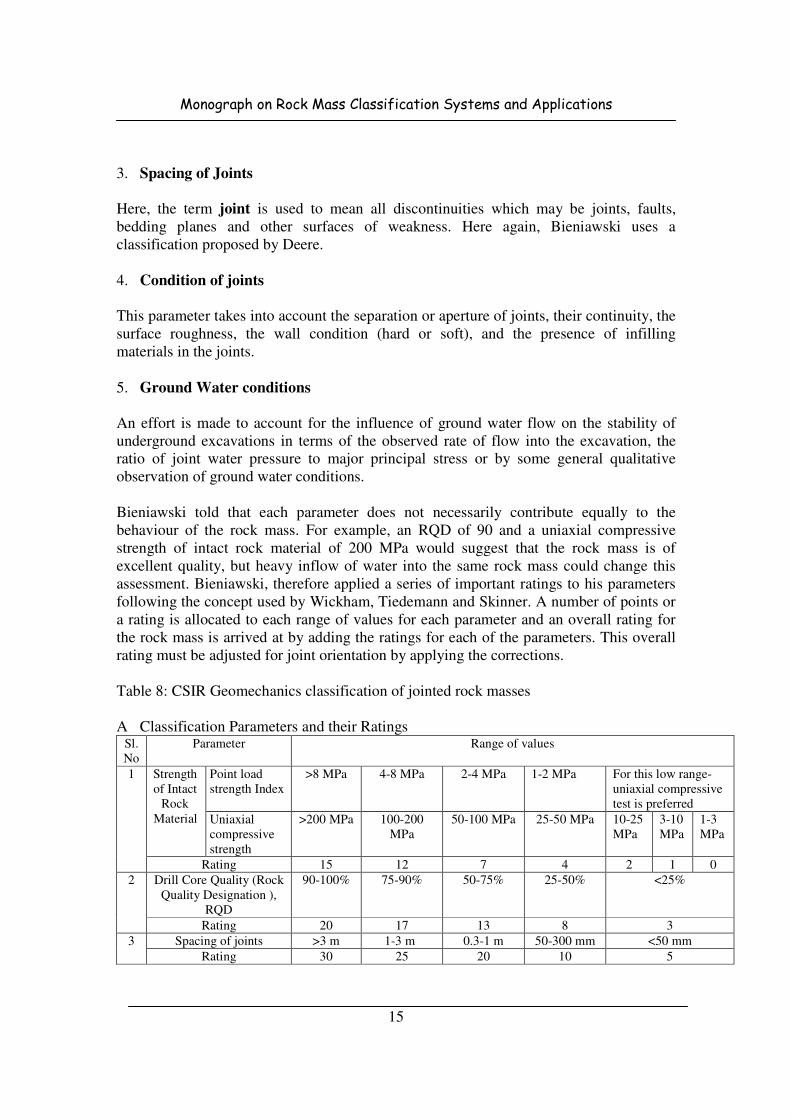
3. Spacing of Joints
Here, the term joint is used to mean all discontinuities which may be joints, faults,
bedding planes and other surfaces of weakness. Here again, Bieniawski uses a
classification proposed by Deere.
4. Condition of joints
This parameter takes into account the separation or aperture of joints, their continuity, the
surface roughness, the wall condition (hard or soft), and the presence of infilling
materials in the joints.
5. Ground Water conditions
An effort is made to account for the influence of ground water flow on the stability of
underground excavations in terms of the observed rate of flow into the excavation, the
ratio of joint water pressure to major principal stress or by some general qualitative
observation of ground water conditions.
Bieniawski told that each parameter does not necessarily contribute equally to the
behaviour of the rock mass. For example, an RQD of 90 and a uniaxial compressive
strength of intact rock material of 200 MPa would suggest that the rock mass is of
excellent quality, but heavy inflow of water into the same rock mass could change this
assessment. Bieniawski, therefore applied a series of important ratings to his parameters
following the concept used by Wickham, Tiedemann and Skinner. A number of points or
a rating is allocated to each range of values for each parameter and an overall rating for
the rock mass is arrived at by adding the ratings for each of the parameters. This overall
rating must be adjusted for joint orientation by applying the corrections.
Table 8: CSIR Geomechanics classification of jointed rock masses
A Classification Parameters and their Ratings Sl.
No
Parameter Range of values
1 Strength
of Intact
Rock
Material
Point load
strength Index
>8 MPa 4-8 MPa 2-4 MPa 1-2 MPa For this low range-
uniaxial compressive
test is preferred
Uniaxial
compressive
strength
>200 MPa 100-200
MPa
50-100 MPa 25-50 MPa 10-25
MPa
3-10
MPa
1-3
MPa
Rating 15 12 7 4 2 1 0
2 Drill Core Quality (Rock
Quality Designation ),
RQD
90-100% 75-90% 50-75% 25-50% <25%
Rating 20 17 13 8 3
3 Spacing of joints >3 m 1-3 m 0.3-1 m 50-300 mm <50 mm
Rating 30 25 20 10 5

Monograph on Rock Mass Classification Systems and Applications
16
4 Condition of joints Very rough
surfaces
Not
continuous
No
separation
Hard joint
wall rock
Slightly rough
surfaces
Separation
< 1m
Hard joint
wall rock
Slightly rough
surfaces
Separation
< 1mm
Soft joint wall
rock
Slickensided
surfaces or
Gouge< 5mm
thick or joints
open 1-5 mm
Continuous
joints
Soft gouge >5mm
thick or Joints open >
5mm
Continuous joints
Rating 25 20 12 6 0
5. Ground
water
Inflow per
10 m
tunnel
length
None
OR
<25
liters/min
25-125
liters/min
>125 liters/min
Ratio of
Joint
water
pressure
to
major
principal
stress
0
OR
0.0-0.2
OR
0.2-0.5
OR
>0.5
General
conditions
Completely
dry
Moist only
(interstitial
water)
Water under
moderate
pressure
Severe water
problems
Rating 10 7 4 0
B Rating adjustment for joint orientations Strike and dip
orientations of joints
Very
favourable
Favourable Fair Unfavourable Very
unfavourable
Ratings Tunnels 0 -2 -5 -10 -12
Foundations 0 -2 -7 -15 -25
Slopes 0 -5 -25 -50 -60
C Rock mass classes determined from total ratings Rating 100-81 80-61 60-41 40-21 <20
Class No I II III IV V
Description Very good
rock
Good rock Fair rock Poor rock Very poor
rock
D Meaning of rock mass classes Class No. I II III IV V
Average
stand-up time
10 years for
5m span
6 months for
4m span
1 week for 3
m span
5hours for
15m span
10m in. for
0.5m span
Cohesion of
the rock mass
>300kPa 200-300kPa 150-200kPa 100-150kPa <100kPa
Friction
angle of the
rock mass
>45° 40°-45° 35°-40° 30°-35° <30°

Monograph on Rock Mass Classification Systems and Applications
17
Table 9: Effect of joint strike and dip orientations in tunnelling
Strike perpendicular to tunnel axis Strike parallel to tunnel axis Dip
0°-20°
irrespective
of strike
Drive with dip Drive against dip
Dip 45°-
90°
Dip
20°-45°
Dip
45°-90°
Dip 20°-45° Dip 45°-90
° Dip
20°-45
°
Favourable Fair Unfavourable Very unfavourable Fair Unfavourable
Table 10: Stand-up time of underground openings
Rock Class I II III IV V
Unsupported
Span, m
5 4 3 1.5 0.5
Average
Stand-Up
Times
10 Years 6 Months 1 Week 5 Hours 10 Minutes
Table 11: The effect of joint strike and dip orientation in tunnelling
Strike Perpendicular to Tunnel Axis Strike Parallel to Tunnel
Axis Drive With Dip Drive Against Dip
Dip Dip Dip Dip Dip Dip
45o-90o 20o -45o 45o -90o 20o -45o 45o -90o 20o -45o
Very
Favourable
Favourable Fair Unfavourable Very
Favourable
Fair
Dipo 0
oto 20
o: Unfavourable, irrespective of strike
To apply the geo-mechanics classification, the rock mass along the tunnel route is divided
into a number of structural regions, i.e. zones in which certain geological features are
more or less uniform within each region. The above six classification parameters are
determined for each structural region from measurements in the field and entered into the
standard input data sheet.
The first five parameters are grouped into five ranges of values. Since the various
parameters are not equally important for the overall classification of a rock mass,
important ratings are allocated to the different value ranges of the parameters, a higher
rating indicating better rock mass conditions.
Once the classification parameters are determined, the important ratings are assigned to
each parameter. In this respect, the typical rather than the worst conditions are evaluated.
Furthermore, it should be noted that the important ratings, which are given for
discontinuity spacings, apply to rock masses having three sets of discontinuities. Thus,
when only two sets of discontinuities are present, a conservative assessment is obtained.

Monograph on Rock Mass Classification Systems and Applications
18
After the important ratings of the classification parameters are established, the ratings for
the five parameters are summed to yield the basic rock mass rating for the structural
region under consideration.
At this stage, the influence of the strike and dip of discontinuities is included by adjusting
the basic rock mass rating. This step is treated separately because the influence of
discontinuity orientation depends upon engineering application, e.g. tunnel (mine), slope,
or foundation. It will be noted that the ‘value’ of the parameter ‘discontinuity orientation’
is not given in quantitative terms but by quantitative descriptions such as ‘favourable’. To
facilitate a decision whether strike and dip orientations are favourable or not, reference
should be made to studies by Wickham et al. (1972). In the case of civil engineering
projects, an adjustment for discontinuity orientations will suffice. For mining
applications, other adjustments may be called for such as the stress at depth or a change
in stress.
After the adjustment for discontinuity orientations, the rock mass is classified and
grouped in the final (adjusted) rock mass ratings (RMR) into five rock mass classes, the
full range of the possible RMR values varying from 0 to 100. Note that the rock mass
classes are in groups of twenty ratings each.
A tunnel is to be driven through slightly weathered granite with a dominant joint set
dipping at 60o against the direction of the drive. Index testing and logging of diamond
drilled core give typical Point-load strength index values of 8 MPa and average RQD
values of 70%. The slightly rough and slightly weathered joints with a separation of <1
mm are spaced at 300 mm. Tunnelling conditions are anticipated to be wet. The RMR
value for the example under consideration is determined as follows:
Table Item Value Rating
5, A.1 Point load index 8 MPa 12
5, A.2 RQD 70% 13
5, A.3 Spacing of
discontinuities
300 mm 10
5, E.4 Condition of
discontinuities
Note 1 22
5, A.5 Ground water Wet 7
5, B Adjustment for joint
orientation
Note 2 -5
Total 59
Note 1: For slightly rough and altered discontinuity surfaces with a separation of <1 mm,
Table 5.A.4 gives a rating of 25. When more detailed information is available, Table 5.E
can be used to obtain a more refined rating. Hence, in this case, the rating is the sum of: 4
(1-3 m discontinuity length), 4 (separation 0.1-1.0 mm), 3 (slightly rough), 6 (no filling)
and 5 (slightly weathered0 = 22

Monograph on Rock Mass Classification Systems and Applications
19
Note 2. Table 5.F gives a description of 'Fair' for the conditions assumed where the tunnel
is to be driven against the dip of a set of joints dipping at 60o. Using this description for
'Tunnels and Mines' in Table 5.B gives an adjustment rating of -5.
The value of 59 indicates that the rock mass is on the boundary between the 'Fair rock'
and 'Good rock' categories.
In the case of tunnels and chambers, the output from the Geo-mechanics Classification is
the stand up time and the maximum stable rock span for a given rock mass ratings.
Bieniawski has related his rock mass rating (or total rating score for the rock mass) to the
stand-up time of an active unsupported span as originally proposed by Lauffer. Average
stand-up time v/s unsupported span is shown in Fig. 5.
Fig 5: Average Stand-up time v/s Unsupported Span
Support load can be determined from the Geomechanics classification as:
P= {(100-RMR)/100}γB} …… (2)
Where, P is the support load, RMR is the rock mass ratings; and γ is the density of the
rock Kg/m3.
The Geomechanics Classification provides guidelines for the selection of roof support to
ensure long-term stability of various rock mass classes. These guidelines depend on such

Monograph on Rock Mass Classification Systems and Applications
20
factors as the depth below surface (in-situ stress), tunnel size and shape, and the method
of excavation.
Bieniawski (1989) published a set of guidelines for the selection of support in tunnels in
rock for which the value of RMR has been determined. The guidelines are reproduced in
Table 12.
Table 12: Guidelines for excavation and support of 10 m span rock tunnels in accordance
with the RMR system (After Bieniawski 1989)
Rock mass
class
Excavation Rock bolts (20 mm
diameter, fully
grouted)
Shotcrete Steel sets
I-Very good
rock
RMR: 81-100
Full face
3 m advance
Generally no support required except spot bolting
II- Good rock
RMR: 61-80
Full face
1-1.5 m advance. Complete
support 20 m from face
Locally, bolts in
crown 3 m long,
spaced 2.5 m with
occasional wire
mesh
50 mm in
crown where
required
None
III- Fair rock
RMR: 41-60
Top heading and bench
1.5-3 m advance in top
heading
Commence support after
blast
Complete support 10 m
from heading
Systematic bolts 4
m long, spaced
1.5-2 m in crown
and walls with
wire mesh in
crown.
50-100 mm
in crown and
30 mm in
sides
None
IV- Poor rock
RMR: 21-40
Top heading and bench
1.0-1.5 m advance in top
heading
Install support concurrently
with excavation, 10 m from
face
Systematic bolts 4-
5 m long, spaced
1-1.5 m in crown
and walls with
wire mesh.
100-150 mm
in crown and
100 mm in
sides
Light to medium
ribs spaced 1.5 m,
where required
V- Very poor
rock
RMR: <20
Multiple drifts 0.5-1.5 m
advance in top heading.
Install support concurrently
with excavation. Shotcrete
as soon as possible after
blasting.
Systematic bolts 5-
6 m long, spaced
1-1.5 m in crown
and walls with
wire mesh. Bolt
invert
150-200 mm
in crown,
150 mm in
sides and 50
mm face.
Medium to heavy
ribs spaced 0.75
m with steel
lagging and
forepoling if
required. Close
invert.
Table 12 has not had any major revision, hence in mining and civil engineering
applications, steel fibre reinforced shotcrete (SFRS) may be considered in place of wire
mesh and shotcrete.
The Geomechanics Classification is also applicable to rock foundation and slopes. This is
a useful feature that can assist with the design of slopes near the tunnel portals as well as
allow estimates of deformability of foundations for such structures as bridges and dams.
Monograph on Rock Mass Classification Systems and Applications
21
In the case of rock foundation, the following correlation was obtained:
Em = 2xRMR – 100 …… (3)
Where Em is the in-situ modulus of deformation in GPa and RMR> 50.
Most recently, Serafim and Pereira (1983) provided many results in the range RMR< 50
and proposed a new correlation:
Em = 10[(RMR-10)/40]
…… (4)
Hoek and Brown (1980) proposed a method for estimating rock mass strength which also
makes use of RMR classification. The RMR system is very simple to use and the
classification parameters are easily obtained from either drill hole data or underground
mapping. This classification is applicable and adaptable to many different situations
including coal mining, hard rock mining, slope stability, foundation stability and
tunnelling.
The output from the RMR classification method tends to be rather conservative, which
can lead to overdesign of support system (Beiniawski 1989). This aspect is best overcome
by monitoring rock behaviour during tunnel construction and adjusting RMR ratings to
local conditions. An example of this approach is the work of Kaiser et al. (1986), who
found that the no support limit was too conservative and proposed the following
correction to adjust RMR (no support) at the no support limit for opening size effect:
RM (NS) = 22 ln ED + 25 …… (5)
Where ED is the equivalent dimension as defined by Barton et al. (1974).
3.6 NGI Tunnelling Quality Index Classification System or Q-System
The Q–system of rock mass classification was developed in Norway by Barton, Lien and
Lunde (1974), all of the Norwegian Geotechnical Institute (NGI). Its development
represented a major contribution to the subject of rock mass classification for a number of
reasons; the system was proposed on the basis of an analysis of some 212 tunnel case
histories from Scandinavia. It is quantitative classification system, and it is an
engineering system enabling the design of tunnel supports.
The Q-system is based on a numerical assessment of the rock mass quality using six
different parameters:
Block Sizes
!. Rock Quality Designation (RQD);
2. Number of joint sets;
Monograph on Rock Mass Classification Systems and Applications
22
Shear Strength
3. Roughness of the most unfavourable joint or discontinuity;
4. Degree of alteration or filling along the weakest joint;
Active Stresses 5. Water inflow; and
6. Stress condition.
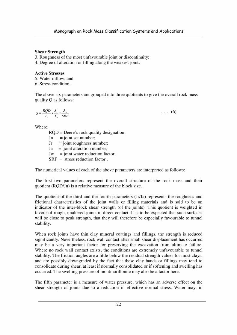
The above six parameters are grouped into three quotients to give the overall rock mass
quality Q as follows:
SRF
Jx
J
Jx
J
RQDQ w
a
r
n
= …… (6)
Where,
RQD = Deere’s rock quality designation;
Jn = joint set number;
Jr = joint roughness number;
Ja = joint alteration number;
Jw = joint water reduction factor;
SRF = stress reduction factor .
The numerical values of each of the above parameters are interpreted as follows:
The first two parameters represent the overall structure of the rock mass and their
quotient (RQD/Jn) is a relative measure of the block size.
The quotient of the third and the fourth parameters (Jr/Ja) represents the roughness and
frictional characteristics of the joint walls or filling materials and is said to be an
indicator of the inter-block shear strength (of the joints). This quotient is weighted in
favour of rough, unaltered joints in direct contact. It is to be expected that such surfaces
will be close to peak strength, that they will therefore be especially favourable to tunnel
stability.
When rock joints have thin clay mineral coatings and fillings, the strength is reduced
significantly. Nevertheless, rock wall contact after small shear displacement has occurred
may be a very important factor for preserving the excavation from ultimate failure.
Where no rock wall contact exists, the conditions are extremely unfavourable to tunnel
stability. The friction angles are a little below the residual strength values for most clays,
and are possibly downgraded by the fact that these clay bands or fillings may tend to
consolidate during shear, at least if normally consolidated or if softening and swelling has
occurred. The swelling pressure of montmorillonite may also be a factor here.
The fifth parameter is a measure of water pressure, which has an adverse effect on the
shear strength of joints due to a reduction in effective normal stress. Water may, in
Monograph on Rock Mass Classification Systems and Applications
23
addition, cause softening and possible outwash in the case of clay-filled joints. The sixth
parameter is a measure of: a) loosening load in the case of shear zones and clay bearing
rock b) rock stress in competent rock, and c) squeezing and swelling loads in plastic
incompetent rock. The sixth parameter is regarded as the ‘total stress’ parameter. The
quotient of the fifth and sixth parameters (Jw/SRF) is a complicated empirical factor
describing the ‘active stresses’.
Barton et al. (1974) consider the parameters, Jn, Jr and Ja as playing a more important
role than joint orientation, and if joint orientation had been included, the classification
would have been less general. However, orientation is implicit in parameters, Jr and Ja
because they apply to the most unfavourable joints.
Q values ranges from 0.001 to 1000 as per modified Q charts. The Q value is related to
tunnel support requirements by defining the equivalent dimension (ED), which is a
function of both the size and the purpose of the excavation, is obtained by dividing the
span, diameter, or the wall height of the excavation by a quantity called the excavation
support ratio (ESR), thus:
ED = (Excavation Span, Diameter or Height (m))/ESR (7)
The ESR is related to the use for which the excavation is intended and the degree of
safety demanded as shown below.
Excavation Category ESR No. of cases
A. Temporary mine openings 3-5 2
B. Vertical shafts:
Circular section 2.5 --
rectangular/square section 2.0 --
C. Permanent mine openings, 1.6 83
D. Storage rooms, water treatment 1.3 25
Plants, minor highway and rail road tunnels,
Surge chambers access tunnels.
E. Power stations, major highway rail /road 1.0 73
Tunnels, civil/defence chambers, portals,
Intersections.
F. Underground nuclear power stations 0.8 2
The relationship between the index Q and the equivalent dimensions (ED) of an
excavation determines the appropriate support measures. Barton et al. (1974) provide 38
support categories which give estimates of permanent support. For temporary support
determination either Q is increased to 5Q or ESR is increased to 1.5 ESR. For selection of
the support measures using the Q-system, the reader should consult the original paper.
The maximum span (unsupported) =2(ESR) Q0.4
…… (8)

Monograph on Rock Mass Classification Systems and Applications
24
The classification of individual parameters used to obtain the Tunnelling Index Q for a
rock mass has been given in Table 13.
Table 13: Q-logging ratings for RQD, Jn , Jr , Ja , Jw and SRF (Barton, 2002)
1. Rock Quality Designation RQD (%)
A Very poor 0-25
B Poor 25-50
C Fair 50-75
D Good 75-90
E Excellent 90-100
Notes: i) Where RQD is reported or measured as ≤ 10 (including 0), a nominal value of 10 is used
to evaluate Q.
ii) RQD intervals of 5, i.e., 100, 95, 90, etc., are sufficiently accurate.
2. Joint set number Jn
A Massive, no or few joints 0.5-1
B One joint set 2
C One joint set plus random joints 3
D Two joint sets 4
E Two joint sets plus random joints 6
F Three joint sets 9
G Three joint sets plus random joints 12
H Four or more joint sets, random, heavily jointed, ‘sugar-cube’, etc. 15
J Crushed rock, earthlike 20
Notes i) For tunnel intersections, use (3.0 × Jn).
ii) For portals use (2.0 × Jn).
3. Joint roughness number Jr
a) Rock-wall contact, and b) Rock-wall contact before 10 cm shear
A Discontinuous joints 4
B Rough or irregular, undulating 3
C Smooth, undulating 2 D Slickensided, undulating 1.5
E Rough or irregular, planar 1.5
F Smooth, planar 1.0
G Slickensided, planar 0.5
Notes: i) Descriptions refer to small-scale features and intermediate scale features, in that order.
b) No rock-wall contact when sheared
H Zone containing clay minerals thick enough to prevent rock-wall contact.
1.0
J Sandy, gravely or crushed zone thick enough to prevent rock-wall contact
1.0
Notes: ii) Add 1.0 if the mean spacing of the relevant joint set is greater than 3 m.
Monograph on Rock Mass Classification Systems and Applications
25
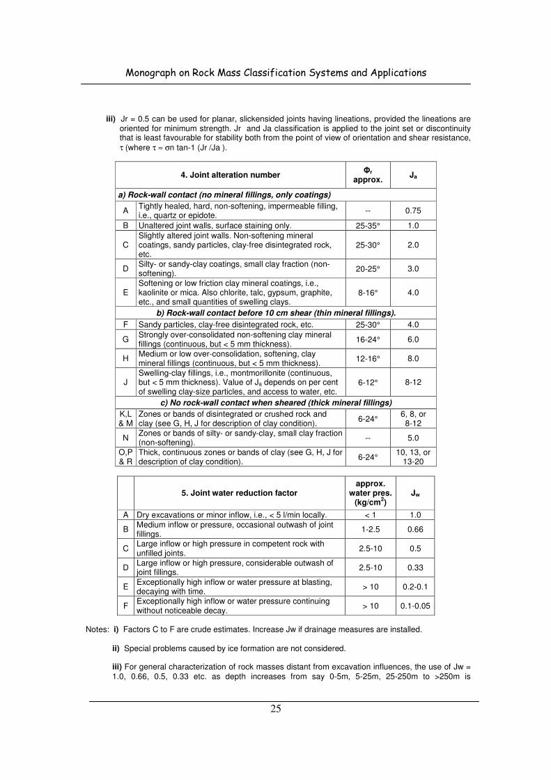
iii) Jr = 0.5 can be used for planar, slickensided joints having lineations, provided the lineations are oriented for minimum strength. Jr and Ja classification is applied to the joint set or discontinuity that is least favourable for stability both from the point of view of orientation and shear resistance,
τ (where τ ≈ σn tan-1 (Jr /Ja ).
4. Joint alteration number Φr
approx. Ja
a) Rock-wall contact (no mineral fillings, only coatings)
A Tightly healed, hard, non-softening, impermeable filling, i.e., quartz or epidote.
-- 0.75
B Unaltered joint walls, surface staining only. 25-35° 1.0
C Slightly altered joint walls. Non-softening mineral coatings, sandy particles, clay-free disintegrated rock, etc.
25-30° 2.0
D Silty- or sandy-clay coatings, small clay fraction (non-softening).
20-25° 3.0
E Softening or low friction clay mineral coatings, i.e., kaolinite or mica. Also chlorite, talc, gypsum, graphite, etc., and small quantities of swelling clays.
8-16° 4.0
b) Rock-wall contact before 10 cm shear (thin mineral fillings).
F Sandy particles, clay-free disintegrated rock, etc. 25-30° 4.0
G Strongly over-consolidated non-softening clay mineral fillings (continuous, but < 5 mm thickness).
16-24° 6.0
H Medium or low over-consolidation, softening, clay mineral fillings (continuous, but < 5 mm thickness).
12-16° 8.0
J Swelling-clay fillings, i.e., montmorillonite (continuous, but < 5 mm thickness). Value of Ja depends on per cent of swelling clay-size particles, and access to water, etc.
6-12° 8-12
c) No rock-wall contact when sheared (thick mineral fillings)
K,L& M
Zones or bands of disintegrated or crushed rock and clay (see G, H, J for description of clay condition).
6-24° 6, 8, or 8-12
N Zones or bands of silty- or sandy-clay, small clay fraction (non-softening).
-- 5.0
O,P & R
Thick, continuous zones or bands of clay (see G, H, J for description of clay condition).
6-24° 10, 13, or
13-20
5. Joint water reduction factor approx.
water pres. (kg/cm
2)
Jw
A Dry excavations or minor inflow, i.e., < 5 l/min locally. < 1 1.0
B Medium inflow or pressure, occasional outwash of joint fillings.
1-2.5 0.66
C Large inflow or high pressure in competent rock with unfilled joints.
2.5-10 0.5
D Large inflow or high pressure, considerable outwash of joint fillings.
2.5-10 0.33
E Exceptionally high inflow or water pressure at blasting, decaying with time.
> 10 0.2-0.1
F Exceptionally high inflow or water pressure continuing without noticeable decay.
> 10 0.1-0.05
Notes: i) Factors C to F are crude estimates. Increase Jw if drainage measures are installed.
ii) Special problems caused by ice formation are not considered. iii) For general characterization of rock masses distant from excavation influences, the use of Jw = 1.0, 0.66, 0.5, 0.33 etc. as depth increases from say 0-5m, 5-25m, 25-250m to >250m is

Monograph on Rock Mass Classification Systems and Applications
26
recommended, assuming that RQD /Jn is low enough (e.g. 0.5-25) for good hydraulic connectivity. This will help to adjust Q for some of the effective stress and water softening effects, in combination with appropriate characterization values of SRF. Correlations with depth-dependent static deformation modulus and seismic velocity will then follow the practice used when these were developed.
6. Stress Reduction Factor SRF
a) Weakness zones intersecting excavation, which may cause loosening of rock mass when tunnel is excavated
A Multiple occurrences of weakness zones containing clay or chemically disintegrated rock, very loose surrounding rock (any depth).
10
B Single weakness zones containing clay or chemically disintegrated
rock (depth of excavation ≤ 50 m). 5
C Single weakness zones containing clay or chemically disintegrated rock (depth of excavation > 50 m).
2.5
D Multiple shear zones in competent rock (clay-free), loose surrounding rock (any depth).
7.5
E Single shear zones in competent rock (clay-free), (depth of excavation
≤ 50 m). 5.0
F Single shear zones in competent rock (clay-free), (depth of excavation > 50 m).
2.5
G Loose, open joints, heavily jointed or ‘sugar cube’, etc. (any depth) 5.0 Notes: i) Reduce these values of SRF by 25-50% if the relevant shear zones only influence but do not
intersect the excavation. This will also be relevant for characterization.
b) Competent rock, rock stress problems σσσσc /σσσσ1 σσσσφ /σσσσc SRF
H Low stress, near surface, open joints. > 200 < 0.01 2.5
J Medium stress, favourable stress condition. 200-10 0.01-0.3 1
K High stress, very tight structure. Usually favourable to stability, may be unfavourable for wall stability.
10-5 0.3-0.4 0.5-2
L Moderate slabbing after > 1 hour in massive rock. 5-3 0.5-0.65 5-50
M Slabbing and rock burst after a few minutes in massive rock.
3-2 0.65-1 50-200
N Heavy rock burst (strain-burst) and immediate dynamic deformations in massive rock.
< 2 > 1 200-400
Notes: ii) For strongly anisotropic virgin stress field (if measured): When 5 ≤ σ1 /σ3 ≤ 10, reduce σc to
0.75 σc. When σ1 /σ3 > 10, reduce σc to 0.5 σc, where σc = unconfined compression strength,
σ1 and σ3 are the major and minor principal stresses, and σθ = maximum tangential stress (estimated from elastic theory).
iii) Few case records available where depth of crown below surface is less than span width.
Suggest an SRF increase from 2.5 to 5 for such cases (see H). iv) Cases L, M, and N are usually most relevant for support design of deep tunnel excavations in
hard massive rock masses, with RQD /Jn ratios from about 50 to 200. v) For general characterization of rock masses distant from excavation influences, the use of
SRF = 5, 2.5, 1.0, and 0.5 is recommended as depth increases from say 0-5m, 5-25m, 25-250m to >250m. This will help to adjust Q for some of the effective stress effects, in combination with appropriate characterization values of Jw. Correlations with depth - dependent static deformation modulus and seismic velocity will then follow the practice used when these were developed.
Monograph on Rock Mass Classification Systems and Applications
27
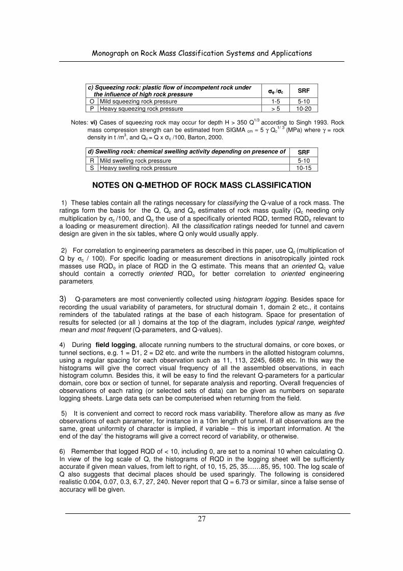
c) Squeezing rock: plastic flow of incompetent rock under the influence of high rock pressure
σσσσφ /σσσσc SRF
O Mild squeezing rock pressure 1-5 5-10
P Heavy squeezing rock pressure > 5 10-20 Notes: vi) Cases of squeezing rock may occur for depth H > 350 Q
1/3 according to Singh 1993. Rock
mass compression strength can be estimated from SIGMA cm ≈ 5 γ Qc1/ 3
(MPa) where γ = rock
density in t /m3, and Qc = Q x σc /100, Barton, 2000.
d) Swelling rock: chemical swelling activity depending on presence of water
SRF
R Mild swelling rock pressure 5-10
S Heavy swelling rock pressure 10-15
NOTES ON Q-METHOD OF ROCK MASS CLASSIFICATION 1) These tables contain all the ratings necessary for classifying the Q-value of a rock mass. The ratings form the basis for the Q, Qc and Qo estimates of rock mass quality (Qc needing only
multiplication by σc /100, and Qo the use of a specifically oriented RQD, termed RQDo relevant to a loading or measurement direction). All the classification ratings needed for tunnel and cavern design are given in the six tables, where Q only would usually apply.
2) For correlation to engineering parameters as described in this paper, use Qc (multiplication of
Q by σc / 100). For specific loading or measurement directions in anisotropically jointed rock masses use RQDo in place of RQD in the Q estimate. This means that an oriented Qc value should contain a correctly oriented RQDo for better correlation to oriented engineering parameters.
3) Q-parameters are most conveniently collected using histogram logging. Besides space for
recording the usual variability of parameters, for structural domain 1, domain 2 etc., it contains reminders of the tabulated ratings at the base of each histogram. Space for presentation of results for selected (or all ) domains at the top of the diagram, includes typical range, weighted mean and most frequent (Q-parameters, and Q-values). 4) During field logging, allocate running numbers to the structural domains, or core boxes, or
tunnel sections, e.g. 1 = D1, 2 = D2 etc. and write the numbers in the allotted histogram columns, using a regular spacing for each observation such as 11, 113, 2245, 6689 etc. In this way the histograms will give the correct visual frequency of all the assembled observations, in each histogram column. Besides this, it will be easy to find the relevant Q-parameters for a particular domain, core box or section of tunnel, for separate analysis and reporting. Overall frequencies of observations of each rating (or selected sets of data) can be given as numbers on separate logging sheets. Large data sets can be computerised when returning from the field. 5) It is convenient and correct to record rock mass variability. Therefore allow as many as five observations of each parameter, for instance in a 10m length of tunnel. If all observations are the same, great uniformity of character is implied, if variable – this is important information. At ‘the end of the day’ the histograms will give a correct record of variability, or otherwise. 6) Remember that logged RQD of < 10, including 0, are set to a nominal 10 when calculating Q. In view of the log scale of Q, the histograms of RQD in the logging sheet will be sufficiently accurate if given mean values, from left to right, of 10, 15, 25, 35……85, 95, 100. The log scale of Q also suggests that decimal places should be used sparingly. The following is considered realistic 0.004, 0.07, 0.3, 6.7, 27, 240. Never report that Q = 6.73 or similar, since a false sense of accuracy will be given.
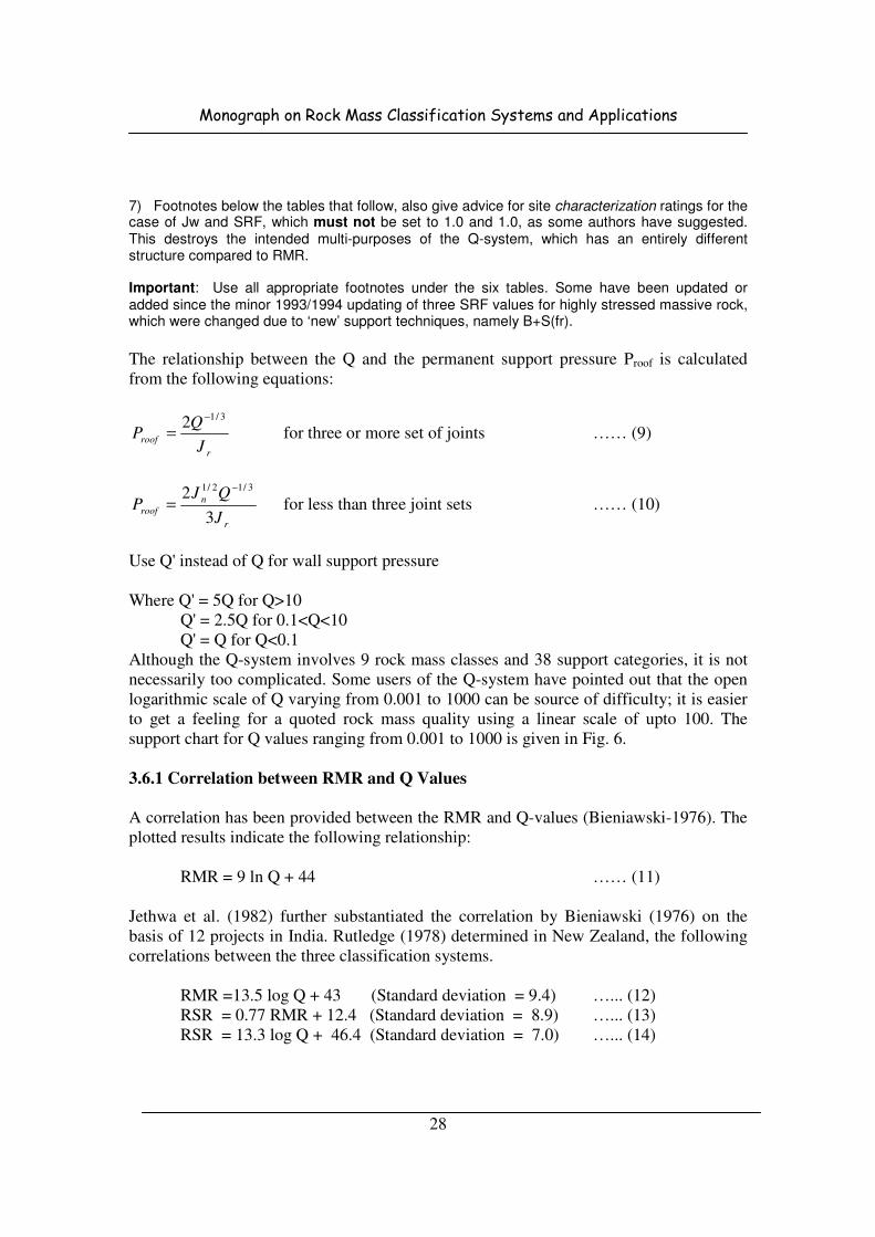
Monograph on Rock Mass Classification Systems and Applications
28
7) Footnotes below the tables that follow, also give advice for site characterization ratings for the case of Jw and SRF, which must not be set to 1.0 and 1.0, as some authors have suggested. This destroys the intended multi-purposes of the Q-system, which has an entirely different structure compared to RMR. Important: Use all appropriate footnotes under the six tables. Some have been updated or added since the minor 1993/1994 updating of three SRF values for highly stressed massive rock, which were changed due to ‘new’ support techniques, namely B+S(fr).
The relationship between the Q and the permanent support pressure Proof is calculated
from the following equations:
r
roofJ
QP
3/12 −
= for three or more set of joints …… (9)
r
n
roofJ
QJP
3
2 3/12/1 −
= for less than three joint sets …… (10)
Use Q' instead of Q for wall support pressure
Where Q' = 5Q for Q>10
Q' = 2.5Q for 0.1<Q<10
Q' = Q for Q<0.1
Although the Q-system involves 9 rock mass classes and 38 support categories, it is not
necessarily too complicated. Some users of the Q-system have pointed out that the open
logarithmic scale of Q varying from 0.001 to 1000 can be source of difficulty; it is easier
to get a feeling for a quoted rock mass quality using a linear scale of upto 100. The
support chart for Q values ranging from 0.001 to 1000 is given in Fig. 6.
3.6.1 Correlation between RMR and Q Values
A correlation has been provided between the RMR and Q-values (Bieniawski-1976). The
plotted results indicate the following relationship:
RMR = 9 ln Q + 44 …… (11)
Jethwa et al. (1982) further substantiated the correlation by Bieniawski (1976) on the
basis of 12 projects in India. Rutledge (1978) determined in New Zealand, the following
correlations between the three classification systems.
RMR =13.5 log Q + 43 (Standard deviation = 9.4) …... (12)
RSR = 0.77 RMR + 12.4 (Standard deviation = 8.9) …... (13)
RSR = 13.3 log Q + 46.4 (Standard deviation = 7.0) …... (14)
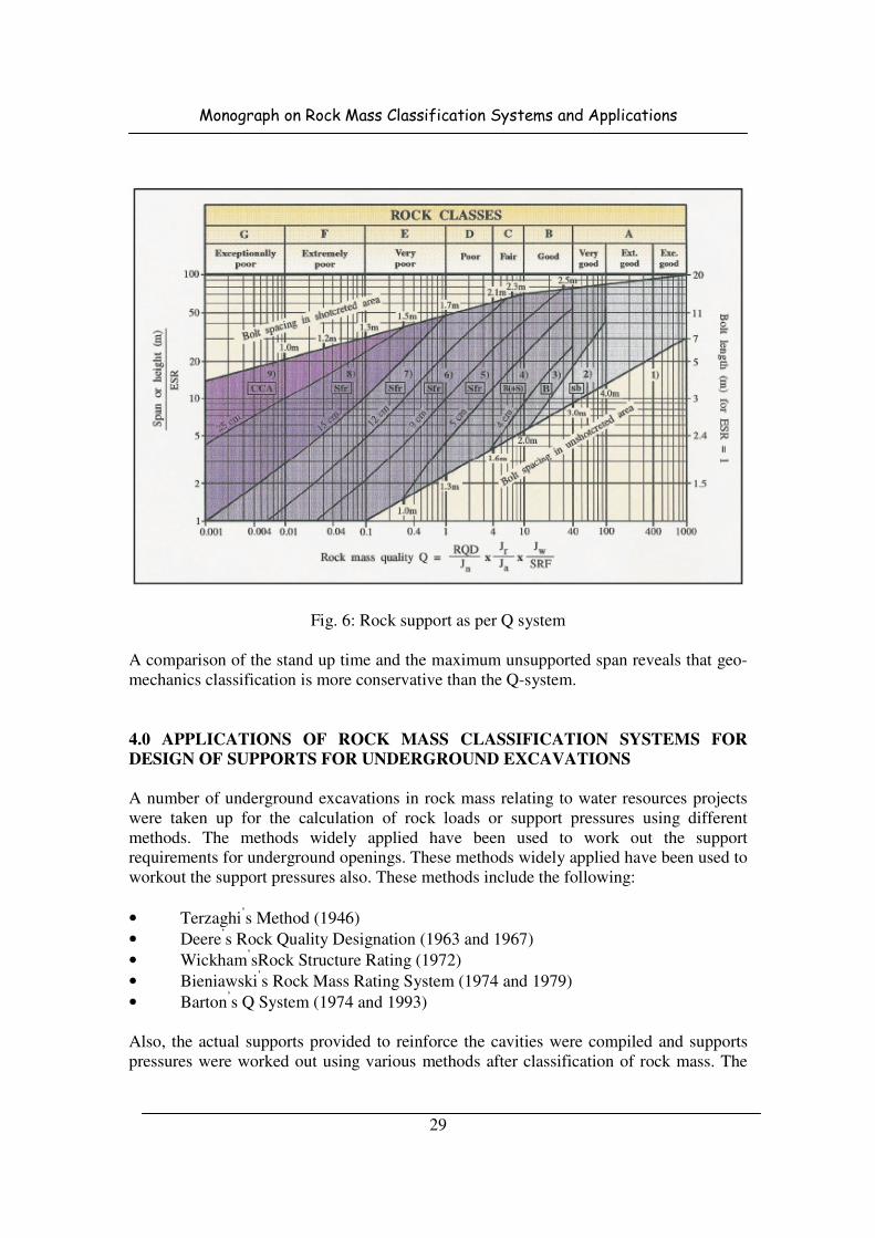
Monograph on Rock Mass Classification Systems and Applications
29
Fig. 6: Rock support as per Q system
A comparison of the stand up time and the maximum unsupported span reveals that geo-
mechanics classification is more conservative than the Q-system.
4.0 APPLICATIONS OF ROCK MASS CLASSIFICATION SYSTEMS FOR
DESIGN OF SUPPORTS FOR UNDERGROUND EXCAVATIONS
A number of underground excavations in rock mass relating to water resources projects
were taken up for the calculation of rock loads or support pressures using different
methods. The methods widely applied have been used to work out the support
requirements for underground openings. These methods widely applied have been used to
workout the support pressures also. These methods include the following:
• Terzaghi’s Method (1946)
• Deere’s Rock Quality Designation (1963 and 1967)
• Wickham’sRock Structure Rating (1972)
• Bieniawski’s Rock Mass Rating System (1974 and 1979)
• Barton’s Q System (1974 and 1993)
Also, the actual supports provided to reinforce the cavities were compiled and supports
pressures were worked out using various methods after classification of rock mass. The

Monograph on Rock Mass Classification Systems and Applications
30
observed support pressures in various underground structures were also collected for
comparison with accommodated support pressures.
4.1 Nathpa Jhakri H. E. Project, H.P.
Nathpa Jhakri H.E. Project envisages the utilization of about 488 m drop in river Sutlej
between Nathpa and Jhakri in Himachal Pradesh on the Indo-Tibet National Highway
about 150 km from Shimla. The fully underground project consists of concrete gravity
dam, four underground desilting chambers, 10.15 m diameter and 27.3 km long head race
tunnel, 301 m deep underground surge tank, three pressure shafts, underground
powerhouse 222 m (L) x 20 m (W) x 49 m (H), an underground transformer hall and
10.15 m diameter and 960 m long tail race tunnel with a downstream surge gallery.
4.1.1 Geology
The pre-cambrian rocks belong to the Wangtu-Jeory Gneissic Complex in the eastern
margin of Rampur window. They are surrounded by Jutog series of carbonaceous slates,
limestones, quartzites and schist separated by Main Central Thrust (MCT) which is
prominent and well known shear zone in the Himalayan region. The weaker rocks
(mainly schists) are folded with more than two generations of folds and are intersected by
steeply dipping faults and shear zones.
The area encompassing the power house site contains essentially quartz –mica schist.
These rocks are moderately jointed and at places slightly to moderately weathered. Rocks
are intruded by quartzite veins of varying thickness often forming boundaries which
follow the foliation trend. Geological map of Nathpa Jhakri Project is shown in Fig. 7.
4.1.2 Rock Mass Classification and Rock Pressures
Depending upon the geological and engineering properties of the rock, RMR and RSR
have been calculated. The rock loads have been presented in Table 14. For details of
tunnel supports refer Bhasin et. al. (1996a).
Table 14: Rock class and support pressures at Nathpa Jhakri Power House
Method of Rock Classification Rock Type : Quartz Mica schist
Rock Class by Terzaghi
Support Pr. (kg/cm2)
Massive Moderately Jointed (Class 4)
1.35 to 6.5
Wickham’s RSR
Support Pr. (kg/cm2)
52
5.07
Bieniawski’s RMR
Support Pr. (kg/cm2)
60 (Fair)
2.16
Barton’s Q value
Support Pr. (kg/cm2), Proof
Pwall
2.7 (Fair)
0.42
0.31
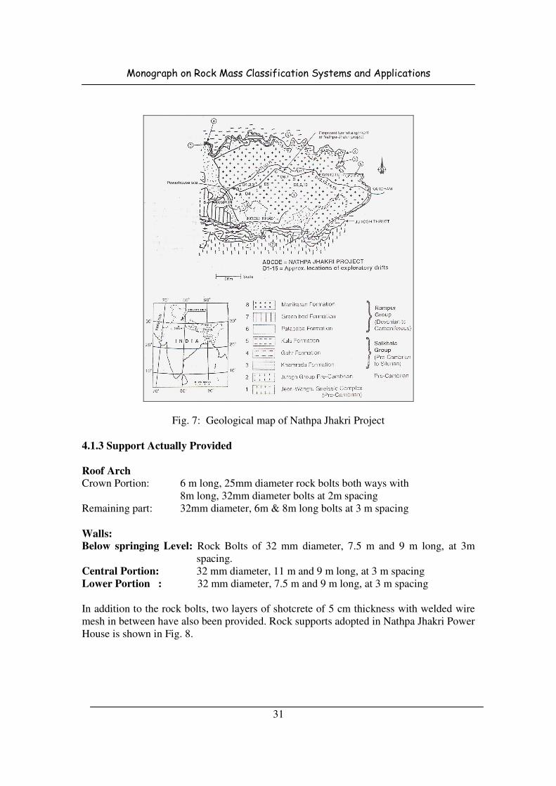
Monograph on Rock Mass Classification Systems and Applications
31
Fig. 7: Geological map of Nathpa Jhakri Project
4.1.3 Support Actually Provided
Roof Arch
Crown Portion: 6 m long, 25mm diameter rock bolts both ways with
8m long, 32mm diameter bolts at 2m spacing
Remaining part: 32mm diameter, 6m & 8m long bolts at 3 m spacing
Walls:
Below springing Level: Rock Bolts of 32 mm diameter, 7.5 m and 9 m long, at 3m
spacing.
Central Portion: 32 mm diameter, 11 m and 9 m long, at 3 m spacing
Lower Portion : 32 mm diameter, 7.5 m and 9 m long, at 3 m spacing
In addition to the rock bolts, two layers of shotcrete of 5 cm thickness with welded wire
mesh in between have also been provided. Rock supports adopted in Nathpa Jhakri Power
House is shown in Fig. 8.
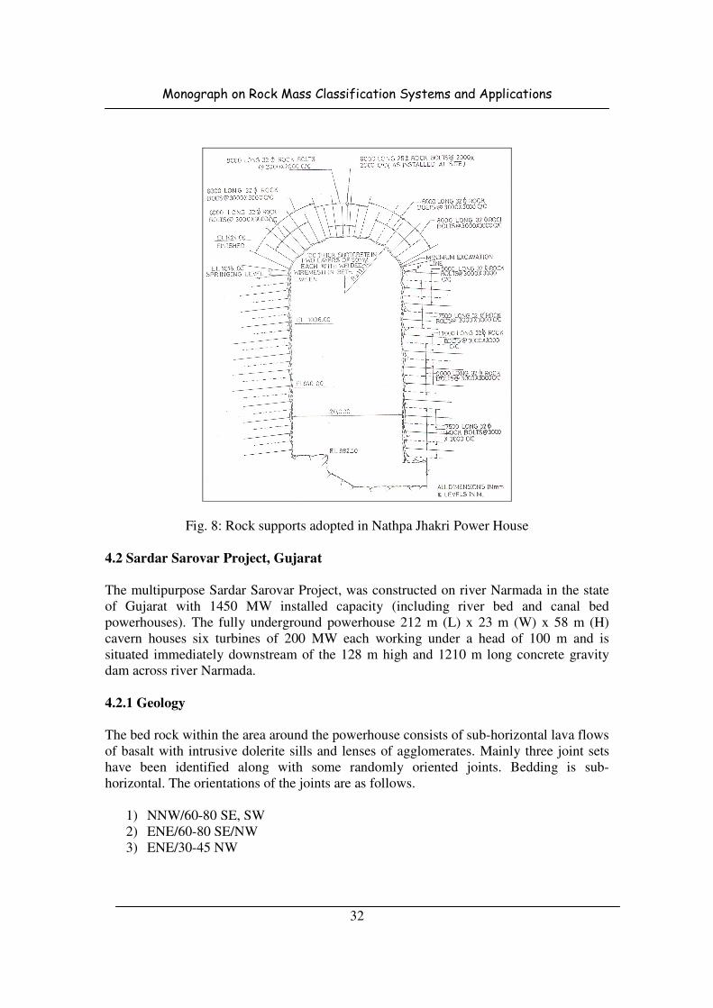
Monograph on Rock Mass Classification Systems and Applications
32
Fig. 8: Rock supports adopted in Nathpa Jhakri Power House
4.2 Sardar Sarovar Project, Gujarat
The multipurpose Sardar Sarovar Project, was constructed on river Narmada in the state
of Gujarat with 1450 MW installed capacity (including river bed and canal bed
powerhouses). The fully underground powerhouse 212 m (L) x 23 m (W) x 58 m (H)
cavern houses six turbines of 200 MW each working under a head of 100 m and is
situated immediately downstream of the 128 m high and 1210 m long concrete gravity
dam across river Narmada.
4.2.1 Geology
The bed rock within the area around the powerhouse consists of sub-horizontal lava flows
of basalt with intrusive dolerite sills and lenses of agglomerates. Mainly three joint sets
have been identified along with some randomly oriented joints. Bedding is sub-
horizontal. The orientations of the joints are as follows.
1) NNW/60-80 SE, SW
2) ENE/60-80 SE/NW
3) ENE/30-45 NW

Monograph on Rock Mass Classification Systems and Applications
33
Joints striking ENE have been found to contain thin fillings of calcite and chlorite. In
general the joints can be described as having a rough surface, very narrow aperture and
having medium persistence. These Characteristics have been found to be favourable for
constructing a cavern of such dimension.
A shear zone of 1 to 2 m wide dipping 60
o to 65
o south was noticed across the cavern
along the contact of a dolerite dyke at the southern end. It consists of rock fragments of
dolerite with little clay and is calcified. The porphyritic basalt which covers 85% of the
cavern roof is traversed by two shear zone 0.1 to 0.8 m thick running across the cavern
roof.
4.2.2 Rock Mass classification and Rock Pressures
The rock pressures have been presented in Table 15.
Table 15: Rock class and support pressures at Sardar Sarovar Power House
Method of rock
classification
Rock Type
Basalt Dolerite Sheared rock mass
Rock Class By
Terzaghi
Support Pr., kg/cm2
Very Blocky &
Seamy, Class 4
Very Blocky &
Seamy, Class 4
Completely crushed but
chemically inert, Class 5
1.6 to 4.4 1.6 to 4.4 2.2 to 6.8
Bieniawski’s RMR
Support Pr., kg/cm2 63 (Good) 72 (Good) 40-21 say 30 (Poor)
2.26 1.71 4.57
Barton’s Q values
(Bhasin et al, 1996b)
Support Pr., kg/cm2
Proof
9.2 to 14.4
(Av. 11.8)
14.4 to 18.5
(Av. 16.45)
0.33
0.63-0.73 0.58 =-0.63 1.1
4.2.3 Supports Actually Provided
The roof of the underground powerhouse, located within the basaltic rocks, have been
stabilized with William's hollow core, mechanically anchored grouted bolts, 6-7 m long
bolts at 1.75 m staggered spacing, with two layers of 7.5 cm thick shotcrete wire
mesh. Across shear zone, three rows of 8-10 m long inclined bolts were installed with
minimum 1.5 m length grouted in sound rock.
It was learnt from the extensometer observations that, in the roof where a 4 to 5 m thick
conglomerate band was present, one of the contacts with basalt was opening up. Hence,
after installing 9 m long anchor bolts, the roof became stable. Across the shear zone,
three rows of 8 to 10 m long inclined bolts were installed with minimum 1.5 m length
grouted in sound rock. An additional layer of 38 mm thick shotcrete and wire mesh were
also used. The side walls of Powerhouse were initially reinforced using 6 m long bolts @
2 x 2 m pattern, pre-tensioned to 14 T and grouted.

Monograph on Rock Mass Classification Systems and Applications
34
The side walls of the power house posed problems of instability due to the presence of
shear zones. The walls were reinforced using 6 m long bolts at 2 x 2 m pattern, (pre
tensioned to 120 kN in case of 25 mm diameter bolts and to 180 kN in case of 32 mm
diameter bolts) and grouted. In the upstream wall, the intersection of two shear zones
formed a wedge block which moved inside the cavern developing wide fractures in the
wall. The distressed area was reinforced with 40 tendons, pre-tensioned to 500 to 800 kN.
The tendons were made of 25 wires, each of 7 mm diameter. Numerical studies showed
stress concentration around the junction which was strengthened using 32 mm diameter,
10 m long pre-tensioned grouted bolts.
While these recommendations were under implementation, fractures developed around
the shear zone A in the downstream wall at the vicinity of bus galleries 2 and 3.
Numerical analysis indicated that the tensile zones extended 15 to 20 m inside the
downstream wall in the vicinity of shear zones and bus galleries1 and 2. As the fractures
extended inside the wall upto 15 m depth, it was decided to provide additional cable
anchors of 20 to 25 m long with a total bearing capacity of 500 kN. These anchors
consisted of three steel strands of 12.7 mm diameter, provided with spacers and grips at
regular intervals. Down stream wall was reinforced with two strands of 16 mm diameter.
Rock reinforcements pattern in roof and side walls of Sardar Sarovar power house is
shown in Fig. 9.
Fig. 9: Rock reinforcement pattern in Sardar Sarovar power house
Roof and Side Walls
Roof reinforcement Support in shear zone
Monograph on Rock Mass Classification Systems and Applications
35
4.3 Sanjay Vidyut Pariyojna, H.P.
Sanjay Vidyut Pariyojna is located underground in a hill which runs nearly east-west in
Sungra in Kinnaur district of Himachal Pradesh. Hill is flanked by the river Sutlej in the
South and Bhaba in the North. The size of the powerhouse is 71 m (L) x 20.5 m (W) x
12.25 m (H). The powerhouse capacity is 3x40 MW (Pelton Turbines) operating under a
head of 988 m.
4.3.1 Geology
The site of power house lies on the crystalline rocks belonging to the Jutog Group. The
Jutog formation comprises phylites, carbonaceous schists, sericite mica schists with tiny
garnets, quartz – biotite schists and amphibolites. The site has been explored by a drift
200 m long with its axis running between N35oE and N40
oE cuts across the rocks
belonging to the Jutogs.
4.3.2 Rock Mass Classification and Rock Pressures
The rock pressures have been worked out using various methods and are presented in
Table 16.
Table 16: Rock class and support pressures at Sanjay Vidyut Pariyojna Power House
Method of Classification Augen Gneiss Rock
Rock Class by Terzaghi
Support Pr. (kg/cm2)
Very blocky and Seamy(Class 5)
5.34 to 16.8
Bieniawski’s RMR value (Agarwal et. al. 1985)
Support Pr. (kg/cm2)
Stand-up time
44(Poor)
3.03
Immediate Support is required
Barton’s Q value
(Agarwal et. al. 1985)
Support Pr. (kg/cm2), Proof
Pwall
13 (Good Rock)
0.16
0.09
4.3.3 Supports Actually Provided
The power house roof was systematically supported using rock bolts and shotcrete in
conjunction with chain link wire mesh. Grouted rock bolts of 25 mm diameter and 6.5 m
in length were installed in the roof arch at 2 x 2 m spacing, with 5 m long bolts in
between these bolts (i.e. again at 2 x 2 m spacing). Based on stereo plotting of joint sets,
critical wedges were identified in the upstream wall. Where such wedge formation was
anticipated, additional bolts of 9 m length were provided at 3 m spacing, and 6 m in
length bolts at 1.5 m spacing.
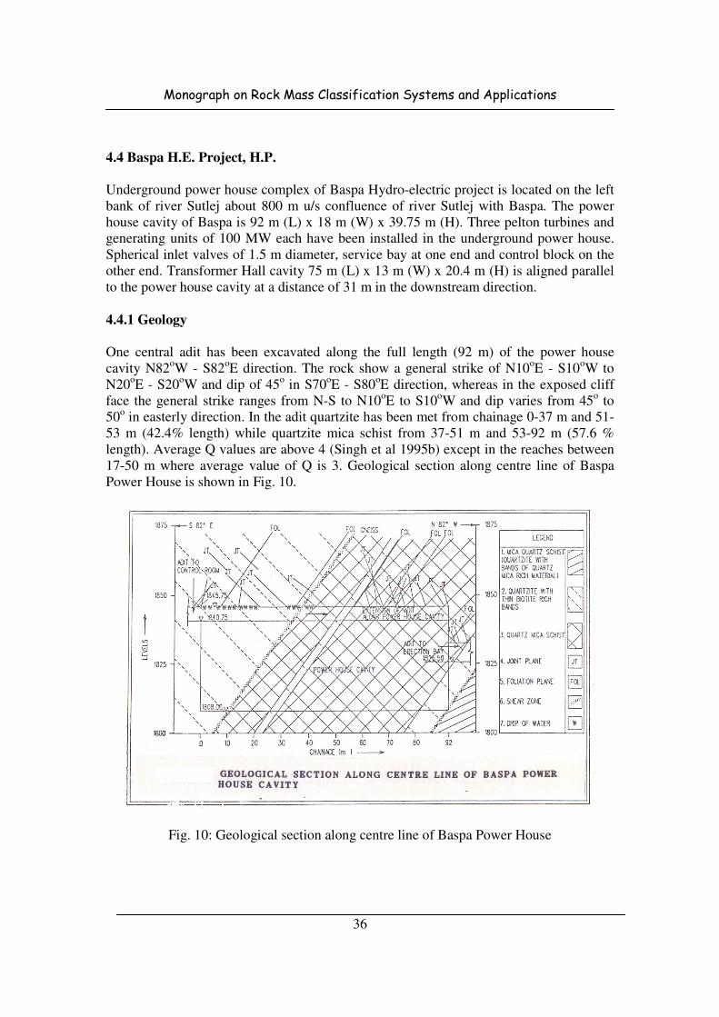
Monograph on Rock Mass Classification Systems and Applications
36
4.4 Baspa H.E. Project, H.P.
Underground power house complex of Baspa Hydro-electric project is located on the left
bank of river Sutlej about 800 m u/s confluence of river Sutlej with Baspa. The power
house cavity of Baspa is 92 m (L) x 18 m (W) x 39.75 m (H). Three pelton turbines and
generating units of 100 MW each have been installed in the underground power house.
Spherical inlet valves of 1.5 m diameter, service bay at one end and control block on the
other end. Transformer Hall cavity 75 m (L) x 13 m (W) x 20.4 m (H) is aligned parallel
to the power house cavity at a distance of 31 m in the downstream direction.
4.4.1 Geology
One central adit has been excavated along the full length (92 m) of the power house
cavity N82oW - S82
oE direction. The rock show a general strike of N10
oE - S10
oW to
N20oE - S20
oW and dip of 45
o in S70
oE - S80
oE direction, whereas in the exposed cliff
face the general strike ranges from N-S to N10oE to S10
oW and dip varies from 45
o to
50o in easterly direction. In the adit quartzite has been met from chainage 0-37 m and 51-
53 m (42.4% length) while quartzite mica schist from 37-51 m and 53-92 m (57.6 %
length). Average Q values are above 4 (Singh et al 1995b) except in the reaches between
17-50 m where average value of Q is 3. Geological section along centre line of Baspa
Power House is shown in Fig. 10.
Fig. 10: Geological section along centre line of Baspa Power House
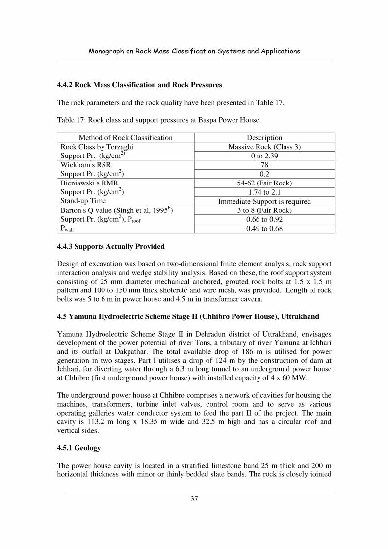
Monograph on Rock Mass Classification Systems and Applications
37
4.4.2 Rock Mass Classification and Rock Pressures
The rock parameters and the rock quality have been presented in Table 17.
Table 17: Rock class and support pressures at Baspa Power House
Method of Rock Classification Description
Rock Class by Terzaghi
Support Pr. (kg/cm2)
Massive Rock (Class 3)
0 to 2.39
Wickham’s RSR
Support Pr. (kg/cm2)
78
0.2
Bieniawski’s RMR
Support Pr. (kg/cm2)
Stand-up Time
54-62 (Fair Rock)
1.74 to 2.1
Immediate Support is required
Barton’s Q value (Singh et al, 1995
b)
Support Pr. (kg/cm2), Proof
Pwall
3 to 8 (Fair Rock)
0.66 to 0.92
0.49 to 0.68
4.4.3 Supports Actually Provided
Design of excavation was based on two-dimensional finite element analysis, rock support
interaction analysis and wedge stability analysis. Based on these, the roof support system
consisting of 25 mm diameter mechanical anchored, grouted rock bolts at 1.5 x 1.5 m
pattern and 100 to 150 mm thick shotcrete and wire mesh, was provided. Length of rock
bolts was 5 to 6 m in power house and 4.5 m in transformer cavern.
4.5 Yamuna Hydroelectric Scheme Stage II (Chhibro Power House), Uttrakhand
Yamuna Hydroelectric Scheme Stage II in Dehradun district of Uttrakhand, envisages
development of the power potential of river Tons, a tributary of river Yamuna at Ichhari
and its outfall at Dakpathar. The total available drop of 186 m is utilised for power
generation in two stages. Part I utilises a drop of 124 m by the construction of dam at
Ichhari, for diverting water through a 6.3 m long tunnel to an underground power house
at Chhibro (first underground power house) with installed capacity of 4 x 60 MW.
The underground power house at Chhibro comprises a network of cavities for housing the
machines, transformers, turbine inlet valves, control room and to serve as various
operating galleries water conductor system to feed the part II of the project. The main
cavity is 113.2 m long x 18.35 m wide and 32.5 m high and has a circular roof and
vertical sides.
4.5.1 Geology
The power house cavity is located in a stratified limestone band 25 m thick and 200 m
horizontal thickness with minor or thinly bedded slate bands. The rock is closely jointed
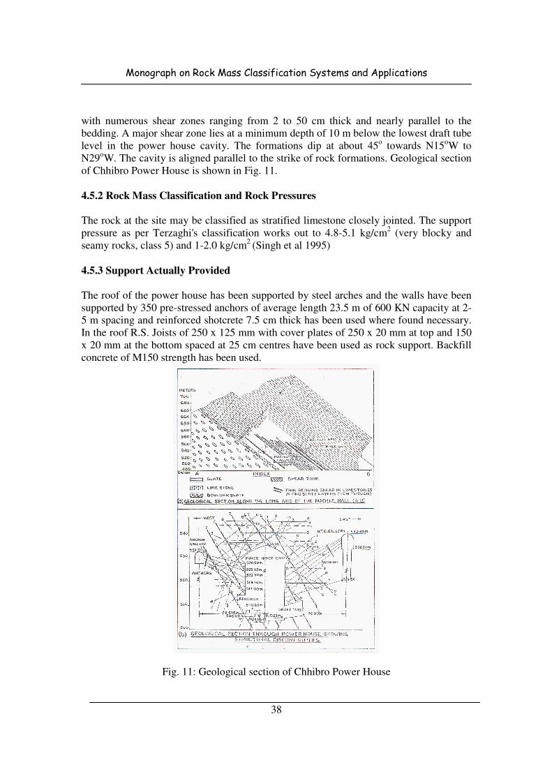
Monograph on Rock Mass Classification Systems and Applications
38
with numerous shear zones ranging from 2 to 50 cm thick and nearly parallel to the
bedding. A major shear zone lies at a minimum depth of 10 m below the lowest draft tube
level in the power house cavity. The formations dip at about 45o towards N15oW to
N29oW. The cavity is aligned parallel to the strike of rock formations. Geological section
of Chhibro Power House is shown in Fig. 11.
4.5.2 Rock Mass Classification and Rock Pressures
The rock at the site may be classified as stratified limestone closely jointed. The support
pressure as per Terzaghi's classification works out to 4.8-5.1 kg/cm2 (very blocky and
seamy rocks, class 5) and 1-2.0 kg/cm2
(Singh et al 1995)
4.5.3 Support Actually Provided
The roof of the power house has been supported by steel arches and the walls have been
supported by 350 pre-stressed anchors of average length 23.5 m of 600 KN capacity at 2-
5 m spacing and reinforced shotcrete 7.5 cm thick has been used where found necessary.
In the roof R.S. Joists of 250 x 125 mm with cover plates of 250 x 20 mm at top and 150
x 20 mm at the bottom spaced at 25 cm centres have been used as rock support. Backfill
concrete of M150 strength has been used.
Fig. 11: Geological section of Chhibro Power House

Monograph on Rock Mass Classification Systems and Applications
39
The side walls of the power house were reinforced by multiple strand pre-stressed,
sheathed cable anchors. Each anchor was made of 16 high tension steel wires (7 mm
diameter), provided with spacers at 1.5 m intervals. The anchor capacity was 450 to 600
kN. Anchors of 35 to 40 m length were installed in 75 mm diameter holes. The spacing
was 4.6 m in horizontal plane and 2.75 m in vertical plane. The steel bearing plates
provided were 150 x 150 x 35 mm at the loading nut end, and 750 x 750 x 16 mm at the
tensioning end, with additional 750 x 750 mm pads made of 75 mm thick shotcrete on
both sides of the anchor. These cable anchors were installed from draft tube operating
gallery (w 5 m) on the downstream side (25 m from power house) and from anchor drift
gallery (w 4 m) and adit to expansion chamber on the upstream side. This is a "single
wire" system where individual wires are stressed to 700 kN load , held for two minutes,
fully released and again stressed, and locked at 500 to 550 kN after 6 months. A total of
445 cables were installed in this way (231 on u/s side and 214 on d/s side). Over the
anchors, 75 mm thick shotcrete was applied, supplemented with chain link mesh and
perfo bolts. Roof and wall supports in Chhibro Power House are shown in Fig. 12.
Fig. 12: Roof and wall supports in Chhibro Power House

Monograph on Rock Mass Classification Systems and Applications
40
4.6 Lakhwar H.E. Project, Uttrakhand
Originally, Lakhwar project was planned to envisage the construction of 204 m high
concrete gravity dam across river Yamuna and an underground power house located
inside right abutment of the dam near village Lakhwar about 80 km from Dehradun in
Uttar Pradesh. The power house will have an installed capacity of 3 x 100 MW and shall
utilise a drop of 166 m. Power house cavity of 130 m (L) x 20 m (W) x 43.5 m (H) size
comes almost in line of dam axis. Layout of Lakhwar Power House is shown in Fig. 13.
4.6.1 Geology
At the power house location, the rock types were phylites, slates, shales, quartzites and
limestones of Jaunsar group with moderate to highly jointed basic intrusions of
dolerite/hornblende, and fine to coarse grained rhyolite/trap rock. Nine sets of joints have
been identified in the power house cavern formations. Some joints were slickensided, but
tight: some have mylonite or gouge infilling, or open with 10 mm aperture: dipping water
was present. The rock was traversed at places by quartz or calcite veins. A few shear
zones of 10 cm thickness were present.
4.6.2 Rock Mass Classification and Rock Pressures
The rock pressures and rock classes are presented in Table 18:
Table 18: Rock class and support pressures at Lakhwar Power House
Method of Rock Classification Description
Rock Class by Terzaghi
Support Pr. (kg/cm2) Massive to moderately jointed rock (Class 3)
0-2.65
Bieniawski’s RMR
Support Pr. (kg/cm2)
Stand-up Time
63 (Good Rock)
2.09
Immediate Support is required
Barton’s Q value (Singh et al, 1995
b)
Support Pr. (kg/cm2), Proof
8.5 (Fair Rock)
0.35
4.6.3 Supports Actually Provided
The power house cavity has been supported on ISMB 250 x 125 mm sets at 0.9 m
spacing (Fig. 14). Supplementary reinforcement was with 20 mm diameter, 3 to 5 m long,
mild steel rock bolts installed at 1.8 m spacing. The bolts were grouted in 40 mm
diameter holes using 1:1 sand-cement slurry, and tensioned (Singh et al 1988). In
addition, 70 mm thick shotcrete was applied in two layers over welded wire mesh (size
100 x 100 x 3 mm diameter wires). For the wedge blocks with safety factor less than 1.5,
additional rock bolting, shotcrete (using M-100 grade) and weld mesh were carried out.

Monograph on Rock Mass Classification Systems and Applications
41
Fig. 13: Layout of Lakhwar Power House
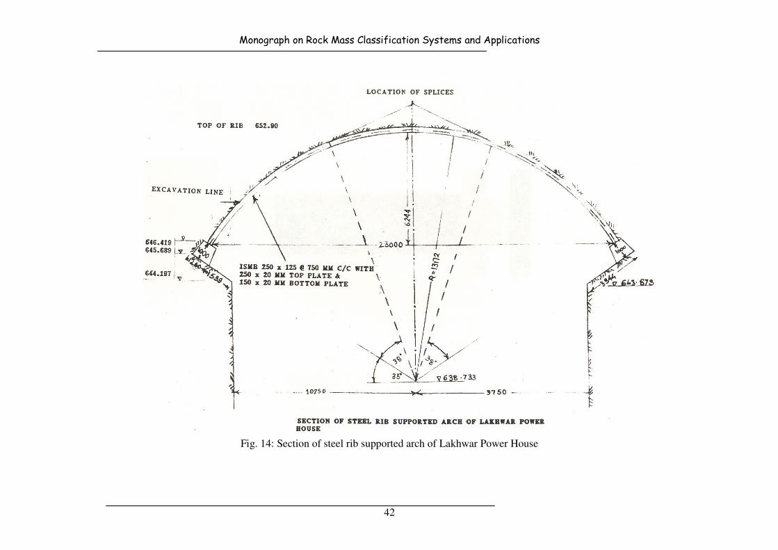
Monograph on Rock Mass Classification Systems and Applications
42
Fig. 14: Section of steel rib supported arch of Lakhwar Power House

Monograph on Rock Mass Classification Systems and Applications
43
For the side walls of the power house, 36 mm diameter, 8 to 9 m long grouted tensioned
bolts were used at 1.5 m spacing, plus 10 cm thick shotcrete over 100 x 100 x 4.2 mm
welded wire mesh. The east face wall was reinforced with 25 mm diameter, 8 m long
expansion shell bolts, post grouted and tightened to 100 kN tension. The bolts were fixed
at an inclination of 15o downwards from horizontal, using bevel washers.
4.7 Chamera H.E. Project, H.P.
Chamera Power Station Stage-I (540 MW) is a run-of-the-river scheme built on river
Ravi, which is a major river of the Indus Basin, originating in the Himalayas from the
Baira Bhanghal branch of the Dhaula Dhar Range. The project utilises the Hydro Power
potential available after the confluence of the river Siul with Ravi. The project was
commissioned in April 1994. The project comprise of a 140 m high, 295 m long concrete
arch gravity dam, a 6.4 km long & 9.5 m dia head race tunnel and Underground Power
House containing 3 units of 180 MW each.
4.7.1 Geology
The powerhouse complex comprising of two caverns viz. the machine hall and
transformer hall and other ancillary components have been excavated in granite gneiss,
carbonaceous phylite, graphitic phylite, limestone, metavolcanics, sandstone, and shale.
The rock formations were intensely folded, with three major thrust zones present. The
power house was located under a cover of 230 m in fine grained metamorphosed andesite
basalt (metavolcanics), blocky to foliated and intersected by five sets of discontinuities of
different orientations. The rock mass was generally 'fair', but poor in foliated crushed
zone. Foliation joints were continuous and undulating and generally moderate to closely
spaced. Most of the joint sets have low persistence. Water seepage in caverns during
excavation was negligible. Geological section of Chamera Project is shown in Fig. 15.
4.7.2 Rock Mass Classification and Rock Pressures
The rock mass classification and support pressures are given in Table 19.
Table 19: Rock class and support pressures at Chamera Power House
Method of classification Description
Rock Class by Terzaghi
Support Pr. (kg/cm2)
Blocky to foliated Rock Mass (Class 4)
1.65-5.87
Bieniawski’s RMR
Support Pr. (kg/cm2)
50 (Fair Rock)
3.3
Barton’s Q value (Sharma et al 1994)
Support Pr. (kg/cm2), Proof
Pwall
1.95
1.07
0.62

Monograph on Rock Mass Classification Systems and Applications
44
Fig. 15: Geological section of Chamera Project
4.7.3 Support Actually Provided
Flexible support system consisting of combination of rock bolts, anchors and shotcrete
with wire mesh was considered prudent with regular monitoring of excavated section by
instrumentation. Depth of anchors was sufficient to ensure formation of the required zone
of compression. Rock reinforcement in Chamera Power House is shown in Fig. 16.
Fig. 16: Rock reinforcement in Chamera Power House
Rock Bolts 6 m long, 2 x 2 m spacing
Monograph on Rock Mass Classification Systems and Applications
45
Based on this design approach, the following support systems were adopted.
• 7.5 m long and 25 mm diameter rock bolts (yield strength 267 KN) on 1.5 m
square grid.
• 6.0 m long and 25 mm diameter rock bolts (yield strength 204 KN), on a 1.5 m
square grid as primary support and longer , 51 mm diameter hollow core anchors,
10.5 m long of 843 KN on a 4.5 m square grid as the secondary support.
4.8 Kadamparai Pumped Storage H.E. Project, Tamilnadu
The project constructed by Tamilnadu Electricity Board in South India has been designed
to meet the peaking requirements of Tamilnadu grid. The project envisages construction
of a dam across the Kadamparai River for forming the upper reservoir and utilisation of
the existing Upper Aliyar Reservoir as a tail pool. The project has an underground
powerhouse of 128.5 m (L) x 20.9 m (W) x 38.0 m (H) size of 400 MW installed
capacity.
4.8.1 Geology
The area encomapssing the Kadamparai scheme is occupied by biotite gneiss intruded by
pegmatites. The gneisses are folded but the folds are generally tight along the water
conductor system. From the Kadamparai dam to the tail race tunnel outlet, granite gneiss
with veins of pegmatite are met with. General foliation of the gneisses varies from NNE -
SSW direction, with dips ranging from 60o to 80
o in the easterly direction. There are three
sets of joints in gneisses.
Set No. Strike of Joint Set Dip
Set 1 N25oW - S25oE 10o-20o in S65o
Set 2 N75oE - S75oW Vertical
Set 3 NE - SW 70o towards SE
4.8.2 Rock Mass Classification and Rock Pressures
Rocks have been classified by Terzaghi's method as moderately jointed (Class 3) with
rock pressure varying from 0-2.84 kg/cm2. By Singh et al 1995, the support pressures
should be 0.7-1.0 kg/cm2.
4.8.3 Support Actually Provided
The arch portion of the roof has been reinforced with 20 mm diameter, 5 to 7 m long
expansion shell mechanically anchored grouted bolts at a spacing of 2 x 2 m,
subsequently grouted to full length using thick cement grout. Additionally 7.5 cm thick
guniting has been carried out over chain link fabric. In view of the occurrence of minor
cracks both in the upstream and downstream walls, the side walls were also reinforced
with similar bolts of 5 - 7 m length supplemented with 7.5 cm thick guniting and chain
link mesh. Rock reinforcement in Kadamparai Power House is shown in Fig. 17.

Monograph on Rock Mass Classification Systems and Applications
46
Fig. 17: Rock reinforcement in Kadamparai Power House
4.9 Chukha H.E Project, Bhutan
Chukha hydroelectric project was constructed during 1973 to 1986 across river Wangchu
making use of 468 m head near Chimakothi in Bhutan. It is a run of the river project. The
336 MW power house (4 x 84 MW) located under 230 m rock cover and 40 m laterally
inside the hill, was excavated in granitic rocks.
4.9.1 Geology
The rock mass encountered around the underground power house was granite gneiss and
migmatite with intervening bands and lenses of mica schist, quartzite and amphibolites of
Thimpu series. With and RMR of 70, this rock was expected to be competent and self
supporting for a 25 m span. However, because of the highly jointed and fractured nature
and the occurrence of minor schist bands, the excavations did not stand beyond 6 m.
4.9.2 Rock Classifications and Support Pressures
RMR value of granite gneiss rock mass has been calculated as 70 which correspond to
good class. For this RMR, the support pressure works out to be 0.3 kg/cm2.
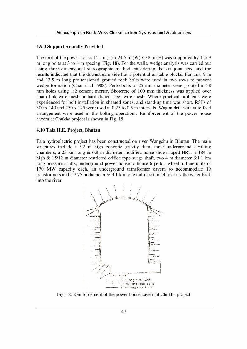
Monograph on Rock Mass Classification Systems and Applications
47
4.9.3 Support Actually Provided
The roof of the power house 141 m (L) x 24.5 m (W) x 38 m (H) was supported by 4 to 9
m long bolts at 3 to 4 m spacing (Fig. 18). For the walls, wedge analysis was carried out
using three dimensional stereographic method considering the six joint sets, and the
results indicated that the downstream side has a potential unstable blocks. For this, 9 m
and 13.5 m long pre-tensioned grouted rock bolts were used in two rows to prevent
wedge formation (Char et al 1988). Perfo bolts of 25 mm diameter were grouted in 38
mm holes using 1:2 cement mortar. Shotcrete of 100 mm thickness was applied over
chain link wire mesh or hard drawn steel wire mesh. Where practical problems were
experienced for bolt installation in sheared zones, and stand-up time was short, RSJ's of
300 x 140 and 250 x 125 were used at 0.25 to 0.5 m intervals. Wagon drill with auto feed
arrangement were used in the bolting operations. Reinforcement of the power house
cavern at Chukha project is shown in Fig. 18.
4.10 Tala H.E. Project, Bhutan
Tala hydroelectric project has been constructed on river Wangchu in Bhutan. The main
structures include a 92 m high concrete gravity dam, three underground desilting
chambers, a 23 km long & 6.8 m diameter modified horse shoe shaped HRT, a 184 m
high & 15/12 m diameter restricted orifice type surge shaft, two 4 m diameter &1.1 km
long pressure shafts, underground power house to house 6 pelton wheel turbine units of
170 MW capacity each, an underground transformer cavern to accommodate 19
transformers and a 7.75 m diameter & 3.1 km long tail race tunnel to carry the water back
into the river.
Fig. 18: Reinforcement of the power house cavern at Chukha project
Monograph on Rock Mass Classification Systems and Applications
48
4.10.1 Power House
The underground power house of 206 m x 44.5 m x 20.4 m size was constructed to house
6 pelton wheel turbine units of 170 MW capacity each and a total installed capacity of
1020 MW. The transformer cavern of 191 m x 26.5 m x 16 m size was constructed
parallel to power house cavern to accommodate 19 transformers.
4.10.1.1 Geology
The geological mapping has indicated that the ridge which houses the machine hall and
the transformer hall cavern, is occupied by fresh and hard, inter banded sequence of
quartzite, phyllitic quartzite, phyllitic with quartzite boudins and amphibolite schist
partings. These rocks are highly puckered and folded into synform and antiform. The
general foliation trend varies from N65oE-S65
oW to N70
oW-S70
oE with 35
o to 60
o
N25oW to N20
oE dips. The plunge of the folds recorded at RD 16m (25
o/270
o), RD 93 m
(18o/56
o), RD 128m (10
o/90
o), RD 143 m (15
o/130
o) and at RD 183m (10
o/88
o). The
joints recorded in the central gullet excavation are given in Table 20.
The long axis of the powerhouse in N37oW-S37oE direction is across the strike of
foliation. Due to folding, the angle between the long axis of powerhouse and the strike of
formation varies from 15o to 55o.
Table 20: Major Discontinuities in Machine Hall Cavern
Sl. No. Strike
Dip Spacing
cm
Continuity
cm
Nature
Foliation N65oE-S65
oW
to N70oW-S70
oE
35o-60
o:
N25oW to N20
oE
10-300 500-1200 Rough
Undulating
J1
N20oW-S70
oE
to N15oW-S75
oE
40o-80
o:
N7oE to N75
oE
100-200 200-500 Rough
Undulating
J2 N-S
to N30oE-S30
oW
25-80:
W to N60oW
5-200 200-1000 Rough
Undulating
J3 N30oE-S30oW
to N20o E-S20
oW
30-50o:
S60oE to S70
oE
6-20 200 Rough
Planner
J4 N50oW-S50E
o
To N30oW-S60
oE
60o-70
o:
S40oW-S60
oW
10-200 200-500 Smooth
Planner
J5 N80oE-S80W
o
to N70oW-S20
oE
40o-70
o:
S10oE to S20
oW
20-200 200-500 Rough
Planner
The rock mass in the first bench has been mostly in class IV with Q values (Grimstad and
Barton 1993) varying from 2.5 to 4 mainly due to bottom effect while rock mass
conditions in the second bench had shown improvement and has been classified mostly in
class III with Q values varying from 4.2 to 10.5. Excavation for third bench (trench) in
progress had shown considerable improvement in rock mass conditions and is in class III.
Collapse of the drill holes in first bench between RD 120-125 m has been observed due to
the presence of quartz veins in the holes.
Monograph on Rock Mass Classification Systems and Applications
49
4.10.1.2 Rock Mass Classification and Rock Pressures
During pre-construction stage, the detailed mapping of the drift parallel to the alignment
of machine hall crown matching with its crown revealed maximum stretch falling in fair
category of rock mass though the Q values varied from 0.24 (very poor) to 13.2 (very
good). The geological strength index was computed as 50.
4.10.1.3 Support Actually Provided
Excavation of powerhouse cavern was taken up in conventional drill and blast method
starting with excavation of 7 m wide and 7.5m height central gullet with its invert level at
El 531 m, suiting to the final profile of the cavern. The gullet was supported with 32 mm
dia and 6 m long rock bolts with expansion shell end anchorage at 3 m by 1.5m pattern.
SFRS of 100mm thickness was applied after installation of rock bolts. After the roof
support of central gullet, its widening was taken up first on downstream side followed by
upstream side by keeping a distance of about 20 m between faces of semi-widened
sections. Concurrent supporting in the widened portion was completed with 6 m and 8 m
(6 m + 2 m) long and 32 mm dia rock bolts (alternative) both ways staggered @ 1500
mm c/c along with SFRS of 75 mm-100 mm thick. Sequence and period of excavation in
power house cavern are shown in Fig.19.
Many problems were encountered during crown excavation and finally it was supported
with conventional support system of steel ribs of ISMB 350x140 with 12 mm thick plates
on both the flanges @ 0.6 m c/c in conjunction with 32 mm dia and 8 m/10 m long rock
bolts @ 3 m c/c staggered after collapse of portion of the crown. Having faced collapse
during crown widening, methodology of excavation and support system for benching
operation was reviewed through investigations by a borehole camera, testing for physical
properties of the rock mass and on review 3-D numerical analysis so as to have proper
and smooth benching down of the cavern. Support system review comprises 3 shotcrete
layers of 50mm each and 12m long and 26.5 mm/32 mm diameter Dywidag rock bolts
(with tensile strength equal to 57 tons) @ 1.5 m c/c with 100 mm x 100 mm x 5 mm wire
mesh.
The systematic rock mass excavation with controlled blasting and concurrent support
system during benching down in powerhouse cavern was adopted. Bench depths have
been fixed between 2.5 m to 3.5 m depending upon rock mass conditions. In the first
bench, the rock mass has been excavated by providing central gullet of 6 m width.
Adopting safe blast design in staggered manner, sides through nitches of 3 m sizes were
excavated. As the rock parameters improved with every bench, width of central gullet
was increased to 8 m and opening of sides was done with 6 m long nitches in the second
bench. The lengths of nitches were increased subsequently to 9 m in third bench onwards
to enhance the pace of excavation. During the bench excavation wall support system was
ensured within 48 hours after the excavation except for 5% of the events such as in initial
nitches.

Monograph on Rock Mass Classification Systems and Applications
50
EL 538.5
EL 531
EL 528.5
EL 525
EL 521.5
EL 518.5
EL 515.5
EL 513
7m
11-Dec-00 to 23-Mar-01
102 Days
D/s U/s
I II III
05-Apr-01 to 25-Dec-01
264 Days
07-Apr-01 to 15-Dec-01
252 Days
IV
6.5m 7.1m 7.1m
28-May-02 to 17-Oct-02
142 Days
11-May-02 to 30-May-02
19 Days 23-May-02 to 08-Oct-02
138 Days
10m 5.2m 5.2m
19-Aug-02 to 27-Nov-02
100 Days
V
19-Oct-02 to 06-Dec-02
81 Days
12-Sep-02 to 27-Oct-02
45 Days
6.35m 6.35m 8m
07-Oct-02 to 10-Nov-02
34 Days 21-Oct-02 to 18-Nov-02
28 Days
09-Sep-02 to 29-Nov-02
VI
VII
VIII
IX
X
XI
XII
XIII
First Bench
Second Bench
Third Bench
Fourth Bench
Fifth Bench
Sixth Bench
Seventh Bench
Eighth Bench
Ninth Bench
Tenth Bench
11-Dec-02 to 29-Dec-02
18 Days
48 Days
14-Nov-02 to 04-Dec-02
20 Days
07-Nov-02 to 26-Dec-02
49 Days
20-Dec-02 to 17-Jan-03
28 Days
02-Jan-03 to 09-Feb-03
38 Days
31-Dec-02 to 17-Jan-03
17 Days
6.85m 7.0m 6.85m
25-Jan-03 to 24-Feb-03
30 Days
19-Jan-03 to 11-Jan-03
23 Days
26-Jan-03 to 26-Feb-03
31 Days
07-Mar-03 to 23-Mar-
16 Days
23-Feb-03 to 1-Mar-03
6 Days
26-Feb-03 to 28-Mar-03
30 Days
EL 510
EL 507
23-Mar-03 to 31-Mar-
8 Days
16-Mar-03 to 23-Mar-03
7 Days
21-Mar-03 to 29-Mar-
8 Days
EL 504
EL 501
(11-May-02 to 17-Oct-02) 159 days
(19-Aug-02 to 29-Nov-02) 102 days
(07-Oct-02 to 06-Dec-02) 60 days
(07-Nov-02 to 29-Dec-02) 52 days
(20-Dec-02 to 09-Feb-03) 51 days
(19-Jan-03 to 26-Feb-03) 38 days
(23-Feb-03 to 28-Mar-03) 33 days
(16-Mar-03 to 31-Mar-03) 15 days
Under Extraction
Under Extraction
Based on investigations by borehole camera, physical properties of the rock mass, and 3-
D numerical analysis for upstream and downstream walls of the cavern, the support
system comprising 12 m long Dywidag rockbolts @ 1.5 m c/c staggered both ways with
wire mesh and 150mm thick shotcrete on the walls has been contemplated for the walls.
Fig. 19: Date wise sequence of excavation of Machine hall.
4.10.2 Head Race Tunnel
The water conductor system of Tala hydroelectric project in Bhutan consist of 6.8 m
diameter modified horse shoe shaped HRT terminating into a 184 m high surge shaft and
then two pressure shafts of 4 m diameter and 1.1 km long each. The entire HRT was
divided into four packages.
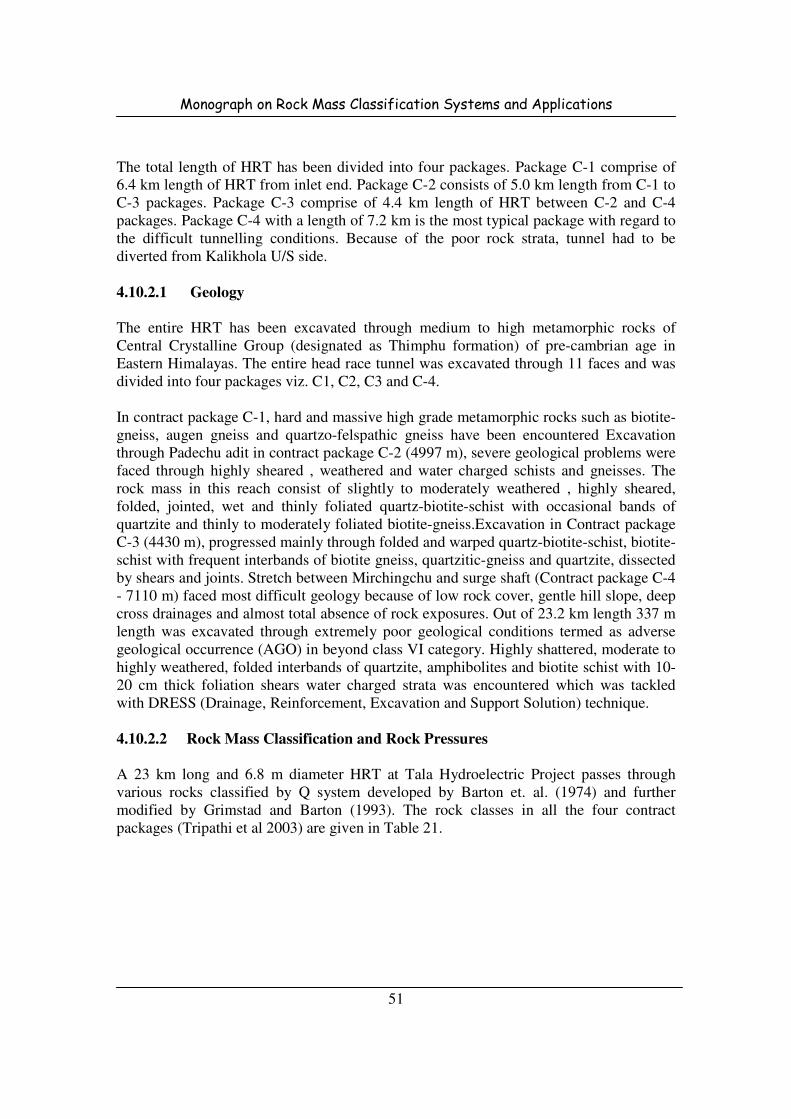
Monograph on Rock Mass Classification Systems and Applications
51
The total length of HRT has been divided into four packages. Package C-1 comprise of
6.4 km length of HRT from inlet end. Package C-2 consists of 5.0 km length from C-1 to
C-3 packages. Package C-3 comprise of 4.4 km length of HRT between C-2 and C-4
packages. Package C-4 with a length of 7.2 km is the most typical package with regard to
the difficult tunnelling conditions. Because of the poor rock strata, tunnel had to be
diverted from Kalikhola U/S side.
4.10.2.1 Geology
The entire HRT has been excavated through medium to high metamorphic rocks of
Central Crystalline Group (designated as Thimphu formation) of pre-cambrian age in
Eastern Himalayas. The entire head race tunnel was excavated through 11 faces and was
divided into four packages viz. C1, C2, C3 and C-4.
In contract package C-1, hard and massive high grade metamorphic rocks such as biotite-
gneiss, augen gneiss and quartzo-felspathic gneiss have been encountered Excavation
through Padechu adit in contract package C-2 (4997 m), severe geological problems were
faced through highly sheared , weathered and water charged schists and gneisses. The
rock mass in this reach consist of slightly to moderately weathered , highly sheared,
folded, jointed, wet and thinly foliated quartz-biotite-schist with occasional bands of
quartzite and thinly to moderately foliated biotite-gneiss.Excavation in Contract package
C-3 (4430 m), progressed mainly through folded and warped quartz-biotite-schist, biotite-
schist with frequent interbands of biotite gneiss, quartzitic-gneiss and quartzite, dissected
by shears and joints. Stretch between Mirchingchu and surge shaft (Contract package C-4
- 7110 m) faced most difficult geology because of low rock cover, gentle hill slope, deep
cross drainages and almost total absence of rock exposures. Out of 23.2 km length 337 m
length was excavated through extremely poor geological conditions termed as adverse
geological occurrence (AGO) in beyond class VI category. Highly shattered, moderate to
highly weathered, folded interbands of quartzite, amphibolites and biotite schist with 10-
20 cm thick foliation shears water charged strata was encountered which was tackled
with DRESS (Drainage, Reinforcement, Excavation and Support Solution) technique.
4.10.2.2 Rock Mass Classification and Rock Pressures
A 23 km long and 6.8 m diameter HRT at Tala Hydroelectric Project passes through
various rocks classified by Q system developed by Barton et. al. (1974) and further
modified by Grimstad and Barton (1993). The rock classes in all the four contract
packages (Tripathi et al 2003) are given in Table 21.
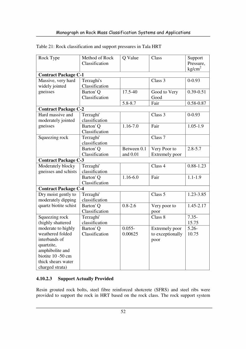
Monograph on Rock Mass Classification Systems and Applications
52
Table 21: Rock classification and support pressures in Tala HRT
Rock Type Method of Rock
Classification
Q Value Class Support
Pressure,
kg/cm2
Contract Package C-1
Massive, very hard
widely jointed
gneisses
Terzaghi's
Classification
Class 3 0-0.93
Barton' Q
Classification
17.5-40 Good to Very
Good
0.39-0.51
5.8-8.7 Fair 0.58-0.87
Contract Package C-2
Hard massive and
moderately jointed
gneisses
Terzaghi'
classification
Class 3 0-0.93
Barton' Q
Classification
1.16-7.0 Fair 1.05-1.9
Squeezing rock Terzaghi'
classification
Class 7
Barton' Q
Classification
Between 0.1
and 0.01
Very Poor to
Extremely poor
2.8-5.7
Contract Package C-3
Moderately blocky
gneisses and schists
Terzaghi'
classification
Class 4 0.88-1.23
Barton' Q
Classification
1.16-6.0 Fair 1.1-1.9
Contract Package C-4
Dry moist gently to
moderately dipping
quartz biotite schist
Terzaghi'
classification
Class 5 1.23-3.85
Barton' Q
Classification
0.8-2.6 Very poor to
poor
1.45-2.17
Squeezing rock
(highly shattered
moderate to highly
weathered folded
interbands of
quartzite,
amphibolite and
biotite 10 -50 cm
thick shears water
charged strata)
Terzaghi'
classification
Class 8 7.35-
15.75
Barton' Q
Classification
0.055-
0.00625
Extremely poor
to exceptionally
poor
5.26-
10.75
4.10.2.3 Support Actually Provided
Resin grouted rock bolts, steel fibre reinforced shotcrete (SFRS) and steel ribs were
provided to support the rock in HRT based on the rock class. The rock support system

Monograph on Rock Mass Classification Systems and Applications
53
adopted to support the HRT at Tala hydroelectric project in Bhutan is presented in Table
22.
Table 22: Rock classification and support system for Tala HRT
Rock mass class Designed support Alternate support
Class-I (Very good
rock mass with
Q>40)
Spot bolting (25 φ, 3500 mm long) or
local application of 50 mm SFRS (as
required)
-
Class-II (Good rock
mass with Q=10-40)
Rock bolt (25 φ, 3500 mm long) @ 1750
mm c/c both ways staggered or 50 mm
SFRS from haunch to haunch plus spot
bolting (25 φ, 3500 mm long)
-
Class-III (Fair rock
mass with Q=4-10)
Pattern bolting (25 φ, 3500 mm long),
1750 c/c both ways staggered along with
50 mm SFRS upto spring level.
-
Class-IV (Poor rock
mass with Q=1-4)
Pattern bolting (25 φ, 4000 mm long),
1500 c/c both ways staggered along with
100 mm SFRS upto invert level.
Steel ribs ISMB-250 @
750 mm c/c, 50 mm
SFRS and backfill
concrete
Class-V (Very poor
rock mass with
Q=0.1-1)
Pattern bolting (25 φ, 4000 mm long),
1250 c/c both ways staggered along with
150 mm SFRS upto invert level.
Steel ribs ISMB-250 @
600 mm c/c, 75 mm
SFRS and backfill
concrete
Class-VI (Extremely
poor rock mass with
Q=0.01-0.1
- Steel ribs ISMB-250 @
500 mm c/c, 100 mm
SFRS and backfill
concrete
Steel ribs of ISMB 250 x 125 @ 0.5 m spacing with bottom struts were installed for
supporting the excavated tunnel in the highly squeezing and extremely poor geological
section termed as adverse geological occurrence (AGO) zone. However, upheaval of the
invert also took place in course of time in this squeezing zone. Because of this upheaval,
bending/cracking of bottom struts also took place (Fig. 20). These struts were replaced
before start of reinforced concrete lining in this zone to avoid any additional loads on
R.C.C. Lining.
4.11 Ramganga Project Tunnels, U.P.
Ramganga dam, 126 m high earth and boulder fill dam has been constructed across river
Ramganga, a tributary of river Ganga. Based upon economical studies and feasibility of
construction of the 1st stage dam for diversion of floods, two tunnels of 9.45 m internal
diameter are constructed in the right abutment of the dam. In order to make maximum
utilisation of the tunnels as permanent works after construction of dam, is over, eastern
tunnel (No. 1) was converted to power tunnel and western tunnel (No. 2) was utilised as
outlet works for releasing water for irrigation requirements when power house is closed
or for emergency dewatering of the reservoir in case of damage to the power house.
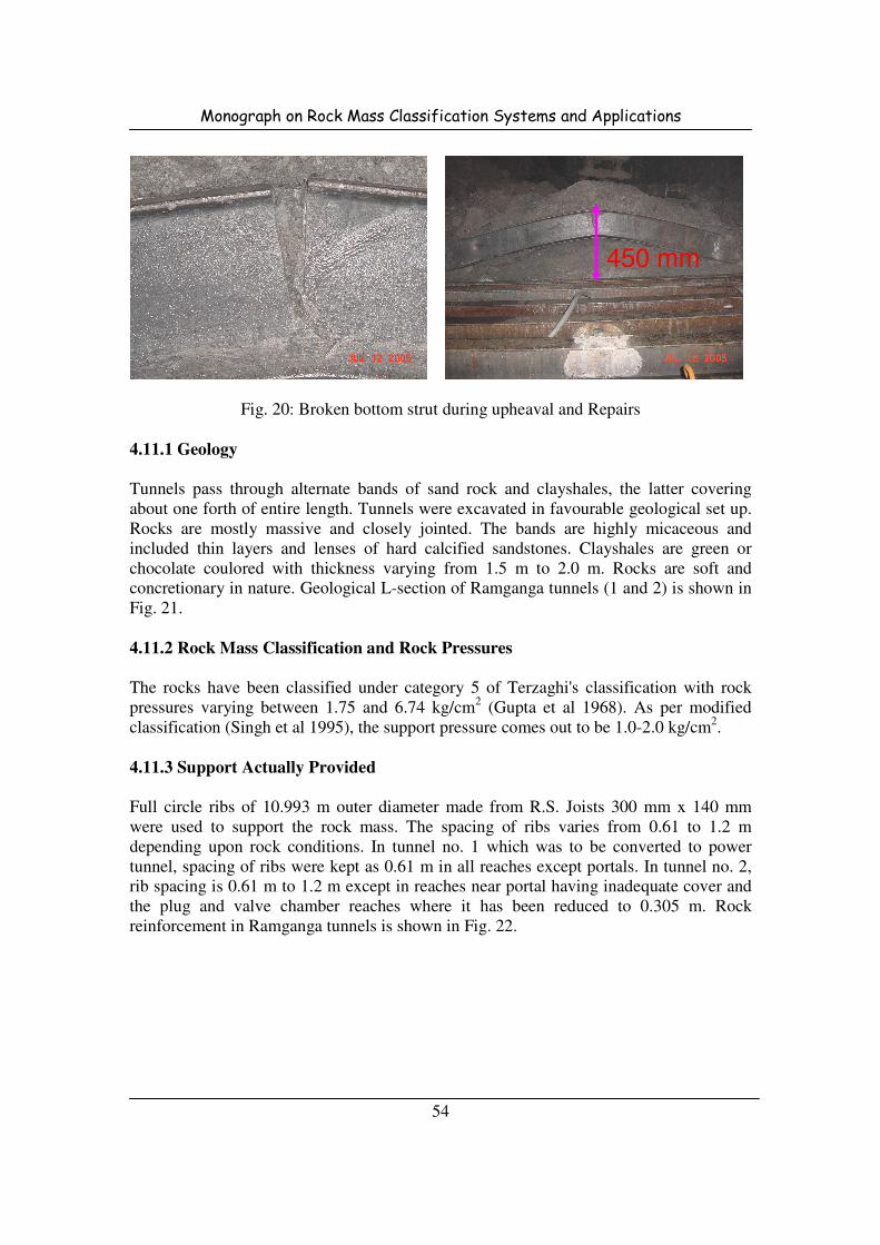
Monograph on Rock Mass Classification Systems and Applications
54
Fig. 20: Broken bottom strut during upheaval and Repairs
4.11.1 Geology
Tunnels pass through alternate bands of sand rock and clayshales, the latter covering
about one forth of entire length. Tunnels were excavated in favourable geological set up.
Rocks are mostly massive and closely jointed. The bands are highly micaceous and
included thin layers and lenses of hard calcified sandstones. Clayshales are green or
chocolate coulored with thickness varying from 1.5 m to 2.0 m. Rocks are soft and
concretionary in nature. Geological L-section of Ramganga tunnels (1 and 2) is shown in
Fig. 21.
4.11.2 Rock Mass Classification and Rock Pressures
The rocks have been classified under category 5 of Terzaghi's classification with rock
pressures varying between 1.75 and 6.74 kg/cm2 (Gupta et al 1968). As per modified
classification (Singh et al 1995), the support pressure comes out to be 1.0-2.0 kg/cm2.
4.11.3 Support Actually Provided
Full circle ribs of 10.993 m outer diameter made from R.S. Joists 300 mm x 140 mm
were used to support the rock mass. The spacing of ribs varies from 0.61 to 1.2 m
depending upon rock conditions. In tunnel no. 1 which was to be converted to power
tunnel, spacing of ribs were kept as 0.61 m in all reaches except portals. In tunnel no. 2,
rib spacing is 0.61 m to 1.2 m except in reaches near portal having inadequate cover and
the plug and valve chamber reaches where it has been reduced to 0.305 m. Rock
reinforcement in Ramganga tunnels is shown in Fig. 22.
450 mm
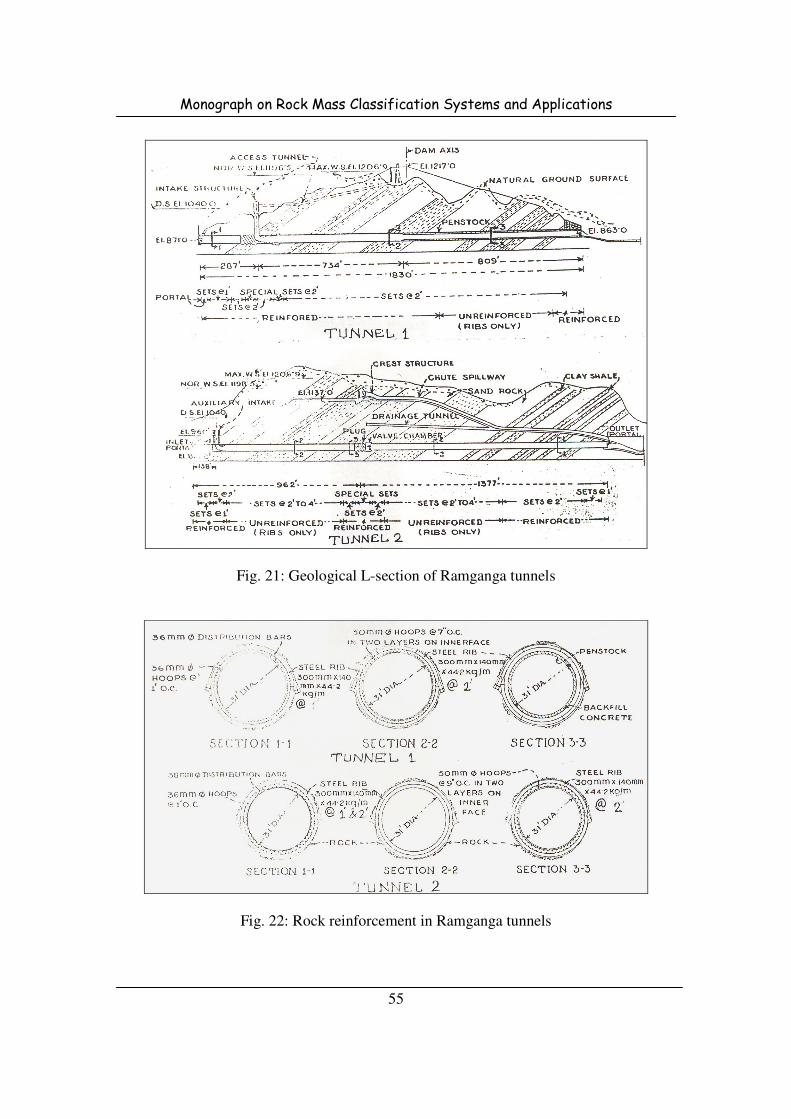
Monograph on Rock Mass Classification Systems and Applications
55
Fig. 21: Geological L-section of Ramganga tunnels
Fig. 22: Rock reinforcement in Ramganga tunnels

Monograph on Rock Mass Classification Systems and Applications
56
4.12 Narmada Sagar Project, M.P.
Narmada Sagar Project near Punasa comprise of 92 m high concrete gravity dam across
river Narmada to divert 2040 cusec of water through 40 to 55 m deep, 450 m long head
race tunnel to feed pressure shafts of 8 m finished diameter to generate 1000 MW (8 x
125 MW) of power in a 55 m deep pit power house and release the tail water back into
the Narmada river through 25-48 m deep 865 m long tail channel.
4.12.1 Geology
The tunnelling media is quartz arenites (quartzites) and ferruginous fine grained
sandstones with the intercalated layers of silt/clay stones. The pressure shafts are aligned
parallel to the general trend of the rocks in N50oE to S50
oW direction. The beds dip by
20o to 35
o towards NNW i.e. towards right abutment with occasional dips of 40o due to
local warping between pressure shafts No. 5 and 8. L-section of pressure tunnels of
Narmada Sagar Project is shown in Fig. 23.
The rock mass has been characterised in three categories as follows:
Category 1 - Quartz Arenites (Quartzites)
Category 2 - Ferruginous Sand Stones
Category 3 - Ferruginous Silt/Clay Stones
Fig. 23: L-section of pressure tunnels of Narmada Sagar Project
4.12.2 Rock Mass Classification and Rock Pressures
The rock mass has been classified as per the available methods and the support pressures
are as per Table 23.
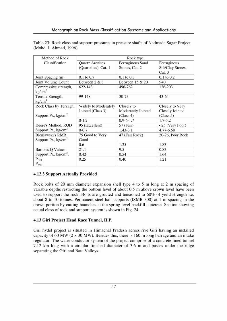
Monograph on Rock Mass Classification Systems and Applications
57
Table 23: Rock class and support pressures in pressure shafts of Nadmada Sagar Project
(Mohd. J. Ahmad, 1996)
Method of Rock
Classification
Rock type
Quartz Arenites
(Quartzites), Cat. 1
Ferruginous Sand
Stones, Cat. 2
Ferruginous
Silt/Clay Stones,
Cat. 3
Joint Spacing (m) 0.1 to 0.7 0.1 to 0.3 0.1 to 0.2
Joint Volume Count Between 2 & 8 Between 15 & 20 >40
Compressive strength,
kg/cm2
622-143 496-762 126-203
Tensile Strength,
kg/cm2
99-148 30-73 43-64
Rock Class by Terzaghi
Support Pr., kg/cm2
Widely to Moderately
Jointed (Class 3)
Closely to
Moderately Jointed
(Class 4)
Closely to Very
Closely Jointed
(Class 5)
0-1.2 0.9-6-1.7 1.7-5.2
Deere's Method, RQD
Support Pr., kg/cm2
95 (Excellent) 57 (Fair) <25 (Very Poor)
0-0.7 1.43-3.1 4.77-6.68
Bieniawski's RMR
Support Pr., kg/cm2
75 Good to Very
Good
47 (Fair Rock) 20-26, Poor Rock
0.6 1.25 1.83
Barton's Q Values
Support Pr., kg/cm2,
Proof
Pwall
21.1 9.5 0.83
0.42 0.54 1.64
0.25 0.40 1.21
4.12.3 Support Actually Provided
Rock bolts of 20 mm diameter expansion shell type 4 to 5 m long at 2 m spacing of
variable depths restricting the bottom level of about 0.5 m above crown level have been
used to support the rock. Bolts are grouted and tensioned to 60% of yield strength i.e.
about 8 to 10 tonnes. Permanent steel half supports (ISMB 300) at 1 m spacing in the
crown portion by cutting haunches at the spring level backfill concrete. Section showing
actual class of rock and support system is shown in Fig. 24.
4.13 Giri Project Head Race Tunnel, H.P.
Giri hydel project is situated in Himachal Pradesh across rive Giri having an installed
capacity of 60 MW (2 x 30 MW). Besides this, there is 160 m long barrage and an intake
regulator. The water conductor system of the project comprise of a concrete lined tunnel
7.12 km long with a circular finished diameter of 3.6 m and passes under the ridge
separating the Giri and Bata Valleys.

Monograph on Rock Mass Classification Systems and Applications
58
Fig. 24: Section showing actual class of rock and support system
4.13.1 Geology
The tunnel passes through various types of rocks namely slate/phyllites interbedded with
quartzites, shales of various shades, limestone conglomerates and sandstones of various
grades. The most important feature from the engineering geology view point was the
occurrence of three thrusts lying in the close proximity to one another. Tunnel crosses
two major regional thrusts (Viz. Krol and Nahan) which were considered most
problematic zones for tunnelling operations.
Along the tunnel alignment, the strata changes to claystones and siltstones which are
highly jointed and deteriorate on saturation with water. The material in vicinity of faults
is highly saturated, soft and plastic. However, near the outlet of the tunnel, the strata
generally comprise of sandstones and siltstones. Geological L-section of Giri Project
HRT is shown in Fig. 25.
Fig. 25: Geological L-section of Giri Project HRT

Monograph on Rock Mass Classification Systems and Applications
59
4.13.2 Rock Mass Classification and Rock Pressures
The rock mass has been classified as per the available methods and the support pressures
are as per Table 24.
Table 24: Rock class and support pressures in Giri HRT
Method of Rock Classification Rock type
Slates Phyllites
Rock Class by Terzaghi
Support Pr., kg/cm2
Very Blocky and Seamy
(Mild Squeezing), Class 7
Crushed Phyllites (Highly
Squeezing), Class 8
2.4-4.6 6.1-11.6
Deere's Method, RQD
Support Pr., kg/cm2
5-25 5-25
1.88-3.12 60.75 (Upto 75 m rock)
Bieniawski's RMR
Support Pr., kg/cm2
38, Very Poor 25, Very Poor
0.7 0.84
Barton's Q Values (Jethwa et al 1982)
Support Pr., kg/cm2
0.51 0.12
2.4 3.4
4.13.3 Support Actually Provided
Horse shoe shaped steel sets with bottom struts were used to support the rock. Two steel
sections viz. 150 x 80 mm and 150 x 150 mm have been used with varying spacing given
in Table 25.
Table 25: Rib support systems in Giri HRT
Rib Section Spacing Capacity in Tonnes (Fibre Stress = 2500 kg/cm2)
150 x 80 1.0 65
150 x 80 0.5 65
150 x 80 0.33 65
150 x 150 1.0 100
150 x 150 0.5 100
4.14 Uri Project, J & K
Uri hydroelectric project is situated 75 km west of Srinagar in Baramullah district. The
project is run of the river scheme with 20 m high barrage across Jhelum River near
Village Bunyar. Project comprise of 8.4 m finished diameter & 10.5 km long horse shoe
shaped HRT; 22 m diameter & 75 m high underground surge tank; 5 m diameter twin
vertical pressure shafts; an underground powerhouse of 4 x 120 MW capacity operating
under a gross head of 260 m and finally a 2 km long tail race tunnel for discharging the
water back to the river Jhelum near Uri town.
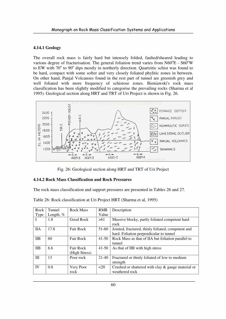
Monograph on Rock Mass Classification Systems and Applications
60
4.14.1 Geology
The overall rock mass is fairly hard but intensely folded, faulted/sheared leading to
various degree of fracturisation. The general foliation trend varies from N60oE - S60oW
to EW with 70o to 90o dips mostly in northerly direction. Quartzitic schist was found to
be hard, compact with some softer and very closely foliated phylitic zones in between.
On other hand, Panjal Volcanoes found in the rest part of tunnel are greenish grey and
well foliated with more frequency of schistose zones. Bieniawski's rock mass
classification has been slightly modified to categorise the prevailing rocks (Sharma et al
1995). Geological section along HRT and TRT of Uri Project is shown in Fig. 26.
Fig. 26: Geological section along HRT and TRT of Uri Project
4.14.2 Rock Mass Classification and Rock Pressures
The rock mass classification and support pressures are presented in Tables 26 and 27.
Table 26: Rock classification at Uri Project HRT (Sharma et al, 1995)
Rock
Type
Tunnel
Length, %
Rock Mass RMR
Value
Description
I 1.8 Good Rock >61 Massive blocky, partly foliated competent hard
rock
IIA 17.8 Fair Rock 51-60 Jointed, fractured, thinly foliated, competent and
hard. Foliation perpendicular to tunnel
IIB 60 Fair Rock 41-50 Rock Mass as that of IIA but foliation parallel to
tunnel
IIB 6.6 Fair Rock
(High Stress)
41-50 As that of IIB with high stress
III 13 Poor rock 21-40 Fractured or thinly foliated of low to medium
strength
IV 0.8 Very Poor
rock
<20 Crushed or shattered with clay & gauge material or
weathered rock
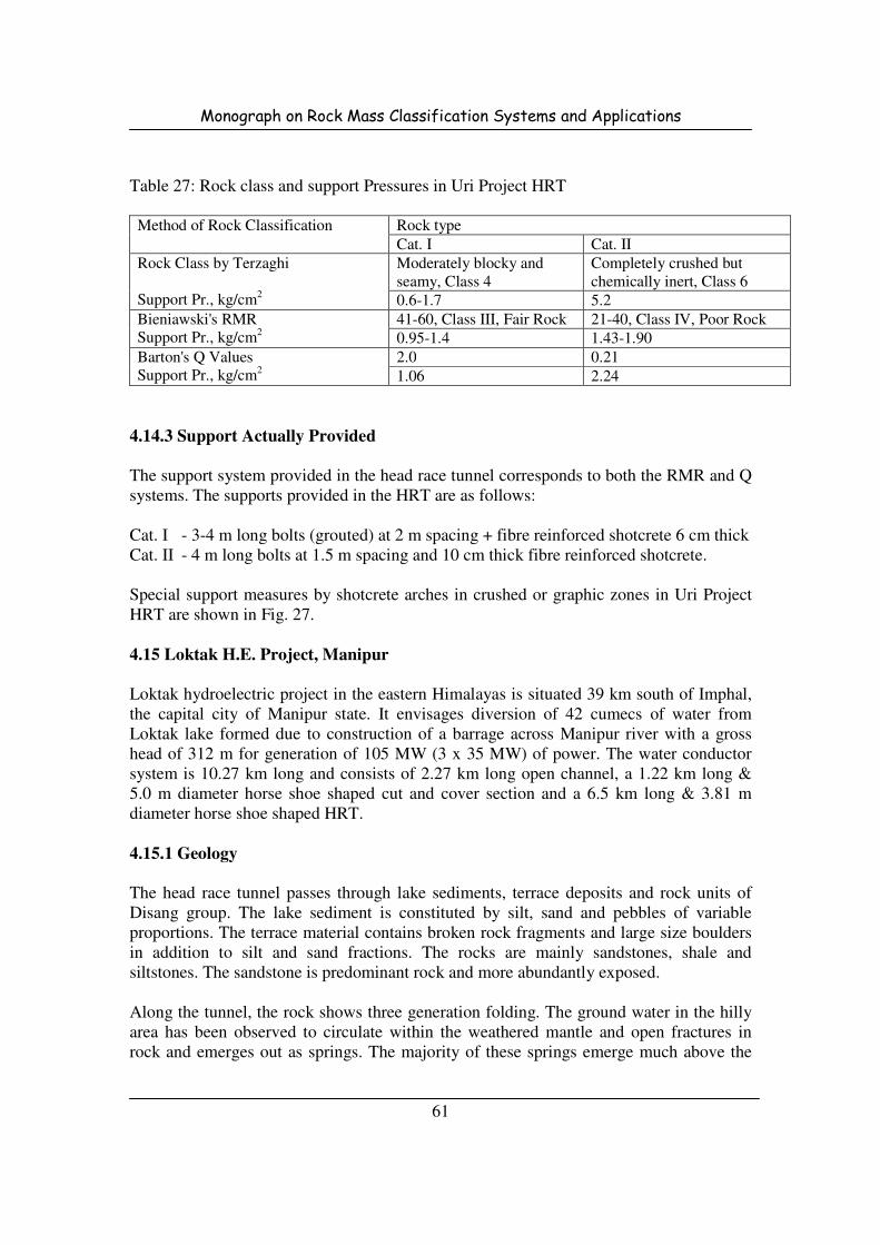
Monograph on Rock Mass Classification Systems and Applications
61
Table 27: Rock class and support Pressures in Uri Project HRT
Method of Rock Classification Rock type
Cat. I Cat. II
Rock Class by Terzaghi
Support Pr., kg/cm2
Moderately blocky and
seamy, Class 4
Completely crushed but
chemically inert, Class 6
0.6-1.7 5.2
Bieniawski's RMR
Support Pr., kg/cm2
41-60, Class III, Fair Rock 21-40, Class IV, Poor Rock
0.95-1.4 1.43-1.90
Barton's Q Values
Support Pr., kg/cm2
2.0 0.21
1.06 2.24
4.14.3 Support Actually Provided
The support system provided in the head race tunnel corresponds to both the RMR and Q
systems. The supports provided in the HRT are as follows:
Cat. I - 3-4 m long bolts (grouted) at 2 m spacing + fibre reinforced shotcrete 6 cm thick
Cat. II - 4 m long bolts at 1.5 m spacing and 10 cm thick fibre reinforced shotcrete.
Special support measures by shotcrete arches in crushed or graphic zones in Uri Project
HRT are shown in Fig. 27.
4.15 Loktak H.E. Project, Manipur
Loktak hydroelectric project in the eastern Himalayas is situated 39 km south of Imphal,
the capital city of Manipur state. It envisages diversion of 42 cumecs of water from
Loktak lake formed due to construction of a barrage across Manipur river with a gross
head of 312 m for generation of 105 MW (3 x 35 MW) of power. The water conductor
system is 10.27 km long and consists of 2.27 km long open channel, a 1.22 km long &
5.0 m diameter horse shoe shaped cut and cover section and a 6.5 km long & 3.81 m
diameter horse shoe shaped HRT.
4.15.1 Geology
The head race tunnel passes through lake sediments, terrace deposits and rock units of
Disang group. The lake sediment is constituted by silt, sand and pebbles of variable
proportions. The terrace material contains broken rock fragments and large size boulders
in addition to silt and sand fractions. The rocks are mainly sandstones, shale and
siltstones. The sandstone is predominant rock and more abundantly exposed.
Along the tunnel, the rock shows three generation folding. The ground water in the hilly
area has been observed to circulate within the weathered mantle and open fractures in
rock and emerges out as springs. The majority of these springs emerge much above the

Monograph on Rock Mass Classification Systems and Applications
62
tunnel grade and are principal source of water for streams draining the hill slopes.
Geological section of Loktak Hydel tunnel is shown in Fig. 28.
Fig. 27: Special support measures by shotcrete arches in crushed
or graphic zones in Uri Project Head Race Tunnel
Fig. 28: Geological section of Loktak Hydel tunnel

Monograph on Rock Mass Classification Systems and Applications
63
4.15.2 Rock Mass Classification and Rock Pressures
The rock pressures and rock mass classes are presented in Table 28.
Table 28: Rock class and support pressures in Loktak HRT
Method of Rock Classification Description
Rock Class by Terzaghi
Support Pr., kg/cm2
Highly Squeezing (Class 8)
6.1-11.6
Deere's Method, RQD
Support Pr., kg/cm2
5-25 (Highly Squeezing)
Very Very High, Upto 75 m of rock
Bieniawski's RMR
Support Pr., kg/cm2
Stand-up Time
10 (Very Poor)
1.17
Immediate Collapse
Barton's Q Values (Jethwa et al 1982)
Support Pr., kg/cm2, Proof
Pwall
0.023 (Very Poor Rock)
4.7
4.7
4.15.3 Support Actually Provided
The following supports have been provided in the head race tunnel:
• 3 m long bolts with a flexible shotcrete lining with wire mesh is provided as
temporary or immediate support
• Finally steel sets of 150 x150 mm size embedded in 30 cm thick M250 cement
concrete lining was provided as permanent support.
In this case no gap was left between shotcrete lining and steel supports. The steel
supports were designed to take entire squeezing rock pressure. Details of rock support in
Loktak Hydel tunnel are shown in Fig. 29.
4.16 Salal H.E. Project, J & K
Salal hydroelectric project is situated around 120 km south of Jammu in J & K state. The
tail race tunnel of the project consists of 12 m diameter & 2.6 km long horse shoe shaped.
TRT passes through various grades of dolomites of Lower Himalayas. While tunnelling,
no frequent tunnelling problems were encountered except a major collapse with water
inrush and gougy material. Tunnel was monitored by installation of load cells and closure
studs for evaluating steel supports.
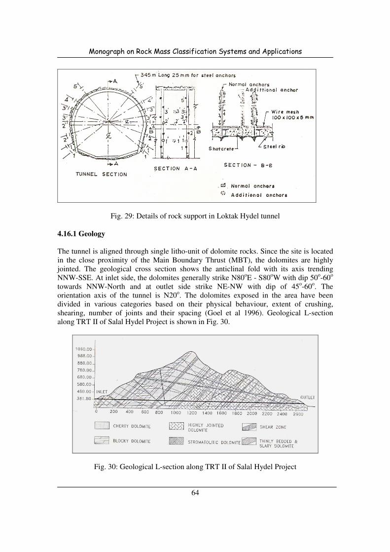
Monograph on Rock Mass Classification Systems and Applications
64
Fig. 29: Details of rock support in Loktak Hydel tunnel
4.16.1 Geology
The tunnel is aligned through single litho-unit of dolomite rocks. Since the site is located
in the close proximity of the Main Boundary Thrust (MBT), the dolomites are highly
jointed. The geological cross section shows the anticlinal fold with its axis trending
NNW-SSE. At inlet side, the dolomites generally strike N80oE - S80
oW with dip 50
o-60
o
towards NNW-North and at outlet side strike NE-NW with dip of 45o-60
o. The
orientation axis of the tunnel is N20o. The dolomites exposed in the area have been
divided in various categories based on their physical behaviour, extent of crushing,
shearing, number of joints and their spacing (Goel et al 1996). Geological L-section
along TRT II of Salal Hydel Project is shown in Fig. 30.
Fig. 30: Geological L-section along TRT II of Salal Hydel Project
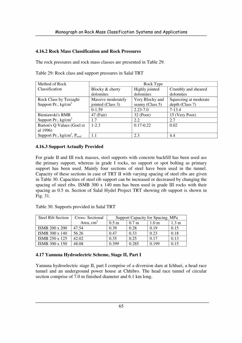
Monograph on Rock Mass Classification Systems and Applications
65
4.16.2 Rock Mass Classification and Rock Pressures
The rock pressures and rock mass classes are presented in Table 29.
Table 29: Rock class and support pressures in Salal TRT
Method of Rock
Classification
Rock Type
Blocky & cherty
dolomites
Highly jointed
dolomites
Crumbly and sheared
dolomites
Rock Class by Terzaghi
Support Pr., kg/cm2
Massive moderately
jointed (Class 3)
Very Blocky and
seamy (Class 5)
Squeezing at moderate
depth (Class 7)
0-1.59 2.23-7.0 7-13.4
Bieniawski's RMR
Support Pr., kg/cm2
47 (Fair) 32 (Poor) 15 (Very Poor)
1.7 2.2 2.7
Barton's Q Values (Goel et
al 1996)
Support Pr., kg/cm2, Proof
1-2.3
0.17-0.22 0.02
1.1 2.3 4.4
4.16.3 Support Actually Provided
For grade II and III rock masses, steel supports with concrete backfill has been used ass
the primary support, whereas in grade I rocks, no support or spot bolting as primary
support has been used. Mainly four sections of steel have been used in the tunnel.
Capacity of these sections in case of TRT II with varying spacing of steel ribs are given
in Table 30. Capacities of steel rib support can be increased or decreased by changing the
spacing of steel ribs. ISMB 300 x 140 mm has been used in grade III rocks with their
spacing as 0.5 m. Section of Salal Hydel Project TRT showing rib support is shown in
Fig. 31.
Table 30. Supports provided in Salal TRT
Steel Rib Section Cross- Sectional
Area, cm2
Support Capacity for Spacing, MPa
0.5 m 0.7 m 1.0 m 1.3 m
ISMB 200 x 200 47.54 0.39 0.28 0.19 0.15
ISMB 300 x 140 56.26 0.47 0.33 0.23 0.18
ISMB 250 x 125 42.02 0.35 0.25 0.17 0.13
ISMB 300 x 150 48.08 0.399 0.285 0.199 0.15
4.17 Yamuna Hydroelectric Scheme, Stage II, Part I
Yamuna hydroelectric stage II, part I comprise of a diversion dam at Ichhari, a head race
tunnel and an underground power house at Chhibro. The head race tunnel of circular
section comprise of 7.0 m finished diameter and 6.1 km long.

Monograph on Rock Mass Classification Systems and Applications
66
Fig. 31: Section of Salal Hydel Project TRT showing rib support
4.17.1 Geology
The rock type comprise of slates interbedded with limestones. The limestones belonging
to Bansa stage of Chandpur are hard and tough, whereas the limestones of Dhaira stage of
the Mandhalis are relatively sift and interbedded with slates. The alignment of the tunnel
is N60oW to S60
oE direction, which is almost at right angle to the regional strike of local
variations. Geological L-section of Ichhari-Chhibro HRT is shown in Fig. 32.
Fig. 32: Geological L-section of Ichhari-Chhibro HRT

Monograph on Rock Mass Classification Systems and Applications
67
4.17.2 Rock Mass Classification and Rock Pressures
The rock load varies between 0.25 B to 0.5 B as per Terzaghi's rock classification. A rock
load of 0.375 B (0.7 kg/cm2) has been taken for the design of supports. The rock
pressures by modified classification by Singh come out to be between 0.4 to 0.7 kg/cm2.
4.17.3 Support Actually Provided
For supporting the rock load, steel supports of ISMB 250 x 125 mm size at a spacing of
1.5 m have been provided. In greater part of the tunnel, the support was not required.
Rock bolts have been provided for jointed rocks. Adopted rock support for Ichhari -
Chhibro HRT is shown in Fig. 33.
4.18 Yamuna Hydroelectric Scheme, Stage II, Part II
Yamuna hydroelectric stage II, part II in Outer Himalayas envisages utilisation of 64 m
drop available between tail race of Chhibro underground power house and power house
of Khodri. Chhibro-Khodri tunnel 5.6 km long and 7.5 m finished diameter is constructed
to carry water from Chhibro power house for generation of 120 MW of power.
Fig. 33: Adopted rock support for Ichhari - Chhibro HRT
4.18.1 Geology
Chhibro-Khodri head race tunnel passes through Nahans constituted of bands of
sandstones, siltstones and claystones from Khodri end in about 3.0 km length. From
Chhibro end, the tunnel passes through Mandhalis consisting of quartzites and slates in a
length of about 2.3 km. In between these two formations about 300 m, length thrust zone
bounded by Krol and Nahan thrusts and comprising of crushed, sheared and highly
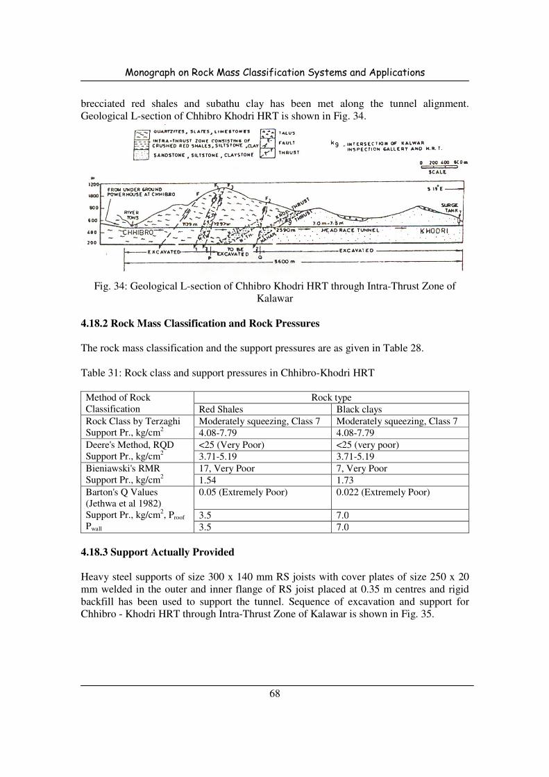
Monograph on Rock Mass Classification Systems and Applications
68
brecciated red shales and subathu clay has been met along the tunnel alignment.
Geological L-section of Chhibro Khodri HRT is shown in Fig. 34.
Fig. 34: Geological L-section of Chhibro Khodri HRT through Intra-Thrust Zone of
Kalawar
4.18.2 Rock Mass Classification and Rock Pressures
The rock mass classification and the support pressures are as given in Table 28.
Table 31: Rock class and support pressures in Chhibro-Khodri HRT
Method of Rock
Classification
Rock type
Red Shales Black clays
Rock Class by Terzaghi
Support Pr., kg/cm2
Moderately squeezing, Class 7 Moderately squeezing, Class 7
4.08-7.79 4.08-7.79
Deere's Method, RQD
Support Pr., kg/cm2
<25 (Very Poor) <25 (very poor)
3.71-5.19 3.71-5.19
Bieniawski's RMR
Support Pr., kg/cm2
17, Very Poor 7, Very Poor
1.54 1.73
Barton's Q Values
(Jethwa et al 1982)
Support Pr., kg/cm2, Proof
Pwall
0.05 (Extremely Poor)
0.022 (Extremely Poor)
3.5 7.0
3.5 7.0
4.18.3 Support Actually Provided
Heavy steel supports of size 300 x 140 mm RS joists with cover plates of size 250 x 20
mm welded in the outer and inner flange of RS joist placed at 0.35 m centres and rigid
backfill has been used to support the tunnel. Sequence of excavation and support for
Chhibro - Khodri HRT through Intra-Thrust Zone of Kalawar is shown in Fig. 35.
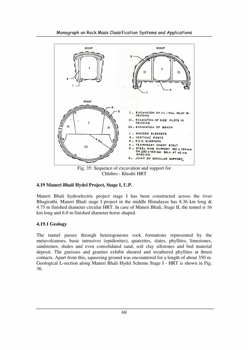
Monograph on Rock Mass Classification Systems and Applications
69
Fig. 35: Sequence of excavation and support for
Chhibro - Khodri HRT
4.19 Maneri Bhali Hydel Project, Stage I, U.P.
Maneri Bhali hydroelectric project stage I has been constructed across the river
Bhagirathi. Maneri Bhali stage I project in the middle Himalayas has 8.36 km long &
4.75 m finished diameter circular HRT. In case of Maneri Bhali, Stage II, the tunnel is 16
km long and 6.0 m finished diameter horse shaped.
4.19.1 Geology
The tunnel passes through heterogeneous rock formations represented by the
metavolcanoes, basic intrusives (epidiorites), quatrzites, slates, phyllites, limestones,
sandstones, shales and even consolidated sand, soil clay siltstones and bed material
deposit. The gneisses and granites exhibit sheared and weathered phyllites at thrust
contacts. Apart from this, squeezing ground was encountered for a length of about 350 m.
Geological L-section along Maneri Bhali Hydel Scheme Stage I - HRT is shown in Fig.
36.

Monograph on Rock Mass Classification Systems and Applications
70
Fig. 36: Geological L-section along Maneri Bhali Hydel Scheme Stage I - HRT
4.19.2 Rock Mass Classification and Rock Pressures
The rock mass classification and the support pressures are as given in Table 32.
Table 32: Rock class and support pressures in Maneri Bhali Stage I, HRT
Method of Rock
Classification
Rock type
Moderately
fractured quartzites
Foliated
metabasics
Sheared
metabasics
Highly fractured
quartzites
Rock Class by Terzaghi
Support Pr., kg/cm2
Rock Class 4 Rock Class 4 Rock Class 6 Rock Class 7
0.3-0.8 0.3-0.8 2.77 2.77-5.29
Deere's Method, RQD
Support Pr., kg/cm2
75 (Fair to Good) 82, Good Rock 60, Fair Rock 60, Fair Rock
0.48 0.36-0.72 0.72-1.56 0.72-1.56
Bieniawski's RMR
Support Pr., kg/cm2
58 (Fair rock) 59, Fair rock 49, Fair rock 38, Poor rock
0.61 0.60 0.74 0.90
Barton's Q Values
(Jethwa et al 1982)
Support Pr., kg/cm2,
Proof
Pwall
3.0-6.0
3.4-6.8 0.3-3.3 0.5
0.5-0.7 0.5-0.7 0.7-1.8 1.6
0.1-0.2 0.1-0.2 0.2-1.2 1.1
4.19.3 Support Actually Provided
Maneri Bhali HRT has been provided with ISMB 250 x 125 steel rib supports.
Depending upon the type of rock quality, the rib spacing has been varied from 50 cm to
120 cm. Steel rib supports of 150 x 150 mm has also been used at a spacing of 120 cm for
rock load of 0.375 B and 80 cm for rock load 1.0 B, respectively. Rock support system
adopted in Maneri Bhali Hydel Scheme Stage I - HRT is shown in Fig. 37.
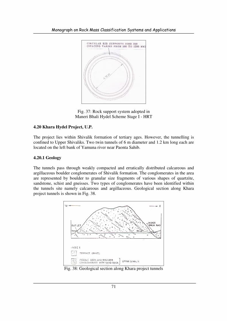
Monograph on Rock Mass Classification Systems and Applications
71
Fig. 37: Rock support system adopted in
Maneri Bhali Hydel Scheme Stage I - HRT
4.20 Khara Hydel Project, U.P.
The project lies within Shivalik formation of tertiary ages. However, the tunnelling is
confined to Upper Shivaliks. Two twin tunnels of 6 m diameter and 1.2 km long each are
located on the left bank of Yamuna river near Paonta Sahib.
4.20.1 Geology
The tunnels pass through weakly compacted and erratically distributed calcareous and
argillaceous boulder conglomerates of Shivalik formation. The conglomerates in the area
are represented by boulder to granular size fragments of various shapes of quartzite,
sandstone, schist and gneisses. Two types of conglomerates have been identified within
the tunnels site namely calcareous and argillaceous. Geological section along Khara
project tunnels is shown in Fig. 38.
Fig. 38: Geological section along Khara project tunnels
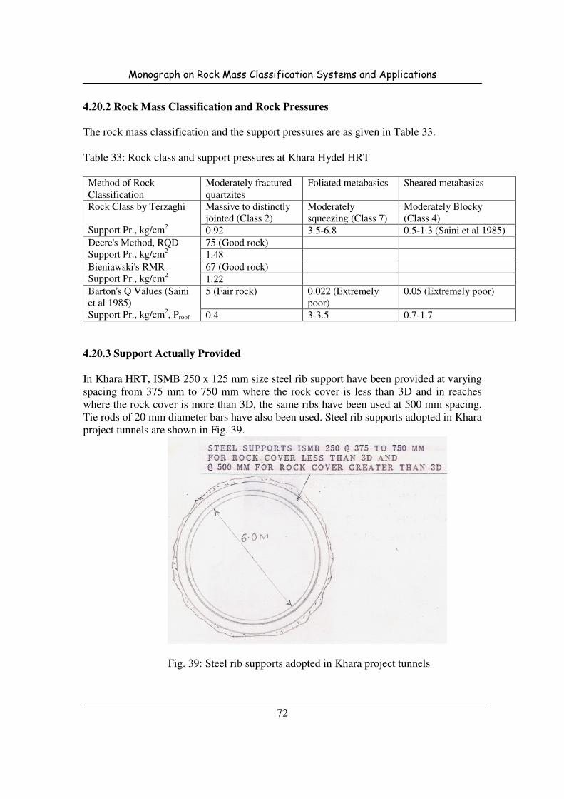
Monograph on Rock Mass Classification Systems and Applications
72
4.20.2 Rock Mass Classification and Rock Pressures
The rock mass classification and the support pressures are as given in Table 33.
Table 33: Rock class and support pressures at Khara Hydel HRT
Method of Rock
Classification
Moderately fractured
quartzites
Foliated metabasics Sheared metabasics
Rock Class by Terzaghi
Support Pr., kg/cm2
Massive to distinctly
jointed (Class 2)
Moderately
squeezing (Class 7)
Moderately Blocky
(Class 4)
0.92 3.5-6.8 0.5-1.3 (Saini et al 1985)
Deere's Method, RQD
Support Pr., kg/cm2
75 (Good rock)
1.48
Bieniawski's RMR
Support Pr., kg/cm2
67 (Good rock)
1.22
Barton's Q Values (Saini
et al 1985)
Support Pr., kg/cm2, Proof
5 (Fair rock)
0.022 (Extremely
poor)
0.05 (Extremely poor)
0.4 3-3.5 0.7-1.7
4.20.3 Support Actually Provided
In Khara HRT, ISMB 250 x 125 mm size steel rib support have been provided at varying
spacing from 375 mm to 750 mm where the rock cover is less than 3D and in reaches
where the rock cover is more than 3D, the same ribs have been used at 500 mm spacing.
Tie rods of 20 mm diameter bars have also been used. Steel rib supports adopted in Khara
project tunnels are shown in Fig. 39.
Fig. 39: Steel rib supports adopted in Khara project tunnels

Monograph on Rock Mass Classification Systems and Applications
73
4.21 Tehri Hydroelectric Project, U.P.
Tehri dam project, across river Bhagirathi, has been constructed with a 260 m high
rockfill dam and underground power house in two stages. The underground works mainly
comprise of diversion tunnels, two on each bank, four HRT's and underground
powerhouse complex. The diversion tunnels of 11.0 m diameter horse shoe shaped are
designed to pass a routed construction stage flow of nearly 7500 cumecs.
4.21.1 Geology
The rock type in tunnels T1 and T2 comprise of grade II and II whereas in tunnels T3 and
T4, phyllites of grade I, grade II and grade III in about 30%, 60% and 10% of the tunnel
length, respectively, have been encountered. Geological sections along left bank and right
bank Tehri dam diversion tunnels are shown in Figs. 40 and 41.
Fig. 40: Geological section along left bank Tehri dam diversion tunnels
Fig. 41: Geological section along right bank Tehri dam diversion tunnels
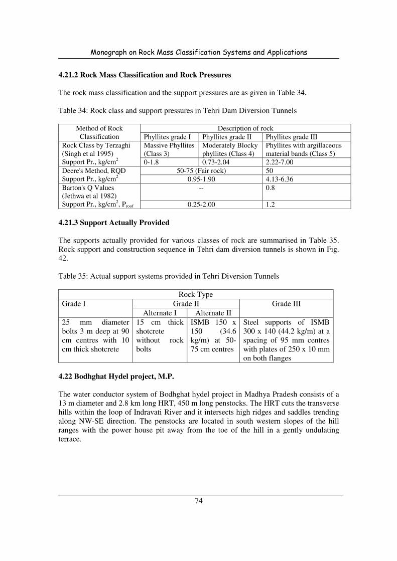
Monograph on Rock Mass Classification Systems and Applications
74
4.21.2 Rock Mass Classification and Rock Pressures
The rock mass classification and the support pressures are as given in Table 34.
Table 34: Rock class and support pressures in Tehri Dam Diversion Tunnels
Method of Rock
Classification
Description of rock
Phyllites grade I Phyllites grade II Phyllites grade III
Rock Class by Terzaghi
(Singh et al 1995)
Support Pr., kg/cm2
Massive Phyllites
(Class 3)
Moderately Blocky
phyllites (Class 4)
Phyllites with argillaceous
material bands (Class 5)
0-1.8 0.73-2.04 2.22-7.00
Deere's Method, RQD
Support Pr., kg/cm2
50-75 (Fair rock) 50
0.95-1.90 4.13-6.36
Barton's Q Values
(Jethwa et al 1982)
Support Pr., kg/cm2, Proof
--
0.8
0.25-2.00 1.2
4.21.3 Support Actually Provided
The supports actually provided for various classes of rock are summarised in Table 35.
Rock support and construction sequence in Tehri dam diversion tunnels is shown in Fig.
42.
Table 35: Actual support systems provided in Tehri Diversion Tunnels
Rock Type
Grade I Grade II Grade III
Alternate I Alternate II
25 mm diameter
bolts 3 m deep at 90
cm centres with 10
cm thick shotcrete
15 cm thick
shotcrete
without rock
bolts
ISMB 150 x
150 (34.6
kg/m) at 50-
75 cm centres
Steel supports of ISMB
300 x 140 (44.2 kg/m) at a
spacing of 95 mm centres
with plates of 250 x 10 mm
on both flanges
4.22 Bodhghat Hydel project, M.P.
The water conductor system of Bodhghat hydel project in Madhya Pradesh consists of a
13 m diameter and 2.8 km long HRT, 450 m long penstocks. The HRT cuts the transverse
hills within the loop of Indravati River and it intersects high ridges and saddles trending
along NW-SE direction. The penstocks are located in south western slopes of the hill
ranges with the power house pit away from the toe of the hill in a gently undulating
terrace.
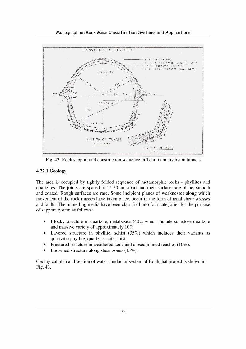
Monograph on Rock Mass Classification Systems and Applications
75
Fig. 42: Rock support and construction sequence in Tehri dam diversion tunnels
4.22.1 Geology
The area is occupied by tightly folded sequence of metamorphic rocks - phyllites and
quartzites. The joints are spaced at 15-30 cm apart and their surfaces are plane, smooth
and coated. Rough surfaces are rare. Some incipient planes of weaknesses along which
movement of the rock masses have taken place, occur in the form of axial shear stresses
and faults. The tunnelling media have been classified into four categories for the purpose
of support system as follows:
• Blocky structure in quartzite, metabasics (40% which include schistose quartzite
and massive variety of approximately 10%.
• Layered structure in phyllite, schist (35%) which includes their variants as
quartzitic phyllite, quartz sericiteschist.
• Fractured structure in weathered zone and closed jointed reaches (10%).
• Loosened structure along shear zones (15%).
Geological plan and section of water conductor system of Bodhghat project is shown in
Fig. 43.
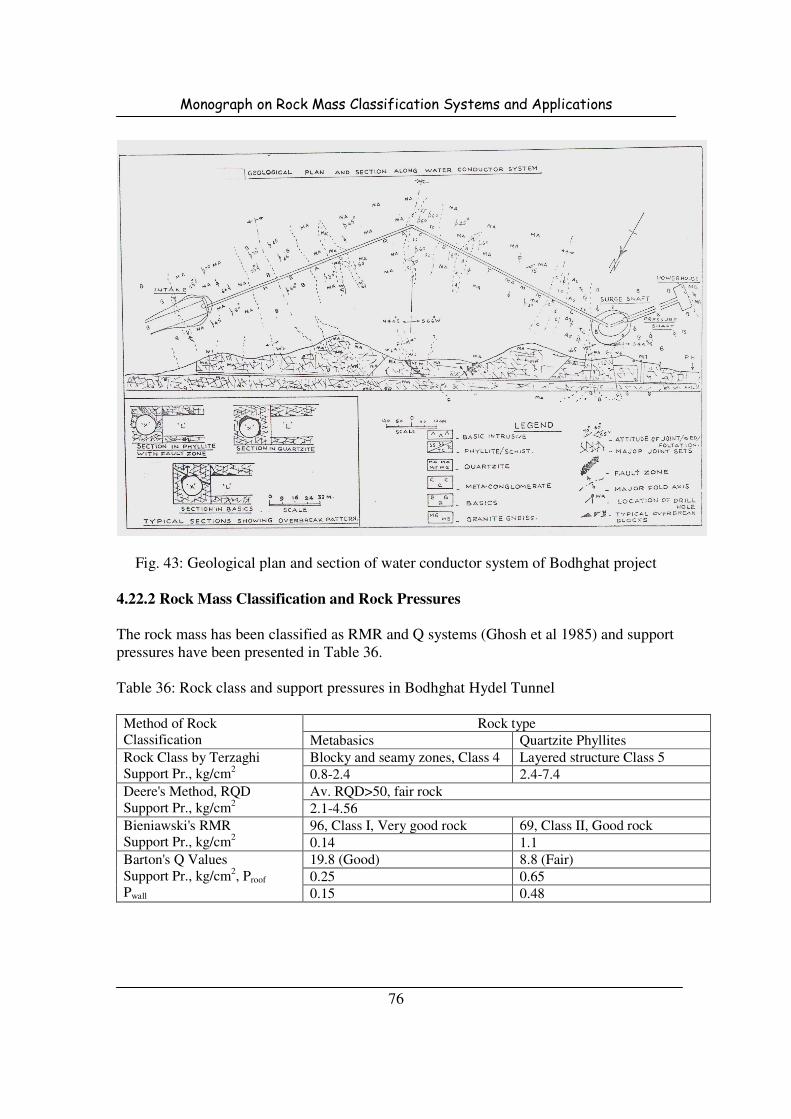
Monograph on Rock Mass Classification Systems and Applications
76
Fig. 43: Geological plan and section of water conductor system of Bodhghat project
4.22.2 Rock Mass Classification and Rock Pressures
The rock mass has been classified as RMR and Q systems (Ghosh et al 1985) and support
pressures have been presented in Table 36.
Table 36: Rock class and support pressures in Bodhghat Hydel Tunnel
Method of Rock
Classification
Rock type
Metabasics Quartzite Phyllites
Rock Class by Terzaghi
Support Pr., kg/cm2
Blocky and seamy zones, Class 4 Layered structure Class 5
0.8-2.4 2.4-7.4
Deere's Method, RQD
Support Pr., kg/cm2
Av. RQD>50, fair rock
2.1-4.56
Bieniawski's RMR
Support Pr., kg/cm2
96, Class I, Very good rock 69, Class II, Good rock
0.14 1.1
Barton's Q Values
Support Pr., kg/cm2, Proof
Pwall
19.8 (Good) 8.8 (Fair)
0.25 0.65
0.15 0.48

Monograph on Rock Mass Classification Systems and Applications
77
5.0 OBSERVED SUPPORT PRESSURES
The case studies of tunnels for which the actual supports provided were available, support
pressures accommodated were determined using the following equations:
lc
bf
sbmxSS
TP = for rock bolts ….. (15)
( )
−−= −
2
2
. 12
i
ciconcc
scmxr
trP
σ for shotcrete ….. (16)
( )
−
+−+
=
θθ
σ
cos12
32
3
xtrxAISr
IAP
bissi
ysss
ssmx
for steel supports ….. (17)
Where
Psbmx = Maximum support pressure accommodated by rock bolts.
Tbf = Ultimate load of bolts from pull out tests
Sc = Circumferential rock bolt spacing
Sl = Longitudinal rock bolt spacing
Pscmx = Maximum support pressure accommodated by shotcrete
σc-conc = Uniaxial compressive strength of concrete or shotcrete
ri = Internal radius of opening
tc = Thickness of shotcrete
Pssbmx = Maximum support pressure accommodated by steel supports
x = Depth of section of steel set
As = Cross sectional area of steel set
Is = Moment of inertia of steel section
σys = Yield strength of steel
S = Steel set spacing along tunnel axis
θ = Half angle between blocking points
tb = Thickness of block
Instrumented data for support pressures or rock loads was available in some of the
tunnels. These observed support pressures have also been presented in Table 36 along
with the accommodated support pressures.

Monograph on Rock Mass Classification Systems and Applications
78
Table 36: Support pressures accommodated by actual supports and observed by
instrumentation
Sl.
No.
Name of the project Rock type Accommodated
support pressure by
actual supports,
kg/cm2
Observed
support
pressure,
kg/cm2
1 Ramganga Project -
Tunnels
Sand rock & clay shale 3.41-6.71 -
2 Narmada Sagar Project -
Pressure shafts
Quartzite 4.59 -
3 Giri Project - HRT Slates (Squeezing) 5.29-16.04 2.0
Phyllites (Squeezing) 1.7
4 Loktak Project - HRT Sandstone, shale and siltstone - 5.4
5 Uri project - HRT Quartzitic schist 2.70 -
Panjal volcanoes 4.54 -
6 Salal Project - TRT Sheared dolomite 4.71 1.1
7 Yamuna Stage I, Part I -
HRT
Shales with bands of quartzite
& limestones
3.24 -
8 Yamuna Stage II, Part II -
Chhibro Khodri HRT
Red shales 17.17 10.8
Black clays 3.2
9 Maneri Bhali Project -
HRT
Moderately fractured
quartzites
11.30 0.6
Foliated metabasics 8.48 0.8
Sheared metabasics 6.59 2.0
Highly fractured quartzites 15.82 -
10 Khara Project - HRT Phyllites 7.89 -
Argillaceous conglomerates 15.77 0.75-3.0
Calcareous conglomerates 11.83 -
11 Tehri Project, diversion
tunnels
Phyllite Grade I 4.83 0.25
Phyllite Grade II 5.38 0.52
Phyllite Grade III 3.51 1.24
12 Tala Project - HRT Highly shattered, moderate to
highly weathered, folded
interbands of quartzite,
amphibolites and biotite
schist (highly squeezing)
6.0-7.0 upto 17.08
6.0 COMPARISON OF ROCK CLASSIFICATION METHODS
Various rock mass classification methods have been used to classify rock mass and at
various hydro power projects in India and Bhutan. In old projects rock classification and
supports in these projects were based upon Terzaghi’s method of rock classification
which recommends steel rib arch supports. This method is too much conservative as it
anticipates high rock loads which results to heavy supports leading to wastage of time,
material and funds. With advancement in developments, systematic rock classifications
came into existence.

Monograph on Rock Mass Classification Systems and Applications
79
Deere’s method was the first systematic approach in this direction. Wickham’s RSR
concept was the first complete rock mass classification system with introduction of rating
system. The classification systems developed by Bieniawski (RMR) and Barton (Q
System) takes into account various rock mass parameters. These classification systems
have been adopted world wide including India. Although these methods contain a few
case histories of Himalayan Rocks, these systems have been successfully applied in
various projects in India. Sometimes these methods need a slight modification as RMR
method was adopted in Uri Project in Jammu and Kashmir. It would be better to combine
experience and techniques for better results. As visual observations are applied in
evaluation of Q and RMR, therefore field experience plays as a key role in classification
of rock mass as well as in selection of supports.
With regard to support pressures, RMR and Q systems seem to be in close agreement
with observed support pressures whereas all the other methods give high anticipated
support pressures. Though correlations between different rock classifications i.e. RSR,
RMR and Q in particular exist for calculating the support pressures, but actual support
pressures from instrumentation is advisable.
Apart from rock classification, Q system provides thumb rules for selection and the
extent of supports and charts are available. These supports can be simulated with
numerical methods. In view of the wide range of case histories and subsequent
modifications in Q system since its inception, it can be used with more confidence. Q
system incorporates the latest developments in construction of underground structures
such as tunnelling methods whether boring or TBM tunnels, recent rock support concepts
such as flexible reinforced shotcrete arches in place of conventional heavy and rigid steel
supports etc.
RECOMMENDATIONS
Even though the developments have taken place in the field of rock engineering, the rock
support classification approach as well as the support system design is empirical. Hence,
the available classification systems need to be dealt carefully. These classifications were
not intended to replace analytical studies, field observations and measurements. The
judgement of the field geologists and the engineers is more significant. Although
guidelines for support systems exist, but the final decision should be taken by the site in-
charge regarding the nature and extent of support systems. Himalayan rocks are posing
different problems which need to be dealt with experience. Exploration during the
detailed project report (DPR) stage helps in assessment of geological strata to be
encountered. Therefore, holes should be drilled at regular intervals along the tunnel
alignment and at critical locations so that detailed geological information can be
gathered. Instrumentation should be made an essential part in underground excavations.
Instrumented data can be used to study the behaviour of structures in and on rock. In the
light of the above, RMR and Q systems seems to have some advantages over other
Monograph on Rock Mass Classification Systems and Applications
80
methods for use in rock classifications, but rock supports determined recommended by
these methods should be validated through numerical modelling methods also.
REFERENCES
Agarwal K.B., Singh Bhawani, Swami Saran, Jain P.K., Chandra S., Awasthi A.K. and
Prem Dayal (1985), "A case study with reference to Geotechnical Aspects for an
underground power house of Sanjay Vidyut Pariyojna - Bhaba", University of Roorkee,
Roorkee
Ahmad, M.J. (1996), "Rock mass improvement and support systems for pressure tunnels
- Narmada Sagar project, Distt. Khandwa, M.P.", Recent Advances in Tunnelling
technology, New Delhi, pp 275-280
Barton, N, Lien, R. And Lunde, J. (1974). Engineering classification of Rock Masses for
the Design of Tunnel Support, Rock Mech. Vol. 6, No. 4, pp. 189-236.
Barton, N. (1988). Rock mass classification and tunnel reinforcement selection using Q-
system”, Proc. Symp. Rock Class. Eng. Purp., ASTM 984, Philadelphia, pp. 59-88.
Baczynski, N. (1980) “Rock mass characterization and its application to Assessment of
unsupported underground Openings”, Ph.D. thesis, University of Melbourne, pp.233.
Bhasin R., Barton N., Grimstad E. and Chryssanthakis P. (1996a), "Engineering
geological characterisation of low strength anisotropic rocks in Himalayan Region for
assessment of tunnel support", Recent Advances in Tunnelling technology, New Delhi,
pp 157-181.
Bhasin R.K., Singh R.B., Dhawan A.K. and Sharma V.M. (1996b), "Geotechnical
evaluation and review of remedial measures in limiting deformations in distressed zones
in a power house cavern", Conference on design and construction of underground
structures, New Delhi, pp 145-161.
Bieniawski, Z. T. (1973), “Engineering classification of jointed rock masses
transactions”, South African Institution of Carl Engineers, Vol. 15, No. 12, pp. 335-344.
Bieniawski, Z.T. (1976), "Rock mass classification in rock engineering", Proceeding
Symposium on Exploration for Rock Engineering, ed. Z.T. Bieniawski, A.A. Balkema
Rotterdam, pp. 97-106.
Bieniawski, Z.T. (1979), "The geomechanics classification in rock engineering
applications", Proc. 4th Int. Congress Rock Mech. , ISRM, Montreaux, A.A. Balkema ,
Rotterdam , Vol. 2 , pp. 51-58.

Monograph on Rock Mass Classification Systems and Applications
81
Bieniawski, Z.T. (1989), "Engineering rock mass classifications", John Wiley and Sons,
New York, 251p.
Char S.A., Menon K.K. and Sood P.K. (1988), "Geotechnical aspects affecting the design
and construction of underground structure for Chukha hydroelectric project", Proc. ISRM
Symp. Rock Mech. & Power Plants, Madrid, 1, pp 299-308.
Coates D.F. (1963), "Rock mechanics applied to the design of underground installations
to resist ground shock from Nuclear blasts", Proc. 5th
Symp. on Rock Mechanics,
Minneapolis, 1962, pp 525-562.
Deere D.U. (1963), "Technical description of rock cores for engineering purposes",
Felsmechanik and Ingenienrgeologic, Vol. 1, No. 1, pp 16-22.
Deere D.U., Hendron A.J., Patton F.D. and Cording E.J. (1967), " Design of sorface and
near surface construction in rock", Failure and breakage of rock, Proc. 8th
U.S. Symp.
Rock mech., (Ed. A. Fairhurst), New York: Soc. Min. Engs., Am. Inst. Min. Metall.,
petrolm. Engs., pp 237-302.
Deere D.U., Peck R.B., Monsees J.E. and Schmidt (1969), "Design of tunnel; liners and
support systems", Report prepared by University of Illinois Urbana, for the office of High
Speed Ground Transportation, NTIS Publication PB 183-799.
Deere D.U. and Deere, D.W. (1988), "The RQD index in practice", Proc. Symp. Rock
Classif. Eng. Purp., ASTM 984, ), Philadelphia, pp. 91-100.
Deere D.U. (1989), "Rock quality designation (RQD) after 20 years", U.S. Army Corps
Engs. Contract Report GL-89-1, Vicksburg, MS: Waterways Experimental Station.
Dube A.K., Singh B. and Singh Bhawani (1986), "Study of squeezing pressure
phenomenon in a tunnel - I and II", Tunnelling and Underground Space Technology, 1,
pp 35-48.
Franklin J.A. (1975), "Safety and economic of tunnelling", Proc. 10th Canadian Rock
Mech. Symp., Kingstone, pp 27-53.
Ghose A.K. and Raju N.M. (1981), "Characterisation of rock mass vis-a-vis application
of rock bolting in Indian coal measires, Proc. 22nd
U.S. Symp. on Rock Mech., MIT,
Cambridge MA, pp 422-427.
Ghosh D.K. and Ahmad M.J. (1985), "Geotechnical consideration in forecasting
tunnelling conditions for the water conductor system of Bodhghat Hydel project", IIIrd
Symp. on Rock Mech., Roorkee, pp 36-41.
Monograph on Rock Mass Classification Systems and Applications
82
Goel R.K, Swarup S.K., Dube A.K. and Kumar P. (1996), "Tunnelling through blocky
rock masses of Lower Himalayas - A case study", Recent Advances in Tunnelling
Technology, New Delhi, pp 241-247.
Grimstad E. and Barton N. (1988), "Design and methods of rock support", Norwegian
Tunnelling Today, Norwegian Soil and Rock Engg. Association, Pub. 5, pp 59-64.
Grimstad E. and Barton N. (1993), "Updating of Q system for NMT", Proc. Int. Symp. on
Sprayed Conc., Fargenes, Norway, Norwegian Concrete Association, Oslo.
Gupta O.P. (1968), "Evaluation of rock loads for design of steel supports for tunnels",
Indian Journal of Power and River Valley Development, March Edition.
Hari Dev (1997), "Design Criteria for supports and lining of underground structures for
water resources projects - some case studies", M.E. Dissertation, WRDTC, University of
Roorkee.
Hoek E. and Brown E.T. (1980), "Underground excavations in rock", Institution of
Mining and Metallurgy, London, 527 pp.
ISRM (1981), "Basic Technical Description of Rock Masses", Int. J. Rock Mech. Min.
Sci., Vol. 18, pp. 85-110.
Jethwa J.L., Dube A.K., Singh B. and Mithal R.S. (1982), "Evaluation of methods for
tunnel support design in squeezing rock conditions", Proc. 4th
Int. Cong. Assn. Eng. Geol.
Delhi, pp.125-134.
Kaisar P.K., Mackay C. and Gale A.D. (1986), "Evaluation of rock classifications at B.C.
rail tumbler ridge tunnel", Rock Mech. Rock Engg. 19, pp 205-234.
Kendorski F., Comminger R., Bieniawski Z.T. and Slommer E. (1983), "Rock mass
clasification for Block Caving mine drift support", Proc. 5th
Int. Congr. Rock Mech. ISR,
Melbourne, pp B51-B63.
Kindybinski (1979), "Experience with rock penetrometers for mine rock stability
predictions", Proc. 4th Int. Congr. Rock mech., ISRM, Montreux, pp 293-301.
Laubscher, D.H. (1977), "Geomechanics classifications of jointed rock masses - mining
applications", Trans. Inst. Min. Metall.Sect. A 86, pp.A1-A7.
Lauffer H. (1958), "Gebirgsklassifizeirung fur den stollenbau", Geologie and Bauwesen,
Vol. 24, No. 1, pp 46-51.
Merritt A.H. (1972), "Geologic prediction for underground excavations", Proc. North
American Rapid Excav. Tunnelling Conf., Chicago, (Eds. K.S. Lane and L.A. garfield) 1,
New York: Soc. Min. Engs., Am. Inst. Min. Metall., petrolm. Engs., 115-132.
Monograph on Rock Mass Classification Systems and Applications
83
Nakao K., Gihoshi S. and Koyama S. (1983), "Statistical reconsiderations on the
parameters for the geomechanics classification", Proc. 5th Int. Congr. Rock Mech., ISRM,
Melbourne, pp B13-16.
Oliver H.J. (1979), "Applicability of the geomechanics classification to the Orange - Fish
tunnel rock masses", Civ. Engg. S. Africa 21, pp 179-185.
Pacher F., Rabcewicz L. and Golser J. (1974), "Zum der seitigen Stand der
Gebirgsklassifizierung in Stollen-und Tunnelbau”, Proc. XXII Geomech. Colloq.,
Salzburg, pp 51-58.
Palmstrom A. (1982), "The volumetric joint count - a useful and simple measure of the
degree of rock jointing", Proc. 4th
Congr. Int. Assn. Engg. Geol., Delhi 5, 221-228.
Protodyakonov M.M. (1974), "Klassifikacija gornych porod", Tunnels Ouvrages
Souterrains 1, pp 31-34.
Ritter, W (1879), "Die Statik der Tunnelgewolbe", Berlin: Springer.
Rutledge J.C. and Preston R.L. (1978), "Experience with engineering classifications of
rock", Proc. Int. Tunnelling Symp., Tokyo, pp A3 1-37.
Saini G.S., Goel R.K. and Dube A.K. (1985), "Geotechnical assessment and behaviour of
tunnelling media at Khara project tunnels", IIIrd
Symp. on Rock Mech., Roorkee, pp 69-
77.
Serafim J.L. and Pereira J.P. (1983), "Considerations for geomechanics classification of
Bieniawski", Proc. Int. Symp. Engineering Geology and Underground Construction,
Lisbon, Vol 1, pp II.33-42, LNEC, Lisbon.
Sharma Brijendra and Sethi Rajeev (1994a), "Design of water conductor system of
Chamera Project", Indian Journal of Power and River Valley Development, May-June
Edition, pp 138-147.
Sharma Brijendra and Sethi Rajeev (1994b), "Design and excavation of underground
power house complex - some special features", Indian Journal of Power and River Valley
Development, May-June Edition, pp 148-158.
Sharma Kultar, hegde U.V. and Sayeed Imran (1995), "Tunnelling and adopted support
measures in fair to poor rock conditions of Kashmir Himalayas", Conference on design
and construction of underground structures, New Delhi, pp 495-508.
Singh Bhawani, Jethwa J.L. and Dube A.K. (1985a), "A Classification for support
pressure in tunnels and caverns", Jour. of Rock Mechanics and Tunnelling Technology
(India), Vol. 1, No. 1, pp 13-24.

Monograph on Rock Mass Classification Systems and Applications
84
Singh Bhawani, Jethwa J.L, Dube A.K. and Singh B. (1992), "Correlation between
observed support pressure and rock mass quality", Tunnelling and Underground Space
Technology, Vol. 7, No. 1, pp 59-74.
Singh Narinder and Agarwal Sanjay (1995b), "FEM analysis and design of roof support
for power house and transformer cavities of Baspa II project", Conference on design and
construction of underground structures, New Delhi, pp 323-336.
Singh Narendra, Agarwal D.K. and Bhatia P.K. (1988), "Design of cavity for
underground power house of Lakhwar project", Proc. Symp. Underground Engg., Delhi,
pp 237-242.
Stini I. (1950), "Tunnul baugeologie", Springet-Verlag, Vienna, pp 336.
Terzaghi K. (1946), "Rock defects and loads on tunnel supports", Rock tunnelling with
Steel Supports, (Eds. R.V. proctor and T.L. White) 1, 17-99, Youngstown, OH:
Commercial Shearing and Stamping Company.
Terzaghi K (1973), "Introduction to Tunnel Geology", Rock Tunnelling with Steel
Supports, Edited by Proctor and White, Commercial Shearing and Stamping Co.,
Youngstown, Ohio.
Tripathi S.K., Chowdhary A.K., Sengupta C.K. and Yadava V.S. (2003), "Geological
appraisal and rock mass classification of 23 km long head race tunnel, Tala hydroelectric
project, Bhutan", International conf. on Accelerated Construction of Hydropower
Projects, Gedu, Bhutan, Vol. 2, pp II/30-41.
Wickham G.E., Tiedmann H.R. and Skinner E.H. (1972), "Support determination based
on geologic predictions", Proc. 1st Rapid Excavation and Tunn. Conf., Chicago, Vol. 1,
pp 43-64.
Wickham G.E. and Tiedmann H.R. (1974), "Ground support prediction model - RSR
Concept", Proc. 2nd Rapid Excavation and Tunnelling Conf., Chicago, Vol. 1, pp 691-
707.