monnit wi-fi sensors quick start guide
TRANSCRIPT

Monnit Wi-Fi Sensors Quick Start Guide
Inside the BoxYou should find the following items in the box:
• Monnit Wi-Fi (MoWi™) Sensors • 2 x AA Batteries for Each MoWi Sensor • Quick Start Guide
Note: A MoWi USB programming cable is needed to add sensors to your wireless network. MoWi USB programming cables are available in the Monnit web store.
Quick Start Overview • Create a Monnit user account, add Wi-Fi sensors and setup notifications. • Program Wi-Fi sensors with network security settings and bring them online. • View sensor data through the iMonnit Online Wireless Sensors System.

I. GATEWAY REGISTRATIONIf this is your first time using the iMonnit online system site, you will need to create a new account. If you have already created an account, you can skip to the “Logging into the Online System” section. The following instructions will guide you through the account.
1. Open iMonnit in your mobile app or web browser.
2. Navigate your cursor down to the bottom of the login box and select “Add Account”.
3. Next you will be asked to enter your account information in the following fields.
Note: If this is a Free Trial, you may not have recieved a subscription code yet. Leave the box blank and proceed.
PAGE 2
4. When completed, select the “Next” button.
5. This step will complete the user registration process and lead you into registering your device. You will be able to log out and log back in with your credentials to complete the setup at any time.
LOGGING INTO THE ONLINE SYSTEM
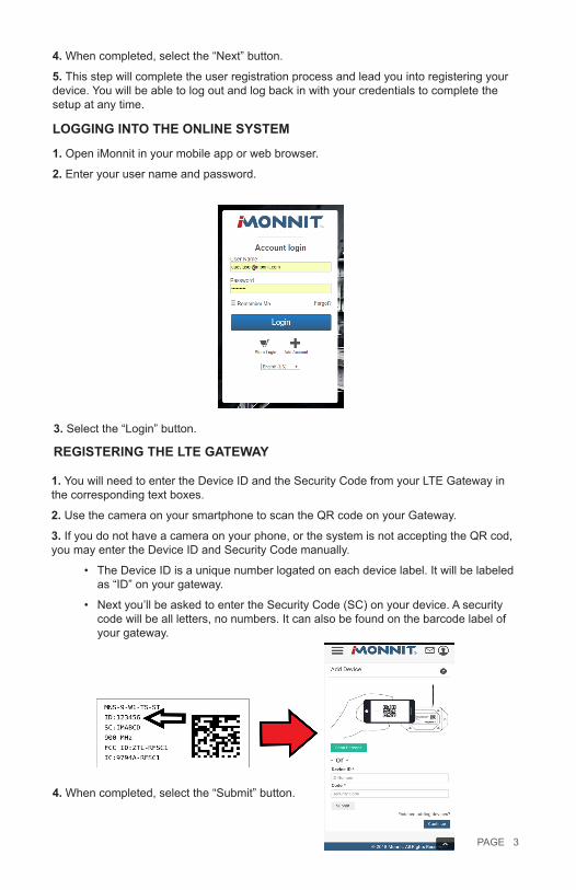
1. Open iMonnit in your mobile app or web browser.
2. Enter your user name and password.
3. Select the “Login” button.
REGISTERING THE LTE GATEWAY
1. You will need to enter the Device ID and the Security Code from your LTE Gateway in the corresponding text boxes.
2. Use the camera on your smartphone to scan the QR code on your Gateway.
3. If you do not have a camera on your phone, or the system is not accepting the QR cod, you may enter the Device ID and Security Code manually.
• The Device ID is a unique number logated on each device label. It will be labeled as “ID” on your gateway.
• Next you’ll be asked to enter the Security Code (SC) on your device. A security code will be all letters, no numbers. It can also be found on the barcode label of your gateway.
4. When completed, select the “Submit” button.
PAGE 3
II. PROGRAMMING MONNIT WI-FI SENSORS WITH NETWORK SECURITY
Visit www.mowisensors.com to download the Monnit Wi-Fi sensor setup applica-tion. This application allows you to program your Monnit Wi-Fi sensors for accessing secured Wi-Fi networks. 1. Install and Launch the MoWi Sensor setup application.
2. Click on “Download Driver” and follow the on-screen instructions to download and install the USB programming cable driver.
3. Connecting Your Wi-Fi Sensor for Programming• Insert two AA batteries into the MoWi sensor. Note: The LED will flash until the
sensor has been configured to connect with a Wi-Fi network.
• Insert the USB side of the programming cable into an available port on your PC.
• Peel back the Wi-Fi sensor’s label (where indicated) to access the programming port and insert the other end of the cable.
• When plugged in, the software image will change, confirming the sensor connec-tion. Note: The sensor LED will flash when connected to the PC.
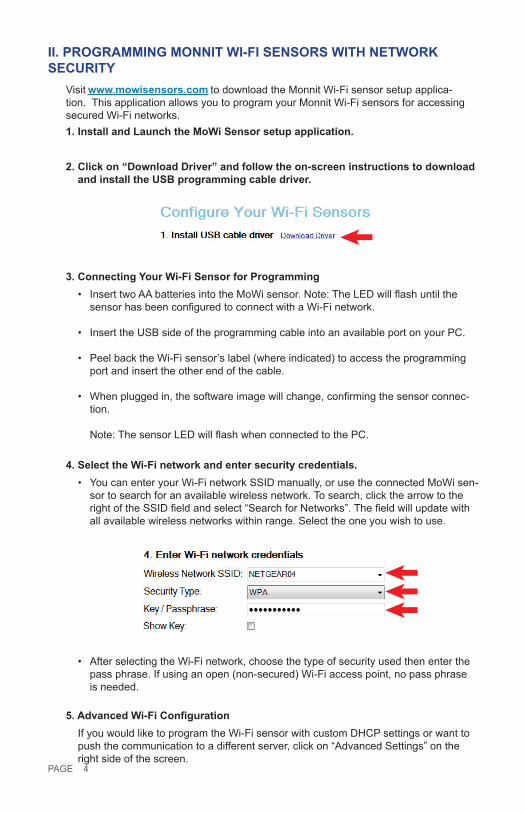
4. Select the Wi-Fi network and enter security credentials.• You can enter your Wi-Fi network SSID manually, or use the connected MoWi sen-
sor to search for an available wireless network. To search, click the arrow to the right of the SSID field and select “Search for Networks”. The field will update with all available wireless networks within range. Select the one you wish to use.
• After selecting the Wi-Fi network, choose the type of security used then enter the pass phrase. If using an open (non-secured) Wi-Fi access point, no pass phrase is needed.
5. Advanced Wi-Fi ConfigurationIf you would like to program the Wi-Fi sensor with custom DHCP settings or want to push the communication to a different server, click on “Advanced Settings” on the right side of the screen.
PAGE 4

6. Configure The Sensor• When all information has been entered, click the “Configure Sensor” button. The
configuration information will be programmed on to the sensor. When the process is complete, you will see a successful operation pop-up. Click “OK” to close it.
• It is now safe to unplug the USB cable from the Wi-Fi sensor. Repeat this process for any more sensors that need to be configured for use with your Wi-Fi network. You will not have to enter the Wi-Fi settings again unless you choose to add sen-sors to a different Wi-Fi network or you close the software application.
7. Understanding the Wi-Fi sensor LEDWhen first powered on, the LED will flash green while looking for an authorized Wi-Fi network, then go off when connected. If the LED flashes red one of the following issues is ocurring;
• 1 Red Flash: Wi-Fi security credentials are denied. (Use the MoWi PC application to re-enter the correct Wi-Fi security credentials.)
• 2 Red Flashes: Wi-Fi connected but failed to resolve network settings (DHCP/DNS). (Check the DHCP is enabled on your Wi-Fi router or assign a static IP to your sensor using the MoWi PC application.)
• 3 Red Flashes: Wi-Fi connected, network resolved, but unable to access internet. (Check that your Wi-Fi router has an active internet connection.)
Note: By default the lights will only flash upon power-up or sensor programming to let you know if there are any issues. If you would like the LED to flash during normal operation (to signify radio communication), this setting can be enabled in your sensor configurations through iMonnit. Turning on this feature can impact battery life.
8. You are now ready to log into the iMonnit online sensor portal to view sensor data and configure additional sensor settings.
III. USING THE IMONNIT ONLINE WIRELESS SENSOR SYSTEMUNDERSTANDING THE ONLINE INTERFACE
When you log into the online system, the default view shows all of your sensors last recorded data.
PAGE 5

Menu System
Details - Displays a graph of recent sensor data.
History - List of all past hearbeats and readings.
Events - List of all events attached to this sensor.
Settings - Editable levels for your sensor.
Calibrate - Reset readings for select sensors (Not available for all sensor types). Scale - Change the scale of readings for your sensor (Not available for all sensor types).
Sensor Overview
Directly under the tab bar is an overview of your sensor. This allows you to see the signal strength and the battery level of the selected sensor.
• inticates the sensor is checking in and within user defined safe parameters.
• indicates the sensor has met or exceeded a user defined threshold or triggered event.
• indicates that no sensor readings are being recorded, rendering the sensor inactive.
Note: The data shown on the chart, event, history, and export file is based on the date range indicated on the upper right side of the sensor detail information. To change the date range, click the inside of the date box.
HISTORY VIEW
Clicking on the “History” tab within the tab bar allows you to view the sensor’s data history as time stamped data.
PAGE 6

CONFIGURING SENSOR SETTINGSTo edit the operational settings for a sensor, choose the “Sensor” option in the main naviga-tion menu then select the “Settings” tab to access the configuration page.
The sensor edit panel allows you to set the primary configurations for the sensor. When you have finished making changed, press the “Save” button at the bottom of this section.
Note: Be sure to select the “Save” button anytime you make a change to any of the sensor parameters. All changes made to the sensor settings will be downloaded to the sensor on the next sensor heartbeat (check-in). Once a change has been made and saved, you will not be able to edit that sensor’s configuration again until it has down-loaded the new setting.
PAGE 7

SENSOR AND/OR GATEWAY NOTIFICATION(S)Notifications for a single sensor or gateway can be created, deleted, and edited by clicking the “Events” tab in the senor tab bar.
You can toggle the Event Trigger on or off by selecting the switch under Current Event Triggers.Creating an Event
Events are triggers or alarms set to let you know when a sensor reading identifies that im-mediate attention is needed. Types of events include sensor readings, battery level, device inactivity, and scheduled data. Any one of these can be set to send a notification or trigger an action in the system. This guide will walk you through creating two types of events. First a sensor reading notificationn for a temperature sensor, then an inactivity notifation config-ured for all sensors.1. Select Events in the main navigation menu.
2. A list of previously created events will display on the screen. From here, you have the ability to filter, refresh, and add new events to the list.
Note: If this is your first time adding an event, the screen will be blank.PAGE 8

3. From the Events page, tap “Add Event” in the left hand corner.
4. The dropdown menu will have the following options for Event Types:
• Sensor Reading: Set alerts based on sensor activity or reading.
• Battery Level: This is where you can set to be notified whend the battery level drops below a certain percent-age. 15% is the default setting.
• Device Inactivity: Alerts when the device doesn’t communicate for an extended period of time.
• Advanced: Alerts based on ad-vanced rules, such as comparing past data points with current ones.
• Scheduled: These are notifications that fire at a time set basis.
5. Select Sensor Reading from the dropdown menu.
6. A second dropdown menu will appear. From here, you will be able to see a list of the different type of sensors registered to your account. Choose Temperature in the dropdown menu.
7. Next, you will be asked to input the trigger settings. You have the option of setting this trigger for greater than or less than a temperature reading
8. Press the “Save” button.
If you don’t have a temperature sensor, the option in this example won’t be available, select any variable output sensor and follow along.
Variable output sensors can have multiple event triggers created.
Example: A temperature sensor used in a freezer. You may want to be notified if the temperature goes below 0° or above 30° Fahrenheit. You would create two events.
• Event 1- Trigger Set for temperatures LESS THAN 0°F.
• Event 2 - Trigger set for temperatures GREATER THAN 30° F.
PAGE 9

9. The Event Information page has a series of tabs across the top.
A. History: A table of all past alert notifications for this specific event.
B. Schedule: Here you can schedule the event only to be active at certain times or certain days.
C. Trigger: This is where you can review your trigger settings.
D. Actions: Where you set the action you want to happen when an alert state is triggered.
10. Choose the Trigger tab.
11. The Trigger Sensors section sits below “Trigger Conditions.” If you have multiple sensors for the same type (Example: five temperature sensors), this is where they will be listed. There should be at least one sensor in this section.
12. By default, the sensor(s) will not be assigned to the event conditions you’ve just set. To assign a sensor, find the device(s) you want to designate for this event and select. Selected sensor boxes will turn green when activated. Choose the sensor box again to unassign the sensor from the event.
13. Continue toggling the sensor(s) corresponding to this new event until you are satisfied with your selection. These can be adjusted later by returning to this page.
14. Press the “Save” button.15. Select the Actions tab.
16. Press the Add Action button under the Event Information header and available action types are presented in a select list.
• Notification Action: Specify account users to recieve notications when this event triggers.
• System Action: Assign actions for the system to process when this event triggers.17. Choose Notification Action from the notification list.
PAGE 10

A. Configure the subject for the notification.
B. Customize the message body for the notification
C. Save button commits any changes to message content fields.
D. Recipient list identifies who will recieve the notification.
• Select the icon next to a user to configure how they will be notified
• Choose if you want notifications sent immediately when triggered or if you want a delay before it is sent and press Set.
• A green icon indicates the users that will not recieve the notifications.
• If a delay has been selected, the delay time will display beside the icon.
18. Select System Action from the select list under the Event Information header.
19. Scroll down to the System Action section.
20. The Action to be Done select list has the following options.
• Acknowledge: Automatically signal that you have been notified of an event and take action. When an event has been triggered, actions will continue processing until the event returns to a value that no longer triggers an event.
• Full Reset: Reset your trigger so it is armed for the next reading.
• Activate: Enable an event trigger.
• Deactivate: Disable an event trigger.
EXPORTING SENSOR DATASensor data can be exported to a (.csv) file by following the next steps:
1. Select Sensors from the main navigation menu.
PAGE 11

2. Choose the sensor you need an export for in the list.
3. Pick the History tab.
4. On the far right of the sensor history data is a cloud icon. Selecting this icon will export an excel file for your sensor into your download folder.
Note: Make sure you have the date range for the data you need input in the “From” and “To” text boxes. This will be the most recent week by default. Only the first 2,500 entries in the selected date range will be exported.
The data file will have the following fields:
MessageID: Unique identifier of the message in our database.
SensorID: If multiple sensors are exported you can distinguish which reading was from which using this number even if the names for some reason are the same.
Sensor Name: The name you have given the sensor.
Date: The date the message was transmitted from the sensor.
Value: Data presented with transformations applied but without additional labels.
Formatted Value: Data transformed and presented as it is shown in the monitoring portal.
Battery: Estimated life remaining of the battery.
Raw Data: Raw data as it is stored from the sensor.
Sensor State: Binary field represented as an integer containing information about the state or the sensor when the message was transmitted. (See “Sensor State Explained” below).
Gateway ID: The Identifier of the gateway that relayed the data from the sensor.
Alert Sent: Boolean indicating if this reading triggered a notification to be sent from the system.
Signal Strength: Strength of communication signal between the sensor and the gateway, shown as percentage value.
Voltage: Actual voltage measured at the sensor battery used to calculate battery percent-age, similar to Received Signal you can use one or the other or both if they help you.
StateThe integer presented here is generated from a single byte of stored data. A byte consists of 8 bits of data that we read as Boolean (True (1)/False (0)) fields.
PAGE 12
Using a temperature sensor as an example.
If the sensor is using factory calibrations the Calibrate Active field is set True (1) so the bit values are 00010000 and it is represented as 16.
If the sensor is outside the Min or Max threshold, the Aware State is set True (1) so the bit values are 00000010 and it is represented as 2.
If the customer has calibrated the sensor this field the Calibrate Active field is set False (0) AND the sensor is operating inside the Min and Max Thresholds, the bits look like 00000000 this is represented as 0.
If the sensor is using factory calibrations and it is outside the threshold the bit values are 00010010 and it is represented as 18 (16 + 2 because both the bit in the 16 value is set and the bit in the 2 value is set).
Note: These two are the only bits that typically observed outside of our testing procedures.
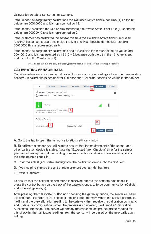
CALIBRATING SENSOR DATACertain wireless sensors can be calibrated for more accurate readings (Example: temperature sensors). If calibration is possible for a sensor, the “Calibrate” tab will be visible in the tab bar.
A. Go to the tab to open the sensor calibration settings window.
B. To calibrate a sensor, you will want to ensure that the environment of the sensor and other calibration device is stable. Note the “Expected Next Check-in” time for the sensor you are calibrating and take a reading from your calibration device a few minutes prior to the sensors next check-in.
C. Enter the actual (accurate) reading from the calibration device into the text field.
D. If you need to change the unit of measurement you can do that here.
E. Press “Calibrate”.
To ensure that the calibration command is received prior to the sensors next check-in, press the control button on the back of the gateway, once, to force communication (Cellular and Ethernet gateways).
After pressing the "Calibrate" button and choosing the gateway button, the server will send the command to calibrate the specified sensor to the gateway. When the sensor checks-in, it will send the pre-calibration reading to the gateway, then receive the calibration command and update it’s configuration. When the process is completed, it will send a “Calibration Successful” message. The server will display the sensor’s last pre-calibrated reading for this check-in, then all future readings from the sensor will be based on the new calibration setting.
PAGE 13

It is important to note that after calibrating the sensor, the sensor reading returned to the server is based on pre-calibration settings. The new calibration settings will take affect on the next sensor heartbeat.
Note: If you would like to send the changes to the sensor right away, please remove the battery(s) for a full 60 seconds, then re-insert the battery(s). This forces the communication from the sensor to the gateway and this the message to make a change from the gateway back to the sensor. (If the sensors are industrial sensors, turn the sensor off for a full minute, rather than removing the battery).
MANAGE SENSOR NETWORKSTo view or edit information about your wireless sensor network(s), select the Networks box in the account overview page.
The following network list page allows you to edit details, create new sensor tetworks, and manage wireless gateways and sensors for your network(s). Find the network you wish to modify in the list and select it to be taken to to the network edit page.
The network edit page will give the option of changing the name of your network, enable notifications, enable holding, and review the Install Tech Access Cut-off Date.Remember, you must press the “Save” button after making any changes in this section.
Below this section is a list of sensors and gateways attached to the account. Choosing the icon of a trashcan beside each sensor will delete it from the network. Selecting the
icon directly above the sensor section will allow new devices to be added to the nework. Review the steps on registering a new device on page 3 of this user guide.
PAGE 14

Additional Information and Support
You can find additional information on using Monnit Wireless Sensors, including product documentation and video tutorials on the Monnit website at http://www.monnit.com/support.
Information to Users
The Monnit wireless products referenced in this Quick Start Guide have been tested and found to comply with the standards for FCC, IC and CE certifications. For certification information on individual products please view product data sheets or product specifications on the Monnit website.
WARNING: Changes or modifications not expressly approved by Monnit could void the user’s authority to operate the equipment.
IndustryCanada
For additional information or more detailed instructions on how to use your Monnit Wireless Sensors or the iMonnit Online System, please visit us on the web at http://www.monnit.com/support/.
Monnit Corporation4403 South 500 WestMurray, UT 84123801-561-5555www.monnit.com
M-QS05-2C (09/15)Monnit, Monnit Logo and all other trademarks are property of Monnit, Corp.
© 2009-2018 Monnit Corp. All Rights Reserved.