monitoring relays - eatonelectrical.capub/@eatonca/@elec/...voltage monitoring relays . . . . . . ....
TRANSCRIPT

V5-T5-2 Volume 5—Power Control Products CA033001EN—January 2017 www.eatoncanada.ca
5
5
5
5
5
5
5
5
5
5
5
5
5
5
5
5
5
5
5
5
5
5
5
5
5
5
5
5
5
5
5.1 Motor Protection and Monitoring
Monitoring Relays
Monitoring Relays ContentsDescription Page
Monitoring RelaysCurrent Monitoring Relays . . . . . . . . . . . . . . . . V5-T5-3
Phase Monitoring Relays . . . . . . . . . . . . . . . . . V5-T5-14
Voltage Monitoring Relays . . . . . . . . . . . . . . . . V5-T5-26
Ground Fault Monitoring Relays . . . . . . . . . . . . V5-T5-40
Product Overview—Monitoring RelaysCurrent Monitoring RelaysThe D65C Series Current Monitoring Relays monitor AC single-phase currents for over- or undercurrent conditions in three current ranges: 0.1–1A, 0.5–5A and 1–10A. An external current transformer may be used to extend the range of the product. A separate 24V or 120 Vac input (supply) voltage is required to power the unit. All versions are available in a compact plug-in case using industry standard 8- or 11-pin octal sockets
Phase Monitoring RelaysThe D65 Series Phase Monitoring Relays provide protection against premature equipment failure caused by voltage faults on three-phase systems. All D65 phase monitoring relays are compatible with most wye or delta systems. In wye systems, a connection to neutral is not required. Phase Monitoring relays protect against single-phasing regardless of any regenerative voltages.
Voltage Monitoring RelaysThe D65 Series Voltage Monitoring Relays monitor either AC single-phase (50/60 Hz) or DC voltages to protect equipment against voltage fault conditions. No separate supply (input) voltage is required. All versions are available in a compact plug-in case using an 8-pin octal socket.
There are two styles of voltage monitoring relays:
● Over/Undervoltage Relays● Voltage Band Relays
Ground Fault Monitoring RelaysEaton offers two different series of ground fault monitoring relays:
D64R Series● The new D64R digital
ground fault relays are microprocessor-based and replace the previous generation of analogue-based devices
● Microprocessor-based D64R GFRs combine more selectable features into a single model, which makes easier model selection and reduces spares inventory requirements
D64L Series● Type D64L ground fault
monitors are designed to monitor ungrounded supplies on three-phase AC power systems up to 600V. If an insulation fault develops anywhere on the system between the source and the load, the D64L will detect it and give an alarm or trip, depending on the adjustable field settings selected
● The D64L is ideally suited for systems supplied from the secondary of either an ungrounded delta or an ungrounded wye connected transformer

Volume 5—Power Control Products CA033001EN—January 2017 www.eatoncanada.ca V5-T5-3
5
5
5
5
5
5
5
5
5
5
5
5
5
5
5
5
5
5
5
5
5
5
5
5
5
5
5
5
5
5
5.1Motor Protection and Monitoring
Monitoring Relays
Current Monitoring Relays ContentsDescription Page
Current Monitoring RelaysD65 Current Monitoring Relays
Product Selection Guide . . . . . . . . . . . . . . . V5-T5-4
D65CE Series—Standard Current Monitors . . . . . . . . . . . . . . . . . . . . . . . . . . V5-T5-5
D65CH Series—Overcurrent Monitors . . . . V5-T5-8
D65CL Series—Undercurrent Monitors . . . V5-T5-11
Phase Monitoring Relays . . . . . . . . . . . . . . . . . . . . V5-T5-14
Voltage Monitoring Relays . . . . . . . . . . . . . . . . . . . V5-T5-26
Ground Fault Monitoring Relays . . . . . . . . . . . . . . V5-T5-40
Product Overview
The D65C Series Current Monitoring Relays monitor AC single-phase currents for over- or undercurrent conditions in three current ranges: 0.1–1A, 0.5–5A and 1–10A. An external current transformer may be used to extend the
range of the product. A separate 24V or 120 Vac input (supply) voltage is required to power the unit. All versions are available in a compact plug-in case using industry standard 8- or 11-pin octal sockets.
Application Description
Typical Installation without External CT
Typical Installation with External CT
Current Monitor Relay
ControlVoltage
M
MotorM
ML1
L2
65
3 4 12
8
Current Monitor Relay
ControlVoltage
M
ML1
L2
M
Motor
65
3 4 12
8
Standards and Certifications● CE● cRUus listed● UL listed 12
● RoHS compliant
Notes1 When used with accompanying Eaton
socket.2 In addition to the above approvals, all
plug-in products are also UL Listed when used with the appropriate Eaton socket.

V5-T5-4 Volume 5—Power Control Products CA033001EN—January 2017 www.eatoncanada.ca
5
5
5
5
5
5
5
5
5
5
5
5
5
5
5
5
5
5
5
5
5
5
5
5
5
5
5
5
5
5
5.1 Motor Protection and Monitoring
Monitoring Relays
Product Selection GuideStandardFixed time delay on both pickup and dropout current settings.
D65C Standard Function
OvercurrentAdjustable time delay on pickup and fixed time delay on dropout current settings.
D65C Overcurrent Function
UndercurrentFixed time delay on pickup and adjustable time delay on dropout current settings.
D65C Undercurrent Function
Note1 Fixed time delay eliminates nuisance tripping due to short current surges or drops.
SeriesPickup Dropout
PageSetting Time Delay Setting Time Delay
D65CE Adjustable (across monitored range)
Fixed 100 ms 1 Fixed (–5% pickup) Fixed 100 ms 1 V5-T5-6
D65CEK Adjustable (50–95% pickup)
SeriesPickup Dropout
PageSetting Time Delay Setting Time Delay
D65CH Adjustable (across monitored range)
0.1–10 sec adjustable Fixed (–5% pickup) Fixed 100 ms 1 V5-T5-9
D65CHK Adjustable (50–95% pickup)
SeriesPickup Dropout
PageSetting Time Delay Setting Time Delay
D65CL Fixed (+5% dropout)
Fixed 100 ms 1 Adjustable (across monitored range)
0.1–10 sec adjustable V5-T5-12

Volume 5—Power Control Products CA033001EN—January 2017 www.eatoncanada.ca V5-T5-5
5
5
5
5
5
5
5
5
5
5
5
5
5
5
5
5
5
5
5
5
5
5
5
5
5
5
5
5
5
5
5.1Motor Protection and Monitoring
Monitoring Relays
D65CE Series—Standard Current Monitors ContentsDescription Page
Current Monitoring RelaysD65 Current Monitoring Relays
Product Selection Guide . . . . . . . . . . . . . . . V5-T5-4
D65CE Series—Standard Current MonitorsProduct Selection . . . . . . . . . . . . . . . . . . V5-T5-6
Technical Data and Specifications . . . . . V5-T5-7
Dimensions . . . . . . . . . . . . . . . . . . . . . . V5-T5-7
D65CH Series—Overcurrent Monitors . . . . V5-T5-8
D65CL Series—Undercurrent Monitors . . . V5-T5-11
Phase Monitoring Relays . . . . . . . . . . . . . . . . . . . . V5-T5-14
Voltage Monitoring Relays . . . . . . . . . . . . . . . . . . . V5-T5-26
Ground Fault Monitoring Relays . . . . . . . . . . . . . . V5-T5-40
D65CE Series—Standard Current Monitors Product DescriptionThe D65CE Series Standard Current Monitors are used to detect either an overcurrent or undercurrent condition. The pickup current setting is user-adjustable within three ranges (0.1–1A), (0.5–5A), or (1–10A). The range can be extended beyond 10A with the use of an external current transformer. Choose between a fixed dropout current setting at 95% of the selected pickup setting or an adjustable dropout setting of 50–95% of the selected pickup setting. The relay will energize when the monitored AC current is above the pickup setting, and will de-energize when the monitored AC current is below the dropout setting. The time delay on both pickup and dropout is fixed at 100 ms. Adjustable time delays are available with the D65CH and D65CL Series.
Features● Monitors AC single-phase
currents● Three separate current
monitoring ranges covering 0.1–10 amperes
● External CT can be used to extend ranges
● Adjustable pickup setting with either fixed or adjustable dropout setting
● LED indicates output relay status
● Choice of compact 8-pin SPDT or 11-pin DPDT plug-in case
● 10A output contacts
Standard Current Monitoring
MonitoredCurrent
PickupCurrent
DropoutCurrent
InputPower
(Voltage)
RelayOutput
On
On
Off
Off

V5-T5-6 Volume 5—Power Control Products CA033001EN—January 2017 www.eatoncanada.ca
5
5
5
5
5
5
5
5
5
5
5
5
5
5
5
5
5
5
5
5
5
5
5
5
5
5
5
5
5
5
5.1 Motor Protection and Monitoring
Monitoring Relays
Product Selection
D65CE Series—Standard Current Monitors, SPDT, 8-Pin Plug-In
D65CE Series—Standard Current Monitors, SPDT, 11-Pin Plug-In
Accessories
D65CE Current Monitors
Pickup Setting
Dropout Setting Input Voltage
Current Range Monitored
CatalogueNumber
Adjustable Fixed (at 95% of pickup)
24 Vac 0.1–1A D65CE1C01T
0.5–5A D65CE1C5T
1–10A D65CE1C10T
120 Vac 0.1–1A D65CE1C01A
0.5–5A D65CE1C5A
1–10A D65CE1C10A
Adjustable(from 50–95% of pickup)
24 Vac 0.1–1A D65CEK1C01T
0.5–5A D65CEK1C5T
1–10A D65CEK1C10T
120 Vac 0.1–1A D65CEK1C01A
0.5–5A D65CEK1C5A
1–10A D65CEK1C10A
Pickup Setting
Dropout Setting Input Voltage
Current Range Monitored
CatalogueNumber
Adjustable Fixed (at 95% of pickup)
24 Vac 0.1–1A D65CE2C01T
0.5–5A D65CE2C5T
1–10A D65CE2C10T
120 Vac 0.1–1A D65CE2C01A
0.5–5A D65CE2C5A
1–10A D65CE2C10A
Adjustable(from 50–95% of pickup)
24 Vac 0.1–1A D65CEK2C01T
0.5–5A D65CEK2C5T
1–10A D65CEK2C10T
120 Vac 0.1–1A D65CEK2C01A
0.5–5A D65CEK2C5A
1–10A D65CEK2C10A
DescriptionStandard Pack
CatalogueNumber
8-pin socket 10 D3PA2
11-pin socket 10 D3PA3-A2
Hold-down spring 10 D65CHDS
D65CE_
D65CE_

Volume 5—Power Control Products CA033001EN—January 2017 www.eatoncanada.ca V5-T5-7
5
5
5
5
5
5
5
5
5
5
5
5
5
5
5
5
5
5
5
5
5
5
5
5
5
5
5
5
5
5
5.1Motor Protection and Monitoring
Monitoring Relays
Technical Data and Specifications
D65CE Series, Standard Current Monitors
DimensionsApproximate Dimensions in Inches (mm)
D65CE Series, Standard Current Monitors
D3PA2 Sockets D3PA3 Sockets
Description Specification
Input voltage tolerance AC operation: +10/–15% of nominal voltage at 50/60 Hz
Load (burden) Less than 5 VA
Current settings Pickup Adjustable throughout current range monitored
Dropout Fixed at 95% of pickup setting for D65CEAdjustable from 50–95% of pickup setting for D65CEK
Temperature –20° to 131°F (–28° to 55°C)
Response times Pickup 100 ms
Dropout 100 ms
Output contacts 10A resistive at 240 Vac/30 Vdc1/2 hp at 240 Vac (NO); 1/3 hp at 240 Vac (NC)
Mechanical life 10,000,000 operations
Electrical life 100,000 operations
Indicator LED Green when input voltage is applied; red when relay is energized
Reset Automatic
Mounting Requires an 8- or 11-pin socket
Wiring DiagramsWiring for 8-Pin Socket
Wiring for 11-Pin Socket
1
4
(L1)
MonitoredCurrent
InputVoltage
(L2)
3 6
2 78
5
1
(L1) (L2)
11
MonitoredCurrent
4 8
3 9
6
2 10
75
2.4(60)
1.7(43)
2.9(74)
3.5(89)
D65CEKOnly
0.97(24.6)Max.
0.82 (20.8)
0.58 (14.7)
2.03(51.6)
Two 0.165(4.2) Dia.
Slots2.14
(54.3)
1.60(40.6)Max.
1.30(33.0)
6–32 x 0.312 CombinationHead Screw and Pressure Clamping Plate
(8 places)
Tolerances: ± 0.010 ± (0.25)
Unless Otherwise Shown
6–32 x 0.312 CombinationHead Screw and Pressure Clamp
(11 places)
2.05(52.1)Max.
2.33 (59.2)Max.
2.06(52.3)
0.97(24.6)
0.77 (19.6)0.58 (14.7)0.15 (3.8)
0.13–0.16 (3.2–4.0)
Two 0.17(4.3) Dia.
Holes
Tolerances: ± 0.010 ± (0.25)
Unless Otherwise Shown

V5-T5-8 Volume 5—Power Control Products CA033001EN—January 2017 www.eatoncanada.ca
5
5
5
5
5
5
5
5
5
5
5
5
5
5
5
5
5
5
5
5
5
5
5
5
5
5
5
5
5
5
5.1 Motor Protection and Monitoring
Monitoring Relays
D65CH Series—Overcurrent Monitors ContentsDescription Page
Current Monitoring RelaysD65 Current Monitoring Relays
Product Selection Guide . . . . . . . . . . . . . . . V5-T5-4
D65CE Series—Standard Current Monitors . . . . . . . . . . . . . . . . . . . . . . . . . . V5-T5-5
D65CH Series—Overcurrent MonitorsProduct Selection . . . . . . . . . . . . . . . . . . V5-T5-9
Technical Data and Specifications . . . . . V5-T5-10
Dimensions . . . . . . . . . . . . . . . . . . . . . . V5-T5-10
D65CL Series—Undercurrent Monitors . . . V5-T5-11
Phase Monitoring Relays . . . . . . . . . . . . . . . . . . . V5-T5-14
Voltage Monitoring Relays . . . . . . . . . . . . . . . . . . V5-T5-26
Ground Fault Monitoring Relays . . . . . . . . . . . . . . V5-T5-40
D65CH Series—Overcurrent MonitorsProduct DescriptionThe D65CH Series Overcurrent Monitoring Relays are used to detect an overcurrent condition. The pickup current setting is user-adjustable within one of three ranges as shown in product selection table. An external current transformer can be used to extend the range beyond 10A. Users may select a fixed dropout current setting (95% of the selected pick-up setting) or an adjustable drop-out setting (50–95% of the selected pickup setting). The relay will energize when the monitored AC current is above the pickup setting for a period longer than the adjustable time delay of 0.1–10 seconds. This delay prevents nuisance tripping caused by inrush currents. It will de-energize when the monitored AC current is below the dropout setting.
Features● Monitors AC single-phase
currents for overcurrent conditions
● Three separate current monitoring ranges covering 0.1–10 amperes
● External CT can be used to extend ranges
● Adjustable pickup setting with either fixed or adjustable dropout setting
● Adjustable time delay of 0.1–10 seconds on pickup
● LED indicates output relay status
● Choice of compact SPDT (8-pin) or DPDT (11-pin) plug-in case
● 10A output contacts
Overcurrent Monitoring
MonitoredCurrent
PickupCurrent
DropoutCurrent
InputPower
(Voltage)
RelayOutput
On
On
T T
Off
Off

Volume 5—Power Control Products CA033001EN—January 2017 www.eatoncanada.ca V5-T5-9
5
5
5
5
5
5
5
5
5
5
5
5
5
5
5
5
5
5
5
5
5
5
5
5
5
5
5
5
5
5
5.1Motor Protection and Monitoring
Monitoring Relays
Product Selection
D65CH Series—Overcurrent Monitors, SPDT, 8-Pin Plug-In
D65CH Series—Overcurrent Monitors, SPDT, 11-Pin Plug-In
Accessories
D65CH Overcurrent Monitors
Pick-Up Setting
Drop-Out Setting Input Voltage
Current Range Monitored
CatalogueNumber
Adjustable Fixed (at 95% of pickup)
24 Vac 0.1–1A D65CH1C1T
0.5–5A D65CH1C5T
1–10A D65CH1C10T
120 Vac 0.1–1A D65CH1C1A
0.5–5A D65CH1C5A
1–10A D65CH1C10A
Adjustable(from 50–95% of pickup)
24 Vac 0.1–1A D65CHK1C1T
0.5–5A D65CHK1C5T
1–10A D65CHK1C10T
120 Vac 0.1–1A D65CHK1C1A
0.5–5A D65CHK1C5A
1–10A D65CHK1C10A
Pick-Up Setting
Drop-Out Setting Input Voltage
Current Range Monitored
CatalogueNumber
Adjustable Fixed (at 95% of pickup)
24 Vac 0.1–1A D65CH2C1T
0.5–5A D65CH2C5T
1–10A D65CH2C10T
120 Vac 0.1–1A D65CH2C1A
0.5–5A D65CH2C5A
1–10A D65CH2C10A
Adjustable(from 50–95% of pickup)
24 Vac 0.1–1A D65CHK2C1T
0.5–5A D65CHK2C5T
1–10A D65CHK2C10T
120 Vac 0.1–1A D65CHK2C1A
0.5–5A D65CHK2C5A
1–10A D65CHK2C10A
DescriptionStandard Pack
CatalogueNumber
8-pin socket 10 D3PA2
11-pin socket 10 D3PA3-A2
Hold-down spring 10 D65CHDS
D65CH_
D65CH_

V5-T5-10 Volume 5—Power Control Products CA033001EN—January 2017 www.eatoncanada.ca
5
5
5
5
5
5
5
5
5
5
5
5
5
5
5
5
5
5
5
5
5
5
5
5
5
5
5
5
5
5
5.1 Motor Protection and Monitoring
Monitoring Relays
Technical Data and Specifications
D65CH Series, Overcurrent Monitors
DimensionsApproximate Dimensions in Inches (mm)
D65CH Series, Overcurrent Monitors
D3PA2 Sockets D3PA3 Sockets
Description Specification
Input voltage tolerance AC operation: +10/–15% of nominal voltage at 50/60 Hz
Load (burden) Less than 5 VA
Current settings Pickup Adjustable throughout current range monitored
Dropout Fixed at 95% of pickup setting for D65CEAdjustable from 50–95% of pickup setting for D65CEK
Temperature –20° to 131°F (–28° to 55°C)
Response times Pickup Adjustable 0.1–10 seconds
Dropout Fixed at 100 ms
Output contacts 10A resistive at 240 Vac/30 Vdc1/2 hp at 240 Vac (NO); 1/3 hp at 240 Vac (NC)
Mechanical life 10,000,000 operations
Electrical life 100,000 operations
Indicator LED Green when input voltage is applied; red flashing when in time delay; red steady when relay is energized
Reset Automatic
Mounting Requires an 8- or 11-pin socket
Wiring DiagramsWiring for 8-Pin Socket
Wiring for 11-Pin Socket
1
4
(L1)
MonitoredCurrent
InputVoltage
(L2)
3 6
2 78
5
1
(L1) (L2)
11
MonitoredCurrent
4 8
3 9
6
2 10
75
2.4(60)
1.7(43)
2.9(74)
3.5(89)
D65CHKOnly
0.97(24.6)Max.
0.82 (20.8)
0.58 (14.7)
2.03(51.6)
Two 0.165(4.2) Dia.
Slots2.14
(54.3)
1.60(40.6)Max.
1.30(33.0)
6–32 x 0.312 CombinationHead Screw and Pressure Clamping Plate
(8 places)
Tolerances: ± 0.010 ± (0.25)
Unless Otherwise Shown
6–32 x 0.312 CombinationHead Screw and Pressure Clamp
(11 places)
2.05(52.1)Max.
2.33 (59.2)Max.
2.06(52.3)
0.97(24.6)
0.77 (19.6)0.58 (14.7)0.15 (3.8)
0.13–0.16 (3.2–4.0)
Two 0.17(4.3) Dia.
Holes
Tolerances: ± 0.010 ± (0.25)
Unless Otherwise Shown

Volume 5—Power Control Products CA033001EN—January 2017 www.eatoncanada.ca V5-T5-11
5
5
5
5
5
5
5
5
5
5
5
5
5
5
5
5
5
5
5
5
5
5
5
5
5
5
5
5
5
5
5.1Motor Protection and Monitoring
Monitoring Relays
D65CL Series—Undercurrent Monitors ContentsDescription Page
Current Monitoring RelaysD65 Current Monitoring Relays
Product Selection Guide . . . . . . . . . . . . . . . V5-T5-4
D65CE Series—Standard Current Monitors . . . . . . . . . . . . . . . . . . . . . . . . . . V5-T5-5
D65CH Series—Overcurrent Monitors . . . . V5-T5-8
D65CL Series—Undercurrent MonitorsProduct Selection . . . . . . . . . . . . . . . . . . V5-T5-12
Technical Data and Specifications . . . . . V5-T5-13
Dimensions . . . . . . . . . . . . . . . . . . . . . . V5-T5-13
Phase Monitoring Relays . . . . . . . . . . . . . . . . . . . . V5-T5-14
Voltage Monitoring Relays . . . . . . . . . . . . . . . . . . . V5-T5-26
Ground Fault Monitoring Relays . . . . . . . . . . . . . . V5-T5-40
D65CL Series—Undercurrent MonitorsProduct DescriptionThe D65CL Series is designed to detect an undercurrent condition. The dropout current setting is user-adjustable within one of three ranges as shown in the product selection table. An external current transformer can be used to extend the range beyond 10A. The pickup current setting is fixed at +5% of the selected drop-out setting. The relay will energize when the monitored AC current is above the pickup setting. It will de-energize when the monitored AC current is below the dropout setting for a period longer than the adjustable time delay of 0.1–10 seconds. This delay prevents nuisance tripping caused by momentary line dips. The relay will energize when the current rises 5% above the dropout setting.
Features● Monitors AC single-phase
currents for undercurrent conditions
● Three separate current monitoring ranges covering 0.1–10 amperes
● External CT can be used to extend ranges
● Adjustable dropout setting with fixed pickup setting
● Adjustable time delay of 0.1–10 seconds on dropout
● LED indicates output relay status
● Choice of compact SPDT (8-pin) or DPDT (11-pin) plug-in case
● 10A output contacts
Undercurrent Monitoring
MonitoredCurrent
PickupCurrent
DropoutCurrent
InputPower
(Voltage)
RelayOutput
On
On
T
Off
Off

V5-T5-12 Volume 5—Power Control Products CA033001EN—January 2017 www.eatoncanada.ca
5
5
5
5
5
5
5
5
5
5
5
5
5
5
5
5
5
5
5
5
5
5
5
5
5
5
5
5
5
5
5.1 Motor Protection and Monitoring
Monitoring Relays
Product Selection
D65CL Series—Undercurrent Monitors, SPDT, 8-Pin Plug-In
D65CL Series—Undercurrent Monitors, SPDT, 11-Pin Plug-In
Accessories
D65CL Undercurrent Monitors
Pickup Setting
Dropout Setting Input Voltage
Current Range Monitored
CatalogueNumber
Fixed (at 5% of Dropout) Adjustable 24 Vac 0.1–1A D65CL1C1T
0.5–5A D65CL1C5T
1–10A D65CL1C10T
120 Vac 0.1–1A D65CL1C1A
0.5–5A D65CL1C5A
1–10A D65CL1C10A
Pickup Setting
Dropout Setting Input Voltage
Current Range Monitored
CatalogueNumber
Adjustable Fixed (at 95% of pickup)
24 Vac 0.1–1A D65CL2C1T
0.5–5A D65CL2C5T
1–10A D65CL210T
120 Vac 0.1–1A D65CL2C1A
0.5–5A D65CL2C5A
1–10A D65CL2C10A
DescriptionStandard Pack
CatalogueNumber
8-pin socket 10 D3PA2
11-pin socket 10 D3PA3-A2
Hold-down spring 10 D65CHDS
D65CL_
D65CL_

Volume 5—Power Control Products CA033001EN—January 2017 www.eatoncanada.ca V5-T5-13
5
5
5
5
5
5
5
5
5
5
5
5
5
5
5
5
5
5
5
5
5
5
5
5
5
5
5
5
5
5
5.1Motor Protection and Monitoring
Monitoring Relays
Technical Data and Specifications
D65CL Series, Undercurrent Monitors
DimensionsApproximate Dimensions in Inches (mm)
D65CL Series, Undercurrent Monitors
D3PA2 Sockets D3PA3 Sockets
Description Specification
Input voltage tolerance AC operation: +10/–15% of nominal voltage at 50/60 Hz
Load (burden) Less than 5 VA
Current settings Pickup Fixed at 5% above adjustable dropout setting
Dropout Adjustable throughout current range monitored
Temperature –20° to 131°F (–28° to 55°C)
Response times Pickup Fixed at 100 ms
Dropout Adjustable 0.1–10 seconds
Output contacts 10A resistive at 240 Vac/30 Vdc1/2 hp at 240 Vac (NO); 1/3 hp at 240 Vac (NC)
Mechanical life 10,000,000 operations
Electrical life 100,000 operations
Indicator LED Green when input voltage is applied; red flashing when in time delay; red steady when relay is energized
Reset Automatic
Mounting Requires an 8- or 11-pin socket
Wiring DiagramsWiring for 8-Pin Socket
Wiring for 11-Pin Socket
1
4
(L1)
MonitoredCurrent
InputVoltage
(L2)
3 6
2 78
5
1
(L1) (L2)
11
MonitoredCurrent
4 8
3 9
6
2 10
75
2.4(60)
1.7(43)
2.9(74)
3.5(89)
0.97(24.6)Max.
0.82 (20.8)
0.58 (14.7)
2.03(51.6)
Two 0.165(4.2) Dia.
Slots2.14
(54.3)
1.60(40.6)Max.
1.30(33.0)
6–32 x 0.312 CombinationHead Screw and Pressure Clamping Plate
(8 places)
Tolerances: ± 0.010 ± (0.25)
Unless Otherwise Shown
6–32 x 0.312 CombinationHead Screw and Pressure Clamp
(11 places)
2.05(52.1)Max.
2.33 (59.2)Max.
2.06(52.3)
0.97(24.6)
0.77 (19.6)0.58 (14.7)0.15 (3.8)
0.13–0.16 (3.2–4.0)
Two 0.17(4.3) Dia.
Holes
Tolerances: ± 0.010 ± (0.25)
Unless Otherwise Shown

V5-T5-14 Volume 5—Power Control Products CA033001EN—January 2017 www.eatoncanada.ca
5
5
5
5
5
5
5
5
5
5
5
5
5
5
5
5
5
5
5
5
5
5
5
5
5
5
5
5
5
5
5.1 Motor Protection and Monitoring
Monitoring Relays
Phase Monitoring Relays ContentsDescription Page
Current Monitoring Relays . . . . . . . . . . . . . . . . . . V5-T5-3
Phase Monitoring RelaysStandards and Certifications . . . . . . . . . . . . . . V5-T5-15
Product Selection Guide . . . . . . . . . . . . . . . . . V5-T5-15
D65VMC Series—Phase Reversal . . . . . . . . . . V5-T5-16
D65PLR Series—Phase Loss and Reversal . . . V5-T5-18
D65PAR Series—Phase Loss, Reversal and Undervoltage . . . . . . . . . . . . . . . . . . . . . V5-T5-20
D65VM Series—Phase Loss, Reversal, Imbalance and Under/Overvoltage . . . . . . . . V5-T5-22
Voltage Monitoring Relays . . . . . . . . . . . . . . . . . . V5-T5-26
Ground Fault Monitoring Relays . . . . . . . . . . . . . . V5-T5-40
Product OverviewThe D65 Series Phase Monitoring Relays provide protection against premature equipment failure caused by voltage faults on three-phase systems. All D65 phase monitoring relays are compatible with most wye or delta systems. In wye systems, a connection to neutral is not required. Phase Monitoring relays protect against single-phasing regardless of any regenerative voltages.
Application DescriptionProtectionDepending on the unit selected, it will protect three-phase equipment against:
● Phase Loss—total loss of one or more of the three phases. Also known as “single phasing.” Typically caused by a blown fuse, broken wire or worn contact. This condition would result in a motor drawing locked rotor current during startup. In addition, a three-phase motor will continue to run after losing a phase, resulting in possible motor burn-out.
● Phase Reversal—reversing any two of the three phases will cause a three-phase motor to run in the opposite direction. This may cause damage to driven machinery or injury to personnel. The condition usually occurs as a result of mistakes made during routine maintenance or when modifications are made to the circuit.
● Phase Imbalance—imbalance of a three-phase system occurs when single-phase loads are connected such that one or two of the lines (phases) carry more or less of the load. This could cause motors to run at temperatures above published ratings.
● Undervoltage—when voltage in all three lines of a three-phase system drop simultaneously.
● Overvoltage—when voltage in all three lines of a three-phase system increase simultaneously.

Volume 5—Power Control Products CA033001EN—January 2017 www.eatoncanada.ca V5-T5-15
5
5
5
5
5
5
5
5
5
5
5
5
5
5
5
5
5
5
5
5
5
5
5
5
5
5
5
5
5
5
5.1Motor Protection and Monitoring
Monitoring Relays
Typical Connections
Line Side MonitoringWith the relay connected before the motor starter, the motor can be started in the reverse direction. However, the motor is unprotected against phase failures between the relay and the motor.
Line Side Monitoring
Standards and Certifications
D65VMC, D65PLR and D65PAR Series● cRUus listed● RoHS recognized● CE marked (pending)
D65VMLP Series● cRUus listed● RoHS recognized● CE marked
Product Selection Guide
D65 Series—Product Family Selection
Note1 In addition to the above approvals, all plug-in products are
also UL Listed when used with the appropriate Eaton socket.
L1
StopStart
PhaseMonitor
Relay
M
3PhaseMotor
O/LL2
L1M
M
M
M
Input Fuses2A Max.
PhaseMonitor
Relay
L2
L3
(Pending)
Series Mounting Style Phase ReversalPhase Loss and Reversal Undervoltage Overvoltage Phase Imbalance
Time Delay on Undervoltage
D65VMC Plug-in 1 3 — — — — —
D65PLR Plug-in 1 3 3 — — — —
D65PAR Plug-in 1 3 3 ✓ (adjustable) — — 50 ms fixed
D65VMLP Plug-in 1 3 3 ✓ (adjustable) ✓ (fixed) 3 0.1–20 sec
D65VMLS Surface 3 3 ✓ (adjustable) ✓ (fixed) 3 0.1–20 sec
Load Side MonitoringWith the relay connected directly to the motor, the total feed lines are monitored. This connection should not be used with reversing motors.
Load Side Monitoring
D65VMLS Series● cULus listed● RoHS recognized● CE marked
L1
Stop
3PhaseMotor
O/LL2
M
M
M
M
Input Fuses2A Max.
PhaseMonitor
Relay
PhaseMonitor Relay
Start
L1
L2
L3

V5-T5-16 Volume 5—Power Control Products CA033001EN—January 2017 www.eatoncanada.ca
5
5
5
5
5
5
5
5
5
5
5
5
5
5
5
5
5
5
5
5
5
5
5
5
5
5
5
5
5
5
5.1 Motor Protection and Monitoring
Monitoring Relays
D65VMC Series—Phase Reversal ContentsDescription Page
Current Monitoring Relays . . . . . . . . . . . . . . . . . . V5-T5-3
Phase Monitoring RelaysProduct Selection Guide . . . . . . . . . . . . . . . . . V5-T5-15
D65VMC Series—Phase ReversalProduct Selection . . . . . . . . . . . . . . . . . . . . V5-T5-17
Technical Data and Specifications . . . . . . . . V5-T5-17
Dimensions . . . . . . . . . . . . . . . . . . . . . . . . . V5-T5-17
D65PLR Series—Phase Loss and Reversal . . . V5-T5-18
D65PAR Series—Phase Loss, Reversal and Undervoltage . . . . . . . . . . . . . . . . . . . . . V5-T5-20
D65VM Series—Phase Loss, Reversal, Imbalance and Under/Overvoltage . . . . . . . . V5-T5-22
Voltage Monitoring Relays . . . . . . . . . . . . . . . . . . V5-T5-26
Ground Fault Monitoring Relays . . . . . . . . . . . . . . V5-T5-40
D65VMC Series—Phase ReversalProduct DescriptionThe D65VMC Series Monitoring Relays provide protection against phase reversal in a compact plug-in design. One version will work on any three-phase system from 208V to 480V (a separate 120V-only version is also available). These devices are designed to be compatible with most wye or delta systems. In wye systems, a connection to a neutral is not required.
The relay is energized and the LED on when the sequence is correct. Any fault will de-energize the relay and turn off the LED. Re-energization is automatic upon correction of the fault condition.
Features● Protects against phase
reversal● One version works on
208–480V three-phase systems
● LED indicates both normal and fault conditions
● Compact plug-in case utilizing industry-standard 8-pin octal socket
● 10A SPDT output contacts
Standards and Certifications● cRUus● UL listed 1
● RoHS compliant
Note1 When used with appropriate Eaton
socket.

Volume 5—Power Control Products CA033001EN—January 2017 www.eatoncanada.ca V5-T5-17
5
5
5
5
5
5
5
5
5
5
5
5
5
5
5
5
5
5
5
5
5
5
5
5
5
5
5
5
5
5
5.1Motor Protection and Monitoring
Monitoring Relays
Product Selection
D65VMC Series, Phase Reversal
Accessories
D65VMC Series, Phase Reversal
Technical Data and Specifications
D65VMC Series, Phase Reversal
DimensionsApproximate Dimensions in Inches (mm)
D65VMC Series, Phase Reversal
Note1 Requires a 600V rated socket when used on system voltages greater than 300V.
MountingStyle
Nominal Voltage50/60 Hz
CatalogueNumber
Plug-in 120V D65VMC120
Plug-in 208–480V D65VMC480 1
Description Standard PackCatalogueNumber
8-pin socket 10 D3PA2
Hold-down spring 10 D65CHDS
Description Specification
Phase reversal Unit trips if sequence of the three phases is anything other than A-B-C
Output contacts 10A SPDT at 240 Vac, 1/3 hp at 240 Vac (NO), 1/6 hp at 240 Vac (NC)
Life Full load—100,000 operations
Response times
Operate 50 ms
Release 50 ms
Load (burden) 3 VA
Temperature –20° to 150°F (–28° to 65°C)
Transient protection 10,000 volts for 20 microseconds
Mounting Uses an 8-pin octal socket. Requires a 600V rated socket when used on system voltages greater than 300V
Indicator LED Red LED on when all conditions are normal, and off when a fault condition has occurred
Reset Automatic upon correction of fault
D65VMC120
Wiring DiagramWiring for 8-Pin Socket
1
4
ØA ØB ØC
3 6
2 78
5
2.40(60.0)
1.70(43.0)
2.90(74.0)
3.00(76.0)

V5-T5-18 Volume 5—Power Control Products CA033001EN—January 2017 www.eatoncanada.ca
5
5
5
5
5
5
5
5
5
5
5
5
5
5
5
5
5
5
5
5
5
5
5
5
5
5
5
5
5
5
5.1 Motor Protection and Monitoring
Monitoring Relays
D65PLR Series—Phase Loss and Reversal ContentsDescription Page
Current Monitoring Relays . . . . . . . . . . . . . . . . . . V5-T5-3
Phase Monitoring RelaysProduct Selection Guide . . . . . . . . . . . . . . . . . V5-T5-15
D65VMC Series—Phase Reversal . . . . . . . . . . V5-T5-16
D65PLR Series—Phase Loss and ReversalProduct Selection . . . . . . . . . . . . . . . . . . . . V5-T5-19
Technical Data and Specifications . . . . . . . . V5-T5-19
Dimensions . . . . . . . . . . . . . . . . . . . . . . . . . V5-T5-19
D65PAR Series—Phase Loss, Reversal and Undervoltage . . . . . . . . . . . . . . . . . . . . . V5-T5-20
D65VM Series—Phase Loss, Reversal, Imbalance and Under/Overvoltage . . . . . . . . V5-T5-22
Voltage Monitoring Relays . . . . . . . . . . . . . . . . . . V5-T5-26
Ground Fault Monitoring Relays . . . . . . . . . . . . . . V5-T5-40
D65PLR Series—Phase Loss and ReversalProduct DescriptionThe D65PLR Series Monitoring Relays provide protection against phase loss and phase reversal in a compact plug-in design. These devices are designed to be compatible with most wye or delta systems. In wye systems, a connection to a neutral is not required. Phase monitoring relays protect against single-phasing regardless of any regenerative voltages.
The relay is energized and the LED on when all three phases are present and in the correct sequence. Any fault will instantaneously de-energize the relay and turn off the LED. Re-energization is automatic upon correction of the fault condition.
Features● Protects against phase loss
and phase reversal● LED indicates both normal
and fault conditions● Compact plug-in case
utilizing industry-standard 8-pin octal socket
● 10A SPDT output contacts
Standards and Certifications● cRUus● UL listed 1
● RoHS compliant
Note1 When used with appropriate Eaton
socket.

Volume 5—Power Control Products CA033001EN—January 2017 www.eatoncanada.ca V5-T5-19
5
5
5
5
5
5
5
5
5
5
5
5
5
5
5
5
5
5
5
5
5
5
5
5
5
5
5
5
5
5
5.1Motor Protection and Monitoring
Monitoring Relays
Product Selection
D65PLR Series, Phase Loss and Reversal
Accessories
D65PLR Series, Phase Loss and Reversal
Technical Data and Specifications
D65PLR Series, Phase Loss and Reversal
DimensionsApproximate Dimensions in Inches (mm)
D65PLR Series, Phase Loss and Reversal
Note1 Requires a 600V rated socket when used on system voltages greater than 300V.
MountingStyle
Nominal Voltage50/60 Hz
CatalogueNumber
Plug-in 120V D65PLR120
Plug-in 208V D65PLR208
Plug-in 240V D65PLR240
Plug-in 400V D65PLR400 1
Plug-in 480V D65PLR480 1
D65PLR120
Description Standard PackCatalogueNumber
8-pin socket 10 D3PA2
Hold-down spring 10 D65CHDS
Description Specification
Phase loss Unit trips on loss of any Phase A, B or C
Phase reversal Unit trips if sequence of the three phases is anything other than A-B-C
Output contacts 10A SPDT at 240 Vac, 1/3 hp at 240 Vac (NO), 1/6 hp at 240 Vac (NC)
Life Full load—100,000 operations
Response times Operate 50 ms
Release 50 ms
Load (burden) 3 VA
Temperature –20° to 150°F (–28° to 65°C)
Transient protection 10,000 volts for 20 microseconds
Mounting Uses an 8-pin octal socket. Requires a 600V rated socket when used on system voltages greater than 300V
Indicator LED Red LED on when all conditions are normal, and off when a fault condition has occurred
Reset Automatic upon correction of fault
Wiring DiagramWiring for 8-Pin Socket
1
4
ØA ØB ØC
3 6
2 78
5
2.40(60.0)
1.70(43.0)
2.90(74.0)
3.00(76.0)

V5-T5-20 Volume 5—Power Control Products CA033001EN—January 2017 www.eatoncanada.ca
5
5
5
5
5
5
5
5
5
5
5
5
5
5
5
5
5
5
5
5
5
5
5
5
5
5
5
5
5
5
5.1 Motor Protection and Monitoring
Monitoring Relays
D65PAR Series—Phase Loss, Reversal and Undervoltage ContentsDescription Page
Current Monitoring Relays . . . . . . . . . . . . . . . . . . V5-T5-3
Phase Monitoring RelaysProduct Selection Guide . . . . . . . . . . . . . . . . . V5-T5-15
D65VMC Series—Phase Reversal . . . . . . . . . . V5-T5-16
D65PLR Series—Phase Loss and Reversal . . . V5-T5-18
D65PAR Series—Phase Loss, Reversal and Undervoltage . . . . . . . . . . . . . . . . . . . . . V5-T5-20
Product Selection . . . . . . . . . . . . . . . . . . . . V5-T5-21
Technical Data and Specifications . . . . . . . . V5-T5-21
Dimensions . . . . . . . . . . . . . . . . . . . . . . . . . V5-T5-21
D65VM Series—Phase Loss, Reversal, Imbalance and Under/Overvoltage . . . . . . . . V5-T5-22
Voltage Monitoring Relays . . . . . . . . . . . . . . . . . . V5-T5-26
Ground Fault Monitoring Relays . . . . . . . . . . . . . . V5-T5-40
D65PAR Series—Phase Loss, Reversal and UndervoltageProduct DescriptionThe D65PAR Series Monitoring Relays provide protection against phase loss, phase reversal and undervoltage in a compact plug-in design. These devices are designed to be compatible with most wye or delta systems. In wye systems, a connection to a neutral is not required. Phase monitoring relays protect against single-phasing regardless of any regenerative voltages.
The relay is energized and the LED on when all three phases are present in the correct sequence at a voltage level above the undervoltage setting. The undervoltage drop-out can be set at 75–95% of operating voltage. Any fault will instantaneously de-energize the relay and turn off the LED. Re-energization is automatic upon correction of the fault condition.
Features● Protects against phase
loss, phase reversal and undervoltage
● Undervoltage setting is adjustable from 75–95% of nominal
● LED indicates both normal and fault conditions
● Compact plug-in case utilizing industry-standard 8-pin octal socket
● 10A SPDT output contacts
Standards and Certifications● cRUus● UL listed 1
● RoHS compliant
Note1 When used with appropriate Eaton
socket.

Volume 5—Power Control Products CA033001EN—January 2017 www.eatoncanada.ca V5-T5-21
5
5
5
5
5
5
5
5
5
5
5
5
5
5
5
5
5
5
5
5
5
5
5
5
5
5
5
5
5
5
5.1Motor Protection and Monitoring
Monitoring Relays
Product Selection
D65PAR Series, Phase Loss, Reversal and Undervoltage
Accessories
D65PAR Series, Phase Loss, Reversal and Undervoltage
Technical Data and Specifications
D65PAR Series, Phase Loss, Reversal and Undervoltage
DimensionsApproximate Dimensions in Inches (mm)
D65PAR Series, Phase Loss, Reversal and Undervoltage
Note1 Requires a 600V rated socket when used on system voltages greater than 300V.
MountingStyle
Nominal Voltage60 Hz
UndervoltageRange
CatalogueNumber
Plug-in 120V 90–115V D65PAR120
Plug-in 208V 156–198V D65PAR208
Plug-in 240V 180–230V D65PAR240
Plug-in 400V 300–380V D65PAR400 1
Plug-in 480V 360–460V D65PAR480 1
Description Standard PackCatalogueNumber
8-pin socket 10 D3PA2
Hold-down spring 10 D65CHDS
Description Specification
Phase loss Unit trips on loss of any Phase A, B or C
Phase reversal Unit trips if sequence of the three phases is anything other than A-B-C
Undervoltage Adjustable over a range per product selection table. Unit trips when the average of all three lines is less than the adjusted set point.
Output contacts 10A SPDT at 240 Vac, 1/3 hp at 240 Vac (NO), 1/6 hp at 240 Vac (NC)
Life Full load—100,000 operations
Response times Operate 50 ms
Release 50 ms
Load (burden) 3 VA
Temperature –20° to 150°F (–28° to 65°C)
Transient protection 10,000 volts for 20 microseconds
Mounting Uses an 8-pin octal socket. Requires a 600V rated socket when used on system voltages greater than 300V
Indicator LED Red LED on when all conditions are normal, and off when a fault condition has occurred
Reset Automatic upon correction of fault
D65PAR_
Wiring DiagramWiring for 8-Pin Socket
1
4
ØA ØB ØC
3 6
2 78
5
2.40(60.9)
1.70(43.2)
2.90(73.7)
3.50(88.9)
V5-T5-22 Volume 5—Power Control Products CA033001EN—January 2017 www.eatoncanada.ca
5
5
5
5
5
5
5
5
5
5
5
5
5
5
5
5
5
5
5
5
5
5
5
5
5
5
5
5
5
5
5.1 Motor Protection and Monitoring
Monitoring Relays
D65VM Series—Phase Loss, Reversal, Imbalance and Under/Overvoltage ContentsDescription Page
Current Monitoring Relays . . . . . . . . . . . . . . . . . . V5-T5-3
Phase Monitoring RelaysProduct Selection Guide . . . . . . . . . . . . . . . . . V5-T5-15
D65VMC Series—Phase Reversal . . . . . . . . . . V5-T5-16
D65PLR Series—Phase Loss and Reversal . . . V5-T5-18
D65PAR Series—Phase Loss, Reversal and Undervoltage . . . . . . . . . . . . . . . . . . . . . V5-T5-20
D65VM Series—Phase Loss, Reversal, Imbalance and Under/Overvoltage
Features . . . . . . . . . . . . . . . . . . . . . . . . . . . V5-T5-23
Product Selection . . . . . . . . . . . . . . . . . . . . V5-T5-24
Technical Data and Specifications . . . . . . . . V5-T5-24
Dimensions . . . . . . . . . . . . . . . . . . . . . . . . . V5-T5-25
Voltage Monitoring Relays . . . . . . . . . . . . . . . . . . V5-T5-26
Ground Fault Monitoring Relays . . . . . . . . . . . . . . V5-T5-40
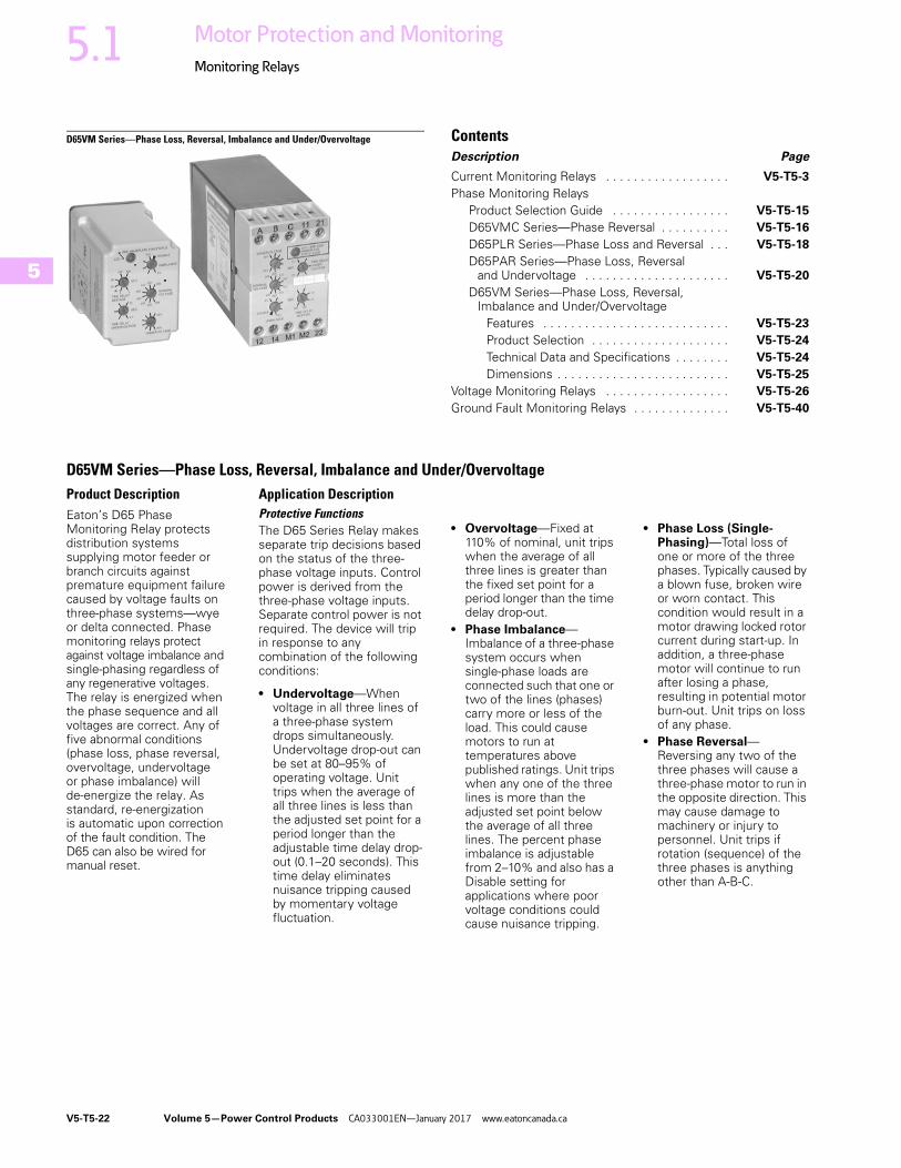
D65VM Series—Phase Loss, Reversal, Imbalance and Under/OvervoltageProduct DescriptionEaton’s D65 Phase Monitoring Relay protects distribution systems supplying motor feeder or branch circuits against premature equipment failure caused by voltage faults on three-phase systems—wye or delta connected. Phase monitoring relays protect against voltage imbalance and single-phasing regardless of any regenerative voltages. The relay is energized when the phase sequence and all voltages are correct. Any of five abnormal conditions (phase loss, phase reversal, overvoltage, undervoltage or phase imbalance) will de-energize the relay. As standard, re-energization is automatic upon correction of the fault condition. The D65 can also be wired for manual reset.
Application DescriptionProtective FunctionsThe D65 Series Relay makes separate trip decisions based on the status of the three-phase voltage inputs. Control power is derived from the three-phase voltage inputs. Separate control power is not required. The device will trip in response to any combination of the following conditions:
● Undervoltage—When voltage in all three lines of a three-phase system drops simultaneously. Undervoltage drop-out can be set at 80–95% of operating voltage. Unit trips when the average of all three lines is less than the adjusted set point for a period longer than the adjustable time delay drop-out (0.1–20 seconds). This time delay eliminates nuisance tripping caused by momentary voltage fluctuation.
● Overvoltage—Fixed at 110% of nominal, unit trips when the average of all three lines is greater than the fixed set point for a period longer than the time delay drop-out.
● Phase Imbalance—Imbalance of a three-phase system occurs when single-phase loads are connected such that one or two of the lines (phases) carry more or less of the load. This could cause motors to run at temperatures above published ratings. Unit trips when any one of the three lines is more than the adjusted set point below the average of all three lines. The percent phase imbalance is adjustable from 2–10% and also has a Disable setting for applications where poor voltage conditions could cause nuisance tripping.
● Phase Loss (Single-Phasing)—Total loss of one or more of the three phases. Typically caused by a blown fuse, broken wire or worn contact. This condition would result in a motor drawing locked rotor current during start-up. In addition, a three-phase motor will continue to run after losing a phase, resulting in potential motor burn-out. Unit trips on loss of any phase.
● Phase Reversal—Reversing any two of the three phases will cause a three-phase motor to run in the opposite direction. This may cause damage to machinery or injury to personnel. Unit trips if rotation (sequence) of the three phases is anything other than A-B-C.

Volume 5—Power Control Products CA033001EN—January 2017 www.eatoncanada.ca V5-T5-23
5
5
5
5
5
5
5
5
5
5
5
5
5
5
5
5
5
5
5
5
5
5
5
5
5
5
5
5
5
5
5.1Motor Protection and Monitoring
Monitoring Relays
Typical Connections
Line Side Monitoring
With the relay connected before the motor starter, the motor can be started in the reverse direction. However, the motor is unprotected against phase failures between the relay and the motor.
Features● Universal voltage range of
208–480V provides the flexibility to cover a variety of applications (120V and 600V units also available)
● Automatic or manual reset after the fault condition is corrected
● Multi-colour LED indicates normal condition and defines fault type for simpler troubleshooting
● D65VMLS can be either mounted directly on 35 mm DIN rail with no additional parts or to a back-panel with two screws. No socket required. D65VMLP will plug into D3PA2 socket and mount on 35 mm DIN rail
OperationThe D65 provides protection against premature equipment failure caused by voltage faults on three-phase systems. The D65 is designed to be compatible with most wye or delta systems. In wye systems, a connection to a neutral is not required. D65 Phase Monitoring Relays protect against imbalanced voltages or single-phasing regardless of any regenerative voltages. The relay is energized when the phase sequence and all voltages are correct. Any one of five fault conditions will de-energize the relay. Re-energization is automatic upon correction of the fault condition.
Manual reset is available if a NC switch is wired to the appropriate terminals. A multi-colour LED indicates normal condition and also provides specific fault indication to simplify troubleshooting. The percent phase imbalance is adjustable from 2–10%, and the undervoltage drop-out can be set at 80–95% of operating voltage. The adjustable time delay drop-out on undervoltage (0.1–20 sec.) eliminates nuisance tripping caused by momentary voltage fluctuations.
STARTL1
L1
L2
Voltage MonitorRelay
Input Fuses(Recommended)
2A Max.VoltageMonitor
Relay
3PhaseMotor
O/LSTOP
M
M
L2M
L3M
M
Load Side Monitoring
With the relay connected directly to the motor, the total feed lines are monitored. This connection should not be used with reversing motors.
● Small, compact size● User-adjustable settings
include nominal voltage, percent phase imbalance, undervoltage drop-out, time delay on undervoltage and time delay on restart after fault
LED Operation
Input Fuses(Recommended)
2A Max.
STARTL1
L1
L2
Voltage MonitorRelay
VoltageMonitor
Relay
3PhaseMotor
O/LSTOP
M
L2M
L3M
M
LED Status Indicator
Green steady Normal/relay ON
Green flashing Power-up/restart delay
Red steady Imbalance
Red flashing Undervoltage/overvoltage
Amber steady Reversal
Amber flashing Loss
Alternating green/red Undervoltage/overvoltage trip pending
Alternating red/amber Nominal voltage set error

V5-T5-24 Volume 5—Power Control Products CA033001EN—January 2017 www.eatoncanada.ca
5
5
5
5
5
5
5
5
5
5
5
5
5
5
5
5
5
5
5
5
5
5
5
5
5
5
5
5
5
5
5.1 Motor Protection and Monitoring
Monitoring Relays
Standards and Certifications● CE (Low Voltage + EMC
Directive EN60947-5-1)● cULus listed
(D65VMLS only)
● cRUus(D65VMLP only)
● RoHS compliant
● UL Listed 1
Product Selection
D65VM Series—Phase Loss, Reversal, Imbalance and Under/Overvoltage 2
Technical Data and Specifications
D65VM Series—Phase Loss, Reversal, Imbalance and Under/Overvoltage
Notes1 When used with accompanying Eaton Socket (D65VMLP only).2 Additional models available. Please visit our Web site for the latest offering.3 Requires a 600V-rated socket when used on system voltages greater than 300V. The D3PA2 socket is rated 10A, 600V.
Mounting StyleOperating Voltage50/60 Hz
CatalogueNumber
Surface-mount(DIN rail or panel)
120V D65VMLS120
208–480V D65VMLS480
600V D65VMLS600
Plug-in(DIN rail)
120V D65VMLP120
208–480V D65VMLP480 3
8-pin socket — D3PA2
8-pin IP20 rated socket — D3PA6
Description Specification
Nominal voltages(50–60 Hz)
120V, 208–480V, 575V
Connections Three-wire wye or delta
Output contacts For D65VMLS SPDT and SPNC (surface mount version only)
NO: 10A resistive at 240 Vac/30 Vdc, 1/2 hp at 240 VacNC: 10A resistive at 240 Vac/30 Vdc, 1/3 hp at 240 Vac
For D65VMLP SPDT:10A Resistive at 240 Vac/30 Vdc; 1/2 hp at 120/240 Vac
Dielectric 1000V + (2 * nominal voltage rating) between input terminals and case or active circuitry
Operating temp. –20° to 150°F (–28° to 65°C)
Response times Power up 1–300 seconds adjustable
Restart after fault 1–300 seconds adjustable
Dropout due to fault 100 ms fixed on phase loss and phase reversal;2 seconds fixed on phase imbalance;0.1–20 sec. adjustable on undervoltage only; inverse time curve for overvoltage
Mechanical life 10,000,000 operations
Electrical life 100,000 operations
Power consumption 3 VA
Net weight 10.3 oz. (292g) D65VMLS6.4 oz. (181g) D65VMLP
Hysteresis 2–3%
D65VM_

Volume 5—Power Control Products CA033001EN—January 2017 www.eatoncanada.ca V5-T5-25
5
5
5
5
5
5
5
5
5
5
5
5
5
5
5
5
5
5
5
5
5
5
5
5
5
5
5
5
5
5
5.1Motor Protection and Monitoring
Monitoring Relays
Wiring Diagrams
Surface-Mount and Plug-In
Dimensions
Approximate Dimensions in Inches (mm)
Surface-Mount and Plug-In
12 14 M2M1 22
Manual Reset
A B C
ØA ØB ØC
11 21ØA ØB ØC Manual
Reset
3
2
654
817
1.40(35.6)
0.20 (50.8) Mounting Holes – 2 Places
2.70(68.6)
1.80 (45.7)
4.40 (111.8)
4.50 (114.3)
2.40(60.1)
1.70 (43.2)
2.90 (73.7)
3.00 (76.2)
2.40(60.1)

V5-T5-26 Volume 5—Power Control Products CA033001EN—January 2017 www.eatoncanada.ca
5
5
5
5
5
5
5
5
5
5
5
5
5
5
5
5
5
5
5
5
5
5
5
5
5
5
5
5
5
5
5.1 Motor Protection and Monitoring
Monitoring Relays
Voltage Monitoring Relays ContentsDescription Page
Current Monitoring Relays . . . . . . . . . . . . . . . . . . V5-T5-3
Phase Monitoring Relays . . . . . . . . . . . . . . . . . . . V5-T5-14
Voltage Monitoring RelaysProduct Selection Guide . . . . . . . . . . . . . . . . . V5-T5-27
D65VMRP and D65VMKP Over/Undervoltage Relays (Fixed Time Delay) . . . . . . . . . . . . . . . V5-T5-28
D65VAP and D65VAKP Over/Undervoltage Relays . . . . . . . . . . . . . . . . . . . . . . . . . . . . . . . V5-T5-31
D65VWP and D65VWKP Voltage Band Relays . . . . . . . . . . . . . . . . . . . . . . . . . . . . . . V5-T5-34
VSR Series—Solid-State, Single-Phase Voltage Sensing . . . . . . . . . . . . . . . . . . . . . . . V5-T5-37
Ground Fault Monitoring Relays . . . . . . . . . . . . . . V5-T5-40
Product OverviewVoltage Monitoring Relays monitor either AC single-phase (50/60 Hz) or DC voltages to protect equipment against voltage fault conditions. No separate supply (input) voltage is required. All versions are available in a compact plug-in case using an 8-pin octal socket.
There are two styles of voltage monitoring relays:
● Over/Undervoltage Relays● Voltage Band Relays
Over/Undervoltage RelaysOver/Undervoltage Relays provide protection to equipment where either an over- or undervoltage condition is potentially damaging. Each relay can be used as either an overvoltage or an undervoltage relay, depending on the output contact used. When used as an undervoltage relay, it provides protection to equipment that is required to operate above a minimum voltage. When used as an overvoltage relay, it protects equipment against excessive voltage conditions. Over/undervoltage relays are designed to operate when the operating voltage reaches a preset value and drop out when the operating voltage drops to a level below the preset value.
Voltage Band RelaysVoltage Band Relays provide protection to equipment that is required to operate within an upper and lower voltage limit. As long as the operating voltage remains within an over- and undervoltage range, the internal relay stays energized. If the operating voltage falls outside this range, the relay will drop out.
Standards and Certifications● CE● cRUus listed● UL listed 1
● RoHS recognized
Note1 When used with accompanying Eaton
socket.

Volume 5—Power Control Products CA033001EN—January 2017 www.eatoncanada.ca V5-T5-27
5
5
5
5
5
5
5
5
5
5
5
5
5
5
5
5
5
5
5
5
5
5
5
5
5
5
5
5
5
5
5.1Motor Protection and Monitoring
Monitoring Relays
Product Selection Guide
D65V Product Family Selection—Over/Undervoltage Relays
D65V Product Family Selection—Voltage Band Relays
Note1 Fixed time delay eliminates nuisance tripping due to short voltage surges or drops.
Series PickupVoltage
DropoutVoltage
Time DelayDropout
Fixed Time Delay for Over/Undervoltage Relays
Adjustable Time Delay Over/Undervoltage Relays
D65VMP Adjustable 85–115% nominal
Fixed at 95% of pickup Fixed 500 ms 1 Page V5-T5-29 —
D65VMKP Adjustable 75–95% of pickup Page V5-T5-29 —
D65VAP Fixed at 95% of pickup Adjustable 0.5–10 seconds — Page V5-T5-32
D65VAKP Adjustable 75–95% of pickup — Page V5-T5-32
Series PickupVoltage
DropoutVoltage
Time DelayDropout Voltage Band Relays
D65VWP Adjustable 100–125% nominal
Adjustable 75–100% of nominal Fixed 500 ms 1 Page V5-T5-35
D65VWKP Adjustable 0.5–10 seconds Page V5-T5-35

V5-T5-28 Volume 5—Power Control Products CA033001EN—January 2017 www.eatoncanada.ca
5
5
5
5
5
5
5
5
5
5
5
5
5
5
5
5
5
5
5
5
5
5
5
5
5
5
5
5
5
5
5.1 Motor Protection and Monitoring
Monitoring Relays
D65VMRP and D65VMKP—Fixed Time Delay Over/Undervoltage Relays ContentsDescription Page
Current Monitoring Relays . . . . . . . . . . . . . . . . . . V5-T5-3
Phase Monitoring Relays . . . . . . . . . . . . . . . . . . . V5-T5-14
Voltage Monitoring RelaysProduct Selection Guide . . . . . . . . . . . . . . . . . V5-T5-27
D65VMRP and D65VMKP Over/Undervoltage Relays (Fixed Time Delay)
Product Selection . . . . . . . . . . . . . . . . . . . . V5-T5-29
Technical Data and Specifications . . . . . . . . V5-T5-30
Dimensions . . . . . . . . . . . . . . . . . . . . . . . . . V5-T5-30
D65VAP and D65VAKP Over/Undervoltage Relays . . . . . . . . . . . . . . . . . . . . . . . . . . . . . . . V5-T5-31
D65VWP and D65VWKP Voltage Band Relays . . . . . . . . . . . . . . . . . . . . . . . . . . . . . . V5-T5-34
VSR Series—Solid-State, Single-Phase Voltage Sensing . . . . . . . . . . . . . . . . . . . . . . . V5-T5-37
Ground Fault Monitoring Relays . . . . . . . . . . . . . . V5-T5-40
D65VMRP and D65VMKP Over/Undervoltage Relays(Fixed Time Delay)
Product DescriptionThe D65VMRP and D65VMKP Over/Undervoltage Relays provide protection to equipment where either an over- or undercurrent condition is potentially damaging. They are designed to operate when the operating voltage reaches a preset value and drop out when the operating voltage drops to a level below the preset value.
The pickup voltage setting is user-adjustable from 85–115% of the nominal voltage rating. As standard, the D65VMRP Series has a dropout voltage setting fixed at 95% of the pickup voltage setting. An adjustable drop-out setting of 75–95% of the pickup setting is available on the D65VMKP Series. The relay energizes when the monitored voltage is above the pickup setting. The relay de-energizes when the monitored voltage is below the dropout setting for a period longer than the drop-out time delay, which is fixed at 500 ms. An adjustable time delay on dropout of 0.5–10 seconds is available.
Application DescriptionEach relay can be used as either an overvoltage or an undervoltage relay, depending on the output contact used.
Overvoltage RelayProvides protection to equipment that cannot handle excess voltages. Uses a normally closed contact (NC). As long as the monitored voltage remains below the maximum voltage the equipment can withstand (pickup setting), the relay remains energized and the NC contact remains closed, keeping the load energized. If the operating voltage increases beyond the maximum rating of the equipment, the relay energizes and the NC contact opens, turning off the load. When the voltage falls below the dropout settings (hysteresis), the relay de-energizes and the NC contact re-closes, turning on the load.
Undervoltage RelayProvides protection to equipment that is required to operate above a certain minimum voltage. Uses a normally open contact (NO). As long as the monitored voltage is above the minimum value required (pickup setting), the relay will energize and the NO contact closes, turning on the load. If the voltage drops below the dropout setting (the minimum voltage required minus hysteresis), the relay will de-energize and the NO contact will re-open, turning off the load.
Features● Monitors AC single-phase
and DC voltages● Wide range of user-
adjustable pickup and dropout settings
● Fixed time delay on dropout of 500 ms
● LED indicates output relay status
● Compact plug-in case using industry standard 8-pin socket
● 10A DPDT output contacts
Fixed Time Delay Over/Undervoltage Current Monitoring
MonitoredVoltage
RelayOutput
PickupVoltage
DropoutVoltage
On
T T
Off

Volume 5—Power Control Products CA033001EN—January 2017 www.eatoncanada.ca V5-T5-29
5
5
5
5
5
5
5
5
5
5
5
5
5
5
5
5
5
5
5
5
5
5
5
5
5
5
5
5
5
5
5.1Motor Protection and Monitoring
Monitoring Relays
Product Selection
D65VMP and D65VMKP Series—Over/Undervoltage Relay 1,Adjustable Pickup, Fixed Dropout Settings 2
D65VMP and D65VMKP Series—Over/Undervoltage Relay 1,Adjustable Pickup and Dropout Settings 3
Accessories
D65VMP and D65VMKP Series—Over/Undervoltage Relays
Notes1 Time delay on dropout fixed at 500 ms.2 Dropout voltage is fixed at 95% of the adjusted pickup setting.3 Dropout voltage is adjustable from 75–95% of the adjusted pickup setting.
NominalVoltage
Voltage Range CatalogueNumberPickup Dropout
24 Vac 21–27 Vac 20–26 Vac D65VMRPT
120 Vac 102–138 Vac 97–131 Vac D65VMRPA
12 Vdc 10–14 Vdc 9–13 Vdc D65VMRPR1
24 Vdc 21–27 Vdc 20–26 Vdc D65VMRPT1
48 Vdc 41–55 Vdc 39–52 Vdc D65VMRPW1
110 Vdc 94–126 Vdc 89–121 Vdc D65VMRPA1
NominalVoltage
Voltage Range CatalogueNumberPickup Dropout
24 Vac 21–27 Vac 16–26 Vac D65VMKPT
120 Vac 102–138 Vac 77–131 Vac D65VMKPA
12 Vdc 10–14 Vdc 8–13 Vdc D65VMKPR1
24 Vdc 21–27 Vdc 16–26 Vdc D65VMKPT1
48 Vdc 41–55 Vdc 32–52 Vdc D65VMKPW1
110 Vdc 94–126 Vdc 71–121 Vdc D65VMKPA1
D65VM_
D65VM_
DescriptionStandard Pack
CatalogueNumber
8-pin socket 10 D3PA2
Hold-down spring 10 D65CHDS

V5-T5-30 Volume 5—Power Control Products CA033001EN—January 2017 www.eatoncanada.ca
5
5
5
5
5
5
5
5
5
5
5
5
5
5
5
5
5
5
5
5
5
5
5
5
5
5
5
5
5
5
5.1 Motor Protection and Monitoring
Monitoring Relays
Technical Data and Specifications
D65V Series—Fixed and Adjustable Time Delay Over/Undervoltage Relays
D65VMP, D65VMKP, D65VAP and D65VAKP Series, Over/Undervoltage Relays
Wiring Diagram
Wiring for 8-Pin Socket
DimensionsApproximate Dimensions in Inches (mm)
D65V Series—Fixed and Adjustable Time Delay Over/Undervoltage Relays
Description Specification
Voltage tolerance +25%/–50% of nominal voltage; AC voltages are 50/60 Hz No supply (input) voltage is required
Load (burden) Less than 3 VA
Current settings Pickup Adjustable from 85–115% of nominal voltage
Dropout Fixed at 95% of the pickup setting for D65VMP and D65VAPAdjustable from 75–95% of the pickup setting for D65VMKP and D65VAKP
Temperature –20° to 131°F (–28° to 55°C)
Response times Pickup 500 ms
Dropout Fixed 500 ms for D65VMP and D65VMKPAdjustable 0.5–10 seconds for D65VAP and D65VAKP
Output contacts 10A Resistive at 240 Vac/30 Vdc, 1/2 hp at 240 Vac (NO), 1/3 hp at 240 Vac (NC)
Mechanical life 10,000,000 operations
Electrical life 100,000 operations
Indicator LED Red steady when relay is energized; green when relay is OFF
Transient protection 10,000 volts for 20 microseconds
Reset Automatic
Mounting Requires an 8-pin socket
MonitoredVoltage
1
(DC)+L1
(DC)−L2
8
4
3 6
2 7
5
2.4(60)
1.7(43)
2.9(74)
3.5(89)
D65VMKP andD65VAKP Only

Volume 5—Power Control Products CA033001EN—January 2017 www.eatoncanada.ca V5-T5-31
5
5
5
5
5
5
5
5
5
5
5
5
5
5
5
5
5
5
5
5
5
5
5
5
5
5
5
5
5
5
5.1Motor Protection and Monitoring
Monitoring Relays
D65VAP & D65VAKP—Adjustable Time Delay Over/Undervoltage Relays ContentsDescription Page
Current Monitoring Relays . . . . . . . . . . . . . . . . . . . V5-T5-3
Phase Monitoring Relays . . . . . . . . . . . . . . . . . . . . V5-T5-14
Voltage Monitoring RelaysProduct Selection Guide . . . . . . . . . . . . . . . . . . V5-T5-27
D65VMRP and D65VMKP Over/Undervoltage Relays (Fixed Time Delay) . . . . . . . . . . . . . . . V5-T5-28
D65VAP and D65VAKP Over/Undervoltage Relays (Adjustable Time Delay)
Product Selection . . . . . . . . . . . . . . . . . . . . V5-T5-32
Technical Data and Specifications . . . . . . . . V5-T5-33
Dimensions . . . . . . . . . . . . . . . . . . . . . . . . . V5-T5-33
D65VWP and D65VWKP Voltage Band Relays . . . . . . . . . . . . . . . . . . . . . . . . . . . . . . V5-T5-34
VSR Series—Solid-State, Single-Phase Voltage Sensing . . . . . . . . . . . . . . . . . . . . . . . V5-T5-37
Ground Fault Monitoring Relays . . . . . . . . . . . . . . V5-T5-40
D65VAP and D65VAKP Over/Undervoltage Relays(Adjustable Time Delay)
Product DescriptionThe D65VAP and D65VAKP Over/Undervoltage Relays provide protection to equipment where either an over- or undercurrent condition is potentially damaging. They are designed to operate when the operating voltage reaches a preset value and drop out when the operating voltage drops to a level below the preset value.
The pickup voltage setting is user-adjustable from 85–115% of the nominal voltage rating. As standard, the D65VAP Series has a dropout voltage setting fixed at 95% of the pickup voltage setting. An adjustable dropout setting of 75–95% of the pickup setting is available on the D65VAKP Series. The relay energizes when the monitored voltage is above the pickup setting. The relay de-energizes when the monitored voltage is below the dropout setting for a period longer than the dropout time delay, which is adjustable from 0.5–10 seconds. A fixed time delay of 500 ms is available with the D65VMP Series.
Application DescriptionEach relay can be used as either an overvoltage or an undervoltage relay, depending on the output contact used.
Overvoltage RelayProvides protection to equipment that cannot handle excess voltages. Uses a normally closed contact (NC). As long as the monitored voltage remains below the maximum voltage the equipment can withstand (pickup setting), the relay remains energized and the NC contact remains closed, keeping the load energized. If the operating voltage increases beyond the maximum rating of the equipment, the relay energizes and the NC contact opens, turning off the load. When the voltage falls below the dropout settings (hysteresis), the relay de-energizes and the NC contact re-closes, turning on the load.
Undervoltage RelayProvides protection to equipment that is required to operate above a certain minimum voltage. Uses a normally open contact (NO). As long as the monitored voltage is above the minimum value required (pickup setting), the relay will energize and the NO contact closes, turning on the load. If the voltage drops below the dropout setting (the minimum voltage required minus hysteresis), the relay will de-energize and the NO contact will re-open, turning off the load.
Features● Monitors AC single-phase
and DC voltages● Wide range of user-
adjustable pickup and dropout settings
● Adjustable time delay on dropout of 0.5–10 seconds
● LED indicates output relay status
● Compact plug-in case using industry standard 8-pin socket
● 10A DPDT output contacts
Adjustable Time Delay Over/Undervoltage Current Monitoring
MonitoredVoltage
RelayOutput
PickupVoltage
DropoutVoltage
On
T T
Off

V5-T5-32 Volume 5—Power Control Products CA033001EN—January 2017 www.eatoncanada.ca
5
5
5
5
5
5
5
5
5
5
5
5
5
5
5
5
5
5
5
5
5
5
5
5
5
5
5
5
5
5
5.1 Motor Protection and Monitoring
Monitoring Relays
Product Selection
D65VAP and D65VAKP Series—Over/Undervoltage Relay 1,Adjustable Pickup, Fixed Dropout Settings 2
D65VAP and D65VAKP Series—Over/Undervoltage Relay 1,Adjustable Pickup and Dropout Settings 3
Accessories
D65VMP and D65VMKP Series—Over/Undervoltage Relays
Notes1 Time delay on dropout fixed at 500 ms.2 Dropout voltage is fixed at 95% of the adjusted pickup setting.3 Dropout voltage is adjustable from 75–95% of the adjusted pickup setting.
NominalVoltage
Voltage Range CatalogueNumberPickup Dropout
24 Vac 21–27 Vac 20–26 Vac D65VAPT
120 Vac 102–138 Vac 97–131 Vac D65VAPA
12 Vdc 10–14 Vdc 9–13 Vdc D65VAPR1
24 Vdc 21–27 Vdc 20–26 Vdc D65VAPT1
48 Vdc 41–55 Vdc 39–53 Vdc D65VAPW1
110 Vdc 94–126 Vdc 89–121 Vdc D65VAPA1
NominalVoltage
Voltage Range CatalogueNumberPickup Dropout
24 Vac 21–27 Vac 16–26 Vac D65VAKPT
120 Vac 102–138 Vac 77–131 Vac D65VAKPA
12 Vdc 10–14 Vdc 8–13 Vdc D65VAKPR1
24 Vdc 21–27 Vdc 16–26 Vdc D65VAKPT1
48 Vdc 41–55 Vdc 32–52 Vdc D65VAKPW1
110 Vdc 94–126 Vdc 71–121 Vdc D65VAKPA1
D65VA_
D65VA_
DescriptionStandard Pack
CatalogueNumber
8-pin socket 10 D3PA2
Hold-down spring 10 D65CHDS

Volume 5—Power Control Products CA033001EN—January 2017 www.eatoncanada.ca V5-T5-33
5
5
5
5
5
5
5
5
5
5
5
5
5
5
5
5
5
5
5
5
5
5
5
5
5
5
5
5
5
5
5.1Motor Protection and Monitoring
Monitoring Relays
Technical Data and Specifications
D65V Series—Fixed and Adjustable Time Delay Over/Undervoltage Relays
D65VMP, D65VMKP, D65VAP and D65VAKP Series, Over/Undervoltage Relays
Wiring Diagram
Wiring for 8-Pin Socket
DimensionsApproximate Dimensions in Inches (mm)
D65V Series—Fixed and Adjustable Time Delay Over/Undervoltage Relays
Description Specification
Voltage tolerance +25%/–50% of nominal voltage; AC voltages are 50/60 Hz No supply (input) voltage is required
Load (burden) Less than 3 VA
Current settings Pickup Adjustable from 85–115% of nominal voltage
Dropout Fixed at 95% of the pickup setting for D65VMP and D65VAPAdjustable from 75–95% of the pickup setting for D65VMKP and D65VAKP
Temperature –20° to 131°F (–28° to 55°C)
Response times Pickup 500 ms
Dropout Fixed 500 ms for D65VMP and D65VMKPAdjustable 0.5–10 seconds for D65VAP and D65VAKP
Output contacts 10A resistive at 240 Vac/30 Vdc, 1/2 hp at 240 Vac (NO), 1/3 hp at 240 Vac (NC)
Mechanical life 10,000,000 operations
Electrical life 100,000 operations
Indicator LED Red steady when relay is energized; green when relay is OFF
Transient protection 10,000 volts for 20 microseconds
Reset Automatic
Mounting Requires an 8-pin socket
MonitoredVoltage
1
(DC)+L1
(DC)−L2
8
4
3 6
2 7
5
2.4(60)
1.7(43)
2.9(74)
3.5(89)
D65VMKP andD65VAKP Only

V5-T5-34 Volume 5—Power Control Products CA033001EN—January 2017 www.eatoncanada.ca
5
5
5
5
5
5
5
5
5
5
5
5
5
5
5
5
5
5
5
5
5
5
5
5
5
5
5
5
5
5
5.1 Motor Protection and Monitoring
Monitoring Relays
D65VWP and D65VWKP Voltage Band Relays ContentsDescription Page
Current Monitoring Relays . . . . . . . . . . . . . . . . . . V5-T5-3
Phase Monitoring Relays . . . . . . . . . . . . . . . . . . . V5-T5-14
Voltage Monitoring RelaysProduct Selection Guide . . . . . . . . . . . . . . . . . V5-T5-27
D65VMRP and D65VMKP Over/Undervoltage Relays (Fixed Time Delay) . . . . . . . . . . . . . . . V5-T5-28
D65VAP and D65VAKP Over/Undervoltage Relays (Adjustable Time Delay) . . . . . . . . . . . V5-T5-31
D65VWP and D65VWKP Voltage Band Relays Product Selection . . . . . . . . . . . . . . . . . . . . V5-T5-35
Technical Data and Specifications . . . . . . . . V5-T5-36
Dimensions . . . . . . . . . . . . . . . . . . . . . . . . . V5-T5-36
VSR Series—Solid-State, Single-Phase Voltage Sensing . . . . . . . . . . . . . . . . . . . . . . . V5-T5-37
Ground Fault Monitoring Relays . . . . . . . . . . . . . . V5-T5-40
D65VWP and D65VWKP Voltage Band RelaysProduct DescriptionThe D65VWP and D65VWKP Series Voltage Band Relays provide protection to equipment that is required to operate within an upper and lower voltage limit. As long as the operating voltage remains within an over- and undervoltage range, the internal relay stays energized. If the operating voltage falls outside this range, the relay will drop out.
When nominal operating voltage is applied, the internal relay will energize (pickup). If the operating voltage falls outside the preset over trip point (adjustable 100–125% of nominal), or under trip point (adjustable 75–100% of nominal), for a period longer than the dropout time delay, the relay will de-energize (dropout). When the voltage returns to normal (within the preset over- and undervoltage trip points), the unit automatically resets and the relay energizes. Choose between a unit with fixed dropout time of 500 ms or one with an adjustable 0.5–10 seconds dropout time.
Features● Monitors AC single-phase
and DC voltages● Provides voltage band
(window) protection● Wide range of user-
adjustable overvoltage and undervoltage settings
● Fixed or adjustable time delay on dropout
● LED indicates output relay status
● Compact plug-in case using industry standard 8-pin octal socket
● 10A DPDT output contacts
Voltage Band Relay Current Monitoring
T
MonitoredCurrent
OverVoltage
UnderVoltage
RelayOutput
ON
OFF T T T
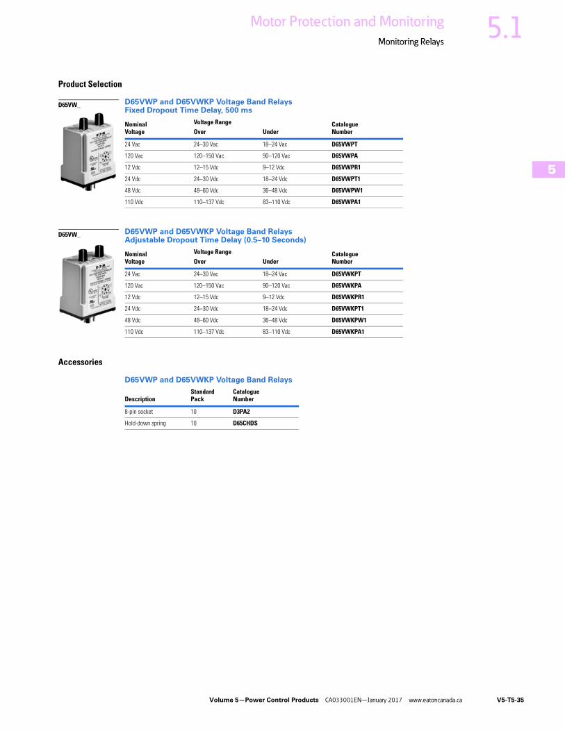
Volume 5—Power Control Products CA033001EN—January 2017 www.eatoncanada.ca V5-T5-35
5
5
5
5
5
5
5
5
5
5
5
5
5
5
5
5
5
5
5
5
5
5
5
5
5
5
5
5
5
5
5.1Motor Protection and Monitoring
Monitoring Relays
Product Selection
D65VWP and D65VWKP Voltage Band RelaysFixed Dropout Time Delay, 500 ms
D65VWP and D65VWKP Voltage Band RelaysAdjustable Dropout Time Delay (0.5–10 Seconds)
Accessories
D65VWP and D65VWKP Voltage Band Relays
NominalVoltage
Voltage Range CatalogueNumberOver Under
24 Vac 24–30 Vac 18–24 Vac D65VWPT
120 Vac 120–150 Vac 90–120 Vac D65VWPA
12 Vdc 12–15 Vdc 9–12 Vdc D65VWPR1
24 Vdc 24–30 Vdc 18–24 Vdc D65VWPT1
48 Vdc 48–60 Vdc 36–48 Vdc D65VWPW1
110 Vdc 110–137 Vdc 83–110 Vdc D65VWPA1
NominalVoltage
Voltage Range CatalogueNumberOver Under
24 Vac 24–30 Vac 18–24 Vac D65VWKPT
120 Vac 120–150 Vac 90–120 Vac D65VWKPA
12 Vdc 12–15 Vdc 9–12 Vdc D65VWKPR1
24 Vdc 24–30 Vdc 18–24 Vdc D65VWKPT1
48 Vdc 48–60 Vdc 36–48 Vdc D65VWKPW1
110 Vdc 110–137 Vdc 83–110 Vdc D65VWKPA1
D65VW_
D65VW_
DescriptionStandard Pack
CatalogueNumber
8-pin socket 10 D3PA2
Hold-down spring 10 D65CHDS

V5-T5-36 Volume 5—Power Control Products CA033001EN—January 2017 www.eatoncanada.ca
5
5
5
5
5
5
5
5
5
5
5
5
5
5
5
5
5
5
5
5
5
5
5
5
5
5
5
5
5
5
5.1 Motor Protection and Monitoring
Monitoring Relays
Technical Data and Specifications
D65VWP and D65VWPK Series, Voltage Band Relays
Wiring Diagram
Wiring for 8-Pin Socket
DimensionsApproximate Dimensions in Inches (mm)
D65VWP and D65VWPK Series, Voltage Band Relays
Description Specification
Voltage tolerance +25%/–50% of nominal voltage; AC voltages are 50/60 Hz No separate supply (input) voltage is required
Load (burden) Less than 3 VA
Voltage settings Overvoltage 100–125% of nominal voltage
Undervoltage 75–100% of nominal voltage
Temperature –20° to 131°F (–28° to 55°C)
Indicator LED Red steady when relay is energized; green when relay is OFF
Reset AutomaticContact Eaton for information on how to order a unit with manual reset
Response times Operate 500 ms
Release Fixed 500 ms (D65VWP Series)Adjustable 0.5–10 seconds (D65VWKP Series)
Output contacts 10A resistive at 240 Vac/30 Vdc, 1/2 hp at 240 Vac (NO), 1/3 hp at 240 Vac (NC)
Mechanical life 10,000,000 operations
Electrical life 100,000 operations
Transient protection 10,000 volts for 20 microseconds
MonitoredVoltage
1
(DC)+L1
(DC)−L2
8
4
3 6
2 7
5
2.4(60)
1.7(43)
2.9(74)
3.5(89)
D65VWKPOnly

Volume 5—Power Control Products CA033001EN—January 2017 www.eatoncanada.ca V5-T5-37
5
5
5
5
5
5
5
5
5
5
5
5
5
5
5
5
5
5
5
5
5
5
5
5
5
5
5
5
5
5
5.1Motor Protection and Monitoring
Monitoring Relays
VSR Series—Solid-State, Single-Phase Voltage Sensing ContentsDescription Page
Current Monitoring Relays . . . . . . . . . . . . . . . . . . . V5-T5-3
Phase Monitoring Relays . . . . . . . . . . . . . . . . . . . . V5-T5-14
Voltage Monitoring RelaysProduct Selection Guide . . . . . . . . . . . . . . . . . . V5-T5-27
D65VMRP and D65VMKP Over/Undervoltage Relays (Fixed Time Delay) . . . . . . . . . . . . . . . V5-T5-28
D65VAP and D65VAKP Over/Undervoltage Relays (Adjustable Time Delay) . . . . . . . . . . . V5-T5-31
D65VWP and D65VWKP Voltage Band Relays . . . . . . . . . . . . . . . . . . . . . . . . . . . . . . V5-T5-34
VSR Series—Solid-State, Single-Phase Voltage Sensing
Product Selection . . . . . . . . . . . . . . . . . . . . V5-T5-37
Technical Data and Specifications . . . . . . . . V5-T5-38
Dimensions . . . . . . . . . . . . . . . . . . . . . . . . . V5-T5-39
Ground Fault Monitoring Relays . . . . . . . . . . . . . . V5-T5-40
VSR Series—Solid-State, Single-Phase Voltage SensingProduct DescriptionThe Catalogue Number VSR voltage sensing relays are highly accurate, solid-state, AC voltage sensing devices available in both overvoltage and undervoltage types. They include built-in locking shaft potentiometers for voltage and differential adjustment.
Relay circuit boards are conformal contact for environment-free operation. Input is transformer isolated from solid-state output contact. Mounting dimensions are the same as Catalogue Number BF relays.
Features● Same base plate as
Catalogue Number BF relay, mounts in same area
● Captive, pressure clamp terminals—accept 1 or 2 solid or stranded 14 AWG or smaller wires
● Adjustment potentiometer with locking shafts—provides shock-proof adjustment
● Conformal coated printed circuit board—protects relay against shock, moisture, dirt and other environmental hazards
● Built-in surge protection—protects internal solid-state contact from damage due to load and line transients
Product SelectionWhen Ordering, Specify ● Catalogue Number of Basic Relay
Voltage Sensing Relays—Undervoltage
Voltage Sensing Relays—Overvoltage
Voltage RangeCatalogue Number
70–120 Vac VSRUA
200–280 Vac VSRUB
Voltage RangeCatalogue Number
100–140 Vac VSROA
200–280 Vac VSROB
VSRU_
VSRO_

V5-T5-38 Volume 5—Power Control Products CA033001EN—January 2017 www.eatoncanada.ca
5
5
5
5
5
5
5
5
5
5
5
5
5
5
5
5
5
5
5
5
5
5
5
5
5
5
5
5
5
5
5.1 Motor Protection and Monitoring
Monitoring Relays
Technical Data and Specifications
VSR Series—Solid-State, Single-Phase Voltage Sensing
Operating Curves—Undervoltage Relay
Solid-state NO contact closes when voltage exceeds upper limit set by voltage adjustment potentiometer. Contact remains closed until voltage drops below the value set with differential adjustment. Contact will not reclose until voltage once again exceeds upper limit.
Operating Curves—Overvoltage Relay
Providing a minimum of 60V input is present, solid-state contact is NC. Differential adjustment sets upper limit where contact will open. After opening, contact will remain open until voltage drops below value set with voltage adjustment potentiometer.
Relay Pick-Up and Drop-Out Voltage Ranges—Undervoltage
Relay Pick-Up and Drop-Out Voltage Ranges—Overvoltage
Notes1 Can initiate a Size 4 motor starter.2 12A rms maximum inrush for three cycles. If inrush current is greater than 12A and relay is
operated more than 30 times per minute, derating may be necessary. If surge current is 12A or less, no derating is necessary. If currents exceeding these ratings could occur, a series fuse having an I2t rating equal to 3A squared seconds is recommended.
3 For operation in a higher ambient temperature, derating may be necessary.
Description Specification
Electrical ratings Operating voltage range 70–140 Vac, 200–280 Vac 3 VA burden
Variable differential range See Operating Curves below
Repeatability ±0.5 Vac of setting
Solid-state contacts 2A continuous maximum inductive or resistive, 132 Vac maximum 12
Ambient temperature range 3 –4° to 140°F (–20° to 60°C)
Open contact leakage current 3 mA maximum
Closed contact voltage drop 3 Vac maximum
20
0 V
olt
s
Min
imu
m
70
Vo
lts
28
0 V
olt
s12
0 V
olt
sto
Lin
e V
olt
s
to
Relay ContactStatus Dropping
Voltage
Relay Contact StatusRising Voltage
CW
CCW
CCW
CW
Voltage Adjustment(Pickup)
DifferentialAdjustment(Dropout)
1 Volt MinimumRecommended
Differential
Ma
xim
um
0 VoltsPotentiometer Rotation
Dropout Voltage (Variable Between70 Vac and1 Vac Less ThanPickup Voltage)
Diff. Adj. Max. CW
1 Vac
Diff. Adj.Max. CCW
0 50
% Rotation Voltage Adj. Control
100
120or 280
70or 200
Lin
e V
olt
ag
e (
VA
-C)
on
Te
rmin
als
1 &
2
Pickup Voltage (Variablefrom 70 to 120 Vacor 200 to 280 Vac)
Diff. Adj. Max. CW
Pickup Voltage(Variable from100 to 137 Vac
or 200 Vac)
Dropout Voltage(Variable Between3 Vac More Than
Pickup Voltage and140 Vac)
0 50
% Rotation Voltage Adj. Control
100
140or 280
100or 200 3 Vac
Diff. Adj.Max. CCW
Lin
e V
olt
ag
e (
VA
-C)
on
Te
rmin
als
1 &
2

Volume 5—Power Control Products CA033001EN—January 2017 www.eatoncanada.ca V5-T5-39
5
5
5
5
5
5
5
5
5
5
5
5
5
5
5
5
5
5
5
5
5
5
5
5
5
5
5
5
5
5
5.1Motor Protection and Monitoring
Monitoring Relays
DimensionsApproximate Dimensions in Inches (mm)
VSR Series—Solid-State, Single-Phase Voltage Sensing
4.69 (119.1)0.5 (12.7)
Catalogue Number VSR
3.13(79.5)
1 (25.4)
2.81(71.4)
0.16(4.1)
1.63(41.4)
0.81(20.6)
Voltage Input:Terminals 1 and 2
Solid-State Output:Terminals 3 and 4
0.17 (4.3) Dia.3 Mtg. Slots
LockNut

V5-T5-40 Volume 5—Power Control Products CA033001EN—January 2017 www.eatoncanada.ca
5
5
5
5
5
5
5
5
5
5
5
5
5
5
5
5
5
5
5
5
5
5
5
5
5
5
5
5
5
5
5.1 Motor Protection and Monitoring
Monitoring Relays
Ground Fault Relays and Monitors ContentsDescription Page
Current Monitoring Relays . . . . . . . . . . . . . . . . . . V5-T5-3
Phase Monitoring Relays . . . . . . . . . . . . . . . . . . . V5-T5-14
Voltage Monitoring Relays . . . . . . . . . . . . . . . . . . V5-T5-26
Ground Fault Relays and MonitorsD64R Series—Digital Ground Fault Relays . . . . V5-T5-41
D64L Series—Ground Fault Monitors . . . . . . . V5-T5-51
Product OverviewD64R Series—Digital Ground Fault RelaysThe new D64R digital ground fault relays are microprocessor-based and replace the previous generation of analogue-based devices.
Microprocessor-based D64R GFRs combine more selectable features into a single model, which makes easier model selection and reduces spares inventory requirements.
These devices are designed to provide reliable detection of ground fault conditions on three-phase AC resistance grounded or solidly grounded electrical distribution systems.
D64L Series—Ground Fault MonitorsType D64L ground fault monitors are designed to monitor ungrounded supplies on three-phase AC power systems up to 600V. If an insulation fault develops anywhere on the system between the source and the load, the D64L will detect it and give an alarm or trip, depending on the adjustable field settings selected.
The D64L is ideally suited for systems supplied from the secondary of either an ungrounded delta or an ungrounded wye connected transformer.
Because D64L has high immunity from the effects of voltage transients and cable capacitance, it may be applied in automotive, sub-sea, mobile lighting, portable generators, sensitive equipment and other installations where ungrounded systems are used extensively.
The user is able to individually set the alarm level and the trip level from 20%–80% of the maximum leakage current limit of the D64L selected. Any leakage current above the alarm level will activate the alarm relay and light the alarm LED. Should the leakage current rise above the trip level, the trip relay and trip LED will activate.

Volume 5—Power Control Products CA033001EN—January 2017 www.eatoncanada.ca V5-T5-41
5
5
5
5
5
5
5
5
5
5
5
5
5
5
5
5
5
5
5
5
5
5
5
5
5
5
5
5
5
5
5.1Motor Protection and Monitoring
Monitoring Relays
D64R Series—Digital Ground Fault Relays ContentsDescription Page
Current Monitoring Relays . . . . . . . . . . . . . . . . . . . V5-T5-3
Phase Monitoring Relays . . . . . . . . . . . . . . . . . . . . V5-T5-14
Voltage Monitoring Relays . . . . . . . . . . . . . . . . . . . V5-T5-26
Ground Fault Relays and MonitorsD64R Series—Digital Ground Fault Relays
Features . . . . . . . . . . . . . . . . . . . . . . . . . . . V5-T5-42
Options . . . . . . . . . . . . . . . . . . . . . . . . . . . . V5-T5-42
Standards and Certifications . . . . . . . . . . . . V5-T5-42
Product Selection . . . . . . . . . . . . . . . . . . . . V5-T5-43
Accessories . . . . . . . . . . . . . . . . . . . . . . . . . V5-T5-44
Technical Data and Specifications . . . . . . . . V5-T5-45
Wiring Diagrams . . . . . . . . . . . . . . . . . . . . . V5-T5-46
Dimensions . . . . . . . . . . . . . . . . . . . . . . . . . V5-T5-48
D64L Series—Ground Fault Monitors . . . . . . . V5-T5-51
D64R Series—Digital Ground Fault RelaysProduct DescriptionThe new D64R digital ground fault relays are microprocessor-based and replace the previous generation of analogue-based devices.
Microprocessor-based D64R GFRs combine more selectable features into a single model, which makes easier model selection and reduces spares inventory requirements.
These devices are designed to provide reliable detection of ground fault conditions on three-phase AC resistance grounded or solidly grounded electrical distribution systems.
Application DescriptionD64R ground fault relays feature adjustable trip settings for both trip current and trip time. This allows the user to set the ground fault trip current just above the “charging” current of the system. This prevents nuisance tripping and provides meaningful protection of additional ground fault leakage currents.
Every system has a “charging” current that can cause nuisance tripping if the trip current is set too low. The “charging” current is caused by the capacitance-to-ground effect of phase conductors in a system and will vary depending on:
● The overall length of the cables
● The types of loads● The quality of the
insulation on the phase conductors
● Surrounding equipment grounding, cable trays, junction boxes, and so on
● Type and size of transformer
A “rule-of-thumb” for systems 600V and lower: the “charging” current is 0.5A per 1000 kVA of transformer capacity.

V5-T5-42 Volume 5—Power Control Products CA033001EN—January 2017 www.eatoncanada.ca
5
5
5
5
5
5
5
5
5
5
5
5
5
5
5
5
5
5
5
5
5
5
5
5
5
5
5
5
5
5
5.1 Motor Protection and Monitoring
Monitoring Relays
FeaturesStandard Models● Built-in current sensor
(zero sequence CT)● Run and trip indicating
LEDs● Built-in harmonic filtering
for variable frequency drives or standard 50/60 Hz applications (see Page V5-T5-45 for frequency response range)
● DIN rail or panel mounting● Rugged epoxy
encapsulated construction● Pull-apart terminal block
connectors● Form “Z” (4 terminal) NO
and NC output contacts, 5 amps at 250 Vac
● Pulsed (trip) auto reset mode
The pulsed (trip) auto reset mode is designed for applications where the output relay is operating a shunt trip device. The D64R relay resets automatically, three seconds after the ground fault current is interrupted by the tripping action of the circuit breaker. This opens the output contact wired to the shunt trip coil and prevents damage to the internal mechanism of the circuit breaker in the event that the operator tries to reset the circuit breaker.
● Suitable for use on 600V systems—may be applied on higher voltages by using separate CTs with power conductors insulated for the system voltage
● Built-in test circuitry—no external power or additional wiring is necessary—tests trip time and current settings
● Communications port (standard RJ-10 jack) for connection to optional remote display (D64D1) and door mounted units (on D64RPB100 models only)
● Fail-safe selectable mode (on D64RPB100 models only)
In the fail-safe mode, the relay is energized when control voltage is applied and will trip when either:
● a ground fault trip is detected or,
● there is a loss of control power.
Service Protection Models● Service protection models
require C311CT 10,000:1 ratio CTs
● Trip current range of 50 to 1200A
● Green LED indicates “Power On”
● Circuit breaker toggle position indicates “Normal” or “Tripped” condition
● Form “C” (3 terminal) NO-NC output contacts, 3 amps at 250 Vac
● Frequency response range of 40 to 200 Hz
● Zone interlocking feature with green LED to indicate “Grading Input Active” and DIP switch array for zone grading backup delay and block signal override (on D64RPBH15 model only)
● Test button to invoke test at 20A trip current—tests external CT, electronics and circuit breaker trip
● Fail-safe selectable mode (see above for description)
● Inhibit selectable mode—this allows the relay to differentiate between normal ground fault trip levels and short circuit conditions
The trip inhibit function is useful when the relay is being used to trip a contactor or motor starter on a solidly grounded system. Under a bolted fault condition, the relay would trip and could cause the contactor or motor starter to interrupt the high fault current with harmful results. By inhibiting the trip, the ground fault relay will not trip on bolted faults and will allow the upstream protective device to clear the fault instead.
● Through-the-door or rear panel mounting
Options● Other ranges of trip
currents and times● Fixed trip current and times● Other control voltages● Custom packaging for
volume OEM requirements● Separate outputs for
alarming vs trip● Relays for neutral
grounding resistance monitoring
● Other sizes of current transformers
Standards and Certifications● UL 1053
● Ground Fault Sensing and Relaying Equipment, Class 1(UL File # E195341)
● CSA® C22.2 No. 144-M91● Ground Fault Circuit
Interrupters (CSA File # 700103)
● CE Mark—Declaration of Conformity
● IEC 60755● General Requirements
for residual current operated protective devices
● EN 50081-1● Electromagnetic
compatibility (radiated emission), “household” directive
D64R ground fault relays are UL listed as Class 1 devices designed to protect electrical equipment against extensive damage from arcing ground faults.

Volume 5—Power Control Products CA033001EN—January 2017 www.eatoncanada.ca V5-T5-43
5
5
5
5
5
5
5
5
5
5
5
5
5
5
5
5
5
5
5
5
5
5
5
5
5
5
5
5
5
5
5.1Motor Protection and Monitoring
Monitoring Relays
Product Selection
Standard Models When Ordering, Specify● Catalogue number of relay from tables● Catalogue number of zero sequence current transformers, if or when required,
remote digital display or remote indicator units
Ground Fault Relay with Built-In Current Sensor
Service Protection ModelsWhen Ordering, Specify● Catalogue number of relay from tables● Catalogue number of zero sequence current transformers, if or when required,
remote digital display or remote indicator units
Ground Fault Relay
Notes1 Maximum allowable continuous current through built-in CT is 100 amps.2 For 500:1 ratio CTs, select from Protective Relays in Volume 3—Power Distribution and Control Assemblies,
CA08100004E. Tab 9, section 9.3.3 Maximum allowable continuous current through built-in CT is 200 amps.4 For 500:5 or 5000:5 ratio CTs, select any commercially available 5 amp secondary CT with the same ratio.5 For 10,000: 1 ratio CTs, select from Protective Relays in Volume 3—Power Distribution and Control Assemblies,
CA08100004E. Tab 9, section 9.3.
Control PowerTrip CurrentRange
Current TransformerSelection
CatalogueNumber
24–240 Vac/Vdc 30 mA–6A Built-in 1.1 in CT 1If external CT is required for specific application, select 500:1 ratio CT 2
D64RP18
24–240 Vac/Vdc 30 mA–9A Built-in 2.0 in CT 3If external CT is required for specific application, select 500:1 ratio CT 2
D64RPB100_
3A–900A Select 500:5 ratio CT 4 D64RPB100_
30A–9000A Select 5000:5 ratio CT 4 D64RPB100_
24–240 Vac/Vdc 30 mA–9A Requires use of applicable C331CT, see Page V5-T5-44.
D64RPB30
D64RP18without Plug-In
D64RPB100 Full-Featured Ground Fault Relay
D64RPB30without Internal CT
ControlPower
ZoneInterlockingFeature
Trip CurrentRange
Current TransformerSelection
CatalogueNumber
120 Vac No 50A–1200A Select 10,000:1 ratio CT 5 D64RPBH13
120 Vac Yes 50A–1200A Select 10,000:1 ratio CT 5 D64RPBH15
D64RPBH15 Ground Fault Relay with Zone Interlocking

V5-T5-44 Volume 5—Power Control Products CA033001EN—January 2017 www.eatoncanada.ca
5
5
5
5
5
5
5
5
5
5
5
5
5
5
5
5
5
5
5
5
5
5
5
5
5
5
5
5
5
5
5.1 Motor Protection and Monitoring
Monitoring Relays
Accessories
Zero Sequence Current Transformers ● A complete size range of
zero sequence CTs designed specifically for use with D64R relays provide excellent coupling to the monitored circuit. This means accurate ground fault leakage current detection over the full setting range of the relay with no saturation
● Built-in back-to-back zeners across the output terminals of all 500:1 and 10,000:1 CTs provide personnel safety should the secondary circuit be opened
● Rectangular split core CTs make retro-fitting easy
● All CTs are epoxy potted, panel mounted and come with either secondary screw terminals or threaded studs
● The core is very high grade silicon iron to give superior coupling characteristics and to withstand high shock and vibration
● All CTs are 600 Volt class. They may be used on higher voltage circuits provided that power conductors are insulated for the system voltage
Zero Sequence Current Transformers for D64RP18 and D64RPB100 Relay 123
Toroidal
Split Core (Rectangular/Square)
Zero Sequence Current Transformers for D64RPBH13 and D64RPBH15 Relays
Toroidal
Notes1 D64RP18 relays use 500:1 ratio CTs if needed.2 D64RPB100 relays can use 500:1 ratio CTs when needed for 30 mA–9A,
500:5 ratio for 3A–900A and 5000:5 ratio for 30A–9000A trip current ranges.3 For 500:5 or 5000:5 ratio CTs, select any commercially available 5 Amp
secondary CT with the same ratio.4 The maximum allowable continuous current through CTs is 1000A.5 The maximum allowable continuous current through 10,000:1 ratio CTs is 10,000A.
Description/Window Size
Ratio 500:1 CTs 4
Catalogue Number
1.1 in (28 mm) C311CT8
1.8 in (46 mm) C311CT1
2.5 in (65 mm) C311CT9
3.5 in (90 mm) C311CT2
5.7 in (144 mm) C311CT5
9.5 in (240 mm) C311CT6
Description/Window Size
Ratio 500:1 CTs 4
Catalogue Number
5.9 x 6.7 in (150 x 170 mm) C311CT3
4.0 x 13.8 in (100 x 350 mm) C311CT4
11.8 x 11.8 in (300 x 300 mm) C311CT7
Description/Window Size
Ratio 10,000:1 CTs 5
Catalogue Number
2.5 in (65 mm) C311CT11
5.7 in (144 mm) C311CT12
9.5 in (240 mm) C311CT13
C311CT9

Volume 5—Power Control Products CA033001EN—January 2017 www.eatoncanada.ca V5-T5-45
5
5
5
5
5
5
5
5
5
5
5
5
5
5
5
5
5
5
5
5
5
5
5
5
5
5
5
5
5
5
5.1Motor Protection and Monitoring
Monitoring Relays
D64D1 Digital Display Unit The D64D1 digital display unit is connected to the D64RPB100 by up to 30 ft (10m) of standard four-wire telephone type cable. It is supplied with door-mounting hardware. It provides the following remote indications and functions:
● Continuous reading of actual ground fault current, employing auto ranging
● Display of the pre-trip ground fault current, after a trip has occurred (flashing display)
● Display of the trip current setting, after a Test Trip has been activated
● Green RUN LED, red TRIP LED
● TEST and RESET pushbuttons. The RESET button must be held pressed before the TEST is pressed to invoke the test procedure. The function of this button can be enabled/disabled by inserting the interconnecting cable from the D64RPB100 relay into one of two sockets, TEST ON or TEST OFF, on the right side of the display
● Pushing VERIFY pushbutton shows if D64RPB100 tripped due to a ground fault prior to loss of its control voltage—red TRIP LED lights, or if there was no ground fault trip—green RUN LED lights. This indication will remain available for at least ten hours
● The Numerical LCD window displays actual ground fault current in amps. When a 5000:5 ratio interposing CT is used, all displayed values are to be interpreted as kA rather than amps
Remote Display Unit for D64RPB100
Technical Data and Specifications
D64R Series—Digital Ground Fault Relays
Note1 With zone interlocking feature.
Description Catalogue Number
Remote digital display with numerical LCD, RUN and TRIP LEDs, TEST, RESET and VERIFY pushbuttons: C/W 3 ft (1m) of cable.
D64D1
CatalogueNumber
ControlPower(Volts)
Frequency Response (Hz)
Trip Current Range Trip Time Delay Range Built-In Current Sensor
External Current Transformer Test/Reset Provision
Min. Max. Min. Max. Required RatioPushbutton on Cover Remote
D64RP18 24–240 Vac/Vdcnon-isolated
45–450 Hz 30 mA 6A 20 ms 500 ms 1.1 in Optional 500:1 No Pushbutton
D64RPB100 24–240 Vac/Vdcisolated
45–450 Hz 30 mA 9A 20 ms 5 sec 2.0 in Optional 500:1 Yes Pushbutton or RJ-11 Communications port
3A 900A Required 500:5
30A 9000A Required 5000:5
D64RPBH13 120 Vac 45–200 Hz 50A 1200A 35 ms 1 sec None Required 10000:1 Yes Pushbutton
D64RPBH15 1 120 Vac 40–200 Hz 50A 1200A 35 ms 1 sec None Required 10000:1 Yes Pushbutton
D64D1

V5-T5-46 Volume 5—Power Control Products CA033001EN—January 2017 www.eatoncanada.ca
5
5
5
5
5
5
5
5
5
5
5
5
5
5
5
5
5
5
5
5
5
5
5
5
5
5
5
5
5
5
5.1 Motor Protection and Monitoring
Monitoring Relays
Wiring Diagrams
Typical Field Connection of D64RP18 Using Built-In Current Transformer
Typical Field Connection of D64RP18 with External 500:1 Current Transformer and Pulsed Trip-Auto Reset
Typical Field Connection of D64RPB100 Using Built-In Current Transformer and Remote Test/Reset
Typical Field Connection of D64RPB100 with Interposing 500:5 Current Transformer, Pulsed Trip-Auto Reset for Shunt Trip Breaker
1M
O/L
GROUNDED SYSTEMS
– 1-Phase 2-Wire– 1-Phase 3-Wire– 3-Phase 3-Wire– 3-Phase 4-Wire
PowerSource
Current CarryingNeutral, When Used
R
1M
1M
STARTSTOPO/L
Trip
Reset “DoubleClick for Test” T
“Double Click for Test” (PulsedTrip-Auto Reset)
T
PowerSource
GROUNDED SYSTEMS
– 1-Phase 2-Wire– 1-Phase 3-Wire– 3-Phase 3-Wire– 3-Phase 4-Wire
Current CarryingNeutral, When Used
LOAD
500:1 C311CT
SERIES
ST
GF Trip Range:30 mA to 9A.
ChassisClose toD64RPB100
Power Source
Current CarryingNeutral, When Used
1M
STARTSTOP
RemoteTest/Reset
1M
O/L
R
Trip
1M
O/L
GROUNDED SYSTEMS
– 1-Phase 2-Wire– 1-Phase 3-Wire– 3-Phase 3-Wire– 3-Phase 4-Wire
CurrentCarryingNeutral,When Used
Power Source
GF Trip Range:3A to 900A
ChassisClose toD64RPB100
LOAD
INTERPOSING 500:5
ST
GROUNDEDSYSTEMS
– 1-Phase 2-Wire– 1-Phase 3-Wire– 3-Phase 3-Wire– 3-Phase 4-Wire

Volume 5—Power Control Products CA033001EN—January 2017 www.eatoncanada.ca V5-T5-47
5
5
5
5
5
5
5
5
5
5
5
5
5
5
5
5
5
5
5
5
5
5
5
5
5
5
5
5
5
5
5.1Motor Protection and Monitoring
Monitoring Relays
Typical Field Connection of D64RPB100 with External 500:1 Current Transformer (C311CT Series) Pulsed Trip-Auto Reset for Shunt Trip Breaker
D64RPBH13 Typical Field Connections
D64RPBH15 Typical Field Connection
GROUNDED SYSTEMS– 1-Phase 2-Wire– 1-Phase 3-Wire
CurrentCarryingNeutral,When Used
Power Source
GF TripRange:30 mA to 9A
ChassisClose toD64RPB100
LOAD
500:1 C311CT SERIES
ST
– 3-Phase 3-Wire– 3-Phase 4-Wire
C311CTCurrent
Transformer
CB CoilClearingContact
PowerSource
ST
GROUNDED SYSTEMS
– 1-Phase 2-Wire– 1-Phase 3-Wire– 3-Phase 3-Wire– 3-Phase 4-Wire
LOAD
Current CarryingNeutral, When Used
C311CTCurrent
Transformer
CB CoilClearingContact
PowerSource
ST
GROUNDED SYSTEMS
– 1-Phase 2-Wire– 1-Phase 3-Wire– 3-Phase 3-Wire– 3-Phase 4-Wire
LOAD
Current CarryingNeutral, When Used
ToUpstream
ZoneFrom Downstream Zone

V5-T5-48 Volume 5—Power Control Products CA033001EN—January 2017 www.eatoncanada.ca
5
5
5
5
5
5
5
5
5
5
5
5
5
5
5
5
5
5
5
5
5
5
5
5
5
5
5
5
5
5
5.1 Motor Protection and Monitoring
Monitoring Relays
DimensionsApproximate Dimensions in Inches (mm)
D64RP18
D64RPB100
35 mmDIN Rail
DIN RailRelease
Clip
Rear Panel Mounting DIN Rail or Two Screw Right Hand Side View
2.76 (70)
1.26 (32)
1.77 (45)
1.38 (35)
2.36(60)
2.76(70)
1.38(35)
Mounting Hole0.22 (5.5) Dia.
1.10 (28)Dia.
4.43(112.5)
1.38(35)
3.58(91)
Rear Panel Mounting DIN Rail or Two Screw Bottom Side View
3.94(100)
2.17 (55)
35 mmDIN Rail
Mounting Hole0.22 (5.5) Dia.
DIN RailRelease
3.94 (100)
2.36(60)
1.38(35)
2.76(70)
0.20 (5)
2.00(50.8)Dia.
3.35 (85)0.30 (7.5)
1.97(50)
4.02(102)
0.82 (21)
1.77 (45)
3.94 (100)

Volume 5—Power Control Products CA033001EN—January 2017 www.eatoncanada.ca V5-T5-49
5
5
5
5
5
5
5
5
5
5
5
5
5
5
5
5
5
5
5
5
5
5
5
5
5
5
5
5
5
5
5.1Motor Protection and Monitoring
Monitoring Relays
Approximate Dimensions in Inches (mm)
D64RPBH13 and D64RPBH15
D64D1 and D64D2
Through-the-Door Mounting
4.92(125)
0.30 (7.5)Mounting Hole0.158 (4) Dia.
4.01(102)Door
Cutout
4.33(110)
3.74 (95)0.16 (4)
0.30(7.5)
0.16 (4)
3.15 (80)
2.83 (72)Door Cutout
Right Side View
4.14 (105)0.59(15)
3.94 (100)
4.92(125)
3.94(100)
0.73(18.4)
35 mmDIN Rail
Rear Panel Mounting DIN Rail or Two Screw
Mounting Hole0.22 (5.5) Dia.
DIN RailRelease
3.94(100)
2.36 (60)
1.38(35)
2.76 (70)
0.20 (5)
3.35(85)
0.30(7.5)
3.27(83)
PanelCutout
2.72 (69)Panel Cutout
Rear View Through-the-Panel MountingRight Side View
1.02(26)
0.83(21)
2.68 (68)
3.19 (81)0.41
(10.5)
1.46(37)
3.27(83)
0.31(8) 3.74
(95)
1.82(46.2)
M5M5
3.27(83)
3.74(95)
1.50(38)
1.38(35)
0.94(24)

V5-T5-50 Volume 5—Power Control Products CA033001EN—January 2017 www.eatoncanada.ca
5
5
5
5
5
5
5
5
5
5
5
5
5
5
5
5
5
5
5
5
5
5
5
5
5
5
5
5
5
5
5.1 Motor Protection and Monitoring
Monitoring Relays
Approximate Dimensions in Inches (mm)
C311CT Series
Catalogue Number Figure
WideA
HighB
DeepC
MountingD
MountingE F G H
C311CT1 A 3.35 (85) 3.35 (85) 1.57 (40) 0.98 (25) 0.39 (10) 1.81 (46) — —
C311CT2 B 7.30 (185) 5.50 (140) 1.20 (30) 6.42 (163) 0.59 (15) 3.54 (90) — 0.89 (22.5)
C311CT3 C 13.58 (345) 8.75 (222) 1.57 (40) 12.80 (325) 0.59 (15) 6.70 (170) 5.90 (150) 0.89 (22.5)
C311CT4 C 20.87 (530) 7.87 (200) 1.57 (40) 20.08 (510) 0.59 (15) 13.78 (350) 3.94 (100) 0.89 (22.5)
C311CT5 B 10.12 (257) 8.27 (210) 1.46 (37) 9.33 (237) 0.59 (15) 5.70 (145) — 0.89 (22.5)
C311CT6 B 13.86 (352) 11.89 (302) 1.46 (37) 13.07 (332) 0.59 (15) 9.45 (240) — 0.89 (22.5)
C311CT8 A 2.17 (55) 2.56 (65) 2.20 (56) 0.98 (25) 0.59 (15) 1.10 (28) — —
C311CT9 B 6.68 (167) 4.84 (123) 1.18 (30) 5.78 (147) 0.59 (15) 2.56 (65) — 0.89 (22.5)
C311CT11 B 6.68 (167) 4.84 (123) 1.18 (30) 5.78 (147) 0.59 (15) 2.56 (65) — 0.89 (22.5)
C311CT12 B 10.12 (257) 8.27 (210) 1.85 (47) 9.33 (237) 0.59 (15) 5.70 (145) — 0.89 (22.5)
C311CT13 B 13.86 (352) 11.89 (302) 1.85 (47) 13.07 (332) 0.59 (15) 9.45 (240) — 0.89 (22.5)
B B
A C
C
Figure A Figure B Figure C
E
E
Split (If Split Core)
H C
D
F
D
A
H
E
D
A
FF BG
ThreadedStuds
M4 1 mm
Note: All Mounting Holes Are 0.25 (6.4) Dia.

Volume 5—Power Control Products CA033001EN—January 2017 www.eatoncanada.ca V5-T5-51
5
5
5
5
5
5
5
5
5
5
5
5
5
5
5
5
5
5
5
5
5
5
5
5
5
5
5
5
5
5
5.1Motor Protection and Monitoring
Monitoring Relays
D64L Series—Ground Fault Monitors ContentsDescription Page
Current Monitoring Relays . . . . . . . . . . . . . . . . . . . V5-T5-3
Phase Monitoring Relays . . . . . . . . . . . . . . . . . . . . V5-T5-14
Voltage Monitoring Relays . . . . . . . . . . . . . . . . . . . V5-T5-26
Ground Fault Relays and MonitorsD64R Series—Digital Ground Fault Relays . . . . V5-T5-41
D64L Series—Ground Fault MonitorsProduct Selection . . . . . . . . . . . . . . . . . . . . V5-T5-52
Wiring Diagram . . . . . . . . . . . . . . . . . . . . . . V5-T5-52
Dimensions . . . . . . . . . . . . . . . . . . . . . . . . . V5-T5-52
D64L Series—Ground Fault MonitorsProduct DescriptionType D64L ground fault monitors are designed to monitor ungrounded supplies on three-phase AC power systems up to 600V. If an insulation fault develops anywhere on the system between the source and the load, the D64L will detect it and give an alarm or trip, depending on the adjustable field settings selected.
The D64L is ideally suited for systems supplied from the secondary of either an ungrounded delta or an ungrounded wye connected transformer.
Because D64L has high immunity from the effects of voltage transients and cable capacitance, it may be applied in automotive, sub-sea, mobile lighting, portable generators, sensitive equipment and other installations where ungrounded systems are used extensively.
The user is able to individually set the alarm level and the trip level from 20%–80% of the maximum leakage current limit of the D64L selected. Any leakage current above the alarm level will activate the alarm relay and light the alarm LED. Should the leakage current rise above the trip level, the trip relay and trip LED will activate.
Features ● Adjustable leakage current
limit setting (20 mA, 35 mA or 50 mA). Factory set at 20 mA
● Built-in RESET button on all models
● Selectable fail-safe/non-fail-safe operation
● Auto reset after alarm condition
● Selectable auto/manual reset after trip
● Three LEDs for POWER ON, ALARM and TRIP
● Three LEDs to indicate which phase is faulted
● Adjustable alarm setting 20%–80% of leakage current limit
● Adjustable trip setting 20%–80% of leakage current limit
● 70 ms response time for alarm and trip level. Resample time—2 seconds
● Minimum alarm signal duration—70 ms
● 110/120V or 220/240V 50/60 Hz control power, 4 VA
● Isolated voltage free Form Z NO and NC contacts on both alarm and trip relays, 5A at 250 Vac
● 30A 600V screw terminals, 12 AWG capacity, for phase and ground connections
● 10A 300V screw clamp terminals, 12 AWG capacity for relay outputs and control supply
● CSA certified● 35 mm DIN rail or two
screw mounting
Suggested Fuse Block and Fuses ● DIN rail mounting
● 1–C350BD3C61 600V 30A three-pole fuse block
3–Class CC 600V 5A fuses

V5-T5-52 Volume 5—Power Control Products CA033001EN—January 2017 www.eatoncanada.ca
5
5
5
5
5
5
5
5
5
5
5
5
5
5
5
5
5
5
5
5
5
5
5
5
5
5
5
5
5
5
5.1 Motor Protection and Monitoring
Monitoring Relays
Product Selection
When Ordering, Specify ● Catalogue number of ground fault monitor● Catalogue number of fuse block and fuses as required
Fuse Block
Line Insulation Monitors
Wiring Diagram
D64L Series—Ground Fault Monitors
DimensionsApproximate Dimensions in Inches (mm)
D64L Series—Ground Fault Monitors
Mounting Type Fuse Holder Rating Fuse TypeCatalogueNumber
DIN rail 600V 30A three-pole Class CC 600V 5A WMR633G
Line Voltage Range 50/60 Hz Fuse TypeCatalogueNumber
380–600V 110/120V 50/60 Hz D64L2A
220/240V 50/60 Hz D64L2B
480V TransformerSecondary
Load
3-Pole HRC Fusing
Alarm
Trip
120 Vac
ST
1 2 3 4 5 6 7 8 910
D64L2
PowerOk
TripCurrent
AlarmCurrent
AlarmAlarmTrip120 Vac
Trip
Suggested Test Circuit
1-Pole Deadfront Fuseholder with 0.5A HRC Fuse20% 80% 20% 80%
L1 L2
Reset
L3 G L1 L2 L3 Resistor – Refer to Instruction Manual
NO Momentary Contact Pushbutton Rated 600 Volts
Separate Connectionto Equipment Ground
3.94(100.1)
2.36 (59.1)
5.31(134.9)
3.00 (76.2)
6.14(155.9)