monitoring of the synchronous machines parameters and ... · working of synchronous machines is...
TRANSCRIPT
© 2017. T.G. Klimova, A.I. Kovalenko & O.O. Nikolaeva. This is a research/review paper, distributed under the terms of the Creative Commons Attribution-Noncommercial 3.0 Unported License http://creativecommons.org/licenses/by-nc/3.0/), permitting all non commercial use, distribution, and reproduction in any medium, provided the original work is properly cited.
Global Journal of Researches in Engineering: F Electrical and Electronics Engineering Volume 17 Issue 6 Version 1.0 Year 2017 Type: Double Blind Peer Reviewed International Research Journal Publisher: Global Journals Inc. (USA)
Online ISSN: 2249-4596 & Print ISSN: 0975-5861
Monitoring of the Synchronous Machines Parameters and their AEC using Synchronized Vector Measurements
By T.G. Klimova, A.I. Kovalenko & O.O. Nikolaeva National Research University
Abstract- Currently, devices of synchronized vector measurements (Wide-Area Monitoring Systems– WAMS) are becoming more widespread in power systems. With a high accuracy, they measure complex current and voltage values and also frequency in places of their installation. Obtained data allow to create an objective picture of power system state. This paper shows the possibility of using WAMS measurements for parameters estimation of synchronous machines (SM) and their automatic excitation controllers (AEC).
At present for a variety of tasks widely used simulation modeling of synchronous machines (SM) in software and hardware-software packages. In this case there are often difficulties in forming accurate models of real SM due to the lack of raw data. In view with the foregoing, the urgent task is to create a tool for clarifying and determining the SM model parameters. This tool can be formed based on various optimization algorithms (including genetic algorithm).
Keywords: synchronous machine, automatic excitation controller, phasor measurement units, optimization algorithms, synchronous machines parameters, automatic excitation controller parameters.
GJRE-F Classification: FOR Code: 290901
MonitoringoftheSynchronousMachinesParametersandtheirAECusingSynchronizedVectorMeasurements
Strictly as per the compliance and regulations of:
Monitoring of the Synchronous Machines Parameters and their AEC using Synchronized
Vector Measurements T.G. Klimova α, A.I. Kovalenko σ & O.O. Nikolaeva ρ
Abstract- Currently, devices of synchronized vector measurements (Wide-Area Monitoring Systems– WAMS) are becoming more widespread in power systems. With a high accuracy, they measure complex current and voltage values and also frequency in places of their installation. Obtained data allow to create an objective picture of power system state. This paper shows the possibility of using WAMS measurements for parameters estimation of synchronous machines (SM) and their automatic excitation controllers (AEC).
At present for a variety of tasks widely used simulation modeling of synchronous machines (SM) in software and hardware-software packages. In this case there are often difficulties in forming accurate models of real SM due to the lack of raw data. In view with the foregoing, the urgent task is to create a tool for clarifying and determining the SM model parameters. This tool can be formed based on various optimization algorithms (including genetic algorithm).
For definition of SM parameters sharing WAMS devices and optimization algorithms is perspective and actual research direction. To solve this issue, can be used well-known differential equations system of Park-Gorev. All phases currents and stator voltage, voltage and current of excitation, network frequency are easily detected through WAMS and are known values. The availability of data on SM electric values combined with using differential equations system of Park-Gorev allows to determine of SM parameters with prescribed periodicity.
As a result of further development of the proposed technique of determining SM parameters it can be the basis for SM parameters monitoring system according to the data obtained from WAMS in real time.
Another relevant application of the developed technique is the solution of the issue of power system equivalenting or its part according to the data obtained from WAMS.
Working of synchronous machines is impossible without automatic excitation control. This paper shows the possibility of using WAMS measurements for estimate AEC parameters of synchronous generator for different AEC types from various manufacturers in ideal and real conditions. By using the simulation in the hardware and software system RTDS (Real-Time Digital Simulator), WAMS measurements have been obtained for different modes of AEC operation. The developed technique is based on the processing of obtained measurements by different optimization algorithm. As a result of the comparative analysis, the most suitable type of
Author α: National Research University “Moscow Power Engineering
Institute” Moscow, Russian Federation. e-mail: [email protected]
optimization has been chosen. The paper shows the possibility of determining AEC parameters in different modes of its operation with different model various noise power arising in the scheme of the power system, and connecting the scheme to the network real power system.
The developed technique determines AEC parameters in different modes of operation with sufficient accuracy by using WAMS measurements. Thus, the technique allows to extend the field of WAMS application, and with further development, will allow to monitor the AEC and calculate its parameters in real time. Keywords: synchronous machine, automatic excitation controller, phasor measurement units, optimization algorithms, synchronous machines parameters, automatic excitation controller parameters.
I. INTRODUCTION
Currently, phasor measurement units (PMU) are becoming more widespread in power systems. With a high accuracy, they measure complex current and voltage values in the installation sites of PMU. Obtained data allow creating an objective picture of power system state.
t this time, in carrying out various researches, simulation of synchronous generators (SG) is widely used. The possibilities and, consequently,
the list of parameters that need to be set in the SG block model, in a variety of Program Complexes (PCs) and Program Apparatus Complexes (PACs) are different. At that, a situation when there are no values of various parameters required for setting in the SG models often happens. This factor has a negative influence in forming the model and its further use.
To determine the SG model parameters both classical methods described in [1] and different from them can be used. For example, different optimization algorithms can be successfully used for this, that will increase the accuracy of simulation SG.
II. DETERMINATION OF xd, x'd, x''d, t'd, t''d
Forming SG model and testing of optimization algorithms were held on a PC based Matlab Simulink. As
A
© 2017 Global Journals Inc. (US)
Globa
l J o
urna
l of
Resea
rche
s in E
nginee
ring
(
)Volum
e X
VII
Issu
e V
I V
ersion
I
5
Year
2017
F
Optimization algorithms can also be used to verify the SG models used at carrying out the researches, what is an important factor in confirming the authenticity of the results.
an object of simulation can be a real SG or SG model, made in another PC, PAC. Necessary data to determine the parameters of the real SG can be obtained by PMU usage.
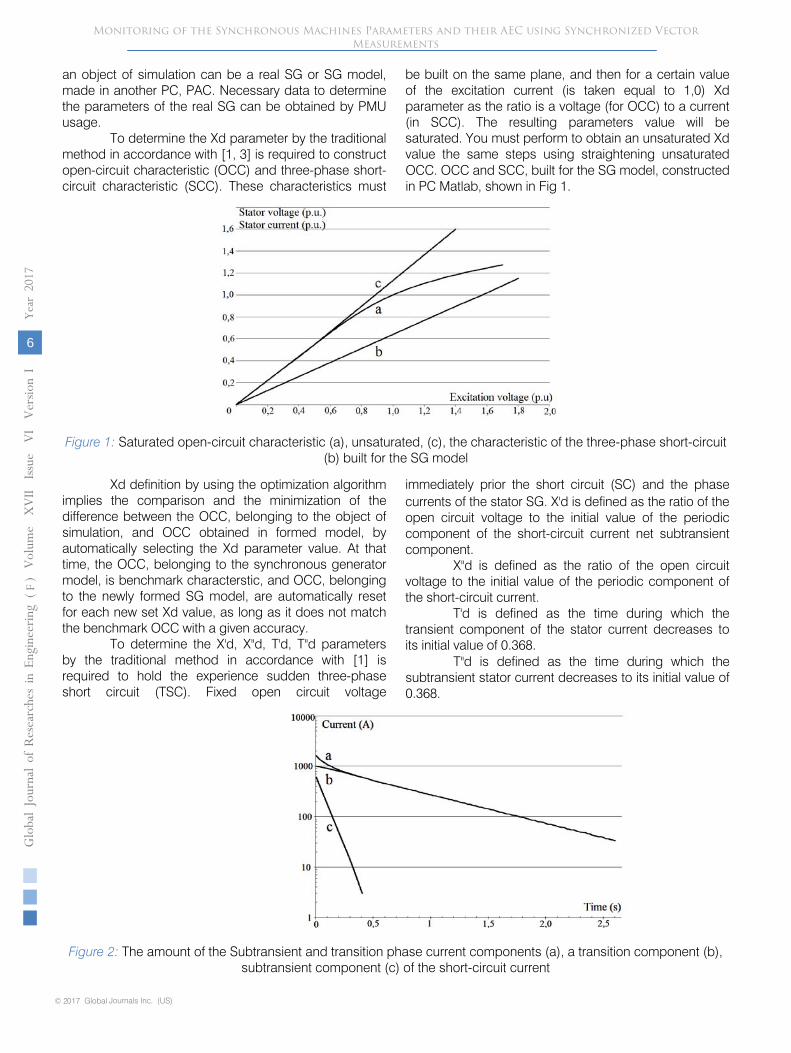
To determine the Xd parameter by the traditional method in accordance with [1, 3] is required to construct open-circuit characteristic (OCC) and three-phase short-circuit characteristic (SCC). These characteristics must
be built on the same plane, and then for a certain value of the excitation current (is taken equal to 1,0)
Xd parameter as the ratio is a voltage (for OCC) to a current (in SCC). The resulting parameters value will be saturated. You must perform to obtain an unsaturated Xd value the same steps using straightening unsaturated OCC. OCC and SCC, built for the SG model, constructed in PC Matlab, shown in Fig 1.
Figure 1:
Saturated open-circuit characteristic (a), unsaturated, (c), the characteristic of the three-phase short-circuit (b) built for the SG model
Xd definition by using the optimization algorithm implies the comparison and the minimization of the difference between the OCC, belonging to the object of simulation, and OCC obtained in formed model, by automatically selecting the
Xd parameter value. At that time, the OCC, belonging to the synchronous generator model, is benchmark characterstic, and OCC, belonging to the newly formed SG model, are automatically reset for each new set Xd value, as long as it does not match the benchmark OCC with a given accuracy.
To determine the X'd, X''d, T'd, T''d parameters by the traditional method in accordance with [1] is required to hold the experience sudden three-phase short circuit (TSC). Fixed open circuit voltage
immediately prior the short circuit (SC) and the phase currents of the stator SG. X'd is defined as the ratio of the open circuit voltage to the initial value of the periodic component of the short-circuit current net subtransient component.
X''d is defined as the ratio of the open circuit voltage to the initial value of the periodic component of the short-circuit current.
T'd is defined as the time during which the transient component of the stator current decreases to its initial value of 0.368.
T''d is defined as the time during which the subtransient stator current decreases to its initial value of 0.368.
© 2017 Global Journals Inc. (US)
Globa
l Jo
urna
l of
Resea
rche
s in E
nginee
ring
(
)Volum
e X
VII
Issu
e V
I V
ersion
I
6
Year
2017
FMonitoring of the Synchronous Machines Parameters and their AEC using Synchronized Vector
Measurements
Figure 2: The amount of the Subtransient and transition phase current components (a), a transition component (b), subtransient component (c) of the short-circuit current
To determine the X'd, X''d, T'd, T''d parameters by using optimization algorithms an optimization function, whose arguments are all required to parameters, is formed. On the SG model the experience sudden TSC is held and an oscillogram of phase stator current is fixed. From fixed oscillograms stands out periodic component of the current is defined as the half-algebraic ordinates of the upper and lower envelopes amplitude (shown in Fig. 2). After that the difference between the resulting curve and standart is minimized.
III.
DETERMINATION OF RS,
TA, X2
The Rs and Ta parameters should be determined from the experience of a sudden three-phase short circuit on the attenuation of the periodic component of the current in the excitation circuit, by the traditional method in accordance with [1]. For this the oscillogram of the excitation current is fixed at the shorted SG phase stator winding, which works in an idling.
From the fixed oscillogram, the periodic current component stands out and is plotted in semi-logarithmic coordinates.
Value of the time constant of the aperiodic stator current component Ta is defined as the time during which a periodic component of the current drive circuit decreased to its initial value of 0.368.
Rs = 0.8∙X2
/ (ωc∙Ta) (1)
Where X2
is an unsaturated parameter and can be determined by the equation [2]:
X2
= 1.1∙X’’d (2)
The approach to the determination of the Rs and Ta parameters by using optimization algorithms is similar to the one, which was used to determine the X'd, T'd parameters.
Optimization function, whose argument is the desired parameter Rs, is formed. On the SG model the experience sudden TSC is held. From a fixed
excitation current oscillogram the periodic component stands out. After that the difference between the resulting curve and benchmark is minimized.
The subsequent determination of the Ta time constant is produced by the equation (1).
At the same time X2
is defined by (2), wherein the subtransient inductive reactance X''d has already been defined by the optimization method. It should be noted, that all data about necessary electrical quantities can be obtained by PMU usage.
IV.
DETERMINATION OF t’d0
For the determination of the transient time constant along a longitudinal d-axis at the open stator winding by the traditional method in accordance with [1], a voltage recovery method can be used.
The difference between the steady-state value voltage and recovery voltage U ( -U, defined by their amplitudes, is plotted in semi-logarithmic coordinates. Determination of the T'd0 parameter by the voltage recovery method consists in determining time during which a transient voltage component ΔU' decreases to its initial value of 0.368.
The procedure for determining
T'd0 parameter by the optimization algorithms similar to the procedure, which was performed in determining Xd parameter. At the same time is held the voltage recovery experience on the SG model and the stator voltage recovering oscillogram is also fixed, then from fixed oscillogram stands out the envelope and the difference between the benchmark curve and the obtained on the SG model is minimized.
© 2017 Global Journals Inc. (US)
Globa
l J o
urna
l of
Resea
rche
s in E
nginee
ring
(
)Volum
e X
VII
Issu
e V
I V
ersion
I
7
Year
2017
F
Monitoring of the Synchronous Machines Parameters and their AEC using Synchronized Vector Measurements
V. DETERMINATION OF SG STATOR WINDING
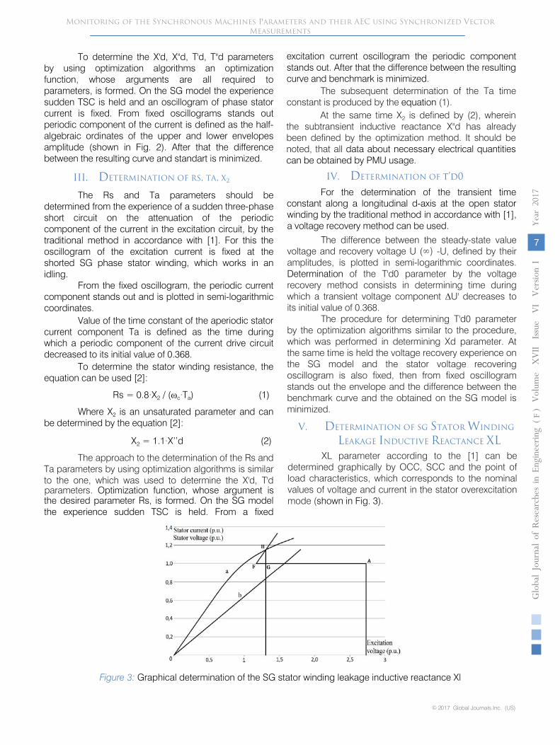
LEAKAGE INDUCTIVE REACTANCE XLXL parameter according to the [1] can be
determined graphically by OCC, SCC and the point of load characteristics, which corresponds to the nominal values of voltage and current in the stator overexcitation mode (shown in Fig. 3).
Figure 3: Graphical determination of the SG stator winding leakage inductive reactance Xl
To determine the stator winding resistance, the equation can be used [2]:
∞)
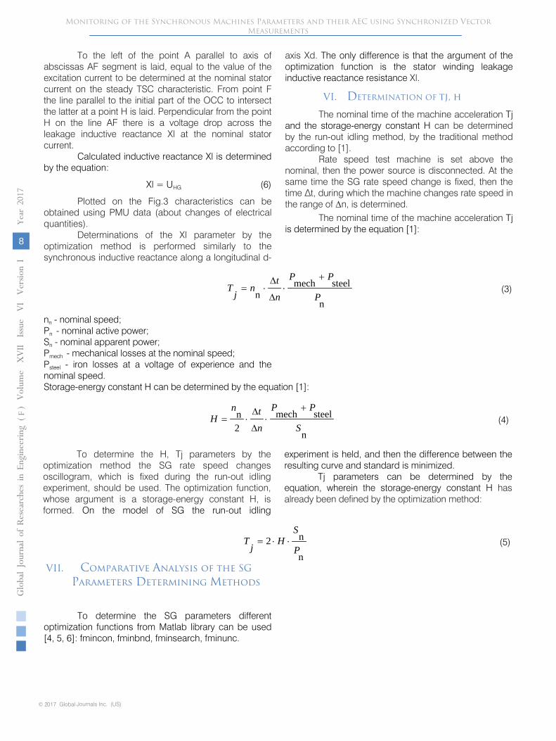
To the left of the point A parallel to axis of abscissas AF segment is laid, equal to the value of the excitation current to be determined at the nominal stator current on the steady TSC characteristic.
From point F the line parallel to the initial part of the OCC to intersect the latter at a point H is laid. Perpendicular from the point H on the line AF there is a voltage drop across the leakage inductive reactance Xl at the nominal stator current.
Calculated inductive reactance Xl is determined by the equation:
Xl = UHG (6)
Plotted on the Fig.3 characteristics can be obtained using PMU data (about changes of electrical quantities).
Determinations of the Xl parameter by the optimization method is performed similarly to
the synchronous inductive reactance along a longitudinal d-
axis Xd. The only difference is that the argument of the optimization function is the stator winding leakage inductive reactance
resistance Xl.
VI.
DETERMINATION OF tj, h
The nominal time of the machine acceleration Tj and the storage-energy constant H can be determined by the run-out idling method, by the traditional method according to [1].
Rate speed test machine is set above the nominal, then the power source is disconnected. At the same time the SG rate speed change is fixed, then the time ∆t, during which the machine changes rate speed in the range of Δn, is determined.
n
steelmechn P
PP
n
tn
jT
+⋅
∆
∆⋅= (3)
nn - nominal speed;
Pn - nominal active power; Sn - nominal apparent power;
Pmech - mechanical losses at the nominal speed;
Psteel - iron losses at a voltage of experience and the nominal speed.
Storage-energy constant H can be determined by the equation [1]:
© 2017 Global Journals Inc. (US)
Globa
l Jo
urna
l of
Resea
rche
s in E
nginee
ring
(
)Volum
e X
VII
Issu
e V
I V
ersion
I
8
Year
2017
FMonitoring of the Synchronous Machines Parameters and their AEC using Synchronized Vector
Measurements
n
steelmech2n
S
PP
n
tnH
+⋅
∆
∆⋅= (4)
To determine the H, Tj parameters by the optimization method the SG rate speed changes oscillogram, which is fixed during the run-out idling experiment, should be used. The optimization function, whose argument is a storage-energy constant H, is formed. On the model of SG the run-out idling
experiment is held, and then the difference between the resulting curve and standard is minimized.
Tj parameters can be determined by the equation, wherein the storage-energy constant H has already been defined by the optimization method:
n
n2P
SH
jT ⋅⋅= (5)
To determine the SG parameters different optimization functions from Matlab library can be used [4, 5, 6]: fmincon, fminbnd, fminsearch, fminunc.
The nominal time of the machine acceleration Tj is determined by the equation [1]:
VII. Comparative Analysis of the SGParameters Determining Methods
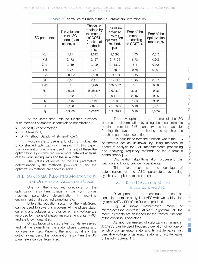
Table 1:
The Values of Errors of
the Sg Parameters Determination
SG parameter
The value set in the SG
model (data sheet), p.u.
The value obtained by the method
of GOST (traditional method),
p.u.
The value obtained
by the optimiza
tion
method, p.u.
Error of the method
according to GOST, %
Error of the optimization method, %
Xd 1,71
1,692
1,7098
1,05
0,012
X’d
0,172
0,157
0,17199
8,72
0,006
X’’d
0,119
0,109
0,11899
8,4
0,008
T’d
0,77
0,764
0,76998
0,78
0,003
T’’d
0,0962
0,108
0,96104
12,27
0,1
Xl 0,18
0,15
0,179981
16,67
0,011
T’d0
1 0,999
0,993437
0,1
0,66
Rs 0,0028
0,001897
0,002801
32,31
0,08
Ta
0,132
0,161
0,119
21,97
9,85
X2
0,145
0,1199
0,1309
17,3
9,72
H 2,136
2,0259
2,136035
5,16
0,0016
Tj
5,3406
5,06475
5,340875
5,16
0,0052
At the same time fminunc function provides such methods of smooth unconstrained optimization:
•
Steepest Descent method;
•
BFGS-method;
•
DFP-method (Davidon–Fletcher–Powell).
Most simple to use is a function of multivariate unconstrained optimization - fminsearch. In this paper, this optimization function is used. The rest of these the optimization algorithms require a more detailed analysis of their work, setting limits and the initial data.
The values of errors of the SG parameters determination by the methods, provided [1] and the optimization method, are shown in Table 1.
One of the important directions of the optimization algorithms usage is
the synchronous
© 2017 Global Journals Inc. (US)
Globa
l J o
urna
l of
Resea
rche
s in E
nginee
ring
(
)Volum
e X
VII
Issu
e V
I V
ersion
I
9
Year
2017
F
Monitoring of the Synchronous Machines Parameters and their AEC using Synchronized Vector Measurements
machine parameters determination in real-time environment or at specified sampling rate.
Differential equation system of the Park-Gorev can be used to solve this problem. All the phase stator currents and voltages and rotor current and voltage are recorded by means of phasor measurement units (PMU) and are known quantities.
On excitation winding the test signals are served and, at the same time, the stator phase currents and voltages are fixed. Knowing the input signal and the output signal using the optimization algorithms the SG parameters can be determined.
The development of the theme of the SG parameters determination by using the measurements obtained from the PMU can serve as the basis for forming the system of monitoring the synchronous machine parameters condition.
It is possible to form the function, where the AEC parameters act as unknown, by using methods of spectrum analysis for PMU measurements processing and analyzing frequency methods of the automatic control theory [16].
Optimization algorithms allow processing this function and finding unknown coefficients.
This article deals with the technique of determination of the AEC parameters by using synchronized pharos measurements.
IX. BRIEF DESCRIPTION OF THE
INVESTIGATIONAL AEC Development of the technique is based on
controller operation analysis of AEC with two stabilization systems (ARV-2SS) of the Russian production.
Fig. 4 shows mathematical model of microprocessor controller ARV-2S algorithm, all the model elements are described by the transfer functions of the continuous operator s.
As input parameters of stabilization channels in ARV-2SS can be used frequency deviation of voltage of synchronous generator stator and its first derivative, first derivative voltage of generator stator and first derivative of the rotor current [17].
VIII. SG AND AEC PARAMETERS MONITORING BY
THE OPTIMIZATION ALGORITHMS USAGE
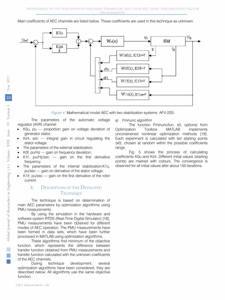
Figure 4:
Мathematical model AEC with two stabilization systems AFV-2SS
The parameters of the automatic voltage regulator (AVR) channel:
•
K0u, pu — proportion gain on voltage deviation of generator stator;
•
Kint, sec — integral gain in circuit regulating the stator voltage.
•
The parameters of the external stabilization:
•
K0f, pu/Hz — gain on frequency deviation;
•
K1f, pu/Hz/sec — gain on the first derivative frequency.
•
The parameters of the internal stabilization:K1u, pu/sec — gain on derivative of the stator
voltage;
•
K1if, pu/sec — gain on the first derivative of the rotor current.
The technique is based on determination of main AEC parameters by optimization algorithms using PMU measurements.
By using the simulation in the hardware and software system RTDS (Real-Time Digital Simulator) [18], PMU measurements have been obtained for different modes of AEC operation. The PMU measurements have
© 2017 Global Journals Inc. (US)
Globa
l Jo
urna
l of
Resea
rche
s in E
nginee
ring
(
)Volum
e X
VII
Issu
e V
I V
ersion
I
10
Year
2017
FMonitoring of the Synchronous Machines Parameters and their AEC using Synchronized Vector
Measurements
been formed in data sets, which have been further processed in MATLAB using optimization algorithms.
These algorithms find minimum of the objective function, which represents the difference between transfer function obtained from PMU measurements and transfer function calculated with the unknown coefficients of the AEC channels.
During technique development, several optimization algorithms have been considered, they are described below. All algorithms use the same objective function.
a) Fminunc algorithmThe function Fminunc(fun, x0, options) from
Optimization Toolbox MATLAB implements unconstrained nonlinear optimization methods [19]. Each experiment is calculated with ten starting points (x0), chosen at random within the possible coefficients range.
Fig. 5 shows the process of calculating coefficients K0u and Kint. Different initial values (starting points) are marked with colours. The convergence is observed for all initial values after about 150 iterations.
Main coefficients of AEC channels are listed below. These coefficients are used in this technique as unknown.
X. DESCRIPTION OF tHE DEVELOPED
TECHNIQUE
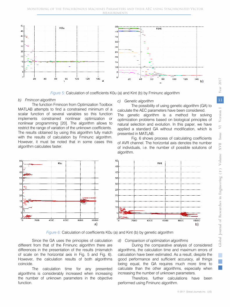
Figure 5:
Calculation of coefficients K0u (a) and Kint (b) by Fminunc algorithm
b)
Fmincon algorithm
The function Fmincon from Optimization Toolbox MATLAB attempts to find a constrained minimum of a scalar function of several variables so this function implements constrained nonlinear optimization or nonlinear programming [20]. The algorithm allows to restrict the range of variation of the unknown coefficients.
The results obtained by using this algorithm fully match with the results of calculation by Fminunc algorithm. However, it must be noted that in some cases this algorithm calculates faster.
c)
Genetic algorithm
The possibility of using genetic algorithm (GA) to calculate the AEC parameters have been considered.
The genetic algorithm is a method for solving optimization problems based on biological principles of natural selection and evolution. In this paper, we have applied a standard GA without modification, which is presented in MATLAB.
Fig. 6 shows process of calculating coefficients of AVR channel. The horizontal axis denotes the number of individuals, i.e. the number of possible solutions of algorithm.
© 2017 Global Journals Inc. (US)
Globa
l J o
urna
l of
Resea
rche
s in E
nginee
ring
(
)Volum
e X
VII
Issu
e V
I V
ersion
I
11
Year
2017
F
Monitoring of the Synchronous Machines Parameters and their AEC using Synchronized Vector Measurements
Figure 6: Calculation of coefficients K0u (a) and Kint (b) by genetic algorithm
Since the GA uses the principles of calculation different from that of the Fminunc algorithm there are differences in the presentation of the results (mismatch of scale on the horizontal axis in Fig. 5 and Fig. 6). However, the calculation results of both algorithms coincide.
The calculation time for any presented algorithms is considerably increased when increasing the number of unknown parameters in the objective function.
d) Comparison of optimization algorithmsDuring the comparative analysis of considered
algorithms, the calculation time and maximum errors of calculation have been estimated. As a result, despite the good performance and sufficient accuracy, all things being equal, the GA requires much more time to calculate than the other algorithms, especially when increasing the number of unknown parameters.
Therefore, further calculations have been performed using Fminunc algorithm.
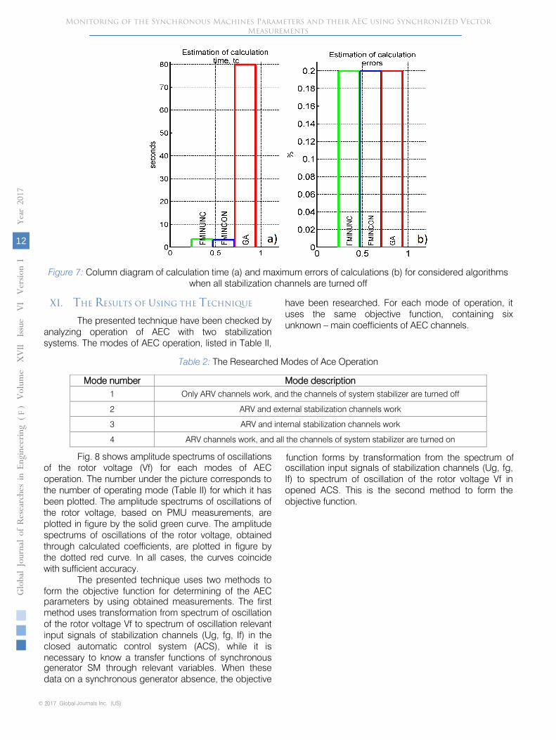
Figure 7:
Column diagram of calculation time (a) and maximum errors of calculations (b) for considered algorithms when all stabilization channels are turned off
© 2017 Global Journals Inc. (US)
Globa
l Jo
urna
l of
Resea
rche
s in E
nginee
ring
(
)Volum
e X
VII
Issu
e V
I V
ersion
I
12
Year
2017
FMonitoring of the Synchronous Machines Parameters and their AEC using Synchronized Vector
Measurements
The presented technique have been checked by analyzing operation of AEC with two stabilization systems. The modes of AEC operation, listed in Table II,
have been researched. For each mode of operation, it uses the same objective function, containing six unknown – main coefficients of AEC channels.
Table 2: The Researched Modes of Ace Operation
Mode number Mode description1 Only ARV channels work, and the channels of system stabilizer are turned off
2 ARV and external stabilization channels work
3 ARV and internal stabilization channels work
4 ARV channels work, and all the channels of system stabilizer are turned on
Fig. 8 shows amplitude spectrums of oscillations of the rotor voltage (Vf) for each modes of AEC operation. The number under the picture corresponds to the number of operating mode (Table II) for which it has been plotted. The amplitude spectrums of oscillations of the rotor voltage, based on PMU measurements, are plotted in figure by the solid green curve. The amplitude spectrums of oscillations of the rotor voltage, obtained through calculated coefficients, are plotted in figure by the dotted red curve. In all cases, the curves coincide with sufficient accuracy.
The presented technique uses two methods to form the objective function for determining of the AEC parameters by using obtained measurements. The first method uses transformation from spectrum of oscillation of the rotor voltage Vf to spectrum of oscillation relevant input signals of stabilization channels (Ug, fg, If) in the closed automatic control system (ACS), while it is necessary to know a transfer functions of synchronous generator SM through relevant variables. When these data on a synchronous generator absence, the objective
function forms by transformation from the spectrum of oscillation input signals of stabilization channels (Ug, fg, If) to spectrum of oscillation of the rotor voltage Vf in opened ACS. This is the second method to form the objective function.
XI. THE RESULTS OF USING THE TECHNIQUE
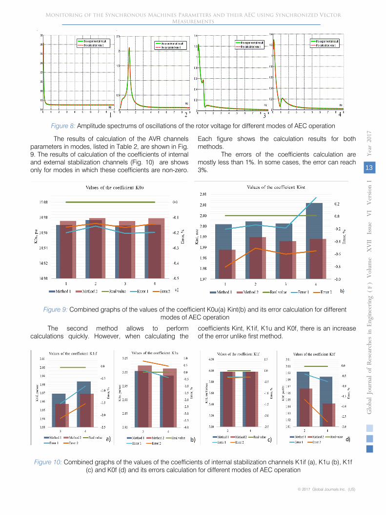
Figure 8:
Amplitude spectrums of oscillations of the rotor voltage for different modes of AEC operation
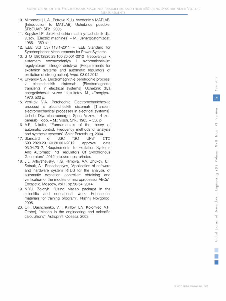
The results of calculation of the
AVR channels parameters in modes, listed in Table 2, are shown in Fig. 9. The results of calculation of the coefficients of internal and external stabilization channels (Fig. 10) are shows only for modes in which these coefficients are non-zero.
Each figure shows the calculation results for both methods.
The errors of the coefficients calculation are mostly less than 1%. In some cases, the error can reach 3%.
© 2017 Global Journals Inc. (US)
Globa
l J o
urna
l of
Resea
rche
s in E
nginee
ring
(
)Volum
e X
VII
Issu
e V
I V
ersion
I
13
Year
2017
F
Monitoring of the Synchronous Machines Parameters and their AEC using Synchronized Vector Measurements
Figure 9: Combined graphs of the values of the coefficient K0u(a) Kint(b) and its error calculation for different modes of AEC operation
The second method allows to perform calculations quickly. However, when calculating the
coefficients Kint, K1if, K1u and K0f, there is an increase of the error unlike first method.
Figure 10: Combined graphs of the values of the coefficients of internal stabilization channels K1if (a), K1u (b), K1f (c) and K0f (d) and its errors calculation for different modes of AEC operation

Also the presented technique has been checked, when in the circuit there is a noise of different power level. For these experiments, we have used ower system model in RTDS.
As previously, the calculations have been carried out in two methods using the Fminunc algorithm with six unknown parameters in objective function. The technique is fully confirmed.
XII.
CONCLUSION
In this paper several synchronous generator parameters were determined; the other SG parameters can also be determined by using the optimization algorithms.
These results confirm the effectiveness of the proposed alternative methodology for the SM model parameters determining. The error in the parameters determining of this method is much lower than with classical methods and almost absent. The error in determining Ta and X2 parameters involves the usage of the approximate calculation equations. On further research this error can be reduced. Method using the optimization algorithms can also be used in combination with traditional methods.
The developed method can also be used to verify the existing SM model, taking into account the fact that the needed oscillograms and characteristics of simulated machine exist.
The proposed method is universal and can be used in the different PCs and PACs. Since the parameters are selected by iterations directly in the simulation environment, the method automatically takes into account the peculiarities of simulation SG in any given PCs or PACs.
Developing the direction of application of optimization algorithms to determine the SM parameters can achieve even more accurate forming the SM model, which will increase the quality of carried by them
© 2017 Global Journals Inc. (US)
Globa
l Jo
urna
l of
Resea
rche
s in E
nginee
ring
(
)Volum
e X
VII
Issu
e V
I V
ersion
I
14
Year
2017
FMonitoring of the Synchronous Machines Parameters and their AEC using Synchronized Vector
Measurements
researches and also have a positive impact on the reliability of the results.
Another actual direction of the optimization algorithms usage is the synchronous generator parameters monitoring in real-time environment using the PMU.
The proposed technique allows to use PMU measurements to determine the AEC parameters by optimization algorithms. The technique has been checked on AEC with two stabilization systems in different modes of AEC operation.
Also in the study the comparative analysis of applying different optimization algorithms has been performed. As a result, despite the good performance and sufficient accuracy the GA requires much more time to calculate than the other algorithms, especially when increasing the number of unknown parameters.
The developed technique determines AEC parameters with sufficient accuracy by using PMU
measurements, including when in the circuit there is a noise of different power level.
Thus, the technique allows to extend the field of PMU application, and with further development, will allow to monitor AEC and calculate its parameters in real time.
References Références Referencias
1. GOST 10169-77 Mashiny jelektricheskie trehfaznye sinhronnye. Metody ispytanij. [Electric three-phase synchronous machine. Test methods] – Instead of GOST 10169-68; vved. 1978-01-01. - Moscow: Izd-vo standartov, 1984. – 85 p.
2. Kuznecov Y.P. Metody raschetov rezhimov raboty electrooborudovaniya electricheskih stancij i podstancij [The calculation methods of operating modes of electric power stations and substations].
3. Vol’dek A.I. Electricheskie mashiny. [Electric machines] The textbook for university students. – 3 edition., revised – L.: Energy Publ., 1978. – 832 p.
4. Zolotyh N.Y. Ispol’zovanie paketa Matlab v nauchnoi i uchebnoi rabote. [Use of MATLAB in scientific and educational work]. Uchebno-metodicheskie materialy po programme povisheniya kvalifikacii “Informatsionnie tehnologii i komp’youternay matematika” [Educational materials for the training program "Information technology and computer mathematics"]. Nizhny Novgorod, 2006.
5. Daschenko A.F., Kirillov V.H., Kolomiec L.V., Orobei V.F. MATLAB v inzhenernyh i nauchnyh raschetah [Use of MATLAB in the engineering and scientific calculations]. Odessa, Astroprint Publ. 2003.
6. Chernyh I.V. Modelirovanie elektrotehnicheskih ustrojstv v MATLAB, SimPowerSystems i Simulink [Simulation of electrotechnical devices in Matlab, SimPowerSystems and Simulink]. M.: DMK Press, SPB: Piter, 2008. 288 p.
7. Kovalenko A.I., Klimova T.G. Definitions and update of synchronous machine model parameters using optimization algorithms // Sbornik materialov ХХХVIII sessii Vserosiiskogo nauchnogo seminara po tematike «Diagnostika energooborudovaniya». [Diagnostic of power equipment] – Novocherkassk, 2016. P. 31-41
8. Kovalenko A.I., Klimova T.G. Application of optimization algorithms for definitions and update of synchronous machine model parameters // Materialy VII Mezhdunarodnoi molodezhnoi nauchno-tehnichskoi konferencii «Electroenergetica glazami molodezhi - 2016» [Power engineering through the eyes of the youth – 2016]. – Kazan, 2016. P. 244-247
9. Ob’em i normy ispytanij jelektrooborudovanija. [Scope and standards of electrical equipment testing] RD 34.45-51.300-97. Shestoe izdanie. Utv. RAO «EJeS Rossii» 08.05.1997. M., Izdatel'stvo NC JeNAS, 2004
10.
Mironovskij L.A., Petrova K.Ju. Vvedenie v MATLAB. [Introduction to MATLAB] Uchebnoe posobie. SPbGUAP. SPb., 2005
11.
Kopylov I.P. Jelektricheskie mashiny: Uchebnik dlja vuzov. [Electric machines] – M.: Jenergoatomizdat, 1986. – 360 s.: il.
12.
IEEE Std C37.118.1-2011 – IEEE Standard for Synchrophasor Measurements for Power Systems.
13.
STO 59012820.29.160.20.001-2012 Trebovaniya k sistemam vozbuzhdeniya I avtomaticheskim regulyatoram silnogo deistviya [Requirements for excitation systems and automatic regulators of excitation of strong action]. Vved. 03.04.2012.
14.
Ul’yanov S.A. Electromagnitnie perehodnie processi v electricheskih sistemah [Electromagnetic transients in electrical systems]. Uchebnik dlya energeticheskih vuzov i fakultetov. M., «Energiya», 1970. 520 p.
15.
Venikov V.A. Perehodnie Electromehanicheskie processi в
electricheskih sistemah [Transient electromechanical processes in electrical systems]: Ucheb. Dlya electroenerget. Spec. Vuzov. – 4 izd., pererab. i dop. – М.: Vissh. Shk., 1985. – 536 p.
16.
A.E. Nikulin, “Fundamentals of the theory of automatic control. Frequency methods of analysis and synthesis systems”, Saint-Petersburg, 2004.
17.
Standard of JSC “SO UPS” СТО
59012820.29.160.20.001-2012, approval date 03.04.2012, “Requirements To Excitation Systems And Automatic Pid Regulators Of Synchronous Generators”, 2012 http://so-ups.ru/index.
18.
J.L. Artsyshevsky, T.G. Klimova, A.V. Zhukov, E.I. Satsuk, A.I. Rasscheplyev, “Application of software and hardware system RTDS for the analysis of automatic excitation controller: obtaining and verification of the models of microprocessor AECs”, Energetic, Moscow, vol.1, pp.50-54, 2014.
© 2017 Global Journals Inc. (US)
Globa
l J o
urna
l of
Resea
rche
s in E
nginee
ring
(
)Volum
e X
VII
Issu
e V
I V
ersion
I
15
Year
2017
F
Monitoring of the Synchronous Machines Parameters and their AEC using Synchronized Vector Measurements
19. N.YU. Zolotyh, “Using Matlab package in the scientific and educational work. Educational materials for training program”, Nizhnij Novgorod, 2006.
20. O.F. Dashchenko, V.H. Kirillov, L.V. Kolomiec, V.F. Orobej, “Matlab in the engineering and scientific calculations”, Astroprint, Odessa, 2003.

© 2017 Global Journals Inc. (US)
Globa
l Jo
urna
l of
Resea
rche
s in E
nginee
ring
(
)Volum
e X
VII
Issu
e V
I V
ersion
I
16
Year
2017
FMonitoring of the Synchronous Machines Parameters and their AEC using Synchronized Vector
Measurements
This page is intentionally left blank