monitoring and protecting plug and play retrofit solution ... · masterpact ur is a low voltage...
TRANSCRIPT
ABTED103158EN
35, rue Joseph MonierCS 30323F- 92506 Rueil Malmaison Cedex
RCS Nanterre 954 503 439Capital social 896 313 776 ewww.schneider-electric.com
Printed on ecological paper
01-2011
Schneider Electric Industries SASAs standards, specifications and designs change from time to time, please ask for confirmationof the information given in this publication.
AR
T56
289
© 2
010
Sch
neid
er E
lect
ric In
dust
ries
SA
S -
All
right
s re
serv
ed
Publishing: Schneider Electric Industries SASDesign - Layout: SEDOC Printing:
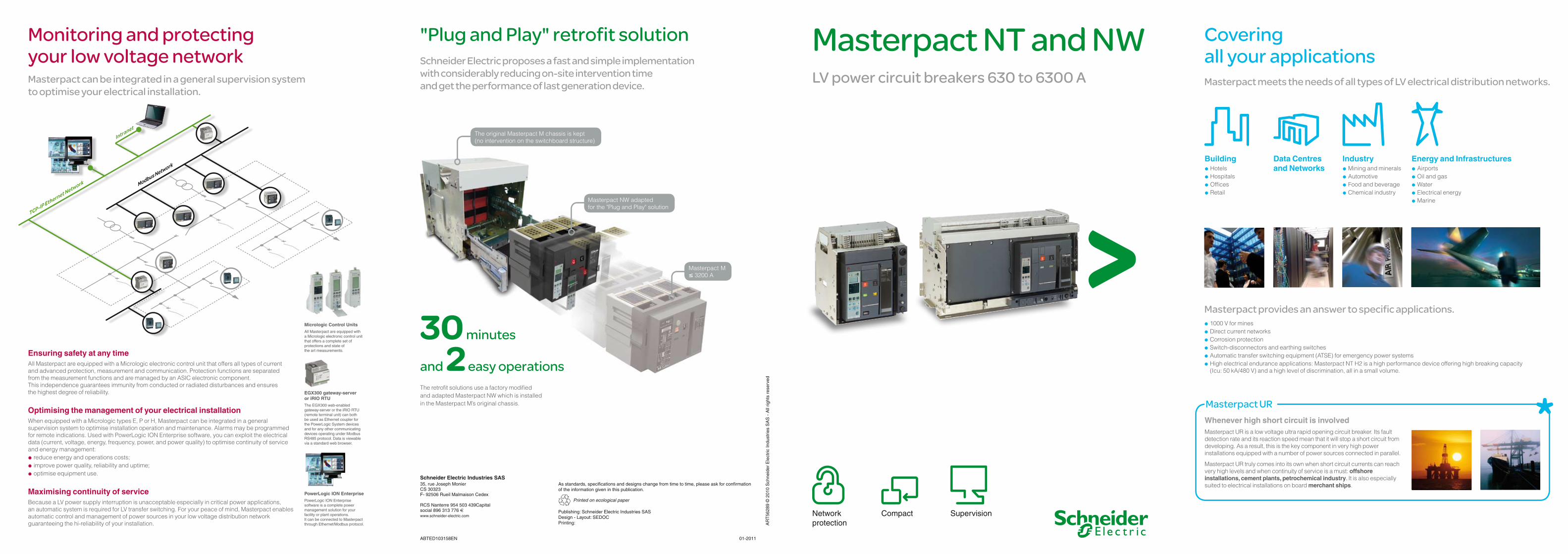
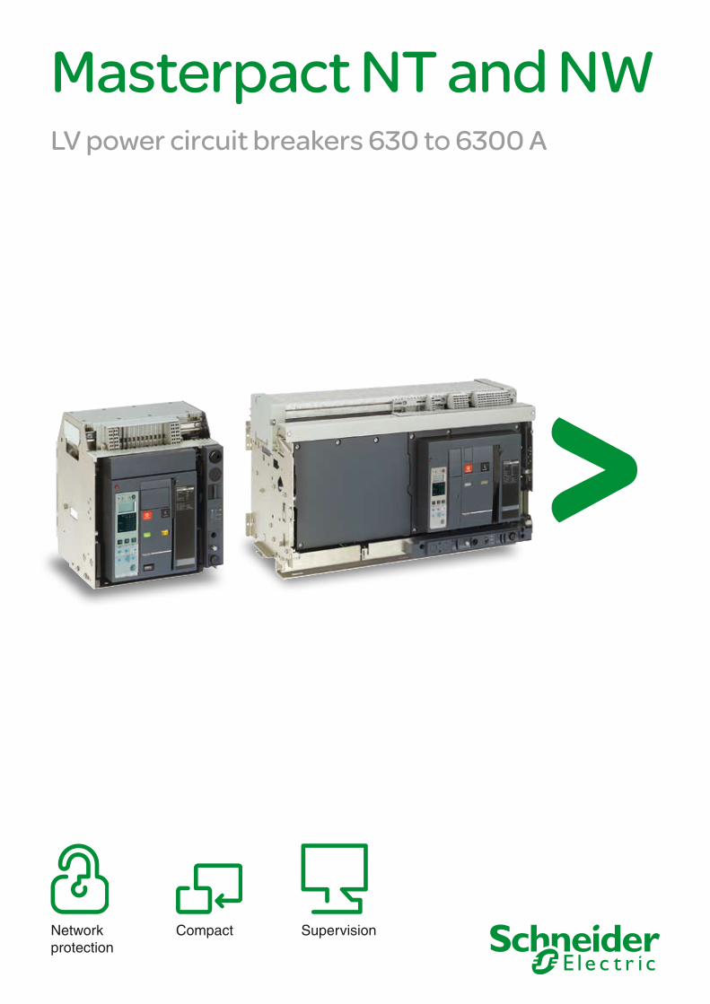
Masterpact NT and NWLV power circuit breakers 630 to 6300 A
Network protection
Compact Supervision
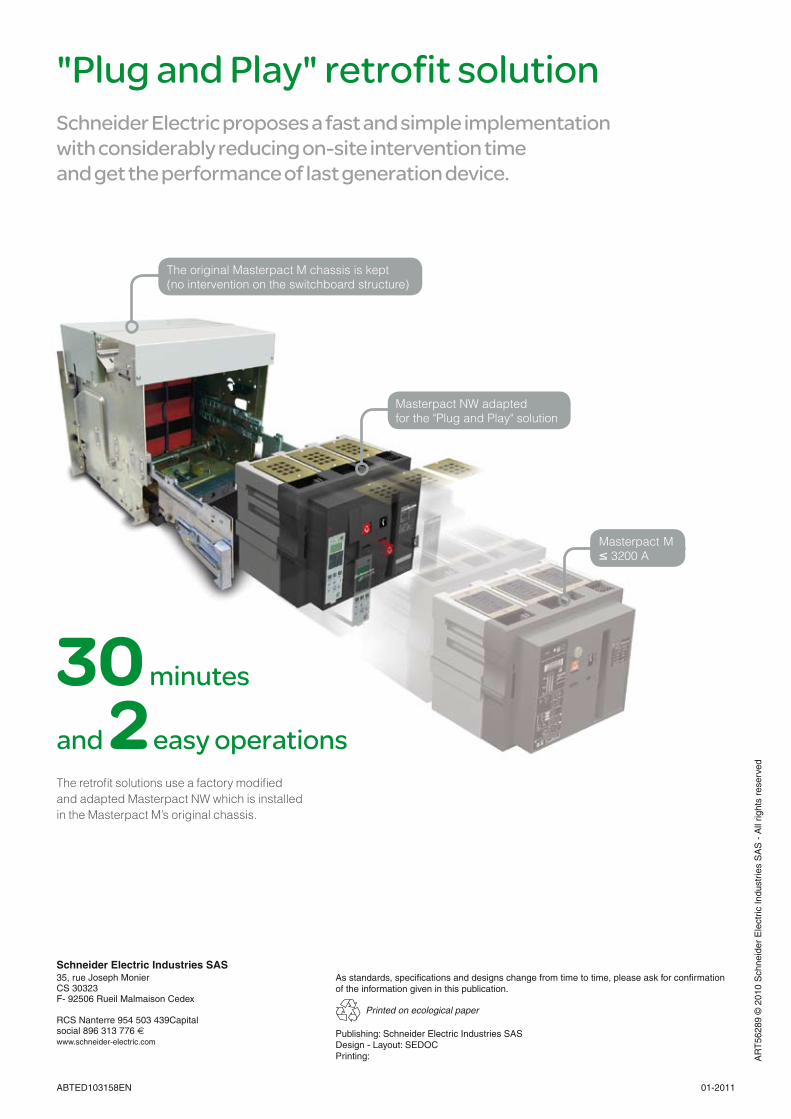
The original Masterpact M chassis is kept (no intervention on the switchboard structure)
Masterpact NW adapted for the "Plug and Play" solution
Masterpact M ≤ 3200 A
"Plug and Play" retrofit solutionSchneider Electric proposes a fast and simple implementation with considerably reducing on-site intervention time and get the performance of last generation device.
30 minutes
and 2 easy operationsThe retrofit solutions use a factory modified and adapted Masterpact NW which is installed in the Masterpact M’s original chassis.
Monitoring and protecting your low voltage network Masterpact can be integrated in a general supervision system to optimise your electrical installation.
Covering all your applications
Masterpact provides an answer to specific applications.1000 V for mines @Direct current networks @Corrosion protection @Switch-disconnectors and earthing switches @Automatic transfer switching equipment (ATSE) for emergency power systems @High electrical endurance applications: Masterpact NT H2 is a high performance device offering high breaking capacity @(Icu: 50 kA/480 V) and a high level of discrimination, all in a small volume.
Ensuring safety at any timeAll Masterpact are equipped with a Micrologic electronic control unit that offers all types of current and advanced protection, measurement and communication. Protection functions are separated from the measurement functions and are managed by an ASIC electronic component. This independence guarantees immunity from conducted or radiated disturbances and ensures the highest degree of reliability.
Optimising the management of your electrical installation When equipped with a Micrologic types E, P or H, Masterpact can be integrated in a general supervision system to optimise installation operation and maintenance. Alarms may be programmed for remote indications. Used with PowerLogic ION Enterprise software, you can exploit the electrical data (current, voltage, energy, frequency, power, and power quality) to optimise continuity of service and energy management:
reduce energy and operations costs; @improve power quality, reliability and uptime; @optimise equipment use. @
Maximising continuity of serviceBecause a LV power supply interruption is unacceptable especially in critical power applications, an automatic system is required for LV transfer switching. For your peace of mind, Masterpact enables automatic control and management of power sources in your low voltage distribution network guaranteeing the hi-reliability of your installation.
EGX300 gateway-server or iRIO RTUThe EGX300 web-enabled gateway-server or the iRIO RTU (remote terminal unit) can both be used as Ethernet coupler for the PowerLogic System devices and for any other communicating devices operating under Modbus RS485 protocol. Data is viewable via a standard web browser.
PowerLogic ION EnterprisePowerLogic ION Enterprise software is a complete power management solution for your facility or plant operations. It can be connected to Masterpact through Ethernet/Modbus protocol.
Masterpact meets the needs of all types of LV electrical distribution networks.
Whenever high short circuit is involvedMasterpact UR is a low voltage ultra rapid opening circuit breaker. Its fault detection rate and its reaction speed mean that it will stop a short circuit from developing. As a result, this is the key component in very high power installations equipped with a number of power sources connected in parallel.
Masterpact UR truly comes into its own when short circuit currents can reach very high levels and when continuity of service is a must: offshore installations, cement plants, petrochemical industry. It is also especially suited to electrical installations on board merchant ships.
Masterpact UR
BuildingHotels @Hospitals @Offices @Retail @
Data Centres and Networks
IndustryMining and minerals @Automotive @Food and beverage @Chemical industry @
Energy and InfrastructuresAirports @Oil and gas @Water @Electrical energy @ Marine @
Micrologic Control UnitsAll Masterpact are equipped with a Micrologic electronic control unit that offers a complete set of protections and state of the art measurements.
Modbus Network
TCP-IP Ethernet Network
Intranet

Monitoring and protecting your low voltage network Masterpact can be integrated in a general supervision system to optimise your electrical installation.
Ensuring safety at any timeAll Masterpact are equipped with a Micrologic electronic control unit that offers all types of current and advanced protection, measurement and communication. Protection functions are separated from the measurement functions and are managed by an ASIC electronic component. This independence guarantees immunity from conducted or radiated disturbances and ensures the highest degree of reliability.
Optimising the management of your electrical installation When equipped with a Micrologic types E, P or H, Masterpact can be integrated in a general supervision system to optimise installation operation and maintenance. Alarms may be programmed for remote indications. Used with PowerLogic ION Enterprise software, you can exploit the electrical data (current, voltage, energy, frequency, power, and power quality) to optimise continuity of service and energy management:
reduce energy and operations costs; @improve power quality, reliability and uptime; @optimise equipment use. @
Maximising continuity of serviceBecause a LV power supply interruption is unacceptable especially in critical power applications, an automatic system is required for LV transfer switching. For your peace of mind, Masterpact enables automatic control and management of power sources in your low voltage distribution network guaranteeing the hi-reliability of your installation.
EGX300 gateway-server or iRIO RTUThe EGX300 web-enabled gateway-server or the iRIO RTU (remote terminal unit) can both be used as Ethernet coupler for the PowerLogic System devices and for any other communicating devices operating under Modbus RS485 protocol. Data is viewable via a standard web browser.
PowerLogic ION EnterprisePowerLogic ION Enterprise software is a complete power management solution for your facility or plant operations. It can be connected to Masterpact through Ethernet/Modbus protocol.
Micrologic Control UnitsAll Masterpact are equipped with a Micrologic electronic control unit that offers a complete set of protections and state of the art measurements.
Modbus Network
TCP-IP Ethernet Network
Intranet
ABTED103158EN
35, rue Joseph MonierCS 30323F- 92506 Rueil Malmaison Cedex
RCS Nanterre 954 503 439Capital social 896 313 776 ewww.schneider-electric.com
Printed on ecological paper
01-2011
Schneider Electric Industries SASAs standards, specifications and designs change from time to time, please ask for confirmationof the information given in this publication.
AR
T56
289
© 2
010
Sch
neid
er E
lect
ric In
dust
ries
SA
S -
All
right
s re
serv
ed
Publishing: Schneider Electric Industries SASDesign - Layout: SEDOC Printing:
The original Masterpact M chassis is kept (no intervention on the switchboard structure)
Masterpact NW adapted for the "Plug and Play" solution
Masterpact M ≤ 3200 A
"Plug and Play" retrofit solutionSchneider Electric proposes a fast and simple implementation with considerably reducing on-site intervention time and get the performance of last generation device.
30 minutes
and 2 easy operationsThe retrofit solutions use a factory modified and adapted Masterpact NW which is installed in the Masterpact M’s original chassis.
Masterpact NT and NWLV power circuit breakers 630 to 6300 A
Network protection
Compact Supervision

Covering all your applications
Masterpact provides an answer to specific applications.1000 V for mines @Direct current networks @Corrosion protection @Switch-disconnectors and earthing switches @Automatic transfer switching equipment (ATSE) for emergency power systems @High electrical endurance applications: Masterpact NT H2 is a high performance device offering high breaking capacity @(Icu: 50 kA/480 V) and a high level of discrimination, all in a small volume.
Masterpact meets the needs of all types of LV electrical distribution networks.
Whenever high short circuit is involvedMasterpact UR is a low voltage ultra rapid opening circuit breaker. Its fault detection rate and its reaction speed mean that it will stop a short circuit from developing. As a result, this is the key component in very high power installations equipped with a number of power sources connected in parallel.
Masterpact UR truly comes into its own when short circuit currents can reach very high levels and when continuity of service is a must: offshore installations, cement plants, petrochemical industry. It is also especially suited to electrical installations on board merchant ships.
Masterpact UR
BuildingHotels @Hospitals @Offices @Retail @
Data Centres and Networks
IndustryMining and minerals @Automotive @Food and beverage @Chemical industry @
Energy and InfrastructuresAirports @Oil and gas @Water @Electrical energy @ Marine @

Circuit breakers and switch-disconnectorsNT06 to NT16
Circuit breakers and switch-disconnectorsNW08 to NW63
Common characteristicsNumber of poles 3/4Rated insulation voltage (V) Ui 1000Impulse withstand voltage (kV) Uimp 12Rated operational volt. (V AC 50/60 Hz) Ue 690Suitability for isolation IEC 60947-2 Degree of pollution IEC 60664-1 3
Sensor selectionSensor rating (A) 250 (1) 400 630 800 1000 1250 1600Ir threshold set. (A) 100
to 250160 to 400
250 to 630
320 to 800
400 to 1000
500 to 1250
640 to 1600
(1) For NT02 rating, please consult us.
Circuit breaker characteristics as per IEC 60947-2 NT06 NT08 NT10 NT12 NT16Rated current (A) In 40/50 °C (1) 630 800 1000 1250 1600Rating of 4th pole (A) 630 800 1000 1250 1600Sensor ratings (A) 400 to 630 400 to 800 400 to 1000 630 to 1250 800 to 1600Type of circuit breaker H1 H2 L1 (2) H1 H2
Ultimate breaking capacity (kA rms)V AC 50/60 Hz
Icu 220/415 V 42 50 150 42 50440 V 42 50 130 42 50525 V 42 42 100 42 42690 V 42 42 25 42 42
Rated service breaking capacity (kA rms) Ics % Icu 100% 100%Utilisation category B B A B BRated short-time withstand current (kA rms)V AC 50/60 Hz
Icw 0.5 s 42 36 10 42 361 s 42 36 - 42 363 s 24 20 - 24 20
Integrated instantaneous protection (kA peak ±10 %) - 90 10xIn (3) - 90Rated making capacity (kA peak)V AC 50/60 Hz
Icm 220/415 V 88 105 330 88 105440 V 88 105 286 88 105525 V 88 88 220 88 88690 V 88 88 52 88 88
Break time (ms) between tripping order and arc extinction 25 25 9 25 25Closing time (ms) < 50 < 50
Circuit breaker characteristics as per NEMA AB1Breaking capacity (kA)V AC 50/60 Hz
240 V 42 50 150 42 50480 V 42 50 100 42 50600 V 42 42 25 42 42
Switch-disconnector characteristics as per IEC 60947-3 and Annex AType of switch-disconnector HA HA
Rated making capacity (kA peak)AC23A/AC3 category - V AC 50/60 Hz
Icm 220 V 75 75440 V 75 75525/690 V 75 75
Rated short-time withstand current (kA rms)AC23A/AC3 category - V AC 50/60 Hz
Icw 0.5 s 36 361 s 36 363 s 20 20
Ultimate breaking capacity Icu (kA rms) with an external protection relayMaximum time delay: 350 ms
690 V 36 36
Mechanical and electrical durability as per IEC 60947-2/3 at In/IeService lifeC/O cycles x 1000
Mechanical without maintenance 12.5
Type of circuit breaker H1 H2 L1 H1 H2 L1 H1 H2 L1 H1 H2 H1 H2Rated current In (A) 630 800 1000 1250 1600
C/O cycles x 1000 Electrical without maintenance 440 V (4) 6 6 3 6 6 3 6 6 3 6 6 3 3IEC 60947-2 690 V 3 3 2 3 3 2 3 3 2 3 3 1 1Type of circuit breaker or switch-disconnector H1 / H2 / HARated operationnal current Ie (A) AC23A 630 800 1000 1250 1600
C/O cycles x 1000 Electrical without maintenance 440 V (4) 6 6 6 6 3IEC 60947-3 690V 3 3 3 3 1Type of circuit breaker or switch-disconnector H1 / H2 / HARated operationnal current Ie (A) AC3 (5) 500 630 800 1000 1000
Motor power (kW) 380/415 V ≤ 250 250 to 335 335 to 450 450 to 560 450 to 560440 V ≤ 300 300 to 400 400 to 500 500 to 630 500 to 630
C/O cycles x 1000 Electrical without maintenance 440 V (4) 6IEC 60947-3 Annex M/IEC 60947-4-1 690 V -
(1) 50 °C: rear vertical connected. Refer to temperature derating tables for other connection types. (2) See the current-limiting curves in the "additional characteristics" section. (3) SELLIM system. (4) Available for 480 V NEMA. (5) Suitable for motor control (direct-on-line starting).
Common characteristicsNumber of poles 3/4Rated insulation voltage (V) Ui 1000/1250Impulse withstand voltage (kV) Uimp 12Rated operational voltage (V AC 50/60 Hz) Ue 690/1150Suitability for isolation IEC 60947-2 Degree of pollution IEC 60664-1 4 (1000 V) / 3 (1250 V)
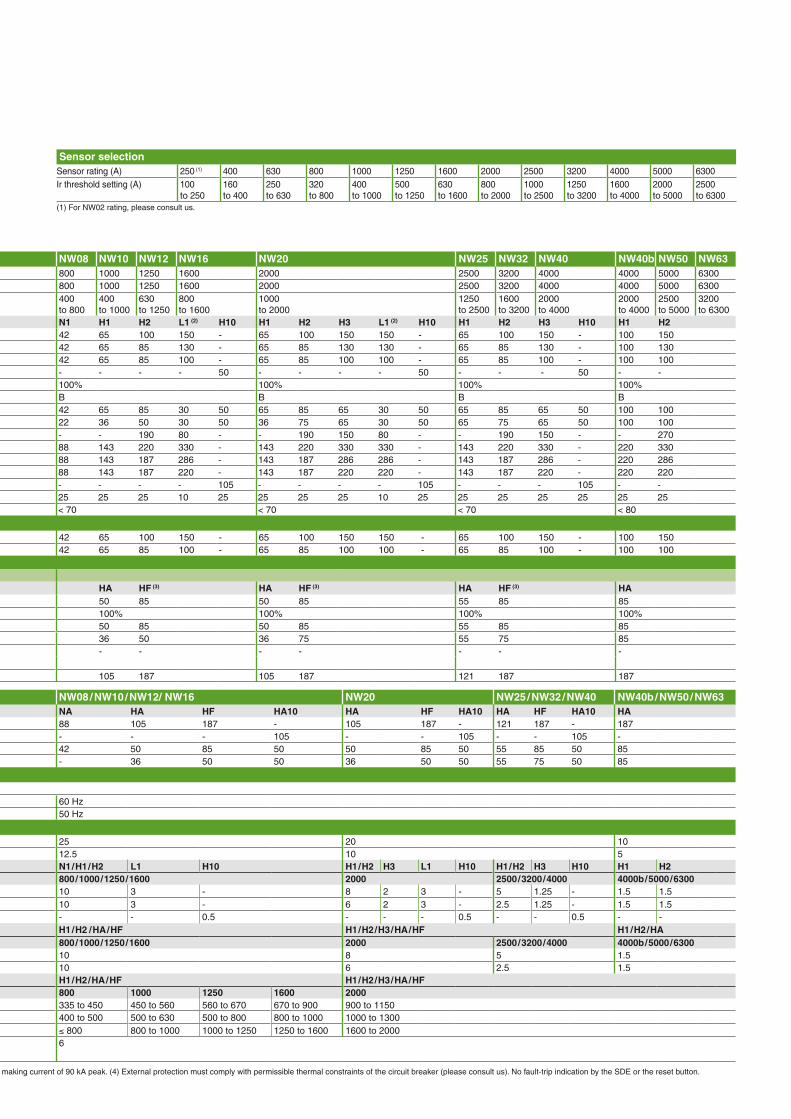
Sensor selectionSensor rating (A) 250 (1) 400 630 800 1000 1250 1600 2000 2500 3200 4000 5000 6300Ir threshold setting (A) 100
to 250160 to 400
250 to 630
320 to 800
400 to 1000
500 to 1250
630 to 1600
800 to 2000
1000 to 2500
1250 to 3200
1600 to 4000
2000 to 5000
2500 to 6300
(1) For NW02 rating, please consult us.
Circuit breaker characteristics as per IEC 60947-2 NW08 NW10 NW12 NW16 NW20 NW25 NW32 NW40 NW40b NW50 NW63Rated current (A) at 40 °C / 50 °C (1) 800 1000 1250 1600 2000 2500 3200 4000 4000 5000 6300Rating of 4th pole (A) 800 1000 1250 1600 2000 2500 3200 4000 4000 5000 6300Sensor ratings (A) 400
to 800400 to 1000
630 to 1250
800 to 1600
1000 to 2000
1250 to 2500
1600 to 3200
2000 to 4000
2000 to 4000
2500 to 5000
3200 to 6300
Type of circuit breaker N1 H1 H2 L1 (2) H10 H1 H2 H3 L1 (2) H10 H1 H2 H3 H10 H1 H2Ultimate breaking capacity (kA rms) Icu 220/415/440 V 42 65 100 150 - 65 100 150 150 - 65 100 150 - 100 150V AC 50/60 Hz 525 V 42 65 85 130 - 65 85 130 130 - 65 85 130 - 100 130
690 V 42 65 85 100 - 65 85 100 100 - 65 85 100 - 100 1001150 V - - - - 50 - - - - 50 - - - 50 - -
Rated service breaking capacity (kA rms) Ics % Icu 100% 100% 100% 100%Utilisation category B B B BRated short-time withstand current (kA rms)V AC 50/60 Hz
Icw 1 s 42 65 85 30 50 65 85 65 30 50 65 85 65 50 100 1003 s 22 36 50 30 50 36 75 65 30 50 65 75 65 50 100 100
Integrated instantaneous protection (kA peak ±10 %) - - 190 80 - - 190 150 80 - - 190 150 - - 270Rated making capacity (kA peak)V AC 50/60 Hz
Icm 220/415/440 V 88 143 220 330 - 143 220 330 330 - 143 220 330 - 220 330525 V 88 143 187 286 - 143 187 286 286 - 143 187 286 - 220 286690 V 88 143 187 220 - 143 187 220 220 - 143 187 220 - 220 2201150 V - - - - 105 - - - - 105 - - - 105 - -
Break time (ms) between tripping order and arc extinction 25 25 25 10 25 25 25 25 10 25 25 25 25 25 25 25Closing time (ms) < 70 < 70 < 70 < 80
Circuit breaker characteristics as per NEMA AB1Breaking capacity (kA) 240/480 V 42 65 100 150 - 65 100 150 150 - 65 100 150 - 100 150V AC 50/60 Hz 600 V 42 65 85 100 - 65 85 100 100 - 65 85 100 - 100 100
Unprotected circuit breaker characteristics:Tripping by shunt trip as per IEC 60947-2Type of circuit breaker HA HF (3) HA HF (3) HA HF (3) HA
Ultimate breaking capacity (kA rms) V AC 50/60 Hz Icu 220...690 V 50 85 50 85 55 85 85Rated service breaking capacity (kA rms) Ics % Icu 100% 100% 100% 100%Rated short-time withstand current (kA rms) Icw 1 s 50 85 50 85 55 85 85
3 s 36 50 36 75 55 75 85Overload and short-circuit protection with external protection relay:short-circuit protection, maximum delay: 350 ms(4)
- - - - - - -
Rated making capacity (kA peak) V AC 50/60 Hz Icm 220...690 V 105 187 105 187 121 187 187
(1) 50 °C: rear vertical connected. Refer to temperature derating tables for other connection types. (2) See the current-limiting curves in the "additional characteristics" section. (3) Equipped with a trip unit with a making current of 90 kA peak. (4) External protection must comply with permissible thermal constraints of the circuit breaker (please consult us). No fault-trip indication by the SDE or the reset button. (5) Available for 480 V NEMA. (6) Suitable for motor control (direct-on-line starting).
Concentrated know-how
More than
60 patents
86% of materials can be recycled at the end of product life.
Aiming at standardising electrical switchboards at a time when installations are increasingly complex, Masterpact provides an unequalled simplicity, both concerning choice and installation.
Compliance with environmental requirementsThe materials used for Masterpact are not potentially dangerous to the environment and are marked to facilitate sorting for recycling.
Production facilities are non-polluting in compliance with the ISO 14001 standard.
All standardsMasterpact is compliant with international standards IEC 60947-1 and 2, IEC 68230 for type 2 tropicalisation, UL489, ANSI/UL1066, CCC and GOST.
Optimised volumesMasterpact is the smallest power circuit breaker in the world, concentrating all the performances of a sophisticated power circuit breaker in compact dimensions. Masterpact thus optimises the installation and guarantees its operation in complete peace of mind.
Ease of installationMasterpact range has been designed to standardise switchboards and simplify installation:
single pole pitch for each physical size: @ 115/230 mm for NW, 70 mm for NT;incoming connection to top or bottom terminals: front or horizontal or vertical rear connections that can be modified @on-site without changing the depth;no derating up to 55 °C and 4000 A. @
Maximum securityThe arc chutes absorb the energy released during breaking, thus limiting the stresses exerted on the installation. They filter and cool the gases produced, reducing effects perceptible from the outside.
Masterpact NT Masterpact NW
Switch-disconnector characteristics as per IEC 60947-3 and Annex A NW08 / NW10 / NW12/ NW16 NW20 NW25 / NW32 / NW40 NW40b / NW50 / NW63Type of switch-disconnector NA HA HF HA10 HA HF HA10 HA HF HA10 HA
Rated making capacity (kA peak)AC23A/AC3 category - V AC 50/60 Hz
Icm 220...690 V 88 105 187 - 105 187 - 121 187 - 1871150 V - - - 105 - - 105 - - 105 -
Rated short-time withstand current (kA rms)AC23A/AC3 category - V AC 50/60 Hz
Icw 1 s 42 50 85 50 50 85 50 55 85 50 853 s - 36 50 50 36 50 50 55 75 50 85
Earthing switchLatching capacity (kA peak) 135Rating short time withstand (kA rms) Icw 1 s 60 Hz
3 s 50 Hz
Mechanical and electrical durability as per IEC 60947-2/3 at In/IeService life Mechanical with maintenance 25 20 10C/O cycles x 1000 without maintenance 12.5 10 5Type of circuit breaker N1 / H1 / H2 L1 H10 H1 / H2 H3 L1 H10 H1 / H2 H3 H10 H1 H2Rated current In (A) 800 / 1000 / 1250 / 1600 2000 2500 / 3200 / 4000 4000b / 5000 / 6300
C/O cycles x 1000 Electrical without maintenance 440 V (5) 10 3 - 8 2 3 - 5 1.25 - 1.5 1.5IEC 60947-2 690 V 10 3 - 6 2 3 - 2.5 1.25 - 1.5 1.5
1150 V - - 0.5 - - - 0.5 - - 0.5 - -Type of circuit breaker or switch-disconnector H1 / H2 / HA / HF H1 / H2 / H3 / HA / HF H1 / H2 / HARated operational current Ie (A) AC23A 800 / 1000 / 1250 / 1600 2000 2500 / 3200 / 4000 4000b / 5000 / 6300
C/O cycles x 1000 Electrical without maintenance 440 V (5) 10 8 5 1.5IEC 60947-3 690 V 10 6 2.5 1.5Type of circuit breaker or switch-disconnector H1 / H2 / HA / HF H1 / H2 / H3 / HA / HFRated operational current Ie (A) AC3 (6) 800 1000 1250 1600 2000
Motor power 380/415 V (kW) 335 to 450 450 to 560 560 to 670 670 to 900 900 to 1150440 V (5) (kW) 400 to 500 500 to 630 500 to 800 800 to 1000 1000 to 1300690 V (kW) ≤ 800 800 to 1000 1000 to 1250 1250 to 1600 1600 to 2000
C/O cycles x 1000 Electrical without maintenance 440/690 V (5) 6IEC 60947-3 Annex M/IEC 60947-4-1

Concentrated know-how
More than
60 patents
86% of materials can be recycled at the end of product life.
Aiming at standardising electrical switchboards at a time when installations are increasingly complex, Masterpact provides an unequalled simplicity, both concerning choice and installation.
Compliance with environmental requirementsThe materials used for Masterpact are not potentially dangerous to the environment and are marked to facilitate sorting for recycling.
Production facilities are non-polluting in compliance with the ISO 14001 standard.
All standardsMasterpact is compliant with international standards IEC 60947-1 and 2, IEC 68230 for type 2 tropicalisation, UL489, ANSI/UL1066, CCC and GOST.
Optimised volumesMasterpact is the smallest power circuit breaker in the world, concentrating all the performances of a sophisticated power circuit breaker in compact dimensions. Masterpact thus optimises the installation and guarantees its operation in complete peace of mind.
Ease of installationMasterpact range has been designed to standardise switchboards and simplify installation:
single pole pitch for each physical size: @ 115/230 mm for NW, 70 mm for NT;incoming connection to top or bottom terminals: front or horizontal or vertical rear connections that can be modified @on-site without changing the depth;no derating up to 55 °C and 4000 A. @
Maximum securityThe arc chutes absorb the energy released during breaking, thus limiting the stresses exerted on the installation. They filter and cool the gases produced, reducing effects perceptible from the outside.
Masterpact NT Masterpact NW

Circuit breakers and switch-disconnectorsNT06 to NT16
Common characteristicsNumber of poles 3/4Rated insulation voltage (V) Ui 1000Impulse withstand voltage (kV) Uimp 12Rated operational volt. (V AC 50/60 Hz) Ue 690Suitability for isolation IEC 60947-2 Degree of pollution IEC 60664-1 3
Sensor selectionSensor rating (A) 250 (1) 400 630 800 1000 1250 1600Ir threshold set. (A) 100
to 250160 to 400
250 to 630
320 to 800
400 to 1000
500 to 1250
640 to 1600
(1) For NT02 rating, please consult us.
Circuit breaker characteristics as per IEC 60947-2 NT06 NT08 NT10 NT12 NT16Rated current (A) In 40/50 °C (1) 630 800 1000 1250 1600Rating of 4th pole (A) 630 800 1000 1250 1600Sensor ratings (A) 400 to 630 400 to 800 400 to 1000 630 to 1250 800 to 1600Type of circuit breaker H1 H2 L1 (2) H1 H2
Ultimate breaking capacity (kA rms)V AC 50/60 Hz
Icu 220/415 V 42 50 150 42 50440 V 42 50 130 42 50525 V 42 42 100 42 42690 V 42 42 25 42 42
Rated service breaking capacity (kA rms) Ics % Icu 100% 100%Utilisation category B B A B BRated short-time withstand current (kA rms)V AC 50/60 Hz
Icw 0.5 s 42 36 10 42 361 s 42 36 - 42 363 s 24 20 - 24 20
Integrated instantaneous protection (kA peak ±10 %) - 90 10xIn (3) - 90Rated making capacity (kA peak)V AC 50/60 Hz
Icm 220/415 V 88 105 330 88 105440 V 88 105 286 88 105525 V 88 88 220 88 88690 V 88 88 52 88 88
Break time (ms) between tripping order and arc extinction 25 25 9 25 25Closing time (ms) < 50 < 50
Circuit breaker characteristics as per NEMA AB1Breaking capacity (kA)V AC 50/60 Hz
240 V 42 50 150 42 50480 V 42 50 100 42 50600 V 42 42 25 42 42
Switch-disconnector characteristics as per IEC 60947-3 and Annex AType of switch-disconnector HA HA
Rated making capacity (kA peak)AC23A/AC3 category - V AC 50/60 Hz
Icm 220 V 75 75440 V 75 75525/690 V 75 75
Rated short-time withstand current (kA rms)AC23A/AC3 category - V AC 50/60 Hz
Icw 0.5 s 36 361 s 36 363 s 20 20
Ultimate breaking capacity Icu (kA rms) with an external protection relayMaximum time delay: 350 ms
690 V 36 36
Mechanical and electrical durability as per IEC 60947-2/3 at In/IeService lifeC/O cycles x 1000
Mechanical without maintenance 12.5
Type of circuit breaker H1 H2 L1 H1 H2 L1 H1 H2 L1 H1 H2 H1 H2Rated current In (A) 630 800 1000 1250 1600
C/O cycles x 1000 Electrical without maintenance 440 V (4) 6 6 3 6 6 3 6 6 3 6 6 3 3IEC 60947-2 690 V 3 3 2 3 3 2 3 3 2 3 3 1 1Type of circuit breaker or switch-disconnector H1 / H2 / HARated operationnal current Ie (A) AC23A 630 800 1000 1250 1600
C/O cycles x 1000 Electrical without maintenance 440 V (4) 6 6 6 6 3IEC 60947-3 690V 3 3 3 3 1Type of circuit breaker or switch-disconnector H1 / H2 / HARated operationnal current Ie (A) AC3 (5) 500 630 800 1000 1000
Motor power (kW) 380/415 V ≤ 250 250 to 335 335 to 450 450 to 560 450 to 560440 V ≤ 300 300 to 400 400 to 500 500 to 630 500 to 630
C/O cycles x 1000 Electrical without maintenance 440 V (4) 6IEC 60947-3 Annex M/IEC 60947-4-1 690 V -
(1) 50 °C: rear vertical connected. Refer to temperature derating tables for other connection types. (2) See the current-limiting curves in the "additional characteristics" section. (3) SELLIM system. (4) Available for 480 V NEMA. (5) Suitable for motor control (direct-on-line starting).

Circuit breakers and switch-disconnectorsNW08 to NW63
Common characteristicsNumber of poles 3/4Rated insulation voltage (V) Ui 1000/1250Impulse withstand voltage (kV) Uimp 12Rated operational voltage (V AC 50/60 Hz) Ue 690/1150Suitability for isolation IEC 60947-2 Degree of pollution IEC 60664-1 4 (1000 V) / 3 (1250 V)
Circuit breaker characteristics as per IEC 60947-2 NW08 NW10 NW12 NW16 NW20 NW25 NW32 NW40 NW40b NW50 NW63Rated current (A) at 40 °C / 50 °C (1) 800 1000 1250 1600 2000 2500 3200 4000 4000 5000 6300Rating of 4th pole (A) 800 1000 1250 1600 2000 2500 3200 4000 4000 5000 6300Sensor ratings (A) 400
to 800400 to 1000
630 to 1250
800 to 1600
1000 to 2000
1250 to 2500
1600 to 3200
2000 to 4000
2000 to 4000
2500 to 5000
3200 to 6300
Type of circuit breaker N1 H1 H2 L1 (2) H10 H1 H2 H3 L1 (2) H10 H1 H2 H3 H10 H1 H2Ultimate breaking capacity (kA rms) Icu 220/415/440 V 42 65 100 150 - 65 100 150 150 - 65 100 150 - 100 150V AC 50/60 Hz 525 V 42 65 85 130 - 65 85 130 130 - 65 85 130 - 100 130
690 V 42 65 85 100 - 65 85 100 100 - 65 85 100 - 100 1001150 V - - - - 50 - - - - 50 - - - 50 - -
Rated service breaking capacity (kA rms) Ics % Icu 100% 100% 100% 100%Utilisation category B B B BRated short-time withstand current (kA rms)V AC 50/60 Hz
Icw 1 s 42 65 85 30 50 65 85 65 30 50 65 85 65 50 100 1003 s 22 36 50 30 50 36 75 65 30 50 65 75 65 50 100 100
Integrated instantaneous protection (kA peak ±10 %) - - 190 80 - - 190 150 80 - - 190 150 - - 270Rated making capacity (kA peak)V AC 50/60 Hz
Icm 220/415/440 V 88 143 220 330 - 143 220 330 330 - 143 220 330 - 220 330525 V 88 143 187 286 - 143 187 286 286 - 143 187 286 - 220 286690 V 88 143 187 220 - 143 187 220 220 - 143 187 220 - 220 2201150 V - - - - 105 - - - - 105 - - - 105 - -
Break time (ms) between tripping order and arc extinction 25 25 25 10 25 25 25 25 10 25 25 25 25 25 25 25Closing time (ms) < 70 < 70 < 70 < 80
Circuit breaker characteristics as per NEMA AB1Breaking capacity (kA) 240/480 V 42 65 100 150 - 65 100 150 150 - 65 100 150 - 100 150V AC 50/60 Hz 600 V 42 65 85 100 - 65 85 100 100 - 65 85 100 - 100 100
Unprotected circuit breaker characteristics:Tripping by shunt trip as per IEC 60947-2Type of circuit breaker HA HF (3) HA HF (3) HA HF (3) HA
Ultimate breaking capacity (kA rms) V AC 50/60 Hz Icu 220...690 V 50 85 50 85 55 85 85Rated service breaking capacity (kA rms) Ics % Icu 100% 100% 100% 100%Rated short-time withstand current (kA rms) Icw 1 s 50 85 50 85 55 85 85
3 s 36 50 36 75 55 75 85Overload and short-circuit protection with external protection relay:short-circuit protection, maximum delay: 350 ms(4)
- - - - - - -
Rated making capacity (kA peak) V AC 50/60 Hz Icm 220...690 V 105 187 105 187 121 187 187
(1) 50 °C: rear vertical connected. Refer to temperature derating tables for other connection types. (2) See the current-limiting curves in the "additional characteristics" section. (3) Equipped with a trip unit with a making current of 90 kA peak. (4) External protection must comply with permissible thermal constraints of the circuit breaker (please consult us). No fault-trip indication by the SDE or the reset button. (5) Available for 480 V NEMA. (6) Suitable for motor control (direct-on-line starting).
Switch-disconnector characteristics as per IEC 60947-3 and Annex A NW08 / NW10 / NW12/ NW16 NW20 NW25 / NW32 / NW40 NW40b / NW50 / NW63Type of switch-disconnector NA HA HF HA10 HA HF HA10 HA HF HA10 HA
Rated making capacity (kA peak)AC23A/AC3 category - V AC 50/60 Hz
Icm 220...690 V 88 105 187 - 105 187 - 121 187 - 1871150 V - - - 105 - - 105 - - 105 -
Rated short-time withstand current (kA rms)AC23A/AC3 category - V AC 50/60 Hz
Icw 1 s 42 50 85 50 50 85 50 55 85 50 853 s - 36 50 50 36 50 50 55 75 50 85
Earthing switchLatching capacity (kA peak) 135Rating short time withstand (kA rms) Icw 1 s 60 Hz
3 s 50 Hz
Mechanical and electrical durability as per IEC 60947-2/3 at In/IeService life Mechanical with maintenance 25 20 10C/O cycles x 1000 without maintenance 12.5 10 5Type of circuit breaker N1 / H1 / H2 L1 H10 H1 / H2 H3 L1 H10 H1 / H2 H3 H10 H1 H2Rated current In (A) 800 / 1000 / 1250 / 1600 2000 2500 / 3200 / 4000 4000b / 5000 / 6300
C/O cycles x 1000 Electrical without maintenance 440 V (5) 10 3 - 8 2 3 - 5 1.25 - 1.5 1.5IEC 60947-2 690 V 10 3 - 6 2 3 - 2.5 1.25 - 1.5 1.5
1150 V - - 0.5 - - - 0.5 - - 0.5 - -Type of circuit breaker or switch-disconnector H1 / H2 / HA / HF H1 / H2 / H3 / HA / HF H1 / H2 / HARated operational current Ie (A) AC23A 800 / 1000 / 1250 / 1600 2000 2500 / 3200 / 4000 4000b / 5000 / 6300
C/O cycles x 1000 Electrical without maintenance 440 V (5) 10 8 5 1.5IEC 60947-3 690 V 10 6 2.5 1.5Type of circuit breaker or switch-disconnector H1 / H2 / HA / HF H1 / H2 / H3 / HA / HFRated operational current Ie (A) AC3 (6) 800 1000 1250 1600 2000
Motor power 380/415 V (kW) 335 to 450 450 to 560 560 to 670 670 to 900 900 to 1150440 V (5) (kW) 400 to 500 500 to 630 500 to 800 800 to 1000 1000 to 1300690 V (kW) ≤ 800 800 to 1000 1000 to 1250 1250 to 1600 1600 to 2000
C/O cycles x 1000 Electrical without maintenance 440/690 V (5) 6IEC 60947-3 Annex M/IEC 60947-4-1
Circuit breakers and switch-disconnectorsNW08 to NW63
Sensor selectionSensor rating (A) 250 (1) 400 630 800 1000 1250 1600 2000 2500 3200 4000 5000 6300Ir threshold setting (A) 100
to 250160 to 400
250 to 630
320 to 800
400 to 1000
500 to 1250
630 to 1600
800 to 2000
1000 to 2500
1250 to 3200
1600 to 4000
2000 to 5000
2500 to 6300
(1) For NW02 rating, please consult us.
Circuit breaker characteristics as per IEC 60947-2 NW08 NW10 NW12 NW16 NW20 NW25 NW32 NW40 NW40b NW50 NW63Rated current (A) at 40 °C / 50 °C (1) 800 1000 1250 1600 2000 2500 3200 4000 4000 5000 6300Rating of 4th pole (A) 800 1000 1250 1600 2000 2500 3200 4000 4000 5000 6300Sensor ratings (A) 400
to 800400 to 1000
630 to 1250
800 to 1600
1000 to 2000
1250 to 2500
1600 to 3200
2000 to 4000
2000 to 4000
2500 to 5000
3200 to 6300
Type of circuit breaker N1 H1 H2 L1 (2) H10 H1 H2 H3 L1 (2) H10 H1 H2 H3 H10 H1 H2Ultimate breaking capacity (kA rms) Icu 220/415/440 V 42 65 100 150 - 65 100 150 150 - 65 100 150 - 100 150V AC 50/60 Hz 525 V 42 65 85 130 - 65 85 130 130 - 65 85 130 - 100 130
690 V 42 65 85 100 - 65 85 100 100 - 65 85 100 - 100 1001150 V - - - - 50 - - - - 50 - - - 50 - -
Rated service breaking capacity (kA rms) Ics % Icu 100% 100% 100% 100%Utilisation category B B B BRated short-time withstand current (kA rms)V AC 50/60 Hz
Icw 1 s 42 65 85 30 50 65 85 65 30 50 65 85 65 50 100 1003 s 22 36 50 30 50 36 75 65 30 50 65 75 65 50 100 100
Integrated instantaneous protection (kA peak ±10 %) - - 190 80 - - 190 150 80 - - 190 150 - - 270Rated making capacity (kA peak)V AC 50/60 Hz
Icm 220/415/440 V 88 143 220 330 - 143 220 330 330 - 143 220 330 - 220 330525 V 88 143 187 286 - 143 187 286 286 - 143 187 286 - 220 286690 V 88 143 187 220 - 143 187 220 220 - 143 187 220 - 220 2201150 V - - - - 105 - - - - 105 - - - 105 - -
Break time (ms) between tripping order and arc extinction 25 25 25 10 25 25 25 25 10 25 25 25 25 25 25 25Closing time (ms) < 70 < 70 < 70 < 80
Circuit breaker characteristics as per NEMA AB1Breaking capacity (kA) 240/480 V 42 65 100 150 - 65 100 150 150 - 65 100 150 - 100 150V AC 50/60 Hz 600 V 42 65 85 100 - 65 85 100 100 - 65 85 100 - 100 100
Unprotected circuit breaker characteristics:Tripping by shunt trip as per IEC 60947-2Type of circuit breaker HA HF (3) HA HF (3) HA HF (3) HA
Ultimate breaking capacity (kA rms) V AC 50/60 Hz Icu 220...690 V 50 85 50 85 55 85 85Rated service breaking capacity (kA rms) Ics % Icu 100% 100% 100% 100%Rated short-time withstand current (kA rms) Icw 1 s 50 85 50 85 55 85 85
3 s 36 50 36 75 55 75 85Overload and short-circuit protection with external protection relay:short-circuit protection, maximum delay: 350 ms(4)
- - - - - - -
Rated making capacity (kA peak) V AC 50/60 Hz Icm 220...690 V 105 187 105 187 121 187 187
(1) 50 °C: rear vertical connected. Refer to temperature derating tables for other connection types. (2) See the current-limiting curves in the "additional characteristics" section. (3) Equipped with a trip unit with a making current of 90 kA peak. (4) External protection must comply with permissible thermal constraints of the circuit breaker (please consult us). No fault-trip indication by the SDE or the reset button. (5) Available for 480 V NEMA. (6) Suitable for motor control (direct-on-line starting).
Switch-disconnector characteristics as per IEC 60947-3 and Annex A NW08 / NW10 / NW12/ NW16 NW20 NW25 / NW32 / NW40 NW40b / NW50 / NW63Type of switch-disconnector NA HA HF HA10 HA HF HA10 HA HF HA10 HA
Rated making capacity (kA peak)AC23A/AC3 category - V AC 50/60 Hz
Icm 220...690 V 88 105 187 - 105 187 - 121 187 - 1871150 V - - - 105 - - 105 - - 105 -
Rated short-time withstand current (kA rms)AC23A/AC3 category - V AC 50/60 Hz
Icw 1 s 42 50 85 50 50 85 50 55 85 50 853 s - 36 50 50 36 50 50 55 75 50 85
Earthing switchLatching capacity (kA peak) 135Rating short time withstand (kA rms) Icw 1 s 60 Hz
3 s 50 Hz
Mechanical and electrical durability as per IEC 60947-2/3 at In/IeService life Mechanical with maintenance 25 20 10C/O cycles x 1000 without maintenance 12.5 10 5Type of circuit breaker N1 / H1 / H2 L1 H10 H1 / H2 H3 L1 H10 H1 / H2 H3 H10 H1 H2Rated current In (A) 800 / 1000 / 1250 / 1600 2000 2500 / 3200 / 4000 4000b / 5000 / 6300
C/O cycles x 1000 Electrical without maintenance 440 V (5) 10 3 - 8 2 3 - 5 1.25 - 1.5 1.5IEC 60947-2 690 V 10 3 - 6 2 3 - 2.5 1.25 - 1.5 1.5
1150 V - - 0.5 - - - 0.5 - - 0.5 - -Type of circuit breaker or switch-disconnector H1 / H2 / HA / HF H1 / H2 / H3 / HA / HF H1 / H2 / HARated operational current Ie (A) AC23A 800 / 1000 / 1250 / 1600 2000 2500 / 3200 / 4000 4000b / 5000 / 6300
C/O cycles x 1000 Electrical without maintenance 440 V (5) 10 8 5 1.5IEC 60947-3 690 V 10 6 2.5 1.5Type of circuit breaker or switch-disconnector H1 / H2 / HA / HF H1 / H2 / H3 / HA / HFRated operational current Ie (A) AC3 (6) 800 1000 1250 1600 2000
Motor power 380/415 V (kW) 335 to 450 450 to 560 560 to 670 670 to 900 900 to 1150440 V (5) (kW) 400 to 500 500 to 630 500 to 800 800 to 1000 1000 to 1300690 V (kW) ≤ 800 800 to 1000 1000 to 1250 1250 to 1600 1600 to 2000
C/O cycles x 1000 Electrical without maintenance 440/690 V (5) 6IEC 60947-3 Annex M/IEC 60947-4-1