monitor regulator sizing and other - ohio gas · pdf filemonitor regulator sizing theory ......
TRANSCRIPT

8"
8"
6"
6" 4"
4"
6"
6"
6"6"
4"
4"
OGA 2015 Regulator Fundamentals Seminar
MONITOR REGULATOR SIZING AND
OTHER CONSIDERATIONS

Monitor Regulator Sizing Theory
Maximum flow occurs through the regulator when:
1. The flow through the upstream regulator equals the flow through the downstream regulator
2. At the given pressure conditions and
3. Both regulators are wide open
MONITOR
REGULATOR
CONTROL
REGULATOR
FLOW
Pin Pm Pout
UPSTREAM REGULATOR
DOWNSTREAM REGULATOR
2

Definitions
Cv ........... Water (GPM) through valve@ 1 PSI DROP.
Cg
........... Air specific gravity of 1.0
C1 ........... Efficiency coefficient (range 15 – 40) = C
g/C
v
XT
........... The pressure drop required to produce critical or maximum flow through the valve (Fisher Control Valves)
K ........... Natural gas coefficient ( 0.6 specific gravity)
k ........... Ratio of specific heats = (cp/cv)
NOTE: Flow coefficients are stated in SCFH by the manufacturers
1) Flow Coefficients:
3

2) Pressures:
Pinlet
.......... Inlet Pressure (PSIA)
Pm
.......... Intermediate Pressure (PSIA)
Poutlet
.......... Outlet Pressure(PSIA)
3) Flow Types:
a) Non-Critical (sub sonic) Flow
Gas velocity not yet at the speed of sound
b) Critical (sonic) Flow
Gas velocity at the speed of sound
c) Speed of sound in natural gas ≈ 1377 ft/sec
for .6 Sg gas at standard temperature & pressure
Definitions
4

1) Non-Critical flow (Sub Sonic)
Universal Gas Sizing Equation
OutletOutletInlet PPPK=Q
degP
PP
C
3417sinPC
S
1=Q
Inlet
OutletInlet
1Inletg
g
a)
b)
Flow Equations
5

2) Critical flow (Sonic)
2
PK=Q Inlet
Inletgg
PCS
1=Q
Inletg PC1.291=Q
a)
b)
Flow Equations
Universal Gas Sizing Equation
6

The Rule of Forbidden Signals:
“Theeffectofpressurechangesproducedby a body moving at a speed faster than the speed of sound cannot reach points aheadofthebody.”
(von Kármán, Jour. Aero. Sci., Vol. 14, No. 7 (1947)) This rule can be
applied to pneumatic flow restrictors where the body is not moving, but flow velocity relative to the body can reach, or exceed, the speed of sound. Whenever the downstream pressure is low enough to produce Mach 1 at the restrictor throat, any effect of changes in the downstream pressure cannot reach points upstream of the throat. Thus, flow rate will be independent of downstream pressure. This situation applies to a single orifice restrictor flowing gas when the overall pressure ratio exceeds 1.814
7

814.12
1k
P
P 1k
k
out
In
Determination of
Non-Critical / Critical Flow
The critical pressure conditions depend on the ratio of the specific heats Factor as stated below
The value of the specific heats ratio Factor “ k” is equal to k = 1.27 for natural gas
8

1) Non-Critical (sub sonic) Flow
2) Critical (sonic) Flow
2
PK=Q Inlet1.814
P
P
Outlet
Inlet
1.814P
P
Outlet
Inlet OutletOutletInlet PPPK=Q
Non-Critical / Critical Regulator Equations
degP
PP
C
3417sinPC
S
1=Q
Inlet
OutletInlet
1Inletg
g
Inletg PC1.291=Q
9

Manufacturers Capacity Tables
An alternate method is the manufacturers
capacity tables.
Tables provide capacity at various pressures
Recommended pressure & spring limitations
Also these tables should be reviewed when
sizing by equations for:
Pressure limitations
Spring limitations and
Available orifice sizes
10

↑ Upstream Regulator
↓ Downstream
Regulator
?
Determination of Intermediate Pressure Pm
11

1) Non-critical flow where regulator flow coefficients Km = Kc
2) Critical flow where regulator flow coefficients Km = Kc
2
P4+PP+PP=P
2
Outlet
2
OutletInletOutletInlet
m
Inletm P5
4=P Inletm P0.8=P or
Determination of Intermediate Pressure Pm
12

MONITORREGULATOR
CONTROLREGULATOR
FLOW
Pin Pm Pout
UPSTREAMREGULATOR
DOWNSTREAMREGULATOR
Capacity Calculation Process
STEP BY STEP PROCESS
DETERMINE:
1) SONIC / NON-SONIC ACROSS REGULATOR SETTING.
(Inlet/Outlet)
2) INTERMEDIATE PRESSURE Pm.
3) SONIC / NON-SONIC ACROSS UPSTREAM REGULATOR.
(Inlet/Intermediate)
4) FLOW RATE ACROSS UPSTREAM REGULATOR.
(Inlet/Intermediate)
5) SONIC / NON-SONIC ACROSS DOWNSTREAM
REGULATOR. (Intermediate/Outlet)
6) FLOW RATE ACROSS DOWNSTREAM REGULATOR.
(Intermediate/Outlet)
13

MONITORREGULATOR
CONTROLREGULATOR
FLOW
Pin Pm Pout
UPSTREAMREGULATOR
DOWNSTREAMREGULATOR
PSIA4076.54Pm
2
P4+PP+PP=P
2
Outlet
2
OutletInletOutletInlet
m
2
404+4065+4065=P
22
m
814.1thanLess6251.40
65
P
P
out
in
Determine the intermediate pressure
?P
P
Outlet
Inlet
Question: Is Pin/Pout greater or less than 1.814?
Sample Calculation Pin = 50 Psig Pout =25 Psig
Add 15 Psia to the inlet and outlet pressure to make them absolute pressures
14

mmin PPPK=Q
54.407654.4076651=Q
Mscfh24.0=Q
Determine the capacity of the upstream regulator
outoutm PPPK=Q
404054.40761=Q
Mscfh24.0=Q
Determine the capacity of the downstream regulator
Sample Calculation
19.14.54
65
Pm
Pin
36.140
4.54
Pout
Pm
Do we have
Sonic flow ?
Do we have
Sonic flow ?
15
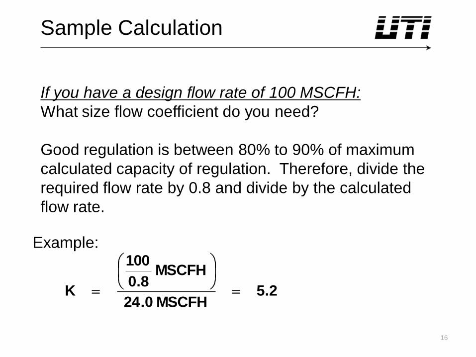
2.5MSCFH0.24
MSCFH8.0
100
K
If you have a design flow rate of 100 MSCFH:
What size flow coefficient do you need?
Good regulation is between 80% to 90% of maximum
calculated capacity of regulation. Therefore, divide the
required flow rate by 0.8 and divide by the calculated
flow rate.
Sample Calculation
Example:
16

3) Non-Critical flow where Regulator flow coefficients Km
K≠ c
4) Critical flow where Regulator flow coefficients Km
K≠ c
2
c
m
2Outlet
2
OutletInlet
2
c
mOutletInlet
2
c
m
m
K
K2
P4+PPK
K+PP
K
K
=P
2
Km
K4+1
InletP
2
cK
mK
4
=m
P
C
Determination of Intermediate Pressure Pm
17

Critical flow where Regulator flow coefficients Km
K≠ c
2
Km
K4+1
InletP
2
cK
mK
4
=m
P
C
Determination of Intermediate Pressure Pm
Pin = 100 Psig Pout =35 Psig, (Km =2) ≠ (Kc = 1)
Add 15 Psia to the inlet and outlet pressure to make them absolute pressures
814.13.250
115
P
P
out
in
Determine the intermediate pressure
?P
P
Outlet
Inlet
Question: Is Pin/Pout greater or less than 1.814?
Pin =115 Psia Pout =50 Psia Pm =? Psia Km = 2 Kc = 1
18

Intermediate Pressure Pm
Sample Calculation
Psia2.1082
1
24+1
1152
1
24
=mP
Critical flow where Regulator flow coefficients Km
K≠ c
2
K
mK4+1
InletP
2
cK
mK4
=mP
C
Determine the intermediate pressure
Pin =115 Psia Pout =50 Psia Pm =? Psia
Km = 2 Kc = 1
19

2
PK=Q m
Mscfh1.54=Q
Determine the capacity of the downstream regulator Kc = 1
814.12.250
2.108
Pm
Pin
2
2.1081=Q
mmin PPPK=Q
2.1082.1081152=Q
Mscfh2.54=Q
Determine the capacity of the upstream regulator Km =2
814.106.12.108
115
Pm
Pin
Intermediate Pressure Pm
Sample Calculation
(Km =2) ≠ (Kc = 1)
20

Note: Cg values are in SCFH
1.291CC
3417log=K g
1
Conversion Equation
for Cg & C1 Values to K Values
Conversion Equation for Cv & XT Values to Cg Values
Tvg XC40=C
v
g1
C
C=C
21

Use gas velocity for sizing the diameter of the inlet & outlet risers on regulator settings
40 MPH
60 MPH
54.5 MPH
80 feet per second is defined by API 12K as the erosion velocity
D 3.61Q
P
58.7ft
sec
D 2.95Q
P
88ft
sec
D 3.00Q
P
80ft
sec
2
2
22flow
3
elft
inch144
inchDπ
4
ft5280
Mile1
PsigP+Psia14.73
14.73Psia
MCF
1000ft
Hr
MCF=V
MPH=
DPsigP+Psia14.73
McfhQ511.5=V
2flow
flowel
D in Inches, Q in Mcfh, P in Psia
Sizing of Regulator Risers
22

Capacity Curves for Monitor Regulators
5 to 70 PSIG Outlet Pressures
Regulator Flow Curves
23

Regulator Flow Curves
Instructions for calculating maximum capacity of a monitor set of regulators
with identical orifice.
1. Locate inlet pressure curve on chart from previous slide
2. Locate maximum outlet pressure along Y axis
3. From the outlet pressure, follow the line across the chart left to right, until
it intersects the inlet pressure curve
4. Draw a vertical line down and read the base capacity along the X axis
5. To obtain the capacity of a set of regulators, with a K value greater than or
less than the base capacity K value of 1, multiply the base capacity by the
K value of the regulators
6. EXAMPLE: Calculate the maximum capacity of a monitored set of 2”
Sensus 441-57S regulators equipped with a 1 ½”doubleseatedinner
valves. K value equals 4.27. The inlet pressure is 60 psig and the outlet
pressure is 35 psig
24

Monitor Regulator Sizing Charts
1. Monitor Regulator Flow Curves
a. Simple ease to determine monitor set capacities
b. No calculations required
2. Monitor Regulator Flow Chart
a. Ease to follow step by step
b. Can be used for programming
25

Monitor Regulator Capacity Calculation
Flow Diagram
Pin
Pm
1.814Pm
Pout
1.814
Qm MSCFH Qc MSCFH
Q k Pin Pm Pm Q k Pm Pout Pout
Pin
Pout1.814Pm
4km
kc
2
Pin
1 4km
kc
2
Pm
km
kc
2
Pin
Pout
km
kc
2
Pin
Pout
2
4 Pout2
2km
kc
2
Pm
PmPin Pout
Upstream Downstream
YES
NO
YESNO
YES
NO
Q kPm
2Q k
Pin
2
Qm Qc
Yes No Yes
26

boost
Lock-uppressure
Set point
Droop
FLOW RATE ==>
99%
100%
98%
Regulator Outlet Droop
1. What is Droop? Droop is the decrease in outlet pressure from the
set point. As flow increases from the set point to maximum capacity
2. Spring and Diaphragm effect. As the spring gets weaker
(expanding) the diaphragm area gets larger. Therefore, a lower
pressure under the diaphragm will balance the force of the spring at a
greater valve opening
27

Regulator Performance Curves
28

X”
125
NEW SET POINT
NEW LOCK-UP PRESSURE
Regulator Performance Curves
29

30