monitor and sentinel user's guide - · pdf filemonitor and sentinel user's guide...
TRANSCRIPT

WorkHorse Monitor / Sentinel
User’s Guide
P/N 957-6228-00 (November 2007)


Table of Contents Monitor and Sentinel User's Guide ........................................................................................................... 1
Introduction...............................................................................................................................................................1 Technical Support ....................................................................................................................................................1 Overview ..................................................................................................................................................................1 Hardware Overview..................................................................................................................................................2
Battery Packs and Power Overview....................................................................................................................3 Optional External Battery Pack...........................................................................................................................5 Flash Memory Card ............................................................................................................................................5 Serial Communication Overview.........................................................................................................................6
Deployment Overview ..............................................................................................................................................7 Software Overview ...................................................................................................................................................7 Installing the Software ..............................................................................................................................................9
WorkHorse Preparation............................................................................................................................ 10 Visual Inspection ....................................................................................................................................................12 Seal the WorkHorse for Deployment ......................................................................................................................13
Install and Connect the Sentinel Battery...........................................................................................................14 Check all Mounting Hardware is Installed.........................................................................................................19
Bench Test................................................................................................................................................. 20 Setup the WorkHorse ADCP ..................................................................................................................................20 Connecting to the WorkHorse ................................................................................................................................22 Changing the Baud Rate in the ADCPs..................................................................................................................24 Testing the WorkHorse...........................................................................................................................................25
Compass Alignment..........................................................................................................................................26 Preparing for Calibration ...................................................................................................................26 Compass Calibration Verification ......................................................................................................27 Compass Calibration Procedure .......................................................................................................27
Optional Pressure Sensor Preparation...................................................................................................................30 Collecting Self-Contained Data ............................................................................................................... 32
Recover Data with WinSC......................................................................................................................................41 Viewing Data with WinSC.......................................................................................................................................42
Collecting Real-Time Data........................................................................................................................ 43 Sending the Commands to the WorkHorse ADCP .................................................................................................48 Viewing Data in Real-Time.....................................................................................................................................49
Where to Find More Information.............................................................................................................. 51
List of Figures Figure 1. WorkHorse Sentinel Exploded View ................................................................................ 2 Figure 2. WorkHorse Sentinel Battery Pack ................................................................................... 4 Figure 3. External Battery Pack Connection................................................................................... 5 Figure 4. Memory Card Overview................................................................................................... 5 Figure 5. I/O Cable Wiring Diagram ............................................................................................... 6 Figure 6. Visual Inspection Checklist............................................................................................ 11 Figure 7. WorkHorse Connections ............................................................................................... 20 Figure 8. Compass Calibration ..................................................................................................... 28

NOTES

Monitor and Sentinel User's Guide
P/N 957-6228-00 (November 2007) page 1
Monitor and Sentinel User's Guide
Introduction Thank you for purchasing the Teledyne RD Instruments (TRDI) WorkHorse Monitor/Sentinel Acoustic Doppler Current Profiler (ADCP). This User’s Guide will lead you through the steps required for a successful deployment. Please read the entire guide, and then follow the instruc-tions in the order they are presented. Additional information can be found in the WorkHorse Tech-nical Manual that is supplied on CD-ROM.
NOTE. To purchase a printed copy of the WorkHorse documentation (includes the WorkHorse Technical Manual and software guides), contact our Customer Service department at [email protected] or call (858) 842-2600 and order the WorkHorse Manual kit.
Technical Support If you have technical issues or questions involving a specific application or deployment with your instrument, contact our Field Service group: Teledyne RD Instruments Teledyne RD Instruments Europe
14020 Stowe Drive Poway, California 92064
2A Les Nertieres 5 Avenue Hector Pintus 06610 La Gaude, France
Phone +1 (858) 842-2600 Phone +33(0) 492-110-930
FAX +1 (858) 842-2822 FAX +33(0) 492-110-931
Sales – [email protected] Sales – [email protected]
Field Service – [email protected] Field Service – [email protected]
Customer Service Administration – [email protected] Web: http://www.rdinstruments.com
24/7 Technical Support +1 (858) 842-2700

Monitor and Sentinel User's Guide
page 2 Teledyne RD Instruments
Overview The first step is to become familiar with the Monitor/Sentinel ADCP. Read the short descrip-tions of the hardware and software that comes with the WorkHorse.
This Section Covers:
• Hardware Overview • Battery Packs and Power Overview • Serial Communication Overview • Deployment Overview • Software Overview • Installing the Software
Hardware Overview The WorkHorse Sentinel ADCP system consists of an ADCP, cables, battery pack, flash mem-ory card, and software. The WorkHorse Sentinel can also be used for direct-reading current profile operation. The ADCP requires the addition of a Windows® compatible computer to configure the ADCP and replay collected data.
The WorkHorse Monitor system consists of an ADCP, cables, and software. The Monitor does not include the internal battery or flash memory and therefore uses a shorter housing. The Sen-tinel and Monitor use the same electronics.
URETHANE FACE
BEAM 3 MARK
THERMISTOR
PRESSURE SENSOR(OPTIONAL)
TRANSDUCER HEAD
HOUSING
MEMORY CARD
INTERNAL BATTERYPACK
END-CAP
I/O CABLE CONNECTOR
Figure 1. WorkHorse Sentinel Exploded View

Monitor and Sentinel User's Guide
P/N 957-6228-00 (November 2007) page 3
The transducer assembly contains the transducer ceramics and electronics. Standard acoustic frequencies are 600 and 1200 kHz. See the outline drawings in the WorkHorse Technical Manual for dimensions and weights.
I/O Cable Connector – Input/Output (I/O) cable connects the WorkHorse ADCP to the com-puter.
Beam-3 Mark – The Beam-3 mark shows the location of Beam-3 (Forward).
Urethane Face – The urethane face covers the transducer ceramics. Never set the transducer on a hard surface. The urethane face may be damaged.
Housing – The WorkHorse housing allows deployment depths to 200 meters.
Thermistor – The Thermistor measures the water temperature.
Pressure Sensor – The optional pressure sensor measures water pressure (depth).
Transducer Head – The WorkHorse electronics and transducer ceramics are mounted to the transducer head. The numbers embossed on the edge of the transducer indicates the beam number. When assembling the unit, match the transducer beam number with the Beam 3 mark on the end-cap.
End-Cap – The end-cap holds the I/O cable connector. When assembling the unit, match the Beam 3 mark on the end-cap with beam 3 number on the transducer.
Internal Battery Pack – WorkHorse Sentinel ADCPs use an internal battery pack to provide power to the ADCP.
Flash Memory Card – WorkHorse Sentinel ADCPs come standard with one memory card. Two PCMCIA memory cards slots are available, with the total memory capacity not to exceed 1GB.
Battery Packs and Power Overview WorkHorse Monitor/Sentinel ADCPs require +20 to 50 VDC to operate. The standard AC Adapter runs on any standard AC power and supplies +48 VDC to run the WorkHorse when the batteries are not connected. The WorkHorse Sentinel’s internal battery supplies +42 VDC.
NOTE. The AC Adapter input voltage is sufficient to override the internal battery voltage (i.e. the ADCP will draw all power from the AC adapter even if the battery is installed and connected). Always use the AC adapter when testing the ADCP to conserve the battery power.
Keep in mind the following about Sentinel battery packs:
• TRDI specifies its battery packs to have 450 Watt-hours (Wh) of usable energy at 0°C.
• A Standard WorkHorse battery packs hold 28 ‘D-cell’ alkaline batteries with a voltage, when new, of approximately 42 VDC.
• When the capacity of a battery pack is 50% used, the voltage (measured across the battery connector under no-load conditions) falls to approximately 32 to 35 volts. However, keep in mind that this voltage is not an accurate predictor of remaining capacity.

Monitor and Sentinel User's Guide
page 4 Teledyne RD Instruments
• Transmitted power increases or decreases depending on the input voltage (within the voltage range of 20 to 50 VDC). A fresh battery provides +42 VDC. Batteries spend most of their life at a nominal voltage of +33 VDC.
NOTE. The transmitted power is decreased one DB if the input voltage drops from 42 VDC to 33 VDC. For a 600 kHz WorkHorse ADCP, each one DB drop will result in a decrease in range of one default depth cell.
• Batteries should be replaced when the voltage falls below 30 VDC (measured across the battery connector under no-load conditions).
• Battery packs differ from one to another.
• Store batteries in a cool dry location (0 to 21 degrees C).
• Do not store batteries inside the ADCP for extended periods. The batteries may leak.
• Use batteries within one year (shelf life).
NOTE. Battery replacement induces both single and double cycle compass errors. The compass accuracy should be verified after replacing the battery pack. The compass does not have to be recalibrated if the compass verification passes specification.
These compass effects can be avoided by using an optional external battery pack. The optional external battery housing holds two batteries, and can easily be replaced on-site. If the optional external battery is placed a minimum of 30 cm away from the ADCP, no compass calibration will be required.
INTERNALI/O CABLE
THREADEDROD (4)
WING NUT (4)
WASHER (4)
RUBBER BANDS
BATTERY PACK
LOCK WASHER (4)
BATTERY CABLE
SPACER (4)
DESICCANTRUBBER BAND
SUPPORT PLATE
Figure 2. WorkHorse Sentinel Battery Pack

Monitor and Sentinel User's Guide
P/N 957-6228-00 (November 2007) page 5
Optional External Battery Pack The optional External Battery Pack holds two 450 Watt-hours (Wh) batteries. To avoid affect-ing the compass, place the external battery case at least 30-cm away from the WorkHorse ADCP.
EXTERNAL BATTERY PACK
SENTINEL ADCP
EXTERNAL BATTERY PACK CABLE
MINIMUM 30 cm APART
TO COMPUTER/DUMMY PLUG Figure 3. External Battery Pack Connection
NOTE. The optional external battery pack can be used with both the WorkHorse Monitor and Sentinel model ADCPs.
Flash Memory Card WorkHorse Sentinel ADCPs come standard with one memory card. Two PCMCIA memory cards slots are available, with the total memory capacity not to exceed 2GB. Memory cards are not included with the Monitor ADCP. The PC Card recorder is located on the Digital Signal Processor (DSP) board inside the Workhorse’s electronics. To recover data, the card can be removed and used in a personal computer (PC), or left in the Workhorse, and accessed by using WinSC (see the WinSC and PlanADCP User's Guide).
Figure 4. Memory Card Overview

Monitor and Sentinel User's Guide
page 6 Teledyne RD Instruments
Serial Communication Overview The standard communications settings for the WorkHorse Monitor/Sentinel is RS-232, 9600-baud, no parity, 8 data bits and 1 stop bit. Self-contained applications receive no benefit from setting a faster baud rate.
You can set the WorkHorse for baud rates other than 9600 baud using the CB command (see the WorkHorse Technical Manual). If you make the new baud rates permanent with the CK command, WinSC and BBTalk will search for the correct settings if you use the Auto Detect function, which searches for the WorkHorse’s current serial port and baud rate (see “Connecting to the WorkHorse,” page 22). If you tell the programs these settings, you will save time required for searching. Both WinSC and BBTalk will use the last communication set-ting for future use.
Change Communication Setting. Changing a switch setting on the PIO board will change the communication setting between RS-232 and RS-422. The switch is in plain view on the top circuit board, near the cable connectors. Its settings are plainly marked on the board. If the serial protocol is set for RS-422 and your computer expects RS-232, you will need an RS-232 to RS-422 adapter between the ADCP cable and your computer. This user’s guide assumes that you use RS-232. There is no reason to use RS-422 for Self-Contained operations.
REDYEL
BLK/WHTBLK
41
32985
P2
12564
37
POWER +POWER -
COMMUNICATION RETURN
RS-232 IN / CH A RS-485A / RS-422 OUT ARS-232 OUT / CH A RS-485B/ RS-422 OUT B
CH B RS-485A / RS-422 IN ACH B RS-485B / RS-422 IN B
P1BLKWHTBLUBRNGRN
P3
76
5
4
12
3
12 3
4
PIN 1PIN 6
Figure 5. I/O Cable Wiring Diagram

Monitor and Sentinel User's Guide
P/N 957-6228-00 (November 2007) page 7
Deployment Overview WorkHorse Sentinel deployments are most often Self-Contained but can be Real-Time. Typi-cally, deployments are considered to be Self-Contained when the WorkHorse ADCP is re-motely deployed and powered using internal batteries. In this configuration, no external con-nections to the WorkHorse are made during the deployment. However, the WorkHorse can be connected to external power. This power can be provide either by an external battery case or from shore. This type of deployment is still considered Self-Contained, but this guide may not consider all of the possibilities of this application.
WinSC is the software package for self-contained WorkHorse setup, data collection, and data review. PlanADCP (part of WinSC) lets you enter known or “best-guess” values for the vari-ous WorkHorse profiling parameters and shows predictions of expected results. The Work-Horse Sentinel can be used for several-month autonomous current profile deployments from temporary or permanent mountings in the ocean, near-shore, harbors, and lakes.
Real-Time use refers to the fact you are viewing the data as the WorkHorse ADCP collects it via a personal computer. This data is also stored on the computer to allow for data playback and processing at a later time. Use PlanADCP to create the command file to set the values for the various WorkHorse profiling parameters and WinADCP to view the data.
Software Overview You will need several software programs to test and collect data with the WorkHorse ADCP.
WinSC & PlanADCP
WinSC and PlanADCP are designed to set up a Sentinel WorkHorse ADCP for collecting data. Specifically, PlanADCP will set the WorkHorse commands cor-rectly.
The PlanADCP screen shows you an overview of your setup and the resulting consequences of your deployment.
For more information see the WinSC and PlanADCP User’s Guide and “Collecting Self-Contained Data,” page 32 or “Collecting Real-Time Data,” page 43.

Monitor and Sentinel User's Guide
page 8 Teledyne RD Instruments
BBTalk
BBTalk is a terminal emulator that al-lows your computer to communicate with the WorkHorse via RS422 or RS232.
This guide does not go into detail about the operation of BBTalk. For more in-formation see the RDI Tools User’s Guide.
WinADCP Main Screen
WinADCP gives users a visual display of the entire set of data. You can zoom in on a portion of the data for closer analysis and export data to text or Mat-Lab files.
Use WinADCP to view color contour and time-series plots of data collected with an WorkHorse Monitor in real-time or playback data collected with an Work-Horse Sentinel.
For detailed information on how to use WinADCP, see the WinADCP User's Guide.

Monitor and Sentinel User's Guide
P/N 957-6228-00 (November 2007) page 9
Installing the Software You will be installing several software packages. These will be required for testing and de-ployments.
The WorkHorse software requires the following:
• Windows XP®, Windows 2000®, or Windows 98®
• Pentium class PC 233 MHz (350 MHz or higher recommended)
• 32 megabytes of RAM (64 MB RAM recommended)
• 6 MB Free Disk Space (20 MB recommended)
• One Serial Port (two High Speed UART Serial Ports recommended)
• Minimum display resolution of 800 x 600, 256 color (1024 x 768 recommended)
Software Installation
a. Insert the compact disc into your CD-ROM drive and then follow the browser instructions on your screen. If the browser does not appear, com-plete Steps "b" through "d."
b. On the Windows task bar, click the Start button, and then click Run.
c. Type <drive>:launch. For example, if your CD-ROM drive is drive D, type d:launch.
d. Follow the browser instructions on your screen

Monitor and Sentinel User's Guide
page 10 Teledyne RD Instruments
WorkHorse Preparation Proper WorkHorse ADCP preparation is critical for a successful deployment. In this section we will prepare the WorkHorse Monitor/Sentinel ADCP for deployment. Deployment Checklist
Visually inspect the WorkHorse Check the I/O Cable and connector pins for damage Check the housing condition for damage Check the transducer faces are clean and free from defects
Seal the WorkHorse for deployment Install and connect the battery (WorkHorse Sentinel ADCP only) Check Recorder PC card is installed (WorkHorse Sentinel ADCP only) Use fresh desiccant (2 bags) inside WorkHorse ADCP Install new o-rings; use silicone lubricant Check all mounting hardware is installed
Bench Tests Test the WorkHorse using BBTalk Verify the compass alignment using BBTalk; if necessary, re-calibrate Check the recorder status using BBTalk (WorkHorse Sentinel ADCP only)
Final Preparation for Deployment Are biofouling precautions needed? Clean the optional pressure sensor port copper screw Zero the pressure sensor (optional) at deployment site with AZ-command

Monitor and Sentinel User's Guide
P/N 957-6228-00 (November 2007) page 11
TRANSDUCER HEADCHECK O-RINGSAND MOUNTINGHARDWARE AREINSTALLED
ELECTRONICS ANDBATTERY PACKSCHECK MEMORY CARD AND BATTERIES AREINSTALLED
END-CAPCHECK O-RINGS ANDMOUNTING HARDWAREARE INSTALLED
I/O CABLE CONNECTORINSTALL DUMMY PLUG
HOUSINGCHECK FORCRACKS
URETHANE TRANSDUCER FACESREMOVE BARNACLES AND CHECK FOR CRACKS
VISUALLY INSPECT THE ADCP
Figure 6. Visual Inspection Checklist

Monitor and Sentinel User's Guide
page 12 Teledyne RD Instruments
Visual Inspection Before connecting the WorkHorse ADCP, make a quick visual inspection of the components to make sure nothing is damaged.
Check the I/O Cable and connector pins for damage
Roll the I/O cable rubber retaining strap up so that it does not hinder plug re-moval.
Remove the dummy plug or cable by pulling with a straight-out motion. Do not wiggle the connector up; this can dam-age the connector pins. A slight side-to-side wiggle as you are pulling on the cable is OK.
Inspect the pins for damage. Make sure that they are straight and that there is no corrosion on the metal surfaces.
Check the WorkHorse for damage
Inspect the WorkHorse ADCP for dam-age. There should be no cracks or peel-ing surfaces.

Monitor and Sentinel User's Guide
P/N 957-6228-00 (November 2007) page 13
Check the transducer faces are clean and free from defects
Inspect the WorkHorse ADCP for dam-age. There should be no cracks or peel-ing surfaces.
Seal the WorkHorse for Deployment Before you put the WorkHorse ADCP into the water, you must prepare it for deployment.
• Install and connect the battery (WorkHorse Sentinel ADCP only)
• Replace the desiccant inside the WorkHorse
• Install new o-rings; use silicone lubricant
• Check all mounting hardware is installed
NOTE. Only the end-cap removal instructions are included in this Quick Start Guide. If you need access to the WorkHorse electronics, the transducer head must be removed. Please refer to the WorkHorse Technical Manual for instructions.

Monitor and Sentinel User's Guide
page 14 Teledyne RD Instruments
Install and Connect the Sentinel Battery To install the WorkHorse Sentinel battery pack, do the following steps. Read the WorkHorse Technical Manual for details.
Place the WorkHorse Sentinel ADCP on its side.
Make note of the location of Beam 3. The Beam 3 mark on the end cap should be aligned with the label on the housing and the Beam 3 mark on the transducer.
Loosen and remove the four M6 bolts holding the end-cap to the housing.
Gently slide the end-cap and battery assembly out of the housing. The two cables are long enough to allow the as-sembly to be placed next to the housing (see next photo).
Disconnect the battery cable and inter-nal I/O cable going to the common mode choke on the top PC Board.

Monitor and Sentinel User's Guide
P/N 957-6228-00 (November 2007) page 15
Remove the four wing nuts, lock wash-ers, and washers holding the battery pack onto the posts.
Remove the support plate.
Slide out the used battery pack.
Slide a new battery pack onto the four posts. Make sure the I/O cable is not pinched by the battery pack.
Use the large rubber bands (supplied with each new pack) to hold the cables in place.
Test the battery pack voltage by meas-uring across the battery connector under no-load conditions. The voltage should be +42 VDC for a new battery pack.
Position the support plate over the four posts.
Place a flat washer, lock washer, and wing nut on each of the four posts. Tighten the wing nuts firmly to hold the battery in place.
Place a battery pack rubber band (two spare rubber bands are provided with each new battery) around all four wing nuts. This will prevent the wing nuts from backing off the post.
CAUTION. The WorkHorse Sentinel battery pack is held in place by four sets of washers, lock washers, and wing nuts. If the wing nuts are not tight, the assembly of washers and wing nut can become loose and eventually fall onto the PIO board. This has caused the PIO board to short out. Place a rubber band around the wing nuts to help hold them in place.

Monitor and Sentinel User's Guide
page 16 Teledyne RD Instruments
Clean the O-ring groove. Be sure the groove is free of foreign matter, scratches, indentations, or pitting. Use lint free wipes or a wood scrapper to clean the groove.
Never use Q-tips to clean the O-ring groove; loose fibers or lint can provide a leakage path.
Place a small amount of silicone lube on the O-ring and spread it over the entire O-ring surface. The O-ring should ap-pear “shiny”. Wipe off any excess lube.
Place the O-ring in the O-ring groove on the housing.
Place a new desiccant pack and mois-ture indicator into the housing. Desic-cant bags are used to dehumidify the housing interior.
Remove the new desiccant bags from the airtight aluminum bag.
Remove the old desiccant bags and in-stall two new ones. Place the desiccant bags under the rubber bands on the bat-tery pack or place on top of the PC boards.

Monitor and Sentinel User's Guide
P/N 957-6228-00 (November 2007) page 17
Connect the battery and internal I/O ca-ble going to the common mode choke.
CHECK FOR PINCHED WIRES
Slide the end-cap onto the housing mak-ing sure that the beam 3 mark is aligned with the label on the housing and the beam 3 mark on the transducer head.
Make sure no wires become pinched or that the O-ring falls out of the groove.
It may be easier to tip the Work-Horse on the transducer head when connecting the end-cap to the housing. Make sure to protect the transducer faces and prevent the WorkHorse from tipping over.

Monitor and Sentinel User's Guide
page 18 Teledyne RD Instruments
Install all four sets of hardware until “finger-tight.”
Tighten the bolts in small increments in a “cross” pattern until the split washer flattens out, and then tighten each bolt ¼ turn more to compress the face seal O-ring evenly.
Tighten the bolts to the recommended torque value of 5.6 Newton-meters (50 pound-inches).

Monitor and Sentinel User's Guide
P/N 957-6228-00 (November 2007) page 19
Check all Mounting Hardware is Installed If the housing is not properly sealed prior to deployment, the WorkHorse ADCP will be de-stroyed.
Transducer Head to Housing Seal
Visually inspect the mating surfaces of the housing to transducer head to en-sure that there are no obstructions. The faces should be parallel to one another and there should be no gaps. Check to ensure that the titanium fasteners hold-ing the housing together are tight.
The recommended torque value for the transducer head 8-mm bolts is 9.6 Newton-meters (85 pound-inches).
End-Cap to Housing Seal
Visually inspect the mating surfaces of the end-cap to housing to ensure that there are no obstructions. The faces should be parallel to one another and there should be no gaps. Check to en-sure that the titanium fasteners holding the housing together are tight.
The recommended torque value for the end-cap 6-mm bolts is 5.6 Newton-meters (50 pound-inches).
CAUTION. Do not replace the titanium hardware with any other hardware. Corrosion will result.
If the WorkHorse was opened, read the WorkHorse Technical Manual – Maintenance section for details on WorkHorse re-assembly.

Monitor and Sentinel User's Guide
page 20 Teledyne RD Instruments
Bench Test The bench-testing process ensures that the WorkHorse ADCP is working properly before you put it in the water. The bench-test procedure will involve powered tests that will verify that the WorkHorse ADCP’s electronics and transducers are functioning.
This Section Covers:
• Setup the WorkHorse ADCP
• Test the WorkHorse ADCP
• Compass alignment
Setup the WorkHorse ADCP You will now connect the WorkHorse ADCP to a power supply and a computer with the TRDI software installed.
Sentinel ADCP
BATTERY(NOT CONNECTED)
MEMORY CARD(INSTALLED)
Monitor ADCPRS-232 to RS-422
CONVERTER(Monitor ADCP only)
I/O CABLE
POWER SUPPLY
48 VDC
COMPUTER
WinSC
BBTalk
100-240 VAC50/60 Hz
Figure 7. WorkHorse Connections
CAUTION. WorkHorse Sentinel batteries are shipped inside the WorkHorse ADCP but not connected. Connect the battery and seal the WorkHorse ADCP before deployment.
For testing, the battery can be disconnected to save battery power. If the battery is connected, use the AC adapter to override the battery voltage to conserve the battery (see “Battery Packs and Power Overview,” page 3).

Monitor and Sentinel User's Guide
P/N 957-6228-00 (November 2007) page 21
Connect the I/O Cable to WorkHorse
If you have not done so, connect the I/O cable to the WorkHorse ADCP. Do so by pushing straight in against the con-nector. Roll the retaining strap over the connector.
Place a light amount of silicone lubri-cant on the connector pins (rubber por-tion only). This will make it easier to connect or remove the I/O cable and dummy plug.
Connect the I/O Cable to Computer and Power Supply
Attach the I/O cable to your computer's communication port. The standard communications settings are RS-232, 9600-baud, no parity, 8 data bits and 1 stop bit. Self-contained applications receive no benefit from setting a faster baud rate.
Connect the power supply to the power cable.

Monitor and Sentinel User's Guide
page 22 Teledyne RD Instruments
Connecting to the WorkHorse Use these next steps to “talk” to the WorkHorse ADCP.
Start BBTalk
Start the BBTalk program (for help on using BBTalk, see the RDI Tools User's Guide).
On the Connect To screen, select WorkHorse.
Select the COM port the WorkHorse ADCP cable is connected to.
Click Next.
Enter the Baud Rate, Parity, Stop Bits, and Flow Control. If you are unsure of the settings, leave them at the default settings.
Click Next.
Click Finish.

Monitor and Sentinel User's Guide
P/N 957-6228-00 (November 2007) page 23
Wakeup
On the File menu, click Break (you can also press the End key to send a break or press the B button on the Toolbar).
You should see the wakeup message appear on the log file window.
If the wakeup message is not readable, do the following.
On the File menu, click Properties. Click the Auto Detect ADCP button. Click OK when the WorkHorse is de-tected. Try to wakeup the WorkHorse again.
What if the WorkHorse Does Not Respond
If your WorkHorse ADCP does not respond, check the serial port, cables, AC power, and bat-tery connection (Sentinel only). If necessary, refer to the Troubleshooting section in the WorkHorse Technical Manual.
CAUTION. WorkHorse Sentinel batteries are shipped inside the WorkHorse ADCP but not connected. Connect the battery and seal the WorkHorse ADCP before deployment.

Monitor and Sentinel User's Guide
page 24 Teledyne RD Instruments
Changing the Baud Rate in the ADCPs The ADCP can be set to communicate at baud rates from 300 to 115200. The factory default baud rate is always 9600 baud. The baud rate is controlled via the CB-command. The follow-ing procedure explains how to set the baud rate and save it in the ADCP. This procedure as-sumes that you will be using the program BBTalk that is supplied by Teledyne RD Instruments.
[BREAK Wakeup A] WorkHorse Broadband ADCP Version 16.28 RD Instruments (c) 1996-2005 All Rights Reserved. > >cr1 [Parameters set to FACTORY defaults]
Connect the ADCP to the computer and apply power.
Start the BBTalk program and establish communications with the ADCP. Wakeup the ADCP by sending a break signal with the End key.
At the ">" prompt in the communication window, type CR1 then press the Enter key. This will set the ADCP to the fac-tory default settings.
BAUD RATE CB-command
300 CB011 1200 CB111 2400 CB211 4800 CB311 9600 CB411 (Default) 19200 CB511 38400 CB611 57600 CB711 115200 CB811
Send the CB-command that selects the baud rate you wish. The table on the left shows the CB-command settings for different baud rates with no parity and 1 stop bit.
For example, to change the baud rate to 115200, at the ">" prompt in the com-munication window, type cb811 then press the Enter key.
The CB? command will identify the communication setting.
>cb? CB = 411 ----------------- Serial Port Control (Baud [4=9600]; Par; Stop) >cb811 >CK [Parameters saved as USER defaults] >cb? CB = 811 ----------------- Serial Port Control (Baud [8=115200]; Par; Stop) >
BBTalk will send the command CK to save the new baud rate setting.
Exit BBTalk.
The ADCP is now set for the new baud rate. The baud rate will stay at this set-ting until you change it back with the CB-command.
Exit BBTalk so the communication port is available for use with other pro-grams.

Monitor and Sentinel User's Guide
P/N 957-6228-00 (November 2007) page 25
Testing the WorkHorse Before deploying the WorkHorse ADCP, it is a good idea to make sure that it is working prop-erly. This simple test checks that the WorkHorse ADCP is able to communicate with the com-puter and runs the diagnostic tests.
Testing the WorkHorse
Using BBTalk, click File, Send a Break to send the wakeup command (BREAK) to the WorkHorse ADCP.
On the File menu, click Send Script File. Click the Browse button “...”.
On the Files of Type box select RDI Script (*.rds).
Select the TestWH.rds script file and click Open.
Follow the prompts on the screen.
To review the test results, open the WH_Test.txt results log file (*.txt) with any text editor (i.e. NotePad).
Monitor and Sentinel User's Guide
page 26 Teledyne RD Instruments
Compass Alignment The main reason for compass calibration is battery replacement. Each new battery carries a different magnetic signature. The compass calibration algorithm corrects for the distortions caused by the battery to give you an accurate measurement. You should be aware of the fol-lowing items:
• We recommend against calibrating the WorkHorse ADCP while on a ship. The ship’s motion and magnetic fields from the hull and engine will likely prevent successful calibration.
• If you think your mounting fixture or frame has some magnetic field or mag-netic permeability, calibrate the WorkHorse ADCP inside the fixture. Depend-ing on the strength and complexity of the fixture’s field, the calibration proce-dure may be able to correct it.
NOTE. If the WorkHorse Sentinel battery module was removed and replaced back in the same orientation, the compass does not require calibration. If the battery core is replaced, you must verify the compass.
Battery replacement induces both single and double cycle compass errors. The compass accuracy should be verified after replacing the battery pack. The compass does not have to be recalibrated if the compass verification passes specification.
These compass effects can be avoided by using an optional external battery pack. The external battery housing holds two batteries, and can easily be replaced on-site. If the external battery is placed a minimum of 30 cm away from the WorkHorse ADCP, no compass calibration will be required.
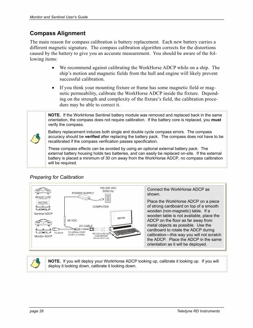
Preparing for Calibration
Sentinel ADCP
BATTERY(CONNECTED)
MEMORY CARD(INSTALLED)
Monitor ADCPRS-232 to RS-422
CONVERTER(Monitor ADCP only)
I/O CABLE
POWER SUPPLY
48 VDC
COMPUTER
BBTalk
100-240 VAC50/60 Hz
Connect the WorkHorse ADCP as shown.
Place the WorkHorse ADCP on a piece of strong cardboard on top of a smooth wooden (non-magnetic) table. If a wooden table is not available, place the ADCP on the floor as far away from metal objects as possible. Use the cardboard to rotate the ADCP during calibration—this way you will not scratch the ADCP. Place the ADCP in the same orientation as it will be deployed.
NOTE. If you will deploy your WorkHorse ADCP looking up, calibrate it looking up. If you will deploy it looking down, calibrate it looking down.

Monitor and Sentinel User's Guide
P/N 957-6228-00 (November 2007) page 27
CAUTION. If you calibrate the compass in one direction (up or down) and deploy the WorkHorse ADCP in the opposite direction (i.e. calibrate it in a downward position and deploy it in an upward position) the compass calibration will be invalid. Compass errors in excess of 5 degrees may occur.
Compass Calibration Verification Compass calibration verification is an automated built-in test that measures how well the com-pass is calibrated. The procedure measures compass parameters at every 5º of rotation for a full 360º rotation. When it has collected data for all required directions, the ADCP computes and displays the results.
[BREAK Wakeup A] WorkHorse ADCP Edition 43.xx Teledyne RD Instruments (c) 1996-2006 All Rights Reserved.
>
Using BBTalk, send a Break to wake up the WorkHorse ADCP (press the END key).
>AX ---------------------------------------------------------------------- RDI Compass Error Estimating Algorithm Press any key to start taking data after the instrument is setup. Rotate the unit in a plane until all data samples are acquired... rotate less than 5°/sec. Press Q to quit. N NE E SE S SW W NW N ^ ^ ^ ^ ^
At the > prompt, type AX and press the Return key.
HEADING ERROR ESTIMATE FOR THE CURRENT COMPASS CALIBRATION: OVERALL ERROR: Peak Double + Single Cycle Error (should be < 5(): ( 1.55( DETAILED ERROR SUMMARY: Single Cycle Error: ( 1.54( Double Cycle Error: ( 0.07( Largest Double plus Single Cycle Error: ( 1.61( RMS of 3rd Order and Higher + Random Error: ( 0.31(
Rotate the WorkHorse ADCP slowly 360 degrees (approximately 5 degrees per second). Pay particular attention to the Overall Error.
If the overall error is less than 2°, the compass does not require alignment. You can align the compass to reduce the overall error even more (if desired).
Compass Calibration Procedure The built-in automated compass calibration procedure is similar to the alignment verification, but requires three rotations instead of one. The WorkHorse ADCP uses the first two rotations to compute a new calibration matrix and the third to verify the calibration. It will not accept the new matrix unless the calibration was carried out properly, and it asks you to verify that you want to use the new calibration if it is not as good as the previous calibration. While you are turning the WorkHorse for the two calibration rotations, the WorkHorse ADCP checks the quality of the previous calibration and displays the results. It compares these results with the results of the third calibration rotation.
There are two compass calibrations to choose from; one only corrects for hard iron while the other corrects for both hard and soft iron characteristics for materials rotating with the Work-Horse ADCP. Hard iron effects are related to residual magnetic fields and cause single cycle

Monitor and Sentinel User's Guide
page 28 Teledyne RD Instruments
errors while soft iron effects are related to magnetic permeability that distorts the earth’s mag-netic field and causes double cycle errors. In general, the hard iron calibration is recom-mended because the effect of hard iron dominates soft iron. If a large double cycle error exists, then use the combined hard and soft iron calibration.
UPWARD DEPLOYMENT
DOWNWARD DEPLOYMENT
Spin 90 degreesTilt >10 degrees
Place the Dummy Plug or small block under the end-cap to make the tilt less than or equal to 20 degrees.
Spin 90 degreesTilt >10 degrees
Figure 8. Compass Calibration
[BREAK Wakeup A] WorkHorse ADCP Edition 43.xx Teledyne RD Instruments (c) 1996-2006 All Rights Reserved. >
Using BBTalk, send a Break to wake up the WorkHorse ADCP (press the END key).
>AR Do you really want to write over the active fluxgate calibration data [y or n]?Y Fluxgate Calibration Matrices Updated with Factory Original Values. >
At the > prompt, type AR and press the Return key. Type Y to return the Flux-gate Calibration Matrices with the fac-tory original values.

Monitor and Sentinel User's Guide
P/N 957-6228-00 (November 2007) page 29
>AF ---------------------------------------------------------------------- Field Calibration Procedure Choose calibration method: a. Remove hard iron error (single cycle) only. b. Remove hard and soft iron error (single + double cycle). c. Help. d. Quit.
At the > prompt, type AF and press the Return key. Choose option “b” to start the calibration procedure.
Tilt the unit any direction so that the combined tilt magnitude is within the 10°-20° range indicated below. 0° 10° 20° 30° ^ ^***** ok tilt *****^ ^ ♦ 0.4° Pitch and 19.1° Roll are acceptable. Ok to continue [y, n]?
Tilt the WorkHorse ADCP. Tilt an up-ward-looking WorkHorse with a block under one side of the end-cap. A 35-mm block will give you an 11-degree tilt. Tilt a downward looking WorkHorse by placing it on one of the beams.
Check the on-screen instructions to see if the orientation is OK. Adjust as nec-essary.
When prompted, press “y” to continue and rotate the WorkHorse ADCP slowly 360 degrees (approximately 5 degrees per second).
Now tilt the unit at least 10° in a different direction. SUGGESTIONS: Facing up: place the block under the end cap to either side of where the block was for the first rotation - not on the opposite side of the end cap!. Facing down: place the ADCP facing down on either of the two beams that are closest to the one you just used. Do not place the ADCP on the opposite beam. -19.3° Pitch and -0.5° Roll. Tilt is OK. Press any key to continue...
The second rotation requires the Work-Horse ADCP to be tilted 15 degrees in another direction than from the first rota-tion. Follow the on-screen instructions to orient the WorkHorse ADCP correctly.
When prompted, press any key to con-tinue and rotate the WorkHorse slowly 360 degrees (approximately 5 degrees per second).
Successfully evaluated compass performance after the field calibration update. Press any key to continue... Making new calibration parameters permanent. Calibration parameters have been updated in RAM and Flash. ---------------------------------------------------------------------- Field Calibration Procedure Hard and Soft Iron Calibration Compass field calibration procedure is complete. >>> Total error before calibration: 2.3° <<< >>> Total error after calibration: 0.2° <<<
The third rotation requires the Work-Horse ADCP to be tilted 15 degrees in another direction than from the first and second rotations. Follow the on-screen instructions to orient the WorkHorse cor-rectly.
If the calibration procedure is success-ful, it records the new calibration matrix to nonvolatile memory. The WorkHorse will not change its matrix unless the calibration is properly carried out.

Monitor and Sentinel User's Guide
page 30 Teledyne RD Instruments
Optional Pressure Sensor Preparation In order to read the water pressure (depth), water must be able to flow through the copper screw on the pressure sensor. Antifoulant paint will block the sensor’s port (a small hole that is drilled through the copper screw). You should tape off the screw during anti-fouling paint ap-plication.
This means that the sensor port is not fully protected from bio fouling. The sensor port is sur-rounded by the antifouling paint, but bio fouling may build up on the screw, and eventually clog the sensor port. However, most organisms do not seem to find the small amount of un-painted surface attractive. If it is logistically possible to periodically inspect/clean the pressure sensor screw, it is highly recommended. This tradeoff situation must be analyzed for individ-ual deployments. Unfortunately, the location of the deployment site usually dictates action in this regard.
NOTE. The pressure sensor is optional. It may not be included on your system.
CAUTION. The pressure sensor is filled with silicone oil. Never poke a needle or other object through the copper screw while the screw is installed over the pressure sensor. You will perforate the sensor, causing it to fail.
Do not remove the cover disc or attempt to clean the surface of the pressure sensor. The diaphragm is very thin and easy to damage.
Do not remove the pressure sensor. It is not field replaceable.
Use the following procedure to clean the screw.
Place the WorkHorse on its’ end-cap. Use a soft pad to protect the Work-Horse.
Use a straight-slot screwdriver to re-move the copper screw.
Gently clean out the hole in the copper screw with a needle.
Install the copper screw. Tighten the screw “finger tight” (0.226 N-m, 2 lbf-in).
CAUTION. Do not over tighten the screw or you may strip the threads on the plastic cover disc. If this happens, return the WorkHorse ADCP to TRDI for repair.

Monitor and Sentinel User's Guide
P/N 957-6228-00 (November 2007) page 31
[BREAK Wakeup A] WorkHorse ADCP Edition 43.xx Teledyne RD Instruments (c) 1996-2006 All Rights Reserved. > > > >AZ >
Zero the Pressure Sensor
Use the AZ-command to zero out the pressure sensor at the deployment site, before putting the WorkHorse into the water.
Connect and apply power to the system.
Start BBTalk and wakeup the Work-Horse ADCP (press the END key).
Type AZ and press the Return key.
Exit BBTalk.

Monitor and Sentinel User's Guide
page 32 Teledyne RD Instruments
Collecting Self-Contained Data WinSC works as a shell program to launch the PlanADCP program. PlanADCP is designed to create a command file that will be used to set up a WorkHorse ADCP for collecting data. In this example we will start WinSC, use PlanADCP to develop the command file, and then go back to the WinSC program to continue with the testing, deployment, and recovery of data.
Start WinSC. Select Configure an WorkHorse for a new deployment and click OK.
Planning
The first step of the deployment wizard will start PlanADCP.
Click Next to continue.
Instrument
Select the type of WorkHorse ADCP you want to create a command file for.
Click Next to continue.
Monitor and Sentinel User's Guide
P/N 957-6228-00 (November 2007) page 33
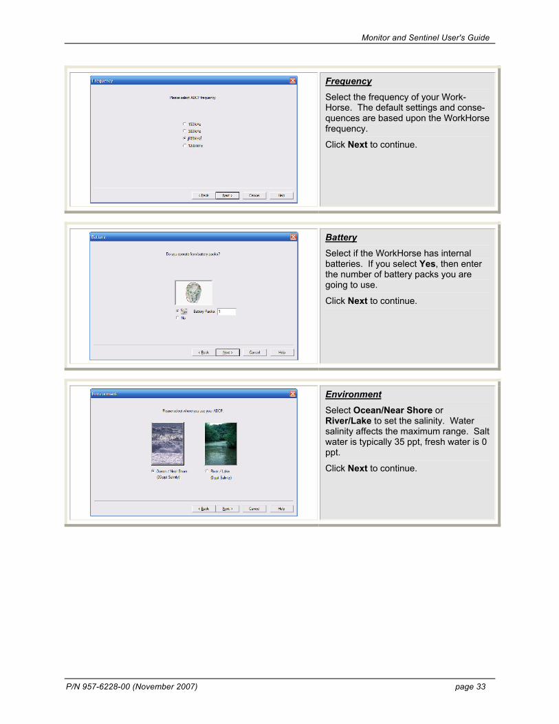
Frequency
Select the frequency of your Work-Horse. The default settings and conse-quences are based upon the WorkHorse frequency.
Click Next to continue.
Battery
Select if the WorkHorse has internal batteries. If you select Yes, then enter the number of battery packs you are going to use.
Click Next to continue.
Environment
Select Ocean/Near Shore or River/Lake to set the salinity. Water salinity affects the maximum range. Salt water is typically 35 ppt, fresh water is 0 ppt.
Click Next to continue.

Monitor and Sentinel User's Guide
page 34 Teledyne RD Instruments
Water Profiles
Select the depth range you wish to measure. The maximum depth range is dependent on the WorkHorse fre-quency, water salinity, water tempera-ture, and the depth of the WorkHorse.
Click Next to continue.
Application
Select Moored (No Bottom Track) for a self-contained deployment.
Click Next to continue.
Resolution
Set the depth cell (bin) size. Adjust the depth cell (bin) size as necessary to get at least 10 depth cells (bins). A larger depth cell (bin) size decreases the stan-dard deviation, but shallow water situa-tions may need to use small depth cells (bins) to get more data points.
PlanADCP will set the number of depth cells (bins) so that the consequence last depth cell (bin) range is approximately 10% greater than the depth range set in the previous step.
Click Next to continue.

Monitor and Sentinel User's Guide
P/N 957-6228-00 (November 2007) page 35
Data Storage
Select where to store the data. Data can be stored internally, sent out the serial port, or both. If you selected In-ternally, enter the amount of memory installed.
Click Next to continue.
Water Profiling Timing
Select how many ensembles per hour you want to record.
Click Next to continue.
Duration
Enter the expected duration of the WorkHorse deployment from the time of the first water profiling ping (either im-mediately or first ping date/time). This duration does not produce a command to instruct the WorkHorse to stop data collection; it is for estimating conse-quences only. This duration is used to estimate the following consequences:
• Battery usage
• Ensembles
• Storage required
Click Next to continue.

Monitor and Sentinel User's Guide
page 36 Teledyne RD Instruments
The wizard is now finished.
Click Finish.
The PlanADCP (Basic) Screen opens using the settings you selected with the wizard. Review the consequences (see the WinSC and PlanADCP User’s Guide for details).
On the PlanADCP (Basic) Screen click the Advanced button to bring up the Advanced setting screen.
Advanced Screen
Uncheck the Ping Immediately After Deployment box and enter a date and time you want the WorkHorse to begin pinging.
Start sample intervals on the minute by using a delayed start up. Instead of having your 10-minute sample intervals start at 12:36:47, delay startup a few minutes to have samples start at 13:00:00.

Monitor and Sentinel User's Guide
P/N 957-6228-00 (November 2007) page 37
Expert Screen
On the PlanADCP (Advanced) Screen click the Expert button to bring up the Expert setting screen.
You can view the commands that will be sent to the WorkHorse.
Back to WinSC
Click the BackToSC menu to return to WinSC.
NOTE. At this point, the WorkHorse ADCP should be prepared for deployment, using battery power, and sealed.
The second step will set the WorkHorse ADCP’s clock to the computer’s time and date using the TS-command.
Click Next to continue.

Monitor and Sentinel User's Guide
page 38 Teledyne RD Instruments
The third step will verify the compass using the AX-command.
Note: If the internal batteries were re-placed, this step will only verify the compass; you must align the compass prior to using the WinSC wizard.
Click Next to continue.
The fourth step will run the pre-deployment tests Deploy?, System?, TS?, PS0, PA, PC2, RS, and PC1-commands.
Click Next to continue.
The fifth step will zero the pressure sen-sor using the AZ-command.
Click Next to continue.

Monitor and Sentinel User's Guide
P/N 957-6228-00 (November 2007) page 39
The sixth step will erase the recorder using the RE-command. Uncheck the Skip Erasing Recorder Data box if you want to erase the data.
CAUTION: Once erased, the data is not recoverable.
Click Next to continue.
The seventh and final step in the De-ployment Wizard will send the com-mands from the command file to the WorkHorse.
Click Next to send the commands. When the commands have been sent to the WorkHorse, you should see a mes-sage “You have successfully deployed the ADCP.”
Click OK.
NOTE. The WorkHorse must be powered with the batteries, sealed, and ready to deploy before you click Next.

Monitor and Sentinel User's Guide
page 40 Teledyne RD Instruments
Save Deployment File
If you have not already saved the de-ployment file, you will be prompted to name the deployment. Choose and use Deployment Names carefully: they help you identify and organize all the data and log files associated with each de-ployment.
The command file and deployment log file will be saved when the deployment file is saved. For example, if you save the deployment file as Dpl1_.dpl, then the command file will be saved as Dpl1_.whp and the log file will be saved as Dpl1_.scl.
Before deploying the WorkHorse ADCP, scroll through the deployment log file and look for error messages. Correct as needed and re-send the commands.
Photo courtesy of J. Bornhoeft.
Deploy and Recover the WorkHorse
Once the commands have been sent to the WorkHorse, proceed as follows.
• Disconnect the I/O cable and install the dummy plug on the WorkHorse ADCP’s end-cap.
• Deploy the WorkHorse ADCP.
CAUTION. Do not send a break, any other command, or run any other programs once the commands have been sent to the WorkHorse ADCP or your commands will be over-written.
Disconnect the I/O cable before turning off power to the computer. Some computers may send a break signal out the serial ports when shutting down.

Monitor and Sentinel User's Guide
P/N 957-6228-00 (November 2007) page 41
Recover Data with WinSC
Connect and power up the WorkHorse ADCP.
Start WinSC.
At the Welcome Screen select Re-cover Data from an ADCP’s Recorder or from the File menu, select Recover Recorder Data.
Select the directory where the data will be written.
WinSC will increase the baud rate set in the Com Settings window to 115200 BAUD to reduce the download time.

Monitor and Sentinel User's Guide
page 42 Teledyne RD Instruments
Viewing Data with WinSC
On the File menu, click Open.
On the Files of Type box, select ADCP Data (*.0*).
Select the file and click Open.
The data file will display all of the en-sembles.
To select a subsection of the data file, use the View menu, Ensemble Selec-tion.
To quickly select a section, hold the Control key while dragging the mouse over the area to be selected.
Display Controls.
Right-click inside any window to bring up the display menu.
To increase the size of a window, click Maximize Pane button.
To increase the contrast of the con-toured plot, select Contoured.
You can increase the contrast between cells and contours by using the Zone Cells or Zone Contours.
To change the colors of the plot or other plot controls, click Properties.
To select the range of a contoured plot, click Ranges.

Monitor and Sentinel User's Guide
P/N 957-6228-00 (November 2007) page 43
Collecting Real-Time Data PlanADCP is designed to create a command file that will be used to set up a WorkHorse ADCP for collecting data. In this example we will use PlanADCP to develop the command file, and BBTalk to send the commands to the WorkHorse. Then we will use the WinADCP program to view the data in real-time.
Start PlanADCP. On the File menu, click New.
Instrument
Select the type of WorkHorse ADCP you want to create a command file for.
Click Next to continue.
Frequency
Select the frequency of your WorkHorse ADCP. The default settings and conse-quences are based upon the WorkHorse frequency.
Click Next to continue.

Monitor and Sentinel User's Guide
page 44 Teledyne RD Instruments
Battery
Select if the WorkHorse has internal batteries. If you select Yes, then enter the number of battery packs you are going to use.
Click Next to continue.
Environment
Select Ocean/Near Shore or River/Lake to set the salinity. Water salinity affects the maximum range. Salt water is typically 35 ppt, fresh water is 0 ppt.
Click Next to continue.
Application
Select Moored (No Bottom Track) for a self-contained deployment.
Click Next to continue.

Monitor and Sentinel User's Guide
P/N 957-6228-00 (November 2007) page 45
Water Profiles
Select the depth range you wish to measure. The maximum depth range is dependent on the WorkHorse fre-quency, water salinity, water tempera-ture, and the depth of the WorkHorse.
Click Next to continue.
Resolution
Set the depth cell (bin) size. Adjust the depth cell (bin) size as necessary to get at least 10 depth cells (bins). A larger depth cell (bin) size decreases the stan-dard deviation, but shallow water situa-tions may need to use small depth cells (bins) to get more data points.
PlanADCP will set the number of depth cells (bins) so that the consequence last depth cell (bin) range is approximately 10% greater than the depth range set in the previous step.
Click Next to continue.
Data Storage
Select where to store the data. Data can be stored internally, sent out the serial port, or both. If you selected In-ternally, enter the amount of memory installed.
Click Next to continue.

Monitor and Sentinel User's Guide
page 46 Teledyne RD Instruments
Water Profiling Timing
Select how many ensembles per hour you want to record.
Click Next to continue.
Duration
Enter the expected duration of the WorkHorse deployment from the time of the first water profiling ping (either im-mediately or first ping date/time). This duration does not produce a command to instruct the WorkHorse to stop data collection; it is for estimating conse-quences only. This duration is used to estimate the following consequences:
• Power requirements
• Ensembles
• Storage required
Click Next to continue.
The wizard is now finished.
Click Finish.

Monitor and Sentinel User's Guide
P/N 957-6228-00 (November 2007) page 47
The PlanADCP (Basic) Screen opens using the settings you selected with the wizard. Review the consequences (see the WinSC and PlanADCP User’s Guide for details).
On the PlanADCP (Basic) Screen click the Advanced button to bring up the Advanced setting screen.
Advanced Screen
Uncheck the Ping Immediately After Deployment box and enter a date and time you want the WorkHorse ADCP to begin pinging.
Start sample intervals on the minute by using a delayed start up. Instead of having your 10-minute sample intervals start at 12:36:47, delay startup a few minutes to have samples start at 13:00:00.
Setup Advanced Screen
On the PlanADCP (Advanced) Screen click the Expert button to bring up the Expert setting screen.
You can view the commands that will be sent to the WorkHorse.

Monitor and Sentinel User's Guide
page 48 Teledyne RD Instruments
Save the Command File
On the File menu, click Save. Name the command file and click Save.
Sending the Commands to the WorkHorse ADCP [BREAK Wakeup A] WorkHorse ADCP 43.xx Teledyne RD Instruments (c) 1996-2006 All Rights Reserved. >
Wakeup the WorkHorse
Start BBTalk. On the File menu, click Break (you can also press the End key to send a break or and press the B button on the Toolbar).
You should see the wakeup message appear on the log file window.
Create a Log File
Press F3 and create a log file. Name the file and use *.000 for the file extension.
Send the Commands to the Work-Horse
Press F2 and use the Browse button to locate the command file.
You should see the commands appear on the log file window and the Work-Horse ADCP’s response.
Carefully review the log file window and make sure that no command created an error message.

Monitor and Sentinel User's Guide
P/N 957-6228-00 (November 2007) page 49
Viewing Data in Real-Time WinADCP has the ability to automatically update the reading of a file as real-time data collec-tion is occurring. When the file size increases, (due to real-time data collection) Monitor will automatically reread the file at selected intervals and display the contents. When Monitor is enabled and the file size is changing, all menu items except Monitor will be unavailable.
Start WinADCP
Start WinADCP. On the File menu, click Open.
Select the log file created with BBTalk (see “Sending the Commands to the WorkHorse ADCP,” page 48).
On the Monitor menu, select ON.
You can change the interval by clicking Monitor, Interval.
Enter the monitor interval in seconds. For example, a 20 minute ensemble would be 1200 seconds.

Monitor and Sentinel User's Guide
page 50 Teledyne RD Instruments
WinADCP has two main graphic display forms. The form located in the upper right portion of the screen is called the Whole Set. The form located across the bottom half of the display is called the Sub Set. Each of these forms dis-plays a portion of the entire data set as a color contour. In addition to the color contour, Sub Set displays the user se-lected Profile, Series, and Ancillary data.
The Whole Set form is displayed in the upper right-hand portion of WinADCP. When a file containing a Binary Output Data Format is opened, the entire set of the selected data type is displayed as a color contour located within the Whole Set form.
By holding down the Spacebar and then pressing the Left mouse button, the user can drag the mouse to select a por-tion of the entire data set. When the mouse button is released, the selected portion of the Whole Set is marked by a blinking box outline. The blinking box outlines a set of data called the Se-lected Set.

Monitor and Sentinel User's Guide
P/N 957-6228-00 (November 2007) page 51
Where to Find More Information Congratulations! You have completed the WorkHorse Monitor/Sentinel User’s Guide. For more detailed information, see the following sections in the WorkHorse Technical Manual.
Installation. Use this section to plan your installation requirements. This guide includes specifications and dimensions for the WorkHorse ADCP (including outline installation draw-ings).
Maintenance. This section covers WorkHorse ADCP maintenance. Use this section to make sure the WorkHorse is ready for a deployment.
Test. Use this section to test the WorkHorse ADCP.
Troubleshooting. This section includes a system overview and how to troubleshoot the WorkHorse ADCP. If the WorkHorse fails a built-in test or you cannot communicate with the system, use this guide to help locate the problem.
Commands and Output Data Format. This section contains a reference for all commands and output data formats used by the WorkHorse ADCP.

Monitor and Sentinel User's Guide
page 52 Teledyne RD Instruments
NOTES