molecularly imprinted intelligent scaffolds for tissue ... · molecularly imprinted intelligent...
TRANSCRIPT

Molecularly Imprinted Intelligent Scaffolds for Tissue Engineering Applications
Mariana Isabel Fonseca Neves
DISSERTATION FOR THE
DEGREE OF MASTER OF SCIENCE IN BIOENGINEERING
AT THE FACULDADE DE ENGENHARIA DA UNIVERSIDADE DO PORTO
AND INSITUTO DE CIÊNCIAS BIOMÉDICAS ABEL SALAZAR

2 Mariana Isabel Fonseca Neves
- This page was intentionally left in blank -

Molecularly Imprinted Intelligent Scaffolds
for Tissue Engineering Applications
Mariana Isabel Fonseca Neves
Dissertation
for the Degree of Master of Science in Bioengineering,
at the Faculdade de Engenharia da Universidade do Porto
And Instituto de Ciências Biomédicas Abel Salazar
Supervisor: Dr. Pedro Granja
Co-supervisor: Dr. Manuela Gomes
September 2016

4 Mariana Isabel Fonseca Neves
© Mariana Isabel Fonseca Neves, 2016

This work was financed by Portuguese funds through FCT - Fundação para a Ciência
e a Tecnologia/Ministério da Ciência, Tecnologia e Inovação in the framework of the
project “RECOGNIZE – Intelligent scaffolds by molecular recognition for advanced
applications in regenerative medicine” - UTAP-ICDT/CTM-BIO/0023/2014.

6 Mariana Isabel Fonseca Neves

“I am among those who think that science has great beauty. A scientist in his laboratory is
not only a technician: he is also a child confronting natural phenomena that impress him as
though they were fairy tales.
[…] Neither do I believe that the spirit of adventure runs any risk of disappearing in our
world. If I see anything vital around me, it is precisely that spirit of adventure, which seems
indestructible and is akin to curiosity.”
Marie Skłodowska Curie

8 Mariana Isabel Fonseca Neves

Mariana Isabel Fonseca Neves i
Acknowledgments
First of all, I would like to thank my supervisor, Professor Pedro Granja, for all the
opportunities he provided to me; for believing in me and my capabilities and for always
motivating me to go further; for his unconditional availability, and finally, for his inspiring
professionalism and optimism. I would also like to thank my co-supervisor, Professor Manuela
Gomes, for all her support and motivation throughout this work.
An honest thank you goes to all my colleagues from Biocarrier for the way they welcomed
me into the group, for their friendship and good moments, their help and motivation, both at
professional and personal levels, and for all that I have learned with every one of you throughout
these last six months.
To all my classmates, with whom I spent my best moments of these last five years and with
whom I grew up and learnt so much. In particular, to all my ladies Rita Ribeiro, Bárbara Mesquita,
Andreia Granja, Eva Carvalho, Rita Castro, Sofia Assis, Lúcia Rebelo, Rita Pinto and Ana
Nascimento: for all the dramas and joys we spent together, a special thank you!
To my aunt and uncle, Luísa and João, who supported me in my first years of this course
like I was a daughter of your own, an everlasting thank you.
I would also like to thank my brother João for all the pranking and teasing, that only an
older brother like you knows how to do… and also for being an example that resilience and
willpower are the way to reach our dreams.
To my boyfriend Pedro, for being with me throughout these last ten years of my short life,
in particular throughout this long five-year journey of mine trying to be an engineer and ending

ii Mariana Isabel Fonseca Neves
up being a biotechnologist; for always having shown me what I am capable of and all that I have
learnt with you. For that, and all the rest, a huge thank you.
Finally, to my parents, Fátima and Licínio, for the example you have always been to me; for
having stimulated me to feel curious about everything and always wanting to learn more; for
having showed me, through your own effort, that perseverance and work are fundamental for
professional success and that nothing comes to our hands if we are simply waiting without
looking; for all the values you taught me that made me who I am today; for all the opportunities
you gave me, a lot of times with sacrifice, so I could go further. And most of all, for teaching me
that if I fell, I could always get up, and that I could walk ahead without having to look back. Thank
you.

Mariana Isabel Fonseca Neves iii
Agradecimentos
Em primeiro lugar, queria agradecer ao meu orientador, Professor Pedro Granja, por todas
as oportunidades que me providenciou; por acreditar em mim e nas minhas capacidades e por
me ter sempre motivado a tentar chegar mais longe; pela disponibilidade incansável sempre que
precisei e finalmente pelo seu inspirador profissionalismo e optimismo.
Queria também agradecer à minha co-orientadora, Professora Manuela Gomes, por todo
o seu apoio e motivação ao longo do trabalho.
Um sincero agradecimento a todos os meus colegas do Biocarrier pelo modo como me
receberam, pela amizade e momentos bem passados, pela ajuda e motivação a nível profissional
e pessoal, e por tudo o que pude aprender com vocês ao longo destes seis meses.
A todos os meus colegas de turma, com os quais passei os meus melhores momentos
destes últimos cinco anos e com os quais cresci e aprendi tanto. Em especial a todas as minhas
meninas: Rita Ribeiro, Bárbara Mesquita, Andreia Granja, Eva Carvalho, Rita Castro, Sofia Assis,
Lúcia Rebelo, Rita Pinto e Ana Nascimento. Por todos os dramas e alegrias que passamos juntas,
um obrigado!
Aos meus tios, Luísa e João, que me apoioaram e me receberam durante os primeiros anos
deste curso como se fosse vossa filha, um eterno obrigado.
Tenho também de agradecer ao meu irmão João, por todas as traquinices e arrelias que só
um irmão mais velho como tu sabe fazer… E também por seres um exemplo para mim de como
a resiliencia e a vontade são o caminho para atingirmos aquilo que queremos e sonhamos.
Ao meu namorado Pedro, por me ter acompanhado nos últimos dez anos desta minha curta
vida, e em especial nesta minha longa travessia de cinco anos a tentar ser engenheira, mas a

iv Mariana Isabel Fonseca Neves
acabar a ser uma biotecnóloga; por sempre me teres mostrado do que sou capaz e por tudo o
que aprendi contigo. Por isso, e por tudo o resto, um enorme obrigado.
Finalmente, aos meus pais, Fátima e Licínio, por todo o exemplo que sempre foram para
mim; por me terem estimulado a sentir curiosidade por tudo e a querer sempre aprender mais
e mais; por me terem mostrado, através do vosso próprio esforço, que a preserverança e o
trabalho são fundamentais para o sucesso profissional e que nada vem ter connosco se
simplesmente estivermos à espera sem procurar; por todos os valores que me transmitiram e
me fazem ser a pessoa que sou hoje; por todas as oportunidades que me deram, muitas vezes
com sacrifício vosso, para que pudesse chegar mais longe. E sobretudo por me ensinarem que
se caísse me podia levantar, e que podia andar para a frente sem olhar para trás. Obrigada.

Mariana Isabel Fonseca Neves v
Abstract
It is widely accepted that material-cell interactions are mediated and affected by the type
of molecules adsorbed to the material. Such key concept has driven the tissue engineering field
to pursuit different ways of modifying or functionalizing materials, achieving a better control
over molecular adsorption and triggering of favorable cellular response.
Molecular imprinting is a technology inspired by highly selective interactions, such as
antibody/antigen bonding, which aims to induce molecular recognition into polymeric materials.
In order to do so, polymerization occurs in the presence of a template molecule, i.e., the
molecule of interest. Once polymerization is accomplished and the template molecule is
removed, specific cavities either in shape or position of binding sites are formed and available
to selectively recognize any molecule such as the template used. This feature can be an
interesting approach for scaffolds used for tissue engineering applications by enabling specific
molecular adsorption.
Even though this technology is widely described for low molecular weight molecules, the
same does not occur for molecular imprinting of high molecular weight molecules
(macromolecules), such as proteins, which are the ones that bear greater interest for Tissue
Engineering. The high molecular weight and size of these molecules, together with their complex
structure, lead to obstacles in the molecular imprinting process which are not addressed for
small molecules. Besides, most of the existent literature is intended for applications which do
not require mild or biocompatible conditions (e.g. biosensing).
The main aim of the project presented herein was to develop and study a biocompatible
molecular imprinting system based on a photosensitive polymer, methacrylated alginate. The
premature profile of the system required the study of basic features inherent either to the
vi Mariana Isabel Fonseca Neves
material or the molecular imprinting process itself. In order to optimize the system and compare
the obtained results with the literature, the chosen template molecule was bovine serum
albumin, a model protein.
On the first stage of development, methacrylation of alginate was optimized and achieved,
with polymeric solutions forming gel discs under UV light exposure. In this stage, two different
methacrylated alginate materials were produced which differed in their pH value (5 or 7).
An evaluation of swelling behavior of these materials was then performed under different
pH and salt conditions in order to further optimized production steps related to the molecular
imprinting process. Results showed that both pH and presence of salts affected the swelling
behavior. While increasing the pH to 7.4 allowed the swelling of the discs, lower pH values lead
to deswelling events. The effect of salts on swelling behavior and template removal was also
evaluated by comparing the effects of Tris solutions, with or without the presence of divalent
cations salts, with the effects provoked by deionized water.
Once an optimized molecular imprinting protocol was set, template removal and rebinding
capacity were studied and characterized for molecularly imprinted polymer discs using different
protein quantification approaches. Results revealed for template removal were promising as
they ranged from 70-98%, depending on the type of material used. Results concerning the
capacity of the molecularly imprinted material to recognize the template molecule showed no
significant differences when comparing to a non-imprinted material. These lack of recognition
was most likely caused by the high swelling and deswelling rates observed during the whole
processing.
Overall, this study enabled the understanding of the effect of different external stimuli in
the developed material and how these potentially affected the molecular imprinting process.
The preliminary studies developed herein are crucial to further define the right directions to
follow in order to successfully achieve molecular recognition and ultimately transpose this
system to biomolecules with more specific interest for tissue engineering applications.

Mariana Isabel Fonseca Neves vii
Table of Contents
Acknowledgments ......................................................................................................................... i
Agradecimentos ............................................................................................................................ iii
Abstract .......................................................................................................................................... v
Table of Contents......................................................................................................................... vii
Abbreviation List ........................................................................................................................... xi
List of Figures .............................................................................................................................. xiii
List of Tables .............................................................................................................................. xvii
Outline .......................................................................................................................................... 1
Chapter 1 ....................................................................................................................................... 5
Introduction .................................................................................................................................. 5
1.1. Natural body response to injury ............................................................................................ 7
1.2. Tissue engineering and the relevance of cell-instructing scaffolds ....................................... 9
1.3. Molecularly imprinted polymers .......................................................................................... 11
1.3.1. Molecular imprinting characteristics ................................................................................ 11
1.3.2. Molecular imprinting considerations ................................................................................ 12
1.3.3. Molecularly imprinted intelligent scaffolds ...................................................................... 14
1.3.3.4. Molecular imprinting mechanisms................................................................................. 16

viii Mariana Isabel Fonseca Neves
1.4. Hydrogels for macromolecular imprinting ........................................................................... 20
1.4.1. Alginates and alginate composite polymeric hydrogels ................................................... 21
1.4.2. Chitosan and chitosan composite hydrogels .................................................................... 26
1.5. Cell imprinting ...................................................................................................................... 28
1.6. Future prospects for molecular imprinting .......................................................................... 29
Chapter 2 ..................................................................................................................................... 33
Aim of the Project ....................................................................................................................... 33
Chapter 3 ..................................................................................................................................... 35
Materials and Methods .............................................................................................................. 35
3.1. Alginate Methacrylation ....................................................................................................... 35
3.2. 1H NMR analysis ................................................................................................................... 36
3.3. Production of methacrylated alginate non-imprinted and molecularly imprinted discs .... 37
3.4. Swelling behavior of alginate discs ...................................................................................... 38
3.5. Photoinitiator influence in absorbance reading at 280nm .................................................. 40
3.6. Morphological analysis by Cryo-SEM ................................................................................... 40
3.7. Mechanical characterization ................................................................................................ 40
3.8. Template removal ................................................................................................................ 41
3.9. Rebinding Assay ................................................................................................................... 41
3.10. Protein Quantification ........................................................................................................ 42
3.10.1. Protein quantification by analysis of supernatant .......................................................... 42
3.10.2. Protein quantification in digested discs .......................................................................... 42
3.10.3. Protein quantification by GTA method ........................................................................... 44
3.11. Statistical analysis............................................................................................................... 46
Chapter 4 ..................................................................................................................................... 47
Results and Discussion ............................................................................................................... 47

Mariana Isabel Fonseca Neves ix
4.1. Alginate modification ........................................................................................................... 47
4.1.2. Alginate methacrylation .................................................................................................... 48
4.2. Molecular imprinting protocol optimization ........................................................................ 53
4.2.1. Effect of different solutions in alginate discs .................................................................... 54
4.2.2. Disc production and template removal protocol optimization ........................................ 59
4.3. Template removal analysis and characterization................................................................. 64
4.3.1. Template removal quantification by analysis of supernatant .......................................... 64
4.3.2. Template removal quantification by analysis of digested discs ........................................ 65
4.3.2. Template removal quantification by GTA method ........................................................... 69
4.4. Rebinding assays .................................................................................................................. 75
4.4.1. Rebinding analysis by protein quantification in digested discs ........................................ 78
4.4.2. Rebinding analysis by GTA method ................................................................................... 81
4.5. General overview of the MIP-ALMA system ........................................................................ 85
Chapter 5 ..................................................................................................................................... 89
Conclusions and Perspectives .................................................................................................... 89
References .................................................................................................................................. 91
Supplementary data ................................................................................................................... 99

x Mariana Isabel Fonseca Neves
- This page was intentionally left in blank -

xi
Abbreviation List
AcOH – Acetic acid
AL - Alginate
ALMA 5 – Methacrylated alginate, pH 5
ALMA 7 – Methacrylated alginate, pH 7
AU – Arbitrary Units
BMP – Bone morphogenetic proteins
BSA – Bovine serum albumin
Cyt – Cytochrome
Cryo-SEM – Cryo Scanning electron microscopy
DAP – Diammonium phosphate
DI water – Deionized water
ECM – Extracellular matrix
EMIPM – Embedded molecularly imprinted polymer microspheres/microcapsules
EtOH – Ethanol
FGF – Fibroblast growth factor
Fn – Fibronectin
GTA – Glutaraldehyde
Hb – Hemoglobin
H NMR – Proton nuclear magnetic resonance
HSA – Human serum albumin
IF – Imprinting factor
IGF – Insulin-like growth factor
IntDen – Integrated Density
xii Mariana Isabel Fonseca Neves
Lyz – Lysozyme
MA – Methacrylate/methacrylic anhydride
MI – Molecular imprinting
MIP – Molecularly imprinted polymer
MPC – Methacryloyloxyethyl phosphorylcholine
NIP – Non-imprinted polymer
PAAm - Polyacrylamide
PDGF – Platelet derived growth factor
PDMS – Polydimethylsiloxane
PGA – Polyglycolic acid
pI – Isoelectric point
PIM – Post-imprinting modifications
PLGA – Poly(lactic-co-glycolic) acid
PLLA - Poly-L-lactic acid
Q – Rebinding capacity
RGD – Arginine-Glycine-Aspartic acid tripeptide
RT – Room Temperature
SDS – Sodium dodecyl sulfate
SEM – Scanning Electron Microscopy
SMIPM – Surface molecularly imprinted polymer microspheres/microcapsules
SR – Swelling Ratio
TE – Tissue Engineering
UV – Ultraviolet
VEGF – Vascular endothelial growth factor

Mariana Isabel Fonseca Neves xiii
List of Figures
Figure 1. Molecular imprinting process. ....................................................................................... 6
Figure 2. Molecular imprinting strategies for macromolecules. ................................................. 15
Figure 3. Molecular structure of alginate and chitosan building blocks. .................................... 20
Figure 4. Applications of molecular imprinting in tissue engineering (TE). ................................ 30
Figure 5. The four main stages of development of this project. ................................................. 35
Figure 6. Molecular structure of methacrylic anhydride ............................................................ 36
Figure 7. Molecular structure of Irgacure 2959 .......................................................................... 37
Figure 8. Spacer-based approach used to produce methacrylated alginate discs. .................... 38
Figure 9. Schematic representation of samples used throughout the molecular imprinting
process and for rebinding assay. ................................................................................................. 43
Figure 10. Example of measurements performed in projected images obtained by inverted
confocal microscopy (excitation at 488 nm). .............................................................................. 45
Figure 11. Alginate methacrylation reaction with methacrylic anhydride. ................................ 49
Figure 12. ALMA 5 and ALMA 7 polymer solutions. .................................................................... 50
Figure 13. 1H NMR spectra of alginates produced in 10h (A) and 5h methacrylation reactions (B).
..................................................................................................................................................... 51
Figure 14. Comparison between 1H NMR spectra of non-modified alginate (A) and modified
alginates ALMA 5 (B) and ALMA 7 (C). ........................................................................................ 52
Figure 15. Effect of different solutions and incubation time in the swelling ratio of ALMA 5 and
ALMA 7 discs exposed to 60s and 70s of UV light. ...................................................................... 57
Figure 16. Absorbance spectra of incubation solutions after 1h incubation time...................... 58
Figure 17. Effect of solution, volume and time of incubation in the amount of removed BSA from
ALMA 5 and ALMA 7 alginate discs. ............................................................................................ 60

xiv Mariana Isabel Fonseca Neves
Figure 18. Effect of thickness in the amount of protein removed. ............................................. 61
Figure 19. ALMA 5 (left) and ALMA 7 (right) discs as produced. ................................................ 62
Figure 20. Representative Cryo-SEM images of ALMA 5 and ALMA 7 discs. .............................. 63
Figure 21. Amount of BSA removed in ALMA 5 and ALMA 7 discs (A) and percentage of template
removal (B) by protein quantification in the supernatant (incubation solution). ...................... 64
Figure 22 Amount of BSA removed in ALMA 5 and ALMA 7 discs (A) and percentage of template
removal (B) by protein quantification in digested discs. ............................................................ 66
Figure 23. Swelling profile of ALMA 5 and ALMA 7 NIP and MIP discs during template removal
protocol. Maximum swelling ratio of approximately 7 for ALMA 5 and 9 for ALMA 7 discs at 48h.
..................................................................................................................................................... 67
Figure 24. Images obtained by Zoe Fluorescent Cell imager for ALMA 5 NIP (A) and MIP (B) discs
at different timepoints of production. ........................................................................................ 70
Figure 25. Representative images of standard samples obtained by inverted confocal
microscopy. ................................................................................................................................. 71
Figure 26. Calibration curve obtained by analysis of inverted confocal microscopy images to
correlate the Mean Gray Value (A.U.) with the amount of BSA (mg/mL) present in discs. ....... 72
Figure 27. Representative images of samples before (A and C) and after (B and D) template
removal protocol obtained by inverted confocal microscopy. ................................................... 73
Figure 28. Representation of mean gray value of NIP and MIP discs (A) and amount of protein
present in MIP discs and corresponding template removal (B) before (0h) and after template
removal protocol (48h) determined by GTA method. ................................................................ 74
Figure 29. Swelling profile of ALMA 5 and ALMA 7 NIP and MIP discs during template removal
(3h and 48h) and rebinding protocol (72h of rebinding assay, total 120h). ............................... 76
Figure 30. Amount of BSA present in ALMA 5 and ALMA 7 NIP and MIP discs after 72h incubation
in 0.1% and 1% BSA solution in 0.9% NaCl (pH 4.2). ................................................................... 78
Figure 31. Rebinding capacity (amount of BSA adsorbed/absorbed during rebinding assay) of
ALMA 5 and ALMA 7 NIP and MIP discs after 72h incubation in 0.1% and 1% BSA solution in 0.9%
NaCl (pH 4.2). .............................................................................................................................. 80
Figure 32. Calibration curve obtained by analysis of inverted confocal microscopy images to
correlate the Mean Gray Value (A.U.) with the amount of BSA (mg/mL) present in discs. ....... 82
Figure 33. Representative images of ALMA 5 MIP and NP samples before (A and B) and after (C
and D) template removal protocol, and after 72h incubation in 1% BSA in a 0.9% NaCl solution

Mariana Isabel Fonseca Neves xv
(E and F) or solely in 0.9% in NaCl solution (G and H), obtained by inverted confocal microscopy.
..................................................................................................................................................... 82
Figure 34. Representation of Mean gray value of NIP and MIP discs during rebinding assay (A)
and amount of protein present in and adsorbed/absorbed into NIPs and MIPs (B) after
incubation in 1% BSA solution or 0.9% NaCl (internal controls) for 72h determined by GTA
method. ....................................................................................................................................... 83

xvi Mariana Isabel Fonseca Neves
- This page was intentionally left in blank -

Mariana Isabel Fonseca Neves xvii
List of Tables
Table 1. Recently developed systems on epitope imprinting of biomolecules. ......................... 18
Table 2. Molecularly imprinted polymers (MIPs) developed with natural polymers, namely
alginate, chitosan, and other synthetic polymers. ...................................................................... 22
Table 3. Studies performed to optimize the template removal protocol. .................................. 41
Table 4. Methacrylation protocols tested and gel formation capacity of produced materials. . 48
Table 5. Studies performed to optimize the template removal protocol and corresponding
specifications. .............................................................................................................................. 59
Table 6. Amount of BSA removed in ALMA 5 and ALMA 7 discs and percentage of template
removal determined by protein quantification in supernatant (incubation solution). .............. 65
Table 7. Amount of BSA removed in ALMA 5 and ALMA 7 discs and percentage of template
removal determined by protein quantification in digested discs. .............................................. 66
Table 8. Amount of BSA present in ALMA 5 and ALMA 7 NIP and MIP discs after 72 h incubation
in 0.1 % and 1 % BSA solution in 0.9 % NaCl (pH 4.2). ................................................................ 79
Table 9. Rebinding capacity (amount of BSA adsorbed/absorbed during rebinding assay) of ALMA
5 and ALMA 7 NIP and MIP discs after 72h incubation in 0.1% and 1% BSA solution in 0.9% NaCl
(pH 4.2). ....................................................................................................................................... 80

xviii Mariana Isabel Fonseca Neves
- This page was intentionally left in blank -

Mariana Isabel Fonseca Neves 1
Outline
This work is divided into four main chapters. A general overview of the currently available
literature on molecular imprinting and its potential applications in tissue engineering is explored
in Chapter 1 – Introduction. In Chapter 2 – Aim of the Project, both general particular aims of
this thesis are enounced and specified. In Chapter 3 – Materials and Methods, all methodologies
performed during this project are described. Chapter 4 – Results and Discussion presents and
explores all relevant results obtained throughout this project. In Chapter 5 – Conclusions and
Perspectives, the main results of this project are highlighted and future lines of work are
proposed.

2 Mariana Isabel Fonseca Neves
- This page was intentionally left in blank -

Mariana Isabel Fonseca Neves 3
The following Chapter corresponds to a review article already accepted for publication in the journal Tissue Engineering.
Molecularly Imprinted Intelligent Scaffolds for Tissue Engineering Applications
Mariana I. Neves1,2,3, Marissa E. Wechsler4,5, Manuela E. Gomes6, Rui L. Reis6,
Pedro L. Granja1,2,3,7, Nicholas A. Peppas4,5,8,9,10
1 Instituto de Investigação e Inovação em Saúde (i3S), Universidade do Porto, Porto, Portugal 2 Instituto de Ciências Biomédicas Abel Salazar (ICBAS), Universidade do Porto, Porto, Portugal 3 Faculdade de Engenharia da Universidade do Porto (FEUP), Porto, Portugal 4 Department of Biomedical Engineering, The University of Texas at Austin, Austin, TX, USA 5 Institute of Biomaterials, Drug Delivery and Regenerative Medicine, The University of Texas at Austin, Austin, TX, USA 6 3B’s Research Group, Universidade do Minho, Guimarães, Portugal 7 Instituto de Engenharia Biomédica (INEB), Universidade do Porto, Porto, Portugal 8 McKetta Department of Chemical Engineering, The University of Texas at Austin, Austin, TX, USA 9 Department of Surgery and Perioperative Care, Dell Medical School, The University of Texas at Austin, Austin, TX, USA 10 Division of Pharmaceutics, College of Pharmacy, The University of Texas at Austin, Austin, TX, USA

4 Mariana Isabel Fonseca Neves
- This page was intentionally left in blank -
Mariana Isabel Fonseca Neves 5
Chapter 1 Introduction
Molecular imprinting is a widely investigated technology with applications in the fields of
chemical sensing, chromatography, immunoassays, antibody mimicking, artificial enzymes and
catalysis processes [1, 2]. Molecular imprinting is a technology based on natural molecular
events (e.g., antibody/antigen interactions and enzyme catalysis) which aims to incorporate
molecular memory into a material using intelligent polymers [3, 4].
Intelligent polymers are macromolecular systems that exhibit strong thermodynamic
interaction with the surrounding environment and with associated components. Therefore, an
intelligent polymer material has strong interactions with the environment based on pH-, or
temperature sensitivity, but most importantly based on thermodynamic interactions with a
recognitive compound. This “intelligence” is rendered to the polymer either by external
decoration with required functional groups, or (better) by internal molecular imprinting of
micro- and nanocavities that provide recognitive characteristics.
Therefore, the fundamental idea for these new technology platforms is to combine a
template molecule with a functional monomer giving rise to a polymer network (after
crosslinking and removal of the template) with template-specific cavities in size, shape and
chemical functionality [5] (Fig. 1). The ability of these molecular imprinted polymers to then
recognize template molecules through thermodynamic interacts present the intelligent
capabilities of these polymers.
Molecular imprinting is well characterized for low-molecular weight molecules although,
despite the promising results, products based on this technology are currently not available on

6 Mariana Isabel Fonseca Neves
the market [2]. In contrast, molecular imprinting of high-molecular weight molecules exhibit
several obstacles, such as, size, structure, functionality and solubility which are not relevant
when imprinting small molecules [6]. The large size of these molecules restricts their transfer
within highly crosslinked polymer networks during both template removal and rebinding
studies. The complex structure of biomacromolecules (e.g., proteins) plays an important role in
their functionality, leading to high sensitivity to pH, ionic strength, temperature and organic
solvents [6, 7]. Despite these challenges, studies have reported results of the molecular
imprinting of proteins supporting its application, namely in the fields of biosensing and
chromatography [8-15].
Figure 1. Molecular imprinting process. Once the appropriate template molecule, functional monomer(s) and crosslinker(s) are selected, all components are mixed together in a proper solvent (e.g. deionized water, phosphate buffer) forming the pre-polymerization complex (template-functional monomer). Polymerization is then allowed to take place and specific cavities and binding sites are stabilized. Finally, removal of the template and other washing steps eliminate unreacted monomer and crosslinker molecules, resulting in a molecularly imprinted polymer (MIP). The use of heteropolymeric systems (or a functional monomer with more than one functional groups) may improve imprinting features as the different polymer functional groups can interact with various protein domains. In addition, these functional groups can modify the chemical and/or mechanical properties of the final MIP.
Due to the specificity and recognition capabilities of molecular imprinting, this has the
potential to become a tool utilized for the production of scaffolds with high bioactivity and
recognition capacity towards specific molecules or cells for tissue engineering (TE) applications.
TE is an alternative clinical approach to conventional therapies which resort to the use of organ

Mariana Isabel Fonseca Neves 7
grafts and transplantation (xeno, allo or auto). Organs and tissues are difficult to obtain and have
short storage time. The methods used for organ and tissue transplantation are highly invasive,
usually comprising tremendous burden to the patient, and are associated with high risk of
rejection and permanent need for immunosuppressive therapy [16]. TE aims to restore, replace
and/or regenerate tissues or organs to their normal function by combining acquired knowledge
on the wound healing process with cell- and/or scaffold-based approaches.
The design of biomimetic structures can be accomplished by either top-down or bottom-
up strategies. In top-down TE strategies, scaffolds are seeded with cells so that they can populate
the structure to eventually form a tissue. Bottom-up approaches create small modular parts
which are then assembled to form the final tissue structure [17]. The latter approach in
particular has been of recent interest due to its potential to better mimic the microarchitectural
features of native tissues, therefore, providing additional guidance at the cellular- and
molecular- levels [17].
Despite the potential of using molecular imprinting as a tool for tissue regeneration
applications, this topic is currently far from being fully explored. Biomacromolecules (i.e., high
molecular weight molecules present in living organisms) are ones that bear great importance
for TE applications due to their involvement in the wound healing processes. However,
biomacromolecules present major challenges when used for molecular imprinting. Nonetheless,
molecular imprinting could specifically be used in bottom-up techniques to create complex cues
at a microstructural level to improve cell- and scaffold-based approaches. This review aims to
provide an overview of utilizing molecular imprinting as a tool for various TE applications by
exploring the fundamentals and challenges, specifically, regarding the use of imprinting
macromolecules. Additionally, potential strategies of molecular imprinting in TE based on recent
approaches in the field of protein molecular recognition will be surveyed.
1.1. Natural body response to injury
The design of effective TE approaches requires the understanding of the body’s natural
recovery from an injury. Upon tissue injury, the wound healing process is divided in three stages:
inflammation, tissue formation and tissue remodeling [18]. This is a highly regulated and
complex process of paracrine, autocrine and juxtacrine signaling events [19]. In summary,

8 Mariana Isabel Fonseca Neves
immediately after injury, platelets and polymorphonuclear leukocytes (neutrophils) aggregate
and become entrapped within a fibrin mesh forming a thrombus [18]. Initial release of growth
factors [e.g. platelet-derived growth factor (PDGF) or vascular endothelial growth factor (VEGF)]
by these cells give rise to the inflammatory process, where monocytes-macrophages,
lymphocytes, fibroblasts and endothelial cells are chemo-attracted to the site, and activated to
scavenge the damaged tissue [18, 19]. These cells then produce various growth factors and
cytokines which promote the formation of granulation tissue. Angiogenesis (i.e., the formation
of new blood vessels) then promotes and accelerates the wound healing process [20].
Two major outcomes can result from this body response to injury: scarring or regeneration
of tissue. In mammals, the most frequent body response is to quickly produce a fibrous tissue,
usually referred to as scar, to immediately stop the bleeding and avoid microbial infection at the
injury site. In this typical response, the overall function of the tissue or organ is maintained, even
though not fully recovered since composition, aesthetic and structure is not preserved. Harty et
al. [21] proposed this lack of regenerative capacity as a possible result of the evolution of the
mammalian immune system, which rather promoted wound microenvironments to improve
tissue defense and facilitate tissue repair. The second, and less frequent response to injury, is
regeneration. Upon injury, the tissue or organ is able to fully recover structure, composition and
function at a functional-unity level. In mammals, this process occurs namely at embryonic stages
[22], and below a critical size injury. Duration and intensity of each wound healing stage, namely
inflammation, dictate the final outcome of tissue repair. In fact, inflammation has been
proposed to play an important role in the success of the wound healing process. Unbalanced
inflammatory reactions and/or cytokine profiles frequently result in differences in scarring [19].
Such an example is observed in spinal cord injuries, where the occurrence of inflammatory
events with subsequent formation of a glial scar are the primary barriers to achieving
neuroregeneration [23]. Successful tissue repair after injury requires resolution of the
inflammatory response, with inflammation being a prerequisite to scarring [19]. The topics of
wound healing and repair processes have been extensively reviewed and revised over the past
few decades [18, 19, 24].
The wound healing process is characterized by the existence of direct cell-cell and cell-
matrix interactions, along with indirect crosstalk between different cell populations through
soluble mediators [18]. These interactions are highly complex and tissue-specific, comprising of
a series of biochemical and mechanical signals. These signals then modulate subsequent cell

Mariana Isabel Fonseca Neves 9
behavior, such as, migration, proliferation and differentiation. The extracellular matrix (ECM)
plays a pivotal role in this process. The natural ECM not only provides mechanical support to
cells, but is also a reservoir of growth factors (matrix-embedded). In addition, the ECM serves as
platform for cell-cell interaction by allowing dispersion of secreted factors and mechano-
transduction signals [25]. Therefore, the ECM is largely capable of modulating cell migration,
cytoskeletal organization, proliferation and differentiation [26]. Tissue vascularization is also
affected by the ECM structure, namely by its microporosity, which will promote or incapacitate
angiogenesis [19]. Thus, effective design of biomimetic structures for TE applications should
involve a complex combination of topographical, architectural and biochemical features
mimicking the natural ECM.
1.2. Tissue engineering and the relevance of cell-instructing scaffolds
An important goal of TE is to replace tissues or organs by mimicking and/or modulating the
natural events of wound healing to produce a fully regenerated and functional tissue. Significant
understanding of the wound healing process has led to the development of several TE strategies
which can be divided into either cell- or scaffold-based approaches. Cell-based approaches use
both adult and embryonic stem or progenitor cells to induce the formation new tissue. These
approaches are centered on stimulating tissue progenitor cells in situ, or promoting their
expansion and differentiation in vitro, for further implantation to the site where regeneration is
desired [27]. Limitations using cell-based approaches include difficulties regarding cell
obtainment from scarce sources, and in vitro cell expansion and differentiation.
Scaffold-based approaches rely on the understanding of the ECM function, maintaining
homeostasis (a dynamic process achieved through a balance between degradation of the old
and formation of the new ECM) and providing signals (viz., chemical, physical and mechanical)
to cells. TE uses this understanding to create 2D or 3D matrices, which can provide mechanical
support and physical-chemical cues to promote cell seeding. This can be accomplished by either
using man-made scaffolds, or natural-based scaffolds, such as decellularized ECM from allogenic
or xenogenic tissues [25].
Developing scaffolds with degradable biomaterials is pivotal in TE research. It has been
established that mimicking the natural cell environment produces favorable outcomes with

10 Mariana Isabel Fonseca Neves
successful cases reported in a wide variety of tissues (e.g., heart valves or skin) when
decellularized extracellular matrices were used [25]. However, these matrices do present
drawbacks including the methods in which they are processed, and possibilities of
contamination and immunogenicity. A significant portion of these efforts is followed in order to
create a bridge between man-made and natural structures. This requires development of new,
intelligent biomaterials and production technologies which better resemble the native
structural, mechanical and biological cues. TE scaffolds can be made from many types of
biomaterials, although polymeric scaffolds are widely investigated due to their chemical and
mechanical versatility associated with biodegradability. Natural polymer biomaterials present
high biocompatibility and biodegradability, but low mechanical properties, limiting their
applications. Commonly studied natural polymer biomaterials used for TE applications include
collagen [28], alginate [29, 30], chitosan [31] and silk [32]. Extensively explored scaffolds based
on synthetic polymeric biomaterials produced with poly-L-lactic acid (PLLA), polyglycolic acid
(PGA) or poly(lactic-co-glycolic) acid (PLGA) are easily tailored in their architecture, mechanical
properties and degradation characteristics. However, these materials have been associated with
risks of rejection due to reduced bioactivity, and may cause cell and tissue necrosis upon
degradation [33]. Bioceramic-based TE scaffolds, primarily made of calcium phosphates, such as
hydroxyapatite [34] and tricalcium-phosphate, [35] are biocompatible and characterized by high
mechanical stiffness and low elasticity, limiting their use to hard tissues (e.g., for orthopedic
applications).
Several characteristics should be considered when developing a biomaterial/scaffold for TE
applications. Ideally, a scaffold for such applications should be designed considering the
following: i) biocompatibility, (i.e., promote cell adhesion, support native cell activity, such as
proliferation or migration, without causing an immune reaction which could lead to severe
inflammation or rejection); ii) biodegradability (i.e., scaffolds should be replaced by cells and
their ECM, in addition to having degradation byproducts be non-toxic and be excreted by the
body without harming other tissues or organs); iii) bioactivity, which can be provided by
including biochemical, biophysical and mechanical cues into the scaffold (e.g. biological relevant
molecular features, such as proteins, or functionalizing with chemical functional groups able to
interact with these molecules); iv) architecture, by designing scaffolds with adequate porosity
and preferentially interconnected pore allowing cell migration and diffusion of oxygen, nutrients
and waste products, while promoting vascularization; v) mechanical profile, by designing
Mariana Isabel Fonseca Neves 11
scaffolds as a temporary mechanical stabilizers with mechanical properties similar that of the
tissue/organ of interest; vi) manufacturing technology, as cost-effective and scalable as possible
[33].
1.3. Molecularly imprinted polymers
1.3.1. Molecular imprinting characteristics
Molecular imprinting is a technology based on naturally occurring molecular events which
aim to insert molecular memory into a material, usually polymeric [3], increasing specificity,
loading capacity and release control of biomaterials [5]. A molecularly imprinted polymer (MIP)
is produced by combining a functional monomer (or mix of monomers) with a template
molecule. These monomers interact with the template molecule either by reversible covalent
interactions, or non-covalent interactions, forming a pre-polymerization complex [36].
Macromolecular MIPs usually rely on non-covalent interactions (e.g. H-bonding, electrostatic
and hydrophobic interactions) for recognition [3]. Polymerization is allowed to take place, and
the addition of a cross-linker promotes the fixation of polymer positions to help memorize the
geometry of the cavities once the template is removed. Template removal is achieved by
performing a series of washing steps using organic or inorganic solvents, or by enzymatic
digestion [37]. Once the imprinting process is completed, imprinting success can be evaluated
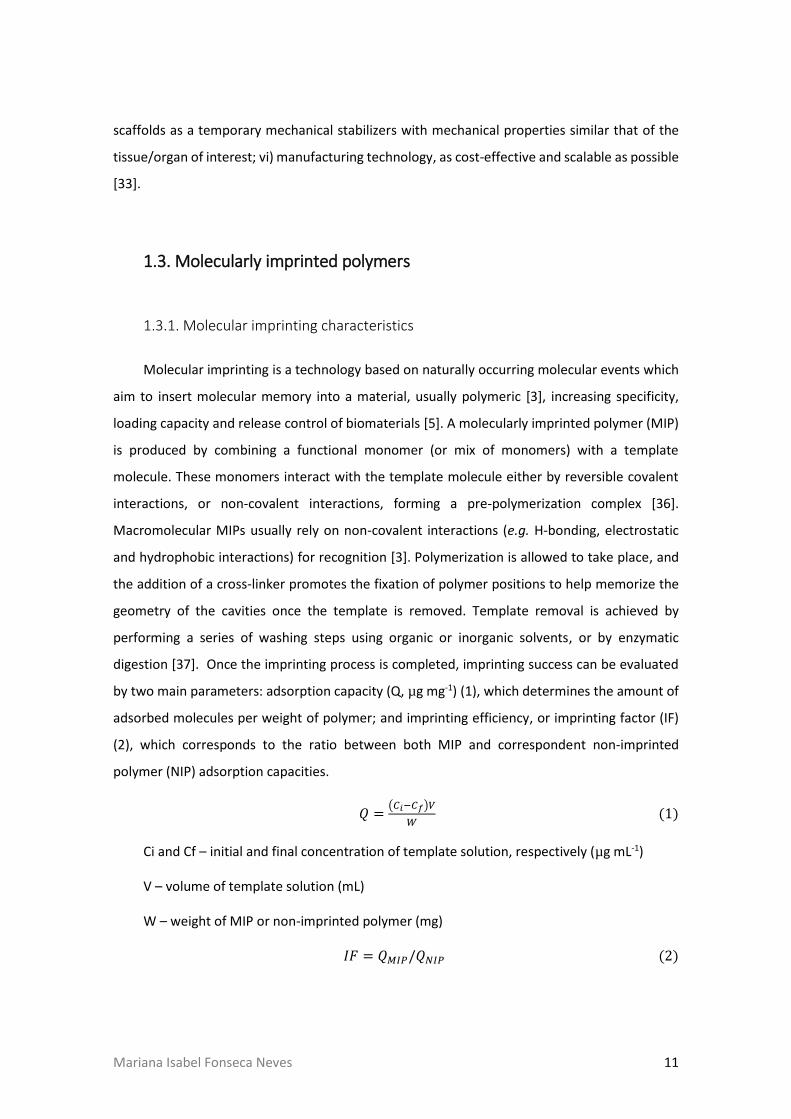
by two main parameters: adsorption capacity (Q, µg mg-1) (1), which determines the amount of
adsorbed molecules per weight of polymer; and imprinting efficiency, or imprinting factor (IF)
(2), which corresponds to the ratio between both MIP and correspondent non-imprinted
polymer (NIP) adsorption capacities.
𝑄 =(𝐶𝑖−𝐶𝑓)𝑉
𝑊 (1)
Ci and Cf – initial and final concentration of template solution, respectively (µg mL-1)
V – volume of template solution (mL)
W – weight of MIP or non-imprinted polymer (mg)
𝐼𝐹 = 𝑄𝑀𝐼𝑃/𝑄𝑁𝐼𝑃 (2)

12 Mariana Isabel Fonseca Neves
1.3.2. Molecular imprinting considerations
In order to create a material for TE applications, one should carefully mind several aspects
of MIP production. After choosing an appropriate template molecule, the choice of the
functional monomer(s) (and their ratios) bears great importance. The selected monomer(s)
should be biocompatible, nontoxic and have high affinity to the template so that template-
monomer complexes are thermodynamically favorable and stable under reaction conditions [3].
Since proteins contain many different binding sites and heterogeneous regions, the choice of
the polymer matrix will influence MIP selectivity by enabling or preventing cross-reactivity with
proteins similar to the template molecule [38]. For instance, it is not desirable for the polymer
to reactively polymerize with the template, a phenomenon frequently observed while
imprinting biomolecules into polyurethanes, where one of the monomeric units is an
isothiocyanate, capable of reacting with alcohol or amine groups present in most biomolecules
[2]. On the other hand, heteropolymer systems seem to favor macromolecular memory [5, 12,
39]. This can be explained by the conjugation of their different functional groups, thereby
increasing the number of available interaction sites with the different regions of the template
and improving their physico-chemical properties [12, 13]. Another possibility is the use of
natural ligand derivatives as functional monomers for the polymer matrix. Chou et al. [40]
produced a C-reactive protein imprinted polymer using a phosphorylcholine derivative (4NPPC)
as the functional monomer and the micro-contact approach. This approach uses a monolayer of
a minimal protein mass to which the recognition substrate will form an imprint [40]. The
resulting MIP showed rebinding capacity and selectivity towards the C-reactive protein, leading
the authors to conclude that the proposed micro-contact approach is a suitable method to
produce protein MIPs [40]. The MIP should be biodegradable to promote its replacement by the
natural ECM, but stable to withstand the harsh environmental body conditions. Biodegradability
is also important to allow exposure of new binding sites, especially in bulk imprinted materials.
MIP biodegradability, as well as flexibility, can be controlled by the degree and type of
crosslinking used. Higher degrees of crosslinking can promote higher selectivity by reducing
movement (e.g. swelling) and fixating binding sites [1]. However, an excessive degree of
crosslinking interactions can result in difficulties during template removal, and reduce rebinding
capacity due to impaired diffusion [41]. Despite existing covalent and non-covalent crosslinking
techniques used for MIP production, biological applications of MIPs prefer non-covalent
techniques due to more mild template removal methods [1].

Mariana Isabel Fonseca Neves 13
Molecular imprinting conditions should be mild in order to avoid protein denaturation or
polymer distortion. Biomacromolecules have complex structures that are highly sensitive to pH,
ionic strength, temperature and solvents [6]. If imprinting conditions are non-physiological,
changes in the natural conformation of the protein may result in imprinting cavities specific for
this altered form [3]. Kryscio et al. [42] performed an elaborate study on how different functional
monomers (acrylamide, methacrylic acid, acrylic acid, 3-aminophenylboronic acid and N-
isopropyl acrylamide) and crosslinkers (N,N’-methylenebisacrylamide and ethylene glycol
dimethacrylate) widely used in MI influence protein template conformational stability. The
authors used circular dichroism studies to analyze conformational changes in bovine serum
albumin (BSA), and concluded that these reactants induced significant changes in the secondary
structure of the template protein. This is a severe matter of concern as it can explain the low
rate of success of macromolecular imprinting [42].
The choice of the polymerization solvent brings challenges when it comes to protein
solubility [2]. While proteins are usually more soluble and stable in aqueous solutions, these
types of solvents are far from ideal as they affect the pre-polymerization complex by interfering
with hydrogen bonding (an extremely important type of interaction for many template-
monomer complexes) [3]. The solvent is responsible for mixing all of the components (i.e.,
template, functional monomer(s), crosslinkers and polymerization initiators) into one phase, in
addition to, creating pores in macroporous polymers [43]. Some studies on protein molecular
imprinting use organic solvents, such as chloroform [44], as they better stabilize the
polymerization process. However, for biomedical applications involving cell contact (i.e., drug
delivery and TE applications), these solvents must be avoided or replaced during MIP production
processes due to their high toxicity [45, 46].
During the imprinting of macromolecules, template removal is one of the critical phases
and consists on several washing steps using solvents, acids, bases, or detergents [2]. Other
possibilities include template removal by enzymatic digestion [37, 47]. Template removal is a
particularly delicate step during the imprinting process due to the large sizes of macromolecules.
Efficient template removal is often hard to obtain and still presents a major challenge when
imprinting large molecules. For each developed system, it is important to work on the
optimization of the template removal phase since it influences the final rebinding capacity and
success of the MIP. Hawkins et al. [47] optimized a template removal strategy for a bovine
hemoglobin (Hb) molecularly imprinted polyacrylamide gel using sodium dodecylsulphate (SDS)

14 Mariana Isabel Fonseca Neves
and acetic acid (AcOH). Even though a SDS:AcOH ratio of 10%(w/v):10%(v/v) did not present the
highest template removal percentage (only 47.6%), the highest imprinting efficiency (>90%) was
obtained. Higher template removal percentages can result in lower imprinting efficiencies if the
agents begin to promote conformational changes on the imprinting matrix [47]. The authors also
tested an enzymatic digestion-based template removal system with trypsin. This showed an
even higher template removal capacity (87.4%), compared to the SDS:AcOH maximum (71.5%),
but a significantly lower imprinting efficiency (20.4%). This can be a result of remaining protein
fragments inside the polymer matrix which may block potential binding sites [47]. On the other
hand, SDS can damage the cell membrane and lead to cell death. In BSA-imprinted hydrogel
films, even after several washing steps with deionized water, Zhao et al. [9] reported that SDS
remains a possible cause for total cell death of L929 cells after 5 days of culture. Optimization of
molecular imprinting systems should also focus on improving the wash steps needed for
template removal as the reagents can be toxic to cells.
Finally, depending on the final application of a MIP system, various polymerization
methods can also be applied. These methods include bulk suspension, two-step swelling,
precipitation, emulsion core-shell polymerization, film synthesis, aerosol polymerization and
polymerization on silica-beads [48]. Bulk polymerization is the most widely used method by
molecular imprinting groups, however it is used exclusively with organic solvents, and has the
disadvantage of wasting a significant percentage of polymer produced in the process of grinding
to obtain smaller irregular particles [48]. On the other hand, two-step polymerization requires
an aqueous polymerization medium and produces monodispersed particles with control of the
final size and number of particles [48]. Ideal molecular imprinting production methods should
be controllable and reproducible. For instance, Ying et al. [49] developed a gas jetting-dropping
method to produce beads of a controllable diameter in aqueous medium at a constant rate of
production (600 mL/h). This possibility is very important when it comes to industrial applications
for MIP materials.
1.3.3. Molecularly imprinted intelligent scaffolds
Molecular Imprinting can be a powerful tool used to create scaffolds with high bioactivity
and recognition capacity to specific molecules. Recognition, neutralization and clearance of
target peptides, such as toxin melittin, in the bloodstream has been achieved in vivo using

Mariana Isabel Fonseca Neves 15
molecularly imprinted polymeric nanoparticles with binding affinity and selectivity comparable
to that of natural antibodies [50]. Similarly, molecular imprinting can be applied during the
construction of TE scaffolds with the ability to recognize and adsorb a biomolecule transported
through the bloodstream, or present in situ, for ultimately promoting cell recruitment to the site
of injury or to trigger specific cell behaviors.
For TE applications, biomacromolecules bear great relevance due to their involvement in
the healing process. Increasing interest on the imprinting of macromolecules to exploit its
potential for clinical and pharmaceutical applications has driven many research groups to
develop protein MIP systems. The majority of protein MIP studies are usually developed for
model macromolecules like lysozyme (Lyz), BSA and Hb. However, few studies use biomolecules
of interest for TE technologies such as fibronectin (Fn). Fn, a high molecular weight protein
(composed of two polypeptides of molecular ~220 kDa each) with adhesive activity, is present
in the ECM and involved in several biological events, including wound healing and tissue repair
[51]. Recent advancements in the protein molecular imprinting field can strongly impact
regenerative medicine technologies through the use of molecular imprinted intelligent scaffolds
[52].
Figure 2. Molecular imprinting strategies for macromolecules. Molecular imprinting approaches can be divided according to the imprinted substrate they produce: bulk imprinting involves creating imprinting cavities in a material, namely in its inner layers (bulk); particle imprinting is based on the direct production of embedded- or surface-imprinted nano/microparticles; surface imprinting creates scaffolds which are only imprinted at the surface, or at the layers near it. Additionally, molecular imprinting approaches can be divided according to the type of template used, namely, in protein imprinting when the whole protein is used as a template, or in epitope imprinting when only relevant portions or domains of the molecule of interest are used.

16 Mariana Isabel Fonseca Neves
Many imprinting strategies exist, although majority are successful when imprinting small
molecules, but present several challenges for use with larger molecules such as proteins. Fig. 2
represents the main molecular imprinting strategies for macromolecules divided into two
categories: namely, according to either the substrate, or template type used.
1.3.3.4. Molecular imprinting mechanisms
Molecular Imprinting approaches can be classified according to the substrate imprinted
and further sub-divided into bulk, particle or surface imprinting. Bulk imprinting is a rather
successful strategy used for small molecules which involves imprinting cavities in the inner layers
of a polymeric material. However, this strategy presents some challenges when addressing mass
transfer, associated with the size of macromolecules. Usually, macromolecularly imprinted
materials produced by this approach strongly retain their templates and require extensive
grinding and sieving. This process to produces irregularly shaped polydisperse particles and
shorter lengths of diffusional pathways [6, 53]. For protein MIP strategies, particle-based
imprinting and surface imprinting are more commonly used. These are some of the most
successful because they reduce the diffusion pathway length, promoting protein movement
inside-out and outside-in. Not only does this lead to successful removal of the template and
increasing the number of available binding sites, but also promotes protein rebinding by
facilitating diffusion of proteins through the imprinted material. Particle-based strategies use
polymerization methods, such as emulsion or suspension, to directly synthetize micro-
/nanoparticles with the advantage of using lower quantities of monomers and template
molecules [3]. However, this presents the drawback of using stabilizers and surfactants (which
may cause the disruption of monomer-template complexes), since residual levels of stabilizers
remain even after an extensive washing process [3]. Surface imprinting is the most common
approach for protein MIPs, and consists of imprinting binding sites only at the surface or on the
superficial layers. This approach is similar to bulk imprinting, with the difference being that
surface imprinting is applied on thin films, or by attaching the protein on the surface of a
substrate [3]. In addition to alleviating macromolecule transfer, surface imprinting enables the
imprinting performance to be improved through the introduction of surface functional ligands.
These ligands allow for interaction with the template protein by reversible covalent binding or
affinity interactions, and by physical adsorption on the surface [54].
Mariana Isabel Fonseca Neves 17
An alternative way to address the classification of molecular Imprinting of macromolecules
is based on whether the whole protein is used during the imprinting process, or if only relevant
domains (epitopes) are used (Tab. 1). Epitopes are small domains or sequences exposed in
macromolecules that can be recognized by their receptors. Epitope imprinting uses small
protein domains or sequences, as opposed to the whole protein, to create materials with
molecular recognition towards proteins. This approach aims to overcome obstacles inherent to
protein imprinting caused by size complexity, and conformational characteristics of proteins [3].
In the same way, a MIP can recognize a whole protein if previously imprinted with its epitope.
Since these sequences can be synthetically produced, this approach also overcomes difficulties
associated with obtaining pure template proteins [53]. Additionally, epitope imprinting can
create highly selective scaffolds as reported by Zhao et al. [55] who developed Fe3O4 silica coated
nanoparticles with high adsorption rates and high selectivity towards BSA by using a BSA-specific
nonapeptide C-terminal amino-acid sequence as a template. The authors reported these MIPs
to have low tolerance for single amino acid mismatch since a significant reduction of imprinting
factor values were observed in MIPs imprinted with mismatched sequences of BSA, compared
to MIPs imprinted with the original sequence [55]. The authors also reported better recognition
features on epitope imprinted particles when compared to BSA imprinted particles [55]. This
supports the idea that molecular imprinting can be used to create highly specific and selective
systems at a sequence level.
Papaioannou et al. [56] reported promising results regarding epitope imprinting by
producing a MIP for RGD (Arg-Gly-Asp tripeptide) recognition, based on non-covalent
interactions. The RGD domain is known to be responsible for Fn adhesive activity [51]. RGD and
Fn are frequently used to functionalize different types of substrates (e.g. alginate) to promote
desirable cellular responses, either alone, or in combination with other bioactive molecules or
sequences [57, 58]. This approach could be applied to several other biologically relevant
domains or sequences. For instance, different domains of neural cell adhesion molecules (e.g.
fibronectin type III motifs FGL and BCL) have been proven to interact with fibroblast growth
factor (FGF) receptors, inducing neurite outgrowth in primary cerebellar granule neurons,
promoting synaptogenesis and enhancing presynaptic function [63]. Wang et al. [64] produced
a self-assembling RADA16 peptide nanofiber hydrogel functionalized with FGL enabling it to
promote spinal cord-derived neural stem cell proliferation and migration into the three-
dimensional scaffold. These and other biologically relevant motifs, could be imprinted in a

18 Mariana Isabel Fonseca Neves
Table 1. Recently developed systems on epitope imprinting of biomolecules.
Template Functional
Monomer(s) Crosslinker
Solvents / Template
removal agents Competitors Observations Ref.
RGD MAA AAm
TRIM MBAm EGDMA
Methanol / Methanol,
AcOH
KGD, CCK-3 and CCK5 peptides,
gramicidin
Production of polymers with different combinations of functional monomer and crosslinker. Higher IF and % net rebinding with MAA and TRIM. Selectivity achieved.
[56]
ANP MAA
NIPAm MBAm SDS / AcOH
BSA, scrambled
ANP
MIPs presented higher adsorption capacity than NIPs nanoparticles. Selectivity achieved. MIP recognition capacity tested and verified in cell cultured media spiked with ANP.
[59]
IgG Fab
fragment MAH MBAm DW
BSA, Fc fragment,
IgG
Production of monolithic cryogels with direct and Cu(II) assisted MAH. Effect of pH, template concentration, temperature and flow rate on adsorption capacity was analyzed. MAH[Cu(II)]-assisted MIP with higher adsorption capacity. Selectivity achieved.
[60]
PPA EGMPA PEGDA, MBAm
DW / MeCN, NaOH,
methanol BA, DPP
Ti4+-immobilized EGMPA. Higher adsorption capacity of MIPs than NIPs. Selectivity and regeneration achieved.
[61]
BSA C-terminal
nonapeptide
APTES TEOS
Methanol-MeCN-highly
purified water, PBS / Methanol,
AcOH
BHb, Cyt, HRP, Lyz
Fe3O4-silica coated nanoparticles. Better performance of epitope-imprinted than BSA-imprinted. Selectivity achieved at an amino acid sequence level. Good reusability performance.
[55]
ʟ-Lysine MAsp HEMA
PVA DW, SDS, NaHCO3 / DW, EtOH
HSA, Hb
Production of poly(HEMA-MASp) monodisperse imprinted nanoparticles. Recognition of IgG through Fc fragment obtained. IgG orientation preserved upon recognition. Selectivity achieved. Effect of pH on IgG adsorption analyzed. Good reusability performance.
[62]
AAm – acrylamide; AcOH – acetic acid; ANP – atrial natriuretic peptide; APTES – 3-aminopropyl triethoxysilicane; BA – benzoic acid; BHb – bovine hemoglobin; BSA – bovine serum albumin; Cyt – cytochrome c; DPP – diphenyl phosphate; DW – deionized water; EGDMA –ethylene glycol dimethacrylate; EGMPA – ethylene glycol methacrylate phosphate; HEMA – hydroxyethyl methacrylate; HRP – horseradish peroxidase; HSA – human serum albumin; IF – imprinting factor; Lyz – lysozyme; MAA – methacrylic acid; MAsp –N-methacryolyl-(ʟ)-aspartic acid; MBAm – N,N’-methylenebisacrylamide; MAH – N-methacryoyl-ʟ-histidine; MeCN – acetonitrile; NIPAm – N-isopropylacrylamide; PBS – phosphate buffered saline; PPA – phenylphosphonic acid; PEGDA – poly(ethylene glycol) diacrylate; PVA – poly(vinyl alcohol); RGD – Arg-Gly-Asp tripeptide; SDS – sodium dodecyl sulfate; TEOS – tetraethoxysilicane; TRIM – trimethylpropane trimethacrylate.
Mariana Isabel Fonseca Neves 19
biocompatible polymer scaffold to promote molecular recognition and desired cell functions.
High protein adsorption rates can occur in a biomaterial without any significant outcomes if
proteins undergo conformational changes, or hide relevant functional groups upon adsorption,
preventing cell adhesion to the scaffold. Using anti-BMP-2, a monoclonal antibody against bone
morphogenetic protein 2 (a protein known to promote the osteodifferentiation of progenitor
cells), Ansari et al. [65] reported the influence of orientation during protein immobilization
(without imprinting) in scaffolds for bone repair. While using Protein G as a linker to immobilize
the antibody through its Fc fragment on a collagen scaffold, the authors were able to achieve
higher antibody binding to cells concomitant with increased bone formation in vivo, compared
to passively adsorbing anti-BMP-2 antibodies to the same scaffolds [65]. This enhanced
performance can be explained by the increase in the number of available binding sites for the
anti-BMP-2 antibody to interact with its ligand. Protein orientation control has been achieved
by epitope imprinting of L-lysine residues, typical of C-terminus of immunoglobulin G Fc
fragment in poly(hydroxyethyl methacrylate-N-methacryolyl-(ʟ)-aspartic acid) nanoparticles
[62]. Corman et al. [62] reported higher human serum albumin (HSA) adsorption in particles
previously imprinted with L-lysine residues and exposed to anti-HSA antibodies, when compared
to non-imprinted nanoparticles, to which the antibodies randomly adsorbed. Molecular
imprinting can therefore be a suitable strategy for the production of scaffolds with enhanced
bioactivity consequent of an effective protein orientation upon adsorption, which will ultimately
promote cell adhesion and behavior at the site of injury due to the existence of increased binding
domains available.
One methodology which could further amplify potential applications of molecular
imprinting are post-imprinting modifications (PIMs), by allowing the modulation of on/off
switching of the molecular recognition, or the introduction of other desirable functions (such as
transduction of binding events into fluorescence events) [66, 67]. PIMs can be used to improve
imprinting features by the transformation of binding sites as reported by Taguchi et al. [37], who
produced thin films with the ability to molecularly recognize cytochrome-c (Cyt) by generating
peptide-fragment binding sites inside imprinted cavities. This was possible by using enzymatic
digestion as the template removal strategy, where pepsin would digest Cyt at specific sites,
leaving behind lysine residues grafted to the polymer backbone [37]. The authors reported high
selectivity of these scaffolds towards Cyt as only enzyme-accessible regions of MIPs can be

20 Mariana Isabel Fonseca Neves
transformed into protein-binding cavities, reducing the possibility of non-specific binding sites
commonly left behind by other conventional removal processes [37].
1.4. Hydrogels for macromolecular imprinting
The use of hydrogels constitutes another promising approach to overcome molecular
imprinting problems related to mass transfer of high molecular weight templates, and provide
the additional possibility of creating sensitive systems which respond to external stimuli [5, 6].
Hydrogels have been widely explored for biomedical applications, including TE, due to their
natural similarity to the ECM. Hydrogels are commonly used as drug carriers in pharmaceutical
applications, and are useful tools to create controlled release systems.
Hydrogels are polymeric networks with high hydrophilicity, i.e., they can absorb
considerably high amounts of water, expanding their volume and promoting diffusion within
their bulk [68]. They can be produced from natural or synthetic polymers, are chemically stable,
have biodegradable capabilities, and perform interactions which are reversible, depending on
the external stimuli applied (e.g. pH or temperature) [68]. Additionally, they can be processed
to acquire different forms (e.g. coatings, capsules, microspheres, tubes or sheets) and
functionalizations [58, 68], in order to improve their bioactivity.
Figure 3. Molecular structure of alginate and chitosan building blocks.
Molecular imprinting within hydrogels may be more challenging than in rigid structures,
owing to their inherent movement capacity [5]. Hydrogels can either expand or collapse easily,
Mariana Isabel Fonseca Neves 21
deeply affecting the imprinting efficiency by distortion of binding sites. So far, most studies using
molecular imprinting in hydrogels are intended to develop drug delivery systems with high
loading capacity and to improve controlled release [1, 5]. Nevertheless, several considerations
are taken into account for these systems and can be applied for TE applications. This section will
be focused on molecular imprinting using natural functional monomers, namely alginate and
chitosan (Fig. 3), due to their common use and great potential in TE applications.
1.4.1. Alginates and alginate composite polymeric hydrogels
Molecular imprinting studies in alginate hydrogels have been performed using Fn and the
model protein BSA (Tab. 2). Alginates are water soluble linear polysaccharides derived from
brown seaweed, composed of alternating blocks of 1-4 linked α-L-guluronic and β-D-mannuronic
acid residues [69]. Along with their great biocompatibility and biodegradability, alginates have
the ability to form gels with good mechanical properties by reacting with divalent cations [69].
Alginates enable the production of various platforms for biomedical applications [70], including
the development of alginate microspheres for growth factor delivery, such as bioactive VEGF to
promote osteogenic differentiation [71].
Significant work using sodium alginate as a functional monomer to create BSA-MIP has
been performed by Zhao and co-workers [9, 44, 72-75]. This group uses an inverse suspension-
method and ionic gelation to develop MIPs under mild conditions to avoid protein denaturation.
Furthermore, Zhao and co-workers frequently conjugate alginate with phosphate groups by
adding diammonium phosphate [(NH4)2HPO4, DAP], creating composite hydrogels with
improved imprinting features [44, 72, 74, 75]. The addition of phosphates into alginate matrices
combines the functionality of organic compounds with the stability of inorganic compounds [72].
In addition to developing heteropolymeric systems based on both natural and synthetic
polymers (where alginate is combined with acrylamide (AAm) and sodium polyacrylate [9, 73-
75]) to improve mechanical and imprinting properties of the final MIP, the group has developed
MIPs fully based on synthetic polymers [76]. Throughout some of these studies [44, 72, 74, 75],
the authors compared imprinting parameters (adsorption capacity and imprinting effect) of

22 Mariana Isabel Fonseca Neves
Table 2. Molecularly imprinted polymers (MIPs) developed with natural polymers, namely alginate, chitosan, and other synthetic polymers.
Template Functional
Monomer(s) Crosslinker
Solvents / Template Removal
Agents
Competitor
(s) Observations Ref.
Hb CS, AAm MBAm Sodium phosphate buffer /
SDS, AcOH BSA
Macroporous CS beads used as a matrix to improve mechanical and chemical properties of polyacrylamide as this latter polymer would fill the macroporous of the beads, forming a two-phase structure. Adsorption dynamic curve shows an initial rapid adsorption of Hb to MIPs, followed by a plateau where adsorption is slowed down, indicating rapid protein adsorption onto the surface at the beginning that difficults further Hb penetration into the bead. Selectivity tests performed with BSA showed high selectivity of the MIPs towards Hb. Good stability and reproducibility of the MIP were achieved.
[12]
Hb CS, Am MBAm Sodium phosphate buffer /
SDS, AcOH BSA
Phase-inversion method. Chitosan beads primarily produced as in [12]. A graft-MIPs was produced by graft copolymerization of CS beads and AAm. Adsorption patterns of Hb similar to the ones obtained in [12]. Selectivity tests performed with BSA showed high selectivity of the MIPs towards Hb. Good stability and reproducibility of the MIPs achieved.
[13]
Hb CS, Am MBAm Sodium phosphate buffer /
SDS, AcOH BSA
Comparison between MIPs produced similarly to [12] and [13]. graft-MIPs showed better adsorption capacity but lower selectivity than MIPs alone towards the template Hb. The authors justified this by the fact that in graft-MIPs, PAAm chains grow vertically out of the surface of the CS beads (faster adsorption due to easier access to binding sites) but do not to stabilize their spatial shape, losing molecular memory.
[14]
Hb CS, Am MBAm Sodium phosphate buffer /
SDS, AcOH BSA
Hydrogels based on semi-interpenetrating polymer networks (MIH-s-IPNs) were produced with CS and PAAm to improve mechanical properties. MIH-s-IPNs contained high water content (~94%). MIH-s-IPNs adsorption capacity was significantly higher than MIPs composed of PAAm alone. Selectivity analysis showed that MIH-s-IPNs had high selectivity towards the template. Analysis of the effects of temperature on water retaining of the hydrogel carried.
[39]
Hb CS, AAm MBAm Phosphate buffer / SDS, AcOH BSA, My, α-C, Lyz CS-coated silica particles were used to covalently immobilize the template molecule while PAAm was used to perform the imprinting. Adsorption capacity of MIPs was lower than NIP but MIP presented higher selectivity both with single-compound and mixed solutions.
[77]
Ova SA, CS GTA Phosphate buffer / NaCl BSA, Hb, Lyz
SA coated Fe3O4 magnetic nanoparticles were produced with a CS imprinted shell. SA to CS mass ratio influenced the imprinting effect, with 1:2 exhibiting higher adsorption capacity and imprinting efficiency. MIPs presented high selectivity towards Ova and good reusability profile. Different MIPs were also produced using BSA, Hb and Lyz as template molecules and selectivity achieved.
[15]
BSA SA CaCl2 Chloroform, hexane, Span85
and Tween80 / DW
Production of SMIPMs and EMIPMs. DAP was introduced to add phosphate groups to the polymer matrix (composite microspheres). Qe and IE tested for different concentrations of DAP, CaCl2 and SA and optimum Qe results were obtained at 0.15% DAP, 5% CaCl2 and 2.5% SA for SMIPMs. Qe(SMIPMs)> Qe(EMIPMs) and IESMIPMs> IEEMIPMs.
[44]

23
BSA SA, SPA CaCl2 Castor oil, butyl acetate /
CaCl2, Tris-HCl buffer
Production of SMIPMs and EMIPMs. DAP was introduced to add phosphate groups to the polymer matrix (composite microspheres). Qe(SMIPMs)> Qe(EMIPMs) and IE(SMIPMs)> IE(EMIPMs) until 180 mins of rebinding time.
[74]
BSA SA CaCl2 Chloroform, hexane, Span85 and Tween80 / CaCl2,Tris-HCl
buffer Hb, Lyz, Glo, EAB
Production of SMIPMs and EMIPMs. DAP was introduced to add phosphate groups to the polymer matrix (composite microspheres). Qe(SMIPMs)> Qe(EMIPMs) and IESMIPMs> IEEMIPMs. Effect of CaCl2 and BSA concentrations and pH values on Qe and EI tested. MIP presented high selectivity towards BSA even though Lyz was also highly adsorbed due to smaller size which facilitated diffusion through the MIPs.
[72]
BSA SA, SPA CaCl2 Castor oil, butyl acetate
ethylic cellulose / CaCl2,Tris-HCl buffer
Lyz, Hb, Glo, EAB Production of multi-hybrid polymer microspheres. Qe and IE tested for different concentrations of CaCl2. MIPs presented higher adsorption capacity than NIP and selectivity towards BSA. Lyz was also highly adsorbed due to smaller size which facilitated diffusion through the MIPs.
[73]
BSA SA, SPA CaCl2 Castor oil, butyl acetate /
CaCl2,Tris-HCl buffer Hb, Lyz, EAB
Production of SMIPMs and EMIPMs. DAP was introduced to add phosphate groups to the polymer matrix (composite microspheres). Qe(EMIPMs)> Qe(SMIPMs) and IEEMIPMs> IESMIPMs IEEMIPMs. Qe and IE tested for different concentrations of CaCl2 and BSA and pH values.
[75]
BSA SA, AAm MBAm CaCl2
DW / HAc containing SDS Hb, Ova, Glo
Hydrogel film. Ionic crosslinking and covalent crosslinking. Different AAm/SA ratios (6:1, 8:1, 10:1 and 12:1) tested. Better Qe and IE at 6:1 ratio. Different MBAm and CaCl2 concentrations tested. Effect of thickness on imprinting performance tested. High adsorption capacity of MIPs was reduced with increasing thickness. Adhesion tests with mouse fibroblast cells (L929). MIPs promoted cell adhesion but residual SDS was believed to be the reason for cell death after 5 days of culture. Selectivity was achieved.
[9]
BSA SA CaCl2 DW / CaCl2, Tris-HCl buffer Ova
Description of gas jetting-dropping (GJD) method for production, with controlled dropping speed and droplet dimension as diameter and volume of alginate microspheres is indirectly proportional do nitrogen pressure. Smaller diameters can be achieved with GJD method that gravitational method but morphology can be affected at higher pressure levels. MIPs presented higher adsorption capacity than NIPs. Differences in diameters lead to differences in rebinding properties: smaller microspheres show better Qe and IE and selectivity increased with diameter of MIPs.
[49]
BSA SA, PU CaCl2 DW / CaCl2, Tris-HCl buffer Ova
2-step process where PU-grafted calcium alginate (PU-g-CA) hydrogel microspheres were initially produced, followed by an imprinting process which occurred under ionic gelation with CaCl2 to avoid protein denaturation. Grafting process improved mechanical strength of matrix and leads to rougher surface (comparing to calcium alginate beads). MIP presented higher adsorption capacity than NIPs. Rebinding capacity was seriously affected by pH of polymer assembly solutions and by external pH of template solution. Both BSA-MIPs Ova-MIPs were produced and selectivity was achieved.
[78]
BSA SA CaCl2 DW / CaCl2, Tris-HCl buffer Ova, HSA, Hb Production of hydrogel film by biocompatible gelation method in aqueous media, intended for biomedical applications. Higher adsorption capacity of MIPs achieved but no selectivity.
[79]
BSA SA CaCl2 DW / CaCl2, Tris-HCl buffer
Production of hydrogel microcapsules by biocompatible gelation method in aqueous media, intended for biomedical applications. Analysis of different template removal protocols on the percentage of recovered template and recognition capacity of the MIPs.
[80]
BSA SA CaCl2 GTA
DW / Tris-HCl buffer Production of semi-interpenetrating polymer networks containing SA and HEC to improve mechanical stability. Dual crosslinked microspheres presented lower water uptake over time. Adsorption capacity higher in SA/HEC microspheres than SA alone.
[81]

24 Mariana Isabel Fonseca Neves
Fn SA, AAm MBAm DW / Tris-HCl buffer
Non-woven PP fiber used as support for MIP. Lamellar macroporous structure at the surface which facilitated diffusion of template. Fn adsorption 2.6 times higher on MIP than NIP. Cell adhesion tests were performed with L929 cells. Higher cell adhesion rates and higher number of living cells on MIP than NIP. Cell morphology analysis showed cell spreading on MIP surface.
[82]
BSA NIPA, [VAFMIM]Cl MBAm Tris-HCl buffer / NaCl solution Ova, Lyz, Hb
Thermosensitive hydrogel system capable of reversible volume transition between shrinking and swelling according external stimuli. Effects of two different drying methods in morphology and mechanical properties analysed. Analysis of the effect of functional monomer on BSA stability. Analysis of the influence of BSA, [VAFMIM]Cl and MBA in recognition capacity. Higher adsorption capacity of MIPs than NIPs. Selectivity achieved.
[83]
BSA AAm MBAm DW / SDS, AcOH Hb, Ova, Glo, Lyz
Production of hydrogel membrane using non-woven PP fiber. UV radiation-reduced graft polymerization. Effect of monomer concentration, cross-linker concentration, amount of template molecule and pH in BSA solution on Qe and IE tested. Higher adsorption capacity of PP-grafted-PAAm-MIPs than NIPs and improved regeneration properties than PAAm-MIP beads. Selectivity achieved.
[76]
Hb AAm MBAm Phosphate buffer / SDS, AcOH Lyz, EAB, Pep, Pap,
Try
Silica coated magnetic (Fe3O4) nanospheres functionalized with MAPS to add vinyl groups served as substrate for the imprinting process. Higher adsorption capacity of MIPs than NIPs. Selectivity achieved. Good regeneration and reproducibility features.
[84]
BSA AAm MBAm Phosphate buffer / SDS, AcOH Lyz, Lac, Glo Higher adsorption capacity of MIPs than NIPs. Analysis of the influence of crosslinking density, polymerizing temperature, protein type and BSA amount on imprinting efficiency. Selectivity analyzed and achieved for BSA-MIPs. Regeneration was not achieved.
[85]
Hb AAm MBAm RO water / SDS, AcOH or
Trypsin solution Cyt, Myo
Higher adsorption capacity of MIPs than NIPs. Different template removal strategies analyzed, including varying ratios of SDS:AcOH and enzymatic digestion with trypsin. Optimum ratio SDS:AcOH at 10%(w/v):10%(v/v) with 48% template removal and more than 90% imprinting efficiency. Trypsin treatment achieved high template removal (up to 84%) but low imprinting efficiency (20%). Selectivity achieved.
[47]
Lyz AAm MAA
MBAm Tris buffer / DW, NaCl
solution Cyt, BSA
Different ratios of crosslinker, PAAm and MAA analyzed. Effect of NaCl on binding activity towards the template.
[41]
AA – acrylic acid; AAm – acrylamide; AcOH – acetic acid; AMPS – 2-acrylamido-2-methyl-propanosulfonic acid; APTES – 3-aminopropyl triethoxysilane; BSA – bovine serum albumin; CaCl2 – calcium chloride; CS – chitosan; Cyt – cytochrome c; DAP – Diammonium phosphate (NH4)2HPO4; DW – deionized water; EAB – egg albumin; ECH – ephichlorohydrin; EMIPMs – embedded molecularly imprinted polymer microspheres; Fn – fibronectin; Glo – γ-globulin; HAc – anhydrous acetic acid; Hb – hemoglobin; HSA – human serum albumin; g-MIP – grafted-molecularly imprinted polymer; HEC – hydroxyethyl cellulose; HSA – human serum albumin; Lac – α-lactalbumin; Lyz – lysozyme; MAA – methacrylic acid; MAH – maleic anhydride; MAPS – 3-methacryloxypropyl trimethoxysilane; MBAm – N,N’-methylenebisacrylamide; MIP – molecularly imprinted polymer; Myo – myoglobulin; NIP – non-molecularly imprinted polymer; NIPA – N-isopropylacrylamide; Ova - ovalbumin; PAAm – poly(acrylamide); Pap – papain; Pep – pepsin; PP – polypropylene; PU – polyurethane; SA – sodium algiante; SDS – sodium dodecyl sulfate; SMIPMs – surface molecularly imprinted polymer microspheres; SPA – sodium polyacrylate; TEOS – tetraethoxysilicane; Try – trypsin; [VAF- MIM]Cl – 1-vinyl-3-aminoformylmethyl imidazolium chloride.

Mariana Isabel Fonseca Neves 25
alginate embedded MIP microspheres (EMIPMs) and surface MIP microspheres (SMIPMs) using
BSA as the template molecule. Preparation methods for these approaches differ on the timing
and the amount of template added. Despite SMIPMs requiring lower template concentrations
during the molecular imprinting process, the microspheres usually present increased imprinting
performance compared to EMIPMs [44, 72, 74, 75]. This is easily explained since EMIPMs face
mass transfer problems inherent to bulk imprinted approaches. A practical application of these
natural polymer-based microspheres is as building blocks for TE scaffolds, specifically in bottom-
up approaches, to improve protein loading within the scaffold [86]. As the majority of template
molecules of interest for TE applications are expensive and difficult to obtain in high rates of
purification, it is important to mind cost/efficiency ratio, which will dictate production viability
and market diffusion of any biomedical product.
A problem encountered by many of the previously cited works is the use of cytotoxic
compounds as solvents or template removal agents (e.g. SDS) which may impair the application
of these systems for TE. However, the development of more biocompatible systems for
biomedical and food industry applications is the subject of continuing research. Peppas and co-
workers [79, 80] have developed molecular imprinting methodologies for biomedical purposes
using alginate and calcium chloride. Herrero et al. [80] developed a biocompatible system with
the ability to achieve 3.0 mg of BSA per gram of capsules, compared to 0.7 mg achieved via
inverse suspension by Zhao et al. [72], without using any chemicals besides sodium alginate and
calcium chloride. These results are promising and are the first steps towards optimization of
protein molecular imprinting systems for delivery and implantation in the human body.
The potential of alginate imprinted systems for generating platforms for cell culture studies
has been previously investigated. Zhu et al. [82] recently created a Fn-imprinted
alginate/polyacrylamide (PAAm) hydrogel, supported by a polypropylene non-woven scaffold,
which promoted Fn adsorption in addition to adhesion and spreading of mouse fibroblast cells
(L929). The combination of more than one functional monomer is a widely used methodology
to improve imprinting efficiency. This increases the number of potential binding sites available
for the template, and improves physical and chemical characteristics (e.g. swelling behavior or
mechanical stability) of molecularly imprinted hydrogels. In this particular case of
alginate/PAAm, an improvement in mechanical and elastic properties of the combined polymer
systems was reported [87]. Alginate/PAAm scaffolds have also proven to be suitable platforms
to support human stem cell proliferation and chondrogenesis [87]. An additional study, also

26 Mariana Isabel Fonseca Neves
based on the imprinting of Fn, was developed by Fukazawa et al. [88] who created a Fn-MIP
system based on a water soluble biocompatible phospholipid polymer constituted by 2-
methacryloyloxyethyl phosphorylcholine (MPC). MPC is a biocompatible polymer unfavorable
for protein adsorption, thus frequently used as a coating to achieve antithrombogenicity for
medical devices [88]. Using silica beads with adsorbed Fn to create protein stamps, cavities with
high selectivity to Fn were imprinted on the polymer, creating a cell capturing system with low
rates of nonspecific adsorption [88]. Cell adhesion tests performed with L929 cells, the authors
proved that cells only adhered in the bead cavities where Fn had been imprinted, and not on
the surface of the non-imprinted polymer (NIP). This approach has the potential to be applied
as a cell patterning technique by designing scaffolds with precise control of local cell adhesion
[89].
1.4.2. Chitosan and chitosan composite hydrogels
Another widely used polymer is chitosan, a natural polysaccharide obtained from the
deacetylation of chitin from the exoskeleton of crustaceans. It has been widely explored for
biomedical applications due to its abundant source, biocompatibility and biodegradability [90].
Chitosan amino and hydroxyl groups make it possible to interact with different protein regions
through van der Waals interactions, hydrogen bonding and hydrophobic interactions [90].
Chitosan has already been used as a functional monomer for molecular imprinting of low
molecular weight molecules such as dye adsorption, enantioselective separation of amino acids,
metal ions removal in decontamination activities, and some chemical/pharmaceutical
applications [91-96]. A MIP sensitive system was reported by Singh et al. [92] who created a
hydrogel system sensitive to pH, temperature and ionic strength with molecular recognition to
carnosine, a dipeptide highly concentrated in muscle and brain tissues with reported antioxidant
properties [92]. However, for macromolecular imprinting, most studies performed with chitosan
combine this polymer with synthetic monomers (e.g. PAAm or 2-hydroxyethyl methacrylate) or
use modified chitosan (Tab. 2).
Chitosan is commonly used to improve mechanical properties of other polymeric materials
during the molecular imprinting processes. Guo and co-workers [12-14, 39, 77] developed
several studies focusing on chitosan-based matrices for Hb recognition for biosensing
applications. In most of these studies, chitosan is combined with epichlorhydrin, a water soluble

Mariana Isabel Fonseca Neves 27
crosslinker that preserves the cationic amine function of chitosan and improves its wet strength,
to produce beads which are used as a matrix for acrylamide monomers during the molecular
imprinting process [12-14]. Guo et al. [13] reported a chemical modification of porous chitosan
beads by adding maleic anhydride groups to improve chitosan bonding to AAm. This
modification increased vertical growth of PAAm chains from the surface of the beads, leading to
higher protein adsorption rates, but lower selectivity towards the template molecule since the
geometry of cavities could not be successfully preserved [13]. Later, Xia et al. [39] developed a
Hb-imprinted semi-interpenetrating polymer network in an aqueous medium by combining
chitosan and AAm. The MIP produced revealed high capacity to retain water, and higher
adsorption and selectivity when compared to molecular imprinting hydrogels made only of
PAAm [39]. Nevertheless, there is evidence of significant non-specific binding of imprinted
chitosan/PAAm polymers [97]. Fu et al. [97] analyzed different conditions where BSA and Hb-
imprinted polymers showed increased recognition when compared to non-imprinted polymers,
but in much higher quantities than those used as a template during MIP synthesis. This behavior
was hardly explained, since the yield in binding sites relative to the amount of imprinting
molecule should be low [97]. When washing non-imprinted polymers the same way as MIPs (i.e.,
including template removal solutions), the authors found that NIPs presented an increase in
protein binding which was comparable to MIPs [97]. Therefore, all procedures, with the
exception of template addition, should be equally performed on the controls as they are for
imprinted polymers in order to assure chemical changes promoted by solvents are taken into
account when both materials are compared. Very few studies are performed solely on AAm as
a functional monomer [47, 85] despite its great biocompatibility. Combining AAm with other
functional monomers has been shown to improve mechanical properties and imprinting
features of the matrix when comparing separate functional monomers [9, 12-14, 39].
Dan et al. [90] studied different copolymerization systems for chitosan and other synthetic
polymers at different pH values and temperatures for the recognition of ovalbumin. Copolymers
composed of chitosan and methacrylic acid showed increased imprinting features and selectivity
at different pH and temperature levels [90]. Gao et al. [15] recently reported a MIP system
conjugated with alginate and chitosan to improve imprinting features of a magnetite (Fe3O4)
nanoparticles-based system for molecular recognition of ovalbumin. With a two-step method,
the authors modified Fe3O4 nanoparticles with sodium alginate to attract chitosan onto the
surface (since these polysaccharides are oppositely charged) and promoted polymerization to

28 Mariana Isabel Fonseca Neves
create a molecularly imprinted shell around the particles. The imprinting effect was reported to
be dependent on the alginate to chitosan mass ratio, with 1:2 exhibiting the best adsorption
capacity and imprinting efficiency values towards ovalbumin [15]. The authors also showed that
this system was highly selective towards different template molecules, including ovalbumin,
BSA, Hb and Lyz [15]. The existence of oppositely charged functional groups, carboxyl and
hydroxyl groups from alginates, and amine groups from chitosan, may have promoted the
imprinting effect as they support interactions between the polymer matrix and the differently
charged domains of these proteins.
1.5. Cell imprinting
Molecular imprinting principles for macromolecules can be applied for the imprinting of
larger templates such as cells. Cell imprinting has been vaguely explored, but is based on the
imprinting of morphological and topographic features of cells to improve cell adhesion in/on a
substrate. To program mammalian cell adhesion and growth, DePorter et al. [98] proposed a
cell-imprinting approach to produce a culture system as an alternative to the conventional high
cost, multi-step fabrication processes. The authors successfully imprinted substrates by casting
a PAAm gel on pre-fixed (4% formaldehyde/PBS) monolayers of HeLa, HEK-293T (epithelial-like
cells) and MRC-9 (fibroblast-like cells) cells. Although cell viability was maintained, there is room
for improvement. Adhesion experiments revealed that HEK-293T and MRC-9 cells adhered
preferentially to epithelial-like imprinted surfaces, with MRC-9 cells losing their fibroblast-like
morphology features, and HeLa cells adhering to all imprinted-substrates [98]. Jeon et al. [99]
developed a PDMS imprinted surface using MG63 osteoblast-like cells (as a template) fixed with
glutaraldehyde at the proliferation stage. The group used an electric field assisted casting
method during different culturing times and showed that rough surfaces promoted cell viability
and increased alkaline phosphatase activity and mineralization [99].
Currently, cell imprinting is at its early stages, and more studies need to be performed to
further explore its applications and influences on various cell functions. Further investigation of
this topic would lead to an understanding if this technology is feasible and reproducible
compared to existing technologies for cell patterning and culturing.

Mariana Isabel Fonseca Neves 29
1.6. Future prospects for molecular imprinting
Molecular imprinting is a technology with the potential to be applied for biomedical
applications, such as tissue engineering. Even though little work has been developed on
biologically relevant macromolecules for TE applications, studies performed on model proteins
are a helpful platform to optimize molecular imprinting systems. One can expect molecular
imprinting technologies to evolve for more biocompatible production approaches, which will
enable cell growth and survival. Mild conditions to avoid protein denaturation are required
during molecular imprinting, and all cytotoxic components should be avoided without
compromising imprinting features, something already achieved. Additionally, more systematic
and reproducible technologies with greater control of imprinting parameters and molecularly
imprinted polymer (MIP) structure (e.g., beads diameter or porosity) will present greater
industrial viability. Once solved, these key aspects will undoubtedly catapult the use of
molecular imprinting with living organisms and biomedical applications. Some additional aspects
of biopolymer polymeric design have been recently discussed by Peppas and Clegg [100].
Molecular imprinting will especially be relevant for scaffold-based strategies (Fig. 4) as they
depend on scaffold bioactivity to modulate cell activity in situ. As previously mentioned,
scaffold-based approaches rely on the knowledge of the extracellular matrix as an important
source of signals to cells and the maintenance of ECM homeostasis. Developing a scaffold with
molecular recognition capabilities, enables MIP technologies to not only promote loading
capacity of MIPs, but to promote recognition of a specific molecule in a complex mixture of
biological compounds (a real scenario all implants face when introduced in the organism)
(Fig.4A). The latter option brings a new set of possibilities for scaffold-based strategies, since
the majority of conventional methods rely on the delivery of previously immobilized factors.
Besides poor loading capacity, these methods have therapeutic efficacy impaired as protein
conformation changes due to immobilization methods. Molecular imprinting systems can be
optimized to overcome these problems as research performed in the protein template area
proceeds. As adsorption capacity and selectivity are essential to dictate the success of a MIP-
based based technology, if any major conformational changes were to occur during the
production process, basic imprinting features would be compromised, and the MIP would
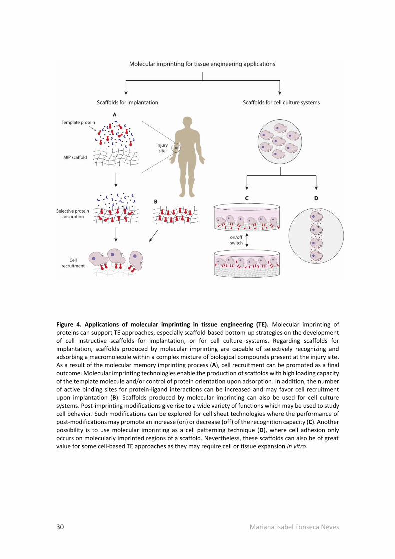
30 Mariana Isabel Fonseca Neves
Figure 4. Applications of molecular imprinting in tissue engineering (TE). Molecular imprinting of proteins can support TE approaches, especially scaffold-based bottom-up strategies on the development of cell instructive scaffolds for implantation, or for cell culture systems. Regarding scaffolds for implantation, scaffolds produced by molecular imprinting are capable of selectively recognizing and adsorbing a macromolecule within a complex mixture of biological compounds present at the injury site. As a result of the molecular memory imprinting process (A), cell recruitment can be promoted as a final outcome. Molecular imprinting technologies enable the production of scaffolds with high loading capacity of the template molecule and/or control of protein orientation upon adsorption. In addition, the number of active binding sites for protein-ligand interactions can be increased and may favor cell recruitment upon implantation (B). Scaffolds produced by molecular imprinting can also be used for cell culture systems. Post-imprinting modifications give rise to a wide variety of functions which may be used to study cell behavior. Such modifications can be explored for cell sheet technologies where the performance of post-modifications may promote an increase (on) or decrease (off) of the recognition capacity (C). Another possibility is to use molecular imprinting as a cell patterning technique (D), where cell adhesion only occurs on molecularly imprinted regions of a scaffold. Nevertheless, these scaffolds can also be of great value for some cell-based TE approaches as they may require cell or tissue expansion in vitro.
Mariana Isabel Fonseca Neves 31
present no major differences from a non-imprinted polymer. Epitope imprinting approaches can
also be an alternative to minimize these effects, as they are less prone to conformational
changes by their significantly lower complexity and size, with the additional advantage of
promoting correct protein orientation, thereby increasing scaffold bioactivity as more protein
binding sites are available for interaction with cell receptors (Fig. 4B).Several biomolecules can
be used as a template for developing scaffolds for regenerative medicine applications. Growth
inducing cytokines, peptides and proteins, including bone morphogenetic proteins (BMPs),
transforming growth factor beta (TGF-β), vascular growth factor (VEGF), fibroblast growth factor
(FGF), platelet derived growth factor (PDGF), insulin-like growth factor (IGF) and stromal derived
growth factor (SDF1) have generated interest by their roles in the wound healing processes.
Additionally, ECM molecules such as Fn can be successfully imprinted to promote cell adhesion
on/in scaffolds. Once molecularly imprinted with these molecules, scaffolds can be implanted at
the site of injury and adsorb the template molecule at higher rates than other compounds,
promoting cell binding to the adsorbed proteins, which will consequently lead to a specific
cellular response. MIPs have been shown to selectively adsorb template molecules when in a
complex solution and promote cell adhesion, prospecting the potential application for scaffolds
capable to attract the template molecule in situ and trigger a specific cell behavior. An
application of molecular imprinting for the near future will definitely go through cell culture
systems in vitro. Post-imprinting modifications allow further versatility of MIP scaffolds enabling
an on/off switch of the binding recognition, a feature which can be suitable for cell sheet
technologies (Fig. 4C). MIPs can also be considered for cell patterning techniques, as cell
adhesion can be controlled by the imprinted and non-imprinted regions (Fig. 4D).
Hydrogels present themselves as suitable solutions to overcome current drawbacks in
molecular imprinting of bio-macromolecules due to the inherent characteristics and tunable
mechanical and chemical properties of these biomaterials. Similarly to other functionalization
techniques, several natural and synthetic biomaterials, or their combinations, have been
characterized in the literature for the production of MIPs with promising results. The possibility
of utilizing different polymerization and production methods in mild and biocompatible
conditions (without compromising imprinting features) gives rise to the potential of developing
molecularly imprinted hydrogels on the design of highly precise bottom-up strategies for the
production of scaffolds with improved bioactivity.

32 Mariana Isabel Fonseca Neves
Another imprinting strategy is cell imprinting, a technology currently at its early stages, but
presents itself as a dauntless new perspective. Nevertheless, the imprinting of cells is an
untapped molecular imprinting approach which is the topic of continuing research.
Mariana Isabel Fonseca Neves 33
Chapter 2 Aim of the Project
The overall aim of the project presented herein was to develop and characterize an
alginate-based molecularly imprinted system for potential biomedical applications.
More precisely, this project intended to create a system based on photocrosslinkable
alginate discs for the recognition of the model protein bovine serum albumin. The choice of this
protein as the template is justified by the primary need to characterize and understand the
effect of particular parameters in this new system. For that purpose, the first specific objective
of this project was to develop and optimize a protocol to create a photocrosslinkable polymer
based on the modification of alginate, replacing its functional groups by photosensitive
methacrylate groups. Secondly, this project aimed at evaluating how this new material was
affected by different production parameters (UV exposure time and disc thickness) and external
stimuli (pH and presence or absence of salts) which could influence the molecular imprinting
process. To do so, molecularly imprinted polymers were produced and a template removal
protocol was optimized by adapting the effect of different variables of the system. Also, different
protein quantification methodologies were tested to evaluate the system.
Finally, the capacity of these discs to specifically recognize the template molecule was
evaluated by rebinding assays as a proof of concept.

34 Mariana Isabel Fonseca Neves
- This page was intentionally left in blank -

Mariana Isabel Fonseca Neves 35
Chapter 3 Materials and Methods
The principal objective of this project was the development of a molecular imprinting
protocol in a photosensitive alginate-based system. To accomplish this, different stages of the
production process had to be optimized according to different parameters (Fig. 5).
Figure 5. The four main stages of development of this project.
3.1. Alginate Methacrylation
Methacrylation of alginate was performed by replacement of hydroxyl groups by
methacrylate groups. A 1% w/v alginate (AL, PRONOVA UP MVG, 248.13 kDA, Novamatrix)
solution was produced by dissolving alginate in a Tris Buffered Saline (TBS, pH 8) solution.

36 Mariana Isabel Fonseca Neves
Alginate methacrylation was performed for 5, 10 or 24h by adding methacrylic anhydride (MA,
154.16 g/mol, Sigma-Aldrich, Fig. 6) to the alginate solution in a total proportion of 1 g AL/15 mL
MA (0.07 g/mL). MA additions were performed at three different timepoints (0, 1 and 3h or 0, 3
and 6h). The solution was maintained in ice and 5M NaOH (VWR) was added dropwise during
methacrylation to keep pH=8. The reaction between MA and the alginate solution is exothermic
and MA hydrolyzes at pH levels lower than 8 and high temperature. To stop the reaction 100%
EtOH (4ºC) was added in excess to promote polymer precipitation and the pellet was left to dry
overnight. Rehydration of the pellet was performed by adding deionized (DI) water under
magnetic agitation. Dialysis was performed against DI water for 3 days using dialysis membranes
(Spectra/Por 3 Dialysis, MWCO 3.5 kDa). After dialysis, the pH of methacrylated alginate (ALMA)
solutions was adjusted to 5 (ALMA 5) or 7 (ALMA 7) using HCl or NaOH solutions, respectively.
The final solutions were frozen at -20ºC and lyophilized (Virtris BenchTop Pro 9 L -85ºC, SP-
Scientific). All the procedure was performed protecting samples from light using aluminum foil.
Figure 6. Molecular structure of methacrylic anhydride [101].
3.2. 1H NMR analysis
Unmodified and methacrylated alginates ALMA 5 and ALMA 7 were dissolved in deuterium
oxide (D2O, Sigma-Aldrich) to produce a 1% w/v solution at 4ºC overnight. 5 µl of 3-
(trimethylsilyl)propionic-2,2,3,3-d4 acid sodium salt (TSP-d4, Euriso-top) were added to the
solution as internal standard. The 1H NMR spectra were recorded on a BRUKER AVANCE III (400
MHz, 9.4 Tesla) NMR spectrometer (CEMUP, University of Porto, Portugal). The degree of
methacrylation (DM) was calculated from 1H NMR spectra based on the ratio of the integrals
from the protons of alginate backbone to the protons of methacrylate compound. The final DM

Mariana Isabel Fonseca Neves 37
was determined as an average of ALMA 5 DM and ALMA 7 DM values determined by the
following equation (3)
𝐷𝑀 (%) =𝐴𝑣𝑒𝑟𝑎𝑔𝑒 (
𝐻𝑎3
+𝐻𝑏 + 𝐻𝑐
2)
𝐻𝐴𝐴6
(3)
3.3. Production of methacrylated alginate non-imprinted and molecularly
imprinted discs
Alginate discs were produced from methacrylated alginate ALMA 5 and ALMA 7 using
photo-polymerization with UV light. A 0.05% w/v photoinitiator solution was prepared by
dissolving 2-hydroxy-1-[4-(hydroxyethoxy)phenyl]-2-methyl-1-propanone (Irgacure 2959,
Sigma-Aldrich) in 0.9% NaCl at pH 4.2. Irgacure 2959 (Fig. 7) is a moderately water-soluble
photoinitiator and was selected for this protocol since it has been reported to cause minimal
cellular toxicity in a wide range of mammalian cell types and species [102], therefore being
suitable for biomedical applications.
Figure 7. Molecular structure of Irgacure 2959 [103].
To produce molecularly imprinted polymers (MIP), the template molecule, bovine serum
albumin (BSA, ~66 kDa, Sigma-Aldrich), was dissolved in 0.05% Irgacure solution to make a 1%
w/v BSA solution. To that solution enough alginate was added to make a 1.5% w/v polymer
solution and left mixing at room temperature for approximately 30mins. To produce discs
without the template, i.e., non-imprinted polymer (NIP) alginate discs, the same protocol was

38 Mariana Isabel Fonseca Neves
performed but no BSA was added to the initial Irgacure solution. 20µL of MIP or NIP solutions
were dispensed with a gel pipette to a TEFLON platform, covered with glass and exposed to UV
light adjusted to a light intensity of 7 mW/cm2 (320-395nm, BlueWave 200 Light-Curing Spot
Lamp, Dymax, adjusted using ACCU-CAL-30 Smart UV intensity Meter, Dymax) for 60 or 70s and
using 250, 500 or 750µm spacers (Fig. 8). This spacer-based methodology enables an easy
control of disc dimensions such as thickness and diameter, by varying the size of spacer used or
the volume of solution used.
Figure 8. Spacer-based approach used to produce methacrylated alginate discs.
3.4. Swelling behavior of alginate discs
In this project, the swelling capacity of methacrlyated alginate discs was evaluated at two
different stages using two different approaches.
3.4.1. Variation of disc diameter: in this approach, the swelling behavior was evaluated by
the diameter variation of discs incubated in solutions of varying composition and throughout

Mariana Isabel Fonseca Neves 39
certain timepoints. Briefly, ALMA 5 and ALMA 7 discs produced with 750µm spacers and
exposed to 60 or 70s of UV light were incubated in a 24-well plate for 3 cycles of 1h (RT) in 1mL
of a particular incubation solution: DI water (pH 5.6), 0.05M Tris HCl (pH 7.4), 0.05M Tris HCl
with 1% CaCl2 (pH 7.4) or 0.05M Tris HCl with 1% MgCl2 (pH 7.4). At the end 3h, the solution was
removed and changed to DI water and kept at 4ºC throughout the rest of the experiment (15
days). At each timepoint (3, 24 and 48h and 7d and 15d), the incubation solution was removed
from the wells and discs were observed under a Stereomicroscope (SZX10, Olympus) coupled to
a digital camera (DP21, Olympus) and measured using ImageJ (ImageJ, version 1.50b; Rasband,
W.S., ImageJ, U. S. National Institutes of Health, Bethesda, Maryland, USA,
http://imagej.nih.gov/ij/, 1997-2016). In this case, the swelling ratio (SR) was calculated
according to equation (4):
𝑆𝑅∅ =∅𝑡
∅0 (4)
Where ∅𝑡(𝑐𝑚) corresponds to the diameter of the alginate disc at a specific timepoint 𝑡,
and ∅0 (𝑐𝑚) corresponds to the diameter of the alginate disc immediately after production.
3.4.2. Variation of disc weight: in this approach, the swelling behavior was evaluated by
measuring the weight of alginate discs at different timepoints in an analytical balance (Mettler
AG285 Analytical Balance). The swelling ratio (SR) was calculated according to equation (5):
𝑆𝑅 =𝑚𝑡
𝑚0 (5)
Where 𝑚𝑡 (𝑚𝑔) corresponds to the wet weight of the alginate disc at a specific timepoint
𝑡, and 𝑚0 (𝑚𝑔) corresponds to the weight of the alginate disc immediately after production.

40 Mariana Isabel Fonseca Neves
3.5. Photoinitiator influence in absorbance reading at 280nm
In this work, spectrophotometry was used to obtain an absorbance spectrum from
wavelengths between 200-400nm. Samples tested corresponded to incubation solutions
described in section 3.4.1. (Lambda 35 UV/Vis Spectrometer).
3.6. Morphological analysis by Cryo-SEM
To perform a morphological analysis, Cryo-Scanning Electron Microscopy (Cryo-SEM) was
performed. Briefly, ALMA 5 and ALMA 7 NIP and MIP discs were hydrated in DI water for
approximately 6h (swelling equilibrium is reached around 3h). For the Cryo-SEM assay, samples
were cut in small parallelepiped shapes and placed in the support, rapidly cooled (plunging it
into sub-cooled nitrogen – slush nitrogen) and transferred under vacuum to the cold stage of
the preparation chamber. Samples were fractured, sublimated (‘etched’) for 100s at -90°C, and
coated with Au/Pd by sputtering for 60s. Samples were then transferred into the SEM chamber
and studied at a temperature of -150°C. The SEM / EDS exam was performed using a High
resolution Scanning Electron Microscope with X-Ray Microanalysis and CryoSEM experimental
facilities: JEOL JSM 6301F/ Oxford INCA Energy 350/ Gatan Alto 2500 (CEMUP, University of
Porto, Portugal).
3.7. Mechanical characterization
To characterize the mechanical properties of the alginate discs, preliminary rheology
studies were performed (n=1) using a Kinexus Pro rheometer (Malvern Instruments, Malvern)
at RT using parallel plate geometry (Ø 4mm) and compressing discs by approximately 10% of
their height. Samples from ALMA 5 and ALMA 7 NIP and MIP discs were prepared and tested
right after production by frequency sweep measurements (start frequency 0.01 Hz, ending
frequency 10Hz, constant strain 1%, points per decade 10).

Mariana Isabel Fonseca Neves 41
3.8. Template removal
A template removal protocol was optimized in this project. During this stage of
development, several variables were tested (Tab. 3). Right after production of discs (250, 500 or
750µm thickness) they were incubated in different volumes (0.25, 0.40, 0.60, 0.80 or 1mL) in DI
Water (pH 5.6), 0.05M Tris HCl solution (pH 7.4) or both, for a certain number of cycles (1 up to
4) of different durations (1 up to 96h); these protocols were developed in temperatures ranging
from 4ºC or RT, with or without agitation (150rpm). Template removal was determined by
protein quantification using different approaches (item 3.10.).
Table 3. Studies performed to optimize the template removal protocol.
Protocol Initial solution Cycles no. T
(ºC) Agitation
Volume/well
(mL)
Disc thickness
(µm)
A DI water 3 cycles 1h
1 cycle 24h
RT
4 No 1 750
B DI water or
Tris HCl (pH 7.4)
1 cycle total 96h
RT
4
Yes (3h)
No (up to 96h)
0.25, 0.40, 0.60 and 0.80
750
C Tris HCl (pH 7.4)
and DI Water
1 cycle 3h
1 cycle 24h
RT
4
Yes (3h)
No (up to 24h) 0.25
250 and 500
D Tris HCl (pH 7.4)
and DI Water
2 cycles 1.5h
2 cycles 24h RT Yes 0.25 500
3.9. Rebinding Assay
Rebinding assays were performed in order to analyze the imprinting features of MIPs when
comparing to NIP discs. NIP and MIP discs (n=3) were produced accordingly to item 3.3. using
500µm spacers. Both NIP and MIP discs underwent the template removal protocol D (Tab. 3)
described in item 3.8.. Briefly, NIP and MIP discs were incubated in a 0.05M Tris HCl (pH 7.4)
solution for 2 cycles of 1h 30min each and posteriorly in DI water for 2 cycles of 24h each. At the
end of each cycle, the incubation solution was removed and changed. After template removal,
discs were incubated in 0.1% or 1% w/v BSA solution in 0.9% NaCl solution (pH 4.2), similarly to
the initial imprinting solution, with agitation (150rpm) at RT for 72h. Afterwards, samples were
tested for protein quantification (item 3.10.).

42 Mariana Isabel Fonseca Neves
3.10. Protein Quantification
In this project, analysis of protein content was performed using three different methods:
1) protein quantification by analysis of supernatant (i.e., incubation solution), 2) protein
quantification by analysis of digested discs and 3) protein quantification by analysis of
glutaraldehyde (GTA) induced BSA-autofluorescence.
3.10.1. Protein quantification by analysis of supernatant
This is an indirect method where samples from supernatant were tested using DC Protein
Assay (detection range 0.2-1.5mg/mL, Bio-Rad) by reading absorbance at 750nm using a Synergy
Mx HM550 microplate instrument (Biotek Instruments). The amount of protein present in the
supernatant was calculated by correlation of absorbance values with a calibration curve
obtained from standard samples (3 readings per sample, standard curve performed for each
plate reading). The protein present in the supernatant (𝑚𝐵𝑆𝐴, µg) was obtained by the following
equation (6)
𝑚𝐵𝑆𝐴 =[𝐴𝑏𝑠𝑠𝑎𝑚𝑝𝑙𝑒−𝑏]
𝑎× 𝑉 ∗ 1000 (6)
Where 𝐴𝑏𝑠𝑠𝑎𝑚𝑝𝑙𝑒 (𝐴. 𝑈.) corresponds to the relative absorbance value (i.e.,
𝐴𝑏𝑠𝑠𝑎𝑚𝑝𝑙𝑒_𝑚𝑒𝑎𝑠𝑢𝑟𝑒𝑑 − 𝐴𝑏𝑠𝑏𝑙𝑎𝑛𝑘) of a sample, 𝑎 and 𝑏 correspond to constants obtained for the
calibration curve,𝑦 = 𝑎𝑥 + 𝑏, where 𝑦 is in 𝐴. 𝑈. and 𝑥 in 𝑚𝑔/𝑚𝐿. 𝑉 corresponds to the
volume of supernatant (𝑚𝐿) and 1000 is the conversion factor from 𝑚𝑔 to µ𝑔.
The amount of removed protein (%) was obtained by comparison of 𝑚𝐵𝑆𝐴 values obtained
for each sample with initial theoretical values of 200µg per MIP disc (n=4).
3.10.2. Protein quantification in digested discs
For this direct quantification method, discs were digested in 200µL of 0.25M NaOH and
tested using DC Protein Assay by reading absorbance at 750nm using a Synergy Mx HM550
microplate instrument (Biotek Instruments). The amount of protein present in the disc was
calculated by correlation of absorbance values with a calibration curve obtained from standard

Mariana Isabel Fonseca Neves 43
samples (3 readings per sample, standard curve performed for each plate reading). The protein
present in the disc (𝑚𝐵𝑆𝐴, µg) was obtained by the following equation (7)
𝑚𝐵𝑆𝐴 =[𝐴𝑏𝑠𝑠𝑎𝑚𝑝𝑙𝑒−𝑏]
𝑎× 𝑉′ ∗ 1000 (7)
Where 𝐴𝑏𝑠𝑠𝑎𝑚𝑝𝑙𝑒 (𝐴. 𝑈.) corresponds to the relative absorbance value of a sample (i.e.,
𝐴𝑏𝑠𝑠𝑎𝑚𝑝𝑙𝑒_𝑚𝑒𝑎𝑠𝑢𝑟𝑒𝑑 − 𝐴𝑏𝑠𝑏𝑙𝑎𝑛𝑘), 𝑎 and 𝑏 correspond to constants obtained for the calibration
curve, 𝑦 = 𝑎𝑥 + 𝑏, where 𝑦 is in 𝐴. 𝑈. and 𝑥 in 𝑚𝑔/𝑚𝐿. 𝑉’ corresponds to the volume of
0.25M NaOH solution (0.2mL) and 1000 is the conversion factor from 𝑚𝑔 to µ𝑔.
Figure 9. Schematic representation of samples used throughout the molecular imprinting process and for rebinding assay. While disc 1 works as a general control of the molecular imprinting process and an internal control for rebinding assay for NIP discs, disc 2 works as an internal control for MIP discs during rebinding assay. Performing quantifications in relation to disc no. 1 gives the amount of protein effectively present in discs after the rebinding incubation protocol. In the case of NIP discs, this value corresponds also to Q, while for MIP discs Q can only be determined while performing quantifications in relation to disc no. 2.

44 Mariana Isabel Fonseca Neves
To determine the amount of protein per weight of disc, 𝑚𝐵𝑆𝐴/𝑚𝑑𝑖𝑠𝑐 (𝜇𝑔/𝑚𝑔), the
following calculation was performed as in (8)
𝑚𝐵𝑆𝐴/𝑚𝑑𝑖𝑠𝑐 =𝑚𝐵𝑆𝐴
𝑚𝑑𝑖𝑠𝑐𝑤𝑒𝑡
× 𝑆𝑅 (8)
Where SR is the swelling ratio (non-dimensional) and was used to normalize quantifications
as a dilution factor.
The amount of removed protein (%) was obtained by comparison of 𝑚𝐵𝑆𝐴 values obtained
for each sample with 𝑚𝐵𝑆𝐴 measured for MIP discs as produced (n=4).
For rebinding analysis (n=3), 𝑚𝐵𝑆𝐴/𝑚𝑑𝑖𝑠𝑐 always corresponded to the rebinding capacity
(Q) for NIP discs. For MIP discs, 𝑚𝐵𝑆𝐴/𝑚𝑑𝑖𝑠𝑐 corresponded to the amount of protein effectively
present in the discs, while Q was obtained following the same equation but determining
𝐴𝑏𝑠𝑠𝑎𝑚𝑝𝑙𝑒 using a different internal control (Fig. 9).
3.10.3. Protein quantification by GTA method
This method is based on BSA-autfluorescence induced by GTA [104] and was developed
during this project as a way to overcome obstacles faced regarding protein detection. As such,
this method was used as a supportive method, offering both qualitative and quantitative data
even though optimization is still required. This technique was applied for ALMA 5 samples.
In preliminary studies, qualitative analysis of protein amount present in discs was
performed by incubating discs from different processing timepoints (upon production, t=0h, or
during the template removal protocol, t=3, 24 or 48h) in 250µL of 25% GTA solution (Sigma-
Aldrich) for 30mins at RT using a wide-field microscope Zoe Fluorescent Cell Imager (Bio-Rad).
For acquiring images the following settings for gain, exposure time, LED intensity, and contrast
were selected and kept for each channel: green (36, 460, 35, 0), red (40, 460, 35, 0) and blue
(20, 460, 25, 0). Excitation and emission wavelengths (λex and λem) are the following for each
channel: green (λex=480/17nm and λem=517/23nm), red (λe=556/20nm and λem=615/61nm)
and blue (λex=355/40nm and λem=433/36nm). Images of brightfield were also acquired.[105]

Mariana Isabel Fonseca Neves 45
In order to obtain a quantitative analysis of protein content another protocol was followed
using Inverted Confocal Microscopy. Briefly, discs and standard samples (discs containing 0,
0.25, 0.5 and 1% BSA) were incubated overnight in 250µL of 25% GTA solution at 4ºC. Prior to
observation, samples were immersed in Vectashield mounting medium (VECTOR Laboratories)
to avoid discs to dry and shrink during exposure to the laser beams. Discs were visualized using
a Confocal Laser Scanning Microscope (CLSM, Leica TCS-SP5 AOBS; Leica Microsystems, Wetzlar,
Germany) under the 10x objective and with parameters kept constant. Images were acquired at
λex=488nm and λem=500-599nm.
For each sample, four different stacks were obtained and a Z-projection of all stacks was
performed using ImageJ software. For quantification purposes, in each projected image, 3
measurements of Mean Gray Value (A.U.) of disc region and 3 of the background region were
obtained (Fig. 10). The amount of protein in disc was calculated by a correlation of the Mean
Gray Value (Mean) using calibration curves produced from standard samples. Standard samples
were prepared each time that samples were observed under the microscope (previously
prepared on the day before and incubated overnight simultaneously to the samples to be
tested). This was performed to avoid any possible differences caused by laser beam fluctuations.
Figure 10. Example of measurements performed in projected images obtained by inverted confocal microscopy (excitation at 488 nm). ImageJ ROI Manager tool was used to assure a fixed dimension for all measurements. For each sample, 3 measurements were performed in the disc region (left) and 3 in the background region. Scale bar represents 200µm.

46 Mariana Isabel Fonseca Neves
3.11. Statistical analysis
Statistical analysis was performed using GraphPad Prism 5 software for Windows,
(GraphPad Software, San Diego California USA, www.graphpad.com). Mean and standard
deviation were determined for each sample. Statistical differences between groups was
performed using t test with Welsh correction. Samples were considered significantly different if
P<0.05.

Mariana Isabel Fonseca Neves 47
Chapter 4 Results and Discussion
In this section, the main results obtained regarding the main stages of development of this
project will be presented and discussed.
4.1. Alginate modification
As referred in Chapter 1 (Introduction), alginates are water soluble polysaccharides
frequently used in biomedical applications due to their great biocompatibility and
biodegradability.
Alginates have the ability to form gels by reacting with divalent cations, such as calcium
ions (Ca2+) [69], occurring an ionic crosslinking between the divalent cations and the polymer
chains. This type of crosslinking is believed to occur between the G blocks of alginate (Fig. 3,
Chapter 1) and the divalent ions. Since G and M contents can vary between different sources of
alginates and with the length of each block, this ionic crosslinking is widely dependent on the
type of alginate used [70]. Consequently, this will interfere with the final properties of the
alginate hydrogels formed [70]. Also, when in physiological conditions, ionically crosslinked
hydrogels can lose these divalent cations into the surrounding media leading to lower long-term
physical stability [70]. In fact, this exit of Ca2+ from the bulk of the material can affect recognition
features of molecularly imprinted polymers (MIP) as they lead to a slow degradation of the mesh
[79].
Photocrosslinking was the alternative method of crosslinking chosen for this project, where
covalent bonding between modified alginate polymer chains is induced upon light exposure

48 Mariana Isabel Fonseca Neves
[106-110]. In the particular case of alginate, this type of crosslinking can be performed by
previously modifying alginate to contain photosensitive functional groups. Methacrylate
functional groups can replace hydroxyl or carboxyl groups of alginate (methacrylation) and
undergo free radical polymerization if exposed to UV light in the presence of a photoinitiator
[106]. This type of crosslinking enables the control of mechanical properties and swelling of
alginate hydrogels while still allowing ionic crosslinking to occur, a feature which can be
advantageous to create dual-crosslinked systems.
4.1.2. Alginate methacrylation
Following the main objectives of this project, an alginate methacrylation protocol was
optimized. Several factors can affect the methacrylation process (e.g. temperature, pH and
time), namely the extent at which alginate functional groups are replaced and, consequently,
affect the capacity of methacrylated materials to form gels. Therefore, studies evaluating
different parameters were carried out in order to optimize an alginate methacrylation protocol.
Firstly, three different protocols of alginate methacrylation were tested (Tab. 4). In all three
protocols, the methacrylate compound used (methacrylic anhydride) was intended to replace
hydroxyl groups, since no carboxyl activators were added during the reaction in order to allow
for dual crosslinking, as previously mentioned (Fig. 11).
Table 4. Methacrylation protocols tested and gel formation capacity of produced materials.
Protocol T (ºC) Duration
(h) MA addition
timepoints (h) AL/MA ratio
(g/mL) pH Gel formation
1
Ice cold
24 0, 3 and 6
~0.07 5 or 7
Yes
2 10 Yes
3 5 0, 1 and 3 No
Protocols no. 1 and 2 consisted of a preliminary test to set basic parameters of the system
such as temperature, pH and the minimum reaction time required for the methacrylated
alginate to form gels upon UV exposure. To accomplish this, the methacrylation reaction was
either performed during 10h or 24h. Additionally, at the end of methacrylation and dialysis the
pH of polymer solution was adjusted either to pH 5 (ALMA 5) or 7 (ALMA 7) prior to

Mariana Isabel Fonseca Neves 49
lyophilization. This adjustment was performed for two main reasons: firstly, the knowledge that
pH conditions influence the molecular imprinting process and thus the final molecular
recognition features of the material - this is especially true in the case of macromolecules such
as proteins [111]; and secondly to evaluate potential differences in mechanical and physical
behavior or crosslinking yield of these materials [112].
Figure 11. Alginate methacrylation reaction with methacrylic anhydride. During this methacrylation reaction, methacrylic anhydride molecules will react with hydroxyl groups present in alginate backbone. The extent at which this replacement occurs, either in G, M or both blocks, is tightly dependent on the protocol design.
Polymer solutions with modified alginate produced with different protocols presented the
same appearance (Fig. 12). When exposed to UV light for 60s and in the presence of a
photoinitiator (Irgacure 2959) polymer solutions produced in both protocols were able to form
gels (Tab. 4). In fact, methacrylated alginate solutions adjusted to the same pH value but with
different reaction times produced discs with no apparent differences. However, for the same
reaction time, discs derived from methacrylated alginate with different pH values presented
perceptible differences in apparent stiffness. While discs produced from ALMA 5 presented a
stiffer appearance, ALMA 7 alginate discs were softer and presented remains of what seemed
to be non-polymerized solution surrounding the disc. This perception was later confirmed by
preliminary rheological studies performed in ALMA 5 and ALMA 7 discs right after production (S
2).

50 Mariana Isabel Fonseca Neves
Following these results, protocol no. 3 was performed to see if the reaction time could be
further diminished. The reduction of the reaction time to 5h led to polymer solutions unable to
successfully polymerize under the same conditions, being liquid after 60s of UV exposure.
Figure 12. ALMA 5 and ALMA 7 polymer solutions.
Overall, these results were indicative of a significant dependence between the extent of
alginate hydroxyl groups replaced by methacrylate groups (methacrylation degree, DM) and the
time of reaction up to 10h. To confirm this assumption, methacrylated alginate from protocols
2 and 3 was analyzed by 1H NMR. The resultant NMR spectra are presented in Fig. 13 and were
consistent with the differences previously observed in gel formation capacity: whereas
methacrylated alginate produced in protocol no. 2 (Fig. 13A) presented large peaks, alginate
produced in protocol no. 3 (Fig. 13B) presented smaller peaks for the same ppm values. This
indicates higher DM values for ALMA when reaction was carried out for 10h comparing to 5h,
since higher peak areas indicate a higher proportion between newly existent protons and the
protons in the non-modified alginate backbone. Therefore, reaction time was not only a limiting
factor in the methacrylation reaction, but was in fact the reason why such differences in
polymerization were observed.

Mariana Isabel Fonseca Neves 51
Figure 13. 1H NMR spectra of alginates produced in 10h (A) and 5h methacrylation reactions (B).
Considering these results, protocol no. 2 was selected as the methacrylation procedure to
produce the photosensitive alginate to be used throughout this project, since it reduced
mehtacrylation reaction time to 10h while still being able to produce gels upon UV exposure.
Fig. 14 represents the resultant 1H NMR spectra of non-modified alginate (Fig. 14A) and
ALMA 5 (Fig. 14B) and ALMA 7 (Fig. 14C) alginates. It is possible to observe the appearance of
three distinguishable peaks corresponding to protons a, b and c (Fig. 14D) both in ALMA 5 and
ALMA 7 spectra when comparing to non-modified alginate. This indicates a successful
replacement of –OH groups of alginate by new MA groups. For both materials, the chemical shift
of these peaks is approximately 1.9, 5.7 and 6.1 ppm, respectively (S 2). Using these data, it was
possible to determine a degree of methacrylation of approximately 18.25 % [110].

52 Mariana Isabel Fonseca Neves
Figure 14. Comparison between 1H NMR spectra of non-modified alginate (A) and modified alginates ALMA 5 (B) and ALMA 7 (C). It is possible to observe the appearance of three distinguishable peaks (a, b and c) corresponding to the new protons added to non-modified alginate during the methacrylation reaction (D). AA peak corresponds to protons present in the backbone of non-modified alginate.
Alginate methacrylation protocols are reported in the literature for biomedical applications
using methacrylate compounds such as 2-aminoethyl methacrylate and methacrylic anhydride
[106-110, 113]. The time dependence of methacrylation reactions is evident, with reported
protocols comprising methacrylation reaction times of 24 up to 72h [106-110, 113]. In
comparison, the 10h protocol developed in this project considerably shortens the reaction time
while providing consistent gel formation. Besides, the reported literature performs these

Mariana Isabel Fonseca Neves 53
protocols with low viscosity alginates which usually present higher DM values [106-110, 113,
114] since DM is inversely affected by polymeric molecular weight [115].
In this project a medium viscosity alginate (248.13kDa, apparent viscosity 343mPas) was
used, instead of low viscosity alginates, to improve mechanical properties. For the same polymer
concentration, alginates with higher molecular weights give rise to polymer solutions with
higher viscosity. Consequently, gels formed by alginates with higher molecular weight usually
have their mechanical properties improved, i.e., they originate gels with increased elastic
modulus [70]. Since molecular imprinting success is affected by the extent of polymer distortion,
as imprinting cavities can lose their specificity due to this event, higher elastic modulus are
preferred up to a certain extent. Using a high viscosity alginate could further increase elastic
modulus of formed gels but these would be concomitant with considerably viscous polymer
solutions which could risk to damage proteins by shear forces during ejection from the narrow
gel tips [70]. Besides, even though it is desirable to minimize distortion, it is important to allow
some relaxation of the mesh during template removal in order to potentiate protein exit from
the less superficial layers of the material [111].
Despite using a medium viscosity alginate in this project, the achieved DM of 18.25 % is an
encouraging result when comparing to values reported in the literature (3.5-25 %), which
correspond to modifications in low viscosity alginates. Most of the literature only refers an
excessive addition of MA in the preparation of methacryalated alginates and does not refer the
way this addition is performed (e.g., at once or successively) [106-110, 113, 114]. In the
protocols developed herein, the total amount of methacrylate required was divided in three
independent additions to be performed at specific timepoints (Tab. 4). This sequential addition
most likely supports an increasing in the yield of the methacrylation reaction since less
methacrylate compound is in excess each time during the process, reducing the amount of
hydrolyzed compound unable to react with the alginate.
4.2. Molecular imprinting protocol optimization
Subsequently to the preparation of ALMA 5 and ALMA 7, production of alginate discs was
studied and optimized regarding the molecular imprinting process. For instance, parameters
such as pre-polymerization solution, time of UV exposure, thickness of the produced discs, pH

54 Mariana Isabel Fonseca Neves
and salt conditions of incubation solutions could potentially affect the success of the molecular
imprinting process.
Regarding the pre-polymerization solution, parameters used, particularly pH (4.2) and BSA
concentration (1 % w/v), were set based on work developed by Bayer et al. [79] and Herrero et
al. [80], some of the few existent literature reports on protein molecular imprinting systems
solely based in alginate. While using BSA as the template, a pre-polymerization solution pH 4.2
promotes ionic interactions between the protein and the alginate [79, 80]. As BSA isoelectric
point (pI) is around 4.7, at a pH value of 4.2 BSA will be positively charged while alginate is
negatively charged, promoting non-covalent ionic interactions between the protein and the
polymer chains. Despite being known that different BSA concentrations in the initial solution
can affect imprinting features of produced MIPs [72], this parameter was kept constant.
The following results comprise a set of studies performed in order to restrict variables of
the system. Studies regarding disc production (without template) were performed to set basic
parameters such as UV exposure time and disc thickness. Differences in swelling behavior were
evaluated for discs exposed to different UV exposure times and solution compositions. To
homogenize the studies, the volume of polymer solution was kept constant (20µL). Minding this,
disc thickness variation by the use of different spacers was evaluated. While surface imprinting
usually presents better results than bulk imprinting, minimizing thickness was a goal, but an
appropriate ratio between thickness and diameter was also required to enable good handling.
Concomitantly, these parameters were adjusted in a molecular imprinting perspective and
aiming at optimizing a template removal protocol (type of solution to be used, number and
duration of incubation cycles) and select the most suitable protein quantification
methodologies.
4.2.1. Effect of different solutions in alginate discs
In order to further characterize and compare ALMA 5 or ALMA 7 materials, the effect of UV
exposure time (60 or 70s) and the effect of potential incubation solutions for template removal
[DI water, Tris HCl (pH 7.4), Tris HCl with 1% CaCl2 (pH 7.4) or Tris HCl with 1% MgCl2 (pH 7.4)] in

Mariana Isabel Fonseca Neves 55
alginate discs with no template (non-imprinted polymer, NIP) were studied and results are
presented in Fig. 15.
After a 3 hour-incubation period in a specific solution, discs were incubated in DI water
until the end of the experiment. This incubation in DI water is used in some template removal
protocols not only to promote swelling of the material to help removing the template by
expanding the mesh, but also to remove any salts or ions left from the initial solutions [80].
As it can be perceived, while UV exposure time had little effect on the swelling ratio
throughout time, the type of solution used in the first 3h of experiment and the type of alginate
used had clear influence on the swelling behavior of discs.
For the same incubation solution and UV exposure time, ALMA 5 discs presented lower
diameter variations than ALMA 7 discs. These data is in agreement with the differences observed
in ALMA 5 and ALMA 7 discs during methacrylation optimization. As pH decreases, carboxylate
groups in the alginate backbone become protonated and form hydrogen bonds, thus promoting
a stiffening of the mesh upon polymerization which can justify this difference between ALMA 5
and ALMA 7 discs [70]. Contrarily to the accentuated differences caused by different pH values,
increasing UV exposure time from 60s to 70s did not lead to major differences in swelling
behavior, even though slightly smaller swelling ratio values occurred for discs produced under
70s UV light exposure.
Different primary incubation solutions led to different swelling profiles of discs produced
under the same conditions. In fact, for the same incubation solution used, all four types of discs
presented a similar swelling tendency. Discs incubated in DI water (pH ~5.6) rapidly increased
diameter and were the first achieving the swelling equilibrium at t=3h. Incubating discs in a Tris
HCl (pH 7.4) solution retarded this effect, with a lower diameter variation in the first 3h
comparing to discs incubated in DI water and reaching a swelling equilibrium around 48h after
the start of the experiment. Such retardation in water uptake can be explained by the existence
of Tris salt in the solution since the presence of salts is known to affect the swelling behavior of
hydrogels, being usually associated with decreased water uptake when compared with DI water
[112, 116, 117].
Discs incubated for 3h in Tris HCl, 1% MgCl2 (pH 7.4) caused a small constriction in ALMA 5
but barely no effect in ALMA 7 discs. Nevertheless, this constriction was recovered when
incubating discs in DI water for the rest of the protocol. The same did not occur for discs

56 Mariana Isabel Fonseca Neves
incubated in Tris HCl, 1% CaCl2 (pH 7.4), which suffered an irreversible constriction. In fact, Tris
HCl, 1% CaCl2 (pH 7.4) is a widely used combination for template removal solution in BSA-
molecular imprinting systems based on alginate [49, 72-75, 78-80].
At pH 7.4, BSA is negatively charged and interactions between BSA and the negatively
charged alginate backbone are broken. In order to promote the exit of BSA from the polymer,
some authors use CaCl2 during template removal to attract BSA out by electrostatic interactions,
which may occur between different functional groups of BSA and the divalent cation Ca2+ [49,
72-75, 78-80, 118]. A synergistic effect occurs by the existence of diffusion forces coupled with
the interaction between the protein and the divalent cation. Oppositely, BSA can be removed
by its binding sites by competition with Ca2+ for alginate negatively charged binding sites.
However, all these systems are based in ionic crosslinking with CaCl2, where the divalent cation
Ca2+ works as the crosslinking agent, binding polymeric chains by electrostatic interactions [49,
72-75, 78-80]. Even so, when Herrero et al. [80] produced alginate microcapsules by ionic
crosslinking with CaCl2, a thickening of the capsule membrane was reported after a template
removal process with cycles containing CaCl2.
In the particular case of this project, since the crosslinking method used was
photocrosslinking, spaces within the polymer mesh where Ca2+ would be able to interact as a
crosslinking agent were still available when the incubation was performed. Therefore, when
discs were incubated in the Tris HCl, 1% CaCl2 solution it was expected that a secondary ionic
crosslinking process would occur. Even 15 days after incubation in DI water this effect was not
reversed.
The use of Tris HCl, 1% MgCl2 solution was seen as a potential alternative as Mg2+ could be
able to replace calcium's role as a template removal agent, while avoiding its associated ionic
crosslinking events. However, this solution did cause a small constriction in ALMA 5 discs during
incubation. Actually, Mg2+ cations were reported to have indeed a gelling effect in alginate,
which is strongly dependent on M/G ratio and only reached after longer periods of time [119].
As G content increases, interactions between alginate and Mg2+ also increases, just like for Ca2+.
However, while Ca2+ ions are strongly site-bounded, crosslinking derived from Mg2+ occurs as
these ions are diffusively bound [120]. This explains why ALMA 5 discs suffered a constriction
when incubated in Tris HCl, 1% MgCl2, even though in a much lower and reversible way than
with Ca2+.

Mariana Isabel Fonseca Neves 57
ALMA 5, 60s
0h 3h 24h
48h 7d 15
d
-1
0
1
2
3
Incubation time
Sw
elli
ng
rati
o (
t/
0)
ALMA 5, 70s
0h 3h 24h
48h 7d 15
d
-1
0
1
2
3
Incubation time
Sw
elli
ng
rati
o (
t/
0)
ALMA 7, 60s
0h 3h 24h
48h 7d 15
d
-1
0
1
2
3
Incubation time
Sw
elli
ng
rati
o (
t/
0)
ALMA 7, 70s
0h 3h 24h
48h 7d 15
d
-1
0
1
2
3
Incubation time
Sw
elli
ng
rati
o (
t/
0)
Tris HCl 1% CaCl2, pH 7.4Deionized water Tris HCl, pH 7.4 Tris HCl 1% MgCl2, pH 7.4
Figure 15. Effect of different solutions and incubation time in the swelling ratio of ALMA 5 and ALMA 7 discs exposed to 60s and 70s of UV light. Discs were incubated for 3h (3 cycles of 1h) in each specific solution, after which solutions were changed to DI water until the end of the experiment. Data shown represents the mean values of four diameter measurements and error bars represent ± SD (n=1 disc per condition).
Besides analyzing the swelling behavior of gels, it was necessary to know if absorbance
reading at 280 nm was a viable method to perform protein quantification throughout the
following steps of this project, namely during the template removal and the rebinding assays.
This method is widely used as a protein quantification method, including in molecular imprinting
literature, based on intrinsic fluorescence (excitation at λ=279nm and emission at λ=348nm) of
proteins predominantly originated by tryptophan residues [104, 121]. However, driven by the
knowledge that Irgacure 2959 absorbs preferentially at wavelengths of near 279nm [103], this
could lead to quantification problems as small amounts of photoinitiator not able to react during

58 Mariana Isabel Fonseca Neves
the photopolymerization could be released from discs to the supernatant and be accounted as
protein.
Therefore, a spectrum reading from 200 up to 400nm was performed for supernatants
after 1h incubation (Fig. 16). Results show higher peaks at wavelengths around 279nm which
could be indeed caused by release of photoinitiator to the solution. Following these results,
absorbance reading at 280nm as the protein quantification method was not considered a safe
option for the following stages of development. Instead, a colorimetric assay (DC protein assay
kit) was chosen to perform measurements by absorbance readings at 750nm [122].
Deionized water
250 300 350 400-0.1
0.0
0.1
0.2
0.3
0.4
0.5
0.6
279
(nm)
Ab
so
rban
ce
Tris HCl
250 300 350 400-0.1
0.0
0.1
0.2
0.3
0.4
0.5
0.6
279
(nm)
Ab
so
rban
ce
Tris HCl, 1% CaCl2
250 300 350 400-0.1
0.0
0.1
0.2
0.3
0.4
0.5
0.6
279
(nm)
Ab
so
rban
ce
Tris HCl, 1% MgCl2
250 300 350 400-0.1
0.0
0.1
0.2
0.3
0.4
0.5
0.6
279
(nm)
Ab
so
rban
ce
pH 5 60s pH 5 70s pH 7 60s pH 7 70s
Figure 16. Absorbance spectra of incubation solutions after 1h incubation time.
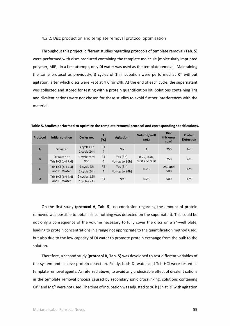
Mariana Isabel Fonseca Neves 59
4.2.2. Disc production and template removal protocol optimization
Throughout this project, different studies regarding protocols of template removal (Tab. 5)
were performed with discs produced containing the template molecule (molecularly imprinted
polymer, MIP). In a first attempt, only DI water was used as the template removal. Maintaining
the same protocol as previously, 3 cycles of 1h incubation were performed at RT without
agitation, after which discs were kept at 4ºC for 24h. At the end of each cycle, the supernatant
was collected and stored for testing with a protein quantification kit. Solutions containing Tris
and divalent cations were not chosen for these studies to avoid further interferences with the
material.
Table 5. Studies performed to optimize the template removal protocol and corresponding specifications.
Protocol Initial solution Cycles no. T
(ºC) Agitation
Volume/well
(mL)
Disc thickness
(µm)
Protein Detection
A DI water 3 cycles 1h
1 cycle 24h
RT
4 No 1 750 No
B DI water or
Tris HCl (pH 7.4)
1 cycle total 96h
RT
4
Yes (3h)
No (up to 96h)
0.25, 0.40, 0.60 and 0.80
750 Yes
C Tris HCl (pH 7.4)
and DI Water
1 cycle 3h
1 cycle 24h
RT
4
Yes (3h)
No (up to 24h) 0.25
250 and 500
Yes
D Tris HCl (pH 7.4)
and DI Water
2 cycles 1.5h
2 cycles 24h RT Yes 0.25 500 Yes
On the first study (protocol A, Tab. 5), no conclusion regarding the amount of protein
removed was possible to obtain since nothing was detected on the supernatant. This could be
not only a consequence of the volume necessary to fully cover the discs on a 24-well plate,
leading to protein concentrations in a range not appropriate to the quantification method used,
but also due to the low capacity of DI water to promote protein exchange from the bulk to the
solution.
Therefore, a second study (protocol B, Tab. 5) was developed to test different variables of
the system and achieve protein detection. Firstly, both DI water and Tris HCl were tested as
template removal agents. As referred above, to avoid any undesirable effect of divalent cations
in the template removal process caused by secondary ionic crosslinking, solutions containing
Ca2+ and Mg2+ were not used. The time of incubation was adjusted to 96 h (3h at RT with agitation

60 Mariana Isabel Fonseca Neves
and the rest with no agitation at 4 ºC). This was done to ensure the solution had reached its
equilibrium of protein saturation when analyzed. At the end of 3h incubation, 20µL of
supernatant were sampled and stored for further analysis and comparison with samples from
96h. Also, the volume of incubation solution was changed from 1 mL/well for 0.25, 0.4, 0.6 or
0.8 mL/well by using a 48-well plate which ensured the full covering of discs by the template
removal solution. Applying these adjustments enabled protein quantification and results are
presented on Fig. 17.
The results obtained show that ALMA 7 MIP discs allow higher levels of template removal
than ALMA 5 discs and that this difference is more prominent when incubation is performed
solely in DI water. The difference observed between both materials was expected since the
lower swelling observed for ALMA 5 in the previously performed studies lead to higher protein
entrapment within the bulk of the material. On the other hand, the greater capacity of ALMA 7
discs to swell, thus relaxing and expanding the polymer mesh, enabled higher protein diffusion.
Incubation in DI water
0
20
40
60
80
100
0.25 0.4 0.6 0.8
Volume (mL)
Rem
oved
BS
A (
%)
Incubation in Tris HCl
0.250
20
40
60
80
100
0.4 0.6 0.8
Volume (mL)
ALMA 5, 3h
ALMA 5, 96h
ALMA 7, 3h
ALMA 7, 96h
Figure 17. Effect of solution, volume and time of incubation in the amount of removed BSA from ALMA 5 and ALMA 7 alginate discs. Results obtained for n=1 disc per condition.
The best results for BSA removal were achieved in Tris HCl solution, being around 50 % and
70 % for ALMA 5 and ALMA 7 at 96 h, respectively, against 30 % and 61 % in DI water for the
same samples. The higher protein removal observed in Tris HCl incubated discs is most likely
caused by pH. While DI water has a pH value of around 5.5-5.6, Tris HCl solution was adjusted

Mariana Isabel Fonseca Neves 61
to pH 7.4. This increase in pH value may stimulate protein removal as more BSA molecules
become negatively charged and thus are repulsed from the negatively charged net of alginate
[70, 79, 80].
Regarding the incubation solution volume, no conclusions can be made regarding its effect
on amount of protein removed because saturation events occurred. In fact, at the end of 3h
some of the solutions had the same or near amount of protein than at 96h, either caused by
saturation of the solution or by incapacity to remove more protein from the disc. Nevertheless,
these results were important for two main aspects: first, to understand the range of volumes
that could be used that would still allow protein detection as fast as 3h after starting incubation;
and secondly to determine how fast saturation could occur in order to further adjust incubation
cycles in terms of number and duration.
Minding these results Tris HCl (pH 7.4) was selected as initial incubation solution to proceed
to further tests, along with a 0.25mL solution which would allow obtaining more concentrated
samples, thus enabling an easier detection of protein amounts and protein variations.
Template removal
3 240
20
40
60
80
100ALMA 5, 250m
ALMA 5, 500m
ALMA 7, 250m
ALMA 7, 500m
Time (h)
Rem
oved
BS
A (
%)
Figure 18. Effect of thickness in the amount of protein removed. Results obtained for n=1 disc per condition.
To further improve protein diffusion within discs and increase the area of available surface,
a third study (protocol C, Tab. 5) was performed where disc thickness was reduced to either 250
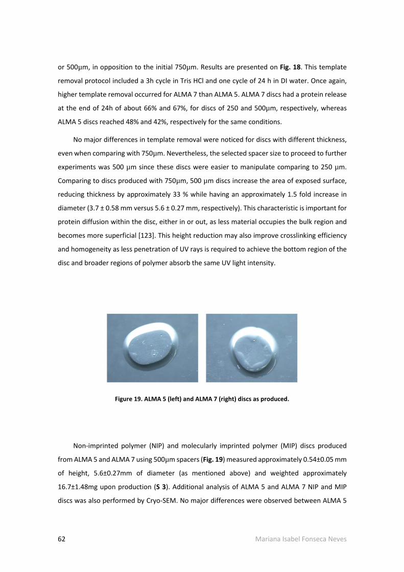
62 Mariana Isabel Fonseca Neves
or 500µm, in opposition to the initial 750µm. Results are presented on Fig. 18. This template
removal protocol included a 3h cycle in Tris HCl and one cycle of 24 h in DI water. Once again,
higher template removal occurred for ALMA 7 than ALMA 5. ALMA 7 discs had a protein release
at the end of 24h of about 66% and 67%, for discs of 250 and 500µm, respectively, whereas
ALMA 5 discs reached 48% and 42%, respectively for the same conditions.
No major differences in template removal were noticed for discs with different thickness,
even when comparing with 750µm. Nevertheless, the selected spacer size to proceed to further
experiments was 500 µm since these discs were easier to manipulate comparing to 250 µm.
Comparing to discs produced with 750µm, 500 µm discs increase the area of exposed surface,
reducing thickness by approximately 33 % while having an approximately 1.5 fold increase in
diameter (3.7 ± 0.58 mm versus 5.6 ± 0.27 mm, respectively). This characteristic is important for
protein diffusion within the disc, either in or out, as less material occupies the bulk region and
becomes more superficial [123]. This height reduction may also improve crosslinking efficiency
and homogeneity as less penetration of UV rays is required to achieve the bottom region of the
disc and broader regions of polymer absorb the same UV light intensity.
Figure 19. ALMA 5 (left) and ALMA 7 (right) discs as produced.
Non-imprinted polymer (NIP) and molecularly imprinted polymer (MIP) discs produced
from ALMA 5 and ALMA 7 using 500µm spacers (Fig. 19) measured approximately 0.54±0.05 mm
of height, 5.6±0.27mm of diameter (as mentioned above) and weighted approximately
16.7±1.48mg upon production (S 3). Additional analysis of ALMA 5 and ALMA 7 NIP and MIP
discs was also performed by Cryo-SEM. No major differences were observed between ALMA 5

Mariana Isabel Fonseca Neves 63
and ALMA 7 alginate discs nor between NIP and MIP discs. Fig. 20 shows representative images
obtained by Cryo-SEM. It was possible to observe the existence of macro-pores (Fig.20A) that
were sometimes concomitant with the presence of a dense net of micro-pores (Fig.20B). For
some preparations, a transition zone was also observed (Fig.20C). No major conclusions can be
formulated regarding these data since the required Cryo-SEM processing of samples for the
assay (freezing, fracturing, sublimation and coating).
Figure 20. Representative Cryo-SEM images of ALMA 5 and ALMA 7 discs.For all four materials (ALMA 5 and 7, NIP and MIP discs), it was possible to observe the existence of either macro-pores (A), macro-pores with dense nets of micro-pores (B) and also transition zones (C). Scale bars represent 60µm.
Considering all data collected up until this point, a final template removal protocol
(protocol D, Tab. 5) was defined: two cycles of 1h 30min each in Tris HCl (pH 7.4), instead of one
cycle of 3h, to avoid protein saturation in the solution and promote higher protein diffusion at
a stage where swelling events are pronounced; followed by 2 cycles of 24h incubation in DI
water, instead of only 1 cycle of 24h, to further remove any remaining protein and Tris residues.
Additionally, the whole protocol was performed in continuous agitation (150rpm, RT) to
promote the diffusion of protein and solution throughout the discs.
This template removal protocol was further evaluated by different methodologies and
results are presented and discussed in the following section.

64 Mariana Isabel Fonseca Neves
4.3. Template removal analysis and characterization
4.3.1. Template removal quantification by analysis of supernatant
Fig. 21 and Tab. 6 present results from template removal for ALMA 5 and ALMA 7 MIP discs
by protein quantification in the incubation solution (supernatant), being therefore an indirect
method of quantification.
As it can be observed on Fig. 21 and Tab. 6, both ALMA 5 and ALMA 7 discs presented a
significant protein removal in the first 1.5h of incubation, with more than 50% of protein
removed during this period of time for both materials. At 3h of incubation, these values
increased to 61.4% and 83.5%, with significant differences starting to be noticed between ALMA
5 and ALMA 7 discs. The same tendency was observed on the following 24 and 48h as these
values increase to a maximum of 65.8% (24 h) for ALMA 5 and 94.2% (48 h) for ALMA 7.
00
50
100
150
200
250
243 481.5
***
*****
Time (h)
Cu
mu
lati
ve a
mo
un
t o
f B
SA
(
g)
1.5 3 24 480
40
80
120
100 *** **
Time (h)
%
ALMA 5 ALMA 7
Template Removal
ALMA 5 ALMA 7
Amount of BSA in supernatant
A B
Figure 21. Amount of BSA removed in ALMA 5 and ALMA 7 discs (A) and percentage of template removal (B) by protein quantification in the supernatant (incubation solution). Points and bars represent mean values of n=4 discs ± SD; horizontal and vertical asterisks represent statistical differences (* p < 0.05, ** p < 0.01, *** p < 0.001) between different timepoints and different materials, respectively.

Mariana Isabel Fonseca Neves 65
Table 6. Amount of BSA removed in ALMA 5 and ALMA 7 discs and percentage of template removal determined by protein quantification in supernatant (incubation solution). Data represent mean values of n=4 discs ± SD. Data corresponds to data shown in Fig. 21.
Between 24h and 48h, the amount of protein removed from discs is barely altered. This
may be indeed because the rest of protein remaining inside discs is deeply entrapped within the
bulk, due to lower diffusional forces which are not enough to promote protein exit from the disc,
or because the amount of protein present in the solution in comparison with its volume starts
reaching the limit of the detection range of the protein assay kit used to perform these
quantifications.
4.3.2. Template removal quantification by analysis of digested discs
Another approach used for quantifying the amount of protein being removed from the disc
was by quantification of protein present in digested discs (direct method). Since this approach
is destructive, only timepoints of 0, 3 and 48h were tested. Results are presented in Fig. 22 and
Tab. 7. Results obtained by this method were in concordance with previously shown data by
supernatant analysis and tend to present lower standard deviations than the previous method.
It was possible to verify a significant amount of protein release occurring in the first 3h of
incubation, at the end of which 56.7% and 89.9% of protein was removed from ALMA 5 and
ALMA 7 MIP discs, respectively. At the end of the template removal protocol this values reached
69.8% and 98.5%, respectively, representing an additional 10% increase, approximately. Again,
significant differences between ALMA 5 and ALMA 7 alginate were observed starting at 3h and
Time (h) 1.5 3 24 48
ALMA 5
Cumulative mBSA in supernatant (µg)
107.2±6.82 122.9±11.39 131.6±14.00 128.1±14.84
Removed template (%) 53.61±3.41 61.4±5.69 65.8±7.00 64.0±7.42
ALMA 7
Cumulative mBSA in supernatant (µg)
118.7±8.74 166.9±16.63 186.9±14.33 188.3±14.88
Removed template (%) 59.3±4.37 83.5±8.32 93.5±7.17 94.2±7.44

66 Mariana Isabel Fonseca Neves
these differences were even more pronounced once the template removal protocol was
completed.
00
50
100
150
200
250
243 48
**
*****
***
Time (h)
Am
ou
nt
of
BS
A in
dis
c (
g)
3 480
20
40
60
80
100**
***
Time (h)
%
Template RemovalAmount of BSA in discs
ALMA 5 ALMA 7ALMA 5 ALMA 7
A B
Figure 22 Amount of BSA removed in ALMA 5 and ALMA 7 discs (A) and percentage of template removal (B) by protein quantification in digested discs. Points and bars represent mean values of n=4 discs ± SD; horizontal and vertical asterisks represent statistical differences (** p < 0.01, *** p < 0.001) between different timepoints and different materials, respectively.
Table 7. Amount of BSA removed in ALMA 5 and ALMA 7 discs and percentage of template removal
determined by protein quantification in digested discs.Points and bars represent mean values of n=4
discs ± SD. Values corresponding to Fig. 22.
Time (h) 0 3 48
ALMA 5
mBSA in disc (µg) 198.8±14.23 85.9±9.84 59.9±3.09
Removed template (%)
- 56.7±4.81 69.8±1.84
ALMA 7
mBSA in disc (µg) 194.6±7.35 19.8±3.11 2.9±1.53
Removed template (%)
- 89.9±1.52 98.5±0.84

Mariana Isabel Fonseca Neves 67
Overall, these data indicated that the first 3h of incubation were crucial for template
removal, with more than half of the protein being removed at this stage. This was concomitant
with the significant increase of swelling ratio occurring at this phase, caused by rapid entrance
of solution into the discs (Fig. 23). This event not only helped protein removal by promoting
polymer expansion, leading to more free space in the polymer mesh, allowing better protein
mobility within the disc, but also by creating diffusional forces to support BSA exit out of the disc
and into the solution.
0 240
4
8
12ALMA 5 NIP
ALMA 5 MIP
ALMA 7 NIP
ALMA 7 MIP
48
**
**
Time (h)
Sw
ellin
g (
wt/w
t0)
*
Figure 23. Swelling profile of ALMA 5 and ALMA 7 NIP and MIP discs during template removal protocol. Maximum swelling ratio of approximately 7 for ALMA 5 and 9 for ALMA 7 discs at 48h.Data represent mean values of n=4 discs ± SD. Statistical analysis performed in comparison with t=0 h by unpaired t test with Welch’s correction. Asterisks represent statistical differences between timepoints, * < 0.05, ** p < 0.01.
Nevertheless, it was in the following 48h that major differences occurred between both
materials. For ALMA 5 MIP discs, despite the amount of protein still present in the disc
(approximately 40% at 3h) and the continuous increase in swelling ratio, template removal did
not seem to follow the same tendency. This was namely true when analyzing results from
quantifications in the supernatant, since by quantification of digested discs it was possible to

68 Mariana Isabel Fonseca Neves
still detect more 13% of removed protein between 3 and 48h of protocol. Being an indirect
method of quantification, determination of template removal by analysis of supernatant was
more prone to fail detection of variations in protein content, and this was particularly true on
the final washing steps. The small amount of protein being removed to the solution causes low
protein variations that were most likely out of the detection range of the kit used during this last
phase of template removal.
Differences between ALMA 5 and ALMA 7 discs may be caused by the different protonation
state of these materials, already explained above, which also influences the swelling behavior.
Even though no significant differences were obtained for ALMA 5 and ALMA 7 swelling ratios at
48 h (7 and 9, respectively, Fig. 23), a closer look at these values shows that they represent a
difference of 200 % in swelling ratio. By other words, for the same condition and same timepoint,
ALMA 7 discs suffered an additional doubling on weight (regarding its initial value) while
comparing to the ALMA 5 discs. When working at a µg quantification range such differences
become quite significant.
Results obtained by both detection methods were highly comparable, pointing to a total of
protein removal of approximate 70% for ALMA 5 and over 94% for ALMA 7 at the end of the
template removal process. The fact that no more protein was removed from ALMA 5 discs may
be caused by a combination of lower diffusional forces and entrapment of the remaining protein
deeply within the mesh of the alginate disc - thus being impossible to remove despite the
number and duration of template removal cycles – and the lower swelling ratio. In the study
reported by Bayer and colleagues [79], who developed a molecularly imprinted ionically-
crosslinked alginate film system, only around 67% of the template was removed during the
washing steps at the end of approximately 160h, indicating that the results obtained with the
present template removal protocol are promising. These differences may be caused by different
swelling ratios since in Bayer et al. [79] this parameter reached a maximum of approximately
only 2.5 at the end of the sixth day. This is, of course, highly dependent on the type of alginate
and the type of crosslinking used. Template removal protocols vary in the literature of alginate
MIP systems and strongly depend on the type of MIP produced. Duration of these protocols also
varies widely, from several hours to several days [44, 49, 72, 80, 81]. Herrerto et al. [80]
optimized a template removal protocol for BSA-MIP alginate microcapsules (ionic crosslinking)
using Tris HCl with 1% CaCl2 (pH 7.4) and achieved almost 90 % of template removal at the end
of 5 h [80]. In this project, at the end of 3h almost 60% for ALMA 5 and 90% for ALMA 7 of

Mariana Isabel Fonseca Neves 69
template removal was already achieved. Comparing results obtained by Herrero et al. [80], this
results are quite promising, especially because they refer to a nearly bulk system where
template removal is harder to achieve.
4.3.2. Template removal quantification by GTA method
Throughout this project, in order to overcome obstacles regarding protein detection, an
alternative GTA-based method was developed based on work presented by Ma et al. [104]. In
their work, Ma and coworkers [104] created a green fluorescence protein hydrogel composed
of BSA crosslinked with GTA, which was able to exhibit green and red fluorescence when excited
at λ =470nm and 595nm, respectively [124]. Despite having an intrinsic fluorescence derived
from two tryptophan residues (excitation at λ=279nm and emission at λ=348nm), this BSA
profile is affected by reaction with GTA. In 1968, Habeeb et al. [125] studied the reactivity of
functional groups of amino acid residues present in proteins with GTA. The authors described
the reaction between GTA and proteins like BSA or ovalbumin as occurring predominantly with
the ϵ-amino groups of lysine to form mainly intermolecular crosslinkages [125]. These
interactions can explain the formation of new classes of compounds formed by BSA-GTA
crosslinkage which are able to absorb and emit at different ranges of wavelengths.
As so, in preliminary studies, ALMA 5 NIP and MIP discs were incubated in GTA solution for
30mins at RT and observed in a wide-field microscope at different timepoints of processing: as
produced (t=0h) and throughout template removal protocol (t=3, 24 and 48h) (Fig. 24). It is
possible to see clear differences between t=0h NIP (Fig. 24A) and MIP discs (Fig. 24B). While MIP
discs still containing protein presented high fluorescence for all channels in the disc region, the
same was not observed for NIP discs which do not contain protein in their solution.
Throughout the template removal protocol, MIP discs presented continuously lower
fluorescence, indicating progressively lower protein contents. Once again, a great difference was

70 Mariana Isabel Fonseca Neves
Figure 24. Images obtained by Zoe Fluorescent Cell imager for ALMA 5 NIP (A) and MIP (B) discs at different timepoints of production. Images of brightfield and green (G), red (R) and blue (B) channels can be observed, respectively.

Mariana Isabel Fonseca Neves 71
observed between t=0h and t=3h, while from this timepoint on variations became narrower
despite being perceptible.
It should be mentioned that for the three channels (G, R and B), in all discs, borders could
be observed as a green, red or blue lines, respectively. This was not caused by any major
fluorescence event occurring in the sample itself, but most likely due to light reflection occurring
in the thick border of discs or coming from reflections on the walls of each well (samples were
incubated in 24-well plates), due to the wide region of incidence of the LED lights and non-
existent removal of out-of-focus light. Additionally, this border light varied in thickness due to
low focus capacity caused by the thickness of the discs.
Overall, this method presented consistency between samples and returned expected
results regarding the variations of protein content during the whole processing and the observed
variations in fluorescence. Using a qualitative analysis, it could be concluded that the
information obtained by this method was in agreement with data from the previously studied
techniques.
Figure 25. Representative images of standard samples obtained by inverted confocal microscopy. Images are the result of a z-projection (4 stacks per image) containing 1% (A), 0.5% (B), 0.25% (C) and 0% BSA (D) after incubation overnight in 25% glutaraldehyde solution (4ºC). Section (E) is the result of contrast adjustment of section D. 0% and 1% BSA discs correspond to the same composition as NIP and MIP discs, respectively. Scale bar represents 200µm, λex= 488nm.

72 Mariana Isabel Fonseca Neves
In order to provide quantitative analysis of the template removal protocol using this
method, it was necessary to develop a strategy for protein quantification by correlation with
BSA autofluorescence. To do so, inverted confocal microscopy was used to improve lateral and
axial resolution (comparing to the previously used wide-field fluorescence microscopy), by
eliminating out-of-focus light, an inherent characteristic of inverted confocal microscopy [126].
As a proof of concept, in an attempt to demonstrate that it was possible to correlate
autofluorescence with protein content, a methodology was developed in which standard
samples of ALMA 5 discs containing from 0 up to 1% BSA in their composition were analyzed
under the microscope after incubation with GTA and at a λex = 488nm. Images obtained are
shown in Fig. 25. As expected, a decrease in green fluorescence was observed, which was
concomitant with a decrease in protein content with 1% BSA discs (Fig. 25A) presenting higher
green fluorescence. For 0 % BSA discs (Fig. 25D) it was not possible to observe any fluorescence
unless contrast and brightness are adjusted (Fig. 25E).
BSAMean Calibration Curve
0 2 4 6 8 100
1000
2000
3000
4000
y = 284.06x + 158.36
R2 = 0.983
[BSA] mg/mL
Mean
gra
y v
alu
e
(A.U
.)
Figure 26. Calibration curve obtained by analysis of inverted confocal microscopy images to correlate the Mean Gray Value (A.U.) with the amount of BSA (mg/mL) present in discs. Results obtained from 3 measurements per disc, n=3 discs.

Mariana Isabel Fonseca Neves 73
In order to check if the observed correlation between green fluorescence and protein
concentration followed a linear correlation, the Mean gray value, or solely Mean (arbitrary units,
A.U.) was used as a measure for quantifying fluorescence.
Following this approach, it was indeed possible to linearly correlate green fluorescence
with the amount of protein present in discs (Fig. 26).
Figure 27. Representative images of samples before (A and C) and after (B and D) template removal protocol obtained by inverted confocal microscopy. Images are the result a z-projection (4 stacks per image) of t=0h and t=48h samples after incubation overnight in 25% GTA solution (4ºC). Scale bar represents 200µm, λex= 488nm.
Even though using the Mean as measure of fluorescence was the selected approach, also
Integrated Density (IntDen, A.U.) could have been used. However, since IntDen is obtained by

74 Mariana Isabel Fonseca Neves
multiplying the Mean by the area of measurement and, in the case of this project, all
measurements performed had exactly the same dimensions (area = 39921.913, S 4), results
would be proportional. Examples of measurements performed and a calibration curve obtained
by correlation of IntDen and protein concentration are shown in Supplementary Data (S 4 and S
5).
Afterwards, ALMA 5 samples which undergone template removal protocol were analyzed
following the same protocol and results are shown in Fig. 27 and Fig. 28.
Differences in fluorescence were visible between ALMA 5 MIP discs as produced (Fig. 27A)
and after template removal (Fig. 27B) and these differences correlated with significant
differences in Mean values and amount of protein detected in discs (Fig. 28A-B). Oppositely, no
major differences in NIP discs could be observed (Fig. 27C-D and Fig. 28A).
0 h 48 h0
50
100
150
200
0
20
40
60
80
100***
mB
SA
(ug
)
%
0h 48h0
200
400
6002000
2500
3000***
*
****
NIP
MIP
Mean
gra
y v
alu
e
(A.U
.)
A B
NIP MIP mBSA in disc Template removal
Figure 28. Representation of mean gray value of NIP and MIP discs (A) and amount of protein present in MIP discs and corresponding template removal (B) before (0h) and after template removal protocol (48h) determined by GTA method. Mean gray values represent absolute values measured. Bars represent mean values ± SD, n=3 discs (3 measurements per disc). Statistical analysis performed by unpaired t test with Welch’s correction, * p < 0.05, *** p < 0.001.
Even though qualitative results were as expected, quantitative analysis of data showed a
template removal of around 95%, much higher than the approximately 70% obtained for ALMA
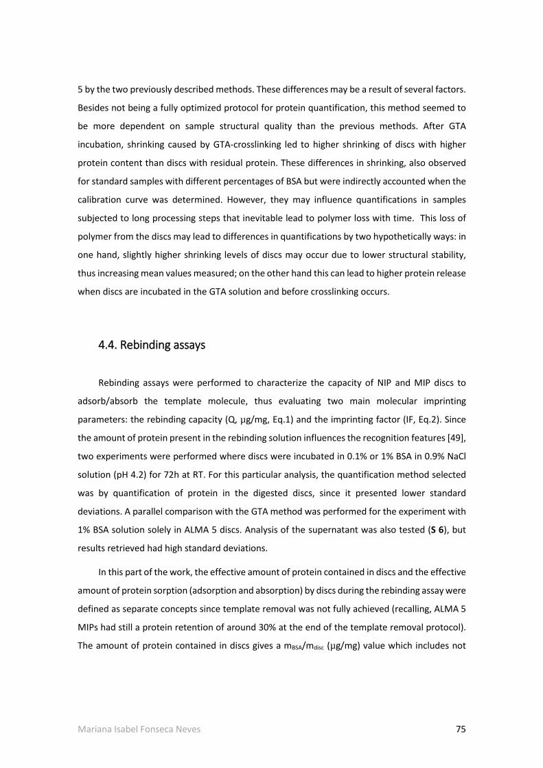
Mariana Isabel Fonseca Neves 75
5 by the two previously described methods. These differences may be a result of several factors.
Besides not being a fully optimized protocol for protein quantification, this method seemed to
be more dependent on sample structural quality than the previous methods. After GTA
incubation, shrinking caused by GTA-crosslinking led to higher shrinking of discs with higher
protein content than discs with residual protein. These differences in shrinking, also observed
for standard samples with different percentages of BSA but were indirectly accounted when the
calibration curve was determined. However, they may influence quantifications in samples
subjected to long processing steps that inevitable lead to polymer loss with time. This loss of
polymer from the discs may lead to differences in quantifications by two hypothetically ways: in
one hand, slightly higher shrinking levels of discs may occur due to lower structural stability,
thus increasing mean values measured; on the other hand this can lead to higher protein release
when discs are incubated in the GTA solution and before crosslinking occurs.
4.4. Rebinding assays
Rebinding assays were performed to characterize the capacity of NIP and MIP discs to
adsorb/absorb the template molecule, thus evaluating two main molecular imprinting
parameters: the rebinding capacity (Q, µg/mg, Eq.1) and the imprinting factor (IF, Eq.2). Since
the amount of protein present in the rebinding solution influences the recognition features [49],
two experiments were performed where discs were incubated in 0.1% or 1% BSA in 0.9% NaCl
solution (pH 4.2) for 72h at RT. For this particular analysis, the quantification method selected
was by quantification of protein in the digested discs, since it presented lower standard
deviations. A parallel comparison with the GTA method was performed for the experiment with
1% BSA solution solely in ALMA 5 discs. Analysis of the supernatant was also tested (S 6), but
results retrieved had high standard deviations.
In this part of the work, the effective amount of protein contained in discs and the effective
amount of protein sorption (adsorption and absorption) by discs during the rebinding assay were
defined as separate concepts since template removal was not fully achieved (recalling, ALMA 5
MIPs had still a protein retention of around 30% at the end of the template removal protocol).
The amount of protein contained in discs gives a mBSA/mdisc (µg/mg) value which includes not

76 Mariana Isabel Fonseca Neves
only the amount of protein adsorbed/absorbed but also protein remaining after template
removal (only in the case of MIP discs).
Oppositely, the amount of protein adsorbed/absorbed during the rebinding assay was
determined by excluding the influence of any protein remaining inside the discs after template
removal. This second concept corresponds, therefore, to the rebinding capacity. Based on these
values, an IF value was also determined. For NIP discs, both concepts (amount of protein
contained in discs and adsorbed/absorbed by discs) correspond to the same value as these discs
were never in contact with any protein content up until this stage.
0 1200
4
8
12ALMA 5 NIP
ALMA 5 MIP
ALMA 7 NIP
ALMA 7 MIP
48
Template removal Rebinding assay
**
* *
Total time (h)
Sw
ellin
g r
ati
o (
wt/w
t0)
Figure 29. Swelling profile of ALMA 5 and ALMA 7 NIP and MIP discs during template removal (3h and 48h) and rebinding protocol (72h of rebinding assay, total 120h). Maximum swelling ratio of approximately 7 for ALMA 5 and 9 for ALMA 7 discs at 48h. Data represent mean values of n=4 discs ± SD. Statistical analysis performed in comparison with t=0h by unpaired t test with Welch’s correction. Asterisks represent statistical differences between different timepoints, * < 0.05, ** p < 0.01.
Before proceeding to protein quantifications, it was possible to observe a clear alteration
on swelling profile of ALMA discs. Contrarily to the high increase in swelling ratio occurring
during the template removal process, during the rebinding assay both ALMA 5 and ALMA 7 discs
suffered a shrinking process (Fig. 29). This deswelling event was so pronounced that led to

Mariana Isabel Fonseca Neves 77
swelling ratios near or below the ones observed at t=3h of template removal (2.6 and 3.9 for
ALMA 5 and 7 discs, respectively). In fact, this could be an explanation why protein quantification
by analysis of the supernatant was affected during this assay: as water content in discs was
released to the incubation solution, variations in incubation volume led to higher measuring
errors.
This deswelling event was most likely caused by a combination of lower pH values (4.2
against 5.5 from DI water) and salt presence (0.9% NaCl) in the rebinding solution. On one hand,
lowering the pH means a higher presence of H+ in the solution, which strongly interact with the
negatively charged alginate, namely the carboxylate (COO-) groups. As pH decreases alginate
COO- groups become carboxylic acid groups (COOH) with neutral electric charge, leading to a
reduction on electrostatic repulsions and consequent contraction of the polymeric chains,
lowering water absorbency [116] and decreasing hydrogel swelling.
On the other hand, decrease in swelling capacity of anionic gels is frequently affected by
salts present in solution due to a “charge screening effect” [117]. This effect leads to
electrostatic repulsion between anions and is caused by the presence of additional cations. The
charge screening effect has been described for alginate and other anionic hydrogels [116, 117]
and is strictly dependent on the type of salt and concentration in solution. For instance, in the
case of divalent ions, an additional decrease in swelling due to ionic crosslinking events must be
accounted [116]. Additionally, this effect can even depend on cation radius, as previously
reported by other authors [116], since it affects electrostatic interactions with anionic groups,
including carboxylate [127].
pH and salts can affect both the molecular imprinting process and consequent recognition
features of produced MIPs [75]. As a consequence, for this part of the project rebinding studies
were carried out maintaining the same pH (4.2) and salts (0.9% NaCl) as in the initial BSA
solution. In fact, Zhao et al. [75] reported maximum Q and IF values at pH values of
approximately 4.2 in calcium phosphate/polyacrylate/alginate hybrid polymer BSA-MIP
microspheres [75].
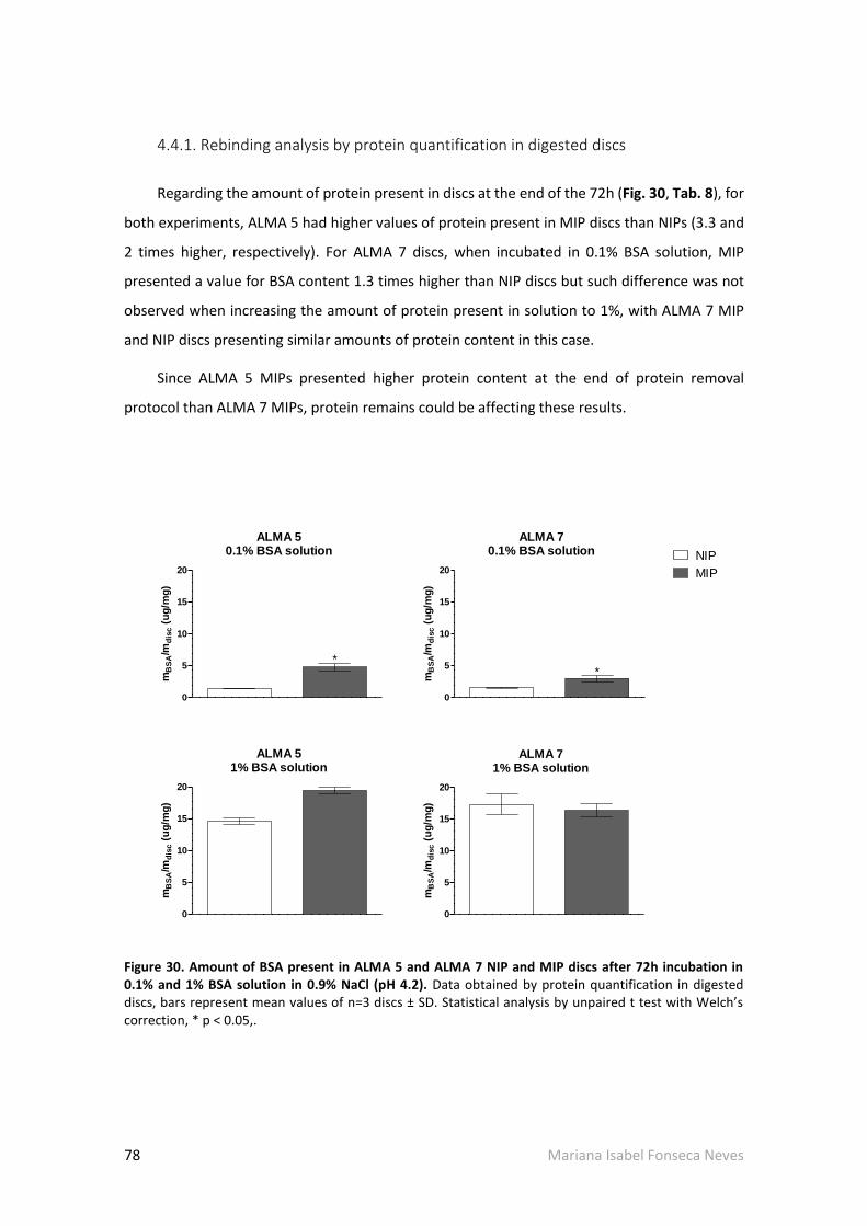
78 Mariana Isabel Fonseca Neves
4.4.1. Rebinding analysis by protein quantification in digested discs
Regarding the amount of protein present in discs at the end of the 72h (Fig. 30, Tab. 8), for
both experiments, ALMA 5 had higher values of protein present in MIP discs than NIPs (3.3 and
2 times higher, respectively). For ALMA 7 discs, when incubated in 0.1% BSA solution, MIP
presented a value for BSA content 1.3 times higher than NIP discs but such difference was not
observed when increasing the amount of protein present in solution to 1%, with ALMA 7 MIP
and NIP discs presenting similar amounts of protein content in this case.
Since ALMA 5 MIPs presented higher protein content at the end of protein removal
protocol than ALMA 7 MIPs, protein remains could be affecting these results.
ALMA 50.1% BSA solution
0
5
10
15
20
*
mB
SA
/md
isc (
ug
/mg
)
ALMA 70.1% BSA solution
0
5
10
15
20
*
mB
SA
/md
isc (
ug
/mg
)
ALMA 51% BSA solution
0
5
10
15
20
mB
SA
/md
isc (
ug
/mg
)
ALMA 71% BSA solution
0
5
10
15
20
mB
SA/m
dis
c (
ug
/mg
)
NIP
MIP
Figure 30. Amount of BSA present in ALMA 5 and ALMA 7 NIP and MIP discs after 72h incubation in 0.1% and 1% BSA solution in 0.9% NaCl (pH 4.2). Data obtained by protein quantification in digested discs, bars represent mean values of n=3 discs ± SD. Statistical analysis by unpaired t test with Welch’s correction, * p < 0.05,.
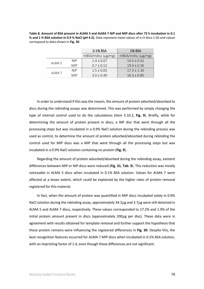
Mariana Isabel Fonseca Neves 79
Table 8. Amount of BSA present in ALMA 5 and ALMA 7 NIP and MIP discs after 72 h incubation in 0.1 % and 1 % BSA solution in 0.9 % NaCl (pH 4.2). Data represent mean values of n=3 discs ± SD and values correspond to data shown in Fig. 30.
In order to understand if this was the reason, the amount of protein adsorbed/absorbed to
discs during the rebinding assays was determined. This was performed by simply changing the
type of internal control used to do the calculations (item 3.10.2, Fig. 9). Briefly, while for
determining the amount of protein present in discs, a NIP disc that went through all the
processing steps but was incubated in a 0.9% NaCl solution during the rebinding process was
used as control, to determine the amount of protein adsorbed/absorbed during rebinding the
control used for MIP discs was a MIP that went through all the processing steps but was
incubated in a 0.9% NaCl solution containing no protein (Fig. 9).
Regarding the amount of protein adsorbed/absorbed during the rebinding assay, existent
differences between MIP or NIP discs were reduced (Fig. 31, Tab. 9). This reduction was mostly
noticeable in ALMA 5 discs when incubated in 0.1% BSA solution. Values for ALMA 7 were
affected at a lesser extent, which could be explained by the higher rates of protein removal
registered for this material.
In fact, when the amount of protein was quantified in MIP discs incubated solely in 0.9%
NaCl solution during the rebinding assay, approximately 34.2µg and 3.7µg were still detected in
ALMA 5 and ALMA 7 discs, respectively. These values corresponded to 17.2% and 1.9% of the
initial protein amount present in discs (approximately 200µg per disc). These data were in
agreement with results obtained for template removal and further support the hypothesis that
these protein remains were influencing the registered differences in Fig. 30. Despite this, the
best recognition features occurred for ALMA 7 MIP discs when incubated in 0.1% BSA solution,
with an imprinting factor of 1.4, even though these differences are not significant.
0.1% BSA 1% BSA
mBSA/mdisc (µg/mg) mBSA/mdisc (µg/mg)
ALMA 5
NIP 1.4 ± 0.07 14.6 ± 0.42
MIP 4.7 ± 0.52 19.4 ± 0.36
ALMA 7
NIP 1.5 ± 0.05 17.3 ± 1.30
MIP 3.0 ± 0.40 16.3 ± 0.85

80 Mariana Isabel Fonseca Neves
Figure 31. Rebinding capacity (amount of BSA adsorbed/absorbed during rebinding assay) of ALMA 5 and ALMA 7 NIP and MIP discs after 72h incubation in 0.1% and 1% BSA solution in 0.9% NaCl (pH 4.2). Data represent mean values of n=3 discs ± SD. Statistical analysis by unpaired t test with Welch’s correction (p < 0.05).
Table 9. Rebinding capacity (amount of BSA adsorbed/absorbed during rebinding assay) of ALMA 5 and ALMA 7 NIP and MIP discs after 72h incubation in 0.1% and 1% BSA solution in 0.9% NaCl (pH 4.2). Data represent mean values of n=3 discs ± SD and values correspond to data shown in Fig. 31.
0.1% BSA 1% BSA
Q (µg/mg) IF Q (µg/mg) IF
ALMA 5 NIP 1.4 ± 0.07
0.9 ± 0.28 14.6 ± 0.42
1.1 ± 0.03
MIP 1.3 ± 0.36 16.6 ± 0.07
ALMA 7 NIP 1.5 ± 0.05
1.4 ± 0.30 17.3 ± 1.30
0.9 ± 0.10
MIP 2.1 ± 0.48 15.7 ± 0.83
The decrease in IF observed concomitantly to the increase of protein concentration in
incubation solution was expected and most likely caused by increased diffusional forces due to
ALMA 50.1% BSA solution
0
5
10
15
20
Q (
ug
/mg
)
ALMA 70.1% BSA solution
0
5
10
15
20
Q (
ug
/mg
)
ALMA 51% BSA solution
0
5
10
15
20
Q (
ug
/mg
)
ALMA 71% BSA solution
0
5
10
15
20Q
(u
g/m
g)
NIP
MIP

Mariana Isabel Fonseca Neves 81
higher amount of protein present outside the disc, forcing its entrance and unspecific protein
absorption into both NIP and MIP discs, and also by the possible increase in the amount of
protein adsorbed unto the surface of the discs.
4.4.2. Rebinding analysis by GTA method
In order to further correlate the herein developed GTA method, a rebinding assay was
performed on ALMA 5 NIP and MIP discs by incubation in a 1% BSA solution. Standard samples
were again prepared for visualization under the confocal microscope on the same day ALMA 5
samples were visualized. A new calibration curve was determined and is presented on Fig. 32.
Comparing Fig. 32 with the previous calibration curve (Fig. 26), it was possible to verify
consistency between both equations and high coefficients of determination (R2 ~0.98) even
though these calibration curves were resultant of samples from different preparations. Once
again, a calibration curve was obtained by correlation with the correspondent IntDen values and
is presented in Supplementary Data (S 7).
Fig. 33 shows representative images of ALMA 5 NIP and MIP discs over the whole molecular
imprinting process (Fig.33A-D) and rebinding assay (Fig.33E-H). In a qualitative analysis, it was
possible to observe differences between NIP and MIP samples and between different
timepoints. MIP discs presented slightly higher green fluorescence than NIP discs when
incubated in 1% BSA solution (Fig.33E-F). Once again, this may have been caused by a cumulative
effect of protein still remaining in MIP discs after template removal protocol. This hypothesis is
supported by Fig.33G which represents a MIP disc after 72h in solution without BSA with still
considerable green fluorescence. On the other hand, NIP discs exposed to the same conditions
presented lower green fluorescence.
Green fluorescence was correlated with Mean values (Fig.34A), amount of protein present
in discs and amount of protein sorption during rebinding assay (Fig.34B). No significant
differences were found between NIP and MIP Mean values and the same tendency was verified
for the amount of protein present in and adsorbed/absorbed into discs.
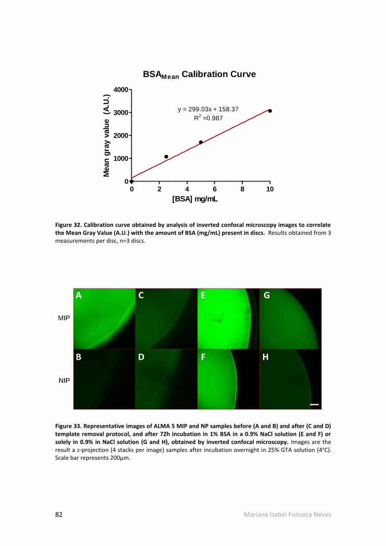
82 Mariana Isabel Fonseca Neves
BSAMean Calibration Curve
0 2 4 6 8 100
1000
2000
3000
4000
y = 299.03x + 158.37
R2
=0.987
[BSA] mg/mL
Mean
gra
y v
alu
e
(A.U
.)
Figure 32. Calibration curve obtained by analysis of inverted confocal microscopy images to correlate the Mean Gray Value (A.U.) with the amount of BSA (mg/mL) present in discs. Results obtained from 3 measurements per disc, n=3 discs.
Figure 33. Representative images of ALMA 5 MIP and NP samples before (A and B) and after (C and D) template removal protocol, and after 72h incubation in 1% BSA in a 0.9% NaCl solution (E and F) or solely in 0.9% in NaCl solution (G and H), obtained by inverted confocal microscopy. Images are the result a z-projection (4 stacks per image) samples after incubation overnight in 25% GTA solution (4ºC). Scale bar represents 200µm.

Mariana Isabel Fonseca Neves 83
Contrarily to what was expected, MIP discs incubated in 0.9% NaCl solution presented
higher Mean values and corresponding amount of protein (~781A.U. and 31µg) after these 72h
of incubation than after template removal (~413A.U. and 8µg). Such differences were not
noticed for NIP discs which presented approximated Mean values for both assays (~150 versus
~161, respectively).
The increase in Mean values for MIP control discs was not expected since no protein was
added after template removal to these internal controls and may have affected protein
quantification results. This event supports the hypothesis that, as it is currently designed, this
method is highly dependent on the structural quality of samples due to the shrinking effect
caused by glutaraldehyde crosslinking.
0
100
200
300
NIP MIP
mB
SA
( g
)
0
1000
2000
3000
4000
5000
NIP MIP
***
***
Mean
gra
y v
alu
e
(A.U
.)
A B
mBSA in disc1 % BSA 0.9 % NaCl mBSA adsorbed
Figure 34. Representation of Mean gray value of NIP and MIP discs during rebinding assay (A) and amount of protein present in and adsorbed/absorbed into NIPs and MIPs (B) after incubation in 1% BSA solution or 0.9% NaCl (internal controls) for 72h determined by GTA method. Mean gray values represent absolute values measured. Bars represent mean values ± SD, n= 3 discs (3 measurements per disc). Statistical analysis by unpaired t test with Welch’s correction, * p < 0.05, ** p < 0.01).
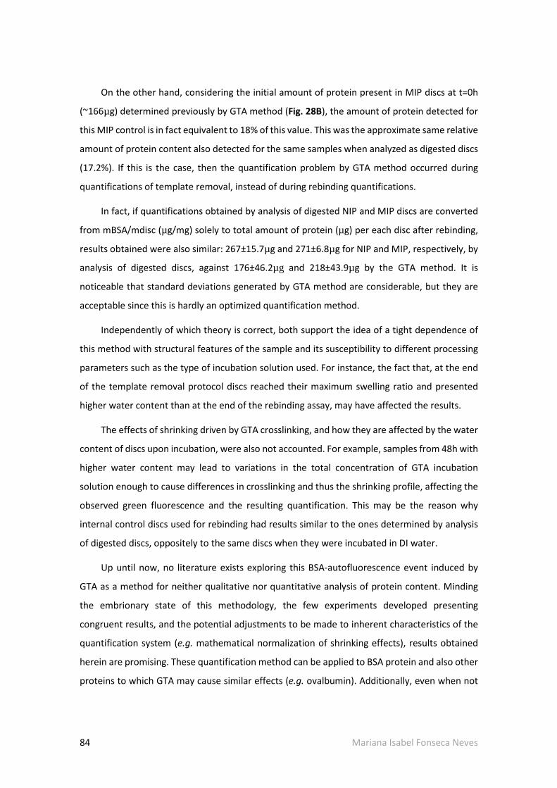
84 Mariana Isabel Fonseca Neves
On the other hand, considering the initial amount of protein present in MIP discs at t=0h
(~166µg) determined previously by GTA method (Fig. 28B), the amount of protein detected for
this MIP control is in fact equivalent to 18% of this value. This was the approximate same relative
amount of protein content also detected for the same samples when analyzed as digested discs
(17.2%). If this is the case, then the quantification problem by GTA method occurred during
quantifications of template removal, instead of during rebinding quantifications.
In fact, if quantifications obtained by analysis of digested NIP and MIP discs are converted
from mBSA/mdisc (µg/mg) solely to total amount of protein (µg) per each disc after rebinding,
results obtained were also similar: 267±15.7µg and 271±6.8µg for NIP and MIP, respectively, by
analysis of digested discs, against 176±46.2µg and 218±43.9µg by the GTA method. It is
noticeable that standard deviations generated by GTA method are considerable, but they are
acceptable since this is hardly an optimized quantification method.
Independently of which theory is correct, both support the idea of a tight dependence of
this method with structural features of the sample and its susceptibility to different processing
parameters such as the type of incubation solution used. For instance, the fact that, at the end
of the template removal protocol discs reached their maximum swelling ratio and presented
higher water content than at the end of the rebinding assay, may have affected the results.
The effects of shrinking driven by GTA crosslinking, and how they are affected by the water
content of discs upon incubation, were also not accounted. For example, samples from 48h with
higher water content may lead to variations in the total concentration of GTA incubation
solution enough to cause differences in crosslinking and thus the shrinking profile, affecting the
observed green fluorescence and the resulting quantification. This may be the reason why
internal control discs used for rebinding had results similar to the ones determined by analysis
of digested discs, oppositely to the same discs when they were incubated in DI water.
Up until now, no literature exists exploring this BSA-autofluorescence event induced by
GTA as a method for neither qualitative nor quantitative analysis of protein content. Minding
the embrionary state of this methodology, the few experiments developed presenting
congruent results, and the potential adjustments to be made to inherent characteristics of the
quantification system (e.g. mathematical normalization of shrinking effects), results obtained
herein are promising. These quantification method can be applied to BSA protein and also other
proteins to which GTA may cause similar effects (e.g. ovalbumin). Additionally, even when not

Mariana Isabel Fonseca Neves 85
optimized for quantitative analysis by confocal microscopy, this method was a facile and rapid
way of follow through of the molecular imprinting process by qualitative analysis of fluorescence
levels in an equipment requiring low technical requirements and expenses.
4.5. General overview of the MIP-ALMA system
In this topic, an evaluation of the MIP-ALMA system will be presented regarding the system
as a whole. The success of any MIP system is the result of a combination between template
removal and recognition capabilities which are dependent on the type of material and protocols
followed.
In general, template removal was successfully achieved by following the herein optimized
protocol with a template release of approximately 70% for ALMA 5 MIPs and an average value
of 96% for ALMA 7 discs, for a total protocol duration of 48h. These data were quantitatively
confirmed by two different methods of quantification and are quite positive when comparing to
values achieved in the literature [44, 49, 72, 80, 81] [79]. As referred above (item 4.3.1), in a
similar system based solely in alginate developed by Bayer et al. [79] only approximately 67% of
the template was removed at the end of 160h. The protocol herein developed not only shortens
the duration of washing steps, but also increases the amount of protein released from MIPs.
Results obtained herein can even be further compared to the ones obtained by Herrero et al.
[80] for alginate microcapsules where almost 90% of template removal was obtained at the end
of 5h, against the 60% (ALMA 5) and 90% (AMA 7) obtained at 3h of the protocol described in
this project. Minding that the MIP-ALMA discs are closer to a bulk imprinting approach, where
template removal is usually harder to achieve, results were promising. Even though
quantification by GTA method was not quantitatively comparable with both supernatant and
digested disc analysis, qualitative results were as expected.
Rebinding evaluation is the ultimate test that a MIP system must go through in order to
prove itself as viable. IF is the most direct parameter to evaluate how efficient a MIP system is
comparing to non-modified systems, since rebinding capacity, Q, is usually presented in different
units and dimensions which best fit each system design. Results obtained for rebinding by
analysis of digested discs were in agreement with the GTA method also developed in this work.

86 Mariana Isabel Fonseca Neves
In the case of this project, the best IF values obtained, 1.1. for ALMA 5 and 1.4 for ALMA 7
are far from ideal but already fit the range of reported IF for BSA MIP systems solely based on
alginate (1.1 up to 4.9) [44, 49, 72, 79, 80]. It is noticeable, however, that direct comparisons
can be hardly made because no BSA-MIP system based on photocrosslinking of any modified or
methacrylated alginate is reported and imprinting parameters strongly depend on the type of
molecular imprinting approach used. Thus, these results are a good starting point for further
optimizations.
Altogether, results obtained by analysis of digested discs and GTA method indicate that this
MIP system is still in its embryonary state, since no significant differences in template
recognition are detected between NIP and MIP discs. The small differences observed between
NIPs and MIPs in rebinding capacity may have distinct causes and shall be further scrutinized.
Firstly, the absence of recognition features indicate that most protein sorption occurring
may be non-selective, either because no effective imprinting cavities are being produced upon
ALMA polymerization or that, if existent, they cannot resist to the whole molecular imprinting
process, including the template removal steps. This can be promoted by insufficient polymer
content in comparison to the amount of protein present in the system or by insufficient
crosslinking that, not only, but also, leads to the high swelling variations observed throughout
the whole processing.
The swelling itself may be a reason for the weak recognition features observed: while being
desirable during the template removal stage to improve protein exit as the polymer mesh
expands, it may be undesirable as imprinted binding sites are distorted and lose their specificity.
The swelling behavior is not only defined by the crosslinking degree or yield, but also by the type
of material. As it was discussed earlier, alginate functional groups are highly sensitive to pH
variations and this sensitivity was easily noticed at earlier stages of development of this project,
with ALMA 5 and ALMA 7 presenting different behaviors right after disc production. This feature
can be quite interesting if the possibilities of modulating the recognition capacity of MIPs
accordingly to external pH are considered. However, as it is currently designed, alginate
sensitivity to pH may be playing a prejudicial role in the rebinding capacity of MIPs comparing
to NIPs since most of the protein retained in the discs after the rebinding assay may be caused
by entrapment due to the constriction of the polymer mesh. This constriction can provoke such
significant retention that selective protein binding becomes residual by comparison.

Mariana Isabel Fonseca Neves 87
On the other hand, for ALMA 5 discs, it cannot be assured that the small differences in
rebinding capacity between NIPs and MIPs was only due to the absence of molecular
recognition, since they could also be a result of the presence of a considerable amount of
protein, which led to lower diffusional forces and, consequently, less propensity of protein to be
absorbed to the MIP discs.
Even though the disc system presented herein is closer to a bulk or surface imprinting
approach, which is usually associated with obstacles in protein diffusion (in or out), it was an
ideal approach to easily evaluate and understand how this newly fabricated material responded
to different parameters and stimuli. This enabled an easier adjustment of the protocol in
decisive stages of development without the need for time consuming and expensive
methodologies, always good to avoid when so many variables are involved.

88 Mariana Isabel Fonseca Neves
- This page was intentionally left in blank -
Mariana Isabel Fonseca Neves 89
Chapter 5 Conclusions and Perspectives
In the present work a molecular imprinting system based on photosensitive methacrylated
alginate (ALMA) was developed and evaluated. Molecularly imprinted polymers (MIP) discs were
produced using bovine serum albumin (BSA) as a template molecule, to serve as an optimization
platform of the system for future translation into proteins with greater interest for Tissue
Engineering applications.
Regarding the first objective of this work, an alginate methacrylation protocol was
successfully optimized and enabled the production of methacrylated alginate which then had
their pH adjusted to 5 (ALMA 5) or 7 (ALMA 7). Both materials were able to form gels upon 60s
of UV exposure.
During different optimization stages, it was possible to find that pH affected ALMA 5 and
ALMA 7 swelling behavior, as well as the presence of salts in the incubation solutions. Even
though both materials followed the same tendency when under the same conditions, swelling
effects were more pronounced in ALMA 7 than ALMA 5 discs.
Regarding the molecularly imprinted methacrylated alginate (MIP-ALMA) system, studies
were performed on template removal and rebinding capacity. A promising template removal
protocol was developed and optimized, retrieving approximately 70% and 96% of template
removal for ALMA 5 and ALMA 7 discs, respectively. The obtained results were confirmed by
two different protein quantification methodologies (analysis of supernatant and digested discs)
and qualitatively by GTA method developed herein.
Rebinding capacity of NIP and MIP discs was also evaluated but no significant differences
were observed between both materials. Several factors may have contributed to this, namely

90 Mariana Isabel Fonseca Neves
the swelling profile of both ALMA 5 and ALMA 7 discs during the molecular imprinting protocol
and rebinding assay.
Indeed, the swelling/deswelling profile observed during variations in pH and salts
conditions seems to be a pivotal factor affecting protein diffusion events and, consequently,
protein absorption and entrapment. A simple way to test this hypothesis can be, for instance,
by performing rebinding assays in solutions with variable pH values and salts present with
parallel comparison of their effect in the swelling behavior of the material.
If proven right, i.e., that swelling and deswelling events are indeed interfering with the
efficiency of the system to recognize the template, then efforts to improve mechanical
properties of ALMA discs must be optimized in such a way that negative effects on the template
removal are reduced. One possibility can be testing different ALMA concentrations in the initial
polymer solution to generate stiffer discs. Another possibility relies in exploring the
advantageous features of ALMA of enabling the combination of photo and ionic crosslinking with
potential for mechanical properties improvement [113], which allow a whole wide range of
possible combinations.
The same way, combination of two different polymers to produce heteropolymeric systems
can help on producing better imprinting features by the existence of different functional groups
capable of interacting with different domains of the macromolecules [111].
Finally, future miniaturization of the system from discs into a particle imprinting approach
should also be considered.

Mariana Isabel Fonseca Neves 91
References
[1] Byrne ME, Park K, Peppas NA. Molecular imprinting within hydrogels. Advanced Drug Delivery Reviews. 2002;54:149-61. [2] Schirhagl R. Bioapplications for Molecularly Imprinted Polymers. Analytical Chemistry. 2014;86:250-61. [3] Kryscio DR, Peppas NA. Critical review and perspective of macromolecularly imprinted polymers. Acta biomaterialia. 2012;8:461-73. [4] Culver H, Daily A, Khademhosseini A, Peppas N. Intelligent recognitive systems in nanomedicine. Current opinion in chemical engineering. 2014;4:105-13. [5] Byrne ME, Salian V. Molecular imprinting within hydrogels II: Progress and analysis of the field. International Journal of Pharmaceutics. 2008;364:188-212. [6] Li S, Cao S, Whitcombe MJ, Piletsky SA. Size matters: Challenges in imprinting macromolecules. Progress in Polymer Science. 2014;39:145-63. [7] Kryscio DR, Shi Y, Ren P, Peppas NA. Molecular docking simulations for macromolecularly imprinted polymers. Industrial & engineering chemistry research. 2011;50:13877-84. [8] Mathur A, Blais S, Goparaju CM, Neubert T, Pass H, Levon K. Development of a biosensor for detection of pleural mesothelioma cancer biomarker using surface imprinting. PLoS One. 2013;8:e57681. [9] Zhao K, Chen T, Lin B, Cui W, Kan B, Yang N, et al. Adsorption and recognition of protein molecular imprinted calcium alginate/polyacrylamide hydrogel film with good regeneration performance and high toughness. Reactive and Functional Polymers. 2015;87:7-14. [10] Pang X, Cheng G, Li R, Lu S, Zhang Y. Bovine serum albumin-imprinted polyacrylamide gel beads prepared via inverse-phase seed suspension polymerization. Analytica Chimica Acta. 2005;550:13-7. [11] Ding Z, Annie Bligh SW, Tao L, Quan J, Nie H, Zhu L, et al. Molecularly imprinted polymer based on MWCNT-QDs as fluorescent biomimetic sensor for specific recognition of target protein. Materials Science and Engineering: C. 2015;48:469-79. [12] Guo TY, Xia YQ, Hao GJ, Song MD, Zhang BH. Adsorptive separation of hemoglobin by molecularly imprinted chitosan beads. Biomaterials. 2004;25:5905-12. [13] Guo T, Xia Y, Hao G, Zhang B, Fu G, Yuan Z, et al. Chemically modified chitosan beads as matrices for adsorptive separation of proteins by molecularly imprinted polymer. Carbohydrate Polymers. 2005;62:214-21. [14] Guo TY, Xia YQ, Wang J, Song MD, Zhang BH. Chitosan beads as molecularly imprinted polymer matrix for selective separation of proteins. Biomaterials. 2005;26:5737-45.

92 Mariana Isabel Fonseca Neves
[15] Gao R, Zhao S, Hao Y, Zhang L, Cui X, Liu D, et al. Facile and green synthesis of polysaccharide-based magnetic molecularly imprinted nanoparticles for protein recognition. RSC Adv. 2015;5:88436-44. [16] Oryan A, Alidadi S, Moshiri A, Maffulli N. Bone regenerative medicine: classic options, novel strategies, and future directions. J Orthop Surg Res. 2014;9:18. [17] Nichol JW, Khademhosseini A. Modular Tissue Engineering: Engineering Biological Tissues from the Bottom Up. Soft Matter. 2009;5:1312-9. [18] Eming SA, Krieg T, Davidson JM. Inflammation in Wound Repair: Molecular and Cellular Mechanisms. J Invest Dermatol. 2007;127:514-25. [19] Fernandez-Yague MA, Abbah SA, McNamara L, Zeugolis DI, Pandit A, Biggs MJ. Biomimetic approaches in bone tissue engineering: Integrating biological and physicomechanical strategies. Advanced Drug Delivery Reviews. 2015;84:1-29. [20] Tonnesen MG, Feng X, Clark RA. Angiogenesis in wound healing. The journal of investigative dermatology Symposium proceedings / the Society for Investigative Dermatology, Inc [and] European Society for Dermatological Research. 2000;5:40-6. [21] Harty M, Neff AW, King MW, Mescher AL. Regeneration or scarring: an immunologic perspective. Developmental dynamics : an official publication of the American Association of Anatomists. 2003;226:268-79. [22] Ferguson MW, O'Kane S. Scar-free healing: from embryonic mechanisms to adult therapeutic intervention. Philos Trans R Soc Lond B Biol Sci. 2004;359:839-50. [23] Leal-Filho MB. Spinal cord injury: From inflammation to glial scar. Surg Neurol Int. 2011;2:112. [24] Koh TJ, DiPietro LA. Inflammation and wound healing: The role of the macrophage. Expert reviews in molecular medicine. 2011;13:e23-e. [25] Chan BP, Leong KW. Scaffolding in tissue engineering: general approaches and tissue-specific considerations. European Spine Journal. 2008;17:467-79. [26] Cox TR, Erler JT. Remodeling and homeostasis of the extracellular matrix: implications for fibrotic diseases and cancer. Disease Models & Mechanisms. 2011;4:165-78. [27] Muschler GF, Nakamoto C, Griffith LG. Engineering Principles of Clinical Cell-Based Tissue Engineering. The Journal of Bone & Joint Surgery. 2004;86:1541-58. [28] Oliveira SM, Ringshia RA, Legeros RZ, Clark E, Yost MJ, Terracio L, et al. An improved collagen scaffold for skeletal regeneration. J Biomed Mater Res A. 2010;94:371-9. [29] Guerreiro SG, Oliveira MJ, Barbosa MA, Soares R, Granja PL. Neonatal human dermal fibroblasts immobilized in RGD-alginate induce angiogenesis. Cell Transplant. 2014;23:945-57. [30] Fonseca KB, Gomes DB, Lee K, Santos SG, Sousa A, Silva EA, et al. Injectable MMP-Sensitive Alginate Hydrogels as hMSC Delivery Systems. Biomacromolecules. 2014;15:380-90. [31] Amaral IF, Unger RE, Fuchs S, Mendonca AM, Sousa SR, Barbosa MA, et al. Fibronectin-mediated endothelialisation of chitosan porous matrices. Biomaterials. 2009;30:5465-75. [32] Wang Y, Kim H-J, Vunjak-Novakovic G, Kaplan DL. Stem cell-based tissue engineering with silk biomaterials. Biomaterials. 2006;27:6064-82. [33] O'Brien FJ. Biomaterials and scaffolds for tissue engineering. Materials Today. 2011;14:88-95. [34] Teixeira S, Rodriguez MA, Pena P, De Aza AH, De Aza S, Ferraz MP, et al. Physical characterization of hydroxyapatite porous scaffolds for tissue engineering. Materials Science and Engineering: C. 2009;29:1510-4. [35] Teixeira S, Oliveira S, Ferraz M, Monteiro F. Three dimensional macroporous calcium phosphate scaffolds for bone tissue engineering2008.

Mariana Isabel Fonseca Neves 93
[36] Marty J, Mauzac M. Molecular Imprinting: State of the Art and Perspectives. Microlithography · Molecular Imprinting: Springer Berlin Heidelberg; 2005. p. 1-35. [37] Taguchi H, Sunayama H, Takano E, Kitayama Y, Takeuchi T. Preparation of molecularly imprinted polymers for the recognition of proteins via the generation of peptide-fragment binding sites by semi-covalent imprinting and enzymatic digestion. Analyst. 2015;140:1448-52. [38] Verheyen E, Schillemans JP, van Wijk M, Demeniex MA, Hennink WE, van Nostrum CF. Challenges for the effective molecular imprinting of proteins. Biomaterials. 2011;32:3008-20. [39] Xia Y-q, Guo T-y, Song M-d, Zhang B-h, Zhang B-l. Hemoglobin Recognition by Imprinting in Semi-Interpenetrating Polymer Network Hydrogel Based on Polyacrylamide and Chitosan. Biomacromolecules. 2005;6:2601-6. [40] Chou P-C, Rick J, Chou T-C. C-reactive protein thin-film molecularly imprinted polymers formed using a micro-contact approach. Analytica Chimica Acta. 2005;542:20-5. [41] Ou SH, Wu MC, Chou TC, Liu CC. Polyacrylamide gels with electrostatic functional groups for the molecular imprinting of lysozyme. Analytica Chimica Acta. 2004;504:163-6. [42] Kryscio DR, Fleming MQ, Peppas NA. Protein conformational studies for macromolecularly imprinted polymers. Macromol Biosci. 2012;12:1137-44. [43] Cormack PAG, Elorza AZ. Molecularly imprinted polymers: synthesis and characterisation. Journal of Chromatography B. 2004;804:173-82. [44] Zhao K, Huang J, Ying X, Cheng G. Macromolecularly imprinted calcium phosphate/alginate hybrid polymer microspheres with the surface imprinting of bovine serum albumin in inverse-phase suspension. Journal of Applied Polymer Science. 2008;109:2687-93. [45] Lulinski P. Molecularly imprinted polymers as the future drug delivery devices. Acta poloniae pharmaceutica. 2013;70:601-9. [46] Bergmann NM, Lauten EH, Peppas NA. Intelligent biomaterials for drug delivery: combining molecular recognition with drug delivery. DRUG DELIVERY SYSTEMS AND SCIENCES. 2005;5:35. [47] Hawkins DM, Stevenson D, Reddy SM. Investigation of protein imprinting in hydrogel-based molecularly imprinted polymers (HydroMIPs). Analytica Chimica Acta. 2005;542:61-5. [48] Pérez-Moral N, Mayes AG. Comparative study of imprinted polymer particles prepared by different polymerisation methods. Analytica Chimica Acta. 2004;504:15-21. [49] Ying X, Cheng G, Liu G, Qu R, Wang Y, Zhang L. Specific rebinding property of protein macromolecularly imprinted polymer microspheres based on calcium alginate hydrogel via gas jetting-dropping method. Journal of Applied Polymer Science. 2010;117:2331-9. [50] Hoshino Y, Koide H, Urakami T, Kanazawa H, Kodama T, Oku N, et al. Recognition, neutralization, and clearance of target peptides in the bloodstream of living mice by molecularly imprinted polymer nanoparticles: a plastic antibody. J Am Chem Soc. 2010;132:6644-5. [51] Valenick LV, Hsia HC, Schwarzbauer JE. Fibronectin fragmentation promotes α4β1 integrin-mediated contraction of a fibrin–fibronectin provisional matrix. Experimental Cell Research. 2005;309:48-55. [52] Bergmann NM, Peppas NA. Molecularly imprinted polymers with specific recognition for macromolecules and proteins. Progress in Polymer Science. 2008;33:271-88. [53] Lv Y, Tan T, Svec F. Molecular imprinting of proteins in polymers attached to the surface of nanomaterials for selective recognition of biomacromolecules. Biotechnology Advances. 2013;31:1172-86. [54] Guo H, Yuan D, Fu G. Enhanced surface imprinting of lysozyme over a new kind of magnetic chitosan submicrospheres. J Colloid Interface Sci. 2015;440:53-9. [55] Zhao X-L, Li D-Y, He X-W, Li W-Y, Zhang Y-K. An epitope imprinting method on the surface of magnetic nanoparticles for specific recognition of bovine serum album. Journal of Materials Chemistry B. 2014;2:7575-82.

94 Mariana Isabel Fonseca Neves
[56] Papaioannou E, Koutsas C, Liakopoulou-Kyriakides M. Molecularly imprinted polymers for RGD selective recognition and separation. Amino Acids. 2009;36:563-9. [57] Gribova V, Gauthier-Rouviere C, Albiges-Rizo C, Auzely-Velty R, Picart C. Effect of RGD functionalization and stiffness modulation of polyelectrolyte multilayer films on muscle cell differentiation. Acta biomaterialia. 2013;9:6468-80. [58] Fonseca KB, Bidarra SJ, Oliveira MJ, Granja PL, Barrias CC. Molecularly designed alginate hydrogels susceptible to local proteolysis as three-dimensional cellular microenvironments. Acta biomaterialia. 2011;7:1674-82. [59] Wang C, Howell M, Raulji P, Davis Y, Mohapatra S. Preparation and Characterization of Molecularly Imprinted Polymeric Nanoparticles for Atrial Natriuretic Peptide (ANP). Advanced functional materials. 2011;21:4423-9. [60] Asliyuce S, Uzun L, Say R, Denizli A. Immunoglobulin G recognition with Fab fragments imprinted monolithic cryogels: Evaluation of the effects of metal-ion assisted-coordination of template molecule. Reactive and Functional Polymers. 2013;73:813-20. [61] Xu L, Hu Y, Shen F, Li Q, Ren X. Specific recognition of tyrosine-phosphorylated peptides by epitope imprinting of phenylphosphonic acid. J Chromatogr A. 2013;1293:85-91. [62] Corman ME, Armutcu C, Uzun L, Say R, Denizli A. Self-oriented nanoparticles for site-selective immunoglobulin G recognition via epitope imprinting approach. Colloids Surf B Biointerfaces. 2014;123:831-7. [63] Jacobsen J, Kiselyov V, Bock E, Berezin V. A peptide motif from the second fibronectin module of the neural cell adhesion molecule, NCAM, NLIKQDDGGSPIRHY, is a binding site for the FGF receptor. Neurochem Res. 2008;33:2532-9. [64] Wang J, Zheng J, Zheng Q, Wu Y, Wu B, Huang S, et al. FGL-functionalized self-assembling nanofiber hydrogel as a scaffold for spinal cord-derived neural stem cells. Materials Science and Engineering: C. 2015;46:140-7. [65] Ansari S, Freire M, Choi MG, Tavari A, Almohaimeed M, Moshaverinia A, et al. Effects of the orientation of anti-BMP2 monoclonal antibody immobilized on scaffold in antibody-mediated osseous regeneration. Journal of biomaterials applications. 2015;30:558-67. [66] Sunayama H, Ooya T, Takeuchi T. Fluorescent protein-imprinted polymers capable of signal transduction of specific binding events prepared by a site-directed two-step post-imprinting modification. Chemical Communications. 2014;50:1347-9. [67] Takeuchi T, Sunayama H, Takano E, Kitayama Y. Post-imprinting and In-Cavity Functionalization. In: Mattiasson B, Ye L, editors. Molecularly Imprinted Polymers in Biotechnology: Springer International Publishing; 2015. p. 95-106. [68] Hoffman AS. Hydrogels for biomedical applications. Advanced Drug Delivery Reviews. 2002;54:3-12. [69] Herrero E, Valle E, Galan M. Development of a new technology for the production of microcapsules based in atomization processes. Chemical Engineering Journal. 2006;117:137-42. [70] Lee KY, Mooney DJ. Alginate: properties and biomedical applications. Prog Polym Sci. 2012;37:106-26. [71] Miao T, Rao KS, Spees JL, Oldinski RA. Osteogenic differentiation of human mesenchymal stem cells through alginate-graft-poly(ethylene glycol) microsphere-mediated intracellular growth factor delivery. Journal of Controlled Release. 2014;192:57-66. [72] Zhao K, Cheng G, Huang J, Ying X. Rebinding and recognition properties of protein-macromolecularly imprinted calcium phosphate/alginate hybrid polymer microspheres. Reactive and Functional Polymers. 2008;68:732-41.

Mariana Isabel Fonseca Neves 95
[73] Zhao K, Wei J, Cheng G, Yang C, Chen L. Preparation of bovine serum albumin-imprinted calcium polyacrylate/alginate hybrid microspheres via Ca2+crosslinking. Journal of Applied Polymer Science. 2009;113:1133-40. [74] Zhao KY, Kan BH, Wei J-f, Cheng GX, Chen L. Bovine serum albumin imprinted calcium phosphate/polyacrylate/alginate multi-hybrid polymer microspheres in inverse-phase suspension. E-Polymers. 2008;8:1150. [75] Zhao KY, Wei JF, Zhou JY, Zhao YP, Cheng GX. The Rebinding Properties of Bovine Serum Albumin Imprinted Calcium Phosphate/Polyacrylate/Alginate Hybrid Polymer Microspheres. Advanced Materials Research. 2010;152-153:1636-40. [76] Zhao K, Lin B, Cui W, Feng L, Chen T, Wei J. Preparation and adsorption of bovine serum albumin-imprinted polyacrylamide hydrogel membrane grafted on non-woven polypropylene. Talanta. 2014;121:256-62. [77] Xia YQ, Guo TY, Zhao HL, Song MD, Zhang BH, Zhang BL. Protein recognition onto silica particles using chitosan as intermedium substrate. J Biomed Mater Res A. 2009;90:326-32. [78] Li L, Ying X, Liu J, Li X, Zhang W. Protein-imprinted polyurethane-grafted calcium alginate hydrogel microspheres. Journal of Applied Polymer Science. 2015;132:n/a-n/a. [79] Bayer CL, Herrero EP, Peppas NA. Alginate films as macromolecular imprinted matrices. J Biomater Sci Polym Ed. 2011;22:1523-34. [80] Herrero EP, Martín Del Valle EM, Peppas NA. Protein Imprinting by Means of Alginate-Based Polymer Microcapsules. Industrial & Engineering Chemistry Research. 2010;49:9811-4. [81] Zhang F, Cheng G, Ying X. Emulsion and macromolecules templated alginate based polymer microspheres. Reactive and Functional Polymers. 2006;66:712-9. [82] Zhu D-W, Chen Z, Zhao K-Y, Kan B-H, Liu L-X, Dong X, et al. Polypropylene non-woven supported fibronectin molecular imprinted calcium alginate/polyacrylamide hydrogel film for cell adhesion. Chinese Chemical Letters. 2015;26:807-10. [83] Qian L, Hu X, Guan P, Gao B, Li J, Wang C, et al. Preparation of bovine serum albumin imprinting sensitive hydrogels using ionic liquid as co-monomer and stabilizer. Talanta. 2014;121:56-64. [84] Liu Y, Gu Y, Li M, Wei Y. Protein imprinting over magnetic nanospheres via a surface grafted polymer for specific capture of hemoglobin. New J Chem. 2014;38:6064-72. [85] Pang X, Cheng G, Zhang Y, Lu S. Soft-wet polyacrylamide gel beads with the imprinting of bovine serum albumin. Reactive and Functional Polymers. 2006;66:1182-8. [86] Jaklenec A, Wan E, Murray ME, Mathiowitz E. Novel scaffolds fabricated from protein-loaded microspheres for tissue engineering. Biomaterials. 2008;29:185-92. [87] Guo P, Yuan Y, Chi F. Biomimetic alginate/polyacrylamide porous scaffold supports human mesenchymal stem cell proliferation and chondrogenesis. Mater Sci Eng C Mater Biol Appl. 2014;42:622-8. [88] Fukazawa K, Ishihara K. Fabrication of a cell-adhesive protein imprinting surface with an artificial cell membrane structure for cell capturing. Biosensors and Bioelectronics. 2009;25:609-14. [89] Goubko CA, Cao X. Patterning multiple cell types in co-cultures: A review. Materials Science and Engineering: C. 2009;29:1855-68. [90] Dan R, Wang Y, Du L, Du S, Huang M, Yang S, et al. The synthesis of molecular imprinted chitosan-gels copolymerized with multiform functional monomers at three different temperatures and the recognition for the template ovalbumin. Analyst. 2013;138:3433-43. [91] Zheng X-F, Lian Q, Wu H, Liu H, Song S. Molecularly imprinted polymer for L-tyrosine recognition and controlled release. Russian Journal of Applied Chemistry. 2015;88:160-8.

96 Mariana Isabel Fonseca Neves
[92] Singh LK, Singh M, Singh M. Biopolymeric receptor for peptide recognition by molecular imprinting approach--synthesis, characterization and application. Mater Sci Eng C Mater Biol Appl. 2014;45:383-94. [93] Nishad PA, Bhaskarapillai A, Velmurugan S, Narasimhan SV. Cobalt (II) imprinted chitosan for selective removal of cobalt during nuclear reactor decontamination. Carbohydrate Polymers. 2012;87:2690-6. [94] Monier M, El-Sokkary AM. Preparation of molecularly imprinted cross-linked chitosan/glutaraldehyde resin for enantioselective separation of L-glutamic acid. International journal of biological macromolecules. 2010;47:207-13. [95] Kyzas GZ, Lazaridis NK, Bikiaris DN. Optimization of chitosan and β-cyclodextrin molecularly imprinted polymer synthesis for dye adsorption. Carbohydrate Polymers. 2013;91:198-208. [96] Xia Y-q, Guo T-y, Song M-d, Zhang B-h, Zhang B-l. Selective separation of quercetin by molecular imprinting using chitosan beads as functional matrix. Reactive and Functional Polymers. 2006;66:1734-40. [97] Fu GQ, Yu H, Zhu J. Imprinting effect of protein-imprinted polymers composed of chitosan and polyacrylamide: a re-examination. Biomaterials. 2008;29:2138-42. [98] DePorter SM, Lui I, McNaughton BR. Programmed cell adhesion and growth on cell-imprinted polyacrylamide hydrogels. Soft Matter. 2012;8:10403-8. [99] Jeon H, Kim G. Effects of a cell-imprinted poly(dimethylsiloxane) surface on the cellular activities of MG63 osteoblast-like cells: preparation of a patterned surface, surface characterization, and bone mineralization. Langmuir. 2012;28:13423-30. [100] Peppas NA, Clegg JR. The challenge to improve the response of biomaterials to the physiological environment. Regenerative biomaterials. 2016;3:67-71. [101] Sigma-Aldrich. Methacrylic anhydride. 2016. [102] Williams CG, Malik AN, Kim TK, Manson PN, Elisseeff JH. Variable cytocompatibility of six cell lines with photoinitiators used for polymerizing hydrogels and cell encapsulation. Biomaterials. 2005;26:1211-8.
[103] Sigma-Aldrich. 2-Hydroxy-4′-(2-hydroxyethoxy)-2-methylpropiophenone. 2016. [104] Ma X, Sun X, Hargrove D, Chen J, Song D, Dong Q, et al. A Biocompatible and Biodegradable Protein Hydrogel with Green and Red Autofluorescence: Preparation, Characterization and In Vivo Biodegradation Tracking and Modeling. Sci Rep. 2016;6:19370. [105] Laboratories B-R. Zoe TM Fluorescent Cell Imager Instructon Manual, Catalog # 145-0031. 2015. [106] Jeon O, Bouhadir KH, Mansour JM, Alsberg E. Photocrosslinked alginate hydrogels with tunable biodegradation rates and mechanical properties. Biomaterials. 2009;30:2724-34. [107] Chou AI, Akintoye SO, Nicoll SB. Photo-crosslinked alginate hydrogels support enhanced matrix accumulation by nucleus pulposus cells in vivo. Osteoarthritis Cartilage. 2009;17:1377-84. [108] Rouillard AD, Berglund CM, Lee JY, Polacheck WJ, Tsui Y, Bonassar LJ, et al. Methods for photocrosslinking alginate hydrogel scaffolds with high cell viability. Tissue Eng Part C Methods. 2011;17:173-9. [109] Smeds KA, Pfister-Serres A, Miki D, Dastgheib K, Inoue M, Hatchell DL, et al. Photocrosslinkable polysaccharides for in situ hydrogel formation. Journal of biomedical materials research. 2001;54:115-21. [110] Wang X, Hao T, Qu J, Wang C, Chen H. Synthesis of Thermal Polymerizable Alginate-GMA Hydrogel for Cell Encapsulation. Journal of Nanomaterials. 2015;2015:1-8.

Mariana Isabel Fonseca Neves 97
[111] Neves MI, Wechsler ME, Gomes ME, Reis RL, Granja PL, Peppas NA. Molecularly Imprinted Intelligent Scaffolds for Tissue Engineering Applications. Tissue engineering Part B, Reviews. 2016. [112] Trakhtenberg S, Kumar R, Bianchini J, Thor S, Martino DM, Warner JC. Influence of pH and
Salt on the Photocrosslinking in Polyelectrolyte Thymine‐Containing Films. Journal of Macromolecular Science, Part A. 2007;44:1311-5. [113] Samorezov JE, Morlock CM, Alsberg E. Dual Ionic and Photo-Crosslinked Alginate Hydrogels for Micropatterned Spatial Control of Material Properties and Cell Behavior. Bioconjug Chem. 2015;26:1339-47. [114] Kadokawa J-i, Saitou S, Shoda S-i. Preparation of alginate-polymethacrylate hybrid material by radical polymerization of cationic methacrylate monomer in the presence of sodium alginate. Carbohydrate Polymers. 2005;60:253-8. [115] Burdick JA, Chung C, Jia X, Randolph MA, Langer R. Controlled Degradation and Mechanical Behavior of Photopolymerized Hyaluronic Acid Networks. Biomacromolecules. 2005;6:386-91. [116] Pourjavadi A, Kurdtabar M, Ghasemzadeh H. Salt- and pH-Resisting Collagen-based Highly Porous Hydrogel. Polymer Journal. 2007;40:94-103. [117] Mirdarikvande S, Sadeghi H, Godarzi A, Alahyari M, Shasavari H, Khani F. Effect of pH, and Salinity onto Swelling Properties of Hydrogels Based on H-alginate-g-poly(AMPS). Biosciences Biotechnology Research Asia. 2014;11:205-9. [118] Liu Y, Hunziker EB, Randall NX, de Groot K, Layrolle P. Proteins incorporated into biomimetically prepared calcium phosphate coatings modulate their mechanical strength and dissolution rate. Biomaterials. 2003;24:65-70. [119] Topuz F, Henke A, Richtering W, Groll J. Magnesium ions and alginate do form hydrogels: a rheological study. Soft Matter. 2012;8:4877. [120] Donati I, Asaro F, Paoletti S. Experimental Evidence of Counterion Affinity in Alginates: The Case of Nongelling Ion Mg2+. The Journal of Physical Chemistry B. 2009;113:12877-86. [121] Ghisaidoobe AB, Chung SJ. Intrinsic tryptophan fluorescence in the detection and analysis of proteins: a focus on Forster resonance energy transfer techniques. Int J Mol Sci. 2014;15:22518-38. [122] Bio-Rad. DC Protein Assay Instruction Manual. 2016. [123] !!! INVALID CITATION !!! . [124] Ma X, Sun X, Hargrove D, Chen J, Song D, Dong Q, et al. A Biocompatible and Biodegradable Protein Hydrogel with Green and Red Autofluorescence: Preparation, Characterization and In Vivo Biodegradation Tracking and Modeling. Scientific Reports. 2016;6:19370. [125] Habeeb AFSA, Hiramoto R. Reaction of proteins with glutaraldehyde. Archives of Biochemistry and Biophysics. 1968;126:16-26. [126] Paddock SW. Principles and practices of laser scanning confocal microscopy. Molecular Biotechnology. 2000;16:127-49. [127] Pass G, Phillips GO, Wedlock DJ. Interaction of Univalent and Divalent Cations with Carrageenans in Aqueous Solution. Macromolecules. 1977;10:197-201.

98 Mariana Isabel Fonseca Neves
- This page was intentionally left in blank -

Mariana Isabel Fonseca Neves 99
Supplementary data

100 Mariana Isabel Fonseca Neves
S 1. Preliminary rheological analysis of ALMA 5 and ALMA 7 NIP and MIP discs right after production.

Mariana Isabel Fonseca Neves 101
S 2. 1H NMR spectra integration of modified alginate ALMA 5 (A) and ALMA 7 (B).

102 Mariana Isabel Fonseca Neves
0 1200
50
100
150
200ALMA 5 NIP
ALMA 5 MIP
ALMA 7 NIP
ALMA 7 MIP
48
Total time (h)
md
isc
_w
et (
mg
)
S 3. Weight of ALMA 5 and ALMA 7 NIP and MIP discs during template removal (48h) and rebinding protocol (72h of rebinding, total 120h). Data represent mean values of n=4 discs ± SD.

Mariana Isabel Fonseca Neves 103
Sample Location Area Mean IntDen Sample Location Area Mean IntDen
1 % BSA, rep. 1 disc 39921.913 3400.799 5.926E+07 0.5 % BSA, rep. 1 disc 39921.913 1480.334 2.579E+07
1 % BSA, rep. 1 disc 39921.913 2598.305 4.527E+07 0.5 % BSA, rep. 1 disc 39921.913 1661.755 2.895E+07
1 % BSA, rep. 1 disc 39921.913 2978.800 5.190E+07 0.5 % BSA, rep. 1 disc 39921.913 1935.950 3.373E+07
1 % BSA, rep. 1 background 39921.913 43.604 7.598E+05 0.5 % BSA, rep. 1 background 39921.913 41.131 7.167E+05
1 % BSA, rep. 1 background 39921.913 41.730 7.271E+05 0.5 % BSA, rep. 1 background 39921.913 40.771 7.104E+05
1 % BSA, rep. 1 background 39921.913 44.714 7.791E+05 0.5 % BSA, rep. 1 background 39921.913 41.026 7.148E+05
1 % BSA, rep. 2 disc 39921.913 2634.927 4.591E+07 0.5 % BSA, rep. 2 disc 39921.913 2498.121 4.353E+07
1 % BSA, rep. 2 disc 39921.913 2809.812 4.896E+07 0.5 % BSA, rep. 2 disc 39921.913 2582.198 4.499E+07
1 % BSA, rep. 2 disc 39921.913 3514.557 6.124E+07 0.5 % BSA, rep. 2 disc 39921.913 2424.452 4.224E+07
1 % BSA, rep. 2 background 39921.913 40.782 7.106E+05 0.5 % BSA, rep. 2 background 39921.913 41.835 7.289E+05
1 % BSA, rep. 2 background 39921.913 41.062 7.155E+05 0.5 % BSA, rep. 2 background 39921.913 48.827 8.508E+05
1 % BSA, rep. 2 background 39921.913 42.482 7.402E+05 0.5 % BSA, rep. 2 background 39921.913 61.965 1.080E+06
1 % BSA, rep. 3 disc 39921.913 3926.779 6.842E+07 0.5 % BSA, rep. 3 disc 39921.913 1907.661 3.324E+07
1 % BSA, rep. 3 disc 39921.913 3897.720 6.791E+07 0.5 % BSA, rep. 3 disc 39921.913 1993.599 3.474E+07
1 % BSA, rep. 3 disc 39921.913 3992.776 6.957E+07 0.5 % BSA, rep. 3 disc 39921.913 1858.118 3.238E+07
1 % BSA, rep. 3 background 39921.913 41.050 7.153E+05 0.5 % BSA, rep. 3 background 39921.913 41.253 7.188E+05
1 % BSA, rep. 3 background 39921.913 42.058 7.328E+05 0.5 % BSA, rep. 3 background 39921.913 40.650 7.083E+05
1 % BSA, rep. 3 background 39921.913 46.032 8.021E+05 0.5 % BSA, rep. 3 background 39921.913 45.685 7.960E+05
1 % BSA, rep. 4 disc 39921.913 3675.638 6.404E+07 0.5 % BSA, rep. 4 disc 39921.913 1661.725 2.895E+07
1 % BSA, rep. 4 disc 39921.913 3820.373 6.657E+07 0.5 % BSA, rep. 4 disc 39921.913 1967.314 3.428E+07
1 % BSA, rep. 4 disc 39921.913 3075.635 5.359E+07 0.5 % BSA, rep. 4 disc 39921.913 1948.002 3.394E+07
1 % BSA, rep. 4 background 39921.913 41.036 7.150E+05 0.5 % BSA, rep. 4 background 39921.913 50.225 8.751E+05
1 % BSA, rep. 4 background 39921.913 40.740 7.099E+05 0.5 % BSA, rep. 4 background 39921.913 42.034 7.324E+05
1 % BSA, rep. 4 background 39921.913 54.821 9.552E+05 0.5 % BSA, rep. 4 background 39921.913 42.900 7.475E+05
Sample Location Area Mean IntDen Sample Location Area Mean IntDen
0.25 % BSA, rep. 1 disc 39921.913 832.782 1.451E+07 0% BSA, rep. 1 disc 39921.913 243.066 4.235E+06
0.25 % BSA, rep. 1 disc 39921.913 1094.702 1.907E+07 0% BSA, rep. 1 disc 39921.913 273.711 4.769E+06
0.25 % BSA, rep. 1 disc 39921.913 1240.171 2.161E+07 0% BSA, rep. 1 disc 39921.913 245.335 4.275E+06
0.25 % BSA, rep. 1 background 39921.913 41.907 7.302E+05 0% BSA, rep. 1 background 39921.913 40.574 7.070E+05
0.25 % BSA, rep. 1 background 39921.913 41.898 7.300E+05 0% BSA, rep. 1 background 39921.913 40.710 7.093E+05
0.25 % BSA, rep. 1 background 39921.913 41.974 7.313E+05 0% BSA, rep. 1 background 39921.913 41.932 7.306E+05
0.25 % BSA, rep. 2 disc 39921.913 1360.058 2.370E+07 0% BSA, rep. 2 disc 39921.913 237.935 4.146E+06
0.25 % BSA, rep. 2 disc 39921.913 1530.868 2.667E+07 0% BSA, rep. 2 disc 39921.913 287.448 5.008E+06
0.25 % BSA, rep. 2 disc 39921.913 1413.108 2.462E+07 0% BSA, rep. 2 disc 39921.913 292.597 5.098E+06
0.25 % BSA, rep. 2 background 39921.913 42.380 7.384E+05 0% BSA, rep. 2 background 39921.913 40.992 7.143E+05
0.25 % BSA, rep. 2 background 39921.913 45.415 7.913E+05 0% BSA, rep. 2 background 39921.913 40.643 7.082E+05
0.25 % BSA, rep. 2 background 39921.913 61.724 1.075E+06 0% BSA, rep. 2 background 39921.913 40.924 7.131E+05
0.25 % BSA, rep. 3 disc 39921.913 1040.884 1.814E+07 0% BSA, rep. 3 disc 39921.913 247.321 4.309E+06
0.25 % BSA, rep. 3 disc 39921.913 1371.466 2.390E+07 0% BSA, rep. 3 disc 39921.913 266.296 4.640E+06
0.25 % BSA, rep. 3 disc 39921.913 1629.345 2.839E+07 0% BSA, rep. 3 disc 39921.913 319.919 5.574E+06
0.25 % BSA, rep. 3 background 39921.913 40.593 7.073E+05 0% BSA, rep. 3 background 39921.913 40.895 7.125E+05
0.25 % BSA, rep. 3 background 39921.913 40.735 7.098E+05 0% BSA, rep. 3 background 39921.913 40.896 7.126E+05
0.25 % BSA, rep. 3 background 39921.913 40.966 7.138E+05 0% BSA, rep. 3 background 39921.913 44.770 7.801E+05
0.25 % BSA, rep. 4 disc 39921.913 1498.084 2.610E+07 0% BSA, rep. 4 disc 39921.913 325.525 5.672E+06
0.25 % BSA, rep. 4 disc 39921.913 1680.033 2.927E+07 0% BSA, rep. 4 disc 39921.913 300.337 5.233E+06
0.25 % BSA, rep. 4 disc 39921.913 1672.723 2.915E+07 0% BSA, rep. 4 disc 39921.913 332.780 5.798E+06
0.25 % BSA, rep. 4 background 39921.913 40.858 7.119E+05 0% BSA, rep. 4 background 39921.913 40.547 7.065E+05
0.25 % BSA, rep. 4 background 39921.913 41.908 7.302E+05 0% BSA, rep. 4 background 39921.913 40.924 7.131E+05
0.25 % BSA, rep. 4 background 39921.913 44.011 7.668E+05 0% BSA, rep. 4 background 39921.913 42.239 7.360E+05
Measurements performed for each condition and used to create the calibration curve
S 4. Panel showing measurements performed to obtain calibration curves for the GTA method.
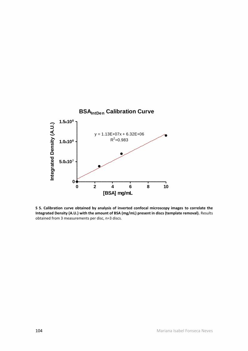
104 Mariana Isabel Fonseca Neves
BSAIntDen Calibration Curve
0 2 4 6 8 100
5.0107
1.0108
1.5108
y = 1.13E+07x + 6.32E+06
R2=0.983
[BSA] mg/mL
Inte
gra
ted
Den
sit
y (
A.U
.)
S 5. Calibration curve obtained by analysis of inverted confocal microscopy images to correlate the Integrated Density (A.U.) with the amount of BSA (mg/mL) present in discs (template removal). Results obtained from 3 measurements per disc, n=3 discs.

Mariana Isabel Fonseca Neves 105
ALMA 51% BSA solution
0
20
40
60
mB
SA
/md
isc (
ug
/mg
)
ALMA 71% BSA solution
0
20
40
60
mB
SA
/md
isc (
ug
/mg
)
NIP
MIP
S 6. Amount of BSA present in ALMA5 and ALMA 7 NIP and MIP discs after 72h incubation in 1% BSA solution in 0.9% NaCl (pH 4.2). Data obtained by protein quantification in supernatant, bars represent mean values of n=3 discs ± SD.

106 Mariana Isabel Fonseca Neves
BSAIntDen Calibration Curve
0 2 4 6 8 100
2.0107
4.0107
6.0107
y = 5.21E+06x + 2.76E+06
R2
= 0.987
[BSA] mg/mL
Inte
gra
ted
Den
sit
y (
A.U
.)
S 7. Calibration curve obtained by analysis of inverted confocal microscopy images to correlate the Integrated Density (A.U.) with the amount of BSA (mg/mL) present in discs (rebind assay). Results obtained from 3 measurements per disc, n=3 discs.