molecular quantum-dot cellular automata (qca): … · center for nano science and technology craig...
TRANSCRIPT
Center for Nano Science and Technology
Craig S. LentUniversity of Notre Dame
Molecular Quantum-dot Cellular Automata (QCA): Beyond
Transistors
Supported by National Science Foundation
ND Collaborators: Greg Snider, Peter Kogge, Mike Niemier, Marya Lieberman, Thomas Fehlner, Alex Kandel,Alexei Orlov, Mo Liu,Yuhui Lu
Center for Nano Science and Technology
Outline of presentation• Introduction and motivation• QCA paradigm• QCA implementations
– Metal-dot– Semiconductor-dot– Magnetic– Molecular
• Circuit and system architecture• Summary
Center for Nano Science and Technology
Goal: Electronics at the single-molecule scale

Center for Nano Science and Technology
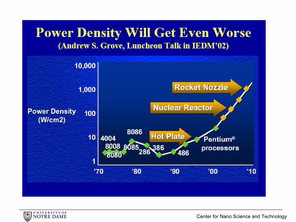
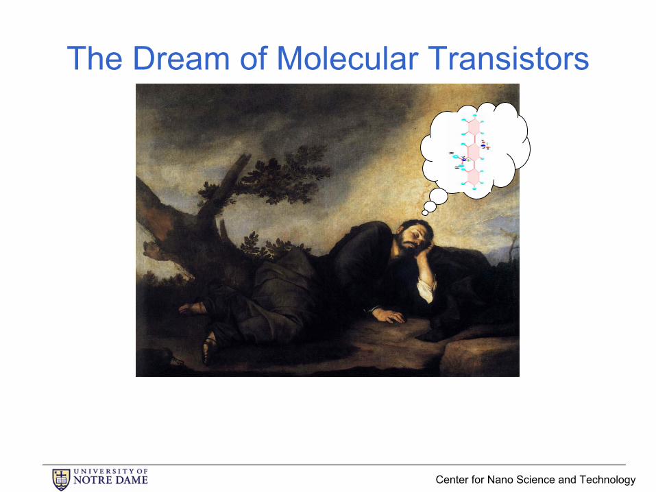
The Dream of Molecular Transistors
Why don’t we keep on shrinking transistors until they are each a single molecule?

Center for Nano Science and Technology
Dream molecular transistors
V
off
low conductance state
V
high conductance state
on I
1 nm
fmax=1 THz
Molecular densities: 1nm x 1nm 1014/cm2

Center for Nano Science and Technology
Transistors at molecular densitiesSuppose in each clock cycle a single electron moves from power supply (1V) to ground.
V
Frequency (Hz) 1014 devices/cm2 1013 devices/cm2 1012 devices/cm2 1011 devices/cm2
1012 16,000,000 1,600,000 160,000 16,000
1011 1,600,000 160,000 16,000 1,600
1010 160,000 16,000 1,600 160
109 16,000 1600 160 16108 1600 160 16 1.6107 160 16 1.6 0.16106 16 1.6 0.16 0.016
Power dissipation (Watts/cm2)
ITRS roadmap: 7nm gate length, 109 logic transistors/cm2 @ 3x10¹⁰ Hz for 2016
Center for Nano Science and Technology
Center for Nano Science and Technology
The Dream of Molecular Transistors
Center for Nano Science and Technology
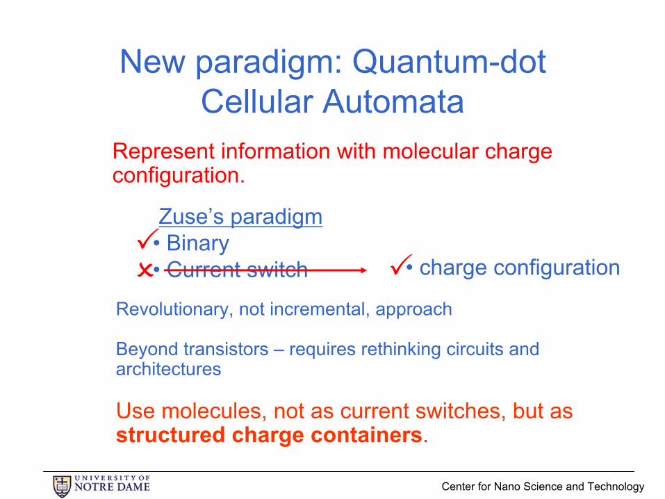
New paradigm: Quantum-dot Cellular Automata
Revolutionary, not incremental, approach
Beyond transistors – requires rethinking circuits and architectures
Use molecules, not as current switches, but as structured charge containers.
Represent information with molecular charge configuration.
Zuse’s paradigm• Binary• Current switch • charge configuration
Center for Nano Science and Technology
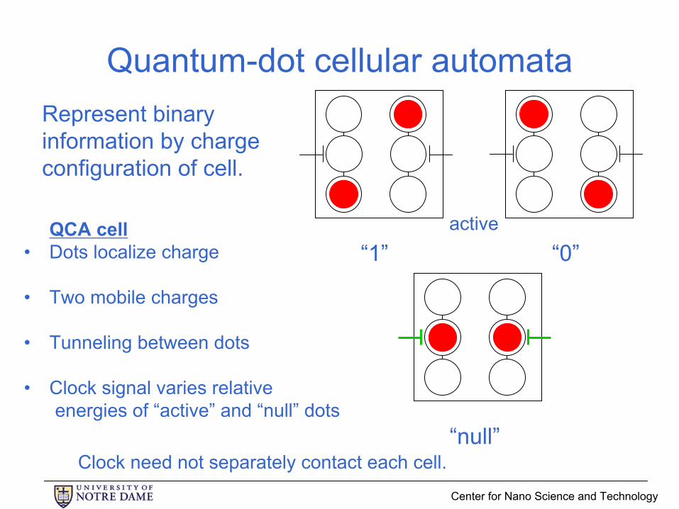
Quantum-dot cellular automataRepresent binary information by charge configuration of cell.
“0”
“null”
“1”QCA cell
• Dots localize charge
• Two mobile charges
• Tunneling between dots
• Clock signal varies relativeenergies of “active” and “null” dots
active
Clock need not separately contact each cell.

Center for Nano Science and Technology
“null”
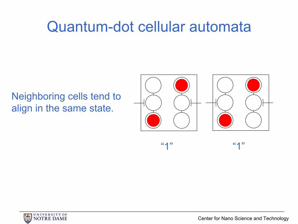
Quantum-dot cellular automata
Neighboring cells tend to align in the same state.
“1”
Center for Nano Science and Technology
Quantum-dot cellular automata
Neighboring cells tend to align in the same state.
“1” “1”

Center for Nano Science and Technology
Quantum-dot cellular automata
Neighboring cells tend to align in the same state.
“1” “1”
This is the COPY operation.

Center for Nano Science and Technology
QCA cell-cell response function
Neighbor Polarization Neighbor Polarization
Cel
l Pol
ariz
atio
n
Cel
l Pol
ariz
atio
nClock: off Clock: on

Center for Nano Science and Technology
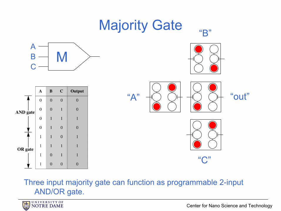
Majority Gate
“1”
“1”
“0”
“null”

Center for Nano Science and Technology
Majority Gate
“1”
“1”
“0”
“1”
Center for Nano Science and Technology
Majority Gate
Three input majority gate can function as programmable 2-input AND/OR gate.
“A”
“C”
“B”
“out”
MABC

Center for Nano Science and Technology
QCA single-bit full adder
Hierarchical layout and design are possible.Simple-12 microprocessor (Kogge & Niemier)
result of SC-HF calculation with site model
Center for Nano Science and Technology
Outline of presentation• Introduction and motivation• QCA paradigm• QCA implementations
– Metal-dot– Semiconductor-dot– Magnetic– Molecular
• Circuit and system architecture• Summary
Center for Nano Science and Technology
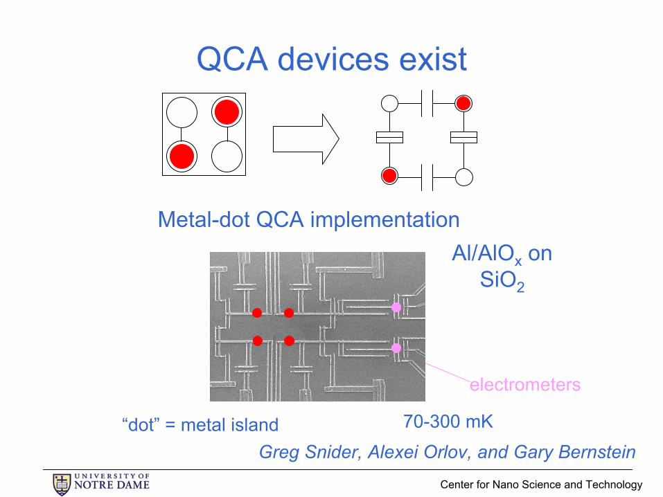
QCA devices exist
“dot” = metal island
electrometers
70-300 mK
Al/AlOx on SiO2
Metal-dot QCA implementation
Greg Snider, Alexei Orlov, and Gary Bernstein
Center for Nano Science and Technology
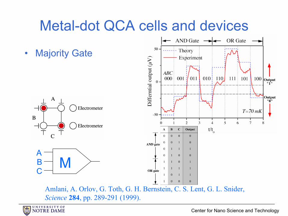
Metal-dot QCA cells and devices
• Majority Gate
MABC
Amlani, A. Orlov, G. Toth, G. H. Bernstein, C. S. Lent, G. L. Snider, Science 284, pp. 289-291 (1999).
Center for Nano Science and Technology
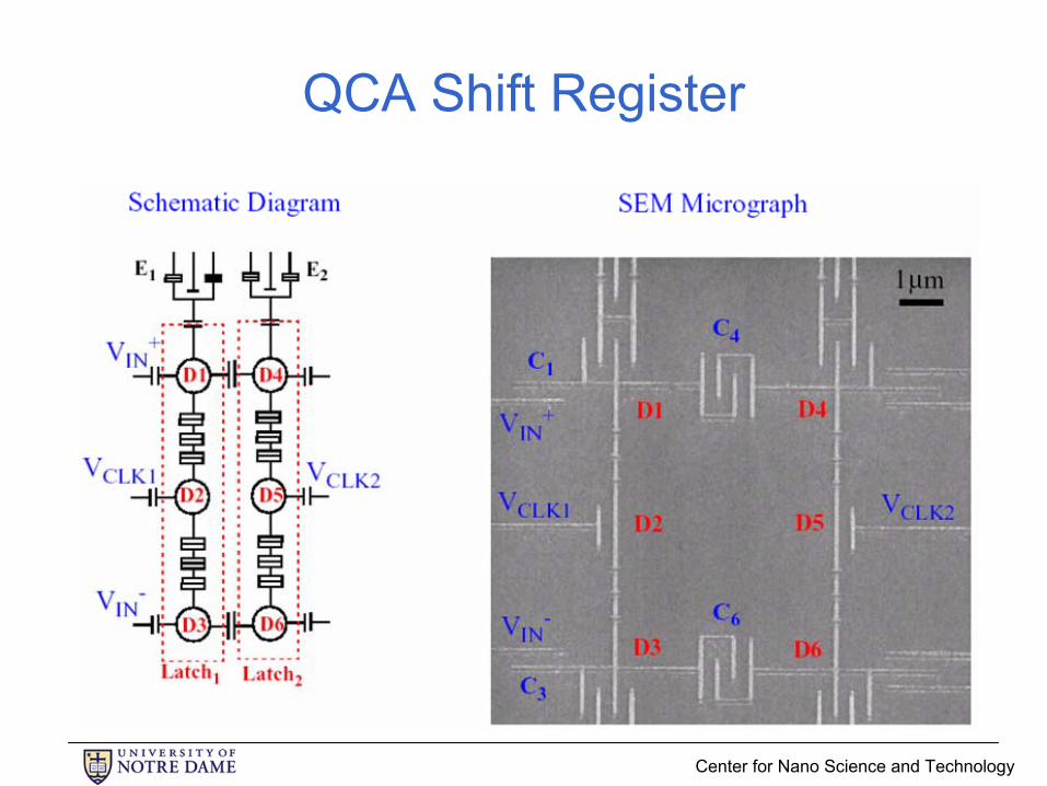
QCA Shift Register
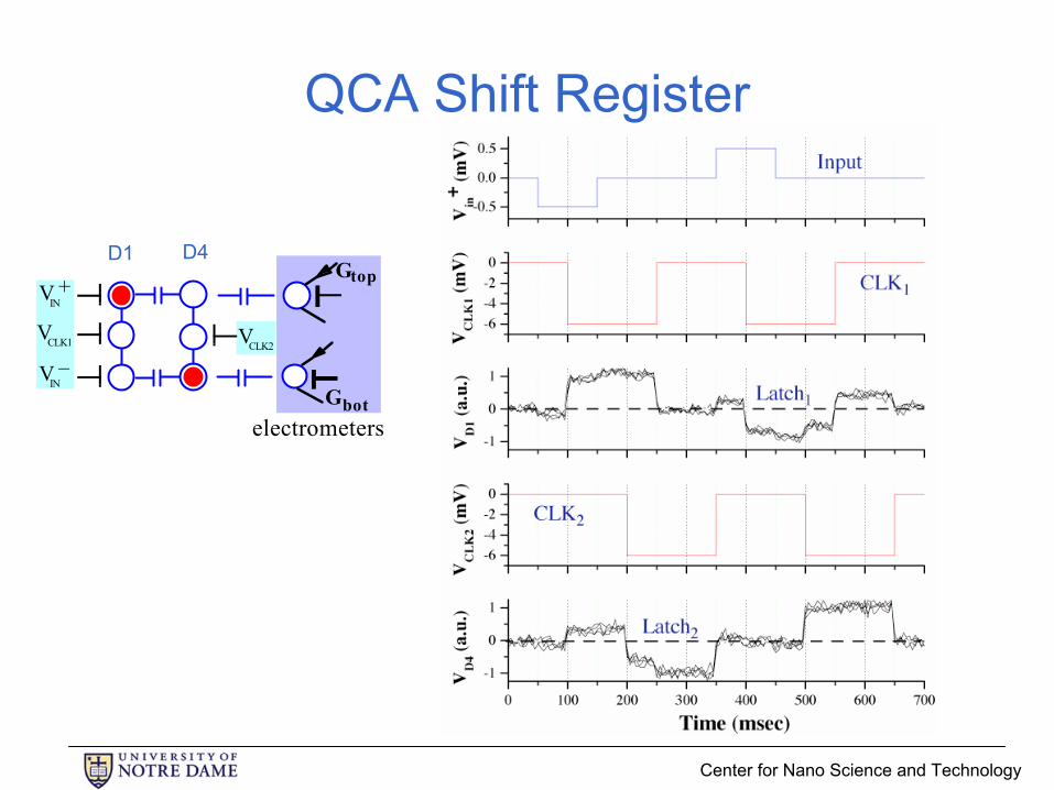
Center for Nano Science and Technology
QCA Shift Register
Gtop
Gbotelectrometers
VIN+
VIN–
VCLK1 VCLK2
D1 D4

Center for Nano Science and Technology
Metal-dot QCA devices exist
• Single electron analogue of molecular QCA• Gates and circuits:
– Wires– Shift registers– Fan-out– Power gain demonstrated– AND, OR, Majority gates
• Work underway to raise operating temperatures
Center for Nano Science and Technology
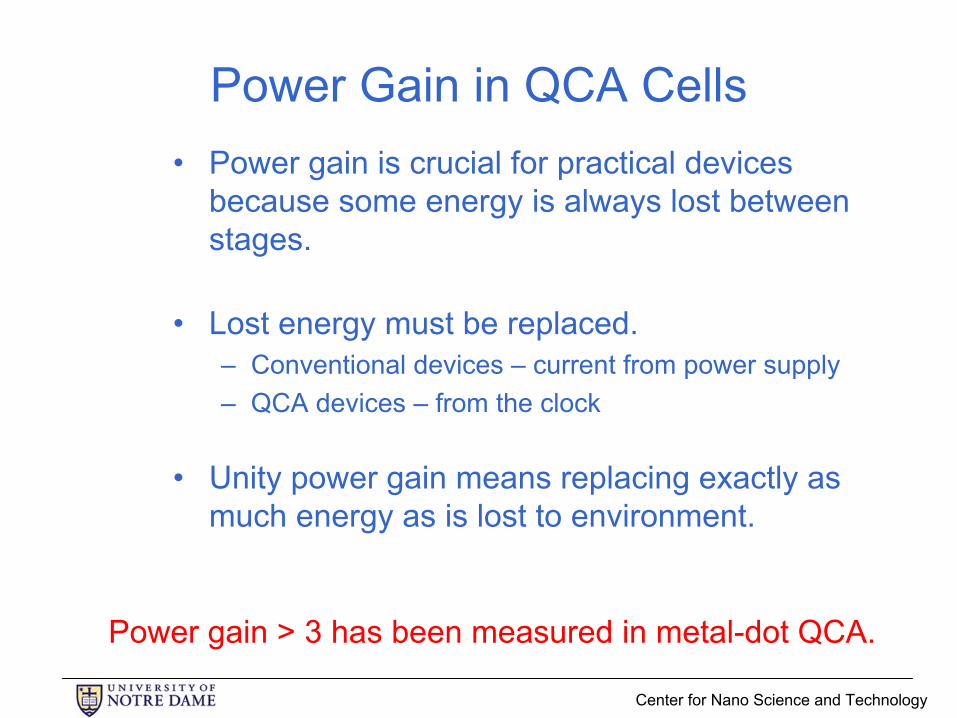
Power Gain in QCA Cells• Power gain is crucial for practical devices
because some energy is always lost between stages.
• Lost energy must be replaced.– Conventional devices – current from power supply– QCA devices – from the clock
• Unity power gain means replacing exactly as much energy as is lost to environment.
Power gain > 3 has been measured in metal-dot QCA.

Center for Nano Science and Technology
GaAs-AlGaAs QCA cell
• Dots defined by top gates depleting 2DEG
• Direct measurement of cell switching
Center for Nano Science and Technology
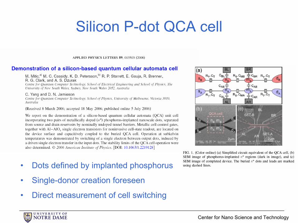
Silicon P-dot QCA cell
• Dots defined by implanted phosphorus
• Single-donor creation foreseen
• Direct measurement of cell switching

Center for Nano Science and Technology
Magnetic QCA
• Dots defined by magnetic domains
• Room temperature operation
Center for Nano Science and Technology
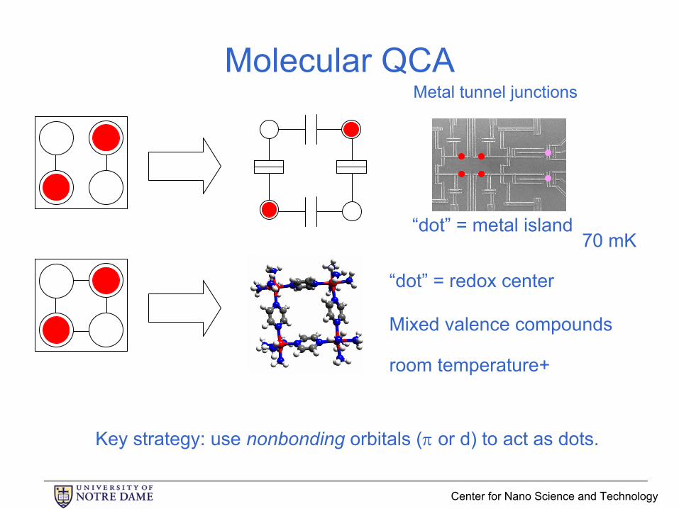
Molecular QCA
“dot” = metal island70 mK
Mixed valence compounds
“dot” = redox center
room temperature+
Metal tunnel junctions
Key strategy: use nonbonding orbitals (π or d) to act as dots.
Center for Nano Science and Technology
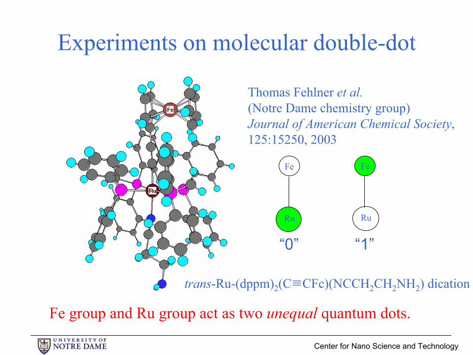
Experiments on molecular double-dot
Thomas Fehlner et al. (Notre Dame chemistry group)Journal of American Chemical Society,125:15250, 2003
Ru Ru
Fe Fe
“0” “1”
Fe group and Ru group act as two unequal quantum dots.
trans-Ru-(dppm)2(C≡CFc)(NCCH2CH2NH2) dication

Center for Nano Science and Technology
Surface attachment and orientation
N
Si Si3.8 Α
2.4 Α106o
PHENYL GROUPS“TOUCHING” SILICON
Molecule is covalent bonded to Si and oriented vertically by “struts.”
Si(111)
molecule Si-N bonds
“struts”
Center for Nano Science and Technology
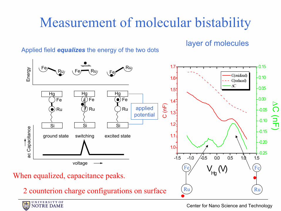
FeRu Fe Ru Fe
Ru
Si
HgFe
Ru
Si
HgFe
Ru
Si
HgFe
Ru
ac C
apac
itanc
e
voltage
excited stateswitching
Ener
gy
ground state
Applied field equalizes the energy of the two dots
When equalized, capacitance peaks.
appliedpotential
Measurement of molecular bistability
-1.5 -1.0 -0.5 0.0 0.5 1.0 1.5
1.0
1.1
1.2
1.3
1.4
1.5
1.6
1.7
C(oxidized) C(reduced) ∆C
VHg (V)C
(nF)
-0.25
-0.20
-0.15
-0.10
-0.05
0.00
0.05
0.10
0.15
∆C (nF)
layer of molecules
Ru
Fe
Ru
Fe
2 counterion charge configurations on surface

Center for Nano Science and Technology
Longer molecular double-dot
Isopotentialsurface
HOMO orbital
Center for Nano Science and Technology
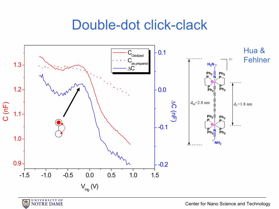
Double-dot click-clack
-1.5 -1.0 -0.5 0.0 0.5 1.0 1.5
0.9
1.0
1.1
1.2
1.3
COxidized Cas prepared ∆C
VHg (V)
C (n
F)
-0.2
-0.1
0.0
0.1
∆C (nF)
Ph2P
RuPPh2
Ph2P
PPh2
Ph2P
RuPPh2
Ph2P
PPh2
N
N
H2N
NH2
3+
d1=1.8 nmdm=2.8 nm
Hua & Fehlner

Center for Nano Science and Technology
Square 4-dot QCA molecules
0.6 nm

Center for Nano Science and Technology
Imaging molecular double-dot
structure toluene solution Goal: single-molecule imaging on surfaces
Kandel group
Molecules are pulse-injected from solution into vacuum onto a clean, crystalline gold [Au(111)] surface.
Ru-Ru molecule with no surface binding. Not mixed-valence species.

Center for Nano Science and Technology
Ru2 clusteringSome clustering and alignment of molecules occurs automatically during deposition. (50 nm image shown.)
We should be able to compare isolated molecules with those in larger clusters.
Experimental conditions: 0.5 V, 20 pA, 298 K

Center for Nano Science and Technology
Molecular motion
Changing tunneling conditions (from 1.0 V, 20 pA to 1.0 V, 100 pA) increases tip/molecule interaction.
We observe a change in orientation for one Ru2 molecule.
This suggests the possibility of using the STM tip for controlled manipulation of these molecules on the surface.
Experimental conditions: 250 ×180 Å, 1.0 V, 20 (100) pA, 298 K
Center for Nano Science and Technology
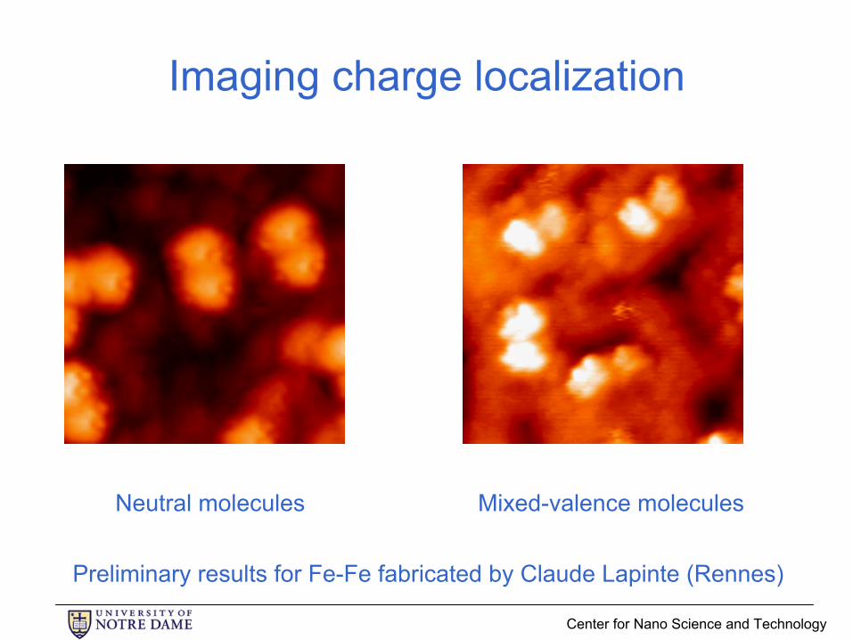
Imaging charge localization
Neutral molecules Mixed-valence molecules
Preliminary results for Fe-Fe fabricated by Claude Lapinte (Rennes)

Center for Nano Science and Technology
Single-atom quantum dots

Center for Nano Science and Technology
Outline of presentation• Introduction and motivation• QCA paradigm• QCA implementations
– Metal-dot– Semiconductor-dot– Magnetic– Molecular
• Circuit and system architecture• Summary
Center for Nano Science and Technology
Field-clocking of QCA wire: shift-register

Center for Nano Science and Technology
Computational wave: majority gate
Center for Nano Science and Technology
Computational wave: adder back-end
Center for Nano Science and Technology
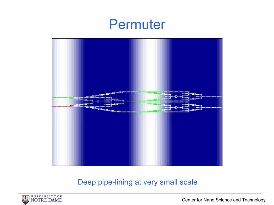
Permuter
Deep pipe-lining at very small scale

Center for Nano Science and Technology
Wider QCA wires
Redundancy results in defect tolerance.
Center for Nano Science and Technology
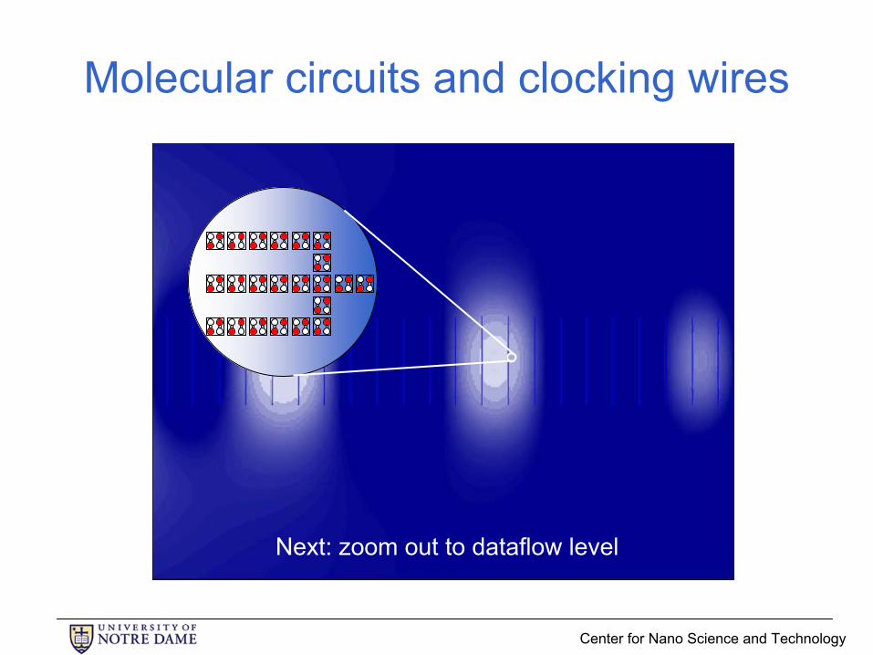
Molecular circuits and clocking wires
Next: zoom out to dataflow level
Center for Nano Science and Technology
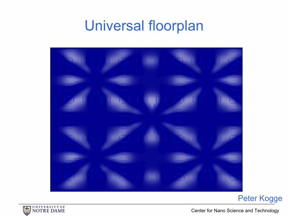
Universal floorplan
Peter Kogge

Center for Nano Science and Technology
QCA design tools
Design tools are starting to enable new systems ideas.
QCADesigner
Konrad WalusU. British Columbia
Center for Nano Science and Technology
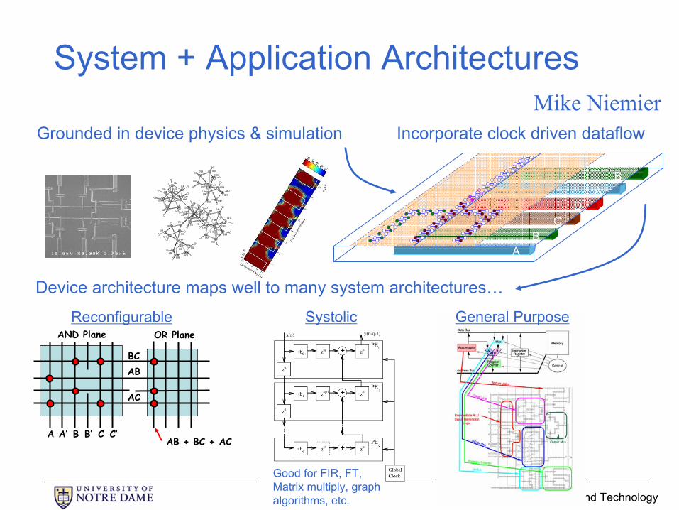
System + Application Architectures
Grounded in device physics & simulation Incorporate clock driven dataflow
AB
CD
AB
Device architecture maps well to many system architectures…
A A’ B B’ C C’
AB
AC
AND Plane OR Plane
AB + BC + AC
BC
Reconfigurable General PurposeSystolic
Good for FIR, FT, Matrix multiply, graph algorithms, etc.
Mike Niemier

Center for Nano Science and Technology

Center for Nano Science and Technology
Center for Nano Science and Technology
Center for Nano Science and Technology

Center for Nano Science and Technology
Summary
• QCA offers possible path to limits of downscaling –molecular computing.– General-purpose computing– New architecture– Low power dissipation which is essential
• Single-electron metal-dot QCA devices exist.• First steps in molecular-scale QCA• Clear path but much research remains to be done.
– Rethinking architecture to match problem– Chemistry, physics, electrical engineering, computer science
Thanks for your attention.