moldboard plows - gearmore parts breakdown ... the moldboard plow assembly and proper installation...
TRANSCRIPT

MOLDBOARD
PLOWS
ASSEMBLY, PARTS
& OPERATOR'S MANUAL
FOR MODELS
MP1-14-LC & MP2-14-LC
March 2007
Form: MPMoldbrdPlow.pm7

1 Introduction............................................................. 1 1.1 General Information .............................................. 22 Safety ....................................................................... 3 2.1 Training ................................................................. 4 2.2 Preparation ........................................................... 4 2.3 Operational Safety ................................................ 5 2.4 Maintenance Safety .............................................. 5 2.5 Transporting Safety .............................................. 5 2.6 Storage Safety ...................................................... 6 2.7 Safety Decals........................................................ 63 Assembly ................................................................. 7 3.1 General ................................................................. 7 3.2 3-Point Hitch Assembly ......................................... 7 3.3 Optional Coulter Kit Assy. ..................................... 74 Operation ................................................................ 8 4.1 Operation Safety................................................... 8 4.2 Before Operation .................................................. 8 4.3 Attaching ............................................................... 8 4.4 Transporting.......................................................... 8 4.5 Adjustments .......................................................... 9 4.6 Operation .............................................................10 4.7 Operating Hints ....................................................105 Service and Maintenance ......................................11 5.1 Maintenance ........................................................11 5.2 Shearbolt Replacement ....................................... 11 5.3 Lubrication ........................................................... 11 5.4 Detaching .............................................................11 5.5 Storage ................................................................116 Troubleshooting .............................................. 12-137 Specifications ........................................................14 7.1 Bolt Torque ..........................................................148 Parts Breakdown ...................................................15 8.1 One Bottom - Plow Frame Components..............15 8.2 Two Bottom - Plow Frame Components ..............16 8.3 Plow Bottom Components ...................................17 8.4 Rolling Coulter Components ................................189 Limited Warranty ...................................................19
TABLE OF CONTENTS
SECTION DESCRIPTION PAGE

1
1 INTRODUCTION
This manual covers the assembly, operation, and maintenance of your Series MP Moldboard Plow.Studying and obeying these instructions will insure optimum product performance and longevity. Besure to read all instructions carefully. Read all safety precautions prior to operation.
The moldboard plow is designed as a primary tillage tool for turning over soil. They work well forburying trash and aerating the soil.
Maintain your implement with original repair parts to insure optimum performance.
It is the policy of the manufacturer to improve its products whenever possible and practical. Wereserve the right to make changes, improvements, and modifications at any time without incurringthe obligation to make such changes, improvements, and modifications on any implement soldpreviously.
TO THE DEALER:
The moldboard plow assembly and proper installation to the tractor is the responsibility of thedealer. Read manual instructions and safety rules. Make sure all items on the pre-delivery and deliverycheck lists are completed before releasing equipment to the owner.
TO THE OWNER:
Read this manual before operating your moldboard plow. The information presented will prepareyou to do a better and safer job. Keep this manual handy for ready reference. Require all operators toread this manual carefully and become acquainted with all the adjustment and operating proceduresbefore attempting to operate. Replacement manuals can be obtained from your dealer.
The moldboard plow you have purchased has been carefully engineered and manufactured to providedependable and satisfactory use. Like all mechanical products, it will require cleaning and upkeep.Lubricate the unit as specified. Observe all safety information in this manual and safety decals on themoldboard plow and tractor.
For service, your authorized dealer has trained mechanics, genuine service parts, and the necessarytools and equipment to handle all your needs.
Provide this information to your dealer to obtain correct repair parts.
OPERATOR ORIENTATION - The directions left, right, front and rear, as mentionedthroughout this manual, are as seen from the driver's seat and facing in the direction of travel.

2
1.1 GENERAL INFORMATION
Read this manual carefully to learn how to properly operate and service your moldboard plowcorrectly. Failure to do so could result in personal injury or equipment damage.
Throughout this manual references are made to right and left direction. RIGHT - HAND ANDLEFT - HAND sides are determined by standing behind the plow facing the direction the plow willtravel when going forward.
The purpose of this manual is to assist you in operating and maintaining your moldboard plow. Readit carefully. It furnishes information and instructions that will help you achieve years of dependableperformance. These instructions have been compiled from extensive field experience and engineeringdata. Some information may be general in nature due to unknown and varying operating conditions.However, through experience and these instructions, you should be able to develop proceduressuitable to your particular situation.
Maintain your moldboard plow with original equipment repair parts to ensure optimumperformance.
The illustrations and data used in this manual were current at the time of printing, but due topossible production changes, your machine may vary slightly in detail. We reserve the right toredesign and change the machines as may be necessary without notification.
CUSTOMER INFORMATION:
Name: ____________________________________________
Purchased From: ____________________________________
Date Purchased: _____________________________________
Model No: _________________________________________
Serial No: _________________________________________

2 SAFETYSAFETY ALERT SYMBOL
Why is SAFETY important to you?
The Safety Alert symbol identifiesimportant safety messages on theGearmore Seeder/Spreader and in themanual. When you see this symbol,be alert to the possibility of personalinjury or death. Follow the instruc-tions in the safety message.
This Safety Alert symbol meansATTENTION! BECOME ALERT!YOUR SAFETY IS INVOLVED!
Accidents Disable and KillAccidents CostAccidents Can Be Avoided
3 Big Reasons
WARNING - Indicates a potentially hazard-
DANGER - Indicates an imminently hazardous
CAUTION - Indicates a potentially hazardoussituation that, if not avoided, mayresult in minor or moderate injury.It may also be used to alert againstunsafe practices.
ous situation that, if not avoided,could result in death or seriousinjury, and includes hazards that areexposed when guards are removed.It may also be used to alert againstunsafe practices.
situation that, if not avoided, willresult in death or serious injury.This signal word is to be limited tothe most extreme situations typi-cally for machine componentswhich, for functional purposes,cannot be guarded.
SIGNAL WORDS:
Note the use of the signal words DANGER,WARNING and CAUTION with the safetymessages. The appropriate signal word foreach message has been selected using thefollowing guide-lines:
If you have any questions not answered in this manual or require additional copies or the manual isdamaged, please contact your dealer.
SI NO LEE INGLES, PIDA AYUDAA AIGUIEN QUE SI LO LEA PARAQUE LE TRADUZCA LASMIDIDAS DE SEGURIDAD.
3

2.2 PREPARATION
1. Always wear closefitting clothing andpersonal protectionequipment calledfor by the jobconditions. Theseitems may include ahard hat, safetyglasses, goggles or face shield, hearingprotection, and safety boots. DO NOT wearloose clothing, jewelry or any other items thatmay be entangled in moving parts. Tie up longhair.
2. Ensure implement is properly mounted,adjusted and in good operating condition.
3. Tighten all bolts and nuts and check that allcotter pins are installed securely to ensureequipment is properly assembled beforeoperating.
4. Tractor must be equipped with ROPS FRAMEor ROPS CAB and seat belt. Keep seat beltsecurely fastened. Falling off tractor can resultin death from being run over or crushed. Keepfoldable ROPS systems in "locked up" positionat all times.
5. Remove accumulated debris from thisequipment, tractor, and engine to avoid firehazard.
6. Ensure all safety decals are installed. Replace ifdamaged. (See Safety Decals section forlocation.)
7. Ensure shields and guards are properly installedand in good condition. Replace if damaged.
8. A minimum 20% of the combined tractor andplow weight must be on tractor front wheelswith plow in transport position. Without thisweight, tractor could tip over causing personalinjury or death. See your tractor operatorsmanual for information regarding addingweights.
1. Safety instructions are important! Read thismanual and the tractor manual; follow all safetyrules and safety decal information.(Replacement manuals are available from yourdealer) Failure to follow instructions or safetyrules can result in serious injury or death.
2. If you do not understand any part of thismanual and need assistance, see your dealer.
3. Know your controls and how to stop engineand attachment quickly in an emergency.
4. The operator must be instructed in and becapable of the proper operation of theequipment, its attachments and all controls. Donot allow anyone to operate this equipmentwithout proper instructions.
5. Do not allow children or untrained persons tooperate equipment.
4
2.1 TRAINING
Your personal safety is a primary concern in thedesign and manufacture of our products. Ourefforts to provide such equipment can be wiped outby a single careless act of an operator.
In addition to the design and configuration ofequipment, hazard control and accident preventionare dependent upon the awareness, concern,prudence, and proper training o fpersonnel involvedin the operation, transport, maintenance and storageof equipment.
It has been said "The best safety device is aninformed, careful operator." We ask you to bethat kind of an operator.
The design of this equipment depends on it beingoperated within the limitations as explained in thismanual.
SAFETY RULESATTENTION! BECOME ALERT! YOUR SAFETY IS INVOLVED!

5
2.3 OPERATIONAL SAFETY
Keep bystanders away from equipmentwhile it is in operation.
Operate only in daylight or good artificiallight.
Always comply with all state and locallighting and marking requirements.
Use caution when working around sharpobjects such as shares, coulter blades,tines, etc.
No riders are allowed on equipment.
Always sit in tractor seat with seat beltfastened when operating controls orstarting engine. Place transmission in parkor neutral, engage brake and ensure allother controls are disengaged beforestarting tractor engine.
Look down and to the rear and make surearea is clear before operating in reverse.
Do not operate on steep slopes.
Do not stop, start or change directionssuddenly on slopes
Use extreme care and reduce ground speedon slopes and rough terrain.
Watch for hidden hazards on the terrainduring operation.
Stop tractor and implement immediatelyupon striking an obstruction. Turn offengine, remove key, inspect and repair anydamage before resuming operation.
When performing any service ormaintenance, disengage power toimplement. Lower all raised components tothe ground. Operate valve levers to releaseany hydraulic pressure. Stop engine, setparking brake and remove key beforedismounting tractor.
2.4 MAINTENANCE SAFETY
Before working underneath, raise moldboardplow to highest position and block securely.Blocking up prevents moldboard plow droppingfrom hydraulic leak down, hydraulic systemfailures, or mechanical failure on the tractor.
Keep all persons away from operator controlarea while performing adjustments, service ormaintenance.
Frequently check plow shares. They should besharp, free of nicks and cracks and securelyfastened.
Do not handle plow shares with bare hands.Careless or improper handling may result inserious injury.
Your dealer can supply genuine replacementplow shares. Substitute plow shares may notmeet original equipment specifications.
2.5 TRANSPORTING SAFETY
Use a slow-moving-vehicle (SMV) emblem andproper lighting on the tractor when transportingthe moldboard plow.
Do not transport the plow over 20 MPH (30 KPH)on the best surface conditions. Reduce speedwhen going up or down hills and whenapproaching ditches or corners.
Always comply with all state and local lightingand marking requirements.
Raise plow to highest position for transport.
Keep your plow in proper working condition.Unauthorized modifications to the plow mayimpair the function, affect plow life, and put youat risk. Do not add excessive weight to plow.Additional weight could cause frame to failresulting in loss of control of plow/tractor duringtransport.
Watch low hanging overhead power lines duringtransport. Avoid contact as this can causeserious injury or death.

2.6 STORAGE
1. Lower plow to the ground for storage andblock to prevent rolling.
2. Store on a level surface sheltered from theweather.
3. Coat soil engaging surfaces with a rustinhibitor after cleaning.
4. Keep playing children and bystandersaway from storage area.
REPLACE IMMEDIATELY ANY
DAMAGED SAFETY DECALS
The following safety decals are located on yourimplement. Read them and follow theirinstructions. Keep all decals in place and legible.Replace worn or missing decals. Replacementsafety decals are available through your dealer.Order by number listed.
6
2.7 SAFETY DECALS
SAFETY DECALSATTENTION! BECOME ALERT!YOUR SAFETY IS INVOLVED!
How to Install Safety Signs:
• Be sure that the installation area is clean anddry.
• Be sure temperature is above 50°F (10°C).
• Determine exact position before you removethe backing paper.
• Remove the smallest portion of the splitbacking paper.
• Align the sign over the specified area andcarefully press the small portion with theexposed sticky backing in place.
• Slowly peel back the remaining paper andcarefully smooth the remaining portion of thesign in place.
• Small air pockets can be pierced with a pinand smoothed out using the piece of signbacking paper.
Part No. 029770 Amber ReflectorLocated front outside corner of frame
Part No. 029771 Red ReflectorLocated rear outside corner of frame

7
3 ASSEMBLY
3.1 GENERAL
Your Series MP Moldboard Plow is shippedpartially assembled. Choose a level area toarrange the parts conveniently. Assemble partsfor each step loosely to insure fit. Useflatwashers with slotted holes. Always uselockwashers unless a lock nut is called for.Tighten hardware after parts are installedaccording to the torque chart given on Page 14.Unless otherwise stated, all hardware is Grade5. The following assembly steps are given tominimize the need for adjustment afterassembly. Remember that LEFT and RIGHTare determined by standing at the rear of theimplement and facing it.
The moldboard plow 3-point hitch assembly isshipped inverted for packaging shipment.
1. Stand the plow upright and block the framesecurely to support the plow and keep itfrom moving.
2. Remove top nut, bolt, spacer, and pull lugfrom A-frame. Loosen nut holding other endof pull lug to plow frame.
3. Remove the (4) nuts, (2) angle irons, and (4)bolts from front frame area. Turn theassembly upside down and install on top offrame rails. Put angle iron, bolts and nutsback on.
4. Install pull lug and spacer removedpreviously in A-frame and install bolt andnut in second hole from top. Tighten bolt onplow frame at other end of pull lug.
3.2 3-POINT HITCH ASSEMBLY
3.3 OPTIONAL COULTER KIT ASSY.(SEE FIG. 3)
Rolling coulters are used to make plowingsmoother and neater. Coulters also reduce thedrag, thereby reducing power required.
Mount the coulter assembly on the beam in frontof the plow bottom. It can be mounted on eitherside of the beam to aid in lateral adjustment.
1. Stand the plow upright and block the framesecurely to support the plow and keep it frommoving.
2. Install u-bolts through coulter plate and puton lockwasher and nut. Slip u-bolts andcoulter plate over plow beam.
3. Slide coulter stem up from bottom throughthe u-bolts. Snug the nuts to keep the coulterstem from dropping.
4. Move coulter to desired position and torquethe nuts.
5. Remove the blocks or safety stands.
Fig. 3 - Frame Components

8
4 OPERATION
4.1 OPERATION SAFETY
Your personal safety is a primary concern in thedesign and manufacture of our products. Ourefforts to provide such equipment can be wipedout by a single careless act of an operator.
In addition to the design and configuration ofequipment, hazard control and accidentprevention are dependent upon the awareness,concern, prudence and proper training ofpersonnel involved in the operation, transport,maintenance and storage of equipment.
It had been said "The best safety device is aninformed, careful operator." We ask you to bethat kind of an operator.
The operator is responsible for the properoperation of this moldboard plow. The operatormust be properly trained. Operators should befamiliar with the moldboard plow and tractor andall safety practices before starting operation.Read the safety information on pages 3-6
TRACTOR STABILITY (Fig. 5)
A minimum 20% of combined tractor andplow weight must be on tractor front wheelswith attachment in transport position.Without this weight, tractor could tip overcausing personal injury or death. See yourtractor operators manual regarding addingweights.
WARNING
Fig. 5
4.2 BEFORE OPERATION
1. Tighten all loose hardware using thetorque chart on page 14. SEE ASSEMBLY.Replace any missing hardware. On newmachines, all hardware must be recheckedafter first few hours of operation.
2. Replace any bent or broken parts.
3. Refer to your Tractor's Owner's Manualfor recommended adjustments and weightdistribution.
4. Read the SAFETY section of this manualto be sure of all precautions.
4.3 ATTACHING
1. Back tractor to align lower link arms withplow link pins.
Be sure bystanders are clear. Do not standbetween plow and tractor. Shut off tractorand engage parking brake prior todismounting.
2. Connect lower link arms to plow using linkpins provided. Secure with click pins.
3. Connect top link to implement using a pin.Secure with click pins. Adjust top link soplow bottom sits flat on floor.
WARNING
4.4 TRANSPORTING
1. Transport plow lifted high above ground.
2. Travel at a speed suitable for terrain andother conditions. Transport at speedscompatible with safety and no more than20 MPH (30 KPH). Use care whentransporting on rough terrain.
3. Avoid night travel on public roads. Ifunavoidable, be sure to use adequatelighting on tractor and implement. Alwayshave a slow moving vehicle (SMV) emblemattached to the implement clearly visiblefrom the rear. Check local laws regardingtransport on public roads.

9
4.5 ADJUSTMENTSPLOW DRAWBAR ADJUSTMENTThe plow share on the right hand furrow must bealigned next to the furrow in order to do a cleanjob.
It is recommended that the tractor rear wheelsbe set so the right hand tire runs in the previousfurrow.
In order to trail properly with a minimum effecton tractor steering, it is necessary to adjust thedrawbar so that the plow is pulling as close to thetractor centerline as possible. Refer to the tablebelow and fig. 6, dimension A. Note that for onebottom plows in particular, the ideal wheel treadwidth is too narrow for most tractors to obtain.In those cases, set the width as narrow aspossible.
Loosen the u-bolt nuts holding the frame to thefront cross frame and front angles and slidedrawbar as necessary. Torque the u-bolt nutswhen completed.
The right hand 3-point mounting pin can belocated in three position. You can use it to affectplow trailing.
Fig. 6 - Drawbar Setting
SIDE TO SIDE LEVELINGThe plow should be leveled from side to side. Withthe plow in the ground and tractor right tire in thefurrow, use the tractor's link arm crank to adjustthe lower link arm up or down as needed to level theplow frame. The plow should be level in the workingposition.
FRONT TO REAR LEVELINGThe plow is leveled front to rear by adjusting thelength of the top link of the 3-point hitch. Shortenthe top link to tilt the plow forward, and lengthenthe top link to tilt the plow backward.
OPTIONAL COULTER ADJUSTMENTThe rolling coulter outlines the cut of the plowbottom. It cuts through sod and surface trash, aidsin securing clean, uniform furrows, reduces draftand lessens wear of the plow bottom. The coultershould be 1 to 2 inches from the moldboard for thebest results.
Adjust the coulter laterally by loosening the u-boltsand twisting the coulter shaft. Height adjustmentis made simply by raising or lowering the coultershaft. Be sure to tighten u-bolt nuts afteradjustment is completed.
WIDTH OF CUTThe rolling coulter should only be positioned farenough to the left of the landslide to allow a clean,straight furrow wall. For average conditions, setthe coulter blade between 1/2" and 5/8" to the leftof the landslide. Loose ground and tough scouringconditions will sometimes require the coulter to beset a little wider.
DEPTH OF CUTThe rolling coulter should be set deep enough to cuttrash and leave a clean furrow wall. It should notrun too deep or it will push trash and not cut it.
TRACTOR 3-POINT STABILIZERSInstall the lift arm stabilizer or shorten the stopchains to place the arms into the "non-sway"configuration. Refer to the tractor operatorsmanual for details.
Model Drawbar Setting "A" Ideal Pull Point* Tire Tread (inside of tire)12" One Bottom 11-1/2" 9" 18" Minimum14" One Bottom 11-1/2" 10-1/2" 21" Minimum
12" Two Bottom 8" 14-3/4" 28-1/2"14" Two Bottom 7-1/4" 17-3/4" 35-1/2"
*Measure from the inside of the tires to the centerline of pull.

10
4.6 OPERATION
ATTACHING1. Back tractor to align lower link arms with
plow link pins.
Be sure bystanders are clear. Do not standbetween plow and tractor. Shut off tractorand engage parking brake prior todismounting.
2. Connect lower link arms to plow using linkpins provided. Secure with click pins.
3. Connect top link to implement using a pin.Secure with click pins. Adjust top link soplow bottom sits flat on ground.
TRACTOR FRONT END BALLASTFront end ballast may be required for stabilityand steering control when weight is transferredto the back tires as the plow is raised. As a generalguide:
• Ballast the tractor (less plow) so thatapproximately 1/3 of the tractor weight ison the front wheels.
• When mounted plow is raised, thereaction on the front wheels should beless than 20% of tractor and plow weight.
• See your tractor operators manualregarding adding weights.
TRACTOR HYDRAULICS• Always set the 3-point hitch in the "float"
mode to allow the plow to follow thecontour of the ground.
• Many newer tractors are equipped with"Load Sensing" hydraulics. It is theresponsibility of the operator to set thetractor hydraulic system to provide"float" on the 3-point hitch. Refer to thetractor operators manual for details.
TRACTOR GROUND SPEED• Plowing speed can vary between 3 and 6
mph (5 and 10 kph) depending on thetrash and soil conditions. It is theresponsibility of the operator to note thecondition of the job being done and set thespeed to obtain a quality plowing job.
WARNING
4.7 OPERATING HINTS
• When starting a new field or working area,space the strike-outs to minimize drivingempty at the field ends. Keep the strike-outs as close to parallel as possible.
• Leave a headland wide enough to allow foreasy turning.
• Set the hitch so the right rear tractor tireruns in the furrow.
• "Scour" the plow in sandy conditions toremove the rust and build-up on themoldboard before starting work. This willreduce power requirements and make ahigher quality job.
• In very hard conditions, it may benecessary to add weight to the plowframe. Do not add more than 75 poundsper bottom.
• Install the optional coulter in heavy trashor ground cover conditions. This will cutthrough the surface material and make aclear path for the moldboard.
• Set the coulter 1 to 2 inches from themoldboard for best results. Vary thespace if the coulter does not cut cleanly.
• Each plow bottom is protected by a 7/16" x3" Grade 5 shear bolt in its pivot frame.The bolt will fail when rocks, stumps,roots, or other obstructions areencountered. Lift the plow, back up andreplace the shear bolt.
• Maintain the landslide and wear plate ingood condition. They stabilize the sideload from the shears going through theground.

11
5 SERVICE AND MAINTENANCE
5.1 MAINTENANCE
1. Thoroughly clean the plow after each use.Coat soil engaging surfaces with oil orother rust inhibitor for storage betweenuses.
2. Check over plow frequently for loose orworn parts. Replace parts as necessary tomaintain product performance and toprevent further damage.
3. The coulter has greasable bearings thatrequire lubrication. Check these coultersperiodically to see that they rotate freely.
4. Keep coulter blades and moldboard cuttingedges sharp at all times.
5. Ground Contacting Components - Whenthe ground contacting components wear,they will have to be replaced. Theseinclude the coulter blade, plow shear, shin,landside, wear plate, and bottom.
Each plow bottom is protected by a 7/16" x 3" Grade5 shear bolt in its pivot frame. The bolt will failwhen rocks, stumps, roots, or other obstructionsare encountered. Lift the plow, back up andreplace the shear bolt.
IMPORTANT!Replacement of the shear bolt with a bolthigher than Grade 5 may result in seriousdamage to plow or injury to operator andvoids the manufacturer warranty.
Clean grease fittings before applying grease. Usea multipurpose, lithium base grease.
5.2 SHEARBOLT REPLACEMENT
5.3 LUBRICATION
5.4 DETACHING
1. Choose a level place to store plow,preferably under shelter.
Shut off tractor, engage brake, andremove key prior to dismounting.
2. Lower plow to ground.
3. For one bottom plows, place support underleft end of drawbar. Plow will tip over if notsupported.
4. Remove top link from plow.
5. Detach lower link arms from plow.
6. Be sure plow is stable.
1. Clean all dirt and debris from plow prior tostorage.
2. Store your plow on a flat surface shelteredfrom the weather.
3. Lower the plow to the ground and block toprevent rolling.
4. For periods of long storage, coat soilengaging surfaces with a rust inhibitor suchas grease or oil. Apply touch up paint toframe where paint is worn or chipped toprevent rusting.
5. Keep playing children and bystanders awayfrom storage area.
WARNING
5.5 STORAGE

12
6 TROUBLE SHOOTING
The principle cause of plowing difficulties is improper adjustments. When you experience problems,do not attempt to make adjustments without consulting this section. Also, when making adjustments,try one adjustment at a time.
PROBLEM: POOR PENETRATION
POSSIBLE CAUSE: POSSIBLE REMEDY:
Insufficient suck Shorten tractor top linkWorn share ReplaceCoulters too deep or too far forward See coulter adjustmentDull counter blade Sharpen or replacePosition of tractor selector levers Refer to tractor's owner's manual for proper settingsGround hard and dry Increase depth of headland starting furrow
PROBLEM: PLOW CROWDING
POSSIBLE CAUSE: POSSIBLE REMEDY:
Plow running on nose Lengthen tractor top linkPlow crowding to the left Front bottom too deep, shorten right-hand leveling screw or
lengthen top linkPlow crowding to the right Front bottom too shallow, lengthen right-hand leveling screw
or shorten top linkPlow goes too deep Lengthen top link to reduce suck. On plows used with a
gauge wheel, the wheel should not carry too much of theweight. Check and adjust tractor hydraulic selector lever.
Plow won't stay down Shorten top link to give plow more suck. Be sure coultersare sharp and not too far forward.
Cut of front bottom Using the adjustable link pinholes, adjust plow to right or leftso front bottom cuts proper width. Note: This adjustmentshould not be used to compensate for improper wheel andcross shaft adjustments.
Improper wheel and cross shaft setting Set wheels and cross shaft properly as described in CrossShaft Adjustment
Coulter adjustment Be sure coulters run free and stay straightWorn share Replace
PROBLEM: PLOW RIDGING
POSSIBLE CAUSE: POSSIBLE REMEDY:
Front bottom too deep Lengthen top link or shorten right-hand leveling screwFront bottom too shallow Shorten top link or lengthen right-hand leveling screwFront bottom cutting too wide or too narrow Check wheel and cross shaft settings.
PROBLEM: POOR TRASH COVERAGE
POSSIBLE CAUSE: POSSIBLE REMEDY:
Coulter adjustment Set coulters deep enough to cut trash, but not deep enoughto push trash.
Dull coulters Sharpen or replace blade.Coulters not turning Worn or binding hub bearings - replace bearings.Bottoms not scouring Clean bottoms frequently until land polish is obtained.

13
PROBLEM: BOTTOMS WON'T SCOUR
POSSIBLE CAUSE: POSSIBLE REMEDY:
New bottoms Clean surfaces with kerosene or fuel oil.Plow running on nose Lengthen top link.Plow running crooked Place the link pin in the cross shaft's center adjustment hole.
Obtain the proper width of cut for front bottom at this settingby making cross shaft and tractor wheel adjustments. Thewheel track should be adjusted so that the inside of the right-hand front tire is in line with the inside of the right-hand reartire.
PROBLEM: RAGGED FURROW WALL
POSSIBLE CAUSE: POSSIBLE REMEDY:
Rear coulter adjustment Set coulters to run more toward land and deeper if in loosesoil. Be sure coulter swings freely.
Plow running crooked See Bottoms Won't Scour.
PROBLEM: PLOW PULLS HEAVY
POSSIBLE CAUSE: POSSIBLE REMEDY:
Plow running on nose Lengthen top linkBottoms not scouring See Bottoms Won't Scour.Excessive landside pressure Incorrect tractor wheel or cross shaft setting - rear landside
should run approximately 1/4 to 1/2" from furrow wall.Excessive tractor wheel slippage Refer to tractor manual for correct operation of depth
control or tractor control, if necessary.
OTHER PROBLEMS
PROBLEM: POSSIBLE CAUSE: POSSIBLE REMEDY:
Furrows rolling back Furrows too deep for width Reduce plowing depth.of bottom.
Broken or misplaced furrows Plowing speed too high. Reduce tractor speed.Broken furrow walls Coulter disc set too close to Reset coulters.
plow bottom.Step in furrow walls Coulter set too far away from Reset coulters.
plow bottom.

14
BoltDiameter"A"
1/4"5/16"3/8"7/16"1/2"9/16"5/8"3/4"7/8"1"
(6)(10)(20)(30)(45)(70)(95)(165)(170)(225)
SAE 2N.m (lb-ft)
SAE 8N.m (lb-ft)
81327416195128225230345
12254572110155215390570850
(9)(19)(33)(53)(80)(115)(160)(290)(420)(630)
1736631001552203055408801320
(12)(27)(45)(75)(115)(165)(220)(400)(650)(970)
Bolt Torque *
CHECKING BOLT TORQUE
The tables shown below give correct torque values for various bolts and capscrews. Tighten all bolts tothe torques specified in chart unless otherwise noted. Check tightness of bolts periodically, using bolttorque chart as a guide. Replace hardware with the same strength bolt.
ENGLISH TORQUE SPECIFICATIONS
7.1 BOLT TORQUE
Torque figures indicated above are valid for non-greased or non-oiled threads and heads unless other-wise specified. Therefore, do not grease or oil bolts or capscrews unless otherwise specified in thismanual. When using locking elements, increase torque values by 5%.
* Torque value for bolts and capscrews are identified by their head markings.
7 SPECIFICATIONS
SAE 5N.m (lb-ft)
SPECIFICATIONS
Model: MP1-12 MP1-14 MP2-14
Cutting Width - in. (mm): 12 (304.8) 14 (355.6) 28 (711.2)
Max. Cutting Depth - in. (mm): 9 (228.6) 10.5 (266.7) 10.5 (266.7)
Hitch Type - In Furrow: Cat. I Cat. I Cat. I
Tractor HP (Approx.): 18 22 44
Number of Bottoms: 1 1 2
Length - in. (mm): 43 1/2 (1105) 46 (1168) 65 1/
2 (1664)
Width - in. (mm): 39 1/2 (1003) 40 1/
2 (1029) 42 (1067)
Optional Coulter(s) Plain Blade Diameter: 14 (356) 14 (356) 14 (356)
Blade Material: Heat treated high carbon steel Heat treated high carbon steel Heat treated high carbon steel
Coulter Bearing Type: Ball Ball Ball
Main Beam Size - in. (mm): 1 x 4 (25.4 x 101.6) 1 x 4 (25.4 x 101.6) 1 x 4 (25.4 x 101.6)
Approx. Weight - lbs. (kg): 210 (95.2) 215 (97.5) 378 (171.4)
BOTTOMS: Shearbolt Protected, 3 Piece Design With Replaceable Shins

15
8 PARTS BREAKDOWN
8.1 ONE BOTTOM - PLOW FRAME COMPONENTS
REF # QTY. PART # DESCRIPTION
1 1 930211 Shank/Heavy2 2 930212 Plate/Side Shank3 1 303638 HHCS 7/16 x 3 Gr. 5
1 304019 Nut/Hex Lock 7/16 NC4 1 304615 HHCS 3/4 x 3 UNF Gr. 5
1 304806 Nut/Hex Nut 3/4 NC5 1 303706 HHCS 3/4 x 4 1/2 Gr. 5
1 304022 Nut/Hex Lock 3/4 UNF6 1 303705 HHCS 3/4 x 4 Gr. 5
1 304022 Nut/Hex Lock 3/4 NC7 1 930213 Brace/Pull8 1 930214 Z Bar - Brace9 1 303705 HHCS 3/4 x 4 Gr. 5
1 304022 Nut/Hex Lock 3/4 NC
REF # QTY. PART # DESCRIPTION
10 1 930215 Sleeve 1.06 OD x 2"11 2 930216 A-Frame Upright12 1 930218 U-Bolt 5/8 x 3 3/4 x 4 9/16
4 304021 Nut/Hex Lock 5/8 NC13 1 930219 Drawbar Weldment14 2 203266 Link Pin w/Hardware
2 303958 Washer/Lock 7/82 304082 Nut/Hex 7/8 UNF
15 1 930220 Beam - Inner16 2 930222 Angle 3 x 4 x 6"17 4 304613 HHCS 3/4x2 1/2 UNF Gr. 5
4 304806 Nut/Hex Lock 3/4 UNF
**NOTE: Use only a Grade 5 bolt for shearbolt applications or serious damage may result. Use of a highergrade bolt voids the manufacturer warranty.

16
8.2 TWO BOTTOM - PLOW FRAME COMPONENTS
REF # QTY. PART # DESCRIPTION
1 2 930211 Shank/Heavy2 4 930212 Plate/Side Shank3 2 303638 HHCS 7/16 x 3 Gr. 5
2 304019 Nut/Hex Lock 7/16 NC4 2 303705 HHCS 3/4 x 4 Gr. 5
2 304022 Nut/Hex Lock 3/4 NC5 2 304615 HHCS 3/4 x 3 UNF Gr. 5
2 304806 Nut/Hex Nut 3/4 NC6 1 303706 HHCS 3/4 x 4 1/2 Gr. 5
1 304022 Nut/Hex Lock 3/4 UNF7 2 303705 HHCS 3/4 x 4 Gr. 5
2 304022 Nut/Hex Lock 3/4 NC8 1 930223 Brace/Cross 2 Bot. 12" RR
1 930224 Brace/Cross 2 Bot. 14" RR9 1 930221 Beam/Outer 2 Bottom10 1 930213 Brace/Pull11 2 303703 HHCS 3/4 x 3 Gr. 5
2 304022 Nut/Hex Lock 3/4 NC
REF # QTY. PART # DESCRIPTION
12 1 930225 Brace/Cross 2 Bot. 12" Frt.1 930226 Brace/Cross 2 Bot. 14" Frt.
13 1 303705 HHCS 3/4 x 4 Gr. 51 304022 Nut/Hex Lock 3/4 NC
14 1 930216 A-Frame Right Side15 1 930217 A-Frame Left Side16 1 930215 Sleeve 1.06 O.D. x 2"17 2 930218 U-Bolt 5/8 x 3 3/4 x 4 9/16
4 304021 Nut/Hex Lock 5/8 NC18 1 930219 Drawbar Weldment19 2 203266 Link Pin w/Hardware
2 303958 Washer/Lock 7/82 304082 Nut/Hex 7/8 UNF
20 2 303705 HHCS 3/4 x 4 Gr. 52 304022 Nut/Hex Lock 3/4 NC
21 1 930220 Beam - Inner22 2 930222 Angle 3 x 4 x 6"23 2 304615 HHCS 2 x 3 UNF Gr. 5
2 304806 Nut/Hex Lock 3/4 UNF
**NOTE: Use only a Grade 5 bolt for shearbolt applications or serious damage may result. Use of a highergrade bolt voids the manufacturer warranty.

17
8.3 PLOW BOTTOM COMPONENTS
REF # QTY. PART # DESCRIPTION
1 3 303929 Bolt/Plow 7/16 x 1 1/2"3 303970 Washer/Flat 7/163 304019 Nut/Hex 7/16 NC
2 - 930227 Share/12" w/Hardware- 930228 Share/14" w/Hardware
3 2 303929 Bolt/Plow 7/16 x 2"2 303970 Washer/Flat 7/162 304019 Nut/Hex Lock 7/16 NC
4 - 930229 Shin w/Hardware5 - 930230 Frog6 1 930231 Landslide/Long - Rear
- 930232 Landslide/Short - Front7 1 900172 Bolt/Plow 5/8 x 2 1/2"
1 304021 Nut/Hex Lock 5/8 NC8 1 303918 Bolt/PLow 7/16" x 2"
1 303970 Washer/Flat 7/161 304019 Nut/Hex Lock 7/16 NC
REF # QTY. PART # DESCRIPTION
9 1 303929 Bolt/Plow 7/16 x 1 1/2"1 303970 Washer/Flat 7/161 304019 Nut/Hex 7/16 NC
10 1 930233 Heel (f/Long Landslide only)11 2 303678 HHCS 5/8 x 2 1/2 Gr. 5
2 304021 Nut/Hex Lock 5/8 NC12 - 930234 Brace - Moldboard13 - 930211 Shank/Heavy14 - 930235 Moldboard 12"
- 930236 Moldboard 14"15 5 303929 Bolt/Plow 7/16 x 1 1/2"
5 303970 Washer/Flat 7/165 304019 Nut/Hex 7/16 NC
16 - 930237 Bar/Reinf - 14" Bottom
18
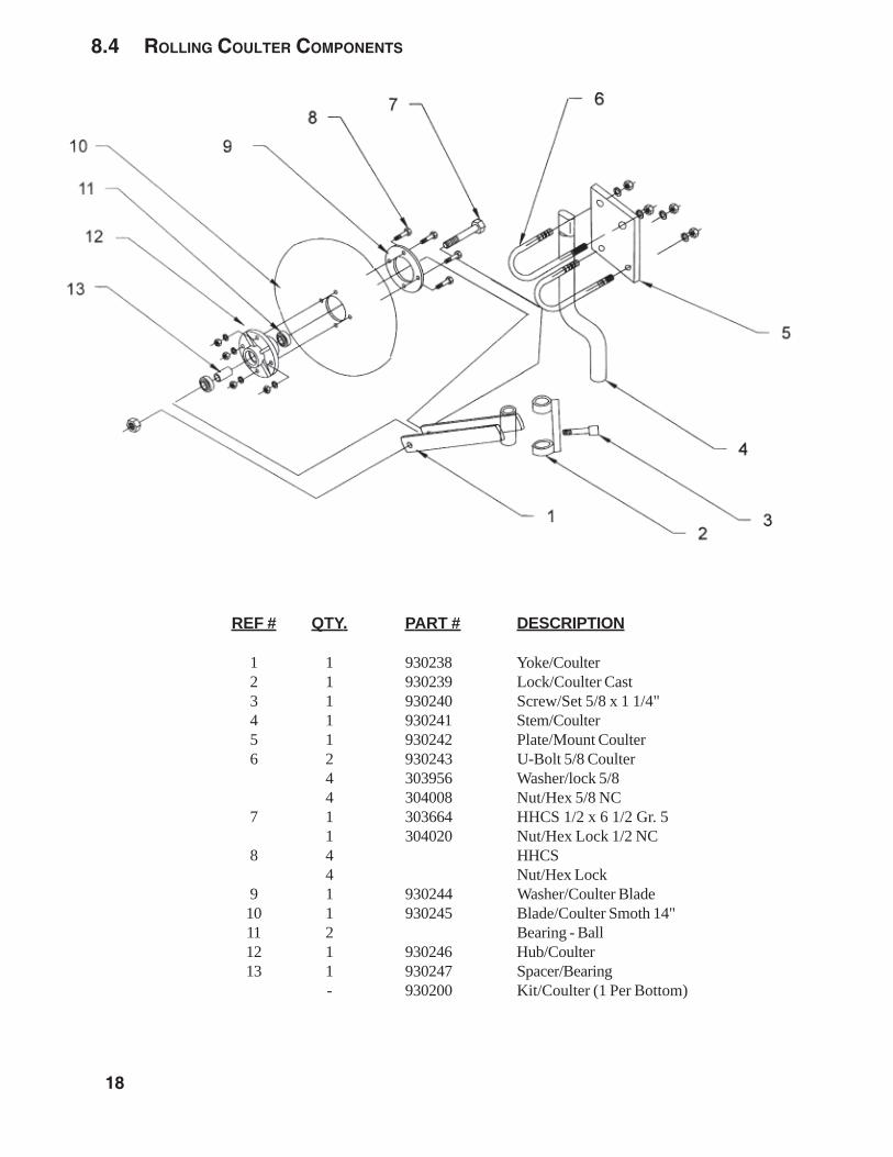
8.4 ROLLING COULTER COMPONENTS
REF # QTY. PART # DESCRIPTION
1 1 930238 Yoke/Coulter2 1 930239 Lock/Coulter Cast3 1 930240 Screw/Set 5/8 x 1 1/4"4 1 930241 Stem/Coulter5 1 930242 Plate/Mount Coulter6 2 930243 U-Bolt 5/8 Coulter
4 303956 Washer/lock 5/84 304008 Nut/Hex 5/8 NC
7 1 303664 HHCS 1/2 x 6 1/2 Gr. 51 304020 Nut/Hex Lock 1/2 NC
8 4 HHCS4 Nut/Hex Lock
9 1 930244 Washer/Coulter Blade10 1 930245 Blade/Coulter Smoth 14"11 2 Bearing - Ball12 1 930246 Hub/Coulter13 1 930247 Spacer/Bearing
- 930200 Kit/Coulter (1 Per Bottom)

19
GEARMORE, INC., warrants each new Gearmore product to be free from defects in material andworkmanship for a period of twelve (12) months from date of purchase to the original purchaser.This warranty shall not apply to implements or parts that have been subject to misuse, negligence,accident, or that have been altered in any way.
Our obligation shall be limited to repairing or replacement of any part, provided that such part isreturned within thirty (30) days from date of failure to Gearmore through the dealer from whom thepurchase was made, transportation charges prepaid.
This warranty shall not be interpreted to render us liable for injury or damages of any kind ornature, direct, consequential or contingent, to person or property. This warranty does not extendto loss of crops, loss because of delay in harvesting or any other expenses, for any other reasons.
Gearmore in no way warranties engines, tires, or other trade accessories, since these items arewarranted separately by these respective manufacturers.
Gearmore reserves the right to make improvements in design or changes in specification at anytime, without incurring any obligations to owners or units previously sold.
GEARMORE, INC.13477 Benson Ave.
Chino, CA 91710Always refer to and heed machine operating warning decals on machine.
9 LIMITED WARRANTY
The serial number of this product is stored in our computer database, thussubmitting a warranty registration card is not required.