mold standards 201106284 - fischer automotive systems
TRANSCRIPT

421� Page 1 6/28/11 Rev: 11/20/02
MOLD STANDARDS
Auburn Hills, Michigan, USA

� Page 2 XX-00-00-000-XX
REVISION RECORD
Original Release Date 10/17/99
Revised Release Date 08/19/02 Revised Release Date 11/20/02 Revised Release Date 09/05/03 Revised Release Date 02/19/04 Revised Release Date 02/25/04 Revised Release Date 02/08/06 Revised Release Date 08/23/06 Revised Release Date 06/14/07 Revised Release Date 01/07/09 Revised Release Date 10/13/09 Revised Release Date 11/02/09 Revised Release Date 02/04/10 Revised Release Date 06/28/11

� Page 3 XX-00-00-000-XX
TABLE OF CONTENTS
Section Page
1 Fischer Automotive Systems requirements for all Molds 5-6
Purpose…………………………………………………. 5 Application……………………………………………... 5 General Vendor Relationship…………………………... 5-6
2 Mold Design Process 7-10 Preliminary Mold Design Format and Approval………. 7 Final Tool Drawing Format and Approval…………….. 8-10
3 Tooling Requirements 11
General………………………………………………… 10
4 Mold Specifications 12-40
Venting………………………………………………… 12 Welding………………………………………………… 13 Die Parting Line………………………………………... 14 Clamp Slots…………………………………………….. 15 Eyebolts………………………………………………… 16 Core and Cavity Requirements………………………… 17 Core Pins……………………………………………….. 18 Slide and Lifter Requirements…………………………. 19-20 Hydraulic Cylinders……………………………………. 21 Runner and Gate Requirements…………………….. 22-27 Ejection Requirements…………………………………. 28-29 Cooling System………………………………………… 30 Construction Tolerance………………………………… 31 Clamping Plate Sizes………………………………….. 32-40
5 Mold Approval 41
Functional………………………………………………. 41 Dimensional…………………………………………….. 41

� Page 4 XX-00-00-000-XX
6 Program Timing 42
Mold Start Date………………………………………… 42 Mold Completion Date………………………………… 42 Tool Progress Reports………………………………… 42 Mold Delivery…………………………………………… 42

� Page 5 XX-00-00-000-XX
1 PRODUCTION MOLD DESIGN STANDARDS
Introduction
1.1 Purpose
This manual contains the specifications that define the requirements, which control the methods for manufacturing plastic injection production molds for Fischer Automotive Systems. These procedures outline the communication path and responsibility from quotation to tool completion between the mold vendor and Fischer Automotive Systems.
1.2 Application
This document applies to all materials used and services performed by the mold vendor for:
- Design and build of all plastic injection production molds.
- The implementation of all engineering changes during or after completion of all plastic injection production molds.
- All revisions to plastic injection production molds requested by Fischer Automotive Systems.
- All plastic injection mold quotations requested by Fischer Automotive Systems.
1.3 General Vendor Relationship
All new molds will be contracted and build through Fischer Automotive Systems’ Auburn Hills, Michigan facility.
Fischer Automotive Systems will provide the mold vendor sufficient information for an accurate quotation of the required mold. In all cases vendors are first required to quote.

� Page 6 XX-00-00-000-XX
1.3 General Vendor Relationship (cont.)
Vendor’s input of previous experience or knowledge, which will improve mold quality, efficiency, or cost, is greatly encouraged. These recommendations should be detailed in reply to quotation.
A dimensional part print or CAD data will be supplied with every quotation or purchase order. Prototype parts or SLA samples will be provided when possible.
Fischer Automotive Systems will provide the plastic material and shrink factor. The mold vendor will be responsible for the resulting steel sizes within the mold construction tolerances.
The mold vendor must separately quote any engineering design changes which affect cost or timing and must be proceeded by an amended purchase order from fischer Automotive Systems.
All part drawings, CAD data, sample parts or other materials is proprietary to Fischer Automotive Systems and confidentiality is expected.

� Page 7 XX-00-00-000-XX
2 MOLD DESIGN PROCESS
2.1 Preliminary Mold Design Format and Approval
All plastic injection molds will be contracted by Fischer Automotive Systems for design and build. Any Subletting of the mold designs by the tool source will be at their responsibility.
Fischer Automotive Systems, prior to any steel being ordered or starting construction of the mold, must approve all mold designs. The mold design approval process is as follows:
A) One (1) set of preliminary tool drawings are required no later than 2 weeks or 10% of tool delivery after the tool source is awarded a program, prior to ordering steel. Fischer Automotive Systems will make disposition on the drawings within three working days. The designs should consist of the following items, but not limited to:
• Partial Core Plan View.
• Partial Cavity Plan View.
• Sufficient detail to comprehend all mechanical functions of the mold.
• A layout of all proposed cooling circuits.
• A detail of the gate location and runner design including a five times size view of the gate proposal.
• All ejector pin sizes and locations (only one cavity if other cavities are identical or symmetrical.
• All sprue bushing, leader pins, and return pin sizes and locations.
• All support pillar sizes and locations.
• Overall dimensions of the mold including shut height and ejector stroke.
• Show outline of attachments protruding beyond the outside of the mold on the Core and Cavity Plan Views, such as cylinders, supporting inlets, etc.
• Knock-out Pattern
Any design changes will be marked on one set of drawings and returned to the tool source for updates. These changes will either be incorporated and resubmitted or incorporated into the finals as agreed upon.

� Page 8 XX-00-00-000-XX
No authorization to purchase any steel or components will be given until after preliminary mold approval has been given by Fischer Automotive Systems. Any material purchased prior to approval is at the mold vendor’s own risk.

� Page 9 XX-00-00-000-XX
2.2 Final Tool Drawing Format and Approval
Fischer Automotive Systems drawing approval does not relieve the toolmaker of accountability for proper tool function. Final mold designs cannot vary from the Preliminary approval without prior Fischer Automotive Systems authorization.
A) 2D Drawing Data and 3D Math Data of the Tool are required no later than 2 weeks or 20% of tool delivery after preliminary drawings has been approved. These final drawings are to include the completion of all the preliminary information stated under Preliminary Tool Drawing Format and Approval Process, plus all pertinent information to fully understand all aspects of the tool. The Final Drawings must be reviewed and approved by Fischer Automotive Systems before any steel can be cut, in most cases.
B) The first sheet of all tool designs shall have a list of all stock and purchased items making up the complete tool.
1) All stock sizes must show the minimum size, length, width, height diameters, etc. and the type and number of the material used to make the item.
2) All purchased items such as hydraulic cylinders, ejector pins, bushings, etc. must list source and complete ordering number of the item.
C) Hot runner molds shall have a separate sheet showing a schematic of the hot runner construction, location of heaters, zone division and electrical diagram.
D) An 8 x 11 sheet stating the sequence of operation for all molds, which have air or hydraulic cylinders, or mechanical slides, which must be timed into the sequence of the molding machine, should be included with the design.
E) All areas of the mold which show small detail which cannot be shown or dimensioned clearly on a full scale view, shall be shown 4 times size.
Any design recommendation to create a better steel condition or improve processing is encouraged. A marked up print showing the concessions, should be forwarded to Fischer Automotive Systems for approval.
Any tool that does not comply with these standards will be returned to the tool source for corrections at their own expense.
Any deviation from print dimensions or tolerances must be reviewed and approved by Fischer Automotive Systems. If the tool is not dimensionally correct to the received data and what was agreed upon, the tool source will be responsible for making corrections at their own expense.

� Page 10 XX-00-00-000-XX
2.2 Final Tool Drawing Format and Approval (cont.)
All tools will require an outside identification tag placed on the top of the tool, which will be issued by the Fischer Automotive Systems Tooling Engineer.
All water lines must be properly marked with “In” and “Out”. (Example: 1-In and 1-Out, 2 In and 2 Out, etc.)
All Hot Manifolds and tips must be identified by a plate attached to the outside of the mold showing relation in tool (Cavity Numbers) and wattage (or Amperage)/Voltage rating.
All cams, ejector pins, sleeves, and other components must be numbered with respect to cavity number.
Approximate tool weight to be shown on all final tool drawings.
Final mold design must include necessary assembly and detail information for future mold repair and maintenance.
All part design revisions during or after mold build will require the mold drawings to be updated reflecting the new part configuration. The design cost must be included with the tool revision cost.
Any tool that does not comply with these standards will be returned to the tool source for corrections at their own expense.

� Page 11 XX-00-00-000-XX
3 TOOLING REQUIREMENTS 3.1 General
• All completed molds must cycle automatically without operator assistance. If the tool source does not deem this feasible, it must be brought to the attention of Fischer Automotive Systems for resolution.
• Welding is not allowed without written approval from Fischer Automotive Systems.
• All outside edges of the mold plates are to be chamfered.
• Parting line pry slots are to be provided on all four corners of the mold. All plates need slots to make for ease of disassembly.
• “A” side clamp plate must have tapped holes to assist in “flipping“ the mold.(Section 4.5)
• If the tooling program is cancelled, a complete pricing breakdown showing material costs, labor hours, and rate must be supplied to Fischer Automotive Systems.
• In the case of Stop Orders, there must be a written notification from Fischer Automotive Systems to the tool source before any action can be taken.
• Mold components are to be designed in such a manner so as to minimize disassembly for maintenance and repair purposes.
• When a mold has more than one of a similar item, such as slides, they are to be nonsymmetrical and numbered so as to prevent improper assembly.
• Mold inserts are to be keyed to prevent incorrect assembly in tools.
• 2 Separate Date Wheels required on each tool: DME Style - Month w/Arrow and Multi Year w/Arrow. Size and location to be supplied by Fischer Automotive Systems.
• Cycle Counters are to be located on the top of each mold and recessed into a pocket, use Progress 100 Series, CVPL-100. Kai to supply new part number.
• Mold Number to be engraved on back of part.
• Mold Number to be stenciled on top of Mold in Yellow.
� Page 12 XX-00-00-000-XX
4 Mold Specifications
4.1 Venting
• Balanced runner vents to be same width as runner diameter, the depth will be specified depending on material of parts produced. Runner vents can be on either cavity or core side of mold.
• Vent pockets on the die parting line may be required when gasses are prevented from escaping due to location of runners and other cavities. Fischer Automotive Systems needs to be consulted if such a case arises.
• Venting to be shown on the final tool drawings and incorporated prior to 1st shots. Additional venting may be necessary after 1st shot review.
• Consideration should be taken when designing and building a tool to allow for enough room between cavities and runner for adding venting.
• The size and type of venting will be determined by the part design and the type of plastic material used for that particular application.
• All deep ribs to be vented with the use of vent pins or blades and attached to ejector system so the devices are self - cleaning.
• Vents are to be added every 25.0mm around the periphery of the part.

� Page 13 XX-00-00-000-XX
Mold Specifications (Cont.)
4.2 Welding
• All areas, which require welding in order to correct errors or in the normal course of mold building, are to be logged as to the exact areas welded. This log is to be maintained by the tool source until dimensional approval has been given. A copy of the log shall be shipped with the completed mold to Fischer Automotive Systems or prior to sending the mold out for texturing.
• Areas to be textured that have been welded must have the texture surface clearly marked.
• Improper grain appearance will not be deemed acceptable on the basis that the mold steel was welded and not properly conditioned.
• Engineering changes which result in the welding of the mold prior to its completion will be viewed from the same standpoint and also deem unacceptable.
• Engineering changes which result in the welding of the mold after die completion and texturing shall be discussed on an individual case basis by the tool source and Fischer Automotive Systems prior to incorporating the change.
• When welding, the use of compatible welding materials and processes to the tool steel hardness are required.

� Page 14 XX-00-00-000-XX
Mold Specifications (Cont.)
4.3 Die Parting Line
• Parting line shutoff area is to have 100% contact (except at vents), for a minimum of 1” around the entire cavity, at each corner of the mold immediately surrounding the guide pins and at all die locks. All other areas to be relieved by .030”.
• When a vertical shutoff condition is required, it shall be at a minimum of 7 degrees. Where this is not possible, the tool source is to contact the Fischer Automotive Systems Tooling Engineer for consideration.

� Page 15 XX-00-00-000-XX
Mold Specifications (Cont.)
4.4 Clamp Slots
• All clamp slots must be large and deep enough to hold the mold base securely to the platens when clamped into position.
• Clamp slots to be cleared completely out of each side on build-up base.
• Clamp slots to be located on the Operator and Non Operator side of the tool.
• Avoid running water lines into clamp slot area whenever possible.
• Size and location will be reviewed and approved by Fischer Automotive Systems.
• If an insulating sheet is required on a tool, subtract the thickness of the insulator sheet from the core and cavity side of the tool.
• Clamping plate thickness to be 7/8” unless directed otherwise by Fischer Automotive Systems.

� Page 16 XX-00-00-000-XX
Mold Specifications (Cont.)
4.5 Eyebolts
• All molds shall have sufficient eyebolt holes on all four sides and both halves including ejector box and any extra plates.
• Eyebolt hole sizes must be large and deep enough to hold while installing or removing the mold safely. For the length of the eyebolt, use two (2) times the diameter drilled and tapped.
o Example: For 5/8" – 11, drill and tap 1.25" deep.
• Molds to 999 lbs., are to have maximum 5/8" – 11eyebolt.
• Molds 1,000 to 2,999 lbs., are to have minimum 3/4" – 10 eyebolts.
• Molds 3,000 to 4,999 lbs., are to have 1” – 8 eyebolts.
• Eyebolts should be chamfered, to insure that the threads are completely into the mold.
• All eyebolts sizes and locations must be reviewed by Fischer Automotive Systems.
• Eyebolts on large tools should be close together so sling chains can be used without bending or putting stress on eyebolts.
• Eyebolts shall be located so that the molds, or mold halves, hang straight.
• 1 Eyebolt must be supplied with each tool coming into Fischer Automotive Systems.
• Eyebolt holes required on Cavity Clamping plate in each corner to assist in flipping tools and setting on it’s back.
• Eyebolt holes required on Core Clamping plate in each corner to assist in flipping tools and setting on it’s back.

� Page 17 XX-00-00-000-XX
Mold Specifications (Cont.)
4.6 Core and Cavity Requirements
• All Cavity, Core Blocks and Inserts are to be identified with material type and hardness.
• All cavities are to be labeled with sequential numbers. All core pins, ejection, and inserts are to be identified per cavity.
• All inserts must be retained in Cavity Block to prevent movement under injection pressure.
• Inserts that can be accidentally installed backwards must have a locating feature to assure proper orientation at assembly.
• A fine EDM finish is permissible unless otherwise specified. Deep ribbed areas must be draw polished.
• Draft angles are to be within dimensional tolerances. Vendor may request additional relief in areas believed to present ejection problems.
• 3.99” Locating Ring required on all tools. Max depth to be 2” unless directed otherwise by Fischer Automotive Systems.
• 5/32” Sprue Orifice required on tools 60 ton and below.
• 7/32” Sprue Orifice required on tools above 60 ton.
• All plates, inserts, blocks and large tool components should have tapped eyebolt holes for ease of handling.
• The use of die locks required on all 4 sides of the mold.

� Page 18 XX-00-00-000-XX
Mold Specifications (Cont.)
4.7 Core Pins
• All slides and/or lifters are to be identified with material type and hardness.
• All cores which are used to form holes up to ¼” are to be inserted. Sizes over ¼” will be determined by Fischer Automotive Systems when to insert.
• Core pins shall be held in place by the head of the pin.
• Core pins must be mounted so as to provide access for replacement without major disassembly of the mold. If this is not feasible, Fischer Automotive Systems must be consulted prior to tool construction.
• Standard PCS, D-M-E, or equivalent core pins of standard hardness are acceptable.
• Use numbers for identifying ejector pins and letters for identifying core pins.
• When radial orientation is critical, a positive lock at the head of the pin must be provided.
• All stationary core pins are to be held in place with two (2) set screws or retainer plate.
� Page 19 XX-00-00-000-XX
Mold Specifications (Cont.)
4.8 Slide and Lifter Requirements
• All slides and/or lifters are to be labeled with numbers that correspond to the cavity number.
• All slides and/or lifters are to be identified with material type and hardness.
• All lifters shall be fastened to the lifter bars by means of a steel pin.
• All angular lifters are to be fastened to the lifter bar or slide body with a self-locking screw, such as nylock or equivalent.
• Each component to the lifter assembly is to have the lifter number stamped on it.
• All actual lifter bar length is to be stamped on all lifter bars to aid in the manufacturing of replacement bars should breakage occur.
• Provisions for positive return by tapping the ejector plate must be provided for all tools with lifters.
• Mechanical slides are preferred over hydraulic slides.
• Shut-off angles on slides and lifters are to be five degrees minimum.
• Progressive Components style retainers are required in all slides.
• Horn pin and lifter rod angles cannot exceed 25 degrees. Heel block angles cannot exceed 30 degrees.
• Maintain a five-degree difference between horn pin and heel block angles.
• Slides that form large areas of part configuration must have cooling lines.
• All slides requiring hydraulic cylinders must have proximity switches.
• All sliding components of the lifter assembly shall have hardened steel to bronze contact and have provision for lubrication.
• Slides that open to the outside of the mold must have stops to prevent accidental dropout from the mold.

� Page 20 XX-00-00-000-XX
4.8 Slide and Lifter Requirements (cont)
• Cam pin to be long enough so that when actuated, will open slide for enough to clear part.
• All top of mold slides must have a spring to hold slide into position while tool is open. If springs are not possible to be installed, clothes pins are acceptable.
• When using detents for Slides, springs preferred 1st, detent plungers 2nd. Both styles must be removable from the front for ease of disassembly.

� Page 21 XX-00-00-000-XX
Mold Specifications (Cont.)
4.9 Hydraulic Cylinders
• All tools that have hydraulic cylinders mounted on the bottom of the mold must have support legs (4) long enough to clear the cylinders when setting on the floor.
• All cylinders and support legs must be shown on the preliminary and final tool drawings.
• All hydraulic core pulls must be flush or recessed back to 2.0mm maximum clearance at full stroke in open position.
• All core pulls and hydraulic cylinders are to be fully plumbed with one in and one out. Use hydraulic grade tubing for plumbing or flexible tubing.
• Mount cylinders to maximize ease of replacement and access without difficulty.
• All cylinders, fittings, hoses, etc… shall be selected to withstand a minimum of 3,000 psi continuous service.
• If cylinders are to be mounted to cams, do not use threaded rods on cams, use a T-slot style whenever possible or equivalent for mounting. These must also be shown on final tool drawings for our review and approval.
• Hydraulic fittings to be Parker 60 series. H3-62 female (set), H3-63 male (pull)
• Use switches to ensure positive set and pull.
Core 1: Power Pin #2, Pull Signal Pin #9, and Set Signal Pin #10
Core 2: Power Pin #2, Pull Signal Pin #11, and Set Signal Pin #12
Ejector Retract Verify: Power Pin #5 and Signal Pin #6
NOTE: All limit switches must be grounded to the ground terminal on the end of all connectors. All switches are to be N/O Limit Switches, Reed Switches or Proximity Switches.

� Page 22 XX-00-00-000-XX
Mold Specifications (Cont.)
4.10 Runner and Gate Requirements
• Location, type, and size of the gate will be determined by Fischer Automotive Systems at preliminary design stage.
• Runners are to be full round.
• Balanced runner systems are required.
• All gates must be detailed on final tool designs. View of gate must be shown and dimensioned 4 times size whenever possible.
• Ejector pins must be a minimum of 5/8 inch from sub-gates to prevent shearing of the gate.
• Hot Manifolds if required must be approved through Fischer Automotive Systems.
• All manifold connections must be on top of mold using the following:
Power = Harting p/n 09200162612, 16 pin male, 1-8 zones
Power = Harting p/n 09200162612, 24 pin male, 8-12 zones
Thermocouple = Harting p/n 09330102601, 10 pin male, 5 or less zones
Thermocouple = Harting p/n 09330102601, 24 pin male 6 - 8 zones
Thermocouple = Harting p/n 09330242701, 24 pin female, 9 - 12 zones
Housing Box Mount = p/n 09200160301
Housing Surface Mount = p/n 09200160251
• All heater zones must be rated for 220-240 volt operations.
• All wires from heaters must be placed in a fully enclosed channel, accessible from the outside of the mold and covered with a metal plate.

� Page 23 XX-00-00-000-XX
• All electrical systems are to be hooked up and tested before the tool is shipped.
• Manifold electrical schematics must be supplied with all final tool drawings.
• When the tool design requires a Hot Sprue/Manifold, use INCOE DTX/DTB Topless Gate Insert with a Topless End Cap 3 hole spreader STT/HTT/CTT depending on the material we will be molding…INCOE will recommend which tip to use.
• When constructing Molds that require a Hot Tip/Manifold for our Arburg Molding Machines 143T, 110T, 66T, 28T we require the following Plug:
o 3 Zone limit with Power/T.C. Combo
o Harting – Series Han E
o Power/TC = p/n 09330162601 – 16 pin male plug
o Housing Box Mount = p/n 09300160307 ref. McNaughton-McKay
o Housing Surface Mount = p/n 09300161250
• When the tool design requires a Hot Sprue/Manifold, a service pack is required to accompany the tool at delivery to Fischer which should consist of spare heater band, thermocouple for each heater and tip insert. Contact Incoe for cost information.

� Page 24 XX-00-00-000-XX
4.10 Runner and Gate Requirements (Cont.)
• Tool sources are to furnish one extra nozzle drop and manifold heater with every hot manifold job.
• All preliminary tool drawings must state the type of hot runner system used and nozzle drop locations.
• Manifold schematic must be placed on the outside of the tool on Non-Operator side.
• Insulator plates need to be attached to Cavity Side when Hot Runner is being utilized. (Note: Check depth of locating ring, may have to extend)
• Reverse taper sprue puller required.
• Sprue puller diameter to be equal to or greater than sprue at runner intersection.
• Sprue puller depth to be to at least twice the diameter of the runner diameter.

� Page 25 XX-00-00-000-XX
> 1
Hot Runner Connections
06/27/11
Hot Runner Power Plug/Thermocouple with 8 or Less Zones
Power Plug = P/N 09200162612 – 16 Pin Male
Thermocouple Plug = P/N 09330102601 - 10 Pin Male (5 or less Zones)
Thermocouple Plug = P/N 09330242601 - 24 Pin Male (6-8 Zones)
Housing Box Mount – P/N 09200160301
Housing Surface Mount – P/N 09200160251
Power Plug Schematic
Zone 1 – pin 1 & 9
Zone 2 – pin 2 & 10
Zone 3 – pin 3 & 11
Zone 4 – pin 4 & 12
Zone 5 – pin 5 & 13
Zone 6 – pin 6 & 14
Zone 7 – pin 7 & 15
Zone 8 – pin 8 & 16
Thermocouple Plug with 5 or Less
Zone Schematic
Zone 1 - + white pin 1
- red pin 6
Zone 2 - + white pin 2
- red pin 7
Zone 3 - + white pin 3
- red pin 8
Zone 4 - + white pin 4
- red pin 9
Zone 5 - + white pin 5
- red pin 10
Thermocouple Plug with
6 - 8 Zone Schematic
Zone 1 - + white pin 1
- red pin 13
Zone 2 - + white pin 2
- red pin 14
Zone 3 - + white pin 3
- red pin 15
Zone 4 - + white pin 4
- red pin 16
Zone 5 - + white pin 5
- red pin 17
Zone 6 - + white pin 6
- red pin 18
Zone 7 - + white pin 7
- red pin 19
Zone 8 - + white pin 8
- red pin 20

� Page 26 XX-00-00-000-XX
> 2
Hot Runner Connections
06/27/11
Hot Runner Power Plug/Thermocouple with more than 8 Zones
Power Plug = P/N 092330242601 – 24 Pin Male
Thermocouple Plug = P/N 09330242701 - 24 Pin Female
Housing Box Mount – P/N 09200160301
Housing Surface Mount – P/N 09200160251
Power Plug Schematic
Zone 1 – pin 1 & 13
Zone 2 – pin 2 & 14
Zone 3 – pin 3 & 15
Zone 4 – pin 4 & 16
Zone 5 – pin 5 & 17
Zone 6 – pin 6 & 18
Zone 7 – pin 7 & 19
Zone 8 – pin 8 & 20
Zone 9 – pin 9 & 21
Zone 10 – pin 10 & 22
Zone 11 – pin 11 & 23
Zone 12 – pin 12 & 24
Thermocouple Plug with
9 -1 2 Zone Schematic
Zone 1 - + white pin 1 / - red pin 13
Zone 2 - + white pin 2 / - red pin 14
Zone 3 - + white pin 3 / - red pin 15
Zone 4 - + white pin 4 / - red pin 16
Zone 5 - + white pin 5 / - red pin 17
Zone 6 - + white pin 6 / - red pin 18
Zone 7 - + white pin 7 / - red pin 19
Zone 8 - + white pin 8 / - red pin 20
Zone 9 - + white pin 9 / - red pin 21
Zone 10 - + white pin 10 /- red pin 22
Zone 11 - + white pin 11 /- red pin 23
Zone 12 - + white pin 12 /- red pin 24
� Page 27 XX-00-00-000-XX
> 3
Hot Runner Connections
06/27/11
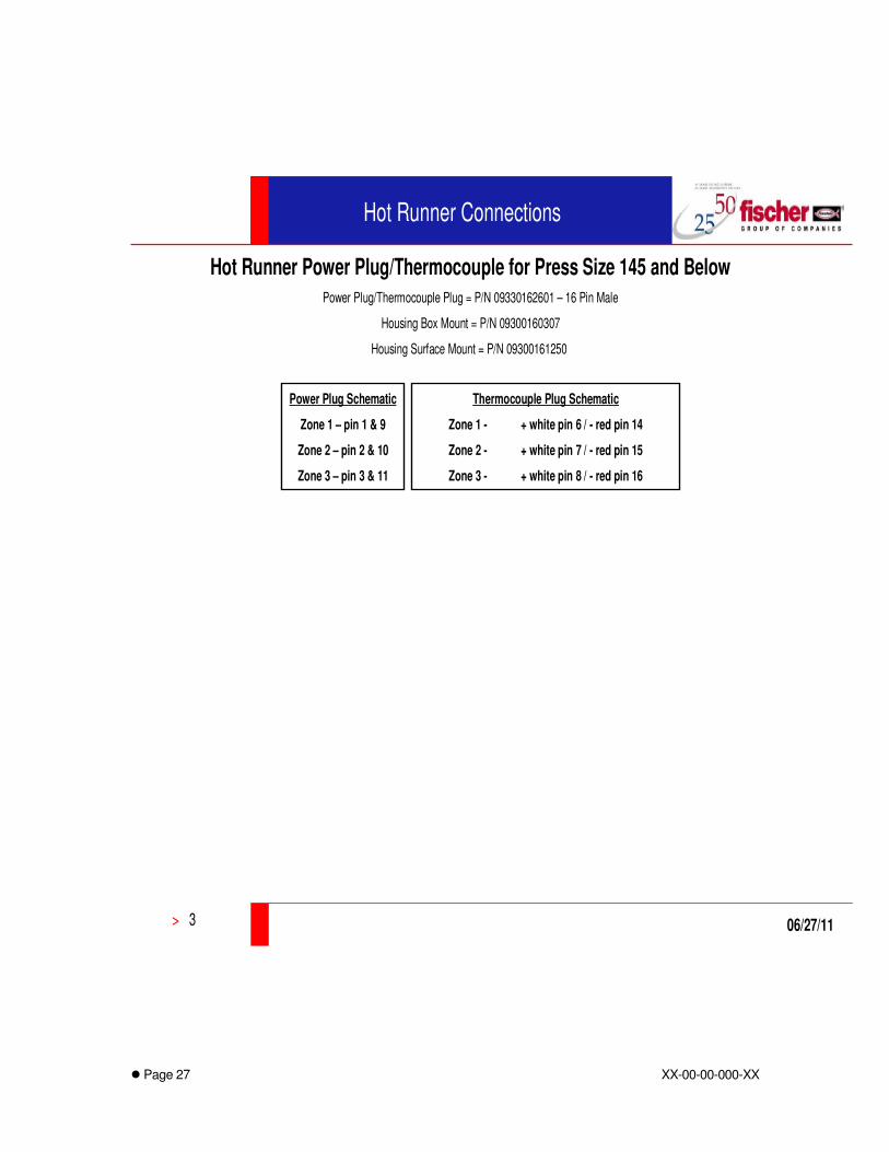
Hot Runner Power Plug/Thermocouple for Press Size 145 and Below
Power Plug/Thermocouple Plug = P/N 09330162601 – 16 Pin Male
Housing Box Mount = P/N 09300160307
Housing Surface Mount = P/N 09300161250
Power Plug Schematic
Zone 1 – pin 1 & 9
Zone 2 – pin 2 & 10
Zone 3 – pin 3 & 11
Thermocouple Plug Schematic
Zone 1 - + white pin 6 / - red pin 14
Zone 2 - + white pin 7 / - red pin 15
Zone 3 - + white pin 8 / - red pin 16

� Page 28 XX-00-00-000-XX
Mold Specifications (Cont.)
4.11 Ejection Requirements
• Knockout patterns will be supplied at time of preliminary mold design.
• Knockout tap to be ½” – 13.
• All mold units must have guided ejection in four places.
• If return springs are required, it will be determined at initial preliminary drawing review.
• For molds requiring a positive return system, a limit switch as a sensor for position verification is required. Use DME Thinswitch Limit Switch, TSW2220 with Harting 09200162612 16 pin Male Plug.
• Ejector location and travel must adequately remove part from mold including short shots.
• A stripper plate is required on parts without enough ejection surfaces or is subject to distortion.
• All ejector pins, blades, and sleeves are to be hardened with annealed heads.
• All ejector pins are to be PCS, D-M-E Hotwork pins or their equivalent.
• All ejector pin clearance holes in support plate and ejector retainer plate are to have 1/32” clearance. Reamed holes for ejector pins should have no more than 1 inch of bearing to insure proper die life.
• Ejector Pins and Sleeves where radial orientation is critical, a positive lock (Key) at the head must be provided.
• All ejector pin applications must be reviewed and approve by Fischer Automotive Systems.
• Stamp identification on ejector pins and their locations in the tool for taking the mold apart and ease of assembling it back together. All components must be numbered or lettered.
• When Sleeve ejection is required, use standard D-M-E or equivalent for ejector pin and ejector sleeve.

� Page 29 XX-00-00-000-XX
4.11 Ejection Requirements (Cont.)
• Double ejection materials to be the same material as standard ejection systems.
• Double ejection must be reviewed and approved at the preliminary design stage by Fischer Automotive Systems.
• Double ejection requires the use of four return pins using standard D-M-E return pins or equivalent, with springs.
• Ejector Box Covers are required if opening is on top of the mold, use clear Plexiglas and mount with screws.
• Ejector Spacers (Pucks) to be installed flush to back plate.

� Page 30 XX-00-00-000-XX
Mold Specifications (Cont.)
4.12 Cooling System
• All waterlines are to be 7/16” diameter with ¼-18 N.P.T. 300 series. D-M-E style JP-352 or equivalent.
• All water fittings to be 1/8 inch below surface of the mold per D-M-E standards.
• No waterlines closer than 3/16” to any cavity feature, bolt holes, ejector pin, etc., to prevent cracking.
• All fittings must be taped prior to installation.
• No water fittings are allowed in clamp slots.
• Water fittings should be on non-operator side of mold.
• Numerous water circuits may require water manifolds for quicker set-ups.
• All cooling lines are to be pressure tested prior to shipment by mold vendor.
• All cooling lines are to be stamped with circuit number and “IN” or “OUT”. (Example: 1-In, 1-Out, 2-In, 2-Out, 3-In, 3-Out, etc.)
• Straight-drilled lines are preferred to baffles.
• Water lines to be directly incorporated into all cams, lifters, and inserts, unless otherwise directed by Fischer Automotive Systems.
• All pipe joints and plugs are to be sealed with an appropriate thread sealant such a Teflon tape, non-hardening permatex, etc.
• All water systems must be shown on preliminary and final tool drawings.
• If jumpers are required on the bottom of the tool, legs must be added to the tool and jumpers plumbed.

� Page 31 XX-00-00-000-XX
Mold Specifications (Cont.)
4.13 Construction Tolerance
• Mold steel sizes are to be adjusted to apply material shrinkage supplied by Fischer Automotive Systems.
• Any warpage compensation will be supplied by Fischer Automotive Systems.
• Steel sizes must be within 40 percent of the part print tolerance.

� Page 32 XX-00-00-000-XX
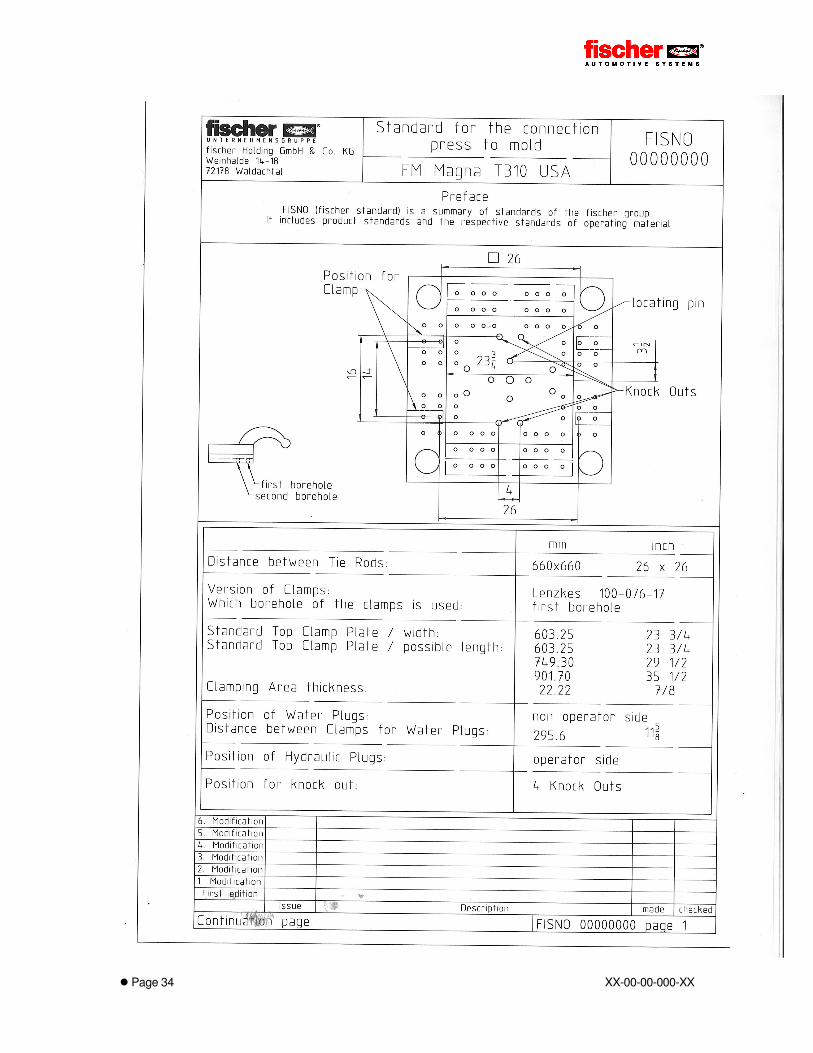
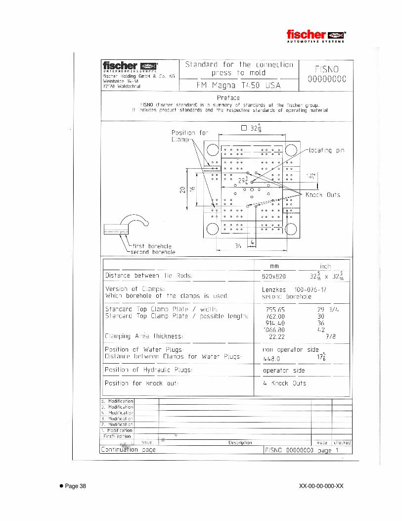
4.14 Clamping Plate Sizes

� Page 33 XX-00-00-000-XX
� Page 34 XX-00-00-000-XX

� Page 35 XX-00-00-000-XX

� Page 36 XX-00-00-000-XX

� Page 37 XX-00-00-000-XX
� Page 38 XX-00-00-000-XX

� Page 39 XX-00-00-000-XX

� Page 40 XX-00-00-000-XX
� Page 41 XX-00-00-000-XX
5 MOLD APPROVALS
5.1 Functional
The mold vendor is contracted to manufacture a mold that is fully functional as intended. All costs incurred are the mold vendor’s responsibility.
The mold vendor must verify the function of the tool with tryouts at their cost prior to shipment to Fischer Automotive Systems. A successful tryout must include the following:
• Tool must have shut-offs with no flash.
• Tool must be mechanically operational of all components including part ejection.
• Parts must be free of defects.
• Tool must have proper venting with no burning or gassing.
• Tool must have balanced runners and balanced cavity fill.
• Part parting lines must be clean with no visible flash.
After the mold vendor has satisfied Fischer Automotive Systems, it will be sampled at Fischer Automotive Systems for verification.
5.2 Dimensional
The mold vendor may be asked to verify steel sizes in areas of non-compliance.
The mold vendor will be responsible to repair any discrepant steel sizes. Fischer Automotive Systems will not assume any costs associated for this repair.
Fischer Automotive Systems will assume costs to repair any discrepant areas caused by improper or non-uniform material shrinkage.

� Page 42 XX-00-00-000-XX
6 PROGRAM TIMING
6.1 Mold Start Date
Mold build begins the date the vendor receives a Fischer Automotive Systems Mold Build Authorization Form and/or purchase order and approved CAD data or a part print.
In some instances, Fischer Automotive Systems may issue verbal authorization or a written quotation confirmation to proceed. A purchase order will follow within two weeks after such an authorization is given.
6.2 Mold Completion Date
The delivery date is stated on the Mold Build Authorization and/or purchase order. This is the agreed upon date the mold is fully operational, grained, and ready for continuous production intent. Please quote lead times accordingly.
The mold vendor must adhere to all delivery commitments. If circumstances arise jeopardizing delivery, immediate notification is required. This may include any delays caused by Fischer Automotive Systems.
6.3 Tool Progress reports
Mold vendors must submit weekly progress reports on all production molds. These reports should be in Microsoft Project format. The reports must include the following:
- All sequences related to mold delivery.
- Percentage of completion of manufacturing sequences.
- Any change in sequences or delivery.
Any changes must be authorized by Fischer Automotive Systems.
Fischer Automotive Systems reserves the right to visit the mold vendor to ensure timely delivery and adherence to the mold standard.
6.4 Mold Delivery
The mold vendor is responsible for all transportation cost incurred to obtain full mold approval.