modules 1-3
DESCRIPTION
Module 3 added pgs 29-42TRANSCRIPT
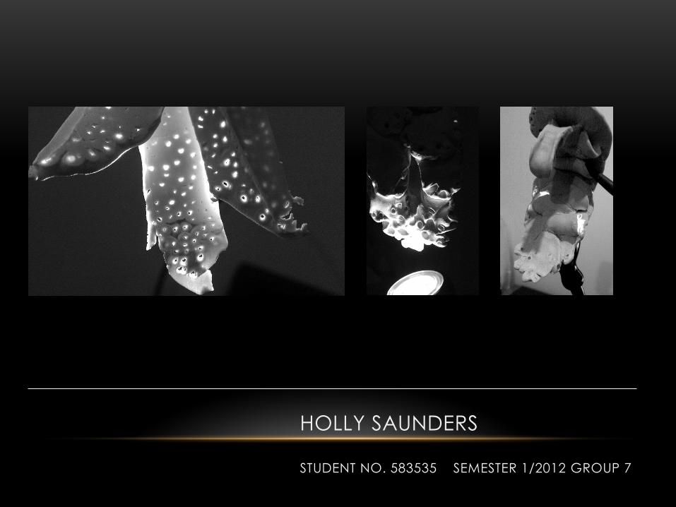
HOLLY SAUNDERS
STUDENT NO. 583535 SEMESTER 1/2012 GROUP 7
MODULE 1 - PETRIFIED WOOD
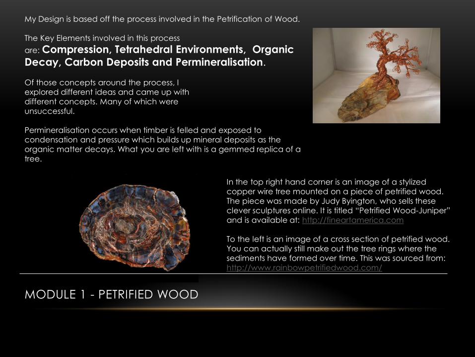
My Design is based off the process involved in the Petrification of Wood.
The Key Elements involved in this process
are: Compression, Tetrahedral Environments, Organic
Decay, Carbon Deposits and Permineralisation.
Of those concepts around the process, I
explored different ideas and came up with
different concepts. Many of which were
unsuccessful.
Permineralisation occurs when timber is felled and exposed to
condensation and pressure which builds up mineral deposits as the
organic matter decays. What you are left with is a gemmed replica of a
tree.
In the top right hand corner is an image of a stylized
copper wire tree mounted on a piece of petrified wood.
The piece was made by Judy Byington, who sells these
clever sculptures online. It is titled “Petrified Wood-Juniper”
and is available at: http://fineartamerica.com
To the left is an image of a cross section of petrified wood.
You can actually still make out the tree rings where the
sediments have formed over time. This was sourced from:
http://www.rainbowpetrifiedwood.com/

MODULE 1 - EXPLORING COMPRESSION
In exploring compression as a part of the petrification process I realised the concept was a very vast one to grasp. It was a bit of a challenge for me to narrow it down. Nevertheless, I did and
it was a precursor to my synergetic outcome.
Above is a quick sketch of a stylized arrow representing two forces moving
towards each other to create a sense of compression. Because they are
identical it is intended that they equal each other in force.
To the right you have circles and spirals complimented by the springs below.
I have experimented with circular
structures and cylinders to
strengthen tensile bonds.
I decided that I could elaborate
further on this concept and so I
developed further ideas to
communicate a more abstract
notion of compression, in order to
symbolise one of the major
processes petrified wood
undergoes.
MODULE 1 - EXPLORING COMPRESSION CONTINUED…
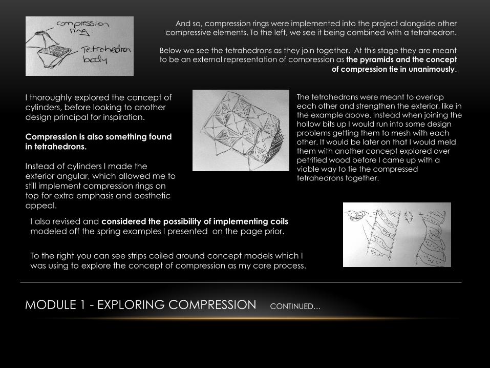
And so, compression rings were implemented into the project alongside other compressive elements. To the left, we see it being combined with a tetrahedron.
Below we see the tetrahedrons as they join together. At this stage they are meant to be an external representation of compression as the pyramids and the concept
of compression tie in unanimously.
The tetrahedrons were meant to overlap each other and strengthen the exterior, like in the example above. Instead when joining the hollow bits up I would run into some design problems getting them to mesh with each other. It would be later on that I would meld them with another concept explored over petrified wood before I came up with a
viable way to tie the compressed tetrahedrons together.
I thoroughly explored the concept of
cylinders, before looking to another
design principal for inspiration.
Compression is also something found
in tetrahedrons.
Instead of cylinders I made the
exterior angular, which allowed me to
still implement compression rings on
top for extra emphasis and aesthetic
appeal.
I also revised and considered the possibility of implementing coils
modeled off the spring examples I presented on the page prior.
To the right you can see strips coiled around concept models which I
was using to explore the concept of compression as my core process.
MODULE 1 - EXPLORING COMPRESSION CONTINUED…
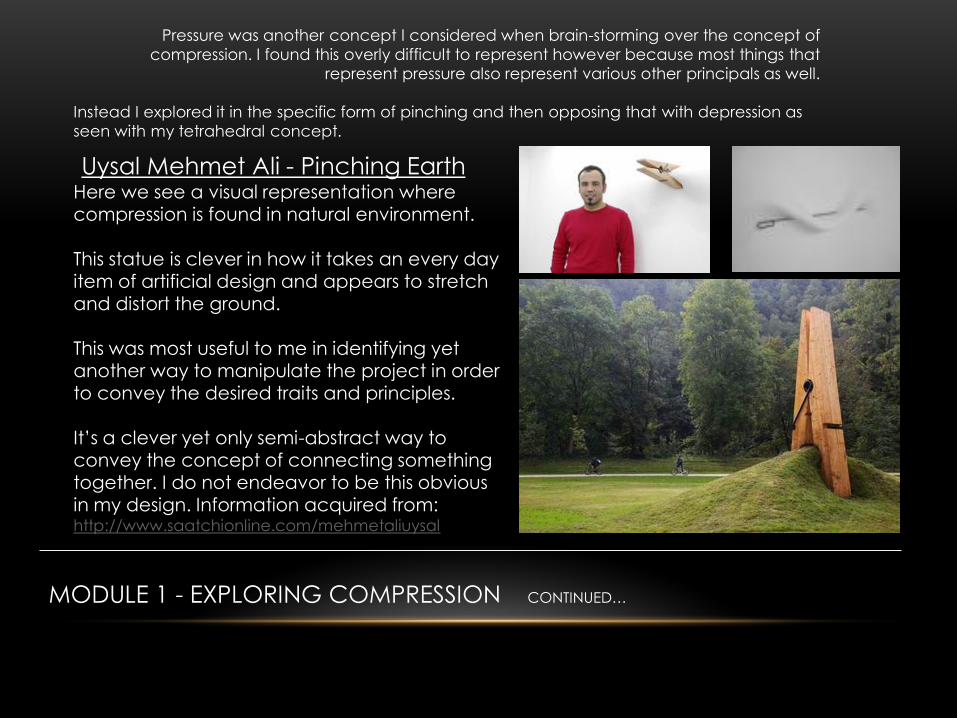
Pressure was another concept I considered when brain-storming over the concept of
compression. I found this overly difficult to represent however because most things that
represent pressure also represent various other principals as well.
Instead I explored it in the specific form of pinching and then opposing that with depression as
seen with my tetrahedral concept.
Uysal Mehmet Ali - Pinching Earth Here we see a visual representation where compression is found in natural environment.
This statue is clever in how it takes an every day item of artificial design and appears to stretch and distort the ground. This was most useful to me in identifying yet another way to manipulate the project in order
to convey the desired traits and principles. It’s a clever yet only semi-abstract way to convey the concept of connecting something together. I do not endeavor to be this obvious in my design. Information acquired from: http://www.saatchionline.com/mehmetaliuysal
MODULE 1 - EXPLORING COMPRESSION CONTINUED…
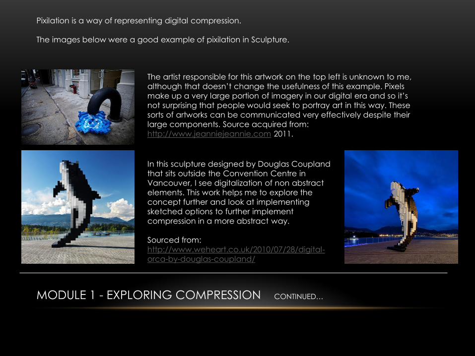
Pixilation is a way of representing digital compression.
The images below were a good example of pixilation in Sculpture.
The artist responsible for this artwork on the top left is unknown to me,
although that doesn’t change the usefulness of this example. Pixels
make up a very large portion of imagery in our digital era and so it’s
not surprising that people would seek to portray art in this way. These
sorts of artworks can be communicated very effectively despite their
large components. Source acquired from:
http://www.jeanniejeannie.com 2011.
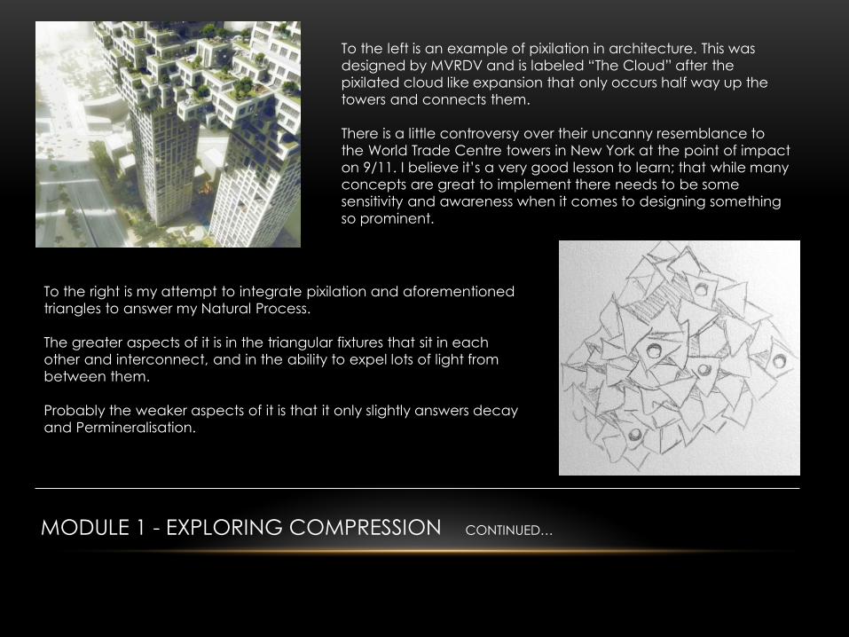
In this sculpture designed by Douglas Coupland
that sits outside the Convention Centre in
Vancouver, I see digitalization of non abstract
elements. This work helps me to explore the
concept further and look at implementing
sketched options to further implement
compression in a more abstract way.
Sourced from:
http://www.weheart.co.uk/2010/07/28/digital-
orca-by-douglas-coupland/
MODULE 1 - EXPLORING COMPRESSION CONTINUED…
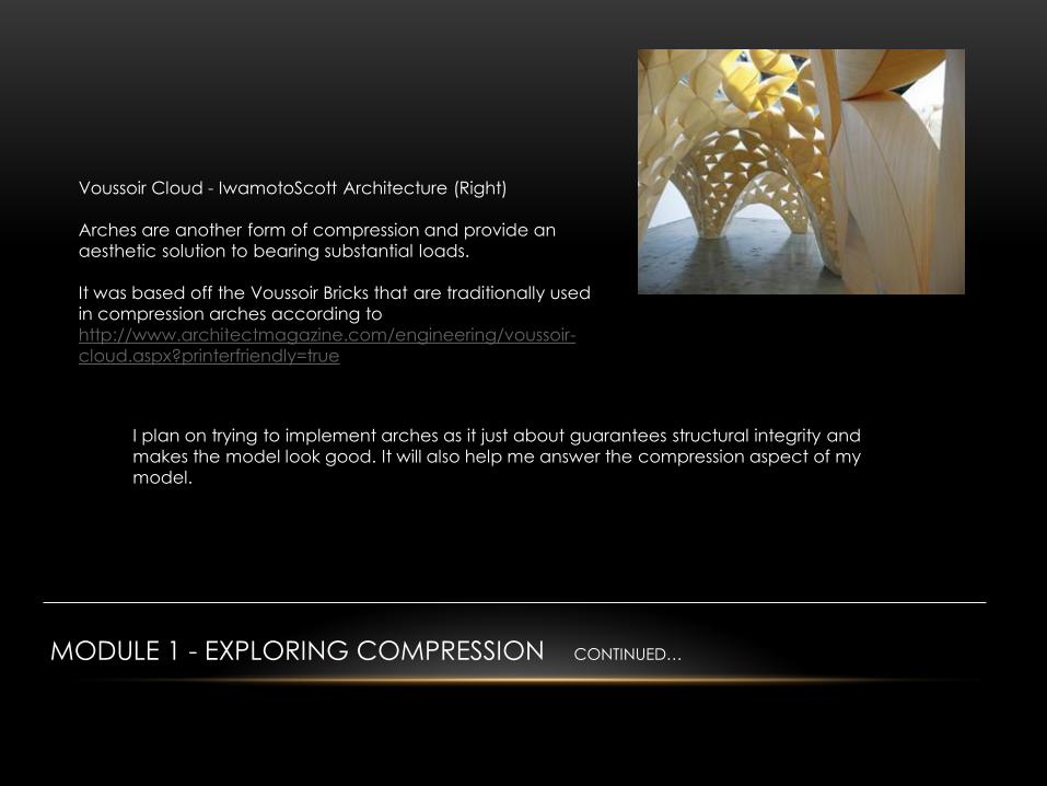
To the left is an example of pixilation in architecture. This was
designed by MVRDV and is labeled “The Cloud” after the
pixilated cloud like expansion that only occurs half way up the
towers and connects them.
There is a little controversy over their uncanny resemblance to
the World Trade Centre towers in New York at the point of impact
on 9/11. I believe it’s a very good lesson to learn; that while many
concepts are great to implement there needs to be some
sensitivity and awareness when it comes to designing something
so prominent.
To the right is my attempt to integrate pixilation and aforementioned
triangles to answer my Natural Process.
The greater aspects of it is in the triangular fixtures that sit in each
other and interconnect, and in the ability to expel lots of light from
between them.
Probably the weaker aspects of it is that it only slightly answers decay
and Permineralisation.
MODULE 1 - EXPLORING COMPRESSION CONTINUED…
Voussoir Cloud - IwamotoScott Architecture (Right)
Arches are another form of compression and provide an
aesthetic solution to bearing substantial loads.
It was based off the Voussoir Bricks that are traditionally used
in compression arches according to
http://www.architectmagazine.com/engineering/voussoir-
cloud.aspx?printerfriendly=true
I plan on trying to implement arches as it just about guarantees structural integrity and
makes the model look good. It will also help me answer the compression aspect of my
model.

MODULE 1 - EXPLORING TETRAHEDRONS
Tetrahedrons display compressive qualities and have great structural
integrity. They are as important to the process of petrifying wood as
much as compression is.
To the right is the City Council Building in Tempe, Arizona. It not only
adopts the inverted triangular exterior but also has a mass of windows
that let a lot of light in, which is something I will explore later.
Designed by architects Michael and Kemper Goodwin and
completed in 1970/1. Sourced at:
http://www.tempe.gov/historicpres/HE-HistoricEligible/CityHall.html
To the left is My own development on tetrahedrons. I have thought to
implement holes between tiles and create negative space to tie in with
my next concept: Permineralisation and decay. The tetrahedrons were
going to be overlaid on paneling before I decided it was too intricate and
didn’t answer the process properly.
In the bottom right hand corner I
have included another example of
Modern Architecture adopting Inverted Pyramids. This piece is the
Victoria & Albert Museum in Scotland which was conceptualised by
http://www.rex-ny.com/ This building also admits a lot of light and is
designed specifically as a creative hub.

MODULE 1 - EXPLORING DECAY & PERMINERALISATION
After covering the concepts of Compression and Tetrahedrons, I
moved to the concept of exploring the decay and Permineralisation
that happens to the wood after it falls.
I started to think about all the negative space that I would need to
have in order to make an effective lantern and realised that it ties in
really well with the concept of decay and the way that light reacts
when it hits minerals.
Therefore I opted to explore the different ways I could adapt holes in my work to demonstrate this concept.
In the top right corner is a model lantern by http://www.etruxes.com/architecture/tapered-circles/ which
more or less gives you an idea of how I wanted to incorporate the holes in my paneling. They developed
these holes using the picture below.
What resulted from my research into this
was a lot of experimentation with the way
light plays off models and refracts off gloss
and shiny things.
MODULE 1 - EXPLORING DECAY & PERMINERALISATION CONTINUED…
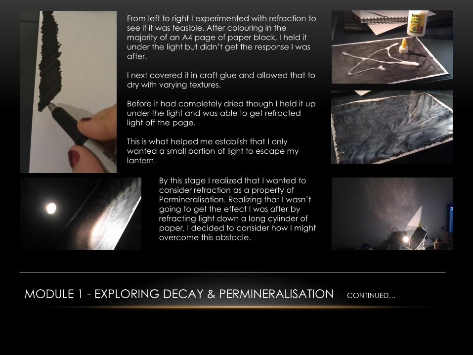
From left to right I experimented with refraction to
see if it was feasible. After colouring in the
majority of an A4 page of paper black, I held it
under the light but didn’t get the response I was
after.
I next covered it in craft glue and allowed that to
dry with varying textures.
Before it had completely dried though I held it up
under the light and was able to get refracted
light off the page.
This is what helped me establish that I only
wanted a small portion of light to escape my
lantern.
By this stage I realized that I wanted to
consider refraction as a property of
Permineralisation. Realizing that I wasn’t
going to get the effect I was after by
refracting light down a long cylinder of
paper, I decided to consider how I might
overcome this obstacle.
MODULE 1 - EXPLORING DECAY & PERMINERALISATION CONTINUED…
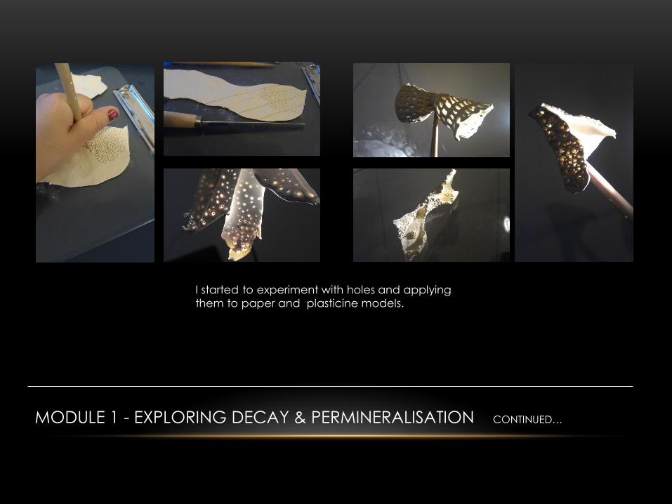
I started to experiment with holes and applying
them to paper and plasticine models.
MODULE 1 - EXPLORING DECAY & PERMINERALISATION CONTINUED…
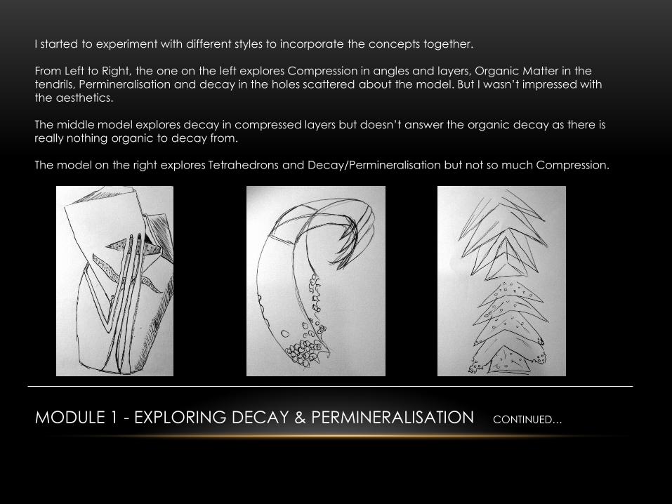
I started to experiment with different styles to incorporate the concepts together.
From Left to Right, the one on the left explores Compression in angles and layers, Organic Matter in the
tendrils, Permineralisation and decay in the holes scattered about the model. But I wasn’t impressed with
the aesthetics.
The middle model explores decay in compressed layers but doesn’t answer the organic decay as there is
really nothing organic to decay from.
The model on the right explores Tetrahedrons and Decay/Permineralisation but not so much Compression.
MODULE 1 - EXPLORING THE RADIOISOTOPE OF CARBON
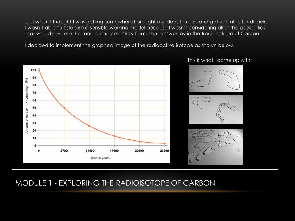
Just when I thought I was getting somewhere I brought my ideas to class and got valuable feedback.
I wasn’t able to establish a sensible working model because I wasn’t considering all of the possibilities
that would give me the most complementary form. That answer lay in the Radioisotope of Carbon.
I decided to implement the graphed image of the radioactive isotope as shown below.
This is what I came up with:
MODULE 1 - DEFINING THE ABSTRACTION OF PETRIFIED WOOD
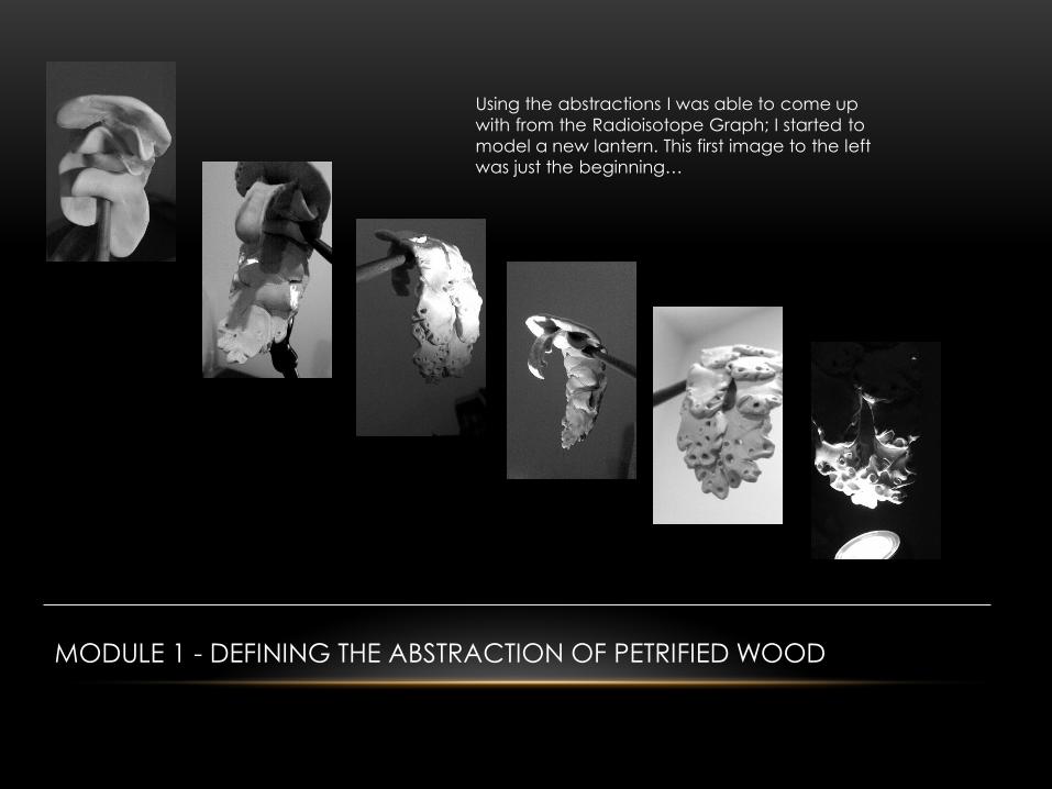
Using the abstractions I was able to come up
with from the Radioisotope Graph; I started to
model a new lantern. This first image to the left
was just the beginning…
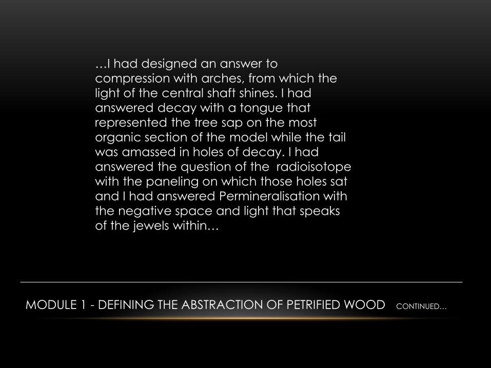
…I had designed an answer to
compression with arches, from which the
light of the central shaft shines. I had
answered decay with a tongue that
represented the tree sap on the most
organic section of the model while the tail
was amassed in holes of decay. I had
answered the question of the radioisotope
with the paneling on which those holes sat
and I had answered Permineralisation with
the negative space and light that speaks
of the jewels within…
MODULE 1 - DEFINING THE ABSTRACTION OF PETRIFIED WOOD CONTINUED…

Module 2
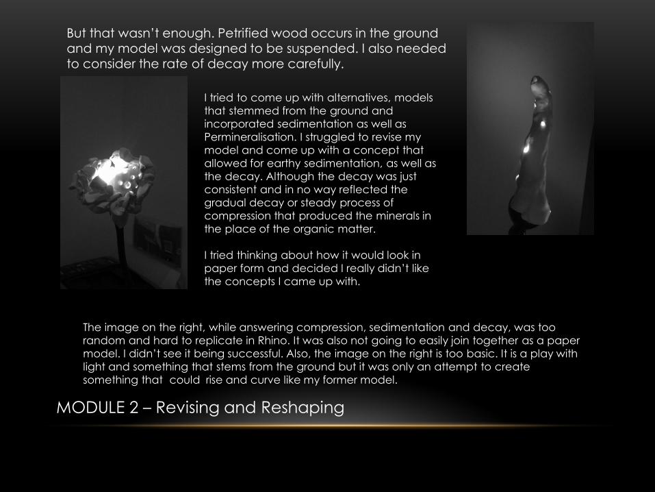
But that wasn’t enough. Petrified wood occurs in the ground and my model was designed to be suspended. I also needed
to consider the rate of decay more carefully.
I tried to come up with alternatives, models
that stemmed from the ground and
incorporated sedimentation as well as
Permineralisation. I struggled to revise my
model and come up with a concept that
allowed for earthy sedimentation, as well as
the decay. Although the decay was just
consistent and in no way reflected the
gradual decay or steady process of
compression that produced the minerals in
the place of the organic matter.
I tried thinking about how it would look in
paper form and decided I really didn’t like
the concepts I came up with.
The image on the right, while answering compression, sedimentation and decay, was too
random and hard to replicate in Rhino. It was also not going to easily join together as a paper
model. I didn’t see it being successful. Also, the image on the right is too basic. It is a play with
light and something that stems from the ground but it was only an attempt to create
something that could rise and curve like my former model.
MODULE 2 – Revising and Reshaping
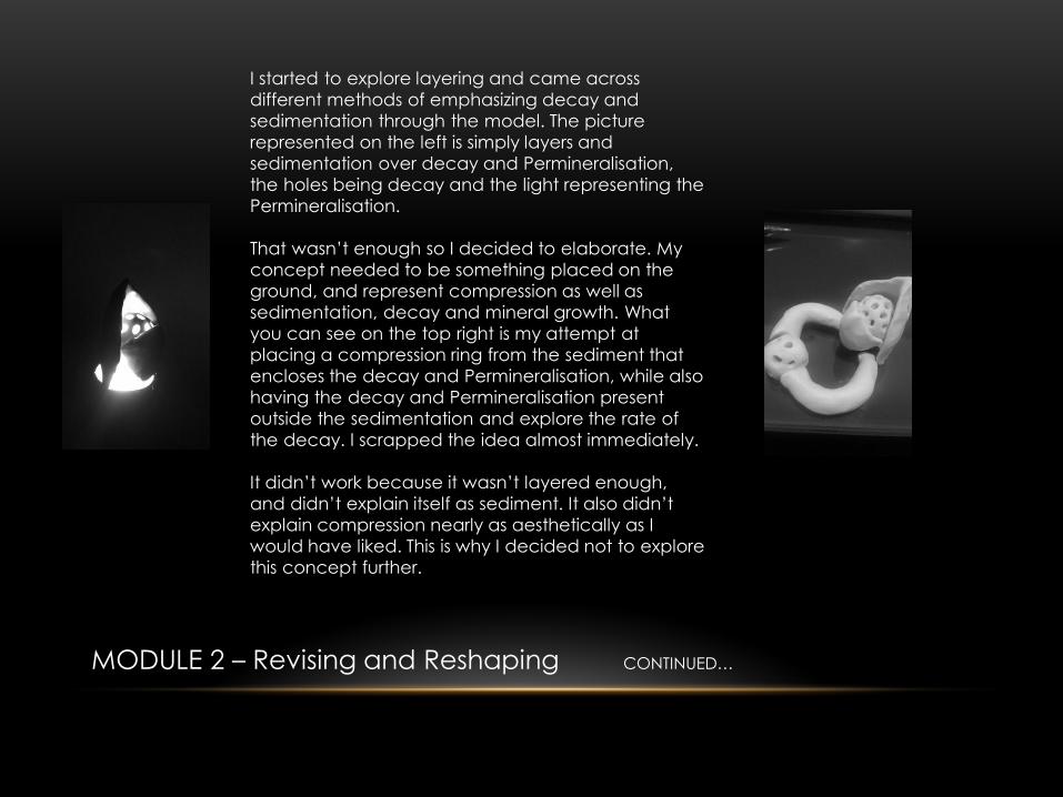
I started to explore layering and came across
different methods of emphasizing decay and
sedimentation through the model. The picture
represented on the left is simply layers and
sedimentation over decay and Permineralisation,
the holes being decay and the light representing the
Permineralisation.
That wasn’t enough so I decided to elaborate. My
concept needed to be something placed on the
ground, and represent compression as well as
sedimentation, decay and mineral growth. What
you can see on the top right is my attempt at
placing a compression ring from the sediment that
encloses the decay and Permineralisation, while also
having the decay and Permineralisation present
outside the sedimentation and explore the rate of
the decay. I scrapped the idea almost immediately.
It didn’t work because it wasn’t layered enough,
and didn’t explain itself as sediment. It also didn’t
explain compression nearly as aesthetically as I
would have liked. This is why I decided not to explore
this concept further.
MODULE 2 – Revising and Reshaping CONTINUED…
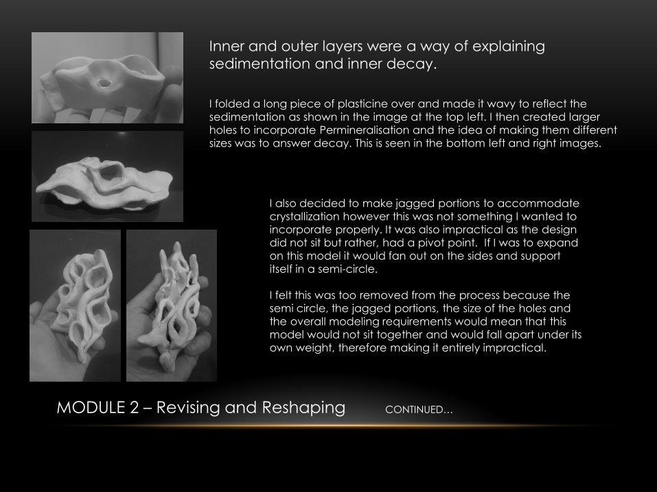
I folded a long piece of plasticine over and made it wavy to reflect the
sedimentation as shown in the image at the top left. I then created larger
holes to incorporate Permineralisation and the idea of making them different
sizes was to answer decay. This is seen in the bottom left and right images.
I also decided to make jagged portions to accommodate
crystallization however this was not something I wanted to
incorporate properly. It was also impractical as the design
did not sit but rather, had a pivot point. If I was to expand
on this model it would fan out on the sides and support
itself in a semi-circle.
I felt this was too removed from the process because the
semi circle, the jagged portions, the size of the holes and
the overall modeling requirements would mean that this
model would not sit together and would fall apart under its
own weight, therefore making it entirely impractical.
Inner and outer layers were a way of explaining
sedimentation and inner decay.
MODULE 2 – Revising and Reshaping CONTINUED…

Attempts at layering
my original concept…
Frustrated with the thought of
not being able to represent my
concept properly I continued
trying to render my original
form. To the right are the
images of my first model,
attempting to create a basic
shape that I would be able to
loft and recreate. While
playing with these tools I
managed to blow-up the
organic tongue of my model
as seen on the bottom right. I
loved this concept of layering.
I then attempted to create
the top layer and attach it to
the model but was unable to
do so as I simply lacked the
expertise or understanding of
rhino at this stage.
MODULE 2 – Revising and Reshaping CONTINUED…
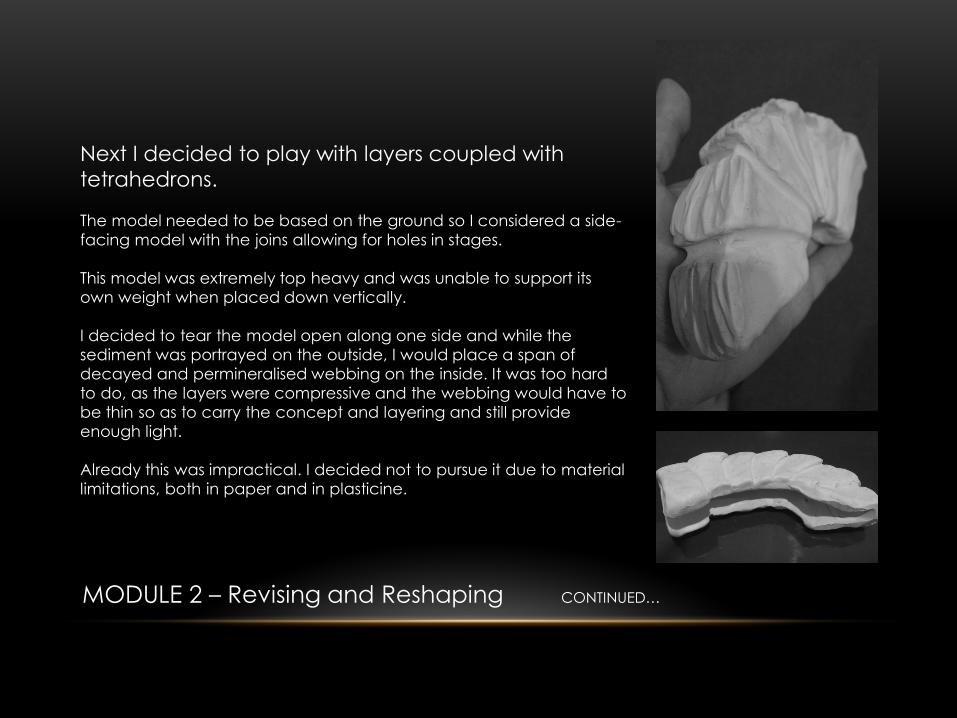
Next I decided to play with layers coupled with
tetrahedrons.
The model needed to be based on the ground so I considered a side-
facing model with the joins allowing for holes in stages.
This model was extremely top heavy and was unable to support its
own weight when placed down vertically.
I decided to tear the model open along one side and while the
sediment was portrayed on the outside, I would place a span of
decayed and permineralised webbing on the inside. It was too hard
to do, as the layers were compressive and the webbing would have to
be thin so as to carry the concept and layering and still provide
enough light.
Already this was impractical. I decided not to pursue it due to material
limitations, both in paper and in plasticine.
MODULE 2 – Revising and Reshaping CONTINUED…
Concept Solid Neg. Space Neg. + Solid Light
Decay Black Forms Holes in Black Black Inner Cavity w/
Conical Holes
-
Permineralisation Quadrilaterals Holes in White White Outer Cavity
and Shadowing with
Holes for direct Light
Light
Represents
Minerals
Forming
Sedimentation Horizontal Levels - Layering of Light and
Dark on White +
Black
Emphasizes
Layers
Mineral Deposits Vertical Levels - The abstracted
image of water and
minerals seeping in
towards the decay
Emphasizes
Minerals, (must
be shaped as
a square)
Inner Layer Arches - Black minerals
Outer Layer Inverted V’s - White Minerals,
Sedimentation
and decay
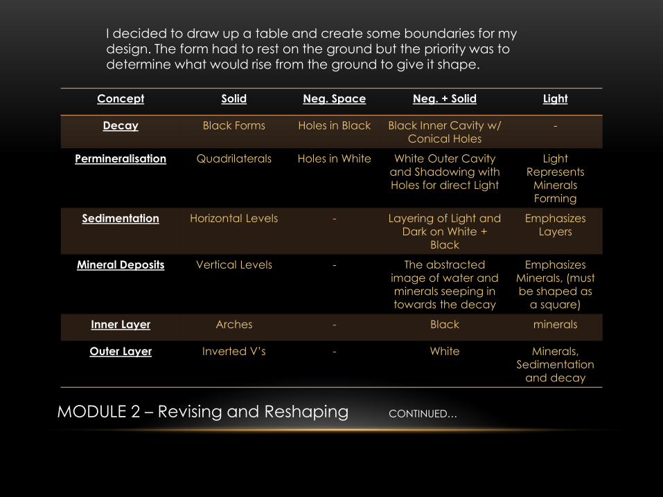
I decided to draw up a table and create some boundaries for my design. The form had to rest on the ground but the priority was to
determine what would rise from the ground to give it shape.
MODULE 2 – Revising and Reshaping CONTINUED…
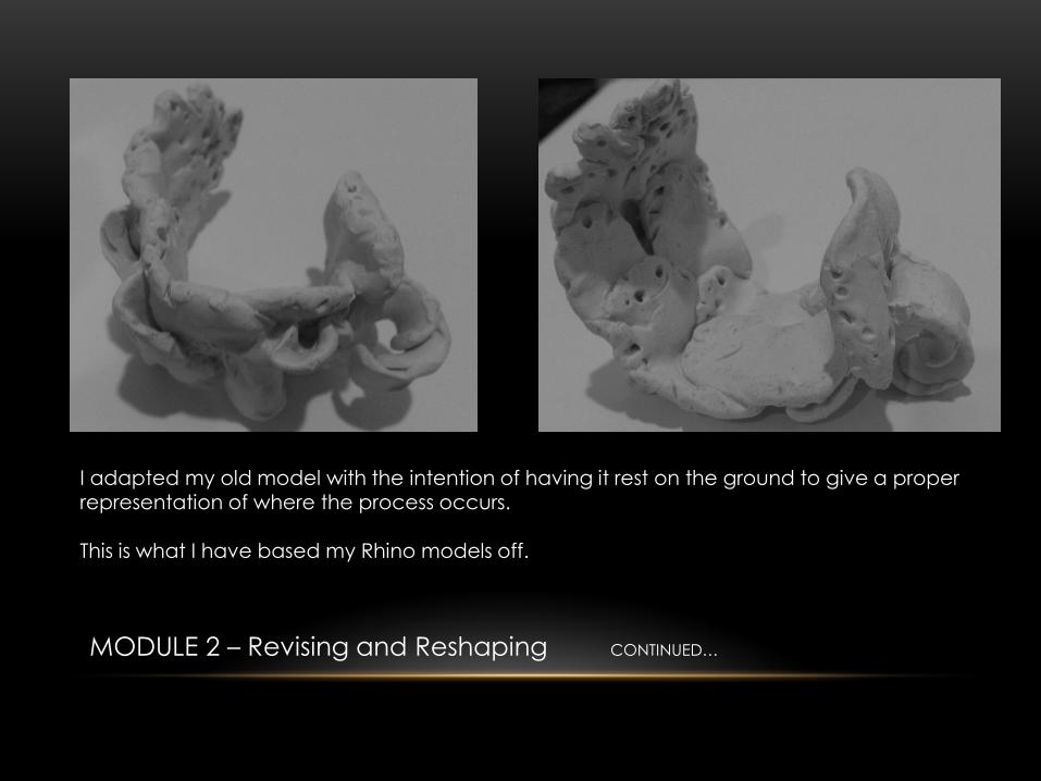
I adapted my old model with the intention of having it rest on the ground to give a proper representation of where the process occurs. This is what I have based my Rhino models off.
MODULE 2 – Revising and Reshaping CONTINUED…
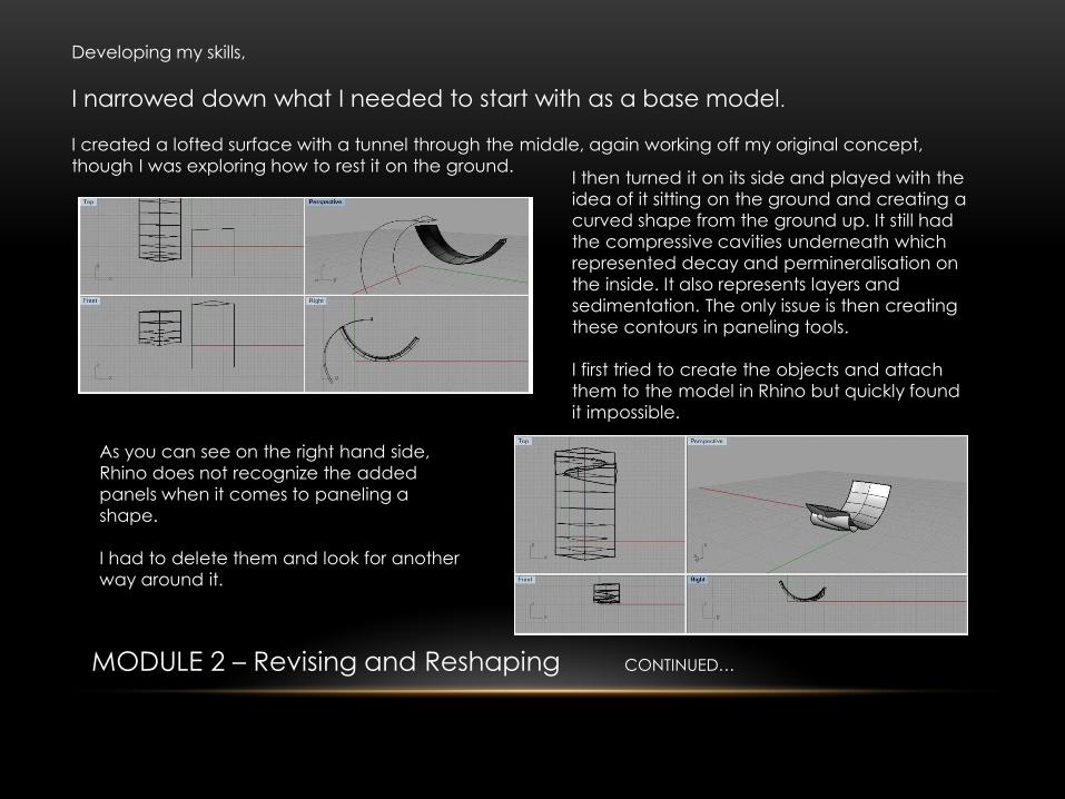
Developing my skills,
I narrowed down what I needed to start with as a base model.
I created a lofted surface with a tunnel through the middle, again working off my original concept,
though I was exploring how to rest it on the ground. I then turned it on its side and played with the
idea of it sitting on the ground and creating a
curved shape from the ground up. It still had
the compressive cavities underneath which
represented decay and permineralisation on
the inside. It also represents layers and
sedimentation. The only issue is then creating
these contours in paneling tools.
I first tried to create the objects and attach
them to the model in Rhino but quickly found
it impossible.
As you can see on the right hand side,
Rhino does not recognize the added
panels when it comes to paneling a
shape.
I had to delete them and look for another
way around it.
MODULE 2 – Revising and Reshaping CONTINUED…
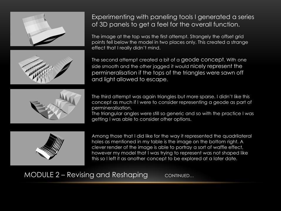
Experimenting with paneling tools I generated a series
of 3D panels to get a feel for the overall function.
The image at the top was the first attempt. Strangely the offset grid
points fell below the model in two places only. This created a strange
effect that I really didn’t mind.
The second attempt created a bit of a geode concept. With one
side smooth and the other jagged it would nicely represent the permineralisation if the tops of the triangles were sawn off and light allowed to escape.
The third attempt was again triangles but more sparse. I didn’t like this
concept as much if I were to consider representing a geode as part of
permineralisation.
The triangular angles were still so generic and so with the practice I was
getting I was able to consider other options.
Among those that I did like for the way it represented the quadrilateral
holes as mentioned in my table is the image on the bottom right. A
clever render of the image is able to portray a sort of waffle effect,
however my model that I was trying to represent was not shaped like
this so I left it as another concept to be explored at a later date.
MODULE 2 – Revising and Reshaping CONTINUED…
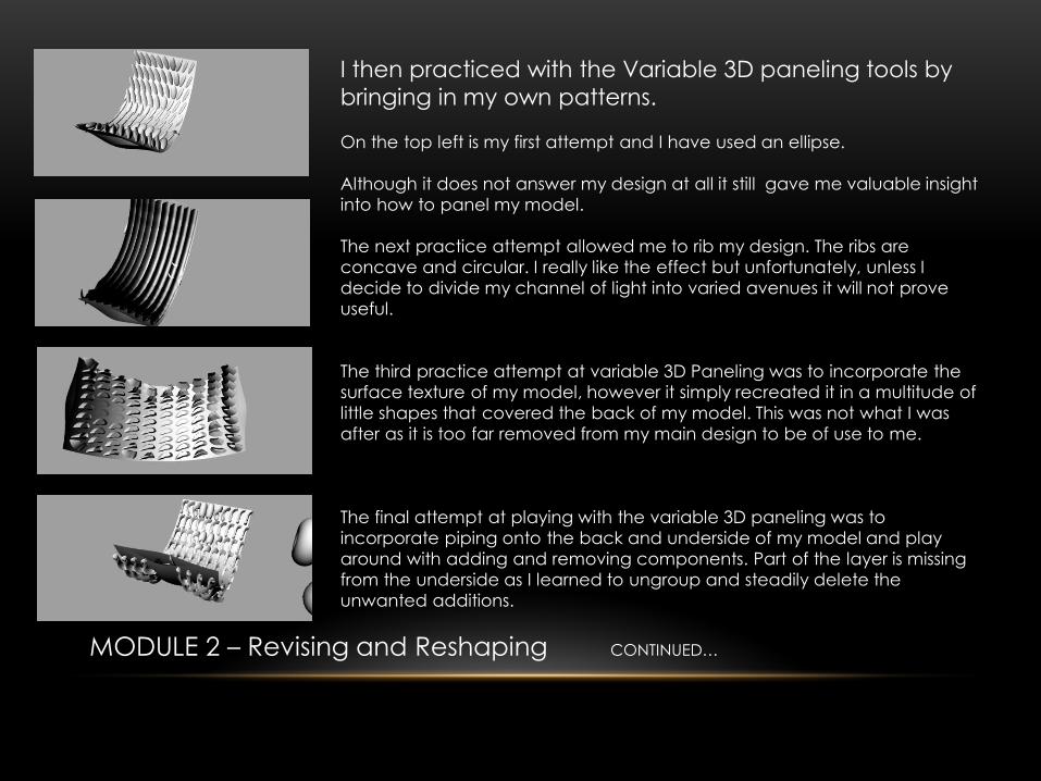
I then practiced with the Variable 3D paneling tools by
bringing in my own patterns.
On the top left is my first attempt and I have used an ellipse.
Although it does not answer my design at all it still gave me valuable insight
into how to panel my model.
The next practice attempt allowed me to rib my design. The ribs are
concave and circular. I really like the effect but unfortunately, unless I
decide to divide my channel of light into varied avenues it will not prove
useful.
The third practice attempt at variable 3D Paneling was to incorporate the
surface texture of my model, however it simply recreated it in a multitude of
little shapes that covered the back of my model. This was not what I was
after as it is too far removed from my main design to be of use to me.
The final attempt at playing with the variable 3D paneling was to
incorporate piping onto the back and underside of my model and play
around with adding and removing components. Part of the layer is missing
from the underside as I learned to ungroup and steadily delete the
unwanted additions.
MODULE 2 – Revising and Reshaping CONTINUED…
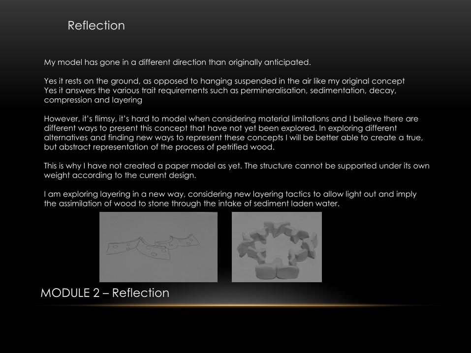
Reflection
My model has gone in a different direction than originally anticipated.
Yes it rests on the ground, as opposed to hanging suspended in the air like my original concept
Yes it answers the various trait requirements such as permineralisation, sedimentation, decay,
compression and layering
However, it’s flimsy, it’s hard to model when considering material limitations and I believe there are
different ways to present this concept that have not yet been explored. In exploring different
alternatives and finding new ways to represent these concepts I will be better able to create a true,
but abstract representation of the process of petrified wood.
This is why I have not created a paper model as yet. The structure cannot be supported under its own
weight according to the current design.
I am exploring layering in a new way, considering new layering tactics to allow light out and imply
the assimilation of wood to stone through the intake of sediment laden water.
MODULE 2 – Reflection
MODULE 3
MODULE 3 – Precedents
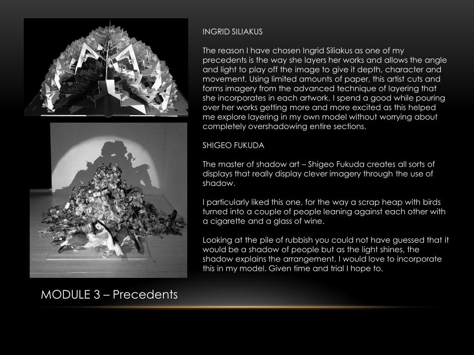
INGRID SILIAKUS
The reason I have chosen Ingrid Siliakus as one of my
precedents is the way she layers her works and allows the angle
and light to play off the image to give it depth, character and
movement. Using limited amounts of paper, this artist cuts and
forms imagery from the advanced technique of layering that
she incorporates in each artwork. I spend a good while pouring
over her works getting more and more excited as this helped
me explore layering in my own model without worrying about
completely overshadowing entire sections.
SHIGEO FUKUDA
The master of shadow art – Shigeo Fukuda creates all sorts of
displays that really display clever imagery through the use of
shadow.
I particularly liked this one, for the way a scrap heap with birds
turned into a couple of people leaning against each other with
a cigarette and a glass of wine.
Looking at the pile of rubbish you could not have guessed that it
would be a shadow of people but as the light shines, the
shadow explains the arrangement. I would love to incorporate
this in my model. Given time and trial I hope to.
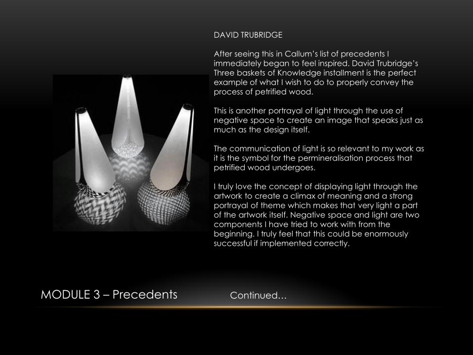
DAVID TRUBRIDGE
After seeing this in Callum’s list of precedents I
immediately began to feel inspired. David Trubridge’s
Three baskets of Knowledge installment is the perfect
example of what I wish to do to properly convey the
process of petrified wood.
This is another portrayal of light through the use of
negative space to create an image that speaks just as
much as the design itself.
The communication of light is so relevant to my work as
it is the symbol for the permineralisation process that
petrified wood undergoes.
I truly love the concept of displaying light through the
artwork to create a climax of meaning and a strong
portrayal of theme which makes that very light a part
of the artwork itself. Negative space and light are two
components I have tried to work with from the
beginning. I truly feel that this could be enormously
successful if implemented correctly.
MODULE 3 – Precedents Continued…
MODULE 3 – The Inspired Design
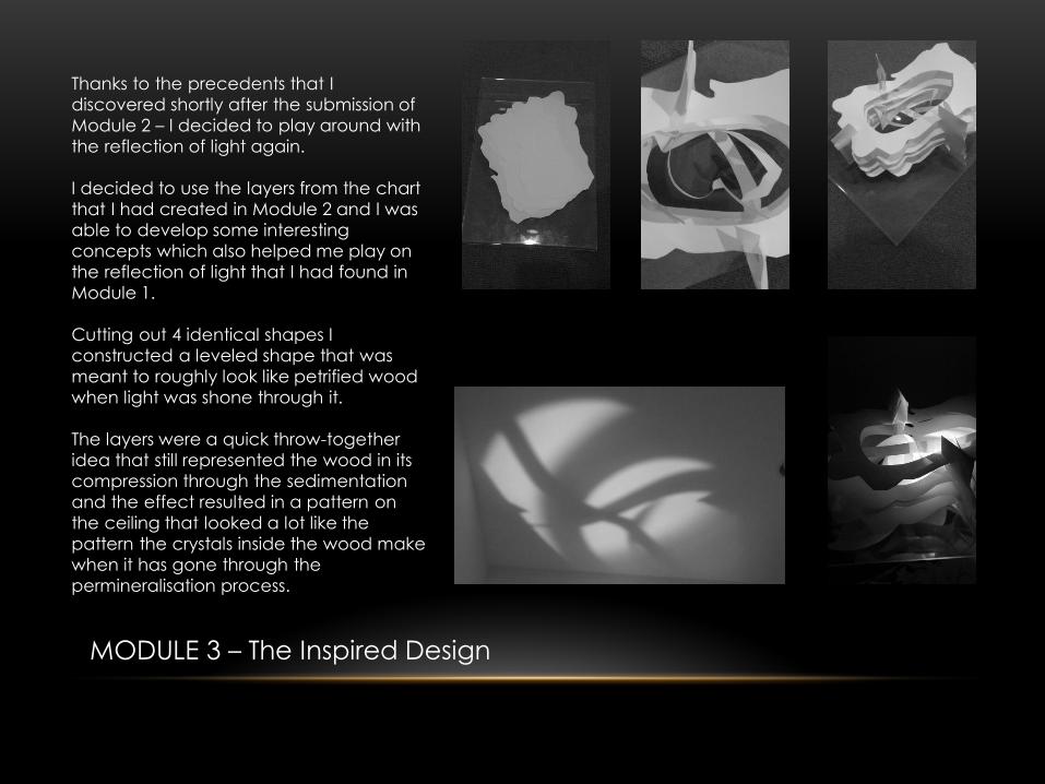
Thanks to the precedents that I
discovered shortly after the submission of
Module 2 – I decided to play around with
the reflection of light again.
I decided to use the layers from the chart
that I had created in Module 2 and I was
able to develop some interesting
concepts which also helped me play on
the reflection of light that I had found in
Module 1.
Cutting out 4 identical shapes I
constructed a leveled shape that was
meant to roughly look like petrified wood
when light was shone through it.
The layers were a quick throw-together
idea that still represented the wood in its
compression through the sedimentation
and the effect resulted in a pattern on
the ceiling that looked a lot like the
pattern the crystals inside the wood make
when it has gone through the
permineralisation process.
MODULE 3 – Key Components Revisited
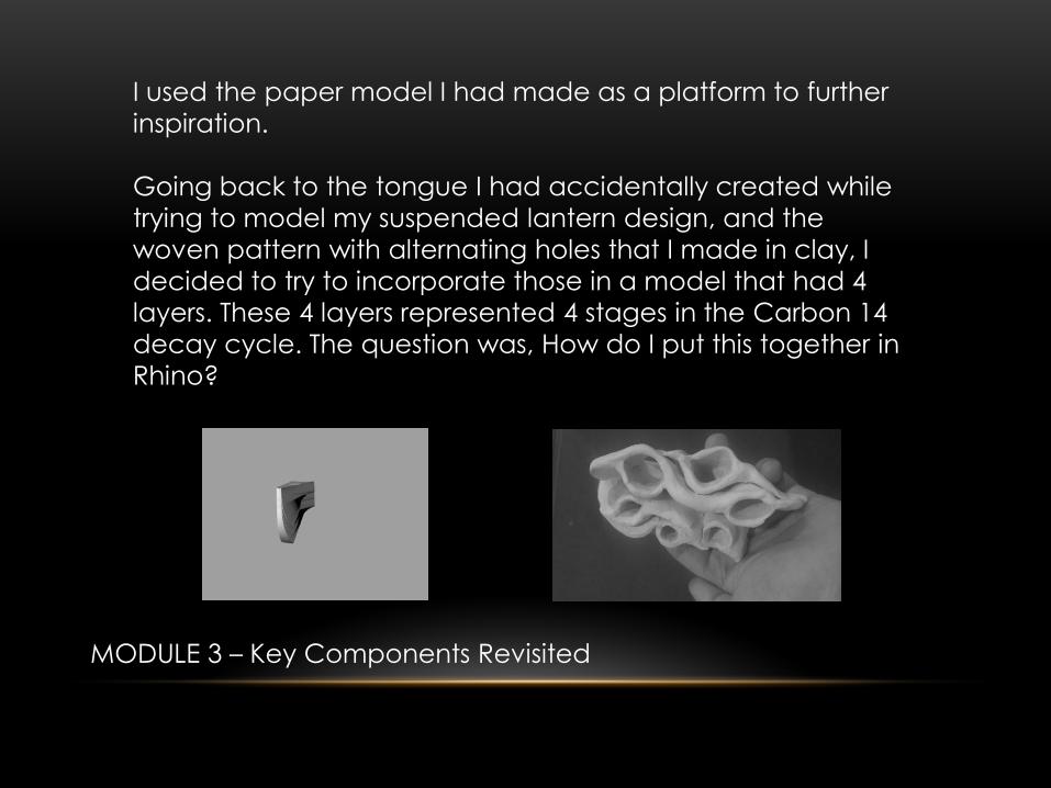
I used the paper model I had made as a platform to further
inspiration.
Going back to the tongue I had accidentally created while
trying to model my suspended lantern design, and the
woven pattern with alternating holes that I made in clay, I
decided to try to incorporate those in a model that had 4
layers. These 4 layers represented 4 stages in the Carbon 14
decay cycle. The question was, How do I put this together in
Rhino?
MODULE 3 – New Idea
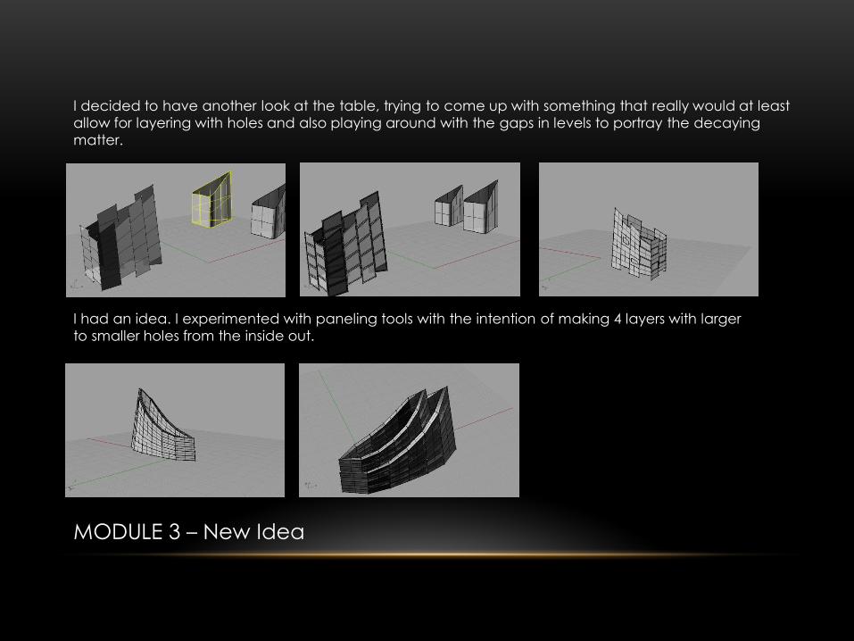
I decided to have another look at the table, trying to come up with something that really would at least
allow for layering with holes and also playing around with the gaps in levels to portray the decaying
matter.
I had an idea. I experimented with paneling tools with the intention of making 4 layers with larger
to smaller holes from the inside out.

MODULE 3 – New Idea Continued…
Realising that I would be
unable to create those
multiple layers within the
bounds of my working
knowledge I instead
lofted a form which
incorporated the outline
of the layers I was hoping
to create.
In this first attempt I have
created some very sharp
edges and layers that I
have later modified to sit
higher.
I got this idea from my
previous ideas in module 1,
where I have essentially
created horizontal areas that
are riddled with holes. The
intention was to panel this
form and introduce those
holes along the horizontal
planes in the levels.
I experimented with this to
learn what to work with. For
my final model.

MODULE 3 – Fabrication
I worked with the model a little more, tweaking the circular
rings to give the model less of a dip between the vertical
panels as any area that did have holes paneled into it would
be weaker than those that were solid.
I actually had a bit of trouble when I unrolled the model for
the first time. Making tabs was among the hardest part of this
model as I was going t o end up with a part-shadow on the
joins which I didn’t want. The alternative would be to create
tabs on each side of the groups and have those tabs sticking
out inside the model which was also undesirable. I decided I
liked the idea of shading and creating a patched effect.
Therefore I decided to try to cover whole portions of groups
by grouping the triangles next to the groups in a fairly even
way. This would allow the pieces to link in and under greater
light show an alternating pattern of light and dark
The image at the bottom is where I have done just that.
After ungrouping the components, arranging them and
exploding the surfaces I sent it in to the fab lab. Taking heed
of their advice I did create some external edges that were to
be scored only so that the model stayed in the card until i
chose to remove the pieces.

MODULE 3 – Fabrication Continued…
Once I received my model back from
the fablab I raced home to place it
together.
Upon getting it home I realised that the
white paper had a lot of burn marks,
there were palaces that I had indicated
be scored that had received nothing at
all and had be estimated and the pen
likewise didn’t always have a complete
score and so I had an interesting time
trying to piece what I had together.
As a result though, I have realised that
while it would also answer my design
better to use black card, for the simple
reason of aesthetics when using a laser
cutter, it would be better to go with a
card that did not show these when the
model was constructed. Unfortunately
the marks showed on the front and the
back so there was no escaping the
visual blemish.

MODULE 3 – Fabrication Continued…
Here is my model actually being constructed
in stages. The angular tabs matched up to the
group either side of it.
There were a couple of incidents of overlap
which I have since remedied by selecting the
tabs of alternating groups on the right hand
side only.
MODULE 3 – Fabrication Continued…
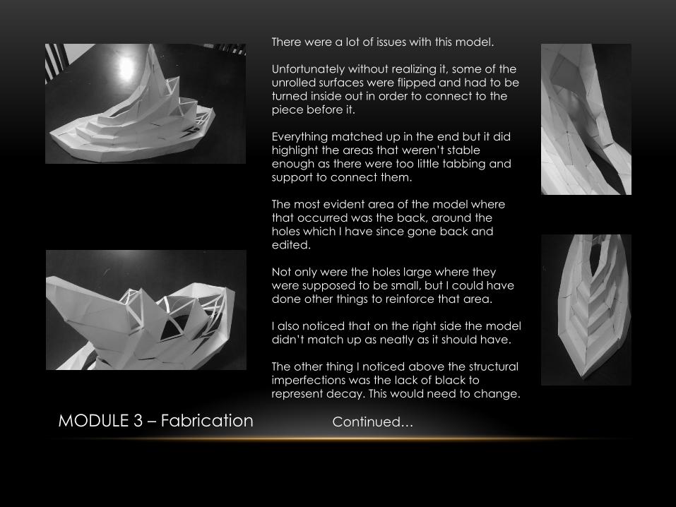
There were a lot of issues with this model.
Unfortunately without realizing it, some of the
unrolled surfaces were flipped and had to be
turned inside out in order to connect to the
piece before it.
Everything matched up in the end but it did
highlight the areas that weren’t stable
enough as there were too little tabbing and
support to connect them.
The most evident area of the model where
that occurred was the back, around the
holes which I have since gone back and
edited.
Not only were the holes large where they
were supposed to be small, but I could have
done other things to reinforce that area.
I also noticed that on the right side the model
didn’t match up as neatly as it should have.
The other thing I noticed above the structural
imperfections was the lack of black to
represent decay. This would need to change.

MODULE 3 – Lighting
The Light shining in the model is
enough to basically give an outline
but it is not strong enough to
expose the flaws in the work.
This was done using the LEDs that
were acquired from the fab lab.
Then this model is exposed to an
intense light the imperfections and
the reflection are much more
visible which only further highlights
the need for another make-over.

MODULE 3 – Revising the Model
Revisiting the model with a list of changes to make I started by increasing the breadth of card
around the holes. I also gave smaller holes to the outer portion of the model and the larger holes to
the inner section as permineralisation generally occurs from the inside out.
Overall,
I still need to toy with the way the pieces connect, the way the image is displayed through the show of light and amount of light that permeates the lamp. At the moment the surrounding area is too dark What I feel I have answered really well is the way it does sit on the ground. It is like this as the wood in a prone form before the process begins. It is only fitting that my
process starts in the same manner. I’m also proud of the layering. I feel it aptly shows sedimentation. I believe that the use of white in the sedimentation does detract from the decay and so I have decided not to include it in any later models despite my chart. I feel that this is a component that can be sacrificed for the good of the overall concept.
I’m still hoping to develop the decay further but I have done so in rhino with a newer model that takes into account the correct degree of decay down the model and the concept of black to really represent the organic matter. It is the token of saying fading to black to explain to concept of decay or dissipation. I am fairly happy with how far I have come but I feel it does still need more
tweaking and editing before the final model.
MODULE 3 – Critical Analysis
REFERENCES
springs ideas: http://www.masterspring.com/images/compression_springs(bjt042).gif Manganites and Cupite: (researching tetrahedral constructs which gave me an idea for my texture) http://sartbaeva.chem.ox.ac.uk/Research_component.html Inverted pyramids in architecture: http://inhabitat.com/the-victoria-albert-museum-as-a-daylit-inverted-pyramid/va-museum-at-dundee-by-rex-2/?extend=1 also: http://www.rex-ny.com/work/v-a-at-dundee http://www.tempe.gov/historicpres/HE-HistoricEligible/CityHall.html Tension and compression: http://www.mercedes-benz-classic.com/content/classic/mpc/mpc_classic_website/en/mpc_home/mbc/home/museum/impressions.flash.html and http://www.e-architect.co.uk/images/jpgs/stuttgart/mercedes_benz_museum_un131108_3.jpg Coils in structures: http://www.civilengineergroup.com/tension-compression-yin-yang-structural-engineering.html Examples of Petrified Wood: http://www.rainbowpetrifiedwood.com/ For the purposes of emphasizing the negative space in order to show degeneration of organic matter I have opted to introduce holes. These holes harbor the light and allow it to glow through.. this is sort of what I was thinking of. Sort of. http://www.etruxes.com/architecture/tapered-circles/ To explain the radioisotope of Carbon: http://www.yellowtang.org/images/carbon_isotope_b_c_la_784.jpg Pixelation http://www.weheart.co.uk/2010/07/28/digital-orca-by-douglas-coupland/ http://cdnimg.visualizeus.com/thumbs/2b/0d/compression,humour,motivational,poster-2b0ded17843e7401263f6276ebbe5a63_i.jpg http://www.jeanniejeannie.com/wp-content/uploads/2011/01/pixelpour22.jpg http://inhabitat.com/the-cloud-mvrdvs-luxury-twin-towers-joined-by-a-lush-pixelated-cluster-in-seoul/the-cloud-mvrdv-1/?extend=1 Carbon-14 Radioisotope http://www.bbc.co.uk/schools/gcsebitesize/science/images/addgateway_graphccad.gif