module 4: type iii or ordinary...
TRANSCRIPT

PRINCIPLES OF BUILDING CONSTRUCTION: COMBUSTIBLE
MODULE 4: TYPE III OR ORDINARY
CONSTRUCTION
OBJECTIVES
At the conclusion of this module, the students will be able to:
1. Identify and describe the characteristics of ordinary (NFPA Type III) construction.
2. Identify the strengths and concerns for ordinary construction.
3. Identify and justify critical construction features for fire, heat, and smoke travel when given a scenario for an ordinary construction.

TYPE III OR ORDINARY CONSTRUCTION
SM 4-2

TYPE III OR ORDINARY CONSTRUCTION
SM 4-3
CHARACTERISTICS OF ORDINARY CONSTRUCTION
The National Fire Protection Association (NFPA) Standard 220, Standard on Types of Building Construction, defines Type III construction in the following manner: "Type III construction shall be that type in which the exterior walls and structural members that are portions of the exterior wall are of approved noncombustible or limited-combustible materials and interior structural members, including walls, columns, beams, girders, trusses, arches, floors, and roofs are entirely or partially of wood of smaller dimensions than required for Type IV construction or of approved noncombustible, limited-combustible, or other approved combustible materials. In addition, structural members shall have fire resistive ratings not less than those specified in Table 3-1."
Table 3-1 Fire Resistance Rating (in hours) for Type I through Type V Construction
H2
443
Type IIIType IIType I Type IV Type V
332 211111 000222 200 2HH 111 000
Exterior Bearing Walls -Supporting more than one floor,
columns, or other bearing walls……..Supporting one floor only……………..Supporting a roof only…………………
Interior Bearing Walls -Supporting more than one floor,
columns, or other bearing walls……..Supporting one floor only……………..Supporting a roof only…………………
Columns -Supporting more than one floor,
columns, or other bearing walls……..Supporting one floor only……………..Supporting a roof only…………………
Beams, Girders, Trusses& Arches -Supporting more than one floor,
columns, or other bearing walls……..Supporting one floor only……………..Supporting a roof only…………………
Floor Construction
Roof Construction
Exterior Nonbearing Walls
444
333
221
111
01
01
01
222
222
222
111
01
01
01
000
433
433
333
221
111
000
111
211
111
000
322
221
111
000
000
111
111
H2
H2
H2
000
433
322
221
111
000
000
111
111
H2
H2
H2
000
H23 2 2 1 0 1 0 1 0
1 0 1 0
01 01 01 010101010101
2 1 1/2 1 1 0
Those members that shall be permitted to be of approved combustible material.
1 See A-3-1 (Table).2 "H" indicates heavy timber members; see text for requirements.
01
Reprinted with permission from NFPA 220, Types of Building Construction, Copyright © 1995, National Fire Protection Association,Quincy, MA 02269. This reprinted material is not the complete and official position of the National Fire Protection Association, on the referenced subject which is represented only by the standard in its entirety.

TYPE III OR ORDINARY CONSTRUCTION
SM 4-4
Notes regarding Table 3-1:
1. Only exterior bearing walls must be constructed of noncombustible materials, while interior bearing walls, columns, beams, girders, trusses, arches, floors, and roofs may be constructed with combustible material, that has been provided with an appropriate level and approved method of fire resistance.
As an example, wood could be covered in an appropriate manner with gypsum board of an appropriate depth to create a 1-hour fire-resistive structural element.
2. The requirements for fire resistance of exterior nonbearing walls located in close proximity to property lines, other buildings, or exposures, the provision of spandrel wall sections, and the limitation of protection of wall openings are not related to type of construction. They might be specified in other standards and codes, where appropriate, and might be required in addition to the requirements of this standard for the type of construction.
As an example, a community may establish an area as having "Fire Limits" which typically either requires a significant separation of buildings from each other or requires the exterior walls to be made from noncombustible materials. Many of these Fire Limits were established in communities to prevent conflagrations that often occurred when wood-frame buildings were placed close to each other.
3. The identification of a 211 or 200 Type III building is a subclassification for this method of construction. It often is used by municipalities to identify a specific type of construction with its appropriate fire resistance.
As an example, a municipality may allow only a Type III--211 building to be constructed on a particular building lot or for a specific occupancy where a higher level of fire resistance is desired.

TYPE III OR ORDINARY CONSTRUCTION
SM 4-5
Main Street USA
Other common terms applied to Type III or ordinary construction are "Main Street USA," and a "Taxpayer." The term "Taxpayer" evolved from "Main Street USA," where a building owner would operate a retail store on the first floor and live in an apartment on the second floor. It was said that the property taxes for the building were paid for by the store's income, and the shop owner lived above the store tax free.
Buildings of ordinary construction generally are built no taller than six to eight stories due to the thickness of the supporting walls required to support the floor loads above the ground. The tallest building of ordinary construction is located in Chicago, Illinois, and is 15 stories high. Most ordinary-construction buildings on "Main Street" are only two or three stories high.
Exterior Wall Construction
Exterior walls of ordinary construction generally are constructed of brick. A true brick wall is two or more courses of brick thick. If a solid brick wall is being built, it is customary to lay five to six layers of brick lengthwise (stretcher rows) in the wall and then lay one at a 90-degree angle (header row) to the courses of brick below. This serves to tie the wall together as a solid unit. The bricks laid lengthwise are called "stretchers" and the rows laid at a 90-degree angle, where only the end of the brick is seen, are called "headers." Some walls have been constructed with the headers laid in a pattern in every course or every other course. This usually will be represented by a header, one or two stretchers, and another header with the pattern repeated. One continuous vertical section of masonry wall one brick in thickness is called a "wythe." A true brick wall has two or more wythe, while a fascia or decorative wall will have only one wythe of brick. In reading a building, the fact that there are both headers and stretchers could be one indication that it is a solid brick wall.

TYPE III OR ORDINARY CONSTRUCTION
SM 4-6
Solid Walls
6th Course Headers Common Bond
(Typical)
Another material commonly used for exterior wall construction is concrete block. The block is the load-bearing wall and carries the loads above. Often the wall is faced with a brick veneer finish to resemble a brick building. During the installation of the block wall, metal wall ties (small strips of metal) are laid every two or three rows of blocks in the mortar between the blocks. When the veneer brick wall is constructed the wall ties are installed in the mortar to tie the brick wall to the block wall. The brick wall is one brick wide and the same height as the block wall.
This same technique is used for other types of buildings, such as wood frame, where a brick veneer may be used as the exterior finish. In this case, the metal wall ties are nailed onto the wooden studs. Without some type of support, the brick wall would float and possibly tip over. If the brick veneer wall is being installed at the same time as the block wall, a lightweight steel reinforcing truss can be applied every two or three courses between both the block wall and the brick wall in place of the wall ties.
Some older buildings used a clay terra cotta block in place of today's modern concrete block as the load-bearing wall. Terra cotta is a material similar to brick, which is fired in a kiln to harden the material. A tile used to line a chimney is similar to that used for wall construction, except that the construction tile has numerous divisions inside the tile for strength. The terra cotta block wall was brittle and subject to being broken when struck with heavy objects. The exterior wall was faced with one layer of brick similar to the technique used for block walls. One danger of veneered walls placed adjacent to block walls is that it is possible, through various building connections, that gases from a fire, such as carbon monoxide, could accumulate in the small cavity between the two walls.

TYPE III OR ORDINARY CONSTRUCTION
SM 4-7
Cavity Walls
Reinforced Walls Solid Wall
Wall thickness of a Type III building typically will range from 6 to 30 inches thick, depending upon the load it must carry. Remember that every ounce of weight from the roof load through the first floor of the building must be carried and transmitted to the foundation of the building.
Bearing walls carry the load of the structure, which is transferred to the wall from the floor joists and roof rafters. Failure of a load-bearing wall can result in catastrophic structural collapse. It is critical that all emergency scene personnel be able to identify the load-bearing walls and understand the dangers associated with wall failure. Bearing walls are typically the longest walls of the structure. This may be the front (street side) or, most
3 r d F l o o r1 2 "
2 4 "2 n d F l o o r
1 s t F l o o r
3 6 "

TYPE III OR ORDINARY CONSTRUCTION
SM 4-8
often, the sides of the building. The longest walls typically are used to support the load, since this requires the shortest span for the floor joists and roof rafters inside the building.
Walls may have a heavy load that may push in a lateral manner instead of directly downward on the wall, and tend to tip the wall outward. This often happens when loads are applied directly against the walls, or when large open areas lack adequate materials to tie the two walls together, such as when cathedral ceilings are built improperly. To counteract the push against the walls a masonry pier can be built into the block wall, a buttress (brace larger at the bottom than at the top) can be installed, or tie cables and rods can be installed, which is the most common method. The concern for the steel tie rods and cables is that they are subject to relaxation or elongation when heated, thus allowing the walls to move. The rods and cables are connected with turnbuckles that can be adjusted to compensate for the load applied above.
Load-Bearing Walls Curtain Walls
Common walls between two buildings often were used in ordinary construction. This was particularly true when the same developer was constructing multiple buildings adjacent to each other. The single wall not only separated the two buildings, but also provided the support for a load-bearing wall for both buildings. A catastrophic event, such as an explosion, on one side of the wall could have catastrophic results for the neighboring building if the common wall was damaged. As the buildings were constructed, a joist pocket would be built into the wall and the floor

TYPE III OR ORDINARY CONSTRUCTION
SM 4-9
joists or roof rafters from both buildings would share the opening in the wall. This "good-neighbor policy" also raises concerns under fire conditions, with the potential for fire to extend from one building into the next through the common wall joist pocket. A typical tactical objective is to enter the exposure building and open ceilings to inspect for common joist pockets and to evaluate fire, smoke, or heat travel. Another concern if a significant fire should occur in one building and the structural supporting members holding the floors and roof should be lost is that the load applied to the common wall is totally from one side. This could raise concerns for the possibility of collapse. Often, when a building has been removed from one side of a common wall, special bracing is provided for the wall. To keep floor joists from pushing the wall down should they fall from the joist pocket, the floor joists were cut on an angle which is called a "fire cut." The fire cut provided the maximum surface for the joist to rest on the bottom, but was cut to provide minimum clearance for the top of the joist pocket.
All loads above the foundation must be transmitted to the foundation. This is especially critical when openings in the load-bearing walls must be spanned for windows, doors, or other structural features. The entire load above the opening must be carried and transferred to the wall at some other point which usually is directly adjacent to the opening. The load can be carried and transferred back to the wall with a lintel or an arch. A lintel is typically a steel angle iron placed at the top of the opening and resting on the walls adjacent to the opening. An arch is made from stone or masonry materials, and each component is dependent on the element next
TYPE III OR ORDINARY CONSTRUCTION
SM 4-10
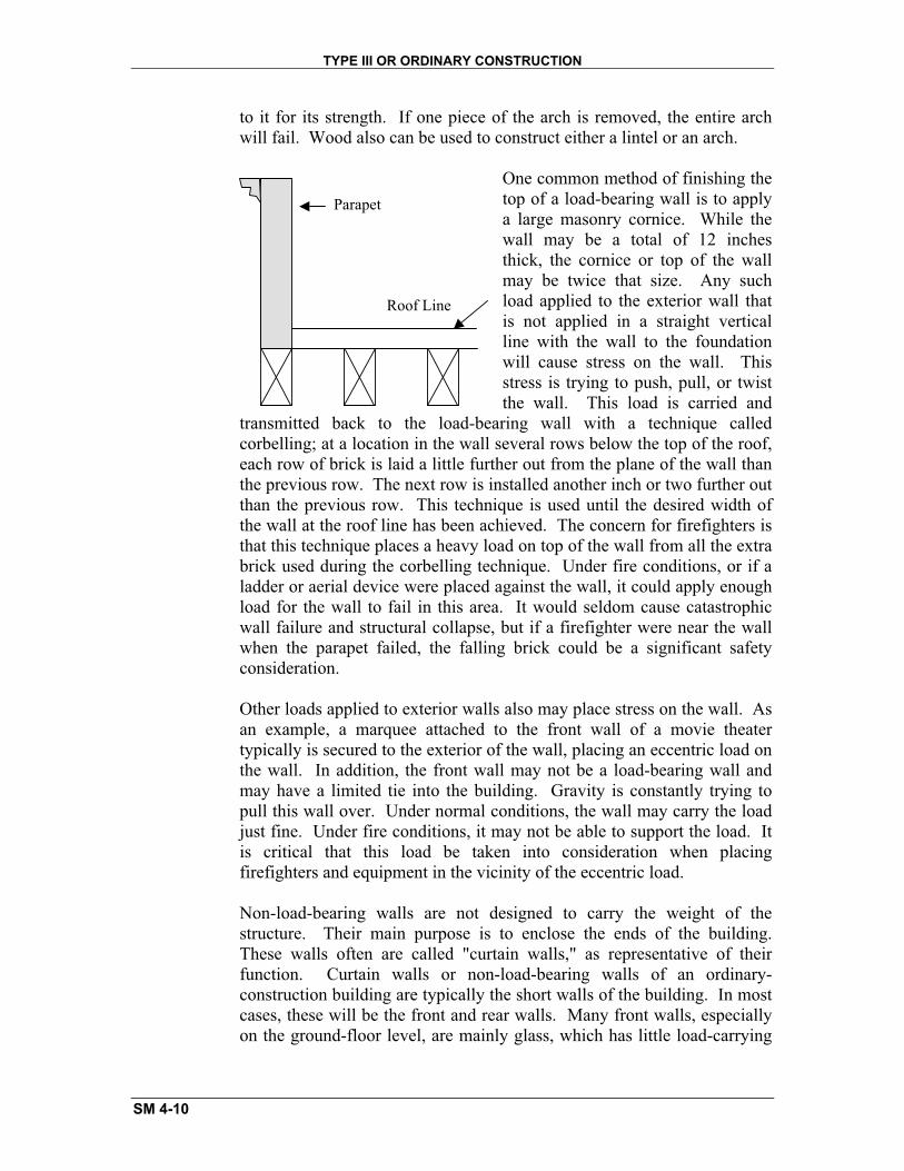
Roof Line
Parapet
to it for its strength. If one piece of the arch is removed, the entire arch will fail. Wood also can be used to construct either a lintel or an arch.
One common method of finishing the top of a load-bearing wall is to apply a large masonry cornice. While the wall may be a total of 12 inches thick, the cornice or top of the wall may be twice that size. Any such load applied to the exterior wall that is not applied in a straight vertical line with the wall to the foundation will cause stress on the wall. This stress is trying to push, pull, or twist the wall. This load is carried and
transmitted back to the load-bearing wall with a technique called corbelling; at a location in the wall several rows below the top of the roof, each row of brick is laid a little further out from the plane of the wall than the previous row. The next row is installed another inch or two further out than the previous row. This technique is used until the desired width of the wall at the roof line has been achieved. The concern for firefighters is that this technique places a heavy load on top of the wall from all the extra brick used during the corbelling technique. Under fire conditions, or if a ladder or aerial device were placed against the wall, it could apply enough load for the wall to fail in this area. It would seldom cause catastrophic wall failure and structural collapse, but if a firefighter were near the wall when the parapet failed, the falling brick could be a significant safety consideration.
Other loads applied to exterior walls also may place stress on the wall. As an example, a marquee attached to the front wall of a movie theater typically is secured to the exterior of the wall, placing an eccentric load on the wall. In addition, the front wall may not be a load-bearing wall and may have a limited tie into the building. Gravity is constantly trying to pull this wall over. Under normal conditions, the wall may carry the load just fine. Under fire conditions, it may not be able to support the load. It is critical that this load be taken into consideration when placing firefighters and equipment in the vicinity of the eccentric load.
Non-load-bearing walls are not designed to carry the weight of the structure. Their main purpose is to enclose the ends of the building. These walls often are called "curtain walls," as representative of their function. Curtain walls or non-load-bearing walls of an ordinary-construction building are typically the short walls of the building. In most cases, these will be the front and rear walls. Many front walls, especially on the ground-floor level, are mainly glass, which has little load-carrying

TYPE III OR ORDINARY CONSTRUCTION
SM 4-11
capability. In many instances during building renovations, the front wall of a building has been partially or totally removed and the building remains standing with a minimum of bracing.
The non-load-bearing walls typically carry an end of the carrier beams for the floor joists and roof rafters. Since the curtain walls do not have a heavy load applied to them they often are held in place with metal rods. The rods pierce the exterior wall with some type of washer. The washer, which may be a round or square piece of steel plate or, in some cases, a decorative washer in the form of a star, is used to expand the surface area of the tie rod against the wall. The tie rod typically will go into the structure through two or three floor joists and be secured into the floor joist that runs parallel to the front curtain wall. The tie rod is threaded, and will have a nut and washer adjusted against the other floor joists it passes through. This technique allows the load being transferred to the floor joists to be distributed over two or three joists. When reading a building, if tie rods are observed, there are several considerations that must be made. Tie rods through a front curtain (non-load-bearing) wall may have less significance than tie rods or cables through a side (load-bearing) wall. Failure of the rods or cables through a bearing wall may cause catastrophic structural failure during a fire, while failure of the rods in a curtain wall simply may allow the wall to separate from the building and collapse without total structural failure.
Many buildings have had cosmetic applications to cover deficiencies. This may be a brick wall with mortar missing or deteriorated brick. On block walls it may be used to cover sections that have settled or shifted, causing a portion of the wall to separate from the rest of the wall. Once the integrity of the mortar has been broken and the block shifted, this wall will no longer act as one unit and may be subject to shifting or partial collapse. The most common method to provide a cosmetic cover is with a stucco or plaster mix applied over the exterior wall. This technique is called "parging."
Interior Wall Construction
Interior walls for Type III buildings are most often wood. The wood may be 2 by 4 or 2 by 6 inches. A lot of renovation or new construction uses sheet metal studs formed in the shape of a "C" with two 2-inch sides and the section between 4 inches; this resembles a "C" with square corners. These studs are predrilled for wiring to pass through. The metal studs most commonly are connected with metal screws, screw nails, or pop rivets. In older construction the studs were covered with wood lath and a coat of plaster. Wood lath is an ideal fuel source; it has a rough surface with a lot of surface area due to the small splinters of wood attached to the
TYPE III OR ORDINARY CONSTRUCTION
SM 4-12
lath. This lath, in comparison to a planed and smooth surface of a wall stud, has a great deal more available fuel surface area per square inch of wood than the dimension lumber. Therefore, a fire in a wall stud channel with wood lath would have an excellent dry, abundant, and perfectly arranged fuel source.
In recent years, the wall covering applied to the studs has been gypsum board, more commonly called "drywall board." Typically, the building support systems, such as plumbing, heating, and electrical systems, traverse the interior walls and may create open voids for fire extension and travel. Often when these buildings are renovated, new utilities are installed in a corner of a room and a new wall is used to box around the utility services. Interior walls often provide critical support to carry the load of the floors above and the roof. While the exterior loads are carried on the load-bearing walls, the remainder of the load must be carried by the interior walls.
Often, an older building is modernized or an occupancy is changed and newer, heavier loads are placed inside the structure with new coolers, freezers, or air conditioning units placed on the roof. The closer these loads are placed to the outside load-bearing walls the better. Another common problem occurs when a retail store on the first floor is expanded into an adjoining unit. An ordinary building typically would have two separate stores on the ground level separated by an interior wall which is supporting the load of the floors above. When a retail store is expanded into the other side, the temptation is to remove the wall between the two units so customers and employees can move easily from one side to the other. It is critical that the load be carried over. Support columns on the floor below will need to be braced to carry the additional concentrated load.
Floors
Floors of Type III or ordinary construction are typically one of the strengths of this type of construction. When the Type III buildings were constructed, floor joists usually were 3 by 10 inches in dimension or larger for the first floor, and placed 12 inches on-center. This provided a great deal of strength to carry loads placed on the floors, especially for the retail stores. Floor joists for the floor(s) above may use smaller dimension lumber such as 2 by 8 inches. Another important aspect was the fact that the floor joists placed in wall sockets on the load-bearing wall were cut on an angle so that, should a fire occur and the interior of the building be burned away, it could fall into the interior of the building without causing the wall to collapse. This was called a "fire cut," where the end of the joist or rafter is cut so that the top is shorter than the bottom. Should it fall

TYPE III OR ORDINARY CONSTRUCTION
SM 4-13
from the socket of the interior it would do so without causing the joist or rafter to act as a lever and push the top of the wall outward, as it would had it been cut at a 90-degree angle.
Ceilings usually are attached to the floor joists above. Commonly, a wood strip called a "furring strip" would be attached to the bottom of the joist and ceiling materials attached. This material may be lath and plaster, sheet metal plates, ceiling tile, or gypsum board. The original ceilings were high to compensate for the lack of air conditioning. Over the years, many of these ceilings have been lowered, with a metal-grid-and-ceiling-tile method being the most common. This creates void areas for fire travel. It is always a good strategic consideration to check for fire extension, with the tactical objective being to open the ceiling to inspect for fire travel. Some support for the floors above included cast iron columns. In addition to the cast iron columns it is critical to look at the method of connection to the carrier beam system to ensure it is properly supported and secured. About the turn of the century, a few buildings were faced with a cast iron front. These fronts may have limited load-carrying capability for the curtain wall, but more often were used for their decorative purposes.
Roofs
Roofs are installed on ordinary construction using a variety of methods. The most basic roof is sloped from the front wall to the rear wall with an adequate slope to provide drainage. Another method is a nearly flat roof with just enough slope to drain the water to centralized roof drains with a piping system which brings the water from the roof to the basement and sewer system. A third type is a peaked roof with roof drains at the lowest ends of the roof pitches. Roof rafters are placed on a support system that carries the exterior roof load to the load-bearing walls, similar to the floor joists below. In newer buildings the roof structure may be constructed from truss rafters or from rafters constructed with a wooden "I" beam arrangement. Roof boards or plywood are placed over the rafters and a roofing material is applied. Roof materials may include an asphalt-based paper and hot tar, rubber or vinyl sheets cemented to the roof, or corrugated steel sheets. In some instances an asphalt roof may be covered with a layer of stone to protect the asphalt material from the daily expansion and contraction from the heating and cooling process. In addition, many vinyl or rubber roofs may be protected with lightweight concrete blocks intended to be used for persons walking on the roof to service equipment located there.

TYPE III OR ORDINARY CONSTRUCTION
SM 4-14
Front
Roof Drains
Front Front
Each roof structure will provide a void area that is a critical concern for fire extension. This area often is referred to as a "cockloft." This cockloft usually is accessible from within the building via a scuttle hole and ladder, commonly placed into the ceiling of the top floor or on a rear porch to provide access. Inside the cockloft there is typically a ladder that leads to a scuttle opening onto the roof. This is an easy access to the roof for maintenance purposes. This scuttle opening also can provide a quick ventilation opening into the cockloft area if ladder access can be gained to the roof from the exterior. Remember that there may be several inches to several feet from the top of the building wall to the roof below. It is critical that building preplans indicate the roof construction and features so that, should roof operations become necessary, critical decisions can be made at the ground level. These would include the construction of the roof, the roof covering, and the tools or equipment needed to open the roof.
Cockloft
Scuttle Cover

TYPE III OR ORDINARY CONSTRUCTION
SM 4-15
Building Renovations
Building renovations are a special concern to firefighters, as they can create some special safety or operations problems. One typical problem is combustible additions being made to the exterior walls, which are of a noncombustible material. A fire in the exterior or wooden addition may extend easily into the ordinary-construction building through unprotected openings. Another typical renovation is the addition of a mansard "eyebrow" onto the exterior wall. This is a typical renovation for buildings used for retail purposes. The mansard may cover over openings into the structure, such as windows. In addition the mansard eyebrow typically is attached to the exterior wall and places an eccentric load on the wall. Mansards are deficient in firestops and commonly are wide open from end to end. Another common concern is the installation of a new roof over the old roof, complete with new rafters. Often, in order to reduce costs of a new roofing system (which would include the removal of the old roof), a new structure is placed over the existing roof creating a void for fire extension. This problem can be encountered during a ventilation effort after the first roof is opened only to find a second roof. It is important to inspect the buildings in your area before a fire occurs and to prepare a Quick Access Prefire Plan (QAP) showing the features or special concerns of the structure.
FIRE TRAVEL CONSIDERATIONS AND FIRE BEHAVIOR PREDICTIONS
Horizontal fire spread on the same floor of Type III buildings is often the result of building renovations that have created void areas. Examples of these void areas include dropped ceilings, walls breached to extend building services such as plumbing, heating, or electrical wires from one area to another, building renovations covered with combustible materials, such as a mansard eyebrow installed on an exterior wall over windows, or joist pockets in common walls where one building's structural member is placed alongside the neighbor's joist or rafter.
Often, vertical fire spread from floor to floor is caused by vertical voids created during renovations, or by updating the building's utility services. Utility shafts often pass from floor to floor, and have openings that allow fire to spread floor to floor. Other openings that penetrate the floors and provide an opportunity for vertical fire spread include elevator shafts, dumbwaiter shafts, and trash chutes. It is typical that Type III buildings have open stairways without fire doors or separations. A fire that enters or starts in the common hall, quickly spreads to the upper floors. Many older buildings were finished with wood paneling or partially finished with wainscotting (wood about halfway up the wall from the stair treads).
TYPE III OR ORDINARY CONSTRUCTION
SM 4-16
The potential for collapse always must be considered. The load-bearing walls should be evaluated carefully for areas of deterioration, areas that appear to be carrying extremely heavy loads, or signs that the walls may push outward, such as an area with metal washers and bolts on the load-bearing walls. Also check for load-transfer methods used over doors, windows, or areas where the walls have been breached and not properly reinforced with a lintel. In many instances walls are breached to install items such as air conditioning units by removing a few blocks or bricks from a wall to install the metal case for the air conditioning unit. This metal case does not replace a lintel, and the load above may not be transferred properly.
Any wall being held in place by a cable or steel rods always should be of special interest, since heat can affect the steel and cause it to relax or stretch. As the metal cable or rod stretches, the walls may move outward. When two buildings share a common wall, there is always a concern that fire could move from one building to the other. It is important to check for extension at all levels (floors) and in multiple locations at each level. If an adjoining building that used to share the common wall is gone, the wall may be eccentrically loaded and additional water placed inside by firefighting hose streams, falling structural elements, or other shifts in the building that may cause wall failure.
Non-load-bearing walls (usually the front and rear) are especially vulnerable to failure. Items that may cause failure are especially heavy loads on the wall (such as signs or marquees), mansard roof additions attached to the outside of the wall, wall tie (steel rod) failure, or interior structural collapse.
Older manuals used to have formulas to predict how far the walls would fall if they collapsed. Experience has shown that the distance they will fall is unpredictable. Firefighters have been killed working too close to the curtain walls when they collapsed and fell. As a minimum, a safe distance must include the height of the wall plus a safety margin depending upon conditions at the scene.
SUMMARY
Type III buildings typically will have two load-bearing walls (long walls) and two curtain walls (short walls). The load of the building is placed on the load-bearing walls, which must be transferred to the ground.
Buildings of ordinary construction often are renovated, with new void spaces created. These include horizontal voids created by dropped ceilings and vertical voids through new utility chases.

TYPE III OR ORDINARY CONSTRUCTION
SM 4-17
The cockloft area is particularly vulnerable to rapid fire extension due to the heavy fire load in a confined and open space.
It is extremely important for fire officers, Incident Commanders (IC's), and Safety Officers to read a building's construction carefully before developing their strategic goals or implementing their tactical objectives.

TYPE III OR ORDINARY CONSTRUCTION
SM 4-18

TYPE III OR ORDINARY CONSTRUCTION
SM 4-19
Activity 4.1
Ordinary (Type III) Constuction
Purpose
To apply knowledge of the construction features of an ordinary (Type III) building under fire conditions.
Directions
1. Your group will be assigned one of the three scenarios.
2. Read the scenario, review the slides of the building, and answer the questions below as they relate to your scenario.
a. List specific safety concerns as they pertain to the classification of the building.
b. Has flashover occurred yet? If not, is there a danger of it happening?
c. What method of construction was used for this building?
d. List three positive features of this method of construction.
e. List one special concern for this method of construction.
f. How will fire, heat, and smoke travel through this structure?
g. Would you expect fire suppression to be a significant challenge? Why?
3. Select a spokesperson to record your answers and report the group's findings when your group is asked to report. You have 20 minutes for this activity.

TYPE III OR ORDINARY CONSTRUCTION
SM 4-20
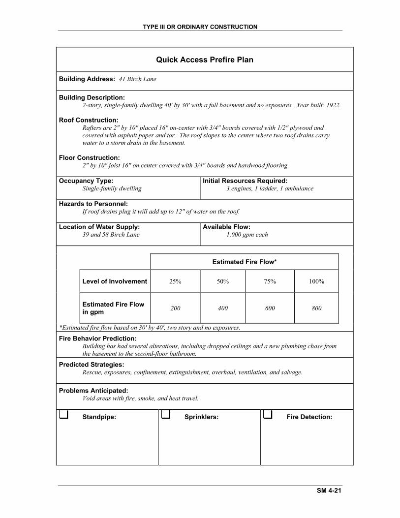
Scenario 1: 41 Birch Lane
A fire has been reported in a single-family residence. The caller reported a smoke condition in the second floor. The caller stated that it has been raining heavily and the roof is leaking at several locations through the second-floor ceiling, including through the light fixtures. The caller also states that normally, during a heavy rain, he/she can hear water running through the drain pipes, but today he/she cannot, which leads him/her to believe the roof drains are plugged. It is 1330 on a Tuesday.
TYPE III OR ORDINARY CONSTRUCTION
SM 4-21
Quick Access Prefire Plan
Building Address: 41 Birch Lane
Building Description: 2-story, single-family dwelling 40' by 30' with a full basement and no exposures. Year built: 1922.
Roof Construction: Rafters are 2" by 10" placed 16" on-center with 3/4" boards covered with 1/2" plywood and covered with asphalt paper and tar. The roof slopes to the center where two roof drains carry water to a storm drain in the basement.
Floor Construction:2" by 10" joist 16" on center covered with 3/4" boards and hardwood flooring.
Occupancy Type: Single-family dwelling
Initial Resources Required: 3 engines, 1 ladder, 1 ambulance
Hazards to Personnel: If roof drains plug it will add up to 12" of water on the roof.
Location of Water Supply: 39 and 58 Birch Lane
Available Flow: 1,000 gpm each
Estimated Fire Flow*
Level of Involvement 25% 50% 75% 100%
Estimated Fire Flow in gpm 200 400 600 800
*Estimated fire flow based on 30' by 40', two story and no exposures.
Fire Behavior Prediction: Building has had several alterations, including dropped ceilings and a new plumbing chase from the basement to the second-floor bathroom.
Predicted Strategies: Rescue, exposures, confinement, extinguishment, overhaul, ventilation, and salvage.
Problems Anticipated: Void areas with fire, smoke, and heat travel.
Standpipe: Sprinklers: Fire Detection:

TYPE III OR ORDINARY CONSTRUCTION
SM 4-22
Scenario 2: 22 Elm Street
A fire has been reported in an office building housing real estate, insurance, and brokerage offices on the first floor and an architect's office on part of the second floor. The other half of the second floor is vacant and for rent. The fire is reported in the insurance office on the first floor. The police officer on patrol reported the fire. It is 0630 on a Tuesday.

TYPE III OR ORDINARY CONSTRUCTION
SM 4-23
Quick Access Prefire Plan
Building Address: 22 Elm Street
Building Description: 2-story building 30' by 70' with no basement and no exposures. The building originally was constructed to house offices for a large knitting mill across the street. The mill offices have been closed and the building was subdivided into 5 offices (3 down and 2 up). Exterior walls are brick. Only a partial basement for boiler. Year built: 1931.
Roof Construction: 2" by 8" rafters 12" on-center covered with 1" boards and asphalt shingles.
Floor Construction:2" by 10" joists 12" on-center covered with 3/4" boards and hardwood floors.
Occupancy Type: Five offices
Initial Resources Required: 3 engines, 1 ladder, 1 heavy rescue
Hazards to Personnel: No special hazards.
Location of Water Supply: 2, 22, and 42 Elm Street
Available Flow: 1,000 gpm each
Estimated Fire Flow*
Level of Involvement 25% 50% 75% 100%
Estimated Fire Flow in gpm 350 700 1,050 1,400
*Estimated fire flow based on 30' by 70', two stories with no exposures.
Fire Behavior Prediction: Dropped ceilings on both floors have created void area for fire extension. Sprinklers were lowered below new suspended ceiling with no sprinkler protection in void floor joist area.
Predicted Strategies: Rescue, exposures, confinement, extinguishment, overhaul, ventilation, and salvage.
Problems Anticipated: Building is cut up, making access difficult, void areas between ceiling and floor or ceiling above, and sprinkler system is old.
Standpipe: X Sprinklers:Wet system--connection on Side C
X Fire Detection: Water flow alarm from sprinklers is connected to a master alarm box #221

TYPE III OR ORDINARY CONSTRUCTION
SM 4-24
Scenario 3: 37 Oak Street
A fire has been reported at a single-family dwelling. The building is used as a bed and breakfast with four guest rooms on the second floor. The owners occupy the first floor. It is 0630 on a Saturday in early October and the guest rooms are all rented.

TYPE III OR ORDINARY CONSTRUCTION
SM 4-25
Quick Access Prefire Plan
Building Address: 37 Oak Street
Building Description: 2-story dwelling unit 30' by 40' with a full basement and no exposures. The second floor has four guest rooms which are rented as a bed and breakfast. Year built: 1920.
Roof Construction: 2" by 8" rafters 16" on-center with 3/4" boards covered with 1/2" plywood and asphalt shingles.
Floor Construction:2" by 10" joists 12" on-center covered with 3/4" boards and hardwood floors throughout.
Occupancy Type: Dwelling with four rental guest rooms on second floor
Initial Resources Required: 2 engines, 2 tankers/tenders, 1 ambulance
Hazards to Personnel: No special hazards.
Location of Water Supply: City of Cohoes--5th Avenue at Super Shop.Note: notify city fire dispatch before opening hydrant.
Available Flow: 5,000 in tank
Estimated Fire Flow*
Level of Involvement 25% 50% 75% 100%
Estimated Fire Flow in gpm 200 400 600 800
*Estimated fire flow based on 30' by 40', times two stories and no exposures.
Fire Behavior Prediction: Open stairwell from first floor to second is finished with combustible wooden wall covering which will quickly cause fire spread up the stairs.
Predicted Strategies: Rescue (account for guests), exposures, confinement, extinguishment, overhaul, ventilation, and salvage.
Problems Anticipated: Water supply if fire involves more than two or three rooms.
Standpipe: Sprinklers: X Fire Detection: Smoke and heat detection--local alarm only