module 4 design for assembly -...
TRANSCRIPT

IIT BOMBAY
Module 4
Design for Assembly

IIT BOMBAY
Lecture 8
Case Studies - IV
IIT BOMBAY
Instructional objectives The objective of this lecture is to exhibit how real components are designed in industry following
some of the principles that are outlines in the previous lectures.
Name of the component / part Crevice free Tube to Tube sheet welds in Waste Heat Boiler
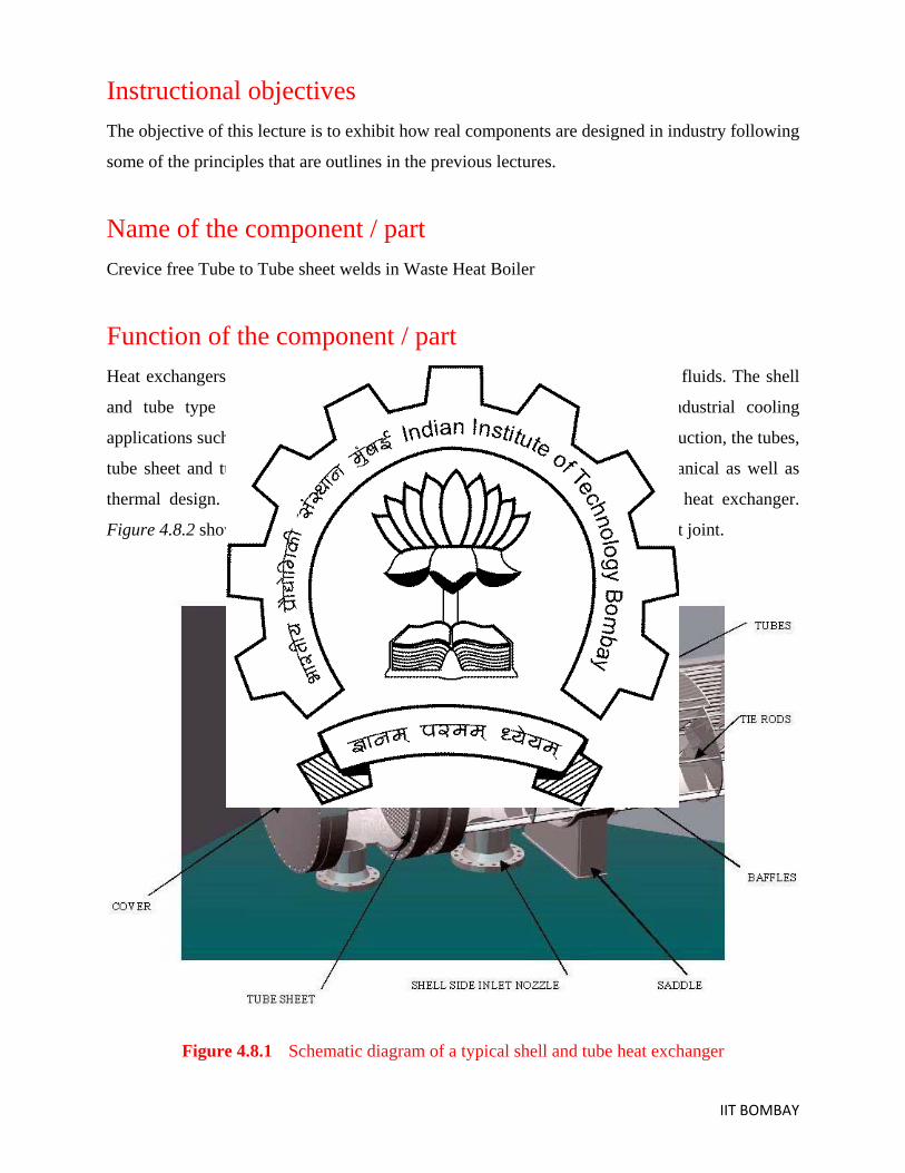
Function of the component / part Heat exchangers are used to facilitate the process of heat transfer between the fluids. The shell
and tube type heat exchangers are the most widely used for various industrial cooling
applications such as in petrochemical and fertilizer plants. In such type of construction, the tubes,
tube sheet and tube-to-tube sheet joints are based on principles of both mechanical as well as
thermal design. Figure 4.8.1 schematically depicts a typical shell and tube heat exchanger.
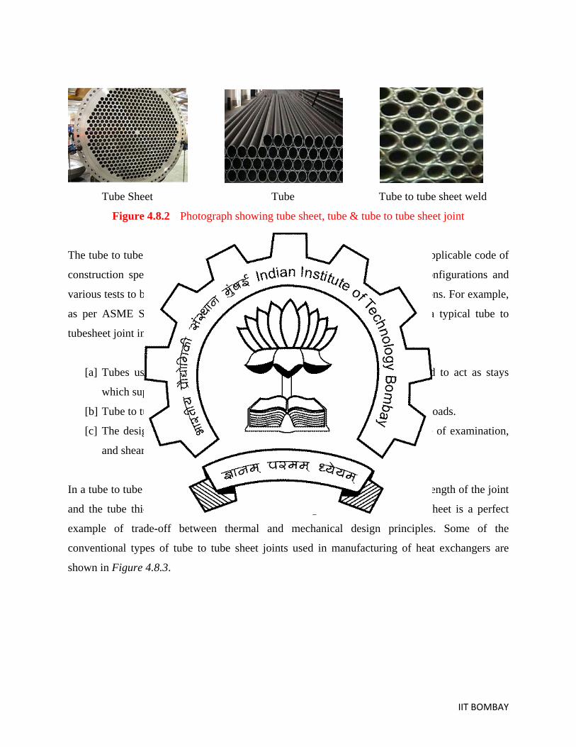
Figure 4.8.2 shows photographs of typical tube sheet, tube and tube to tube sheet joint.
Figure 4.8.1 Schematic diagram of a typical shell and tube heat exchanger
IIT BOMBAY
Tube Sheet Tube Tube to tube sheet weld
Figure 4.8.2 Photograph showing tube sheet, tube & tube to tube sheet joint
The tube to tube sheet joint is the most critical joint in a heat exchanger. The applicable code of
construction specifies some of the standard tube to tube sheet weld joint configurations and
various tests to be performed primarily from the mechanical design considerations. For example,
as per ASME Sec VIII Div-2, following are the design considerations for a typical tube to
tubesheet joint in case of a heat exchanger.
[a] Tubes used in the construction of heat exchangers may be considered to act as stays
which support or contribute to the strength of the tube sheet
[b] Tube to tube sheet joint shall be capable of transferring the applied tube loads.
[c] The design of tube to tube sheet joint depends on type of joint, degree of examination,
and shear load tests, if performed
In a tube to tube sheet joint, mechanical design is usually based on the shear strength of the joint
and the tube thickness is based on the thermal design. Hence, tube to tube sheet is a perfect
example of trade-off between thermal and mechanical design principles. Some of the
conventional types of tube to tube sheet joints used in manufacturing of heat exchangers are
shown in Figure 4.8.3.

IIT BOMBAY
Figure 4.8.3 Conventional tube to tube sheet joint configurations
However, over and above the requirements of standard codes, a number of additions factors
needs to be considered while designing tube-to-tube sheet joint for a specific application
including service conditions, manufacturability, access for inspection, equipment life and
ease of repair.
Service environment Waste heat boiler is a type of heat exchanger used in fertilizer, methanol and hydrogen Plants. In
reformed gas / converter gas boiler, the combinations of high pressure, high temperature and
process gas composition results in higher heat fluxes in the tube inlet. This requires efficient
cooling of the tubes and tube sheet, which is accomplished by keeping the tube sheet wall
thickness as thin as possible. These flexible tube sheet, typically (25 to 30 mm) thick, allows
good cooling by the water on the rear face and lowers the operating temperature. Boilers used in
fertilizer and petrochemical process plants, which have to work at very high operating pressures
require a thicker tube sheet with the thickness ranging from 300 to 500 mm e.g. synthesis loop
boiler in Ammonia plant. With conventional design for the tube to tube sheet joint, high heat flux
at the tube inlet causes evaporation & decomposition of water in the gap between tube & tube
hole resulting in severe crevice corrosion.

IIT BOMBAY
Crevice Corrosion It can be characterized as a localized attack on a metal surface at or immediately adjacent to the
gap or crevice between two joining surfaces. Outside the gap or without the gap, both metals are
resistant to corrosion. The damage is normally confined to one metal at localized area within or
close to the joining surfaces. Crevice corrosion is initiated by a difference in concentration of
some chemical constituents, usually oxygen, which set up an electrochemical concentration cell.
Figure 4.8.4 shows a typical tube to tube sheet joint attacked by crevice corrosion.
Figure 4.8.4 Tube to tube sheet joint attacked by crevice corrosion
On the contrary, providing a full penetration tube to tube sheet weld for this application will
ascertain tube sheet integrity, eliminate the crevice on water side and ensure the stress in the
weld to be same as that of on the tube sheet.
Advantages of Crevice free design Following are considered to be advantages of crevice free joint design.
Full Strength Joints without risk of crevice corrosion
Volumetric Non Destructive Examination Possible
Safest Joint Design (Can Be Used in Critical Service)
Selection of Material Generally “metals” are chosen in the fabrication of Boilers. Tube and tube sheet material used
for manufacturing of boilers should meet the following basic criteria.
Crevice Corrosion

IIT BOMBAY
Resist high temperature H2
Withstand design pressure and temperature,
attack and nitriding,
Provide sufficient ductility for forming operations,
Provide easily weldability,
Allow easy availability at competitive cost
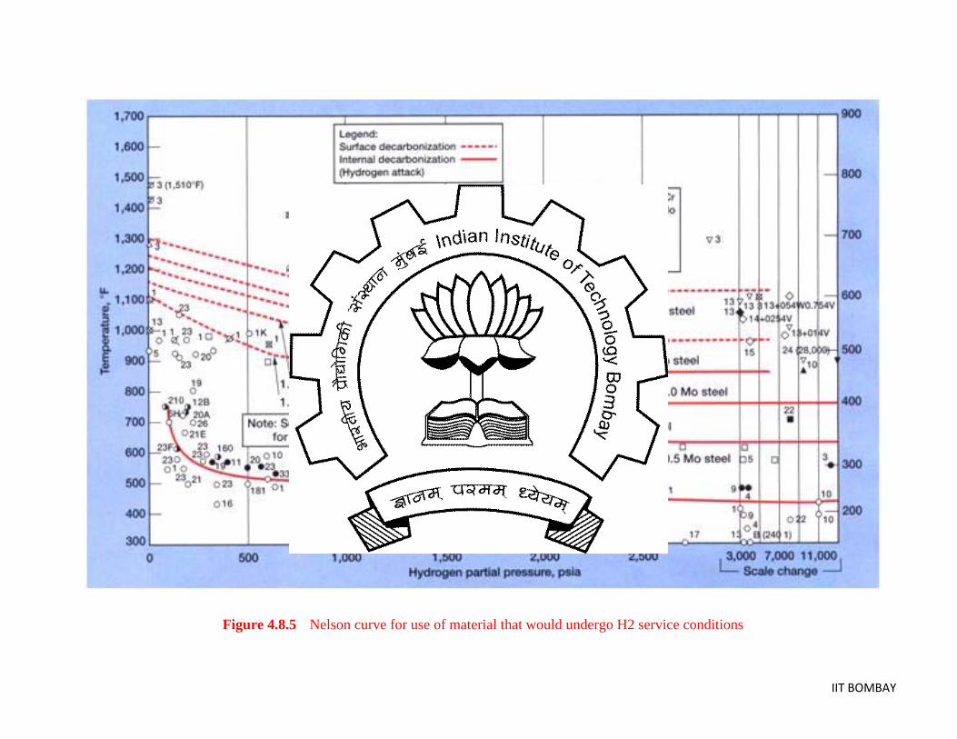
Typically these tube to tube sheet joints should withstand a service condition of 400 to 4500C
temperature and 5 to 300 kg/cm2 (~ 0.5 to 30 MPa) working process. Further, the choice of a
particular metal in hydrogen (H2
) service is based on AP1 941 that is also called the Nelson
Curve [Figure 4.8.5]. Based on Nelson Curve and also considering the basic selection criteria
mentioned above, Cr-Mo steels are the best suited for the given service conditions.
IIT BOMBAY
Figure 4.8.5 Nelson curve for use of material that would undergo H2 service conditions

IIT BOMBAY
Selection of step-wise manufacturing processes Generally there are three different types of crevice free tube to tube sheet joints involved in
manufacturing of waste heat boilers.
Single side full penetration joint (Type-I) The through thickness narrow groove tube to tube sheet joint configuration is as shown in Figure
4.8.6.
Figure 4.8.6 Through thickness full penetration joint
This joint design calls for large-scale development of welding technology. Factors such as
limited access, difficulty of gas shielding, high degree of preheat (1500
Welding performed by manual gas tungsten arc welding process
C minimum) associated
with creep resistant 1 ¼ Cr – ½ Mo steel and protection of weld penetration from oxidation
etc.needs to be considered while selecting a suitable manufacturing (welding) procedure for
producing this joint. Salient features of this type of tube to tube sheet weld is as follows
Full penetration joint welded in 12 to 15 layers
Due to high thickness built –up in layers, joint safety margin is very high
Special GTAW torches are required for welding in narrow and deep groove using long
projection of tungsten electrode.
Large diameter ceramic nozzle with suitably designed gas lens is necessary for effective
argon shielding inside the groove.
Welding filler wire shall match the composition of tube and tube sheet material
In order to account for the distortion, welding is carried out with 2 to 3 passes at a time at
various portions of the tube sheet in a staggered way

IIT BOMBAY
Procedures have been qualified to ASME Code and various customer specifications with
dye penetrant test, radiography examination, macro & micro examination and hardness
survey across the joint.
Highly skilled welders are required for producing this joint.
Lip type joint (Type-II) Here, the weld is produced at the back face of the joint as shown in Figure 4.8.7. Difficulties
addressed for welding of Type-I joint are also applicable here.
Figure 4.8.7 Lip type full penetration joint
Here, unlike the Type-I design; the welding is completed in 2 to 4 passes depending upon the
tube thickness. In the current design, the minimum leak path is very critical because of less
safety margin. With lesser margin of safety, the production of a sound joint with consistent
quality and repeatability is of prime concern for satisfactory operation under severe working
conditions thus necessitating the requirement for automation of these weld joints. Generally
these welds are performed by automatic GTAW process with tube sheet in vertical position.
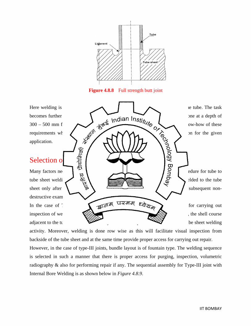
Full Strength Butt Joint (Type-III) In this type of joint design, the joint is welded in single pass without addition of filler wire and
hence the thickness of tube is limited to 4.5 mm. The tube inside diameter ranges from 18 to 30
mm. The typical joint configuration is shown in Figure 4.8.8.
IIT BOMBAY
Figure 4.8.8 Full strength butt joint
Here welding is carried out by Internal Bore Welding technique from ID of the tube. The task
becomes further critical due its non-accessibility since the welding has to be done at a depth of
300 – 500 mm from the Tube sheet face. The designer should have the full know-how of these
requirements which would help him in selecting a suitable joint configuration for the given
application.
Selection of sequential assembly processes Many factors need to be considered while selecting the suitable assembly procedure for tube to
tube sheet welding. For example, in case of Type-1 joints, channel shell is welded to the tube
sheet only after completing welding of all the tube to tube sheet joints and subsequent non-
destructive examinations.
In the case of Type-II joints mentioned earlier, based on the requirements for carrying out
inspection of weld penetration & also to ensure proper purging of the root side, the shell course
adjacent to the tube sheet is welded only after the completion of entire tube to tube sheet welding
activity. Moreover, welding is done row wise as this will facilitate visual inspection from
backside of the tube sheet and at the same time provide proper access for carrying out repair.
However, in the case of type-III joints, bundle layout is of fountain type. The welding sequence
is selected in such a manner that there is proper access for purging, inspection, volumetric
radiography & also for performing repair if any. The sequential assembly for Type-III joint with
Internal Bore Welding is as shown below in Figure 4.8.9.

IIT BOMBAY
Figure 4.8.9 Flow of manufacturing and assembly processes for tube to tube sheet joining
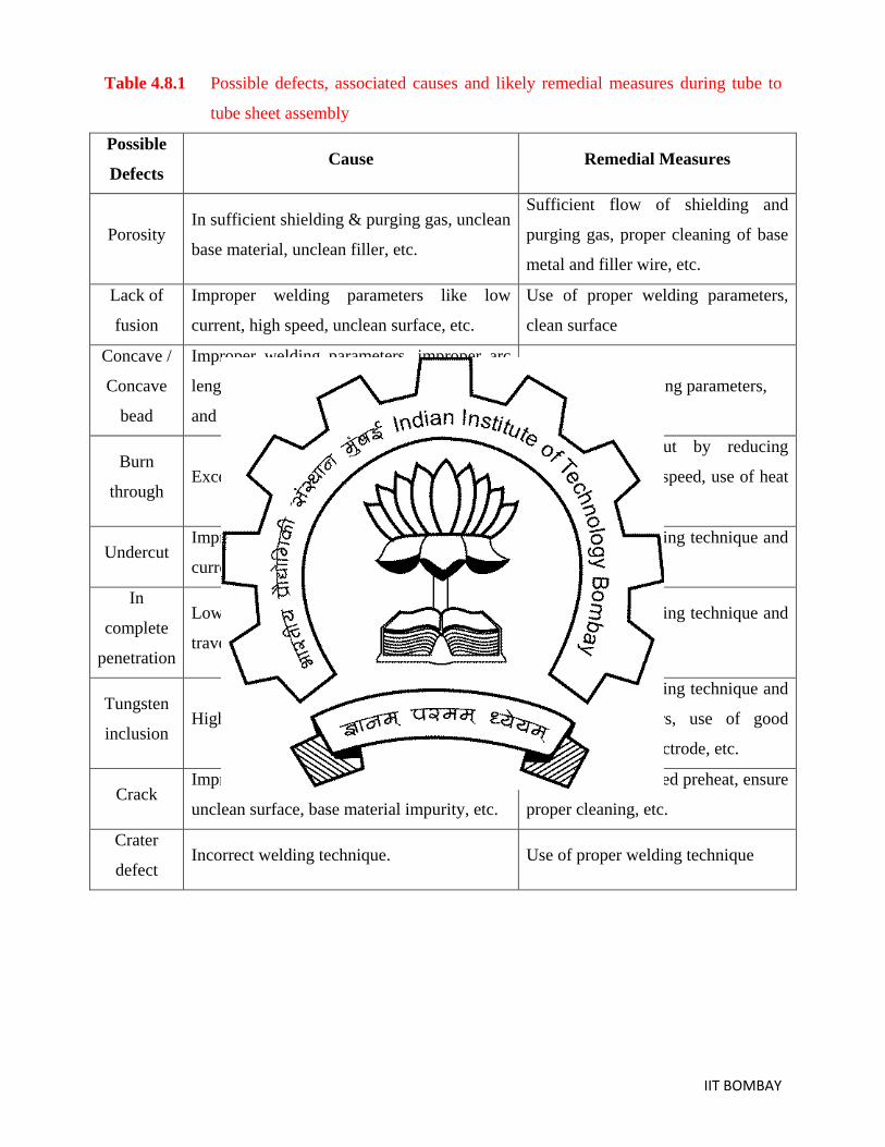
Possible defects and remedial measures Table 4.8.1 lists down the possible defects that can occur during the assembly of tube to tube
sheet joints and the corresponding causes and also remedial measures for the defects.
IIT BOMBAY
Table 4.8.1 Possible defects, associated causes and likely remedial measures during tube to
tube sheet assembly
Possible
Defects Cause Remedial Measures
Porosity In sufficient shielding & purging gas, unclean
base material, unclean filler, etc.
Sufficient flow of shielding and
purging gas, proper cleaning of base
metal and filler wire, etc.
Lack of
fusion
Improper welding parameters like low
current, high speed, unclean surface, etc.
Use of proper welding parameters,
clean surface
Concave /
Concave
bead
Improper welding parameters, improper arc
length, insufficient / excess flow of shielding
and purging gas, etc.
Use of proper welding parameters,
Burn
through Excessive heat input
Reduce heat input by reducing
current, increasing speed, use of heat
sink, etc
Undercut Improper welding parameters like high
current, long arc length, high travel speed, etc
Use of proper welding technique and
welding parameters
In
complete
penetration
Low amperage, tight root opening, high
travel speed, short arc length, etc.
Use of proper welding technique and
welding parameters
Tungsten
inclusion High amperage, poor quality of tungsten
Use of proper welding technique and
welding parameters, use of good
quality tungsten electrode, etc.
Crack Improper preheat temperature, high restraint,
unclean surface, base material impurity, etc.
Follow recommended preheat, ensure
proper cleaning, etc.
Crater
defect Incorrect welding technique. Use of proper welding technique
IIT BOMBAY
Testing/ Inspections methodologies NDE/ Testing during the procedure qualification stage Generally tube to tube sheet welds are qualified as per the code of construction. For example,
following are the steps involved in qualifying a tube to tube sheet welding procedure as per
ASME Sec IX.
Mockup welding Figure 4.8.10 depicts the details of the initial mock-up weld joints that must be produced before
the final assembly is made.
Figure 4.8.10 Suggested mock-up welding practices for tube to tube sheet joining
Visual Examination The mockup weld joints shall be subjected to visual examination as below [Figure 4.8.11].

IIT BOMBAY
Figure 4.8.11 Guidelines for visual inspection of for tube to tube sheet mockup welds
Liquid Penetrant Examination Subsequently, these welds shall be subjected to Liquid Penetrant test and the acceptance criteria
shall be as follows [Figure 4.8.12].
Figure 4.8.12 Acceptance criteria in liquid penetrant examination of tube to tube sheet mockup
welds

IIT BOMBAY
Macro Examination Mockup welds shall be subjected to macro-examination as per details in Figure 4.8.13.
Figure 4.8.13 Guidance of macroexamination of tube to tube sheet mockup welds
However, over and above the code requirements, the mockups are also subjected to various
testing based on the job specification requirements like X-ray radiography and ultrasonic testing,
pull out and tearing testing, crack and flaw examination, etc.
Non destructive testing in production stage Production welding of tube to tube sheet is commenced only upon satisfactory qualification of
the welding procedures and welding operators. Conventional tube to tube sheets are generally
tested by dye penetrant examination after completion of welding. However, following are the
non destructive testing that must be performed on the crevice free joints discussed here.

IIT BOMBAY
Type-I joints are subjected to visual examination, dye penetrant examination, air test and global
hydro-test. The Type-II joints are subjected to visual examination on front and root side of weld,
dye penetrant examination, air test, and global hydro test. The Type-III joints are also subjected
to visual examination on front and root side of weld, dye penetrant examination, radiographic
examination, air test, individual joint helium test, individual joint hydro test and global hydro-
test.
Acknowledgements The help and complete support of Mr. M K Mukherjee and Mr. S. Krishnan from M/s Larsen and
Tubro (Powai, Mumbai, India) are sincerely acknowledged for the preparation of the above case-
study.