module 4
DESCRIPTION
Module 4TRANSCRIPT

AA m e r i c a nm e r i c a n WW e l d i n ge l d i n g S S o c i e t yo c i e t y
Module 4 - Module 4 - 11
Module 4Module 4
Weld Joint Weld Joint GeometryGeometry
------------
Welding and NDE Welding and NDE Symbols Symbols

AA m e r i c a nm e r i c a n WW e l d i n ge l d i n g S S o c i e t yo c i e t y
Module 4 - Module 4 - 22
ANSI/AWS A3.0 - 94ANSI/AWS A3.0 - 94
Standard Welding Terms and Definitions

AA m e r i c a nm e r i c a n WW e l d i n ge l d i n g S S o c i e t yo c i e t y
Module 4 - Module 4 - 33
Introduction - 1 of 2Introduction - 1 of 2 The geometry of joints and welds The geometry of joints and welds
must be clearly stated and understood must be clearly stated and understood by all parties involved with fabricationby all parties involved with fabrication
Terminology used per A3.0 and A2.4Terminology used per A3.0 and A2.4 Don’t use slang termsDon’t use slang terms Welding symbols are a shorthand Welding symbols are a shorthand
method for clearly stating exactly method for clearly stating exactly what welding is to be done and wherewhat welding is to be done and where

AA m e r i c a nm e r i c a n WW e l d i n ge l d i n g S S o c i e t yo c i e t y
Module 4 - Module 4 - 44
Introduction - 2 of 2Introduction - 2 of 2
Joint and Weld geometry per A3.0-Joint and Weld geometry per A3.0-9494
Classroom discussion on A3.0Classroom discussion on A3.0 Welding Symbols per A2.4-98Welding Symbols per A2.4-98 Classroom discussion on A2.4-98Classroom discussion on A2.4-98 WIT Module 4 - additional Study WIT Module 4 - additional Study
GuideGuide

AA m e r i c a nm e r i c a n WW e l d i n ge l d i n g S S o c i e t yo c i e t y
Module 4 - Module 4 - 55Weld or Joint Geometry & Weld or Joint Geometry & TermsTerms
Imperative to know the difference Imperative to know the difference between a ‘joint’ and a ‘weld’ and between a ‘joint’ and a ‘weld’ and use terms properlyuse terms properly
Standard terms must be used when Standard terms must be used when dealing with weld joint and weld dealing with weld joint and weld geometry to avoid errors in geometry to avoid errors in communicationcommunication

AA m e r i c a nm e r i c a n WW e l d i n ge l d i n g S S o c i e t yo c i e t y
Module 4 - Module 4 - 66
5 Basic Joint Types5 Basic Joint Types
Refer to A3.0-94, Fig 1, page 41Refer to A3.0-94, Fig 1, page 41
ButtButt CornerCorner T-JointT-Joint LapLap EdgeEdge

AA m e r i c a nm e r i c a n WW e l d i n ge l d i n g S S o c i e t yo c i e t y
Module 4 - Module 4 - 77
Butt JointButt Joint
A Joint between A Joint between 2 members 2 members aligned aligned approximately approximately in the same in the same planeplane

AA m e r i c a nm e r i c a n WW e l d i n ge l d i n g S S o c i e t yo c i e t y
Module 4 - Module 4 - 88Butt Joint - Applicable Butt Joint - Applicable WeldsWelds
Bevel-grooveBevel-groove Flare-bevel-Flare-bevel-
groovegroove Flare-v-grooveFlare-v-groove J-grooveJ-groove Square-grooveSquare-groove
U-grooveU-groove V-grooveV-groove Edge-flangeEdge-flange BrazeBraze

AA m e r i c a nm e r i c a n WW e l d i n ge l d i n g S S o c i e t yo c i e t y
Module 4 - Module 4 - 99
Corner JointCorner Joint
A Joint between 2 A Joint between 2 members located members located approximately at approximately at right angles to right angles to each othereach other inin the the form of an Lform of an L

AA m e r i c a nm e r i c a n WW e l d i n ge l d i n g S S o c i e t yo c i e t y
Module 4 - Module 4 - 1010Corner Joint - Applicable Corner Joint - Applicable WeldsWelds
FilletFillet Bevel-grooveBevel-groove Flare-bevel-grooveFlare-bevel-groove Flare-v-grooveFlare-v-groove J-grooveJ-groove Square-grooveSquare-groove U-grooveU-groove
V-grooveV-groove PlugPlug SlotSlot SpotSpot SeamSeam ProjectionProjection BrazeBraze

AA m e r i c a nm e r i c a n WW e l d i n ge l d i n g S S o c i e t yo c i e t y
Module 4 - Module 4 - 1111
T-JointT-Joint
A Joint between 2 A Joint between 2 members located members located at approximately at approximately right angles to right angles to each other in the each other in the form of a Tform of a T

AA m e r i c a nm e r i c a n WW e l d i n ge l d i n g S S o c i e t yo c i e t y
Module 4 - Module 4 - 1212
T Joint - Applicable WeldsT Joint - Applicable Welds
FilletFillet Bevel-grooveBevel-groove Flare-bevel-Flare-bevel-
groovegroove J-grooveJ-groove Square-grooveSquare-groove PlugPlug
SlotSlot SpotSpot SeamSeam ProjectionProjection BrazeBraze

AA m e r i c a nm e r i c a n WW e l d i n ge l d i n g S S o c i e t yo c i e t y
Module 4 - Module 4 - 1313
Lap JointLap Joint
A Joint between 2 A Joint between 2 overlapping overlapping members in members in parallel planesparallel planes

AA m e r i c a nm e r i c a n WW e l d i n ge l d i n g S S o c i e t yo c i e t y
Module 4 - Module 4 - 1414Lap Joint - Applicable Lap Joint - Applicable WeldsWelds
FilletFillet Bevel-grooveBevel-groove Flare-bevel-Flare-bevel-
groovegroove J-grooveJ-groove PlugPlug
SlotSlot SpotSpot SeamSeam ProjectionProjection BrazeBraze

AA m e r i c a nm e r i c a n WW e l d i n ge l d i n g S S o c i e t yo c i e t y
Module 4 - Module 4 - 1515
Edge JointEdge Joint
A Joint between A Joint between the edges of 2 or the edges of 2 or more parallel, or more parallel, or nearly parallel, nearly parallel, membersmembers

AA m e r i c a nm e r i c a n WW e l d i n ge l d i n g S S o c i e t yo c i e t y
Module 4 - Module 4 - 1616Edge Joint - Applicable Edge Joint - Applicable WeldsWelds
Bevel-grooveBevel-groove Flare-bevel-Flare-bevel-
groovegroove Flare-v-grooveFlare-v-groove J-grooveJ-groove Square-grooveSquare-groove
U-grooveU-groove V-grooveV-groove EdgeEdge SeamSeam

AA m e r i c a nm e r i c a n WW e l d i n ge l d i n g S S o c i e t yo c i e t y
Module 4 - Module 4 - 1717
Refer to A3.0-94, Figs 4, 5, 6, 7, pages 44 - 47
Joint NomenclatureJoint Nomenclature
Joint rootJoint root Groove faceGroove face Root edgeRoot edge Root faceRoot face Bevel angleBevel angle Depth of bevelDepth of bevel Groove angleGroove angle
Groove radiusGroove radius Root openingRoot opening Edge shapesEdge shapes
– square– single or double bevel– single or double J– round

AA m e r i c a nm e r i c a n WW e l d i n ge l d i n g S S o c i e t yo c i e t y
Module 4 - Module 4 - 1818
Figure 4 -
Joint Root

AA m e r i c a nm e r i c a n WW e l d i n ge l d i n g S S o c i e t yo c i e t y
Module 4 - Module 4 - 1919
Figure 5 -
Groove Face
Root Edge
Root Face

AA m e r i c a nm e r i c a n WW e l d i n ge l d i n g S S o c i e t yo c i e t y
Module 4 - Module 4 - 2020
Figure 6 -
Bevel Angle
Bevel Depth
Groove Angle
Groove Radius
Root Opening

AA m e r i c a nm e r i c a n WW e l d i n ge l d i n g S S o c i e t yo c i e t y
Module 4 - Module 4 - 2121
Figure 7 - Figure 7 - Edge ShapesEdge Shapes
SquareSquare Single BevelSingle Bevel Double BevelDouble Bevel Single JSingle J Double JDouble J FlangeFlange RoundRound

AA m e r i c a nm e r i c a n WW e l d i n ge l d i n g S S o c i e t yo c i e t y
Module 4 - Module 4 - 2222Joint Geometry - Key Joint Geometry - Key LearningsLearnings
Refer to A3.0-94, Figures 4, 5, 6, pages 44 - Refer to A3.0-94, Figures 4, 5, 6, pages 44 - 4646
A joint root can be linear in nature, or an A joint root can be linear in nature, or an areaarea
A surface can be both a Root face & a A surface can be both a Root face & a Groove faceGroove face
An angle can be both a Bevel angle and a An angle can be both a Bevel angle and a Groove angleGroove angle

AA m e r i c a nm e r i c a n WW e l d i n ge l d i n g S S o c i e t yo c i e t y
Module 4 - Module 4 - 2323
Weld JointsWeld Joints
Refer to A3.0-94, Figs 8, 9, 10, 14, 15Refer to A3.0-94, Figs 8, 9, 10, 14, 15
Single groove - Single groove - p 48p 48 Double-groove - Double-groove - p 49p 49 Flanged Joints - Flanged Joints - p 50p 50 Seam and Spot - Seam and Spot - p 53p 53 Various - p 54Various - p 54

AA m e r i c a nm e r i c a n WW e l d i n ge l d i n g S S o c i e t yo c i e t y
Module 4 - Module 4 - 2424Figure 8 -Figure 8 -Single Groove Single Groove
WeldsWelds
Single SquareSingle Square Single BevelSingle Bevel Single VSingle V Single JSingle J Single USingle U Single Flare BevelSingle Flare Bevel Single Flare VSingle Flare V

AA m e r i c a nm e r i c a n WW e l d i n ge l d i n g S S o c i e t yo c i e t y
Module 4 - Module 4 - 2525Figure 8 -Figure 8 -Single Groove Single Groove
WeldsWelds
Double SquareDouble Square Double BevelDouble Bevel Double VDouble V Double JDouble J Double UDouble U Double Flare BevelDouble Flare Bevel Double Flare VDouble Flare V

AA m e r i c a nm e r i c a n WW e l d i n ge l d i n g S S o c i e t yo c i e t y
Module 4 - Module 4 - 2626
Figure 10 - Figure 10 - Flanged WeldsFlanged Welds
Edge - Flanged ButtEdge - Flanged Butt Edge - Melt ThroughEdge - Melt Through Edge - Flanged CornerEdge - Flanged Corner Square, Flare VSquare, Flare V RSW in Flanged CornerRSW in Flanged Corner Fillet, Flare-Bevel in TFillet, Flare-Bevel in T

AA m e r i c a nm e r i c a n WW e l d i n ge l d i n g S S o c i e t yo c i e t y
Module 4 - Module 4 - 2727Figure 14 -Figure 14 -Seam, Spot Seam, Spot
WeldsWelds
Arc Seam WeldArc Seam Weld EB Seam WeldEB Seam Weld RSW Seam WeldRSW Seam Weld RSW Spot WeldsRSW Spot Welds Arc Spot WeldsArc Spot Welds

AA m e r i c a nm e r i c a n WW e l d i n ge l d i n g S S o c i e t yo c i e t y
Module 4 - Module 4 - 2828
Figure 15 - Figure 15 - Various WeldsVarious Welds
Upset WeldUpset Weld Flash WeldFlash Weld Surfacing WeldSurfacing Weld Slot WeldsSlot Welds Plug WeldsPlug Welds Fillet WeldsFillet Welds

AA m e r i c a nm e r i c a n WW e l d i n ge l d i n g S S o c i e t yo c i e t y
Module 4 - Module 4 - 2929
Welding PositionWelding Position
Refer to A3.0-94, Figs 16 - 21, pages 55 - 64Refer to A3.0-94, Figs 16 - 21, pages 55 - 64
Review position diagrams & tables for groove Review position diagrams & tables for groove and fillet welds in plate and pipe - pages 55-57and fillet welds in plate and pipe - pages 55-57
Review welding test positions for groove and Review welding test positions for groove and fillet welds on plate and pipe - pages 58-63fillet welds on plate and pipe - pages 58-63
Note error in Fig 19D, page 61Note error in Fig 19D, page 61 Review Torch Position in Fig 21, page 64Review Torch Position in Fig 21, page 64

AA m e r i c a nm e r i c a n WW e l d i n ge l d i n g S S o c i e t yo c i e t y
Module 4 - Module 4 - 3030
Welding Beads, SequencesWelding Beads, Sequences
Stringer beadStringer bead Weave beadWeave bead Backstep Backstep
sequencesequence
Block sequenceBlock sequence Cascade Cascade
sequencesequence Layers vs beadsLayers vs beads
Refer to A3.0-94, Figs 22 -23, pages 65 - 67

AA m e r i c a nm e r i c a n WW e l d i n ge l d i n g S S o c i e t yo c i e t y
Module 4 - Module 4 - 3131
Parts Of A WeldParts Of A Weld
ToeToe FaceFace Face reinforcementFace reinforcement Root reinforcementRoot reinforcement Root surfaceRoot surface Weld RootWeld Root
BeadBead Back weldBack weld Backing weldBacking weld SpacerSpacer Heat-Affected Heat-Affected
Zone (HAZ)Zone (HAZ)
Refer to A3.0-94, Fig 24, pages 68 - 70

AA m e r i c a nm e r i c a n WW e l d i n ge l d i n g S S o c i e t yo c i e t y
Module 4 - Module 4 - 3232
Figure 24 - Figure 24 - Parts of WeldsParts of Welds
Weld FaceWeld Face Weld ToeWeld Toe Face ReinforcementFace Reinforcement Root ReinforcementRoot Reinforcement Weld RootWeld Root Back WeldBack Weld Backing WeldBacking Weld

AA m e r i c a nm e r i c a n WW e l d i n ge l d i n g S S o c i e t yo c i e t y
Module 4 - Module 4 - 3333
Figure 24 - Figure 24 - Parts of WeldsParts of Welds
Weld RootWeld Root Leg, Face, ToeLeg, Face, Toe SpacerSpacer Weld MetalWeld Metal Heat Affected Heat Affected
ZoneZone

AA m e r i c a nm e r i c a n WW e l d i n ge l d i n g S S o c i e t yo c i e t y
Module 4 - Module 4 - 3434
Figure 24 - Figure 24 - Parts of WeldsParts of Welds
Weld RootWeld Root Weld BeadWeld Bead Dilution PercentDilution Percent

AA m e r i c a nm e r i c a n WW e l d i n ge l d i n g S S o c i e t yo c i e t y
Module 4 - Module 4 - 3535
Refer to A3.0, Fig 25, pages 71 - 72
Weld Sizes & TermsWeld Sizes & Terms
Convex FilletConvex Fillet Leg, size equalLeg, size equal ConvexityConvexity Actual throatActual throat Effective throatEffective throat Theoretical throatTheoretical throat
Concave Fillet Concave Fillet LegLeg Size (less than leg Size (less than leg
length)length) ConcavityConcavity Actual, Effective Actual, Effective
throats equalthroats equal Theoretical throatTheoretical throat

AA m e r i c a nm e r i c a n WW e l d i n ge l d i n g S S o c i e t yo c i e t y
Module 4 - Module 4 - 3636
Convex Fillet WeldConvex Fillet Weld

AA m e r i c a nm e r i c a n WW e l d i n ge l d i n g S S o c i e t yo c i e t y
Module 4 - Module 4 - 3737
Concave Fillet WeldConcave Fillet Weld

AA m e r i c a nm e r i c a n WW e l d i n ge l d i n g S S o c i e t yo c i e t y
Module 4 - Module 4 - 3838
Joint & Root PenetrationJoint & Root Penetration
Note Incomplete Joint Penetration dimension

AA m e r i c a nm e r i c a n WW e l d i n ge l d i n g S S o c i e t yo c i e t y
Module 4 - Module 4 - 3939Incomplete Joint Incomplete Joint PenetrationPenetration
Refer to A3.0, Fig 26 pages 75 - 76Refer to A3.0, Fig 26 pages 75 - 76
Term used only in reference to Term used only in reference to groove weldsgroove welds
If only Partial Penetration is If only Partial Penetration is intended, it is incorrect to refer to intended, it is incorrect to refer to the weld as Incomplete Joint the weld as Incomplete Joint PenetrationPenetration

AA m e r i c a nm e r i c a n WW e l d i n ge l d i n g S S o c i e t yo c i e t y
Module 4 - Module 4 - 4040Incomplete Joint Incomplete Joint
PenetrationPenetration
(Or Partial Joint Penetration if intended)
E total can never be > base metal thickness

AA m e r i c a nm e r i c a n WW e l d i n ge l d i n g S S o c i e t yo c i e t y
Module 4 - Module 4 - 4141Incomplete Joint Penetration Incomplete Joint Penetration
ErrorError
Fig 26 (c) - page 75 - Incomplete Joint Penetration reference dimension is in error on sketch
Error !
Correct Dimension

AA m e r i c a nm e r i c a n WW e l d i n ge l d i n g S S o c i e t yo c i e t y
Module 4 - Module 4 - 4242Melt-through, Root Melt-through, Root SurfacesSurfaces
Refer to A3.0-94, Fig 27, page 77 Refer to A3.0-94, Fig 27, page 77
Melt-throughMelt-through Convex root surfaceConvex root surface Concave root surfaceConcave root surface
– Slang term is ‘suck back’ - Don’t Use

AA m e r i c a nm e r i c a n WW e l d i n ge l d i n g S S o c i e t yo c i e t y
Module 4 - Module 4 - 4343
Incomplete FusionIncomplete Fusion
Refer to A3.0-94, Fig 29, page 79Refer to A3.0-94, Fig 29, page 79
Used in reference to both groove Used in reference to both groove and fillet weldsand fillet welds
Slang term often misused is ‘cold Slang term often misused is ‘cold lap’lap’

AA m e r i c a nm e r i c a n WW e l d i n ge l d i n g S S o c i e t yo c i e t y
Module 4 - Module 4 - 4444
Incomplete Fusion - 1 of 2Incomplete Fusion - 1 of 2

AA m e r i c a nm e r i c a n WW e l d i n ge l d i n g S S o c i e t yo c i e t y
Module 4 - Module 4 - 4545
Incomplete Fusion - 2 of 2Incomplete Fusion - 2 of 2

AA m e r i c a nm e r i c a n WW e l d i n ge l d i n g S S o c i e t yo c i e t y
Module 4 - Module 4 - 4646
Fusion Weld TermsFusion Weld TermsRefer to A3.0, Figure 30, page 80

AA m e r i c a nm e r i c a n WW e l d i n ge l d i n g S S o c i e t yo c i e t y
Module 4 - Module 4 - 4747
Weld DiscontinuitiesWeld Discontinuities
Refer to A3.0-94, Fig 32, 33, pages Refer to A3.0-94, Fig 32, 33, pages 82 - 8382 - 83
Cracks - see nomenclature in Fig 33Cracks - see nomenclature in Fig 33 UndercutUndercut OverlapOverlap UnderfillUnderfill

AA m e r i c a nm e r i c a n WW e l d i n ge l d i n g S S o c i e t yo c i e t y
Module 4 - Module 4 - 4848
ANSI/AWS A2.4-98ANSI/AWS A2.4-98
Standard Symbols for Welding, Brazing, and Nondestructive Examination

AA m e r i c a nm e r i c a n WW e l d i n ge l d i n g S S o c i e t yo c i e t y
Module 4 - Module 4 - 4949Welding Symbols - Welding Symbols - IntroductionIntroduction
Refer to A2.4-98Refer to A2.4-98
A shorthand method of conveying A shorthand method of conveying welding informationwelding information
AWS system used all over the worldAWS system used all over the world Modified as necessary to reflect needs Modified as necessary to reflect needs
of industriesof industries Very simple, but a very powerful Very simple, but a very powerful
system for conveying informationsystem for conveying information

AA m e r i c a nm e r i c a n WW e l d i n ge l d i n g S S o c i e t yo c i e t y
Module 4 - Module 4 - 5050Weld Symbol vs Welding Weld Symbol vs Welding SymbolSymbol
A A Weld SymbolWeld Symbol indicates the type of indicates the type of Weld, and may be a part of the:Weld, and may be a part of the:
Welding SymbolWelding Symbol - the complete - the complete information needed to convey the information needed to convey the necessary welding information to necessary welding information to all parties, including the welder. It all parties, including the welder. It contains several contains several elementselements, , including the Weld Symbol.including the Weld Symbol.

AA m e r i c a nm e r i c a n WW e l d i n ge l d i n g S S o c i e t yo c i e t y
Module 4 - Module 4 - 5151
Weld SymbolsWeld Symbols

AA m e r i c a nm e r i c a n WW e l d i n ge l d i n g S S o c i e t yo c i e t y
Module 4 - Module 4 - 5252
The above welds may be applied to one side or both sides of the joint, or in combination.
Groove Weld Types - 8Groove Weld Types - 8
SquareSquare ScarfScarf VV BevelBevel
UU JJ Flare-VFlare-V Flare-bevelFlare-bevel

AA m e r i c a nm e r i c a n WW e l d i n ge l d i n g S S o c i e t yo c i e t y
Module 4 - Module 4 - 5353
* Stud and surfacing symbols are always placed below reference line.
Other Weld Types - 11Other Weld Types - 11
FilletFillet Plug or SlotPlug or Slot Stud *Stud * Spot or Spot or
ProjectionProjection
SeamSeam Back or BackingBack or Backing Surfacing *Surfacing * EdgeEdge

AA m e r i c a nm e r i c a n WW e l d i n ge l d i n g S S o c i e t yo c i e t y
Module 4 - Module 4 - 5454
Weld Symbols - RulesWeld Symbols - Rules
Symbols with a perpendicular leg Symbols with a perpendicular leg shall have the perpendicular leg shall have the perpendicular leg drawn on the left side of the symbol. drawn on the left side of the symbol. (fillet, bevel-groove, J-groove, and (fillet, bevel-groove, J-groove, and flare-bevel-groove)flare-bevel-groove)
The symbols for Stud and Surfacing The symbols for Stud and Surfacing welds shall always be drawn welds shall always be drawn belowbelow the reference line.the reference line.

AA m e r i c a nm e r i c a n WW e l d i n ge l d i n g S S o c i e t yo c i e t y
Module 4 - Module 4 - 5555
Welding SymbolWelding Symbol

AA m e r i c a nm e r i c a n WW e l d i n ge l d i n g S S o c i e t yo c i e t y
Module 4 - Module 4 - 5656Supplementary Supplementary SymbolsSymbols

AA m e r i c a nm e r i c a n WW e l d i n ge l d i n g S S o c i e t yo c i e t y
Module 4 - Module 4 - 5757Elements of Welding Elements of Welding SymbolsSymbols
Required Required ElementsElements
Reference Line - Reference Line - always horizontalalways horizontal
ArrowArrow
Optional ElementsOptional Elements Multiple reference linesMultiple reference lines TailTail Weld SymbolWeld Symbol DimensionsDimensions Supplementary SymbolsSupplementary Symbols FinishFinish Specification, ProcessSpecification, Process

AA m e r i c a nm e r i c a n WW e l d i n ge l d i n g S S o c i e t yo c i e t y
Module 4 - Module 4 - 5858
Arrow NotationArrow Notation
Information applicable Information applicable to the arrow side of to the arrow side of the joint is placed the joint is placed below the reference below the reference lineline
Information applicable Information applicable to the other side of a to the other side of a joint is placed above joint is placed above the reference linethe reference line

AA m e r i c a nm e r i c a n WW e l d i n ge l d i n g S S o c i e t yo c i e t y
Module 4 - Module 4 - 5959
Arrow Side Weld SymbolsArrow Side Weld Symbols

AA m e r i c a nm e r i c a n WW e l d i n ge l d i n g S S o c i e t yo c i e t y
Module 4 - Module 4 - 6060
Other Side Weld SymbolsOther Side Weld Symbols

AA m e r i c a nm e r i c a n WW e l d i n ge l d i n g S S o c i e t yo c i e t y
Module 4 - Module 4 - 6161
Side SignificanceSide Significance
The Weld Symbol The Weld Symbol straddles the straddles the reference line when reference line when there is no side there is no side SignificanceSignificance
Resistance Spot WeldResistance Spot Weld
Resistance Seam WeldResistance Seam Weld
Flash WeldFlash Weld

AA m e r i c a nm e r i c a n WW e l d i n ge l d i n g S S o c i e t yo c i e t y
Module 4 - Module 4 - 6262
Break in Arrow LineBreak in Arrow Line
A break in the A break in the arrow line signifies arrow line signifies that the member that the member the arrow points to the arrow points to is the member is the member receiving the edge receiving the edge preparation.preparation.

AA m e r i c a nm e r i c a n WW e l d i n ge l d i n g S S o c i e t yo c i e t y
Module 4 - Module 4 - 6363
Combined Weld SymbolsCombined Weld Symbols
For joints For joints requiring more requiring more than one weld than one weld type, a weld type, a weld symbol shall be symbol shall be used to specify used to specify each weldeach weld

AA m e r i c a nm e r i c a n WW e l d i n ge l d i n g S S o c i e t yo c i e t y
Module 4 - Module 4 - 6464
Multiple ArrowsMultiple Arrows
Two or more Two or more arrows may be arrows may be used for a single used for a single reference line to reference line to denote locations denote locations where identical where identical welds are welds are specified.specified.

AA m e r i c a nm e r i c a n WW e l d i n ge l d i n g S S o c i e t yo c i e t y
Module 4 - Module 4 - 6565
Multiple Reference LinesMultiple Reference Lines Two or more Two or more
reference lines may reference lines may be used to indicate be used to indicate a sequence of a sequence of operations. operations.
The first operation The first operation is always on the is always on the reference line reference line nearest the arrow.nearest the arrow.

AA m e r i c a nm e r i c a n WW e l d i n ge l d i n g S S o c i e t yo c i e t y
Module 4 - Module 4 - 6666Field Weld & Weld All-Field Weld & Weld All-AroundAround
The Field Weld symbol The Field Weld symbol is a solid flag, and is is a solid flag, and is always located at always located at junction of the arrow junction of the arrow and reference line.and reference line.
The Weld All-Around The Weld All-Around symbol is a circle and symbol is a circle and is located at junction is located at junction of the arrow and of the arrow and reference line.reference line.

AA m e r i c a nm e r i c a n WW e l d i n ge l d i n g S S o c i e t yo c i e t y
Module 4 - Module 4 - 6767
TailTail
The Tail is used to The Tail is used to specify welding specify welding process process information or information or other such other such information information needed to convey needed to convey the necessary the necessary welding details.welding details.

AA m e r i c a nm e r i c a n WW e l d i n ge l d i n g S S o c i e t yo c i e t y
Module 4 - Module 4 - 6868
Welding and NDE SymbolsWelding and NDE Symbols Welding and NDE symbols Welding and NDE symbols
can be combined on the can be combined on the same reference line, or on same reference line, or on separate multiple reference separate multiple reference lines.lines.
Combining welding and NDE Combining welding and NDE symbols on multiple symbols on multiple reference lines often clarifies reference lines often clarifies the exact sequence of the exact sequence of operations required.operations required.

AA m e r i c a nm e r i c a n WW e l d i n ge l d i n g S S o c i e t yo c i e t y
Module 4 - Module 4 - 6969
Weld Contours & FinishingWeld Contours & Finishing Weld surfaces can be Weld surfaces can be
contoured to several contoured to several shapes; convex, concave, shapes; convex, concave, flush, or flat.flush, or flat.
Finishing methods are Finishing methods are abbreviated as shown.abbreviated as shown.
‘‘U’ denotes contour U’ denotes contour method is ‘Unspecified’method is ‘Unspecified’
Contour symbol w/o finish Contour symbol w/o finish symbol means as-weldedsymbol means as-welded

AA m e r i c a nm e r i c a n WW e l d i n ge l d i n g S S o c i e t yo c i e t y
Module 4 - Module 4 - 7070
Symbol Dimensions?Symbol Dimensions? Tolerances, if required, are to be placed in tailTolerances, if required, are to be placed in tail Welding Symbols are usually drawn without Welding Symbols are usually drawn without
dimension units such as inches or millimeters.dimension units such as inches or millimeters. But, Welding Symbols to be used for But, Welding Symbols to be used for
publications or those requiring high precision publications or those requiring high precision should be dimensioned and have the should be dimensioned and have the dimensional tolerances noted within the tail.dimensional tolerances noted within the tail.

AA m e r i c a nm e r i c a n WW e l d i n ge l d i n g S S o c i e t yo c i e t y
Module 4 - Module 4 - 7171Symbol ExamplesSymbol Examples
Arrow side - V- grooveArrow side - V- groove
Other side - V- grooveOther side - V- groove
Both sides - V- grooveBoth sides - V- groove

AA m e r i c a nm e r i c a n WW e l d i n ge l d i n g S S o c i e t yo c i e t y
Module 4 - Module 4 - 7272
Symbol ExamplesSymbol Examples
Back or Backing, Back or Backing, single J-groove, single J-groove, filletfillet
Single-bevel-Single-bevel-groove, double groove, double filletfillet

AA m e r i c a nm e r i c a n WW e l d i n ge l d i n g S S o c i e t yo c i e t y
Module 4 - Module 4 - 7373
Symbol ExamplesSymbol Examples Weld all-Weld all-
around around symbol is a symbol is a very useful very useful symbolsymbol
Multi-plane weld Multi-plane weld requirements are very requirements are very simple to sketch using simple to sketch using symbolsymbol

AA m e r i c a nm e r i c a n WW e l d i n ge l d i n g S S o c i e t yo c i e t y
Module 4 - Module 4 - 7474
Symbol ExamplesSymbol Examples Square-groove butt Square-groove butt
with melt-throughwith melt-through
Edge weld on Edge weld on flanged butt with flanged butt with melt-throughmelt-through
Edge weld on Edge weld on flanged corner joint flanged corner joint with melt-throughwith melt-through

AA m e r i c a nm e r i c a n WW e l d i n ge l d i n g S S o c i e t yo c i e t y
Module 4 - Module 4 - 7575Groove Weld Dimensions - 1 Groove Weld Dimensions - 1 of 9of 9
Depth of Bevel, S, and Depth of Bevel, S, and Size of Weld, (E) Size of Weld, (E) placed to the left of the placed to the left of the symbolsymbol
1/4 inch bevel with a 1/4 inch bevel with a 3/8 inch weld3/8 inch weld
(No dimensions means (No dimensions means complete penetration)complete penetration)

AA m e r i c a nm e r i c a n WW e l d i n ge l d i n g S S o c i e t yo c i e t y
Module 4 - Module 4 - 7676Groove Weld Dimensions - Groove Weld Dimensions - 2 of 92 of 9
Refer to A2.4, Fig 15, pg Refer to A2.4, Fig 15, pg 3131
Examples of Groove Weld Examples of Groove Weld Bevel & Weld Dimensions Bevel & Weld Dimensions
No dimensions means No dimensions means complete penetrationcomplete penetration

AA m e r i c a nm e r i c a n WW e l d i n ge l d i n g S S o c i e t yo c i e t y
Module 4 - Module 4 - 7777Groove Weld Dimensions - Groove Weld Dimensions - 3 of 93 of 9
The Root Opening The Root Opening is placed within the is placed within the weld symbol or just weld symbol or just outside, and only outside, and only on one side of the on one side of the reference linereference line
Inches or mm per Inches or mm per shop practiceshop practice

AA m e r i c a nm e r i c a n WW e l d i n ge l d i n g S S o c i e t yo c i e t y
Module 4 - Module 4 - 7878Groove Weld Dimensions - Groove Weld Dimensions - 4 of 94 of 9
Groove Angle is Groove Angle is placed just placed just outside the outside the weld symbolweld symbol

AA m e r i c a nm e r i c a n WW e l d i n ge l d i n g S S o c i e t yo c i e t y
Module 4 - Module 4 - 7979Groove Weld Dimensions - Groove Weld Dimensions - 5 of 9 5 of 9
The length of the weld shall be placed to the The length of the weld shall be placed to the right of the weld symbol. No dimension required right of the weld symbol. No dimension required if weld is continuous for full length of joint.if weld is continuous for full length of joint.

AA m e r i c a nm e r i c a n WW e l d i n ge l d i n g S S o c i e t yo c i e t y
Module 4 - Module 4 - 8080Groove Weld Dimensions - Groove Weld Dimensions - 6 of 96 of 9
Pitch is the distance between centers of adjacent Pitch is the distance between centers of adjacent weld segments. Pitch length is shown to the weld segments. Pitch length is shown to the right of the weld length dimension following a right of the weld length dimension following a hyphen.hyphen.

AA m e r i c a nm e r i c a n WW e l d i n ge l d i n g S S o c i e t yo c i e t y
Module 4 - Module 4 - 8181Groove Weld Dimensions - Groove Weld Dimensions - 7 of 97 of 9
Chain intermittent weld dimensions are Chain intermittent weld dimensions are to be placed on both sides of reference to be placed on both sides of reference line, and opposite each otherline, and opposite each other

AA m e r i c a nm e r i c a n WW e l d i n ge l d i n g S S o c i e t yo c i e t y
Module 4 - Module 4 - 8282Groove Weld Dimensions - Groove Weld Dimensions - 8 of 98 of 9
Staggered intermittent weld dimensions Staggered intermittent weld dimensions are to be placed on both sides of reference are to be placed on both sides of reference line, and offset from each other.line, and offset from each other.

AA m e r i c a nm e r i c a n WW e l d i n ge l d i n g S S o c i e t yo c i e t y
Module 4 - Module 4 - 8383Groove Weld Dimensions - Groove Weld Dimensions - 9 of 99 of 9
Refer to Refer to A2.4, Fig A2.4, Fig 30, pages 30, pages 36, 3736, 37
Flare-Bevel Flare-Bevel & Flare-V & Flare-V weldswelds

AA m e r i c a nm e r i c a n WW e l d i n ge l d i n g S S o c i e t yo c i e t y
Module 4 - Module 4 - 8484
Back and Backing Welds Back and Backing Welds
The back and backing weld symbols The back and backing weld symbols are identical. The sequence of are identical. The sequence of welding determines which welding determines which designation applies.designation applies.
Back weld made Back weld made afterafter groove weld groove weld Backing weld made Backing weld made beforebefore groove groove
weldweld

AA m e r i c a nm e r i c a n WW e l d i n ge l d i n g S S o c i e t yo c i e t y
Module 4 - Module 4 - 8585
Back Weld Back Weld
The back weld symbol is placed on the reference line opposite the groove weld using a single reference line with note in tail. Or, use multiple reference lines.

AA m e r i c a nm e r i c a n WW e l d i n ge l d i n g S S o c i e t yo c i e t y
Module 4 - Module 4 - 8686
Backing Weld Backing Weld
The backing weld symbol is placed on the reference line opposite the groove weld using a single reference line with note in tail. Or, use multiple reference lines

AA m e r i c a nm e r i c a n WW e l d i n ge l d i n g S S o c i e t yo c i e t y
Module 4 - Module 4 - 8787
Joint With Backing Joint With Backing
The backing symbol is placed on the reference line opposite the weld symbol. The “R’’ refers to removing the backing after welding is completed.

AA m e r i c a nm e r i c a n WW e l d i n ge l d i n g S S o c i e t yo c i e t y
Module 4 - Module 4 - 8888
Joint With Spacer Joint With Spacer
The spacer symbol straddles the reference line within the weld symbol. Material, size in tail.

AA m e r i c a nm e r i c a n WW e l d i n ge l d i n g S S o c i e t yo c i e t y
Module 4 - Module 4 - 8989Fillet Weld Dimensions - 1 Fillet Weld Dimensions - 1 of 5 of 5
The fillet weld size is shown to the left of the symbol. For double fillets, each is dimensioned.

AA m e r i c a nm e r i c a n WW e l d i n ge l d i n g S S o c i e t yo c i e t y
Module 4 - Module 4 - 9090Fillet Weld Dimensions - 2 Fillet Weld Dimensions - 2 of 5 of 5
Arrow Side versus Other Side for Fillet welds. For double fillet welds, each is dimensioned.

AA m e r i c a nm e r i c a n WW e l d i n ge l d i n g S S o c i e t yo c i e t y
Module 4 - Module 4 - 9191Fillet Weld Dimensions - 3 Fillet Weld Dimensions - 3 of 5 of 5
The fillet weld size for unequal leg fillets is shown to the left of the symbol, with clarifying information in the tail.

AA m e r i c a nm e r i c a n WW e l d i n ge l d i n g S S o c i e t yo c i e t y
Module 4 - Module 4 - 9292
The fillet weld length is shown to the right of the weld symbol. When fillet weld is the full length of the joint, no dimension is required.
Fillet Weld Dimensions - 4 Fillet Weld Dimensions - 4 of 5 of 5

AA m e r i c a nm e r i c a n WW e l d i n ge l d i n g S S o c i e t yo c i e t y
Module 4 - Module 4 - 9393Fillet Weld Dimensions - 5 Fillet Weld Dimensions - 5 of 5of 5
Intermittent fillet welds follow the Intermittent fillet welds follow the same rules as intermittent groove same rules as intermittent groove welds regarding pitch and placement of welds regarding pitch and placement of dimensions to the right of the weld dimensions to the right of the weld symbol.symbol.
Chain and staggered fillets are usedChain and staggered fillets are used Fillet weld finishing symbols same as Fillet weld finishing symbols same as
for groove weldsfor groove welds

AA m e r i c a nm e r i c a n WW e l d i n ge l d i n g S S o c i e t yo c i e t y
Module 4 - Module 4 - 9494
Plug Welds - 1 of 4 Plug Welds - 1 of 4
Plug weld size is shown to the left of the Plug weld size is shown to the left of the plug weld symbol, and is preceded by the plug weld symbol, and is preceded by the diameter symbol, diameter symbol, . Plug weld size is the . Plug weld size is the diameter of the hole at the faying surfacediameter of the hole at the faying surface

AA m e r i c a nm e r i c a n WW e l d i n ge l d i n g S S o c i e t yo c i e t y
Module 4 - Module 4 - 9595
Plug Welds - 2 of 4 Plug Welds - 2 of 4
Countersink angle is shown just Countersink angle is shown just outside the weld symbol.outside the weld symbol.

AA m e r i c a nm e r i c a n WW e l d i n ge l d i n g S S o c i e t yo c i e t y
Module 4 - Module 4 - 9696
Plug Welds - 3 of 4 Plug Welds - 3 of 4
Depth of filling is shown as a linear Depth of filling is shown as a linear dimension within the plug weld dimension within the plug weld symbol when less than complete.symbol when less than complete.

AA m e r i c a nm e r i c a n WW e l d i n ge l d i n g S S o c i e t yo c i e t y
Module 4 - Module 4 - 9797
Plug Welds - 4 of 4 Plug Welds - 4 of 4
The pitch is shown to the right of the The pitch is shown to the right of the symbol. The number of plug welds is symbol. The number of plug welds is shown just outside the weld symbol, in shown just outside the weld symbol, in parenthesesparentheses

AA m e r i c a nm e r i c a n WW e l d i n ge l d i n g S S o c i e t yo c i e t y
Module 4 - Module 4 - 9898
Slot WeldsSlot Welds The slot weld symbol is identical to the The slot weld symbol is identical to the
plug weld symbolplug weld symbol All conventions for slot welds are identical All conventions for slot welds are identical
to that of plug welds except that the to that of plug welds except that the diameter symbol, diameter symbol, , is not used for slot , is not used for slot weldswelds
The primary difference between the two The primary difference between the two types is the slot is an elongated hole types is the slot is an elongated hole having a width and length rather than a having a width and length rather than a diameter diameter

AA m e r i c a nm e r i c a n WW e l d i n ge l d i n g S S o c i e t yo c i e t y
Module 4 - Module 4 - 9999
Slot Weld SymbolSlot Weld Symbol
Slot WeldsSlot Welds
Note: No Note: No symbol symbol is usedis used

AA m e r i c a nm e r i c a n WW e l d i n ge l d i n g S S o c i e t yo c i e t y
Module 4 - Module 4 - 100100Spot or Projection Welds - Spot or Projection Welds - 1 of 4 1 of 4
The spot weld symbol may straddle the The spot weld symbol may straddle the reference line when there is no side reference line when there is no side significance, or be placed on either side significance, or be placed on either side if significant.if significant.
Spot Spot sizesize or or strengthstrength to left of symbol to left of symbol Projection weld symbols are shown Projection weld symbols are shown
above or below the reference line, and above or below the reference line, and require the PW designation in the tail of require the PW designation in the tail of the symbol.the symbol.
AA m e r i c a nm e r i c a n WW e l d i n ge l d i n g S S o c i e t yo c i e t y
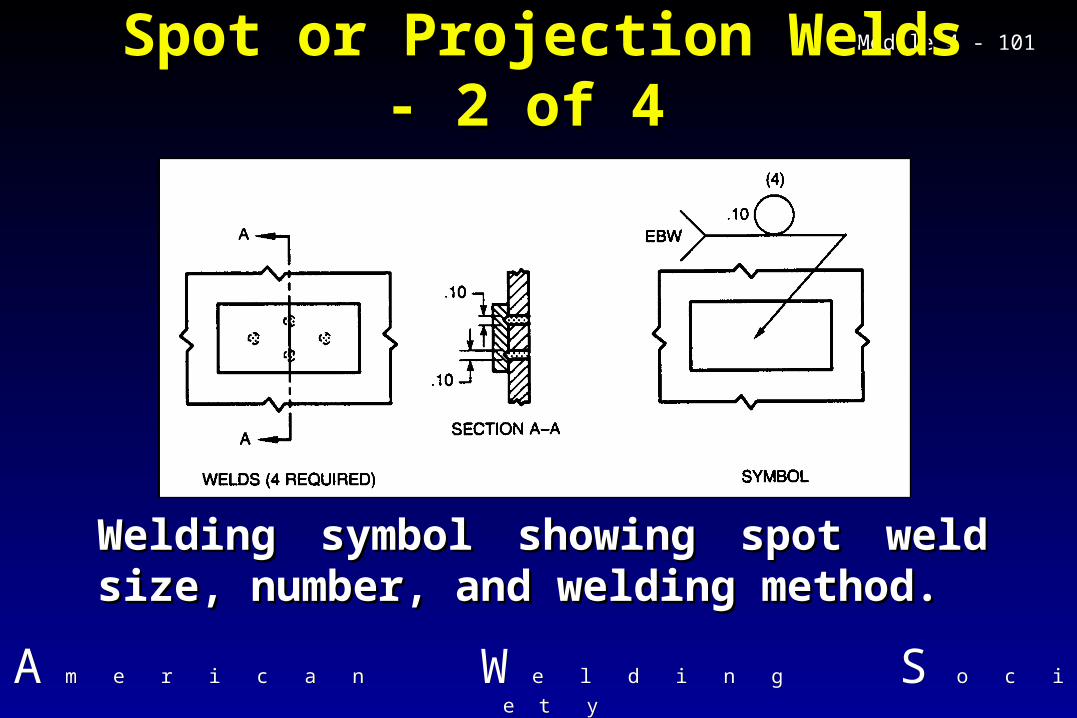
Module 4 - Module 4 - 101101Spot or Projection Welds - Spot or Projection Welds - 2 of 4 2 of 4
Welding symbol showing spot weld Welding symbol showing spot weld size, number, and welding method.size, number, and welding method.

AA m e r i c a nm e r i c a n WW e l d i n ge l d i n g S S o c i e t yo c i e t y
Module 4 - Module 4 - 102102Spot or Projection Welds - Spot or Projection Welds - 3 of 4 3 of 4
Spacing is shown to the right of the Spacing is shown to the right of the symbolsymbol
Number required is shown just Number required is shown just outside the symbol, in parenthesesoutside the symbol, in parentheses

AA m e r i c a nm e r i c a n WW e l d i n ge l d i n g S S o c i e t yo c i e t y
Module 4 - Module 4 - 103103Spot or Projection Welds - Spot or Projection Welds - 4 of 4 4 of 4
Projection weld symbolProjection weld symbol

AA m e r i c a nm e r i c a n WW e l d i n ge l d i n g S S o c i e t yo c i e t y
Module 4 - Module 4 - 104104
Seam Welds - 1 of 2Seam Welds - 1 of 2 Symbol may be on either side, or Symbol may be on either side, or
straddling reference linestraddling reference line Dimensioning as before; size to left Dimensioning as before; size to left
of symbol, length and pitch to rightof symbol, length and pitch to right May be specified by size or strengthMay be specified by size or strength May be continuous or intermittentMay be continuous or intermittent Number shown in parentheses Number shown in parentheses
above or below weld symbolabove or below weld symbol

AA m e r i c a nm e r i c a n WW e l d i n ge l d i n g S S o c i e t yo c i e t y
Module 4 - Module 4 - 105105
Seam Welds - 2 of 2Seam Welds - 2 of 2
Seam weld welding symbol. Note info in Seam weld welding symbol. Note info in tailtail

AA m e r i c a nm e r i c a n WW e l d i n ge l d i n g S S o c i e t yo c i e t y
Module 4 - Module 4 - 106106
Edge Welds - 1 of 3Edge Welds - 1 of 3 Used to specify edge welds on edge Used to specify edge welds on edge
joints and flanged butt or flanged joints and flanged butt or flanged corner jointscorner joints
Full thickness of joint members must Full thickness of joint members must be fusedbe fused
Size to left of symbol, length and pitch Size to left of symbol, length and pitch to rightto right
May be continuous or intermittentMay be continuous or intermittent

AA m e r i c a nm e r i c a n WW e l d i n ge l d i n g S S o c i e t yo c i e t y
Module 4 - Module 4 - 107107
Edge Welds - 2 of 3Edge Welds - 2 of 3
Edge weld symbol applicationEdge weld symbol application

AA m e r i c a nm e r i c a n WW e l d i n ge l d i n g S S o c i e t yo c i e t y
Module 4 - Module 4 - 108108
Edge Welds - 3 of 3Edge Welds - 3 of 3
Edge weld symbol application with 3 Edge weld symbol application with 3 membersmembers

AA m e r i c a nm e r i c a n WW e l d i n ge l d i n g S S o c i e t yo c i e t y
Module 4 - Module 4 - 109109
Stud Welds - 1 of 3Stud Welds - 1 of 3
Stud weld symbol always on arrow Stud weld symbol always on arrow sideside
Size (diameter of stud) to left of Size (diameter of stud) to left of symbol, pitch to rightsymbol, pitch to right
Number in parentheses just outside Number in parentheses just outside symbolsymbol

AA m e r i c a nm e r i c a n WW e l d i n ge l d i n g S S o c i e t yo c i e t y
Module 4 - Module 4 - 110110
Stud Welds - 2 of 3Stud Welds - 2 of 3
Stud weld symbol applicationStud weld symbol application

AA m e r i c a nm e r i c a n WW e l d i n ge l d i n g S S o c i e t yo c i e t y
Module 4 - Module 4 - 111111
Stud Welds - 3 of 3Stud Welds - 3 of 3
Stud weld symbol application, multiple arrowsStud weld symbol application, multiple arrows

AA m e r i c a nm e r i c a n WW e l d i n ge l d i n g S S o c i e t yo c i e t y
Module 4 - Module 4 - 112112
Surfacing Welds - 1 of 3Surfacing Welds - 1 of 3
Surfacing weld symbol always on Surfacing weld symbol always on arrow sidearrow side
Applies to single or multiple layersApplies to single or multiple layers Size (thickness) to left of symbolSize (thickness) to left of symbol Location, direction of welding in tail Location, direction of welding in tail
or a drawing reference or a drawing reference

AA m e r i c a nm e r i c a n WW e l d i n ge l d i n g S S o c i e t yo c i e t y
Module 4 - Module 4 - 113113
Surfacing Welds - 2 of 3Surfacing Welds - 2 of 3
Surfacing weld symbol applicationSurfacing weld symbol application

AA m e r i c a nm e r i c a n WW e l d i n ge l d i n g S S o c i e t yo c i e t y
Module 4 - Module 4 - 114114
Two Weld Layers
Surfacing Welds - 3 of 3Surfacing Welds - 3 of 3
Surfacing weld symbol application, Surfacing weld symbol application, multiple layersmultiple layers

AA m e r i c a nm e r i c a n WW e l d i n ge l d i n g S S o c i e t yo c i e t y
Module 4 - Module 4 - 115115
Brazing Symbols - 1 of 3Brazing Symbols - 1 of 3
Brazing symbol shows joint Brazing symbol shows joint geometry, clearance, type of geometry, clearance, type of braze process, size of braze, braze process, size of braze, pitchpitch
Special cleaning requirements, Special cleaning requirements, before or after brazing, can be before or after brazing, can be noted in tail or on drawingnoted in tail or on drawing

AA m e r i c a nm e r i c a n WW e l d i n ge l d i n g S S o c i e t yo c i e t y
Module 4 - Module 4 - 116116
Brazing Symbols - 2 of 3Brazing Symbols - 2 of 3
Brazing symbol application in scarf jointBrazing symbol application in scarf joint

AA m e r i c a nm e r i c a n WW e l d i n ge l d i n g S S o c i e t yo c i e t y
Module 4 - Module 4 - 117117
Brazing Symbols - 3 of 3Brazing Symbols - 3 of 3
Brazing symbol with dimensions and braze Brazing symbol with dimensions and braze typetype

AA m e r i c a nm e r i c a n WW e l d i n ge l d i n g S S o c i e t yo c i e t y
Module 4 - Module 4 - 118118
NDE Symbols - 1 of 2NDE Symbols - 1 of 2 All conventions used are similar, if All conventions used are similar, if
not identical to Welding Symbolsnot identical to Welding Symbols Must be familiar with NDE Must be familiar with NDE
abbreviations for test methodsabbreviations for test methods Supplementary symbols have Supplementary symbols have
slightly different meaningslightly different meaning Number of tests, extent of testing Number of tests, extent of testing
must be specifiedmust be specified

AA m e r i c a nm e r i c a n WW e l d i n ge l d i n g S S o c i e t yo c i e t y
Module 4 - Module 4 - 119119
NDE Symbols - 2 of 2NDE Symbols - 2 of 2
Note items and position of placementNote items and position of placement

AA m e r i c a nm e r i c a n WW e l d i n ge l d i n g S S o c i e t yo c i e t y
Module 4 - Module 4 - 120120
NDE AbbreviationsNDE Abbreviations
AETAET ETET LTLT MTMT NRTNRT
PTPT PRTPRT RTRT UTUT VTVT

AA m e r i c a nm e r i c a n WW e l d i n ge l d i n g S S o c i e t yo c i e t y
Module 4 - Module 4 - 121121NDE Supplementary NDE Supplementary SymbolsSymbols

AA m e r i c a nm e r i c a n WW e l d i n ge l d i n g S S o c i e t yo c i e t y
Module 4 - Module 4 - 122122NDE Symbol Application - NDE Symbol Application - 1 of 21 of 2
RT symbol, with angle of radiation incidenceRT symbol, with angle of radiation incidence

AA m e r i c a nm e r i c a n WW e l d i n ge l d i n g S S o c i e t yo c i e t y
Module 4 - Module 4 - 123123NDE Symbol Application - NDE Symbol Application - 2 of 22 of 2
MT symbol, both sides for 6 inch lengthMT symbol, both sides for 6 inch length

AA m e r i c a nm e r i c a n WW e l d i n ge l d i n g S S o c i e t yo c i e t y
Module 4 - Module 4 - 124124
A2.4-98 - Back of BookA2.4-98 - Back of Book Table 1 - letter designations of processesTable 1 - letter designations of processes Table 2 - alphabetical cross reference to Table 2 - alphabetical cross reference to
Table 1 by processTable 1 by process Table 3 - alphabetical cross reference to Table 3 - alphabetical cross reference to
Table 1 by letter designationTable 1 by letter designation Annex A & AM - Design of Standard SymbolsAnnex A & AM - Design of Standard Symbols Annex B - Commentary on A2.4-98Annex B - Commentary on A2.4-98 Welding Symbol ChartWelding Symbol Chart