module 3: physical layer - jackson state university
TRANSCRIPT

1
Module 3: Physical Layer
Dr. Natarajan Meghanathan
Associate Professor of Computer Science
Jackson State University
Jackson, MS 39217
Phone: 601-979-3661
E-mail: [email protected]
All Cop
yrigh
ts
Nataraj
an M
egha
natha
n

2
Topics
• 3.1 Signal Levels: Baud rate and Bit rate
• 3.2 Channel Encoding Standards
– RS-232 and Manchester Encoding
– Delay during transmission
• 3.3 Transmission Order of Bits and Bytes
• 3.4 Modulation Techniques
– Amplitude, Frequency and Phase modulation
• 3.5 Multiplexing Techniques
– TDMA, FDMA, Statistical Multiplexing and CDMA
All Cop
yrigh
ts
Nataraj
an M
egha
natha
n

3.1 Signal Levels: Baud Rate and Bit Rate
All Cop
yrigh
ts
Nataraj
an M
egha
natha
n

4
Analog and Digital Signals
• Data communications deals with two
types of information:
– analog
– digital
• An analog signal is characterized by a continuous mathematical function
– when the input changes from one value
to the next, it does so by moving through
all possible intermediate values
• A digital signal has a fixed set of valid levels
– each change consists of an
instantaneous move from one valid level
to anotherAll C
opyri
ghts
Nataraj
an M
egha
natha
n

5
Digital Signals and Signal Levels
• Some systems use voltage to represent digital values
– by making a positive voltage correspond to a logical one
– and zero voltage correspond to a logical zero
• For example, +5 volts can be used for a logical one and 0 volts for a
logical zero
• If only two levels of voltage are used
– each level corresponds to one data bit (0 or 1).
• Some physical transmission mechanisms can support more than two
signal levels
• When multiple digital levels are available
– each level can represent multiple bits
• For example, consider a system that uses four levels of voltage:
-5 volts, -2 volts, +2 volts, and +5 volts
– Each level can correspond to two bits of data as Figure 6.8 illustrates
All Cop
yrigh
ts
Nataraj
an M
egha
natha
n

6
Digital Signals and Signal Levels
Digital signal using 2-voltage levels
Digital signal using 4-voltage levels
All Cop
yrigh
ts
Nataraj
an M
egha
natha
n

© 2009 Pearson Education Inc., Upper Saddle River, NJ. All rights reserved. 7
Digital Signals and Signal Levels
• The relationship between the number of levels required and the number of bits to be sent is straightforward
• There must be a signal level for each possible combination of bits
• There are 2n combinations possible with n bits– a communication system must use 2n levels to represent n bits
• One could achieve arbitrary numbers of levels by dividing voltage into arbitrarily small increments– Mathematically, one could create a million levels between 0 and 1
volts merely by using 0.0000001 volts for one level, 0.0000002 for the next level, and so on
• Practical electronic systems cannot distinguish between signals that differ by arbitrarily small amounts– Thus, practical systems are restricted to a few signal levels
7
All Cop
yrigh
ts
Nataraj
an M
egha
natha
n

8
Baud and Bits Per Second • How much data can be sent in a given time?
– The answer depends on two aspects of the communication system.
• The rate at which data can be sent depends on
– the number of signal levels
– the amount of time the system remains at a given level before moving to the
next
• As with signal levels, the hardware in a practical system places limits on
how short the time can be
– if the signal does not remain at a given level long enough, the receiving
hardware will fail to detect it
• The accepted measure of a communication system does not specify a
length of time
– how many times the signal can change per second, which is defined as the
baud
– for example, if a system requires the signal to remain at a given level for
.001 seconds, we say that the system operates at 1000 baud
• Both baud and number of signal levels control bit rateAll C
opyri
ghts
Nataraj
an M
egha
natha
n

© 2009 Pearson Education Inc., Upper Saddle River, NJ. All rights reserved. 9
Baud and Bits Per Second
• If a system with two signal levels operates at 1000 baud
– the system can transfer exactly 1000 bits per second
• If a system that operates at 1000 baud has four signal levels
– the system can transfer 2000 bits per second (because four signal
levels can represent two bits)
• Equation below expresses the relationship between baud, signal levels, and bit rate
9
All Cop
yrigh
ts
Nataraj
an M
egha
natha
n

3.2 Channel Encoding Standards
All Cop
yrigh
ts
Nataraj
an M
egha
natha
n

© 2009 Pearson Education Inc., Upper Saddle River, NJ. All rights reserved. 11
Asynchronous Transmission
• It is asynchronous if the system allows the physical medium
to be idle for an arbitrary time between two transmissions
• The asynchronous style of communication is well-suited to
applications that generate data at random
– (e.g., a user typing on a keyboard or a user that clicks on a link)
• The disadvantage of asynchrony arises from the lack of coordination between sender and receiver
– While the medium is idle, a receiver cannot know how long the
medium will remain idle before more data arrives
• Asynchronous technologies usually arrange for a sender to transmit a few extra bits before each data item
– to inform the receiver that a data transfer is starting
– extra bits allow the receiver to synchronize with the incoming signal
– the extra bits are known as a preamble or start bits
11
All Cop
yrigh
ts
Nataraj
an M
egha
natha
n
© 2009 Pearson Education Inc., Upper Saddle River, NJ. All rights reserved. 12
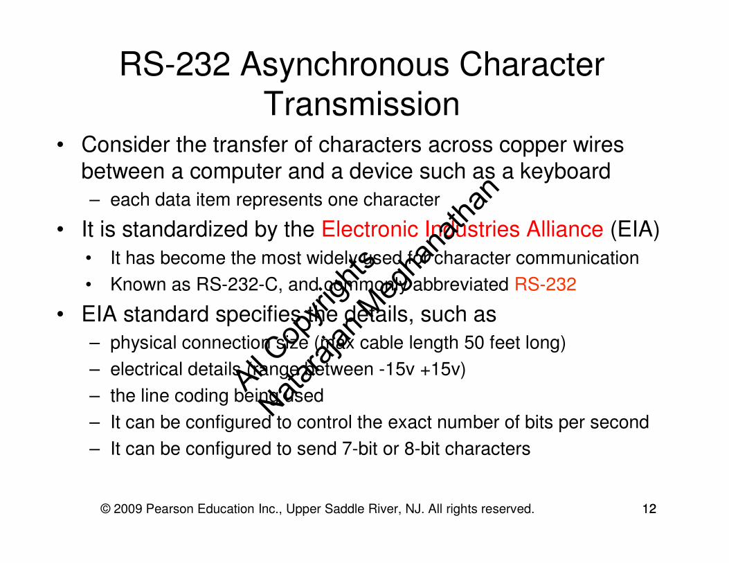
RS-232 Asynchronous Character
Transmission • Consider the transfer of characters across copper wires
between a computer and a device such as a keyboard
– each data item represents one character
• It is standardized by the Electronic Industries Alliance (EIA)
• It has become the most widely used for character communication
• Known as RS-232-C, and commonly abbreviated RS-232
• EIA standard specifies the details, such as
– physical connection size (max cable length 50 feet long)
– electrical details (range between -15v +15v)
– the line coding being used
– It can be configured to control the exact number of bits per second
– It can be configured to send 7-bit or 8-bit characters
12
All Cop
yrigh
ts
Nataraj
an M
egha
natha
n

RS-232 Asynchronous Character
Transmission
© 2009 Pearson Education Inc., Upper Saddle River, NJ. All rights reserved. 13
Figure above illustrates how voltage varies at different stages when a
start bit, eight bits of a character, and a stop bit are sent
13
All Cop
yrigh
ts
Nataraj
an M
egha
natha
n

© 2009 Pearson Education Inc., Upper Saddle River, NJ. All rights reserved. 14
Manchester Encoding
• In addition to the RS-232 standard, one particular standard
for line coding is especially important for networks:
– Manchester Encoding used with Ethernet
• Detecting a transition in signal level is easier than measuring the signal level
• This fact explains why Manchester Encoding uses transitions rather than levels to define bits
• In Manchester Encoding, a 1 corresponds to a transition from negative voltage level to a positive voltage level
– Correspondingly, a 0 corresponds to a transition from a positive
voltage level to a negative level
– The transitions occur in the “middle” of the time slot of a bit
• Figure 6.13a illustrates the concept
14
All Cop
yrigh
ts
Nataraj
an M
egha
natha
n

© 2009 Pearson Education Inc., Upper Saddle River, NJ. All rights reserved. 15
Manchester Encoding
Manchester Encoding uses a 64-bit preamble(alternating 0s and 1s)
15
All Cop
yrigh
ts
Nataraj
an M
egha
natha
n

Delays• In network communication, the delay incurred to send data
from a source to destination is a combination of the following components: – Transmission Delay
– Propagation Delay
– Queuing Delay (including the Switching Delay)
• Transmission Delay – the delay incurred to insert the bits of a packet onto a channel of a given bandwidth
• Propagation Delay – the delay incurred for a packet to propagate (for the signal to move) on a channel of a particular length
Packet Size (bits)
Transmission Delay = -----------------------------------------
Channel Bandwidth (bits/sec)
Channel Length (m)Propagation Delay = -----------------------------------------
Speed of the Signal (m/s)16
All Cop
yrigh
ts
Nataraj
an M
egha
natha
n

Sample Question: RS-232 Std. & Delay
• Determine the transmission delay, propagation delay and the total delay
incurred to transmit data of size 2000 characters using the RS-232
standard. Assume the channel bandwidth is 40000 bits/sec and length is
2*106m. Assume the speed of the signal on the channel is 60% of the
speed of light.
• Solution:
– To transmit a character according to the RS-232 standard, 10 bits (8 data
bits plus 1 start and 1 stop bits) are needed. Hence, to transmit 2000
characters, we need 2000 * 10 = 20,000 bits
– Transmission Delay = Data Size/ Channel Bandwidth
= (20,000 bits)/ (40,000 bits/sec) = 0.50 sec
– Propagation Delay = Channel length/ speed of the signal on the channel
= (2 * 106 m)/ (0.6 * 3 * 108 m/s) = 0.011 sec
– Total Delay = Transmission Delay + Propagation Delay = 0.511 sec
17
All Cop
yrigh
ts
Nataraj
an M
egha
natha
n

3.3 Transmission Order
All Cop
yrigh
ts
Nataraj
an M
egha
natha
n

© 2009 Pearson Education Inc., Upper Saddle River, NJ. All rights reserved. 19
Transmission Order: Bits and Bytes
• In serial mode, when sending bits, which bit should be sent
across the medium first?
• Consider an integer: Should a sender transmit
– the Most Significant Bit (MSB)
– or the Least Significant Bit (LSB) first?
• We use the term little-endian to describe a system that sends the LSB first
• We use the term big-endian to describe a system that sends the MSB first
• Either form can be used, but the sender and receiver must agree
19
All Cop
yrigh
ts
Nataraj
an M
egha
natha
n

© 2009 Pearson Education Inc., Upper Saddle River, NJ. All rights reserved. 20
Transmission Order: Bits and Bytes
• The order in which bits are transmitted does not settle the
entire question of transmission order
– Data in a computer is divided into bytes, and each byte is further
divided into bits (typically 8 bits per byte)
– Thus, it is possible to choose a byte order and a bit order
independently
– For example, Ethernet technology specifies that data is sent byte
big-endian and bit little-endian, as shown below for a 32-bit data
20
All Cop
yrigh
ts
Nataraj
an M
egha
natha
n

Sample Question: Transmission Order of Bits
and Bytes• Consider the word ‘ANT’ with the ASCII values of ‘A’, ‘N’ and ‘T’ being
65, 78 and 84 respectively. How would this word be transmitted if the
transmission order is:
– Byte little-endian and bit big-endian?
– Byte big-endian and bit little-endian?
0 1 0 0 0 0 0 1 0 1 0 0 1 1 1 0 0 1 0 1 0 1 0 0
65 (A)
Byte 3
78 (N)
Byte 2
84 (T)
Byte 1
1 2 3 89 10 1617 18 24
0 1 0 0 0 0 0 1 0 1 0 0 1 1 1 0 0 1 0 1 0 1 0 0
65 (A)
Byte 1
78 (N)
Byte 2
84 (T)
Byte 3
24 23 1716 15 98 7 121
All Cop
yrigh
ts
Nataraj
an M
egha
natha
n

3.4 Modulation Techniques
All Cop
yrigh
ts
Nataraj
an M
egha
natha
n

Amplitude Modulation• The amplitude of the carrier is modulated to encode data
• The strength of the carrier signal in (b) is reduced to 2/3rd of its
Amplitude to encode a 1 bit and to 1/3rd of the Amplitude to encode
0 bit
23
All Cop
yrigh
ts
Nataraj
an M
egha
natha
n

Frequency Modulation
• The frequency of the carrier wave is changed to encode the transmission of the bits.
• The two binary digits are represented by two different frequencies that are offset from the carrier frequency by equal but opposite amount.
• Frequency of the carrier wave = fc,
• Frequency of binary digit 0 = f0,
• Frequency of binary digit 1 = f1.
• f0 < fc < f1 ; fc – f1 = fc – f024
All Cop
yrigh
ts
Nataraj
an M
egha
natha
n

Frequency Modulation - Example• Assume the bits are encoded for every two cycles (i.e., two cycles
per unit time). Then, to encode data, we could change the frequency
to one cycle (for bit 0) and three cycles (for bit 1)per unit time
respectively.
• Assume the sequence of bits to be transmitted is: 0 1 _ 0, where _
indicates the channel is idle.
25
0 1 _ 0All C
opyri
ghts
Nataraj
an M
egha
natha
n

Phase Modulation
• The timing of the carrier wave is abruptly changed with a phase shift.
• Section of the wave is omitted at phase shift.
• The number of possible shifts that can be detected by the hardware within a cycle of the carrier wave determines the number of bits encoded per phase shift.
26
All Cop
yrigh
ts
Nataraj
an M
egha
natha
n

Phase Modulation• The timing of the carrier wave is abruptly changed with a phase shift.
Two-level Phase Shift Keying (BPSK)
Use two phases to represent binary digits
A sin (2 π f t) Carrier
• Signal strength s(t) = A sin (2 π f t + π/2) Bit 0
A sin (2 π f t + 3π/2) Bit 1
• Can we do better? (i.e., can we encode multiple bits in a single cycle of the carrier?)
• Answer: Yes, using Multiple Phase Shift Keying and Multiple Frequency Shift Keying.
Not possible using amplitude modulation. Why?
27
All Cop
yrigh
ts
Nataraj
an M
egha
natha
n

Phase Modulation: Example
0 1 1 _ 0 1 0
Strength: Less bandwidth
Weakness: The sender and
receiver need to be frequently
resynchronized to correctly
detect the phase shifts
Phase Shifts
0 – π/2
1 - 3π/2
All Cop
yrigh
ts
Nataraj
an M
egha
natha
n

Phase Modulation
Example
Each signal element represents two bits
A sin (2 π f t) Carrier
A sin ( 2 π f t + π/4) bits 00
Signal strength S(t) = A sin (2 π f t + 3π/4) bits 01
A sin (2 π f t + 5π/4) bits 10
A sin (2 π f t + 7π/4) bits 11
29
All Cop
yrigh
ts
Nataraj
an M
egha
natha
n

3.5 Multiplexing Techniques
All Cop
yrigh
ts
Nataraj
an M
egha
natha
n

Multiplexing
• Broadband Technology - Technology that uses a large bandwidth
of the electromagnetic spectrum to achieve higher throughput (data
transmitted per second). E.g., FDM, WDM (Wavelength Division
Multiplexing – FDM when applied optical transmission systems and
systems that use radio frequencies)
• Baseband Technology - Technology that uses a smaller bandwidth
of the electromagnetic spectrum and sends only one signal at a time
are called baseband technologies. E.g., TDM, Statistical
multiplexing
• Spread spectrum multiplexing
Transfer the same data using multiple signals at the same frequency
or different frequency.
Goal: To provide reliability if certain carriers encounter interference.31
All Cop
yrigh
ts
Nataraj
an M
egha
natha
n

Time Division Multiplexing (TDM)
• Use a single carrier to carry the data of multiple transmitter/receiver pairs in a round-robin fashion.
S
t
r
e
a
m
1
S
t
r
e
a
m
2
S
t
r
e
a
m
3
S
t
r
e
a
m
4
S
t
r
e
a
m
5
S
t
r
e
a
m
1
S
t
r
e
a
m
2
S
t
r
e
a
m
3
S
t
r
e
a
m
4
S
t
r
e
a
m
5
time
32
All Cop
yrigh
ts
Nataraj
an M
egha
natha
n
Sample Question: TDM
• Assume two computers using time division multiplexing to
take turns in sending 512 byte packets over a shared channel that operates at 40000 bits/second. If the hardware takes 10 msec after one computer stops sending before the other can begin, how long it will take for each of the two computers to send 1 MB of a file?
33
All Cop
yrigh
ts
Nataraj
an M
egha
natha
n
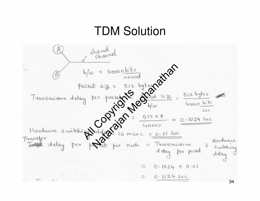
TDM Solution
34
All Cop
yrigh
ts
Nataraj
an M
egha
natha
n

TDM Solution (continued…)Timeline
35
All Cop
yrigh
ts
Nataraj
an M
egha
natha
n

Frequency Division Multiplexing (FDM)
• FDM – technique of using multiple carrier frequencies to allow independent signals to travel through a
medium.
• To avoid interference,
– A minimum separation between the frequencies of the carriers
is needed.
– The carrier frequencies should not be multiples of each other.
Hence, FDM is used only on high-bandwidth transmission
systems.
36
All Cop
yrigh
ts
Nataraj
an M
egha
natha
n
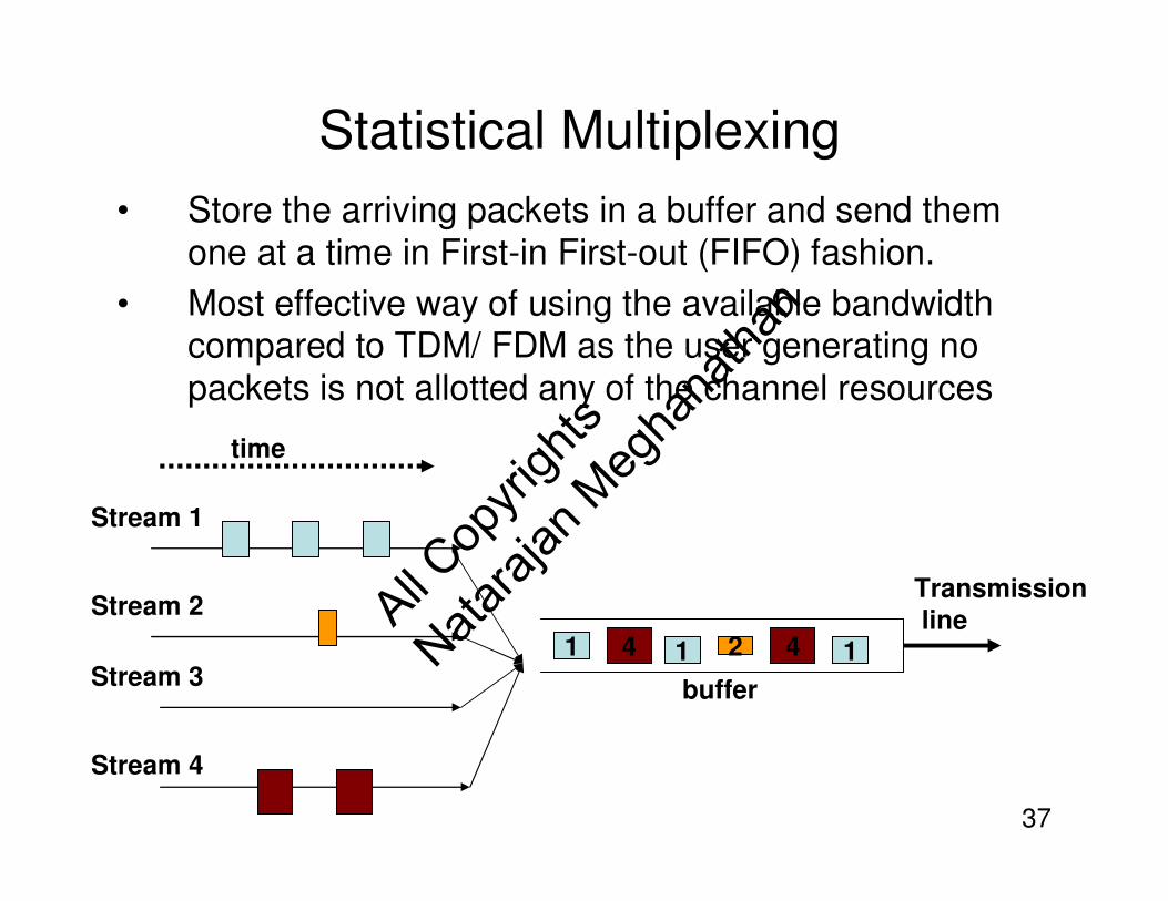
Statistical Multiplexing
• Store the arriving packets in a buffer and send them one at a time in First-in First-out (FIFO) fashion.
• Most effective way of using the available bandwidth compared to TDM/ FDM as the user generating no
packets is not allotted any of the channel resources
Stream 1
Stream 2
Stream 3
Stream 4
1 4 21 4 1
time
Transmission
line
buffer
37
All Cop
yrigh
ts
Nataraj
an M
egha
natha
n

Code Division Multiplexing (CDM)• CDM used in parts of the cellular telephone system and for some
satellite communication– The specific version of CDM used in cell phones is known as Code
Division Multi-Access (CDMA)
• CDM does not rely on physical properties– such as frequency or time
• CDM relies on an interesting mathematical idea– values from orthogonal vector spaces can be combined and separated
without interference
• Each sender is assigned a unique binary code Ci
– that is known as a chip sequence
– chip sequences are selected to be orthogonal vectors
– (i.e., the dot product of any two chip sequences is zero)
• At any point in time, each sender has a value to transmit, Vi
– The senders each multiply Ci x Vi and transmit the results
• The senders transmit at the same time– and the values are added together
• To extract value Vi, a receiver multiplies the sum by Ci
38
All Cop
yrigh
ts
Nataraj
an M
egha
natha
n

CDM Example - Question
• Sample Question: Use Code Division Multiplexing to transmit the data values 0 1 1 0 and 1 0 1 0 from two
senders S1 and S2 respectively. The 2-bit Chip Sequence of S1 and S2 are 0 1 and 1 1 respectively.
– Show the resulting signal values when the two above two data
signals are transmitted simultaneously
– Show how the receiver for the data signals sent by S1 and S2 are
able to decode the data?
39
All Cop
yrigh
ts
Nataraj
an M
egha
natha
n

CDM Example - Solution
• Let the Senders be represented as S1 and S2.
• Data D1 = [0 1 1 0] and D2 = [1 0 1 0]
• Chip Sequence C1 = [0 1] and C2 = [1 1]
• In all our computations, we will replace ‘0’ with ‘-1’ and then revert
back to 0 at the end of the computation.
• Accordingly, D1 = [-1 1 1 -1]; D2 = [1 -1 1 -1]; C1 = [-1 1]; C2 = [1 1]
• Initial Step: To check if the chip sequences are orthogonal
• C1*C2 = [-1 1] * [1 1] = (-1)(1) + (1)(1) = -1 + 1 = 0
• Since the product is 0, we say C1 and C2 are orthogonal.
• Encoding at S1: The signal transmitted by the sender S1 is
• S1 = C1T * D1
-1
12x1
* [-1 1 1 -1]1x4
=1 -1 -1 1
-1 1 1 -1
2x4
40
All Cop
yrigh
ts
Nataraj
an M
egha
natha
n

CDM Example – Solution (contd..)• Encoding at S2: The signal transmitted by the sender S2 is
• S2 = C2T * D2
• Composite Signal Received at each Destination, S = S1 + S2
• Retrieving the Data at the Receiver for S1: = C1 * S
1
12x1
* [1 -1 1 -1]1x4
=1 -1 1 -1
1 -1 1 -1
2x4
1 -1 -1 1
-1 1 1 -1
2x4
S = + 1 -1 1 -1
1 -1 1 -1=
2 -2 0 0
0 0 2 -2
2x4
= [-1 1] * 2 -2 0 0
0 0 2 -2
2x4
1x2=
1x4[-2 2 2 -2]
Dividing by 2, the data received from S1 = [-1 1 1 -1] � [0 1 1 0] 41
All Cop
yrigh
ts
Nataraj
an M
egha
natha
n

CDM Example – Solution (contd..)• Retrieving the Data at the Receiver for S2: = C2 * S
= [1 1] * 2 -2 0 0
0 0 2 -2
2x4
1x2=
1x4[2 -2 2 -2]
Dividing by 2, the data received from S1 = [1 -1 1 -1] � [1 0 1 0]
42
All Cop
yrigh
ts
Nataraj
an M
egha
natha
n