module 3
DESCRIPTION
virtual environemntsTRANSCRIPT

Jessie (Jie Wen) Wen
Student No: 586655 Semester 1/2011 Group 8

With the model I made in Module II, what I was most worried about was the rigidity and structure, as the offset borders were quite large because of the offset points which were set at 4cm.
I made a A4 sized paper model of a few strips of the panels of my model using printing paper to see how they would turn out. What I found was that they were very fragile. Even though I know the material plays a big role, the 4cm offset was a big problem I knew needed to be changed.
Remodelling

From my original model, the first thing I needed to change was the offset points because through the testing of making the panels, I knew it would be very difficult, and also frail. Therefore, I decided to change the offset bor-ders to 1cm instead. Whilst reviewing my model, I also realized that the spikes at the end weren’t part of my initial concept of a flowing form. Instead, it was a very dynamic change from smaller pyramids to giant spikes. Thus, I decided to get rid of these spikes.

I ended up deciding to choose offset points 2cm as I experi-mented whith different lengths because 1cm appeared too low for the scale of my model and would make it seem unbal-ance. and to keep offset bor-ders because the holes would be decreased, making the structure easier to build, and less frail than compared to off-set points of 4cm.
Also, as the offset borders are lower, it would increase the wave-like motion, a gentler flow on the surface, which coincid-ed with my initial concept of a wavelike structure representing the dispersing of spores through wind.

Initially, I planned to make a backbone ridge and then unroll panels along the u lines making it easy to remember the order of the pane.s However, I soon come to a hurdle as I realized the un-rolled faces strip had many spikes, cre-ating a difficulty when I came to mak-ing tabs.
So I devised another way, the ‘moun-tain and valley’ method, crossing di-agnolly along my model. This creat-ed much more suitable strips, as they didn’t have sharp edges.

Labelling Process
I decided to use different colours for each strip to make it quicker to identify each strip. Also used Dot to label strips.To make constructing the model more easily, I decided to section my model into three parts.

Unrolling Process

I then used DupEdge to replicate edges of my panels. Then the command SelDup to make sure there wasn’t two edges or this mistake would affect the Fablab process. Now it was ready to be prepared for fablab preparations.

Nesting
Initially, I had set them all out in order of number to not get confused when I went to cut them out, however following that method produced six pages. So, I went on to keep as many in order as possible but to try and move a few panels around to try and save pages and space, thus, being able to cut down to evenly spaced five pages to save material.
Page 1 Page 2 Page 3
Page 4 Page 5
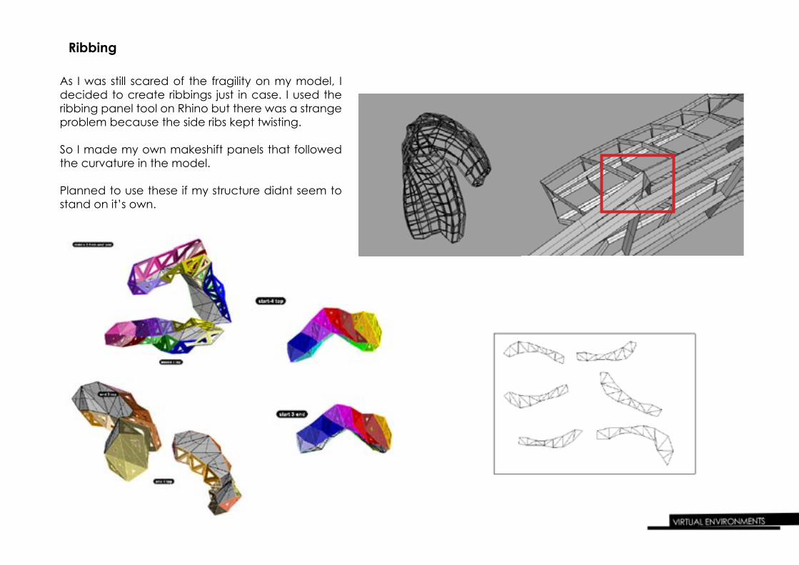
As I was still scared of the fragility on my model, I decided to create ribbings just in case. I used the ribbing panel tool on Rhino but there was a strange problem because the side ribs kept twisting.
So I made my own makeshift panels that followed the curvature in the model.
Planned to use these if my structure didnt seem to stand on it’s own.
Ribbing

I thought the decision on tabs would be important. I chose out of the two simplest tabbing, either joining the tabs on both panels together or pasting one tab onto the next panel.
I decided to go with the first trial which was joining the tabs on both panels together. I think it doesn’t create the darker shaded area on the panels and would also be easier to join.
The only thing I don’t like too much on this choice is that there are light seams shining through, but then I also thought that thsi enhaned the idea of spores being released and blown around
Tabs

Prototype- 1:1 Scale Ivory Card
I had tested out panels using printed paper but I decided to make a prototype out of the front part of my model because it was the easi-est to test out how to put it together and the ivory card I planned to use. With the time consraint, I knew I wouldn’t have time to finish a whole prototype.
The main thing I wanted to test out was whether I liked this material and it I believed the model would work. I discovered I liked this mate-rial, it was thicker than average paper giving the structure more rigid-ity but also not too rigid like mountboard so it would still have some fluidity as my model is a wavelike motion.
I relized it was a very smart decision to have done the changes to my design earlier on in Module III to amke this process easier. Also expected, using ivory card is much more rigid and stable compared to printing paper.
Prototype
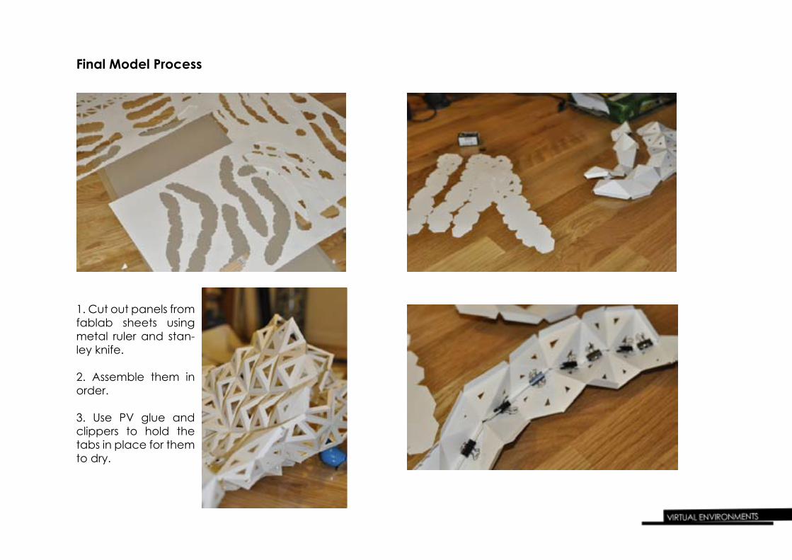
Final Model Process
1. Cut out panels from fablab sheets using metal ruler and stan-ley knife.
2. Assemble them in order.
3. Use PV glue and clippers to hold the tabs in place for them to dry.
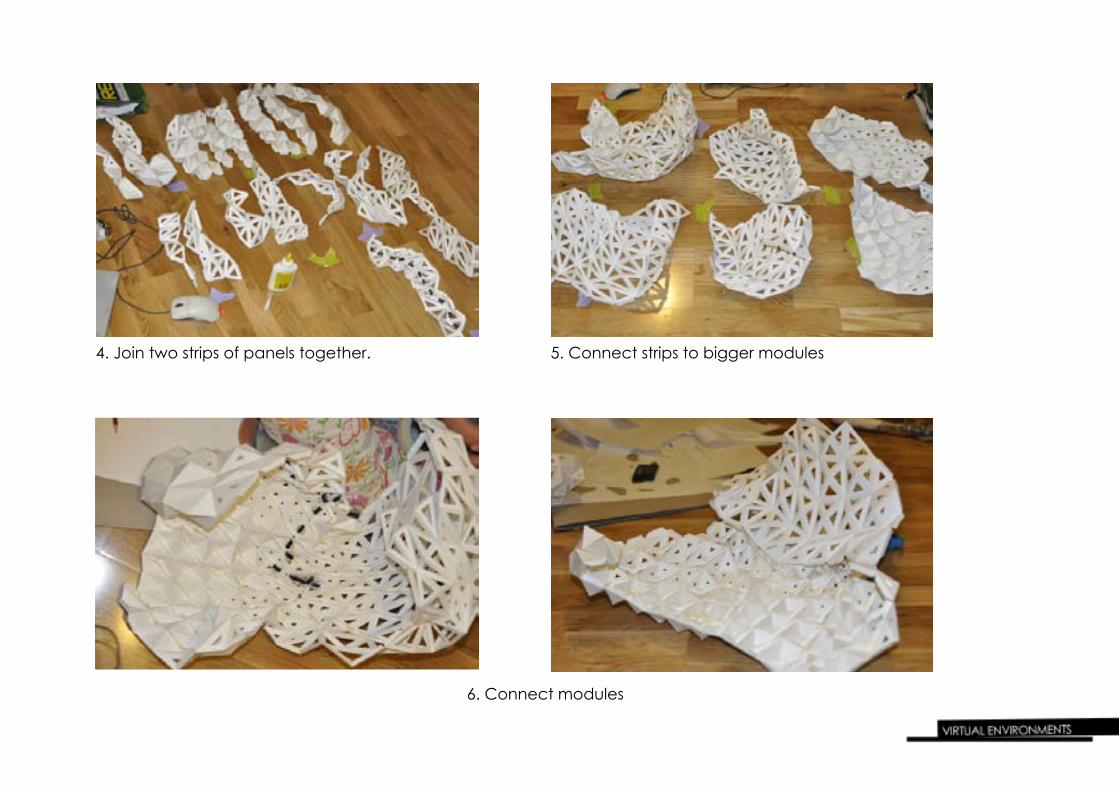
4. Join two strips of panels together. 5. Connect strips to bigger modules
6. Connect modules

- 6 white LED lights- one switch- electric tape- wires
I decided to use 6 LED lights so as to get a brighter lighting than just the 3 provided, Also, it would give a more evenly dispersal of light and allow me to experiment more to cre-ate affects that coincided with my concept of spore dis-persal, already shown through the offset borders.
Assembling lighting

Lighting Experimentation
Lights dispersed evenly to create a flowing movement of light density as the offset border faces realizes my inital concept of lighting shin-ing through more brightly and with more inten-sity as the spores flow away.
Lights outside and lights are condensed into one spot. The intensity and concentration in one spot gives the model a lot of dynamic, however I prefer the full lighting compared to this partial lighting as it conveys my concept better.

Playing wtih shadows:
At different angles , the panels created quite interesting shadlows, from smaller to larger triangles, much like dense to sparse spores in the open.
I managed to create a wisp like shadow by facing the front of the model at a angle I was playing with which has made my choice definite that this would be the front

Precedent
Fablab House by IAAC:The Fablab House was created by Institute for Advanced Architecture of Catalonia. Vicente Guallart, Director of the IAAC: “Buildings must be like trees, which are self sufficient, and must follow natural principles. Rather than built, the pro-ject was manufactured, as digital manufacturing machine tools (known as 3D printers) were used in the construction pro-cess. This process partakes on the humanistic idea, advocat-ed by Guallart, that things must be again produced in cities. Says Guallart “We produced our solar house with researchers, in accordance with medieval principles: the designer and the builder are the same person.”
It links closely to the project of what we’re doing, using com-puterized software to create a 3D structure that can be used by people. Like our process, it has needed to underwent strenuous modification to achieve it’s goal, in their case, to be environmentally friendly. Also like our project, the project has relied on our imagination and ideas of the natural process we have chosen. We have decided on different modifications to produce the best results for us, the designers to build.

Precedent The Angelin Lamp:Contemporary light by talented Paris designer, Constance Guisset. It is made of a metallic structure containing a neon and also a few rolls of paper. It allows for the user to creates his own luminous atmosphere as desired. By changing the density of paper in one spot or the length, it allows for the light to change in warmth and transparency. I find it relates to our project very closely because whilst the computer component has been a main focus, I think the lighting is also an impor-tant aspect which is why experimenting with lights is essential. From The Angelin Lamp, it is able to clearly show why lighting is important, as it can change the dynamic, mood of the audience and user. Also, the material of paper is much like our project and allows for many choices and variations in this one simple piece of material.

Final Product
Reflection
Module III has been the toughest. Not only did it require a lot of time, but also effort and concentration, and this was especially hard as we had to work to a time limit.
Through Module III, it has been a clear process of testing, doing it again, retesting and so on. Whilst this is the best method for achieving the best result, it would have been better with more time given. However, as in the real world, not only do architects and designers have to work to constraining time scedules but also dentists and teachers, so this skill would be required throughout all professions.
Even though the 3D computerized designs on the screen appear to be functioning, I felt that there were many unexpected differences from on screen to real life. The ma-terial, construction process, precision of the machine or whether the construction will actually work in real life. I still find that the designer gets to choose what goes on the model and what gets left out and discarded, however, as said in the Week 10 lecture, sometimes the final product can exceed the design. I would find it true in this case because I had no idea on the choices provided by Rhino and designing is a very new process to me.
Overall, I think that digitization enables architects and designers to have more control over their designs in what they choose to use and change to create the best possible outcome.
Whilst this module has been rewarding and now see the prospects of using computer software for designing, However, I would have liked more time as this module was very critical and time consuming.