modular design of integrated duct fan quadrotor structure
TRANSCRIPT

Faculty of Engineering Science and Technology
Modular Design of Integrated Duct Fan
Quadrotor Structure
—
Sven Ole Hoff and André Rones
Master’s thesis in Engineering Design June 2017

Modular Design of Integrated Duct Fan Quadrotor Structure

Modular Design of Integrated Duct Fan Quadrotor Structure
Master of Science
UiT – The Arctic University of Norway in Narvik Lodve Langes gate 2, 8514 Narvik
Postbox 385
8505 NARVIK
Tlf: 77 64 40 00
Title:
Modular Design of Integrated Duct Fan Quadrotor Structure
Date:
6/6/2017
Authors:
Sven Ole Hoff & André Rones
Classification:
Open
Department:
Department of Computer Science and Computational Engineering
Pages: 41
Attachments: 6
Faculty:
Faculty of Engineering Science and Technology
Study Program:
Engineering Design
Supervisors:
Guy Beeri Mauseth & Per Johann Nicklasson
Keywords:
Ducted fan, modular, lightweight, quadrotor.
Abstract:
This thesis will continue the work done by Sethuram Balakrishnan in his master thesis “Duct fanned
shielding design for quadrotors”. It includes studies of integrating Balakrishnan’s solution to the outer
structure of the DJI Flame Wheel F450 Quadrotor in order to save weight. A report with preliminary
work will cover investigation of existing solutions and technology, setting design requirements and
explore standards given by the government. The goal was to reduce mass from the previous design,
make it modular and retain the mechanical properties of the quadrotor. Concepts were created and
evaluated with the systematic design process explained by Nigel Cross in his book “engineering
design methods”. Materials was selected in CES by maximizing the material index for a low mass/stiff
construction. Numerical analysis in Inventor was done to verify the structural integrity of the model,
and a prototype was constructed to give a real perspective of the model. The process produced a final
design that was 500g lighter than Balakrishnan’s design, modular and cost effective. This means a
43,5% reduction in mass. The results in theory are interesting, and if results from physical testing
corresponds, it will possibly have implications for production of drones with a need for increased
thrust and protected propellers.

Modular Design of Integrated Duct Fan Quadrotor Structure
Acknowledgments This thesis was carried out at the Faculty of Engineering Science and Technology at UiT – The Arctic
University of Norway, campus Narvik under the supervision of Guy Beeri Mauseth and Per Johan
Nicklasson. We want to thank our supervisors for the guidance and encouragements throughout the
project. As relatively new to the quadrotor and drone technology we want to thank Tor-Alexander
Johansen, contact person at the UiT department of electrotechnology, which helped us with problems
and gave us ideas during the project. Erlend Bjørk has helped us with 3D printing and shared his
experience within the 3D printing technology with us, we are grateful for his help. A thank to our
fellow students for discussing the aspects of our project with us and in that way helped and inspired
us. At last we want to thank UiT – The Arctic University of Norway for letting us use the facilities at
the school.

Modular Design of Integrated Duct Fan Quadrotor Structure
Table of Contents Master of Science .................................................................................................................................... 1
UiT – The Arctic University of Norway in Narvik ........................................................................ 1
Acknowledgments ................................................................................................................................... 2
List of tables ............................................................................................................................................ 5
Abbreviations .......................................................................................................................................... 6
1 Introduction .................................................................................................................................... 1
1.1 Background ............................................................................................................................. 1
1.2 Problem description ................................................................................................................. 2
2 Design process ................................................................................................................................ 3
2.1 Customer and design requirements ......................................................................................... 3
2.1.1 Stiffness test .................................................................................................................... 4
2.2 Generating concepts ................................................................................................................ 5
Morphological chart ....................................................................................................................... 7
Evaluation matrix ........................................................................................................................... 7
2.3 Rapid prototyping .................................................................................................................... 8
2.3.1 Specifications .................................................................................................................. 9
2.3.2 Stiffness test of 3D printed solution and original arm ................................................... 10
3 Final design................................................................................................................................... 12
3.1 Early sketches ........................................................................................................................ 13
3.2 Evaluation of different solutions ........................................................................................... 14
3.3 3D model ............................................................................................................................... 15
4 Materials selection ........................................................................................................................ 17
4.1 Duct ....................................................................................................................................... 17
4.2 Support ring ........................................................................................................................... 22
4.3 Top cover ............................................................................................................................... 24
5 Main results from numerical computations .................................................................................. 25
5.1 Analysis of ring ..................................................................................................................... 25
5.1.1 Results from numeric simulations of ring ..................................................................... 27
5.1.2 Analytical calculation of ring ........................................................................................ 28
5.2 Analysis of duct ..................................................................................................................... 30
5.2.1 Results from numerical simulation of duct ................................................................... 31
5.3 Simulation of whole duct structure........................................................................................ 32
6 Results and discussion .................................................................................................................. 34
6.1 Prototype ............................................................................................................................... 37
Modular Design of Integrated Duct Fan Quadrotor Structure
7 Conclusion .................................................................................................................................... 38
7.1 Suggestions for future work .................................................................................................. 39
8 References .................................................................................................................................... 40
Appendix ................................................................................................................................................. 1
A. 3D models from Inventor ................................................................................................................... 1
B. 2D drawings ........................................................................................................................................ 5
C. Thrust values from Balakrishnan’s testing. ...................................................................................... 10
D. Simulations ....................................................................................................................................... 11
Stress analysis ................................................................................................................................... 11
Stress analysis setup ..................................................................................................................... 11
Stress analysis report ring structure .................................................................................................. 13
Simulation:1.................................................................................................................................. 14
Operating conditions ..................................................................................................................... 15
Force:1 .......................................................................................................................................... 16
Fixed Constraint:1 ........................................................................................................................ 16
Results .......................................................................................................................................... 17
Figures .......................................................................................................................................... 18
Stress analysis report Duct ................................................................................................................ 21
Project Info (iProperties) .............................................................................................................. 21
Simulation:1.................................................................................................................................. 22
Operating conditions ..................................................................................................................... 23
Results .......................................................................................................................................... 26
Figures .......................................................................................................................................... 27
Stress analysis report of whole structure ........................................................................................... 30
Project Info (iProperties) .............................................................................................................. 30
Simulation:1.................................................................................................................................. 31
Operating conditions ..................................................................................................................... 33
Contacts (Bonded) ........................................................................................................................ 34
Results .......................................................................................................................................... 36
Figures .......................................................................................................................................... 37
E. Prototype ........................................................................................................................................... 42
Modular Design of Integrated Duct Fan Quadrotor Structure
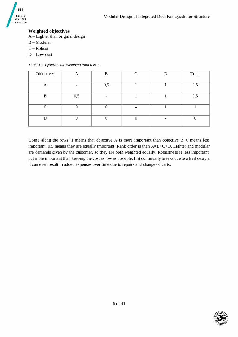
List of tables Table 1. Objectives are weighted from 0 to 1. ........................................................................................ 6
Table 2. Overview of chosen concepts and features. .............................................................................. 7
Table 3. Evaluation of concepts. ............................................................................................................. 7
Table 4. Deflections from the stiffness test. .......................................................................................... 10
Table 5. Materials selection criteria for duct. ........................................................................................ 17
Table 6. Densities of the materials given in CES. ................................................................................. 21
Table 7. Materials selection criteria for support ring. ........................................................................... 22
List of Figures Figure 1. Duct fan solution [1]. ............................................................................................................... 1
Figure 2. Balakrishnan's duct design [1]. ................................................................................................ 3
Figure 3. Stiffness test, deflection [2]. .................................................................................................... 4
Figure 4. Concept A, B and C. ................................................................................................................ 5
Figure 5. Final 3D print design. .............................................................................................................. 8
Figure 6. Cross section view and illustration of nut solution. ................................................................. 9
Figure 7. DJI Flame Wheel F450 arm. .................................................................................................. 10
Figure 8. Duct with integrated arm, 3D printed. ................................................................................... 11
Figure 9. Profile of the duct with support ring and arm. ....................................................................... 13
Figure 10. Top view of the duct. ........................................................................................................... 13
Figure 11. Profile of the duct showing the slit for the support ring. ..................................................... 14
Figure 12. Final concept model. ............................................................................................................ 16
Figure 13. Side view of final concept. ................................................................................................... 16
Figure 14. E- ρ chart showing the optimal materials for a low mass stiff duct. .................................... 20
Figure 15. E- ρ chart showing the optimal materials for the support ring. ............................................ 23
Figure 16. Top cover designed by Balakrishnan. .................................................................................. 24
Figure 17. Wire mesh top cover. ........................................................................................................... 24
Figure 18. Forces acting on the ducted solution when accelerating vertically. ..................................... 25
Figure 19. Displacement on ring with PLA plastic with forces from thrust, drag and gravity forces. .. 27
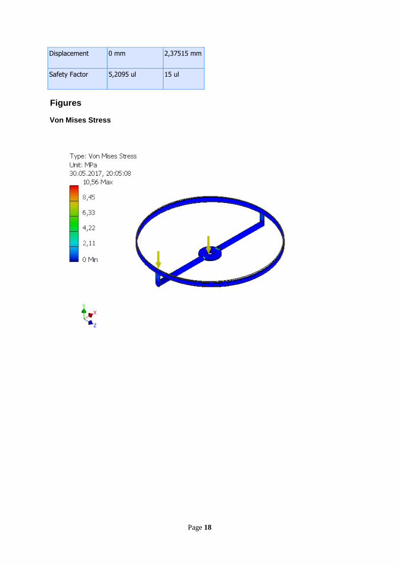
Figure 20. Von Mises Stress on ring made of PLA plastic. .................................................................. 28
Figure 21. Cross section of rod [11]. ..................................................................................................... 29
Figure 22. Cantilever beam [12]. ........................................................................................................... 29
Figure 23. Deflection due to weight from duct. .................................................................................... 30
Figure 24. Displacement on the duct. .................................................................................................... 31
Figure 25. Von Mises stress on duct. .................................................................................................... 31
Figure 26. Displacement of ring, duct and top cover. ........................................................................... 32
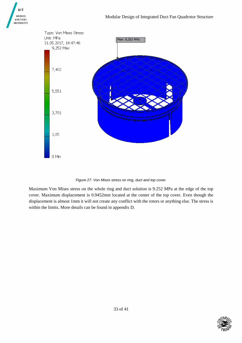
Figure 27. Von Mises stress on ring, duct and top cover. ..................................................................... 33
Figure 28. Final solution. ...................................................................................................................... 35
Figure 29.Final solution seen from underneath. .................................................................................... 36
Figure 30. Prototype in styrofoam. ........................................................................................................ 37
Figure 31. Prototype with drone arm and rotor. .................................................................................... 37

Modular Design of Integrated Duct Fan Quadrotor Structure
Abbreviations CA Cellulose Acetate
CAD Computer Assisted Design
CES Cambridge Engineering Selector
LD Low Density
MD Medium Density
RPF Rigid Polymer Foam
PA Polyamid
PCB Printed Circuit Board
PLA Polylactic Acid
RPM Revolutions Per Minute
VLD Very Low Density
UiT Universitetet I Tromsø

Modular Design of Integrated Duct Fan Quadrotor Structure
1 of 41
1 Introduction
1.1 Background This master thesis is based on the work of Sethuram Balakrishnan in his master thesis “Duct fanned
shielding design for quadrotors” from 2016 in cooperation with UiT. Balakrishnan came up with a
solution which gave thrust increase and rotor shielding for the quadrotor DJI Flame wheel F450. The
dronelab at UiT in Narvik has a goal to make the drone completely autonomous. That means it will fly
all on its own without any manual control. This leads to an increased demand for safety, both for the
drone itself and the environment. In the previous report, it has been done several simulations regarding
thrust and flow efficiency in the duct. This is the foundation for the design of the ducts. The duct fan
solution is supposed to be mounted on the DJI Flame wheel F450 quadrotor kit, and will therefor add
significant mass to the quadrotor. Even though Balakrishnan has done work regarding saving weight, it
is possible to reduce it more. This will be the main purpose of our thesis, since increased mass is highly
undesirable on a quadrotor. The material chosen by Balakrishnan for his duct fan solution is the
thermoplastic PA612-GF30 (Polyamide – Nylon). This is also the material used on the structure of the
quadrotor DJI Flame wheel F450. In addition to the duct fan solution, the concept contains a top cover
in the same material, which will protect the rotors from objects entering the rotors from above.
Tests done using thrust measuring devices show nearly 40% improvement in thrust over an un-ducted
quadrotor. The resulting weight of the duct was about 1150g. When including the added weight to the
quadrotor, the increase in thrust is about 10% compared to the un-ducted quadrotor [1]. These results
are so significant that it is interesting to continue the work. It is assumed that the weight can be lowered
even more if the duct fan is built into the quadrotor. The master thesis will therefore continue the work
of Balakrishnan and the main goal will be to reduce the mass by integrating the duct to the quadrotor
and looking into other possible materials.
Figure 1. Duct fan solution [1].
Modular Design of Integrated Duct Fan Quadrotor Structure
2 of 41
1.2 Problem description The master thesis will look into the possibility of integrating the outer structure of the quadrotor with
ducted fan solution in order to save weight. Balakrishnan’s solution combines shielding of the rotors
with increased thrust. This thesis will aim to save weight while maintaining the increased thrust
compared to a non-ducted quadrotor. The ducts should be designed modular since it is likely that
damage only occur to one duct while the others remain intact. A top cover for the ducts should also be
a part of the final design. The quadrotor used in Balakrishnan’s thesis is the DJI Flame Wheel F450, it
is therefore natural to continue with the same quadrotor for this thesis. Robustness, availability and
price are additional design criteria which we aim to fulfill, but will not be a design requirement.

Modular Design of Integrated Duct Fan Quadrotor Structure
3 of 41
2 Design process
2.1 Customer and design requirements The task has some restrictions in terms of design of the quadrotor. In order to be successful, there are a
few requirements that need to be fulfilled. These are requirements set from the customer. The most
important requirement is to keep the weight at a minimum and at the same time keep the thrust equal to
the previous solution. This will be a minimum requirement since the new concept is supposed to be an
improvement of the previous work. To keep the thrust properties equal to the previous solution the inside
of the duct needs to be approximately equivalent to the previous solution. A possibility of changing one
duct fan at the time is a requirement from the customer. The body of the quadrotor will have to be stiff.
If the structure has lack of stiffness several problems can occur, but it will most likely result in poor
flying characteristics. There will be done a test regarding stiffness on the existing arms of the DJI flame
wheel f450 quadrotor. The stiffness of a possible new frame should have approximately the same values
in order to have the desired stiffness.
Figure 2. Balakrishnan's duct design [1].
Design specification bullet points:
Lower weight
Stiff frame, with the test results as a reference
Modular ducts
Inside geometry of ducts same as Balakrishnan’s design
Low cost
Robust
Modular Design of Integrated Duct Fan Quadrotor Structure
4 of 41
The two power distribution boards are PCB (Printed circuit boards) and contain important circuits for
the electronic system of the quadrotor. It is therefore decided to keep the power distribution boards to
avoid getting into subjects beyond our field of expertise.
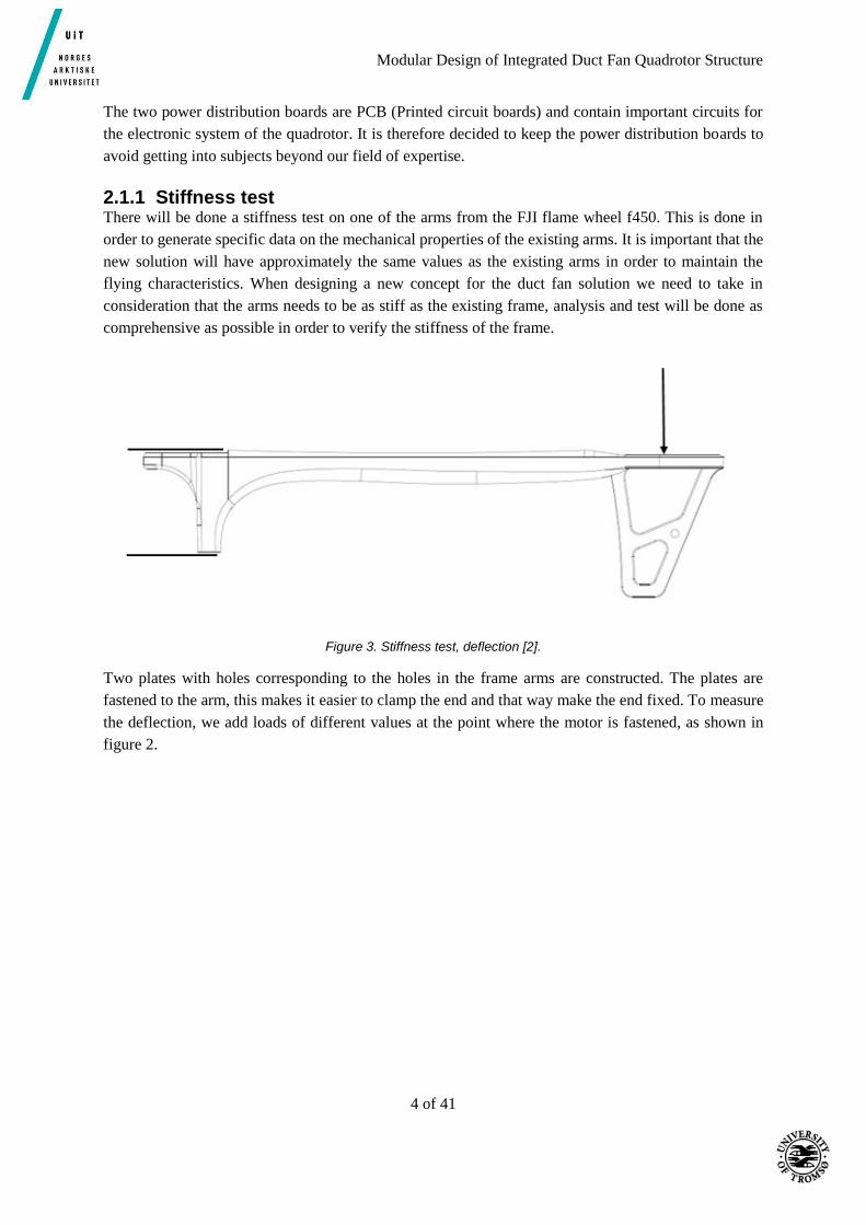
2.1.1 Stiffness test There will be done a stiffness test on one of the arms from the FJI flame wheel f450. This is done in
order to generate specific data on the mechanical properties of the existing arms. It is important that the
new solution will have approximately the same values as the existing arms in order to maintain the
flying characteristics. When designing a new concept for the duct fan solution we need to take in
consideration that the arms needs to be as stiff as the existing frame, analysis and test will be done as
comprehensive as possible in order to verify the stiffness of the frame.
Figure 3. Stiffness test, deflection [2].
Two plates with holes corresponding to the holes in the frame arms are constructed. The plates are
fastened to the arm, this makes it easier to clamp the end and that way make the end fixed. To measure
the deflection, we add loads of different values at the point where the motor is fastened, as shown in
figure 2.

Modular Design of Integrated Duct Fan Quadrotor Structure
5 of 41
2.2 Generating concepts The design requirements are not strictly defined to a certain solution, so there is a high degree of freedom
on how to solve the problem. This has led to several different concepts that vary vastly in design, but
satisfy the requirements. Several methods have been used to select the most optimal design with regards
to satisfy the requirements and available production methods and materials.
As mentioned in the design specification, the solution must be lightweight, modular and robust. Through
brainstorming and discussion, five concepts were developed.
a) Drone arms integrated in the duct
b) Shorter custom arms, duct attached to arm
c) Custom frame attached to drone, duct attached to frame
d) Monocoque of a light material
e) Ducts made of a very lightweight material attached to a stiff and robust ring on the drone arms
Concept a), b) and c) are developed especially with 3D printing as a production method in mind. This
is readily available on the UiT campus, and would be easy and close by if the dronelab need more parts
in the future. Other production methods are also possible, but 3D printing was examined first. The idea
of these three concepts is to shorten the arm on the drone, thus reducing the mass. However, it will lead
to a challenge in mounting the engine. Since the engine is mounted to the drone arm in the original
design, a shorter arm requires the engine to be mounted directly to the duct. Testing and analysis is
required to find out if the duct is strong enough to support the added load of directly supporting the
engine.
Figure 4. Concept A, B and C.
Concept d) would forego arms all together, instead supporting the duct and engines in a monocoque
body of a lightweight material. After discussion and evaluation, it was deemed not modular enough to
fulfil the customers wishes.
Concept e) would have a robust ring attached to the drone arms which would support the ducts made of
a lightweight material such as Styrofoam or something similar. In the original design, most of the mass
was in the ducts themselves, so by reducing this mass a large percentage of the total mass would be
reduced. The duct will not be as robust as with a plastic material, but the ring will provide some
protection against collision, and the foam material will absorb a lot of forces. If it breaks it will be easy
and cost efficient to replace.
Modular Design of Integrated Duct Fan Quadrotor Structure
6 of 41
Weighted objectives A – Lighter than original design
B – Modular
C – Robust
D – Low cost
Table 1. Objectives are weighted from 0 to 1.
Objectives A B C D Total
A - 0,5 1 1 2,5
B 0,5 - 1 1 2,5
C 0 0 - 1 1
D 0 0 0 - 0
Going along the rows, 1 means that objective A is more important than objective B. 0 means less
important. 0,5 means they are equally important. Rank order is then A=B>C>D. Lighter and modular
are demands given by the customer, so they are both weighted equally. Robustness is less important,
but more important than keeping the cost as low as possible. If it continually breaks due to a frail design,
it can even result in added expenses over time due to repairs and change of parts.

Modular Design of Integrated Duct Fan Quadrotor Structure
7 of 41
Morphological chart Table 2. Overview of chosen concepts and features.
The green line shows the concepts that was chosen. On the custom arm feature, the original arm was
chosen, so the green line ends up on a blank box.
Evaluation matrix Table 3. Evaluation of concepts.
Selection criteria
Concepts
A
Duct with integrated arm
B
Custom arm short
C
Custom frame
D
Monocoque design
E
Super light duct
Lightweight + + + + +
Modular + + + 0 +
Robust 0 0 0 + 0
Production method
0 0 0 0 +
Sum +'s 2 2 2 2 3
Sum 0's 2 2 2 2 1
Sum -'s 0 0 0 0 0
Net score 2 2 2 2 3
Rank 2 3 4 5 1
The evaluation matrix compare the concepts to Balakrishnan’s original design with regards to the
design requirements and production method. [2]

Modular Design of Integrated Duct Fan Quadrotor Structure
8 of 41
2.3 Rapid prototyping The requirements set from the customer does not say anything about production or material, which
means we are free to choose the best material regardless of production method. Even though, it feels
natural to consider a 3D printing design because of its advantages in manufacturing and the access to
3D printers at UiT. An equivalent solution could be made lighter and stiffer with another material, but
when having a 3D printer available it is natural to consider a 3D printed solution as an alternative. When
generating alternatives for 3D printing, there was a few limitations. The main limitation is the size of
the 3D printer at UiT. We have access to a 290x290cm 3D printer. This means that it is not possible to
3D print the whole duct fan solution of Balakrishnan. It is also hard to calculate the mechanical
properties of a 3D printed constructions because of the material which is constructed in layers and
therefor has different properties in various directions. It will be done tests regarding stiffness on the final
3D printing solution to see if it is realistic to use it. The results will be compared with results from the
stiffness test of the DJI flame wheel f450 arms.
After a design process, a few alternatives were generated. Throughout the process we were assisted from
one of the persons with experience in 3D printing at the university. Together a concept was selected and
printed in order to investigate the possibility of using a 3D printed solution as an alternative.
Figure 5. Final 3D print design.
Modular Design of Integrated Duct Fan Quadrotor Structure
9 of 41
2.3.1 Specifications The 3D printed solution is a modified version of the previous duct design. It is added a structure to fix
the duct to the power distribution boards directly. This is a solution with a shortened custom arm as
mentioned in chapter 2.2. In addition to the shortened arm attached to the duct the structure is reinforced
with two arms pointing 45 degrees out from the normal arm. This can be seen on figure 5. The arms are
designed in a framework in order to save weight. The crossbeam inside the duct has been slightly
modified to be structurally stiffer. It used to be hollow, but in order to achieve desired stiffness it’s been
made solid. Also, the cross section of the beam has been slightly changed to avoid too much deflection.
It has been modified from a circle to an ellipse with greater diameter in the up-down direction. The
original arm has threads to bolt the PCB to the arm. Because of the challenges of making threads when
3D printing another solution had to be made. The solution to this is to use nuts instead of threads in the
arm. Ideal one could have used one bolt through the whole arm with a nut on the bottom to fasten both
PCBs, this is not possible because the holes on the top and bottom of the PCB are slightly offset.
Therefor a solution with square nuts inside the construction is made, this will allow the PCBs to be
fastened without affecting the structure significantly. This solution will however need different bolts
than the original. The original quadrotor uses M2.5x5mm bolts, this design will require longer bolts,
preferably M2.5x15mm [3].
The material used in the 3D printed version is PLA plastic, it has a tensile strength between 30 and 40
MPa. Printing of the model were made with four layers as a maximum. This means that the 3D printer
makes four layers with solid material and if a structure is thicker it compensates with making a
honeycomb core. Practically for our model this means that the crossbeam is not solid, as we made it,
but has a honeycomb structure inside. Total weight of the 3D printed version is 238.7g, this gives a total
weigh for four ducts at 954.8g. This reduces the weight of the duct solution significantly. Balakrishnan's
solution’s mass is 1150g, when including the drone arms the total mass is 1366g not including top cover
[1] [3]. In our design the original arms are not used so the total weight saving is 1366g – 954.8g+80g =
500.2g (including top cover). This is a weight saving of about a third of the previous solution for ducts,
top cover and arms.
Figure 6. Cross section view and illustration of nut solution.

Modular Design of Integrated Duct Fan Quadrotor Structure
10 of 41
The main advantage of a 3D printed solution is that the production is relatively easy for the customer
which have access to the 3D printer at UiT. There are some disadvantages with the design, primarily
that it is considerably heavier than other solutions. The inaccuracy of the 3D print makes the nut solution
not practical, the support structure from rapid prototyping blocks the hole and is difficult to remove.
When evaluating concepts these pros and cons will have to be evaluated against each other. The
customer will also give their opinion on what is weighted as more important.
2.3.2 Stiffness test of 3D printed solution and original arm To investigate the stiffness of the 3D printed solution and the original DJI flame wheel F450 arm a
stiffness test was performed. The process is described in part 2.1.1. Weight loads of different sizes were
added to where the rotor is mounted and then deflection was measured. Weight loads of 500g and 2500g
were used. Different measuring methods was used to ensure that the results were right. Results from the
test show that the 3D printed solution has approximately the same stiffness for loads applied at the rotors
mounting place.
Table 4. Deflections from the stiffness test.
Weight load Original arm (mm) 3D printed solution (mm)
Method 1, 500g 1.77 1.77
Method 2, 500g 1.68 1.68
Method 1, 2500g 8.65 8.67
Method 3, 2500g 12 11
Figure 7. DJI Flame Wheel F450 arm.

Modular Design of Integrated Duct Fan Quadrotor Structure
11 of 41
Figure 8. Duct with integrated arm, 3D printed.

Modular Design of Integrated Duct Fan Quadrotor Structure
12 of 41
3 Final design After evaluation and meetings with the customer, concept E was chosen for the final design. Concept E
had the highest potential for a large reduction in total mass, it is 100% modular, easily manufactured
and the cheapest. A prototype of concept A was manufactured for testing as a viable solution. A full-
scale model of the duct with an integrated arm was 3D printed, but unfortunately there was not enough
of a reduction in mass compared to concept E. The production method was simple, but time consuming
and the cost was about the same as Balakrishnan’s original design. There would also be challenges
related to the structural integrity of the integrated arm since the stabilizing rod would need to carry the
entire load of the engine and related forces. Concept B and C suffered from the same drawbacks as
concept A. Roughly the same cost, a very small reduction in mass and poorer structural integrity.
Concept D was deemed not modular enough to fulfill the design requirements.

Modular Design of Integrated Duct Fan Quadrotor Structure
13 of 41
3.1 Early sketches Early sketches of the final design.
Figure 9. Profile of the duct with support ring and arm.
Figure 10. Top view of the duct.

Modular Design of Integrated Duct Fan Quadrotor Structure
14 of 41
Figure 11. Profile of the duct showing the slit for the support ring.
3.2 Evaluation of different solutions Two alternatives were discussed as possibilities for concept E. One where the original arm was kept,
with a support ring mounted on top of the arm, and the duct placed inside the ring. The other would be
a completely new custom arm with the support ring mounted on the edge of the arm, resulting in a
shorter arm. The group decided to keep the original arm. This was the easiest solution, and would be a
very robust and lightweight construction, keeping the stiffness of the original arm. The arm would carry
most of the load compared to the shorter arm where the ring would carry most of the load.
Calculations were done with values from Balakrishnan’s thrust testing regarding flight time of some of
the different concepts. See table C-1 in appendix C for thrust values at different RPM, and external
appendix F (preliminary work) about formulas regarding flight time.
Thrust (N) Power (W) G
(mass * G)/4 prop. const. * rpm^power factor/1000 9,81
Mass (kg)
Balakrishnan 1,15
Integrated duct 0,955
Original drone 0,8
Thrust Balakrishnan 4,78
Thrust original 1,96
Thrust integrated 4,30
Thrust needed for test 3,9
Flight time (min) Battery capacity/Ampere used*60min
Balakrishnan 12,78
Original 18,5
Integrated 18,5
Test 28,29

Modular Design of Integrated Duct Fan Quadrotor Structure
15 of 41
Propeller constant Power factor
0,136 3,4
Power (W)
Power bala 36,47
Power original 25,18
Power integrated 25,18
Power Test 16,48
Ampere (A) I=P/V
Ampere Balakrishnan 13,14
Ampere original 9,07
Ampere integrated 9,07
Ampere test 5,94
Volt Battery capacity (Ah)
11,1 2,8
RPM/1000
Balakrishnan 5,179
Original 4,644
Integrated 4,644
Test 4,1
4100 rpm gives a thrust of 3,9N
The mass needed to reach this will then be
T*4/G 1,59 kg Mass of the design must be less than 1590g-800g=790g
This gave a frame of reference for the total mass of the design. If the mass is kept under 790g, then only
3,9N of thrust is needed for the drone to hover. And this will result in a flight time of about 28min,
which is a 10min improvement over the original design of the drone, and a 16min improvement over
Balakrishnan’s design [4].
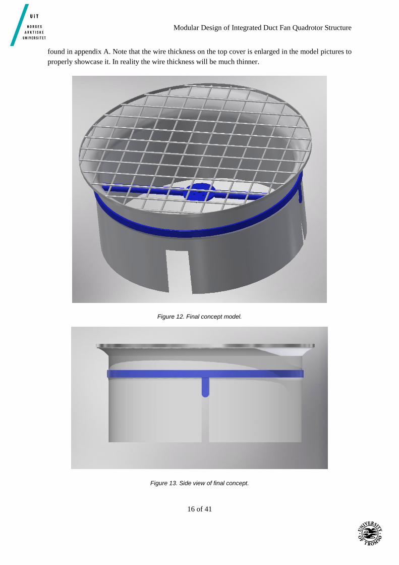
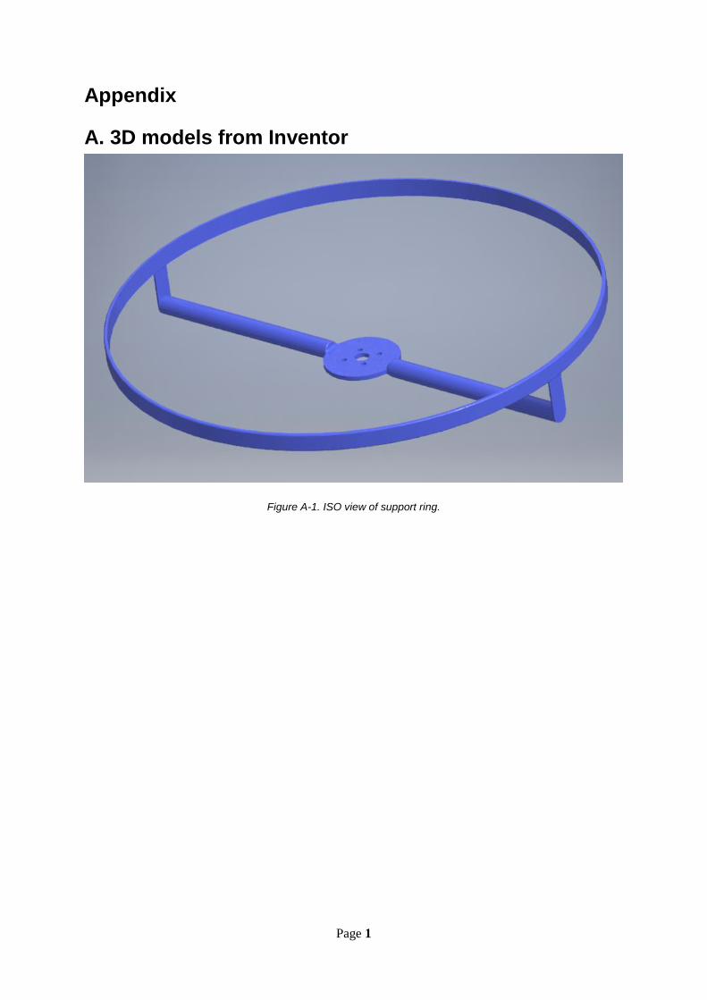
3.3 3D model The model consists of 3 parts, the support ring mounted on the drone arm, the duct placed inside the
support ring, and the top cover placed on top of the duct. The support ring has a stabilizing rod with a
mounting platform in the middle with holes corresponding to the mounting holes on the drone arm and
engines. The mounting platform will be placed between the arm and engine. The duct is then mounted
inside the ring. Slits on the sides are for the stabilizing rod, and the big slit in the front is for the drone
arm. On the outside of the duct there is an edge for the support ring. This will help to secure the duct in
place inside the ring, but will allow the duct to be removed. More pictures of individual parts can be
Modular Design of Integrated Duct Fan Quadrotor Structure
16 of 41
found in appendix A. Note that the wire thickness on the top cover is enlarged in the model pictures to
properly showcase it. In reality the wire thickness will be much thinner.
Figure 12. Final concept model.
Figure 13. Side view of final concept.

Modular Design of Integrated Duct Fan Quadrotor Structure
17 of 41
4 Materials selection
4.1 Duct For this analysis, the duct was regarded as a plate loaded with a bending force. It is simplified, but as
Ashby says, “The simplification is rarely as critical as it may at first
appear: the choice of material is determined primarily by the physical principles of the problem, not by
details of geometry” [5].
Table 5. Materials selection criteria for duct.
The plates objective function is:
𝑚 = 𝐴𝜌𝑙 (1)
Where,
A = the area of the duct (m2)
𝑙 = the length of the plate (m)
𝜌 = Density of the material (kg/m3)
𝐴𝑟𝑒𝑎 = 𝑏 ∗ 𝑡 (2)
𝐵𝑒𝑛𝑑𝑖𝑛𝑔 𝑠𝑡𝑖𝑓𝑓𝑛𝑒𝑠𝑠 𝑆 =
𝐹
𝛿
(3)
Where,
𝑏 = 𝑤𝑖𝑑𝑡ℎ 𝑜𝑓 𝑡ℎ𝑒 𝑝𝑙𝑎𝑡𝑒
𝑡 = 𝑡ℎ𝑖𝑐𝑘𝑛𝑒𝑠𝑠 𝑜𝑓 𝑡ℎ𝑒 𝑝𝑙𝑎𝑡𝑒
Function: Protect propeller and direct airflow
Constraints: Radius R specified
δ must not exceed the value from the test
Objective: Minimize the mass m
Free
variable:
Choice of material
.

Modular Design of Integrated Duct Fan Quadrotor Structure
18 of 41
𝐹 = 𝑓𝑜𝑟𝑐𝑒 𝑎𝑝𝑝𝑙𝑖𝑒𝑑
𝛿 = 𝐷𝑒𝑓𝑙𝑒𝑐𝑡𝑖𝑜𝑛 𝑜𝑓 𝑡ℎ𝑒 𝑝𝑙𝑎𝑡𝑒 𝑑𝑢𝑒 𝑡𝑜 𝑡ℎ𝑒 𝑓𝑜𝑟𝑐𝑒
Deflection of the plate is given by,
𝛿 =𝐹 ∗ 𝑙3
𝐶1 ∗ 𝐸 ∗ 𝐼
(4)
Where,
𝐼 = 𝑆𝑒𝑐𝑜𝑛𝑑 𝑚𝑜𝑚𝑒𝑛𝑡 𝑜𝑓 𝑖𝑛𝑒𝑟𝑡𝑖𝑎
𝐸 = 𝑌𝑜𝑢𝑛𝑔′𝑠 𝑚𝑜𝑑𝑢𝑙𝑢𝑠
𝐶1 = 𝐴 𝑐𝑜𝑛𝑠𝑡𝑎𝑛𝑡 𝑡ℎ𝑎𝑡 𝑑𝑒𝑝𝑒𝑛𝑑𝑠 𝑜𝑛 𝑡ℎ𝑒 𝑑𝑖𝑠𝑡𝑟𝑖𝑏𝑢𝑡𝑖𝑜𝑛 𝑜𝑓 𝑙𝑜𝑎𝑑𝑠
Inserting this into bending stiffness,
𝑆 =𝐹
𝐹 ∗ 𝑙3
𝐶1 ∗ 𝐸 ∗ 𝐼
𝑆 =𝐶1 ∗ 𝐸 ∗ 𝐼
𝑙3
𝐼 =𝑏𝑡3
12
Inserting I into bending stiffness,
𝑆 =𝐶1∗𝐸∗(
𝑏𝑡3
12)
𝑙3
𝑆 =𝐶1∗𝐸∗𝑏∗𝑡3
𝑙3∗12
𝑆 =𝐶1∗𝐸∗𝑏
12(
𝑡3
𝑙3)
𝑡
𝑙= (
12∗𝑆
𝐶1∗𝐸∗𝑏)
1
3
Modular Design of Integrated Duct Fan Quadrotor Structure
19 of 41
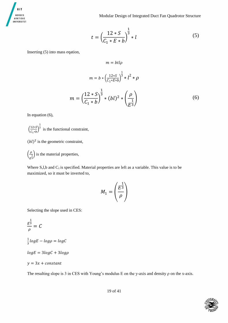
𝑡 = (12 ∗ 𝑆
𝐶1 ∗ 𝐸 ∗ 𝑏)
13
∗ 𝑙 (5)
Inserting (5) into mass eqation,
𝑚 = 𝑏𝑡𝑙𝜌
𝑚 = 𝑏 ∗ (12∗𝑆
𝐶1∗𝐸∗𝑏)
13
∗ 𝑙2
∗ 𝜌
𝑚 = (12 ∗ 𝑆
𝐶1 ∗ 𝑏)
13
∗ (𝑏𝑙)2 ∗ (𝜌
𝐸13
) (6)
In equation (6),
(12∗𝑆
𝐶1∗𝑏)
1
3 is the functional constraint,
(𝑏𝑙)2 is the geometric constraint,
(𝜌
𝐸13
) is the material properties,
Where S,l,b and C1 is specified. Material properties are left as a variable. This value is to be
maximized, so it must be inverted to,
𝑀1 = (𝐸
13
𝜌)
Selecting the slope used in CES:
𝐸13
𝜌= 𝐶
1
3𝑙𝑜𝑔𝐸 − 𝑙𝑜𝑔𝜌 = 𝑙𝑜𝑔𝐶
𝑙𝑜𝑔𝐸 = 3𝑙𝑜𝑔𝐶 + 3𝑙𝑜𝑔𝜌
𝑦 = 3𝑥 + 𝑐𝑜𝑛𝑠𝑡𝑎𝑛𝑡
The resulting slope is 3 in CES with Young’s modulus E on the y-axis and density ρ on the x-axis.
Modular Design of Integrated Duct Fan Quadrotor Structure
20 of 41
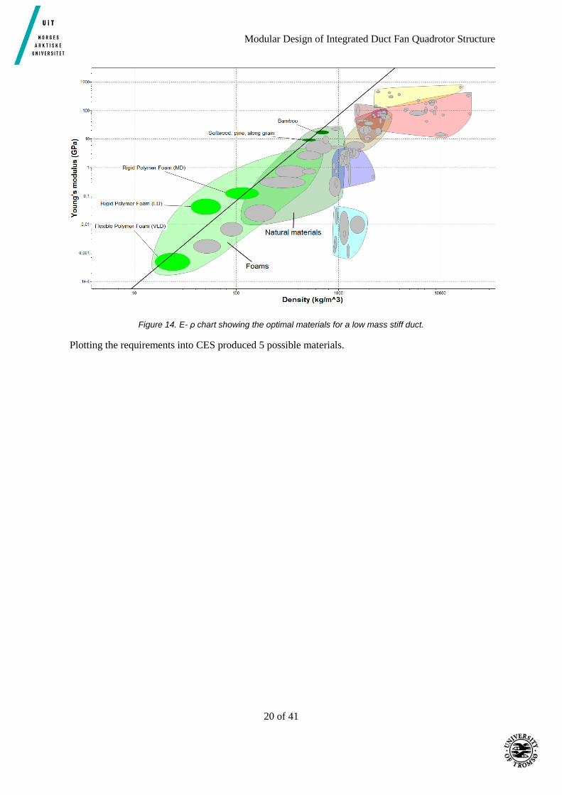
Figure 14. E- ρ chart showing the optimal materials for a low mass stiff duct.
Plotting the requirements into CES produced 5 possible materials.

Modular Design of Integrated Duct Fan Quadrotor Structure
21 of 41
Table 6. Densities of the materials given in CES.
Material Density (kg/m3)
Flexible Polymer foam (VLD) 16-35
Rigid Polymer Foam (LD) 36-70
Rigid Polymer foam (MD) 78-165
Softwood: Pine, along grain 440-600
Bamboo 600-800
As mentioned in chapter 3.2, the aim is to have a mass less than 790g. Using the volume of the design
given in inventor, some calculations were done with the different densities of the materials from CES.
𝑉 = 405088,066𝑚𝑚3 = 0,000405𝑚3
𝑚1 = 𝑉𝜌1 = 0,000405𝑚3 ∗ 16𝑘𝑔/𝑚3 = 0,00648𝑘𝑔 = 6,5𝑔
𝑚2 = 𝑉𝜌2 = 0,000405 ∗ 36𝑘𝑔/𝑚3 = 0,01458𝑘𝑔 = 14,6𝑔
𝑚3 = 𝑉𝜌3 = 0,000405 ∗ 70𝑘𝑔/𝑚3 = 0,02835𝑘𝑔 = 28,4𝑔
𝑚4 = 𝑉𝜌4 = 0,000405 ∗ 165𝑘𝑔/𝑚3 = 0,066825𝑘𝑔 = 66,8𝑔
𝑚5 = 𝑉𝜌5 = 0,000405 ∗ 440𝑘𝑔/𝑚3 = 0,1782𝑘𝑔 = 178,2𝑔
These calculations are for 1 duct, so with 4 it is a total of,
𝑚1 = 26𝑔
𝑚2 = 58,3𝑔
𝑚3 = 113,4𝑔
𝑚4 = 267,3𝑔
𝑚5 = 712,8𝑔
This rules out everything above 440kg/m3 since this mass is getting close to 790g, and the mass of the
support ring and top cover is still to be added. This also gives some leeway to make changes to design
if needed.

Modular Design of Integrated Duct Fan Quadrotor Structure
22 of 41
To help choose between the different materials, limits were added. A strong material would be best
suited so that the duct would not buckle or deform under load and damage the propeller.
Flexible polymer foam has a very low Young’s modulus (<0,001GPa), and is usually used for cushions,
mattresses and shock absorption in packaging. As the name suggests, since it is flexible, it is not stiff
enough to serve as the duct. Low density rigid polymer foam (RPF) is very lightweight and solid. It is
commonly used for isolation in buildings. It would be possible to use it as a duct, but it is very fragile.
Medium density RPF is very lightweight and has just enough structural integrity to serve as a modular
lightweight duct. It is used for disposable thermally insulating cups, lightweight structural use and as
the core in sandwich panels. High density RPF is too dense for this project, and will add too much mass
the duct. Since the design is relying on the outer ring for protection and the duct is only directing the
air, the duct can be allowed to be weaker. Medium density RPF is strong enough to direct air and
lightweight enough for this design. It is easily manufactured and comes in all shapes and sizes. Liquid
raw polymer materials are poured into a paper mold where it foams and takes the shape of the mold. It
is then stored for a day to cure the foam and cool. After it is cured, the blocks can be cut into whatever
shape needed [6].
4.2 Support ring The ring will provide some shielding for the propeller and duct and is placed in propeller height on the
outside of the duct so it can absorb forces that would otherwise hit the propeller in a crash or similar
circumstances. It has the same requirements as the duct, except it needs to be stronger to support the
duct and shield against external loads.
Table 7. Materials selection criteria for support ring.
Function Support and protect the duct
Constraints Inner radius r is specified
Ring must not buckle
Stabilizing rod must be stiff
Objective Minimize mass
Free
variable
Material
The first material index that was maximized was the same as for the duct.
𝑀1 = (𝐸
13
𝜌)
Another index was added, since the ring needed to withstand some forces and provide some protection.
The index 𝑀1 = (𝜎𝑦
12
𝜌) and 𝑀1 = (
𝐸12
𝐶) was maximized as well. This did not reduce the amount of
Modular Design of Integrated Duct Fan Quadrotor Structure
23 of 41
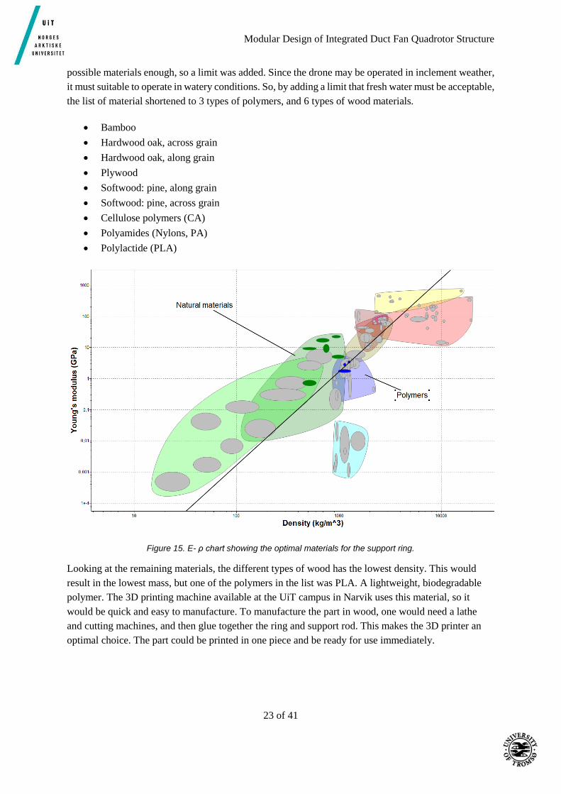
possible materials enough, so a limit was added. Since the drone may be operated in inclement weather,
it must suitable to operate in watery conditions. So, by adding a limit that fresh water must be acceptable,
the list of material shortened to 3 types of polymers, and 6 types of wood materials.
Bamboo
Hardwood oak, across grain
Hardwood oak, along grain
Plywood
Softwood: pine, along grain
Softwood: pine, across grain
Cellulose polymers (CA)
Polyamides (Nylons, PA)
Polylactide (PLA)
Figure 15. E- ρ chart showing the optimal materials for the support ring.
Looking at the remaining materials, the different types of wood has the lowest density. This would
result in the lowest mass, but one of the polymers in the list was PLA. A lightweight, biodegradable
polymer. The 3D printing machine available at the UiT campus in Narvik uses this material, so it
would be quick and easy to manufacture. To manufacture the part in wood, one would need a lathe
and cutting machines, and then glue together the ring and support rod. This makes the 3D printer an
optimal choice. The part could be printed in one piece and be ready for use immediately.

Modular Design of Integrated Duct Fan Quadrotor Structure
24 of 41
4.3 Top cover The top cover share many of the same requirements as the duct itself. It must be lightweight, robust,
modular and not hinder the airflow through the duct. A very fine mesh is therefore to be avoided. Two
concepts were evaluated.
Concept A:
Balakrishnan’s ribbed top cover. Large holes as to not hinder airflow, low mass and cost. Fastened by
pressing it over the edge of the duct. Fastening method not suited for this design when the duct is
made of rigid polymer foam.
Figure 16. Top cover designed by Balakrishnan.
Concept B:
Wire mesh cover with a large mesh size. Fastened with an elastic band over the edge of the duct.
Balakrishnan’s design was discarded in favor of a more suitable top cover. A wire mesh cover with a
large mesh size and thin wires in aluminum fastened with an elastic band over the duct. The tapered
shape of the duct will keep the elastic band down and the top cover in place on top of the duct. The
size of the mesh will be small compared to the ribbed top cover, but will still be large enough as to not
interfere with the airflow.
Figure 17. Wire mesh top cover.

Modular Design of Integrated Duct Fan Quadrotor Structure
25 of 41
5 Main results from numerical computations The focus of the analysis will be on structural computations. Balakrishnan has already done
computations regarding flow and thrust in his report and since there are only small changes on the inside
of the duct there will not be done any computations or simulations related to this. The simulations will
concentrate on structural strength of components in order to make the design as strong and stiff as
preferred. The parts that will undergo numerical and analytical computations are the ring structure and
the duct. There will be done structural simulations and analytical computations on the ring design and
structural simulations on the duct. Results will be used to verify that the materials can withstand the
forces and discover weaknesses in the structure. Numerical analysis is done with the Stress Analysis
feature in Autodesk Inventor. Details about the simulation and the stress analysis setup can be found in
appendix.
5.1 Analysis of ring In order to run simulations it is necessary to find the maximal forces applied to ring. In normal
circumstances this will be when the quadrotor accelerates as fast as possible based on Newton’s second
law of motion, 𝐹 = 𝑚𝑎. To simplify the simulation we look at forces acting in vertical direction. The
quadrotor will be exposed to maximum forces when the thrust is at its highest. The maximum thrust for
the quadrotor with ducted rotors is 9.1537N [1]. It is not stated how fast the Flame Wheel f450 can
accelerate vertical so we do some calculations to achieve a number to work from.
Figure 18. Forces acting on the ducted solution when accelerating vertically.
Figure 8 illustrates forces acting on the solution, T is the force generated from thrust, D is the drag from
air resistance and G is the force from gravity. We know the maximal thrust generated by one rotor, this
gives a total force of

Modular Design of Integrated Duct Fan Quadrotor Structure
26 of 41
𝑇 = 9.1537𝑁×4 = 36.615 𝑁 (7)
The total weight of the drone, with the minimum takeoff weight of 800g [3] becomes
𝑚 = 1.33 𝑘𝑔
from this we calculate G
𝐺 = 9.81𝑚
𝑠2×1.33𝑘𝑔 = 13.05𝑁 (8)
We can calculate drag from the drag equation [7]
𝐷 = 𝐶𝑑 ⋅
𝜌 ⋅ 𝑉2
2⋅ 𝐴 (9)
were 𝐶𝑑 is a drag coefficient that varies with the shape of the object. In our case we define the quadrotor
as a flat plate and get a drag coefficient of 1.28 [8]. 𝜌 is the density of air which is 1.225 𝑘𝑔/𝑚3 at
150𝐶 [9]. The drone’s top vertical velocity is 6𝑚
𝑠, we therefor set the velocity 𝑉 to 6
𝑚
𝑠. We do an
approximation on the surface of the quadrotor and define the area A as the area created from the edges
of the quadrotor. With these values and approximations the drag equation (9) can be solved.
D = 1.28 ⋅ 1.225
kg
m3⋅ (6
m
s2) ⋅
0.1318 m2
2= 3.72 N
From equation 7, 8 and 9 the total force acting on the quadrotor then becomes
𝐹 = 𝑇 − 𝐷 − 𝐺 = 36.615𝑁 − 13.05𝑁 − 3.72𝑁 = 19.845𝑁
Use Newton’s second law of motion and calculate the vertical acceleration of the quadrotor
𝐹 = 𝑚𝑎 = 19.845𝑁
𝑎 =𝐹
𝑚=
19.845𝑁
1.33𝑘𝑔= 14.92
𝑚
𝑠2 (10)
From equation 10 we see that the acceleration the quadrotor will have is 14.92𝑚
𝑠2. We see clearly that
this is not a realistic number, the acceleration is way too high to be realistic for this quadrotor. This is
probably due to a very light takeoff weight. We have used Balakrishnan’s results from thrust testing as
a basis for the calculations and it is possible that these results are unrealistic when using the quadrotor
properly. Even though the numbers are not realistic we use them for simulations, the numbers are too
high and will give us a natural safety factor. The mass of the quadrotor is based on weight of the
quadrotor, duct, ring and top cover at an early stage in the process. It is therefore possible that the final
weight of the ducted solution will be slightly different from the mass used in the simulations.
Modular Design of Integrated Duct Fan Quadrotor Structure
27 of 41
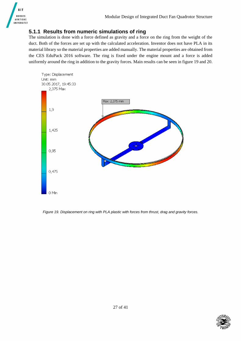
5.1.1 Results from numeric simulations of ring The simulation is done with a force defined as gravity and a force on the ring from the weight of the
duct. Both of the forces are set up with the calculated acceleration. Inventor does not have PLA in its
material library so the material properties are added manually. The material properties are obtained from
the CES EduPack 2016 software. The ring is fixed under the engine mount and a force is added
uniformly around the ring in addition to the gravity forces. Main results can be seen in figure 19 and 20.
Figure 19. Displacement on ring with PLA plastic with forces from thrust, drag and gravity forces.

Modular Design of Integrated Duct Fan Quadrotor Structure
28 of 41
Figure 20. Von Mises Stress on ring made of PLA plastic.
Maximum deflection on the ring is 2.375mm. Maximum equivalent stress is 10.56 MPa. The results are
satisfying regarding the mechanical properties of PLA. More details about the results can be found in
appendix D.
5.1.2 Analytical calculation of ring A calculation of deflection at the rods on the ring is done. Since the ring is symmetric we can look at
one of the rods out from the motor mount at the time. The structure is simplified to a cantilever beam
with a force at one end and fixed in the other end. The calculations are done to verify that the numerical
simulations are correct. The beam deflection formula for cantilever beams are given in equation 11.
Further the second moment of area for a thin walled cylinder is given in equation 12 [10] and the
dimensions are shown in figure 21. To make the calculations as similar to the stress analysis in Inventor
we use the same material properties as the numerical analysis. The calculations are done with the
properties of PLA plastic. The force F corresponds to the mass of one duct.

Modular Design of Integrated Duct Fan Quadrotor Structure
29 of 41
Figure 21. Cross section of rod [11].
Figure 22. Cantilever beam [12].
𝑢 =
𝐹𝐿3
3𝐸𝐼 (11)
𝐼 =𝜋
64(𝑑𝑦
4 − 𝑑𝑖4) (12)
𝐹 = 0.701𝑁
𝐸 = 2.2 ⋅ 109𝑃𝑎
𝑑𝑦 = 0.01𝑚, 𝑑𝑖 = 0.009𝑚, 𝐿 = 0.109𝑚
𝑢𝑚𝑎𝑥. =
0.701 ⋅ 0.1093
3 ⋅ 2.2 ⋅ 109 ⋅𝜋
64 (0.014 − 0.009)4= 8.15 ⋅ 10−4𝑚
Modular Design of Integrated Duct Fan Quadrotor Structure
30 of 41
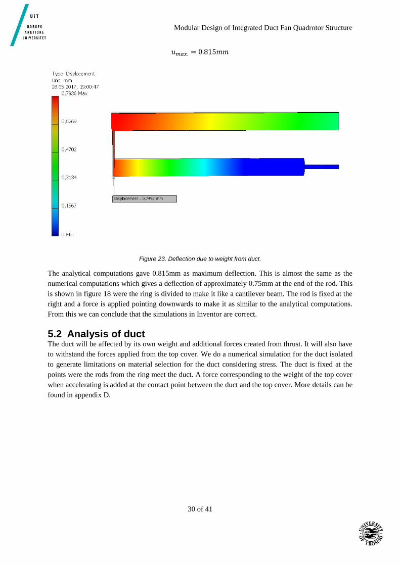
𝑢𝑚𝑎𝑥. = 0.815𝑚𝑚
Figure 23. Deflection due to weight from duct.
The analytical computations gave 0.815mm as maximum deflection. This is almost the same as the
numerical computations which gives a deflection of approximately 0.75mm at the end of the rod. This
is shown in figure 18 were the ring is divided to make it like a cantilever beam. The rod is fixed at the
right and a force is applied pointing downwards to make it as similar to the analytical computations.
From this we can conclude that the simulations in Inventor are correct.
5.2 Analysis of duct The duct will be affected by its own weight and additional forces created from thrust. It will also have
to withstand the forces applied from the top cover. We do a numerical simulation for the duct isolated
to generate limitations on material selection for the duct considering stress. The duct is fixed at the
points were the rods from the ring meet the duct. A force corresponding to the weight of the top cover
when accelerating is added at the contact point between the duct and the top cover. More details can be
found in appendix D.

Modular Design of Integrated Duct Fan Quadrotor Structure
31 of 41
5.2.1 Results from numerical simulation of duct
Figure 24. Displacement on the duct.
Figure 25. Von Mises stress on duct.

Modular Design of Integrated Duct Fan Quadrotor Structure
32 of 41
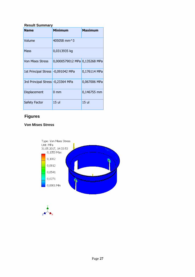
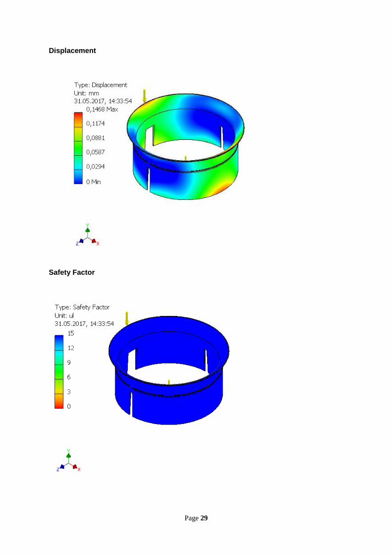
Maximum Von Mises equivalent stress is approximately 0.14 MPa. Maximum deflection is 0.15mm.
The results are within the mechanical limits of rigid polymer foam. More detail can be found in
appendix D.
5.3 Simulation of whole duct structure The whole assembly is simulated with the acceleration calculated in section 5.1. It is fixed were the
quadrotor arm is fastened. Inventor generates the contact between the different parts. More details
about the simulation can be found in appendix D.
Figure 26. Displacement of ring, duct and top cover.
Modular Design of Integrated Duct Fan Quadrotor Structure
33 of 41
Figure 27. Von Mises stress on ring, duct and top cover.
Maximum Von Mises stress on the whole ring and duct solution is 9.252 MPa at the edge of the top
cover. Maximum displacement is 0.9452mm located at the center of the top cover. Even though the
displacement is almost 1mm it will not create any conflict with the rotors or anything else. The stress is
within the limits. More details can be found in appendix D.

Modular Design of Integrated Duct Fan Quadrotor Structure
34 of 41
6 Results and discussion The final design of the duct fan solution has significant reduction in weight compared to Balakrishnan’s
solution. We have come to a solution where the ducted fan is not integrated in the quadrotor structure.
This is done because of various reasons, but mainly because in that way we keep the properties of the
frame arm which is optimized for the quadrotor. Without any physical tests, it would be difficult to
determine properties like the arms ability to transfer vibrations through the frame which could cause the
quadrotor to vibrate while flying. This will most likely affect the flying characteristics. Our design
includes three main parts, duct made of medium density RPF, a ring made of PLA and top cover in
aluminum. In addition, an attachment solution for the top cover containing an elastic band that holds the
top cover in place. This is illustrated in the CAD model. When discussing the possibility of saving
weight, the idea of having a duct which was not a part of the supporting structure came up. This gave
us the opportunity of using a very light material on the duct. The idea was that the duct only had the
purpose of providing increased thrust, the propeller shielding should be done by a smaller structure
which also held the duct in place. This became the ring structure. The top cover is designed as a wire
mesh, this would offer better protection to the propeller than the previous solution. One of the design
requirements were that the solution should be modular. In the final design the three main parts are all
modular. The duct is most likely to be damaged as this is the most fragile part. The ring is more
structurally solid and is made to protect the rotors, but if subjected to a more powerful impact the ring
will most likely be damaged. It will take a greater force to damage the top cover so this part is not likely
to be damaged.
The mass of the duct and ring are obtained from Inventor. The density of the material is manually entered
due to inequality between properties in Inventor and CES and lack of the material in the Inventor
material library. The mass of the top cover is obtained from a producer of wire mesh [13].
Mass Density
𝑚𝑑𝑢𝑐𝑡 = 66.825𝑔 ρ = 165𝑘𝑔/𝑚3
𝑚𝑟𝑖𝑛𝑔 = 33𝑔 ρ = 1240kg/m3
𝑚𝑡𝑜𝑝 𝑐𝑜𝑣𝑒𝑟 = 61.5𝑔 ρ = 2700kg/m3
The total weight of the of the ducted fan structure will be
𝑚 = (𝑚𝑑𝑢𝑐𝑡 + 𝑚𝑟𝑖𝑛𝑔 + 𝑚𝑡𝑜𝑝 𝑐𝑜𝑣𝑒𝑟) ⋅ 4
𝑚 = 267.3𝑔 + 132𝑔 + 246𝑔 = 645.3𝑔
The rubber band add a small amount of weight so we round up the total mass to
𝑚𝑡𝑜𝑡. = 650𝑔

Modular Design of Integrated Duct Fan Quadrotor Structure
35 of 41
In figure 28 and 29 the whole quadrotor is illustrated. The parts from the original quadrotor are obtained
from Balakrishan’s project.
Figure 28. Final solution.

Modular Design of Integrated Duct Fan Quadrotor Structure
36 of 41
Figure 29.Final solution seen from underneath.
Modular Design of Integrated Duct Fan Quadrotor Structure
37 of 41
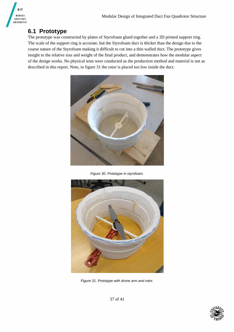
6.1 Prototype The prototype was constructed by plates of Styrofoam glued together and a 3D printed support ring.
The scale of the support ring is accurate, but the Styrofoam duct is thicker than the design due to the
coarse nature of the Styrofoam making it difficult to cut into a thin walled duct. The prototype gives
insight to the relative size and weight of the final product, and demonstrates how the modular aspect
of the design works. No physical tests were conducted as the production method and material is not as
described in this report. Note, in figure 31 the rotor is placed too low inside the duct.
Figure 30. Prototype in styrofoam.
Figure 31. Prototype with drone arm and rotor.
Modular Design of Integrated Duct Fan Quadrotor Structure
38 of 41
7 Conclusion The goal for this project has been to reduce the mass of a ducted fanned shielding design for quadrotors
without affecting the positive thrust performance from the ducts. The thesis continues the work of a
previous master thesis written by Sethuram Balakrishnan and introduces a new design for his ducted
fanned shielding design for the DJI flame wheel f450 quadrotor. A systematic design and material
selection process together with simulations has resulted in a solution that reduces the mass significantly.
A prototype for one of the rotors was constructed. During the preliminary work design requirements
were compiled. As a result of the design process the following specifications were fulfilled.
- Lower weight.
- Stiff frame. As the frame arms are from the original quadrotor the arms have the desired
stiffness.
- Modular ducts. All three main part in the design are modular.
- Inside geometry approximately the same as Balakrishnan’s design.
- Low cost.
The total mass of the final design is 650g. This reduces the mas from Balakrishnans design with
1150𝑔 − 650𝑔 = 500𝑔
For the ducted fan solution, this gives a percentage weight loss of
500𝑔
1150𝑔⋅ 100 = 43.5%
Modular Design of Integrated Duct Fan Quadrotor Structure
39 of 41
7.1 Suggestions for future work Due to a limited time frame available on this project, proper physical testing of the finished product was
not conducted. A prototype of one duct and support ring was manufactured for visual purposes, but more
testing is needed to verify if the finished product is acceptable. The duct especially could be analyzed
more extensively, with more detailed physical analysis to verify if the construction is rigid enough to
provide adequate protection of the propeller. A new flow analysis may also be needed to check if the
surface roughness of the rigid polymer foam disturbs the airflow through the duct. Testing of the actual
flight times, and comparing them to the projected flight times calculated in this rapport is also something
that could be done in future work.

Modular Design of Integrated Duct Fan Quadrotor Structure
40 of 41
8 References
[1] S. Balakrishnan, "Duct fanned shielding design for quadrotors," UiT, Narvik, 2016.
[2] N. Cross, Engineering Design Methods, strategies for Product Design, Chichester: John Wiley &
Sons Ltd, 2000.
[3] DJI, "FlameWheel 450 User Manual," DJI, 2015.
[4] J. Dickey, "quadcopterproject," 2011. [Online]. Available:
https://quadcopterproject.wordpress.com/battery-and-flight-time/. [Accessed Januar 2017].
[5] M. F. Ashby, Materials Selection in Mechanical Design, Butterworth-Heinemann, 2005.
[6] C. Udumbasseri. [Online]. Available:
https://www.slideshare.net/ChandranUdumbasseri1/manufacturing-polyurethane-foams.
[Accessed 23 Mai 2017].
[7] J. Glenn, "NASA Glenn Research Center, The Drag Equation," 05 2015. [Online]. Available:
https://www.grc.nasa.gov/www/k-12/airplane/drageq.html. [Accessed 16 05 2017].
[8] J. Glenn, "Nasa Glenn Research Center, Shape Effects on Drag," 2015. [Online]. Available:
https://www.grc.nasa.gov/www/k-12/airplane/shaped.html. [Accessed 16 05 2017].
[9] "The Engineering ToolBox," [Online]. Available: http://www.engineeringtoolbox.com/air-
density-specific-weight-d_600.html. [Accessed 18 05 2017].
[10] T. Schive, "Meccanica," [Online]. Available: http://meccanica.uit.no/fasthet/20t.html. [Accessed
24 May 2017].
[11] P. E. Thoresen, "iu.hio.no," 31 March 2004. [Online]. Available:
http://www.iu.hio.no/~pererikt/Konstr/mekanikk-en/presentasjoner/leksjon-17.ppt. [Accessed 26
May 2017].
[12] Mechanicalc, "MechaniCalc," [Online]. Available: https://mechanicalc.com/reference/beam-
analysis. [Accessed 28 May 2017].
[13] TWP, "twpinc.com," [Online]. Available: https://www.twpinc.com/wire-mesh-
material/aluminum/aluminum-bird-mesh.
[14] P. E. Thoresen, "iu.hio.no," 02 May 2006. [Online]. Available:
http://www.iu.hio.no/~pererikt/Konstr/mekanikk-en/presentasjoner/. [Accessed 25 May 2017].

Modular Design of Integrated Duct Fan Quadrotor Structure
41 of 41
Page 1
Appendix
A. 3D models from Inventor
Figure A-1. ISO view of support ring.

Page 2
Figure A-2 Top view of support ring.
Figure A-3. Front view of support ring.

Page 3
Figure A-4. Side view of support ring.
Figure A-5. ISO view of duct.
Page 4
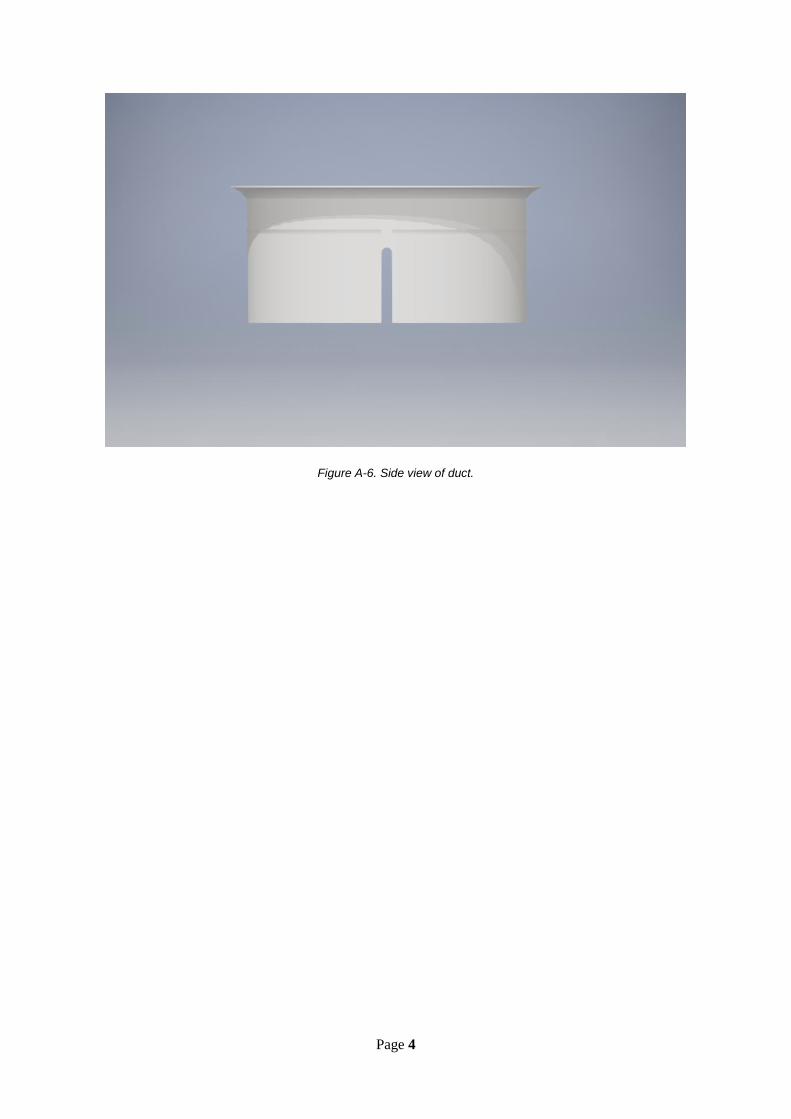
Figure A-6. Side view of duct.
Page 5
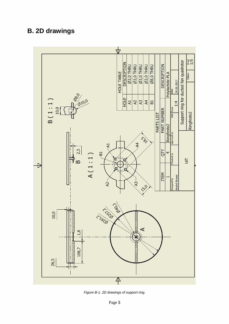
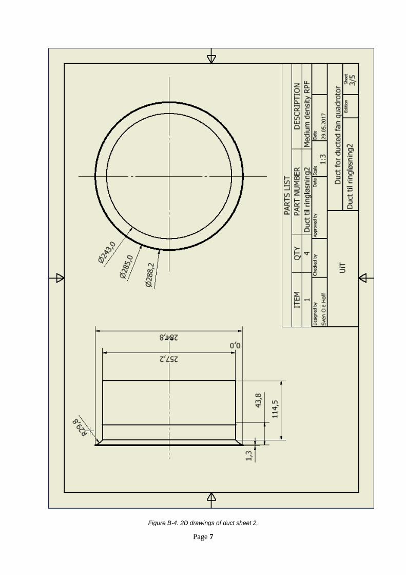
B. 2D drawings
Figure B-1. 2D drawings of support ring.
Page 6
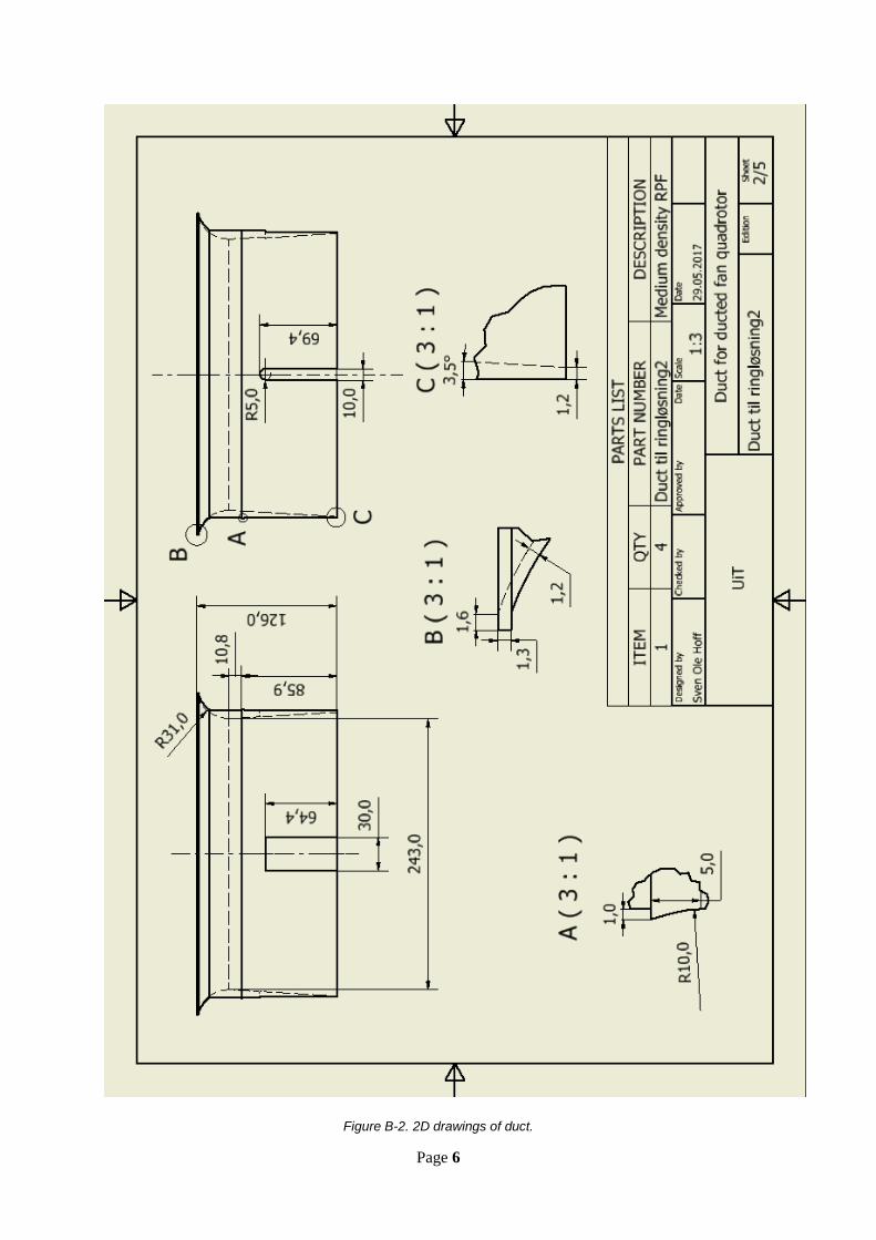
Figure B-2. 2D drawings of duct.
Page 7
Figure B-4. 2D drawings of duct sheet 2.

Page 8
Figure B-4. Wire mesh top cover.
Page 9
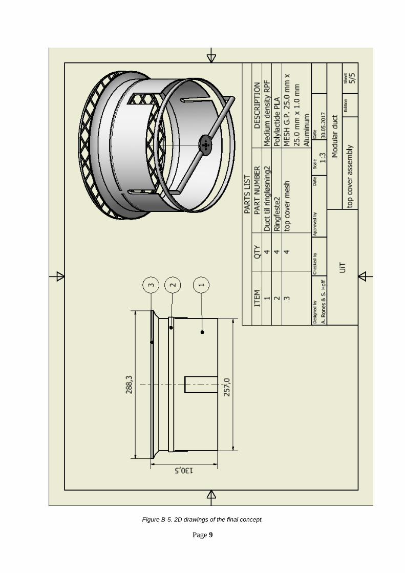
Figure B-5. 2D drawings of the final concept.

Page 10
C. Thrust values from Balakrishnan’s testing. Table C-1. Thrust at different RPM [1].
Page 11
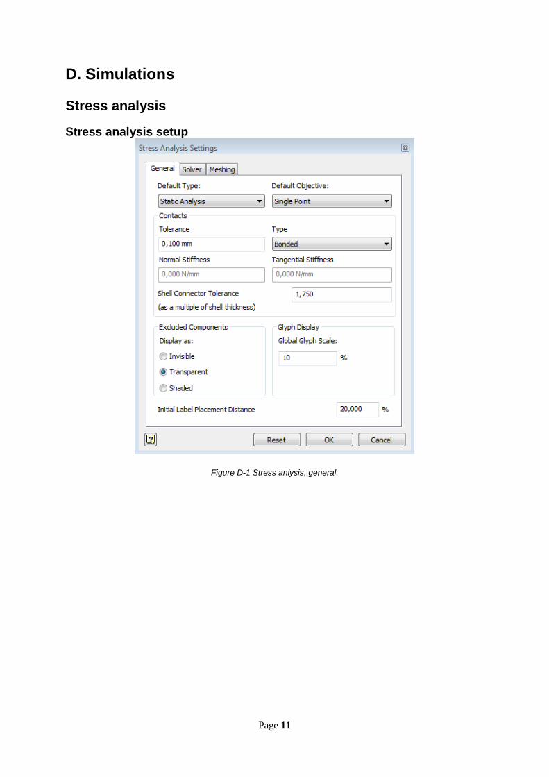
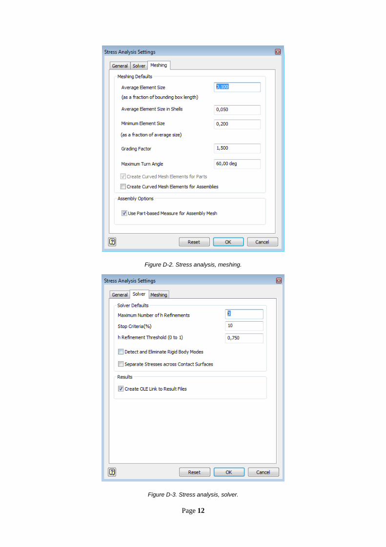
D. Simulations
Stress analysis
Stress analysis setup
Figure D-1 Stress anlysis, general.
Page 12
Figure D-2. Stress analysis, meshing.
Figure D-3. Stress analysis, solver.

Page 13
Stress analysis report ring structure
Analyzed File: Ringfeste2.ipt
Autodesk Inventor Version: 2016 (Build 200138000, 138)
Creation Date: 30.05.2017, 20:05
Simulation Author: sho114
Summary:
Project Info (iProperties)
Summary
Author André
Project
Part Number Ringfeste2
Designer André
Cost kr 0,00
Date Created 04.04.2017
Status
Design Status WorkInProgress
Physical
Material ABS Plastic
Density 1,2456 g/cm^3
Mass 0,0332218 kg
Page 14
Area 34727,1 mm^2
Volume 26671,4 mm^3
Center of Gravity
x=0,00375271 mm
y=21,0007 mm
z=0,000010765 mm
Note: Physical values could be different from Physical values used by FEA reported below.
Simulation:1
General objective and settings:
Design Objective Single Point
Simulation Type Static Analysis
Last Modification Date 30.05.2017, 19:45
Detect and Eliminate Rigid Body Modes No
Mesh settings:
Avg. Element Size (fraction of model diameter) 0,1
Min. Element Size (fraction of avg. size) 0,2
Grading Factor 1,5
Max. Turn Angle 60 deg
Create Curved Mesh Elements Yes
Material(s)
Name ABS Plastic
General
Mass Density 1,2456 g/cm^3
Yield Strength 54,9995 MPa

Page 15
Ultimate Tensile Strength 46,9947 MPa
Stress
Young's Modulus 3,30259 GPa
Poisson's Ratio 0,38 ul
Shear Modulus 1,19659 GPa
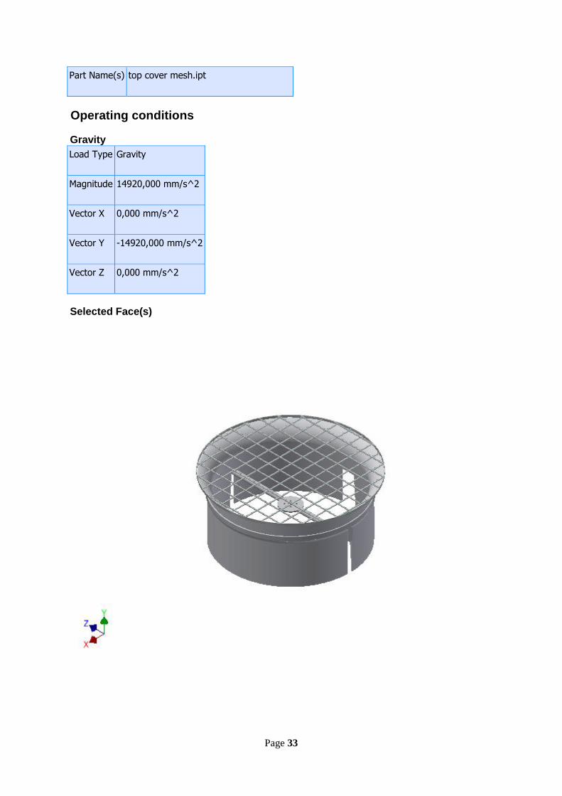
Part Name(s) Ringfeste2.ipt
Operating conditions
Gravity
Load Type Gravity
Magnitude 14920,000 mm/s^2
Vector X 0,000 mm/s^2
Vector Y -14920,000 mm/s^2
Vector Z 0,000 mm/s^2
Selected Face(s)

Page 16
Force:1
Load Type Force
Magnitude 1,067 N
Vector X 0,000 N
Vector Y -1,067 N
Vector Z 0,000 N
Selected Face(s)
Fixed Constraint:1
Constraint Type Fixed Constraint
Selected Face(s)

Page 17
Results
Reaction Force and Moment on Constraints
Constraint Name
Reaction Force Reaction Moment
Magnitude Component (X,Y,Z) Magnitude Component (X,Y,Z)
Fixed Constraint:1 1,56954 N
0 N
0,00134275 N m
0 N m
1,56954 N 0 N m
0 N 0,00134275 N m
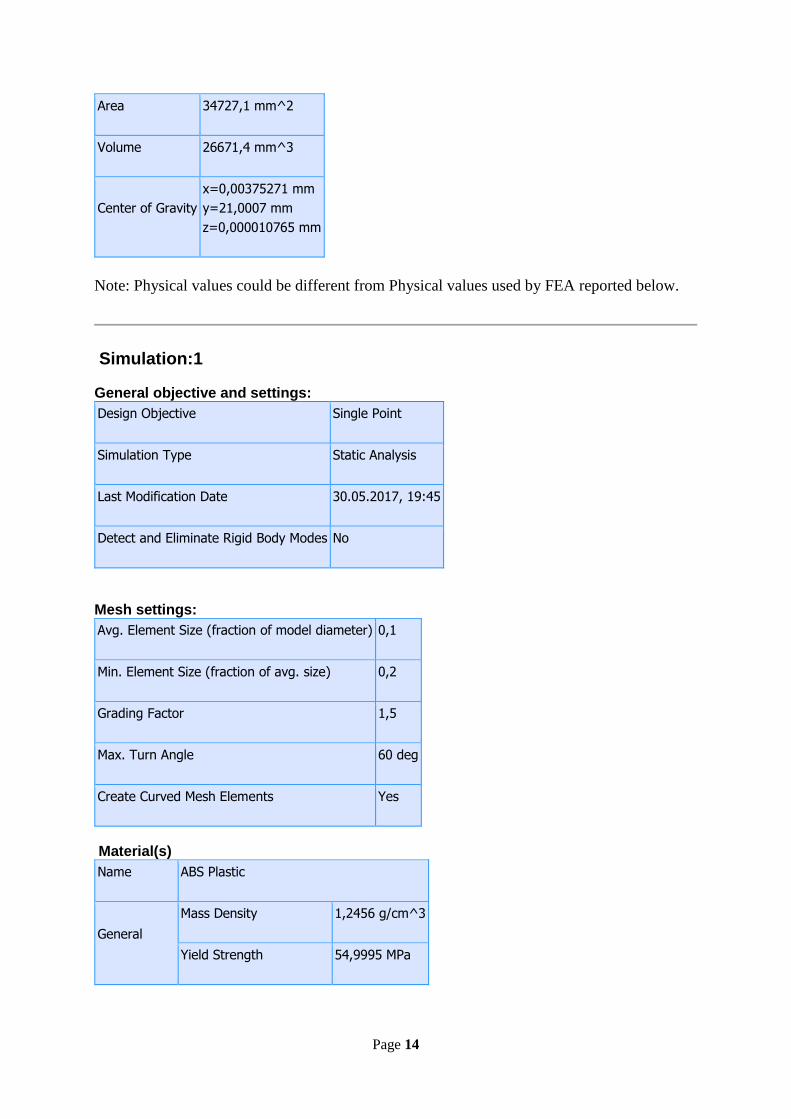
Result Summary
Name Minimum Maximum
Volume 26672,6 mm^3
Mass 0,0332233 kg
Von Mises Stress 0,000227086 MPa 10,5575 MPa
1st Principal Stress -5,63905 MPa 8,57468 MPa
3rd Principal Stress -12,964 MPa 1,3255 MPa
Page 18
Displacement 0 mm 2,37515 mm
Safety Factor 5,2095 ul 15 ul
Figures
Von Mises Stress

Page 19
1st Principal Stress
3rd Principal Stress

Page 20
Displacement
Safety Factor

Page 21
Stress analysis report Duct
Analyzed File: Duct til ringløsning2.ipt
Autodesk Inventor Version: 2016 (Build 200138000, 138)
Creation Date: 31.05.2017, 14:33
Simulation Author: sho114
Summary:
Project Info (iProperties)
Summary
Title Arm integrert.STEP
Project
Part Number Duct til ringløsning2
Description STEP AP214
Revision Number ANY
Designer sho114
Cost kr 0,00
Date Created 28.02.2017
Status
Design Status WorkInProgress
Physical
Material Polystyrene
Page 22
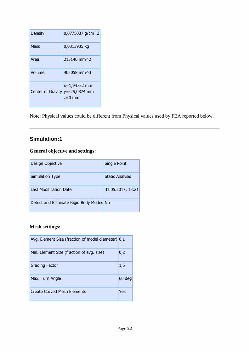
Density 0,0775037 g/cm^3
Mass 0,0313935 kg
Area 215140 mm^2
Volume 405058 mm^3
Center of Gravity
x=1,94752 mm
y=-25,0874 mm
z=0 mm
Note: Physical values could be different from Physical values used by FEA reported below.
Simulation:1
General objective and settings:
Design Objective Single Point
Simulation Type Static Analysis
Last Modification Date 31.05.2017, 13:21
Detect and Eliminate Rigid Body Modes No
Mesh settings:
Avg. Element Size (fraction of model diameter) 0,1
Min. Element Size (fraction of avg. size) 0,2
Grading Factor 1,5
Max. Turn Angle 60 deg
Create Curved Mesh Elements Yes

Page 23
Material(s)
Name Polystyrene
General
Mass Density 0,0775037 g/cm^3
Yield Strength 3,49978 MPa
Ultimate Tensile Strength 5,10212 MPa
Stress
Young's Modulus 0,199996 GPa
Poisson's Ratio 0,33 ul
Shear Modulus 0,0751866 GPa
Part Name(s) Duct til ringløsning2.ipt
Operating conditions
Gravity
Load Type Gravity
Magnitude 14920,000 mm/s^2
Vector X 0,000 mm/s^2
Vector Y -14920,000 mm/s^2
Vector Z 0,000 mm/s^2
Page 24
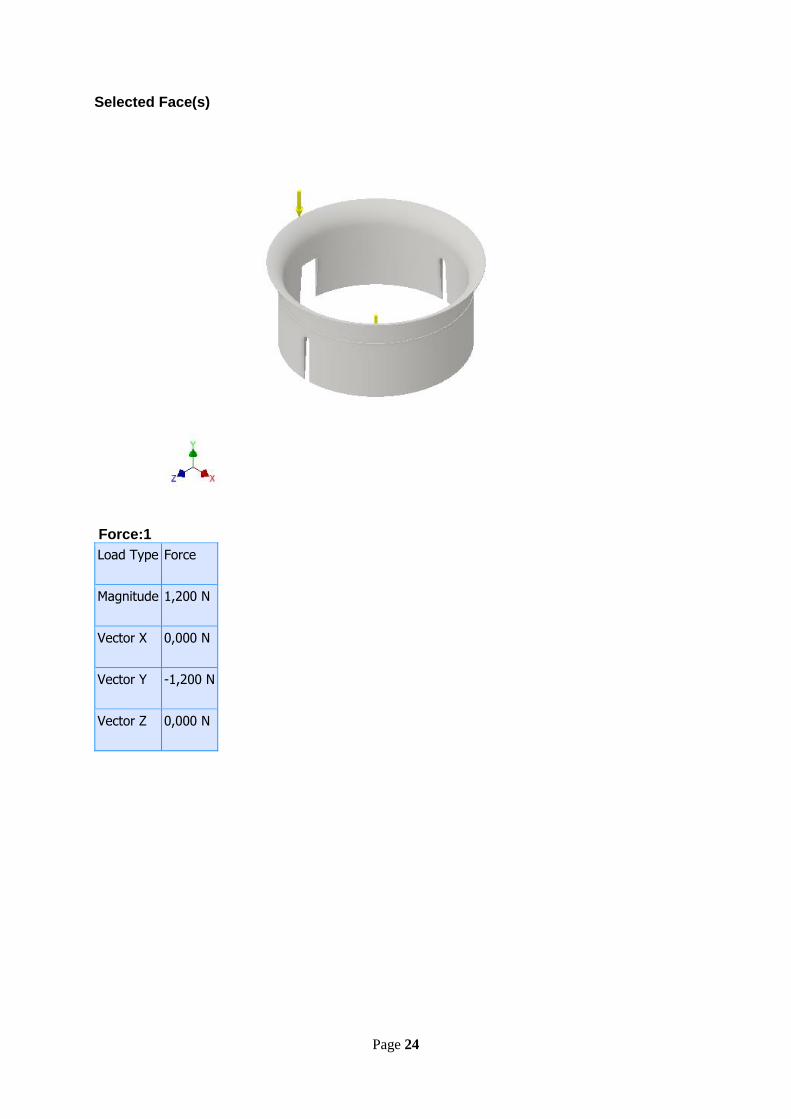
Selected Face(s)
Force:1
Load Type Force
Magnitude 1,200 N
Vector X 0,000 N
Vector Y -1,200 N
Vector Z 0,000 N

Page 25
Selected Face(s)
Fixed Constraint:1
Constraint Type Fixed Constraint
Selected Face(s)
Fixed Constraint:2
Constraint Type Fixed Constraint
Page 26
Selected Face(s)
Results
Reaction Force and Moment on Constraints
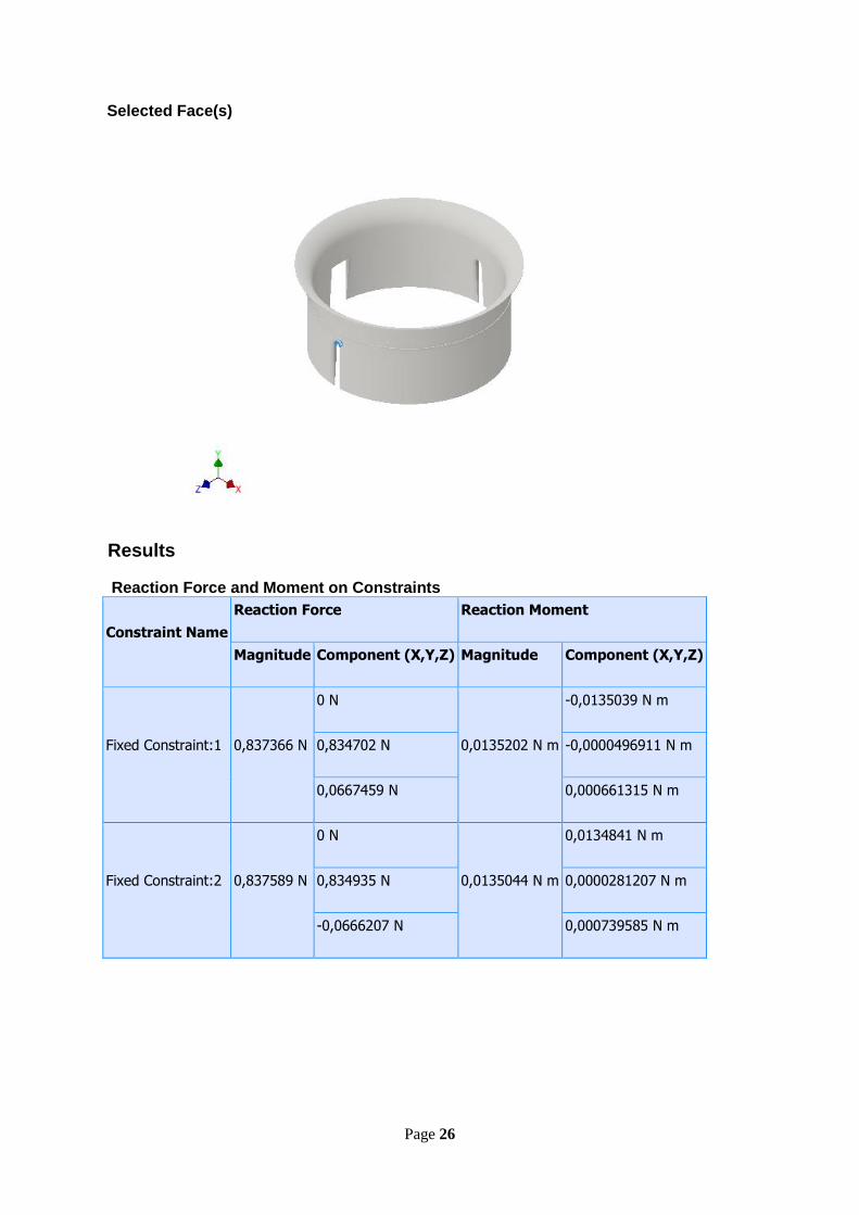
Constraint Name
Reaction Force Reaction Moment
Magnitude Component (X,Y,Z) Magnitude Component (X,Y,Z)
Fixed Constraint:1 0,837366 N
0 N
0,0135202 N m
-0,0135039 N m
0,834702 N -0,0000496911 N m
0,0667459 N 0,000661315 N m
Fixed Constraint:2 0,837589 N
0 N
0,0135044 N m
0,0134841 N m
0,834935 N 0,0000281207 N m
-0,0666207 N 0,000739585 N m
Page 27
Result Summary
Name Minimum Maximum
Volume 405058 mm^3
Mass 0,0313935 kg
Von Mises Stress 0,0000579012 MPa 0,135268 MPa
1st Principal Stress -0,091042 MPa 0,176114 MPa
3rd Principal Stress -0,23364 MPa 0,067006 MPa
Displacement 0 mm 0,146755 mm
Safety Factor 15 ul 15 ul
Figures
Von Mises Stress

Page 28
1st Principal Stress
3rd Principal Stress

Page 30
Stress analysis report of whole structure
Analyzed File: top cover assembly.iam
Autodesk Inventor Version: 2016 (Build 200138000, 138)
Creation Date: 31.05.2017, 14:49
Simulation Author: sho114
Summary:
Project Info (iProperties)
Summary
Author aro083
Project
Part Number top cover assembly
Designer aro083
Cost kr 0,00
Date Created 29.05.2017
Status
Design Status WorkInProgress
Physical
Mass 0,145438 kg
Area 300177 mm^2
Volume 461664 mm^3
Page 31
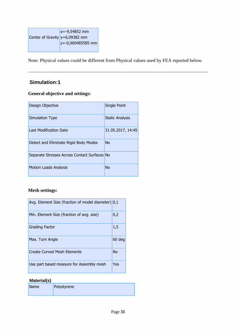
Center of Gravity
x=-9,54852 mm
y=6,09382 mm
z=-0,000485585 mm
Note: Physical values could be different from Physical values used by FEA reported below.
Simulation:1
General objective and settings:
Design Objective Single Point
Simulation Type Static Analysis
Last Modification Date 31.05.2017, 14:45
Detect and Eliminate Rigid Body Modes No
Separate Stresses Across Contact Surfaces No
Motion Loads Analysis No
Mesh settings:
Avg. Element Size (fraction of model diameter) 0,1
Min. Element Size (fraction of avg. size) 0,2
Grading Factor 1,5
Max. Turn Angle 60 deg
Create Curved Mesh Elements No
Use part based measure for Assembly mesh Yes
Material(s)
Name Polystyrene

Page 32
General
Mass Density 0,0775037 g/cm^3
Yield Strength 3,49978 MPa
Ultimate Tensile Strength 5,10212 MPa
Stress
Young's Modulus 0,199996 GPa
Poisson's Ratio 0,33 ul
Shear Modulus 0,0751866 GPa
Part Name(s) Duct til ringløsning2.ipt
Name ABS Plastic
General
Mass Density 1,2456 g/cm^3
Yield Strength 54,9995 MPa
Ultimate Tensile Strength 46,9947 MPa
Stress
Young's Modulus 3,30259 GPa
Poisson's Ratio 0,38 ul
Shear Modulus 1,19659 GPa
Part Name(s) Ringfeste2.ipt
Name Aluminum 6061
General
Mass Density 2,7 g/cm^3
Yield Strength 275 MPa
Ultimate Tensile Strength 310 MPa
Stress
Young's Modulus 68,9 GPa
Poisson's Ratio 0,33 ul
Shear Modulus 25,9023 GPa
Page 33
Part Name(s) top cover mesh.ipt
Operating conditions
Gravity
Load Type Gravity
Magnitude 14920,000 mm/s^2
Vector X 0,000 mm/s^2
Vector Y -14920,000 mm/s^2
Vector Z 0,000 mm/s^2
Selected Face(s)

Page 34
Fixed Constraint:1
Constraint Type Fixed Constraint
Selected Face(s)
Contacts (Bonded)
Name Part Name(s)
Bonded:1 Duct til ringløsning2:1
Ringfeste2:1
Bonded:2 Duct til ringløsning2:1
Ringfeste2:1
Bonded:3 Duct til ringløsning2:1
Ringfeste2:1
Bonded:4 Duct til ringløsning2:1
Ringfeste2:1

Page 35
Bonded:5 Duct til ringløsning2:1
Ringfeste2:1
Bonded:6 Duct til ringløsning2:1
top cover mesh:1
Bonded:7 Duct til ringløsning2:1
top cover mesh:1
Bonded:8 Duct til ringløsning2:1
top cover mesh:1
Bonded:9 Duct til ringløsning2:1
top cover mesh:1
Bonded:10 Duct til ringløsning2:1
top cover mesh:1
Bonded:11 Duct til ringløsning2:1
top cover mesh:1
Bonded:12 Duct til ringløsning2:1
top cover mesh:1
Bonded:13 Duct til ringløsning2:1
top cover mesh:1
Bonded:14 Duct til ringløsning2:1
top cover mesh:1
Bonded:15 Duct til ringløsning2:1
top cover mesh:1
Bonded:16 Duct til ringløsning2:1
top cover mesh:1
Bonded:17 Duct til ringløsning2:1
top cover mesh:1
Bonded:18 Duct til ringløsning2:1
top cover mesh:1
Bonded:19 Duct til ringløsning2:1
Ringfeste2:1

Page 36
Bonded:20 Duct til ringløsning2:1
Ringfeste2:1
Results
Reaction Force and Moment on Constraints
Constraint Name
Reaction Force Reaction Moment
Magnitude Component (X,Y,Z) Magnitude Component (X,Y,Z)
Fixed Constraint:1 2,04495 N
0 N
0,00115446 N m
-0,00115446 N m
2,04495 N 0 N m
0 N 0 N m
Result Summary
Name Minimum Maximum
Volume 461664 mm^3
Mass 0,145438 kg
Von Mises Stress 0,0000441835 MPa 9,25216 MPa
1st Principal Stress -2,39125 MPa 10,3239 MPa
3rd Principal Stress -11,165 MPa 1,99646 MPa
Displacement 0 mm 0,387195 mm
Safety Factor 7,22668 ul 15 ul
Contact Pressure 0 MPa 16,9355 MPa
Contact Pressure X -2,12996 MPa 1,34424 MPa
Contact Pressure Y -2,22791 MPa 4,25884 MPa
Contact Pressure Z -16,6096 MPa 14,293 MPa

Page 37
Figures
Von Mises Stress
1st Principal Stress

Page 38
3rd Principal Stress
Displacement

Page 39
Safety Factor
Contact Pressure
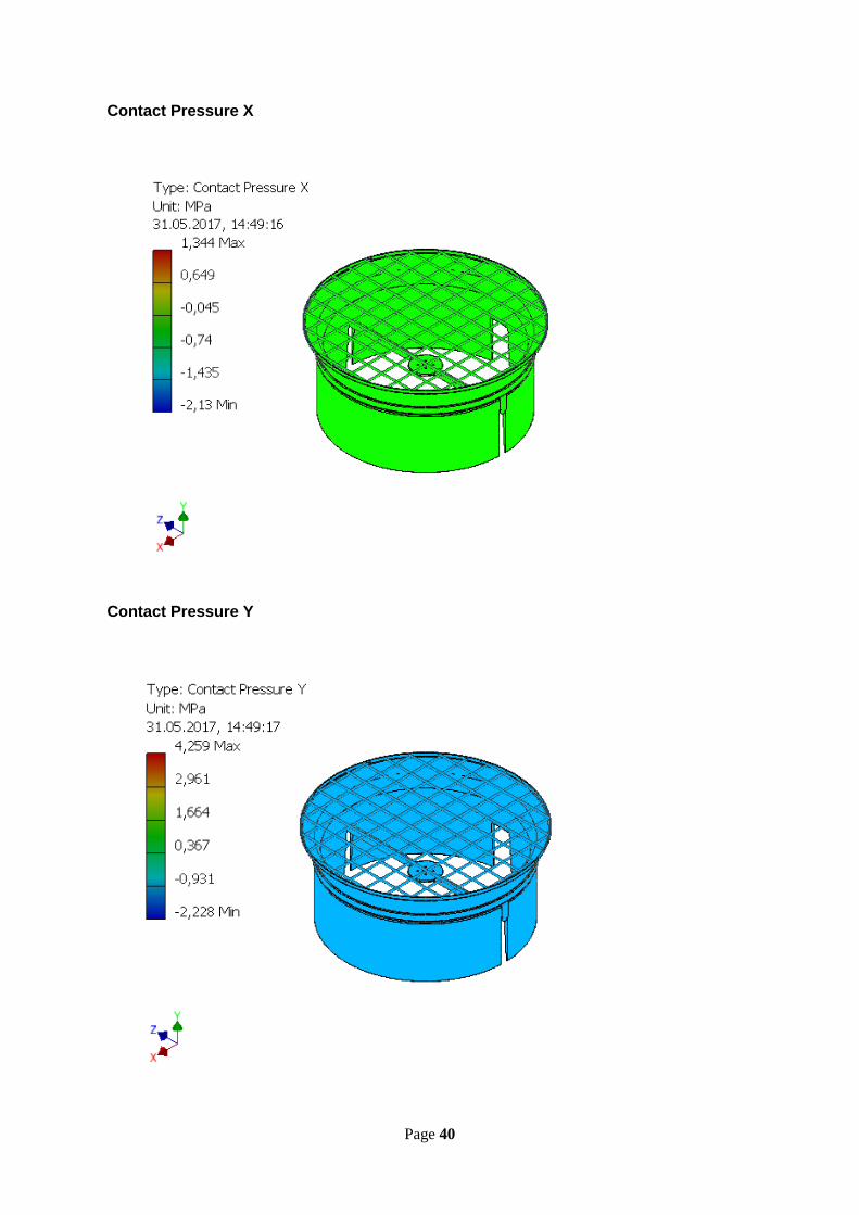
Page 40
Contact Pressure X
Contact Pressure Y
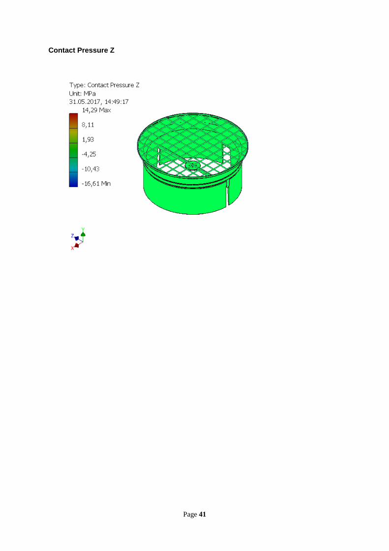

Page 42
E. Prototype Pictures from prototype production

Page 43

Page 44